Bottom Outlets
36
CE 458 Design of Hydraulic Structures 3.1 3. BOTTOM OUTLETS
-
Upload
nikom-kraitud -
Category
Documents
-
view
56 -
download
6
description
Bottom Outlets
Transcript of Bottom Outlets

CE 458 Design of Hydraulic Structures
3.1
3. BOTTOM OUTLETS
CE 458 Design of Hydraulic Structures
3.2
Purpose of bottom outlet Bottom outlet is the outlet structure with the lowest elevation which can serve for
various purposes:
Filling of the reservoir
Drawdown of the reservoir
Flushing of sediments
Discharging surplus water
A bottom outlet must be provided in every dam as a safety structure to control reservoir
level and for emergency operations.

CE 458 Design of Hydraulic Structures
3.3
The load test of a dam is performed during the first filling of the reservoir.
The filling must be made progressively by accounting for the stability and the
watertightness of both the dam and its surroundings at certain levels of the
reservoir.
The load test procedure during the first filling is only amenable if a bottom outlet is
available.
The bottom outlet must thus be designed that the reservoir level can be kept
constantly under arbitrary levels

CE 458 Design of Hydraulic Structures
3.4
Drawdown of reservoir
Qo is the reservoir approach flow corresponding to an average value over a certain
time period such as several weeks or even months.
The choice of Qo depends on inflow hydrograph and reservoir storage
characteristics.
Qo
Qb
Fp h
zo

CE 458 Design of Hydraulic Structures
3.5
Qb > Qo
Qb is the design discharge of the bottom outlet.
The hydrostatic pressure force on the dam face is
2/BhF 2p
A drawdown of the reservoir level is followed by a stress relief. Accordingly,
drawing down an endangered dam is highly efficient.
Drawdown by the bottom outlet has to be fast

CE 458 Design of Hydraulic Structures
3.6
Design guidelines for emergency drawdown:
Rapid drawdown of a reservoir within the shortest time lapse, the maximum Qb.
The tailwater valley should not be damaged by Qb.
Qb < QL
where QL is the limit tailwater discharge.
The drawdown should not cause shore slides.
Qb < (Qo + Qs)
where Qs is the allowable discharge for shore protection.

CE 458 Design of Hydraulic Structures
3.7
The allowable discharge Qs can be estimated from the limit drawdown velocity us
t
hus
and
Qs = us A where A is the reservoir surface area. The limit drawdown velocity is related to allowable pore water velocity of the
groundwater flow along the shores of the reservoir.

CE 458 Design of Hydraulic Structures
3.8
Optimization of head-discharge relation for design discharge of bottom outlet.
h
Qb
Qo QL
Qo+Qs
h=h(Qb))
Solution domain
Acceptable bottom outlet dimensions

CE 458 Design of Hydraulic Structures
3.9
For flood conditions, the approach discharge Qo is large and the limit discharge QL
is small. Then, domain of solution shrinks, and can even vanish.
During flood periods, a drawdown is thus impossible.
Usually, one would choose average discharge conditions for the design.
The drawdown time is an important parameter. Under emergency, one would like
to draw down the top layers of the reservoir only, in a few days or weeks.
Bottom outlet is not a structure for permanent use due to limitations regarding
cavitation, hydrodynamic forces, abrasion and vibrations. It should, however, allow
a complete emptying of the reservoir when necessary.
CE 458 Design of Hydraulic Structures
3.10
Flushing of sediments
In certain cases, bottom outlets are used for sediment flushing.
Continuity of the sediment transport is important. If it deposits in the tailwater the
bottom outlet may be submerged and thus endangered.
The ratio between water and sediment has to be such that it corresponds to the
transport capacity of the tailwater.

CE 458 Design of Hydraulic Structures
3.11
Flood and residual discharge
Combined use of overflow spillway and the bottom outlet may be allowed for flood
conditions.
For this purpose multiple bottom outlets may be constructed.
A bottom outlet designed according to previous criteria is normally too large to fit
for the control of residual discharge.
It had to be operated permanently with an extremely small opening not suited
hydraulically. Therefore, a small outlet is often added to satisfy the needs for
residual discharge.

CE 458 Design of Hydraulic Structures
3.12
Design Principles
A useful design is the combination of diversion tunnel and bottom outlet.
Karakaya dam: 1 Intake structure, 2 Diversion tunnels, 3 Bottom outlet chambers, 4 Upstream cofferdam, 5 Service building, 6 Outlet works, 7 Powerhouse.

CE 458 Design of Hydraulic Structures
3.13
For smaller dams, a culvert type bottom outlet may also be considered because of the
simple design.
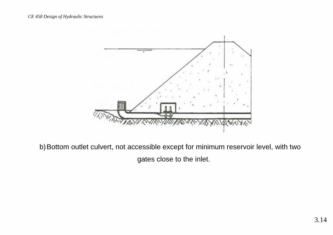
Possible arrangements for the bottom outlet
a) Diversion tunnel used as bottom outlet, with access through a shaft.
CE 458 Design of Hydraulic Structures
3.14
b) Bottom outlet culvert, not accessible except for minimum reservoir level, with two
gates close to the inlet.

CE 458 Design of Hydraulic Structures
3.15
c) Diversion tunnel used as combined spillway and bottom outlet for morning glory spillways.

CE 458 Design of Hydraulic Structures
3.16
d) Gravity dam with bottom outlet that is much shorter than for an earth dam.

CE 458 Design of Hydraulic Structures
3.17
Technical requirements for a bottom outlet
Smooth flow for completely opened structure.
Excellent performance for all flows under partial openings.
Effective energy dissipation at terminal outlets.
Structure without leakage.
Simple and immediate application.
Easy access for maintenance and service.
Economic and useful design.
Long life.

CE 458 Design of Hydraulic Structures
3.18
Hydraulic requirements for a bottom outlet
Pressurized flow upstream of the gate.
Free surface flow downstream of the gate.
A trash rack is provided at the inlet.

CE 458 Design of Hydraulic Structures
3.19
The tunnel often has a horseshoe profile.
The tunnel section contracts to a rectangular cross-section shortly before the gate
chamber.
Downstream from the gate chamber, the tunnel is expanded both laterally and at
the tunnel ceiling.
For long tunnels an aeration conduit behind the gate chamber may be required.
The air supply conduit has to be designed so that the gate chamber is safe against
submergence from the tunnel.
It is imperative that submergence of the bottom outlet is inhibited. The discharge is
then fully controlled with the gates.
Submergence will cause the mechanical equipment be wetted in the gate section.

CE 458 Design of Hydraulic Structures
3.20
Hydraulic phenomena that must be considered in the design of bottom outlet
Average velocity at the bottom outlet is large.
Cavitation
Abrasion
Aerated flow
Sediment flow due to reservoir sedimentation
Floating debris or sediment deposition
Gate vibration

CE 458 Design of Hydraulic Structures
3.21
Air entrainment
Free gate outflow reduces the potential of gate vibration and cavitation.
A bottom outlet should always be designed for free surface flow.
Aeration of flow just after the gate is required for rapid energy dissipation and to
reduce the risk of cavitation.
The aeration of flow may originate from three different sources

CE 458 Design of Hydraulic Structures
3.22
1) Tunnel outlet in a counter-current air flow along the outlet roof.
2) Air supply conduit by which the underpressure of the surface air is reduced.
3) Bottom aerator that counter problems with cavitation damage.

CE 458 Design of Hydraulic Structures
3.23
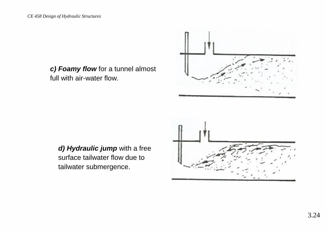
Flow types (without bottom aerator)
a) Spray flow for relative gate
opening below 10%, with an
extremely high air entrainment.
b) Free flow as typical for bottom
outlets, and accompanied by features
of supercritical flow, such as shock
waves and two-phase flow.
.
CE 458 Design of Hydraulic Structures
3.24
c) Foamy flow for a tunnel almost
full with air-water flow.
d) Hydraulic jump with a free
surface tailwater flow due to
tailwater submergence.

CE 458 Design of Hydraulic Structures
3.25
In applications, cases e and f should be avoided because of possibility of
dangerous surging in the channel.
e) Hydraulic jump with transition to
pressurized tailwater flow.
f) Fully pressurized flow caused by a
deep tailwater submergence.

CE 458 Design of Hydraulic Structures
3.26
Gate Controlled Discharge
Gate flow may be either free or submerged. For free gate flow, the space behind the
gate is filled with air of pressure head ha. If the efflux is into the atmosphere, ha=0.
a0
a Cca
Qa
Q

CE 458 Design of Hydraulic Structures
3.27
Based on energy considerations, the underflow discharge of a gate is given by
2/1acec )haChH(g2abCQ
where Cc is the contraction coefficient,
a the gate opeing,
b the gate width, and
H-Δhe the head on the gate with Δhe the head loss from the entrance to the
gate section.
The contraction coefficient is dependent on the gate geometry and opening. For quick calculations of flow rate as function of gate opening one can assume:
40c )a/a(2.08.0C

CE 458 Design of Hydraulic Structures
3.28
Cavitation Cavitation is defined as formation of bubble or void in a liquid.
Cavitation occurs by decreasing the local pressure under constant temperature.
The local pressure reduction in a fluid flow can be caused by:
a decrease of total energy head because of increase in elevation,
a local increase of velocity and
turbulence, vortices or large scale separation.

CE 458 Design of Hydraulic Structures
3.29
The water flowing in hydraulic structures contains air bubbles of various sizes and with
numerous impurities. These conditions are necessary to initiate cavitation.
The hydrodynamic parameter describing the cavitation process is cavitation index
where
p is local pressure,
pv is vapor pressure and
V0 is the reference velocity typically of the upstream flow.
g2/V
hh
2/V
pp20
v20
v

CE 458 Design of Hydraulic Structures
3.30
Temperature (oC)
p v(k
Pa)
0 10 20 30 40 50 600
5
10
15
20
Vapor pressure for water

CE 458 Design of Hydraulic Structures
3.31
Example: a sudden into-the-flow offset
> 1.8 : no cavitation
0.3 < < 1.8 : Developed cavitation < 0.3 : Supercavitation
= 1.8 : Incipient cavitation where cavitation bubbles occasionally can be observed.
CE 458 Design of Hydraulic Structures
3.32
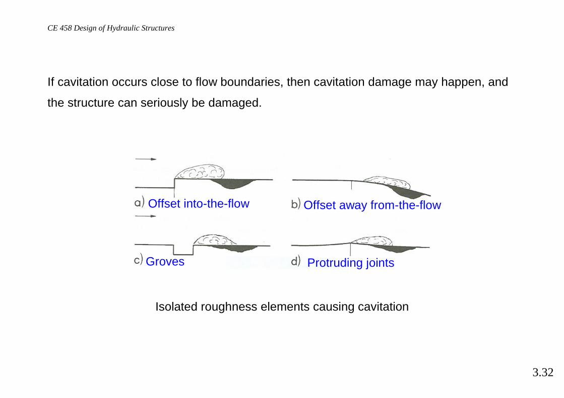
If cavitation occurs close to flow boundaries, then cavitation damage may happen, and
the structure can seriously be damaged.
Isolated roughness elements causing cavitation
Offset into-the-flow Offset away from-the-flow
Groves Protruding joints

CE 458 Design of Hydraulic Structures
3.33
Incipient cavitation for into-the-flow offset.

CE 458 Design of Hydraulic Structures
3.34
Incipient cavitation index for chamfered offset.

CE 458 Design of Hydraulic Structures
3.35
Control of cavitation Cavitation damage can be controlled by two methods:
Control of cavitation index by geometry
Control of cavitation damage by aeration

CE 458 Design of Hydraulic Structures
3.36
Steps in cavitation control
Prediction of water surface profiles.
Determination of pressure head curves.
Computation of cavitation index curves.
If there are locations where cavitation is predicted, then the geometry of the
structure or smoothness of the boundary has to be improved.
If both approaches fail, the flow has to be aerated.
Capacity of a structure with an aerated flow has to be larger because of the
increase of air-water discharge.