Bosch Global - BODAS RE 95220/03.09 1 Replaces: …...RE 95220/03.09 RCE Bosch Rexroth AG...
12
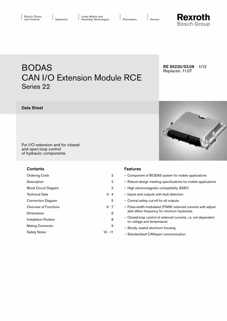
Linear Motion and Assembly Technologies Service Pneumatics Hydraulics Electric Drives and Controls BODAS CAN I/O Extension Module RCE Series 22 Data Sheet For I/O extension and for closed- and open-loop control of hydraulic components Features – Component of BODAS system for mobile applications – Robust design meeting specifications for mobile applications – High electromagnetic compatibility (EMC) – Inputs and outputs with fault detection – Central safety cut-off for all outputs – Pulse-width-modulated (PWM) solenoid currents with adjust- able dither frequency for minimum hysteresis – Closed-loop control of solenoid currents, i.e. not dependent on voltage and temperature – Sturdy, sealed aluminum housing – Standardized CANopen communication Contents Ordering Code 2 Description 2 Block Circuit Diagram 2 Technical Data 3 - 4 Connection Diagram 5 Overview of Functions 6 - 7 Dimensions 8 Installation Position 8 Mating Connector 9 Safety Notes 10 - 11 RE 95220/03.09 1/12 Replaces: 11.07
Transcript of Bosch Global - BODAS RE 95220/03.09 1 Replaces: …...RE 95220/03.09 RCE Bosch Rexroth AG...
Linear Motion andAssembly Technologies ServicePneumaticsHydraulics
Electric Drives and Controls
BODASCAN I/O Extension Module RCESeries 22
Data Sheet
For I/O extension and for closed- and open-loop control of hydraulic components
Features– Component of BODAS system for mobile applications
– Robust design meeting specifications for mobile applications
– High electromagnetic compatibility (EMC)
– Inputs and outputs with fault detection
– Central safety cut-off for all outputs
– Pulse-width-modulated (PWM) solenoid currents with adjust-able dither frequency for minimum hysteresis
– Closed-loop control of solenoid currents, i.e. not dependent on voltage and temperature
– Sturdy, sealed aluminum housing
– Standardized CANopen communication
ContentsOrdering Code 2
Description 2
Block Circuit Diagram 2
Technical Data 3 - 4
Connection Diagram 5
Overview of Functions 6 - 7
Dimensions 8
Installation Position 8
Mating Connector 9
Safety Notes 10 - 11
RE 95220/03.09 1/12Replaces: 11.07
2/12 Bosch Rexroth AG RCE RE 95220/03.09
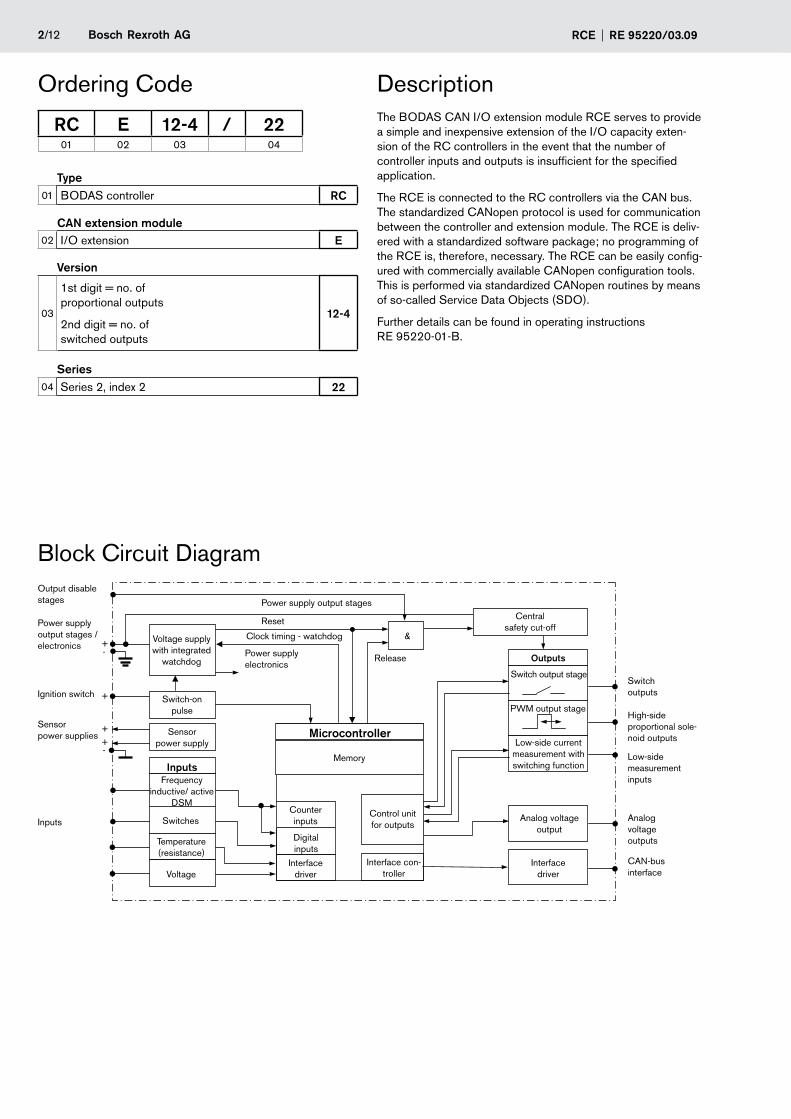
Type01 BODAS controller RC
CAN extension module02 I/O extension E
Version
03
1st digit = no. of proportional outputs
2nd digit = no. of switched outputs
12-4
Series04 Series 2, index 2 22
RC E 12-4 / 2201 02 03 04
Ordering Code
Block Circuit Diagram
DescriptionThe BODAS CAN I/O extension module RCE serves to provide a simple and inexpensive extension of the I/O capacity exten-sion of the RC controllers in the event that the number of controller inputs and outputs is insufficient for the specified application.
The RCE is connected to the RC controllers via the CAN bus. The standardized CANopen protocol is used for communication between the controller and extension module. The RCE is deliv-ered with a standardized software package; no programming of the RCE is, therefore, necessary. The RCE can be easily config-ured with commercially available CANopen configuration tools. This is performed via standardized CANopen routines by means of so-called Service Data Objects (SDO).
Further details can be found in operating instructions RE 95220-01-B.
Output disable stages
Power supply output stages / electronics
Sensor power supplies
Inputs
Voltage supply with integrated
watchdog
Switch-on pulse
Sensor power supply
InputsFrequency
inductive/ active DSM
Switches
Temperature (resistance)
Power supply electronics
Voltage
Power supply output stages
Reset
Clock timing - watchdog
Microcontroller
Memory
Counter inputs
Digital inputs
Interface driver
Control unit for outputs
Interface con-troller
&
Release Outputs
Switch output stage
PWM output stage
Low-side current measurement with switching function
Analog voltage output
Interface driver
Switch outputs
High-side proportional sole-noid outputs
Low-side measurement inputs
Analog voltage outputs
CAN-bus interface
Central safety cut-off
Ignition switch
Bosch Rexroth AGRE 95220/03.09 RCE 3/12
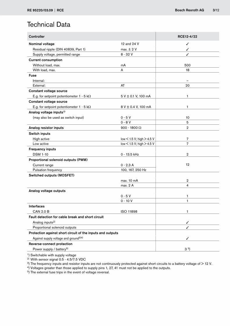
Technical Data
Controller RCE12-4/22
Nominal voltage 12 and 24 V
Residual ripple (DIN 40839, Part 1) max. ± 2 V
Supply voltage, permitted range 8 - 32 V
Current consumptionWithout load, max. mA 500With load, max. A 18
FuseInternal: –External: AT 20
Constant voltage sourceE.g. for setpoint potentiometer 1 - 5 kΩ 5 V ± 0.1 V, 100 mA 1
Constant voltage sourceE.g. for setpoint potentiometer 1 - 5 kΩ 8 V ± 0.4 V, 100 mA 1
Analog voltage inputs1)
(may also be used as switch input) 0 - 5 V 100 - 8 V 5
Analog resistor inputs 900 - 1800 Ω 2
Switch inputsHigh active low < 1.5 V; high > 4.5 V 7Low active low < 1.5 V; high > 4.5 V 7
Frequency inputs
DSM 1-10 0 - 13.5 kHz 2
Proportional solenoid outputs (PWM)12Current range 0 - 2.3 A
Pulsation frequency 100, 167, 250 Hz
Switched outputs (MOSFET)max. 10 mA 2max. 2 A 4
Analog voltage outputs0 - 5 V 10 - 10 V 1
InterfacesCAN 2.0 B ISO 11898 1
Fault detection for cable break and short circuit
Analog inputs2)
Proportional solenoid outputs
Protection against short circuit of the inputs and outputs
Against supply voltage and ground3)4)
Reverse-connect protectionPower supply / battery5) 3 3)
1) Switchable with supply voltage
2) With sensor signal 0.5 - 4.5/7.5 VDC 3) The frequency inputs and resistor inputs are not continuously protected against short circuits to a battery voltage of > 12 V. 4) Voltages greater than those applied to supply pins 1, 27, 41 must not be applied to the outputs. 5) The external fuse trips in the event of voltage reversal.

4/12 Bosch Rexroth AG RCE RE 95220/03.09
Controller RCE12-4/22
Electromagnetic compatibility
Spurious interference (motor vehicles directive 95/54/EG)
100 VRMS/m; (details on request)
Line-bound interference (ISO 7637-1/-2/-3)
Values on request
Load dump 70 V
Max. dissipation power W at 32 V 8.0
Operating temperature, case -40 to +85°C (-40 to 185°F)
Storage temperature, case -40 to +85°C (-40 to 185°F)
Vibration resistance:
Sinusoidal vibration (IEC 60068-2-6)
Values on request
Random-shaped vibration (IEC 60068-2-64, ISO 16750-3)
Values on request
Shock resistance:
Transport shock (IEC 60068-2-27)
15 g; 11 ms per spatial axis x, y, z and 6 x in each direction (pos./neg. )
Continuous shock (IEC 60068-2-29)
25 g; 6 ms per spatial axis x, y, z and 1000x in each direction (pos./neg.)
Resistance to moisture 95% (+25 to +55°C)
(IEC 60068-2-30Db; Variant 2)
Resistance to salt spray
(IEC 60068-2-11) 72 h, 35°C, 5% NaCl
Type of protection (DIN / EN 60529)1) Without / with mounted mating connector
IP54k / IP65
Case material Diecast aluminum
Weight Approx. kg 0.7
Outer dimensions Length (in mm) 187
Width (in mm) 202
Height (in mm) 45
Mating Connector 52-pin 1
28-pin 1
1) Taking installation notes into account
Technical Data
Bosch Rexroth AGRE 95220/03.09 RCE 5/12
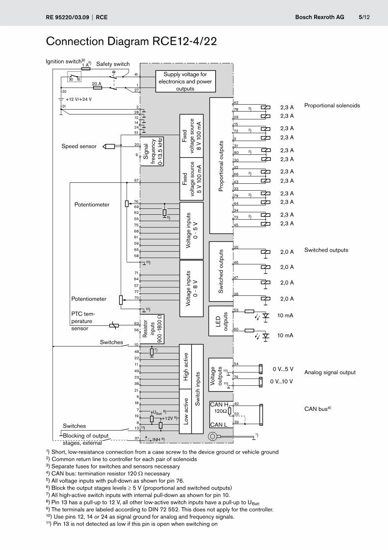
Connection Diagram RCE12-4/22
1) Short, low-resistance connection from a case screw to the device ground or vehicle ground 2) Common return line to controller for each pair of solenoids 3) Separate fuses for switches and sensors necessary 4) CAN bus: termination resistor 120 Ω necessary 5) All voltage inputs with pull-down as shown for pin 76. 6) Block the output stages levels ≥ 5 V (proportional and switched outputs) 7) All high-active switch inputs with internal pull-down as shown for pin 10. 8) Pin 13 has a pull-up to 12 V, all other low-active switch inputs have a pull-up to UBatt 9) The terminals are labeled according to DIN 72 552. This does not apply for the controller. 10) Use pins 12, 14 or 24 as signal ground for analog and frequency signals. 11) Pin 13 is not detected as low if this pin is open when switching on
)
INH
3)
0 V...5 V
0 V...10 V
7)
6)
5)
+12V 8)UBatt 8)
2)
2)
2)
2)
2)
2)
29
78
42
3
72
15
30
80
31
43
66
32
33
34
44
79
45
73
35
46
47
36
54
74
10
48
22
11
49
23
38
21
6
18
7
19
37
138
77
70
63
56
71
64
67
76
62
55
69
68
61
75
65
58
59
57
228
27
41
1
20
51
9
121424
)
53
60
Switches
Potentiometer
Speed sensor
Blocking of output stages, external
Potentiometer
Switches
Supply voltage for electronics and power
outputs
Sig
nal
frequ
ency
0-
13.5
kH
z Fixe
d vo
ltage
sou
rce
8 V
100
mA
Fixe
d vo
ltage
sou
rce
5 V
100
mA
Volta
ge in
puts
0
- 5 V
Volta
ge in
puts
0
- 8 V
Resis
tor
inpu
ts
900
-180
0 Ω
Volta
ge
outp
uts
Sw
itche
d ou
tput
sP
ropo
rtio
nal o
utpu
ts
CAN bus4)
Analog signal output
Switched outputs
Proportional solenoids
PTC tem-perature sensor
Sw
itch
inpu
ts
Low
act
ive
Hig
h ac
tive
Safety switchIgnition switch9)
LED
ou
tput
s
6/12 Bosch Rexroth AG RCE RE 95220/03.09
Overview of Functions
Pin Description Main function Alternative functions
21, 6, 18, 7, 19, 8, 13 Digital input DI_1 - DI_7
Digital input Switching thresholds 1.5 V / 4.5 V Input resistance DC to V_KL30: 10 kΩ
10, 48, 22, 11, 49, 23, 38
Digital input DI_8 - DI_14
Digital input Switching thresholds 1.5 V / 4.5 V Input resistance DC to GND 10 kΩ
20, 9 DSM frequency input FI_1, FI_2
Frequency input for Rexroth DSM sensors Frequency evaluation including ad-ditional information such as direction of rotation and error monitoring up to 13.5 kHz (max. tooth pulsation frequency 6.5 kHz) Short-circuit resistant. In the event of over-load (U_in > 6 V) the inputs are switched off.
Digital input (only in 12-V electrical system) Switching thresholds 1.5 V / 4.5 V Input resistance DC to GND 200 Ω
76, 69, 62, 55, 75, 68, 61, 59, 65, 58
Analog voltage input AI_8 - AI_17
Analog voltage input Measuring range 0 - 5 V Resolution 10 bit (5.4 mV) Input resistance DC to GND 110 kΩ Limit frequency filter 370 Hz
Digital input Switching thresholds 1.5 V / 4.5 V Input resistance DC to GND 110 kΩ
71, 64, 57, 77, 70 Analog voltage input AI_1 - AI_5
Analog voltage input Measuring range 0 - 8 V Resolution 10 bit (8.6 mV) Input resistance DC to GND 119 kΩ Limit frequency filter 250 Hz
Digital input Switching thresholds 1.5 V / 4.5 V Input resistance DC to GND 119 kΩ
63, 56 Temperature input AI_6, AI_7
Temperature measurement by means of resistance measurement of connected Bosch temperature sensors Evaluation of passive temperature sen-sors with PTCmeasuring resistors from 900 to 1800 Ω
42, 29, 15, 3, 31, 30 PWM output stage PO_1 - PO_6 (PWM 1 - PWM 6)
PWM output stage High-side switch, PWM carrier frequency 1 kHz, dither frequency programmable via software Integrated suppression diode for inductive kickback Max. current 2.3 A Pulse duty factor 0 - 95% Current measurement accuracy, ap-prox. 3 %
32, 43, 33, 44, 34, 45
PWM output stage DO_1 - DO_6 (PWM 7 - PWM 12)
PWM output stage High-side switch, PWM carrier frequency 500 Hz, dither frequency programmable via software Integrated suppression diode for inductive kickback Max. current 2.3 A Pulse duty factor 0 - 100%
Switch output stage Diagnostics-compatible Actuated time 100%
Bosch Rexroth AGRE 95220/03.09 RCE 7/12
Pin Description Main function Alternative functions
35, 46, 47, 36 Switch output stage DO_7 - DO_10
Switch output stage High-side switch Integrated suppression diode for inductive kickback Max. current 2.0 A
78, 72, 80, 66, 79, 73 Analog current input PO2_1 - PO2_6 PO2_1: PWM 1, PWM 2 PO2_2: PWM 3, PWM 4 PO2_3: PWM 5, PWM 6 PO2_4: PWM 7, PWM 8 PO2_5: PWM 9, PWM 10 PO2_6: PWM 11, PWM 12
Analog current measurement input Measuring range 0 - 2.5 A Load 100 mΩ Resolution 10 bit (2.6 mA) Limit frequency filter 250 Hz
54 Analog voltage output AO_1
Analog voltage output Voltage range 0 - 5 V Resolution 10 bit (4.9 mV) Load capacity 5 mA
74 Analog voltage output AO_2
Analog voltage output Voltage range 0 - 10 V Resolution 10 bit (9.8 mV) Load capacity 5 mA
53, 60 Signal output DOL_1, DOL_2
Signal output High-side switch Max. current 10 mA
67 Sensor supply V_SS_1
Sensor supply Output voltage 5.0 V Precision 2% Load capacity 100 mA
51 Sensor supply V_SS_2
Sensor supply, can be switched off Output voltage 8.0 V Precision 5% Load capacity 100 mA
37 Output enable1) DI_15
Digital input Levels ≥ 5 V cause output stages to be blocked Input resistance DC to GND 100 kΩ
40, 39, 52 CAN interface CAN1_H, CAN1_T, CAN1_L
CAN interface CAN 2.0B, 1 Mbaud Termination resistor 120 Ω (through connection of CAN1_T and CAN1_L)
1) Independent input for release/shutdown of the power outputs.
Overview of Functions
8/12 Bosch Rexroth AG RCE RE 95220/03.09
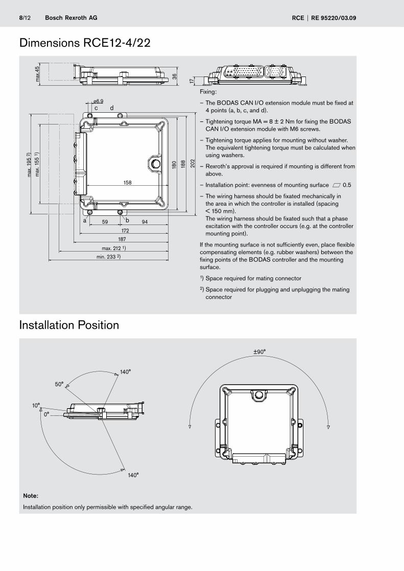
Dimensions RCE12-4/22
Installation Position
Note:
Installation position only permissible with specified angular range.
Fixing:
– The BODAS CAN I/O extension module must be fixed at 4 points (a, b, c, and d).
– Tightening torque MA = 8 ± 2 Nm for fixing the BODAS CAN I/O extension module with M6 screws.
– Tightening torque applies for mounting without washer. The equivalent tightening torque must be calculated when using washers.
– Rexroth’s approval is required if mounting is different from above.
– Installation point: evenness of mounting surface 0.5
– The wiring harness should be fixated mechanically in the area in which the controller is installed (spacing < 150 mm). The wiring harness should be fixated such that a phase excitation with the controller occurs (e.g. at the controller mounting point).
If the mounting surface is not sufficiently even, place flexible compensating elements (e.g. rubber washers) between the fixing points of the BODAS controller and the mounting surface.
1) Space required for mating connector
2) Space required for plugging and unplugging the mating connector
Bosch Rexroth AGRE 95220/03.09 RCE 9/12
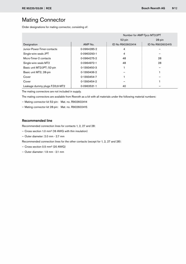
Mating ConnectorOrder designations for mating connector, consisting of:
Number for AMP-Tyco MT2/JPT
52-pin 28-pin
Designation AMP No. ID No R902602414 ID No R902602415
Junior-Power-Timer-contacts 0-0964285-2 4 –
Single-wire seals JPT 0-0963293-1 4 –
Micro-Timer-2 contacts 0-0964275-2 48 28
Single-wire seals MT2 0-0964972-1 48 28
Basic unit MT2/JPT; 52-pin 0-1393450-3 1 –
Basic unit MT2; 28-pin 0-1393436-2 – 1
Cover 0-1393454-7 1 –
Cover 0-1393454-2 – 1
Leakage dummy plugs F.D3,6-MT2 0-0963531-1 40 –
The mating connectors are not included in supply.
The mating connectors are available from Rexroth as a kit with all materials under the following material numbers:
– Mating connector kit 52-pin: Mat. no. R902602414
– Mating connector kit 28-pin: Mat. no. R902602415
Recommended lineRecommended connection lines for contacts 1, 2, 27 and 28:
– Cross section 1.0 mm² (16 AWG with thin insulation)
– Outer diameter: 2.0 mm - 2.7 mm
Recommended connection lines for the other contacts (except for 1, 2, 27 and 28):
– Cross section 0.5 mm² (20 AWG)
– Outer diameter: 1.9 mm - 2.1 mm
10/12 Bosch Rexroth AG RCE RE 95220/03.09
• General instructions: – Reliable operation cannot be guaranteed if samples or prototypes are used in series production machines. – The suggested circuits do not imply any technical liability for the system on the part of Rexroth. – Incorrect connections could cause unexpected signals at the outputs of the controller. – Dangerous malfunctions may result if the control electronics are opened or modified or the wiring repaired without authorization. – In addition, the application-specific documents (connection diagrams, software descriptions, etc.) are to be observed. – To switch off the system in emergencies, the power supply to the electronics must be disconnected with a safety switch. The safety switch must be installed in an easily accessible position for the operator. The system must be designed in such a way that actuating the safety switch ensures safe braking. – System developments, installations and commissioning of electronic systems for controlling hydraulic drives must only be carried out by trained and experienced specialists who are sufficiently familiar with the components used and with the complete system. – Unexpected dangers may be present at the machine during commissioning of the RC. For this reason, before commissioning the system, you must ensure that the vehicle and the hydraulic system are in a safe condition. Make certain that no persons are present in the danger zone of the machine. – No components that are defective or not working properly should be used. If components fail and/or exhibit malfunction, repair must be carried out immediately. – The controller RC warms up above regular ambient temperature during operation. To prevent risks due to high temperatures, it should be attached and protected before it is touched. – Incorrect programming of the RC may create potential sources of danger while the machine is in operation. It is the responsibility of the machine manufacturer to determine dangers of this type in a risk assessment and to bring them to the attention of the end user. Rexroth assumes no liability for risks of this type. – Make sure that the controller configuration does not lead to safety-critical malfunctions of the complete system in the event of failure or malfunction. This type of system behavior may lead to danger to life and/or cause much damage to property.
• Conventional use: – The controller RC is designed for use in mobile working machines provided no limitations / restrictions are made to certain application areas in this data sheet. – Operation of the controller RC must generally occur within the operating ranges specified and released in this data sheet, particularly with regard to voltage, temperature, vibration, shock and other described environmental influences. Use outside of the specified and released boundary conditions may result in danger to life and/or cause damage to components which could result in consequential damage to the complete system. – Damages which result from improper use and/or from unauthorized, unintended interventions in the device not described in this data sheet render all warranty and liability claims with respect to the manufacturer void.
• Notes on the installation point and position: – Do not install the controller near parts which generate considerable heat (e.g. exhaust). – Install the controller in such a way that the connector is pointing downwards. This ensures that any condensation water can drain. – A sufficiently large distance to radio systems must be maintained. – All connectors must be unplugged from the electronics during electrical welding operations. – The controller must not be electrostatically charged, e.g. during painting operations. – Radio equipment and mobile telephones must not be used in the driver's cab without a suitable antenna or near the control electronics. – Cables/wires must be sealed individually to prevent water from entering the controller. – Standing and permanently running water is not permissible in the area of the revolving groove (cover-bottom-connector) and in the area of the pressure compensating element.
• Notes on transport and storage: – Controllers must be stored in mean relative humidity of 60% at a temperature between -10°C and +30°C. Briefly, for 100 hours, a storage temperature range of -20°C to +40°C is permissible. – After a storage time of more than 5 years, the controller must be examined by the manufacturer before it is used. – The controller must not be used if it has been dropped, as damage that is not visible could still affect its reliability.
Safety Notes
Bosch Rexroth AGRE 95220/03.09 RCE 11/12
• Notes on circuitry and on wiring: – The lines used for speed sensors are to be shielded. The shield must be connected to the electronics on one side or to the machine or vehicle ground via a low-resistance connection. – Cables to the electronics must not be routed close to other power-conducting lines in the machine or vehicle. – The electronics and the power outputs of a controller must be fed from the same power source. – The wiring harness should be fixated mechanically in the area in which the controller is installed (spacing < 150mm). The wiring harness should be fixated such that a phase excitation with the controller occurs (e.g. at the controller mounting point). – When wiring the output stages, the maximum cumulative output current for each output stage group should be noted. The cumulative output current means a permanent, simultaneous actuation of the output stages.
• Notes on proportional solenoids and switching solenoids and other switched inductive consumers: – The electronics may only be tested with the proportional solenoids connected. – The proportional solenoids must not be wired with suppression diodes. – Switching solenoids at the outputs of the controller RC do not need to be connected to suppression diodes. – Other inductive loads that are in the system but not connected to the controller RC must be connected to suppression diodes.
Safety features in the RCE
– Faults in the supply voltage are detected by internal monitoring.
– All output signals can be monitored by the microcontroller with the appropriate software.
– For service purposes, the controllers can be operated with all power outputs de-energized.
– The internal watchdog module centrally switches off all proportional and switched outputs in the event of disturbances to the program execution.
Product-specific notes
– Via the release input, the output stages (proportional and switched outputs) are switched off independent of the CAN bus.
Safety Notes
© This document, as well as the data, specifications and other information set forth in it, are the exclusive property of Bosch Rexroth AG. It may not be repro-duced or given to third parties without its consent.
The data specified above only serve to describe the product. No statements concerning a certain condition or suitability for a certain application can be de-rived from our information. The information given does not release the user from the obligation of own judgment and verification. It must be remembered that our products are subject to a natural process of wear and aging.
Subject to change.
Bosch Rexroth AG HydraulicsMobile ElectronicsGlockeraustrasse 4 89275 Elchingen, Germany Phone +49 (0) 73 08 82-0 Fax +49 (0) 73 08 [email protected] www.boschrexroth.com/mobile-electronics
12/12 Bosch Rexroth AG RCE RE 95220/03.09

![03.09 Handover Procedures]](https://static.fdocuments.net/doc/165x107/577d29771a28ab4e1ea6df5d/0309-handover-procedures.jpg)