
Booklet - Teachers - Bross · PDF file3 Light Experiment Introducingthe LDR ... relationship...
34
BROSS Computing Maker’s Kit TEACHER’S GUIDE The teacher’s guide for the Maker’s Kit runs through lesson ideas and plans for using the BBC Micro:bit with the Maker’s Kit, including quizzes, homework ideas, and learning objectives for each task.
Transcript of Booklet - Teachers - Bross · PDF file3 Light Experiment Introducingthe LDR ... relationship...

BROSSComputing
Maker’s KitTEACHER’S GUIDE
The teacher’s guide for the Maker’s Kit runs through lesson ideas and plans for using the BBC Micro:bit with the Maker’s Kit, including quizzes, homework ideas, and
learning objectives for each task.


Preliminary
Application with the National CurriculumThe Maker’s kit, and accompanying documentation, has been designed to meet some of the needs of the Key Stage 3 (targeting year 7) Computing Curriculum, whilst remaining engaging and accessible to pupils. This documentation specifically includes the following key ideas:• Introduction to fundamental principals, including algorithms and analogue / digital
devices• Analysing computational problems• Applying practical experience to write computer programs to solve a problem• Evaluation and design of the usage of particular components and technologies
These lessons act as an engaging introduction to the concepts of computing and programming. They allow students to meet some of the key goals of the national curriculum, specifically:Ø design, use and evaluate computational abstractions that model the state and
behaviour of real-world problems and physical systems Ø understand the hardware and software components that make up computer
systems, and how they communicate with one another and with other systems Ø undertake creative projects that involve selecting, using, and combining multiple
applications, preferably across a range of devices, to achieve challenging goals, including collecting and analysing data and meeting the needs of known users
These lessons also introduce key concepts of the computing curriculum – including an introduction to programming, an introduction to basic electronics and electrical theory, and an introduction to computational thinking (for example, algorithms).
PrerequisitesThe Maker’s Kit is an expansion kit for the BBC Micro:bit, used to further student’s interactions with the computing curriculum by allowing them to create more tactile and engaging programs with the Micro:bit. Before using the kit, students should have some knowledge of the Micro:bit – for example, it may be practical for students to have worked through the official Block Editor Lessons (https://www.microbit.co.uk/blocks/book) , specifically lessons 1 and 2 which introduce the Micro:bit. This series of lessons focusses on the real-world applications of computing, and will teach students about electrical components, interaction of code with the real-world, and real-world applications of programs. The lessons will also engage students by encouraging experiments and collaboration.

Key Ideas
Key Idea 1: Micro:bit Pins
The Micro:bit is able to connect to electrical components by the pins on the bottom of the board. This allows us to code extra things with the Micro:bit, for example allowing it to play sound. We can get information from a component (input) or program a component to do something (output).
Ensure students are aware of these key ideas before engaging with the lessons:
Key Idea 2: Current and Resistance• An electric current is the flow of electric charge – when charge is applied to a
component, a component does something. For example, when we apply charge to an LED it glows. The Micro:bit is able to send current to components attached via the pins.
• Resistance is when a material or device reduces the electric current that flows through it. We can make an analogy to water pipes; if the resistance is bigger the pipe is thinner and water flow is decreased. Different components have a different resistance. The Micro:bit is able to measure resistance of a component (input).
Key Idea 3: Coding the BBC Micro:bitPrior knowledge of writing code for the BBC Micro:bit is required. This guide explains key concepts of programming for the Micro:bit and so is applicable to all of the editors.
Block Editor
JavaScript Code Kingdoms
TouchDevelop
Above is the same program in three editors, which turns on pin 12 (red colour bi-colour LED)

Summary
# Lesson Title Summary Key Words Key Skills
1 The Basics Introduction to the Maker’s Kit, encouraging students to familiarise themselves with the board & begin to code
it.
- ü Understanding how the Micro:bit and Maker’s Kit
interfaceü Understanding the idea of
physical components interacting with digital code
2 Algorithms Encouraging students to create their own algorithms
in the form of a song
• Piezo Sounder• Algorithm
ü Understanding the piezocomponent
ü Introduction of the key term “algorithm”
ü Reading and creating algorithms in the form of
musical pieces
3 Light Experiment Introducing the LDR component. Students
launch their own experiment to find the relationship between
resistance and light intensity
• Light Dependent Resistor
• Analogue • Digital• Input• Output
• Resistance• Light intensity
ü Understanding the concept of “digital” and “analogue”
ü Understanding the concept of “input” and “output”
ü Understanding the LDR component
ü Devising and conducting an experiment
ü Independence in relation to computational thinking;
devising a conclusion based off of evidence
4 Smart Plant Sensor Project
This lesson revolves around the creative project of creating a smart plant
sensor, building upon the knowledge from lesson 3
- ü To design and develop a creative project using
technologyü To understand real-world
application of codeü To meet a design brief
5 Bi-Colour LED This lesson introduces the bi-colour LED, and tests
students on their practical application of the skills
learnt so far.
• Light Emitting Diode• Bi-Colour
ü Understanding the bi-colourLED component
ü Applying skills learnt so far
6 Rotary Potentiometer &
Research Task
This lesson introduces the rotary potentiometer
component. The lesson also includes a research task for
students to consolidate their knowledge so far and to investigate real-world
uses of the components of the Micro:bit and the
Maker’s Kit.
• Rotary Potentiometer• Variable resistor
ü Understanding the rotary potentiometer component
ü Understanding real-world applications for various electrical components

Summary
# Lesson Title Summary Key Words Key Skills
7 Project Planning This lesson revolves around the importance of planning,
and coding a large and complex program for the
Micro:bit.
- ü Planning a project as a solution to a particular
problemü Code a complex program
for the BBC Micro:bit
Extra Resources• Breadboarding in class• Micro:bit and Maker’s Kit recipes• 23 pages of additional code projects for the Micro:bit
Note• These resources have been designed parts around the KS3 computing curriculum,
targeting year 7s. However, with additional guidance, it is possible to apply these lessons (as well as the extra code projects) to other years.

Lesson 1: The Basics
PrerequisitesBefore starting to use the Maker’s Kit it is vital that students have been introduced to the BBC Micro:bit and have some experience writing code using either the Block Editor or Touch Develop, as well as basic knowledge of the Micro:bit’s pins. Tutorials and lesson plans for this can be found online at https://www.microbit.co.uk/create-code
The Micro:bits in the class should also be running the introduction script from the Maker’s Kit website.
Lesson Objectives• To connect and test the Maker’s Kit for BBC Micro:bit• To be able to code the Micro:bit pinsThe LessonRemind students of the pins on the Micro:bit, and how they allow connection to other components (such as an LED) to allow the Micro:bit to do more (e.g. play sound). Next show students the Maker’s Kit board and point out each of the key features (use the map on page 2 for details on each component). Explain that the board allows students to code extra components without needing to learn electronics.
Hand out the boards and ask students to connect them to the Micro:bit by screwing in all 5 of the screws. Refer to page 3 of the Maker’s Kit Student Booklet. When students connect a battery or plug in their Micro:bit, the introduction script should run and the following should happen:• The LED changes colour as the Micro:bit plays different sounds• After, the sound of the device will change• As you move your hand closer to the board the sound changes• By twisting the rotary potentiometer the colour of the LED changes
Explain how each of the components of the board allow this to happen:• The piezo plays sounds• The rotary potentiometer allows you to change the colour of the bi-colour LED• The light dependent resistor (LDR) changes the pitch of the piezo

Lesson 1 Activity
Ask students to login to microbit.co.uk and edit the introduction script, manipulating the variables with their own knowledge and seeing how this translates on the board.
The Micro:bit should be running the aforementioned introduction script from the Maker’s Kit website, which introduces all of the components:Ø The LED changes colour as the Micro:bit plays different sounds (bi-colour LED &
piezo)Ø After, the sound of the device will changeØ As you move your hand closer to the board the sound changes (LDR)Ø By twisting the (rotary potentiometer) the colour of the LED changes
Once students have connected the board to the Micro:bit, give them free reign to modify the introductory script. Prompt them to explore what happens when they modify the script by:• Adding ‘wait’ instructions• Changing the pin that the code applies to• Using the Micro:bit LEDs at the same time• Changing the amount of loops on the first melody• Adding extra sounds and code blocks
ChallengeChallenge students to draw a map of how the Maker’s Kit corresponds to the BBC Micro:bit. See if they are able to find out which pin of the Micro:bit controls each component, and see if they are able to identify the functions of each component. Students could record their findings in a table similar to the one below:
Draw a picture of the component
What does it do? What do you think it is called?
What pin is it controlled by?
Makes noise Piezo Sounder 0
Detects light intensity
Light Dependent Resistor
1
Glows red, yellow, or green
Bi-Colour LED 12(red), 16(green)
Gives a number to the Micro:bit
Rotary Potentiometer
2

Lesson 2: Algorithms
PrerequisitesStudents have worked through Lesson 1
Lesson Objectives• To understand the piezo component• To code the piezo component• To understand what an algorithm is
The LessonShow students the piezo component on the underside of the board and explain that when an electrical current is put across it the piezo vibrates and it plays sound. Explain that it is connected to pin 0 on the Micro:bit. Introduce the “Music” section of the Block Editor / Touch Develop. Refer to page 4, asking students to test the piezo by coding a simple tune to play when the A button is pressed.
Allow students time to experiment to create sounds and songs with the piezo. Refer to page 5 of the booklet to explain all of the “Music” blocks (Block Editor).
Ask students to think of possible uses for the Micro:bit when it can play sound. Below are a few ideas you might want to share:• Use the accelerometer to create a Micro:bit alarm • Create an audible notification system when your phone gets a notification, using
the bluetooth functionality• Simon says game, where the player follows the instructions on the board• Add sound effects and music to your games• Create a Micro:bit Arpeggiator• Proximity Sensor
Introduce the concept of an algorithm: a series of instructions followed by a device to carry out a particular task. Explain that, when they write a song, each note is a single instruction in the algorithm and the entire algorithm plays a song.
Key Terms• Algorithm
• Piezo Sounder
Lesson 2 Activity
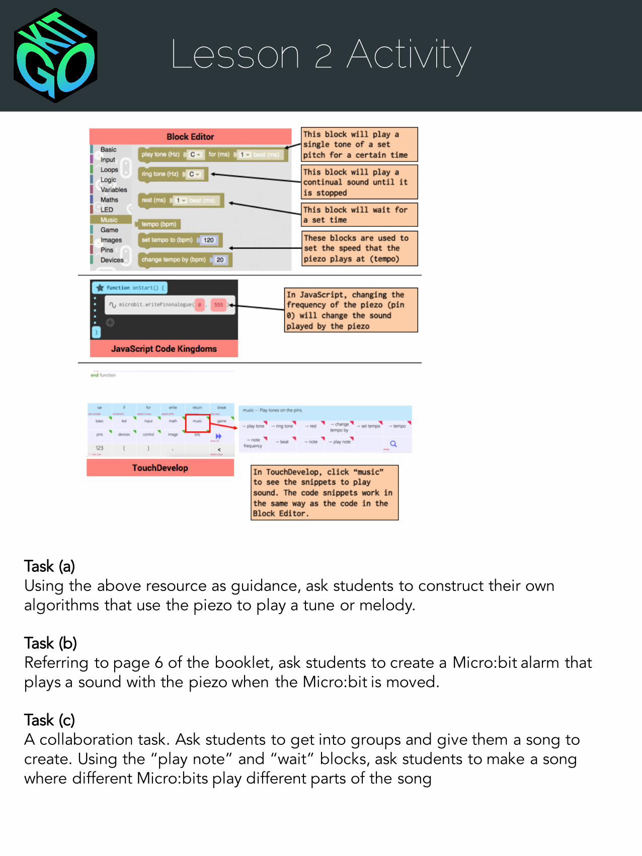
Task (a)Using the above resource as guidance, ask students to construct their own algorithms that use the piezo to play a tune or melody.
Task (b)Referring to page 6 of the booklet, ask students to create a Micro:bit alarm that plays a sound with the piezo when the Micro:bit is moved.
Task (c)A collaboration task. Ask students to get into groups and give them a song to create. Using the “play note” and “wait” blocks, ask students to make a song where different Micro:bits play different parts of the song

Lesson 3: Light Experiment
PrerequisitesStudents have worked through Lesson 2
Lesson Objectives• To understand what an LDR is• To understand digital and analogue input /output• To understand the difference between output & input• To understand the function of an LDR• To code a project using the LDR
Digital V AnalogueWe can output either as digital or as analogue; digital is off or on, which is also known as binary (0 or 1). Analogue output can be any value – in the case of the Micro:bit, between 0 to 1024. As a result, an analogue component can be in many different states; for example, the brightness of LEDs or the sound played by a piezo.
Inputs can also be classified the same way – a digital input has two states, for example a simple button is on or off (like those attached to the Micro:bit). Analogue inputs have a range of states, from 0 to 1024 – these are generally used for sensing, for example with the LDR on the board the analogue input will change based on the strength (intensity) of light around it.
LIGHT INTENSITY
RESISTANCE
Detecting lightWe detect light using the Light Dependent Resistor (LDR) attached to the board (pin 1).
An LDR changes resistance based on the light levels, as per the graph to the left – so we can find whether a plant has good or bad levels of light by finding the right resistance for bright and dull lights.
The LessonAsk students to read page 7 of the booklet (below) and quiz them on the following key ideas, either by class discussion or using the quiz on the next page.
Key Terms• Light Dependent
Resistor• Analogue • Digital• Input• Output• Resistance
• Light intensity

Lesson 3: Light Experiment
The Lesson ContinuedAsk students to test the LDR by writing code that displays the value of the LDR on the screen. This is as simple as “forevever: show number (analogue read pin:1)
Ask students to play around to see how holding the Micro:bit near different light sources changes the value from the LDR. Next, ask students to come up with some project ideas using the LDR. Ask for an application of an LDR in the real world; for example automatically turning on streetlamps.
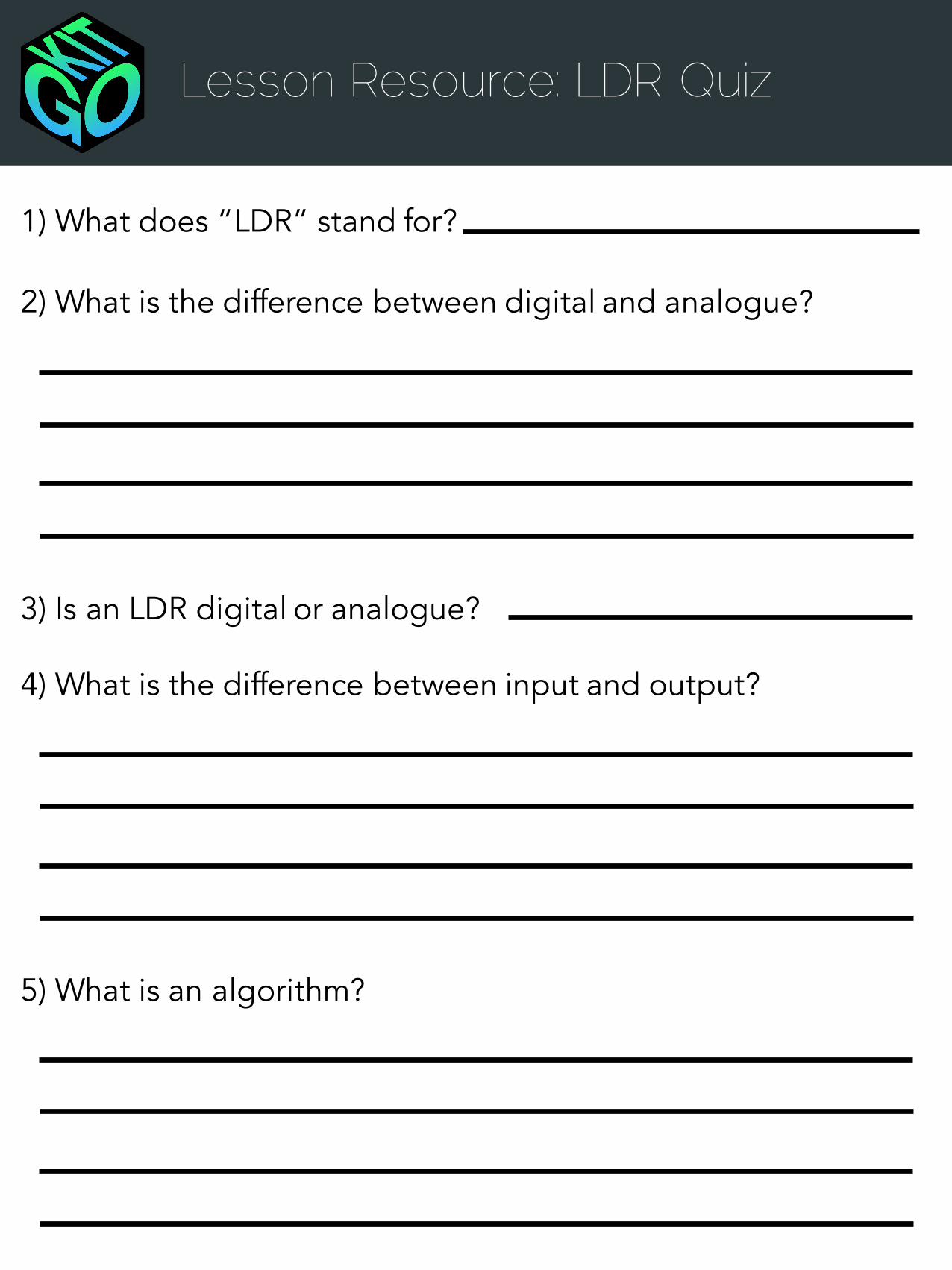
Lesson Resource: LDR Quiz
1) What does “LDR” stand for?
2) What is the difference between digital and analogue?
3) Is an LDR digital or analogue?
4) What is the difference between input and output?
5) What is an algorithm?
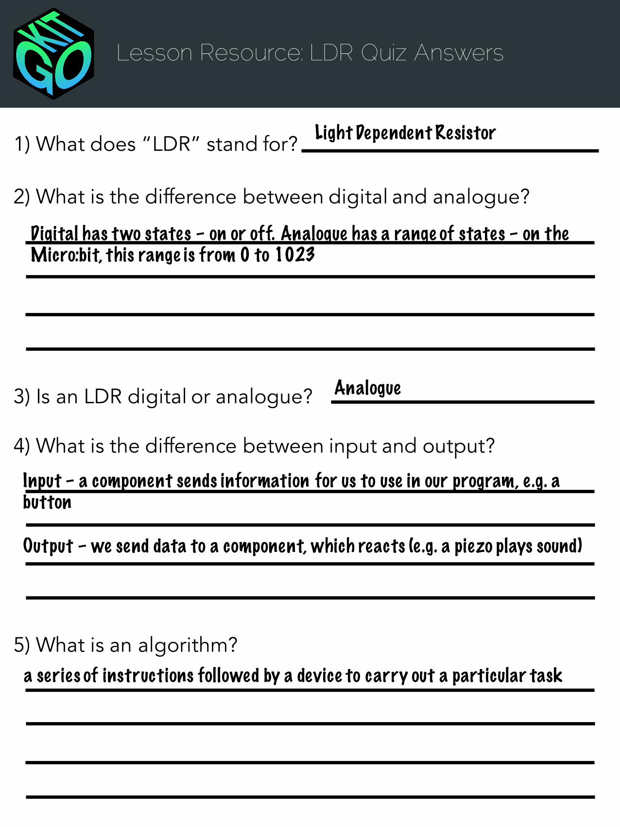
Lesson Resource: LDR Quiz Answers
1) What does “LDR” stand for?
2) What is the difference between digital and analogue?
3) Is an LDR digital or analogue?
4) What is the difference between input and output?
5) What is an algorithm?
Light Dependent Resistor
Digital has two states – on or off. Analogue has a range of states – on the Micro:bit, this range is from 0 to 1023
Analogue
Input – a component sends information for us to use in our program, e .g. a button
Output – we send data to a component, which reacts (e .g. a piezo plays sound)
a series of instructions followed by a device to carry out a particular task

Light Experiment Activity
Ask students to conduct an experiment to find the relationship between distance from a lamp (light intensity) and resistance of an LDR. Ask students to plan their own results table and method, or to use the example practical experiment below. This activity teaches students to conduct an experiment and use their own conclusion in their programs (see the plant sensor activity)
Distance of lamp LDR resistance
No light
100 cm
50 cm
25 cm
1. Explain the idea of an LDR (changing light intensity changes resistance or value of the LDR)
2. Ask students to create a program that displays the value on the LDR3. Create a class discussion on how to measure light intensity and the value on the
LDR4. Draw up a results table and method as a class (moving a lamp closer to the
Micro:bit in a dark room and recording the value the Micro:bit displays)5. Ask students to collect results for a number of distances
6. Extension tasks:1. Plotting a graph (in Microsoft Office Excel or on paper)2. Writing a concluding statement on the relationship between light intensity and
the value of the LDR3. Plotting possible uses of this, for example if we know the resistance of the LDR
when the room is completely dark we could use this to turn lights on

Light Experiment Plan
The QuestionWe know that changing the intensity of light will change the value that the LDR gives to the Micro:bit (the resistance). We want to know – how does a changing light intensity affect the resistance of an LDR?
PreliminaryA program must have been written (and must be running on the Micro:bit) that displays the resistance of the LDR on the Micro:bit LEDs.
Equipment• A lamp or torch• Micro:bit with Maker’s Kit• Power supply for the Micro:bit• Results table• 1 metre ruler• Small Box• Sticky Tape
Task1. Set up the apparatus as shown below:
2. In a dark room:1. Place the light source at the end of the 1 metre ruler and record the value on
the Micro:bit LEDs in the results table2. Repeat from 80cm to 0cm, for every 20cm
3. Plot a graph of the results4. Answer the following questions:
1. Why might covering up the Micro:bit LEDs make the results more accurate?2. What can you say about the relationship between resistance and light
intensity?3. What would you say is a good representation of the resistance for:
a) A sunny day? b) Dark night? c) a cloudy evening?
Ruler
Light Source
Micro:bit and Maker’s Kit, with power supply connected – stuck to the side of the box with the tape so the top of the LDR is facing the light source.

Template Results
Distance of lamp LDR reading
No light
1000cm
800cm
600cm
400cm
200cm
0cm
Results Table
Graph of Results
DISTANCE OF LAMP (cm)
LDR READING

Lesson 4: Plant Sensor
The Lesson• Students will design and create a solution to a specific problem• Students will research to ensure their solutions answer the problems presented in
the brief• Students will apply their knowledge of physical components of the Maker’s Kit and
the BBC Micro:bit as well as their experience as coders
Using the Activity sheet, students should design and create a solution to the following brief:
Creative ProjectThis lesson revolves around the creative project of creating a smart plant sensor. Students must have completed the Light Experiment from Lesson 3.Lesson Objectives• To design and develop a creative project using technology• To understand real-world application of code
The BriefAndrew has no knowledge of plants yet he is given a Peace Lily for his birthday.He has no idea of what temperature to leave the plant in or where to leave it so it gets the right amount of sunlight. Create a smart plant detector, so Andrew is told when the plant is in poor conditions by the plant itself.Ø Plan, design, and create a smart plant sensor that monitors light and
temperature
The activity is split into the following:• Reading and understanding the brief• Researching the problem• Designing a solution• Coding a solution• Testing and analysing their solution
Students should be given the Activity sheet and should create their own solutions to the problem, working in groups or independently.
Alternatively, students can follow the activity on pages 9 and 10 of the student guide to create their own smart plant sensor.

Lesson 4 Activity
The BriefAndrew has no knowledge of plants yet he is given a Peace Lily for his birthday.Hehas no idea of what temperature to leave the plant in or where to leave it so it gets the right amount of sunlight. Create a smart plant detector, so Andrew is told when the plant is in poor conditions by the plant itself.Ø Plan, design, and create a smart plant sensor that monitors light and temperature
ResearchUse the internet to research and answer the following questions. The results will be useful in creating a plant sensor that is optimal for a specific plant (a Peace Lily).
1. What light levels are best for a Peace Lily?
2. What is a good range of temperatures for a Peace Lily?
3. Below what temperature would be too cold for one?
4. There does not need to be an indicator for water levels of the Lily. Why is it obvious when the plant needs watering?
DesignUsing the above research, and your findings from the LDR experiment, fill in what you think would be a suitable set of values for your plant sensor.
Temperature
Too cold below this temperature
Too hot above this temperature
Light Level (LDR Resistance)
Too dark below this value

Lesson 4 Activity
Programming TaskUsing the values from the previous page, write a program that will alert the user when the plant is in poor conditions. This alert must contain a visual element, and could also contain an auditory alert using the piezo sounder.
Use the code below if you get stuck – however, you cannot copy the code as it is as the values will not be the values for temperature and light level that you decided were best for the Peace Lily.
Block Editor Touch Develop Code
Reflection1. How could your design by altered for a different type of plant?
2. If you were to redesign your system for a blind person, what might you add?
3. Did your design meet the needs of the brief? Why / why not?

Lesson 5: Bi-Colour LED
PrerequisitesStudents have worked through Lessons 1, 2, and 3Lesson Objectives• To understand what an LED is• To understand what a bi-colour LED
The LessonPoint out the bi-colour LED on the board. Explain that an LED is a Light-Emitting Diode that glows when a current is applied to it. Explain that there are 25 red LEDs already on the Micro:bit. Explain that a bi-colour LED can glow two different coloursin one LED, and different LEDs glow different colours. The LED on the Maker’s Kit can glow green, red, and yellow (green + red).
Ask students to create small programs using the bi-colour LED to glow different colours in different patterns. Introduce the information below so students are aware of how to program to LED to glow different colours:
Key Terms• Light Emitting Diode
• Bi-Colour
A standard LED (Light-Emitting Diode) glows when a current is applied to it. A bi-colour LED can glow different colours, depending on the leg across which current has been applied. On the Maker’s Kit the bi-colour LED is attached to pins 12 and 16:
• Pin12 = ON• Pin16 = OFF• Colour = RED
• Pin12 = OFF• Pin16 = ON
• Colour = GREEN
• Pin12 = ON• Pin16 = ON• Colour =
ORANGE
Students should try to create the following programs:1. Traffic Light à When the ‘a’ button is pressed, the LED shows glow red, then
yellow, then green, with appropriate pauses2. Modifying their previous programs with the piezo sounder (or creating them if
they haven’t already), students should add the bi-colour LED so it changes colouron every different pitch of the piezo
3. A and B à When the ‘a’ button is pressed, pin12 turns on. When the ‘b’ button is pressed, pin16 turns on. When both are pressed, both pins turn off.

Lesson 6: Rotary Potentiometer
PrerequisitesStudents have worked through all previous lessons and have a suitable understanding so far.Lesson Objectives• To understand what a rotary potentiometer is• To plan a code projectThe LessonShow students to rotary potentiometer on the board and remind them of the difference between analogue and digital components – quiz their prior knowledge to see if they understand that the rotary potentiometer is an analogue input component.
Tell the students that the rotary potentiometer is a form of variable resistor – by twisting the knob they can change the resistance given to the Micro:bit and provide number input. Ask them to suggest ways this has a real life application and how they will integrate it into their Micro:bit projects; they may discuss volume controls or lights with a fade control, for example.
Tell students to write some simple code that displays the number from the rotary potentiometer on the Micro:bit – make sure they are aware it is connected to pin 2. As an extension, ask students to replicate the program on page 11 of the student booklet, to change the brightness of the Micro:bit LEDs when the potentiometer is twisted:
Key Terms• Rotary Potentiometer• Variable resistor
Touch Develop Code
Block Editor
Tasksa) Students can change any programs they have written so far to use the rotary
potentiometer in some wayb) Using the Activity sheet, students can research real-world uses of the components
of the Micro:bit and Maker’s Kit.

Lesson 6 Activity
Research ActivityStudents should answer the following questions for each of the components on the Maker’s Kit. Students may use the internet to research the real-world applications of the components.
1. What does the component do?2. Is it analogue or digital?3. Is it input or output?4. Give 2 real-world applications of the component5. Write a small program demonstrating the use of the component
• Piezo Sounders• Light Dependent Resistors• LED’s and Bi-Colour LEDs• Rotary Potentiometers
Students can fill in their answers on the Research Activity Sheet.

Research Activity Sheet
Component Name
Pin What does it do?
Analogueor
Digital?
Input or Output?
Real-World Application
Piezo Sounder
Light Dependent Resistor
Bi-ColourLED
Rotary Potentiometer
Component Name What does it do?
Analogue or Digital?
Real-World Application
Compass
Accelerometer
Temperature Sensor
Maker’s Kit
Micro:bit

Research Activity Answers
Component Name
Pin What does it do?
Analogueor
Digital?
Input or Output?
Real-World Application
Piezo Sounder
0 PlaysSound
Can be both
Output • Alarm Clock• Device Notifications
Light Dependent Resistor
1 Detects LightIntensity
Analogue Input • Motion sensor for alarm• Automatic streetlight
Bi-ColourLED
12 & 16
Glows Redand Green
Digital Output • Status indicator• Power indicator
Rotary Potentiometer
2 Sends a number to the device
Analogue Input • Volume Control• Light Dimmer Switch
Component Name What does it do?
Analogue or Digital?
Real-World Application
Compass Detects the heading of the Micro:bit(North/South)
Analogue • A digital version of a compass- navigational
Accelerometer Detects the tilt of the Micro:bit
Analogue • Navigation systems• Racing Games
Temperature Sensor
Detects the temperature
Analogue • Smart plant monitor• Weather station
Maker’s Kit
Micro:bit

Lesson 7: Project Planning
PrerequisitesStudents have worked through all previous lessons and have a suitable understanding so far.Lesson Objectives• To plan a project with the Micro:bit• To code a complex program for the Micro:bit
The LessonThis lesson revolves around the importance of planning, and coding a large and complex program for the Micro:bit.
Before starting you may want to quiz students on their knowledge of the Micro:bit so far with the quiz on the next page.
Ask students (either in groups or individually) to plan a project using at least two components of the Maker’s Kit board and at least three components of the Micro:bit. Refer to pages 13, 14, and 15 in the student booklet for inspiration.
Micro:bit• 25 LEDs• 2 buttons• Compass• Accelerometer• Bluetooth• Temperature sensor
Maker’s Kit• Bi-Colour LED• Piezo Sounder• Rotary
Potentiometer• Light Dependent
Resistor
Once students have planned their projects, ask them to code them. Students could also create a presentation for the class demonstrating their project for the Micro:bit. They could explain the functionality, demonstrate their program, and explain possible commercial uses of the project (for example as a smart watch).
Students could be assessed on their overall proficiency in using the Micro:bit for further purposes. An assessment on their ability to collaborate with others, on understanding the uses of the Micro:bit and Maker’s Kit components, and on planning and creating code for the Micro:bit.

Lesson Resource: Micro:bit Quiz
1) What is a piezo sounder?
2) What is an algorithm?
3) Jenny wants to create a Simon Says game. What components could she use fora) A volume control?b) A power indicator?c) Playing a sound?
4) What is the difference between digital and analogue?
5) Give three features of the Micro:bit and a possible use for each one.1)2)3)
6) Draw every LED that is ON after running this code:

Micro:bit Quiz Answers
1) What is a piezo sounder?
2) What is an algorithm?
3) Jenny wants to create a Simon Says game. What components could she use fora) A volume control?b) A power indicator?c) Playing a sound?
4) What is the difference between digital and analogue?
5) Give three features of the Micro:bit and a possible use for each one.
6) Draw every LED that is ON after running the code
An electrical output component that vibrateswhen a current is applied to it, causing it to make a noise .
A series of instructions carried out to perform aparticular task.
Rotary PotentiometerBi-Colour LEDA Piezo Sounder
Digital is e ither on or off. An analogue component can be in a range of states
Compass – detecting Micro:bit heading (e .g. a Micro:bit compass)Accelerometer – detecting tilt (e .g. a virtual spir it level)Bluetooth – sending or receiving data wirelessly (e .g. a smartwatch) Button – getting user’s input (e .g. Micro:bit calculator)LEDs – displaying graphics and visual feedback (e .g. a game)Pins – connecting additional components (e .g. an LED)Temperature sensor – detecting heat (e .g. an e lectronic thermometer)

Project Planning Sheet
Name of project:
Write a brief overview of what the program will do and what problem it will solve.
Think of a problem you face in your life, and how you could code a solution to it.
What components will you use in this program?
Now code your program and test it on the Micro:bit. Evaluation:
Does your program work as you originally designed? Why / why not?
What problems did you face when writing your program?

Project Planning Sheet
What editor was your program written in?
Demo your program to a classmate. Ask them to give some feedback here.
Explain how you might change your program to act on this feedback.
If you had infinite resources at your disposal, what might you add to your project to make it better?
Create a presentation demonstrating your program, ensuring it answers all of the above questions. You should also include how your program would be used in the
real world and how your program works.
Breadboarding in class
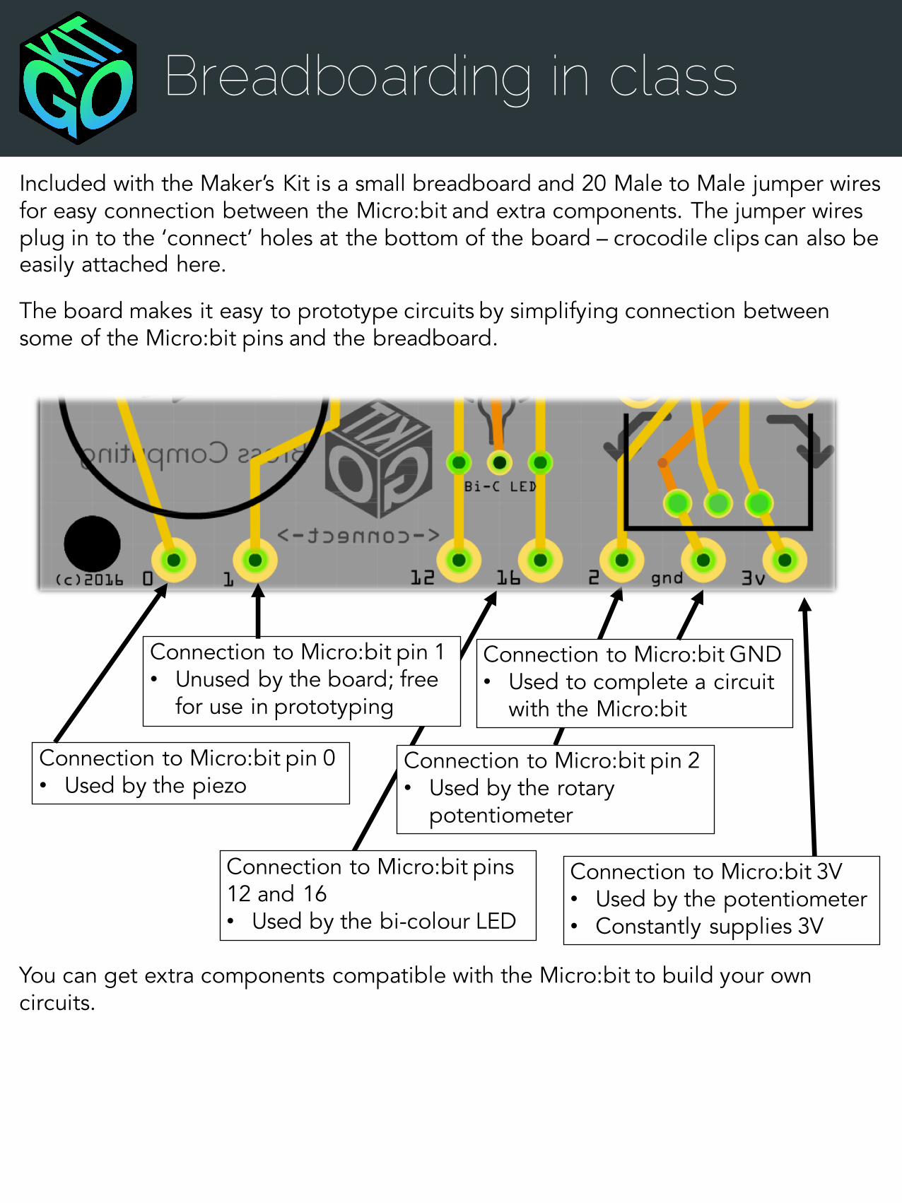
Included with the Maker’s Kit is a small breadboard and 20 Male to Male jumper wires for easy connection between the Micro:bit and extra components. The jumper wires plug in to the ‘connect’ holes at the bottom of the board – crocodile clips can also be easily attached here.
The board makes it easy to prototype circuits by simplifying connection between some of the Micro:bit pins and the breadboard.
Connection to Micro:bit pin 0• Used by the piezo
Connection to Micro:bit pin 1• Unused by the board; free
for use in prototyping
Connection to Micro:bit pins 12 and 16• Used by the bi-colour LED
Connection to Micro:bit pin 2• Used by the rotary
potentiometer
Connection to Micro:bit GND• Used to complete a circuit
with the Micro:bit
Connection to Micro:bit 3V• Used by the potentiometer• Constantly supplies 3V
You can get extra components compatible with the Micro:bit to build your own circuits.

Recipes
Take a look at some of the ways students can combine components of the Maker’s Kit:
+LDR Piezo
àHand Sensor
Set the frequency of the sound from the piezo to the value from the LDR. As you move your
hand closer to the board the pitch will change!
+Piezo à
Pitch ControlUse the potentiometer to vary the sound
played by the piezo by setting the frequency of the piezo to the value of the potentiometerPotentiometer
+ àGlowing Light
Use “if” statements to change the colour of the LED based on the rotation of the potentiometer
Potentiometer LED
+ àColour Experiment
Vary the colours of the LED in a dark room. Does the value of the LDR change based on
the colour? What colour is the brightest?
+ àLight Display
Code the piezo and LED to work in unison, creating a strobe light display for a tune played
by the device
LED LDR
Piezo LED
à There are examples of how to use these components in the activities in the student / activity booklet, which can be found at http://www.bross.tech/downloads

ActivitiesNow students have a good understanding of the Maker’s Kit, they may want to try to code some of the following activities. These activities can be found in the student / activity guide at http://www.bross.tech/downloads
Alarm Difficulty: IntermediateFollow the challenges to edit the Micro:bit alarm program, adding more functions. Write a program that locks your Micro:bit, requiring the correct pin from the rotary potentiometer to unlock.
Block Editor & Touch Develop
Code Challenge Difficulty: EasyChallenge to write a program using all of the components on the board in a fun and interesting way. Try planning a program before coding and testing it on the Maker’s Kit and Micro:bit.
Any Editor
Test ChallengeChallenge to write a program using all of the components on the board in a fun and interesting way. Try planning a program before coding and testing it on the Maker’s Kit and Micro:bit.
Difficulty: IntermediateBlock Editor & Touch Develop
Pixel Shooter GameStep by step programming on how to create a shooter game for the Micro:bit and Maker’s Kit in the Block Editor. The finished product features a character, an enemy, a barrier, and a score system – and uses the rotary potentiometer, bi-colour LED, and buttons.
Difficulty: ChallengingBlock Editor
Simon Says Difficulty: ChallengingCode a Micro:bit version of “Simon Says” – the player has to copy the action on the Micro:bit screen or lose a life! Uses the components of the Maker’s Kit to improve gameplay, for example audio when a mistake is made.
Block Editor
Pixel Shooter ChallengesA list of challenging tasks for the Pixel Shooter code. Follow the tasks to add more features to the program without the guidance of the booklet. Compare your code to the solutions on the website.
Difficulty: Very HardBlock Editor

BROSSComputing
Maker’s Kit
Maker’s Kit © Bross Computing LimitedMicro:bit © Copyright Micro:bit Educational Foundation
Block Editor © MicrosoftTouchDevelop © Microsoft
Written by Ross LoweAdditional material by Stuart Ball
bross.tech


