MAYA N - Cotton House Hotel · MAYA N . Created Date: 4/8/2015 6:55:39 PM

R
Learning Maya
booklet_new 11/7/02 2:39 PM Page 1

This material ("Material") is copyrighted (c) 2002 Alias|Wavefront, a division of Silicon GraphicsLimited ("Alias|Wavefront") and contains proprietary and confidential information of Alias|Wavefront.The Material is protected by national and international intellectual property laws and treaties. Allrights reserved.
THE MATERIAL IS PROVIDED "AS IS" AND ALIAS|WAVEFRONT DOES NOT WARRANT THATTHE MATERIAL WILL MEET YOUR REQUIREMENTS OR THAT THE CONTENTS OF THEMATERIAL ARE ACCURATE OR COMPLETE. CONTENTS ARE SUBJECT TO CHANGEWITHOUT NOTICE. ALIAS|WAVEFRONT MAKES NO WARRANTIES, EXPRESS, IMPLIED ORARISING BY CUSTOM OR TRADE USAGE RELATING TO THE MATERIAL, AND WITHOUTLIMITING THE GENERALITY OF THE FOREGOING, SPECIFICALLY DISCLAIMS ANY IMPLIEDWARRANTIES OF TITLE, NON-INFRINGEMENT, MERCHANTABILITY OR FITNESS FOR APARTICULAR PURPOSE. NEITHER ALIAS|WAVEFRONT NOR ITS AFFILIATES, PARENTCOMPANIES, LICENSORS OR SUPPLIERS SHALL HAVE ANY LIABILITY IN CONTRACT, TORTOR OTHERWISE ARISING OUT OF OR IN CONNECTION WITH THE MATERIAL.
(c) 2002 Alias|Wavefront, a division of Silicon Graphics Limited. All rights reserved. TheAlias|Wavefront logo is a registered trademark and Alias|Wavefront, the Alias|Wavefront Education logo, Learning Maya,and the Maya logo are trademarks of Alias|Wavefront, a division of Silicon Graphics Limited. Maya is a registered trademark of Silicon Graphics, Inc., used exclusively by Alias|Wavefront, a division of Silicon Graphics Limited. All other trademarks mentioned herein are property of their respective owners.
Learning Maya | Beginner’s Guide
booklet_new 11/7/02 2:39 PM Page 2
TM R
TM

Learning Maya | Beginner’s Guide
booklet_new 11/7/02 2:39 PM Page 3
TM

The WorkspaceCreating an animation in Maya involves the manipulation of many graphic elements such as curves, surfaces, colors,and textures. Information about these elements is stored in Maya as numeric values that can be viewed in a numberof different ways. In Maya’s workspace, you can choose how you want to view a scene and access different tools toalter its 3D information. Maya offers several ways of accessing and altering your scene, giving you the flexibility tobuild workflows that best suit the way you work.
Time Slider
The Time Slider shows you the timerange as defined by the range slider,the current time and the keys onselected objects or characters. Youcan also use it to “scrub” through ananimation.
Quick Layout Buttons
The Quick Layout Buttons providepredefined configurations of theMaya workspace. The Right MouseButton over these buttons will alsogive access to more options.(not available in Maya 3.5.1)
Help Line
The Help Line gives a short description of tools and menu items asyou scroll over them in the UI. This bar also prompts you with thesteps required to complete a certain tool workflow.
PanelsThe workspace can be divided intomultiple panels that offer differentways of creating and evaluating your scenes.
Menu Sets
While Maya’s first six menus arealways available, the remainingmenus change depending on whichMenu Set you choose. This helpsfocus your work on related tools.
Menus
Menus contain tools and actions for creating and editingobjects and setting up scenes. There is a main menu at thetop of the Maya window and individual menus for thepanels and option windows.
QWERTY Tools
The “qwerty” hotkeys can be usedto Select (q), Move (w), Rotate (e),Scale (r), and Show Manipulators (t)as well as access the last tool used(y) in the scene.
booklet_new 11/7/02 2:39 PM Page 4

Command Line
This bar has an area to the left for inputting simpleMEL commands and an area to the right for feedback.You will use these areas if you choose to becomefamiliar with Maya’s MEL scripting language.
Channel Box
The Channel Box lets you edit and key values forselected objects.Panels
The workspace can be divided intomultiple panels that offer differentways of creating and evaluating your scenes.
Range Slider
This bar lets you set up the start and end time of thescene’s animation and a playback range if you want tofocus on a smaller portion of the timeline.
Playback
The Playback controls let you move around timeand preview your animations as defined by theTime Slider range.
Characters
The Character Menu lets you define one or morecharacters, then prepare them for being animated.
Status Bar
The Status Bar contains shortcuts for a number ofmenu items as well as tools for setting up objectselection and snapping. A Quick Selection field isalso available that can be set up for numeric input.
Shelf
The Shelf is available for you to set up customized toolsets that can be quickly accessed with a single click.You can set up shelves to support different workflows.Press Shift+Ctrl+Alt when selecting a menu item toadd it to the Shelf.
Layers
Maya has two types of layers. Display Layers areused to manage a scene, while Render Layers areused to set up render passes for compositing. Ineach case, there is a default layer where objectsare initially placed upon creation.
The Hotbox
The Hotbox gives you access to all of Maya’s menu items andtools right at your cursor position. When you press and holddown the Space bar on your keyboard, after a short delay theHotbox appears. The Hotbox is also fully customizable.
booklet_new 11/7/02 2:39 PM Page 5

In Maya, 3D space is measured using three axes that are definedas the X-axis, the Y-axis, and the Z-axis. If you imagine lookinginto a movie screen, the width would be the X-axis, the heightwould be the Y-axis, and the depth would be the Z-axis. In Maya,these axes are presented with X and Z on the ground and Y asthe height. You can find any point in this 3D world by defining a coordinate foreach of the axes. To help you visualize these coordinates, a gridwith axis indicators shows you their orientation.
XYZ Coordinate Space
Transformations
When an object is moved, rotated, orscaled, the XYZ axes are used forreference. An object is moved along,rotated around, or scaled along the chosenaxis line. Values for these transformationsare stored for each of the three axes.
The Ground Grid
To create a ground surface to referenceyour work in XYZ, Maya includes a gridthat maps out an area 24 x 24 units. The Xand Z axes are on the ground and form thelines of the grid. The Y-axis is the height.
Origin
Points in a 3D coordinate system are measuredagainst an origin point. This point is assigned avalue of 0, 0, 0.
Axis indicator
To help you visualize the three axes, each isgiven a corresponding RGB color.
X – red Y – green Z – blue
Y-up and Z-up Worlds
By default, Maya is Y-up where the Y-axis represents the height. Some 3D packages,especially CAD applications, might use Z as theheight. If you import a model from one of thesepackages, you have to either re-orient the modelor set up Maya as a Z-up world.
The axes indicators point in the positivedirection for X, Y, and Z.
booklet_new 11/7/02 2:39 PM Page 6

* Macintosh users use Command or Option key instead of Alt. LMB = Left Mouse Button MMB= Middle Mouse Button RMB = Right Mouse Button
Viewing 3D ScenesWhen building a scene in Maya, you work in three-dimensional space. Orthographicand perspective view cameras offer ways of looking at the objects in your scene asyou work. There are also different display options that change the way objects inyour scene are shaded.
Default ViewsIn Maya, the default views are set as Perspective, Top, Front, and Side. ThePerspective view is a representation of your object in 3D space allowing you to movealong the X, Y, and Z axis. The Top, Front, and Side views are referred to asorthographic views and allow you to move in two dimensions at a time.
Tumble
Rotates the point of viewaround the center of interest.
Alt + LMB
Dolly
Moves the camera in and out .
Alt + RMB
Track
Moves the camera vertically orhorizontally.
Alt + MMB
Default Top View Default Perspective ViewDefault Front View Default Side View
Camera ControlsBy Pressing the Command (Alt on PC) key along with different mouse buttoncombinations, you can navigate the camera in your scene. While the Tumble toolis only used to rotate a 3D perspective view, you can track and dolly in manyother views and editors including the Orthographic, Hypergraph, Hypershade,and Render View.
booklet_new 11/7/02 2:39 PM Page 7

Move Tool
The Move Tool has a handle for eachX, Y, and Z axis and a center handle tomove relative to the view.
Transformations
Rotate Tool
The Rotate Tool has a ring for the X, Y,and Z axes. One ring moves relative tothe view, and a virtual sphere rotatesin all directions.
Scale Tool
With the Scale Tool, you can scalenon-proportionally in X, Y, or Z. You canalso scale proportionally by selectingthe center handle.
Transformations are changes made to an object’s position, orientation, and scale inspace. The Transform node holds all of this information and the Transform manipulatorssuch as the Move, Scale and Rotate Tools are used to transform an object along theX, Y, and Z axes.
ManipulatorsManipulators are used to move, scale, and rotate objects in orthographic and 3D space.Each of the manipulators uses red, green, and blue color handles matching the colors ofthe X, Y, Z locator at the bottom left corner of the view, making it easier to distinguishthe direction of the transformation. These handles are designed to constrain thetransformation to one, two, or three axes at a time, allowing for complete control.
Transformation ToolsTo work quickly and efficiently inMaya, the QWERTY Hotkeys offera fast way to access thetransformation tools. These toolsare located at the top left cornerof the Maya workspace. Select,Move, Rotate, Scale, and theShow Manipulators Tools plus anextra space for the last tool youused, are all a part of the QWERTYtool set.
q w e r t yUse the QWERTY shortcut keys on your keyboard toselect and transform the objects in your scene.
booklet_new 11/7/02 2:39 PM Page 8

Scale Tool
With the Scale Tool, you can scalenon-proportionally in X, Y, or Z. You canalso scale proportionally by selectingthe center handle.
rientation, and scale inhe Transform manipulatorsorm an object along the
orthographic and 3D space.dles matching the colors ofg it easier to distinguish
ed to constrain thecomplete control.
ShadingMaya’s Shading menu offers several options for displaying objects in a scene.Shading can be different for each view panel, allowing geometry to be shown atdifferent levels of complexity. The more detailed a scene becomes, the greater theneed to simplify the objects in it. Although Maya is very good at processing complexlevels of geometry, it is a good idea to view your objects in a less complex shadingmode until you are ready to render or make adjustments to those objects. The defaultshading in Maya is Wireframe.
Wireframe
Wireframe shading isthe default shadingquality in Maya.
Keyboard Shortcut: 4
Smooth Shade
Smooth Shade displaysobjects as smooth surfaceswith surface color andshading properties.Keyboard Shortcut: 5
Display Smoothness
you have a choice of howsmooth the models aredisplayed in your workspace.
Hardware Texturing
Hardware Texturingdisplays smooth-shadedsurfaces with textures.Keyboard Shortcut: 6
Hardware Lighting
Hardware Lighting displayssmooth-shaded surfaces withtextures and lighting.Keyboard Shortcut: 7
Keyboard Shortcut: 1
Keyboard Shortcut: 2
Keyboard Shortcut: 3
booklet_new 11/7/02 2:39 PM Page 9

Modeling with NURBS
Control Vertices
They do not exist on the actual surface but areused to manipulate the shape of the surface.
Spans
A span or segment is the space betweenisoparms at edit points. When creatingsurfaces using Revolve, Primitives, andLoft, or rebuilding them, you can specifythe amount of segments or spans.
Isoparms
Isoparms are lines that represent cross-sections in the U and V directions. Isoparmscan be inserted, removed, used to makecurves, and snapped to. If you select anisoparm that's not a span or section, itdisplays as yellow dots. If you select anisoparm that is a span or section, it displaysas a solid yellow line. This distinction isimportant for some modeling actions.
Surface Origin
Turning on this display option highlightsthe first U and V isoparms (red andgreen) and labels them U and V. It alsodraws a line indicating the surfaceNormal direction (blue).
Hulls
The hull comprises straight linesthat connect CVs. When youselect a hull, you are actuallyselecting all of its associatedCVs. the hull offers a better visualcue for the distribution of CVs in acrowded area.
The majority of the surfacing tools begin with creating curves defining the surface. Insome cases the curves are used to create simple surface which are then rebuilt andmodified by CV manipulation. Other times the curves are used to create much morecomplex surfaces that would be difficult to attain otherwise. To help you understandthe operation of the tools, view the Help Line as you scroll through the menus.
Anatomy of a NURBS SurfaceThe components of the NURBS surface are very similar to those of the NURBS curve,except the edit points are not moveable. NURBS surfaces have CVs, hulls, and spanswhich define the shape of a four-sided surface. NURBS models, whether they areorganic or industrial in nature, generally are made up of several adjoining four sidedpatches. As with the NURBS curve, it is desirable to define surfaces with the fewestevenly spaced isoparms or CVs. As earlier stated, the quality and type of curve willaffect the characteristics of the surface. However, the surface parameterization canbe modified after creation by duplicating the surface curves at the desired locationsand re-lofting.
booklet_new 11/7/02 2:39 PM Page 10

Birail Surface
The Birail Tool creates a surface byusing two or more profile curves that sweep alongtwo rails. The profile curves must intersect the railcurves to create a surface. Profile and rail curvescan be isoparms, curves-on-surface, trimboundaries, or boundary curves of an existingsurface. The advantage of this tool over the Loft isgreater control with the addition of rails.
Fillet BlendSurface
The Fillet Tool creates a seamlessblend between two surfaces. The threetypes are: Circular Fillet, FreeformFillet, and Fillet Blend. These terms arediscussed later in this chapter.
Loft Surface
A Loft surface iscreated when asurface is applied to a series of
profile curves that define aframe. There must be at leasttwo curves or surfaceisoparms, and ideally thesame parameterization for
each curve, to achieve a cleansurface. If the curves have the
same curve degree andparameterization, the Loft surfacewill have the same number ofspans in the U-direction.
Revolve surface
The Revolve tool creates a surface definedby a profile curve that revolves around adefined axis. The use of construction history is veryuseful to tweak the shape after the revolveoperation. The front fender began as a revolvedsurface that was then scaled, deformed and finallytrimmed. The tire and rims are simple revolves.
Trim Surface
To create a trimmed surface, aclosed Curve on Surface isrequired. There are various ways ofcreating these curves which will bediscussed later in this chapter.
Primitives
NURBS primitives are common geometricobjects such as spheres, cubes,and cylinders. Primitives areoften used as the foundationfor other shapes.
Extrude Surface
The Extrude tool creates a surface by sweeping a cross-sectional profile curve along a path curve. The profile curvecan be an open or closed curve, a surface isoparm, a curve-on-surface, or a trim boundary. The extruded surface on thismodel create a lip for the scooter surfaces and give theillusion of depth.
ol Vertices
not exist on the actual surface but aremanipulate the shape of the surface.
ans
pan or segment is the space betweenparms at edit points. When creatingfaces using Revolve, Primitives, and, or rebuilding them, you can specifyamount of segments or spans.
Building SurfacesThe majority of the surfacing tools beginwith creating curves defining the surface. Insome cases the curves are used to createsimple surface which are then rebuilt andmodified by CV manipulation. Other times thecurves are used to create much morecomplex surfaces that would be difficult toattain otherwise. To help you understand theoperation of the tools, view the Help Line asyou scroll through the menus.
booklet_new 11/7/02 2:39 PM Page 11
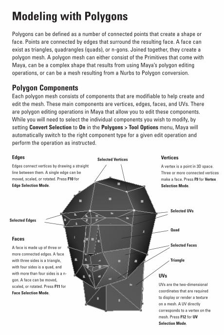
Modeling with PolygonsPolygons can be defined as a number of connected points that create a shape orface. Points are connected by edges that surround the resulting face. A face canexist as triangles, quadrangles (quads), or n-gons. Joined together, they create apolygon mesh. A polygon mesh can either consist of the Primitives that come withMaya, can be a complex shape that results from using Maya’s polygon editingoperations, or can be a mesh resulting from a Nurbs to Polygon conversion.
Polygon ComponentsEach polygon mesh consists of components that are modifiable to help create andedit the mesh. These main components are vertices, edges, faces, and UVs. Thereare polygon editing operations in Maya that allow you to edit these components.While you will need to select the individual components you wish to modify, bysetting Convert Selection to On in the Polygons > Tool Options menu, Maya willautomatically switch to the right component type for a given edit operation andperform the operation as instructed.
Edges
Edges connect vertices by drawing a straightline between them. A single edge can bemoved, scaled, or rotated. Press F10 forEdge Selection Mode.
Selected Edges
Selected Vertices
Selected UVs
Selected Faces
Quad
Triangle
Vertices
A vertex is a point in 3D space.Three or more connected verticesmake a face. Press F9 for Vertex
Selection Mode.
Faces
A face is made up of three ormore connected edges. A facewith three sides is a triangle,with four sides is a quad, andwith more than four sides is a n-gon. A face can be moved,scaled, or rotated. Press F11 forFace Selection Mode.
UVs
UVs are the two-dimensionalcoordinates that are requiredto display or render a textureon a mesh. A UV directlycorresponds to a vertex on themesh. Press F12 for UV
Selection Mode.
booklet_new 11/7/02 2:39 PM Page 12

Vertices
A vertex is a point in 3D space.Three or more connected verticesmake a face. Press F9 for Vertex
Selection Mode.
Extruding Faces
You can further refine your shape by extrudingthe face of a polygon. This extrusion operationinserts faces at the edges of the face to beextruded and allows the selected face or facesto be moved, scaled, or rotated from their originalposition. If you are extruding multiple faces andwant them to maintain a cohesive shape, setPolygons > Tool Options > Keep Faces Together
to On. This only inserts faces at the edges on theborder of the selected faces. Otherwise, faceswill be inserted at every edge. This tool can befound under Edit Polygons > Extrude Face.
Face four is selected.This is the face that willbe extruded.
After the extrude is completeyour faces are added at theedges of the extruded face.
Splitting Polygons
The Split Polygon Tool allows you to divide apolygonal face. You can also use the Tool toinsert vertices on an edge. To assist you, theTool has options that allow you to set how manySnapping Magnets you want and the Snapping
Tolerance for the magnets. By setting Snapping
Magnets to 3, the edge being split will havethree equally spaced division points. Increasingthe Snapping Tolerance increases the influenceof the magnets. With a Snapping Tolerance of 0,the vertex can be added anywhere on the edge.A Tolerance of 100 will force the vertex to snapdirectly to the division points.
A common use of the SplitPolygon tool is to divide aface in half. This is done witha tolerance of 100.
However, the face canbe split anyway youwant as long as thelast vertex ends up onan edge.
Polygon Creation
To create a polygon shape, select Polygons > Create
Polygon Tool. After placing a point, use the middlemouse button to alter its position.
1st Click
4th Click
5th Click2nd Click 3rd Click
After the 3rd click, the polygon can be completedby pressing Enter. The dashed line represents thefinal edge.
You can continue to place points until the desiredshape is achieved. Press Enter to finish.
booklet_new 11/7/02 2:39 PM Page 13

Objects and ComponentsYou can transform objects in Maya by selectingobjects and their components. Selection masksallow you the flexibility to select only the items youwant in a scene. These masks are grouped into threecategories: Hierarchy, Object type, and Componenttype selections. Use the F8 key to quickly togglebetween Object and Component mode.
Selection MasksSelection masks allow you to select the specific items you want to work on. There arethree main groups of selection masks: Hierarchy, Object, and Component. Hierarchymode allows you to select nodes at different levels. In this mode you can select theRoot, Leaf, and Template nodes. Object mode allows you to select scene elements atthe Transform node level. These include objects such as surfaces, curves, and joints.Component-type selections are selections made to objects at the Shape node level,such as isoparms and CVs.
Hierarchy Object Component
hierarchy
Selecting by Hierarchy allows you to select objects at either the Root, Leaf or Template node level. Unlike Object andComponent selection masks, you are not able to turn on more than one mask at a time.
Object
Object selection masks allow you to make selections based on the object types you specify. Left-clicking onthe arrow to the left of the pick masks displays a menu allowing you to turn all objects on or off.
Component
Component selection masks offer a variety of pick masks to choose from. Right-clicking on a mask displays moreselection options.
booklet_new 11/7/02 2:39 PM Page 14

Object TypesScene objects are items such as Cameras, Curves,Surfaces, Dynamics, Joints, Handles, and Deformers.Objects created in Maya are made up of two parts: aTransform node and a Shape node. The Transformnode contains information about an object’s positionand orientation in space. The Shape node defineswhat the object looks like.
Component TypesIn order to change the shape of an object in Maya, you need to modify component-type information. There are a variety of component types such as points,isoparms,faces, hulls, pivot points and handles. These components can be used to interactivelymodify and reshape the appearance of an object.
Surfaces
Selecting by Surfaces allows you toselect the surface geometry of anobject.
SkeletonJoints
Skeleton joints are used to helpcontrol characters.
Deformations
Deformers such as cluster flexorsand lattices modify the shape ofan object.
Curves
Turning off the Curve selectionmeans you can not select thecurves in the scene.
Dynamics
Dynamic objects such as particlescan be separately selected bytoggling the Dynamics button on.
Rendering
Scene objects such as lights,cameras, and textures arerendering object types.
Handles
IK handles are applied to jointchains for animation control.
Hulls
Hulls are guides thatconnect CVs. They can be used toselect and transform rows of CVsat once.
Param Points
Param points are points that liedirectly on a curve or surface.
Pivot Points
Pivot points determinethe location around whichtransformations occur.
Lines
Lines such as isoparms and trim edgesdefine the shape of an object.
Faces
Faces are patchescreated by intersectinglines.
Points
Points such as CVs and polygonalvertices are used to modify theshape of an object.
booklet_new 11/7/02 2:39 PM Page 15

Dependency GraphEverything in Maya is represented by a node with attributes that can be connected toother node attributes. This node-based architecture allows connections to be madebetween virtually everything in Maya. Node attributes determine such things as theshape, position, construction history and shading of an object. With this architecture,you can create inter-object dependencies, shading group dependencies, and makeyour own node connections.
Nodes with Attributes that are connectedThe Dependency Graph is a collection of nodes which are connected together. These connections allow information to move from one node to another and can be viewed in a diagrammatic fashionthrough the Hypergraph and Hypershade windows.
Animation Curve
When an animation is produced in Maya, nodedependencies are created between the animation curvesand the object being animated.
Node DependenciesIn the diagram below you can see the nodes that are dependent on each other tomake up a chess piece. Each node plays a part in creating the final renderedobject. Here you see that the Material node is dependent on the Shape node torender the material, the Shape node is dependent on the revolve node for thechess piece surface, and the Revolve node is dependent on the Curve node tomake the revolve.
Right Mouse Button
Clicking the right mouse buttonover a selected object will giveyou access to an object’s inputand output connections.
booklet_new 11/7/02 2:39 PM Page 16

Attribute Editor
In the Attribute Editor,you can adust theattributes on the inputand output connectionsof a selected node.
Channel Box
In the Channel Box,you can edit anykeyable attributes onthe selected node.
Hypergraph
In the Hypergraph window,you can see the input andoutput connections of aselected node.
Viewing DependenciesDependencies are relationships created between nodes that are connected. Thereare many ways to view and edit dependencies in Maya including the Hypergraph,Attribute Editor, and Channel Box.
By selecting a node and clicking the Input and Output Connections button in theHypergraph window, you can view node dependencies on a selected node. Thiswindow visually displays the connection between nodes with arrows showing thedirection of their dependency to one another.
The Attribute Editor is made up of several tabs allowing you to view relatednodes of a dependency group. In the Attribute editor, you can edit the attributes thataffect these nodes.
In the Channel Box, the selected node is shown with a listing of any keyableattributes that belong to it. Depending on the node selected, it will also show input,output, or shape nodes. If you select more than one node with the same keyableattributes, you can modify them at the same time using the channel box.
booklet_new 11/7/02 2:39 PM Page 17

Setting Keys for AnimationFor an object to be animated, it must change over time. For example, a car mightmove forward or a light might blink on and off. To animate these changes in Maya,you need to set keys for the car’s Translate X attribute or for the light’s intensity. Keysare used to mark attribute values at specific times. Then, animation curves are usedto determine the value in- between the keys.
As a 3D artist, setting keys is one of your most important techniques. Thisanimation technique can be easily applied to your objects and the results can beeasily edited. Once you are familiar with this technique, you will soon find that youspend less time setting keys and more time editing the motion.
Keying AttributesWhen you set keys, you key values for one or more of an object’s attributes atspecific frames in time. These keyframes set the values, while tangents set at eachkey determine the interpolation in between the keys. This interpolation results in ananimation curve that can be edited in the Graph Editor. This editing feature helps youcontrol the quality of your motion.
Step 1: keyframes
Keys are set for at least two points intime. You can set keys for one or moreattributes at the same time. The keysare then stored as animation curves.
Step 2: Animation Curve Shape
In the Graph Editor, you can view andedit the animation curves. At each key,there are tangents set that define theshape of the curve.
Step 3: Playback
When you play back an animation, theobject uses the keys and the valuesdefined by the animation curve to createthe resulting motion.
booklet_new 11/7/02 2:39 PM Page 18
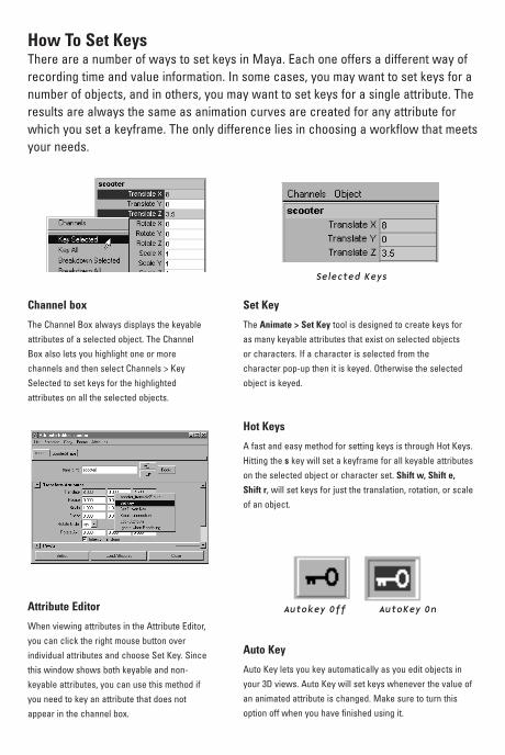
How To Set KeysThere are a number of ways to set keys in Maya. Each one offers a different way ofrecording time and value information. In some cases, you may want to set keys for anumber of objects, and in others, you may want to set keys for a single attribute. Theresults are always the same as animation curves are created for any attribute forwhich you set a keyframe. The only difference lies in choosing a workflow that meetsyour needs.
Channel box
The Channel Box always displays the keyableattributes of a selected object. The ChannelBox also lets you highlight one or morechannels and then select Channels > KeySelected to set keys for the highlightedattributes on all the selected objects.
Attribute Editor
When viewing attributes in the Attribute Editor,you can click the right mouse button overindividual attributes and choose Set Key. Sincethis window shows both keyable and non-keyable attributes, you can use this method ifyou need to key an attribute that does notappear in the channel box.
Auto Key
Auto Key lets you key automatically as you edit objects inyour 3D views. Auto Key will set keys whenever the value ofan animated attribute is changed. Make sure to turn thisoption off when you have finished using it.
Set Key
The Animate > Set Key tool is designed to create keys foras many keyable attributes that exist on selected objectsor characters. If a character is selected from thecharacter pop-up then it is keyed. Otherwise the selectedobject is keyed.
Selected Keys
Autokey Off AutoKey On
Hot Keys
A fast and easy method for setting keys is through Hot Keys.Hitting the s key will set a keyframe for all keyable attributeson the selected object or character set. Shift w, Shift e,
Shift r, will set keys for just the translation, rotation, or scaleof an object.
booklet_new 11/7/02 2:39 PM Page 19

Assigning Materials and Textures
Hypershade
Use the Hypershade windowto create and assign materialsand textures to your objects.
Create Pulldown Menu
Use this menu to change theCreate list to:
• Materials• Textures• Utilities• Lights
Attribute Editor
Use the Attribute Editor to modify theproperties of any node includingmaterial attributes. Select a nodeand press Ctrl-a for quick access tothe Attribute Editor.
Click-drag with MMB thematerial node onto the objectin the workspace to assign it
While geometry defines the shape of a model, shading defines how the model’ssurfaces react to light and details such as color, transparency, and texture.Maya uses Shading group nodes to tell the renderer which materials, textures,and lights will affect the final look of a surface. Shading networks are made upof nodes that define the final look of a rendered surface. Learning the properrole of each of these nodes will ensure that you build shading networks thatrender successfully. Use the Hypershade to make these shading Networks. Itcan be found in Window > Rendering Editors > Hypershade...
booklet_new 11/7/02 2:39 PM Page 20
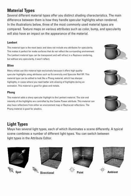
Material Types
Blinn
Many artists use this material type exclusively because it offers high-qualityspecular highlights using attributes such as Eccentricity and Specular Roll Off. Thismaterial type can be edited to look like a Phong material, which has sharperhighlights, in cases where you need better anti-aliasing of highlights during ananimation. This material is good for glass and metals.
Phong
This material adds a sharp specular highlight to the Lambert material. The size andintensity of the highlights are controlled by the Cosine Power attribute. This material canalso have reflections from either an environment map or Raytraced reflections. ThePhong material is good for plastics.
Lambert
This material type is the most basic and does not include any attributes for specularity.This makes it perfect for matte surfaces that do not reflect the surrounding environment.The Lambert material type can be transparent and will refract in a Raytrace rendering,but without any specularity, it won’t reflect.
Several different material types offer you distinct shading characteristics. The maindifference between them is how they handle specular highlights when rendered.In the illustrations below, three of the most commonly used material types arecompared. Texture maps on various attributes such as color, bump, and specularitywill also have an impact on the appearance of the material.
Point
Light TypesMaya has several light types, each of which illuminates a scene differently. A typicalscene combines a number of different light types. You can switch between light types in the Attribute Editor.
Spot AmbientDirectional
booklet_new 11/7/02 2:39 PM Page 21

Rendering ScenesRendering is where all of the work in setting up models, textures, lights, cameras,and effects comes together into a final sequence of images. In very simple terms,rendering is the creation of pixels that are given different colors in order to form acomplete image. A render involves a large number of complex calculations that maykeep your computer busy for quite a while. The key at this stage in the animationprocess is to find a way of getting the best image quality and the fastest render timesso that you can meet your deadlines.
Render ViewMaya’s Render View window allows youto launch a software render and watchthe results as the file is being rendered. Itcan be used for everything from a quicktest on a low quality render to a finalproduction render. However, because itonly renders the current frame, it is notused to render animation. Whilerendering in the Render View window,Maya itself is the renderer; there is nointermediate file or separate renderingapplication as is the case with otherrenderers. Consequently, Maya does notallow you to make changes to the openscene’s data as it is being rendered.
Render View
By default, images are automatically resized to fit intothe Render View window. This means that you may beseeing your image at a zoom value other than 1.0. Thisscaled image will appear jagged in most cases, makingit look like it has anti-aliasing problems. Press the 1:1
button to view the image at its true size. If you still seejagged edges, adjust the anti-aliasing settings in RenderGlobals.
Render View Button
Render Globals Button
booklet_new 11/7/02 2:39 PM Page 22

are automatically resized to fit intondow. This means that you may beat a zoom value other than 1.0. Thisppear jagged in most cases, makingti-aliasing problems. Press the 1:1
mage at its true size. If you still seest the anti-aliasing settings in Render
Render OutputBased on your post-production requirements, your final rendered image orsequence of images will need to suit the medium you are outputting it to. Theseimage properties,such as size, format, and frame padding, are set from the RenderGlobals Window.
Render Resolution
The Render Resolution refers to thedimensions of a rendered frame inpixels. Maya’s list of presets allowsyou to quickly select a resolutionfrom a list of those commonly usedin the industry.
Image Formats
The Image Formats pop-up list allows you tospecify the format youneed your renderedframes to be in. Maya’sonline documentationhas a detaileddescription of how eachof these formats handlesimage, mask, and depthinformation. The MayaIFF file format is alsodocumented.
Renderable Camera
The pop-up Camera list allows youto choose which camera will beused in the Batch render. It ispossible to render from more thanone camera in a Batch render. ThisRender Globals setting does notaffect which camera isused while rendering inthe Render View windowwithin Maya.
Rendering AnimationAn image file name consists of three components when rendering an animation: filename, frame number extension, and file format extension. (A combination of thesethree components is referred to as the file name syntax.)
The file name is the base name for all images in the animation sequence. Theframe number extension represents the frame in the Time Slider in which the imageis rendered. The file format extension indicates your chosen file format. You can seethese combined as a preview at the top of the Render Globals window.
You need to tell Maya what frames to render when rendering an animation. Aftera Start Frame and an End Frame are specified, Maya renders all the frames inbetween by default. However, if you want to render every 10th frame for testpurposes, you can set the By Frame attribute to 10. In this case, Maya only rendersevery 10th frame, beginning with the Start Frame number.
booklet_new 11/7/02 2:39 PM Page 23
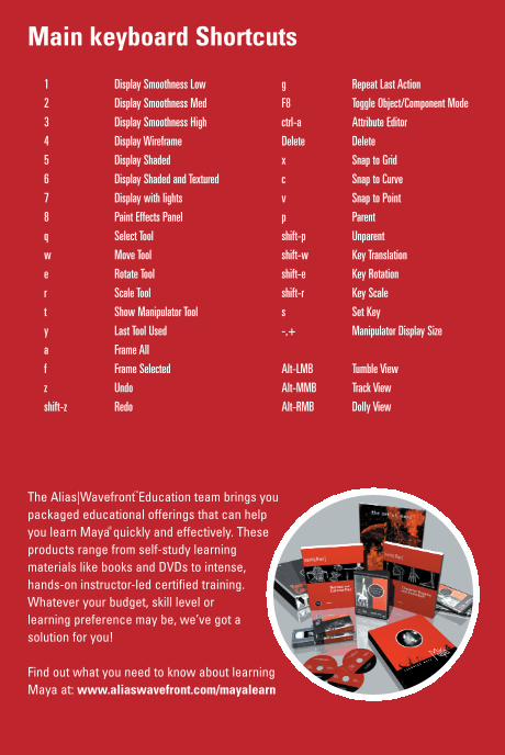
1 Display Smoothness Low
2 Display Smoothness Med
3 Display Smoothness High
4 Display Wireframe
5 Display Shaded
6 Display Shaded and Textured
7 Display with lights
8 Paint Effects Panel
q Select Tool
w Move Tool
e Rotate Tool
r Scale Tool
t Show Manipulator Tool
y Last Tool Used
a Frame All
f Frame Selected
z Undo
shift-z Redo
g Repeat Last Action
F8 Toggle Object/Component Mode
ctrl-a Attribute Editor
Delete Delete
x Snap to Grid
c Snap to Curve
v Snap to Point
p Parent
shift-p Unparent
shift-w Key Translation
shift-e Key Rotation
shift-r Key Scale
s Set Key
-,+ Manipulator Display Size
Alt-LMB Tumble View
Alt-MMB Track View
Alt-RMB Dolly View
Main keyboard Shortcuts
The Alias|Wavefront Education team brings youpackaged educational offerings that can helpyou learn Maya quickly and effectively. Theseproducts range from self-study learningmaterials like books and DVDs to intense,hands-on instructor-led certified training.Whatever your budget, skill level orlearning preference may be, we’ve got asolution for you!
Find out what you need to know about learningMaya at: www.aliaswavefront.com/mayalearn
booklet_new 11/7/02 2:39 PM Page 24
R