Bondek & Powerdek
12
Copyright © by BlueScope Steel Limited. All rights reserved. No part of this artwork shall be reproduced, stored in a retrieval system, or transmitted in any form or by any means, electronic, mechanical, recording or otherwise, without written permission of BlueScope Steel Limited. LYSAGHT ® and COLORBOND ® are registered trademarks of BlueScope Steel Limited ABN 16 000 011 058. BlueScope is a trademark of BlueScope Steel Limited. LYSAGHT ® Structural Decking Systems LYSAGHT ® THERE I S NO EQUIVALENT *Warranty terms and conditions apply. 09 2011 BLUESCOPE LYSAGHT (SABAH) SDN BHD LORONG KURMA OFF JALAN KOLOMBONG 88450 KOTA KINABALU P.O. BOX 12152, 88823 KOTA KINABALU SABAH, MALAYSIA TEL: 6088-445 161 FAX: 6088-421 178 BLUESCOPE LYSAGHT (SARAWAK) SDN BHD LOT 610, SECTION 66, PENDING INDUSTRIAL AREA JALAN MERBAU, 93450 KUCHING SARAWAK, MALAYSIA TEL: 6082-333 621 FAX: 6082-483 486 BLUESCOPE LYSAGHT (B) PTE LTD INDUSTRIAL COMPLEX BERIBI PHASE 1 6KM, JALAN GADONG BANDAR SERI BEGAWAN BE 1118 BRUNEI DARUSSALAM TEL: 673-244 7155 FAX: 673-244 7154 www.bluescopelysaght.com.bn mysupport@bluescopesteel.com BLUESCOPE LYSAGHT (SINGAPORE) PTE LTD 18 BENOI SECTOR, JURONG TOWN, SINGAPORE 629851 TEL: 65-6264 1577 FAX: 65-6265 0951 www.bluescopelysaght.com.sg BLUESCOPE LYSAGHT (MALAYSIA) SDN BHD NO 6, PERSIARAN KEMAJUAN, SEKSYEN 16, 40800 SHAH ALAM SELANGOR DARUL EHSAN, MALAYSIA TEL: 603-5519 2000 FAX: 603-5510 5428 HOTLINE: 1700-81-8688 PENANG 1-2-9, KRYSTAL POINT CORPORATE PARK JALAN TUN DR. AWANG, LEBUH BUKIT KECIL 6 11900 SUNGAI NIBONG, PENANG, MALAYSIA TEL: 604-646 9553 / 6653 FAX: 604-646 6855 JOHOR BAHRU 39, JALAN MOLEK 2/4, TAMAN MOLEK 81100 JOHOR BAHRU, JOHOR, MALAYSIA TEL: 607-351 2660 / 4660 FAX: 607-351 5660 KUANTAN B-288 GROUND FLOOR, JALAN DATO’ LIM HOE LEK 25200 KUANTAN, PAHANG, MALAYSIA TEL: 609-515 7836 / 7837 FAX: 609-515 7834 KOTA BHARU GROUND FLOOR, LOT 312C JALAN KUBUR MARAS OFF JALAN SULTAN YAHYA PETRA 15200 KOTA BHARU, KELANTAN, MALAYSIA TEL: 609-747 5222 / 6222 FAX: 609-747 4212 www.lysaght.com.my Contact your nearest distributor or visit our showroom
description
Bodek and Powerdeck installation manual
Transcript of Bondek & Powerdek

Copyright © by BlueScope Steel Limited. All rights reserved. No part of this artwork shall be reproduced, stored in a retrieval system, or transmitted in any form or by any means, electronic, mechanical, recording or otherwise, without written permission of BlueScope Steel Limited. LYSAGHT® and COLORBOND® are registered trademarks of BlueScope Steel Limited ABN 16 000 011 058. BlueScope is a trademark of BlueScope Steel Limited.
LYSAGHT® Structural Decking Systems
LYSAGHT®
THERE IS NO EQUIVALENT
*Warranty terms and conditions apply.09 2011
BLUESCOPE LYSAGHT (SABAH) SDN BHDLORONG KURMA OFF JALAN KOLOMBONG88450 KOTA KINABALUP.O. BOX 12152, 88823 KOTA KINABALU SABAH, MALAYSIATEL: 6088-445 161 FAX: 6088-421 178
BLUESCOPE LYSAGHT (SARAWAK) SDN BHDLOT 610, SECTION 66, PENDING INDUSTRIAL AREAJALAN MERBAU, 93450 KUCHINGSARAWAK, MALAYSIATEL: 6082-333 621 FAX: 6082-483 486
BLUESCOPE LYSAGHT (B) PTE LTDINDUSTRIAL COMPLEXBERIBI PHASE 16KM, JALAN GADONGBANDAR SERI BEGAWAN BE 1118BRUNEI DARUSSALAMTEL: 673-244 7155 FAX: 673-244 7154
www.bluescopelysaght.com.bn
BLUESCOPE LYSAGHT (SINGAPORE) PTE LTD18 BENOI SECTOR, JURONG TOWN, SINGAPORE 629851TEL: 65-6264 1577 FAX: 65-6265 0951
www.bluescopelysaght.com.sg
BLUESCOPE LYSAGHT (MALAYSIA) SDN BHDNO 6, PERSIARAN KEMAJUAN, SEKSYEN 16, 40800 SHAH ALAMSELANGOR DARUL EHSAN, MALAYSIATEL: 603-5519 2000 FAX: 603-5510 5428HOTLINE: 1700-81-8688
PENANG1-2-9, KRYSTAL POINT CORPORATE PARKJALAN TUN DR. AWANG, LEBUH BUKIT KECIL 611900 SUNGAI NIBONG, PENANG, MALAYSIATEL: 604-646 9553 / 6653 FAX: 604-646 6855
JOHOR BAHRU39, JALAN MOLEK 2/4, TAMAN MOLEK81100 JOHOR BAHRU, JOHOR, MALAYSIATEL: 607-351 2660 / 4660 FAX: 607-351 5660
KUANTANB-288 GROUND FLOOR, JALAN DATO’ LIM HOE LEK25200 KUANTAN, PAHANG, MALAYSIATEL: 609-515 7836 / 7837 FAX: 609-515 7834
KOTA BHARUGROUND FLOOR, LOT 312CJALAN KUBUR MARASOFF JALAN SULTAN YAHYA PETRA15200 KOTA BHARU, KELANTAN, MALAYSIATEL: 609-747 5222 / 6222 FAX: 609-747 4212
www.lysaght.com.my
Contact your nearest distributor or visit our showroom

Features and Benefits
* Please contact BlueScope Lysaght Singapore Sales Consultant (Structural Decking) for more information.
Welcome to LYSAGHT® Structural Steel Decking Formwork and Installation
Guide. We have simplified the work of engineers with this single book which
replaces the two earlier publications - LYSAGHT® BONDEK® II Design and
Construction Guide and LYSAGHT® POWERDEK® Design and Construction
Guide. In addition, this guide book has been developed in accordance to the
latest versions of relevant British Standards and includes advanced design
of formwork and design for fire.
Extensive series of tests have been performed on LYSAGHT® structural steel
decking systems, namely LYSAGHT® BONDEK® II and LYSAGHT® POWERDEK®
steel decking profile, at Bluescope Lysaght Technology facility at Chester
Hill, Sydney, Australia. This is to thoroughly investigate its structural behavior
as formwork as well as longitudinal reinforcement in one-way composite
slabs. LYSAGHT® BONDEK® II decking slabs and LYSAGHT® POWERDEK®
slabs are fire-rated based on fire resistance tests performed at Victoria
University of Technology. LYSAGHT® structural steel floor systems are also
fire-rated certified by PSB Singapore with a Certificate of Conformity for fire
resistance*.
LYSAGHT®
STRUCTURAL STEEL DECKING SOLUTIONS
1 © September 2011 BlueScope Lysaght
INTRODUCTION 1
LYSAGHT® POWERDEK® Structural Steel Decking System 5
COMPOSITE SLAB DESIGN STAGE 9
LYSAGHT® BONDEK® II Structural Steel Decking System 2
FORMWORK DESIGN STAGE 8
CONSTRUCTION AND INSTALLATION 11
Contents
- TO STEEL FRAMING 13
- TO BRICK SUPPORTS 14
REFERENCES
Baiyoke Tower II, Thailand
Emirates Towers, UAE
National Library, Singapore
Marina Bay Sands Singapore
Features Benefits Value to the Developer
Prop-free formwork Minimise input on Shorter period of construction project critical path.
Thinner slab Reduce load on existing columns Cost savings in construction and foundation.
*PSB certified Assurance for QP on the Building Safety Compliance.Fire-rated floor slab product performance

2 © September 2011 BlueScope Lysaght
LYSAGHT® BONDEK® II Structural Steel Decking SystemTypical Unpropped span 2.6m - 3.8m
Section Properties
DESIGN EFFICIENCYThe range of LYSAGHT® BONDEK® II steel decking profile gauges available (0.75mm, 1.0mm and 1.2mm) allows much closer matching of design requirements and deck performance. However, BlueScope Lysaght Singapore is able to offer non-standard thickness other than those stated above, subject to availability.
MATERIAL SPECIFICATIONLYSAGHT® BONDEK® II steel decking profile is roll-formed from hot
dipped, zinc-coated, high tensile steel from BlueScope Steel in base metal thickness (BMT) of 1.2, 1.0 and 0.75mm. The steel conforms to both AS 1397 and BS EN 10147.
Standard coating provided is Z275 (275g/m2 minimum coating mass) or equivalent K18 (performance based). Special coating other than Z275 can also be requested for specific projects. Please contact BlueScope Lysaght Singapore Sales Consultant (Structural Decking) for more information on this.
3 © September 2011 BlueScope Lysaght
FORMWORK
SPANNING CAPACITIESNew design rules have been developed for the design of LYSAGHT® BONDEK® II steel decking profile acting as a structural formwork for the construction of composite and non-composite slabs (where LYSAGHT® BONDEK® II steel decking profile is used as lost formwork). The rules for calculating moment capacities are based on testing performed at BlueScope Lysaght Technology facility at Chester Hill, Sydney, Australia.
The data obtained allowed us to include moment capacities in negative regions of the design model in accordance to BS 5950: Part 4: 1994 and reference document in this Standard: Technical Note 116: Design of profiled sheeting as permanent formwork. As a result, the span limits that previously applied to LYSAGHT® BONDEK® II decking profile in continuous spans have been increased by up to 12%.
COMPOSITE ACTIONLYSAGHT® BONDEK® II steel decking profile has a very high shear-bond capacity. Due to this, LYSAGHT® BONDEK® II profile slabs do not normally have limitations on imposed loads on typical spans unlike trapezoidal profiles.
ECONOMICAL DESIGN FOR FIREFire tests conducted at Victoria University of Technology, Australia, showed that LYSAGHT® BONDEK® II steel decking profile has some
capacity in fire up to 120 minutes. Effective area of LYSAGHT® BONDEK® II profile is mainly concentrated in top flanges of the profile. Lap joints fully casted in concrete contribute more than dovetail ribs. Fire tests have been conducted to investigate temperatures within concrete body and within LYSAGHT® BONDEK® II profile sheeting itself as well as effect of elevated temperatures on shear bond capacity.
QUICKER AND TROUBLE-FREE INSTALLATIONThe installation of LYSAGHT® BONDEK® II structural steel decking systems follow simple, familiar and widely accepted practice. LYSAGHT®BONDEK® II steel decking profile is available in long lengths, so large areas can be quickly and easily covered to form a safe working platform during construction. The bold embossments along the top of the ribs of LYSAGHT® BONDEK® II steel decking profile enhances safety by reducing the likelihood of workers slipping.
TECHNICAL SUPPORTPlease contact BlueScope Lysaght Singapore if you require technical support services. Bluescope Lysaght Sales Consultants (Structural Decking) can also be reached to provide comprehensive design advice and information pertaining to the correct applications of LYSAGHT®
BONDEK® II structural steel decking systems for engineers, architects and builders.
LYSAGHT® BONDEK® II STRUCTURAL STEEL PROFILE
Thickness Grade Section Modulus Cross-sectional Second Moment Weight Area of AreaBMT (mm) mPa Zx 103 mm3/m Ash mm2/mm Ix 104 mm4/m (kg/m2)
1.20* 500 20.03 2014 76.90 16.2
1.00 550 16.69 1678 64.08 13.6
0.75 550 12.50 1259 47.98 10.3
LYSAGHT® BONDEK® II Structural Steel Decking Profile
Table 1: LYSAGHT® BONDEK® II structural steel profile section properties per metre of width
110 120 130 140 150 175 200 225 250
Formwork Span 0.75 BMT
Slab thickness (mm)
3400 3600 3800 4000 4200 4350 4150 3970 3820
4400 4800 4800 4690 4580 4350 4150 3970 3820
1 prop
Single Span (mm)
Continuous Span (mm)
2300 2240 2180 2130 2080 1980 1890 1810 1740
2530 2460 2400 2340 2290 2170 2070 1980 1910
Single Span (mm)
Continuous Span (mm)
No props
110 120 130 140 150 175 200 225 250
Formwork Span 1.0 BMT
Slab thickness (mm)
3400 3600 3800 4000 4400 4800 5350 5120 4920
4600 5000 5200 5600 5930 5620 5350 5120 4920
1 prop
Single Span (mm)
Continuous Span (mm)
2730 2670 2610 2550 2500 2390 2290 2210 2140
3240 3170 3100 3030 2960 2810 2670 2560 2460
Single Span (mm)
Continuous Span (mm)
No props
110 120 130 140 150 175 200 225 250
Formwork Span 1.2 BMT
Slab thickness (mm)
2890 2830 2750 2700 2640 2520 2420 2330 2250
4000 3900 3810 3750 3660 3500 3360 3250 3100
Single Span (mm)
Continuous Span (mm)
No propsFemale Lop Rib
Flute
54
Embossment
24 44
200 200
32 Male Lop Rib
0.75, 1.00 or 1.20 BMT
13Cover Width : 600
Rib
Pan
*subject to availability

5 © September 2011 BlueScope Lysaght
LYSAGHT® POWERDEK® Structural Steel Decking SystemTypical Unpropped span 3.9m - 6.0m
LYSAGHT® POWERDEK® STRUCTURAL STEEL PROFILE
DESIGN EFFICIENCYThe large range of LYSAGHT® POWERDEK® 100 steel decking profile gauges available (1.5mm, 1.2mm and 1.0mm) and LYSAGHT® POWERDEK® 120 profile (1.5mm and 1.2mm) allows much closer matching of design requirements and deck performance.
MATERIAL SPECIFICATIONLYSAGHT® POWERDEK® 100 structural steel decking profile is roll-formed from hot dipped, zinc-coated, high tensile steel from BlueScope Steel, in base metal thickness (BMT) of 1.5mm, 1.2mm and 1.0 mm. LYSAGHT® POWERDEK® 120 decking profile is roll-formed from hot dipped, Aluminum / Zinc-coated, high tensile steel, in base metal thickness (BMT) of 1.5mm and 1.2mm.
The steel conforms to both AS 1397 and BS EN 10147. The grade of metal for the respective BMT are as follow :• for 1.5 BMT, the grade of metal is G450 (450 MPa minimum yield strength)• for 1.2 BMT, the grade of metal is G500 (500 MPa minimum yield strength)• for 1.0 BMT, the grade of metal is G550 (550 MPa minimum yield strength)
Standard coating provided is Z275 (275g/m2 minimum coating mass) or equivalent K18 (performance based). Special coating other than Z275 can also be requested for specific projects. Please contact BlueScope Lysaght Singapore Sales Consultant (Structural Decking) for more information on this. Punches on sides of embossments prevent formation of air pockets under flanges.
4 © September 2011 BlueScope Lysaght
Section Properties
LYSAGHT® POWERDEK® 100 profile and dimensions LYSAGHT® POWERDEK® 120 profile and dimensions
Base Metal Grade Area Self Weight Effective Second Effective Section Thickness (mm) mPa (mm2) (kg/m2) Moment of Area Modulus (lx,mm4/m) (Zx,mm3/m)
1.0 550 2287 19.03 2115960 36390
1.2 500 2715 22.62 2926700 51425
1.5 450 3430 28.00 4218550 76100
LYSAGHT® POWERDEK® 100
Table 2: LYSAGHT® POWERDEK® structural steel profile section properties per metre of width
1.2 500 2905 24.2 4467750 70600
1.5 450 3630 29.6 6310920 98500LYSAGHT® POWERDEK® 120
Notes:Effective second moment of area varies depending on spans. Values in the table are given for maximum spans.
Republic Plaza, Singapore
Parkview Square, Singapore
Petronas Twin Towers, Malaysia Cheung Kong Center, Hong Kong

6 © September 2011 BlueScope Lysaght 7 © September 2011 BlueScope Lysaght
COMPOSITE ACTION
LYSAGHT® POWERDEK® structural steel decking profile has the highest shear-bond capacity among all known steel decking profiles. This allows withstanding very high imposed loads of up to 30kPa and more without additional conventional reinforcement.
ECONOMICAL DESIGN FOR FIRELYSAGHT® POWERDEK® structural steel decking profile has the best fire efficiency among all known structural decks. After 90 minutes of the standard fire test, LYSAGHT® POWERDEK® 100 profile in 1.5mm BMT has 1200mm2 equivalent of fully effective steel per meter width. As a result, composite slabs with LYSAGHT® POWERDEK® profile will not require any additional fire reinforcement in most design cases.
QUICKER AND TROUBLE-FREE INSTALLATIONLYSAGHT® POWERDEK® structural steel decking profile requires minimal fixing of ribs during installation. Since no twist, rotation or sliding is necessary to lock sheets together, handling of the decking sheet is very simple.
TECHNICAL SUPPORTPlease contact BlueScope Lysaght Singapore to if you require technical support services. Bluescope Lysaght Sales Consultants (Structural Decking) can also be reached to provide comprehensive design advice and information pertaining to the correct applications of LYSAGHT® POWERDEK® structural steel decking systems for engineers, architects and builders.
No props
150 175 200 250
Single Span 1.0mm 3550 3380 3250 3010
Double Span 3700 3520 3380 3130
Single Span 1.2mm 4200 4010 3850 3590
Double Span 4360 4170 4010 3730
Single Span 1.5mm 4800 4660 4480 4150
Double Span 5280 5050 4820 4500
Single Span 1.2mm N.A. N.A. 3530 3280
Double Span N.A. N.A. 3680 3410
Single Span 1.5mm N.A. N.A. 5000 4730
Double Span N.A. N.A. 5470 5100
Slab Thickness (mm)Base Metal Thcikness (BMT)SPAN (mm)
LYSAGHT® POWERDEK® 100
LYSAGHT® POWERDEK® 120
Formwork Span
SPANNING CAPACITIES
Long unpropped spanning capability is one of the major advantages of using LYSAGHT® POWERDEK® steel decking profile. It can span up to 6m with 1.5mm thickness of sheeting.
The superior spanning capacities achieved are due to several factors, which include:• Unique structurally effective and stable profile.• High tensile 450 to 550 MPa yield stress steel.
FORMWORK
POWERDEK® 100
0
1
2
3
4
5
6
0
40
Maximum Formwork Span Maximum Imposed Loads
2.7
5.2
6.0
Span
-Met
res
Impo
sed
Load
s - k
Pa
30
20
10
20
30 30
Typical 54mm re-entrant profile
Fig 3.1 Formwork span and imposed loads for LYSAGHT® POWERDEK® steel decking profile
Table 3: Formwork Span for LYSAGHT® POWERDEK® profile
POWERDEK® 120
National Library, Singapore
ITE College East, Simei Campus, Singapore
One Raffles Quay, Singapore

8 © September 2011 BlueScope Lysaght
Formwork Design Stage• LYSAGHT® BONDEK® II Decking Profile • LYSAGHT® POWERDEK® Decking Profile
9 © September 2011 BlueScope Lysaght
Composite Slab Design Stage
Construction Design Sheeting Concrete Imposed Imposed Stage Case Dead Load Gdp Dead Load Construction Storage (see note 1) (see note 2) (see note 3) Gdp Loads Qc Loads Qc
la Strength 1.4 - 1.6 -
lb Strength 1.4 - - 1.6
lla Strength 1.4 1.4 1.6 -
llb Deflection 1.0 1.0 - -
Table 4 - Factored load combinations for strength and deflection calculations
LYSAGHT® structural steel decking systems are designed to work as a formwork during construction stage. The formwork shall be designed in accordance to BS 5950: Part 4:1994 and BS 5950: Part 6:1996, Technical Note 116: Design of profile sheeting as permanent formwork. AS/NZS 4600:1996 may be used when British Standards are not sufficient. The formwork spanning capacities tables in this manual can be used to detail LYSAGHT® structural steel decking systems acting as a structural formwork, provided that the following conditions are satisfied :
1. The support lines extend across the full width of the sheeting and have a minimum bearing of 50mm at the ends of the sheets when resting on steel or concrete and 70mm when resting on other materials such as brick, block or mansory wall.2. The sheets continue within each slab span length without any overlaps or intermediate splicing or jointing longitudinally.3. The sheets are designed as single or continuous span formwork.4. The slab has a uniform cross section.
5. The formwork is not used as a restraint to supporting steel beams during construction. When necessary, restraint capacities can be analysed following first principles.6. Separate consideration is given to sides of the sheeting where edges shall be restrained.7. Profiled steel sheeting ends shall be securely fixed to the supporting structure.8. The ratio of the longer slab span to the shorter slab span (LI / LS) of any two adjacent spans does not exceed 1.2 (ie. LI / LS < 1.2)9. The supports are effectively rigid such that their vertical deflections during the construction phase can be ignored in design.10. Maximum construction imposed load is 1.5 kPa, or 4.5/Span kPa for slab spans less than 3m. Construction imposed load can be applied on the steel deck formwork or recently formed slabs.11. Maximum imposed storage load on the formwork is 4 kPa. This load shall not be applied on recently formed slabs.12. Imposed construction loads shall not be applied to areas supporting storage loads and vice versa.
LYSAGHT®
Steel DeckingSheet
Fig 4.1 Formwork for LYSAGHT® structural steel decking systems
Outline ofconcrete
50mm minimum
Temporaryprops
Slab span L
End support
Slab span L
Interior support Interior support
Temporaryprops
100mm minimum
Equal sheeting spans L
Notes:1. Construction Stage 1 is defined as being prior to the placement of concrete, and Stage 2 as during the placement of concrete up until the concrete hardens.2. Gdc includes an allowance for concrete ponding and the weight of steel reinforcement.3. Both distributed and line load cases must be considered separately.
Deflection limits/loading parametersBS 5950:Part 4: 1994 recommends that the sheeting deflection should not exceed L/130 (but <30mm) under its own weight plus the weight of wet concrete (including reinforcement) provided ponding is taken into account. In this publication, deflection limits of L/130 is adopted.
LYSAGHT® structural steel decking composite slabs shall be designed in accordance to BS 5950: Part 4: 1994, BS 8110: Part 1: 1997, BS 8110: Part 2: 1985, BS 4449: 1997. AS 3600-2001 may be used where relevant.
The design concept is based on "k" and "m" method. Data about shear-bond capacity have been obtained from full-scale tests and supplementary small-scale slip-block tests.
DESIGN METHODSThere are two ways you can design concrete slabs using LYSAGHT® structural steel decking systems :a) Calculate from first principles using relevant British Standards and data from this manual and available through BlueScope Lysaght Singapore and BlueScope Lysaght Technology Centre at Chester Hill, Sydney, Australia.
b) Run our software. This is also likely to produce a more economical design. Please contact BlueScope Lysaght Singapore Sales Consultant (Structural Decking) for a CD copy of the software or enquire for more information on this.
Our software can be used to design composite slabs with LYSAGHT® structural steel decking systems, provided that the following conditions are satisfied :1. It is a common practice to design continuous slabs as a series of single spans. Minimum nominal reinforcement at intermediate supports shall be specified in this case in accordance to BS5950: Part 4: 1994, Clause 6.8. It shall be noted that nominal reinforcement will not prevent formation of wide cracks over supports - requirements of BS8110: Part 1: 1994, Clause 3.5.8 for crack control will not be satisfied. Increased slab thickness may be required in many instances when continuous slabs are designed as a series of simply supported spans.
Fig 5.1 LYSAGHT® structural steel decking systems Pattern 1 for conventional (standard) reinforcement
Negative reinforcement
Wal
l
Wal
l 0.3Ln 0.3Ln
Concrete slab
0.3Ln
Minimum 50mm
Ln
L (span)Restraint at end support
by mass of wallContinuous interior support
Ln
L (span)Little or no
restraint at end support
Minimum 70mm
Wal
l
Wal
l
Cover
LYSAGHT®
Steel DeckingSheet
Fig 5.2 LYSAGHT® structural steel decking systems Pattern 2 for conventional reinforcement when imposed load exceeds twice the dead load
Wal
l
Wal
l 0.3Ln 0.3Ln Cover
Wal
l
Wal
l
Restraint at end supportby mass of wall
Continuous interior support Little or norestraint at end support
Ln
L (span)
Ln
L (span)
LYSAGHT®
Steel DeckingSheet
Concrete slab
0.3Ln
1/3 of negativereinforcement

11 © September 2011 BlueScope Lysaght
Construction and Installation
10 © September 2011 BlueScope Lysaght
Fig 5.3 Permissible zone for location of longitudinal fire reinforcementon on LYSAGHT® BONDEK® II profile
Fig 5.4 Location of fire reinforcement as mesh laid on LYSAGHT® POWERDEK® ribs
SAFETYLYSAGHT® structural steel decking profiles are available in long lengths, so large areas can be quickly and easily covered to form a safe working platform during construction. One level of formwork gives immediate protection from the weather as well as safety to people working on the floor below. The minimal propping requirements provide a relatively open area to the floor below.
The bold embossments along the top of the ribs of LYSAGHT® structural steel decking profile enhance safety by reducing the likelihood of workers slipping.
It is a common sense, by nature, to work safely, protecting yourself and workmates from accidents on the site. Safety includes the practices you use; as well as personal protection of eyes and skin from sunburn, and hearing from noise. For personal safety, and to protect the surface finish of LYSAGHT® structural steel decking profiles, wear clean dry gloves. Do not slide sheets over rough surfaces or over each other. Always carry tools, do not drag them.
Occupational health and safety laws enforce safe working conditions in most locations. Local laws may require you to have fall protection which includes safety mesh, personal harnesses and perimeter guardrails where they are appropriate. BlueScope Lysaght Singapore has a strict adherence to safety guidelines which is implemented on and off-site. BlueScope Lysaght Singapore Occupational Health and Safety Management System is accredited OHSAS 180001:2007 by Lloyd's Register Quality Assurance. In addition, the company is also conferred a "bizSAFE" status by Singapore's Workplace Safety and Health Advisory Committee (WSHAC) for delivering excellence in WSH Management System (Workplace Safety & Health).
LYSAGHT® structural steel decking systems are capable of withstanding temporary construction loads including the mass of workmen, equipment
and materials as specified in this manual. However, it is a good construction practice to ensure protection from concentrated loads, such as barrows, by use of some means such as planks and/or boards.
INSTALLATIONLYSAGHT® structural steel decking profiles are delivered in strapped bundles. If they are not required for immediate use, do stack sheets or bundles neatly and clear of the ground, on a slight slope to allow drainage of water. If they are left in the open, protect the decking sheets with waterproof covers.
PROPPINGIt is a common practice to specify unpropped LYSAGHT® steel decking formwork, however, depending on the span of a the slab, temporary propping may be needed between the slab supports to prevent excessive deflections or collapse of the formwork.
LYSAGHT® steel decking formwork is normally placed directly on prepared propping. Props must stay in place during the laying of the formwork, the placement of the concrete, and until the concrete has reached the strength of 20 MPa. Propping generally consists of substantial timber or steel bearers supported by vertical props. The bearers must be continuous across the full width of the formwork.
Where the underside of the formwork is featured as a finished ceiling, wide form-ply strips attached to the bearers will minimise marking. The width of the form-ply strips depends upon the slab depth, metal thickness and spans. Form-ply strips of 300 mm width have been used successfully.
Propping must be adequate to support construction loads and the mass of wet concrete. The number of props you need for given spans is shown in tables in this manual.
Cover
Concrete slab
Slab
dep
thBearing of LYSAGHT®
Steel Decking Profile(Not less than 50mmat end of sheets)
LYSAGHT®
Steel Decking Profile
Fig 6.1 Typical layout of LYSAGHT® steel decking sheets during propping
Props where required
Bearing of LYSAGHT®
Steel Decking Profile(Not less than 100mmwhere sheeting is continuous)
Slab span(Interior span)
Props where required
Cover
Slab span(End span)
2. The ratio of longer slab span (LI) to the shorter slab span (LS) of any two adjacent spans does not exceed 1.2, that is (LI / LS) < 1.2.3. The bending moments at the supports are only caused by the action of vertical loads applied to the slab.4. The first interior span shall have the same thickness as the end span.5. The geometry of the steel sheeting profile shall conform to the dimensions and tolerances shown on our production drawings. Sheeting with embossments of a depth less than that specified on these drawings shall not be used as composites unless the values of "k" and "m" are revised.6. The specified concrete strength grade is in the range C30 to C40. The wet concrete density must be 2400kg/m3 for normal weight concrete. The concrete shall follow the recommendations given in BS 8110.7. Composite action must be assumed to exist between the steel sheeting and the concrete once the concrete in the slab has attained a compressive strength of 20 MPa. Prior to the development of composite action during construction, potential damage to the shear connection must be avoided, and maximum construction imposed loads shall be limited to 1.5 kPa. 8. Reinforcement Pattern 2 shall be used when imposed load exceeds twice the dead load.
REINFORCEMENTSteel reinforcement is necessary to control shrinkage and temperature effects, as flexural negative reinforcement over supports and in some instances for fire engineering purposes. It shall comply with requirements of BS 4449:1997 for bars and with BS 4483:1998 for fabric. Reinforcement Grade 460B shall be specified.
SHEAR STUDSShear studs for composite beams may be specified with LYSAGHT® structural steel decking profiles concrete slabs as required by BS 5950:Part 3: section 3.1 where relevant. However, for LYSAGHT® POWERDEK® decking profile, strength reduction factors are not
applicable since it forms a solid slab. Shear studs shall not be considered when composite beams are not a design option, such as concrete frame buildings or composite slabs supported by masonry walls.
DESIGN FOR FIRELYSAGHT® structural steel decking profiles composite slabs shall be designed for fire conditions in accordance to BS 5950-8: 1990, BS 476-20: 1987 and BS 476-21: 1987.
Reduction factors are applied to allow for the adverse effect of elevated temperatures on the mechanical properties of concrete and steel. Values of these reduction factors have been derived from fire tests conducted at Victoria University of Technology, Australia and extensive finite element analysis of the composite slabs.
Reduced shear bond capacity is also considered for elevated temperatures. Our software is able to detail LYSAGHT® structural steel decking profiles composite slabs when the soffit is exposed to fire, provided that the following conditions are satisfied:
1. The composite slab acts as a one-way element spanning in the direction of the sheeting ribs for both room temperature and fire conditions.2. The composite slab has been initially designed and detailed for room temperature conditions in accordance to this manual.3. The fire design load is essentially uniformly distributed and static in nature.4. Adequate detailing of slab jointing, edges, slab holes and cavities (for penetrating, embedded or encased services) to provide the appropriate fire resistance period. Alternatively the local provision of suitable protection (such as fire spray material) will be necessary.5. The fire periods are 30, 60, 90, 120, 180 or 240 minutes.6. Refer to figure 5.3 and 5.4 for the placement of fire reinforcement for additional fire resistance in LYSAGHT® BONDEK® II steel decking profile and LYSAGHT® POWERDEK® steel decking profile respectively.
x bx b
20
50yb
Permissible zone for longitudinal fire reinforcement Ast.f +
Concrete
LYSAGHT®
BONDEK II®
Xb > 30mm
Top tensile (negative) reinforcement
Fire reinforcement

13 © September 2011 BlueScope Lysaght12 © September 2011 BlueScope Lysaght
INTERLOCKING THE SHEETS
INSTALLING LYSAGHT® STRUCTURAL® STEEL DECKING PROFILE SHEETS ON STEEL FRAMES
LAYINGLYSAGHT® structural steel decking profiles must be laid with the sheeting ribs aligned in the direction of the designed spans. Other details include the following:1. The slab supports must be prepared for bearing and slip joints as required.2. Lay the steel decking sheets continuously over each slab span without any intermediate splicing or jointing.3. Lay the steel decking sheets end to end. Centralise the joint at the slab supports. Where jointing material is required, the sheets may be butted against the jointing material.4. Support the steel decking sheets across their full width at the slab support lines and at the propping support lines.5. For the supports to carry the wet concrete and construction loads, the minimum bearing is 50mm for ends of steel sheets, and 100mm for intermediate supports over which the sheeting is continuous.6. In exposed applications, treat the end and edges of the steel decking sheets with a suitable edge treatment to prevent entry of moisture.
Method 2Position LYSAGHT® BONDEK® II sheet at an angle. Interlock sheets by lowering sheet in through an arc.
Fig 7.1 Two methods of interlocking adjacent LYSAGHT® BONDEK® II sheets
Method 1Position LYSAGHT® BONDEK® II sheet parallel with previously-laid sheet. Interlock sheets by applying pressure to either position.
SECURING THE PLATFORMOnce laid, LYSAGHT® structural steel decking systems provide a stable working platform. The steel decking sheet shall be fixed to supporting structure at end supports with screws or nails or equivalent. Where additional security is needed, one can use either weights or screws or nails into the propping bearers.
GENERAL FASTENINGLYSAGHT® structural steel decking systems may be installed directly on erected structural steelwork.
The sheeting shall be fixed to the structural steel using spot welds,
or fasteners such as drive nails or self-drilling screws. Place the fixings (fasteners and spot welds) in the flat areas of the pans adjacent to the ribs or between the flutes. The frequency of fixings depends on wind or seismic conditions and good building practice. However, at least one fastener per pan shall be provided at end supports.
One example of fixing system is as follow :• At the end of steel sheets: use a fixing at every rib (Figure 8.1).• At each intermediate slab support over which the sheeting is continuous: use a fixing at the ribs on both edges (Figure 8.2).• Fix LYSAGHT® structural steel decking profiles with drive nails, self- drilling screws or spot welds.• Drive nails should be powder-activated, steel nails 4mm nominal diameter, suitable for structural steel of 4mm thickness or greater.• For structural steel up to 12mm thickness, use 12-24 x 38mm self-
drilling hexagon head screws or equivalent.• For structural steel over 12mm thickness, pre-drill and use 12-24 x 16mm hexagon head screws or equivalent.• Spot welds should be 12mm minimum diameter. Surfaces to be welded must be free of loose material and foreign matter. Where the steel decking soffit or the structural steelwork has a pre-painted surface, securing methods other than welding may be more appropriate. Take suitable safety precautions against fumes during welding zinc coated products.
Fig 6.2 Installation of LYSAGHT® structural steel decking systems
LYSAGHT® BONDEK® II Steel Decking ProfileOverlapping ribs of LYSAGHT® BONDEK® II decking profile sheeting are interlocked. Either one of two methods shown can be used in most situations, though variations may also work.
In the first method, lay adjacent sheets loosely in place. Place the female lap rib overlapping the male lap rib of the previous steel decking
sheet and apply foot pressure, or a light kick, to the female lap rib (Figure 7.1). In the second method, offer a new steel decking sheet at an angle to the one previously laid, and then simply lower it down, through an arc (see Figure 7.1). If the steel sheets do not interlock neatly (perhaps due to some damage or distortion from site handling or construction practices) use screws to pull the laps together tightly. See section on "Fastening Side-lap joints".
Fig 7.2 Fixing LYSAGHT® POWERDEK® steel decking sheets
LYSAGHT® POWERDEK® II Steel Decking Profile
a) Place two sheets and press down 2nd sheet until LYSAGHT® POWERDEK® laps against next sheet to form a rib
b) Place LYSAGHT® rib clip across both halves of rib and press down. Only one clip per rib at midspan is necessary for 1.0 BMT, 1.2 BMT and 1.5 BMT LYSAGHT® POWERDEK® 100; three clips for 1.5 BMT LYSAGHT® POWERDEK® 120 at quarter points required.
The minimum bearing length of LYSAGHT® structural steel decking profile sheets at supports shall be 50mm when resting on steel or concrete, and 70mm when resting on masonry surface, such as brick or block.

15 © September 2011 BlueScope Lysaght
CONSTRUCTION AND MOVEMENT JOINTSJoints used between LYSAGHT® structural steel decking profile slabs generally follow accepted construction practices. Construction joints are included between slabs for the convenience of construction. Movement joints allow relative movement between adjoining slabs. The joints may be transverse to, or parallel with, the span of the steel decking slab. Movement joints need a slip joint under the steel decking sheeting. (Figure 8.3).
The steel decking sheet and any slab reinforcement are not continuous through a joint. Design engineers generally detail the location and spacing of joints because joints affect the design of a slab.
FASTENING SIDE LAP JOINTSIf LYSAGHT® structural steel decking sheets have been distorted in transport, storage or erection, sidelap joints may need fastening to maintain a stable platform during construction, to minimise concrete see page during pouring, and to gain a good visual quality for exposed soffits (Figure 8.4).
CUTTING AND FITTING EDGE FORMEDGE FORM is a simple C-shaped section that simplifies the installation of most LYSAGHT® structural steel decking slabs. It is easily fastened to the steel decking sheet profile, neatly retaining the concrete and providing a smooth top edge for quick and accurate screeding. It is made to suit any slab thickness.
EDGE FORM is easily spliced and bent to form internal and external corners of any angle and must be fitted and fully fastened as the sheets are installed. There are various methods of forming corners and splices. Some of these methods are shown in Figure 8.5. Fasten EDGE FORM to the underside of unsupported LYSAGHT® structural steel decking panels every 200mm. The top flange of EDGE FORM must be tied to the ribs at every 600mm with tie back strap 25mm x 1.0mm (Figure 8.6). Use 10-16 x 16mm self-drilling screws.
14 © September 2011 BlueScope Lysaght
INSTALLING LYSAGHT® STRUCTURAL® STEEL DECKING PROFILE SHEETS ON BRICK SUPPORTS
Brick walls are usually considered to be brittle and liable to crack from
imposed horizontal loads. Thermal expansion and contraction, long-term
shrinkage, creep effects and flexural deflection of concrete slabs may
be sufficient to cause such cracking. To prevent the cracking, LYSAGHT®
structural steel decking profile slabs are not usually installed directly
on brick supports, although this is not always the case in earthquake
construction.
SLIP JOINTS Generally, a slip joint is provided between steel decking sheet and masonry supports (Figure 8.3).
Slip joint material must allow movement to occur, usually by allowing flow under pressure or temperature, however it must not run or solidify. Generally, the materials are a non-rotting, synthetic carrier impregnated with a neutral synthetic or petroleum-based material.
COMPOSITE BEAMSStud welding through the sheet has been considered a suitable securing method for the sheeting in a composite beam. However, some preliminary fixing by one of the methods mentioned in previous section is necessary to secure the sheeting prior to the stud welding. Some relevant welding requirements are:• Mating surfaces of steel beam and sheeting to be cleaned of scale,
rust, moisture, paint overspray, primer, sand, mud or other contamination that would prevent direct contact between the parent material and the steel decking profile;• Welding must be done in dry conditions by a certified welder; • For pre-painted LYSAGHT® steel decking profile sheets, special welding procedures may be necessary• For sheets transverse to beams, stud welding must be between pan flutes to ensure there is no gap between mating surfaces.
Fig 8.1 Fixing at end of sheets. Fig 8.2 Fixing at intermediate slab supports over which the sheeting is continuous.
Fig 8.1 and 8.2 Positions for fixing LYSAGHT® steel decking profile
• At least one fastener per pan (screws, nails, or equivalent) shall be provided at end support.• Slip joint material may be placed directly in contact with the cleaned surface of steelwork.• The top course of masonry should be level, or finished with a levelled bed of mortar to provide an even bearing surface. Lay the top courses
of bricks with the frogs facing down.• The width of a slip joint should not extend beyond the face of the slab support.• The slip joint material must have adequate compressive strength to avoid it being compressed into irregularities of the mating surfaces and thus becoming a rigid joint.
LYSAGHT® Steel Decking Profile
LYSAGHT® Steel Decking Profile
LYSAGHT® Steel Decking Profile and reinforcement are not continuous through the movement joint.
Jointing material
Concrete
Slip joint
Minimum cover25mm
Concrete
Slip joint
Slip joint
Fig 8.3 Typical movement and slip joints
Fig 8.4 Fixing at a side-lap
10-24 x 16mm hex. headself-drilling screw, midwaybetween embossments.
LYSAGHT® Steel Decking Profile. Edge form
Fastening bottom flange of Edge Form
Fastening positions
Fasten Edge Form to the undersideof unsupported LYSAGHT® Steel Decking Profile at 300mm maximum centres.
Fastening top flange of Edge Form
Edge form
Hoop iron LYSAGHT® Steel Decking Profile.
Tie back strap
Edge form
Tie top flange of Edge Form to LYSAGHT® Steel Decking Profile ribs, with hoop iron, every 600mm maximum.
Hoop iron
Edge form
Fig 8.5 Typical fastening of EDGE FORM to LYSAGHT® BONDEK® II and LYSAGHT® POWERDEK® steel decking profile
LYSAGHT® BONDEK® II
LYSAGHT® POWERDEK®

16 © September 2011 BlueScope Lysaght 17 © September 2011 BlueScope Lysaght
SEALINGSeepage of water or fine concrete slurry can be minimised by following common construction practices. Generally, gaps are sealed
with waterproof tape or by sandwiching contraction joint material
between the abutting ends of LYSAGHT® steel decking sheet. If there
is a sizeable gap, the waterproof tape has to be supported.
HOLESLYSAGHT® structural steel decking profiles act as longitudinal tensile reinforcement similarly to conventional bar or fabric reinforcement does in concrete slabs. Consequently, holes in the steel decking sheets, to accommodate pipes and ducts, reduce the effective area of the steel sheeting and can adversely affect the performance of a slab.
Some guidelines for holes are (Figure 8.8 & 8.9): 1. Place holes in the central pan of any sheet, with a minimum edge distance of 15mm from the rib gap.2. Holes should be round, with a maximum diameter of 150mm.3. For slabs designed as a continuous slab, space holes from an interior support of the slab should be no more than one tenth of a clea span.
INSPECTIONWe recommend regular qualified inspection during the installation, to ensure that the steel sheeting is installed in accordance with this manual and good building practice.
CUTTINGIt is easy to cut LYSAGHT® steel decking sheets to fit. Use a power saw fitted with an abrasive disc or metal cutting blade. Initially, lay the sheet with its ribs down, cut through the pans and part-through the ribs, then turn it over and finish by cutting the tops of the ribs.
REINFORCEMENTLYSAGHT® steel decking profile acts as longitudinal tensile reinforcement. The condition of sheeting should be inspected before concrete is poured over. Reinforcement in slabs carries and distributes the design loads and to control cracking. Reinforcement is generally described as transverse and longitudinal in relation to span, but other reinforcement required for trimming may be positioned in other
orientations. Figure 8.11 and 8.12 shows a typical cross-section of a LYSAGHT® BONDEK® II profile and LYSAGHT® POWERDEK® profile composite slab and associated terms. Reinforcement must be properly positioned, lapped where necessary, to ensure continuity and tied to prevent displacement during construction. Fixing of reinforcement shall be in accordance with BS-8110: Part 1.
To ensure the specified minimum concrete cover, the uppermost layer of reinforcement must be positioned and tied to prevent displacement during construction. Where fabric is used in thin slabs, or where fabric is used to act as both longitudinal and transverse reinforcement, pay particular attention to the required minimum concrete cover and the required design reinforcement depth at the splices - splice bars are a prudent addition. Always place chairs and spacers on pan areas. Depending upon the type of chair and its loading, it may be necessary to use plates under chairs to protect the steel decking sheets, particularly where the soffit will be exposed. Transverse reinforcement may be used for spacing or supporting longitudinal reinforcement.
Location of Holes in LYSAGHT® BONDEK® II Steel Decking Profile
Zone for holes through LYSAGHT®
BONDEK® II sheet in central panMax. diameter 150mm
15mm minimum
Location of holes in sheet
Minimum 0.1 Ln
Minimum 0.1 LnZone for holes
in continuous slabs
Interior supportsLn
LYSAGHT®
BONDEK® II
Location of holes relative to supports in continuous slabs
Fig 8.9 Zones for location of holes through LYSAGHT® BONDEK® II steel decking profile
Location of Holes in LYSAGHT® POWERDEK® Steel Decking Profile
Zone for holes through LYSAGHT® POWERDEK® sheet in central pan Max. diameter 150mm
150mm
15mm minimum
Minimum 0.1 Ln
Minimum 0.1 LnZone for holes
in continuous slabs
LYSAGHT®
POWERDEK®
Interior supports
Ln
Fig 8.10 Location of holes relative to supports in continuous slabs of LYSAGHT® POWERDEK® steel decking profile
Fig 8.11 Typical cross-section of LYSAGHT® BONDEK® II profile composite slab showing common terms
LYSAGHT® BONDEK® II
Concrete Deformed bar reinforcement Concrete cover
Reinforcementdepth
Top-facereinforcement
Bottom-facereinforcement
Longitudinal reinforcement(parallel with ribs)
Transverse reinforcement(90˚ to ribs)
Dept
h of
com
posi
te s
lab
External corner
1. Notch top flange for the required angle
2. Cut 'V' in bottom flange
3. Bend corner of Edge Form to the required angle, overlapping bottom flanges.
Internal corner
1. Cut top and bottom flanges square.
2. Bend Edge Form to required angle. 3. Fasten top flange,
each side of corner, to LYSAGHT® Steel Decking Profile rib 100mm from corner.
Splicing two pieces
1. Cut-back top and bottom flanges of one Edge Form section approcimately 200mm.2. Cut slight taper on web.3. Slide inside adjoining Edge Form, and fasten webs with at least 2 screws.
Waterproof tape over gap
Sizeable gap between LYSAGHT® BONDEK® II sheets Where necessary, insert
Bonfill into ribs to support tape
Waterproof tape over end of rib
Fig 8.7 Use waterproof tape to seal joints in LYSAGHT® BONDEK® II sheets
ITEMS EMBEDDED IN SLABSIncluded are pipes and conduits, sleeves, inserts, holding-down bolts, chairs and other supports, plastic strips for plasterboard attachment, contraction joint material and many others. Location of
items within the slab, see Figure 8.8. Minimise the quantity and size of holes through the steel sheeting by hanging services from the underside of steel decking sheet using accessories such as BON-NUT.
Fig 8.6 Fabrication of formwork is easy with EDGE FORM
Top-face reinforcement
Bottom-face reinforcement
Zone for pipes laid across the ribs(between top and bottom reinforcement) Concrete
Zone for pipes and other itemslaid parallel with the ribs
Fig 8.8 Zones for location of items embedded in slabs
LYSAGHT® BONDEK® II
18 © September 2011 BlueScope Lysaght 19 © September 2011 BlueScope Lysaght
TRANSVERSE REINFORCEMENTTransverse reinforcement is placed at right-angles to the ribs of LYSAGHT® steel decking profile sheet. Deformed bar or fabric reinforcement may be used. In most applications, the transverse reinforcement is for the control of cracks caused by shrinkage and temperature effects, and for locating longitudinal reinforcement. To control flexural cracking in the top face of the slab, transverse reinforcement in the top-face may be required over walls or beams which run in the same direction as the LYSAGHT® steel decking profile sheets. For ease of construction, reinforcement for control of cracking due to shrinkage and temperature is usually fabric reinforcement.
LONGITUDINAL REINFORCEMENTLongitudinal reinforcement is positioned to carry design loads in the same direction as the ribs of LYSAGHT® steel decking profile. Deformed bar or fabric reinforcement may be used. Top-face longitudinal reinforcement is usually located over interior supports of the slab and extends into approximately a third of the adjoining spans. Bottom-face longitudinal reinforcement is located between supports of the slab. However, depending upon the detailing over the interior supports, it may be continuous, lapped, or discontinuous. Bottom-face longitudinal reinforcement may be placed on top of or below transverse reinforcement. Location of bottom-face longitudinal reinforcement in elevated temperatures requires special design. (Figure 2.1)
TRIMMERSTrimmers are used to distribute the design loads to the structural portion of the slab and/or to control cracking of the concrete at penetrations, fittings and re-entrant corners. Deformed bar or fabric reinforcement may be used. Trimmers are sometimes laid at angles other than along or across the span, and generally located between the top and bottom layers of transverse and longitudinal reinforcement. Trimmers are generally fixed with ties from the top and bottom layers of reinforcement.
CONCRETE SPECIFICATIONSThe concrete is to have the compressive strength as specified in the project documentation and the materials for the concrete and the concrete manufacture should conform to BS8110: Part 1: 1997, Section 6.
CONCRETE ADDITIVESAdmixtures or concrete materials containing calcium chloride or other chloride salts must not be used. Chemical admixtures including plasticisers may be used if they comply with BS8110.
CONCRETE PREPARATIONBefore concrete is placed, remove any accumulated debris, grease or any other substance to ensure a clean bond with the LYSAGHT® steel decking profile sheet. Remove any accumulated rainwater.
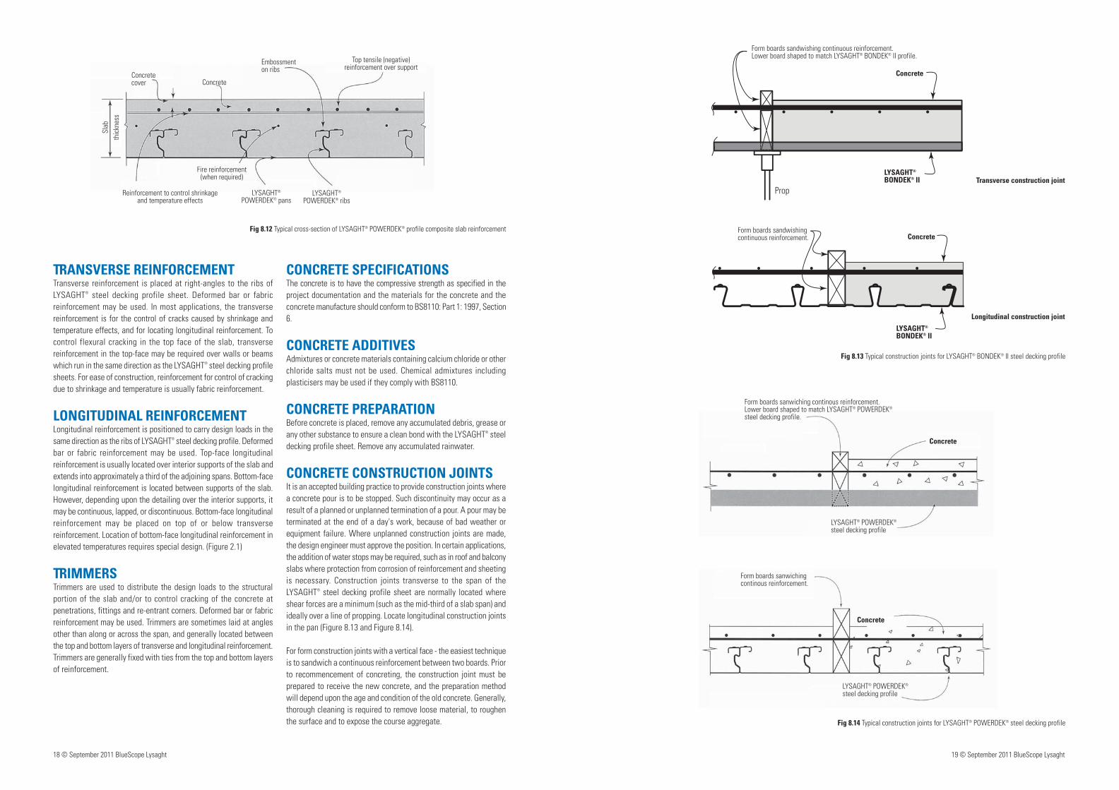
CONCRETE CONSTRUCTION JOINTSIt is an accepted building practice to provide construction joints where a concrete pour is to be stopped. Such discontinuity may occur as a result of a planned or unplanned termination of a pour. A pour may be terminated at the end of a day's work, because of bad weather or equipment failure. Where unplanned construction joints are made, the design engineer must approve the position. In certain applications, the addition of water stops may be required, such as in roof and balcony slabs where protection from corrosion of reinforcement and sheeting is necessary. Construction joints transverse to the span of the LYSAGHT® steel decking profile sheet are normally located where shear forces are a minimum (such as the mid-third of a slab span) and ideally over a line of propping. Locate longitudinal construction joints in the pan (Figure 8.13 and Figure 8.14).
For form construction joints with a vertical face - the easiest technique is to sandwich a continuous reinforcement between two boards. Prior to recommencement of concreting, the construction joint must be prepared to receive the new concrete, and the preparation method will depend upon the age and condition of the old concrete. Generally, thorough cleaning is required to remove loose material, to roughen the surface and to expose the course aggregate. Fig 8.14 Typical construction joints for LYSAGHT® POWERDEK® steel decking profile
Fig 8.13 Typical construction joints for LYSAGHT® BONDEK® II steel decking profile
Fig 8.12 Typical cross-section of LYSAGHT® POWERDEK® profile composite slab reinforcement
Transverse construction joint
Longitudinal construction joint
Form boards sandwishing continuous reinforcement.Lower board shaped to match LYSAGHT® BONDEK® II profile.
Concrete
LYSAGHT® BONDEK® II
Concrete cover Concrete
Embossment on ribs
Top tensile (negative)reinforcement over support
LYSAGHT®
POWERDEK® ribsLYSAGHT®
POWERDEK® pans
Fire reinforcement(when required)
Reinforcement to control shrinkageand temperature effects
Slab
thic
knes
s
Form boards sanwiching continous reinforcement.
Concrete
LYSAGHT® POWERDEK® steel decking profile
Prop
Form boards sandwishing continuous reinforcement. Concrete
LYSAGHT® BONDEK® II
Form boards sanwiching continous reinforcement. Lower board shaped to match LYSAGHT® POWERDEK® steel decking profile.
Concrete
LYSAGHT® POWERDEK® steel decking profile

BS 5950: Part 4: 1994 Structural use steel work in buildings Part 4. Code of practice for design of composite slabs with profiled steel sheeting.
BS 8110: Part 1: 1997 Structural use of concrete Part 1. Code of practice for design and construction.
BS 8110: Part 2: 1985 Structural use of concrete Part 2. Code of practice for special circumstances.
BS 5950: Part 6:1995 Structural use of steelwork in building Part 6. Code of practice for design of light gauge profiled steel sheeting.
BS 5950: Part 9: 1994 Structural used of steel work in building part 9. Code of practice for stressed skin design.
BS 6399: Part 1: 1996 Loading for buildings Part 1. Code of practice for dead and imposed loads.
BS 4483:1998 Steel fabric for the reinforcement of concrete.
BS 4449:1997 Specification for carbon steel bars for the reinforcement of concrete.
BS 5950; Part 8: 1990 structural use of steel work in building Part 8. Code of practice for fire resistant design. BS 5950-5: 1998 Structural use of steelwork in building Part 5. Code of practice
for design of cold formed thin gauge sections.
BS EN 10147:2000 Continuously hot-dip zink coated structural steels strip and sheet - Technical delivery conditions.
BS 6399: Part 3: 1988 Loading for buildings Part 3. Code of practice for imposed roof loads.
BS 476-20: 1987 Fire tests on building materials and structures Part 20: Method for determination of the fire resistance of elements of construction (general principles).
BS 476-21: 1987 Fire tests on building materials and structures Part 21: Methods for determination of the fire resistance of load bearing elements of construction.
BS 5328: Part 4:1990 Concrete Part 4. Specification for the procedures to be used in sampling, testing and assessing compliance of concrete.
BS 1881: Part 116: 1983 testing concrete Part 116. Method for determination of compressive strength of concrete cubes.
BS EN 10 002-1: 1990 Tensile testing of metallic materials Part 1. Method of test at ambient temperature.
AS/NZS 4600:1996 Cold-formed steel structures.
AS 3600-2001 Concrete structures.
REFERENCES
20 © September 2011 BlueScope Lysaght
Fig 8.15 Fixing plaster board to LYSAGHT® POWERDEK® steel decking profile
PLACINGThe requirements for the handling and placing of the concrete are covered in BS8110: Part 1: 1997, Section 6.2.
The concrete is placed between construction joints in a continuous operation so that new concrete is placed against plastic concrete to produce a monolithic mass. If the pouring has to be discontinued for any more than approximately one hour, depending on the temperature, a construction joint may be required. Start pouring close to one end, and spread concrete uniformly, preferably over two or more spans. It is a good practice to avoid excessive heaping of concrete and heavy load concentrations. When concrete is transported by wheel barrows, the use of planks or boards is recommended. During pouring, the concrete should be thoroughly compacted, worked around ribs and reinforcement, and into corners of the EDGE FORMS by using a vibrating compactor. Ensure that the reinforcement remains correctly positioned so that the specified minimum concrete cover is achieved. Unformed concrete surfaces are screeded and finished to achieve the specified surface texture, cover to reinforcement, depths, falls or other surface detailing. Surfaces which will be exposed, such as EDGE FORMS and exposed soffits, should be cleaned of concrete spills while still wet, to reduce subsequent work.
CURINGAfter placement, the concrete is cured by conventional methods, for example, by keeping the slab moist for at least seven days or by covering the surface with sand, building paper or polythene sheeting immediately after it has been moistened with a fine spray of water. Follow good building practice. Be particularly careful when curing in very hot or very cold weather. Until the concrete has cured, it is a good practice to avoid concentrated loads such as barrows and passageways with heavy traffic.
WHEN TO REMOVE PROPSVarious factors affect the earliest time when the props may be removed and a slab initially loaded. Methods of calculating times and other guides are given in AS 3610-1995, Clause 5.4.3
SOFFIT AND EDGE FORM FINISHESFor many applications, LYSAGHT® steel decking profiles give an attractive appearance to the underside (or soffit) of a composite slab, and will provide a satisfactory ceiling, for example, in car parks,
under-house storage and garages, industrial floors, etc. Similarly, EDGE FORM will give a suitable edging. Additional finishes take minimal extra effort. Where the LYSAGHT® BONDEK® II steel decking soffit is to be the ceiling, take care during construction to minimise propping marks (refer to installation - Propping), and to provide a uniform surface at the side-laps (refer to section on Fastening Side-lap joints). Exposed surfaces of LYSAGHT® steel decking profiles soffit and EDGE FORM may need cleaning and/or preparation for any following finishes.
PLASTERINGFinishes such as vermiculite plaster can be applied directly to the underside of LYSAGHT® steel decking profiles with the open rib providing a positive key. With some products, it may be necessary to treat the galvanised steel surface with an appropriate bonding agent prior to application. Plaster-based finishes can be trowelled smooth, or sprayed on to give a textured surface. They can also be coloured / painted to suit interior design requirements.
CHANGE OF FLOOR LOADINGSWhere a building is being refurbished, or there is a change of occupancy and floor use, you may need to increase the fire resistance of the LYSAGHT® steel decking composite slabs. This may be achieved by the addition of a suitable fire protection material to the underside of the slabs. The open ribs of LYSAGHT® steel decking sheet provide a positive key to keep the fire spray in position. Such work is beyond the scope of this guide book.
SUSPENDED CEILINGCeilings are easily suspended from LYSAGHT® steel decking slabs using Ceiling Suspension Nuts and BON-NUT suspension nuts. Threaded rods or wire hangers are then used to support the ceiling. Alternatively, hangers may be attached to eyelet pins powder-driven into the underside of the slab, or to pigtail hangers inserted through pilot holes in the LYSAGHT® steel decking sheet before concreting (Figure 8.16).
SUSPENDED SERVICESServices such as fire sprinkler systems, piping and ducting are easily suspended from LYSAGHT® steel decking profile slabs using BON-NUT suspension nuts. Ceiling Suspension Nuts are suitable for services other than fire sprinkler systems - threaded rods being used to support the services.
LYSAGHT® POWERDEK® steel decking profile
Concrete
Plaster board
Batten
Fixing Plasterboard
Wynn Resort, Macau, SAR
Pit Building, Singapore
Bahrain Financial Harbour, Bahrain