Bolting materials subsea
34
Bolting materials subsea CONFERENCE - Materials in Offshore Constructions, Esbjerg June 2th 2006 Bjarte Lillebø, Det Norske Veritas, Bergen, Norway
Transcript of Bolting materials subsea
Bolting materials subsea
CONFERENCE - Materials in Offshore Constructions, Esbjerg June 2th 2006
Bjarte Lillebø, Det Norske Veritas, Bergen, Norway
Version Slide 206 June 2006
Background
The high integrity bolted connections used in the offshore industry are often critical parts of the plant or piping system. Failure of such connections has been found to be a major cause of gas/oil leakage on offshore installations.
High strength materials for bolting are needed for subsea use by the offshore industry. However, several candidate materials may be susceptible to failure due to hydrogen and associated cracking caused by the cathodic protection system.
Version Slide 306 June 2006
Subsea applications of high integrity bolted joints
Subsea / submerged systems
Wellheads
Xmas tree flanges
Structural connections
Flanges

Version Slide 406 June 2006
Connection type /flange design /pre-loading requirement
Bolting standards
Bolting material properties:- Strength- Corrosion resistance- Galling properties- Susceptible to hydrogen effects
Bolting manufacture (incl. quality control)
Bolting installation methods: - Hydraulic torque (accuracy +/- 25%)- Hand torque (accuracy +/- 30%) - Hydraulic tension (accuracy +/- 10%)
Corrosion protection (CP, coating system)
Maintenance of bolted connections in service
“Bolting Technology” - an interdisciplinary subject
Version Slide 506 June 2006
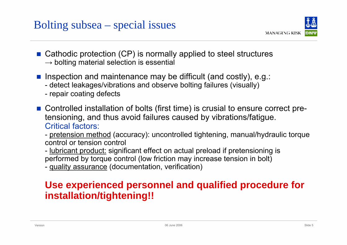
Bolting subsea – special issues
Cathodic protection (CP) is normally applied to steel structures→ bolting material selection is essential
Inspection and maintenance may be difficult (and costly), e.g.: - detect leakages/vibrations and observe bolting failures (visually)- repair coating defects
Controlled installation of bolts (first time) is crusial to ensure correct pre-tensioning, and thus avoid failures caused by vibrations/fatigue.Critical factors:- pretension method (accuracy): uncontrolled tightening, manual/hydraulic torquecontrol or tension control- lubricant product: significant effect on actual preload if pretensioning is performed by torque control (low friction may increase tension in bolt)- quality assurance (documentation, verification)
Use experienced personnel and qualified procedure for installation/tightening!!

Version Slide 606 June 2006
Bolting materials (common standards)
Alloys and chemical/mechanical requirements:
ASTM A 193 ”Alloy steel and stainless steel bolting materials for hightemperature service” (eks. ferritic steels Grade B7, B7M)
ASTM A 320 ”Alloy steel bolting materials for low temperature service” (eks. ferritic steels Grade L7, L7M)
ASTM A 354 ”Quenched and tempered alloy steel bolts, studs and otherexternally threaded fasteners”
- These standards reffere to AISI designations for chemical composition (e.g. AISI 4140, 4142 or 4145). SMYS will depend on heat treatment, shape and dimension.
- In general ”quenched and tempered” low alloyed bolts are frequently used for offshore applications
ISO 898-1 ”Mechanical properties of fasteners made of carbon steel and alloy steel – Part 1: Bolts, screws and studs
Version Slide 706 June 2006
Bolting materials (common standards) cont.
Dimensions, threads, tolerances:
ISO 898 Part 1 to 7
Additional requirements:
mechanical testing
inspection/quality control
Version Slide 806 June 2006
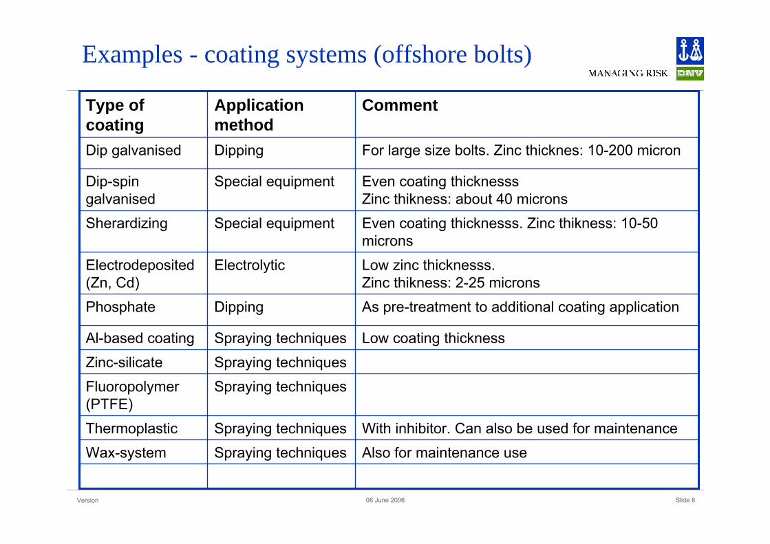
Examples - coating systems (offshore bolts)
Also for maintenance useSpraying techniquesWax-systemWith inhibitor. Can also be used for maintenanceSpraying techniquesThermoplastic
Spraying techniquesFluoropolymer(PTFE)
Spraying techniquesZinc-silicateLow coating thicknessSpraying techniquesAl-based coating
As pre-treatment to additional coating applicationDippingPhosphate
Low zinc thicknesss. Zinc thikness: 2-25 microns
ElectrolyticElectrodeposited(Zn, Cd)
Even coating thicknesss. Zinc thikness: 10-50 microns
Special equipmentSherardizing
Even coating thicknesssZinc thikness: about 40 microns
Special equipmentDip-spingalvanised
For large size bolts. Zinc thicknes: 10-200 micronDippingDip galvanised
CommentApplicationmethod
Type ofcoating
Version Slide 906 June 2006
Requirements / specifications
ANSI/API RP 17 & ISO 13628-1:2005ANSI/API RP 17¤Design and Operation of Subsea Production Systems –General Requirements and Recommendations
ISO 13628-1:2005, Petroleum and natural gas industries-Design and operation of subsea production systems-Part 1: General requirementsand recommendations

Version Slide 1006 June 2006
ANSI/API RP 17 & ISO 13628-1:2005 (cont.)If cathodic protection (CP) is ensured, bolting material used for piping system and equipment should generally be carbon or low-alloy steel, ref. ASTM A320 (L7 and L43) and ASTM A193 (B7 and B8M). Bolts with a diameter less than 10mm may be stainless steel type 316 (ISO 3506-1, Type A4) at temp. below 60 ºC.
Structural applications:- strength class should not exceed class 8.8 for bolts (ISO 898-1) and class 8 for nuts (ISO 898-2)- maximum actual allowable hardness: 300 HBW or 32 HRC (verified by spot testing)
Requirements / specifications

Version Slide 1106 June 2006
ANSI/API RP 17 & ISO 13628-1:2005 (cont.)In high corrosive environments and/or where CRA materials are used, corrosion-resistant bolting is recommended.- Alloy 625 (Ni-based) are required at ambient temperature in aerated seawater (ifCP cannot be ensured).- Other alloys can be used if properly documented
Requirements / specifications
Version Slide 1206 June 2006
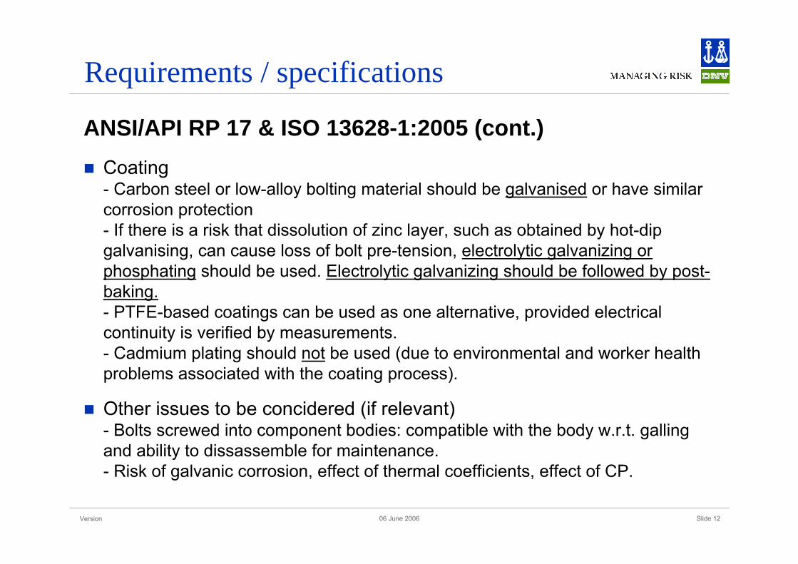
ANSI/API RP 17 & ISO 13628-1:2005 (cont.)Coating- Carbon steel or low-alloy bolting material should be galvanised or have similarcorrosion protection- If there is a risk that dissolution of zinc layer, such as obtained by hot-dip galvanising, can cause loss of bolt pre-tension, electrolytic galvanizing or phosphating should be used. Electrolytic galvanizing should be followed by post-baking.- PTFE-based coatings can be used as one alternative, provided electrical continuity is verified by measurements.- Cadmium plating should not be used (due to environmental and worker health problems associated with the coating process).
Other issues to be concidered (if relevant)- Bolts screwed into component bodies: compatible with the body w.r.t. gallingand ability to dissassemble for maintenance.- Risk of galvanic corrosion, effect of thermal coefficients, effect of CP.
Requirements / specifications

Version Slide 1306 June 2006
Requirements / specifications
NORSOK Standard M-001 Materials selection (Rev. 4, August 2004)
General: Carbon or low-alloyed bolting materials- maximum hardness of 300 HB (32 HRC) – verified by spot testing of each delivery, batch and size- for structural applications, strength class shall not exceed ISO 898 class 8.8 - hot dip galvanised (ASTM A153) or similar corrosion protection- if dissolution of zinc layer may cause loss of bolt pretension, phosphating shall be used- PTFE based coatings can be used (electrical continuity need to be verified by measurements)- compatible to component bodies w.r.t. galling and ability to disassemble the component for maintenance
Ambient temperature: Alloy 625 (seawater, no cathodic protection)
Version Slide 1406 June 2006
Failure mechanisms – subsea bolts
CorrosionHydrogen related mechanisms (cracking)- Hydrogen induced stress cracking (HISC)- Hydrogen embrittlement (HE)
Stress corrosion (SCC), ref. e.g. chloride stress corrosion
Corrosion fatigue
General corrosion
Local corrosion (pitting/crevice corrosion)
Galvanic corrosion
Galling, Fatigue, Overloading
Version Slide 1506 June 2006
Failure mechanisms – Corrosion (HISC/HE)
HISCProgressive cracking under influence of external or internal stresses, starting at metal/environment interface and propagating by absorption of nascent hydrogen at the crack tip. Electrochemical process (e.g. corrosion or cathodic protection) as hydrogen source. Bulk charging of hydrogen not required. Non-reversibleprocess.
HELoss of ductility due to absorption of nascent hydrogen in bulk material (“bulk charging”). Electrochemical or metallurgical process as hydrogen source. Reversible process, but may lead to cracking (surface or non-surface breaking) by brittle fracture under influence of external or internal stresses.
- Electroplating is generally considered to be a major cause of hydrogen absorption in bolts due to the release of hydrogen in this process. Absorbed hydrogen can be removed by post-baking (temperature >200 C).

Version Slide 1606 June 2006
Hydrogen induced failure mechanisms
HISC (hydrogen induced stress cracking) is caused by interaction between metal latticeand atomic hydrogen dissolved in the steel. External or internal stresses required.
HPIC (hydrogen pressure induced cracking) is cracking/fracture caused by pressurebuildup due to recombination of hydrogen atoms in accessible positions *. External or internal stresses not required.
SOHIC (Stress Oriented Hydrogen Induced Cracking) is a combination wherelongitudinal HPIC cracks are connected by transverse HISC cracks.
If the cracking is related to a corrosion process the description HISCC (hydrogen inducedstress corrosion cracking) is sometimes used.
SSC (sulphide stress cracking) is a sort of HISCC.
Hydrogen attack is reaction between hydrogen and carbides that causes a reduction in strength / cracking.
*) E.g. at pores, grain boundaries and inclusions.
Version Slide 1706 June 2006
Hydrogen induced failure mechanisms
Hydrogen sources:
Steel manufacturing- Large quantities of hydrogen may be dissolved in liquid steel- Humidity in air and chill moulds etc.
Coating- Acid cleaning- Electrolytic plating (metallic coatings)- Hydrogen may be removed by baking >200ºC
In service- Cathodic protection system (CP) - Corrosion processes
Version Slide 1806 June 2006
Failure mechanisms - HISC
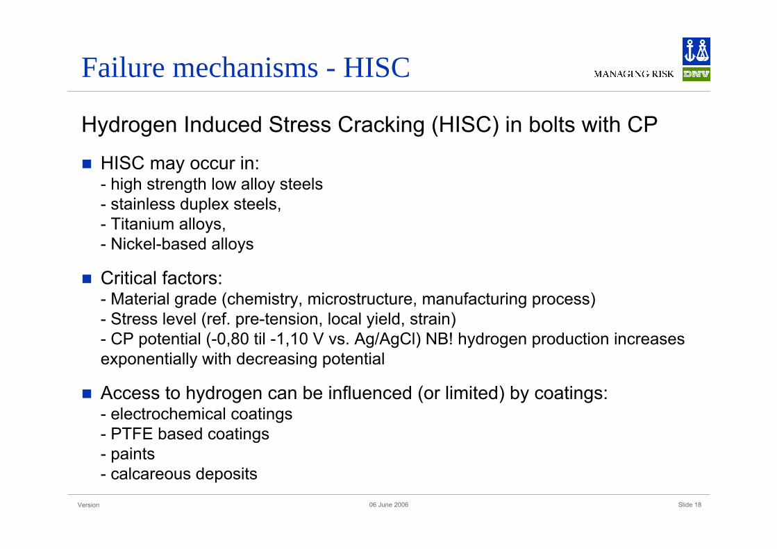
Hydrogen Induced Stress Cracking (HISC) in bolts with CP
HISC may occur in:- high strength low alloy steels- stainless duplex steels, - Titanium alloys, - Nickel-based alloys
Critical factors:- Material grade (chemistry, microstructure, manufacturing process)- Stress level (ref. pre-tension, local yield, strain)- CP potential (-0,80 til -1,10 V vs. Ag/AgCl) NB! hydrogen production increasesexponentially with decreasing potential
Access to hydrogen can be influenced (or limited) by coatings:- electrochemical coatings- PTFE based coatings- paints- calcareous deposits
Version Slide 1906 June 2006
Material grades – HISC sensitivity
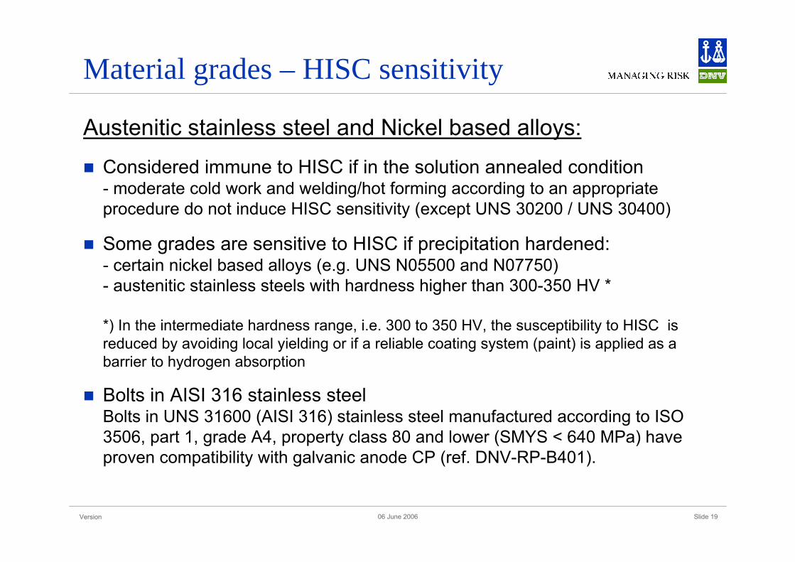
Austenitic stainless steel and Nickel based alloys:
Considered immune to HISC if in the solution annealed condition- moderate cold work and welding/hot forming according to an appropriateprocedure do not induce HISC sensitivity (except UNS 30200 / UNS 30400)
Some grades are sensitive to HISC if precipitation hardened:- certain nickel based alloys (e.g. UNS N05500 and N07750)- austenitic stainless steels with hardness higher than 300-350 HV *
*) In the intermediate hardness range, i.e. 300 to 350 HV, the susceptibility to HISC is reduced by avoiding local yielding or if a reliable coating system (paint) is applied as a barrier to hydrogen absorption
Bolts in AISI 316 stainless steelBolts in UNS 31600 (AISI 316) stainless steel manufactured according to ISO 3506, part 1, grade A4, property class 80 and lower (SMYS < 640 MPa) have proven compatibility with galvanic anode CP (ref. DNV-RP-B401).
Version Slide 2006 June 2006
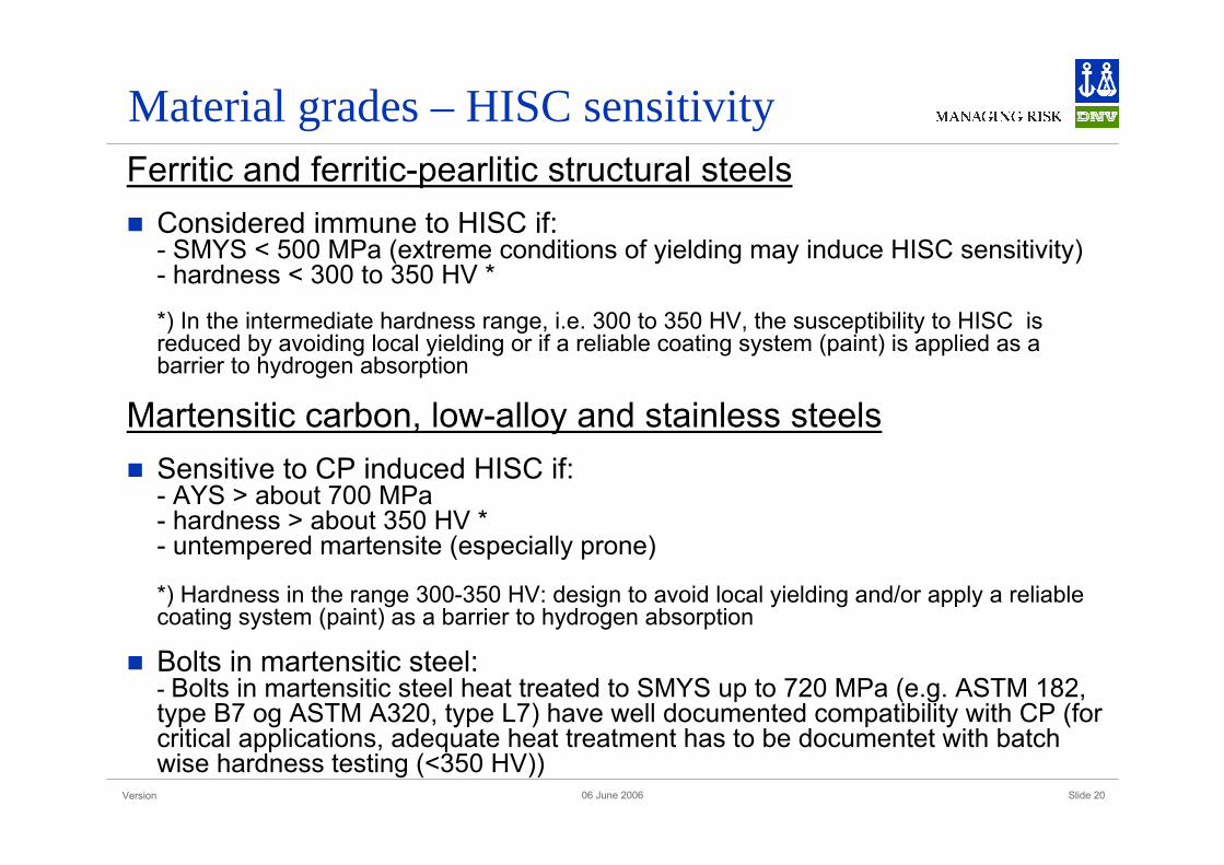
Material grades – HISC sensitivityFerritic and ferritic-pearlitic structural steels
Considered immune to HISC if:- SMYS < 500 MPa (extreme conditions of yielding may induce HISC sensitivity)- hardness < 300 to 350 HV *
*) In the intermediate hardness range, i.e. 300 to 350 HV, the susceptibility to HISC is reduced by avoiding local yielding or if a reliable coating system (paint) is applied as a barrier to hydrogen absorption
Martensitic carbon, low-alloy and stainless steelsSensitive to CP induced HISC if:- AYS > about 700 MPa- hardness > about 350 HV *- untempered martensite (especially prone)
*) Hardness in the range 300-350 HV: design to avoid local yielding and/or apply a reliable coating system (paint) as a barrier to hydrogen absorption
Bolts in martensitic steel:- Bolts in martensitic steel heat treated to SMYS up to 720 MPa (e.g. ASTM 182, type B7 og ASTM A320, type L7) have well documented compatibility with CP (for critical applications, adequate heat treatment has to be documentet with batchwise hardness testing (<350 HV))
Version Slide 2106 June 2006
Material grades – HISC sensitivity
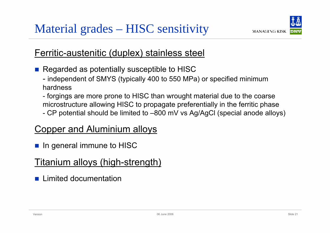
Ferritic-austenitic (duplex) stainless steel
Regarded as potentially susceptible to HISC - independent of SMYS (typically 400 to 550 MPa) or specified minimum hardness- forgings are more prone to HISC than wrought material due to the coarsemicrostructure allowing HISC to propagate preferentially in the ferritic phase- CP potential should be limited to –800 mV vs Ag/AgCl (special anode alloys)
Copper and Aluminium alloys
In general immune to HISC
Titanium alloys (high-strength)
Limited documentation
Version Slide 2206 June 2006
Failure mechanisms (cont.)
Stress corrosion cracking (SCC)
Chlorid stress corrosion cracking in high temp., oxygen containingseawater, without CP - stainless steel grades - Nickel alloys- Titanium grades, etc.
Fatigue (corrosion fatigue)
Caused by vibrations and missing pre-tensioning
Prevent fatigue failures:- controlled tightening- select materials with improved fatigue properties
Version Slide 2306 June 2006
Failure mechanisms (cont.)
Galling
Mechanism:- a severe form of adhesive wear which occurs during sliding contact of onesurface relative to another.
Most sensitive materials- austenitic stainless steel, Ni-Cr alloys (and some Titanium alloys), galvanizedsteel
Problem reduced by- using coarse threads- using appropriate lubricants- selecting material combinations (bolt-structur / bolt-nut) with different resistance(property)- qualifying procedure for tightening
Version Slide 2406 June 2006
Failure mechanisms (cont.)
Overloading
High strength bolts are frequently used for structures and pressuresystems to avoid overloading
If low friction lubricants are applied pre-tensioning of bolts may causeoverloading
Version Slide 2506 June 2006
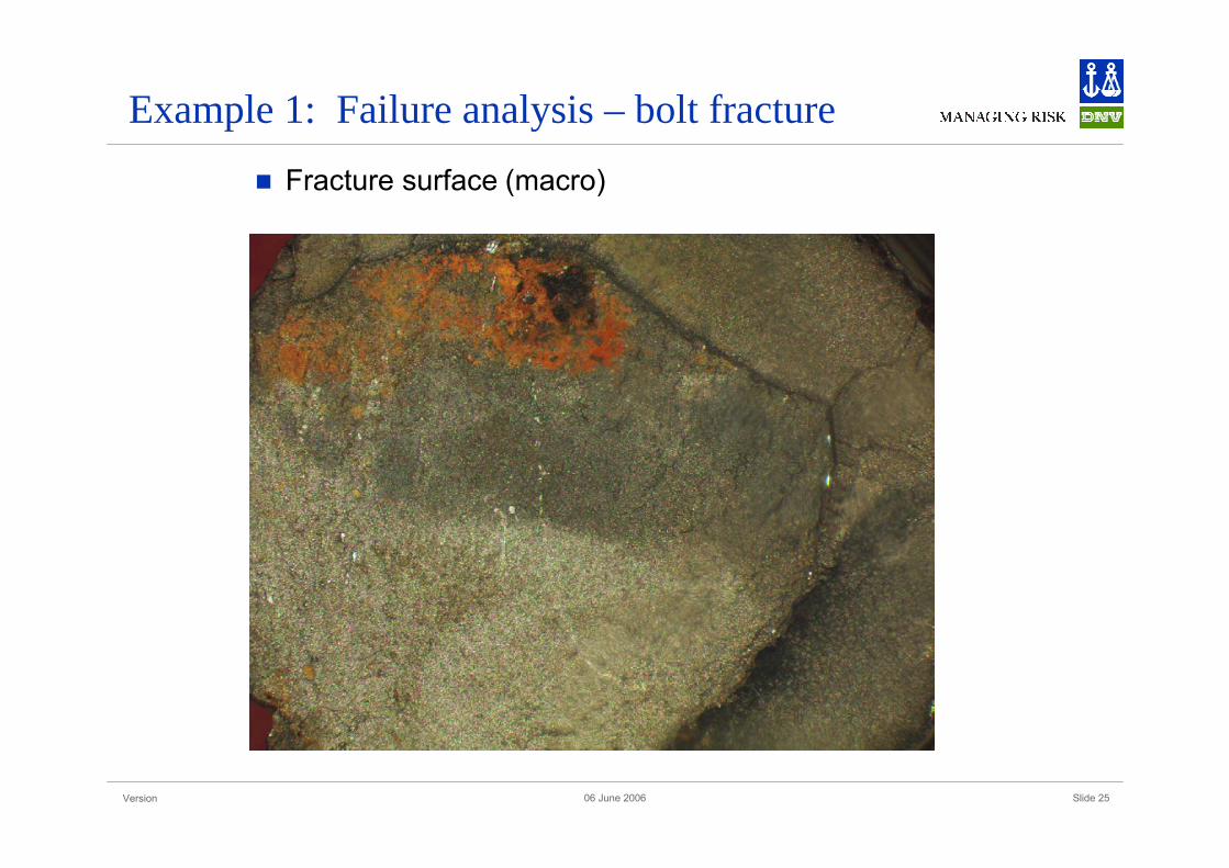
Example 1: Failure analysis – bolt fracture
Fracture surface (macro)
Version Slide 2606 June 2006
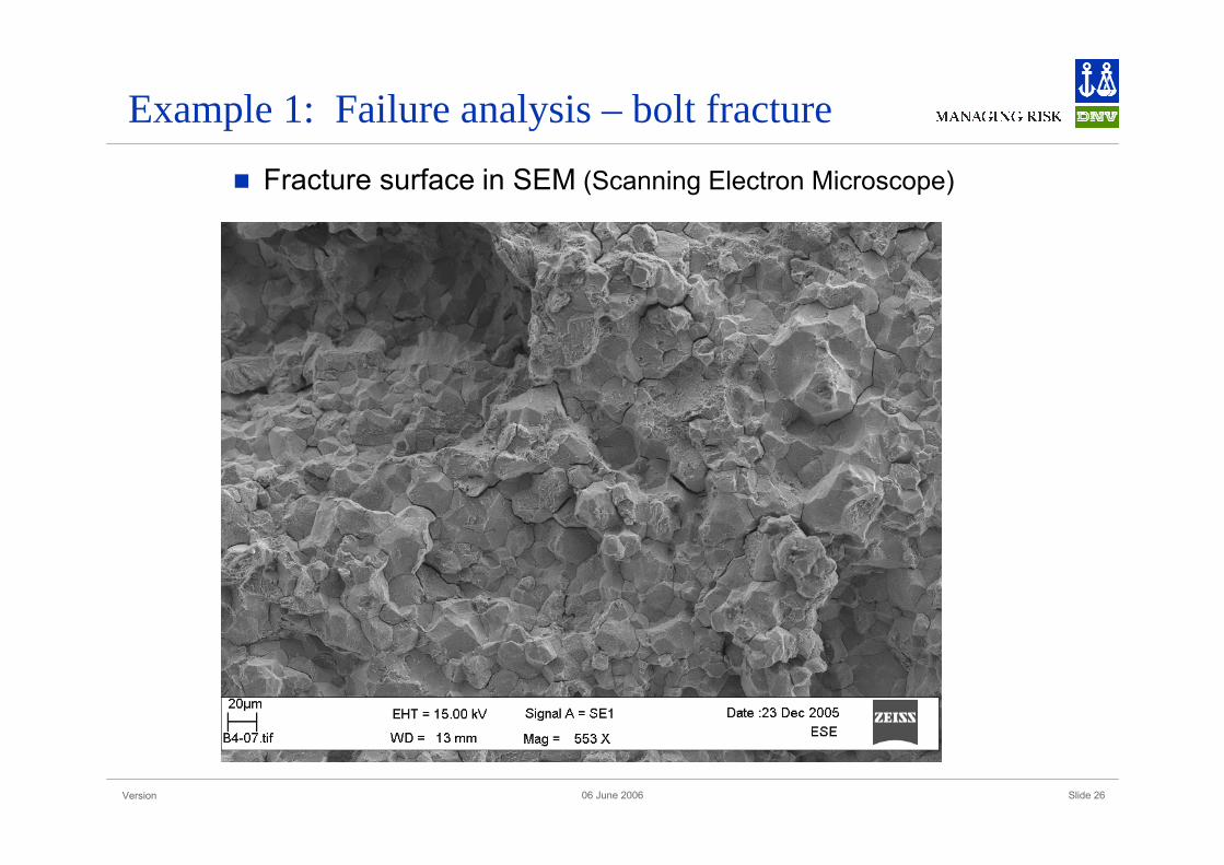
Example 1: Failure analysis – bolt fracture
Fracture surface in SEM (Scanning Electron Microscope)
Version Slide 2706 June 2006
Example 1: Failure analysis – bolt fracture
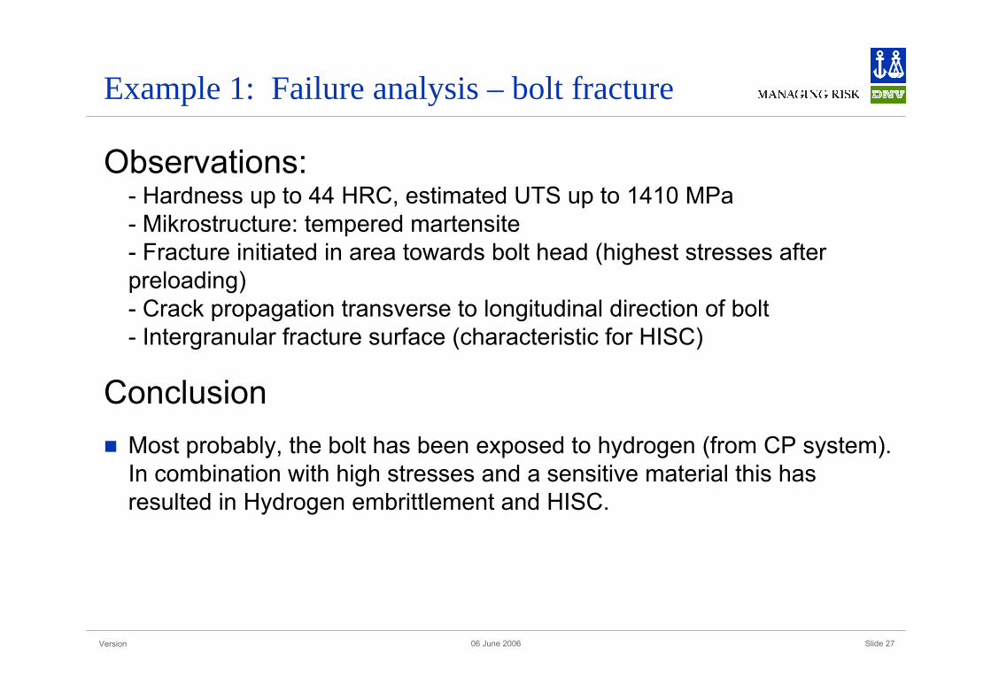
Observations: - Hardness up to 44 HRC, estimated UTS up to 1410 MPa- Mikrostructure: tempered martensite- Fracture initiated in area towards bolt head (highest stresses afterpreloading) - Crack propagation transverse to longitudinal direction of bolt - Intergranular fracture surface (characteristic for HISC)
ConclusionMost probably, the bolt has been exposed to hydrogen (from CP system). In combination with high stresses and a sensitive material this has resulted in Hydrogen embrittlement and HISC.
Version Slide 2806 June 2006
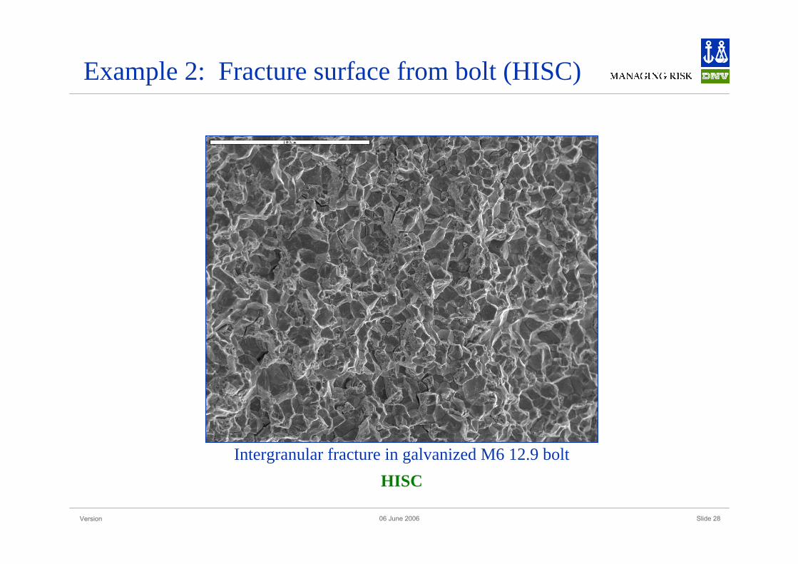
Example 2: Fracture surface from bolt (HISC)
Intergranular fracture in galvanized M6 12.9 boltHISC

Version Slide 2906 June 2006
Testing
Bolting materials for subsea applications (with CP)Need to qualify candidate materials with respect to susceptibility to HE and HISC (combination)
However, no test methods are generally “accepted” to verify CP compatibility for materials/systems
Alternative test methods:- SSRT (compare relative sensitivity of similar materials, e.g. martensitic steels) - Tensile testing (constant load) and bend testing (constant strain) in e.g. seawater with CP may be applied for more quantitative testing - CTOD (with CP)- Full scale comparative testing of material candidates in simulated environments
Coating (pain systems)Standard test methods to determine resistance to cathodic disbonding
Version Slide 3006 June 2006
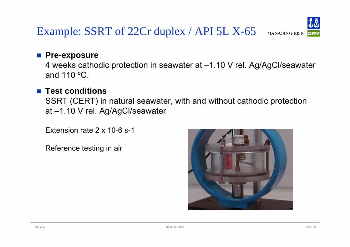
Example: SSRT of 22Cr duplex / API 5L X-65
Pre-exposure4 weeks cathodic protection in seawater at –1.10 V rel. Ag/AgCl/seawater and 110 ºC.
Test conditionsSSRT (CERT) in natural seawater, with and without cathodic protection at –1.10 V rel. Ag/AgCl/seawater
Extension rate 2 x 10⁻⁶ s-1
Reference testing in air
Version Slide 3106 June 2006
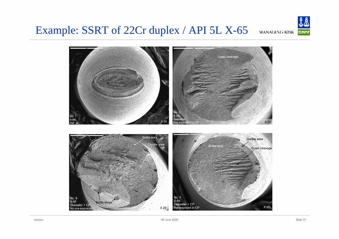
Example: SSRT of 22Cr duplex / API 5L X-65

Version Slide 3206 June 2006
Example: SSRT of 22Cr duplex / API 5L X-65
Conclusions
Hydrogen charging causes slight/moderate HE of both materials.
Both materials are susceptible to HISC but the intrinsic susceptibility of duplex stainless steel is higher.
Pre-exposure to CP has no effect on HISC of API 5L X65.
Pre-exposure to CP may enhance HISC of duplex stainless steel significantly.
Simultaneous plastic straining and hydrogen adsorption is required for HISC of these materials.

Version Slide 3306 June 2006
Example: Submerged testing with CP, DNV Bergen
Version Slide 3406 June 2006