
Bolt tightening solutions - STC Forniture · Bolt tightening tool type Introduction Hydraulic...
128
Bolt tightening solutions We offer a complete and dynamic range of bolting tools including hydraulic bolt tensioners and hydraulic torque wrenches, as well as pneumatic and electric transducerized nutrunners.
Transcript of Bolt tightening solutions - STC Forniture · Bolt tightening tool type Introduction Hydraulic...

Bolt tightening solutions
We offer a complete and dynamic range of bolting tools including hydraulic bolt tensioners and hydraulic torque wrenches, as well as pneumatic and electric transducerized nutrunners.
2
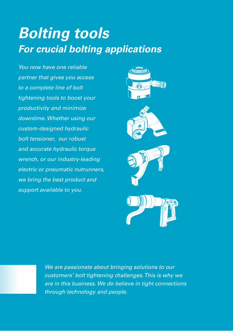
Bolting tools For crucial bolting applications
You now have one reliable
partner that gives you access
to a complete line of bolt
tightening tools to boost your
productivity and minimize
downtime. Whether using our
custom-designed hydraulic
bolt tensioner, our robust
and accurate hydraulic torque
wrench, or our industry-leading
electric or pneumatic nutrunners,
we bring the best product and
support available to you.
We are passionate about bringing solutions to our customers’ bolt tightening challenges. This is why we are in this business. We do believe in tight connections through technology and people.
3
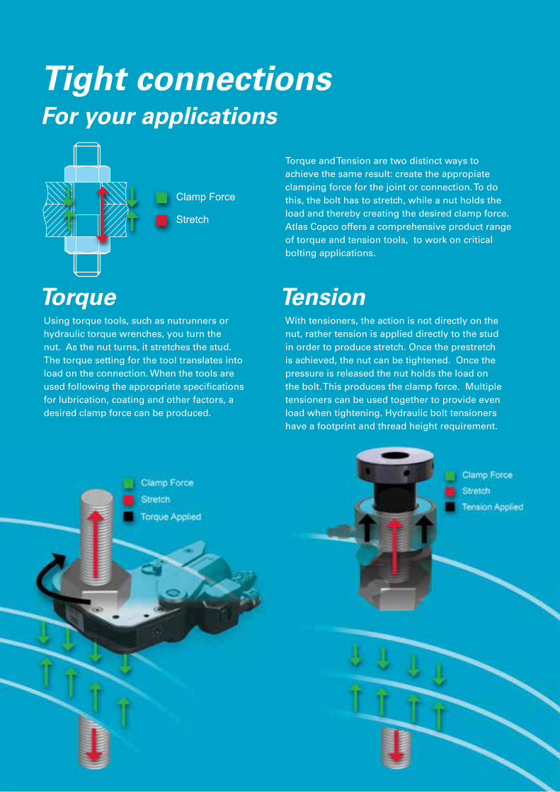
Clamp Force
Stretch
TorqueWith tensioners, the action is not directly on the nut, rather tension is applied directly to the stud in order to produce stretch. Once the prestretch is achieved, the nut can be tightened. Once the pressure is released the nut holds the load on the bolt. This produces the clamp force. Multiple tensioners can be used together to provide even load when tightening. Hydraulic bolt tensioners have a footprint and thread height requirement.
TensionUsing torque tools, such as nutrunners or hydraulic torque wrenches, you turn the nut. As the nut turns, it stretches the stud. The torque setting for the tool translates into load on the connection. When the tools are used following the appropriate specifications for lubrication, coating and other factors, a desired clamp force can be produced.
Tight connectionsFor your applications
Torque and Tension are two distinct ways to achieve the same result: create the appropiate clamping force for the joint or connection. To do this, the bolt has to stretch, while a nut holds the load and thereby creating the desired clamp force. Atlas Copco offers a comprehensive product range of torque and tension tools, to work on critical bolting applications.
4
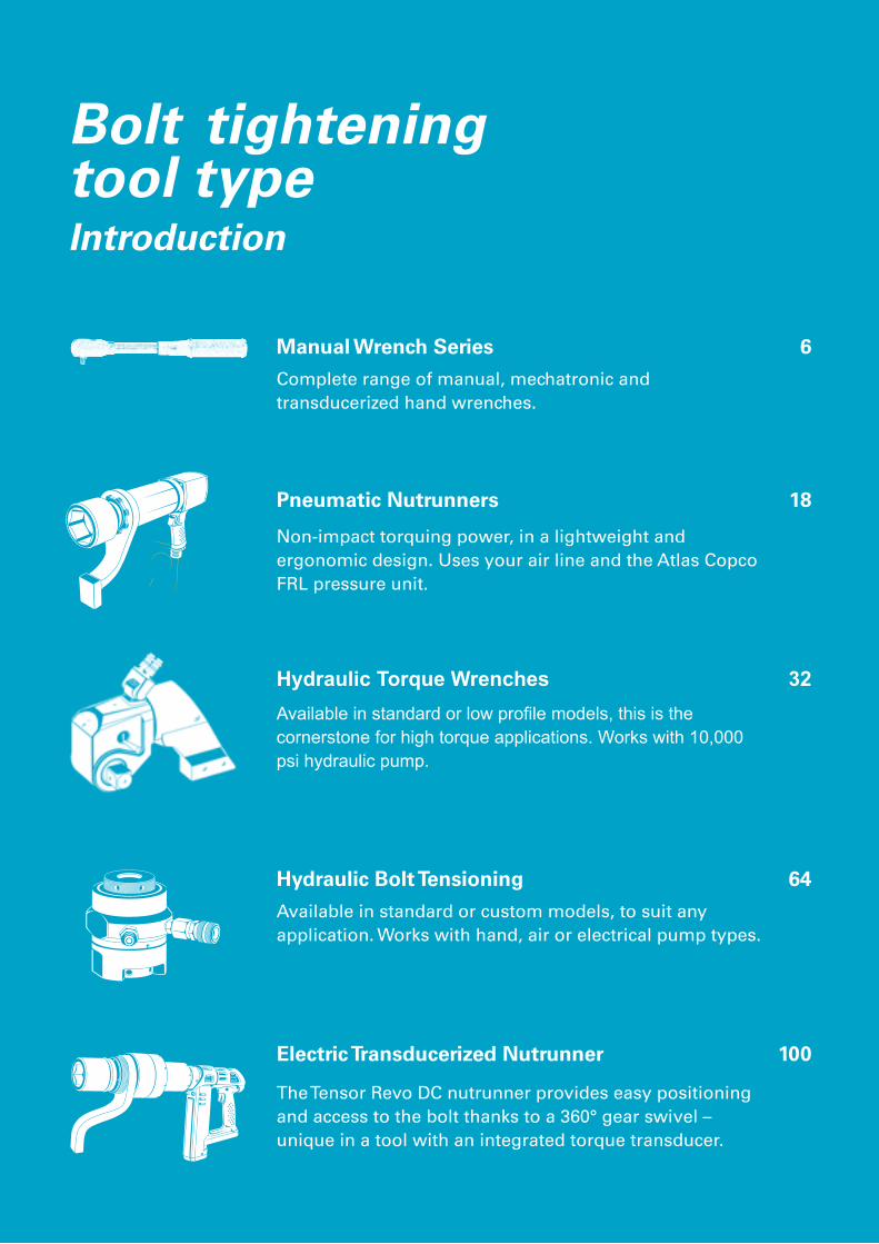
Bolt tightening tool type Introduction
Hydraulic Torque Wrenches 32
Electric Transducerized Nutrunner 100
Hydraulic Bolt Tensioning 64
Manual Wrench Series 6
Pneumatic Nutrunners 18
Available in standard or custom models, to suit any application. Works with hand, air or electrical pump types.
Complete range of manual, mechatronic and transducerized hand wrenches.
Available in standard or low profile models, this is the cornerstone for high torque applications. Works with 10,000 psi hydraulic pump.
Non-impact torquing power, in a lightweight and ergonomic design. Uses your air line and the Atlas Copco FRL pressure unit.
The Tensor Revo DC nutrunner provides easy positioning and access to the bolt thanks to a 360° gear swivel – unique in a tool with an integrated torque transducer.
5
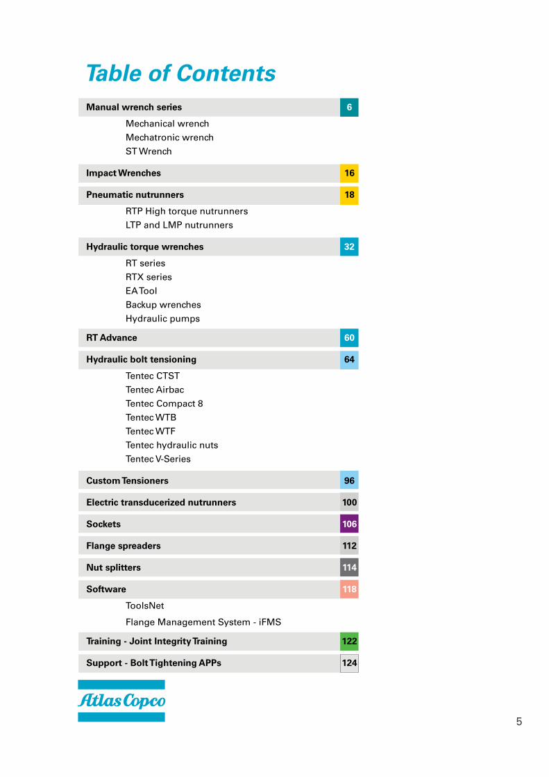
Table of ContentsManual wrench series 6
Mechanical wrench
Mechatronic wrench
ST Wrench
Impact Wrenches 16
Pneumatic nutrunners 18
RTP High torque nutrunners
LTP and LMP nutrunners
Hydraulic torque wrenches 32
RT series
RTX series
EA Tool
Backup wrenches
Hydraulic pumps
RT Advance 60
Hydraulic bolt tensioning 64
Tentec CTST
Tentec Airbac
Tentec Compact 8
Tentec WTB
Tentec WTF
Tentec hydraulic nuts
Tentec V-Series
Custom Tensioners 96
Electric transducerized nutrunners 100
Sockets 106
Flange spreaders 112
Nut splitters 114
Software 118
ToolsNet
Flange Management System - iFMS
Training - Joint Integrity Training 122
Support - Bolt Tightening APPs 124
6
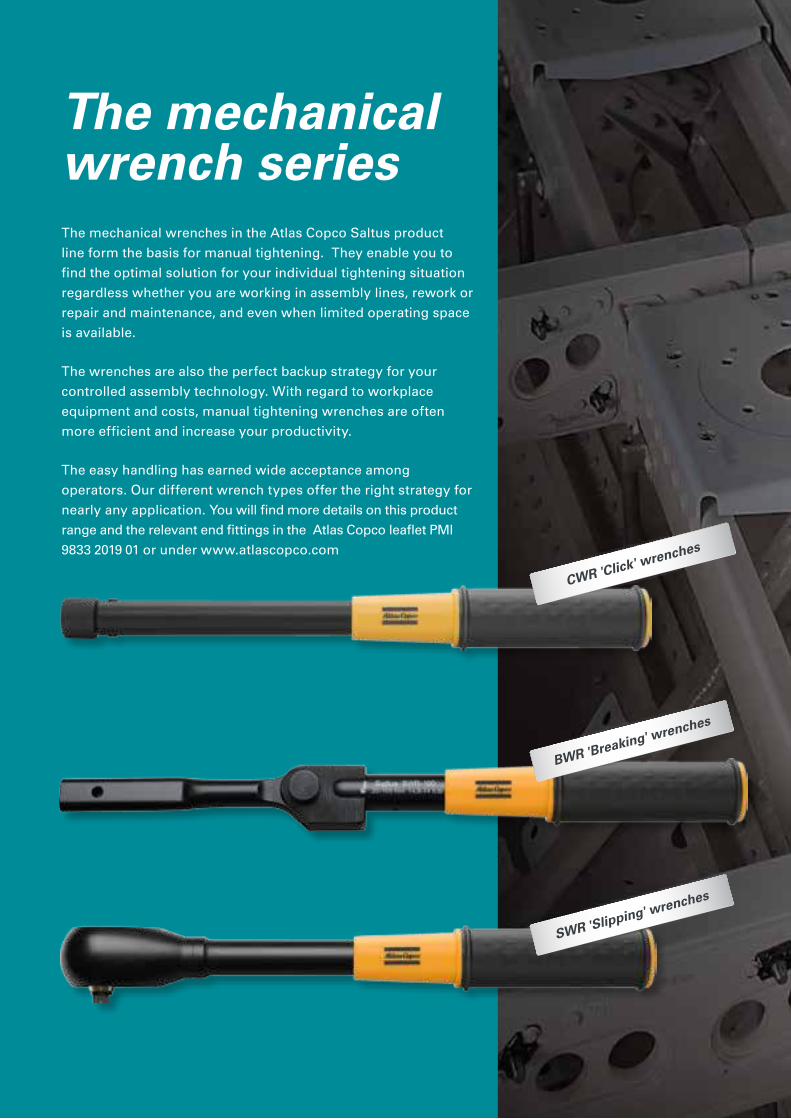
The mechanical wrench seriesThe mechanical wrenches in the Atlas Copco Saltus product
line form the basis for manual tightening. They enable you to
find the optimal solution for your individual tightening situation
regardless whether you are working in assembly lines, rework or
repair and maintenance, and even when limited operating space
is available.
The wrenches are also the perfect backup strategy for your
controlled assembly technology. With regard to workplace
equipment and costs, manual tightening wrenches are often
more efficient and increase your productivity.
The easy handling has earned wide acceptance among
operators. Our different wrench types offer the right strategy for
nearly any application. You will find more details on this product
range and the relevant end fittings in the Atlas Copco leaflet PMI
9833 2019 01 or under www.atlascopco.com
BWR 'Breaking' wrenches
CWR 'Click' wrenches
SWR 'Slipping' wrenches
7
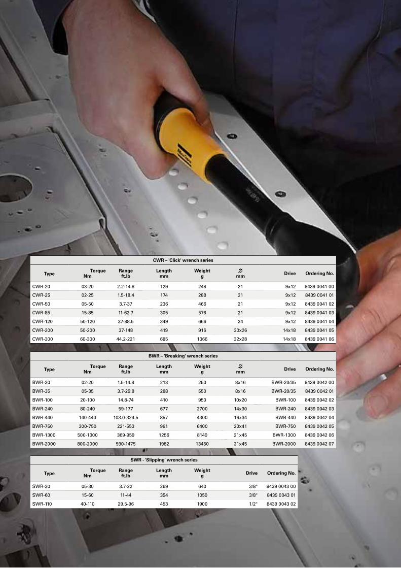
BWR – 'Breaking' wrench series
TypeTorque
NmRangeft.lb
Length mm
Weight g
∅ mm Drive Ordering No.
BWR-20 02-20 1.5-14.8 213 250 8x16 BWR-20/35 8439 0042 00
BWR-35 05-35 3.7-25.8 288 550 8x16 BWR-20/35 8439 0042 01
BWR-100 20-100 14.8-74 410 950 10x20 BWR-100 8439 0042 02
BWR-240 80-240 59-177 677 2700 14x30 BWR-240 8439 0042 03
BWR-440 140-440 103.0-324.5 857 4300 16x34 BWR-440 8439 0042 04
BWR-750 300-750 221-553 961 6400 20x41 BWR-750 8439 0042 05
BWR-1300 500-1300 369-959 1256 8140 21x45 BWR-1300 8439 0042 06
BWR-2000 800-2000 590-1475 1982 13450 21x45 BWR-2000 8439 0042 07
SWR - 'Slipping' wrench series
TypeTorque
NmRangeft.lb
Length mm
Weight g Drive Ordering No.
SWR-30 05-30 3.7-22 269 640 3/8" 8439 0043 00
SWR-60 15-60 11-44 354 1050 3/8" 8439 0043 01
SWR-110 40-110 29.5-96 453 1900 1/2" 8439 0043 02
CWR – 'Click' wrench series
TypeTorque
NmRangeft.lb
Length mm
Weight g
∅ mm Drive Ordering No.
CWR-20 03-20 2.2-14.8 129 248 21 9x12 8439 0041 00
CWR-25 02-25 1.5-18.4 174 288 21 9x12 8439 0041 01
CWR-50 05-50 3.7-37 236 466 21 9x12 8439 0041 02
CWR-85 15-85 11-62.7 305 576 21 9x12 8439 0041 03
CWR-120 50-120 37-88.5 349 666 24 9x12 8439 0041 04
CWR-200 50-200 37-148 419 916 30x26 14x18 8439 0041 05
CWR-300 60-300 44.2-221 685 1366 32x28 14x18 8439 0041 06
8
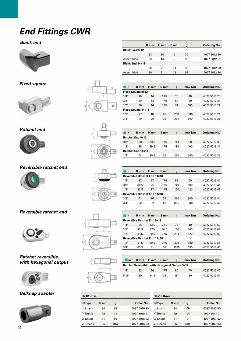
Blank end
Belknap adapter
in B mm H mm S mm g max Nm Ordering No.
Fixed Square 9x12
1/4" 20 14 17.5 76 40 4027 5013 20
3/8" 20 14 17.5 82 80 4027 5013 21
1/2" 20 14 17.5 71 100 4027 5013 22
Fixed Square 14x18
1/2" 27 18 25 203 300 4027 5013 24
3/4" 40 25 25 396 650 4027 5013 25
in B mm H mm S mm g max Nm Ordering No.
Reversible Ratchet End 9x12
1/4" 25 13.5 21.5 77 49 4027 5013 60
3/8" 33.5 17.5 30.5 160 100 4027 5013 61
1/2" 41.5 20.5 37.5 291 120 4027 5013 62
Reversible Ratchet End 14x18
1/2" 41.5 20.5 37.5 339 300 4027 5013 64
3/4" 63.5 31 70 1155 650 4027 5013 65
in B mm H mm S mm g max Nm Ordering No.
Ratchet End 9x12
3/8" 38 29.5 17.5 140 80 4027 5013 30
1/2" 38 29.5 17.5 180 100 4027 5013 31
Ratchet End 14x18
1/2" 44 29.5 25 230 300 4027 5013 33
in B mm H mm S mm g max Nm Ordering No.
Ratchet Reversible. with Hexagonal Output 9x12
1/4" 22 14 17.5 60 40 4027 5013 80
5/16" 29 14.5 28 117 80 4027 5013 81
in B mm H mm S mm g max Nm Ordering No.
Reversible Ratchet End 14x18
1/4" 27 27 17.5 68 50 4027 5013 40
3/8" 36.5 25 17.5 140 100 4027 5013 41
1/2" 33.5 37 17.5 150 120 4027 5013 42
Reversible Ratchet End 14x18
1/2" 41 26 25 320 300 4027 5013 44
3/4" 62 32 46 865 800 4027 5013 45
9x12 Drive
Type S mm g Order No.
J-Shank 24 68 4027 5016 90
Y-Shank 29 71 4027 5016 91
X-Shank 31 86 4027 5016 92
Z- Shank 56 314 4027 5016 93
B mm H mm S mm g Ordering No.
Blank End 9x12
23 14 9 30 4027 5012 20
Assembled 23 14 9 30 4027 5012 21
Blank End 14x18
30 21 13 98 4027 5012 23
Assembled 30 21 13 98 4027 5012 24
14x18 Drive
Type S mm g Order No.
J-Shank 24 105 4027 5017 00
Y-Shank 29 104 4027 5017 01
X-Shank 31 121 4027 5017 02
Z- Shank 56 349 4027 5017 03
End Fittings CWR
Fixed square
Reversible ratchet end
Reversible ratchet end
Ratchet end
Ratchet reversible, with hexagonal output
9
22 • ATLAS COPCO - MECHANICAL WRENCHES
BWR 20/35
in x mm B mm H mm S mm g max Nm Ordering No.
1/4 x 40 36 40 21 145 25 4027 5005 25
1/4 x 70 38 70 21 165 25 4027 5005 26
3/8 x 40 36 40 21 145 85 4027 5005 27
3/8 x 70 36 70 21 170 85 4027 5005 28
1/2 x 45 36 45 21 150 85 4027 5005 29
1/2 x 70 36 70 21 195 85 4027 5005 30
BWR 240
in x mm B mm H mm S mm g max Nm Ordering No.
1/2 x 45 48 45 31 300 240 4027 5005 44
1/2 x 70 48 70 31 330 240 4027 5005 45
BWR 1300/2000
in x mm B mm H mm S mm g max Nm Ordering No.
3/4 x 70 85 70 58 1700 1000 4027 5005 60
1 x 80 85 80 58 2000 2000 4027 5005 61
BWR 750
in x mm B mm H mm S mm g max Nm Ordering No.
3/4 x 70 72 70 58 1250 750 4027 5005 55
BWR 440
in x mm B mm H mm S mm g max Nm Ordering No.
3/4 x 70 72 70 58 1100 440 4027 5005 50
BWR 100
in x mm B mm H mm S mm g max Nm Ordering No.
3/8 x 40 48 40 30 270 100 4027 5005 36
3/8 x 70 48 70 30 31 100 4027 5005 37
1/2 x 45 48 40 30 285 100 4027 5005 38
1/2 x 70 48 70 30 320 100 4027 5005 39
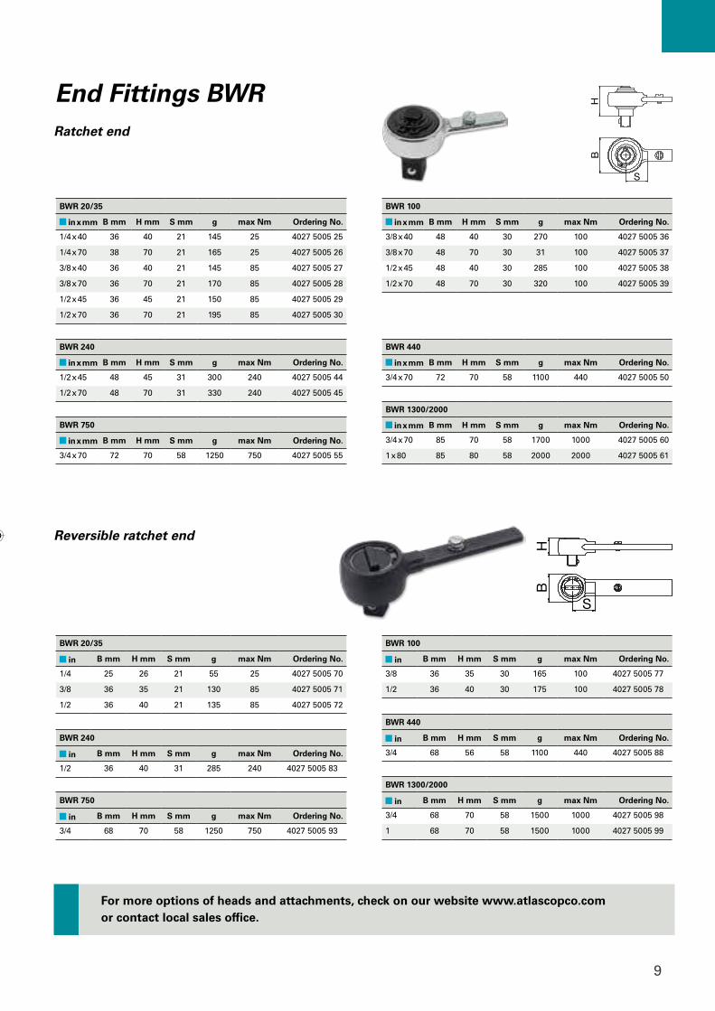
Ratchet End
Reversible Ratchet End
BWR 20/35
in B mm H mm S mm g max Nm Ordering No.
1/4 25 26 21 55 25 4027 5005 70
3/8 36 35 21 130 85 4027 5005 71
1/2 36 40 21 135 85 4027 5005 72
BWR 100
in B mm H mm S mm g max Nm Ordering No.
3/8 36 35 30 165 100 4027 5005 77
1/2 36 40 30 175 100 4027 5005 78
BWR 240
in B mm H mm S mm g max Nm Ordering No.
1/2 36 40 31 285 240 4027 5005 83
BWR 440
in B mm H mm S mm g max Nm Ordering No.
3/4 68 56 58 1100 440 4027 5005 88
BWR 750
in B mm H mm S mm g max Nm Ordering No.
3/4 68 70 58 1250 750 4027 5005 93
BWR 1300/2000
in B mm H mm S mm g max Nm Ordering No.
3/4 68 70 58 1500 1000 4027 5005 98
1 68 70 58 1500 1000 4027 5005 99
Reversible ratchet end
Ratchet end
End Fittings BWR
For more options of heads and attachments, check on our website www.atlascopco.com or contact local sales office.
10
D
C
AB
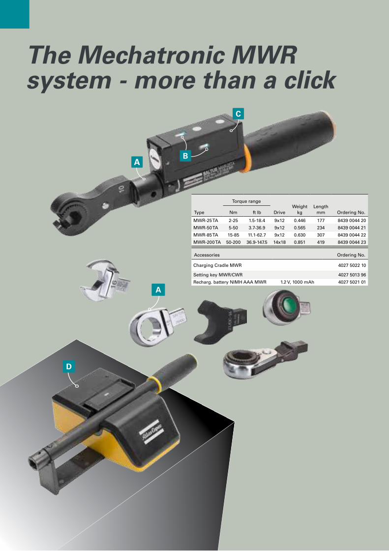
The Mechatronic MWR system - more than a click
A
Type
Torque range
DriveWeight
kgLength
mm Ordering No.Nm ft lb
MWR-25 TA 2-25 1.5-18.4 9x12 0.446 177 8439 0044 20
MWR-50 TA 5-50 3.7-36.9 9x12 0.565 234 8439 0044 21
MWR-85 TA 15-85 11.1-62.7 9x12 0.630 307 8439 0044 22
MWR-200 TA 50-200 36.9-147.5 14x18 0.851 419 8439 0044 23
Accessories Ordering No.
Charging Cradle MWR 4027 5022 10
Setting key MWR/CWR 4027 5013 96
Recharg. battery NIMH AAA MWR 1.2 V, 1000 mAh 4027 5021 01
11
A Thanks to a standard drive (9x12 and 14x18) , the operator can always find the perfect end fitting for his application.
B Operator can always know if a wrench is ready to work, and if the tightening was correct, by looking at the onboard LEDs.
C Thanks to the wireless connection the operator is free to move around and to access bolt location.
D The charging cradle is a stable holder and a battery charger, making sure that the tools are always ready to perform their tasks. Shift after shift.
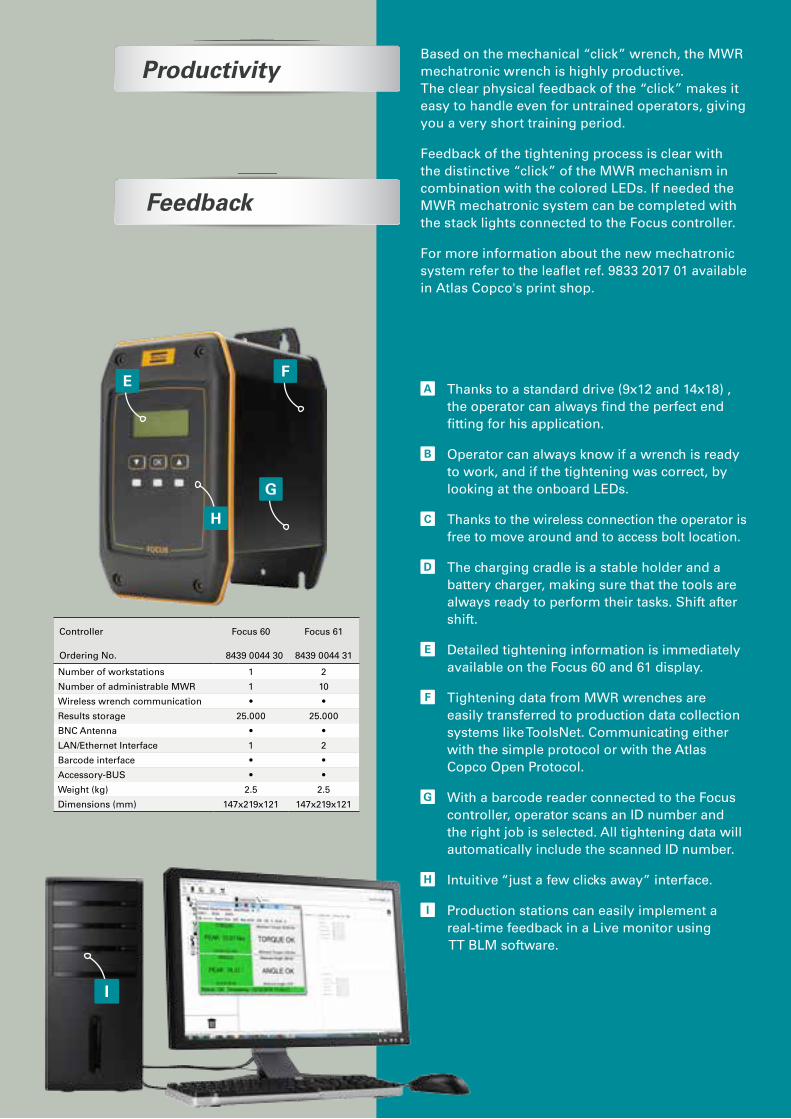
E Detailed tightening information is immediately available on the Focus 60 and 61 display.
F Tightening data from MWR wrenches are easily transferred to production data collection systems like ToolsNet. Communicating either with the simple protocol or with the Atlas Copco Open Protocol.
G With a barcode reader connected to the Focus controller, operator scans an ID number and the right job is selected. All tightening data will automatically include the scanned ID number.
H Intuitive “just a few clicks away” interface.
I Production stations can easily implement a real-time feedback in a Live monitor using TT BLM software.
FE
G
H
Based on the mechanical “click” wrench, the MWR mechatronic wrench is highly productive. The clear physical feedback of the “click” makes it easy to handle even for untrained operators, giving you a very short training period.
Feedback of the tightening process is clear with the distinctive “click” of the MWR mechanism in combination with the colored LEDs. If needed the MWR mechatronic system can be completed with the stack lights connected to the Focus controller.
For more information about the new mechatronic system refer to the leaflet ref. 9833 2017 01 available in Atlas Copco's print shop.
Productivity
Feedback
I
Controller
Ordering No.
Focus 60
8439 0044 30
Focus 61
8439 0044 31
Number of workstations 1 2
Number of administrable MWR 1 10
Wireless wrench communication • •
Results storage 25.000 25.000
BNC Antenna • •
LAN/Ethernet Interface 1 2
Barcode interface • •
Accessory-BUS • •
Weight (kg) 2.5 2.5
Dimensions (mm) 147x219x121 147x219x121
12
A
B
D
F
G
H
E
C
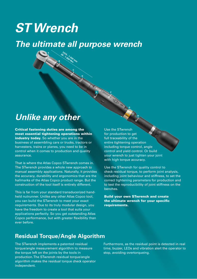
147.5 - 1 344 mm
30 - 1 000 Nm
Unlike any otherCritical fastening duties are among the most essential tightening operations within industry today. So whether you are in the business of assembling cars or trucks, tractors or harvesters, trains or planes, you need to be in control when it comes to production and quality assurance.
That is where the Atlas Copco STwrench comes in. The STwrench provides a whole new approach to manual assembly applications. Naturally, it provides the accuracy, durability and ergonomics that are the hallmarks of the Atlas Copco product range. But the construction of the tool itself is entirely different.
This is far from your standard transduce r ized hand-held nutrunner. Unlike any other Atlas Copco tool, you can build the STwrench to meet your exact requirements. Due to its truly modular design, you have the freedom to create a tool that suits your applications perfectly. So you get outstanding Atlas Copco performance, but with greater flexibility than ever before.
The STwrench implements a patented residual torque/angle measurement algorithm to measure the torque left on the joints by the tools in production. The STwrench residual torque/angle algorithm makes the residual torque check operator independent.
Use the STwrench for production to get full traceability of the entire tightening oper ation including torque control, angle control and yield control. Or build your wrench to just tighten your joint with high torque accuracy.
Use the STwrench for quality control to check residual torque, to perform joint analysis, including joint behaviour and stiffness, to set the correct tightening parameters for production and to test the reproducibility of joint stiffness on the benches.
Build your own STwrench and create the ultimate wrench for your specific requirements.
Residual Torque/Angle AlgorithmFurthermore, as the residual point is detected in real time, buzzer, LEDs and vibration alert the operator to stop, avoiding overtorqueing.
ST WrenchThe ultimate all purpose wrench

13
FeaturesA Interchangeable end fittings with
patented recognition technology for PSET selection. Full traceability of various applications.
B Optional advanced electronic gyroscope for precise angle measurement.
C Low clearance compact head to get better accessibility and stability of operation.
D Bright LED headlight in front of the smartHEAD to illuminate dark spaces.
E The communication interfaces are USB or Wi-Fi thanks to the radio module. It is also possible to have communication with Power Focus via Wi-Fi or Bluetooth. Barcode module can be added to improve traceability and automatically start the tests.
F Easy-to-read display that can be read at angles of up to 180°.
G Four signal lights for improved operator feedback visible at 360°. Three special LED signals guide the operator for accurate tightening and measuring control.
H Ergonomic vibrating handle to ensure precise use.
14
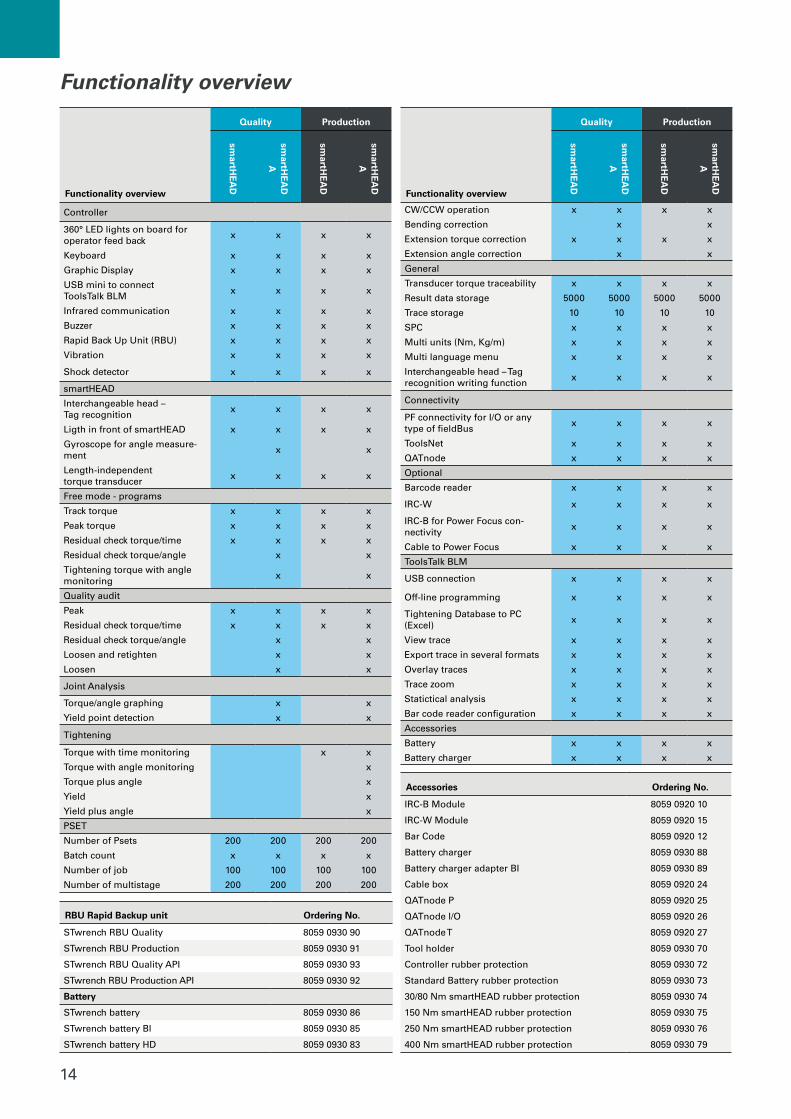
Functionality overview
Quality Production
smartH
EA
D
smartH
EA
D
A
smartH
EA
D
smartH
EA
D
A
Controller
360° LED lights on board for operator feed back
x x x x
Keyboard x x x x
Graphic Display x x x x
USB mini to connect ToolsTalk BLM
x x x x
Infrared communication x x x x
Buzzer x x x x
Rapid Back Up Unit (RBU) x x x x
Vibration x x x x
Shock detector x x x x
smartHEAD
Interchangeable head – Tag recognition
x x x x
Ligth in front of smartHEAD x x x x
Gyroscope for angle measure-ment
x x
Length-independent torque transducer
x x x x
Free mode - programs
Track torque x x x x
Peak torque x x x x
Residual check torque/time x x x x
Residual check torque/angle x x
Tightening torque with angle monitoring
x x
Quality audit
Peak x x x x
Residual check torque/time x x x x
Residual check torque/angle x x
Loosen and retighten x x
Loosen x x
Joint Analysis
Torque/angle graphing x x
Yield point detection x x
Tightening
Torque with time monitoring x x
Torque with angle monitoring x
Torque plus angle x
Yield x
Yield plus angle x
PSET
Number of Psets 200 200 200 200
Batch count x x x x
Number of job 100 100 100 100
Number of multistage 200 200 200 200
Functionality overview
Quality Production
smartH
EA
D
smartH
EA
D
A
smartH
EA
D
smartH
EA
D
A
CW/CCW operation x x x x
Bending correction x x
Extension torque correction x x x x
Extension angle correction x x
General
Transducer torque traceability x x x x
Result data storage 5000 5000 5000 5000
Trace storage 10 10 10 10
SPC x x x x
Multi units (Nm, Kg/m) x x x x
Multi language menu x x x x
Interchangeable head – Tag recognition writing function
x x x x
Connectivity
PF connectivity for I/O or any type of fieldBus
x x x x
ToolsNet x x x x
QATnode x x x x
Optional
Barcode reader x x x x
IRC-W x x x x
IRC-B for Power Focus con-nectivity
x x x x
Cable to Power Focus x x x x
ToolsTalk BLM
USB connection x x x x
Off-line programming x x x x
Tightening Database to PC (Excel)
x x x x
View trace x x x x
Export trace in several formats x x x x
Overlay traces x x x x
Trace zoom x x x x
Statictical analysis x x x x
Bar code reader configuration x x x x
Accessories
Battery x x x x
Battery charger x x x x
RBU Rapid Backup unit Ordering No.
STwrench RBU Quality 8059 0930 90
STwrench RBU Production 8059 0930 91
STwrench RBU Quality API 8059 0930 93
STwrench RBU Production API 8059 0930 92
Battery
STwrench battery 8059 0930 86
STwrench battery Bl 8059 0930 85
STwrench battery HD 8059 0930 83
Accessories Ordering No.
IRC-B Module 8059 0920 10
IRC-W Module 8059 0920 15
Bar Code 8059 0920 12
Battery charger 8059 0930 88
Battery charger adapter BI 8059 0930 89
Cable box 8059 0920 24
QATnode P 8059 0920 25
QATnode I/O 8059 0920 26
QATnode T 8059 0920 27
Tool holder 8059 0930 70
Controller rubber protection 8059 0930 72
Standard Battery rubber protection 8059 0930 73
30/80 Nm smartHEAD rubber protection 8059 0930 74
150 Nm smartHEAD rubber protection 8059 0930 75
250 Nm smartHEAD rubber protection 8059 0930 76
400 Nm smartHEAD rubber protection 8059 0930 79
Functionality overview
15
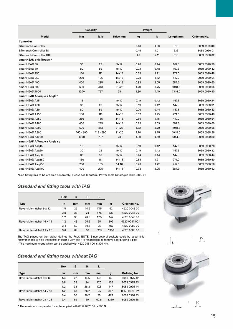
Model
Capacity
Drive mm
Weight
Length mm Ordering No.Nm ft.lb kg lb
Controller
STwrench Controller 0.48 1.08 313 8059 0930 00
STwrench Controller Bl 0.46 1.01 333 8059 0930 01
STwrench Controller HD 1.0 2.11 313 8059 0930 02
smartHEAD only Torque *
smartHEAD 30 30 23 9x12 0.20 0.44 167.5 8059 0920 30
smartHEAD 80 80 59 9x12 0.22 0.48 167.5 8059 0920 42
smartHEAD 150 150 111 14x18 0.55 1.21 271.0 8059 0920 48
smartHEAD 250 250 185 14x18 0.78 1.72 417.0 8059 0920 54
smartHEAD 400 400 295 14x18 0.93 2.05 584.0 8059 0920 60
smartHEAD 600 600 443 21x26 1.70 3.75 1048.5 8059 0920 66
smartHEAD 1000 1000 737 28 1.90 4.19 1344.0 8059 0920 80
smartHEAD A Torque + Angle*
smartHEAD A15 15 11 9x12 0.19 0.42 147.5 8059 0930 24
smartHEAD A30 30 23 9x12 0.19 0.42 147.5 8059 0930 31
smartHEAD A80 80 59 9x12 0.20 0.44 147.5 8059 0930 43
smartHEAD A150 150 111 14x18 0.57 1.25 271.0 8059 0930 48
smartHEAD A250 250 185 14x18 0.80 1.76 417.0 8059 0930 54
smartHEAD A400 400 295 14x18 0.95 2.09 584.0 8059 0930 60
smartHEAD A600 600 443 21x26 1.72 3.79 1048.5 8059 0930 66
smartHEAD A800 160 - 800 118 - 590 21x26 1.70 3.75 1048.5 8059 0988 26
smartHEAD A1000 1000 737 28 1.90 4.19 1344.0 8059 0930 80
smartHEAD A Torque + Angle sq
smartHEAD Asq15 15 11 9x12 0.19 0.42 147.5 8059 0930 28
smartHEAD Asq30 30 23 9x12 0.19 0.42 147.5 8059 0930 32
smartHEAD Asq80 80 59 9x12 0.44 0.44 147.5 8059 0930 44
smartHEAD Asq150 150 111 14x18 0.55 1.21 271.0 8059 0930 50
smartHEAD Asq250 250 185 14.18 0.78 1.72 417.0 8059 0930 56
smartHEAD Asq400 400 295 14x18 0.93 2.05 584.0 8059 0930 62
*End fitting has to be ordered separately, please see Industrial Power Tools Catalogue 9837 3000 01
Type
Hex B H L
g
Ordering No.in mm mm mm
Reversible ratchet 9 x 12 1/4 22 14.5 17.5 62 4620 0043 00
3/8 33 24 17.5 136 4620 0044 00
1/2 33 28.3 17.5 147 4620 0045 00
Reversible ratchet 14 x 18 1/2 43 26.2 25 302 4620 0081 00*
3/4 50 30.7 25 467 4620 0082 00
Reversible ratchet 21 x 26 3/4 69 30 62.5 1350 4620 0086 00
The TAG placed on the ratchet defines the Pset. NOTE: Since several sockets could be used, it is recommended to hold the socket in such a way that it is not possible to remove it (e.g. using a pin).* The maximum torque which can be applied with 4620 0081 00 is 300 Nm.
H
604 - 704
B
L
H
604 - 704
B
L
Standard end fitting tools with TAG
H
604 - 704
B
L
H
604 - 704
B
L
Type
Hex B H L
g Ordering No. in mm mm mm
Reversible ratchet 9 x 12 1/4 22 14.5 17.5 62 8059 0975 42
3/8 33 24 17.5 136 8059 0975 43
1/2 33 28.3 17.5 147 8059 0975 44
Reversible ratchet 14 x 18 1/2 43 26.2 25 302 8059 0976 32*
3/4 50 30.7 25 467 8059 0976 33
Reversible ratchet 21 x 26 3/4 69 30 62.5 1350 8059 0976 38
* The maximum torque which can be applied with 8059 0976 32 is 300 Nm.
Standard end fitting tools without TAG
16
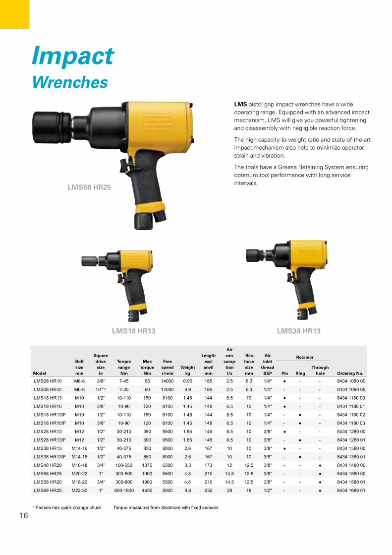
LMS58 HR25
LMS18 HR13
LMS pistol grip impact wrenches have a wide operating range. Equipped with an advanced impact mechanism, LMS will give you powerful tightening and disassembly with negligible reaction force.
The high capacity-to-weight ratio and state-of-the-art impact mechanism also help to minimize operator strain and vibration.
The tools have a Grease Retaining System ensuring optimum tool performance with long service intervals.
ImpactWrenches
LMS38 HR13
Model
Bolt size mm
Square drive size in
Torque range Nm
Max torque
Nm
Free speed r/min
Weight kg
Length excl anvil mm
Air con-
sump-tion l/s
Rec. hose size mm
Air inlet
thread BSP
Retainer
Ordering No.Pin RingThrough
hole
LMS08 HR10 M6-8 3/8'' 7-45 65 14000 0.90 185 2.5 6.3 1/4'' ● - - 8434 1080 00
LMS08 HR42 M6-8 1/4'' a 7-35 60 14000 0.9 186 2.5 6.3 1/4'' - - - 8434 1080 05
LMS18 HR13 M10 1/2'' 10-110 150 8100 1.45 144 8.5 10 1/4'' ● - - 8434 1180 00
LMS18 HR10 M10 3/8'' 10-90 120 8100 1.45 148 6.5 10 1/4'' ● - - 8434 1180 01
LMS18 HR13/F M10 1/2'' 10-110 150 8100 1.45 144 8.5 10 1/4'' - ● - 8434 1180 02
LMS18 HR10/F M10 3/8'' 10-90 120 8100 1.45 148 6.5 10 1/4'' - ● - 8434 1180 03
LMS28 HR13 M12 1/2'' 30-210 390 9500 1.85 146 8.5 10 3/8'' ● - - 8434 1280 00
LMS28 HR13/F M12 1/2'' 30-210 390 9500 1.85 146 8.5 10 3/8'' - ● - 8434 1280 01
LMS38 HR13 M14-16 1/2'' 40-375 850 8000 2.6 167 10 10 3/8'' ● - - 8434 1380 00
LMS38 HR13/F M14-16 1/2'' 40-375 850 8000 2.6 167 10 10 3/8'' - ● - 8434 1380 01
LMS48 HR20 M16-18 3/4'' 100-550 1375 6500 3.3 173 12 12.5 3/8'' - - ● 8434 1480 00
LMS58 HR25 M20-22 1'' 300-800 1900 5500 4.8 210 14.5 12.5 3/8'' - - ● 8434 1580 00
LMS58 HR20 M18-20 3/4'' 300-800 1900 5500 4.8 210 14.5 12.5 3/8'' - - ● 8434 1580 01
LMS68 HR25 M22-30 1'' 600-1800 4450 5000 9.8 252 28 16 1/2'' - - ● 8434 1680 01
a Female hex quick change chuck Torque measured from Skidmore with fixed sensors
17
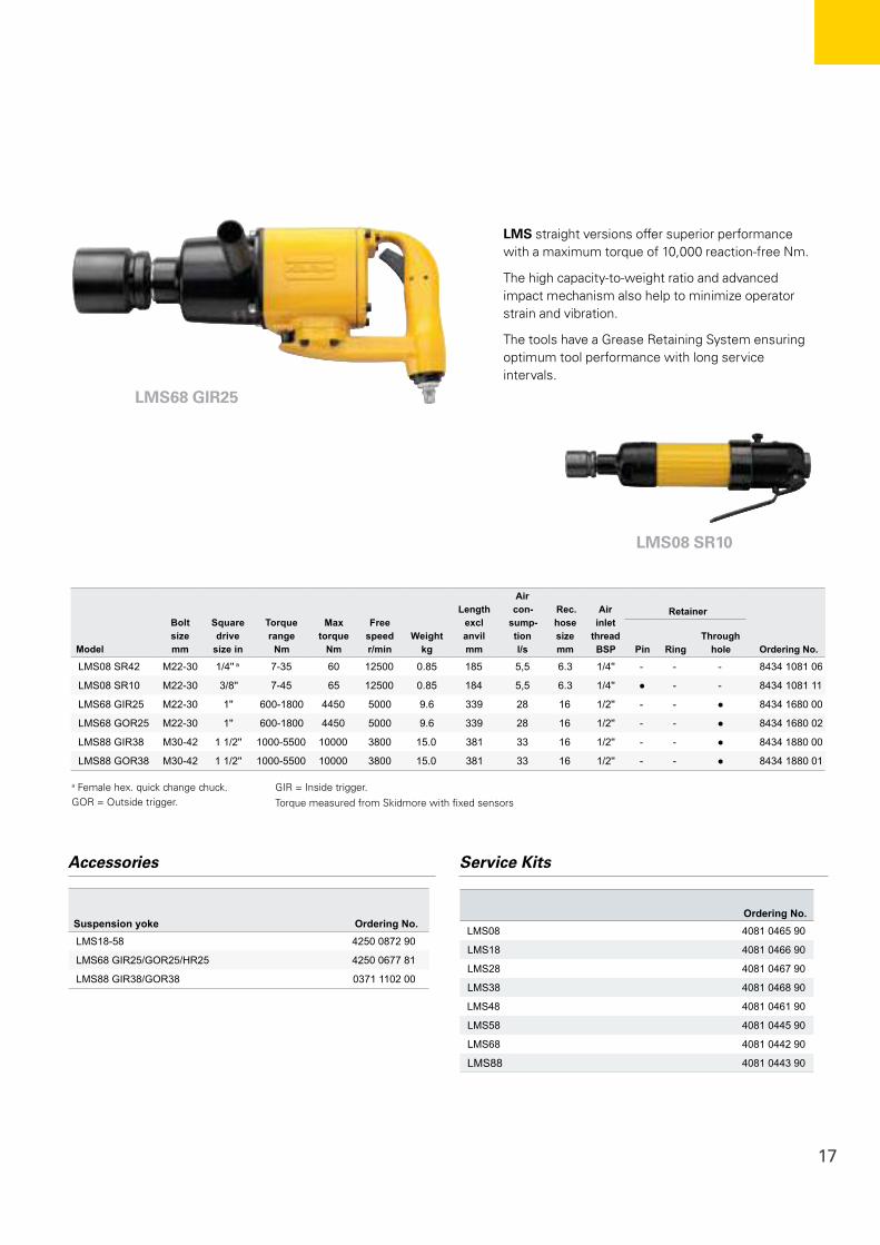
ImpactWrenches
LMS08 SR10
LMS68 GIR25
LMS straight versions offer superior performance with a maximum torque of 10,000 reaction-free Nm.
The high capacity-to-weight ratio and advanced impact mechanism also help to minimize operator strain and vibration.
The tools have a Grease Retaining System ensuring optimum tool performance with long service intervals.
Model
Bolt size mm
Square drive
size in
Torque range
Nm
Max torque
Nm
Free speed r/min
Weight kg
Length excl anvil mm
Air con-
sump-tion l/s
Rec. hose size mm
Air inlet
thread BSP
Retainer
Ordering No.Pin RingThrough
hole
LMS08 SR42 M22-30 1/4'' a 7-35 60 12500 0.85 185 5,5 6.3 1/4'' - - - 8434 1081 06
LMS08 SR10 M22-30 3/8'' 7-45 65 12500 0.85 184 5,5 6.3 1/4'' ● - - 8434 1081 11
LMS68 GIR25 M22-30 1'' 600-1800 4450 5000 9.6 339 28 16 1/2'' - - ● 8434 1680 00
LMS68 GOR25 M22-30 1'' 600-1800 4450 5000 9.6 339 28 16 1/2'' - - ● 8434 1680 02
LMS88 GIR38 M30-42 1 1/2'' 1000-5500 10000 3800 15.0 381 33 16 1/2'' - - ● 8434 1880 00
LMS88 GOR38 M30-42 1 1/2'' 1000-5500 10000 3800 15.0 381 33 16 1/2'' - - ● 8434 1880 01
Accessories
Suspension yoke Ordering No.LMS18-58 4250 0872 90
LMS68 GIR25/GOR25/HR25 4250 0677 81
LMS88 GIR38/GOR38 0371 1102 00
Service Kits
Ordering No.LMS08 4081 0465 90
LMS18 4081 0466 90
LMS28 4081 0467 90
LMS38 4081 0468 90
LMS48 4081 0461 90
LMS58 4081 0445 90
LMS68 4081 0442 90
LMS88 4081 0443 90
a Female hex. quick change chuck. GOR = Outside trigger.
GIR = Inside trigger.Torque measured from Skidmore with fixed sensors
18
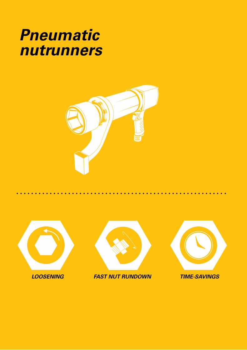
LOOSENING FAST NUT RUNDOWN TIME-SAVINGS
Pneumatic nutrunners

19
20
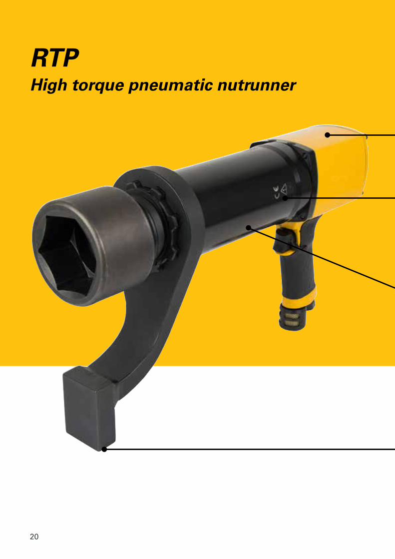
RTPHigh torque pneumatic nutrunner

21
Swiveling gear packThe light weight of the RTP nutrunner will surprise you, yet its high speed motor has
the power you need to tighten big bolts.
Fast and accurateWell proven Atlas Copco air motor.
Reaction BarsAbsorbs reaction force. Different bars
are available.
Excellent accessibility, high accuracy Among the smallest on the market, the RTP’s
slim gearpack gives you effortless access to bolts in cramped spaces. Tightening accuracy and
repeatability are high.
Whatever your industry, if your operations include loosening or tightening heavy duty bolts, Atlas Copco’s slim, lightweight RTP pneumatic nutrunner can help increase your productivity.
22
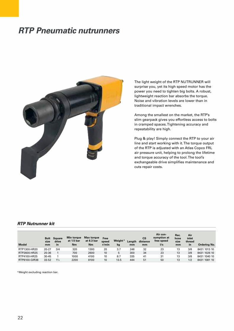
The light weight of the RTP NUTRUNNER will surprise you, yet its high speed motor has the power you need to tighten big bolts. A robust, lightweight reaction bar absorbs the torque. Noise and vibration levels are lower than in traditional impact wrenches.
Among the smallest on the market, the RTP’s slim gearpack gives you effortless access to bolts in cramped spaces. Tightening accuracy and repeatability are high.
Plug & play! Simply connect the RTP to your air line and start working with it. The torque output of the RTP is adjusted with an Atlas Copco FRL air pressure unit, helping to prolong the lifetime and torque accuracy of the tool. The tool’s exchangeable drive simplifies maintenance and cuts repair costs.
RTP Nutrunner kit
Air con- Rec. Air Bolt Square Min torque Max torque Free CS sumption at hose inlet size drive at 1.5 bar at 6.3 bar speed Weight a
Length distance free speed size thread Model mm in Nm Nm r/min kg mm mm l/s mm in Ordering No.
RTP1300-HR20 20-27 3/4 320 1300 20 3.7 248 32 23 13 3/8 8431 1013 10RTP2600-HR25 20-36 1 700 2600 10 5 300 34 23 13 3/8 8431 1026 10RTP4100-HR25 30-45 1 1000 4100 10 8.7 335 41 31 13 3/8 8431 1040 10RTP8100-GIR38 33-52 11/2 2200 8100 10 13.5 444 51 50 13 1/2 8431 1081 10
a Weight excluding reaction bar.
RTP Pneumatic nutrunners
23
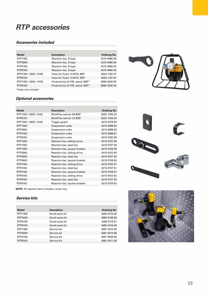
RTP accessories
Model Description Ordering No.
RTP1300 Small parts kit 4082 0125 90
RTP2600 Small parts kit 4082 0148 90
RTP4100 Small parts kit 4082 0116 91
RTP8100 Small parts kit 4082 0126 90
RTP1300 Service kit 4081 0510 90
RTP2600 Service kit 4081 0510 90
RTP4100 Service kit 4081 0504 90
RTP8100 Service kit 4081 0511 90
Service kits
Model Description Ordering No.
RTP1300 Reaction bar, S-type 4210 4480 90
RTP2600 Reaction bar, S-type 4210 4480 94
RTP4100 Reaction bar, S-type 4210 4480 93
RTP8100 Reaction bar, S-type 4210 4480 92
RTP1300 / 2600 / 4100 Hose kit, Turbo 13 M10, BSP 8202 1182 07
RTP8100 Hose kit, Turbo 13 M15, BSP 8202 1181 81
RTP1300 / 2600 / 4100 Productivity kit FRL stand, BSP b 9090 3030 06
RTP8100 Productivity kit FRL stand, BSP b 9090 3030 04b Hose not included
Accessories included
Model Description Ordering No.
RTP1300 / 2600 / 4100 MultiFlex swivel 3/8 BSP 8202 1350 22
RTP8100 MultiFlex swivel 1/2 BSP 8202 1350 24
RTP1300 / 2600 / 4100 Trigger guard 4210 4759 90
RTP1300 Suspension yoke 4210 3088 83
RTP2600 Suspension yoke 4210 3088 82
RTP4100 Suspension yoke 4210 3088 81
RTP8100 Suspension yoke 4210 4780 90
RTP1300 Reaction bar, sliding-drive 4210 4752 90
RTP1300 Reaction bar, steel bar 4210 4757 90
RTP1300 Reaction bar, square bracket 4210 4758 90
RTP2600 Reaction bar, sliding-drive 4210 4752 93
RTP2600 Reaction bar, steel bar 4210 4757 93
RTP2600 Reaction bar, square bracket 4210 4758 93
RTP4100 Reaction bar, sliding-drive 4210 4752 91
RTP4100 Reaction bar, steel bar 4210 4757 91
RTP4100 Reaction bar, square bracket 4210 4758 91
RTP8100 Reaction bar, sliding-drive 4210 4752 92
RTP8100 Reaction bar, steel bar 4210 4757 92
RTP8100 Reaction bar, square bracket 4210 4758 92
NOTE: All reaction bars includes a snap ring
Optional accessories

24
LTP and LMPPneumatic nutrunner

25
With the Atlas Copco LMP/LTP61 range of twin-motor pistol grip nutrunners you get the highest possible torque and speed in relation to the weight of the tool. Fast, accurate and highly user-friendly, the tools are available in reversible versions for maximum flexibility.
Reversible for maximum flexibilityBeing able to loosen fasteners without
changing tools saves time and effort and raises productivity.
Fast and accurateIn LTP/LMP61 tools the twin motor concept
provides extremely fast rundown with good torque accuracy, even on soft joints.
Operator friendlyOur pistol grip nutrunners are comfortable to operate. The reaction bar eliminates reaction
forces and the exhaust through the handle arrangement keeps noise levels low.
26
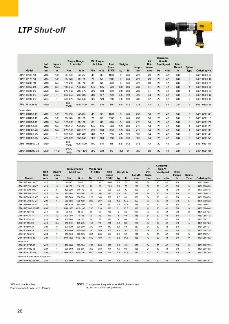
LTP Shut-off
Model
BoltSizemm
SquareDrive
In
Torque RangeAt 6.3 Bar
Min TorqueAt 3 Bar Free
SpeedR/Min
Weight a
Lengthmm
CsDis-
tancemm
Consump-tion At
Free Speed InletThread
InSplineType Ordering No.Nm ft lb Nm ft lb kg lb l/s cfm
LTP61 H100-13 M12 1/2 55-100 40-75 45 35 1800 3 6.6 223 29 20 42 3/8 3 8431 0800 07
LTP61 H170-13 M14 1/2 95-170 70-125 70 50 1100 3 6.6 223 29 20 42 3/8 3 8431 0800 14
LTP61 H230-19 M16 3/4 125-230 90-170 85 60 820 3 6.6 223 29 20 42 3/8 3 8431 0800 21
LTP61 H350-20 M18 3/4 190-350 140-255 145 105 520 3.9 8.6 260 31 20 42 3/8 4 8431 0800 28
LTP61 H500-20 M20 3/4 275-500 200-370 220 160 360 3.9 8.6 260 31 20 42 3/8 4 8431 0800 35
LTP61 H700-25 M22 1 360-650 265-480 280 207 280 4.5 9.9 305 34 20 42 3/8 5 8431 0800 42
LTP61 H900-25 M24 1 480-870 350-640 300 220 210 4.5 9.9 282 32 20 42 3/8 5 8431 0800 49
LTP61 H1500-25 M30 1850-1500
625-1100 700 516 115 6.8 14.5 323 42 20 42 3/8 9 8431 0800 56
Reversible
LTP61 HR100-13 M12 1/2 55-100 40-75 45 35 1800 3 6.6 235 30 20 42 3/8 3 8431 0801 08
LTP61 HR170-13 M14 1/2 95-170 70-125 70 50 1100 3 6.6 238 30 20 42 3/8 3 8431 0801 15
LTP61 HR230-19 M16 3/4 125-230 90-170 85 60 820 3 6.6 275 34 20 42 3/8 3 8431 0801 22
LTP61 HR350-20 M18 3/4 190-350 140-255 145 105 520 3.9 8.6 275 34 20 42 3/8 4 8431 0801 29
LTP61 HR500-20 M20 3/4 275-500 200-370 220 160 360 3.9 8.6 275 34 20 42 3/8 4 8431 0801 36
LTP61 HR700-25 M22 1 360-650 265-480 280 207 280 4.5 9.9 305 34 20 42 3/8 5 8431 0801 43
LTP61 HR900-25 M24 1 480-870 350-640 300 220 210 4.5 9.9 305 34 20 42 3/8 5 8431 0801 50
LTP61 HR1500-25 M30 1850-1500
625-1100 700 516 115 6.8 14.5 345 42 20 42 3/8 9 8431 0801 57
LTP61 HR1900-38 M30 1 1/21050-1900
770-1400 800 590 90 14.1 31 380 68 20 42 3/8 8 8431 0801 64
Model
BoltSizemm
SquareDrive
In
Torque RangeAt 6.3 Bar
Min TorqueAt 3 Bar Free
SpeedR/Min
Weight ALength
mm
CsDis-
tancemm
Consump-tion At
Free Speed InletThread
InSplineType Ordering No.Nm ft lb Nm ft lb kg lb l/s cfm
LTP61 HR100-13-MT M12 1/2 55-100 40-75 45 35 1800 3.3 7.3 288 30 20 42 3/8 3 8431 0806 02
LTP61 HR170-13-MT M14 1/2 95-170 70-125 70 50 1100 3.3 7.3 288 30 20 42 3/8 3 8431 0806 09
LTP61 HR230-19-MT M16 3/4 125-230 90-170 85 60 820 3.3 7.3 288 34 20 42 3/8 3 8431 0806 16
LTP61 HR350-20-MT M18 3/4 190-350 140-255 145 105 520 4.2 9.2 325 34 20 42 3/8 4 8431 0806 23
LTP61 HR500-20-MT M20 3/4 275-500 200-370 220 160 360 4.2 9.2 325 34 20 42 3/8 4 8431 0806 30
LTP61 HR700-25-MT M22 1 360-650 265-480 280 207 280 4.8 10.6 355 34 20 42 3/8 5 8431 0806 33
LTP61 HR900-25-MT M24 1 480-870 350-640 300 220 210 4.8 10.6 355 34 20 42 3/8 5 8431 0806 37
LTP61 HR1500-25-MT M30 1 850-1500 625-1100 700 516 115 7.1 15.6 395 42 20 42 3/8 9 8431 0806 44
LTP61 PH100-13 M12 1/2 60-110 45-80 45 33 700 3 6.6 223 34 20 42 3/8 3 8431 0807 04
LTP61 PH170-13 M14 1/2 100-180 75-135 70 52 440 3 6.6 223 34 20 42 3/8 3 8431 0807 12
LTP61 PH230-19 M16 3/4 130-240 95-180 90 66 320 3 6.6 223 34 20 42 3/8 3 8431 0807 17
LTP61 PH350-20 M18 3/4 210-370 155-275 150 110 200 3.9 8.6 260 34 20 42 3/8 4 8431 0807 24
LTP61 PH500-20 M20 3/4 300-520 220-380 200 150 140 3.9 8.6 260 34 20 42 3/8 4 8431 0807 31
LTP61 PH700-25 M22 1 400-680 295-500 280 205 100 4.5 9.9 305 34 20 42 3/8 5 8431 0807 38
LTP61 PH900-25 M24 1 500-900 370-665 350 260 80 4.5 9.9 282 34 20 42 3/8 5 8431 0807 41
LTP61 PH1500-25 M30 1 900-1600 665-1180 650 480 45 6.8 14.9 323 42 20 42 3/8 9 8431 0807 52
Reversible
LTP61 PHR700-25 M22 1 400-680 295-500 280 205 100 4.5 9.9 305 34 20 42 3/8 5 8431 0807 55
LTP61 PHR900-25 M24 1 500-900 370-665 350 260 80 4.5 9.9 305 34 20 42 3/8 5 8431 0807 62
LTP61 PHR1500-25 M30 1 900-1600 665-1180 650 480 45 6.8 14.9 345 42 20 42 3/8 9 8431 0807 68
Reversible with Multi Torque unit
LTP61 PHR900-25-MT M24 1 500-900 370-665 350 260 80 4.8 10.6 305 34 20 42 3/8 5 8431 0807 81
27
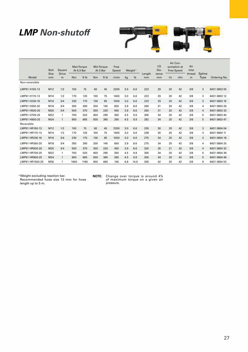
LMP Non-shutoff
Model
BoltSizemm
SquareDrive
in
Max TorqueAt 6.3 Bar
Min TorqueAt 3 Bar
FreeSpeed Weight a
Lengthmm
CS Dis-
tancemm
Air Con-sumption at Free Speed
Air inlet
thread in
SplineType Ordering No.Nm ft lb Nm ft lb r/min kg lb l/s cfm
Non-reversible
LMP61 H100-13 M12 1/2 100 75 60 45 2200 3.0 6.6 223 29 20 42 3/8 3 8431 0803 05
LMP61 H170-13 M14 1/2 170 125 100 75 1400 3.0 6.6 223 29 20 42 3/8 3 8431 0803 12
LMP61 H230-19 M16 3/4 230 170 130 95 1000 3.0 6.6 223 29 20 42 3/8 3 8431 0803 19
LMP61 H350-20 M18 3/4 350 260 200 145 650 3.9 8.6 260 31 20 42 3/8 4 8431 0803 26
LMP61 H500-20 M20 3/4 500 370 300 220 450 3.9 8.6 260 31 20 42 3/8 4 8431 0803 33
LMP61 H700-25 M22 1 700 520 400 295 350 4.5 9.9 305 34 20 42 3/8 5 8431 0803 40
LMP61 H900-25 M24 1 900 665 500 365 260 4.5 9.9 282 34 20 42 3/8 5 8431 0803 47
Reversible
LMP61 HR100-13 M12 1/2 100 75 60 45 2200 3.0 6.6 235 30 20 42 3/8 3 8431 0804 04
LMP61 HR170-13 M14 1/2 170 125 100 75 1400 3.0 6.6 238 30 20 42 3/8 3 8431 0804 11
LMP61 HR230-19 M16 3/4 230 170 130 95 1000 3.0 6.6 275 34 20 42 3/8 3 8431 0804 18
LMP61 HR350-20 M18 3/4 350 260 200 145 650 3.9 8.6 275 34 20 42 3/8 4 8431 0804 25
LMP61 HR500-20 M20 3/4 500 370 300 220 450 3.9 8.6 320 35 21 42 3/8 4 8431 0804 32
LMP61 HR700-25 M22 1 700 520 400 295 350 4.5 9.9 305 34 20 42 3/8 5 8431 0804 39
LMP61 HR900-25 M24 1 900 665 500 365 260 4.5 9.9 305 34 20 42 3/8 5 8431 0804 46
LMP61 HR1500-25 M30 1 1600 1180 900 660 140 6.8 14.9 345 42 20 42 3/8 9 8431 0804 53
a Weight excluding reaction bar.Recommended hose size 13 mm for hose length up to 5 m.
NOTE: Change over torque is around 4% of maximum torque on a given air pressure.
28
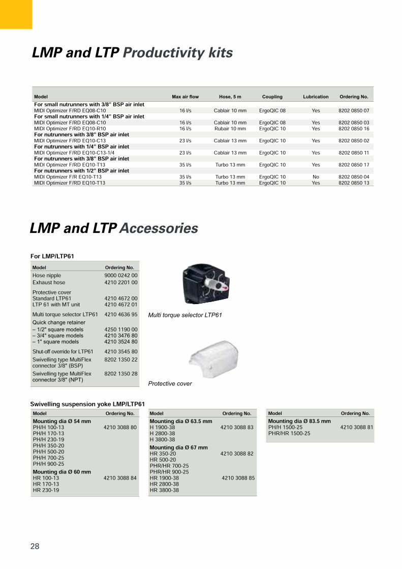
LMP and LTP Productivity kits
LMP and LTP Accessories
29
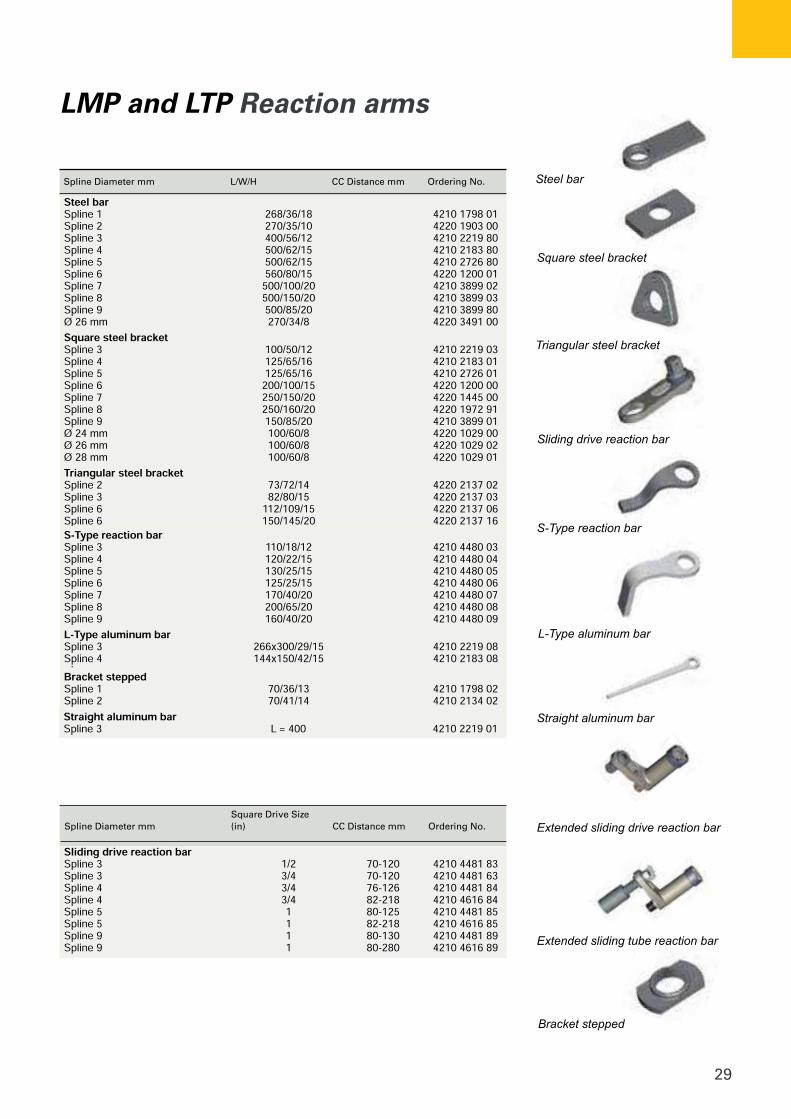
Spline Diameter mm L/W/H CC Distance mm Ordering No.
Spline Diameter mmSquare Drive Size (in) CC Distance mm Ordering No.
LMP and LTP Reaction arms
30
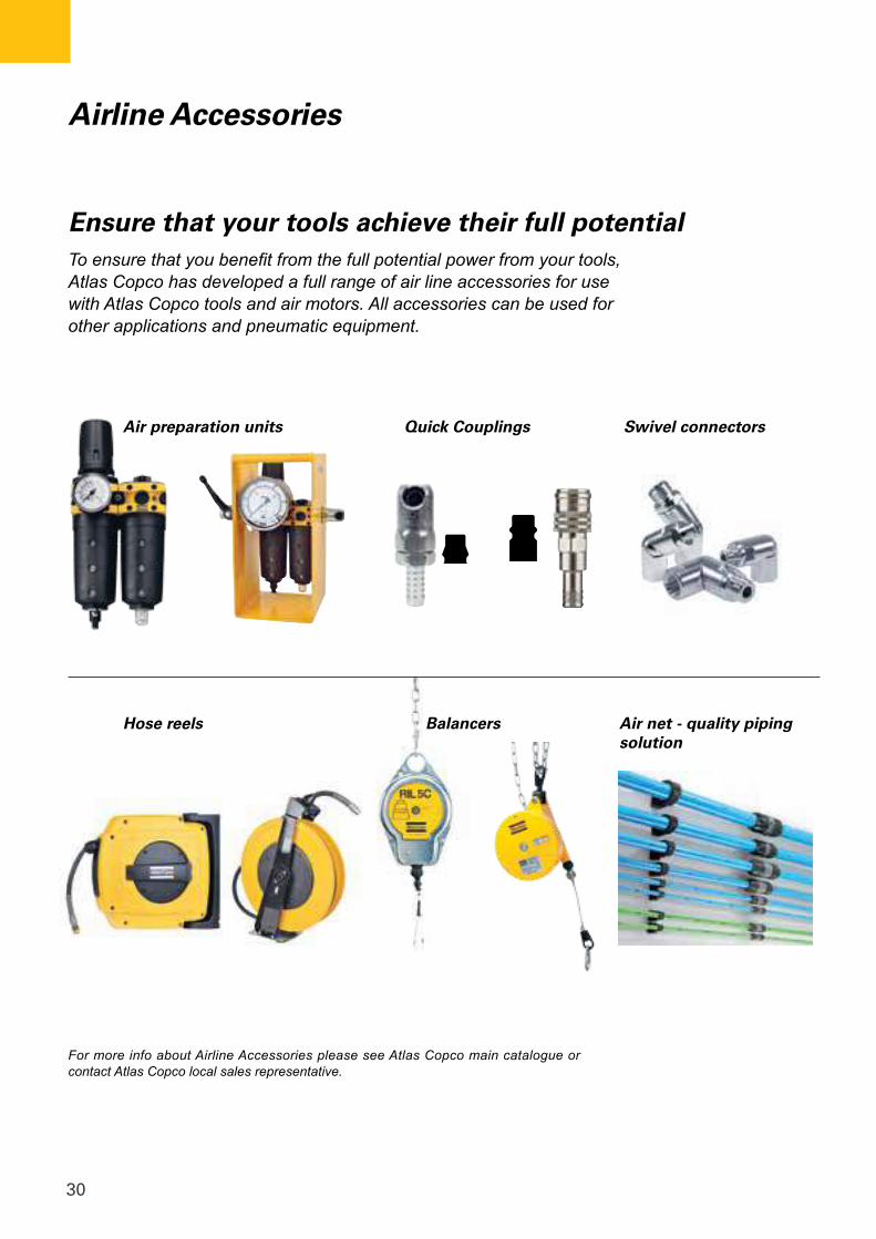
Air preparation units
Hose reels Balancers Air net - quality piping solution
Quick Couplings Swivel connectors
For more info about Airline Accessories please see Atlas Copco main catalogue or contact Atlas Copco local sales representative.
Airline Accessories
To ensure that you benefit from the full potential power from your tools, Atlas Copco has developed a full range of air line accessories for use with Atlas Copco tools and air motors. All accessories can be used for other applications and pneumatic equipment.
Ensure that your tools achieve their full potential
31
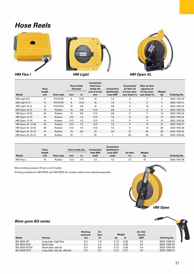
Model
Hose length
mm Hose type
Hose inside diameter
Connection inlet hose inside dia
(cut of hose) mm
Connection distribution hose BSP
Economical air flow (at
0.2 bar) pres-sure drop) l/s
Max air flow capacity (at 0.5 bar pres-sure drop) l/s
Weight kg Ordering No. mm in
HM Light 8-8 8 PVC/PUR 8 5/16 10 1/4 4 7 3 8202 1183 30
HM Light 8-12 12 PVC/PUR 8 5/16 10 1/4 3 5 5 8202 1183 31
HM Light 10-10 10 PVC/PUR 10 3/8 10 3/8 6 10 5 8202 1183 32
HM Open 10-15 15 Rubber 10 3/8 12.5 3/8 5 9 11 8202 1183 33
HM Open 10-20 20 Rubber 10 3/8 12.5 3/8 5 7 14 8202 1183 34
HM Open 12-10 10 Rubber 12.5 1/2 12.5 1/2 13 22 12 8202 1183 35
HM Open 12-15 10 Rubber 12.5 1/2 12.5 1/2 11 17 13 8202 1183 36
HM Open XL 12-20 20 Rubber 12.5 1/2 12.5 1/2 8 14 27 8202 1183 37
HM Open XL 12-20 30 Rubber 12.5 1/2 12.5 1/2 8 12 28 8202 1183 38
HM Open XL 19-15 15 Rubber 19 3/4 19 3/4 27 44 28 8202 1183 39
HM Open XL 25-10 10 Rubber 25 1 25 1 60 95 30 8202 1183 40
Model
Hose length
mm Hose type
Hose inside dia Connection inlet BSP
male
Connection distribution hose BSP
maleAir flow
l/sWeight
kg Ordering No. mm in
HM Flex L 10 Rubber 12,5 1/2 1/2 1/2 22 16 8202 1181 56
Hose Reels
Max working pressure 15 bar on all models.
Pivoting brackets for HM OPEN and HM OPEN XL models needs to be ordered separately
HM Open
HM Flex l HM Light HM Open XL
Blow guns BG-series
Working Air Air inlet pressure flow Weight thread Model Version bar l/s kg lb BSP Ordering No.BG 2603-HF Long tube, high flow 6.3 7.5 0.13 0.29 1/4 8202 1006 04BG 2604-SHF Short tube 6.3 4.3 0.12 0.26 1/4 8202 1006 05BG 2605-STSS Short tube, star tip 6.3 6.6 0.12 0.26 1/4 8202 1006 06BG 2606-STS Long tube, star tip, silencer 6.3 6.3 0.14 0.31 1/4 8202 1006 07
32
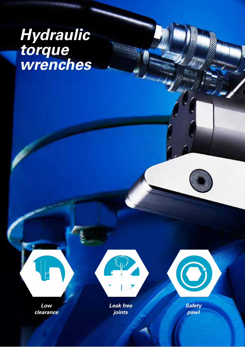
Hydraulictorquewrenches
Low clearance
Leak freejoints
Safetypawl

33

34
RT SeriesSquare drivehydraulic torque wrench
35
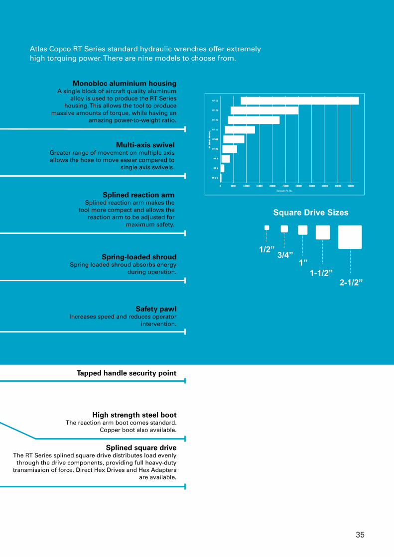
Square Drive Sizes
2-1/2”
1/2” 1”
1-1/2”
3/4”
Tapped handle security point
Torque Ft. lb.
Splined square driveThe RT Series splined square drive distributes load evenly
through the drive components, providing full heavy-duty transmission of force. Direct Hex Drives and Hex Adapters
are available.
Spring-loaded shroudSpring loaded shroud absorbs energy
during operation.
Safety pawl Increases speed and reduces operator
intervention.
High strength steel bootThe reaction arm boot comes standard.
Copper boot also available.
Multi-axis swivel Greater range of movement on multiple axis allows the hose to move easier compared to
single axis swivels.
Splined reaction armSplined reaction arm makes the
tool more compact and allows the reaction arm to be adjusted for
maximum safety.
Atlas Copco RT Series standard hydraulic wrenches offer extremely high torquing power. There are nine models to choose from.
Monobloc aluminium housingA single block of aircraft quality aluminum
alloy is used to produce the RT Series housing. This allows the tool to produce
massive amounts of torque, while having an amazing power-to-weight ratio.
36
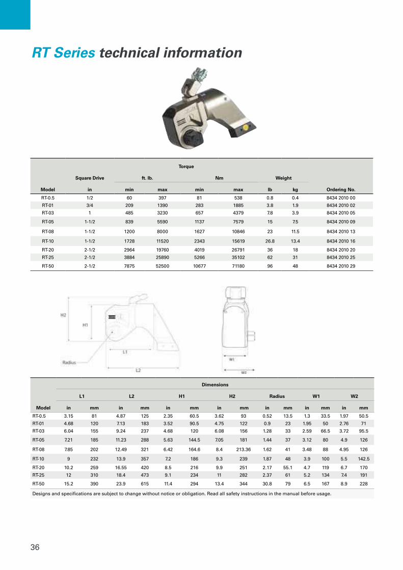
Model
Dimensions
L1 L2 H1 H2 Radius W1 W2
in mm in mm in mm in mm in mm in mm in mm
RT-0.5 3.15 81 4.87 125 2.35 60.5 3.62 93 0.52 13.5 1.3 33.5 1.97 50.5
RT-01 4.68 120 7.13 183 3.52 90.5 4.75 122 0.9 23 1.95 50 2.76 71
RT-03 6.04 155 9.24 237 4.68 120 6.08 156 1.28 33 2.59 66.5 3.72 95.5
RT-05 7.21 185 11.23 288 5.63 144.5 7.05 181 1.44 37 3.12 80 4.9 126
RT-08 7.85 202 12.49 321 6.42 164.6 8.4 213.36 1.62 41 3.48 88 4.95 126
RT-10 9 232 13.9 357 7.2 186 9.3 239 1.87 48 3.9 100 5.5 142.5
RT-20 10.2 259 16.55 420 8.5 216 9.9 251 2.17 55.1 4.7 119 6.7 170
RT-25 12 310 18.4 473 9.1 234 11 282 2.37 61 5.2 134 7.4 191
RT-50 15.2 390 23.9 615 11.4 294 13.4 344 30.8 79 6.5 167 8.9 228
Designs and specifications are subject to change without notice or obligation. Read all safety instructions in the manual before usage.
Model
Square Drive
Torque
Weight
Ordering No.
ft. lb. Nm
in min max min max lb kg
RT-0.5 1/2 60 397 81 538 0.8 0.4 8434 2010 00
RT-01 3/4 209 1390 283 1885 3.8 1.9 8434 2010 02
RT-03 1 485 3230 657 4379 7.8 3.9 8434 2010 05
RT-05 1-1/2 839 5590 1137 7579 15 7.5 8434 2010 09
RT-08 1-1/2 1200 8000 1627 10846 23 11.5 8434 2010 13
RT-10 1-1/2 1728 11520 2343 15619 26.8 13.4 8434 2010 16
RT-20 2-1/2 2964 19760 4019 26791 36 18 8434 2010 20
RT-25 2-1/2 3884 25890 5266 35102 62 31 8434 2010 25
RT-50 2-1/2 7875 52500 10677 71180 96 48 8434 2010 29
RT Series technical information
37
1
2
1
2
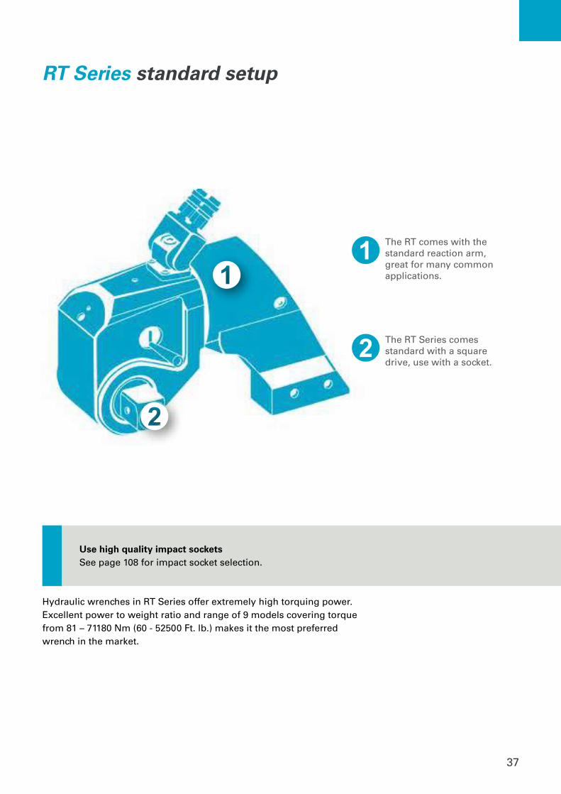
The RT comes with the standard reaction arm, great for many common applications.
The RT Series comes standard with a square drive, use with a socket.
RT Series standard setup
Use high quality impact socketsSee page 108 for impact socket selection.
Hydraulic wrenches in RT Series offer extremely high torquing power. Excellent power to weight ratio and range of 9 models covering torque from 81 – 71180 Nm (60 - 52500 Ft. lb.) makes it the most preferred wrench in the market.
38
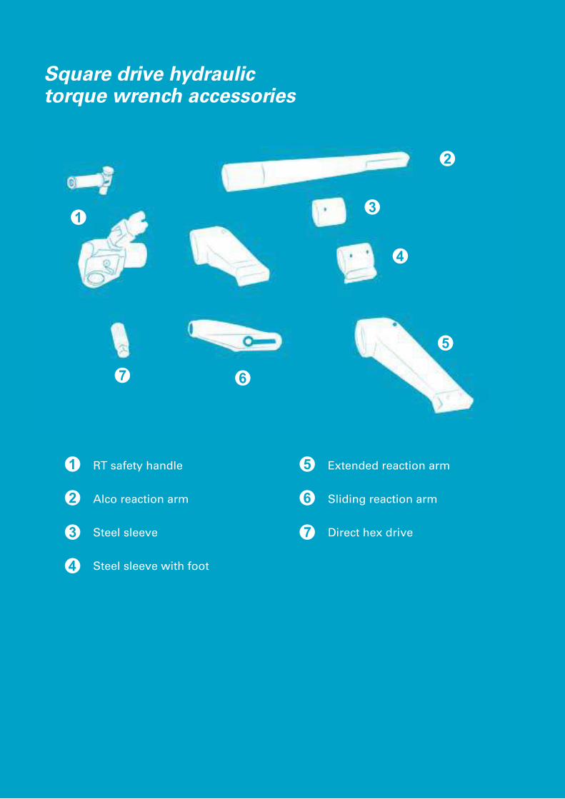
RT safety handle
Alco reaction arm
Steel sleeve
Steel sleeve with foot
Extended reaction arm
Sliding reaction arm
Direct hex drive
Square drive hydraulic torque wrench accessories
39
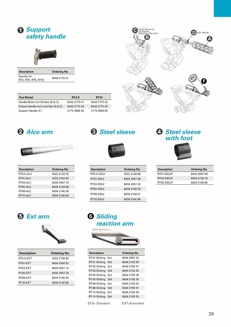
Supportsafety handle
Description Ordering No.
Handle forRT3, RT5, RT8, RT10
8434 2170 31
Description Ordering No.
RT0.5-ALC 4222 2126 76
RT01-ALC 4222 2102 64
RT03-ALC 8434 2057 10
RT05-ALC 8434 2139 88
RT08-ALC 8434 2140 36
RT10-ALC 8434 2140 60
Description Ordering No.
RT0.5-SSLV 4222 2126 88
RT01-SSLV 8434 2057 08
RT03-SSLV 8434 2057 32
RT05-SSLV 8434 2140 30
RT08-SSLV 8434 2140 51
RT10-SSLV 8434 2140 90
Alco arm Steel sleeve Steel sleevewith foot
Description Ordering No.
RT01-SSLVF 8434 2057 09
RT03-SSLVF 8434 2139 79
RT05-SSLVF 8434 2139 80
Ext arm Slidingreaction arm
STD= Standard EXT=Extended
Description Ordering No.
RT0.5-EXT 4222 2126 82
RT01-EXT 8434 2056 92
RT03-EXT 8434 2057 12
RT05-EXT 8434 2057 34
RT08-EXT 8434 2140 42
RT10-EXT 8434 2140 66
Description Ordering No.
RT-01 Sliding Ext 8434 2057 33
RT-01 Sliding Std 8434 2150 95
RT-03 Sliding Ext 8434 2150 37
RT-03 Sliding Std 8434 2150 30
RT-05 Sliding Ext 8434 2150 36
RT-05 Sliding Std 8434 2150 35
RT-08 Sliding Ext 8434 2150 32
RT-08 Sliding Std 8434 2150 31
RT-10 Sliding Ext 8434 2150 34
RT-10 Sliding Std 8434 2150 33
Tool Model RT-0.5 RT-01
Handle Block Incl Screws (B & C) 8434 2170 41 8434 2170 42Fixture Handle Incl Lock Nut (A & D) 8434 2170 43 8434 2170 43Support Handle (F) 4175 0868 80 4175 0868 80
BC
AD
F

40
Direct hex drive
RT Series accessories
Ordering No Size Description
8434 2101 72 1/2" RT0.5-HX-008
8434 2138 44 10mm RT0.5-HX-10MM
8434 2138 47 12mm RT0.5-HX-12MM
8434 2138 50 14mm RT0.5-HX-14MM
8434 2138 53 16mm RT0.5-HX-16MM
8434 2138 56 17mm RT0.5-HX-17MM
8434 2138 59 18mm RT0.5-HX-18MM
8434 2138 62 19mm RT0.5-HX-19MM
8434 2138 65 20mm RT0.5-HX-20MM
8434 2138 68 22mm RT0.5-HX-22MM
8434 2101 71 24mm RT0.5-HX-24MM
8434 2138 71 5/8" RT01-HX-010
8434 2138 74 3/4" RT01-HX-012
8434 2138 77 7/8" RT01-HX-014
8434 2056 94 1" RT01-HX-100
8434 2138 83 10mm RT01-HX-10MM
8434 2138 86 14mm RT01-HX-14MM
8434 2138 89 16mm RT01-HX-16MM
8434 2056 96 17mm RT01-HX-17MM
8434 2138 92 18mm RT01-HX-18MM
8434 2056 98 19mm RT01-HX-19MM
8434 2057 00 20mm RT01-HX-20MM
8434 2057 02 22mm RT01-HX-22MM
8434 2057 04 24mm RT01-HX-24MM
8434 2138 98 25mm RT01-HX-25MM
8434 2138 95 26mm RT01-HX-26MM
8434 2057 06 27mm RT01-HX-27MM
8434 2057 14 5/8" RT03-HX-010
8434 2057 16 3/4" RT03-HX-012
8434 2057 18 7/8" RT03-HX-014
8434 2057 20 1" RT03-HX-100
8434 2139 28 1 1/8" RT03-HX-102
8434 2139 31 1 1/4" RT03-HX-104
8434 2139 34 1 1/2" RT03-HX-108
8434 2139 35 15mm RT03-HX-15MM
8434 2139 36 16mm RT03-HX-16MM
8434 2139 37 17mm RT03-HX-17MM
8434 2057 22 19mm RT03-HX-19MM
8434 2057 24 22mm RT03-HX-22MM
8434 2057 26 24mm RT03-HX-24MM
8434 2139 43 26mm RT03-HX-26MM
8434 2057 28 27mm RT03-HX-27MM
8434 2139 46 30mm RT03-HX-30MM
8434 2057 30 32mm RT03-HX-32MM
8434 2139 49 36mm RT03-HX-36MM
8434 2139 55 38mm RT03-HX-38MM
Ordering No Size Description
8434 2139 58 41mm RT03-HX-41MM
8434 2139 61 46mm RT03-HX-46MM
8434 2139 64 55mm RT03-HX-55MM
8434 2140 04 1" RT-05
8434 2140 13 1 1/4" RT05-HX-104
8434 2139 97 19mm RT05-HX-19MM
8434 2140 00 22mm RT05-HX-22MM
8434 2140 03 24mm RT05-HX-24MM
8434 2140 06 26mm RT05-HX-26MM
8434 2057 36 27mm RT05-HX-27MM
8434 2140 10 30mm RT05-HX-30MM
8434 2140 12 32mm RT05-HX-32MM
8434 2057 38 36mm RT05-HX-36MM
8434 2057 39 38mm RT05-HX-38
8434 2057 40 41mm RT05-HX-41MM
8434 2057 42 46mm RT05-HX-46MM
8434 2140 20 50mm RT05-HX-50MM
8434 2140 21 55mm RT05-HX-55MM
8434 2140 45 24mm RT08-HX-24MM
8434 2140 48 27mm RT08-HX-27MM
8434 2140 69 1" RT10-HX-100
8434 2140 72 1 1/2" RT10-HX-108
8434 2140 75 32mm RT10-HX-32MM
8434 2057 46 36mm RT10-HX-36MM
8434 2057 48 41mm RT10-HX-41MM
8434 2057 50 46mm RT10-HX-46MM
8434 2057 52 50mm RT10-HX-50MM
8434 2140 81 55mm RT10-HX-55MM
41
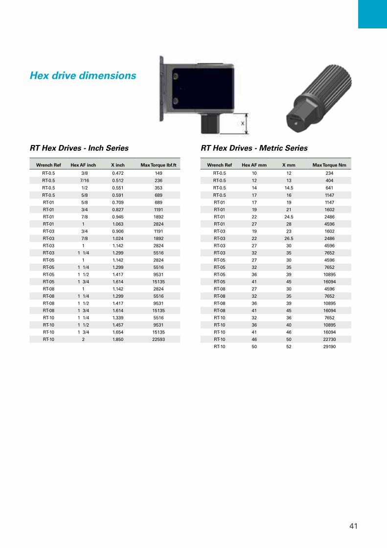
Hex drive dimensions
Wrench Ref Hex AF inch X inch Max Torque lbf.ft
RT-0.5 3/8 0.472 149
RT-0.5 7/16 0.512 236
RT-0.5 1/2 0.551 353
RT-0.5 5/8 0.591 689
RT-01 5/8 0.709 689
RT-01 3/4 0.827 1191
RT-01 7/8 0.945 1892
RT-01 1 1.063 2824
RT-03 3/4 0.906 1191
RT-03 7/8 1.024 1892
RT-03 1 1.142 2824
RT-03 1 1/4 1.299 5516
RT-05 1 1.142 2824
RT-05 1 1/4 1.299 5516
RT-05 1 1/2 1.417 9531
RT-05 1 3/4 1.614 15135
RT-08 1 1.142 2824
RT-08 1 1/4 1.299 5516
RT-08 1 1/2 1.417 9531
RT-08 1 3/4 1.614 15135
RT-10 1 1/4 1.339 5516
RT-10 1 1/2 1.457 9531
RT-10 1 3/4 1.654 15135
RT-10 2 1.850 22593
Wrench Ref Hex AF mm X mm Max Torque Nm
RT-0.5 10 12 234
RT-0.5 12 13 404
RT-0.5 14 14.5 641
RT-0.5 17 16 1147
RT-01 17 19 1147
RT-01 19 21 1602
RT-01 22 24.5 2486
RT-01 27 28 4596
RT-03 19 23 1602
RT-03 22 26.5 2486
RT-03 27 30 4596
RT-03 32 35 7652
RT-05 27 30 4596
RT-05 32 35 7652
RT-05 36 39 10895
RT-05 41 45 16094
RT-08 27 30 4596
RT-08 32 35 7652
RT-08 36 39 10895
RT-08 41 45 16094
RT-10 32 36 7652
RT-10 36 40 10895
RT-10 41 46 16094
RT-10 46 50 22730
RT-10 50 52 29190
RT Hex Drives - Inch Series RT Hex Drives - Metric Series

42
RTX SeriesLow profile hydraulic torque wrench
43
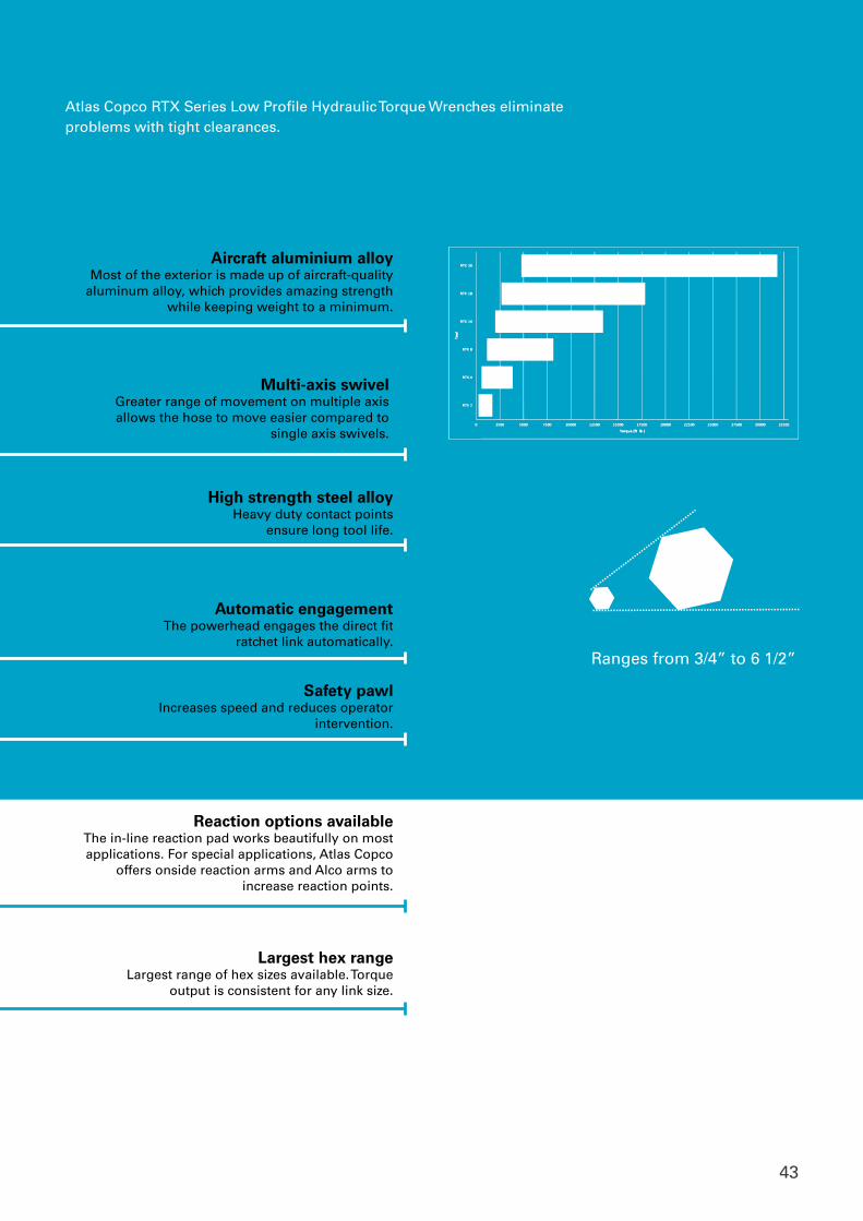
Ranges from 3/4” to 6 1/2”
Atlas Copco RTX Series Low Profile Hydraulic Torque Wrenches eliminate problems with tight clearances.
Largest hex rangeLargest range of hex sizes available. Torque
output is consistent for any link size.
High strength steel alloyHeavy duty contact points
ensure long tool life.
Aircraft aluminium alloyMost of the exterior is made up of aircraft-quality
aluminum alloy, which provides amazing strength while keeping weight to a minimum.
Automatic engagementThe powerhead engages the direct fit
ratchet link automatically.
Multi-axis swivel Greater range of movement on multiple axis allows the hose to move easier compared to
single axis swivels.
Reaction options available The in-line reaction pad works beautifully on most applications. For special applications, Atlas Copco
offers onside reaction arms and Alco arms to increase reaction points.
Safety pawl Increases speed and reduces operator
intervention.

44
RTX Series technical information
Model
Dimensions
L NS (based on ratchet link size) R W1 W2
in mm in mm in mm in mm in mm
RTX-02 7.2 183 3/4 – 2-9/16 19-65 0.35 9 1.26 32 1.92 49
RTX-04 9.7 248 1-5/16 - 3-1/8 32-80 0.47 12 1.65 42 2.56 65
RTX-08 12.1 308 1-13/16 - 3-7/8 46-100 0.59 15 2.08 53 3.22 82
RTX-14 14.6 372 2 – 4-5/8 50-120 0.72 18.5 2.48 63 3.89 99
RTX-18 15.5 393 3 - 5-1/2 75-140 0.87 22.2 2.75 70 4.37 111
RTX-30 18 457 3-9/16- 6-1/8 90-155 1 25.4 3.26 83 5.28 132
Model
Ratchet Link Hex Size* Torque Range Weight
Ordering No.in mm ft.lb. Nm lb kg
RTX-02 3/4 – 2-3/4 19-65 257-1710 348-2318 4.5 2 8434 2021 90
RTX-04 1 - 3-1/8 25-85 578-3855 784-5227 9.7 4.4 8434 2021 95
RTX-08 1-5/8 - 4-1/8 46-105 1223-8151 1658-11051 19.5 9 8434 2022 00
RTX-14 2-1/2 – 5-3/8 60-135 2010-13400 2725-18168 33 15 8434 2116 58
RTX-18 3-1/2 -5-1/2 75-140 2861-19074 3879-25861 51 23 8434 2022 05
RTX-30 3-1/2 -6-1/2 90-165 4770-31800 6467-43114 78 35.5 8434 2022 10
Designs and specifications are subject to change without notice or obligation.
45
1 2
1
2
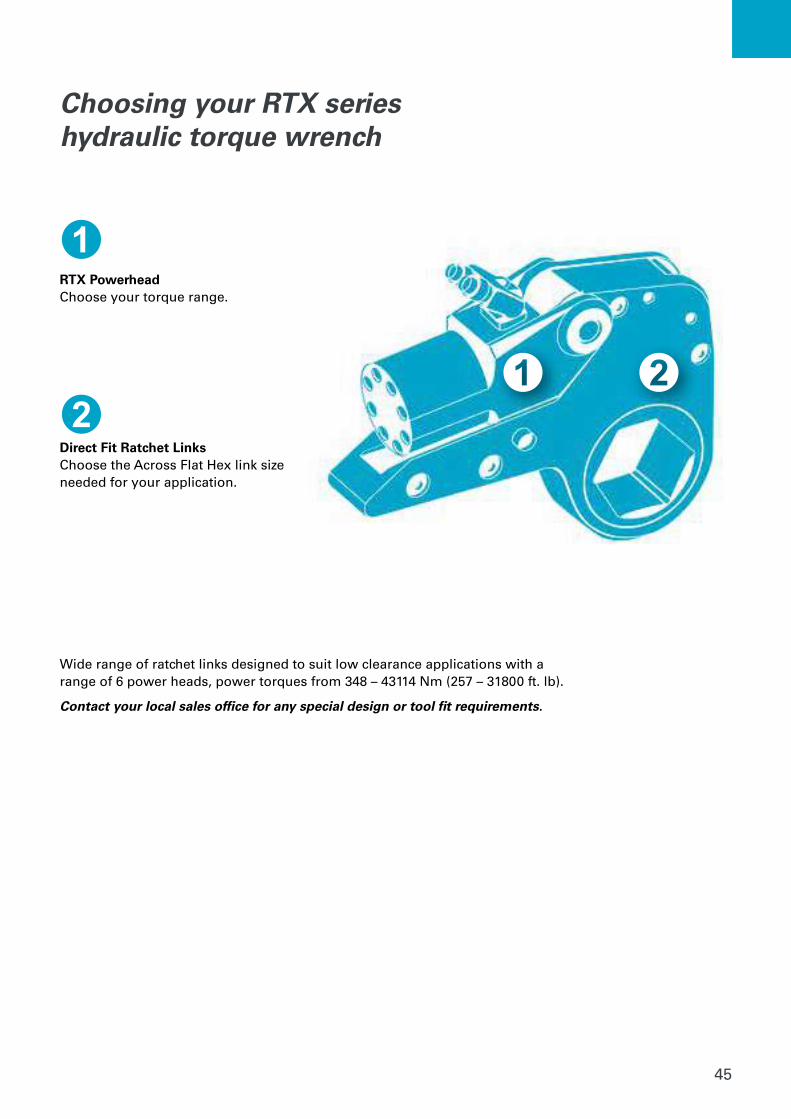
Choosing your RTX series hydraulic torque wrench
RTX PowerheadChoose your torque range.
Direct Fit Ratchet LinksChoose the Across Flat Hex link size needed for your application.
Wide range of ratchet links designed to suit low clearance applications with a range of 6 power heads, power torques from 348 – 43114 Nm (257 – 31800 ft. lb).
Contact your local sales office for any special design or tool fit requirements.
46
Nominal Hexagon A/F Inch Metric
Link Ref.
ModelPTD Ordering
No.
17 #1 RL02-17MM 8434 2132 41
3/4" 19 #1 RL02-012/19MM 8434 2131 84
13/16" #1 RL02-013 8434 2131 87
7/8" 22 #1 RL02-014/22MM 8434 2020 00
15/16" 24 #1 RL02-24MM 8434 2020 54
1" #1 RL02-100 8434 2020 03
1-1/16" 27 #1 RL02-101/27MM 8434 2131 96
1-1/8" #1 RL02-102 8434 2131 99
1-3/16" 30 #2 RL02-103/30MM 8434 2132 05
1-1/4" 32 #2 RL02-104/32MM 8434 2132 08
1-5/16" #3 RL02-105 8434 2132 14
34 #3 RL02-34MM 8434 2132 81
1-7/16" 36 #3 RL02-107/36MM 8434 2021 68
1-1/2" #4 RL02-108 8434 2132 30
1-9/16" #4 RL02-109 8434 2132 23
1-5/8" 41 #4 RL02-110/41MM 8434 2021 07
1-11/16" #5 RL02-111 8434 2132 26
1-3/4” #5 RL02-112 8434 2132 29
1-13/16” 46 #5 RL02-113/46MM 8434 2132 32
1-7/8" #6 RL02-114 8434 2020 06
1-15/16" #6 RL02-115 8434 2132 38
50 #6 RL02-50MM 8434 2021 86
2" #6 RL02-200 8434 2132 50
2-1/16" #7 RL02-201 8434 2132 53
2-1/8" #7 RL02-202 8434 2132 56
2-3/16" 55 #7 RL02-203/55MM 8434 2132 59
2-1/4" #8 RL02-204 8434 2132 62
58 #8 RL02-58MM 8434 2132 89
2-5/16" #8 RL02-205 8434 2132 65
2-3/8" 60 #8 RL02-206/60MM 8434 2021 47
2-7/16" #9 RL02-207 8434 2132 68
2-1/2" #9 RL02-208 8434 2132 71
2-9/16" 65 #9 RL02-209/65MM 8434 2021 50
2-5/8" #10 RL02-210 8434 2021 51
2-3/4" 70 #10 RL02-212/70MM 8434 2059 29
2-13/16" #11 RL02-213 13/16 8434 2021 60
2-15/16" 75 #11 RL02-215/75MM 8434 2132 92
Nominal Hexagon A/F Inch Metric
Link Ref.
ModelPTD Ordering
No.
15 #1 RL04-15MM 8434 2133 47
17 #1 RL04-17MM 8434 2133 48
7/8" 22 #1 RL04-014/24MM 8434 2133 19
15/16" 24 #1 RL04-24MM 8434 2133 93
1" #1 RL04-100 8434 2133 22
1-1/16" 27 #1 RL04-101/27MM 8434 2020 63
1-1/8" #1 RL02-102 8434 2133 23
1-3/16" 30 #1 RL04-103/30MM 8434 2133 25
1-1/4" 32 #1 RL04-104/32MM 8434 2020 15
1-5/16" #1 RL04-105 8434 2133 32
1-7/16" 36 #1 RL04-107/36MM 8434 2020 09
1-1/2" #2 RL04-108 8434 2133 40
1-9/16" #2 RL04-109 8434 2133 41
1-5/8" 41 #2 RL04-110/41MM 8434 2021 35
1-11/16" #3 RL04-111 8434 2020 12
1-3/4” #3 RL04-112 8434 2020 60
1-13/16” 46 #3 RL04-113/46MM 8434 2021 53
1-7/8" #4 RL04-114 8434 2133 43
1-15/16" #4 RL04-115 8434 2133 46
50 #4 RL04-50MM 8434 2134 30
2" #4 RL04-200 8434 2133 49
2-1/16" #5 RL04-201 8434 2133 52
2-1/8" #5 RL04-202 8434 2133 55
2-3/16" 55 #5 RL04-203/55MM 8434 2021 71
2-1/4" #6 RL04-204 8434 2133 58
58 #6 RL04-58MM 8434 2134 42
2-5/16" #6 RL04-205 8434 2133 61
2-3/8" 60 #6 RL04-206/60MM 8434 2133 64
2-7/16" #7 RL04-207 8434 2133 65
2-1/2" #7 RL04-208 8434 2133 67
2-9/16" 65 #7 RL04-209/65MM 8434 2133 70
2-5/8" #8 RL04-210 8434 2133 73
2-3/4" 70 #8 RL04-212/70MM 8434 2021 62
2-13/16" #9 RL04-213 8434 2133 85
2-15/16" 75 #9 RL04-215/75MM 8434 2020 21
3" #10 RL04-300 8434 2134 00
77 #10 RL04-77MM 8434 2020 22
3-1/16" #10 RL04-301 8434 2134 03
3-1/8" #10 RL04-302 8434 2134 06
80 #10 RL04-80MM 8434 2134 51
3-3/16" #10 RL04-303 8434 2134 07
85 #11 RL04-85MM 8434 2134 54
3-3/8" #11 RL04-306 8434 2134 08
3-1/2" #12 RL04-308 8434 2134 09
90 #12 RL04-90MM 8434 2059 30
3-3/4" 95 #13 RL04-312/95MM 8434 2059 31
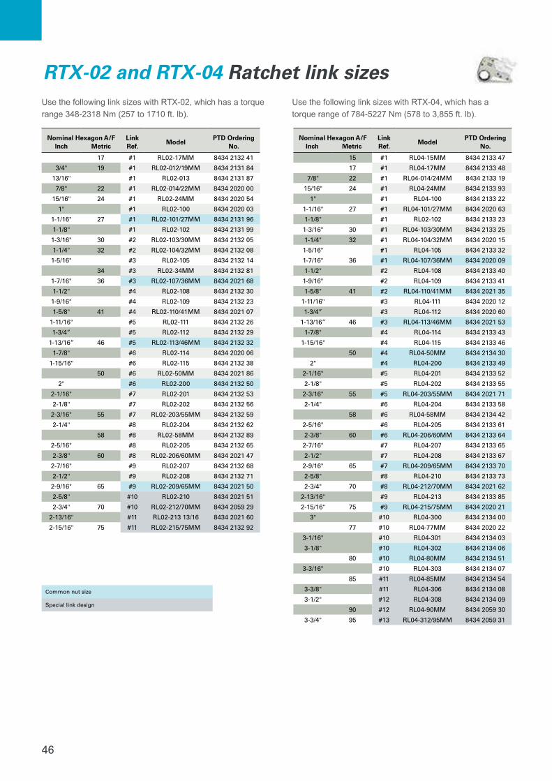
RTX-02 and RTX-04 Ratchet link sizesUse the following link sizes with RTX-02, which has a torque range 348-2318 Nm (257 to 1710 ft. lb).
Use the following link sizes with RTX-04, which has a torque range of 784-5227 Nm (578 to 3,855 ft. lb).
Common nut size
Special link design
47
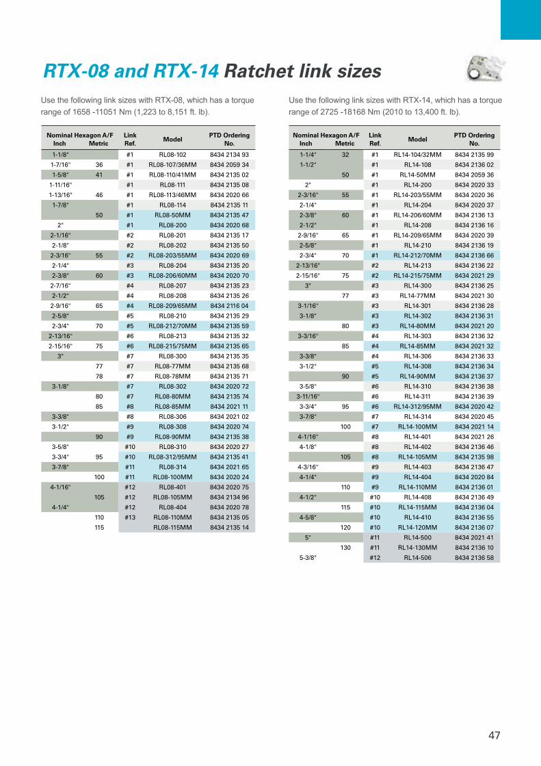
RTX-08 and RTX-14 Ratchet link sizes
Nominal Hexagon A/F Inch Metric
Link Ref.
ModelPTD Ordering
No.
1-1/8" #1 RL08-102 8434 2134 93
1-7/16" 36 #1 RL08-107/36MM 8434 2059 34
1-5/8" 41 #1 RL08-110/41MM 8434 2135 02
1-11/16" #1 RL08-111 8434 2135 08
1-13/16" 46 #1 RL08-113/46MM 8434 2020 66
1-7/8" #1 RL08-114 8434 2135 11
50 #1 RL08-50MM 8434 2135 47
2" #1 RL08-200 8434 2020 68
2-1/16" #2 RL08-201 8434 2135 17
2-1/8" #2 RL08-202 8434 2135 50
2-3/16" 55 #2 RL08-203/55MM 8434 2020 69
2-1/4" #3 RL08-204 8434 2135 20
2-3/8" 60 #3 RL08-206/60MM 8434 2020 70
2-7/16" #4 RL08-207 8434 2135 23
2-1/2" #4 RL08-208 8434 2135 26
2-9/16" 65 #4 RL08-209/65MM 8434 2116 04
2-5/8" #5 RL08-210 8434 2135 29
2-3/4" 70 #5 RL08-212/70MM 8434 2135 59
2-13/16" #6 RL08-213 8434 2135 32
2-15/16" 75 #6 RL08-215/75MM 8434 2135 65
3" #7 RL08-300 8434 2135 35
77 #7 RL08-77MM 8434 2135 68
78 #7 RL08-78MM 8434 2135 71
3-1/8" #7 RL08-302 8434 2020 72
80 #7 RL08-80MM 8434 2135 74
85 #8 RL08-85MM 8434 2021 11
3-3/8" #8 RL08-306 8434 2021 02
3-1/2" #9 RL08-308 8434 2020 74
90 #9 RL08-90MM 8434 2135 38
3-5/8" #10 RL08-310 8434 2020 27
3-3/4" 95 #10 RL08-312/95MM 8434 2135 41
3-7/8" #11 RL08-314 8434 2021 65
100 #11 RL08-100MM 8434 2020 24
4-1/16" #12 RL08-401 8434 2020 75
105 #12 RL08-105MM 8434 2134 96
4-1/4" #12 RL08-404 8434 2020 78
110 #13 RL08-110MM 8434 2135 05
115 RL08-115MM 8434 2135 14
Nominal Hexagon A/F Inch Metric
Link Ref.
ModelPTD Ordering
No.
1-1/4" 32 #1 RL14-104/32MM 8434 2135 99
1-1/2" #1 RL14-108 8434 2136 02
50 #1 RL14-50MM 8434 2059 36
2" #1 RL14-200 8434 2020 33
2-3/16" 55 #1 RL14-203/55MM 8434 2020 36
2-1/4" #1 RL14-204 8434 2020 37
2-3/8" 60 #1 RL14-206/60MM 8434 2136 13
2-1/2" #1 RL14-208 8434 2136 16
2-9/16" 65 #1 RL14-209/65MM 8434 2020 39
2-5/8" #1 RL14-210 8434 2136 19
2-3/4" 70 #1 RL14-212/70MM 8434 2136 66
2-13/16" #2 RL14-213 8434 2136 22
2-15/16" 75 #2 RL14-215/75MM 8434 2021 29
3" #3 RL14-300 8434 2136 25
77 #3 RL14-77MM 8434 2021 30
3-1/16" #3 RL14-301 8434 2136 28
3-1/8" #3 RL14-302 8434 2136 31
80 #3 RL14-80MM 8434 2021 20
3-3/16" #4 RL14-303 8434 2136 32
85 #4 RL14-85MM 8434 2021 32
3-3/8" #4 RL14-306 8434 2136 33
3-1/2" #5 RL14-308 8434 2136 34
90 #5 RL14-90MM 8434 2136 37
3-5/8" #6 RL14-310 8434 2136 38
3-11/16" #6 RL14-311 8434 2136 39
3-3/4" 95 #6 RL14-312/95MM 8434 2020 42
3-7/8" #7 RL14-314 8434 2020 45
100 #7 RL14-100MM 8434 2021 14
4-1/16" #8 RL14-401 8434 2021 26
4-1/8" #8 RL14-402 8434 2136 46
105 #8 RL14-105MM 8434 2135 98
4-3/16" #9 RL14-403 8434 2136 47
4-1/4" #9 RL14-404 8434 2020 84
110 #9 RL14-110MM 8434 2136 01
4-1/2" #10 RL14-408 8434 2136 49
115 #10 RL14-115MM 8434 2136 04
4-5/8" #10 RL14-410 8434 2136 55
120 #10 RL14-120MM 8434 2136 07
5" #11 RL14-500 8434 2021 41
130 #11 RL14-130MM 8434 2136 10
5-3/8" #12 RL14-506 8434 2136 58
Use the following link sizes with RTX-08, which has a torque range of 1658 -11051 Nm (1,223 to 8,151 ft. lb).
Use the following link sizes with RTX-14, which has a torque range of 2725 -18168 Nm (2010 to 13,400 ft. lb).
48
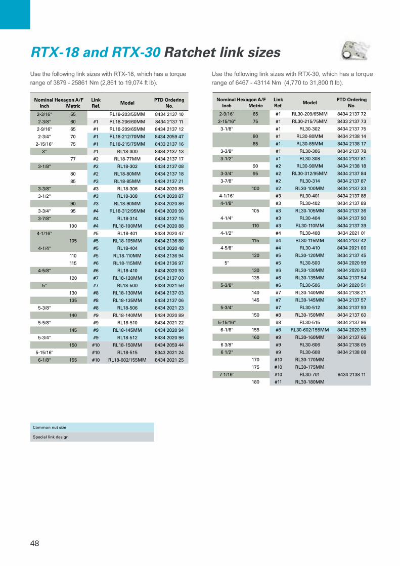
RTX-18 and RTX-30 Ratchet link sizes
Nominal Hexagon A/F Inch Metric
Link Ref.
ModelPTD Ordering
No.
2-3/16" 55 RL18-203/55MM 8434 2137 10
2-3/8" 60 #1 RL18-206/60MM 8434 2137 11
2-9/16" 65 #1 RL18-209/65MM 8434 2137 12
2-3/4" 70 #1 RL18-212/70MM 8434 2059 47
2-15/16" 75 #1 RL18-215/75MM 8433 2137 16
3" #1 RL18-300 8434 2137 13
77 #2 RL18-77MM 8434 2137 17
3-1/8" #2 RL18-302 8434 2137 08
80 #2 RL18-80MM 8434 2137 18
85 #3 RL18-85MM 8434 2137 21
3-3/8" #3 RL18-306 8434 2020 85
3-1/2" #3 RL18-308 8434 2020 87
90 #3 RL18-90MM 8434 2020 86
3-3/4" 95 #4 RL18-312/95MM 8434 2020 90
3-7/8" #4 RL18-314 8434 2137 15
100 #4 RL18-100MM 8434 2020 88
4-1/16" #5 RL18-401 8434 2020 47
105 #5 RL18-105MM 8434 2136 88
4-1/4" #5 RL18-404 8434 2020 48
110 #5 RL18-110MM 8434 2136 94
115 #6 RL18-115MM 8434 2136 97
4-5/8" #6 RL18-410 8434 2020 93
120 #7 RL18-120MM 8434 2137 00
5" #7 RL18-500 8434 2021 56
130 #8 RL18-130MM 8434 2137 03
135 #8 RL18-135MM 8434 2137 06
5-3/8" #8 RL18-506 8434 2021 23
140 #9 RL18-140MM 8434 2020 89
5-5/8" #9 RL18-510 8434 2021 22
145 #9 RL18-145MM 8434 2020 94
5-3/4" #9 RL18-512 8434 2020 96
150 #10 RL18-150MM 8434 2059 44
5-15/16" #10 RL18-515 8343 2021 24
6-1/8" 155 #10 RL18-602/155MM 8434 2021 25
Nominal Hexagon A/F Inch Metric
Link Ref.
ModelPTD Ordering
No.
2-9/16" 65 #1 RL30-209/65MM 8434 2137 72
2-15/16" 75 #1 RL30-215/75MM 8433 2137 73
3-1/8" #1 RL30-302 8434 2137 75
80 #1 RL30-80MM 8434 2138 14
85 #1 RL30-85MM 8434 2138 17
3-3/8" #1 RL30-306 8434 2137 78
3-1/2" #1 RL30-308 8434 2137 81
90 #2 RL30-90MM 8434 2138 18
3-3/4" 95 #2 RL30-312/95MM 8434 2137 84
3-7/8" #2 RL30-314 8434 2137 87
100 #2 RL30-100MM 8434 2137 33
4-1/16" #3 RL30-401 8434 2137 88
4-1/8" #3 RL30-402 8434 2137 89
105 #3 RL30-105MM 8434 2137 36
4-1/4" #3 RL30-404 8434 2137 90
110 #3 RL30-110MM 8434 2137 39
4-1/2" #4 RL30-408 8434 2021 01
115 #4 RL30-115MM 8434 2137 42
4-5/8" #4 RL30-410 8434 2021 00
120 #5 RL30-120MM 8434 2137 45
5" #5 RL30-500 8434 2020 99
130 #6 RL30-130MM 8434 2020 53
135 #6 RL30-135MM 8434 2137 54
5-3/8" #6 RL30-506 8434 2020 51
140 #7 RL30-140MM 8434 2138 21
145 #7 RL30-145MM 8434 2137 57
5-3/4" #7 RL30-512 8434 2137 93
150 #8 RL30-150MM 8434 2137 60
5-15/16" #8 RL30-515 8434 2137 96
6-1/8" 155 #8 RL30-602/155MM 8434 2020 59
160 #9 RL30-160MM 8434 2137 66
6 3/8" #9 RL30-606 8434 2138 05
6 1/2" #9 RL30-608 8434 2138 08
170 #10 RL30-170MM
175 #10 RL30-175MM
7 1/16" #10 RL30-701 8434 2138 11
180 #11 RL30-180MM
Use the following link sizes with RTX-18, which has a torque range of 3879 - 25861 Nm (2,861 to 19,074 ft lb).
Use the following link sizes with RTX-30, which has a torque range of 6467 - 43114 Nm (4,770 to 31,800 ft lb).
Common nut size
Special link design

49
Choose your power headThe RTX powers the EA Spanner assembly. Choose your powerhead based on the torque values you will need.
Set up your linkOur link has been designed from the ground up to provide the strength needed while being extremely easy to set up.
Choose your spannerExtreme Access spanners provide the durability and strength of our traditional ratchet links but can fit where traditional links won’t.
EA ToolExtreme access spanner
Minimal spanner width.
Integrated roller feature.
Minimal spanner nose radius.
Secured with a link pin.
The EA Tool is perfect for ultra-tight clearances where our reduced-radius ratchet links for RTX series won’t fit. To choose the best one for your application, follow these steps:
Connects to Atlas Copco RTX powerhead.
50
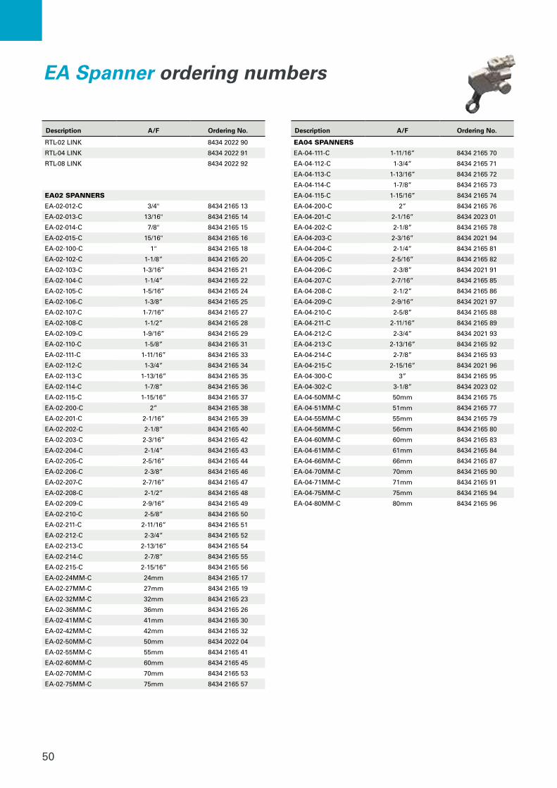
EA Spanner ordering numbers
Description A/F Ordering No.
RTL-02 LINK 8434 2022 90
RTL-04 LINK 8434 2022 91
RTL-08 LINK 8434 2022 92
EA02 SPANNERS
EA-02-012-C 3/4" 8434 2165 13
EA-02-013-C 13/16" 8434 2165 14
EA-02-014-C 7/8" 8434 2165 15
EA-02-015-C 15/16" 8434 2165 16
EA-02-100-C 1" 8434 2165 18
EA-02-102-C 1-1/8” 8434 2165 20
EA-02-103-C 1-3/16” 8434 2165 21
EA-02-104-C 1-1/4” 8434 2165 22
EA-02-105-C 1-5/16” 8434 2165 24
EA-02-106-C 1-3/8” 8434 2165 25
EA-02-107-C 1-7/16” 8434 2165 27
EA-02-108-C 1-1/2” 8434 2165 28
EA-02-109-C 1-9/16” 8434 2165 29
EA-02-110-C 1-5/8” 8434 2165 31
EA-02-111-C 1-11/16” 8434 2165 33
EA-02-112-C 1-3/4” 8434 2165 34
EA-02-113-C 1-13/16” 8434 2165 35
EA-02-114-C 1-7/8” 8434 2165 36
EA-02-115-C 1-15/16” 8434 2165 37
EA-02-200-C 2” 8434 2165 38
EA-02-201-C 2-1/16” 8434 2165 39
EA-02-202-C 2-1/8” 8434 2165 40
EA-02-203-C 2-3/16” 8434 2165 42
EA-02-204-C 2-1/4” 8434 2165 43
EA-02-205-C 2-5/16” 8434 2165 44
EA-02-206-C 2-3/8” 8434 2165 46
EA-02-207-C 2-7/16” 8434 2165 47
EA-02-208-C 2-1/2” 8434 2165 48
EA-02-209-C 2-9/16” 8434 2165 49
EA-02-210-C 2-5/8” 8434 2165 50
EA-02-211-C 2-11/16” 8434 2165 51
EA-02-212-C 2-3/4” 8434 2165 52
EA-02-213-C 2-13/16” 8434 2165 54
EA-02-214-C 2-7/8” 8434 2165 55
EA-02-215-C 2-15/16” 8434 2165 56
EA-02-24MM-C 24mm 8434 2165 17
EA-02-27MM-C 27mm 8434 2165 19
EA-02-32MM-C 32mm 8434 2165 23
EA-02-36MM-C 36mm 8434 2165 26
EA-02-41MM-C 41mm 8434 2165 30
EA-02-42MM-C 42mm 8434 2165 32
EA-02-50MM-C 50mm 8434 2022 04
EA-02-55MM-C 55mm 8434 2165 41
EA-02-60MM-C 60mm 8434 2165 45
EA-02-70MM-C 70mm 8434 2165 53
EA-02-75MM-C 75mm 8434 2165 57
Description A/F Ordering No.
EA04 SPANNERS
EA-04-111-C 1-11/16” 8434 2165 70
EA-04-112-C 1-3/4” 8434 2165 71
EA-04-113-C 1-13/16” 8434 2165 72
EA-04-114-C 1-7/8” 8434 2165 73
EA-04-115-C 1-15/16” 8434 2165 74
EA-04-200-C 2” 8434 2165 76
EA-04-201-C 2-1/16” 8434 2023 01
EA-04-202-C 2-1/8” 8434 2165 78
EA-04-203-C 2-3/16” 8434 2021 94
EA-04-204-C 2-1/4” 8434 2165 81
EA-04-205-C 2-5/16” 8434 2165 82
EA-04-206-C 2-3/8” 8434 2021 91
EA-04-207-C 2-7/16” 8434 2165 85
EA-04-208-C 2-1/2” 8434 2165 86
EA-04-209-C 2-9/16” 8434 2021 97
EA-04-210-C 2-5/8” 8434 2165 88
EA-04-211-C 2-11/16” 8434 2165 89
EA-04-212-C 2-3/4” 8434 2021 93
EA-04-213-C 2-13/16” 8434 2165 92
EA-04-214-C 2-7/8” 8434 2165 93
EA-04-215-C 2-15/16” 8434 2021 96
EA-04-300-C 3” 8434 2165 95
EA-04-302-C 3-1/8” 8434 2023 02
EA-04-50MM-C 50mm 8434 2165 75
EA-04-51MM-C 51mm 8434 2165 77
EA-04-55MM-C 55mm 8434 2165 79
EA-04-56MM-C 56mm 8434 2165 80
EA-04-60MM-C 60mm 8434 2165 83
EA-04-61MM-C 61mm 8434 2165 84
EA-04-66MM-C 66mm 8434 2165 87
EA-04-70MM-C 70mm 8434 2165 90
EA-04-71MM-C 71mm 8434 2165 91
EA-04-75MM-C 75mm 8434 2165 94
EA-04-80MM-C 80mm 8434 2165 96
51
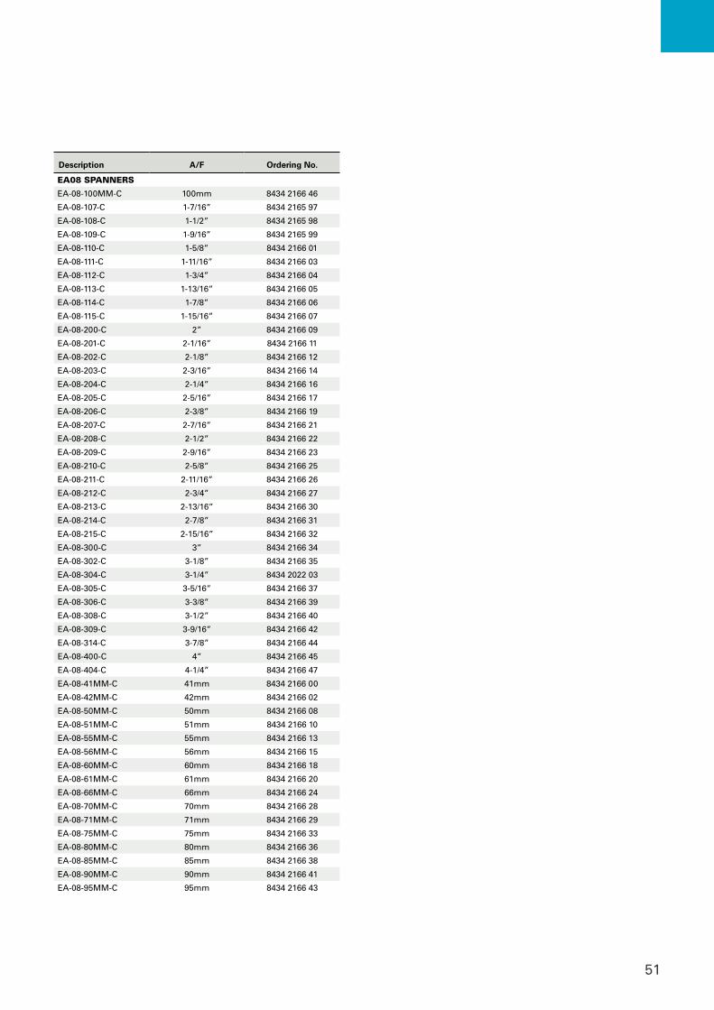
Description A/F Ordering No.
EA08 SPANNERS
EA-08-100MM-C 100mm 8434 2166 46
EA-08-107-C 1-7/16” 8434 2165 97
EA-08-108-C 1-1/2” 8434 2165 98
EA-08-109-C 1-9/16” 8434 2165 99
EA-08-110-C 1-5/8” 8434 2166 01
EA-08-111-C 1-11/16” 8434 2166 03
EA-08-112-C 1-3/4” 8434 2166 04
EA-08-113-C 1-13/16” 8434 2166 05
EA-08-114-C 1-7/8” 8434 2166 06
EA-08-115-C 1-15/16” 8434 2166 07
EA-08-200-C 2” 8434 2166 09
EA-08-201-C 2-1/16” 8434 2166 11
EA-08-202-C 2-1/8” 8434 2166 12
EA-08-203-C 2-3/16” 8434 2166 14
EA-08-204-C 2-1/4” 8434 2166 16
EA-08-205-C 2-5/16” 8434 2166 17
EA-08-206-C 2-3/8” 8434 2166 19
EA-08-207-C 2-7/16” 8434 2166 21
EA-08-208-C 2-1/2” 8434 2166 22
EA-08-209-C 2-9/16” 8434 2166 23
EA-08-210-C 2-5/8” 8434 2166 25
EA-08-211-C 2-11/16” 8434 2166 26
EA-08-212-C 2-3/4” 8434 2166 27
EA-08-213-C 2-13/16” 8434 2166 30
EA-08-214-C 2-7/8” 8434 2166 31
EA-08-215-C 2-15/16” 8434 2166 32
EA-08-300-C 3” 8434 2166 34
EA-08-302-C 3-1/8” 8434 2166 35
EA-08-304-C 3-1/4” 8434 2022 03
EA-08-305-C 3-5/16” 8434 2166 37
EA-08-306-C 3-3/8” 8434 2166 39
EA-08-308-C 3-1/2” 8434 2166 40
EA-08-309-C 3-9/16” 8434 2166 42
EA-08-314-C 3-7/8” 8434 2166 44
EA-08-400-C 4” 8434 2166 45
EA-08-404-C 4-1/4” 8434 2166 47
EA-08-41MM-C 41mm 8434 2166 00
EA-08-42MM-C 42mm 8434 2166 02
EA-08-50MM-C 50mm 8434 2166 08
EA-08-51MM-C 51mm 8434 2166 10
EA-08-55MM-C 55mm 8434 2166 13
EA-08-56MM-C 56mm 8434 2166 15
EA-08-60MM-C 60mm 8434 2166 18
EA-08-61MM-C 61mm 8434 2166 20
EA-08-66MM-C 66mm 8434 2166 24
EA-08-70MM-C 70mm 8434 2166 28
EA-08-71MM-C 71mm 8434 2166 29
EA-08-75MM-C 75mm 8434 2166 33
EA-08-80MM-C 80mm 8434 2166 36
EA-08-85MM-C 85mm 8434 2166 38
EA-08-90MM-C 90mm 8434 2166 41
EA-08-95MM-C 95mm 8434 2166 43
52
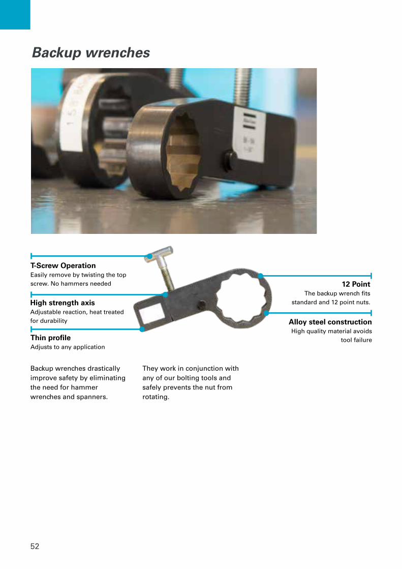
Backup wrenches drastically improve safety by eliminating the need for hammer wrenches and spanners.
They work in conjunction with any of our bolting tools and safely prevents the nut from rotating.
Backup wrenches
High strength axisAdjustable reaction, heat treated for durability
Thin profileAdjusts to any application
12 PointThe backup wrench fits
standard and 12 point nuts.
Alloy steel constructionHigh quality material avoids
tool failure
T-Screw OperationEasily remove by twisting the top screw. No hammers needed
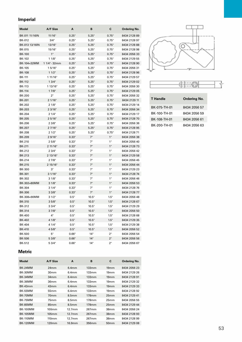
53
T Handle Ordering No.
BK-075-TH-01 8434 2056 57
BK-100-TH-01 8434 2056 59
BK-108-TH-01 8434 2056 61
BK-200-TH-01 8434 2056 63
Imperial
Model A/F Size A B C Ordering No.
BK-011 11/16IN 11/16" 0.25" 5.25" 0.75" 8434 2128 89
BK-012 3/4" 0.25" 5.25" 0.75" 8434 2128 97
BK-013 13/16IN 13/16" 0.25" 5.25" 0.75" 8434 2128 88
BK-015 15/16" 0.25" 5.25" 0.75" 8434 2128 98
BK-100 1" 0.25" 5.25" 0.75" 8434 2056 33
BK-102 1 1/8" 0.25" 5.25" 0.75" 8434 2129 55
BK-104=32MM 1 1/4"- 32mm 0.25" 5.25" 0.75" 8434 2128 90
BK-105 1 5/16" 0.25" 5.25" 0.75" 8434 2056 31
BK-108 1 1/2" 0.25" 5.25" 0.75" 8434 2128 96
BK-111 1 11/16" 0.25" 5.25" 0.75" 8434 2129 57
BK-112 1 3/4" 0.25" 5.25" 0.75" 8434 2129 02
BK-113 1 13/16" 0.25" 5.25" 0.75" 8434 2056 30
BK-114 1 7/8" 0.25" 5.25" 0.75" 8434 2129 05
BK-200 2" 0.25" 5.25" 0.75" 8434 2056 32
BK-201 2 1/16" 0.25" 5.25" 0.75" 8434 2129 11
BK-202 2 1/8" 0.25" 5.25" 0.75" 8434 2129 14
BK-203 2 3/16" 0.25" 5.25" 0.75" 8434 2056 34
BK-204 2 1/4" 0.25" 5.25" 0.75" 8434 2129 17
BK-205 2 5/16" 0.25" 5.25" 0.75" 8434 2128 70
BK-206 2 3/8" 0.25" 5.25" 0.75" 8434 2056 36
BK-207 2 7/16" 0.25" 5.25" 0.75" 8434 2128 95
BK-208 2 1/2" 0.25" 5.25" 0.75" 8434 2128 71
BK-209 2 9/16" 0.33" 7" 1" 8434 2056 38
BK-210 2 5/8" 0.33" 7" 1" 8434 2056 40
BK-211 2 11/16" 0.33" 7" 1" 8434 2128 73
BK-212 2 3/4" 0.33" 7" 1" 8434 2056 42
BK-213 2 13/16" 0.33" 7" 1" 8434 2129 58
BK-214 2 7/8" 0.33" 7" 1" 8434 2056 45
BK-215 2 15/16" 0.33" 7" 1" 8434 2056 44
BK-300 3" 0.33" 7" 1" 8434 2129 23
BK-301 3 1/16" 0.33" 7" 1" 8434 2128 74
BK-302 3 1/8" 0.33" 7" 1" 8434 2056 46
BK-302=80MM 3 1/8" 0.33" 7" 1" 8434 2056 53
BK-304 3 1/4" 0.33" 7" 1" 8434 2128 76
BK-306 3 3/8" 0.33" 7" 1" 8434 2128 77
BK-308=90MM 3 1/2" 0.5" 10.5" 1.5" 8434 2056 48
BK-310 3 5/8" 0.5" 10.5" 1.5" 8434 2128 67
BK-312 3 3/4" 0.5" 10.5" 1.5" 8434 2129 29
BK-314 3 7/8" 0.5" 10.5" 1.5" 8434 2056 50
BK-400 4" 0.5" 10.5" 1.5" 8434 2128 68
BK-402 4 1/8" 0.5" 10.5" 1.5" 8434 2129 35
BK-404 4 1/4" 0.5" 10.5" 1.5" 8434 2129 38
BK-410 4 5/8" 0.5" 10.5" 1.5" 8434 2056 52
BK-500 5" 0.66" 14" 2" 8434 2056 54
BK-506 5 3/8" 0.66" 14" 2" 8434 2056 56
BK-512 5 3/4" 0.66" 14" 2" 8434 2056 67
Metric
Model A/F Size A B C Ordering No.
BK-24MM 24mm 6.4mm 133mm 19mm 8434 2056 23
BK-30MM 30mm 6.4mm 133mm 19mm 8434 2129 26
BK-34MM 34mm 6.4mm 133mm 19mm 8434 2128 91
BK-36MM 36mm 6.4mm 133mm 19mm 8434 2129 32
BK-43mm 43mm 6.4mm 133mm 19mm 8434 2129 33
BK-55MM 55mm 6.4mm 133mm 19mm 8434 2128 92
BK-70MM 70mm 8.5mm 178mm 25mm 8434 2129 41
BK-75MM 75mm 8.5mm 178mm 25mm 8434 2056 55
BK-85MM 85mm 8.5mm 178mm 25mm 8434 2129 44
BK-100MM 100mm 12.7mm 267mm 38mm 8434 2056 24
BK-105MM 105mm 12.7mm 267mm 38mm 8434 2128 93
BK-110MM 110mm 12.7mm 267mm 38mm 8434 2128 99
BK-120MM 120mm 16.9mm 356mm 50mm 8434 2129 08
54
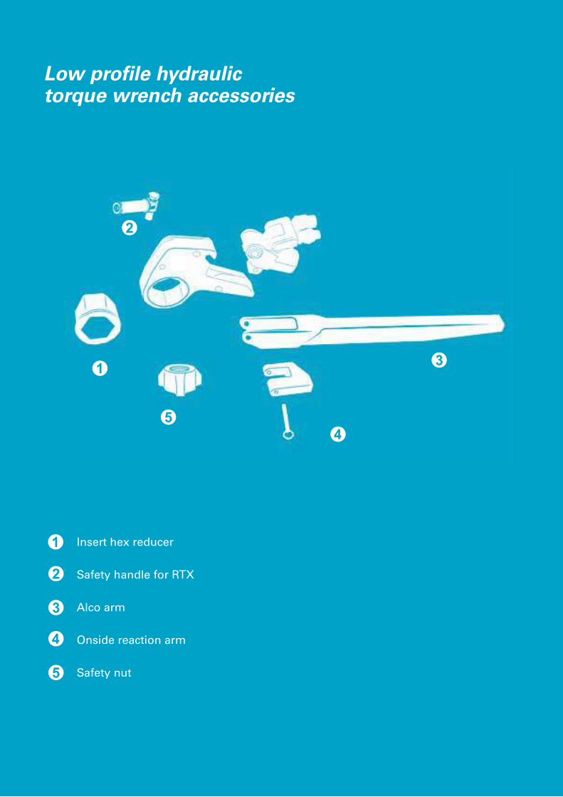
2
3
45
1
Insert hex reducer
Safety handle for RTX
Alco arm
Onside reaction arm
Safety nut
Low profile hydraulic torque wrench accessories

55
RTX Tool accessories
1 2
Model Ordering No.
RTX02-ALC 8434 2057 58
RTX04-ALC 8434 2057 60
RTX08-ALC 8434 2057 62
RTX14-ALC 8434 2057 64
RTX18-ALC 8434 2057 66
RTX30-ALC 8434 2057 67
Model Ordering No.
RTX02-14 4222 2107 14
RTX04-14 4222 2109 27
RTX08-14 4222 2110 44
RTX14-14 4222 2141 22
RTX18-14 4222 2141 23
RTX30-14 4222 2144 43
Stud Size Ordering No.
2" 8434 2129 19
2-1/2" 8434 2129 18
2-1/4" 8434 2129 16
1-7/8" 8434 2129 15
3" 8434 2129 13
2-3/4" 8434 2129 12
1-3/4" 8434 2129 10
1-5/8" 8434 2129 09
1-1/2" 8434 2129 07
1-3/8" 8434 2129 06
1-1/4" 8434 2129 04
1-1/8" 8434 2129 03
1" 8434 2129 01
7/8" 8434 2129 00
3 4 5Alco arm Onside reaction arm
Safety nut
Insert hex reducer
Model Ordering No.
All RTX Tools 8434 2170 31
Support/safety handle
Custom sizes available on request
Starting Size Reduces To Ordering No.
3 1/8 1 5/8 4222 2138 16
3 1/8 1 3/4 4222 2138 19
3 1/8 2 4222 2138 22
3 1/8 2 3/8 4222 2138 25
50mm 19mm 4222 2138 28
50mm 32mm 4222 2138 31
50mm 41mm 4222 2138 34
50mm 42mm 4222 2138 37
50mm 46mm 4222 2138 40
55mm 50mm 4222 2138 43
65mm 55mm 4222 2119 74
70mm 60mm 4222 2119 78
70mm 65mm 4222 2119 82
100mm 80mm 4222 2140 62
2 3/16 2 4222 2140 65
3 1/8 2 15/16 4222 2140 68
3 1/8 50mm 4222 2140 71
3 1/8 55mm 4222 2140 74
3 1/8 60mm 4222 2140 77
3 7/8 3 1/2 4222 2140 80
60mm 50mm 4222 2122 07
60mm 55mm 4222 2122 11
70mm 46mm 4222 2140 83
Starting Size Reduces To Ordering No.
2 3/4 1 5/8 4222 2134 17
2 3/4 1 13/16 4222 2134 20
2 3/4 1 7/8 4222 2134 23
46mm 36mm 4222 2134 26
50mm 41mm 4222 2134 29
50mm 46mm 4222 2134 32
1 13/16 30mm 4222 2119 58
1 13/16 36mm 4222 2119 62
1 13/16 42mm 4222 2119 66
2 1 3/4 4222 2137 74
2 1 13/16 4222 2137 77
2 1/4 1 5/16 4222 2137 80
2 1/4 1 1/2 4222 2137 83
2 1/4 1 7/8 4222 2137 86
2 1/2 1 7/8 4222 2119 70
2 3/4 2 1/2 4222 2137 89
2 3/4 2 1/16 4222 2137 92
2 3/4 2 1/8 4222 2137 95
2 3/4 2 3/16 4222 2137 98
2 3/4 2 1/4 4222 2138 01
2 3/4 2 3/8 4222 2138 04
2 15/16 2 9/16 4222 2138 07
3 1/8 1 4222 2138 10
3 1/8 1 1/2 4222 2138 13

56
Panther 025 Panther 55 Lynx Panther 150
Ordering Numbers
110V w/full frame8434 2040 33
220V w/full frame8434 2059 54
110V8434 2040 35
220V8434 2040 37
110V8434 2059 61
220V8434 2059 59
110V8434 2040 39
220V8434 2040 41
Dimensions (LxWxH)
inches 14.1 x 12.2 x 17.3 17.3 x 12.6 x 16.5 9.5 x 17.14 x 18.12 17.3 x 13 x 17.3 17.3 x 13 x 17.3
mm 360 x 310 x 440 460 x 320 x 420 541.3 x 435.3 x 460.2 440 x 330 x 440 440 x 330 x 440
Weight (w/o / with oil)lb 42.6 / 46.6 61.6 / 70.4 75 64.9 / 73.7 64.9 / 73.7
kg 19.4 / 21.1 28 / 32 34 29.5 / 33.5 29.5 / 33.5
Oil CapacityGallons 0.45 1.05 2.5 1.5 1.5
Liters 1.7 4.0 9.5 4.0 4.0
Intercooler System
No Yes Optional Accessory Yes Yes
Oil Flow@1250psi/86bar
cu.in 195 cu. in/min 391 cu. in/min - 463 cu. in/min 517.6 cu. in/min
l/min 3.2 l/min 6.4 l/min - 7.6 l/min 8.5 l/min
Oil Flow@3600psi/250bar
54 cu. in/min 110 cu. in/min - 183 cu. in/min 207.0 cu. in/min
0.9 l/min 1.8 l/min - 3.0 l/min 4.4 l/min
Oil Flow@10,000psi/700bar
21 cu. in/min 42 cu. in/min 56 cu. in/min 61 cu. in/min 79.1 cu. in/min
0.35 l/min 0.7 l/min 0.9 l/min 1.0 l/min 1.3 l/min
Ports 1 4 1 4
Rec
om
men
ded
Too
ls
RTP5 • • •
RT1 • • •
RT3 • • •
RT5 • •
RT8 • • •
RT10 • • •
RT20 • • •
RT25 • • •
RT50 • • •
RTX2 • • • •
RTX4 • • •
RTX8 • • •
RTX14 • • •
RTX18 • • •
RTX30 • • •
* 4-port manifold is available as an optional accessory. See the pump accessory page for order.
Hoses and oil not included with the pump. Be sure to order corresponding amount of oil for your pump and select hose length for your application.
Electric- Three stage
- Effective oil cooling system- High strength steel frame- Oil filter for enhanced life
- Class 1 gauge (+/- 1% full scale)- Auto shutoff after 1 minute idling
- High temperature protection
Hydraulic torque wrench pumps
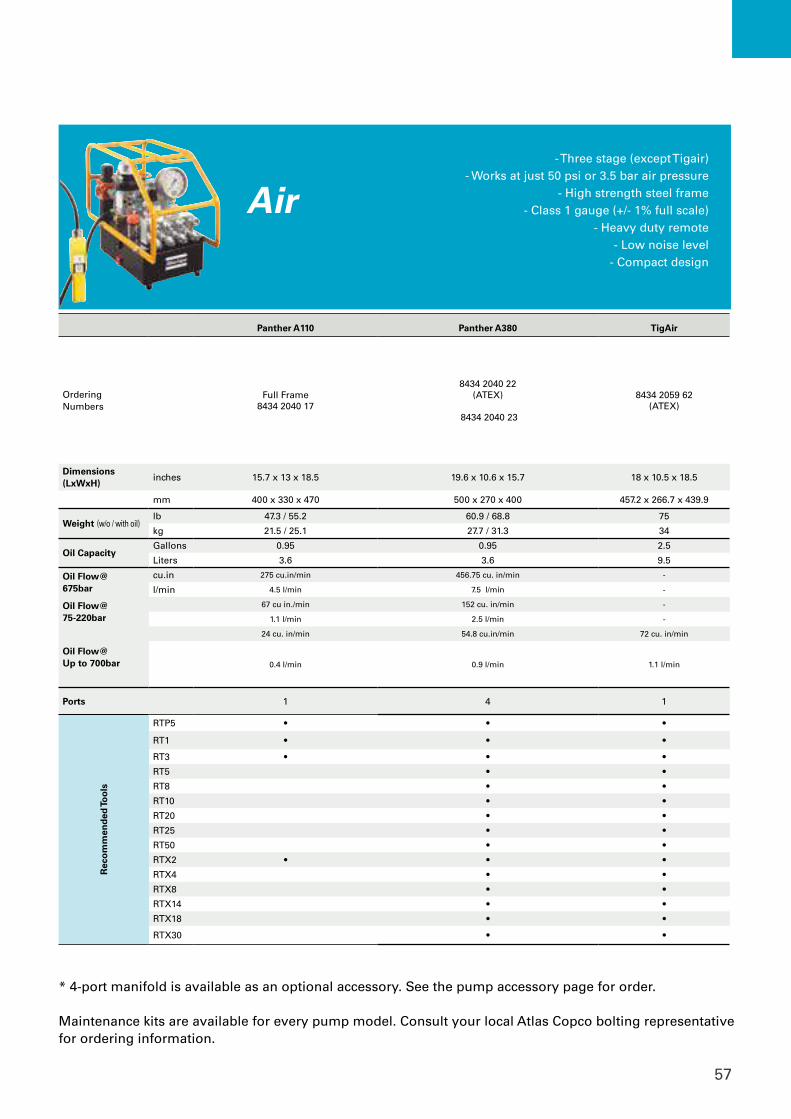
57
Panther A110 Panther A380 TigAir
Ordering Numbers
Full Frame8434 2040 17
8434 2040 22(ATEX)
8434 2040 23
8434 2059 62(ATEX)
Dimensions (LxWxH)
inches 15.7 x 13 x 18.5 19.6 x 10.6 x 15.7 18 x 10.5 x 18.5
mm 400 x 330 x 470 500 x 270 x 400 457.2 x 266.7 x 439.9
Weight (w/o / with oil)lb 47.3 / 55.2 60.9 / 68.8 75
kg 21.5 / 25.1 27.7 / 31.3 34
Oil CapacityGallons 0.95 0.95 2.5
Liters 3.6 3.6 9.5
Oil Flow@675bar
cu.in 275 cu.in/min 456.75 cu. in/min -
l/min 4.5 l/min 7.5 l/min -
Oil Flow@75-220bar
67 cu in./min 152 cu. in/min -
1.1 l/min 2.5 l/min -
Oil Flow@Up to 700bar
24 cu. in/min 54.8 cu.in/min 72 cu. in/min
0.4 l/min 0.9 l/min 1.1 l/min
Ports 1 4 1
Rec
om
men
ded
Too
ls
RTP5 • • •
RT1 • • •
RT3 • • •
RT5 • •
RT8 • •
RT10 • •
RT20 • •
RT25 • •
RT50 • •
RTX2 • • •
RTX4 • •
RTX8 • •
RTX14 • •
RTX18 • •
RTX30 • •
* 4-port manifold is available as an optional accessory. See the pump accessory page for order.
Maintenance kits are available for every pump model. Consult your local Atlas Copco bolting representative for ordering information.
Air- Three stage (except Tigair)
- Works at just 50 psi or 3.5 bar air pressure- High strength steel frame
- Class 1 gauge (+/- 1% full scale)- Heavy duty remote
- Low noise level- Compact design
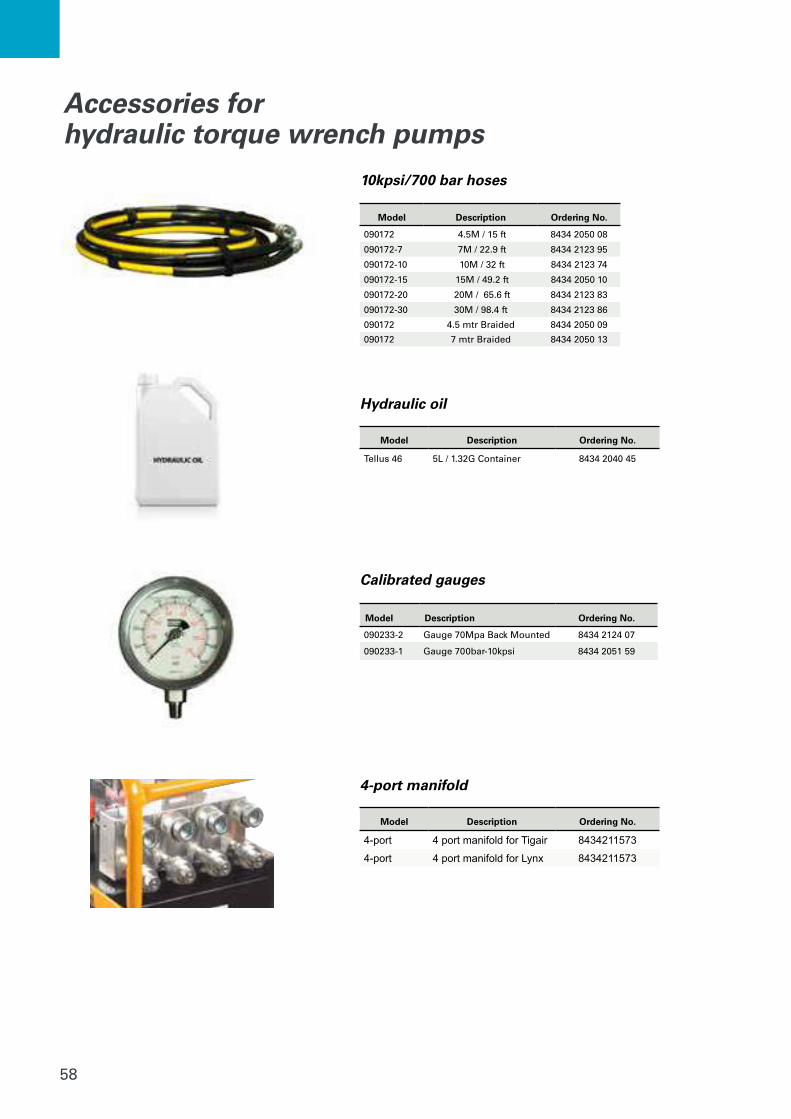
58
Model Description Ordering No.
090172 4.5M / 15 ft 8434 2050 08
090172-7 7M / 22.9 ft 8434 2123 95
090172-10 10M / 32 ft 8434 2123 74
090172-15 15M / 49.2 ft 8434 2050 10
090172-20 20M / 65.6 ft 8434 2123 83
090172-30 30M / 98.4 ft 8434 2123 86
090172 4.5 mtr Braided 8434 2050 09
090172 7 mtr Braided 8434 2050 13
Accessories for hydraulic torque wrench pumps
Model Description Ordering No.
090233-2 Gauge 70Mpa Back Mounted 8434 2124 07
090233-1 Gauge 700bar-10kpsi 8434 2051 59
Calibrated gauges
10kpsi/700 bar hoses
Hydraulic oil
Model Description Ordering No.
Tellus 46 5L / 1.32G Container 8434 2040 45
4-port manifold
Model Description Ordering No.
4-port 4 port manifold for Tigair 8434211573
4-port 4 port manifold for Lynx 8434211573
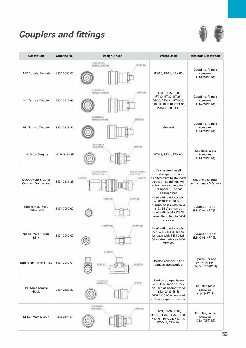
59
Couplers and fittings
Description Ordering No. Design/Shape Where Used Alternate Description
1/8" Coupler Female 8434 2050 06 RT-0.5, RT-01, RTX-02Coupling, female
screw-onX 1/8"NPT (M)
1/4" Female Coupler 8434 2123 41
RT-03, RT-05, RT08,RT-10, RT-20, RT-25,
RT-50, RTX-04, RTX-08, RTX-14, RTX-18, RTX-30,
PUMPS, HOSES.
Coupling, female screw-on
X 1/4"NPT (M)
3/8" Female Coupler 8434 2123 44 GeneralCoupling, female
screw-onX 3/8"NPT (M)
1/8" Male Coupler 8434 2123 65 RT-0.5, RT-01, RTX-02Coupling, male
screw-on X 1/8"NPT (M)
QCCOUPLERS Quick Connect Coupler set
8434 2131 36
Can be used on all wrenches/pumps/hoses
as alternative to standard screw-on couplings. Ad-aptors are also required
(1/4 npt or 1/8 npt as appropriate)
Coupler set, quick connect male & female
Nipple Male-Male 1/4INx1/4IN
8434 2050 00
Used with quick coupler set 8438 2131 36 & on
pumps/ hoses with 8434 2123 38. Also can be
used with 8434 2123 38 as an alternative to 8434
2123 68.
Adaptor, 1/4 npt (M) X 1/4 NPT (M)
Nipple Male 1/4INx-1/8IN
8434 2050 02
Used with quick coupler set 8438 2131 36 & can be used with 8434 2123 38 as alternative to 8434
2123 65
Adaptor, 1/4 npt (M) X 1/8 NPT (M)
Nipple NPT 1/4INx1/4IN 8434 2050 04Used to connect in-line
gauges/ accessories
T-piece, 1/4 npt (M) X 1/4 NPT
(M) X 1/4 NPT (F)
1/4" Male Female Nipple
8434 2123 38
Used on pumps/ hoses with 8434 2050 00. Can
be used as alternative to 8434 2123 68 &
8434 2123 65 when used with appropriate adaptor
Coupler, male screw-on
X 1/4 NPT (F)
M 1/4" Male Nipple 8434 2123 68
RT-03, RT-05, RT08, RT-10, RT-20, RT-25, RT-50, RTX-04, RTX-08, RTX-14,
RTX-18, RTX-30.
Coupling, male screw-on
X 1/4"NPT (M)
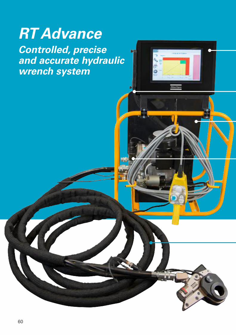
60
RT AdvanceControlled, precise and accurate hydraulic wrench system
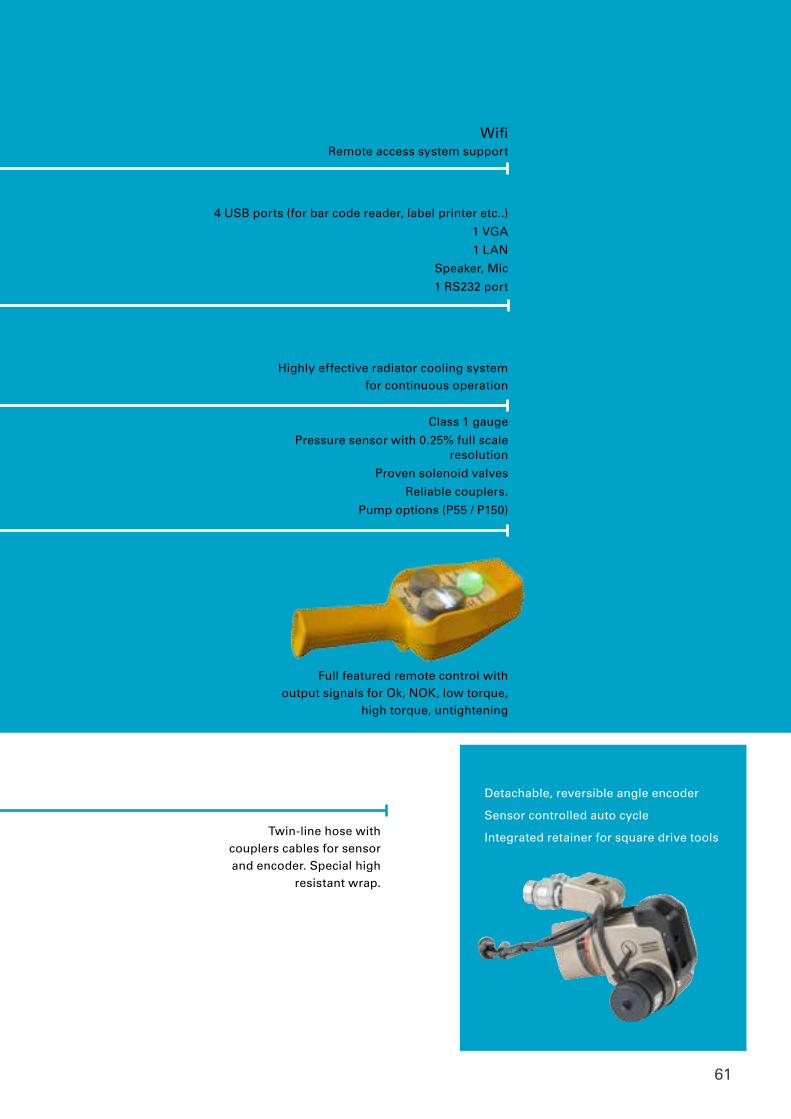
61
Tentec CTSTTensioner Datasheet
Highly effective radiator cooling system for continuous operation
WifiRemote access system support
4 USB ports (for bar code reader, label printer etc..)
1 VGA
1 LAN
Speaker, Mic
1 RS232 port
Class 1 gauge
Pressure sensor with 0.25% full scale resolution
Proven solenoid valves
Reliable couplers.
Pump options (P55 / P150)
Twin-line hose with couplers cables for sensor and encoder. Special high
resistant wrap.
Detachable, reversible angle encoder
Sensor controlled auto cycle
Integrated retainer for square drive tools
Full featured remote control with output signals for Ok, NOK, low torque,
high torque, untightening
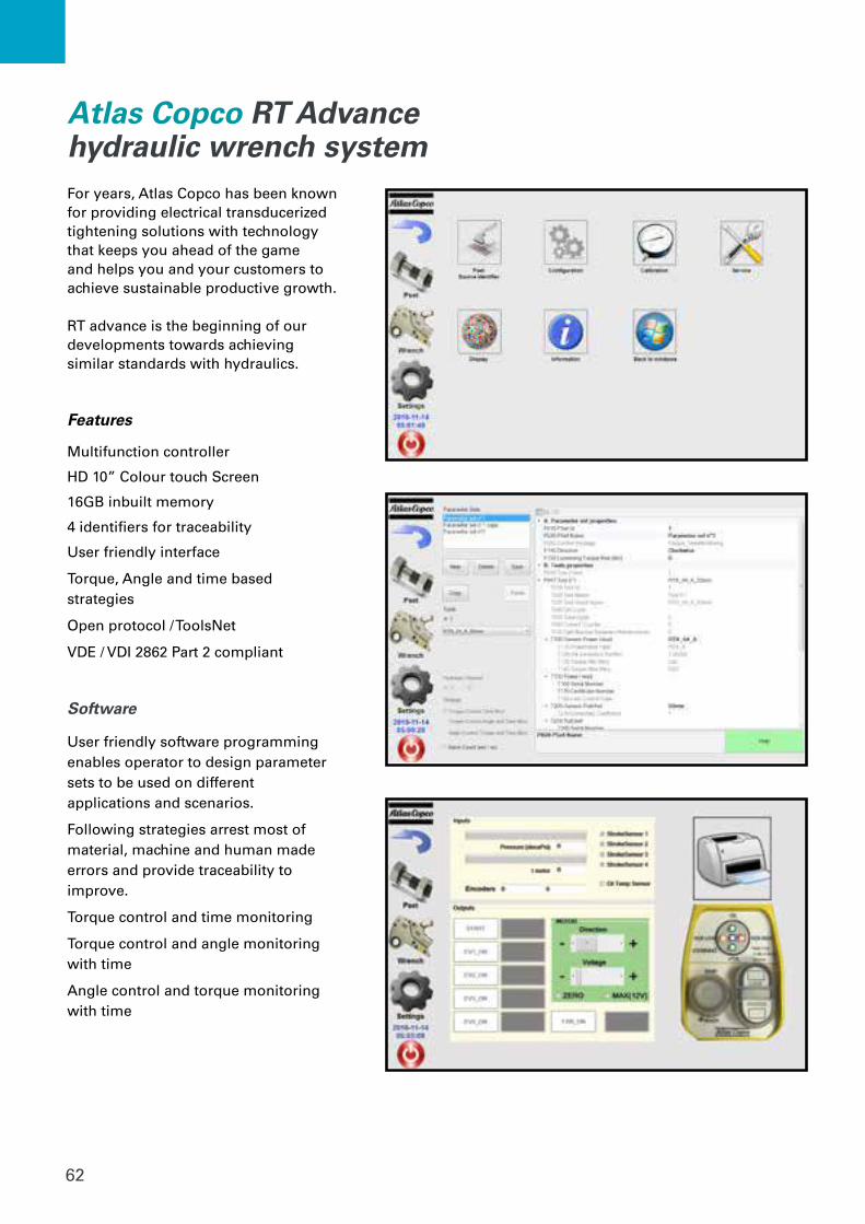
62
Software
User friendly software programming enables operator to design parameter sets to be used on different applications and scenarios.
Following strategies arrest most of material, machine and human made errors and provide traceability to improve.
Torque control and time monitoring
Torque control and angle monitoring with time
Angle control and torque monitoring with time
For years, Atlas Copco has been known for providing electrical transducerized tightening solutions with technology that keeps you ahead of the game and helps you and your customers to achieve sustainable productive growth.
RT advance is the beginning of our developments towards achieving similar standards with hydraulics.
Features
Multifunction controller
HD 10” Colour touch Screen
16GB inbuilt memory
4 identifiers for traceability
User friendly interface
Torque, Angle and time based strategies
Open protocol / ToolsNet
VDE / VDI 2862 Part 2 compliant
Atlas Copco RT Advance hydraulic wrench system
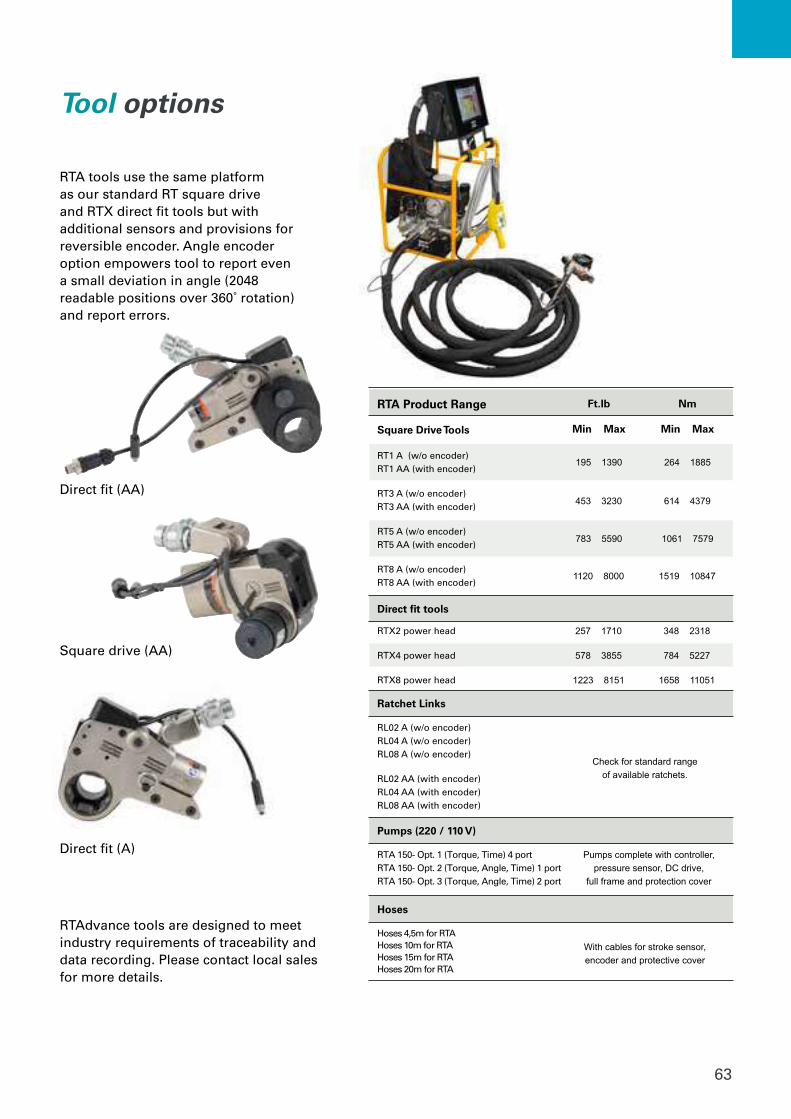
63
RTA tools use the same platform as our standard RT square drive and RTX direct fit tools but with additional sensors and provisions for reversible encoder. Angle encoder option empowers tool to report even a small deviation in angle (2048 readable positions over 360˚ rotation) and report errors.
RTA Product Range
Square Drive Tools
Direct fit tools
Ratchet Links
Pumps (220 / 110 V)
Hoses
RT1 A (w/o encoder) RT1 AA (with encoder)
RT3 A (w/o encoder) RT3 AA (with encoder)
RT5 A (w/o encoder) RT5 AA (with encoder)
RT8 A (w/o encoder) RT8 AA (with encoder)
RTX2 power head
RTX4 power head
RTX8 power head
RL02 A (w/o encoder) RL04 A (w/o encoder) RL08 A (w/o encoder)
RL02 AA (with encoder) RL04 AA (with encoder) RL08 AA (with encoder)
RTA 150- Opt. 1 (Torque, Time) 4 portRTA 150- Opt. 2 (Torque, Angle, Time) 1 portRTA 150- Opt. 3 (Torque, Angle, Time) 2 port
Hoses 4,5m for RTAHoses 10m for RTAHoses 15m for RTAHoses 20m for RTA
Check for standard range of available ratchets.
Pumps complete with controller, pressure sensor, DC drive,
full frame and protection cover
With cables for stroke sensor, encoder and protective cover
195 1390 264 1885
453 3230 614 4379
783 5590 1061 7579
1120 8000 1519 10847
257 1710
578 3855
1223 8151
348 2318
784 5227
1658 11051
Ft.lb
Min Max
Nm
Min Max
Tool options
RTAdvance tools are designed to meet industry requirements of traceability and data recording. Please contact local sales for more details.
Direct fit (AA)
Square drive (AA)
Direct fit (A)

64
Reaction free operation
Custom engineering
Simultaneoustensioning
Hydraulic bolt tensioning systems

65

66
Piston stroke15mm piston/ram stroke capability on models CTST 02 - CTST 06.
VersatileDetachable and Interchangeable bridge component.
Thread insertContains a matching female thread to the bolt being tensioned.
Reliable sealsProven seal technology ensures many 1000’s of tool pressure cycles.
Tentec CTST Topside hydraulic bolt tensioner
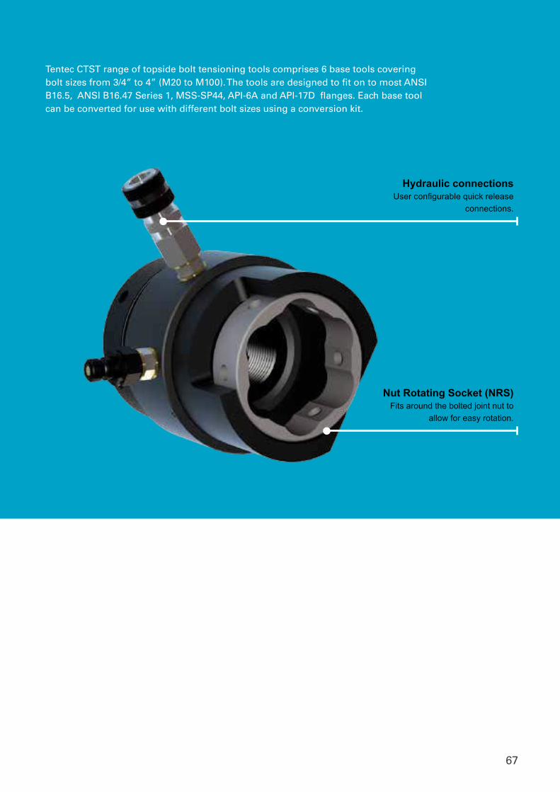
67
Hydraulic connectionsUser configurable quick release
connections.
Nut Rotating Socket (NRS)Fits around the bolted joint nut to
allow for easy rotation.
Tentec CTST range of topside bolt tensioning tools comprises 6 base tools covering bolt sizes from 3/4” to 4” (M20 to M100). The tools are designed to fit on to most ANSI B16.5, ANSI B16.47 Series 1, MSS-SP44, API-6A and API-17D flanges. Each base tool can be converted for use with different bolt sizes using a conversion kit.
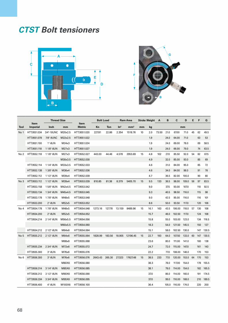
68
F
G
B
A
E
D
C
B
CTST Bolt tensioners
Tool Item
Imperial
Thread SizeItem
Metric
Bolt Load Ram Area Stroke Weight A B C D E F G
Inch mm Kn Ton In² mm² mm kg mm
No 1 HTT.9551.034 3/4"-10UNC M20x2.5 HTT.9551.020 227.81 22.86 2.354 1518.76 10 2.0 73.50 21.0 67.00 71.0 45 62 49.5
HTT.9551.078 7/8"-9UNC M22x2.5 HTT.9551.022 1.9 24.0 64.00 71.0 63 53
HTT.9551.100 1"-8UN M24x3 HTT.9551.024 1.9 24.0 69.00 78.0 69 58.5
HTT.9551.118 1 1/8"-8UN M27x3 HTT.9551.027 1.9 24.0 66.00 79.0 74 63.5
No 2 HTT.9552.118 1 1/8"-8UN M27x3 HTT.9552.027 443.00 44.46 4.578 2953.69 15 4.8 102 27.0 85.50 92.0 54 82 67.5
M30x3.5 HTT.9552.030 4.9 32.0 85.00 93.0 85 69
HTT.9552.114 1 1/4"-8UN M33x3.5 HTT.9552.033 4.6 31.0 84.00 95.0 85 72
HTT.9552.138 1 3/8"-8UN M36x4 HTT.9552.036 4.6 34.0 84.00 98.0 91 78
HTT.9552.112 1 1/2"-8UN M39x4 HTT.9552.039 4.7 36.5 82.00 100.0 90 80
No 3 HTT.9553.112 1 1/2"-8UN M39x4 HTT.9553.039 810.85 81.38 8.379 5405.70 15 9.5 133 36.5 98.00 109.0 56 97 83.5
HTT.9553.158 1 5/8"-8UN M42x4.5 HTT.9553.042 9.0 37.5 93.00 107.0 110 92.5
HTT.9553.134 1 3/4"-8UN M45x4.5 HTT.9553.045 9.3 40.5 98.50 116.0 115 98
HTT.9553.178 1 7/8"-8UN M48x5 HTT.9553.048 9.0 42.5 95.00 116.0 116 101
HTT.9553.200 2"-8UN M52x5 HTT.9553.052 8.6 50.0 93.50 117.0 120 106
No 4 HTT.9554.178 1 7/8"-8UN M48x5 HTT.9554.048 1273.16 127.78 13.159 8489.96 15 16.1 163 43.5 106.00 118.0 57 130 108
HTT.9554.200 2"-8UN M52x5 HTT.9554.052 15.7 46.0 102.50 117.0 124 108
HTT.9554.214 2 1/4"-8UN M56x5.5 HTT.9554.056 15.8 55.0 103.00 123.0 134 118.5
M60x5.5 HTT.9554.060 18.3 54.0 121.50 145.5 150 127
HTT.9554.212 2 1/2"-8UN M64x6 HTT.9554.064 15.1 58.0 102.50 130.0 147 130.5
No 5 HTT.9555.212 2 1/2"-8UN M64x6 HTT.9555.064 1828.99 183.56 18.905 12196.45 15 22.7 193 64.0 107.50 133.0 60 147 130.5
M68x6 HTT.9555.068 23.6 80.0 111.00 141.0 160 138
HTT.9555.234 2 3/4"-8UN M72x6 HTT.9555.072 24.7 72.0 115.00 147.0 161 143
HTT.9555.300 3"-8UN M76x6 HTT.9555.076 22.2 77.0 108.00 146.0 170 153
No 6 HTT.9556.300 3"-8UN M76x6 HTT.9556.076 2643.43 265.30 27.323 17627.48 15 38.5 233 77.0 120.00 153.0 64 170 153
M80X6 HTT.9556.080 38.3 78.0 117.00 154.0 178 155.5
HTT.9556.314 3 1/4"-8UN M85X6 HTT.9556.085 38.1 78.0 114.00 154.0 182 165.5
HTT.9556.312 3 1/2"-8UN M90X6 HTT.9556.090 37.0 86.0 114.00 160.0 191 174.5
HTT.9556.334 3 3/4"-8UN M95X6 HTT.9556.095 37.0 99.0 116.00 168.0 210 189.5
HTT.9556.400 4"-8UN M100X6 HTT.9556.100 36.4 105.0 116.00 174.0 220 200

69
Bolt protrusion
CTST-Series tensioners need a minimum of 1 x bolt diameter protruding above the hexagon or round nut.
Item Description Ordering No.
HTT.9551.020 M20 CTST Tensioner 8434 2200 71
HTT.9551.022 M22 CTST Tensioner 8434 2200 73
HTT.9551.024 M24 CTST Tensioner 8434 2200 75
HTT.9551.027 M27 CTST Tensioner 8434 2200 77
HTT.9552.027 M27 CTST Tensioner 8434 2200 80
HTT.9552.030 M30 CTST Tensioner 8434 2200 82
HTT.9552.033 M33 CTST Tensioner 8434 2200 83
HTT.9552.036 M36 CTST Tensioner 8434 2200 85
HTT.9552.039 M39 CTST Tensioner 8434 2200 87
HTT.9553.039 M39 CTST Tensioner 8434 2200 94
HTT.9553.042 M42 CTST Tensioner 8434 2200 95
HTT.9553.045 M45 CTST Tensioner 8434 2200 96
HTT.9553.048 M48 CTST Tensioner 8434 2200 97
HTT.9553.052 M52 CTST Tensioner 8434 2200 98
HTT.9554.048 M48 CTST Tensioner 8434 2201 03
HTT.9554.052 M52 CTST Tensioner 8434 2201 05
HTT.9554.056 M56 CTST Tensioner 8434 2201 06
HTT.9554.060 M60 CTST Tensioner 8434 2201 07
HTT.9554.064 M64 CTST Tensioner 8434 2201 08
HTT.9555.064 M64 CTST Tensioner 8434 2201 13
HTT.9555.068 M68 CTST Tensioner 8434 2201 14
HTT.9555.072 M72 CTST Tensioner 8434 2201 15
HTT.9555.076 M76 CTST Tensioner 8434 2201 16
HTT.9556.076 M76 CTST Tensioner 8434 2201 30
HTT.9556.080 M80 CTST Tensioner 8434 2201 31
HTT.9556.085 M85 CTST Tensioner 8434 2201 32
HTT.9556.090 M90 CTST Tensioner 8434 2201 33
HTT.9556.095 M95 CTST Tensioner 8434 2201 34
HTT.9556.100 M100 CTST Tensioner 8434 2201 35
CTST Ordering numbers
Item Description Ordering No.
HTT.9551.034 3/4" CTST Tensioner 8434 2200 70
HTT.9551.078 7/8" CTST Tensioner 8434 2200 72
HTT.9551.100 1" CTST Tensioner 8434 2200 74
HTT.9551.118 1 1/8" CTST Tensioner 8434 2200 76
HTT.9552.118 1 1/8" CTST Tensioner 8434 2200 79
HTT.9552.114 1 1/4" CTST Tensioner 8434 2200 81
HTT.9552.138 1 3/8" CTST Tensioner 8434 2200 84
HTT.9552.112 1 1/2" CTST Tensioner 8434 2200 86
HTT.9553.112 1 1/2" CTST Tensioner 8434 2200 89
HTT.9553.158 1 5/8" CTST Tensioner 8434 2200 90
HTT.9553.134 1 3/4" CTST Tensioner 8434 2200 91
HTT.9553.178 1 7/8" CTST Tensioner 8434 2200 92
HTT.9553.200 2" CTST Tensioner 8434 2200 93
HTT.9554.178 1 7/8" CTST Tensioner 8434 2201 00
HTT.9554.200 2" CTST Tensioner 8434 2201 01
HTT.9554.214 2 1/4" CTST Tensioner 8434 2201 04
HTT.9554.212 2 1/2" CTST Tensioner 8434 2201 02
HTT.9555.212 2 1/2" CTST Tensioner 8434 2201 10
HTT.9555.234 2 3/4" CTST Tensioner 8434 2201 11
HTT.9555.300 3" CTST Tensioner 8434 2201 12
HTT.9556.300 3" CTST Tensioner 8434 2201 26
HTT.9556.314 3 1/4" CTST Tensioner 8434 2201 25
HTT.9556.312 3 1/2" CTST Tensioner 8434 2201 27
HTT.9556.334 3 3/4" CTST Tensioner 8434 2201 28
HTT.9556.400 4" CTST Tensioner 8434 2201 29
Metric Imperial
You can order a complete tensioner for the stud size using the table above, or you can order load cells and conversion kits as needed. Many different configurations are available for our CTST bolt tensioners.
D
1 x Dmin
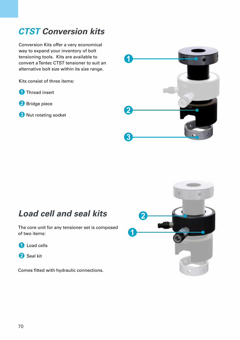
70
CTST Conversion kitsConversion Kits offer a very economical way to expand your inventory of bolt tensioning tools. Kits are available to convert a Tentec CTST tensioner to suit an alternative bolt size within its size range.
Kits consist of three items:
1 Thread insert
2 Bridge piece
3 Nut rotating socket
Load cell and seal kitsThe core unit for any tensioner set is composed of two items:
Comes fitted with hydraulic connections.
1
2
3
1
2
Load cells Seal kit
1
2
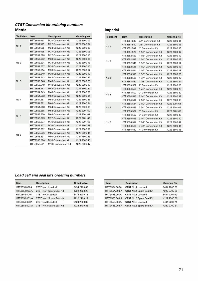
71
CTST Conversion kitsTool Ident Item Description Ordering No.
No 1
HTT.9551.536 3/4" Conversion Kit 4222 2600 01
HTT.9551.580 7/8" Conversion Kit 4222 2600 03
HTT.9551.502 1" Conversion Kit 4222 2600 05
HTT.9551.520 1 1/8" Conversion Kit 4222 2600 07
No 2
HTT.9552.520 1 1/8" Conversion Kit 4222 2600 12
HTT.9552.516 1 1/4" Conversion Kit 4222 2600 09
HTT.9552.540 1 3/8" Conversion Kit 4222 2600 14
HTT.9552.511 1 1/2" Conversion Kit 4222 2600 16
No 3
HTT.9553.514 1 1/2" Conversion Kit 4222 2600 18
HTT.9553.516 1 5/8" Conversion Kit 4222 2600 20
HTT.9553.536 1 3/4" Conversion Kit 4222 2600 22
HTT.9553.580 1 7/8" Conversion Kit 4222 2600 24
HTT.9553.502 2" Conversion Kit 4222 2600 26
No 4
HTT.9554.580 1 7/8" Conversion Kit 4222 2600 28
HTT.9554.502 2" Conversion Kit 4222 2600 30
HTT.9554.516 2 1/4" Conversion Kit 4222 2600 32
HTT.9554.511 2 1/2" Conversion Kit 4222 2600 35
No 5
HTT.9555.514 2 1/2" Conversion Kit 4222 2701 64
HTT.9555.536 2 3/4" Conversion Kit 4222 2701 65
HTT.9555.502 3" Conversion Kit 4222 2701 66
No 6
HTT.9556.502 3" Conversion Kit 4222 2600 37
HTT.9556.516 3 1/4" Conversion Kit 4222 2600 40
HTT.9556.511 3 1/2" Conversion Kit 4222 2600 42
HTT.9556.536 3 3/4" Conversion Kit 4222 2600 44
HTT.9556.542 4" Conversion Kit 4222 2600 46
CTST Conversion kit ordering numbers
Item Description Ordering No.
HTT.9551.000A CTST No.1 Loadcell 8434 2200 69
HTT.9551.003.A CTST No.1 Spare Seal Kit 4222 2700 26
HTT.9552.000A CTST No.2 Loadcell 8434 2200 78
HTT.9552.003.A CTST No.2 Spare Seal Kit 4222 2700 27
HTT.9553.000A CTST No.3 Loadcell 8434 2200 88
HTT.9553.003.A CTST No.3 Spare Seal Kit 4222 2700 28
Item Description Ordering No.
HTT.9554.000A CTST No.4 Loadcell 8434 2200 99
HTT.9554.003.A CTST No.4 Spare Seal Kit 4222 2700 29
HTT.9555.000A CTST No.5 Loadcell 8434 2201 09
HTT.9555.003.A CTST No.5 Spare Seal Kit 4222 2700 30
HTT.9556.000A CTST No.6 Loadcell 8434 2201 24
HTT.9556.003.A CTST No.6 Spare Seal Kit 4222 2700 31
Load cell and seal kits ordering numbers
Tool Ident Item Description Ordering No.
No 1
HTT.9551.521 M20 Conversion Kit 4222 2600 02
HTT.9551.523 M22 Conversion Kit 4222 2600 04
HTT.9551.525 M24 Conversion Kit 4222 2600 06
HTT.9551.528 M27 Conversion Kit 4222 2600 08
No 2
HTT.9552.528 M27 Conversion Kit 4222 2600 10
HTT.9552.532 M30 Conversion Kit 4222 2600 11
HTT.9552.534 M33 Conversion Kit 4222 2600 13
HTT.9552.537 M36 Conversion Kit 4222 2600 15
HTT.9552.514 M39 Conversion Kit 4222 2600 17
No 3
HTT.9553.540 M39 Conversion Kit 4222 2600 19
HTT.9553.543 M42 Conversion Kit 4222 2600 21
HTT.9553.546 M45 Conversion Kit 4222 2600 23
HTT.9553.549 M48 Conversion Kit 4222 2600 25
HTT.9553.553 M52 Conversion Kit 4222 2600 27
No 4
HTT.9554.549 M48 Conversion Kit 4222 2600 29
HTT.9554.553 M52 Conversion Kit 4222 2600 31
HTT.9554.557 M56 Conversion Kit 4222 2600 33
HTT.9554.562 M60 Conversion Kit 4222 2600 34
HTT.9554.568 M64 Conversion Kit 4222 2600 36
No 5
HTT.9555.565 M64 Conversion Kit 4222 2701 60
HTT.9555.570 M68 Conversion Kit 4222 2701 61
HTT.9555.573 M72 Conversion Kit 4222 2701 62
HTT.9555.577 M76 Conversion Kit 4222 2701 63
No 6
HTT.9556.577 M76 Conversion Kit 4222 2600 38
HTT.9556.582 M80 Conversion Kit 4222 2600 39
HTT.9556.586 M85 Conversion Kit 4222 2600 41
HTT.9556.591 M90 Conversion Kit 4222 2600 43
HTT.9556.596 M95 Conversion Kit 4222 2600 45
HTT.9556.501 M100 Conversion Kit 4222 2600 47
Metric Imperial
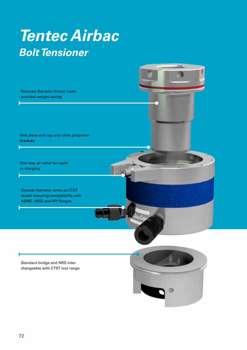
72
One way air valve for rapid re-charging
Outside diameter same as CTST model ensuring compatibility with ASME, ANSI and API flanges
Standard bridge and NRS inter-changeable with CTST tool range
Reduced diameter thread insert provides weight saving
One piece end cap and valve protection brackets
Tentec AirbacBolt Tensioner
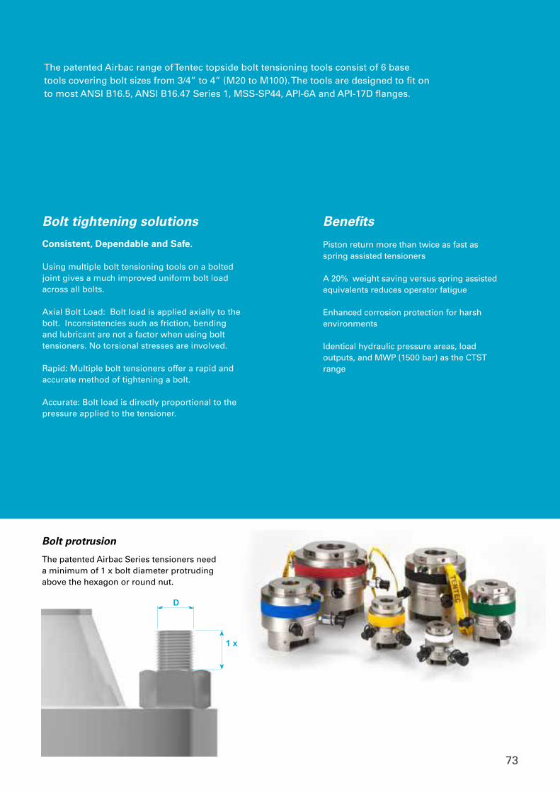
73
Piston return more than twice as fast as spring assisted tensioners
A 20% weight saving versus spring assisted equivalents reduces operator fatigue
Enhanced corrosion protection for harsh environments
Identical hydraulic pressure areas, load outputs, and MWP (1500 bar) as the CTST range
D
1 x Dmin
Bolt protrusion
The patented Airbac Series tensioners need a minimum of 1 x bolt diameter protruding above the hexagon or round nut.
Bolt tightening solutions
Consistent, Dependable and Safe.
Using multiple bolt tensioning tools on a bolted joint gives a much improved uniform bolt load across all bolts.
Axial Bolt Load: Bolt load is applied axially to the bolt. Inconsistencies such as friction, bending and lubricant are not a factor when using bolt tensioners. No torsional stresses are involved.
Rapid: Multiple bolt tensioners offer a rapid and accurate method of tightening a bolt.
Accurate: Bolt load is directly proportional to the pressure applied to the tensioner.
The patented Airbac range of Tentec topside bolt tensioning tools consist of 6 base tools covering bolt sizes from 3/4” to 4” (M20 to M100). The tools are designed to fit on to most ANSI B16.5, ANSI B16.47 Series 1, MSS-SP44, API-6A and API-17D flanges.
Tentec CTSTTensioner Datasheet
Benefits
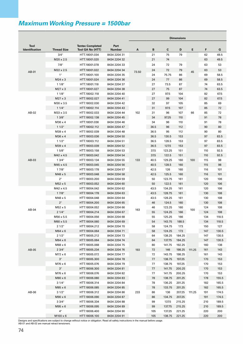
74
Tool Identification Thread Size
Tentec Completed Tool GA No (HTT)
Part Number
Dimensions
A B C D E F G
AB-01
3/4" HTT.18001.034 8434 2204 31
73.50
21 75 79
45
62 49.5
M20 x 2.5 HTT.18001.020 8434 2204 32 21 74 63 49.5
7/8" HTT.18001.078 8434 2204 33 24 72 79 63 53
M22 x 2.5 HTT.18001.022 8434 2204 34 24 72 79 63 53
1" HTT.18001.100 8434 2204 35 24 75.75 86 69 58.5
M24 x 3 HTT.18001.024 8434 2204 36 24 77 86 69 58.5
1 1/8" HTT.18001.118 8434 2204 37 27 73.5 87 74 63.5
M27 x 3 HTT.18001.027 8434 2204 38 27 75 87 74 63.5
AB-02
1 1/8" HTT.18002.118 8434 2204 40
102
27 97.5 104
66
82 67.5
M27 x 3 HTT.18002.027 8434 2204 41 27 99 104 82 67.5
M30 x 3.5 HTT.18002.030 8434 2204 42 32 97 105 85 69
1 1/4" HTT.18002.114 8434 2204 43 31 97.5 107 85 72
M33 x 3.5 HTT.18002.033 8434 2204 44 31 96 107 85 72
1 3/8" HTT.18002.138 8434 2204 45 34 97.25 110 91 78
M36 x 4 HTT.18001.036 8434 2204 46 34 96 110 91 78
1 1/2" HTT.18002.112 8434 2204 47 36.5 96 112 90 80
M39 x 4 HTT.18002.039 8434 2204 48 36.5 95 112 90 80
AB-03
M36 x 4 HTT.18003.036 8434 2204 50
133
36.5 130.5 153
100
97 83.5
1 1/2" HTT.18003.112 8434 2204 51 36.5 128.5 153 97 83.5
M39 x 4 HTT.18003.039 8434 2204 52 36.5 127.5 153 97 83.5
1 5/8" HTT.18003.158 8434 2204 53 37.5 123.25 151 110 92.5
M42 x 4.5 HTT.18003.042 8434 2204 54 37.5 122.5 151 110 92.5
1 3/4" HTT.18003.134 8434 2204 55 40.5 129.25 160 115 98
M45 x 4.5 HTT.18003.045 8434 2204 56 40.5 128.5 160 115 98
1 7/8" HTT.18003.178 8434 2204 57 42.5 126 160 116 101
M48 x 5 HTT.18003.048 8434 2204 58 42.5 125.5 160 116 101
2" HTT.18003.200 8434 2204 59 50 123.75 161 120 106
M52 x 5 HTT.18003.052 8434 2204 60 50 122.5 161 120 106
AB-04
M42 x 4.5 HTT.18004.042 8434 2204 62
163
43.5 134.25 161
100
120 106
1 7/8" HTT.18004.178 8434 2204 63 43.5 128.75 161 130 108
M48 x 5 HTT.18004.048 8434 2204 64 43.5 128.25 161 130 108
2" HTT.18004.200 8434 2204 65 46 124.5 160 130 108
M52 x 5 HTT.18004.052 8434 2204 66 46 123.25 160 124 108
2 1/4" HTT.18004.214 8434 2204 67 55 124.25 166 124 108
M56 x 5.5 HTT.18004.056 8434 2204 68 55 125.25 166 134 118.5
M60 x 5.5 HTT.18004.060 8434 2204 69 54 143.75 188.5 134 118.5
2 1/2" HTT.18004.212 8434 2204 70 58 124.75 173 150 127
M64 x 6 HTT.18004.064 8434 2204 71 58 124.25 173 147 130.5
AB-05
2 1/2" HTT.18005.212 8434 2204 73
193
64 138.25 184.25
111.25
147 130.5
M64 x 6 HTT.18005.064 8434 2204 74 64 137.75 184.25 147 130.5
M68 x 6 HTT.18005.068 8434 2204 75 80 141.75 192.25 160 138
2 3/4" HTT.18005.234 8434 2204 76 72 146 198.25 161 143
M72 x 6 HTT.18005.072 8434 2204 77 72 143.75 198.25 161 143
3" HTT.18005.300 8434 2204 78 77 138.75 197.25 170 153
M76 x 6 HTT.18005.076 8434 2204 79 77 138.75 197.25 170 153
AB-06
3" HTT.18006.300 8434 2204 81
233
77 141.75 200.25
111.25
170 153
M76 x 6 HTT.18006.076 8434 2204 82 77 141.75 200.25 170 153
M80 x 6 HTT.18006.080 8434 2204 83 78 138.75 201.25 178 155.5
3 1/4" HTT.18006.314 8434 2204 84 78 136.25 201.25 182 165.5
M85 x 6 HTT.18006.085 8434 2204 85 78 133.75 201.25 182 165.5
3 1/2" HTT.18006.312 8434 2204 86 86 136 207.25 191 174.5
M90 x 6 HTT.18006.090 8434 2204 87 86 134.75 207.25 191 174.5
3 3/4" HTT.18006.334 8434 2204 88 99 137.5 215.25 210 189.5
M95 x 6 HTT.18006.095 8434 2204 89 99 137.75 215.25 210 189.5
4" HTT.18006.400 8434 2204 90 105 137.25 221.25 220 200
M100 x 6 HTT.18006.100 8434 2204 91 105 138.75 221.25 220 200
Maximum Working Pressure = 1500bar
Designs and specifications are subject to change without notice or obligation. Read all safety instructions in the manual before usage.AB-01 and AB-02 are manual retract tensioners.
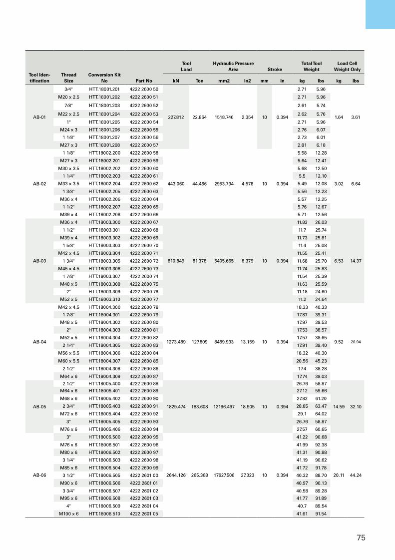
75
Tool Iden-tification
Thread Size
Conversion Kit No Part No
Tool Load
Hydraulic Pressure Area Stroke
Total ToolWeight
Load Cell Weight Only
kN Ton mm2 In2 mm In kg lbs kg lbs
AB-01
3/4" HTT.18001.201 4222 2600 50
227.812 22.864 1518.746 2.354 10 0.394
2.71 5.96
1.64 3.61
M20 x 2.5 HTT.18001.202 4222 2600 51 2.71 5.96
7/8" HTT.18001.203 4222 2600 52 2.61 5.74
M22 x 2.5 HTT.18001.204 4222 2600 53 2.62 5.76
1" HTT.18001.205 4222 2600 54 2.71 5.96
M24 x 3 HTT.18001.206 4222 2600 55 2.76 6.07
1 1/8" HTT.18001.207 4222 2600 56 2.73 6.01
M27 x 3 HTT.18001.208 4222 2600 57 2.81 6.18
AB-02
1 1/8" HTT.18002.200 4222 2600 58
443.060 44.466 2953.734 4.578 10 0.394
5.58 12.28
3.02 6.64
M27 x 3 HTT.18002.201 4222 2600 59 5.64 12.41
M30 x 3.5 HTT.18002.202 4222 2600 60 5.68 12.50
1 1/4" HTT.18002.203 4222 2600 61 5.5 12.10
M33 x 3.5 HTT.18002.204 4222 2600 62 5.49 12.08
1 3/8" HTT.18002.205 4222 2600 63 5.56 12.23
M36 x 4 HTT.18002.206 4222 2600 64 5.57 12.25
1 1/2" HTT.18002.207 4222 2600 65 5.76 12.67
M39 x 4 HTT.18002.208 4222 2600 66 5.71 12.56
AB-03
M36 x 4 HTT.18003.300 4222 2600 67
810.849 81.378 5405.665 8.379 10 0.394
11.83 26.03
6.53 14.37
1 1/2" HTT.18003.301 4222 2600 68 11.7 25.74
M39 x 4 HTT.18003.302 4222 2600 69 11.73 25.81
1 5/8" HTT.18003.303 4222 2600 70 11.4 25.08
M42 x 4.5 HTT.18003.304 4222 2600 71 11.55 25.41
1 3/4" HTT.18003.305 4222 2600 72 11.68 25.70
M45 x 4.5 HTT.18003.306 4222 2600 73 11.74 25.83
1 7/8" HTT.18003.307 4222 2600 74 11.54 25.39
M48 x 5 HTT.18003.308 4222 2600 75 11.63 25.59
2" HTT.18003.309 4222 2600 76 11.18 24.60
M52 x 5 HTT.18003.310 4222 2600 77 11.2 24.64
AB-04
M42 x 4.5 HTT.18004.300 4222 2600 78
1273.489 127.809 8489.933 13.159 10 0.394
18.33 40.33
9.52 20.94
1 7/8" HTT.18004.301 4222 2600 79 17.87 39.31
M48 x 5 HTT.18004.302 4222 2600 80 17.97 39.53
2" HTT.18004.303 4222 2600 81 17.53 38.57
M52 x 5 HTT.18004.304 4222 2600 82 17.57 38.65
2 1/4" HTT.18004.305 4222 2600 83 17.91 39.40
M56 x 5.5 HTT.18004.306 4222 2600 84 18.32 40.30
M60 x 5.5 HTT.18004.307 4222 2600 85 20.56 45.23
2 1/2" HTT.18004.308 4222 2600 86 17.4 38.28
M64 x 6 HTT.18004.309 4222 2600 87 17.74 39.03
AB-05
2 1/2" HTT.18005.400 4222 2600 88
1829.474 183.608 12196.497 18.905 10 0.394
26.76 58.87
14.59 32.10
M64 x 6 HTT.18005.401 4222 2600 89 27.12 59.66
M68 x 6 HTT.18005.402 4222 2600 90 27.82 61.20
2 3/4" HTT.18005.403 4222 2600 91 28.85 63.47
M72 x 6 HTT.18005.404 4222 2600 92 29.1 64.02
3" HTT.18005.405 4222 2600 93 26.76 58.87
M76 x 6 HTT.18005.406 4222 2600 94 27.57 60.65
AB-06
3" HTT.18006.500 4222 2600 95
2644.126 265.368 17627.506 27.323 10 0.394
41.22 90.68
20.11 44.24
M76 x 6 HTT.18006.501 4222 2600 96 41.99 92.38
M80 x 6 HTT.18006.502 4222 2600 97 41.31 90.88
3 1/4" HTT.18006.503 4222 2600 98 41.19 90.62
M85 x 6 HTT.18006.504 4222 2600 99 41.72 91.78
3 1/2" HTT.18006.505 4222 2601 00 40.32 88.70
M90 x 6 HTT.18006.506 4222 2601 01 40.97 90.13
3 3/4" HTT.18006.507 4222 2601 02 40.58 89.28
M95 x 6 HTT.18006.508 4222 2601 03 41.77 91.89
4" HTT.18006.509 4222 2601 04 40.7 89.54
M100 x 6 HTT.18006.510 4222 2601 05 41.61 91.54
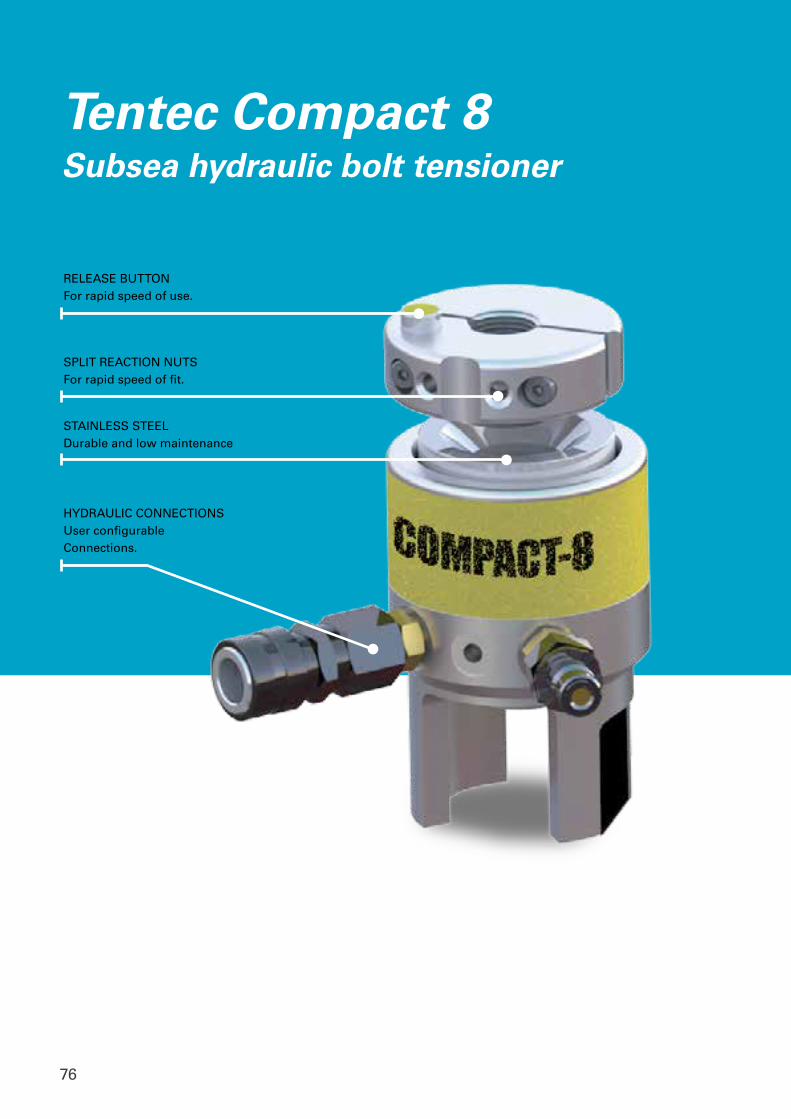
76
SPLIT REACTION NUTSFor rapid speed of fit.
RELEASE BUTTONFor rapid speed of use.
HYDRAULIC CONNECTIONSUser configurableConnections.
Tentec Compact 8Subsea hydraulic bolt tensioner
STAINLESS STEELDurable and low maintenance
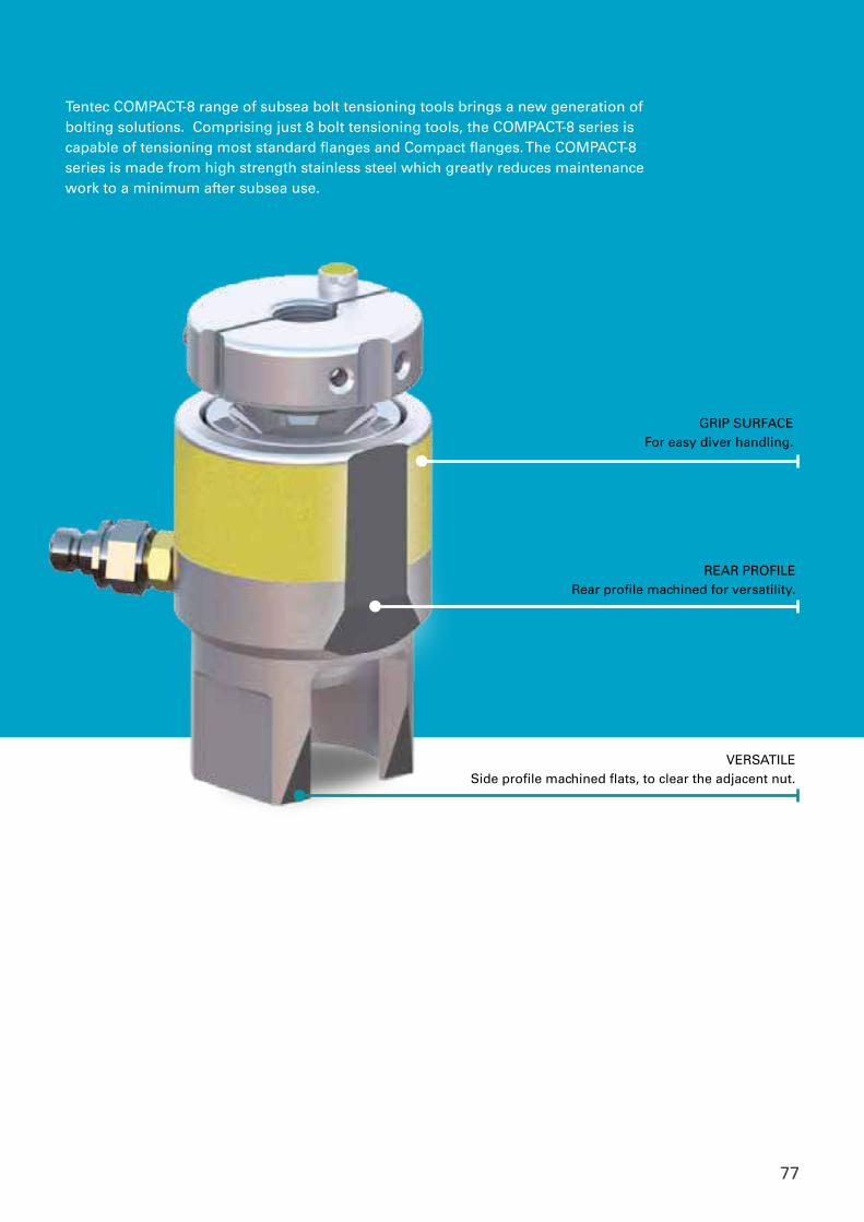
77
VERSATILESide profile machined flats, to clear the adjacent nut.
REAR PROFILERear profile machined for versatility.
GRIP SURFACEFor easy diver handling.
Tentec COMPACT-8 range of subsea bolt tensioning tools brings a new generation of bolting solutions. Comprising just 8 bolt tensioning tools, the COMPACT-8 series is capable of tensioning most standard flanges and Compact flanges. The COMPACT-8 series is made from high strength stainless steel which greatly reduces maintenance work to a minimum after subsea use.
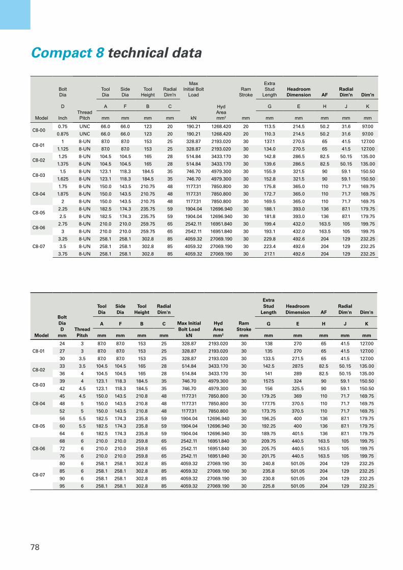
78
Model
Bolt Dia
Thread Pitch
Tool Dia
Side Dia
Tool Height
Radial Dim'n
Max Initial Bolt
Load
HydAreamm2
Ram Stroke
Extra Stud
LengthHeadroom Dimension AF
Radial Dim'n Dim'n
D A F B C G E H J K
Inch mm mm mm mm kN mm mm mm mm mm mm
C8-000.75 UNC 66.0 66.0 123 20 190.21 1268.420 20 113.5 214.5 50.2 31.6 97.00
0.875 UNC 66.0 66.0 123 20 190.21 1268.420 20 110.3 214.5 50.2 31.6 97.00
C8-011 8-UN 87.0 87.0 153 25 328.87 2193.020 30 137.1 270.5 65 41.5 127.00
1.125 8-UN 87.0 87.0 153 25 328.87 2193.020 30 134.0 270.5 65 41.5 127.00
C8-021.25 8-UN 104.5 104.5 165 28 514.84 3433.170 30 142.8 286.5 82.5 50.15 135.00
1.375 8-UN 104.5 104.5 165 28 514.84 3433.170 30 139.6 286.5 82.5 50.15 135.00
C8-031.5 8-UN 123.1 118.3 184.5 35 746.70 4979.300 30 155.9 321.5 90 59.1 150.50
1.625 8-UN 123.1 118.3 184.5 35 746.70 4979.300 30 152.8 321.5 90 59.1 150.50
C8-04
1.75 8-UN 150.0 143.5 210.75 48 1177.31 7850.800 30 175.8 365.0 110 71.7 169.75
1.875 8-UN 150.0 143.5 210.75 48 1177.31 7850.800 30 172.7 365.0 110 71.7 169.75
2 8-UN 150.0 143.5 210.75 48 1177.31 7850.800 30 169.5 365.0 110 71.7 169.75
C8-052.25 8-UN 182.5 174.3 235.75 59 1904.04 12696.940 30 188.1 393.0 136 87.1 179.75
2.5 8-UN 182.5 174.3 235.75 59 1904.04 12696.940 30 181.8 393.0 136 87.1 179.75
C8-062.75 8-UN 210.0 210.0 259.75 65 2542.11 16951.840 30 199.4 432.0 163.5 105 199.75
3 8-UN 210.0 210.0 259.75 65 2542.11 16951.840 30 193.1 432.0 163.5 105 199.75
C8-07
3.25 8-UN 258.1 258.1 302.8 85 4059.32 27069.190 30 229.8 492.6 204 129 232.25
3.5 8-UN 258.1 258.1 302.8 85 4059.32 27069.190 30 223.4 492.6 204 129 232.25
3.75 8-UN 258.1 258.1 302.8 85 4059.32 27069.190 30 217.1 492.6 204 129 232.25
Compact 8 technical data
Model
Bolt DiaD
mmThread Pitch
Tool Dia
Side Dia
Tool Height
Radial Dim'n
Max Initial Bolt Load
kN
HydAreamm2
Ram Stroke
mm
Extra Stud
LengthHeadroom Dimension AF
Radial Dim'n Dim'n
A F B C G E H J K
mm mm mm mm mm mm mm mm mm
C8-01
24 3 87.0 87.0 153 25 328.87 2193.020 30 138 270 65 41.5 127.00
27 3 87.0 87.0 153 25 328.87 2193.020 30 135 270 65 41.5 127.00
30 3.5 87.0 87.0 153 25 328.87 2193.020 30 133.5 271.5 65 41.5 127.00
C8-0233 3.5 104.5 104.5 165 28 514.84 3433.170 30 142.5 287.5 82.5 50.15 135.00
36 4 104.5 104.5 165 28 514.84 3433.170 30 141 289 82.5 50.15 135.00
C8-0339 4 123.1 118.3 184.5 35 746.70 4979.300 30 157.5 324 90 59.1 150.50
42 4.5 123.1 118.3 184.5 35 746.70 4979.300 30 156 325.5 90 59.1 150.50
C8-04
45 4.5 150.0 143.5 210.8 48 1177.31 7850.800 30 179.25 369 110 71.7 169.75
48 5 150.0 143.5 210.8 48 1177.31 7850.800 30 177.75 370.5 110 71.7 169.75
52 5 150.0 143.5 210.8 48 1177.31 7850.800 30 173.75 370.5 110 71.7 169.75
C8-05
56 5.5 182.5 174.3 235.8 59 1904.04 12696.940 30 196.25 400 136 87.1 179.75
60 5.5 182.5 174.3 235.8 59 1904.04 12696.940 30 192.25 400 136 87.1 179.75
64 6 182.5 174.3 235.8 59 1904.04 12696.940 30 189.75 401.5 136 87.1 179.75
C8-06
68 6 210.0 210.0 259.8 65 2542.11 16951.840 30 209.75 440.5 163.5 105 199.75
72 6 210.0 210.0 259.8 65 2542.11 16951.840 30 205.75 440.5 163.5 105 199.75
76 6 210.0 210.0 259.8 65 2542.11 16951.840 30 201.75 440.5 163.5 105 199.75
C8-07
80 6 258.1 258.1 302.8 85 4059.32 27069.190 30 240.8 501.05 204 129 232.25
85 6 258.1 258.1 302.8 85 4059.32 27069.190 30 235.8 501.05 204 129 232.25
90 6 258.1 258.1 302.8 85 4059.32 27069.190 30 230.8 501.05 204 129 232.25
95 6 258.1 258.1 302.8 85 4059.32 27069.190 30 225.8 501.05 204 129 232.25
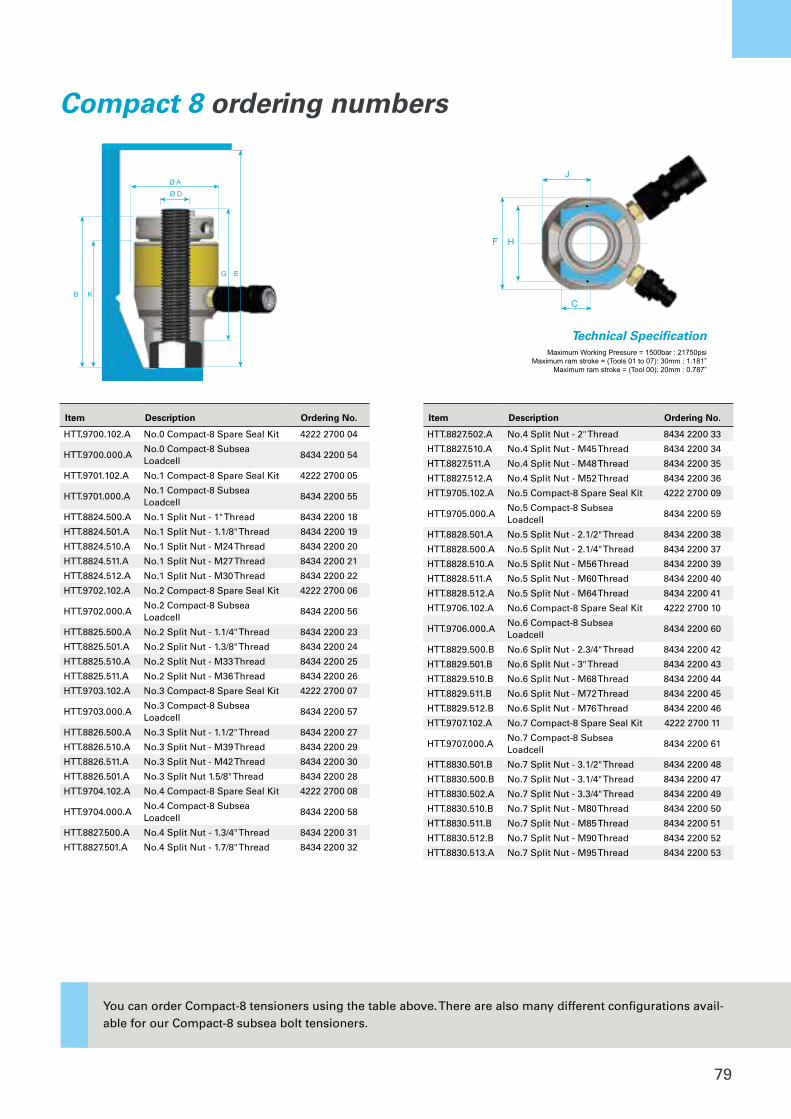
79
Bolt Dia
Thread
Pitch
Tool
Dia
Effective
Side
Diameter
Tool
Height
Radial
Dim'n
Max Initial
Bolt Load
Hydraulic
Area
Ram
Stroke
Extra Stud
Length
(Inc
3xPitches
extra)
Headroom
Dimension
Across
Flats
Radial
Dim'n
Dim'n
D A F B C G E H J K
Inch mm mm mm mm kN mm2 mm mm mm mm mm mm
0.75 UNC 66.0 66.0 123 20 190.21 1268.420 20 113.5 214.5 50.2 31.6 97.00
0.875 UNC 66.0 66.0 123 20 190.21 1268.420 20 110.3 214.5 50.2 31.6 97.00
1 8-UN 87.0 87.0 153 25 328.87 2193.020 30 137.1 270.5 65 41.5 127.00
1.125 8-UN 87.0 87.0 153 25 328.87 2193.020 30 134.0 270.5 65 41.5 127.00
1.25 8-UN 104.5 104.5 165 28 514.84 3433.170 30 142.8 286.5 82.5 50.15 135.00
1.375 8-UN 104.5 104.5 165 28 514.84 3433.170 30 139.6 286.5 82.5 50.15 135.00
1.5 8-UN 123.1 118.3 184.5 35 746.70 4979.300 30 155.9 321.5 90 59.1 150.50
1.625 8-UN 123.1 118.3 184.5 35 746.70 4979.300 30 152.8 321.5 90 59.1 150.50
1.75 8-UN 150.0 143.5 210.75 48 1177.31 7850.800 30 175.8 365.0 110 71.7 169.75
1.875 8-UN 150.0 143.5 210.75 48 1177.31 7850.800 30 172.7 365.0 110 71.7 169.75
2 8-UN 150.0 143.5 210.75 48 1177.31 7850.800 30 169.5 365.0 110 71.7 169.75
2.25 8-UN 182.5 174.3 235.75 59 1904.04 12696.940 30 188.1 393.0 136 87.1 179.75
2.5 8-UN 182.5 174.3 235.75 59 1904.04 12696.940 30 181.8 393.0 136 87.1 179.75
2.75 8-UN 210.0 210.0 259.75 65 2542.11 16951.840 30 199.4 432.0 163.5 105 199.75
3 8-UN 210.0 210.0 259.75 65 2542.11 16951.840 30 193.1 432.0 163.5 105 199.75
3.25 8-UN 258.1 258.1 302.8 85 4059.32 27069.190 30 229.8 492.6 204 129 232.25
3.5 8-UN 258.1 258.1 302.8 85 4059.32 27069.190 30 223.4 492.6 204 129 232.25
3.75 8-UN 258.1 258.1 302.8 85 4059.32 27069.190 30 217.1 492.6 204 129 232.25
Bolt Dia
Thread
Pitch
Tool
Dia
Effective
Side
Diameter
Tool
Height
Radial
Dim'n
Max Initial
Bolt Load
Hydraulic
Area
Ram
Stroke
Extra Stud
Length
(Including
3xPitches
extra)
Headroom
Dimension
Across
Flats
Radial
Dim'n
Dim'n
D A F B C G E H J K
Metric mm mm mm mm kN mm2 mm mm mm mm mm mm
20 2.5 66.0 66.0 123 20 190.21 1268.420 20 110.5 212.5 50.2 31.6 97.00
22 2.5 66.0 66.0 123 20 190.21 1268.420 20 108.5 212.5 50.2 31.6 97.00
24 3 87.0 87.0 153 25 328.87 2193.020 30 138 270 65 41.5 127.00
27 3 87.0 87.0 153 25 328.87 2193.020 30 135 270 65 41.5 127.00
30 3.5 87.0 87.0 153 25 328.87 2193.020 30 133.5 271.5 65 41.5 127.00
33 3.5 104.5 104.5 165 28 514.84 3433.170 30 142.5 287.5 82.5 50.15 135.00
36 4 104.5 104.5 165 28 514.84 3433.170 30 141 289 82.5 50.15 135.00
39 4 123.1 118.3 184.5 35 746.70 4979.300 30 157.5 324 90 59.1 150.50
42 4.5 123.1 118.3 184.5 35 746.70 4979.300 30 156 325.5 90 59.1 150.50
45 4.5 150.0 143.5 210.8 48 1177.31 7850.800 30 179.25 369 110 71.7 169.75
48 5 150.0 143.5 210.8 48 1177.31 7850.800 30 177.75 370.5 110 71.7 169.75
52 5 150.0 143.5 210.8 48 1177.31 7850.800 30 173.75 370.5 110 71.7 169.75
56 5.5 182.5 174.3 235.8 59 1904.04 12696.940 30 196.25 400 136 87.1 179.75
60 5.5 182.5 174.3 235.8 59 1904.04 12696.940 30 192.25 400 136 87.1 179.75
64 6 182.5 174.3 235.8 59 1904.04 12696.940 30 189.75 401.5 136 87.1 179.75
68 6 210.0 210.0 259.8 65 2542.11 16951.840 30 209.75 440.5 163.5 105 199.75
72 6 210.0 210.0 259.8 65 2542.11 16951.840 30 205.75 440.5 163.5 105 199.75
76 6 210.0 210.0 259.8 65 2542.11 16951.840 30 201.75 440.5 163.5 105 199.75
80 6 258.1 258.1 302.8 85 4059.32 27069.190 30 240.8 501.05 204 129 232.25
85 6 258.1 258.1 302.8 85 4059.32 27069.190 30 235.8 501.05 204 129 232.25
90 6 258.1 258.1 302.8 85 4059.32 27069.190 30 230.8 501.05 204 129 232.25
95 6 258.1 258.1 302.8 85 4059.32 27069.190 30 225.8 501.05 204 129 232.25
C8-05
C8-06
C8-00
C8-01
C8-02
C8-04
C8-03
C8-07
C8-07
C8-00
C8-01
C8-02
C8-03
C8-04
C8-05
C8-06
Bolt Dia
Thread
Pitch
Tool
Dia
Effective
Side
Diameter
Tool
Height
Radial
Dim'n
Max Initial
Bolt Load
Hydraulic
Area
Ram
Stroke
Extra Stud
Length
(Inc
3xPitches
extra)
Headroom
Dimension
Across
Flats
Radial
Dim'n
Dim'n
D A F B C G E H J K
Inch mm mm mm mm kN mm2 mm mm mm mm mm mm
0.75 UNC 66.0 66.0 123 20 190.21 1268.420 20 113.5 214.5 50.2 31.6 97.00
0.875 UNC 66.0 66.0 123 20 190.21 1268.420 20 110.3 214.5 50.2 31.6 97.00
1 8-UN 87.0 87.0 153 25 328.87 2193.020 30 137.1 270.5 65 41.5 127.00
1.125 8-UN 87.0 87.0 153 25 328.87 2193.020 30 134.0 270.5 65 41.5 127.00
1.25 8-UN 104.5 104.5 165 28 514.84 3433.170 30 142.8 286.5 82.5 50.15 135.00
1.375 8-UN 104.5 104.5 165 28 514.84 3433.170 30 139.6 286.5 82.5 50.15 135.00
1.5 8-UN 123.1 118.3 184.5 35 746.70 4979.300 30 155.9 321.5 90 59.1 150.50
1.625 8-UN 123.1 118.3 184.5 35 746.70 4979.300 30 152.8 321.5 90 59.1 150.50
1.75 8-UN 150.0 143.5 210.75 48 1177.31 7850.800 30 175.8 365.0 110 71.7 169.75
1.875 8-UN 150.0 143.5 210.75 48 1177.31 7850.800 30 172.7 365.0 110 71.7 169.75
2 8-UN 150.0 143.5 210.75 48 1177.31 7850.800 30 169.5 365.0 110 71.7 169.75
2.25 8-UN 182.5 174.3 235.75 59 1904.04 12696.940 30 188.1 393.0 136 87.1 179.75
2.5 8-UN 182.5 174.3 235.75 59 1904.04 12696.940 30 181.8 393.0 136 87.1 179.75
2.75 8-UN 210.0 210.0 259.75 65 2542.11 16951.840 30 199.4 432.0 163.5 105 199.75
3 8-UN 210.0 210.0 259.75 65 2542.11 16951.840 30 193.1 432.0 163.5 105 199.75
3.25 8-UN 258.1 258.1 302.8 85 4059.32 27069.190 30 229.8 492.6 204 129 232.25
3.5 8-UN 258.1 258.1 302.8 85 4059.32 27069.190 30 223.4 492.6 204 129 232.25
3.75 8-UN 258.1 258.1 302.8 85 4059.32 27069.190 30 217.1 492.6 204 129 232.25
Bolt Dia
Thread
Pitch
Tool
Dia
Effective
Side
Diameter
Tool
Height
Radial
Dim'n
Max Initial
Bolt Load
Hydraulic
Area
Ram
Stroke
Extra Stud
Length
(Including
3xPitches
extra)
Headroom
Dimension
Across
Flats
Radial
Dim'n
Dim'n
D A F B C G E H J K
Metric mm mm mm mm kN mm2 mm mm mm mm mm mm
20 2.5 66.0 66.0 123 20 190.21 1268.420 20 110.5 212.5 50.2 31.6 97.00
22 2.5 66.0 66.0 123 20 190.21 1268.420 20 108.5 212.5 50.2 31.6 97.00
24 3 87.0 87.0 153 25 328.87 2193.020 30 138 270 65 41.5 127.00
27 3 87.0 87.0 153 25 328.87 2193.020 30 135 270 65 41.5 127.00
30 3.5 87.0 87.0 153 25 328.87 2193.020 30 133.5 271.5 65 41.5 127.00
33 3.5 104.5 104.5 165 28 514.84 3433.170 30 142.5 287.5 82.5 50.15 135.00
36 4 104.5 104.5 165 28 514.84 3433.170 30 141 289 82.5 50.15 135.00
39 4 123.1 118.3 184.5 35 746.70 4979.300 30 157.5 324 90 59.1 150.50
42 4.5 123.1 118.3 184.5 35 746.70 4979.300 30 156 325.5 90 59.1 150.50
45 4.5 150.0 143.5 210.8 48 1177.31 7850.800 30 179.25 369 110 71.7 169.75
48 5 150.0 143.5 210.8 48 1177.31 7850.800 30 177.75 370.5 110 71.7 169.75
52 5 150.0 143.5 210.8 48 1177.31 7850.800 30 173.75 370.5 110 71.7 169.75
56 5.5 182.5 174.3 235.8 59 1904.04 12696.940 30 196.25 400 136 87.1 179.75
60 5.5 182.5 174.3 235.8 59 1904.04 12696.940 30 192.25 400 136 87.1 179.75
64 6 182.5 174.3 235.8 59 1904.04 12696.940 30 189.75 401.5 136 87.1 179.75
68 6 210.0 210.0 259.8 65 2542.11 16951.840 30 209.75 440.5 163.5 105 199.75
72 6 210.0 210.0 259.8 65 2542.11 16951.840 30 205.75 440.5 163.5 105 199.75
76 6 210.0 210.0 259.8 65 2542.11 16951.840 30 201.75 440.5 163.5 105 199.75
80 6 258.1 258.1 302.8 85 4059.32 27069.190 30 240.8 501.05 204 129 232.25
85 6 258.1 258.1 302.8 85 4059.32 27069.190 30 235.8 501.05 204 129 232.25
90 6 258.1 258.1 302.8 85 4059.32 27069.190 30 230.8 501.05 204 129 232.25
95 6 258.1 258.1 302.8 85 4059.32 27069.190 30 225.8 501.05 204 129 232.25
C8-05
C8-06
C8-00
C8-01
C8-02
C8-04
C8-03
C8-07
C8-07
C8-00
C8-01
C8-02
C8-03
C8-04
C8-05
C8-06
Technical Specification
Metric Threads
Inch Threads
Maximum Working Pressure = 1500bar : 21750psiMaximum ram stroke = (Tools 01 to 07): 30mm : 1.181”
Maximum ram stroke = (Tool 00): 20mm : 0.787”
C
HF
JØ AØ D
KB B
EG
Designs and specifications are subject to change without notice or obligation. Read all safety instructions in the manual before usage.
Bolt Dia
Thread
Pitch
Tool
Dia
Effective
Side
Diameter
Tool
Height
Radial
Dim'n
Max Initial
Bolt Load
Hydraulic
Area
Ram
Stroke
Extra Stud
Length
(Inc
3xPitches
extra)
Headroom
Dimension
Across
Flats
Radial
Dim'n
Dim'n
D A F B C G E H J K
Inch mm mm mm mm kN mm2 mm mm mm mm mm mm
0.75 UNC 66.0 66.0 123 20 190.21 1268.420 20 113.5 214.5 50.2 31.6 97.00
0.875 UNC 66.0 66.0 123 20 190.21 1268.420 20 110.3 214.5 50.2 31.6 97.00
1 8-UN 87.0 87.0 153 25 328.87 2193.020 30 137.1 270.5 65 41.5 127.00
1.125 8-UN 87.0 87.0 153 25 328.87 2193.020 30 134.0 270.5 65 41.5 127.00
1.25 8-UN 104.5 104.5 165 28 514.84 3433.170 30 142.8 286.5 82.5 50.15 135.00
1.375 8-UN 104.5 104.5 165 28 514.84 3433.170 30 139.6 286.5 82.5 50.15 135.00
1.5 8-UN 123.1 118.3 184.5 35 746.70 4979.300 30 155.9 321.5 90 59.1 150.50
1.625 8-UN 123.1 118.3 184.5 35 746.70 4979.300 30 152.8 321.5 90 59.1 150.50
1.75 8-UN 150.0 143.5 210.75 48 1177.31 7850.800 30 175.8 365.0 110 71.7 169.75
1.875 8-UN 150.0 143.5 210.75 48 1177.31 7850.800 30 172.7 365.0 110 71.7 169.75
2 8-UN 150.0 143.5 210.75 48 1177.31 7850.800 30 169.5 365.0 110 71.7 169.75
2.25 8-UN 182.5 174.3 235.75 59 1904.04 12696.940 30 188.1 393.0 136 87.1 179.75
2.5 8-UN 182.5 174.3 235.75 59 1904.04 12696.940 30 181.8 393.0 136 87.1 179.75
2.75 8-UN 210.0 210.0 259.75 65 2542.11 16951.840 30 199.4 432.0 163.5 105 199.75
3 8-UN 210.0 210.0 259.75 65 2542.11 16951.840 30 193.1 432.0 163.5 105 199.75
3.25 8-UN 258.1 258.1 302.8 85 4059.32 27069.190 30 229.8 492.6 204 129 232.25
3.5 8-UN 258.1 258.1 302.8 85 4059.32 27069.190 30 223.4 492.6 204 129 232.25
3.75 8-UN 258.1 258.1 302.8 85 4059.32 27069.190 30 217.1 492.6 204 129 232.25
Bolt Dia
Thread
Pitch
Tool
Dia
Effective
Side
Diameter
Tool
Height
Radial
Dim'n
Max Initial
Bolt Load
Hydraulic
Area
Ram
Stroke
Extra Stud
Length
(Including
3xPitches
extra)
Headroom
Dimension
Across
Flats
Radial
Dim'n
Dim'n
D A F B C G E H J K
Metric mm mm mm mm kN mm2 mm mm mm mm mm mm
20 2.5 66.0 66.0 123 20 190.21 1268.420 20 110.5 212.5 50.2 31.6 97.00
22 2.5 66.0 66.0 123 20 190.21 1268.420 20 108.5 212.5 50.2 31.6 97.00
24 3 87.0 87.0 153 25 328.87 2193.020 30 138 270 65 41.5 127.00
27 3 87.0 87.0 153 25 328.87 2193.020 30 135 270 65 41.5 127.00
30 3.5 87.0 87.0 153 25 328.87 2193.020 30 133.5 271.5 65 41.5 127.00
33 3.5 104.5 104.5 165 28 514.84 3433.170 30 142.5 287.5 82.5 50.15 135.00
36 4 104.5 104.5 165 28 514.84 3433.170 30 141 289 82.5 50.15 135.00
39 4 123.1 118.3 184.5 35 746.70 4979.300 30 157.5 324 90 59.1 150.50
42 4.5 123.1 118.3 184.5 35 746.70 4979.300 30 156 325.5 90 59.1 150.50
45 4.5 150.0 143.5 210.8 48 1177.31 7850.800 30 179.25 369 110 71.7 169.75
48 5 150.0 143.5 210.8 48 1177.31 7850.800 30 177.75 370.5 110 71.7 169.75
52 5 150.0 143.5 210.8 48 1177.31 7850.800 30 173.75 370.5 110 71.7 169.75
56 5.5 182.5 174.3 235.8 59 1904.04 12696.940 30 196.25 400 136 87.1 179.75
60 5.5 182.5 174.3 235.8 59 1904.04 12696.940 30 192.25 400 136 87.1 179.75
64 6 182.5 174.3 235.8 59 1904.04 12696.940 30 189.75 401.5 136 87.1 179.75
68 6 210.0 210.0 259.8 65 2542.11 16951.840 30 209.75 440.5 163.5 105 199.75
72 6 210.0 210.0 259.8 65 2542.11 16951.840 30 205.75 440.5 163.5 105 199.75
76 6 210.0 210.0 259.8 65 2542.11 16951.840 30 201.75 440.5 163.5 105 199.75
80 6 258.1 258.1 302.8 85 4059.32 27069.190 30 240.8 501.05 204 129 232.25
85 6 258.1 258.1 302.8 85 4059.32 27069.190 30 235.8 501.05 204 129 232.25
90 6 258.1 258.1 302.8 85 4059.32 27069.190 30 230.8 501.05 204 129 232.25
95 6 258.1 258.1 302.8 85 4059.32 27069.190 30 225.8 501.05 204 129 232.25
C8-05
C8-06
C8-00
C8-01
C8-02
C8-04
C8-03
C8-07
C8-07
C8-00
C8-01
C8-02
C8-03
C8-04
C8-05
C8-06
Bolt Dia
Thread
Pitch
Tool
Dia
Effective
Side
Diameter
Tool
Height
Radial
Dim'n
Max Initial
Bolt Load
Hydraulic
Area
Ram
Stroke
Extra Stud
Length
(Inc
3xPitches
extra)
Headroom
Dimension
Across
Flats
Radial
Dim'n
Dim'n
D A F B C G E H J K
Inch mm mm mm mm kN mm2 mm mm mm mm mm mm
0.75 UNC 66.0 66.0 123 20 190.21 1268.420 20 113.5 214.5 50.2 31.6 97.00
0.875 UNC 66.0 66.0 123 20 190.21 1268.420 20 110.3 214.5 50.2 31.6 97.00
1 8-UN 87.0 87.0 153 25 328.87 2193.020 30 137.1 270.5 65 41.5 127.00
1.125 8-UN 87.0 87.0 153 25 328.87 2193.020 30 134.0 270.5 65 41.5 127.00
1.25 8-UN 104.5 104.5 165 28 514.84 3433.170 30 142.8 286.5 82.5 50.15 135.00
1.375 8-UN 104.5 104.5 165 28 514.84 3433.170 30 139.6 286.5 82.5 50.15 135.00
1.5 8-UN 123.1 118.3 184.5 35 746.70 4979.300 30 155.9 321.5 90 59.1 150.50
1.625 8-UN 123.1 118.3 184.5 35 746.70 4979.300 30 152.8 321.5 90 59.1 150.50
1.75 8-UN 150.0 143.5 210.75 48 1177.31 7850.800 30 175.8 365.0 110 71.7 169.75
1.875 8-UN 150.0 143.5 210.75 48 1177.31 7850.800 30 172.7 365.0 110 71.7 169.75
2 8-UN 150.0 143.5 210.75 48 1177.31 7850.800 30 169.5 365.0 110 71.7 169.75
2.25 8-UN 182.5 174.3 235.75 59 1904.04 12696.940 30 188.1 393.0 136 87.1 179.75
2.5 8-UN 182.5 174.3 235.75 59 1904.04 12696.940 30 181.8 393.0 136 87.1 179.75
2.75 8-UN 210.0 210.0 259.75 65 2542.11 16951.840 30 199.4 432.0 163.5 105 199.75
3 8-UN 210.0 210.0 259.75 65 2542.11 16951.840 30 193.1 432.0 163.5 105 199.75
3.25 8-UN 258.1 258.1 302.8 85 4059.32 27069.190 30 229.8 492.6 204 129 232.25
3.5 8-UN 258.1 258.1 302.8 85 4059.32 27069.190 30 223.4 492.6 204 129 232.25
3.75 8-UN 258.1 258.1 302.8 85 4059.32 27069.190 30 217.1 492.6 204 129 232.25
Bolt Dia
Thread
Pitch
Tool
Dia
Effective
Side
Diameter
Tool
Height
Radial
Dim'n
Max Initial
Bolt Load
Hydraulic
Area
Ram
Stroke
Extra Stud
Length
(Including
3xPitches
extra)
Headroom
Dimension
Across
Flats
Radial
Dim'n
Dim'n
D A F B C G E H J K
Metric mm mm mm mm kN mm2 mm mm mm mm mm mm
20 2.5 66.0 66.0 123 20 190.21 1268.420 20 110.5 212.5 50.2 31.6 97.00
22 2.5 66.0 66.0 123 20 190.21 1268.420 20 108.5 212.5 50.2 31.6 97.00
24 3 87.0 87.0 153 25 328.87 2193.020 30 138 270 65 41.5 127.00
27 3 87.0 87.0 153 25 328.87 2193.020 30 135 270 65 41.5 127.00
30 3.5 87.0 87.0 153 25 328.87 2193.020 30 133.5 271.5 65 41.5 127.00
33 3.5 104.5 104.5 165 28 514.84 3433.170 30 142.5 287.5 82.5 50.15 135.00
36 4 104.5 104.5 165 28 514.84 3433.170 30 141 289 82.5 50.15 135.00
39 4 123.1 118.3 184.5 35 746.70 4979.300 30 157.5 324 90 59.1 150.50
42 4.5 123.1 118.3 184.5 35 746.70 4979.300 30 156 325.5 90 59.1 150.50
45 4.5 150.0 143.5 210.8 48 1177.31 7850.800 30 179.25 369 110 71.7 169.75
48 5 150.0 143.5 210.8 48 1177.31 7850.800 30 177.75 370.5 110 71.7 169.75
52 5 150.0 143.5 210.8 48 1177.31 7850.800 30 173.75 370.5 110 71.7 169.75
56 5.5 182.5 174.3 235.8 59 1904.04 12696.940 30 196.25 400 136 87.1 179.75
60 5.5 182.5 174.3 235.8 59 1904.04 12696.940 30 192.25 400 136 87.1 179.75
64 6 182.5 174.3 235.8 59 1904.04 12696.940 30 189.75 401.5 136 87.1 179.75
68 6 210.0 210.0 259.8 65 2542.11 16951.840 30 209.75 440.5 163.5 105 199.75
72 6 210.0 210.0 259.8 65 2542.11 16951.840 30 205.75 440.5 163.5 105 199.75
76 6 210.0 210.0 259.8 65 2542.11 16951.840 30 201.75 440.5 163.5 105 199.75
80 6 258.1 258.1 302.8 85 4059.32 27069.190 30 240.8 501.05 204 129 232.25
85 6 258.1 258.1 302.8 85 4059.32 27069.190 30 235.8 501.05 204 129 232.25
90 6 258.1 258.1 302.8 85 4059.32 27069.190 30 230.8 501.05 204 129 232.25
95 6 258.1 258.1 302.8 85 4059.32 27069.190 30 225.8 501.05 204 129 232.25
C8-05
C8-06
C8-00
C8-01
C8-02
C8-04
C8-03
C8-07
C8-07
C8-00
C8-01
C8-02
C8-03
C8-04
C8-05
C8-06
Technical Specification
Metric Threads
Inch Threads
Maximum Working Pressure = 1500bar : 21750psiMaximum ram stroke = (Tools 01 to 07): 30mm : 1.181”
Maximum ram stroke = (Tool 00): 20mm : 0.787”
C
HF
JØ AØ D
KB B
EG
Designs and specifications are subject to change without notice or obligation. Read all safety instructions in the manual before usage.
Item Description Ordering No.
HTT.9700.102.A No.0 Compact-8 Spare Seal Kit 4222 2700 04
HTT.9700.000.ANo.0 Compact-8 Subsea Loadcell
8434 2200 54
HTT.9701.102.A No.1 Compact-8 Spare Seal Kit 4222 2700 05
HTT.9701.000.ANo.1 Compact-8 Subsea Loadcell
8434 2200 55
HTT.8824.500.A No.1 Split Nut - 1" Thread 8434 2200 18
HTT.8824.501.A No.1 Split Nut - 1.1/8" Thread 8434 2200 19
HTT.8824.510.A No.1 Split Nut - M24 Thread 8434 2200 20
HTT.8824.511.A No.1 Split Nut - M27 Thread 8434 2200 21
HTT.8824.512.A No.1 Split Nut - M30 Thread 8434 2200 22
HTT.9702.102.A No.2 Compact-8 Spare Seal Kit 4222 2700 06
HTT.9702.000.ANo.2 Compact-8 Subsea Loadcell
8434 2200 56
HTT.8825.500.A No.2 Split Nut - 1.1/4" Thread 8434 2200 23
HTT.8825.501.A No.2 Split Nut - 1.3/8" Thread 8434 2200 24
HTT.8825.510.A No.2 Split Nut - M33 Thread 8434 2200 25
HTT.8825.511.A No.2 Split Nut - M36 Thread 8434 2200 26
HTT.9703.102.A No.3 Compact-8 Spare Seal Kit 4222 2700 07
HTT.9703.000.ANo.3 Compact-8 Subsea Loadcell
8434 2200 57
HTT.8826.500.A No.3 Split Nut - 1.1/2" Thread 8434 2200 27
HTT.8826.510.A No.3 Split Nut - M39 Thread 8434 2200 29
HTT.8826.511.A No.3 Split Nut - M42 Thread 8434 2200 30
HTT.8826.501.A No.3 Split Nut 1.5/8" Thread 8434 2200 28
HTT.9704.102.A No.4 Compact-8 Spare Seal Kit 4222 2700 08
HTT.9704.000.ANo.4 Compact-8 Subsea Loadcell
8434 2200 58
HTT.8827.500.A No.4 Split Nut - 1.3/4" Thread 8434 2200 31
HTT.8827.501.A No.4 Split Nut - 1.7/8" Thread 8434 2200 32
Item Description Ordering No.
HTT.8827.502.A No.4 Split Nut - 2" Thread 8434 2200 33
HTT.8827.510.A No.4 Split Nut - M45 Thread 8434 2200 34
HTT.8827.511.A No.4 Split Nut - M48 Thread 8434 2200 35
HTT.8827.512.A No.4 Split Nut - M52 Thread 8434 2200 36
HTT.9705.102.A No.5 Compact-8 Spare Seal Kit 4222 2700 09
HTT.9705.000.ANo.5 Compact-8 Subsea Loadcell
8434 2200 59
HTT.8828.501.A No.5 Split Nut - 2.1/2" Thread 8434 2200 38
HTT.8828.500.A No.5 Split Nut - 2.1/4" Thread 8434 2200 37
HTT.8828.510.A No.5 Split Nut - M56 Thread 8434 2200 39
HTT.8828.511.A No.5 Split Nut - M60 Thread 8434 2200 40
HTT.8828.512.A No.5 Split Nut - M64 Thread 8434 2200 41
HTT.9706.102.A No.6 Compact-8 Spare Seal Kit 4222 2700 10
HTT.9706.000.ANo.6 Compact-8 Subsea Loadcell
8434 2200 60
HTT.8829.500.B No.6 Split Nut - 2.3/4" Thread 8434 2200 42
HTT.8829.501.B No.6 Split Nut - 3" Thread 8434 2200 43
HTT.8829.510.B No.6 Split Nut - M68 Thread 8434 2200 44
HTT.8829.511.B No.6 Split Nut - M72 Thread 8434 2200 45
HTT.8829.512.B No.6 Split Nut - M76 Thread 8434 2200 46
HTT.9707.102.A No.7 Compact-8 Spare Seal Kit 4222 2700 11
HTT.9707.000.ANo.7 Compact-8 Subsea Loadcell
8434 2200 61
HTT.8830.501.B No.7 Split Nut - 3.1/2" Thread 8434 2200 48
HTT.8830.500.B No.7 Split Nut - 3.1/4" Thread 8434 2200 47
HTT.8830.502.A No.7 Split Nut - 3.3/4" Thread 8434 2200 49
HTT.8830.510.B No.7 Split Nut - M80 Thread 8434 2200 50
HTT.8830.511.B No.7 Split Nut - M85 Thread 8434 2200 51
HTT.8830.512.B No.7 Split Nut - M90 Thread 8434 2200 52
HTT.8830.513.A No.7 Split Nut - M95 Thread 8434 2200 53
Model
Bolt Dia
Thread Pitch
Tool Dia
Side Dia
Tool Height
Radial Dim'n
Max Initial Bolt
Load
HydAreamm2
Ram Stroke
Extra Stud
LengthHeadroom Dimension AF
Radial Dim'n Dim'n
D A F B C G E H J K
Inch mm mm mm mm kN mm mm mm mm mm mm
C8-000.75 UNC 66.0 66.0 123 20 190.21 1268.420 20 113.5 214.5 50.2 31.6 97.00
0.875 UNC 66.0 66.0 123 20 190.21 1268.420 20 110.3 214.5 50.2 31.6 97.00
C8-011 8-UN 87.0 87.0 153 25 328.87 2193.020 30 137.1 270.5 65 41.5 127.00
1.125 8-UN 87.0 87.0 153 25 328.87 2193.020 30 134.0 270.5 65 41.5 127.00
C8-021.25 8-UN 104.5 104.5 165 28 514.84 3433.170 30 142.8 286.5 82.5 50.15 135.00
1.375 8-UN 104.5 104.5 165 28 514.84 3433.170 30 139.6 286.5 82.5 50.15 135.00
C8-031.5 8-UN 123.1 118.3 184.5 35 746.70 4979.300 30 155.9 321.5 90 59.1 150.50
1.625 8-UN 123.1 118.3 184.5 35 746.70 4979.300 30 152.8 321.5 90 59.1 150.50
C8-04
1.75 8-UN 150.0 143.5 210.75 48 1177.31 7850.800 30 175.8 365.0 110 71.7 169.75
1.875 8-UN 150.0 143.5 210.75 48 1177.31 7850.800 30 172.7 365.0 110 71.7 169.75
2 8-UN 150.0 143.5 210.75 48 1177.31 7850.800 30 169.5 365.0 110 71.7 169.75
C8-052.25 8-UN 182.5 174.3 235.75 59 1904.04 12696.940 30 188.1 393.0 136 87.1 179.75
2.5 8-UN 182.5 174.3 235.75 59 1904.04 12696.940 30 181.8 393.0 136 87.1 179.75
C8-062.75 8-UN 210.0 210.0 259.75 65 2542.11 16951.840 30 199.4 432.0 163.5 105 199.75
3 8-UN 210.0 210.0 259.75 65 2542.11 16951.840 30 193.1 432.0 163.5 105 199.75
C8-07
3.25 8-UN 258.1 258.1 302.8 85 4059.32 27069.190 30 229.8 492.6 204 129 232.25
3.5 8-UN 258.1 258.1 302.8 85 4059.32 27069.190 30 223.4 492.6 204 129 232.25
3.75 8-UN 258.1 258.1 302.8 85 4059.32 27069.190 30 217.1 492.6 204 129 232.25
Compact 8 ordering numbers
You can order Compact-8 tensioners using the table above. There are also many different configurations avail-able for our Compact-8 subsea bolt tensioners.
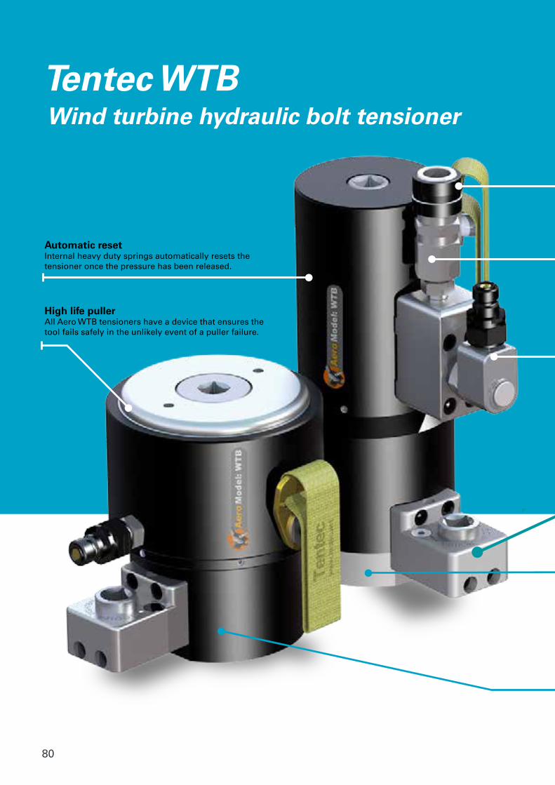
80
Tentec WTB Wind turbine hydraulic bolt tensioner
High life pullerAll Aero WTB tensioners have a device that ensures the tool fails safely in the unlikely event of a puller failure.
Automatic resetInternal heavy duty springs automatically resets the tensioner once the pressure has been released.
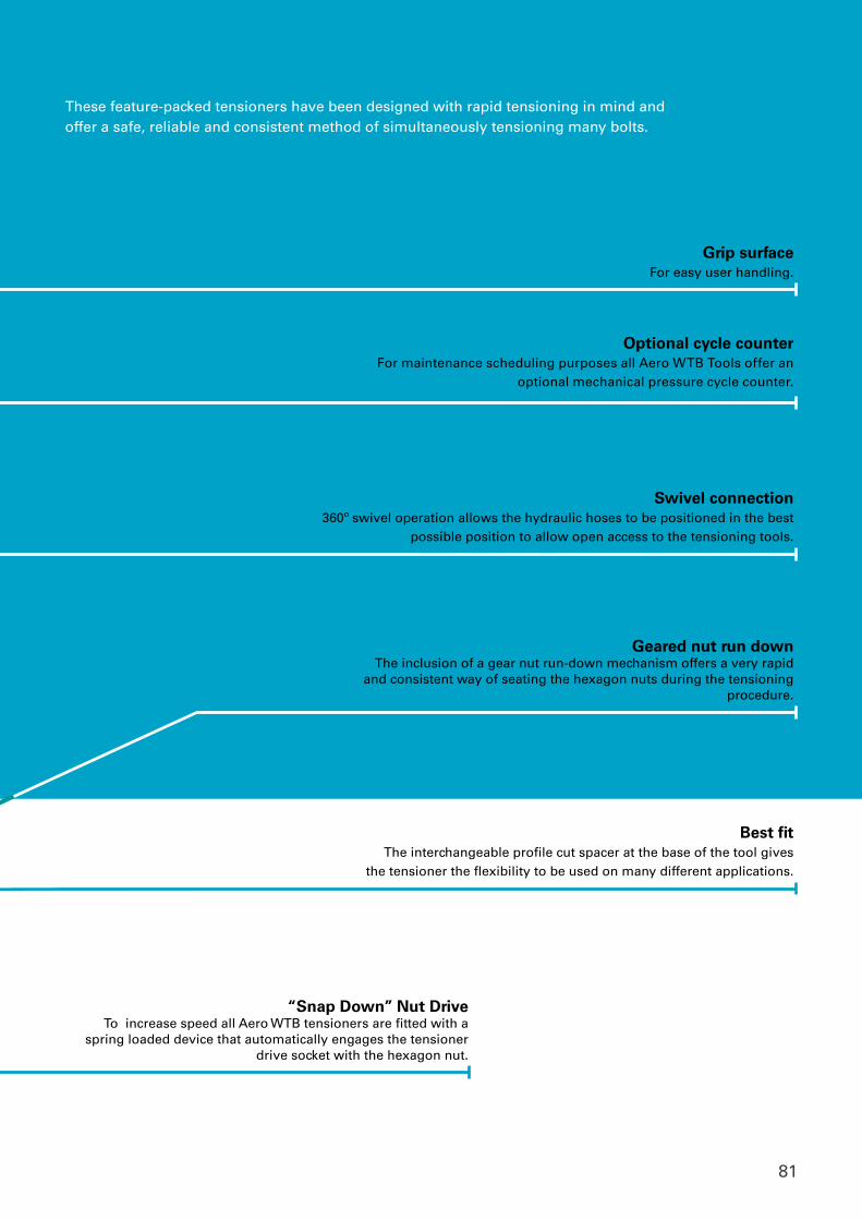
81
Grip surfaceFor easy user handling.
Swivel connection360º swivel operation allows the hydraulic hoses to be positioned in the best
possible position to allow open access to the tensioning tools.
Optional cycle counterFor maintenance scheduling purposes all Aero WTB Tools offer an
optional mechanical pressure cycle counter.
Geared nut run downThe inclusion of a gear nut run-down mechanism offers a very rapid
and consistent way of seating the hexagon nuts during the tensioning procedure.
Best fitThe interchangeable profile cut spacer at the base of the tool gives
the tensioner the flexibility to be used on many different applications.
“Snap Down” Nut DriveTo increase speed all Aero WTB tensioners are fitted with a
spring loaded device that automatically engages the tensioner drive socket with the hexagon nut.
These feature-packed tensioners have been designed with rapid tensioning in mind and offer a safe, reliable and consistent method of simultaneously tensioning many bolts.
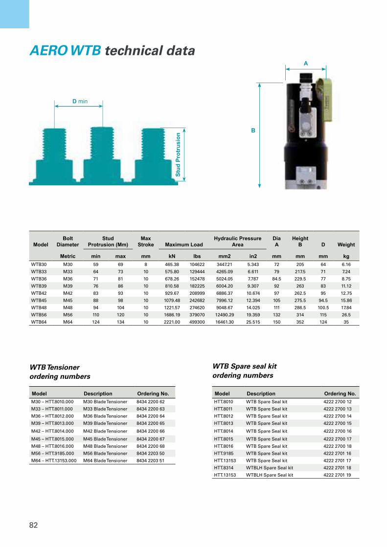
82
D min
Stud
Pro
trus
ion
A
B
ModelBolt
DiameterStud
Protrusion (Mm)Max
Stroke Maximum LoadHydraulic Pressure
AreaDia A
Height B D Weight
Metric min max mm kN lbs mm2 in2 mm mm mm kgWTB30 M30 59 69 8 465.38 104622 3447.21 5.343 72 205 64 6.16
WTB33 M33 64 73 10 575.80 129444 4265.09 6.611 79 217.5 71 7.24
WTB36 M36 71 81 10 678.26 152478 5024.05 7.787 84.5 229.5 77 8.75
WTB39 M39 76 86 10 810.58 182225 6004.20 9.307 92 263 83 11.12
WTB42 M42 83 93 10 929.67 208999 6886.37 10.674 97 262.5 95 12.75
WTB45 M45 88 98 10 1079.48 242682 7996.12 12.394 105 275.5 94.5 15.86
WTB48 M48 94 104 10 1221.57 274620 9048.67 14.025 111 286.5 100.5 17.84
WTB56 M56 110 120 10 1686.19 379070 12490.29 19.359 132 314 115 26.5
WTB64 M64 124 134 10 2221.00 499300 16461.30 25.515 150 352 124 35
AERO WTB technical data
WTB Spare seal kit ordering numbers
Model Description Ordering No.HTT.8010 WTB Spare Seal kit 4222 2700 12
HTT.8011 WTB Spare Seal kit 4222 2700 13
HTT.8012 WTB Spare Seal kit 4222 2700 14
HTT.8013 WTB Spare Seal kit 4222 2700 15
HTT.8014 WTB Spare Seal kit 4222 2700 16
HTT.8015 WTB Spare Seal kit 4222 2700 17
HTT.8016 WTB Spare Seal kit 4222 2700 18
HTT.9185 WTB Spare Seal kit 4222 2701 16
HTT.13153 WTB Spare Seal kit 4222 2701 17
HTT.8314 WTBLH Spare Seal kit 4222 2701 18
HTT.13153 WTBLH Spare Seal kit 4222 2701 19
WTB Tensionerordering numbers
Model Description Ordering No.M30 – HTT.8010.000 M30 Blade Tensioner 8434 2200 62
M33 – HTT.8011.000 M33 Blade Tensioner 8434 2200 63
M36 – HTT.8012.000 M36 Blade Tensioner 8434 2200 64
M39 – HTT.8013.000 M39 Blade Tensioner 8434 2200 65
M42 – HTT.8014.000 M42 Blade Tensioner 8434 2200 66
M45 – HTT.8015.000 M45 Blade Tensioner 8434 2200 67
M48 – HTT.8016.000 M48 Blade Tensioner 8434 2200 68
M56 – HTT.9185.000 M56 Blade Tensioner 8434 2203 50
M64 – HTT.13153.000 M64 Blade Tensioner 8434 2203 51
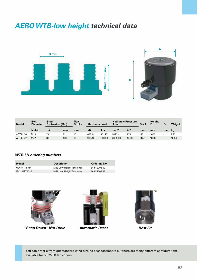
83
A
B
D min
Stud
Pro
trus
ion
Best FitAutomatic Reset“Snap Down” Nut Drive
ModelBolt Diameter
Stud Protrusion (Mm)
Max Stroke Maximum Load
Hydraulic Pressure Area Dia A
Height B D Weight
Metric min max mm kN lbs mm2 in2 mm mm mm kgWTBLH36 M36 71 91 10 678.14 152452 5023.4 7.79 123 167.5 - 9.97
WTBLH42 M42 83 103 10 930.15 209106 6889.96 10.68 142.5 181.3 - 13.94
AERO WTB-low height technical data
WTB-LH ordering numbers
Model Description Ordering No.M36-HTT.8314 M36 Low Height Tensioner 8434 2203 52
M42- HTT.8315 M42 Low Height Tensioner 8434 2203 53
You can order a from our standard wind turbine base tensioners but there are many different configurationsavailable for our WTB tensioners.

84
Tentec WTFWind turbine foundation hydraulic bolt tensioner
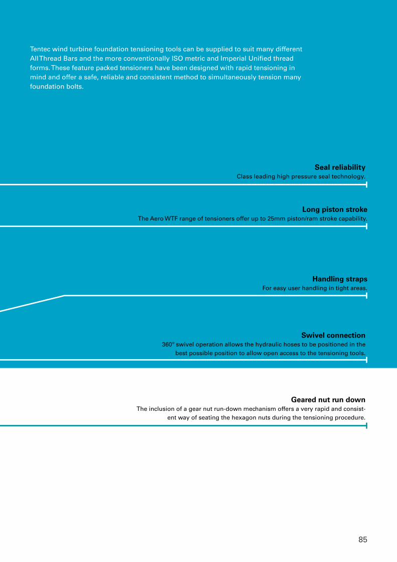
85
Handling strapsFor easy user handling in tight areas.
Long piston strokeThe Aero WTF range of tensioners offer up to 25mm piston/ram stroke capability.
Swivel connection360º swivel operation allows the hydraulic hoses to be positioned in the
best possible position to allow open access to the tensioning tools.
Geared nut run downThe inclusion of a gear nut run-down mechanism offers a very rapid and consist-
ent way of seating the hexagon nuts during the tensioning procedure.
Tentec wind turbine foundation tensioning tools can be supplied to suit many different All Thread Bars and the more conventionally ISO metric and Imperial Unified thread forms. These feature packed tensioners have been designed with rapid tensioning in mind and offer a safe, reliable and consistent method to simultaneously tension many foundation bolts.
Seal reliabilityClass leading high pressure seal technology.
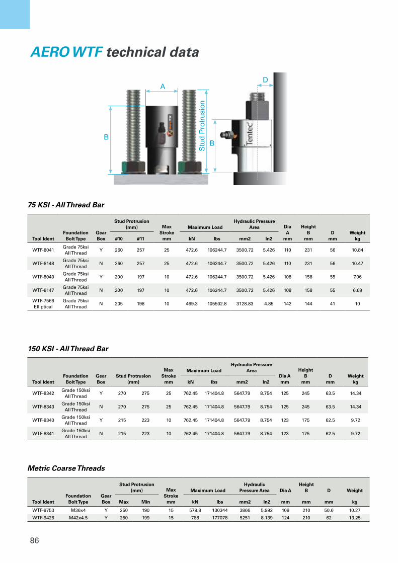
86
D
BB
Stu
d P
rotru
sion
A
AeroWTF
AERO WTF technical data
Tool IdentFoundation
Bolt Type Gear Box
Stud Protrusion (mm) Max
Strokemm
Maximum LoadHydraulic Pressure
Area Dia A
mm
Height B
mmD
mmWeight
kg#10 #11 kN lbs mm2 In2
WTF-8041Grade 75ksi All Thread
Y 260 257 25 472.6 106244.7 3500.72 5.426 110 231 56 10.84
WTF-8148Grade 75ksi All Thread
N 260 257 25 472.6 106244.7 3500.72 5.426 110 231 56 10.47
WTF-8040Grade 75ksi All Thread
Y 200 197 10 472.6 106244.7 3500.72 5.426 108 158 55 7.06
WTF-8147Grade 75ksi All Thread
N 200 197 10 472.6 106244.7 3500.72 5.426 108 158 55 6.69
WTF-7566 Elliptical
Grade 75ksi All Thread
N 205 198 10 469.3 105502.8 3128.83 4.85 142 144 41 10
Tool IdentFoundation
Bolt Type Gear Box
Stud Protrusion (mm)
Max Stroke
mm
Maximum LoadHydraulic Pressure
AreaDia Amm
Height B
mmD
mmWeight
kgkN lbs mm2 In2
WTF-8342Grade 150ksi
All ThreadY 270 275 25 762.45 171404.8 5647.79 8.754 125 245 63.5 14.34
WTF-8343Grade 150ksi
All ThreadN 270 275 25 762.45 171404.8 5647.79 8.754 125 245 63.5 14.34
WTF-8340Grade 150ksi
All ThreadY 215 223 10 762.45 171404.8 5647.79 8.754 123 175 62.5 9.72
WTF-8341Grade 150ksi
All ThreadN 215 223 10 762.45 171404.8 5647.79 8.754 123 175 62.5 9.72
Tool IdentFoundation
Bolt Type Gear Box
Stud Protrusion (mm) Max
Strokemm
Maximum LoadHydraulic
Pressure Area Dia AHeight
B D Weight
Max Min kN lbs mm2 In2 mm mm mm kg
WTF-9753 M36x4 Y 250 190 15 579.8 130344 3866 5.992 108 210 50.6 10.27
WTF-9426 M42x4.5 Y 250 199 15 788 177078 5251 8.139 124 210 62 13.25
75 KSI - All Thread Bar
150 KSI - All Thread Bar
Metric Coarse Threads
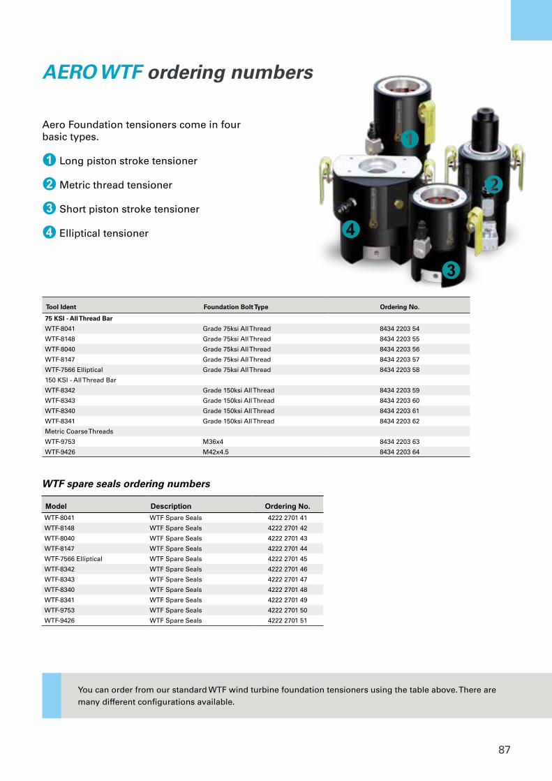
87
AERO WTF ordering numbers
Tool Ident Foundation Bolt Type Ordering No.
75 KSI - All Thread Bar
WTF-8041 Grade 75ksi All Thread 8434 2203 54
WTF-8148 Grade 75ksi All Thread 8434 2203 55
WTF-8040 Grade 75ksi All Thread 8434 2203 56
WTF-8147 Grade 75ksi All Thread 8434 2203 57
WTF-7566 Elliptical Grade 75ksi All Thread 8434 2203 58
150 KSI - All Thread Bar
WTF-8342 Grade 150ksi All Thread 8434 2203 59
WTF-8343 Grade 150ksi All Thread 8434 2203 60
WTF-8340 Grade 150ksi All Thread 8434 2203 61
WTF-8341 Grade 150ksi All Thread 8434 2203 62
Metric Coarse Threads
WTF-9753 M36x4 8434 2203 63
WTF-9426 M42x4.5 8434 2203 64
WTF spare seals ordering numbers
Model Description Ordering No.WTF-8041 WTF Spare Seals 4222 2701 41
WTF-8148 WTF Spare Seals 4222 2701 42
WTF-8040 WTF Spare Seals 4222 2701 43
WTF-8147 WTF Spare Seals 4222 2701 44
WTF-7566 Elliptical WTF Spare Seals 4222 2701 45
WTF-8342 WTF Spare Seals 4222 2701 46
WTF-8343 WTF Spare Seals 4222 2701 47
WTF-8340 WTF Spare Seals 4222 2701 48
WTF-8341 WTF Spare Seals 4222 2701 49
WTF-9753 WTF Spare Seals 4222 2701 50
WTF-9426 WTF Spare Seals 4222 2701 51
Aero Foundation tensioners come in four basic types.
1 Long piston stroke tensioner
2 Metric thread tensioner
3 Short piston stroke tensioner
4 Elliptical tensioner 4
3
1
2
You can order from our standard WTF wind turbine foundation tensioners using the table above. There are many different configurations available.
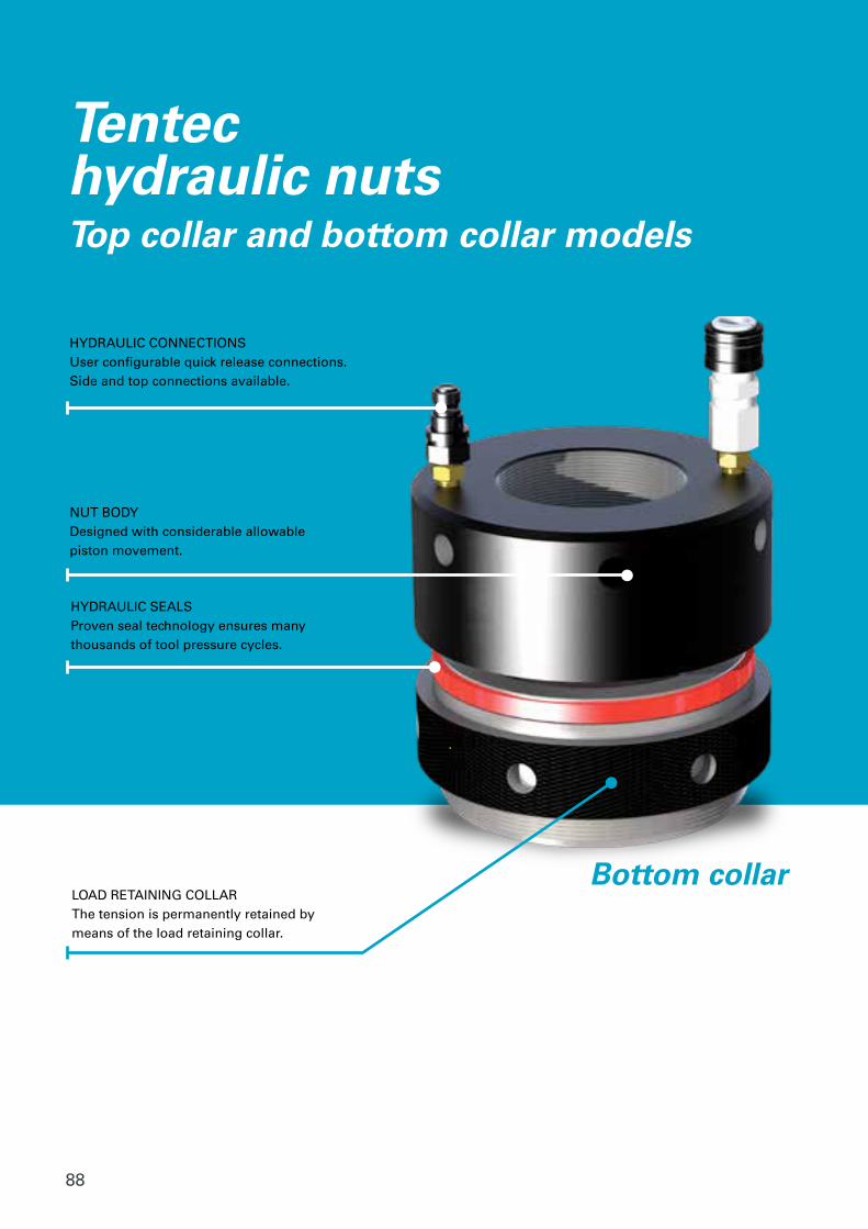
88
Tentechydraulic nutsTop collar and bottom collar models
HYDRAULIC CONNECTIONSUser configurable quick release connections.Side and top connections available.
NUT BODYDesigned with considerable allowable piston movement.
HYDRAULIC SEALSProven seal technology ensures many thousands of tool pressure cycles.
LOAD RETAINING COLLARThe tension is permanently retained by means of the load retaining collar.
Bottom collar
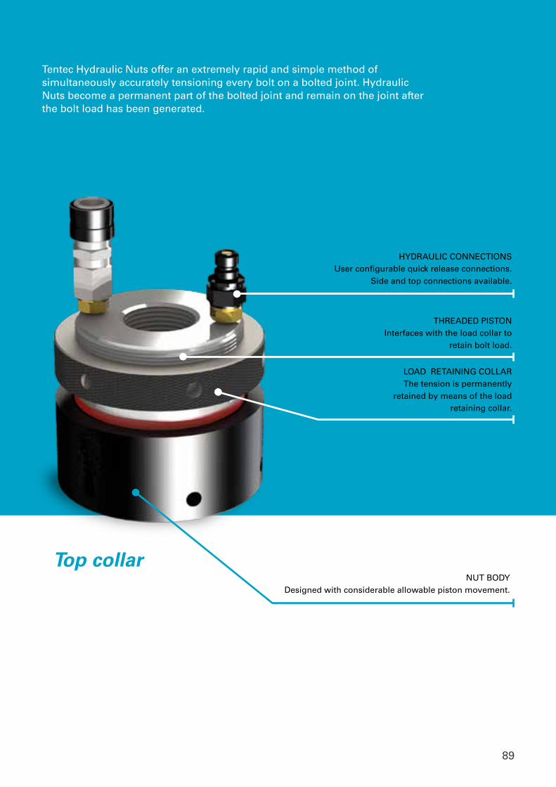
89
HYDRAULIC CONNECTIONSUser configurable quick release connections.
Side and top connections available.
LOAD RETAINING COLLARThe tension is permanently
retained by means of the load retaining collar.
THREADED PISTONInterfaces with the load collar to
retain bolt load.
Top collar NUT BODY
Designed with considerable allowable piston movement.
Tentec Hydraulic Nuts offer an extremely rapid and simple method of simultaneously accurately tensioning every bolt on a bolted joint. Hydraulic Nuts become a permanent part of the bolted joint and remain on the joint after the bolt load has been generated.
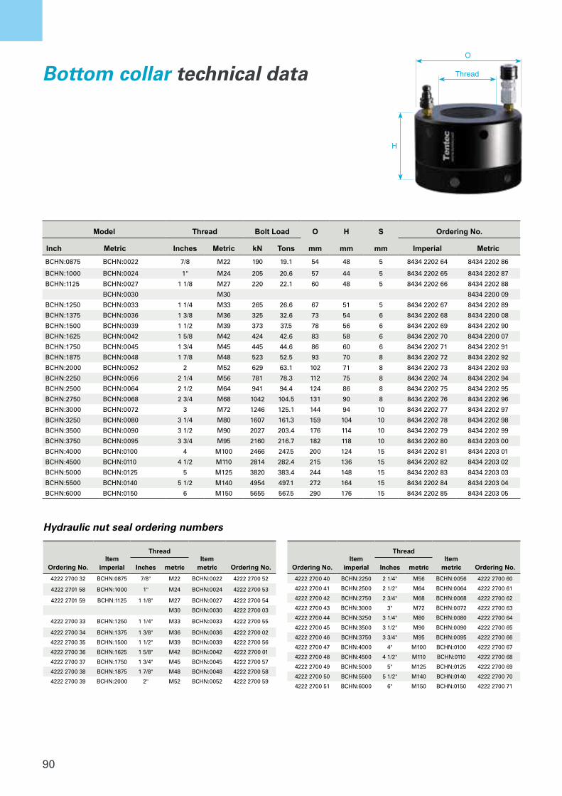
90
Hydraulic pressure is applied simultaneously to each Tentec Nut. All frictional factors connected with conventional bolt tightening methods are alleviated since Tentec Nuts apply a direct axial force to the bolt which generates a bolt elongation. This elongation/tension is perma-nently retained by means of the load retaining collar. Tentec Nuts have been designed to be as compact as possible, in order to allow adjacent fitment on as many applications as possible. In most cases they are designed to produce a residual bolt stress of 45000 lbs/In2 (310N/mm2) which is more than adequate for most bolted joint applications. As pressure is applied to the Tentec Nuts not only does the bolt elon-gate but also joint compression occurs. Since many applications incor-
BOLT TIGHTENING SOLUTIONSWe have many years experience of designing bespoke bolt tensioning tools for instances where standard hydraulic nuts are not suitable. Contact us for more information
TENTEC HYDRAULIC NUTSTYPE - BOTTOM COLLAR
TECHNICAL SPECIFICATIONS Maximum Working Pressure = 2275bar
Nut BodyDesigned with considerable allowable ram movement. Refer to column S below
Hydraulic ConnectionsUser configurable quick release connections.Side and top connections available
Hydraulic SealsProven seal technology ensures many 1000’s of tool pressure cycles
Load Collar
Threaded RamInterfaces with the load collar to
retain bolt load
porate some form of gasket, this joint compression can be substantial, in order to withstand this joint compression all Tentec Nuts are capable of considerable piston movement. This allows the Tentec Nuts, in most cases, the ability to tension a complete joint in only one pressurisation sequence, which can result in extremely high time savings.
O
Thread
H
Part No Thread Thread Part No Bolt Load O H S
Inch Inches Metric Metric kn Tons mm mm mm
BCHN:0875 7/8 M22 BCHN:0022 190 19.1 54 48 5
BCHN:1000 1" M24 BCHN:0024 205 20.6 57 44 5
BCHN:1125 1 1/8 M27 BCHN:0027 220 22.1 60 48 5
BCHN:1250 1 1/4 M33 BCHN:0033 265 26.6 67 51 5
BCHN:1375 1 3/8 M36 BCHN:0036 325 32.6 73 54 6
BCHN:1500 1 1/2 M39 BCHN:0039 373 37.5 78 56 6
BCHN:1625 1 5/8 M42 BCHN:0042 424 42.6 83 58 6
BCHN:1750 1 3/4 M45 BCHN:0045 445 44.6 86 60 6
BCHN:1875 1 7/8 M48 BCHN:0048 523 52.5 93 70 8
BCHN:2000 2 M52 BCHN:0052 629 63.1 102 71 8
BCHN:2250 2 1/4 M56 BCHN:0056 781 78.3 112 75 8
BCHN:2500 2 1/2 M64 BCHN:0064 941 94.4 124 86 8
BCHN:2750 2 3/4 M68 BCHN:0068 1042 104.5 131 90 8
BCHN:3000 3 M72 BCHN:0072 1246 125.1 144 94 10
BCHN:3250 3 1/4 M80 BCHN:0080 1607 161.3 159 104 10
BCHN:3500 3 1/2 M90 BCHN:0090 2027 203.4 176 114 10
BCHN:3750 3 3/4 M95 BCHN:0095 2160 216.7 182 118 10
BCHN:4000 4 M100 BCHN:0100 2466 247.5 200 124 15
BCHN:4500 4 1/2 M110 BCHN:0110 2814 282.4 215 136 15
BCHN:5000 5 M125 BCHN:0125 3820 383.4 244 148 15
BCHN:5500 5 1/2 M140 BCHN:0140 4954 497.1 272 164 15
BCHN:6000 6 M150 BCHN:0150 5655 567.5 290 176 15Model Thread Bolt Load O H S Ordering No.
Inch Metric Inches Metric kN Tons mm mm mm Imperial MetricBCHN:0875 BCHN:0022 7/8 M22 190 19.1 54 48 5 8434 2202 64 8434 2202 86
BCHN:1000 BCHN:0024 1" M24 205 20.6 57 44 5 8434 2202 65 8434 2202 87
BCHN:1125 BCHN:0027 1 1/8 M27 220 22.1 60 48 5 8434 2202 66 8434 2202 88
BCHN:0030 M30 8434 2200 09
BCHN:1250 BCHN:0033 1 1/4 M33 265 26.6 67 51 5 8434 2202 67 8434 2202 89
BCHN:1375 BCHN:0036 1 3/8 M36 325 32.6 73 54 6 8434 2202 68 8434 2200 08
BCHN:1500 BCHN:0039 1 1/2 M39 373 37.5 78 56 6 8434 2202 69 8434 2202 90
BCHN:1625 BCHN:0042 1 5/8 M42 424 42.6 83 58 6 8434 2202 70 8434 2200 07
BCHN:1750 BCHN:0045 1 3/4 M45 445 44.6 86 60 6 8434 2202 71 8434 2202 91
BCHN:1875 BCHN:0048 1 7/8 M48 523 52.5 93 70 8 8434 2202 72 8434 2202 92
BCHN:2000 BCHN:0052 2 M52 629 63.1 102 71 8 8434 2202 73 8434 2202 93
BCHN:2250 BCHN:0056 2 1/4 M56 781 78.3 112 75 8 8434 2202 74 8434 2202 94
BCHN:2500 BCHN:0064 2 1/2 M64 941 94.4 124 86 8 8434 2202 75 8434 2202 95
BCHN:2750 BCHN:0068 2 3/4 M68 1042 104.5 131 90 8 8434 2202 76 8434 2202 96
BCHN:3000 BCHN:0072 3 M72 1246 125.1 144 94 10 8434 2202 77 8434 2202 97
BCHN:3250 BCHN:0080 3 1/4 M80 1607 161.3 159 104 10 8434 2202 78 8434 2202 98
BCHN:3500 BCHN:0090 3 1/2 M90 2027 203.4 176 114 10 8434 2202 79 8434 2202 99
BCHN:3750 BCHN:0095 3 3/4 M95 2160 216.7 182 118 10 8434 2202 80 8434 2203 00
BCHN:4000 BCHN:0100 4 M100 2466 247.5 200 124 15 8434 2202 81 8434 2203 01
BCHN:4500 BCHN:0110 4 1/2 M110 2814 282.4 215 136 15 8434 2202 82 8434 2203 02
BCHN:5000 BCHN:0125 5 M125 3820 383.4 244 148 15 8434 2202 83 8434 2203 03
BCHN:5500 BCHN:0140 5 1/2 M140 4954 497.1 272 164 15 8434 2202 84 8434 2203 04
BCHN:6000 BCHN:0150 6 M150 5655 567.5 290 176 15 8434 2202 85 8434 2203 05
Bottom collar technical data
Hydraulic nut seal ordering numbers
Ordering No.Item
imperial
ThreadItem
metric Ordering No.Inches metric
4222 2700 32 BCHN:0875 7/8" M22 BCHN:0022 4222 2700 52
4222 2701 58 BCHN:1000 1" M24 BCHN:0024 4222 2700 53
4222 2701 59 BCHN:1125 1 1/8" M27 BCHN:0027 4222 2700 54
M30 BCHN:0030 4222 2700 03
4222 2700 33 BCHN:1250 1 1/4" M33 BCHN:0033 4222 2700 55
4222 2700 34 BCHN:1375 1 3/8" M36 BCHN:0036 4222 2700 02
4222 2700 35 BCHN:1500 1 1/2" M39 BCHN:0039 4222 2700 56
4222 2700 36 BCHN:1625 1 5/8" M42 BCHN:0042 4222 2700 01
4222 2700 37 BCHN:1750 1 3/4" M45 BCHN:0045 4222 2700 57
4222 2700 38 BCHN:1875 1 7/8" M48 BCHN:0048 4222 2700 58
4222 2700 39 BCHN:2000 2" M52 BCHN:0052 4222 2700 59
Ordering No.Item
imperial
ThreadItem
metric Ordering No.Inches metric
4222 2700 40 BCHN:2250 2 1/4" M56 BCHN:0056 4222 2700 60
4222 2700 41 BCHN:2500 2 1/2" M64 BCHN:0064 4222 2700 61
4222 2700 42 BCHN:2750 2 3/4" M68 BCHN:0068 4222 2700 62
4222 2700 43 BCHN:3000 3" M72 BCHN:0072 4222 2700 63
4222 2700 44 BCHN:3250 3 1/4" M80 BCHN:0080 4222 2700 64
4222 2700 45 BCHN:3500 3 1/2" M90 BCHN:0090 4222 2700 65
4222 2700 46 BCHN:3750 3 3/4" M95 BCHN:0095 4222 2700 66
4222 2700 47 BCHN:4000 4" M100 BCHN:0100 4222 2700 67
4222 2700 48 BCHN:4500 4 1/2" M110 BCHN:0110 4222 2700 68
4222 2700 49 BCHN:5000 5" M125 BCHN:0125 4222 2700 69
4222 2700 50 BCHN:5500 5 1/2" M140 BCHN:0140 4222 2700 70
4222 2700 51 BCHN:6000 6" M150 BCHN:0150 4222 2700 71
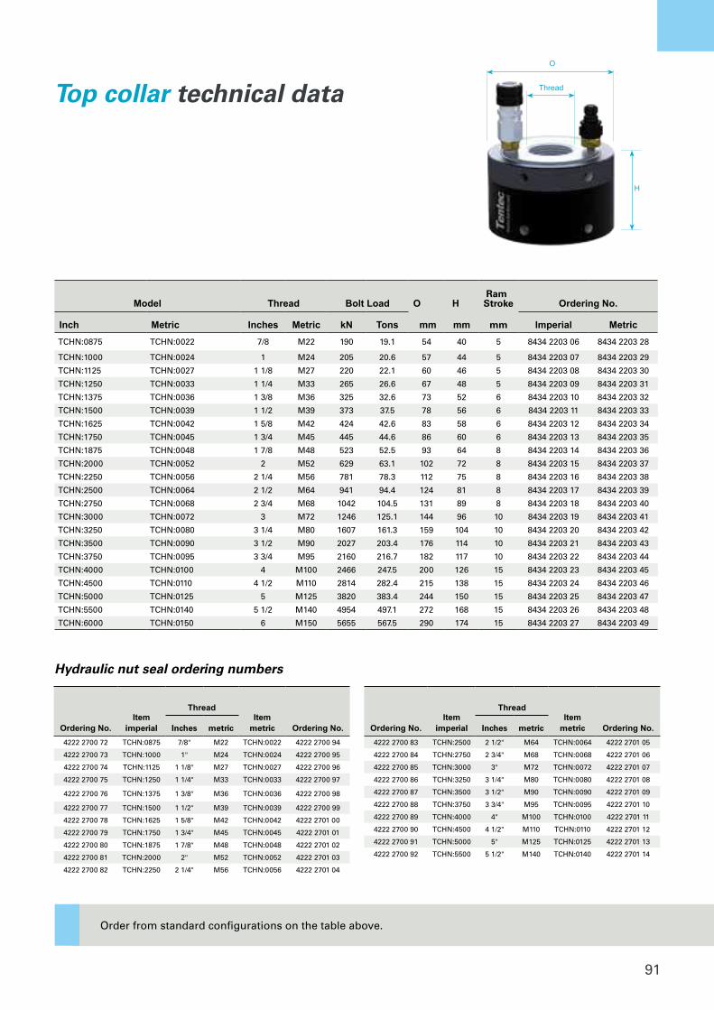
91
TENTEC HYDRAULIC NUTSTYPE - TOP COLLAR
Maximum Working Pressure = 2275bar
Safety & ReliabilityIntegrated into the design of each hydraulic nut are enhanced safety
features including mechanisms to remove the hazard of over-stroking
the hydraulic rams All Tentec hydraulic nuts feature a mechanism
which directs oil flow away from the operator in the instance the ram
is over-stroked and exhausts oil harmlessly into the internal section
of the nut
Seal TechnologyOver the years Tentec has developed a class leading high pressure
seal technology. This innovative seal technology is industry proven
and offers many 1000’s of reliable and safe pressure cycles.
TECHNICAL SPECIFICATIONS
Designs and specifications are subject to change without notice or obligation. Read all safety instructions in the manual before usage.
Top Collar Hydraulic Nuts feature the same benefits as the Bottom Collar type Hydraulic Nuts. The Top Collar derivative is ideally used where the nut is sunk into a pocket or spot face. The load retaining collar is situated at the top of the hydraulic nut allowing for easy access by the user.
Nut BodyDesigned with considerable allowable ram movement.
Hydraulic ConnectionsUser configurable quick release connections.Side and top connections available
Hydraulic SealsProven seal technology ensures many 1000’s of tool pressure cycles
Load Collar Threaded Ram
Interfaces with the load collar to retain bolt load
Part No Thread Thread Part No O H Ram Stroke
Inch Inches Metric Metric kN Tons mm mm mm
TCHN:0875 7/8 M22 TCHN:0022 190 19.1 54 40 5
TCHN:1000 1 M24 TCHN:0024 205 20.6 57 44 5
TCHN:1125 1 1/8 M27 TCHN:0027 220 22.1 60 46 5
TCHN:1250 1 1/4 M33 TCHN:0033 265 26.6 67 48 5
TCHN:1375 1 3/8 M36 TCHN:0036 325 32.6 73 52 6
TCHN:1500 1 1/2 M39 TCHN:0039 373 37.5 78 56 6
TCHN:1625 1 5/8 M42 TCHN:0042 424 42.6 83 58 6
TCHN:1750 1 3/4 M45 TCHN:0045 445 44.6 86 60 6
TCHN:1875 1 7/8 M48 TCHN:0048 523 52.5 93 64 8
TCHN:2000 2 M52 TCHN:0052 629 63.1 102 72 8
TCHN:2250 2 1/4 M56 TCHN:0056 781 78.3 112 75 8
TCHN:2500 2 1/2 M64 TCHN:0064 941 94.4 124 81 8
TCHN:2750 2 3/4 M68 TCHN:0068 1042 104.5 131 89 8
TCHN:3000 3 M72 TCHN:0072 1246 125.1 144 96 10
TCHN:3250 3 1/4 M80 TCHN:0080 1607 161.3 159 104 10
TCHN:3500 3 1/2 M90 TCHN:0090 2027 203.4 176 114 10
TCHN:3750 3 3/4 M95 TCHN:0095 2160 216.7 182 117 10
TCHN:4000 4 M100 TCHN:0100 2466 247.5 200 126 15
TCHN:4500 4 1/2 M110 TCHN:0110 2814 282.4 215 138 15
TCHN:5000 5 M125 TCHN:0125 3820 383.4 244 150 15
TCHN:5500 5 1/2 M140 TCHN:0140 4954 497.1 272 168 15
TCHN:6000 6 M150 TCHN:0150 5655 567.5 290 174 15
Bolt Load
O
Thread
H
Model Thread Bolt Load O H Ram Stroke Ordering No.
Inch Metric Inches Metric kN Tons mm mm mm Imperial MetricTCHN:0875 TCHN:0022 7/8 M22 190 19.1 54 40 5 8434 2203 06 8434 2203 28
TCHN:1000 TCHN:0024 1 M24 205 20.6 57 44 5 8434 2203 07 8434 2203 29
TCHN:1125 TCHN:0027 1 1/8 M27 220 22.1 60 46 5 8434 2203 08 8434 2203 30
TCHN:1250 TCHN:0033 1 1/4 M33 265 26.6 67 48 5 8434 2203 09 8434 2203 31
TCHN:1375 TCHN:0036 1 3/8 M36 325 32.6 73 52 6 8434 2203 10 8434 2203 32
TCHN:1500 TCHN:0039 1 1/2 M39 373 37.5 78 56 6 8434 2203 11 8434 2203 33
TCHN:1625 TCHN:0042 1 5/8 M42 424 42.6 83 58 6 8434 2203 12 8434 2203 34
TCHN:1750 TCHN:0045 1 3/4 M45 445 44.6 86 60 6 8434 2203 13 8434 2203 35
TCHN:1875 TCHN:0048 1 7/8 M48 523 52.5 93 64 8 8434 2203 14 8434 2203 36
TCHN:2000 TCHN:0052 2 M52 629 63.1 102 72 8 8434 2203 15 8434 2203 37
TCHN:2250 TCHN:0056 2 1/4 M56 781 78.3 112 75 8 8434 2203 16 8434 2203 38
TCHN:2500 TCHN:0064 2 1/2 M64 941 94.4 124 81 8 8434 2203 17 8434 2203 39
TCHN:2750 TCHN:0068 2 3/4 M68 1042 104.5 131 89 8 8434 2203 18 8434 2203 40
TCHN:3000 TCHN:0072 3 M72 1246 125.1 144 96 10 8434 2203 19 8434 2203 41
TCHN:3250 TCHN:0080 3 1/4 M80 1607 161.3 159 104 10 8434 2203 20 8434 2203 42
TCHN:3500 TCHN:0090 3 1/2 M90 2027 203.4 176 114 10 8434 2203 21 8434 2203 43
TCHN:3750 TCHN:0095 3 3/4 M95 2160 216.7 182 117 10 8434 2203 22 8434 2203 44
TCHN:4000 TCHN:0100 4 M100 2466 247.5 200 126 15 8434 2203 23 8434 2203 45
TCHN:4500 TCHN:0110 4 1/2 M110 2814 282.4 215 138 15 8434 2203 24 8434 2203 46
TCHN:5000 TCHN:0125 5 M125 3820 383.4 244 150 15 8434 2203 25 8434 2203 47
TCHN:5500 TCHN:0140 5 1/2 M140 4954 497.1 272 168 15 8434 2203 26 8434 2203 48
TCHN:6000 TCHN:0150 6 M150 5655 567.5 290 174 15 8434 2203 27 8434 2203 49
Top collar technical data
Hydraulic nut seal ordering numbers
Ordering No.Item
imperial
ThreadItem
metric Ordering No.Inches metric
4222 2700 72 TCHN:0875 7/8" M22 TCHN:0022 4222 2700 94
4222 2700 73 TCHN:1000 1" M24 TCHN:0024 4222 2700 95
4222 2700 74 TCHN:1125 1 1/8" M27 TCHN:0027 4222 2700 96
4222 2700 75 TCHN:1250 1 1/4" M33 TCHN:0033 4222 2700 97
4222 2700 76 TCHN:1375 1 3/8" M36 TCHN:0036 4222 2700 98
4222 2700 77 TCHN:1500 1 1/2" M39 TCHN:0039 4222 2700 99
4222 2700 78 TCHN:1625 1 5/8" M42 TCHN:0042 4222 2701 00
4222 2700 79 TCHN:1750 1 3/4" M45 TCHN:0045 4222 2701 01
4222 2700 80 TCHN:1875 1 7/8" M48 TCHN:0048 4222 2701 02
4222 2700 81 TCHN:2000 2" M52 TCHN:0052 4222 2701 03
4222 2700 82 TCHN:2250 2 1/4" M56 TCHN:0056 4222 2701 04
Ordering No.Item
imperial
ThreadItem
metric Ordering No.Inches metric
4222 2700 83 TCHN:2500 2 1/2" M64 TCHN:0064 4222 2701 05
4222 2700 84 TCHN:2750 2 3/4" M68 TCHN:0068 4222 2701 06
4222 2700 85 TCHN:3000 3" M72 TCHN:0072 4222 2701 07
4222 2700 86 TCHN:3250 3 1/4" M80 TCHN:0080 4222 2701 08
4222 2700 87 TCHN:3500 3 1/2" M90 TCHN:0090 4222 2701 09
4222 2700 88 TCHN:3750 3 3/4" M95 TCHN:0095 4222 2701 10
4222 2700 89 TCHN:4000 4" M100 TCHN:0100 4222 2701 11
4222 2700 90 TCHN:4500 4 1/2" M110 TCHN:0110 4222 2701 12
4222 2700 91 TCHN:5000 5" M125 TCHN:0125 4222 2701 13
4222 2700 92 TCHN:5500 5 1/2" M140 TCHN:0140 4222 2701 14
Order from standard configurations on the table above.
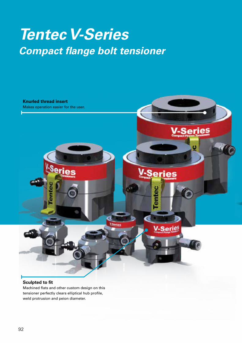
92
Tentec V-SeriesCompact flange bolt tensioner
Knurled thread insertMakes operation easier for the user.
Sculpted to fitMachined flats and other custom design on this tensioner perfectly clears elliptical hub profile, weld protrusion and peion diameter.
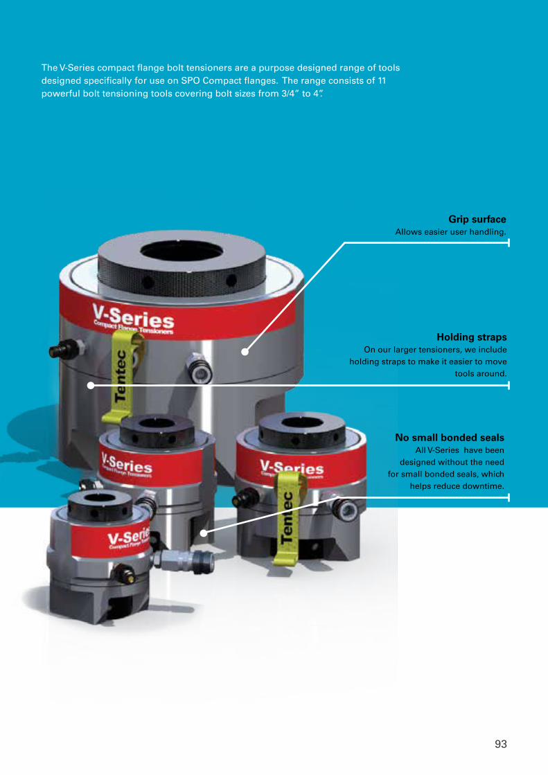
93
The V-Series compact flange bolt tensioners are a purpose designed range of tools designed specifically for use on SPO Compact flanges. The range consists of 11 powerful bolt tensioning tools covering bolt sizes from 3/4” to 4”.
Grip surfaceAllows easier user handling.
Holding strapsOn our larger tensioners, we include
holding straps to make it easier to move tools around.
No small bonded sealsAll V-Series have been
designed without the need for small bonded seals, which
helps reduce downtime.
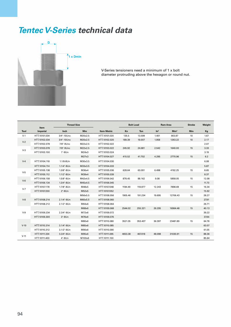
94
D
1 x Dmin
Tool
Item
Imperial
Thread Size
Item Metric
Bolt Load Ram Area Stroke Weight
Inch Mm Kn Ton In² Mm² Mm Kg
V-1 HTT.10101.034 3/4"-10Unc M20x2.5 HTT.10101.020 135.5 13.599 1.401 903.87 10 1.67
V-2HTT.10102.034 3/4"-10Unc M20x2.5 HTT.10102.020 189.39 19.007 1.958 1263.22 10 2.17
HTT.10102.078 7/8"-9Unc M22x2.5 HTT.10102.022 2.07
V-3HTT.10103.078 7/8"-9Unc M22x2.5 HTT.10103.022 245.92 24.681 2.542 1640.00 15 3.33
HTT.10103.100 1"-8Un M24x3 HTT.10103.024 3.19
V-4
M27x3 HTT.10104.027 415.52 41.702 4.295 2770.96 15 6.2
HTT.10104.118 1.1/8-8Un M30x3.5 HTT.10104.030 6.08
HTT.10104.114 1.1/4"-8Un M33x3.5 HTT.10104.033 5.87
V-5HTT.10105.138 1.3/8"-8Un M36x4 HTT.10105.036 628.64 63.091 6.498 4192.25 15 8.65
HTT.10105.112 1.1/2"-8Un M39x4 HTT.10105.039 8.37
V-6HTT.10106.158 1.5/8"-8Un M42x4.5 HTT.10106.042 878.45 88.162 9.08 5858.05 15 12.08
HTT.10106.134 1.3/4"-8Un M45x4.5 HTT.10106.045 11.73
V-7HTT.10107.178 1.7/8"-8Un M48x5 HTT.10107.048 1184.49 118.877 12.243 7898.69 15 16.34
HTT.10107.200 2"-8Un M52x5 HTT.10107.052 15.92
V-8
M56x5.5 HTT.10108.056 1905.46 191.234 19.695 12706.43 15 28.27
HTT.10108.214 2.1/4"-8Un M60x5.5 HTT.10108.060 27.91
HTT.10108.212 2.1/2"-8Un M64x6 HTT.10108.064 26.71
V-9
M68x6 HTT.10109.068 2544.02 255.321 26.295 16964.48 15 40.13
HTT.10109.234 2.3/4"-8Un M72x6 HTT.10109.072 39.22
HTT.10109.300 3"-8Un M76x6 HTT.10109.076 37.64
V-10
M80x6 HTT.10110.080 3521.35 353.407 36.397 23481.89 15 64.76
HTT.10110.314 3.1/4"-8Un M85x6 HTT.10110.085 63.07
HTT.10110.312 3.1/2"-8Un M90x6 HTT.10110.090 61.05
V-11HTT.10111.334 3.3/4"-8Un M95x6 HTT.10111.095 4653.38 467.018 48.098 31030.91 15 88.36
HTT.10111.400 4"-8Un M100x6 HTT.10111.100 85.64
Tentec V-Series technical data
V-Series tensioners need a minimum of 1 x bolt diameter protruding above the hexagon or round nut.
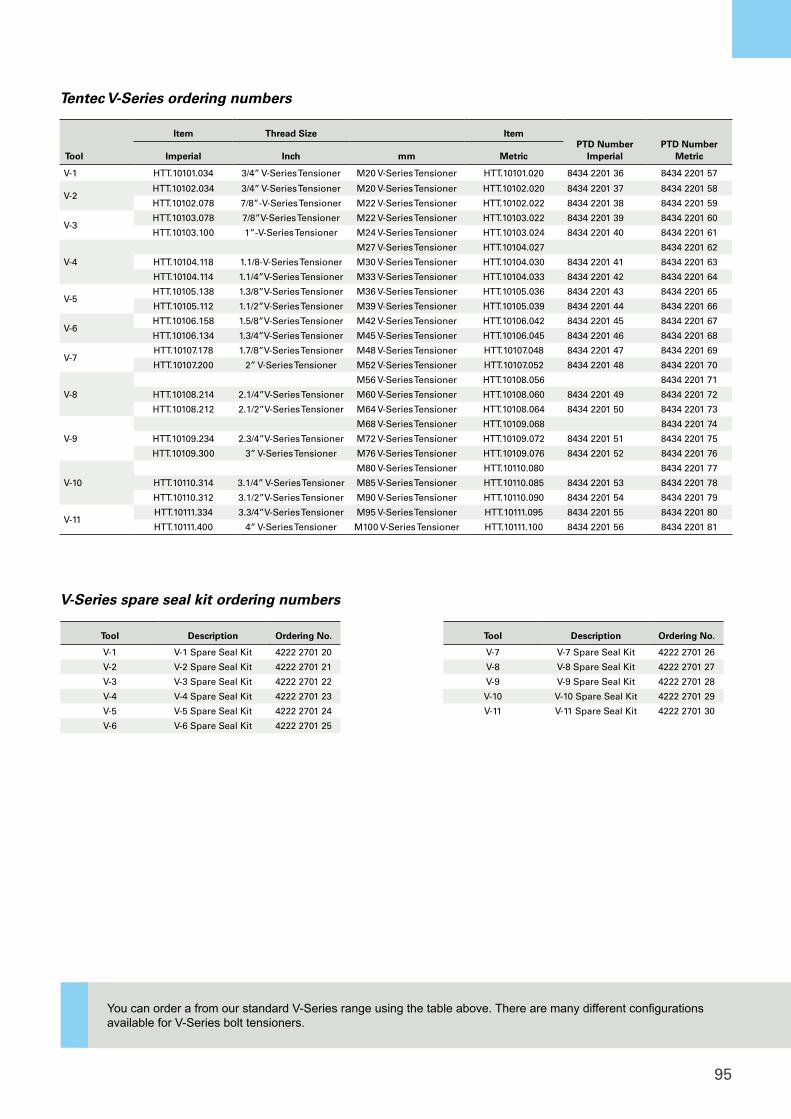
95
Tool
Item Thread Size ItemPTD Number
ImperialPTD Number
MetricImperial Inch mm Metric
V-1 HTT.10101.034 3/4” V-Series Tensioner M20 V-Series Tensioner HTT.10101.020 8434 2201 36 8434 2201 57
V-2HTT.10102.034 3/4” V-Series Tensioner M20 V-Series Tensioner HTT.10102.020 8434 2201 37 8434 2201 58
HTT.10102.078 7/8”-V-Series Tensioner M22 V-Series Tensioner HTT.10102.022 8434 2201 38 8434 2201 59
V-3HTT.10103.078 7/8”V-Series Tensioner M22 V-Series Tensioner HTT.10103.022 8434 2201 39 8434 2201 60
HTT.10103.100 1”-V-Series Tensioner M24 V-Series Tensioner HTT.10103.024 8434 2201 40 8434 2201 61
V-4
M27 V-Series Tensioner HTT.10104.027 8434 2201 62
HTT.10104.118 1.1/8-V-Series Tensioner M30 V-Series Tensioner HTT.10104.030 8434 2201 41 8434 2201 63
HTT.10104.114 1.1/4”V-Series Tensioner M33 V-Series Tensioner HTT.10104.033 8434 2201 42 8434 2201 64
V-5HTT.10105.138 1.3/8”V-Series Tensioner M36 V-Series Tensioner HTT.10105.036 8434 2201 43 8434 2201 65
HTT.10105.112 1.1/2”V-Series Tensioner M39 V-Series Tensioner HTT.10105.039 8434 2201 44 8434 2201 66
V-6HTT.10106.158 1.5/8”V-Series Tensioner M42 V-Series Tensioner HTT.10106.042 8434 2201 45 8434 2201 67
HTT.10106.134 1.3/4”V-Series Tensioner M45 V-Series Tensioner HTT.10106.045 8434 2201 46 8434 2201 68
V-7HTT.10107.178 1.7/8”V-Series Tensioner M48 V-Series Tensioner HTT.10107.048 8434 2201 47 8434 2201 69
HTT.10107.200 2” V-Series Tensioner M52 V-Series Tensioner HTT.10107.052 8434 2201 48 8434 2201 70
V-8
M56 V-Series Tensioner HTT.10108.056 8434 2201 71
HTT.10108.214 2.1/4”V-Series Tensioner M60 V-Series Tensioner HTT.10108.060 8434 2201 49 8434 2201 72
HTT.10108.212 2.1/2”V-Series Tensioner M64 V-Series Tensioner HTT.10108.064 8434 2201 50 8434 2201 73
V-9
M68 V-Series Tensioner HTT.10109.068 8434 2201 74
HTT.10109.234 2.3/4”V-Series Tensioner M72 V-Series Tensioner HTT.10109.072 8434 2201 51 8434 2201 75
HTT.10109.300 3” V-Series Tensioner M76 V-Series Tensioner HTT.10109.076 8434 2201 52 8434 2201 76
V-10
M80 V-Series Tensioner HTT.10110.080 8434 2201 77
HTT.10110.314 3.1/4” V-Series Tensioner M85 V-Series Tensioner HTT.10110.085 8434 2201 53 8434 2201 78
HTT.10110.312 3.1/2”V-Series Tensioner M90 V-Series Tensioner HTT.10110.090 8434 2201 54 8434 2201 79
V-11HTT.10111.334 3.3/4”V-Series Tensioner M95 V-Series Tensioner HTT.10111.095 8434 2201 55 8434 2201 80
HTT.10111.400 4” V-Series Tensioner M100 V-Series Tensioner HTT.10111.100 8434 2201 56 8434 2201 81
Tentec V-Series ordering numbers
Tool Description Ordering No.
V-1 V-1 Spare Seal Kit 4222 2701 20
V-2 V-2 Spare Seal Kit 4222 2701 21
V-3 V-3 Spare Seal Kit 4222 2701 22
V-4 V-4 Spare Seal Kit 4222 2701 23
V-5 V-5 Spare Seal Kit 4222 2701 24
V-6 V-6 Spare Seal Kit 4222 2701 25
Tool Description Ordering No.
V-7 V-7 Spare Seal Kit 4222 2701 26
V-8 V-8 Spare Seal Kit 4222 2701 27
V-9 V-9 Spare Seal Kit 4222 2701 28
V-10 V-10 Spare Seal Kit 4222 2701 29
V-11 V-11 Spare Seal Kit 4222 2701 30
V-Series spare seal kit ordering numbers
You can order a from our standard V-Series range using the table above. There are many different configurations available for V-Series bolt tensioners.
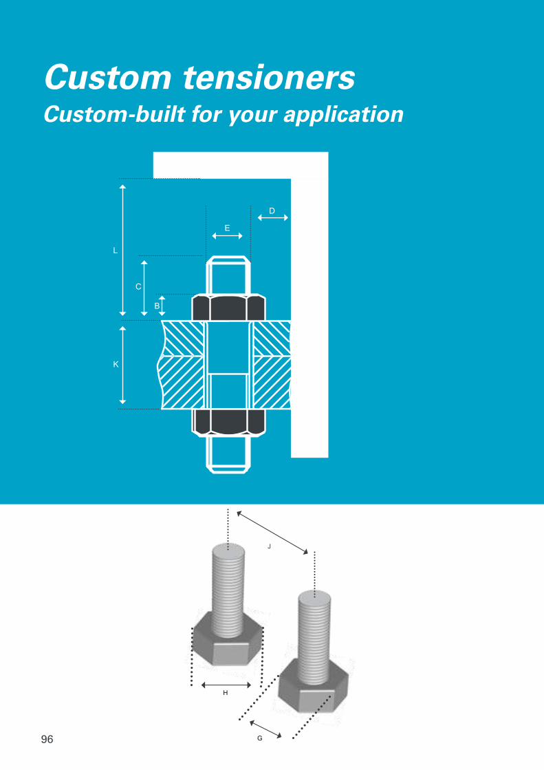
96
B
C
L
K
E
D
H
G
J
Custom tensionersCustom-built for your application

97
Tentec line of tensioners cover a great range of applications, but our in-house development team really shines when it comes to custom tensioner design. No matter the application, our team can get it done. By providing us with basic measurements, we can create the exact tensioner design for your application. All parts of a tensioner can be customized to cater for any special application. Common customization is requested to match thread pitch, bolt load requirements and Nut Rotating Socket height.
Customized sculpted bridgeBy customizing the bridge, we can make a tensioner that fits in between very close hexagon nuts.
Customized machined flatsCustomized machined flats to the rear of the tensioner to allow for tight weld
radius and tight applications.
Machined profileWe can machine profile, rear and sides to
adjust to a specific measurement.
Machined nut rotating socketProfiles can be reduced on the Nut
Rotating Socket to perfectly sit in between adjacent nuts.
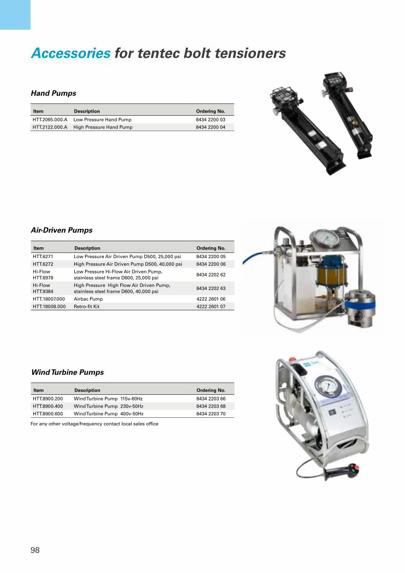
98
Item Description Ordering No.
HTT.2065.000.A Low Pressure Hand Pump 8434 2200 03
HTT.2122.000.A High Pressure Hand Pump 8434 2200 04
Hand Pumps
Accessories for tentec bolt tensioners
Item Description Ordering No.
HTT.6271 Low Pressure Air Driven Pump D500, 25,000 psi 8434 2200 05
HTT.6272 High Pressure Air Driven Pump D500, 40,000 psi 8434 2200 06
Hi-Flow HTT.6978
Low Pressure Hi-Flow Air Driven Pump, stainless steel frame D600, 25,000 psi
8434 2202 62
Hi-Flow HTT.9384
High Pressure High Flow Air Driven Pump, stainless steel frame D600, 40,000 psi
8434 2202 63
HTT.18007.000 Airbac Pump 4222 2601 06
HTT.18008.000 Retro-fit Kit 4222 2601 07
Item Description Ordering No.
HTT.8900.200 Wind Turbine Pump 115v-60Hz 8434 2203 66
HTT.8900.400 Wind Turbine Pump 230v-50Hz 8434 2203 68
HTT.8900.600 Wind Turbine Pump 400v-50Hz 8434 2203 70
Air-Driven Pumps
Wind Turbine Pumps
For any other voltage/frequency contact local sales office
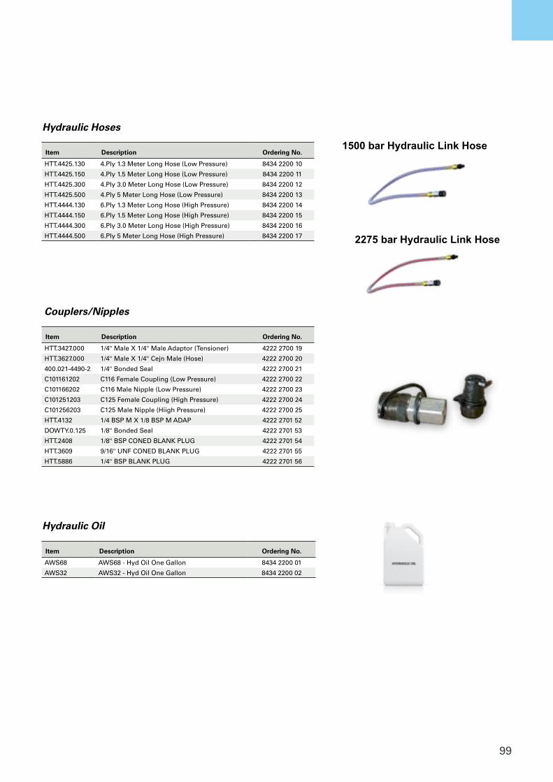
99
Item Description Ordering No.
AWS68 AWS68 - Hyd Oil One Gallon 8434 2200 01
AWS32 AWS32 - Hyd Oil One Gallon 8434 2200 02
Item Description Ordering No.
HTT.4425.130 4.Ply 1.3 Meter Long Hose (Low Pressure) 8434 2200 10
HTT.4425.150 4.Ply 1.5 Meter Long Hose (Low Pressure) 8434 2200 11
HTT.4425.300 4.Ply 3.0 Meter Long Hose (Low Pressure) 8434 2200 12
HTT.4425.500 4.Ply 5 Meter Long Hose (Low Pressure) 8434 2200 13
HTT.4444.130 6.Ply 1.3 Meter Long Hose (High Pressure) 8434 2200 14
HTT.4444.150 6.Ply 1.5 Meter Long Hose (High Pressure) 8434 2200 15
HTT.4444.300 6.Ply 3.0 Meter Long Hose (High Pressure) 8434 2200 16
HTT.4444.500 6.Ply 5 Meter Long Hose (High Pressure) 8434 2200 17
Item Description Ordering No.
HTT.3427.000 1/4" Male X 1/4" Male Adaptor (Tensioner) 4222 2700 19
HTT.3627.000 1/4" Male X 1/4" Cejn Male (Hose) 4222 2700 20
400.021-4490-2 1/4" Bonded Seal 4222 2700 21
C101161202 C116 Female Coupling (Low Pressure) 4222 2700 22
C101166202 C116 Male Nipple (Low Pressure) 4222 2700 23
C101251203 C125 Female Coupling (High Pressure) 4222 2700 24
C101256203 C125 Male Nipple (Hiigh Pressure) 4222 2700 25
HTT.4132 1/4 BSP M X 1/8 BSP M ADAP 4222 2701 52
DOWTY.0.125 1/8" Bonded Seal 4222 2701 53
HTT.2408 1/8" BSP CONED BLANK PLUG 4222 2701 54
HTT.3609 9/16" UNF CONED BLANK PLUG 4222 2701 55
HTT.5886 1/4" BSP BLANK PLUG 4222 2701 56
1500 bar Hydraulic Link Hose
2275 bar Hydraulic Link Hose
Hydraulic Oil
Couplers/Nipples
Hydraulic Hoses
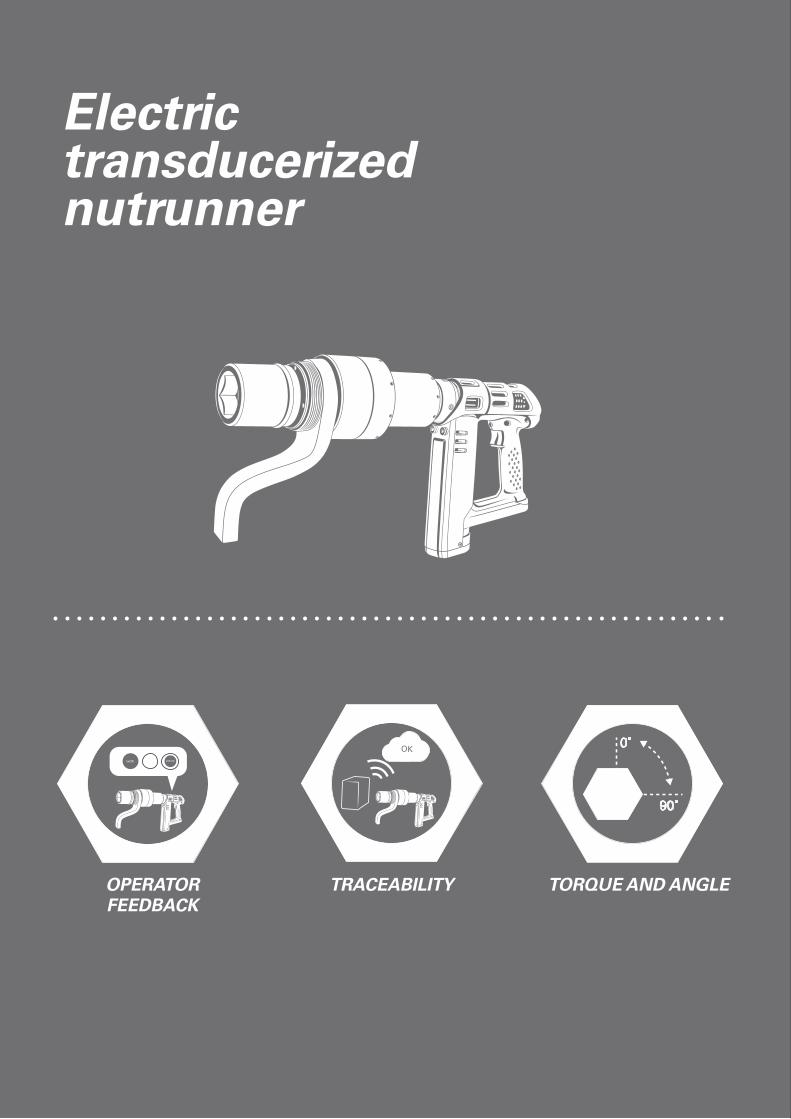
100
0˚
90˚
nxOK JOB OK
OK
OKOK
Electric transducerizednutrunner
OPERATOR FEEDBACK
TRACEABILITY TORQUE AND ANGLE
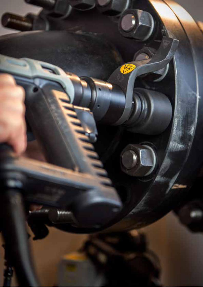
101
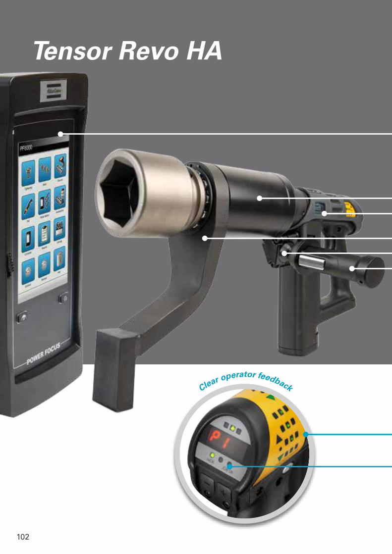
102
Clear operator feedback
Tensor Revo HA
E
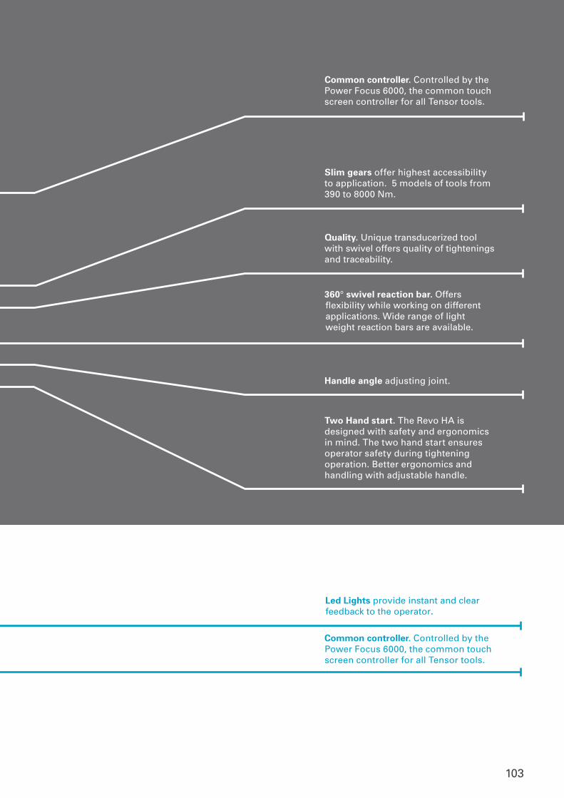
103
Common controller. Controlled by the Power Focus 6000, the common touch screen controller for all Tensor tools.
Slim gears offer highest accessibility to application. 5 models of tools from 390 to 8000 Nm.
Quality. Unique transducerized tool with swivel offers quality of tightenings and traceability.
360° swivel reaction bar. Offers flexibility while working on different applications. Wide range of light weight reaction bars are available.
Handle angle adjusting joint.
Two Hand start. The Revo HA is designed with safety and ergonomics in mind. The two hand start ensures operator safety during tightening operation. Better ergonomics and handling with adjustable handle.
Led Lights provide instant and clear feedback to the operator.
Common controller. Controlled by the Power Focus 6000, the common touch screen controller for all Tensor tools.

104
High accessIt is smaller, lighter and faster
CONTROLLER CASEREVO CASE
Traditional air and hydraulic tools have problems with noise, vibration and unproductive operation. Also, on most tools the operator can not see the tightening result. This leads to unnecessary investments in additional tools.
Highest accessibility With usability in focus, the Revo HA is designed with a slim gearbox and compact reaction bars with relatively low weight. It's also equipped with a socket release function that releases the socket and reaction bar from the joint after tightening is done.
Process quality The Revo HA is the first ever swiveling transducerized tool in this segment. It uses traceability, angle control and monitoring to assure perfect joint quality.
Faster tightening process These high torque models can operate at comparatively high speeds. With multi torque setting buttons and operator feedback on the display the tightening process is shortened.
Safe and ergonomic Two-handed start trigger makes it safer to operate. With the tool weight balanced out in two hands operator fatigue is reduced. The low vibration and noise level provides a much sounder and comfortable working environment. The controller case enables easy transport between stations and tasks.
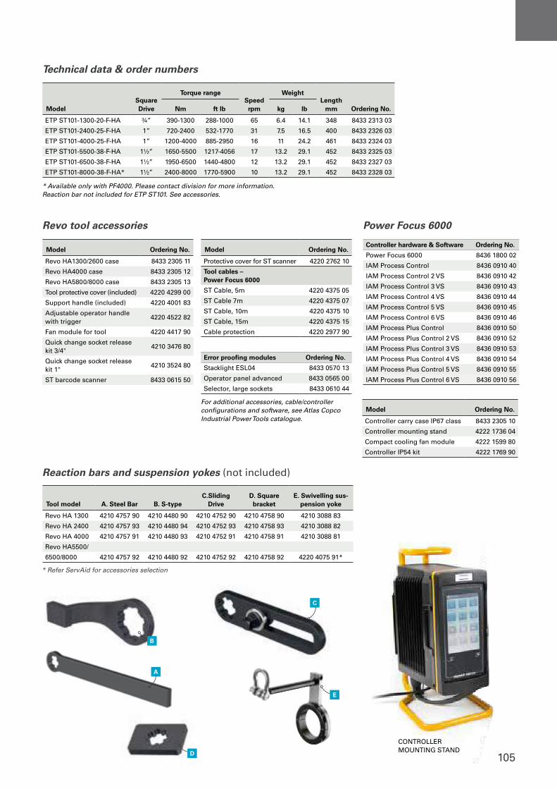
105
Technical data & order numbers
Revo tool accessories Power Focus 6000
Model Ordering No.
Revo HA1300/2600 case 8433 2305 11
Revo HA4000 case 8433 2305 12
Revo HA5800/8000 case 8433 2305 13
Tool protective cover (included) 4220 4299 00
Support handle (included) 4220 4001 83
Adjustable operator handle with trigger
4220 4522 82
Fan module for tool 4220 4417 90
Quick change socket release kit 3/4"
4210 3476 80
Quick change socket release kit 1"
4210 3524 80
ST barcode scanner 8433 0615 50
For additional accessories, cable/controller configurations and software, see Atlas Copco Industrial Power Tools catalogue.
* Available only with PF4000. Please contact division for more information.Reaction bar not included for ETP ST101. See accessories.
Model Ordering No.
Protective cover for ST scanner 4220 2762 10
Tool cables – Power Focus 6000
ST Cable, 5m 4220 4375 05
ST Cable 7m 4220 4375 07
ST Cable, 10m 4220 4375 10
ST Cable, 15m 4220 4375 15
Cable protection 4220 2977 90
Model Ordering No.
Controller carry case IP67 class 8433 2305 10
Controller mounting stand 4222 1736 04
Compact cooling fan module 4222 1599 80
Controller IP54 kit 4222 1769 90
Error proofing modules Ordering No.
Stacklight ESL04 8433 0570 13
Operator panel advanced 8433 0565 00
Selector, large sockets 8433 0610 44
Controller hardware & Software Ordering No.
Power Focus 6000 8436 1800 02
IAM Process Control 8436 0910 40
IAM Process Control 2 VS 8436 0910 42
IAM Process Control 3 VS 8436 0910 43
IAM Process Control 4 VS 8436 0910 44
IAM Process Control 5 VS 8436 0910 45
IAM Process Control 6 VS 8436 0910 46
IAM Process Plus Control 8436 0910 50
IAM Process Plus Control 2 VS 8436 0910 52
IAM Process Plus Control 3 VS 8436 0910 53
IAM Process Plus Control 4 VS 8436 0910 54
IAM Process Plus Control 5 VS 8436 0910 55
IAM Process Plus Control 6 VS 8436 0910 56
A
D
B
E
C
CONTROLLER MOUNTING STAND
ModelSquare Drive
Torque rangeSpeed rpm
WeightLength
mm Ordering No.Nm ft lb kg lb
ETP ST101-1300-20-F-HA ¾” 390-1300 288-1000 65 6.4 14.1 348 8433 2313 03
ETP ST101-2400-25-F-HA 1” 720-2400 532-1770 31 7.5 16.5 400 8433 2326 03
ETP ST101-4000-25-F-HA 1” 1200-4000 885-2950 16 11 24.2 461 8433 2324 03
ETP ST101-5500-38-F-HA 1½” 1650-5500 1217-4056 17 13.2 29.1 452 8433 2325 03
ETP ST101-6500-38-F-HA 1½” 1950-6500 1440-4800 12 13.2 29.1 452 8433 2327 03
ETP ST101-8000-38-F-HA* 1½” 2400-8000 1770-5900 10 13.2 29.1 452 8433 2328 03
Reaction bars and suspension yokes (not included)
* Refer ServAid for accessories selection
Tool model A. Steel Bar B. S-typeC.Sliding
DriveD. Square bracket
E. Swivelling sus-pension yoke
Revo HA 1300 4210 4757 90 4210 4480 90 4210 4752 90 4210 4758 90 4210 3088 83
Revo HA 2400 4210 4757 93 4210 4480 94 4210 4752 93 4210 4758 93 4210 3088 82
Revo HA 4000 4210 4757 91 4210 4480 93 4210 4752 91 4210 4758 91 4210 3088 81
Revo HA5500/
6500/8000 4210 4757 92 4210 4480 92 4210 4752 92 4210 4758 92 4220 4075 91*
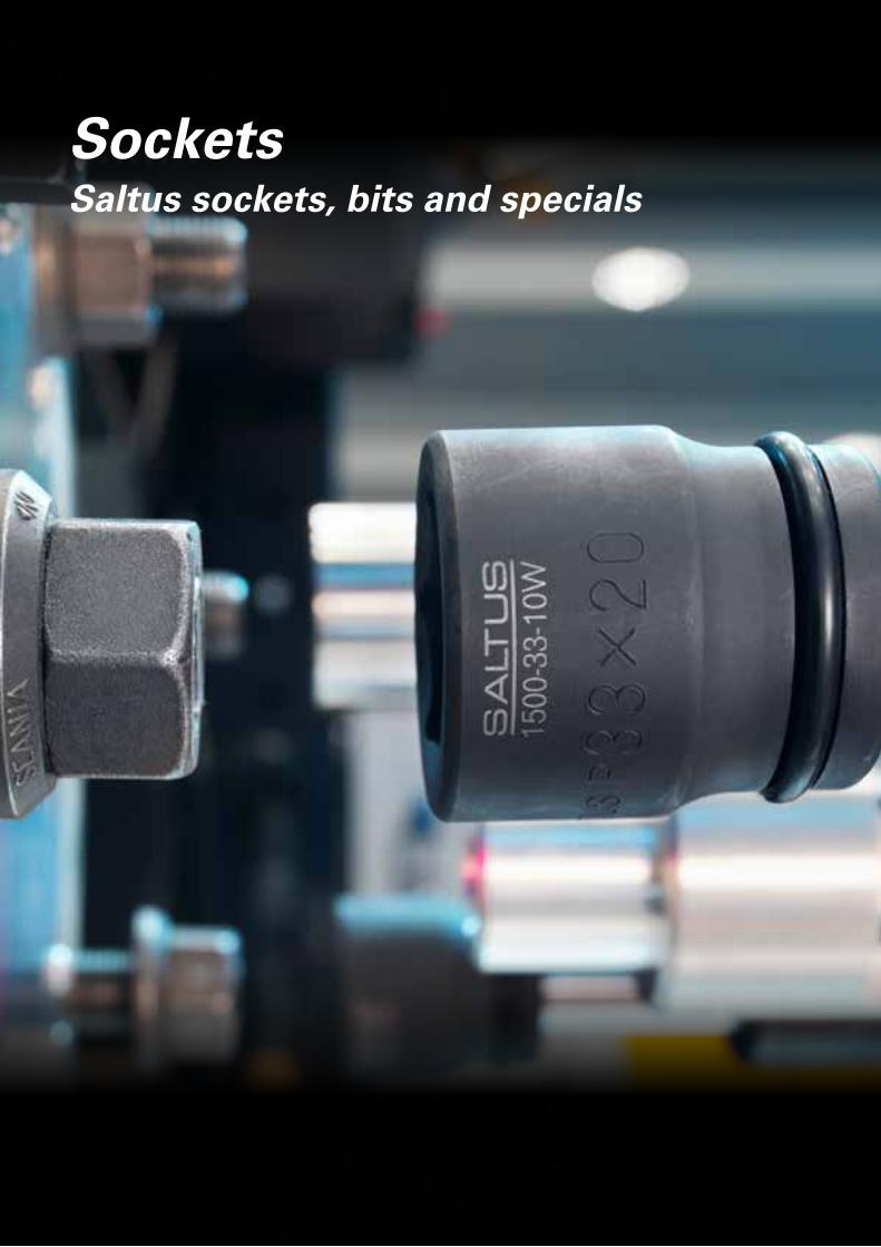
106
SocketsSaltus sockets, bits and specials
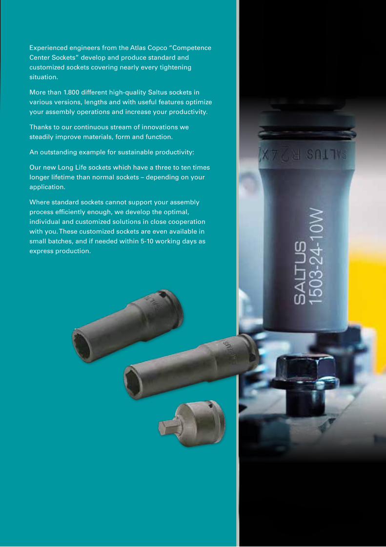
107
Experienced engineers from the Atlas Copco “Competence
Center Sockets” develop and produce standard and
customized sockets covering nearly every tightening
situation.
More than 1.800 different high-quality Saltus sockets in
various versions, lengths and with useful features optimize
your assembly operations and increase your productivity.
Thanks to our continuous stream of innovations we
steadily improve materials, form and function.
An outstanding example for sustainable productivity:
Our new Long Life sockets which have a three to ten times
longer lifetime than normal sockets – depending on your
application.
Where standard sockets cannot support your assembly
process efficiently enough, we develop the optimal,
individual and customized solutions in close cooperation
with you. These customized sockets are even available in
small batches, and if needed within 5-10 working days as
express production.
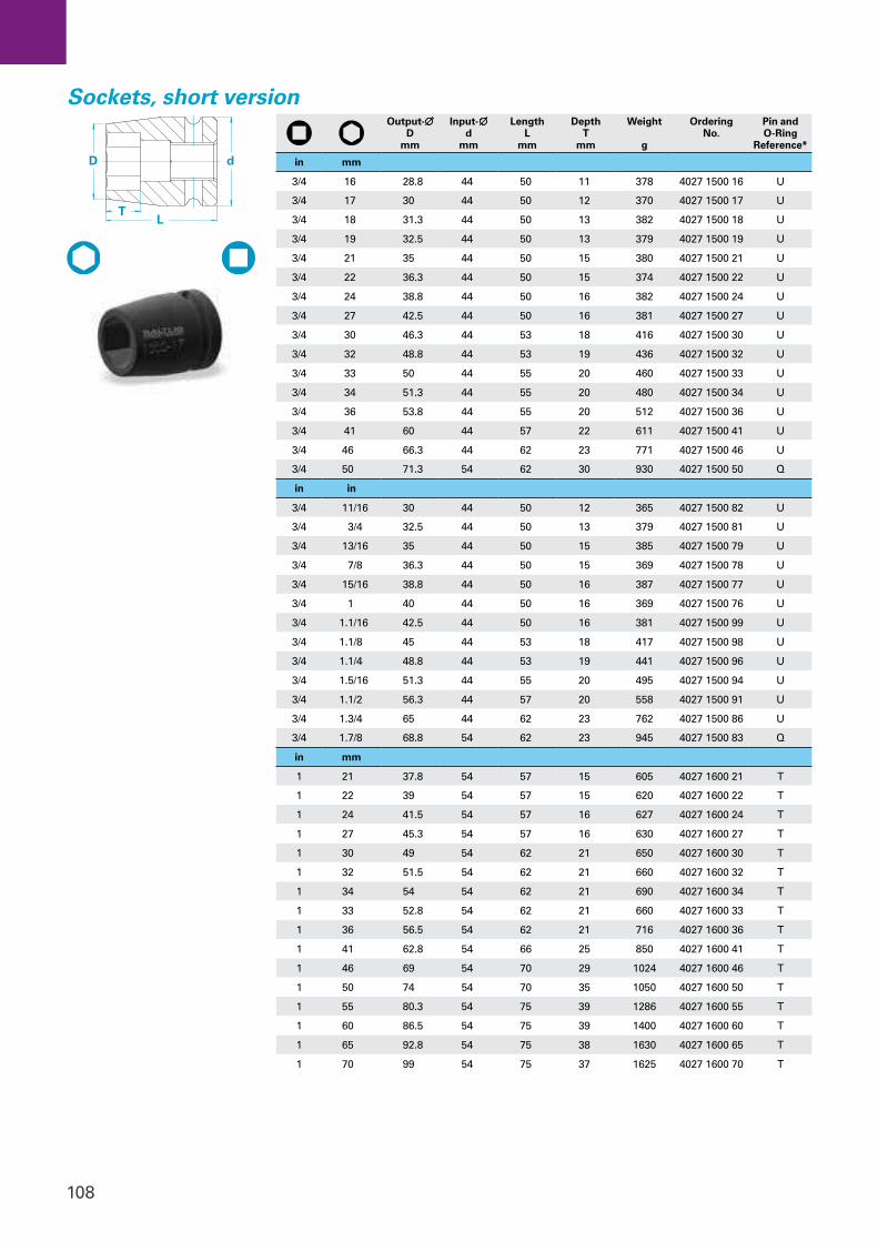
108
Sockets, short versionOutput-∅
D mm
Input- ∅ d
mm
Length L
mm
Depth T
mm
Weight g
Ordering No.
Pin and O-Ring
Reference*
in mm
3/4 16 28.8 44 50 11 378 4027 1500 16 U
3/4 17 30 44 50 12 370 4027 1500 17 U
3/4 18 31.3 44 50 13 382 4027 1500 18 U
3/4 19 32.5 44 50 13 379 4027 1500 19 U
3/4 21 35 44 50 15 380 4027 1500 21 U
3/4 22 36.3 44 50 15 374 4027 1500 22 U
3/4 24 38.8 44 50 16 382 4027 1500 24 U
3/4 27 42.5 44 50 16 381 4027 1500 27 U
3/4 30 46.3 44 53 18 416 4027 1500 30 U
3/4 32 48.8 44 53 19 436 4027 1500 32 U
3/4 33 50 44 55 20 460 4027 1500 33 U
3/4 34 51.3 44 55 20 480 4027 1500 34 U
3/4 36 53.8 44 55 20 512 4027 1500 36 U
3/4 41 60 44 57 22 611 4027 1500 41 U
3/4 46 66.3 44 62 23 771 4027 1500 46 U
3/4 50 71.3 54 62 30 930 4027 1500 50 Q
in in
3/4 11/16 30 44 50 12 365 4027 1500 82 U
3/4 3/4 32.5 44 50 13 379 4027 1500 81 U
3/4 13/16 35 44 50 15 385 4027 1500 79 U
3/4 7/8 36.3 44 50 15 369 4027 1500 78 U
3/4 15/16 38.8 44 50 16 387 4027 1500 77 U
3/4 1 40 44 50 16 369 4027 1500 76 U
3/4 1.1/16 42.5 44 50 16 381 4027 1500 99 U
3/4 1.1/8 45 44 53 18 417 4027 1500 98 U
3/4 1.1/4 48.8 44 53 19 441 4027 1500 96 U
3/4 1.5/16 51.3 44 55 20 495 4027 1500 94 U
3/4 1.1/2 56.3 44 57 20 558 4027 1500 91 U
3/4 1.3/4 65 44 62 23 762 4027 1500 86 U
3/4 1.7/8 68.8 54 62 23 945 4027 1500 83 Q
in mm
1 21 37.8 54 57 15 605 4027 1600 21 T
1 22 39 54 57 15 620 4027 1600 22 T
1 24 41.5 54 57 16 627 4027 1600 24 T
1 27 45.3 54 57 16 630 4027 1600 27 T
1 30 49 54 62 21 650 4027 1600 30 T
1 32 51.5 54 62 21 660 4027 1600 32 T
1 34 54 54 62 21 690 4027 1600 34 T
1 33 52.8 54 62 21 660 4027 1600 33 T
1 36 56.5 54 62 21 716 4027 1600 36 T
1 41 62.8 54 66 25 850 4027 1600 41 T
1 46 69 54 70 29 1024 4027 1600 46 T
1 50 74 54 70 35 1050 4027 1600 50 T
1 55 80.3 54 75 39 1286 4027 1600 55 T
1 60 86.5 54 75 39 1400 4027 1600 60 T
1 65 92.8 54 75 38 1630 4027 1600 65 T
1 70 99 54 75 37 1625 4027 1600 70 T
d
L T
D
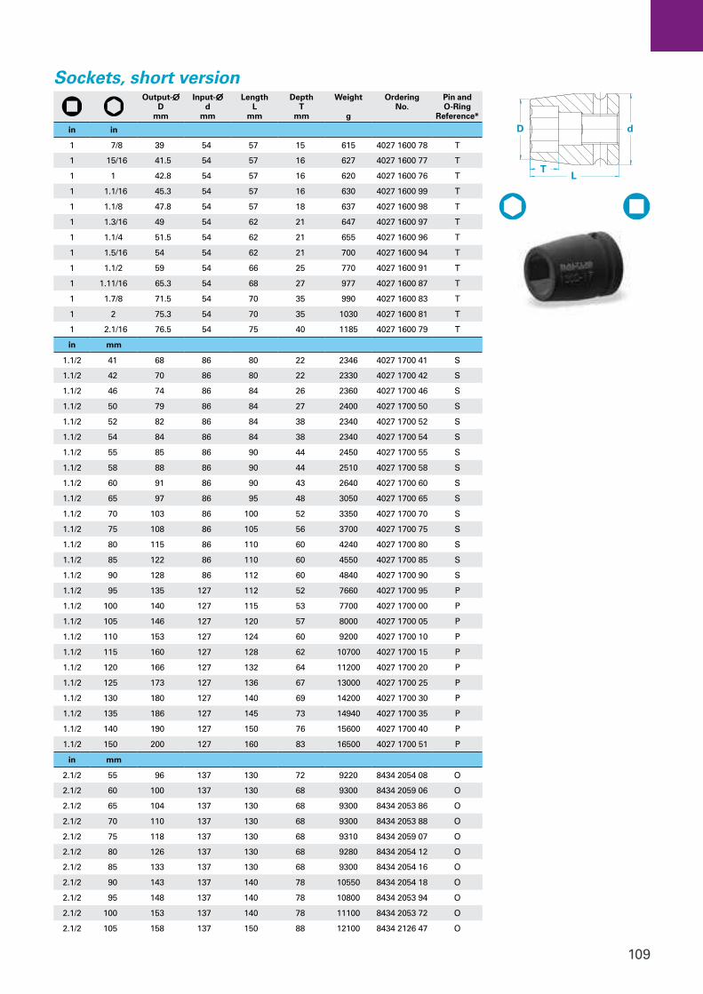
109
Sockets, short versionOutput-∅
D mm
Input- ∅ d
mm
Length L
mm
Depth T
mm
Weight g
Ordering No.
Pin and O-Ring
Reference*
in in
1 7/8 39 54 57 15 615 4027 1600 78 T
1 15/16 41.5 54 57 16 627 4027 1600 77 T
1 1 42.8 54 57 16 620 4027 1600 76 T
1 1.1/16 45.3 54 57 16 630 4027 1600 99 T
1 1.1/8 47.8 54 57 18 637 4027 1600 98 T
1 1.3/16 49 54 62 21 647 4027 1600 97 T
1 1.1/4 51.5 54 62 21 655 4027 1600 96 T
1 1.5/16 54 54 62 21 700 4027 1600 94 T
1 1.1/2 59 54 66 25 770 4027 1600 91 T
1 1.11/16 65.3 54 68 27 977 4027 1600 87 T
1 1.7/8 71.5 54 70 35 990 4027 1600 83 T
1 2 75.3 54 70 35 1030 4027 1600 81 T
1 2.1/16 76.5 54 75 40 1185 4027 1600 79 T
in mm
1.1/2 41 68 86 80 22 2346 4027 1700 41 S
1.1/2 42 70 86 80 22 2330 4027 1700 42 S
1.1/2 46 74 86 84 26 2360 4027 1700 46 S
1.1/2 50 79 86 84 27 2400 4027 1700 50 S
1.1/2 52 82 86 84 38 2340 4027 1700 52 S
1.1/2 54 84 86 84 38 2340 4027 1700 54 S
1.1/2 55 85 86 90 44 2450 4027 1700 55 S
1.1/2 58 88 86 90 44 2510 4027 1700 58 S
1.1/2 60 91 86 90 43 2640 4027 1700 60 S
1.1/2 65 97 86 95 48 3050 4027 1700 65 S
1.1/2 70 103 86 100 52 3350 4027 1700 70 S
1.1/2 75 108 86 105 56 3700 4027 1700 75 S
1.1/2 80 115 86 110 60 4240 4027 1700 80 S
1.1/2 85 122 86 110 60 4550 4027 1700 85 S
1.1/2 90 128 86 112 60 4840 4027 1700 90 S
1.1/2 95 135 127 112 52 7660 4027 1700 95 P
1.1/2 100 140 127 115 53 7700 4027 1700 00 P
1.1/2 105 146 127 120 57 8000 4027 1700 05 P
1.1/2 110 153 127 124 60 9200 4027 1700 10 P
1.1/2 115 160 127 128 62 10700 4027 1700 15 P
1.1/2 120 166 127 132 64 11200 4027 1700 20 P
1.1/2 125 173 127 136 67 13000 4027 1700 25 P
1.1/2 130 180 127 140 69 14200 4027 1700 30 P
1.1/2 135 186 127 145 73 14940 4027 1700 35 P
1.1/2 140 190 127 150 76 15600 4027 1700 40 P
1.1/2 150 200 127 160 83 16500 4027 1700 51 P
in mm
2.1/2 55 96 137 130 72 9220 8434 2054 08 O
2.1/2 60 100 137 130 68 9300 8434 2059 06 O
2.1/2 65 104 137 130 68 9300 8434 2053 86 O
2.1/2 70 110 137 130 68 9300 8434 2053 88 O
2.1/2 75 118 137 130 68 9310 8434 2059 07 O
2.1/2 80 126 137 130 68 9280 8434 2054 12 O
2.1/2 85 133 137 130 68 9300 8434 2054 16 O
2.1/2 90 143 137 140 78 10550 8434 2054 18 O
2.1/2 95 148 137 140 78 10800 8434 2053 94 O
2.1/2 100 153 137 140 78 11100 8434 2053 72 O
2.1/2 105 158 137 150 88 12100 8434 2126 47 O
d
L T
D
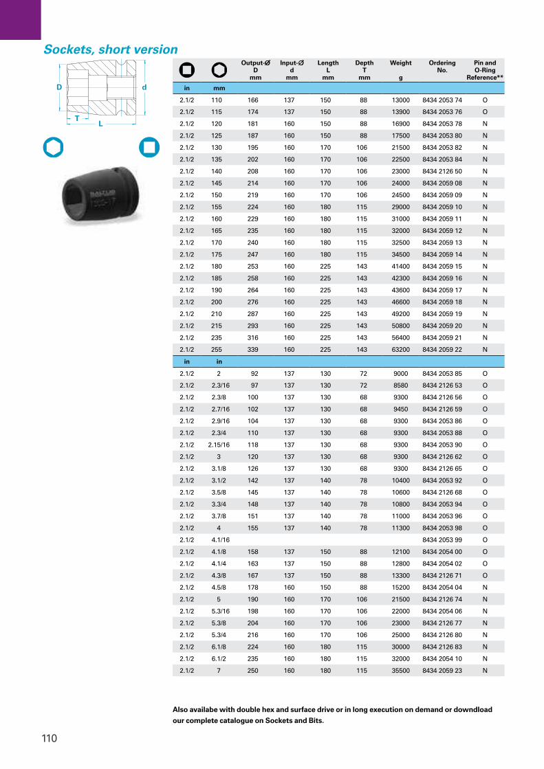
110
d
L T
D
Output-∅ D
mm
Input- ∅ d
mm
Length L
mm
Depth T
mm
Weight g
Ordering No.
Pin and O-Ring
Reference**
in mm
2.1/2 110 166 137 150 88 13000 8434 2053 74 O
2.1/2 115 174 137 150 88 13900 8434 2053 76 O
2.1/2 120 181 160 150 88 16900 8434 2053 78 N
2.1/2 125 187 160 150 88 17500 8434 2053 80 N
2.1/2 130 195 160 170 106 21500 8434 2053 82 N
2.1/2 135 202 160 170 106 22500 8434 2053 84 N
2.1/2 140 208 160 170 106 23000 8434 2126 50 N
2.1/2 145 214 160 170 106 24000 8434 2059 08 N
2.1/2 150 219 160 170 106 24500 8434 2059 09 N
2.1/2 155 224 160 180 115 29000 8434 2059 10 N
2.1/2 160 229 160 180 115 31000 8434 2059 11 N
2.1/2 165 235 160 180 115 32000 8434 2059 12 N
2.1/2 170 240 160 180 115 32500 8434 2059 13 N
2.1/2 175 247 160 180 115 34500 8434 2059 14 N
2.1/2 180 253 160 225 143 41400 8434 2059 15 N
2.1/2 185 258 160 225 143 42300 8434 2059 16 N
2.1/2 190 264 160 225 143 43600 8434 2059 17 N
2.1/2 200 276 160 225 143 46600 8434 2059 18 N
2.1/2 210 287 160 225 143 49200 8434 2059 19 N
2.1/2 215 293 160 225 143 50800 8434 2059 20 N
2.1/2 235 316 160 225 143 56400 8434 2059 21 N
2.1/2 255 339 160 225 143 63200 8434 2059 22 N
in in
2.1/2 2 92 137 130 72 9000 8434 2053 85 O
2.1/2 2.3/16 97 137 130 72 8580 8434 2126 53 O
2.1/2 2.3/8 100 137 130 68 9300 8434 2126 56 O
2.1/2 2.7/16 102 137 130 68 9450 8434 2126 59 O
2.1/2 2.9/16 104 137 130 68 9300 8434 2053 86 O
2.1/2 2.3/4 110 137 130 68 9300 8434 2053 88 O
2.1/2 2.15/16 118 137 130 68 9300 8434 2053 90 O
2.1/2 3 120 137 130 68 9300 8434 2126 62 O
2.1/2 3.1/8 126 137 130 68 9300 8434 2126 65 O
2.1/2 3.1/2 142 137 140 78 10400 8434 2053 92 O
2.1/2 3.5/8 145 137 140 78 10600 8434 2126 68 O
2.1/2 3.3/4 148 137 140 78 10800 8434 2053 94 O
2.1/2 3.7/8 151 137 140 78 11000 8434 2053 96 O
2.1/2 4 155 137 140 78 11300 8434 2053 98 O
2.1/2 4.1/16 8434 2053 99 O
2.1/2 4.1/8 158 137 150 88 12100 8434 2054 00 O
2.1/2 4.1/4 163 137 150 88 12800 8434 2054 02 O
2.1/2 4.3/8 167 137 150 88 13300 8434 2126 71 O
2.1/2 4.5/8 178 160 150 88 15200 8434 2054 04 N
2.1/2 5 190 160 170 106 21500 8434 2126 74 N
2.1/2 5.3/16 198 160 170 106 22000 8434 2054 06 N
2.1/2 5.3/8 204 160 170 106 23000 8434 2126 77 N
2.1/2 5.3/4 216 160 170 106 25000 8434 2126 80 N
2.1/2 6.1/8 224 160 180 115 30000 8434 2126 83 N
2.1/2 6.1/2 235 160 180 115 32000 8434 2054 10 N
2.1/2 7 250 160 180 115 35500 8434 2059 23 N
Also availabe with double hex and surface drive or in long execution on demand or downdload
our complete catalogue on Sockets and Bits.
Sockets, short version
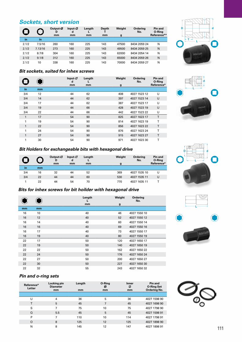
111
Pin and o-ring sets
d
L T
D
Sockets, short versionOutput-∅
D mm
Input- ∅ d
mm
Length L
mm
Depth T
mm
Weight g
Ordering No.
Pin and O-Ring
Reference**
in in
2.1/2 7.5/16 260 160 225 143 47500 8434 2059 24 N
2.1/2 7.13/16 273 160 225 143 49500 8434 2059 25 N
2.1/2 8.7/8 304 160 225 143 62000 8434 2054 14 N
2.1/2 9.1/8 312 160 225 143 65000 8434 2059 26 N
2.1/2 10 338 160 225 143 70000 8434 2059 27 N
Input- ∅ d
mm
Length L
mm
Weight g
Ordering No.
Pin and O-Ring
Reference*
in mm
3/4 12 44 62 408 4027 1523 12 U
3/4 14 44 62 397 4027 1523 14 U
3/4 17 44 62 387 4027 1523 17 U
3/4 19 44 66 428 4027 1523 19 U
3/4 22 44 66 442 4027 1523 22 U
1 17 54 90 825 4027 1623 17 T
1 19 54 90 814 4027 1623 19 T
1 22 54 90 856 4027 1623 22 T
1 24 54 90 876 4027 1623 24 T
1 27 54 90 915 4027 1623 27 T
1 30 54 90 971 4027 1623 30 T
Bit sockets, suited for inhex screws
d
L
Bit Holders for exchangeable bits with hexagonal drive
Output-∅ D
mm
Input- ∅ d
mm
Length L
mm
Weight g
Ordering No.
Pin and O-Ring
Reference*
in mm
3/4 16 32 44 52 369 4027 1535 10 U
3/4 22 44 44 60 530 4027 1535 11 U
1 22 44 54 70 770 4027 1635 11 T
d D
L
Reference* Letter
Locking pin Diameter
mm
Length
mm
O-Ring ∅
mm
Inner ∅
mm
Pin and O-Ring Set
Ordering No.
U 4 36 5 36 4027 1598 90
T 5 45 7 45 4027 1698 90
S 7 75 10 75 4027 1798 90
Q 5.5 45 5 45 4027 1598 91
P 7 110 10 114 4027 1798 91
O 8 125 12 125 4027 1898 90
N 8 145 12 147 4027 1898 91
Length L
mm
Weight g
Ordering No.
mm mm
16 10 40 46 4027 1550 10
16 12 40 52 4027 1550 12
16 14 40 60 4027 1550 14
16 16 40 69 4027 1550 16
16 17 40 73 4027 1550 17
16 19 40 80 4027 1550 19
22 17 50 120 4027 1650 17
22 19 50 140 4027 1650 19
22 22 50 162 4027 1650 22
22 24 50 176 4027 1650 24
22 27 50 200 4027 1650 27
22 30 50 227 4027 1650 30
22 32 55 243 4027 1650 32
L
Bits for inhex screws for bit hoilder with hexagonal drive
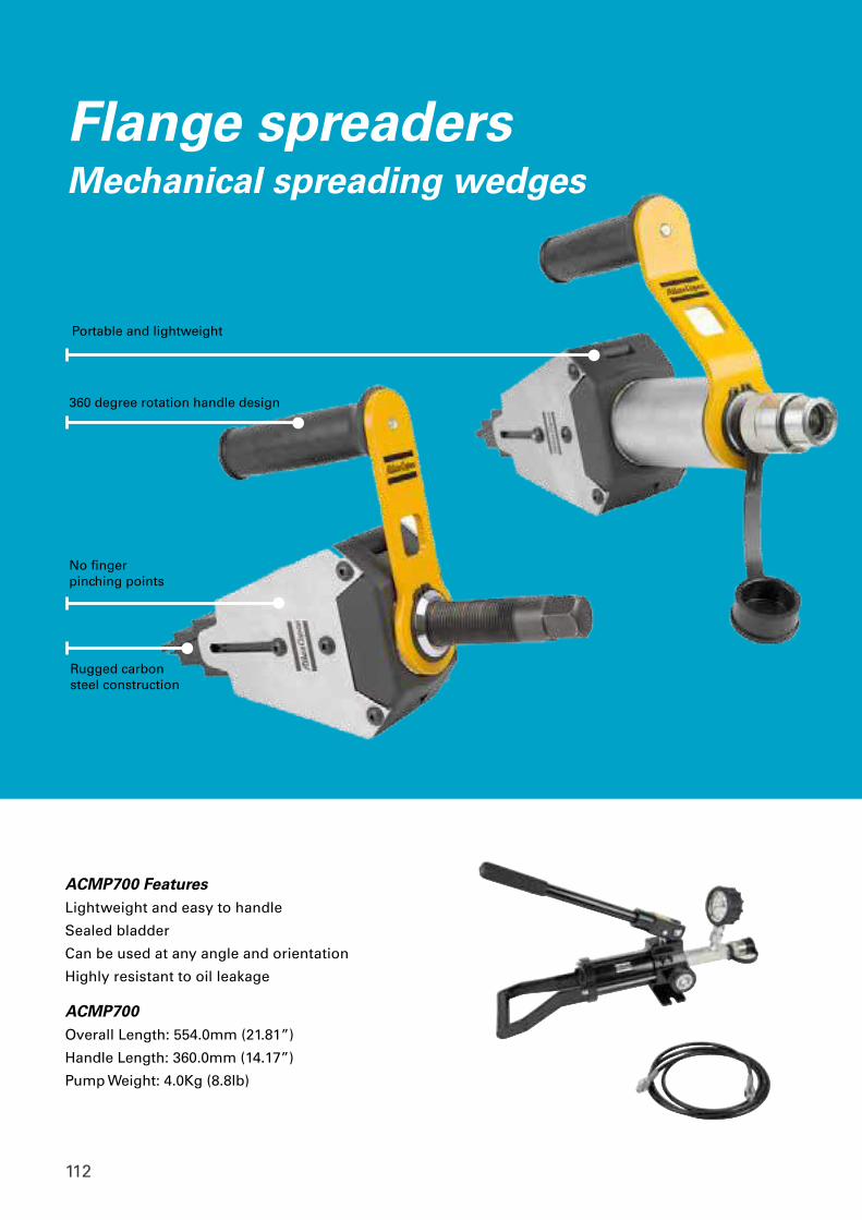
112
No fingerpinching points
Rugged carbon steel construction
Portable and lightweight
360 degree rotation handle design
Flange spreadersMechanical spreading wedges
ACMP700 Features Lightweight and easy to handle
Sealed bladder
Can be used at any angle and orientation
Highly resistant to oil leakage
ACMP700Overall Length: 554.0mm (21.81”)
Handle Length: 360.0mm (14.17”)
Pump Weight: 4.0Kg (8.8lb)

113
Portable and lightweight
360 degree rotation handle design
No finger pinching points
Rugged carbon steel construction
High power to weight ratio
Revolving handle
No finger pinching points
ACMS08T features ACHS14T features
Kit contents1 x ACMS08T wedgehead1 x 203 N m (150 ft lb) torque wrench with 22 mm socket1 x Safety block2 x Step blocks2 x Screws for step block1 x Lanyard1 x Allen key1 x Instruction manual1 x Polycarbonate carrying case
Capabilities8T spreading force from 180Nm (133ft.lb) of torque
Spreads: 6.0mm – 63.7mm(0.24” - 2.5”) (without stepped blocks)
Spreads: 60.0mm – 86.7mm (2.4” - 3.4”) (with stepped blocks)
(0.24” - 1.28”) spread using only 1st step
Capabilities14T spread force from 10,000psi (700 Bar) Hydraulic pressure
Spreads: 6.0mm – 63.7mm(0.24” - 2.5”) (without stepped blocks)
Spreads: 60.0mm – 86.7mm (2.4” - 3.4”) (with stepped blocks)
Kit contents1 x ACHS14T wedgehead c/w hydraulic cylinder1 x Lanyard1 x Allen key1 x Safety block2 x Step block2 x Screws for step blocks 1 x Instruction manual 1 x Polycarbonate carrying case
Part No. Product Description
8434 2058 04 Hydraulic Pump ACMP700 Manual
8434 2058 05 Flange Spreader ACMS08T Mechanical
8434 2058 06 Flange Spreader ACHS14T Hydraulic
8434 2058 07 Hose Kit Single Line 700 bar 4mtr
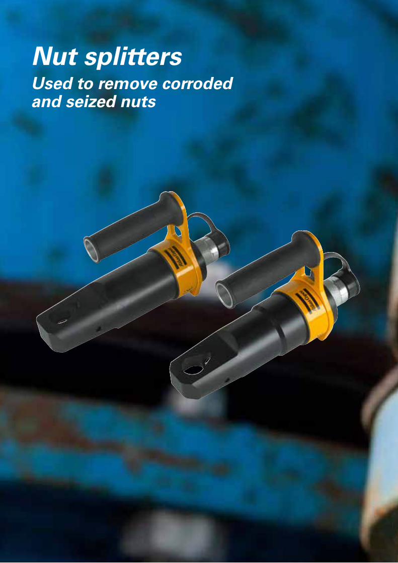
114
Nut splittersUsed to remove corroded and seized nuts
115
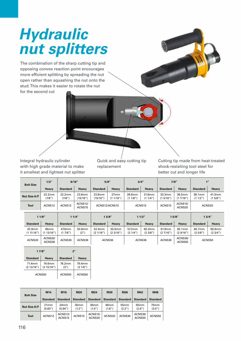
116
Hydraulic nut splitters
Bolt Size1/2” 9/16” 5/8” 3/4” 7/8” 1”
Heavy Standard Heavy Standard Heavy Standard Heavy Standard Heavy Standard Heavy
Nut Size A/F22.2mm
(7/8”)22.2mm
(7/8”)23.8mm(15/16”)
23.8mm(15/16”)
27mm(1 1/16”)
28.6mm(1 1/8”)
31.8mm(1 1/4”)
33.3mm(1 5/16”)
36.5mm(1 7/16”)
38.1mm(1 1/2”)
41.3mm(1 5/8”)
Tool ACNS12 ACNS12ACNS12/ACNS15
ACNS12/ACN515 ACNS15 ACNS15ACNS15/ACNS20
ACNS20
1 1/8” 1 1/4” 1 3/8” 1 1/2” 1 5/8” 1 3/4”
Standard Heavy Standard Heavy Standard Heavy Standard Heavy Standard Heavy Standard Heavy
42.9mm(1 11/16”)
46mm(1 13/16”)
47.6mm(1 7/8”)
50.8mm(2”)
52.4mm(2 1/16”)
55.6mm(2 3/16”)
57.2mm(2 1/4”)
60.3mm(2 3/8”)
61.9mm(2 7/16”)
65.1mm(2 9/16”)
66.7mm(2 5/8”)
69.9mm(2 3/4”)
ACNS20ACNS20/ACNS36
ACNS36 ACNS36 ACNS36 ACNS36 ACNS36ACNS36/ACNS50
ACNS50
1 7/8” 2”
Standard Heavy Standard Heavy
71.4mm(2 13/16”)
74.6mm(2 15/16”)
76.2mm(3”)
79.4mm(3 1/8”)
ACNS50 ACNS50 ACNS50
Bolt SizeM14 M16 M20 M24 M30 M36 M42 M48
Standard Standard Standard Standard Standard Standard Standard Standard
Nut Size A/F21mm(0.83”)
24mm(0.94”)
30mm(1.2”)
36mm(1.4”)
46mm(1.8”)
55mm(2.2”)
65mm(2.6”)
75mm(3.0”)
Tool ACNS12ACNS12/ACNS15
ACNS15ACNS15/ACNS20
ACNS20 ACNS36ACNS36/ACNS50
ACNS50
Integral hydraulic cylinder with high grade material to make it smallest and lightest nut splitter
Quick and easy cutting tip replacement
Cutting tip made from heat-treated shock-resisiting tool steel for better cut and longer life
The combination of the sharp cutting tip and opposing convex reaction point encourages more efficient splitting by spreading the nut open rather than squashing the nut onto the stud. This makes it easier to rotate the nut for the second cut
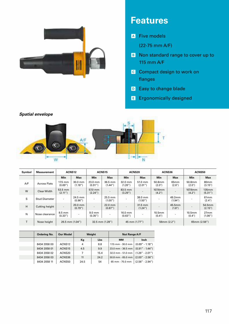
117
Symbol Measurement ACNS12 ACNS15 ACNS20 ACNS36 ACNS50
Min Max Min Max Min Max Min Max Min Max
A/F Across Flats 17.5 mm(0.69”)
30.0 mm(1.18”)
23.0 mm(0.91”)
36.5 mm(1.44”)
32.0 mm(1.26”)
51.0 mm(2.01”)
50.8mm(2.0")
65mm(2.6")
50.8mm(2.0")
80mm(3.15")
W Clear Width 53.5 mm(2.11”) - 57.0 mm
(2.24”) - 83.5 mm(3.29”) - 107.6mm
(4.2") - 107.6mm(4.2")
135mm(5.31”)
S Stud Diameter - 24.5 mm(0.96”) - 25.5 mm
(1.00”) - 38.0 mm(1.50”) - 49.2mm
(1.94") - 61mm(2.4")
H Cutting height - 20.0 mm(0.79”) - 22.0 mm
(0.87”) - 31.5 mm(1.24”) - 45.5mm
(1.8") - 54.5mm(2.15")
N Nose clearance 8.5 mm(0.33”) - 9.0 mm
(0.35”) - 16.0 mm(0.63”) - 10.5mm
(0.4") - 10.5mm(0.4")
27mm(1.06”)
T Nose height 26.5 mm (1.04”) 32.5 mm (1.28”) 45 mm (1.77”) 56mm (2.2”) 65mm (2.56”)
Ordering No. Our Model Weight Nut Range A/F
Kg Lbs MM Inch
8434 2058 00 ACNS12 4 8.8 17.5 mm - 30.0 mm (0.69” - 1.18”)
8434 2058 01 ACNS15 4.5 9.9 23.0 mm - 36.5 mm (0.91” - 1.44”)
8434 2058 02 ACNS20 7 15.4 32.0 mm - 51.0 mm (1.26” - 2.01”)
8434 2058 03 ACNS36 11 24.2 50.8 mm - 65.0 mm (2.00” - 2.56”)
8434 2058 11 ACNS50 24.5 54 65 mm - 75.0 mm (2.56” - 2.94”)
Spatial envelope
Bolt SizeM14 M16 M20 M24 M30 M36 M42 M48
Standard Standard Standard Standard Standard Standard Standard Standard
Nut Size A/F21mm(0.83”)
24mm(0.94”)
30mm(1.2”)
36mm(1.4”)
46mm(1.8”)
55mm(2.2”)
65mm(2.6”)
75mm(3.0”)
Tool ACNS12ACNS12/ACNS15
ACNS15ACNS15/ACNS20
ACNS20 ACNS36ACNS36/ACNS50
ACNS50
A Five models
(22-75 mm A/F)
B Non standard range to cover up to
115 mm A/F
C Compact design to work on
flanges
D Easy to change blade
E Ergonomically designed
Features

118
Type Name Ordernumber
Reports ToolsNet 8 - 1 spindle 8092 1710 01Reports ToolsNet 8 - 3 spindles 8092 1710 03Reports ToolsNet 8 - 5 spindles 8092 1710 05Reports ToolsNet 8 - 10 spindles 8092 1710 10Reports ToolsNet 8 - 25 spindles 8092 1710 25Reports ToolsNet 8 - 50 spindles 8092 1710 50Reports ToolsNet 8 - 75 spindles 8092 1710 75Reports ToolsNet 8 - 125 spindles 8092 1710 80Reports ToolsNet 8 - 225 spindles 8092 1710 85Reports ToolsNet 8 - 350 spindles 8092 1710 90Reports ToolsNet 8 - 500 spindles 8092 1710 95Reports ToolsNet 8 - 1000 spindles 8092 1710 00Alerts ToolsNet 8 - 5 spindles 8092 1711 05Alerts ToolsNet 8 - 10 spindles 8092 1711 10Alerts ToolsNet 8 - 25 spindles 8092 1711 25Alerts ToolsNet 8 - 50 spindles 8092 1711 50Alerts ToolsNet 8 - 75 spindles 8092 1711 75Alerts ToolsNet 8 - 125 spindles 8092 1711 80Alerts ToolsNet 8 - 225 spindles 8092 1711 85Alerts ToolsNet 8 - 350 spindles 8092 1711 90Alerts ToolsNet 8 - 500 spindles 8092 1711 95Alerts ToolsNet 8 - 1000 spindles 8092 1711 00Analysis ToolsNet 8 - 5 spindles 8092 1712 05Analysis ToolsNet 8 - 10 spindles 8092 1712 10Analysis ToolsNet 8 - 25 spindles 8092 1712 25Analysis ToolsNet 8 - 50 spindles 8092 1712 50Analysis ToolsNet 8 - 75 spindles 8092 1712 75Analysis ToolsNet 8 - 125 spindles 8092 1712 80Analysis ToolsNet 8 - 225 spindles 8092 1712 85Analysis ToolsNet 8 - 350 spindles 8092 1712 90Analysis ToolsNet 8 - 500 spindles 8092 1712 95Analysis ToolsNet 8 - 1000 spindles 8092 1712 00
Type Name Ordernumber
Reports ToolsNet 8 - 5 spindles 8092 1810 05Reports ToolsNet 8 - 10 spindles 8092 1810 10Reports ToolsNet 8 - 25 spindles 8092 1810 25Reports ToolsNet 8 - 50 spindles 8092 1810 50Reports ToolsNet 8 - 75 spindles 8092 1810 75Reports ToolsNet 8 - 125 spindles 8092 1810 80Reports ToolsNet 8 - 225 spindles 8092 1810 85Reports ToolsNet 8 - 350 spindles 8092 1810 90Reports ToolsNet 8 - 500 spindles 8092 1810 95Reports ToolsNet 8 - 1000 spindles 8092 1810 00Alerts ToolsNet 8 - 5 spindles 8092 1811 05Alerts ToolsNet 8 - 10 spindles 8092 1811 10Alerts ToolsNet 8 - 25 spindles 8092 1811 25Alerts ToolsNet 8 - 50 spindles 8092 1811 50Alerts ToolsNet 8 - 75 spindles 8092 1811 75Alerts ToolsNet 8 - 125 spindles 8092 1811 80Alerts ToolsNet 8 - 225 spindles 8092 1811 85Alerts ToolsNet 8 - 350 spindles 8092 1811 90Alerts ToolsNet 8 - 500 spindles 8092 1811 95Alerts ToolsNet 8 - 1000 spindles 8092 1811 00Analysis ToolsNet 8 - 5 spindles 8092 1812 05Analysis ToolsNet 8 - 10 spindles 8092 1812 10Analysis ToolsNet 8 - 25 spindles 8092 1812 25Analysis ToolsNet 8 - 50 spindles 8092 1812 50Analysis ToolsNet 8 - 75 spindles 8092 1812 75Analysis ToolsNet 8 - 125 spindles 8092 1812 80Analysis ToolsNet 8 - 225 spindles 8092 1812 85Analysis ToolsNet 8 - 350 spindles 8092 1812 90Analysis ToolsNet 8 - 500 spindles 8092 1812 95Analysis ToolsNet 8 - 1000 spindles 8092 1812 00
ToolsNet 8 ToolsNet 4000 ToolsNet 8
SoftwareToolsnet 8 - widgets are personalisedviews for your specific needs
Order numbers – ToolsNet 8
The ToolsNet 8 dashboard is modular giving you a direct overview of the production in the plant. Extracting and visualizing the information you find most interesting and important to monitor – any time. Every user can configure the dashboard in a way that best suits their needs.
Maybe you want a complete overview of the assembly line to analyze productivity. Or you need to monitor a certain station to improve on quality.

119
Top NOK applications Shows the applications with the highest failure rate for a configured part of the tool structure.
Tool maintenance Shows all the Power Focus tools in production that need service or calibration.
Running SPC Shows the real-time X-bar and range charts for a configured application.
Latest results Shows an overview of the latest results from the chosen part of the tool structure.
• Boost your productivity with reduced rework and less bottlenecks.
• Improve your quality by avoiding recalls tracking changes an finding the problems before they occur.
• Reduce service costs with preventive maintenance for your tools, reduced down time and faster reaction time with alert notices.
If you currently are working with ToolsNet 4000 you can install an upgrade to ToolsNet 8. Users of previous versions and first time users need to do a full installation of ToolsNet 8.
Get in touch with your Atlas Copco contact today. Learn more on www.atlascopco.com
ToolsNet 8 will: New license or upgrade?

120
of JI System
Data Integrity
Reducedman-hours
Maintenanceand calibration
documents
Leak free startup
ISO or P&IDmarkup
Leak test planning
Tracking ofManpower competence Full training
and support
Benefits
What are the benefits?• Ease of data import and system population
• Established database of flange and connector types, gasket types, bolt materials
• Can incorporates the torque and tension tool details from any supplier
• The drawing views and the flange registers are always synchronised allowing users to work in whichever is environment is most familiar
• The real time data capture using handhelds support a more detailed and accurate audit trail as well as eliminating the time and errors associated with data re-keying
• The software can be easily customised to support the functionality, data and branding to suit each client and project
• iFMS can be made interoperable with existing business and engineering systems
• Single database of drawings is reusable for all current & future FM and pressure testing activities eliminating time and costs associated with pre-engineering
• IFMS is easily tailored to support additional service lines so can be used as a single tool to support your main business operations
• Improves data integrity, eliminating costs associated with user errors
• The iFMS engine has been used to drive major new-build, upgrade and shutdown projects globally
Who is iFMS for?Operators wishing to manage their assets throughout construction, commissioning, shutdowns, turnarounds and routine maintenance
• Service companies offering integrated flange management and pressure testing services
• Specialist technical services companies providing flange management as a complementary service line
• Construction companies required to produce and maintain auditable records for flange assembly and tightening activities
• Engineering companies providing a specialist quality control function where state of the art software is a vital component of an overall flange management system
What does it do?• Flexible and customisable import routines
allow data import from a variety of formats and applications
• Flange management information capture and reporting based on Energy institute ‘Guidelines for the management of integrity of bolted joints for pressurised systems’
• System generated leak test packs are based on HSE ‘Safety requirements for pressure testing Guidance Note GS4’
• Software is easily customised to capture any data and generate additional service line work-packs
• Drawing module allows PDF-based ISOs and P&IDs to be marked up to support Flange Management and Leak testing instructions, procedures and activities
• Drawings and work-packs can be copied and edited, drawings up rev’d retaining mark-up to facilitate the rapid generation of packs
• Customisable reports and outputs
• Anomaly tracking
• In built tools to monitor project progress
Flange management system – iFMSA modular software-based management systemWhat is iFMS?iFMS is used for the planning, data capture, analysis & reporting of activities related to the inspection, maintenance & testing of bolted joints and pipework.

121
Joint integrity procedures
Procedures are arranged in two categories – Control Based and Task Based
Flange management system – iFMS
Database filename and path Find existing database Create new database
CONTROL BASED TASK BASED
Management Responsibilities Lubrication of Nut and Bolt Assemblies
Scope and Intent Flange Break out
Competency Management Clamp Break out
Activity Planning Flange Preparation
Activity Execution Clamp Preparation and Assembly (Manual torque)
Joint Criticality Flange Hydraulic Torque
Permanent Tagging Flange Bolt Tensioning
Reporting Hot Bolting
Temporary 3/4 Part Tagging Clamp Preparation and Assembly (Hydraulic)
Flange management system – iFMSA modular software-based management system

122
Jointintegrity trainingThe worldwide standard for joint integrity training
We offer a mobile training service as well as our own comprehensive certified training school within our facility. This gives our customers the option of either using Atlas Copco bolting equipment in our training school or on site at our customers facility giving the trainee’s the benefit of learning on the actual equipment they will be using on the job.
ECITB defined training course “Mechanical Joint Integrity Standards” training is given by fully certified ECITB licensed trainers.
Successful trainees are issued the globally recognised ECITB certificate of technical competence. “Management of Joint Integrity” employer’s can selectively choose training content from a selection of disciplines:-
MJI10 Hand Torque Bolted Connections
MJI18 Hydraulic Tensioned Bolted Connections
MJI19 Hydraulic Torqued Bolted Connections
TE12 Hydraulic Nuts*
TE13 BTS-Bolt Tightening Software*
A preferred Learner/Trainer ratio of 4:1 is available.
We are a specialist provider of training and competence assurance programmes in the assembly and tightening of bolted connections to industries as diverse as oil & gas (onshore and offshore), power generation, construction, defence and renewable energy.
We deliver training in controlled bolting in accordance with “Mechanical Joint Integrity Standards” document published by the Engineering Construction Industry Training Board (ECITB). The training standards available are MJI10 hand torque, MJI18 hydraulic tensioning and MJI19 hydraulic torque wrenches. Additional derived courses include TE12 Hydraulic Nuts and TE13 BTS-Bolt Tightening Software.
These standards are recognised by industry and recommended as the benchmark qualification for bolting personnel by the energy institute and other influential authorities.

123
Stage 1 - Training
Stage 2 - Workplace task assignmentsEach learner after attending an approved training course from stage 1 and attaining the training certificate requires a period of workplace experience to practise new skills and knowledge. This period allows for the consolidation of skills and knowledge against work based tasks.
Stage 3 - Test centre assessmentRequires each individual to complete a formal assessment of their job knowledge, skills and ability in each Mechanical Joint Integrity subject.
Stage 4 - Technical competence validationTo confirm the individual’s current skills, knowledge and ability the ECITB technical competence validation test is undertaken every 3 years to prove ongoing performance development.
TorqueMJI19
Hand TorqueMJI10
HydraulicTensioning
MJI18
HydraulicTorqueMJI19
HydraulicNutsTE12
Bolt tighteningSoftware
TE13
ECITB - Mechanical joint integrity standards
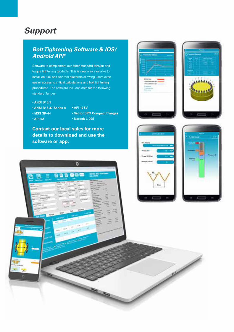
Bolt Tightening Software & IOS/Android APP
Software to complement our other standard tension and
torque tightening products. This is now also available to
install on IOS and Android platforms allowing users even
easier access to critical calculations and bolt tightening
procedures. The software includes data for the following
standard flanges:
• ANSI B16.5
• ANSI B16.47 Series A
• MSS SP-44
• API 6A
• API 17SV
• Vector SPO Compact Flanges
• Norsok L-005
Support
Contact our local sales for more details to download and use the software or app.

Notes

NOTES

NOTES

983
3 2
101
01
201
8:1
All
right
s re
serv
ed.
Info
rmat
ion
in th
is p
ublic
atio
n m
ay c
hang
e w
ithou
t not
ice.
Committed to sustainable productivityWe stand by our responsibilities towards our customers, towards the
environment and the people around us.
We make performance stand the test of time. This is what
we call - Sustainable Productivity.