Bollard Guide
8
Trelleborg Marine Systems | Takes the pressure off The Bollard Guide How we Make Certain Trelleborg Marine Systems | Takes the pressure off ASIA PACIFIC Trelleborg Marine Systems Australia Tel: +61 2 9285 0200 [email protected] Trelleborg Marine Systems Asia Tel: +65 6268 8005 [email protected] Trelleborg Marine Systems China Tel: +86 1351 532 29988 [email protected] PT Trelleborg Indonesia Tel: +62 21 797 6211 [email protected] Trelleborg Marine Systems Japan Tel: +81 3 3512 1981 [email protected] Trelleborg Marine Systems Docking & Mooring/Offshore Integrated Mooring, APAC & Main Office Tel: +61 3 9575 9999 [email protected] [email protected] INDIA, MIDDLE EAST & AFRICA Trelleborg Marine Systems Dubai Tel: +971 4 886 1825 [email protected] Trelleborg Marine Systems Docking & Mooring/Offshore Integrated Mooring, Middle East Tel: +971 4 886 1825 [email protected] [email protected] Trelleborg Marine Systems India Tel: +91 79 4001 3333 [email protected] Trelleborg Marine Systems South & East Africa Tel: +971 4 886 1825 [email protected] Trelleborg Marine Systems North & West Africa Tel: +33 1 41 39 22 20 [email protected] Trelleborg Marine Systems Docking & Mooring /Offshore Integrated Mooring, Middle East Tel: +971 4 886 1825 [email protected] [email protected] EUROPE & MEDITERRANEAN Trelleborg Marine Systems Benelux Tel: +31 180 43 40 40 [email protected] Trelleborg Marine Systems France & Spain Tel: +33 4 73 99 01 16 [email protected] Trelleborg Marine Systems Scandinavia Tel: +46 410 51730 [email protected] Trelleborg Marine Systems Germany Tel: +49 410 51067 [email protected] Trelleborg Marine Systems UK Tel: +44 1666 511770 [email protected] Trelleborg Marine Systems Eastern Europe & Russia Tel: +46 410 51088 [email protected] Trelleborg Marine Systems other parts of Europe Tel: +31 180 43 40 40 [email protected] Trelleborg Marine Systems Docking & Mooring /Offshore Integrated Mooring, Europe Tel: +44 7624 462776 [email protected] [email protected] SOUTH AMERICA Trelleborg Marine Systems Brazil Tel: +55 11 2802 9114 [email protected] Trelleborg Marine Systems Docking & Mooring /Offshore Integrated Mooring, South America Tel: +55 11 97211 9556 [email protected] [email protected] NORTH AMERICA & CANADA Trelleborg Marine Systems USA (Main Office) Tel: +1 540 723 2520 [email protected] Trelleborg Marine Systems USA (West Coast) Tel: +1 540 723 2520 [email protected] Trelleborg Marine Systems USA (East Coast) Tel: +1 540 723 2553 [email protected] Trelleborg Marine Systems USA (Gulf Coast and South East) Tel: +1 540 723 2553 [email protected] Trelleborg Marine Systems Melbourne Docking & Mooring Group North America Tel: +1 720 299 5506 [email protected] www.trelleborg.com/marine
description
Brosur Bollard untuk sandar kapal
Transcript of Bollard Guide

Trelleborg Marine Systems | Takes the pressure off
The Bollard GuideHow we Make Certain
Trelleborg Marine Systems | Takes the pressure off
ASIA PACIFIC
Trelleborg Marine Systems AustraliaTel: +61 2 9285 [email protected]
Trelleborg Marine Systems AsiaTel: +65 6268 [email protected]
Trelleborg Marine Systems ChinaTel: +86 1351 532 [email protected]
PT Trelleborg IndonesiaTel: +62 21 797 [email protected]
Trelleborg Marine Systems JapanTel: +81 3 3512 [email protected]
Trelleborg Marine SystemsDocking & Mooring/Offshore IntegratedMooring, APAC & Main OfficeTel: +61 3 9575 [email protected] [email protected]
INDIA, MIDDLE EAST & AFRICA
Trelleborg Marine Systems DubaiTel: +971 4 886 [email protected]
Trelleborg Marine SystemsDocking & Mooring/Offshore IntegratedMooring, Middle East Tel: +971 4 886 [email protected] [email protected]
Trelleborg Marine Systems IndiaTel: +91 79 4001 [email protected]
Trelleborg Marine SystemsSouth & East AfricaTel: +971 4 886 [email protected]
Trelleborg Marine Systems North& West AfricaTel: +33 1 41 39 22 [email protected]
Trelleborg Marine Systems Docking & Mooring /Offshore IntegratedMooring, Middle East Tel: +971 4 886 1825 [email protected]@trelleborg.com
EUROPE & MEDITERRANEAN
Trelleborg Marine Systems BeneluxTel: +31 180 43 40 [email protected]
Trelleborg Marine Systems France & SpainTel: +33 4 73 99 01 [email protected]
Trelleborg Marine Systems ScandinaviaTel: +46 410 [email protected]
Trelleborg Marine Systems GermanyTel: +49 410 [email protected]
Trelleborg Marine Systems UKTel: +44 1666 [email protected]
Trelleborg Marine Systems Eastern Europe & RussiaTel: +46 410 [email protected]
Trelleborg Marine Systems other parts of EuropeTel: +31 180 43 40 [email protected]
Trelleborg Marine Systems Docking & Mooring /Offshore IntegratedMooring, Europe Tel: +44 7624 462776 [email protected]@trelleborg.com
SOUTH AMERICA
Trelleborg Marine Systems BrazilTel: +55 11 2802 [email protected]
Trelleborg Marine Systems Docking & Mooring /Offshore IntegratedMooring, South America Tel: +55 11 97211 9556 [email protected]@trelleborg.com
NORTH AMERICA & CANADA
Trelleborg Marine Systems USA (Main Office) Tel: +1 540 723 2520 [email protected]
Trelleborg Marine Systems USA (West Coast) Tel: +1 540 723 2520 [email protected]
Trelleborg Marine Systems USA (East Coast) Tel: +1 540 723 2553 [email protected]
Trelleborg Marine Systems USA(Gulf Coast and South East)Tel: +1 540 723 2553 [email protected]
Trelleborg Marine Systems Melbourne Docking & Mooring Group North AmericaTel: +1 720 299 5506 [email protected]
www.trelleborg.com/marine
The
Bol
lard
Gui
deM
ake
Cer
tain Introduction
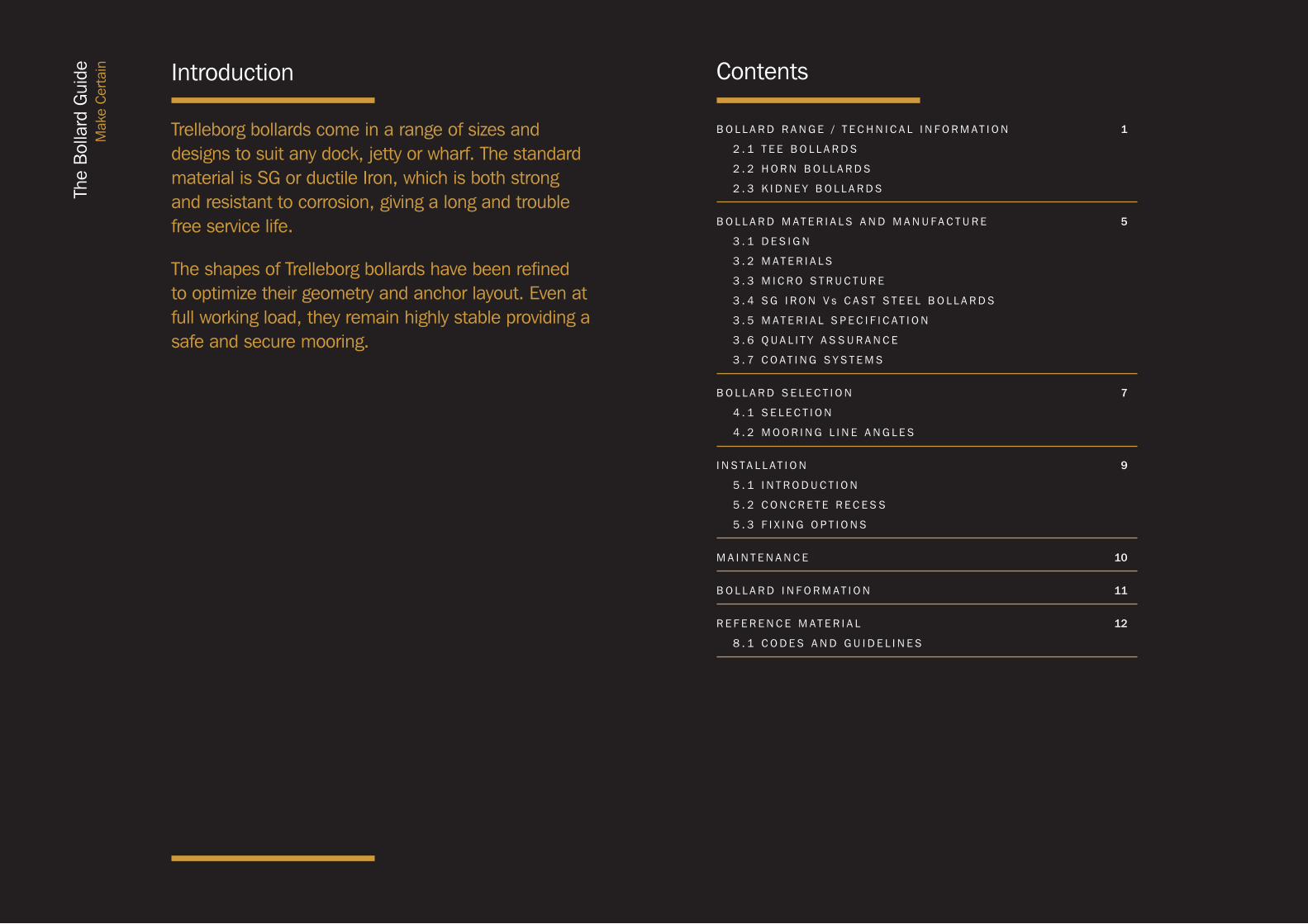
Trelleborg bollards come in a range of sizes and designs to suit any dock, jetty or wharf. The standard material is SG or ductile Iron, which is both strong and resistant to corrosion, giving a long and trouble free service life.
The shapes of Trelleborg bollards have been refined to optimize their geometry and anchor layout. Even at full working load, they remain highly stable providing a safe and secure mooring.
B O L L A R D R A N G E / T E C H N I C A L I N F O R M A T I O N 1
2 . 1 T E E B O L L A R D S
2 . 2 H O R N B O L L A R D S
2 . 3 K I D N E Y B O L L A R D S
B O L L A R D M A T E R I A L S A N D M A N U F A C T U R E 5
3 . 1 D E S I G N
3 . 2 M A T E R I A L S
3 . 3 M I C R O S T R U C T U R E
3 . 4 S G I R O N V s C A S T S T E E L B O L L A R D S
3 . 5 M A T E R I A L S P E C I F I C A T I O N
3 . 6 Q U A L I T Y A S S U R A N C E
3 . 7 C O A T I N G S Y S T E M S
B O L L A R D S E L E C T I O N 7
4 . 1 S E L E C T I O N
4 . 2 M O O R I N G L I N E A N G L E S
I N S T A L L A T I O N 9
5 . 1 I N T R O D U C T I O N
5 . 2 C O N C R E T E R E C E S S
5 . 3 F I X I N G O P T I O N S
M A I N T E N A N C E 10
B O L L A R D I N F O R M A T I O N 11
R E F E R E N C E M A T E R I A L 12
8 . 1 C O D E S A N D G U I D E L I N E S
Contents
Range / Technical Information1
Range / Technical Information2
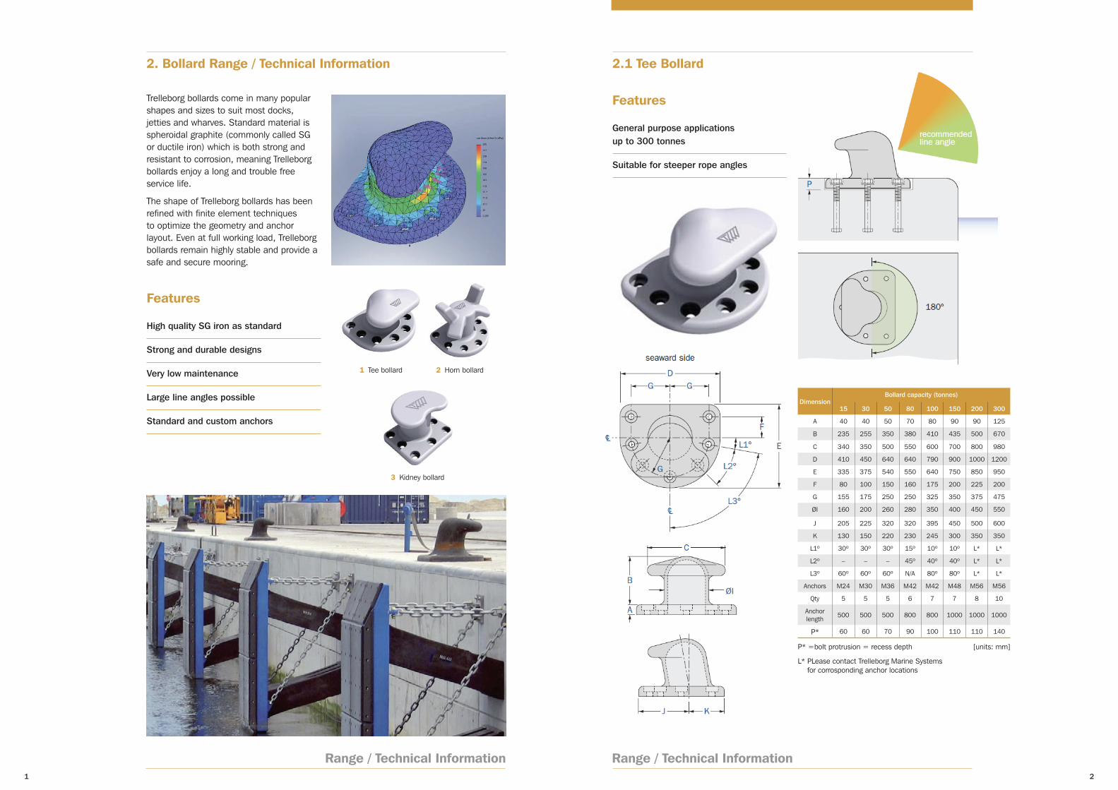
2. Bollard Range / Technical Information 2.1 Tee Bollard
Trelleborg bollards come in many popular shapes and sizes to suit most docks, jetties and wharves. Standard material is spheroidal graphite (commonly called SG or ductile iron) which is both strong and resistant to corrosion, meaning Trelleborg bollards enjoy a long and trouble free service life.
The shape of Trelleborg bollards has been refined with finite element techniques to optimize the geometry and anchor layout. Even at full working load, Trelleborg bollards remain highly stable and provide a safe and secure mooring.
1 Tee bollard 2 Horn bollard
3 Kidney bollard
Features
High quality SG iron as standard
Strong and durable designs
Very low maintenance
Large line angles possible
Standard and custom anchors
Features
General purpose applications up to 300 tonnes
Suitable for steeper rope angles
DimensionBollard capacity (tonnes)
15 30 50 80 100 150 200 300
A 40 40 50 70 80 90 90 125
B 235 255 350 380 410 435 500 670
C 340 350 500 550 600 700 800 980
D 410 450 640 640 790 900 1000 1200
E 335 375 540 550 640 750 850 950
F 80 100 150 160 175 200 225 200
G 155 175 250 250 325 350 375 475
ØI 160 200 260 280 350 400 450 550
J 205 225 320 320 395 450 500 600
K 130 150 220 230 245 300 350 350
L1º 30º 30º 30º 15º 10º 10º L* L*
L2º – – – 45º 40º 40º L* L*
L3º 60º 60º 60º N/A 80º 80º L* L*
Anchors M24 M30 M36 M42 M42 M48 M56 M56
Qty 5 5 5 6 7 7 8 10
Anchor length 500 500 500 800 800 1000 1000 1000
P* 60 60 70 90 100 110 110 140
P* =bolt protrusion = recess depth
L* PLease contact Trelleborg Marine Systems for corrosponding anchor locations
[units: mm]
43
Range / Technical Information
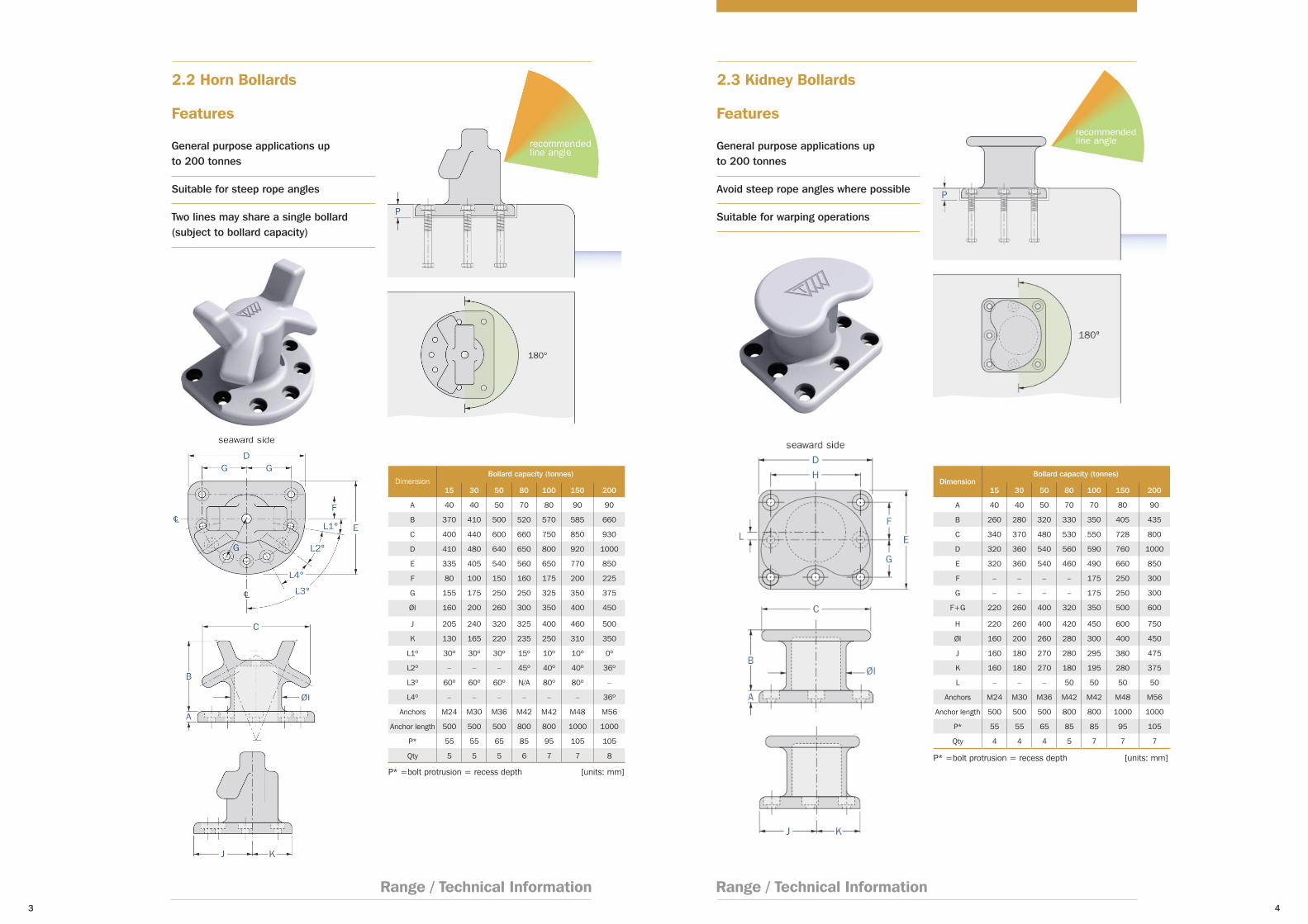
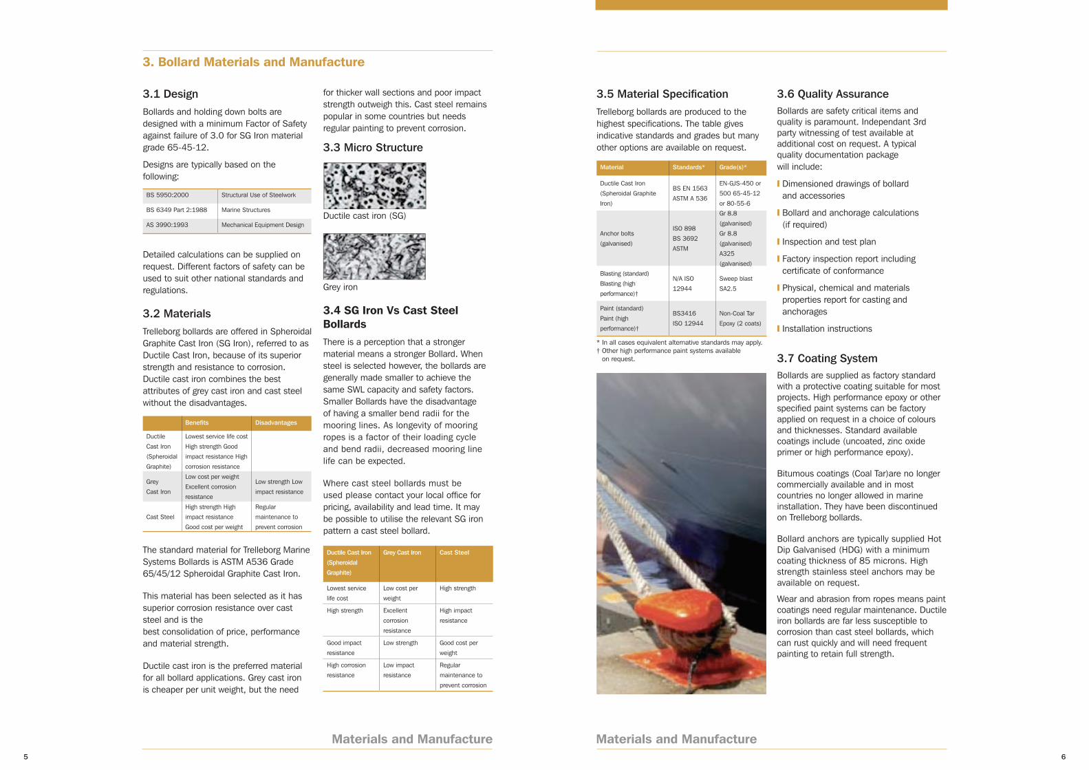
2.2 Horn Bollards 2.3 Kidney Bollards
Range / Technical Information
Features
General purpose applications up to 200 tonnes
Suitable for steep rope angles
Two lines may share a single bollard (subject to bollard capacity)
Features
General purpose applications up to 200 tonnes
Avoid steep rope angles where possible
Suitable for warping operations
DimensionBollard capacity (tonnes)
15 30 50 80 100 150 200
A 40 40 50 70 80 90 90
B 370 410 500 520 570 585 660
C 400 440 600 660 750 850 930
D 410 480 640 650 800 920 1000
E 335 405 540 560 650 770 850
F 80 100 150 160 175 200 225
G 155 175 250 250 325 350 375
ØI 160 200 260 300 350 400 450
J 205 240 320 325 400 460 500
K 130 165 220 235 250 310 350
L1º 30º 30º 30º 15º 10º 10º 0º
L2º – – – 45º 40º 40º 36º
L3º 60º 60º 60º N/A 80º 80º –
L4º – – – – – – 36º
Anchors M24 M30 M36 M42 M42 M48 M56
Anchor length 500 500 500 800 800 1000 1000
P* 55 55 65 85 95 105 105
Qty 5 5 5 6 7 7 8
P* =bolt protrusion = recess depth [units: mm]
DimensionBollard capacity (tonnes)
15 30 50 80 100 150 200
A 40 40 50 70 70 80 90
B 260 280 320 330 350 405 435
C 340 370 480 530 550 728 800
D 320 360 540 560 590 760 1000
E 320 360 540 460 490 660 850
F – – – – 175 250 300
G – – – – 175 250 300
F+G 220 260 400 320 350 500 600
H 220 260 400 420 450 600 750
ØI 160 200 260 280 300 400 450
J 160 180 270 280 295 380 475
K 160 180 270 180 195 280 375
L – – – 50 50 50 50
Anchors M24 M30 M36 M42 M42 M48 M56
Anchor length 500 500 500 800 800 1000 1000
P* 55 55 65 85 85 95 105
Qty 4 4 4 5 7 7 7
P* =bolt protrusion = recess depth [units: mm]
3. Bollard Materials and Manufacture
Materials and Manufacture5
Materials and Manufacture6
3.1 DesignBollards and holding down bolts are designed with a minimum Factor of Safety against failure of 3.0 for SG Iron material grade 65-45-12.
Designs are typically based on the following:
BS 5950:2000 Structural Use of Steelwork
BS 6349 Part 2:1988 Marine Structures
AS 3990:1993 Mechanical Equipment Design
Detailed calculations can be supplied on request. Different factors of safety can be used to suit other national standards and regulations.
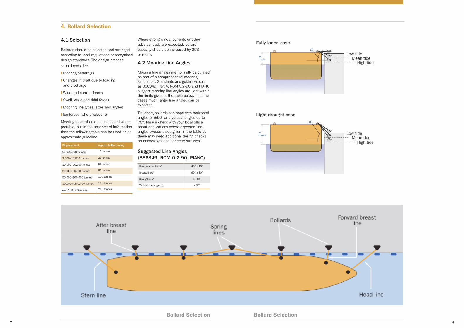
3.2 MaterialsTrelleborg bollards are offered in Spheroidal Graphite Cast Iron (SG Iron), referred to as Ductile Cast Iron, because of its superior strength and resistance to corrosion. Ductile cast iron combines the best attributes of grey cast iron and cast steel without the disadvantages.
Benefits Disadvantages
Ductile
Cast Iron
(Spheroidal
Graphite)
Lowest service life cost
High strength Good
impact resistance High
corrosion resistance
Grey
Cast Iron
Low cost per weight
Excellent corrosion
resistance
Low strength Low
impact resistance
Cast Steel
High strength High
impact resistance
Good cost per weight
Regular
maintenance to
prevent corrosion
The standard material for Trelleborg Marine Systems Bollards is ASTM A536 Grade 65/45/12 Spheroidal Graphite Cast Iron.
This material has been selected as it has superior corrosion resistance over cast steel and is the best consolidation of price, performance and material strength.
Ductile cast iron is the preferred material for all bollard applications. Grey cast iron is cheaper per unit weight, but the need
3.5 Material SpecificationTrelleborg bollards are produced to the highest specifications. The table gives indicative standards and grades but many other options are available on request.
Material Standards* Grade(s)*
Ductile Cast Iron
(Spheroidal Graphite
Iron)
BS EN 1563
ASTM A 536
EN-GJS-450 or
500 65-45-12
or 80-55-6
Anchor bolts
(galvanised)
ISO 898
BS 3692
ASTM
Gr 8.8
(galvanised)
Gr 8.8
(galvanised)
A325
(galvanised)
Blasting (standard)
Blasting (high
performance)†
N/A ISO
12944
Sweep blast
SA2.5
Paint (standard)
Paint (high
performance)†
BS3416
ISO 12944
Non-Coal Tar
Epoxy (2 coats)
3.6 Quality AssuranceBollards are safety critical items and quality is paramount. Independant 3rd party witnessing of test available at additional cost on request. A typical quality documentation package will include:
❙ Dimensioned drawings of bollard and accessories
❙ Bollard and anchorage calculations (if required)
❙ Inspection and test plan
❙ Factory inspection report including certificate of conformance
❙ Physical, chemical and materials properties report for casting and anchorages
❙ Installation instructions
3.7 Coating SystemBollards are supplied as factory standard with a protective coating suitable for most projects. High performance epoxy or other specified paint systems can be factory applied on request in a choice of colours and thicknesses. Standard available coatings include (uncoated, zinc oxide primer or high performance epoxy).
Bitumous coatings (Coal Tar)are no longer commercially available and in most countries no longer allowed in marine installation. They have been discontinued on Trelleborg bollards.
Bollard anchors are typically supplied Hot Dip Galvanised (HDG) with a minimum coating thickness of 85 microns. High strength stainless steel anchors may be available on request.
Wear and abrasion from ropes means paint coatings need regular maintenance. Ductile iron bollards are far less susceptible to corrosion than cast steel bollards, which can rust quickly and will need frequent painting to retain full strength.
for thicker wall sections and poor impact strength outweigh this. Cast steel remains popular in some countries but needs regular painting to prevent corrosion.
3.3 Micro Structure
Ductile cast iron (SG)
Grey iron
3.4 SG Iron Vs Cast Steel BollardsThere is a perception that a stronger material means a stronger Bollard. When steel is selected however, the bollards are generally made smaller to achieve the same SWL capacity and safety factors. Smaller Bollards have the disadvantage of having a smaller bend radii for the mooring lines. As longevity of mooring ropes is a factor of their loading cycle and bend radii, decreased mooring line life can be expected.
Where cast steel bollards must be used please contact your local office for pricing, availability and lead time. It may be possible to utilise the relevant SG iron pattern a cast steel bollard.
Ductile Cast Iron
(Spheroidal
Graphite)
Grey Cast Iron Cast Steel
Lowest service
life cost
Low cost per
weight
High strength
High strength Excellent
corrosion
resistance
High impact
resistance
Good impact
resistance
Low strength Good cost per
weight
High corrosion
resistance
Low impact
resistance
Regular
maintenance to
prevent corrosion
* In all cases equivalent alternative standards may apply. † Other high performance paint systems available
on request.
87
Bollard SelectionBollard Selection
4. Bollard Selection
4.1 Selection
Bollards should be selected and arranged according to local regulations or recognised design standards. The design process should consider:
❙ Mooring pattern(s)
❙ Changes in draft due to loading and discharge
❙ Wind and current forces
❙ Swell, wave and tidal forces
❙ Mooring line types, sizes and angles
❙ Ice forces (where relevant)
Mooring loads should be calculated where possible, but in the absence of information then the following table can be used as an approximate guideline.
Displacement Approx. bollard rating
Up to 2,000 tonnes 10 tonnes
2,000–10,000 tonnes 30 tonnes
10,000–20,000 tonnes 60 tonnes
20,000–50,000 tonnes 80 tonnes
50,000–100,000 tonnes 100 tonnes
100,000–200,000 tonnes 150 tonnes
over 200,000 tonnes 200 tonnes
Where strong winds, currents or other adverse loads are expected, bollard capacity should be increased by 25% or more.
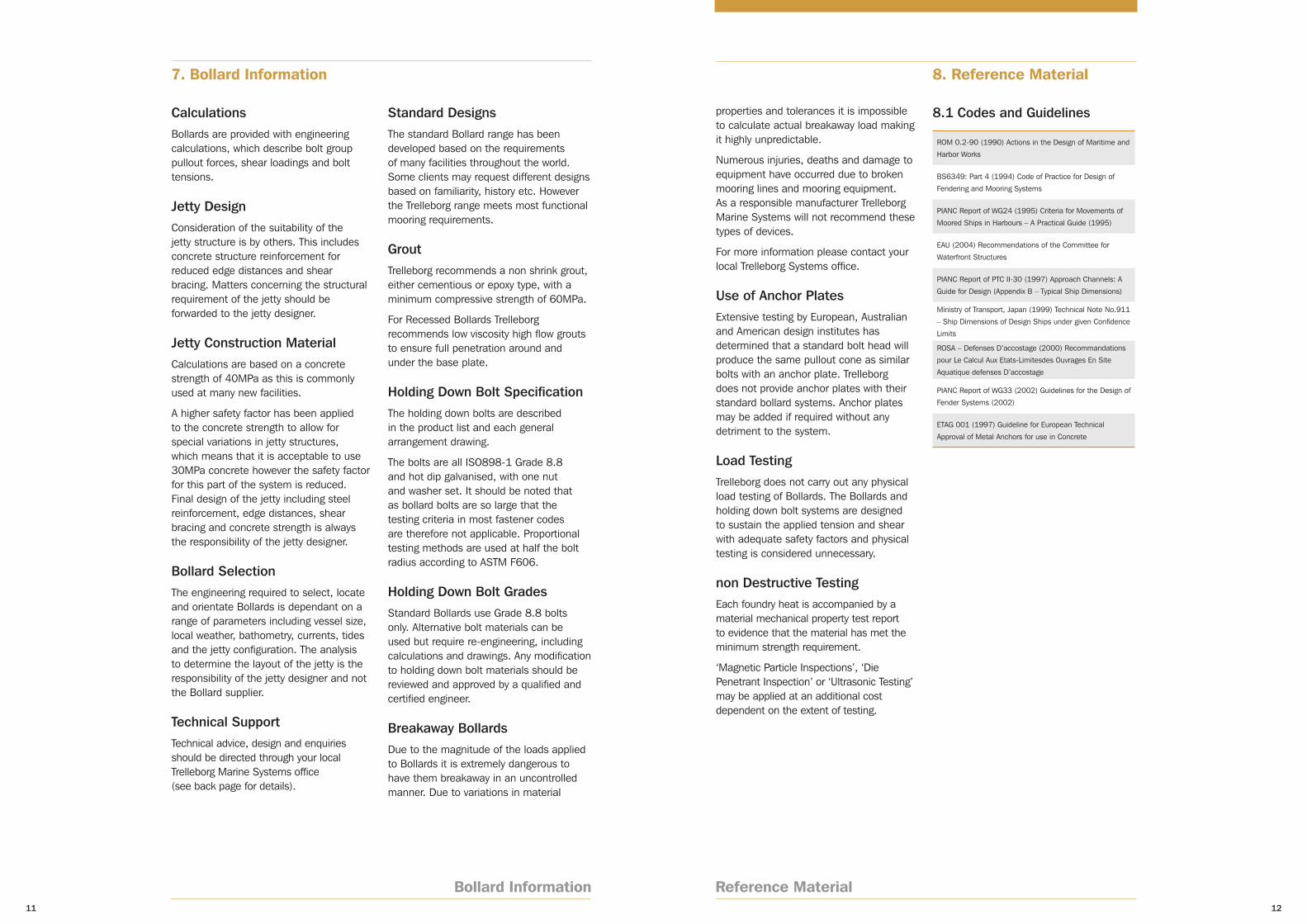
4.2 Mooring Line Angles
Mooring line angles are normally calculated as part of a comprehensive mooring simulation. Standards and guidelines such as BS6349: Part 4, ROM 0.2-90 and PIANC suggest mooring line angles are kept within the limits given in the table below. In some cases much larger line angles can be expected.
Trelleborg bollards can cope with horizontal angles of ±90° and vertical angles up to 75°. Please check with your local office about applications where expected line angles exceed those given in the table as these may need additional design checks on anchorages and concrete stresses.
Suggested Line Angles (BS6349, ROM 0.2-90, PIANC)
Head & stern lines* 45° ±15°
Breast lines* 90° ±30°
Spring lines* 5–10°
Vertical line angle (x) <30°

5. Installation 6. Maintenance
Installation9
Maintenance10
5.1 Introduction
Bollards must be installed correctly for a long and trouble-free service life. Anchors should be accurately set out with the supplied template. Bollards can be recessed (as shown) or alternatively surface mounted. Once the grout has reached full strength, anchors can be fully tightened. Mastic is often applied around exposed threads to ease future removal.
5.2 Concrete Recess
*refer to dimensions tables
Recessing the bollard is generally recognised as superior to surface mounting. Recessing the base prevents the bollard from working loose on its bolts or cracking the grout bed – especially relevant for high use locations.
5.1 Introduction
Like all equipment in the marine environment, regular inspection and maintenance is critical to achieving maximum life expectancy.
Trelleborg recommend a regular scheduled inspection of equipment such as bollards as part of any berth. Key items that need to be focussed on during the inspection and maintenance include:
1. Paint
Bollards are supplied as factory standard with a protective coating suitable for most projects. High performance epoxy or other specified paint systems are usually applied at the factory on request in a choice of colours and thicknesses.
Wear and abrasion from ropes means paint coatings need regular maintenance. Like all epoxy coating systems, maintenance is integral to increasing life expectancy. Trelleborg recommend regular inspection of the bollards
Repair and upkeep of the coating system is dependant upon the coating system selected. Trelleborg try to utilise commercially available coating systems to ensure local products can be sourced and system repair procedures are in line with the coating system manufacturers guidelines.
5.3 Fixing Options
2. Grout
Installation and grout filling requires extra care to avoid damage to factory applied coatings. Similarly regular inspection and possible repair of grout under and around the bollard is critical to the ongoing integrity of bollard performance. Should grout be cracked or damaged it is recommended that it be replaced.
3. Hold Down Bolts
Hold down bolts are critical to bollard performance. Ensuring correct torque settings will ensure bollards and hold down bolts achieve optimum performance. These are critical to be checked during installation.
Visual checks on hold down bolts should be undertaken during regular maintenance to ensure no loosening of bolts has occurred.
4. Bollard Materials
Ductile iron bollards are far less susceptible to corrosion than cast steel bollards, which can rust quickly and will need frequent painting to retain full strength. Regular inspection of the bollard materials is recommended.
Trelleborg are happy to assist in providing inspection services on berthing and mooring equipment.
Fuse bolts available on special request.
Bollard Information11
Reference Material12
7. Bollard Information 8. Reference Material
CalculationsBollards are provided with engineering calculations, which describe bolt group pullout forces, shear loadings and bolt tensions.
Jetty DesignConsideration of the suitability of the jetty structure is by others. This includes concrete structure reinforcement for reduced edge distances and shear bracing. Matters concerning the structural requirement of the jetty should be forwarded to the jetty designer.
Jetty Construction MaterialCalculations are based on a concrete strength of 40MPa as this is commonly used at many new facilities.
A higher safety factor has been applied to the concrete strength to allow for special variations in jetty structures, which means that it is acceptable to use 30MPa concrete however the safety factor for this part of the system is reduced. Final design of the jetty including steel reinforcement, edge distances, shear bracing and concrete strength is always the responsibility of the jetty designer.
Bollard SelectionThe engineering required to select, locate and orientate Bollards is dependant on a range of parameters including vessel size, local weather, bathometry, currents, tides and the jetty configuration. The analysis to determine the layout of the jetty is the responsibility of the jetty designer and not the Bollard supplier.
Technical SupportTechnical advice, design and enquiries should be directed through your local Trelleborg Marine Systems office (see back page for details).
8.1 Codes and Guidelines
ROM 0.2-90 (1990) Actions in the Design of Maritime and
Harbor Works
BS6349: Part 4 (1994) Code of Practice for Design of
Fendering and Mooring Systems
PIANC Report of WG24 (1995) Criteria for Movements of
Moored Ships in Harbours – A Practical Guide (1995)
EAU (2004) Recommendations of the Committee for
Waterfront Structures
PIANC Report of PTC II-30 (1997) Approach Channels: A
Guide for Design (Appendix B – Typical Ship Dimensions)
Ministry of Transport, Japan (1999) Technical Note No.911
– Ship Dimensions of Design Ships under given Confidence
Limits
ROSA – Defenses D’accostage (2000) Recommandations
pour Le Calcul Aux Etats-Limitesdes Ouvrages En Site
Aquatique defenses D’accostage
PIANC Report of WG33 (2002) Guidelines for the Design of
Fender Systems (2002)
ETAG 001 (1997) Guideline for European Technical
Approval of Metal Anchors for use in Concrete
Standard DesignsThe standard Bollard range has been developed based on the requirements of many facilities throughout the world. Some clients may request different designs based on familiarity, history etc. However the Trelleborg range meets most functional mooring requirements.
GroutTrelleborg recommends a non shrink grout, either cementious or epoxy type, with a minimum compressive strength of 60MPa.
For Recessed Bollards Trelleborg recommends low viscosity high flow grouts to ensure full penetration around and under the base plate.
Holding Down Bolt SpecificationThe holding down bolts are described in the product list and each general arrangement drawing.
The bolts are all ISO898-1 Grade 8.8 and hot dip galvanised, with one nut and washer set. It should be noted that as bollard bolts are so large that the testing criteria in most fastener codes are therefore not applicable. Proportional testing methods are used at half the bolt radius according to ASTM F606.
Holding Down Bolt GradesStandard Bollards use Grade 8.8 bolts only. Alternative bolt materials can be used but require re-engineering, including calculations and drawings. Any modification to holding down bolt materials should be reviewed and approved by a qualified and certified engineer.
Breakaway BollardsDue to the magnitude of the loads applied to Bollards it is extremely dangerous to have them breakaway in an uncontrolled manner. Due to variations in material
properties and tolerances it is impossible to calculate actual breakaway load making it highly unpredictable.
Numerous injuries, deaths and damage to equipment have occurred due to broken mooring lines and mooring equipment. As a responsible manufacturer Trelleborg Marine Systems will not recommend these types of devices.
For more information please contact your local Trelleborg Systems office.
Use of Anchor PlatesExtensive testing by European, Australian and American design institutes has determined that a standard bolt head will produce the same pullout cone as similar bolts with an anchor plate. Trelleborg does not provide anchor plates with their standard bollard systems. Anchor plates may be added if required without any detriment to the system.
Load TestingTrelleborg does not carry out any physical load testing of Bollards. The Bollards and holding down bolt systems are designed to sustain the applied tension and shear with adequate safety factors and physical testing is considered unnecessary.
non Destructive TestingEach foundry heat is accompanied by a material mechanical property test report to evidence that the material has met the minimum strength requirement.
‘Magnetic Particle Inspections’, ‘Die Penetrant Inspection’ or ‘Ultrasonic Testing’ may be applied at an additional cost dependent on the extent of testing.