![Application of Boiling Heat Transfer to High-Heat-Flux · PDF file127 Suzuki et al.: Application of Boiling Heat Transfer (1/7) [Tutorial Paper] Application of Boiling Heat Transfer](https://static.fdocuments.net/doc/165x107/5ab004da7f8b9aa8438e12d1/application-of-boiling-heat-transfer-to-high-heat-flux-suzuki-et-al-application.jpg)
Boiling heat transfer in electric vehicles - Pure - Aanmelden · Boiling heat transfer in electric...
66
Boiling heat transfer in electric vehicles van Gils, R.W.; Speetjens, M.F.M.; Nijmeijer, H. Published: 01/01/2011 Document Version Publisher’s PDF, also known as Version of Record (includes final page, issue and volume numbers) Please check the document version of this publication: • A submitted manuscript is the author's version of the article upon submission and before peer-review. There can be important differences between the submitted version and the official published version of record. People interested in the research are advised to contact the author for the final version of the publication, or visit the DOI to the publisher's website. • The final author version and the galley proof are versions of the publication after peer review. • The final published version features the final layout of the paper including the volume, issue and page numbers. Link to publication Citation for published version (APA): Gils, van, R. W., Speetjens, M. F. M., & Nijmeijer, H. (2011). Boiling heat transfer in electric vehicles. (D&C; Vol. 2011.52). Eindhoven: Eindhoven University of Technology. General rights Copyright and moral rights for the publications made accessible in the public portal are retained by the authors and/or other copyright owners and it is a condition of accessing publications that users recognise and abide by the legal requirements associated with these rights. • Users may download and print one copy of any publication from the public portal for the purpose of private study or research. • You may not further distribute the material or use it for any profit-making activity or commercial gain • You may freely distribute the URL identifying the publication in the public portal ? Take down policy If you believe that this document breaches copyright please contact us providing details, and we will remove access to the work immediately and investigate your claim. Download date: 23. Jun. 2018
Transcript of Boiling heat transfer in electric vehicles - Pure - Aanmelden · Boiling heat transfer in electric...
Boiling heat transfer in electric vehicles
van Gils, R.W.; Speetjens, M.F.M.; Nijmeijer, H.
Published: 01/01/2011
Document VersionPublisher’s PDF, also known as Version of Record (includes final page, issue and volume numbers)
Please check the document version of this publication:
• A submitted manuscript is the author's version of the article upon submission and before peer-review. There can be important differencesbetween the submitted version and the official published version of record. People interested in the research are advised to contact theauthor for the final version of the publication, or visit the DOI to the publisher's website.• The final author version and the galley proof are versions of the publication after peer review.• The final published version features the final layout of the paper including the volume, issue and page numbers.
Link to publication
Citation for published version (APA):Gils, van, R. W., Speetjens, M. F. M., & Nijmeijer, H. (2011). Boiling heat transfer in electric vehicles. (D&C; Vol.2011.52). Eindhoven: Eindhoven University of Technology.
General rightsCopyright and moral rights for the publications made accessible in the public portal are retained by the authors and/or other copyright ownersand it is a condition of accessing publications that users recognise and abide by the legal requirements associated with these rights.
• Users may download and print one copy of any publication from the public portal for the purpose of private study or research. • You may not further distribute the material or use it for any profit-making activity or commercial gain • You may freely distribute the URL identifying the publication in the public portal ?
Take down policyIf you believe that this document breaches copyright please contact us providing details, and we will remove access to the work immediatelyand investigate your claim.
Download date: 23. Jun. 2018
Boiling Heat Transfer in Electric
Vehicles
R.W. van Gils
DC 2011.52
Literature survey
Co-supervisor: M.F.M. Speetjens
Supervisor: H. Nijmeijer
Eindhoven University of TechnologyDepartment of Mechanical EngineeringDynamics and Control Group
Eindhoven, January 9, 2012

Contents
List of abbreviations V
1 Introduction 1
1.1 Background . . . . . . . . . . . . . . . . . . . . . . . . . . . . . . . . . . . . . . 1
1.2 EV history . . . . . . . . . . . . . . . . . . . . . . . . . . . . . . . . . . . . . . 1
1.3 Motivation . . . . . . . . . . . . . . . . . . . . . . . . . . . . . . . . . . . . . . . 2
1.4 Goal . . . . . . . . . . . . . . . . . . . . . . . . . . . . . . . . . . . . . . . . . . 3
1.5 Outline . . . . . . . . . . . . . . . . . . . . . . . . . . . . . . . . . . . . . . . . 4
2 Current EV’s 5
2.1 Battery electric vehicles . . . . . . . . . . . . . . . . . . . . . . . . . . . . . . . 5
2.1.1 Tesla Roadster . . . . . . . . . . . . . . . . . . . . . . . . . . . . . . . . 6
2.1.2 Nissan Leaf . . . . . . . . . . . . . . . . . . . . . . . . . . . . . . . . . . 6
2.1.3 GM EV1 . . . . . . . . . . . . . . . . . . . . . . . . . . . . . . . . . . . 7
2.1.4 Ford Think City . . . . . . . . . . . . . . . . . . . . . . . . . . . . . . . 7
2.1.5 Other BEVs . . . . . . . . . . . . . . . . . . . . . . . . . . . . . . . . . . 8
2.2 Hybrid electric vehicles . . . . . . . . . . . . . . . . . . . . . . . . . . . . . . . . 8
2.2.1 Chevrolet Volt . . . . . . . . . . . . . . . . . . . . . . . . . . . . . . . . 8
2.2.2 Toyota Prius . . . . . . . . . . . . . . . . . . . . . . . . . . . . . . . . . 9
2.2.3 Honda Insight . . . . . . . . . . . . . . . . . . . . . . . . . . . . . . . . . 9
2.3 Cooling schemes analysed . . . . . . . . . . . . . . . . . . . . . . . . . . . . . . 10
3 Energy management in EVs 11
3.1 Energy requirements for driving . . . . . . . . . . . . . . . . . . . . . . . . . . . 11
3.2 Auxiliary energy requirements . . . . . . . . . . . . . . . . . . . . . . . . . . . . 11
3.3 Conclusion . . . . . . . . . . . . . . . . . . . . . . . . . . . . . . . . . . . . . . . 14
4 Thermal Issues in EVs 15
4.1 Thermal management of the ESS . . . . . . . . . . . . . . . . . . . . . . . . . . 15
4.2 Overheating of insulated gate bipolar transistors . . . . . . . . . . . . . . . . . 16
5 Motivation Pool-boiling project 19
5.1 Pool-boiling . . . . . . . . . . . . . . . . . . . . . . . . . . . . . . . . . . . . . . 19
5.2 Why pool-boiling . . . . . . . . . . . . . . . . . . . . . . . . . . . . . . . . . . . 20
5.3 Objective and strategy . . . . . . . . . . . . . . . . . . . . . . . . . . . . . . . . 21
5.4 Case studies . . . . . . . . . . . . . . . . . . . . . . . . . . . . . . . . . . . . . . 22
5.4.1 Control strategy . . . . . . . . . . . . . . . . . . . . . . . . . . . . . . . 25
5.4.2 Closed-loop Simulations . . . . . . . . . . . . . . . . . . . . . . . . . . . 28
5.4.3 Conclusion . . . . . . . . . . . . . . . . . . . . . . . . . . . . . . . . . . 34
6 Conclusions 37
III

IV Contents
Acknowledgements 39
Bibliography 41
A Paper EEVC 47
List of abbreviations
Acronym Description
A/C Air ConditioningAC Alternating CurrentAER All Electric RangeBEV Battery Electric VehicleBJT Bipolar Junction TransistorCHF Critical Heat FluxCID Current Interrupt DeviceDC Direct CurrentESS Energy Storage SystemEV Electric VehicleFCEV Fuel Cell Electric VehicleGM General MotorsHEV Hybrid Electric VehicleHVAC Heating Ventilation Air ConditioningHTAS High Tech Automotive SystemsIBM International Business Machines CorporationICE Internal Combustion EngineIGBT Insulated Gate Bipolar TransistorIMA Integrated Motor AssistkWh kiloWatt hourLi-ion Lithium ionMOSFET Metal Oxide Semiconductor Field Effect TransistorNiMH Nickel Metal HydridePCM Phase Change MaterialPHEV Plug-in Hybrid Electric VehiclePM Permanent MagnetPTC Positive Temperature CoefficientREI Range Extender InnovationsTES Thermal Energy StorageTU/e Eindhoven University of TechnologyUDDS Urban Dynamometer Driving ScheduleZEV Zero Emission Vehicle
V

VI List of abbreviations
1 Introduction
1.1 Background
Environmental as well as economical issues provide a compelling motive to develop clean,efficient, and sustainable vehicles for urban transportation. Automobiles constitute an integralpart of our everyday life, yet the exhaust emissions of conventional internal combustion engine(ICE) vehicles are to blame for the major source of urban pollution that causes the greenhouseeffect leading to global warming. Moreover, the dependence on oil as the sole source of energyfor passenger vehicles has economical and political implications, and the crisis will inevitablybecome acute as the oil reserve of the world diminishes.
An alternative to the polluting ICE vehicles are electric vehicles (EV). Electric vehiclesdo not necessarily reduce the overall amount of energy used, however, this energy is no longergenerated onboard, as in ICE vehicles. This energy is generated by power stations, whichcan use a wide variety of fuels and where the exhaust emissions can be handled responsibly.The wide range of sources for generating this electricity include, fossil fuels, nuclear power,and renewable sources such as tidal power, solar power, and wind power. This energy isthen transmitted to the vehicle through use of overhead lines, wireless energy transfer suchas inductive charging, or a direct connection through an electrical cable. The electricity maythen be stored onboard the vehicle using a battery, flywheel, or supercapacitors. Electricvehicles enabled by high-efficiency electric motors and controllers and powered by alternativeenergy sources thus provide the means for a clean, efficient, and environmentally friendlyurban transportation system. Since, electric vehicles have little or no emission, they havethe potential to curb the pollution problem in an efficient way. Moreover, EVs are the onlyvehicles that have the potential to become zero-emission vehicles (ZEV) [26].
An electric vehicle (EV) is a vehicle which uses one or more electric motors for propulsion.Depending on the type of vehicle, motion may be provided by wheels or propellers driven byrotary motors, or in the case of tracked vehicles, by linear motors. Among the most widelyused electric vehicles are electric bicycles and electric trains, see [36]. However, for the abovedescribed pollution problem to be decreased, the ICE cars should be replaced by electric cars.Currently, one of the main reasons for the prolongation of ICE vehicles is the range of today’selectric vehicles on one battery charge. The range of these vehicles is mainly determinedby the performance and cycle life of the vehicle’s battery pack. The latter can be improvedby thermally managing the battery pack [21]. The use of auxiliary systems such as cabinheating and air conditioning (A/C) influence the range negatively as well. This influence canbe decreased by recovering waste heat for the benefit of cabin heating and implementing moreefficient heat transfer methods.
1.2 EV history
Electric cars first came into existence in the mid-19th century, when electricity was among thepreferred methods for automobile propulsion, providing a level of comfort and ease of operationthat could not be achieved by the gasoline cars of that time. The invention of the starter motor
1
2 1 Introduction
for the ICE vehicles, their mass production, and the inconvenience of battery charging, hasresulted in the complete replacement of the electric drive by the internal combustion engine(ICE) as a propulsion method for automobiles in the early 1900s. However, electric power hasremained commonplace in other vehicle types, such as trains and smaller vehicles of all types.
During the last few decades, increased concern over the environmental impact of thepetroleum-based transportation infrastructure, along with the spectre of peak oil, has led torenewed interest in an electric transportation infrastructure. Vehicles making use of enginesworking on the principle of combustion can usually only derive their energy from a single or afew sources, usually non-renewable fossil fuels. Moreover, a key advantage of electric vehiclesis regenerative braking, which allows EVs to recover energy normally lost during braking aselectricity to be restored to the on-board energy storage system (ESS).
In 2003 the first mass produced hybrid gasoline-electric vehicle, the Toyota Prius, wasintroduced worldwide, and major auto companies have plans to introduce (plug-in) hybridand true battery electric vehicles (BEV) in showrooms in 2010 and 2011.
On today’s automobile market, several production BEVs and HEVs are available for saleor lease to the general public, such as Tesla Roadster, Ford Think City and Mitsubishi iMiEV(BEV) and Toyota Prius, Chevrolet Volt and Honda Insight (HEV). Furthermore, multipleEVs are ready to be launched in 2011 or 2012, e.g. Peugeot 106 Electric, Toyota RAV4 andNissan Leaf (BEV) and Mercedes S400 BlueHybrid (HEV). There are also many prototypeand experimental EVs being developed by the major automotive manufacturers. Most ofthese vehicles use Alternating Current (AC) induction motors or Permanent Magnet (PM)synchronous motors. Furthermore, almost all of these vehicles use battery technology otherthan the lead-acid battery pack, which ruled the battery scene for almost a century [26,32,36].
1.3 Motivation
In the 1990s the manufacturers of EVs realised that the further development of ZEV technolo-gies was hindered by unsuitable battery technologies. Technical developments have increasedthe specific energy of batteries, though. Commercially available batteries such as nickel cad-mium or nickel-metal-hydride can carry at best double the energy of lead acid batteries, thehigh temperature Sodium-nickel-chloride or Zebra battery nearly three times. However, inpractice, the rechargeable battery with the highest specific energy available is the lithiumpolymer battery which has a specific energy about three times that of lead-acid. However,next to the fact the this type of battery is expensive, it is investigated that air cooling is insuf-ficient for heat dissipation from large-scale batteries due to the lower thermal conductivity ofthe polymer [11]. Therefore, the lithium-ion battery is seen as the current best choice for EVbatteries [23, 32, 46, 61]. The advantages of this technology compared to conventional NiMHbatteries used to date include [23]:
• Greater performance and energy density.
• Highly compact physical dimensions.
• High charge and discharge efficiency.
• High cyclability.
1.4 Goal 3
Although BEVs for everyday use do not require an active thermal management scheme foroptimal performance of their battery, such schemes can improve lifespan of the battery signif-icantly. Furthermore, recovering the small amount of waste heat can be used for heating thecabin which indirectly leads to extended range per charge, as less electricity is required forheating in that case. As a reaction on the shortcomings of the battery technologies, in par-ticular the Japanese auto industries started to develop hybrid electric vehicles (HEV). Thesehybrid vehicles use an electric motor and an internal combustion engine and thus do not solvethe pollution problem, although it does mitigate it.
The shortcomings in lifespan of today’s battery technology can be decreased by a good ther-mal management of EV batteries during charge and discharge procedures. As reaction timesdecrease and reaction resistances, power and capacity increase with temperature, unwantedreactions speed up and degrade the life of the battery faster at higher temperatures [46]. Thisholds for all kinds of battery technologies; lithium-ion (Li-ion), Nickel-metal-hydride (NiMH),lithium polymer batteries and lead-acid batteries, [1, 6, 32, 49, 61]. An overview of propertiesof these specific batteries can be found in [21, 26].
Thermal issues are of more concern in HEV pack’s relative to battery electric vehicle(BEV) pack’s, because of higher power and a more aggressive charge/discharge profile [48].On the other hand the range of BEV is a crucial variable for its success, meaning the thermalmanagement system may not use too much energy. Furthermore, the dissipated heat mustbe released at desired locations in order to waste as less energy as possible. The additionalthermal management requirements associated with electric drive systems are also a recognizedchallenge in terms of costs related to the thermal management hardware, not only in terms ofdollars but also in weight and size that impact the overall vehicle mass, cargo space, componentpackaging space and total component count [6].
1.4 Goal
As is discussed in the above, the critical component for further development of EVs is consid-ered to be the energy storage system (ESS), which is a battery in most EVs [46]. Therefore,in this study cooling of electrical components to recover waste heat and batteries to increaselifespan in EVs is studied. The goal of this report is to gain insight in the thermal issues asso-ciated with performance of EVs in terms of range per charge and lifespan. Moreover, some ofthe cooling methods in today’s EVs are investigated in order to place new methods in the rightperspective regarding, usefulness, to what extend such cooling systems are required and towhat extend the technology is really innovative. In this context also the cooling requirementsof the electric motors that accelerate an EV from zero to 100 km/h in less than ten secondsare investigated.
Research will be performed on a pool-boiling model, first introduced in [16, 17, 52, 53], inorder to obtain a good insight in pool-boiling phenomena. A pool-boiling system may act asphysical model for heat dissipation designs based on boiling heat transfer. Such systems canbe controlled by varying the sytem pressure p, which influences the critical heat flux (CHF),CHF ∝ p, see Chapter 5. The model for pool-boiling system used here is normalised for thisCHF and decreasing (increasing) the pressure thus is modelled as increasing (decreasing) thenominal heat supply QH , QH ∝ p−1. In the model stabilisation thus is to be acquired viacontrol of a variable heat flux. This will be further discussed in Chapter 5.
The key advantages of a pool-boiling cooling scheme in EVs are (i) the reduction of weight
4 1 Introduction
compared to the weight of a single-phase cooling loop, (ii) temperature uniformity of thebattery in favour of battery lifespan and (iii) waste heat recovery for cabin heating. As theenergy density per unit mass of the coolant is much larger than that of a single-phase coolingloop, the mass of the required coolant in the cooling design is much lower. Since boiling heattransfer occurs at a constant temperature irrespective of the heat flux, thermal managementby boiling heat transfer allows for optimal temperature homogenisation of the battery. Asboiling heat transfer allows for quick and intensive cooling, the removed heat can be releasedeasily by condensation to any desired surface, for example for cabin heating.
1.5 Outline
This study is organised as follows. First in the next chapter, Chapter 2, the battery systemsand cooling methods used in today’s BEVs and HEVs are discussed and conclusion regardingthese cooling schemes are drawn. In the subsequent chapter, Chapter 3, the power require-ments of some EVs are discussed. Also the range and influence of auxiliary power requirementson range are discussed in this chapter. Then in Chapter 4 the thermal issues in EVs are dis-cussed and in Chapter 5 a motivation for the research of pool-boiling phenomena is given.Finally, in the last chapter some conclusions are drawn.
2 Current EV’s
As is mentioned in the introduction, a number of commercial, prototype, and experimentalelectrical vehicle models are available on today’s automotive market. Almost all major auto-motive manufacturers produce some kind of EV or plan to do so in the near future. There areeffectively six basic types of electric vehicles, [36];
1. The traditional battery electric vehicle (BEV).
2. The hybrid electric vehicle (HEV).
3. Vehicles which use replaceable fuel as the source of energy, the fuel cell electric vehicles(FCEV).
4. Vehicles supplied by power lines, e.g. trains.
5. Solar electric vehicles.
6. Vehicles that store energy in an alternative way, such as flywheels and super capacitors[21], these are almost always hybrids, using some other source of power as well.
In this Chapter only the first two types of EVs are discussed. In particular the cooling ofthe electrical components and batteries in BEVs and HEVs is discussed in the following twosections.
2.1 Battery electric vehicles
The type of electric vehicle that usually springs to mind when people think of electric vehiclesis the battery electric vehicle. In a BEV the energy is supplied by a battery only and itspropulsion mechanism solely supplied by electrical energy, making it a zero-emission vehicle(ZEV). The range per charge of these vehicles thus is solely determined by the size of thebattery. Main drawback of current BEVs is the range per charge, todays battery technologycan not meet the needs of todays vehicle users. Another drawback is the degredation of thebatteries, after several hundreds of cycles the capacity of the battery typically decreases to80% or less of its original capacity. If the batteries are used at elevated temperatures, thisdegradation even increases, see Chapter 4. A good thermal management scheme can improvelifespan and to less extend performance of EV batteries. On today’s automobile marketseveral BEVs are available, most of them use Li-ion technologies, but there are exceptions.The following BEVs are discussed hereafter:
• Tesla Roadster
• Nissan Leaf
• GM EV1
• Ford Think City
• Other BEVs
5

6 2 Current EV’s
2.1.1 Tesla Roadster
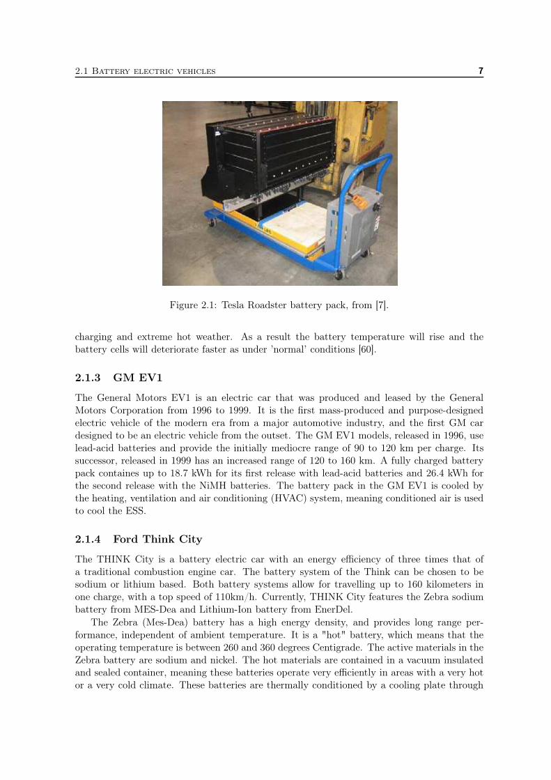
The Tesla Roadster is a prototype for the high-performance BEV auto industry. The batterypack of the Tesla Roadster electric vehicle is one of the largest and technically most advancedlithium ion (Li-ion) battery packs in the world. It is capable of delivering enough powerto accelerate the Tesla Roadster from 0 to 100 km/h in about 4 seconds. Meanwhile, thebattery stores enough energy for the vehicle to travel more than 320 kilometres (based on EPAcity/highway cycle) without recharging, something no production electric vehicle in historycan claim. Details about the design of the Tesla Roadster’s Li-ion battery pack is discussedin [7]. This battery pack has been under development and refinement for over three years andis the cornerstone of the Tesla Roadster.
Due to their high energy density, Li-ion batteries have become the batteries of choice inmost EVs [32, 61]. However, even with this high energy density, the Li-ion batteries in theTesla Roadster only store the energy equivalent of about 8 liters of gasoline; a very smallamount of energy for a typical vehicle. The pack operates at a nominal 375 volts, stores about53 kWh of electric energy, and delivers up to 200 kW of electric power. Due to the power andenergy capabilities of the pack, safety must be considered a primary criterion in the pack’sdesign and architecture.
The battery pack in the Tesla Roadster is comprised of about 6800 so-called 18650 cells, i.e.a small form factor battery cell of measurements of 18mm by 65mm length (hence its name).These cells are all packaged in steel cans, which provide structural rigidity and strength andoffer good thermal conductivity. The dissipation of heat from a cell both extends battery lifeand helps maintain the pack at an even temperature. With a charge/discharge efficiency ofapproximately 95%, the heat generation per cycle will be approximately 2.5 kWh.
Figure 2.1 shows the complete battery pack on a cart. Note the tubes and manifoldextending out of the battery pack at its lower long edge. These are used to circulate coolingfluid (a 50/50 mix of water and glycol) throughout the pack via sealed fluid paths. This enablesthe Roadster to keep the cells thermally balanced. This cooling system design is especiallyeffective because thousands of small cells are combined, rather than several large ones to buildan energy storage system (ESS), dramatically increasing the surface to volume ratio. Surfacearea is essential to cooling batteries since the surface is where heat is removed. Also, becauseof their small size, each cell is able to quickly redistribute heat within and shed heat to theambient environment making it essentially isothermal. Furthermore, this cooling architectureavoids "hot spots" which can lead to failures in large battery modules.
2.1.2 Nissan Leaf
The Nissan Leaf (also formatted "LEAF" as acronym for Leading, Environmentally friendly,Affordable, Family car) is a compact 5-door hatchback electric car to be produced by Nissan.According to the manufacturer, the Leaf’s all-electric range is 160 km in city driving. Salesare scheduled to begin in December 2010.
The lithium-ion battery pack holds 24kWh of energy and is rated to deliver power up to90 kW (120 hp). The pack contains air-cooled, stacked laminar battery cells with lithiummanganate cathodes. The battery pack is expected to retain 70 to 80% of its capacity after10 years; the battery pack’s lifespan depends on how often (440-volt) fast charging is usedand on environmental factors such as extreme hot weather. This is the result of the thermalmanagement system which can not dissipate the heat generated in the battery during fast
2.1 Battery electric vehicles 7
Figure 2.1: Tesla Roadster battery pack, from [7].
charging and extreme hot weather. As a result the battery temperature will rise and thebattery cells will deteriorate faster as under ’normal’ conditions [60].
2.1.3 GM EV1
The General Motors EV1 is an electric car that was produced and leased by the GeneralMotors Corporation from 1996 to 1999. It is the first mass-produced and purpose-designedelectric vehicle of the modern era from a major automotive industry, and the first GM cardesigned to be an electric vehicle from the outset. The GM EV1 models, released in 1996, uselead-acid batteries and provide the initially mediocre range of 90 to 120 km per charge. Itssuccessor, released in 1999 has an increased range of 120 to 160 km. A fully charged batterypack containes up to 18.7 kWh for its first release with lead-acid batteries and 26.4 kWh forthe second release with the NiMH batteries. The battery pack in the GM EV1 is cooled bythe heating, ventilation and air conditioning (HVAC) system, meaning conditioned air is usedto cool the ESS.
2.1.4 Ford Think City
The THINK City is a battery electric car with an energy efficiency of three times that ofa traditional combustion engine car. The battery system of the Think can be chosen to besodium or lithium based. Both battery systems allow for travelling up to 160 kilometers inone charge, with a top speed of 110km/h. Currently, THINK City features the Zebra sodiumbattery from MES-Dea and Lithium-Ion battery from EnerDel.
The Zebra (Mes-Dea) battery has a high energy density, and provides long range per-formance, independent of ambient temperature. It is a "hot" battery, which means that theoperating temperature is between 260 and 360 degrees Centigrade. The active materials in theZebra battery are sodium and nickel. The hot materials are contained in a vacuum insulatedand sealed container, meaning these batteries operate very efficiently in areas with a very hotor a very cold climate. These batteries are thermally conditioned by a cooling plate through
8 2 Current EV’s
which ambient air is circulated, between each second cell. The fan for cooling and an Ohmicheater for heating the battery pack, are controlled by the battery management interface forthermal management [14]. However, since this battery must be maintained at the mentionedtemperature, it must be plugged in when not in use. If it is assumed that the power require-ments to do this is 80W and that the car is parked for 80% of the time this will come down toa energy usage of 560 kWh per year, which seriously reduces the efficiency of these batteries.
The lithium battery operates at ambient temperatures. This means that the car does nothave to be plugged in when not in use. The lithium based battery pack is supplied by EnerDelIt provides the battery pack in a stacked design which provides a variety of options for cooling,which allows for optimum thermal management, performance and safety. At the Think Citywebsite no reference regarding the cooling of the Li-ion battery is provided, though [56,58]
2.1.5 Other BEVs
Multiple experimental BEVs and converted ICE vehicles exist which have battery packs thatare cooled passively by air. In most cases this leads to 10 – 20 K increase with respect toambient temperature. Examples of ICE vehicles that are converted to BEVs are the VW GolfECE of Essent, see [40] and the VW Lupo EL of the Eindhoven University of Technology(TU/e), see [8, 41].
2.2 Hybrid electric vehicles
A hybrid vehicle has two or more power sources, and there are a large number of possiblevariations. The most common types of hybrid vehicle combine an internal combustion enginewith a battery and an electric motor and generator. A hybrid vehicle can either be a series,a parallel, or a series-parallel hybrid. In the former the vehicle is driven by the electromotorwhich is supplied with energy by the battery, by the IC driven generator unit, or by both. Inthe second the vehicle can either be driven by the ICE working directly through a transmissionsystem to the wheels, by one or more electric motors, or by both. In the latter case, both theICE and the electromotor can drive the vehicle and the electromotor can be supplied withenergy by a battery and by the ICE [36,46].
Thermal issues are of more concern in HEV battery packs relative to BEV packs, becauseof higher power and more aggressive charge/discharge profiles [48]. On today’s market severalhybrid electric vehicles are available, three of them are discussed, these are
• Chevrolet Volt
• Toyota Prius
• Honda Insight
2.2.1 Chevrolet Volt
The Chevrolet Volt (the commercial successor of the GM EV1) is an electric vehicle witha range extender, or a so-called plug-in hybrid electric vehicle (PHEV). The Volt runs onelectricity from its battery and when the battery is depleted it runs on electricity created froma gas-generator, making it a series hybrid. The Volt can drive up to 64 kilometres with a
2.2 Hybrid electric vehicles 9
full battery, totally gas and emission free. After the 64 km, its gas-powered, range-extendinggenerator automatically kicks in to provide electrical power.
Energy is stored on board in a 16-kWh, "t"-shaped lithium-ion battery. The batterypowers the electric drive unit, which is capable of meeting full vehicle speed and accelerationperformance while driving the car electrically.
The battery pack of the Chevrolet Volt is made up of more than 200 rectangular cellsarranged in a series-parallel configuration. Computer systems monitor the battery cells tomake sure everything is working correctly. Each battery cell is encased in a polymer coatedaluminum package to withstand harsh climates. A liquid thermal cooling and heating systemkeeps the battery at a comfortable temperature as it is being charged and discharged [57].
2.2.2 Toyota Prius
The most well known full hybrid might be the Toyota Prius. The Prius first went on sale inJapan in 1997, making it the first mass-produced hybrid vehicle. Power to the wheels canbe provided solely by a (274 Volt) Nickel Metal Hydride (NiMH) battery pack through theelectric motor, directly from the gasoline engine, or from a combination of both the electricmotor and the gasoline engine. The battery pack can be recharged directly by energy fromthe wheels powering the motor (regenerative braking) or from excess energy from the gasolineengine – which turns the generator [63]. Hence, the Toyota Prius is a series-parallel hybrid.
The Prius is equipped with a permanent magnet AC electric motor and a 274 Volt NiMHbattery pack. However, there have been done some tests with Li-ion battery packs as well. thehigh power electric drive system and the power electronics are cooled by a (low temperature)liquid cooling loop, whereas the ICE is cooled by a separate (high temperature) cooling loop[25].
An earlier version of the Prius supplied conditioned air from the cabin as thermal manage-ment for cooling the batteries. Outside air was conditioned (heated or cooled) by the vehicle’sthermal comfort system, i.e. the HVAC system, to a level comfortable for the driver. Thisapproach has the advantage of providing air that is not only comfortable to the passenger(s),but also ideal for use in heating or cooling the NiMH batteries.
To maintain a uniform temperature distribution in the battery pack, a parallel airflowscheme was used, rather than a series configuration. In a parallel configuration, each moduleis set up to receive the same amount of airflow and thus the same cooling, [63].
2.2.3 Honda Insight
The Honda Insight is a parallel hybrid-electric vehicle. It is a two-seater with a lightweightaluminum body that is powered by Honda’s Integrated Motor Assist (IMA) powertrain.
The Insight’s IMA is powered by a flat, NiMH battery pack located below the cargo floorbetween the rear wheels. The 84 module battery provides a nominal system voltage of 100.8V with a nominal capacity of 5.75 Ah. The battery is recharged automatically by scavengingengine power, when needed, and by regenerative braking when the car is decelerating. Thepower management electronics, battery modules, and cooling system are all self-containedwithin the IMA battery pack.
The battery pack temperature is conditioned by forced air. The forced air is routed fromthe passenger compartment to an air inlet, through the pack, and then exits the pack by beingindirectly exhausted outside the car. Since the air temperature is near the passenger comfort
10 2 Current EV’s
level, the forced air can provide a cooling effect in hotter weather and a warming effect incolder weather.
The temperature management system will attempt to accomplish two main goals: (i)maintain a reasonable temperature differential across the cells and (ii) keep the pack belowa maximum temperature (usually 50-60◦C for NiMH). The temperature management systemcomprises the fan control for air-cooling and the battery control to manage heat generation,i.e. if the battery temperature is increasing too fast, the required energy is generated by theICE and not from the battery. In [62] this thermal management scheme is analysed. It isconcluded that the thermal management scheme will only work in mild climates and not inhot temperature extremes like Arizona and cold extremes like Canada. The thermal strategythus may seem reasonable, but if harsh conditions are encountered repeatedly, this may leadto failures and/or reduced cycle life for the battery pack. The mild management strategy willsurely reduce the robustness of the pack over time [62].
2.3 Cooling schemes analysed
In the past cooling of Li-ion batteries has been an issue, see [1,61]. However, the most commontype of Li-ion batteries on the market today, LiFePO4 batteries, can be cooled passively byair. Only for high performance vehicles like the Tesla Roadster the batteries require singlephase liquid cooling.
As is mentioned in the foregoing, the cooling of the battery system of the Tesla Roadsteris essentially isothermal. A major advantage of boiling heat transfer in this respect is that thisprocess is isothermal as well. Furthermore this will reduce the weight of the cooling systemas will discussed in Chapter 5.
The battery pack of the Nissan Leaf is actively cooled by air. However, the cooling schemeis not sufficient regarding the lifespan of the battery pack, due to short periods of elevatedtemperature during fast charging or hot weather. Hence, it might be concluded that morecomplex cooling schemes, for example single-phase liquid schemes or boiling heat transferschemes, are required for the car to succeed on the automotive market.
The complexity of cooling schemes may be decreased by implementing a passive coolingsystem based on phase transition, like the pool-boiling system discussed in [16,53]. As coolingis achieved by natural convection, such system may use less energy as systems based on single-phase cooling schemes, since they require an electrical pump to circulate the coolant whichreduces the allelectric range of the EVs. Moreover, as the waste heat can be recovered, it canbe used to heat the cabin. In this way a boiling-based cooling scheme thus can reduce theauxiliary power requirements, increasing the all electric range as will be discussed in the nextchapter.
For (P)HEVs cooling is more important as will be discussed in Chapter 4. HEVs, therefore,are more often cooled actively by single-phase cooling schemes. In HEV applications batterythermal management by boiling heat transfer thus might be interesting.
3 Energy management in EVs
In the previous chapters, BEVs and HEVs on today’s automotive market are discussed. Wehave seen that the batteries that supply these vehicles with energy do this very efficiently andin principle can be cooled by (passive) air cooling. However, in spite of the major drawback oftoday’s electric vehicles, i.e. their range on one charge, the energy management scheme of EVscan be improved. In many cars a large part of the battery capacity is dissipated in resistors toheat up the interior, due to which the range of the car is decreased even further [41]. In thischapter the energy management scheme of different EVs is discussed and the required energyfor heating or air conditioning (A/C) is given.
3.1 Energy requirements for driving
In battery electric vehicles (BEVs) all energy required for propulsion of the vehicle is deliveredby a battery pack. Main drawback of this approach is the fact that carrying energy in theform of batteries is 25 to 100 times heavier than petrol, with respect to the volume factorsranging from 10 to 40 apply. In [8] a number of BEV and equivalent ICE cars are compared.The BEVs on todays market have batteries with a capacity ranging from 16 kWh (MitsubishiiMiev) to 53 kWh (Tesla Roadster). The battery must be able to deliver 55 to 60 kW peakpower during acceleration and 10 to 20 kW continuously while driving at constant speed on alevel road with a voltage of 300V or higher. Depending on the size of the battery pack thesepower requirements can be easily met.
In [42] a full electric 1600 kg heavy VW Golf ECE is analysed for power requirementsduring driving with and without auxiliary systems. Without these systems the average powerconsumption during city driving equals about 230 Wh/km. This can be compared with theenergy consumption of the midsized PHEV vehicle in all electric range (AER) mode discussedin [47]. This vehicle has a smaller battery pack as it has a range extending ICE implemented,however, the overall vehicle mass equals 1600 kg as well. Being in AER mode, the vehiclebehaves like a BEV. The energy consumption of this vehicle during the urban dynamometerdriving schedule (UDDS) (city driving conditions) equals 175 - 180 Wh/km, which is of thesame order of magnitude as the energy consumption of the VW Golf ECE.
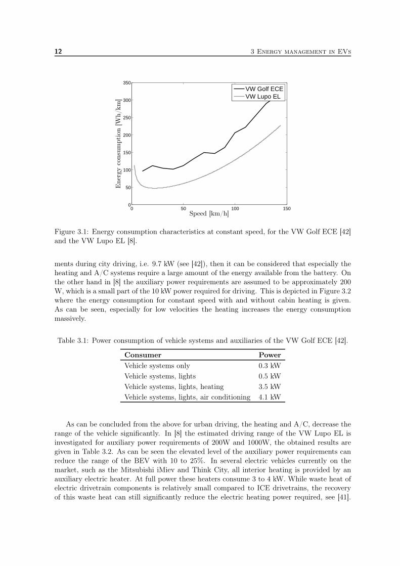
The energy consumption of the VW Golf ECE at constant speed is given in Figure 3.1. Forcomparison the estimated energy consumption of the VW Lupo EL discussed in [8] is givenin this figure as well. Note that the Lupo has an overall weight of 1030 kg, compared to the1600 kg of the VW Golf ECE. The increased power consumption at low velocities is the resultof the auxiliary power requirements of 200 W. It can be seen that the forward velocity withminimal power consumption, in spite of the auxiliary power consumption of 200 W, is about22 km/h which is much lower than that of a diesel car.
3.2 Auxiliary energy requirements
The auxiliary power requirements of the VW Golf variant ECE are given in [42] and given inTable 3.1. If these auxiliary power requirements are compared to the average power require-
11
12 3 Energy management in EVs
0 50 100 1500
50
100
150
200
250
300
350VW Golf ECEVW Lupo EL
Speed [km/h]
Ener
gy
consu
mption
[Wh/km
]
Figure 3.1: Energy consumption characteristics at constant speed, for the VW Golf ECE [42]and the VW Lupo EL [8].
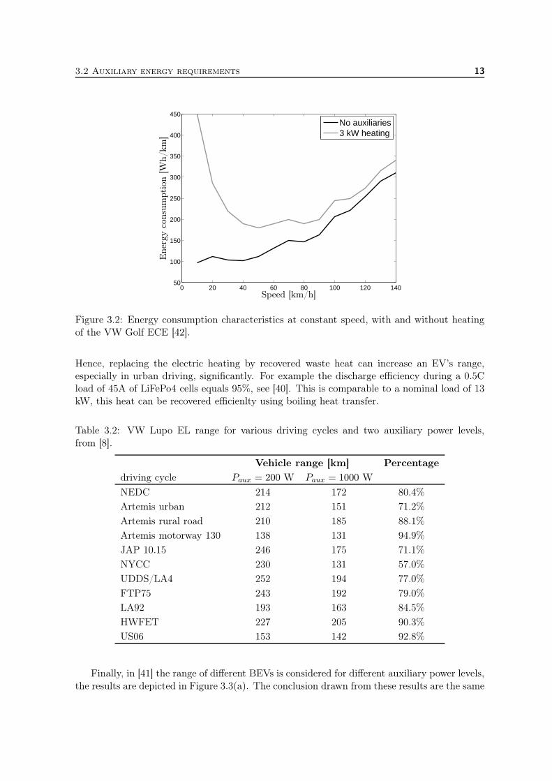
ments during city driving, i.e. 9.7 kW (see [42]), then it can be considered that especially theheating and A/C systems require a large amount of the energy available from the battery. Onthe other hand in [8] the auxiliary power requirements are assumed to be approximately 200W, which is a small part of the 10 kW power required for driving. This is depicted in Figure 3.2where the energy consumption for constant speed with and without cabin heating is given.As can be seen, especially for low velocities the heating increases the energy consumptionmassively.
Table 3.1: Power consumption of vehicle systems and auxiliaries of the VW Golf ECE [42].
Consumer Power
Vehicle systems only 0.3 kW
Vehicle systems, lights 0.5 kW
Vehicle systems, lights, heating 3.5 kW
Vehicle systems, lights, air conditioning 4.1 kW
As can be concluded from the above for urban driving, the heating and A/C, decrease therange of the vehicle significantly. In [8] the estimated driving range of the VW Lupo EL isinvestigated for auxiliary power requirements of 200W and 1000W, the obtained results aregiven in Table 3.2. As can be seen the elevated level of the auxiliary power requirements canreduce the range of the BEV with 10 to 25%. In several electric vehicles currently on themarket, such as the Mitsubishi iMiev and Think City, all interior heating is provided by anauxiliary electric heater. At full power these heaters consume 3 to 4 kW. While waste heat ofelectric drivetrain components is relatively small compared to ICE drivetrains, the recoveryof this waste heat can still significantly reduce the electric heating power required, see [41].
3.2 Auxiliary energy requirements 13
0 20 40 60 80 100 120 14050
100
150
200
250
300
350
400
450No auxiliaries3 kW heating
Speed [km/h]
Ener
gy
consu
mption
[Wh/km
]
Figure 3.2: Energy consumption characteristics at constant speed, with and without heatingof the VW Golf ECE [42].
Hence, replacing the electric heating by recovered waste heat can increase an EV’s range,especially in urban driving, significantly. For example the discharge efficiency during a 0.5Cload of 45A of LiFePo4 cells equals 95%, see [40]. This is comparable to a nominal load of 13kW, this heat can be recovered efficienlty using boiling heat transfer.
Table 3.2: VW Lupo EL range for various driving cycles and two auxiliary power levels,from [8].
Vehicle range [km] Percentage
driving cycle Paux = 200 W Paux = 1000 W
NEDC 214 172 80.4%
Artemis urban 212 151 71.2%
Artemis rural road 210 185 88.1%
Artemis motorway 130 138 131 94.9%
JAP 10.15 246 175 71.1%
NYCC 230 131 57.0%
UDDS/LA4 252 194 77.0%
FTP75 243 192 79.0%
LA92 193 163 84.5%
HWFET 227 205 90.3%
US06 153 142 92.8%
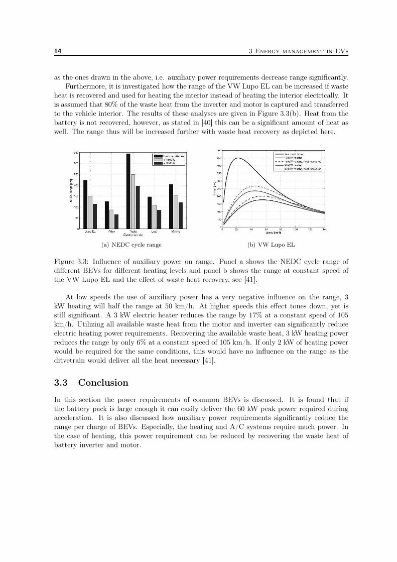
Finally, in [41] the range of different BEVs is considered for different auxiliary power levels,the results are depicted in Figure 3.3(a). The conclusion drawn from these results are the same
14 3 Energy management in EVs
as the ones drawn in the above, i.e. auxiliary power requirements decrease range significantly.Furthermore, it is investigated how the range of the VW Lupo EL can be increased if waste
heat is recovered and used for heating the interior instead of heating the interior electrically. Itis assumed that 80% of the waste heat from the inverter and motor is captured and transferredto the vehicle interior. The results of these analyses are given in Figure 3.3(b). Heat from thebattery is not recovered, however, as stated in [40] this can be a significant amount of heat aswell. The range thus will be increased further with waste heat recovery as depicted here.
(a) NEDC cycle range (b) VW Lupo EL
Figure 3.3: Influence of auxiliary power on range. Panel a shows the NEDC cycle range ofdifferent BEVs for different heating levels and panel b shows the range at constant speed ofthe VW Lupo EL and the effect of waste heat recovery, see [41].
At low speeds the use of auxiliary power has a very negative influence on the range, 3kW heating will half the range at 50 km/h. At higher speeds this effect tones down, yet isstill significant. A 3 kW electric heater reduces the range by 17% at a constant speed of 105km/h. Utilizing all available waste heat from the motor and inverter can significantly reduceelectric heating power requirements. Recovering the available waste heat, 3 kW heating powerreduces the range by only 6% at a constant speed of 105 km/h. If only 2 kW of heating powerwould be required for the same conditions, this would have no influence on the range as thedrivetrain would deliver all the heat necessary [41].
3.3 Conclusion
In this section the power requirements of common BEVs is discussed. It is found that ifthe battery pack is large enough it can easily deliver the 60 kW peak power required duringacceleration. It is also discussed how auxiliary power requirements significantly reduce therange per charge of BEVs. Especially, the heating and A/C systems require much power. Inthe case of heating, this power requirement can be reduced by recovering the waste heat ofbattery inverter and motor.
4 Thermal Issues in EVs
In this section the thermal issues that occur in electric vehicles are discussed. To two majorthermal issues are the thermal management of the battery system and the cooling scheme ofthe high power switching devices required for fast acceleration of the EVs.
4.1 Thermal management of the ESS
The performance and life-cycle costs of EVs depend inherently on energy storage systems (ESS)such as batteries. Battery pack performance directly affects the all-electric range, power foracceleration, fuel economy, and charge acceptance during energy recovery from regenerativebraking. Because the battery pack cost, durability, and life also affect the cost and reliabilityof the vehicle, any parameter that affects the battery pack must be optimized. Temperatureand temperature uniformity have a strong influence on battery pack lifespan and to less extendperformance and consequently, that of EVs, [44, 49].
All the modules in the pack should be operated within the optimum temperature rangesuitable for the particular electrochemical couple used. Especially, since the optimum temper-ature range for the battery operation (e.g. 25◦C to 45◦C) is much narrower than the specifiedoperating temperature for the vehicle (e.g. -30◦C to 60◦C), this can be a challenge [45].
Because HEV batteries have high specific power and undergo aggressive charging/dischargingprofiles, thermal issues in a HEV pack are of more concern than in BEV packs. For this reason,HEV battery packs require more effective thermal management systems like those applyingboiling heat transfer.
Most of todays BEVs are equipped with Li-ion battery packs that are cooled (passively)by air. Only if the battery pack must supply a high-performance BEV like the Tesla Roadster,or fast charging schemes are used to charge the battery pack, an active thermal managementscheme is required. Boiling heat transfer might be applicable in such EVs. Especially if theBEV is equipped with a large battery pack (which is necessary for an acceptable allelectricrange) passive air cooling seems to suffice, however. The batteries generate a small amountof heat during normal operation and temperature only exceeds the ambient temperature by10 – 20K [40, 42]. This does not result in decreased battery performance, however, it doesaccelerate cell deterioration and thermal management may in the long run thus turn out to bemore effective than passive air cooling. In [50] this is investigated in terms of capacity fade ofthe Sony 18650 (1.8 Ah) Li-ion cells by cycling the ESS on elevated temperatures. The cellslost 31% and 36% of their initial capacity after 800 cycles at 25◦C and 45◦C, respectively.For a temperature of 50◦C this equalled up to 50% after 600 cycles and even 70% after 500cycles for temperatures at 55◦C. Allthough, the most commonly used battery, LiFePO4 havenot been subject to such analysis, analogous results might be obtained.
Next to maintaining the battery’s temperature within range, another important parameterwith respect to the battery performance and lifespan and thus the replacement frequency, isthe module temperature uniformity, since if the cells and modules in the pack are at differenttemperatures, each module will be charged/discharged slightly differently during each cycle.After several cycles, modules in the pack will become unbalanced, degrading the pack’s per-formance [48]. Hence, especially in consideration of cycle life of the battery pack a thermal
15
16 4 Thermal Issues in EVs
management/homogenisation scheme is indispensable. Boiling heat transfer allows for ther-mal homogenisation very effectively as it allows for high heat fluxes at pre-defined (constant)temperatures, as will be discussed in the next chapter. Other phase-change heat transfer ap-plications available for thermal homogenisation is solid-liquid phase change. Solid-liquid phasechange is already employed using phase-change materials (PCM) in thermal energy storage(TES) schemes in EVs [2, 33, 38]. As opposed to PCM schemes using boiling heat transfer,the consumed heat can be transported through – and released elsewhere in – the vehicle moreeasily. Thus enabling more efficient use of the consumed waste heat, application of TES is notpossible though.
The importance of thermal management in battery packs for EV application has been anissue for all kinds of batteries. As a result a number of thermal management schemes have beeninvestigated for all kind of battery systems. For example in [33, 38] a thermal managementsystem that incorporates a phase change material (PCM) is considered for a Li-ion batterypack. Other heat dissipation designs for Li-ion batteries are investigated in [61]. The coolingof (valve regulated) lead-acid batteries is discussed in [37] and [5], and a water cooled nickelmetal hydride (NiMH) battery system is discussed in [22].
A thermal management system may use (i) air for heating, cooling, and ventilation, (ii)liquid for cooling/heating and insulation, (iii) phase change materials for thermal storage, or acombination of these methods. Furthermore, the thermal management system may be passive(only the ambient environment is used) or active (special components provide heating andcooling at cold or hot temperatures) [45, 49].
The additional thermal management requirements associated with electric drive systemsare also a recognized challenge in terms of costs related to the thermal management hardware,not only in terms of dollars but also in weight and size that impact the overall vehicle mass,cargo space, component packaging space and total component count [6].
Here the thermal management via boiling heat transfer has advantageous over PCMs andsingle phase liquid cooling schemes, as very little medium is required to obtain a specific heatflux due to the aggressive nature of the boiling process. Moreover, due to the passive workingprinciple of the boiling process, the use of a bulky electric fan is no longer needed in suchsystems as well.
Moreover, with respect to the allelectric range of EV’s it is undesirable for the A/C systemto use much energy. Efficient heat transfer methods thus must be applied to cool the ambientair, see [35]. As a result, more advanced cooling schemes or heat transfer mechanisms will beused in future EVs. Such an efficient heat transfer mechanism can be based on the pool-boilingmodel that is investigated in [16, 52, 53], this will be discussed in Chapter 5.
4.2 Overheating of insulated gate bipolar transistors
An electrical motor drive consists of a power electronic converter an the associated controller.A power converter is made of high-power fast-acting semiconductor devices. An electric switchcan change an electric circuit configuration by switching states from on to off and vice versa.The ideal switch, exhibits no voltage drop across the devices when it conducts and switchesinstantaneously. In practice both properties can not be reached, though.
There are several of these switches, for example the bipolar junction transistor (BJT) hashigh power ratings and excellent conduction characteristics, however, the base drive circuitis complicated because it is a current-driven device. The metal oxide semiconductor field
4.2 Overheating of insulated gate bipolar transistors 17
effect transistor (MOSFET) is a voltage-driven device, as a result, the gate drive circuitsare much simpler. Its frequency is much higher compared to that of a BJT, however, themaximum available device power ratings would be much smaller for the former. To combinethe advantageous properties of the MOSFET and the BJT, the insulated gate bipolar transistor(IGBT) has been invented. These are the devices most commonly used in EVs nowadays [26].
IGBT temperature must be maintained below a critical level. During the device, ON state,OFF state, turn-on and trun-off, a significant amount of power is produced by the flowingcurrent and must be dissipated to the surroundings to prevent the temperature from rising toa level at which device performance is unsatisfactory or ceases altogether. In EVs the chipsare required to drive electric motors, switching large amounts of power from the battery packto electrical coils needed to accelerate the vehicle. The devices also are needed for regenerativebraking; during fast charging of the battery; to convert electrical current to run accessoriesin the vehicle; and to convert AC to DC to charge the battery from a plug-in line. The high-power devices produce about four times as much heat as a conventional computer chip, alsosee [31].
To prevent overheating of IGBTs a new cooling method based on micro-channel flow boilingis proposed on the website [59]. The positive properties of micro-channel flow boiling discussedin [15] will be employed in that case. Of course boiling heat transfer is also applicable in thiscontext. Important in this respect is that pool boiling has essential similarities with micro-channel flow boiling (relevant in many micro-fluidics applications) [27–30, 55]. Thus, thesedevices may also be cooled by a pool-boiling system as described in [16, 52, 53].

18 4 Thermal Issues in EVs
5 Motivation Pool-boiling project
As is demonstrated in the previous chapters, key issues in EVs are massive heat removal(of IGBTs) and thermal homogenisation (of the battery pack). Liquid-vapour phase-changeheat transfer (in particular boiling) affords cooling capacities substantially beyond that ofconventional methods (air/single-phase liquid cooling) and boiling heat transfer can thus im-prove thermal management schemes in EVs. For comparison typical heat transfer rates forforced convection by air are 0.001-0.01 W/cm2K, for forced convection by water that is 0.1-10W/cm2K and boiling heat transfer by water allows for heat transfer coefficients of 0.2-200W/cm2K [39]. Moreover, phase-change heat transfer is an excellent way for thermal ho-mogenisation. Phase change heat transfer occurs, independent of (local) heat-transfer rates,at a given saturation temperature and accompanying saturation pressure. Thermal homogene-ity thus follows from maintaining/restoring the two-phase state at the desired temperature byregulation of the latter or, indirectly, by regulation of the pressure.
Better understanding of the dynamical behaviour of boiling and ways to control this arecrucial, however. The dynamics of liquid-vapour phase-change heat transfer at solid interfaces(boiling; condensation; evaporation) can, at least in a first approach, be adequately repre-sented by that of a pool-boiling system. The principal challenges are maximisation of heattransfer and, closely related to that, thermal homogenisation under dynamic operating condi-tions. These are the two key capabilities that must be strengthened in order for boiling-basedthermal-management schemes to meet tomorrow’s standards.
Hence, fluid boiling affords solutions to both thermal issues in EVs. Moreover, boilinghas, for instance, found first applications in state-of-the-art electronics cooling systems [39]and [44]. However, thermal regulation by boiling is severely limited by the risk of "burn-out"at higher heat fluxes, see [43].
In this chapter the fundamental (pool) boiling aspects will be further discussed. Then theadvantages and disadvantages of use of boiling heat transfer in EVs will be stated. Finally,the objective and strategy of the pool-boiling project mentioned in the introduction will bediscussed.
5.1 Pool-boiling
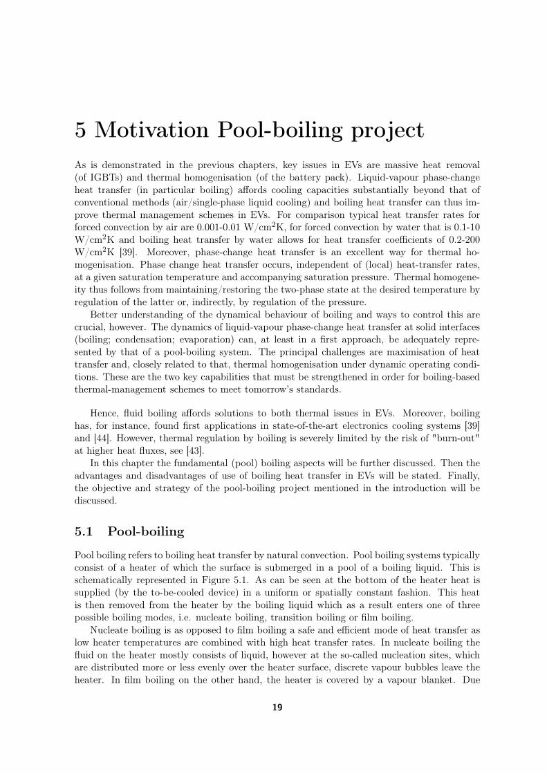
Pool boiling refers to boiling heat transfer by natural convection. Pool boiling systems typicallyconsist of a heater of which the surface is submerged in a pool of a boiling liquid. This isschematically represented in Figure 5.1. As can be seen at the bottom of the heater heat issupplied (by the to-be-cooled device) in a uniform or spatially constant fashion. This heatis then removed from the heater by the boiling liquid which as a result enters one of threepossible boiling modes, i.e. nucleate boiling, transition boiling or film boiling.
Nucleate boiling is as opposed to film boiling a safe and efficient mode of heat transfer aslow heater temperatures are combined with high heat transfer rates. In nucleate boiling thefluid on the heater mostly consists of liquid, however at the so-called nucleation sites, whichare distributed more or less evenly over the heater surface, discrete vapour bubbles leave theheater. In film boiling on the other hand, the heater is covered by a vapour blanket. Due
19
20 5 Motivation Pool-boiling project
Figure 5.1: Schematical representation of a pool-boiling system.
to the insulating properties of the blanket, film boiling is accompanied by high temperaturesand (relative to nucleate boiling) low heat transfer coefficients. The third mode of boiling,transition boiling, is a highly unstable mode characterised by the rapid evolution of localregions that are liquid or vapour rich. Transition boiling, unless actively stabilised, evolvestowards one of the stable boiling modes, i.e. nucleate or film boiling. As a result, the transitionboiling regime will only be entered during the transition form nucleate-to-film or film-to-nucleate boiling.
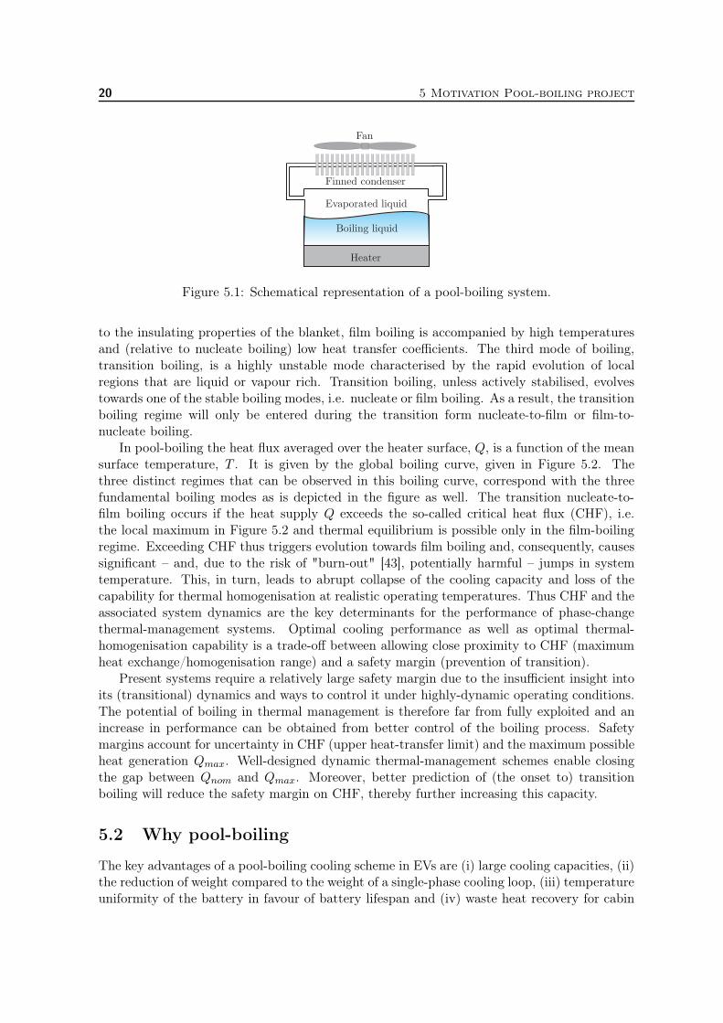
In pool-boiling the heat flux averaged over the heater surface, Q, is a function of the meansurface temperature, T . It is given by the global boiling curve, given in Figure 5.2. Thethree distinct regimes that can be observed in this boiling curve, correspond with the threefundamental boiling modes as is depicted in the figure as well. The transition nucleate-to-film boiling occurs if the heat supply Q exceeds the so-called critical heat flux (CHF), i.e.the local maximum in Figure 5.2 and thermal equilibrium is possible only in the film-boilingregime. Exceeding CHF thus triggers evolution towards film boiling and, consequently, causessignificant – and, due to the risk of "burn-out" [43], potentially harmful – jumps in systemtemperature. This, in turn, leads to abrupt collapse of the cooling capacity and loss of thecapability for thermal homogenisation at realistic operating temperatures. Thus CHF and theassociated system dynamics are the key determinants for the performance of phase-changethermal-management systems. Optimal cooling performance as well as optimal thermal-homogenisation capability is a trade-off between allowing close proximity to CHF (maximumheat exchange/homogenisation range) and a safety margin (prevention of transition).
Present systems require a relatively large safety margin due to the insufficient insight intoits (transitional) dynamics and ways to control it under highly-dynamic operating conditions.The potential of boiling in thermal management is therefore far from fully exploited and anincrease in performance can be obtained from better control of the boiling process. Safetymargins account for uncertainty in CHF (upper heat-transfer limit) and the maximum possibleheat generation Qmax. Well-designed dynamic thermal-management schemes enable closingthe gap between Qnom and Qmax. Moreover, better prediction of (the onset to) transitionboiling will reduce the safety margin on CHF, thereby further increasing this capacity.
5.2 Why pool-boiling
The key advantages of a pool-boiling cooling scheme in EVs are (i) large cooling capacities, (ii)the reduction of weight compared to the weight of a single-phase cooling loop, (iii) temperatureuniformity of the battery in favour of battery lifespan and (iv) waste heat recovery for cabin
5.3 Objective and strategy 21
Figure 5.2: Global boiling curve
heating. To prevent the high power switching devices or IGBTs from overheating, a large heatflux per square cm is required. This can be obtained by applying boiling heat transfer to thechips. As the energy density per unit mass of the coolant is much larger than that of a single-phase cooling loop, the mass of the required coolant in the cooling design is much lower. Sinceboiling heat transfer occurs at a constant temperature irrespective of the heat flux, thermalmanagement by boiling heat transfer allows for optimal temperature homogenisation of thebattery. As boiling heat transfer allows for quick and intensive cooling, the removed heat canbe released easily by condensation to any desired surface, for example for cabin heating.
On the other hand it is quite difficult to design a two-phase cooling loop compared to aone-phase cooling loop, as the coolant flows become turbulent by the interplay between gasand liquid. However, in [44] this problem is solved as well, so in EV application that probablyis possible as well.
5.3 Objective and strategy
Aim of the proposed study is the model-based development of control strategies that safelyfacilitate boiling heat transfer close to CHF under dynamic operating conditions. Such controlstrategies are to form the basis for innovative dynamic thermal-management systems thattightly regulate the boiling process – and thus maximise cooling and thermal-homogenisationcapabilities. The proposed study seeks to regulate the system pressure as a function of the(simulated) temperature distribution within the device.
The study, in a first approach, concentrates on control strategies for a basic 2D/3D pool-boiling system, see Figure 5.1 that control the stability and evolution of (heterogeneous) boilingstates on the fluid-heater interface by regulating the homogeneous heat supply to the heaterelement as a function of the 2D/3D temperature distribution within the heater element. Herethe heat supply is varied instead of the system pressure, as the model is normalised for theCHF. Note that the system pressure sets the CHF. Decreasing (increasing) p stimulates (sup-presses) evaporation and thus will lead to burn-out faster (less fast). Decreasing (increasing)the pressure will thus decrease (increase) the CHF, CHF ∝ p. Although reduction (eleva-tion) of the pressure is accompanied by a temperature decrease (increase), the temperaturedistribution will remain uniform and heat flux per unit area will remain high. By regulat-ing the pressure the system thus can be kept in the efficient nucleate boiling regime. In themodel, decreasing (increasing) the system pressure is modelled by increasing (decreasing) thenormalised heat supply QH , QH ∝ p−1, which will also stimulate (suppress) evaporation.
Control strategies are to be developed by means of the compact 2D/3D pool-boiling model
22 5 Motivation Pool-boiling project
by [51–54]. This model leans on the phenomenological connection between the local boilingmode and the interface temperature and describes the system dynamics entirely in terms of theinternal temperature distribution within the heater. As a result of which the model is called aheater-only model. The potential of this approach has been successfully demonstrated by themodel-based development of a control system for boiling-curve measurements in all boilingregimes [3,4] via the 1D model by [9,24]. Multiple setups for control strategies with differentproperties for the 1D model are discussed in [16, 18]. Furthermore, first attempts to stabilisetransitional states of the 2D version of the model look promising and are discussed in [17].
The principal strength of the heater-only model is that it reduces the complex boilingproblem to a tractable nonlinear heat-transfer problem by establishing a one-to-one connec-tion between the (mesoscopically)1 local temperature and aggregation state. This enables asystem-level description of pool boiling without the need to resolve microscopic (multi-phase)phenomena yet with retention of the essential heterogeneity of the transition regime. Themodel thus facilitates simulation of the dynamical behaviour of the entire boiling system un-der realistic operating conditions and therefore lends itself perfectly for the development ofcontrol strategies.
5.4 Case studies
In [19] some case studies regarding the use of a pool-boiling system to overcome thermal issuesin EVs are done. Here these case studies are given as well. The model to represent the thermalmanagement scheme is based upon the two-dimensional (2D) heater-only model first presentedin [53]. In this model, the boiling fluid is solely modelled by the boundary condition on top ofthe heater. This can be done because of a phenomenological connection between the boilingmode and the interface temperature, cf. [53]. In the following, this model, its equilibria andthe linearisation around them are discussed.
Heater-only model
In the heater-only model, the heat transfer in the 2D rectangular heater H = [0, L]× [0,H] isconsidered – see Fig.5.3(a). The boundary segments of the heater are given by (i) adiabaticsidewalls for x = 0 and x = L, (ii) a constant heat supply extended with the system input bywhich unstable states must be stabilised at y = 0, and (iii) the nonlinear heat extraction bythe boiling process on top of the heater at y = H.
The model describes the heat transfer in terms of the superheat T (x, y, t), i.e. the temper-ature relative to the boiling point of the coolant. The superheat T (x, y, t) within the heateris given by the heat equation
∂T
∂t(x, y, t) = α∇2T (x, y, t), (5.1)
1Here "mesoscopic" means locally averaged in space and time over intervals larger than bubble dimensionsand bubble lifetimes so as to smooth out microscopic short-term fluctuations [43].
5.4 Case studies 23
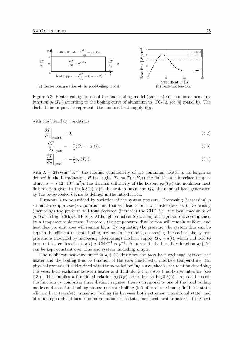
(a) Heater configuration of the pool-boiling model.
0 50 100 1500
5
10
15
20
25
qF(T
F)
QH
Superheat T [K]
Hea
tflux
[W/cm
2]
(b) heat-flux function
Figure 5.3: Heater configuration of the pool-boiling model (panel a) and nonlinear heat-fluxfunction qF (TF ) according to the boiling curve of aluminum vs. FC-72, see [4] (panel b). Thedashed line in panel b represents the nominal heat supply QH .
with the boundary conditions
∂T
∂x
∣∣∣∣x=0,L
= 0, (5.2)
∂T
∂y
∣∣∣∣y=0
= − 1
λ(QH + u(t)), (5.3)
∂T
∂y
∣∣∣∣y=H
= − 1
λqF (TF ), (5.4)
with λ = 237Wm−1K−1 the thermal conductivity of the aluminum heater, L its length asdefined in the Introduction, H its height, TF := T (x,H, t) the fluid-heater interface temper-ature, α = 8.42 · 10−5m2/s the thermal diffusivity of the heater, qF (TF ) the nonlinear heatflux relation given in Fig.5.3(b), u(t) the system input and QH the nominal heat generationby the to-be-cooled device as defined in the introduction.
Burn-out is to be avoided by variation of the system pressure. Decreasing (increasing) pstimulates (suppresses) evaporation and thus will lead to burn-out faster (less fast). Decreasing(increasing) the pressure will thus decrease (increase) the CHF, i.e. the local maximum ofqF (TF ) in Fig. 5.3(b), CHF ∝ p. Although reduction (elevation) of the pressure is accompaniedby a temperature decrease (increase), the temperature distribution will remain uniform andheat flux per unit area will remain high. By regulating the pressure, the system thus can bekept in the efficient nucleate boiling regime. In the model, decreasing (increasing) the systempressure is modelled by increasing (decreasing) the heat supply QH + u(t), which will lead toburn-out faster (less fast), u(t) ∝ CHF−1 ∝ p−1. As a result, the heat flux function qF (TF )can be kept constant over time and system modelling simple.
The nonlinear heat-flux function qF (TF ) describes the local heat exchange between theheater and the boiling fluid as function of the local fluid-heater interface temperature. Onphysical grounds, it is identified with the so-called boiling curve, that is, the relation describingthe mean heat exchange between heater and fluid along the entire fluid-heater interface (see[13]). This implies a functional relation qF (TF ) according to Fig.5.3(b). As can be seen,the function qF comprises three distinct regimes, these correspond to one of the local boilingmodes and associated boiling states: nucleate boiling (left of local maximum; fluid-rich state,efficient heat transfer), transition boiling (in between both extremes; transitional state) andfilm boiling (right of local minimum; vapour-rich state, inefficient heat transfer). If the heat
24 5 Motivation Pool-boiling project
supply exceeds CHF, the nucleate boiling regime ceases to exist, and passing through thetransition boiling regime, the film boiling regime is entered. This is accompanied with amassive increase in temperature and thus is to be avoided in practical applications.
Equilibria of the model
An extensive exposition on the steady states of this model and their stability properties isfurnished in [52, 53]. Below a concise recapitulation is provided.
Steady states T∞(x, y) of (5.1-5.4) are found via application of the method of separationof variables, see [34]. This yields a (formal) solution given by
T∞(x, y) =
∞∑
k=0
Tk
cosh(κky)
cosh(κkH)cos(κkx) +
QH
λ(H − y), (5.5)
with κk = kπ/L and coefficients Tk the spectrum of the Fourier cosine expansion of thetemperature at the fluid-heater interface,
TF,∞(x) := T∞(x,H) =
∞∑
k=0
Tk cos(κkx). (5.6)
These coefficients are determined by the nonlinear Neumann condition at y = H, upon sub-stitution of (5.5) leading to
∞∑
k=0
Tkκk tanh(κkH) cos(κkx)−QH
λ= − 1
λqF (TF,∞), ∀ x ∈ [0, L]. (5.7)
Equation (5.7) is the characteristic equation that determines the particular properties of thesteady states of (5.1-5.4). If Tk = 0 for k > 0, the equilibrium is constant in x-directionand (5.7) simplifies to qF (TF,∞) = QH . As a result, TF,∞ coincides with the intersection(s)between the boiling curve (solid line in Fig.5.3(b)) and the nominal heat-supply (dashedline in Fig.5.3(b)). Here the left and right intersections correspond to stable nucleate andstable film boiling, respectively. The middle intersection corresponds to an unstable transitionboiling equilibrium. These three equilibria are called the homogeneous equilibria as they areuniform in x-direction. All other equilibria are not uniform in x-direction and are called theheterogeneous equilibria. Heterogeneous solutions are characterised by local liquid-rich andlocal vapour-rich regions and thus belong to the transition boiling regime.
The principal objective here is the stabilisation of the unstable homogeneous transitionequilibrium. Without stabilisation of this equilibrium, exceeding the CHF will inherentlyresult in progression to the film boiling regime and burn-out of the to-be-cooled device. Sta-bilisation of this equilibrium, on the other hand, allows for increased heat flux rates andthus increases the efficiency of the cooling device. Because of the non-uniform temperaturedistribution of the heterogeneous equilibria, convergence towards these equilibria results inundesired non-uniform temperature distributions in the battery pack or IGBT and thus is tobe avoided during operation.
Linearisation
Stabilisation of the homogeneous transition boiling equilibrium is investigated in terms of alinearisation of the pool boiling model around this equilibrium. To this end, small deviations
5.4 Case studies 25
v(x, y, t) from the equilibrium T∞(x, y) are considered, i.e. T (x, y, t) = T∞(x, y) + v(x, y, t).Standard linearisation methods readily yield
∂v
∂t(x, y, t) = α∇2v(x, y, t), (5.8)
with the boundary conditions
∂v
∂x
∣∣∣∣x=0,L
= 0, (5.9)
∂v
∂y
∣∣∣∣y=0
= − 1
λu(t), (5.10)
∂v
∂y
∣∣∣∣y=H
= − 1
λγ(x)vF (x), (5.11)
as linear counterpart of (5.1-5.4), where vF (x) := v(x,H) and
γ(x) =dqFdTF
∣∣∣∣TF (x)=TF,∞(x)
. (5.12)
5.4.1 Control strategy
In this section, the control strategy for stabilisation of the pool boiling system is discussed.Burn-out is to be avoided by variation of the system pressure p. In order to keep the heat fluxfunction qF (TF ) constant over time and system modelling simple, this is modelled by uniformvariation u(t) of the heat supply, as discussed in the previous section.
Feedback law
The intended control strategy is a feedback law based on the deviation v(x, y, t) = T (x, y, t)−T∞(x, y) between the heater superheat T (x, y, t) and its desired distribution T∞(x, y). Easilystated, if the temperature inside the heater is lower than the desired value, u(t) is positiveas a result of which boiling is stimulated and lower heat fluxes are generated between heaterand boiling liquid. Consequently, the device is cooled less efficient and heats itself. Whenthe temperature is too high, the input is negative and boiling is suppressed by increasing thepressure, as a result, higher heat fluxes are generated and more heat is extracted from thedevice, cooling it down in the process.
The input can be calculated by evaluating the heaters temperature in only one or twospecific points, however, the aim here is to evaluate the entire temperature profile in the feed-back law in favor of beneficial closed-loop behaviour, i.e. the behaviour of the system with thefeedback law. The heater temperature v(x, y, t) is multiplied with a feedback weightfunctiong(x, y) to be able to give more weight to specific regions within the heater, e.g. the fluid-heaterinterface. As system pressure is equal in the entire boiling chamber, the system input u(t)must be uniform in x-direction. As a result, the term v(x, y, t)g(x, y) must be integrated overthe heater domain, resulting in the feedback law
u(t) =
H∫
0
L∫
0
v(x, y, t)g(x, y)dxdy. (5.13)
26 5 Motivation Pool-boiling project
This means that the controller calculates whether the overall temperature in the heater is toohigh or too low and stimulates or suppresses the boiling process accordingly (specific regionscan be excluded or be given more weight by appropriate choice of g(x, y)). With the feedbackweight function the properties of the feedback law, and thus the closed-loop system, will beprescribed. Furthermore, the temperature inside the heater v(x, y, t) is expressed in a formthat is intimately related to its natural eigenmodes. This means that in x-direction, theeigenmodes of the Laplace operator are taken to represent the profile, i.e. by a Fourier-cosineexpansion. In y-direction, the profile is expressed in the non-periodic variant of this expansion,i.e. the Chebyshev expansion. This control law is discussed in full detail in [17,20], here onlya concise recapitulation is given. The temperature profile in terms of the Chebyshev-Fourierspectrum is given by
v(x, y, t) =
∞∑
k,n=0
vnk(t)φn(θ(y))ρk(x), (5.14)
with vnk the spectral coefficients of v(x, y, t), φn(θ) = cos(n arccos(θ)) is the n-th Chebyshevpolynomial, ρk(x) = cos(κkx) the k-th Fourier cosine polynomial and θ = 2
Hy − 1 is the
computational domain in y-direction, cf. [10]. Note that here an infinite series is considered,meaning no approximation error is introduced in this step. Moreover, if a smooth temperaturefield in the heater is assumed, due to exponential convergence of the Chebyshev-Fourier-cosinespectral coefficients, the system dynamics are mainly prescribed by the ’lower order’ modes,i.e. modes with low n and low k. As a result, the feedback law given by (5.13) only needs tobe based on these ’lower’ modes, as established in [16].
In order to filter these specific modes from the profile v(x, y, t), the feedback weight functiong(x, y) is taken as
g(x, y) =∞∑
q,p=0
gqpφq(θ)wC(θ)ρp(x), (5.15)
with wC(θ) = (1−θ2)−12 the orthogonal weight function of the Chebyshev polynomials, cf. [10]
and gqp the spectral coefficients of the weight function. Due to the orthogonality property ofthe Chebyshev and Fourier polynomials, implementing (5.14) and (5.15) in (5.13) reduces thefeedback law to
u(t) =∞∑
p,q=0
vqp(t)kqp, (5.16)
where kqp =πH8 cqcpgqp and the factor ci = 2 for i = 0 and ci = 1 for i > 0, see [10].
Note that this feedback law enables control of individual Chebyshev-Fourier-cosine modesby appropriate choice of kqp. This so-called modal control scheme thus enables efficient controlof exactly the relevant lower order modes. Meaning that this feedback law practically is a full-state feedback, which significantly outperforms standard P-control for this boiling application[16].
The elements kqp must be determined such that desired/satisfactory closed-loop dynamicsare obtained. This can be done by putting the so-called closed-loop poles of the linearisedsystem at desired/satisfactory locations. To determine these closed-loop poles, a characteristic
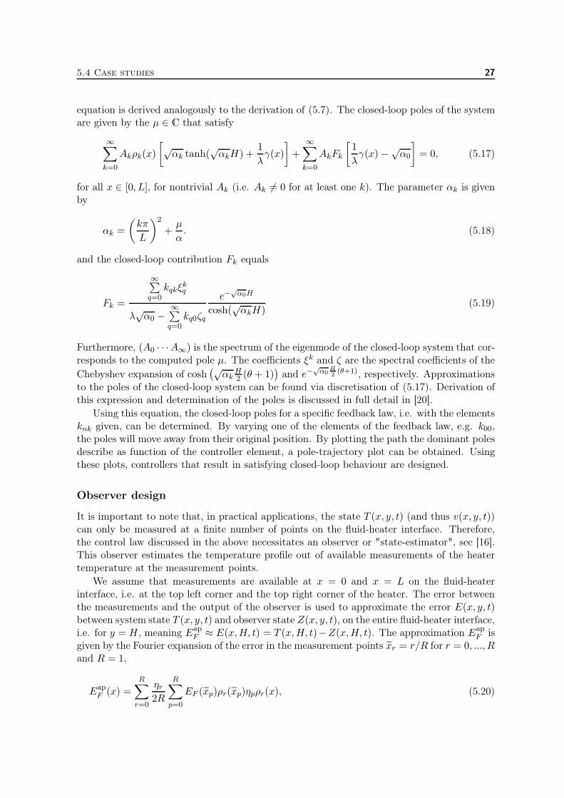
5.4 Case studies 27
equation is derived analogously to the derivation of (5.7). The closed-loop poles of the systemare given by the µ ∈ C that satisfy
∞∑
k=0
Akρk(x)
[√αk tanh(
√αkH) +
1
λγ(x)
]+
∞∑
k=0
AkFk
[1
λγ(x)−√
α0
]= 0, (5.17)
for all x ∈ [0, L], for nontrivial Ak (i.e. Ak 6= 0 for at least one k). The parameter αk is givenby
αk =
(kπ
L
)2
+µ
α. (5.18)
and the closed-loop contribution Fk equals
Fk =
∞∑q=0
kqkξkq
λ√α0 −
∞∑q=0
kq0ζq
e−√α0H
cosh(√αkH)
(5.19)
Furthermore, (A0 · · ·A∞) is the spectrum of the eigenmode of the closed-loop system that cor-responds to the computed pole µ. The coefficients ξk and ζ are the spectral coefficients of the
Chebyshev expansion of cosh(√
αkH2 (θ + 1)
)and e−
√α0
H2(θ+1), respectively. Approximations
to the poles of the closed-loop system can be found via discretisation of (5.17). Derivation ofthis expression and determination of the poles is discussed in full detail in [20].
Using this equation, the closed-loop poles for a specific feedback law, i.e. with the elementsknk given, can be determined. By varying one of the elements of the feedback law, e.g. k00,the poles will move away from their original position. By plotting the path the dominant polesdescribe as function of the controller element, a pole-trajectory plot can be obtained. Usingthese plots, controllers that result in satisfying closed-loop behaviour are designed.
Observer design
It is important to note that, in practical applications, the state T (x, y, t) (and thus v(x, y, t))can only be measured at a finite number of points on the fluid-heater interface. Therefore,the control law discussed in the above necessitates an observer or "state-estimator", see [16].This observer estimates the temperature profile out of available measurements of the heatertemperature at the measurement points.
We assume that measurements are available at x = 0 and x = L on the fluid-heaterinterface, i.e. at the top left corner and the top right corner of the heater. The error betweenthe measurements and the output of the observer is used to approximate the error E(x, y, t)between system state T (x, y, t) and observer state Z(x, y, t), on the entire fluid-heater interface,i.e. for y = H, meaning Eap
F ≈ E(x,H, t) = T (x,H, t)−Z(x,H, t). The approximation EapF is
given by the Fourier expansion of the error in the measurement points xr = r/R for r = 0, ..., Rand R = 1,
EapF (x) =
R∑
r=0
ηr2R
R∑
p=0
EF (xp)ρr(xp)ηpρr(x), (5.20)
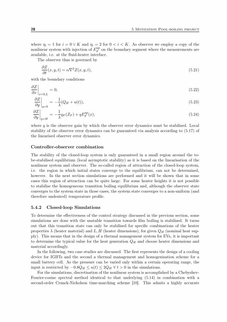
28 5 Motivation Pool-boiling project
where ηi = 1 for i = 0 ∨K and ηi = 2 for 0 < i < K. As observer we employ a copy of thenonlinear system with injection of Eap
F on the boundary segment where the measurements areavailable, i.e. at the fluid-heater interface.
The observer thus is governed by
∂Z
∂t(x, y, t) = α∇2Z(x, y, t), (5.21)
with the boundary conditions
∂Z
∂x
∣∣∣∣x=0,L
= 0, (5.22)
∂Z
∂y
∣∣∣∣y=0
= − 1
λ(QH + u(t)), (5.23)
∂Z
∂y
∣∣∣∣y=H
= − 1
λqF (ZF ) + qEap
F (x), (5.24)
where q is the observer gain by which the observer error dynamics must be stabilised. Localstability of the observer error dynamics can be guaranteed via analysis according to (5.17) ofthe linearised observer error dynamics.
Controller-observer combination
The stability of the closed-loop system is only guaranteed in a small region around the to-be-stabilised equilibrium (local asymptotic stability) as it is based on the linearisation of thenonlinear system and observer. The so-called region of attraction of the closed-loop system,i.e. the region in which initial states converge to the equilibrium, can not be determined,however. In the next section simulations are performed and it will be shown that in somecases this region of attraction can be quite large. For some heater heights it is not possibleto stabilise the homogeneous transition boiling equilibrium and, although the observer stateconverges to the system state in those cases, the system state converges to a non-uniform (andtherefore undesired) temperature profile.
5.4.2 Closed-loop Simulations
To determine the effectiveness of the control strategy discussed in the previous section, somesimulations are done with the unstable transition towards film boiling is stabilised. It turnsout that this transition state can only be stabilised for specific combinations of the heaterproperties λ (heater material) and L,H (heater dimensions), for given QH (nominal heat sup-ply). This means that in the design of a thermal management system for EVs, it is importantto determine the typical value for the heat generation QH and choose heater dimensions andmaterial accordingly.
In the following, two case studies are discussed. The first represents the design of a coolingdevice for IGBTs and the second a thermal management and homogenisation scheme for asmall battery cell. As the pressure can be varied only within a certain operating range, theinput is restricted by −0.8QH ≤ u(t) ≤ 2QH ∀ t > 0 in the simulations.
For the simulations, discretisation of the nonlinear system is accomplished by a Chebyshev-Fourier-cosine spectral method identical to that underlying (5.14) in combination with asecond-order Cranck-Nicholson time-marching scheme [10]. This admits a highly accurate
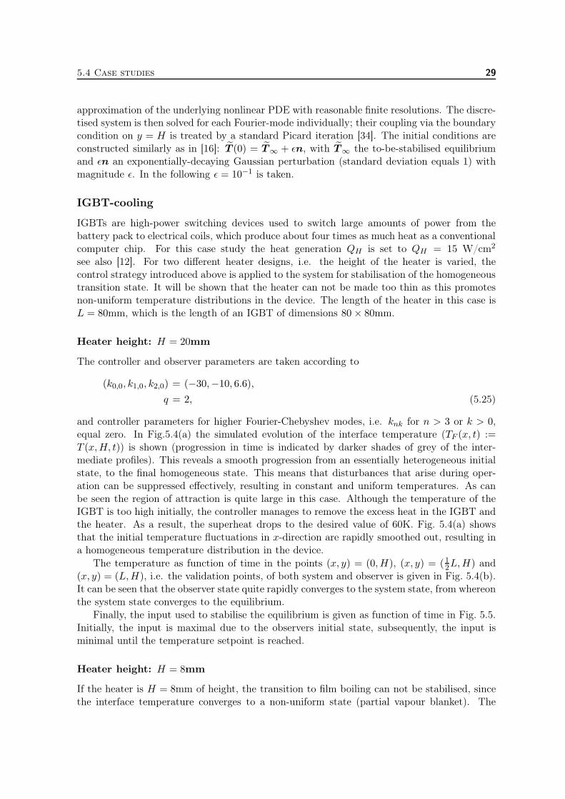
5.4 Case studies 29
approximation of the underlying nonlinear PDE with reasonable finite resolutions. The discre-tised system is then solved for each Fourier-mode individually; their coupling via the boundarycondition on y = H is treated by a standard Picard iteration [34]. The initial conditions areconstructed similarly as in [16]: T (0) = T∞ + ǫn, with T∞ the to-be-stabilised equilibriumand ǫn an exponentially-decaying Gaussian perturbation (standard deviation equals 1) withmagnitude ǫ. In the following ǫ = 10−1 is taken.
IGBT-cooling
IGBTs are high-power switching devices used to switch large amounts of power from thebattery pack to electrical coils, which produce about four times as much heat as a conventionalcomputer chip. For this case study the heat generation QH is set to QH = 15 W/cm2
see also [12]. For two different heater designs, i.e. the height of the heater is varied, thecontrol strategy introduced above is applied to the system for stabilisation of the homogeneoustransition state. It will be shown that the heater can not be made too thin as this promotesnon-uniform temperature distributions in the device. The length of the heater in this case isL = 80mm, which is the length of an IGBT of dimensions 80× 80mm.
Heater height: H = 20mm
The controller and observer parameters are taken according to
(k0,0, k1,0, k2,0) = (−30,−10, 6.6),
q = 2, (5.25)
and controller parameters for higher Fourier-Chebyshev modes, i.e. knk for n > 3 or k > 0,equal zero. In Fig.5.4(a) the simulated evolution of the interface temperature (TF (x, t) :=T (x,H, t)) is shown (progression in time is indicated by darker shades of grey of the inter-mediate profiles). This reveals a smooth progression from an essentially heterogeneous initialstate, to the final homogeneous state. This means that disturbances that arise during oper-ation can be suppressed effectively, resulting in constant and uniform temperatures. As canbe seen the region of attraction is quite large in this case. Although the temperature of theIGBT is too high initially, the controller manages to remove the excess heat in the IGBT andthe heater. As a result, the superheat drops to the desired value of 60K. Fig. 5.4(a) showsthat the initial temperature fluctuations in x-direction are rapidly smoothed out, resulting ina homogeneous temperature distribution in the device.
The temperature as function of time in the points (x, y) = (0,H), (x, y) = (12L,H) and(x, y) = (L,H), i.e. the validation points, of both system and observer is given in Fig. 5.4(b).It can be seen that the observer state quite rapidly converges to the system state, from whereonthe system state converges to the equilibrium.
Finally, the input used to stabilise the equilibrium is given as function of time in Fig. 5.5.Initially, the input is maximal due to the observers initial state, subsequently, the input isminimal until the temperature setpoint is reached.
Heater height: H = 8mm
If the heater is H = 8mm of height, the transition to film boiling can not be stabilised, sincethe interface temperature converges to a non-uniform state (partial vapour blanket). The
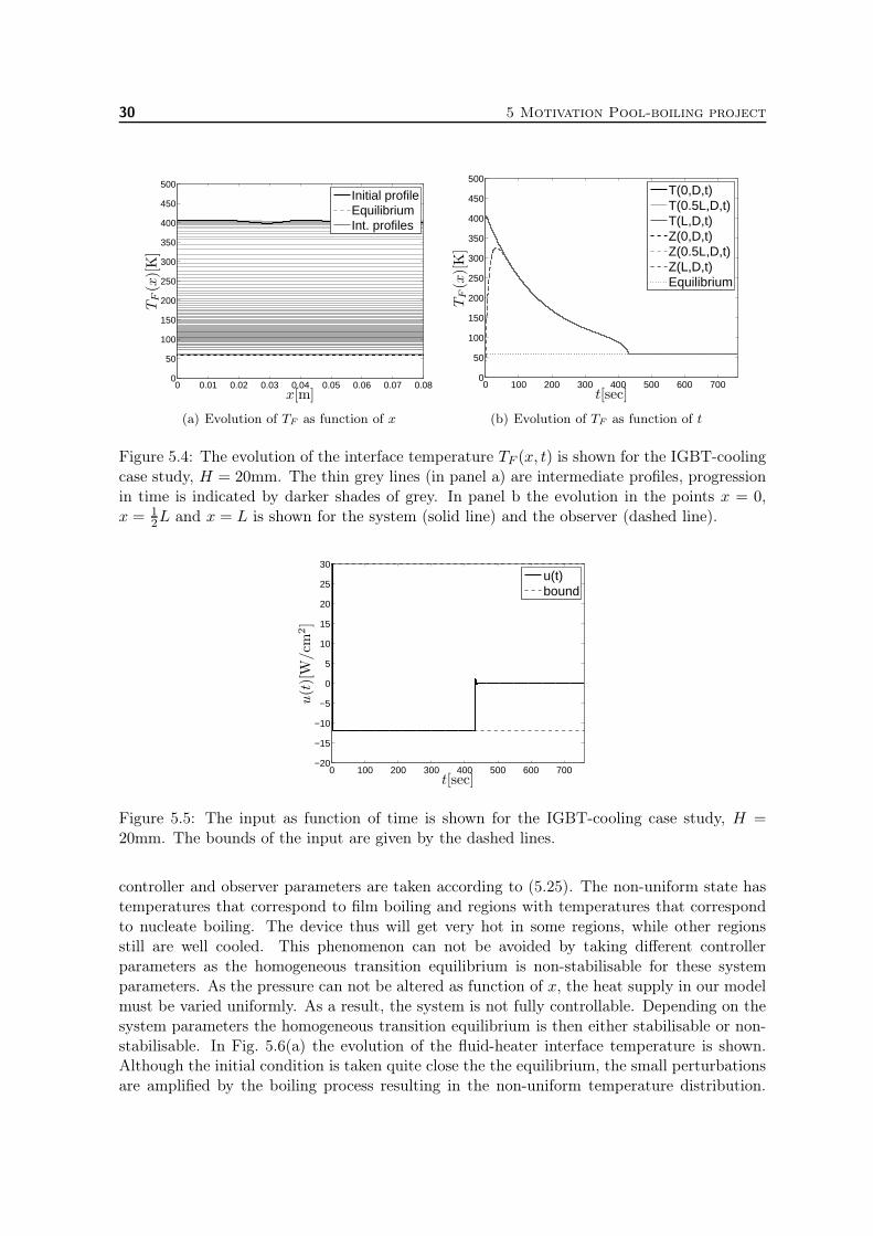
30 5 Motivation Pool-boiling project
0 0.01 0.02 0.03 0.04 0.05 0.06 0.07 0.080
50
100
150
200
250
300
350
400
450
500Initial profileEquilibriumInt. profiles
x[m]
TF(x)[K]
(a) Evolution of TF as function of x
0 100 200 300 400 500 600 7000
50
100
150
200
250
300
350
400
450
500T(0,D,t)T(0.5L,D,t)T(L,D,t)Z(0,D,t)Z(0.5L,D,t)Z(L,D,t)Equilibrium
t[sec]
TF(x)[K]
(b) Evolution of TF as function of t
Figure 5.4: The evolution of the interface temperature TF (x, t) is shown for the IGBT-coolingcase study, H = 20mm. The thin grey lines (in panel a) are intermediate profiles, progressionin time is indicated by darker shades of grey. In panel b the evolution in the points x = 0,x = 1
2L and x = L is shown for the system (solid line) and the observer (dashed line).
0 100 200 300 400 500 600 700−20
−15
−10
−5
0
5
10
15
20
25
30u(t)bound
t[sec]
u(t)[W
/cm
2]
Figure 5.5: The input as function of time is shown for the IGBT-cooling case study, H =20mm. The bounds of the input are given by the dashed lines.
controller and observer parameters are taken according to (5.25). The non-uniform state hastemperatures that correspond to film boiling and regions with temperatures that correspondto nucleate boiling. The device thus will get very hot in some regions, while other regionsstill are well cooled. This phenomenon can not be avoided by taking different controllerparameters as the homogeneous transition equilibrium is non-stabilisable for these systemparameters. As the pressure can not be altered as function of x, the heat supply in our modelmust be varied uniformly. As a result, the system is not fully controllable. Depending on thesystem parameters the homogeneous transition equilibrium is then either stabilisable or non-stabilisable. In Fig. 5.6(a) the evolution of the fluid-heater interface temperature is shown.Although the initial condition is taken quite close the the equilibrium, the small perturbationsare amplified by the boiling process resulting in the non-uniform temperature distribution.
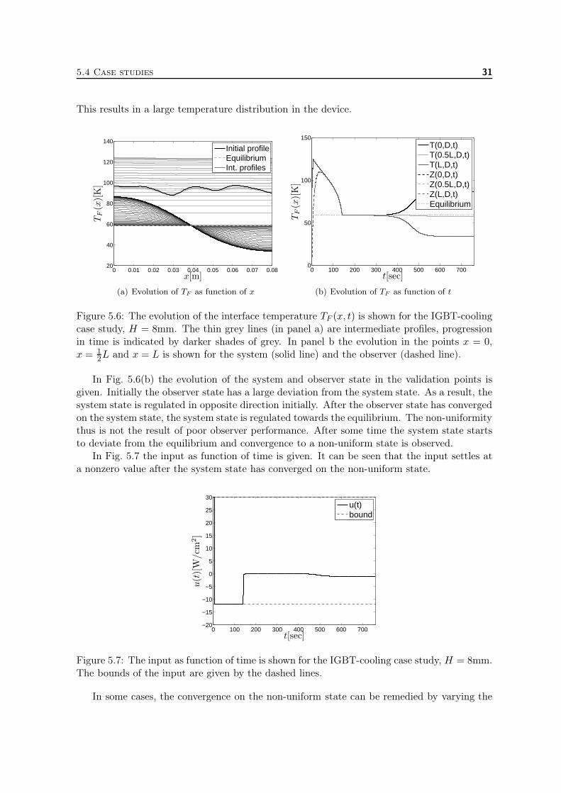
5.4 Case studies 31
This results in a large temperature distribution in the device.
0 0.01 0.02 0.03 0.04 0.05 0.06 0.07 0.0820
40
60
80
100
120
140Initial profileEquilibriumInt. profiles
x[m]
TF(x)[K]
(a) Evolution of TF as function of x
0 100 200 300 400 500 600 7000
50
100
150T(0,D,t)T(0.5L,D,t)T(L,D,t)Z(0,D,t)Z(0.5L,D,t)Z(L,D,t)Equilibrium
t[sec]
TF(x)[K]
(b) Evolution of TF as function of t
Figure 5.6: The evolution of the interface temperature TF (x, t) is shown for the IGBT-coolingcase study, H = 8mm. The thin grey lines (in panel a) are intermediate profiles, progressionin time is indicated by darker shades of grey. In panel b the evolution in the points x = 0,x = 1
2L and x = L is shown for the system (solid line) and the observer (dashed line).
In Fig. 5.6(b) the evolution of the system and observer state in the validation points isgiven. Initially the observer state has a large deviation from the system state. As a result, thesystem state is regulated in opposite direction initially. After the observer state has convergedon the system state, the system state is regulated towards the equilibrium. The non-uniformitythus is not the result of poor observer performance. After some time the system state startsto deviate from the equilibrium and convergence to a non-uniform state is observed.
In Fig. 5.7 the input as function of time is given. It can be seen that the input settles ata nonzero value after the system state has converged on the non-uniform state.
0 100 200 300 400 500 600 700−20
−15
−10
−5
0
5
10
15
20
25
30u(t)bound
t[sec]
u(t)[W
/cm
2]
Figure 5.7: The input as function of time is shown for the IGBT-cooling case study, H = 8mm.The bounds of the input are given by the dashed lines.
In some cases, the convergence on the non-uniform state can be remedied by varying the
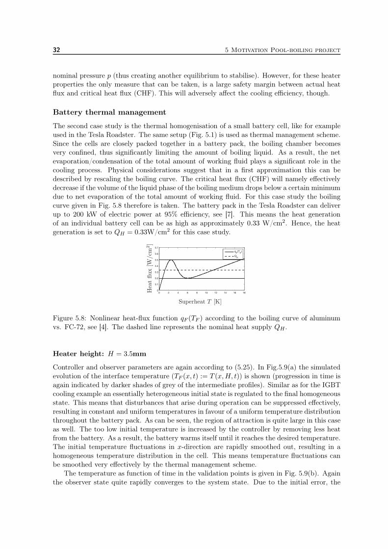
32 5 Motivation Pool-boiling project
nominal pressure p (thus creating another equilibrium to stabilise). However, for these heaterproperties the only measure that can be taken, is a large safety margin between actual heatflux and critical heat flux (CHF). This will adversely affect the cooling efficiency, though.
Battery thermal management
The second case study is the thermal homogenisation of a small battery cell, like for exampleused in the Tesla Roadster. The same setup (Fig. 5.1) is used as thermal management scheme.Since the cells are closely packed together in a battery pack, the boiling chamber becomesvery confined, thus significantly limiting the amount of boiling liquid. As a result, the netevaporation/condensation of the total amount of working fluid plays a significant role in thecooling process. Physical considerations suggest that in a first approximation this can bedescribed by rescaling the boiling curve. The critical heat flux (CHF) will namely effectivelydecrease if the volume of the liquid phase of the boiling medium drops below a certain minimumdue to net evaporation of the total amount of working fluid. For this case study the boilingcurve given in Fig. 5.8 therefore is taken. The battery pack in the Tesla Roadster can deliverup to 200 kW of electric power at 95% efficiency, see [7]. This means the heat generationof an individual battery cell can be as high as approximately 0.33 W/cm2. Hence, the heatgeneration is set to QH = 0.33W/cm2 for this case study.
Figure 5.8: Nonlinear heat-flux function qF (TF ) according to the boiling curve of aluminumvs. FC-72, see [4]. The dashed line represents the nominal heat supply QH .
Heater height: H = 3.5mm
Controller and observer parameters are again according to (5.25). In Fig.5.9(a) the simulatedevolution of the interface temperature (TF (x, t) := T (x,H, t)) is shown (progression in time isagain indicated by darker shades of grey of the intermediate profiles). Similar as for the IGBTcooling example an essentially heterogeneous initial state is regulated to the final homogeneousstate. This means that disturbances that arise during operation can be suppressed effectively,resulting in constant and uniform temperatures in favour of a uniform temperature distributionthroughout the battery pack. As can be seen, the region of attraction is quite large in this caseas well. The too low initial temperature is increased by the controller by removing less heatfrom the battery. As a result, the battery warms itself until it reaches the desired temperature.The initial temperature fluctuations in x-direction are rapidly smoothed out, resulting in ahomogeneous temperature distribution in the cell. This means temperature fluctuations canbe smoothed very effectively by the thermal management scheme.
The temperature as function of time in the validation points is given in Fig. 5.9(b). Againthe observer state quite rapidly converges to the system state. Due to the initial error, the

5.4 Case studies 33
0 0.01 0.02 0.03 0.04 0.05 0.062.5
3
3.5
4
4.5
5Initial profileEquilibriumInt. profiles
x[m]
TF(x)[K]
(a) Evolution of TF as function of x
0 10 20 30 40 500
0.5
1
1.5
2
2.5
3
3.5
4
4.5
5T(0,D,t)T(0.5L,D,t)T(L,D,t)Z(0,D,t)Z(0.5L,D,t)Z(L,D,t)Equilibrium
t[sec]
TF(x)[K]
(b) Evolution of TF as function of t
Figure 5.9: The evolution of the interface temperature TF (x, t) is shown for the battery-coolingcase study, H = 3.5mm. The thin grey lines (in panel a) are intermediate profiles, progressionin time is indicated by darker shades of grey. In panel b the evolution in the points x = 0,x = 1
2L and x = L is shown for the system (solid line) and the observer (dashed line).
system overshoots its equilibrium value, however. After the observer state has reached theequilibrium the system state is regulated towards the equilibrium as well.
Finally, the input used to stabilise the equilibrium is given as function of time in Fig. 5.10.Initially, the input is taken maximal, then minimal and subsequently it smoothly convergesto zero as the system state converges on the equilibrium.
0 10 20 30 40 50−0.5
0
0.5
1u(t)bound
t[sec]
u(t)[W
/cm
2]
Figure 5.10: The input as function of time is shown for the battery-cooling case study, H =3.5mm. The bounds of the input are given by the dashed lines.
Heater height: H = 1.75mm
If the heater is H = 1.75mm of height, the transition to film boiling can not be stabilised,since the interface temperature converges to a non-uniform state (partial vapour blanket).
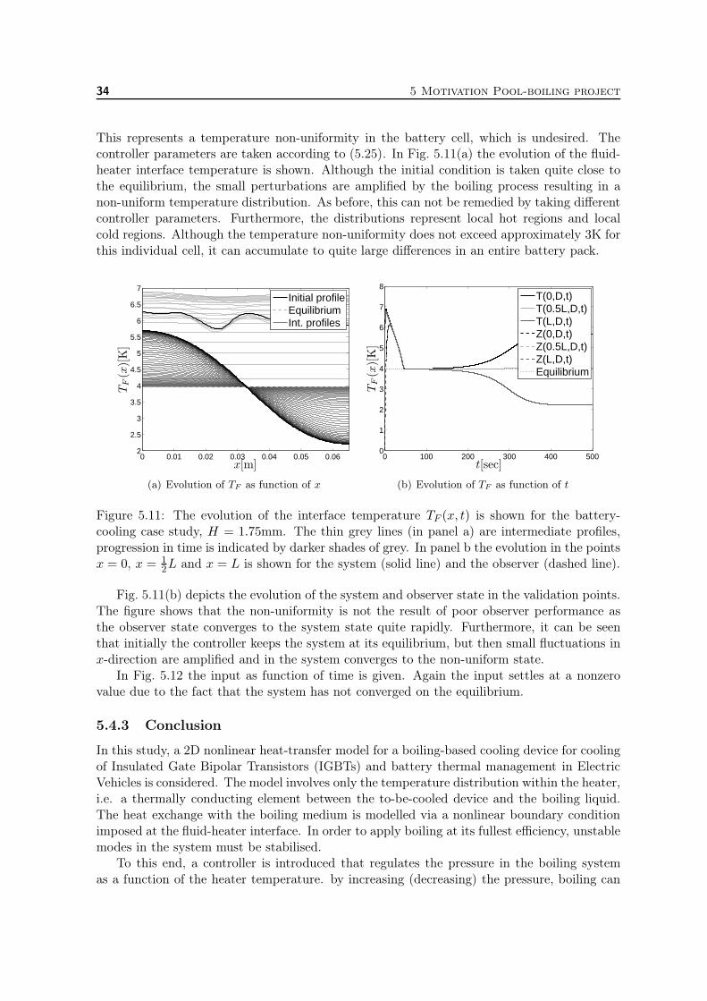
34 5 Motivation Pool-boiling project
This represents a temperature non-uniformity in the battery cell, which is undesired. Thecontroller parameters are taken according to (5.25). In Fig. 5.11(a) the evolution of the fluid-heater interface temperature is shown. Although the initial condition is taken quite close tothe equilibrium, the small perturbations are amplified by the boiling process resulting in anon-uniform temperature distribution. As before, this can not be remedied by taking differentcontroller parameters. Furthermore, the distributions represent local hot regions and localcold regions. Although the temperature non-uniformity does not exceed approximately 3K forthis individual cell, it can accumulate to quite large differences in an entire battery pack.
0 0.01 0.02 0.03 0.04 0.05 0.062
2.5
3
3.5
4
4.5
5
5.5
6
6.5
7Initial profileEquilibriumInt. profiles
x[m]
TF(x)[K]
(a) Evolution of TF as function of x
0 100 200 300 400 5000
1
2
3
4
5
6
7
8T(0,D,t)T(0.5L,D,t)T(L,D,t)Z(0,D,t)Z(0.5L,D,t)Z(L,D,t)Equilibrium
t[sec]
TF(x)[K]
(b) Evolution of TF as function of t
Figure 5.11: The evolution of the interface temperature TF (x, t) is shown for the battery-cooling case study, H = 1.75mm. The thin grey lines (in panel a) are intermediate profiles,progression in time is indicated by darker shades of grey. In panel b the evolution in the pointsx = 0, x = 1
2L and x = L is shown for the system (solid line) and the observer (dashed line).
Fig. 5.11(b) depicts the evolution of the system and observer state in the validation points.The figure shows that the non-uniformity is not the result of poor observer performance asthe observer state converges to the system state quite rapidly. Furthermore, it can be seenthat initially the controller keeps the system at its equilibrium, but then small fluctuations inx-direction are amplified and in the system converges to the non-uniform state.
In Fig. 5.12 the input as function of time is given. Again the input settles at a nonzerovalue due to the fact that the system has not converged on the equilibrium.
5.4.3 Conclusion
In this study, a 2D nonlinear heat-transfer model for a boiling-based cooling device for coolingof Insulated Gate Bipolar Transistors (IGBTs) and battery thermal management in ElectricVehicles is considered. The model involves only the temperature distribution within the heater,i.e. a thermally conducting element between the to-be-cooled device and the boiling liquid.The heat exchange with the boiling medium is modelled via a nonlinear boundary conditionimposed at the fluid-heater interface. In order to apply boiling at its fullest efficiency, unstablemodes in the system must be stabilised.
To this end, a controller is introduced that regulates the pressure in the boiling systemas a function of the heater temperature. by increasing (decreasing) the pressure, boiling can

5.4 Case studies 35
0 100 200 300 400 500−0.5
0
0.5
1u(t)bound
t[sec]
u(t)[W
/cm
2]
Figure 5.12: The input as function of time is shown for the battery-cooling case study, H =1.75mm. The bounds of the input are given by the dashed lines.
be suppressed (stimulated) and as a result, more (less) heat can be extracted from the heaterby the boiling liquid. In this way the boiling system can be kept in the efficient nucleateboiling regime. The entire temperature profile within the heater is estimated by an observerusing only two measurements, both on top of the heater. Previous analyses have shown thatcontrollers based on the dominant modes of the temperature profile within the heater areeffective, see [17]. For this reason, the controller developed for this system is based on thesemodes as well.
The control strategy filters the Chebyshev-Fourier-cosine modes of the temperature profileof the heater. These modes are intimately related to the eigenmodes of the system. There-fore, the dynamics are mainly prescribed by the dominant modes, that is, the lower orderChebyshev-Fourier-cosine modes. The feedback law thus enables control of exactly those rel-evant lower order modes.
The observer is a copy of the nonlinear pool boiling model with an extra term in the bound-ary condition for the fluid heater interface, i.e. the top of the heater, by which convergenceof the observer state on the system state is to be accomplished. This extra term accounts forthe error between observer and system state on the fluid-heater interface.
Local asymptotic stability can be established via the linearised system and observer. Sat-isfactory closed-loop behaviour is obtained by fine-tuning of the control parameters using acharacteristic equation which is derived using the method of separation of variables.
The performance of the control law for stabilisation of the nonlinear system is investigatedin order to establish its value for practical purposes. Relevant issues are the asymptoticstability and evolution of the nonlinear closed-loop system. Simulations are performed for twocase studies: (i) IGBT cooling and (ii) battery thermal management. It turns out that theclosed-loop behaviour of the system is dependent on the system parameters such as height ofthe heater.
The first case study reveals convergence of the evolution of the nonlinear system on theunstable steady state for a wide range of initial states in case H = 20mm. These findings implythat the control loop indeed is capable of robustly stabilising the pool-boiling system for theseparameters. For a thinner heater, H = 8mm, however, convergence of the nonlinear system onan essentially non-uniform state is observed. The final state has a region with temperatures
36 5 Motivation Pool-boiling project
corresponding to nucleate boiling (’cold spots’) and has a region corresponding to film boiling(’hot spots’). This results in local ’hot-spots’ on the IGBT and is highly undesired since itcan lead to failure of the device. In some cases, this phenomenon can be remedied by varyingthe nominal pressure in the boiling chamber. However, for these heater properties the onlymeasure is stabilisation of the nucleate boiling equilibrium. A safety margin needs to be takeninto account for this measure, though, this affects the cooling efficiency negatively.
If boiling is applied to the individual cells in a battery pack, the net evaporation/condensationof the boiling liquid plays a significant role as the volume of the pool is much smaller due tothe closely packed battery cells. Physical considerations suggest that this can in a first ap-proximation be modelled by a rescaled boiling curve. Therefore, thermal management of thesecells, in spite of their low heat generation, still is a challenge, since non-uniform temperaturesand local ’hot spots’ may still occur. The case study reveals that convergence to the unstableuniform transition boiling equilibrium can nonetheless be achieved for H = 3.5mm. For thiscase study, similar as for the IGBT-cooling case study, also convergence to a non-uniformstate is observed for a thinner heater, i.e. H = 1.75mm. This is highly undesired in batterythermal management, as it leads to more rapid battery deterioration.
Nevertheless, both case studies show that the efficiency of boiling-based cooling schemescan be increased by dynamically varying the pressure inside the boiling chamber. This putsforth boiling heat transfer as a promising solution for thermal management issues in electricvehicles. During the design process heater material and dimensions must be chosen carefully,though.
6 Conclusions
In this study several Battery Electric Vehicles (BEVs) and Hybrid Electric Vehicles (HEVs)are examined. The main conclusion concerning BEVs on todays automotive market is thattheir battery can be cooled passively by air. For HEV battery packs cooling is a little bitmore critical as their charge/discharge profiles are more aggressive and more power must besupplied. However, a single-phase liquid cooling scheme suffices in HEV applications.
On the other hand recovering the minimal amount of heat that can be recovered by abattery thermal management system can seriously increase the range per charge of the BEV. Incity driving, average vehicle speeds are low, moreover, heat generation in IGBTs and batteriesis high due to the high frequency of regenerative braking and rapid accelerating of the vehicle.As a result, recovering the waste heat of the IGBTs and (to less extend) the batteries andre-use it to heat the cabin of the vehicle increases the vehicle range significantly. For example,heating power requirements 3 – 4 kW can decrease the range of BEVs in city driving withmore than 50%. Recovering the waste heat of electrical components and using it to heat thecabin thus can help to increase the range of BEVs. At higher speeds, e.g. highway driving,this effect tones down, yet is still significant, as is discussed in Chapter 3.
However, if BEV battery packs are not thermally managed, this can result in reducedrange and lifetime of the batteries and thus the vehicle. In Chapter 4 it is recapitulated thatoperation at increased temperatures of only 10 – 20 K can seriously reduce battery lifetime byseveral hundreds of cycles. Operation of Sony 18650 Li-ion cells at 50◦C, for example, resultedin 50% capacity loss after only 600 cycles and even 70% capacity loss at 55◦ after only 500cycles, which is, compared to the 31% capacity loss after 800 cycles at 25◦C, a massive increaseof degradation at these elevated temperatures. With respect to battery lifetime/deterioration,it thus is necessary to implement better thermal management schemes in EVs.
Furthermore, a thermal management system can increase the degree of temperature uni-formity in the pack, which can increase battery lifetime as well. Since if the cells and modulesin the pack are at different temperatures, each module will be charged/discharged slightlydifferently during each cycle. After several cycles, modules in the pack will become unbal-anced, degrading the pack’s performance. Hence, especially in consideration of cycle life of thebattery pack a thermal management/homogenisation scheme is indispensable as is discussedin Chapter 4.
Moreover, although single phase liquid cooling in HEVs and air cooling in BEVs seems to beable to do the trick in current EVs, development of battery technology continues, introducingthe need for more advanced cooling schemes. The single-phase cooling loops in HEVs requirebulky electrical pumps to circulate the coolant, enhanced cooling methods based on naturalconvection might be interesting, so as to decrease the energy requirements and overall weightof the cooling scheme.
Not only the battery pack is a source of thermal issues in EVs, cooling of chips, or InsulatedGate Bipolar Transistors (IGBTs), is a challenge as well. To overcome overheating of thesehigh power switching devices research on micro-channel flow boiling is conducted. As micro-channel flow boiling and pool boiling have essential similarities, the research of pool-boilingphenomena fits in this respect as well.
37

38 6 Conclusions
The thermal issues discussed above can be solved by application of boiling heat transfer.The key advantages of a boiling-based cooling schemes in EVs are (i) large cooling capacities,(ii) the reduction of weight compared to the weight of a single-phase cooling loop, (iii) tem-perature uniformity of the battery in favour of battery lifespan and (iv) waste heat recoveryfor cabin heating. To prevent the high power switching devices or IGBTs from overheating,a large heat flux per square cm is required. This can be obtained by applying boiling heattransfer to the chips. As the energy density per unit mass of the coolant is much larger thanthat of a single-phase cooling loop, the mass of the required coolant in the cooling designis much lower. Since boiling heat transfer occurs at a constant temperature irrespective ofthe heat flux, thermal management by boiling heat transfer allows for optimal temperaturehomogenisation of the battery. As boiling heat transfer allows for quick and intensive cooling,the removed heat can be released easily and effectively by condensation to any desired surface,for example for cabin heating.
Hence, the project where pool-boiling phenomena are investigated by a pool-boiling modelseems to fit well in the "Range Extender Innovations (REI)" project of the High Tech Auto-motive Systems (HTAS) programme.

Acknowledgements
This research is funded by the HTAS-REI (Range Extender Innovations) project.
39

40 6 Conclusions
Bibliography
[1] S. Al Hallaj and J. Selman, A novel thermal management system for electric vehiclebatteries using phase-change material, Journal of the electrochemical society, 147 (2000),pp. 3231 – 3236.
[2] A. Alrashdan, A. T. Mayyas, and S. Al-Hallaj, Thermo-mechanical behaviorsof the expanded graphite-phase change material matrix used for thermal management ofli-ion battery packs, Journal of Materials Processing Technology, 210 (2010), pp. 174–179.
[3] H. Auracher and W. Marquardt, Experimental studies of boiling mechanisms inall boiling regimes under steady-state and transient conditions, International Journal ofThermal Sciences, 41 (2002), pp. 586–598.
[4] H. Auracher and W. Marquardt, Heat transfer characteristics and mechanismsalong entire boiling curves under steady-state and transient conditions, International Jour-nal of Heat and Fluid Flow, 25 (2004), pp. 223–242.
[5] S. Barnes, F. Fleming, W. Longardner, and A. Rafalovich, Thermal man-agement for HEV valve-regulated lead-acid batteries, in Proceedings of the 12th annualinternational electric vehicle symposium, December 1994, pp. 27 – 37.
[6] K. Bennion and M. Thornton, Integrated vehicle thermal management for advancedvehicle propulsion technologies, in SAE world congress, Detroit, Michigan, USA, April 13– 15, 2010.
[7] G. Berdichevsky, K. Kelty, J. Straubel, and E. Toomre, The tesla roadsterbattery system. Tesla Motors, August 16, 2006.
[8] I. Besselink, P. van Oorschot, and H. Nijmeijer, Design of an efficient, low weightbattery electric vehicle based on a vw lupo 3l, in The 25th world battery, hybrid and fuelcell electric vehicle symposium and exhibition (EVS-25), Shenzhen, China, November 5– 9, 2010.
[9] J. Blum, W. Marquardt, and H. Auracher, Stability of boiling systems, Interna-tional Journal of Heat and Mass Transfer, 39 (1996), pp. 3021–3033.
[10] C. Canuto, M. Hussaini, A. Quarteroni, and T. Zang, Spectral Methods in FluidDynamics, Springer, New York, third ed., 1988.
[11] Y. Chen and J. Evans, Heat transfer phenomena in lithium/polymer-electrolyte batter-ies for electric vehicle application, J. Electrochem. Soc., 140 (1993), pp. 1833 – 1838.
[12] R. Chu, R. Simons, M. Ellsworth, R. Schmidt, and V. Cozzolino, Review ofcooling technologies for computer products, IEEE Transactions on Device and MaterialsReliability, 4 (2004), pp. 568–585.
[13] V. Dhir, Boiling heat transfer, Annu. Rev. Fluid Mech., 30 (1998), pp. 365–401.
41
42 Bibliography
[14] C. Dustmann, Advances in zebra batteries, Journal of Power Sources, 127 (2004), pp. 85– 92.
[15] S. Garimella and T. Harirchian, Boiling heat transfer and flow regimes in mi-crochannels – a comprehensive understanding, in 15th International Workshop on Ther-mal Investigation of ICs and Systems (Therminic) 2009, Leuven, Belgium, October 7 –9, 2009, pp. 101– 112.
[16] R. van Gils, M. Speetjens, and H. Nijmeijer, Feedback stabilisation of a one-dimensional nonlinear pool-boiling system, International Journal of Heat and Mass Trans-fer, 53 (2010), pp. 2393–2403.
[17] R. van Gils, M. Speetjens, and H. Nijmeijer, Feedback stabilisation of two-dimensional non-uniform pool-boiling states, in Advanced Computational Methods andExperiments in Heat Transfer XI, B. Sundén, U. Mander, and C. Brebbia, eds., Tallin,Estonia, July 14 – 16, 2010, WIT Press, pp. 215 – 226.
[18] R. van Gils, M. Speetjens, and H. Nijmeijer, Feedback stabilization of transitionboiling states, in Proceedings of the 12th IEEE Intersociety Conference on Thermal andThermomechanical Phenomena in Electric Systems (ITherm 2010), no. 044, Bally’s, LasVegas, Nevada, USA, June 2 – 5, 2010.
[19] R. van Gils, M. Speetjens, and H. Nijmeijer, Boiling heat transfer in battery electricvehicles, in EEVC 2011, Brussels, Belgium, October 26 – 28, 2011.
[20] R. van Gils, M. Speetjens, and H. Nijmeijer, Feedback stabilisation of a two-dimensional pool-boiling system by modal control, Int. J. of Thermal Sciences, (2012).submitted for publication.
[21] L. Guzzella and A. Sciarretta, Vehicle Propulsion Systems, Springer, Berlin, sec-ond ed., 2007.
[22] E. Hansen, L. Wilhelm, N. Karditsas, I. Menjak, D. Corrigan, S. Dhar, and
S. Ovshinsky, Full system nickel-metal hyrdide battery packs for hybrid electric vehicleapplications, in Battery conference on applications and advances, 2002. The seventeenthannual, Long Beach, CA , USA, 15 – 18 Jan. 2002, pp. 253 – 260.
[23] T. Heckenberg, Li-ion battery cooling: more than just another cooling task, internalreport, BEHR, 2009.
[24] R. Hohl, J. Blum, M. Buchholz, T. Lüttich, H. Auracher, and W. Mar-
quardt, Model-based experimental analysis of pool boiling heat transfer with controlledwall temperature transients, International Journal of Heat and Mass Transfer, 44 (2001),pp. 2225–2238.
[25] J. Hsu, R. Staunton, and M. Starke, Barriers to the application of high-temperaturecoolants in hybrid electric vehicles, Technical report ORNL/TM-2006/514, Oak RidgeNational Laboratory, 2006.
[26] I. Husain, Electric and hybrid vehicles, design fundamentals, CRC press, first ed., 2003.
Bibliography 43
[27] S. G. Kandlikar, Critical heat flux in subcooled fow boiling – an assesment of currentunderstanding and future directions for research, Multiphase Sci Technol., 13 (2001),pp. 207 – 232.
[28] S. G. Kandlikar, Heat transfer mechanisms during flow boiling in microchannels,ASME J. Heat Transfer, 126 (2004), pp. 8 – 16.
[29] S. G. Kandlikar, Similarities and differences between flow boiling in microchannels andpool boiling, in Proceedings of the second micro and nano flows conference, West London,2009.
[30] P. A. Kew and K. Cornwell, Correlations for the prediction of boiling heat transferin small-diameter channels, Applied Thermal Engineering, 17 (1997), pp. 705–715.
[31] V. Khanna, The insulated gate bipolar transistor: IGBT theory and design, Wiley,first ed., 2003.
[32] S. Khateeb, M. Farid, J. Selman, and S. Al-Hallaj, Design and simulation ofa lithium-ion battery with a phase change material thermal management system for anelectric scooter, Journal of Power Sources, 128 (2003), pp. 292 – 307.
[33] S. A. Khateeb, S. Amiruddin, M. Farid, J. R. Selman, and S. Al-Hallaj,Thermal management of li-ion battery with phase change material for electric scooters:experimental validation, Journal of Power Sources, 142 (2005), pp. 345–353.
[34] E. Kreyszig, Advanced Engineering Mathematics, Wiley, New York, eighth ed., 1999.
[35] P. Kroner, Thermal comfort in the vehicle. new vehicle designs require new a/c solu-tions, internal report, BEHR, 2009.
[36] J. Larminie and J. Lowry, Electric vehicle technology explained, Wiley, first ed., 2003.
[37] B. McKinney, G. Wierschem, and E. Nrotek, Thermal management of lead-acidbatteries for electric vehicles, in Batteries for electric vechicle-research development andtesting conference, Detroit, Michigan, USA, February 28, 2003.
[38] A. Mills and S. Al-Hallaj, Simulation of passive thermal management system forlithium-ion battery packs, Journal of Power Sources, 141 (2005), pp. 307–315.
[39] I. Mudawar, Assessment of high-heat-flux thermal management schemes, IEEE Trans-actions on Components and Packaging Technologies, 24 (2001), pp. 122–141.
[40] P. van Oorschot, Battery test: Thundersky lfp90aha, tech. report, Eindhoven Uni-versity of Technology, Department of Mechanical Engineering, Dynamics and ControlGroup, 2010.
[41] P. van Oorschot, I. J. M. Besselink, and H. Nijmijer, Realization of an ev researchplatform and its range estimation, -, (2011), pp. xx – xx. (In preparation).
[42] P. van Oorschot and R. Vos, Electric vehicle test: Vw golf variant ece, Tech. ReportDC 2010.036, Eindhoven University of Technology, Department of Mechanical Engineer-ing, Dynamics and Control Group, 2010.
44 Bibliography
[43] H. Van Ouwerkerk, Burnout in pool boiling the stability of boiling mechanisms, Inter-national Journal of Heat and Mass Transfer, 15 (1972), pp. 25–34.
[44] A. Pal, Y. Joshi, M. Beitelmal, C. Patel, and T. Wenger, Design and per-formance evaluation of a compact thermosyphon, in Thermes, Sante Fe, USA, jan 13-162002, pp. 251 –260.
[45] A. Pesaran, Battery thermal management in EV’s and HEV’s: Issues and solutions, inProceedings of the Advanced Automotive Battery Conference, Las Vegas, Nevada, USA,February 6 – 8, 2001.
[46] A. Pesaran, Current and future needs in electric drive vehicle batteries, in Proceedings ofthe 14th international heat transfer conference, IHTC14, Washington DC, USA, August8 – 13, 2010.
[47] A. Pesaran, T. Markel, H. Tataria, and D. Howell, Battery requirements forplug-in hybrid electric vehicles – analysis and rationale, in 23rd International electricvehicle symposium (EVS-23), Anaheim, California, USA, December 2 – 5, 2007.
[48] A. Pesaran, A. Vlahinos, and S. Burch, Thermal performance of EV and HEVbattery modules and packs, in Proceedings of the 14th international electric vehicle sym-posium, Orlando, Florida, December 15 – 17, 1997.
[49] A. Pesaran, A. Vlahinos, and T. Stuart, Cooling and preheating of batteries inhybrid electric vehicles, in 6th ASMR-JSME Thermal Engineering Conference, Hawaii,USA, March 16 – 20, 2003.
[50] P. Ramadass, B. Haran, R. White, and B. Popov, Capacity fade of sony 18650cells cycled at elevated temperatures: Part ii. capacity fade analysis, Journal of PowerSources, 112 (2002), pp. 614–620.
[51] M. Speetjens, Steady-state behavior of a three-dimensional pool-boiling system, J. Elec-tron. Packag., 130 (2008), pp. 041102–7.
[52] M. Speetjens, A. Reusken, S. Maier-Paape, and W. Marquardt, Stability analy-sis of two-dimensional pool-boiling systems, SIAM Journal of Applied Dynamical Systems,7 (2008), pp. 933–961.
[53] M. Speetjens, A. Reusken, and W. Marquardt, Steady-state solutions in a nonlin-ear pool boiling model, Communications in Nonlinear Science and Numerical Simulation,13 (2006), pp. 1475–1494.
[54] M. Speetjens, A. Reusken, and W. Marquardt, Steady-state solutions in a three-dimensional nonlinear pool-boiling heat-transfer model, Communications in Nonlinear Sci-ence and Numerical Simulation, 13 (2006), pp. 1518–1537.
[55] J. R. Thome, Boiling in microchannels: a review of experiment and theory, InternationalJournal of Heat and Fluid Flow, 25 (2004), pp. 128–139.
[56] Website, http://thinkev.com/, visited in August 2010. Official website Think City Elec-tric Vehicle.
Bibliography 45
[57] Website, http://www.chevrolet.com/pages/open/default/future/volt.do, visited in Au-gust 2010. Official Chevrolet Volt website.
[58] Website, http://www.ener1.com/?q=content/enerdel-main, visited in August 2010. Of-ficial website of Enerdel.
[59] Website, http://www.greencarcongress.com/2009/09/garimella-20090923.html, visitedin August 2010. Green car congress website.
[60] Website, http://www.nissanusa.com/leaf-electric-car, visited in August 2010. OfficialU.S. Nissan Leaf website.
[61] M.-S. Wu, K. H. Liu, Y.-Y. Wang, and C.-C. Wan, Heat dissipation design forlithium-ion batteries, Journal of Power Sources, 109 (2002), pp. 160–166.
[62] M. Zolot, K. Kelly, M. Keyser, M. Mihalic, and A. Pesaran, Thermal evalu-ation of the honda insight battery pack, in the 36th intersociety energy conversion engi-neering conference (IECEC’01), Savannah, Georgia, USA, July 29 - August 2, 2001.
[63] M. Zolot, A. Pesaran, and M. Mihalic, Thermal evaluation of toyota prius batterypack. National Renewable Energy Laboratory, 2002.

46 Bibliography

A Paper EEVC
In the following the paper that has been published in the proceedings of the European ElectricVehicle Conference (EEVC), [19], is given.
47

EEVCBrussels, Belgium, October 26-28, 2011
Boiling Heat Transfer in Battery Electric Vehicles
Rob van Gils1,∗, Michel Speetjens2, Henk Nijmeijer11Eindhoven University of Technology, Department of Mechanical Engineering, Dynamics and Control group2Eindhoven University of Technology, Department of Mechanical Engineering, Energy Technology group
∗Corresponding author, P.O Box 513, WH -1.144, 5600 MB, Eindhoven,[email protected]
Abstract
In this paper the feedback stabilisation of a boiling-basedcooling scheme is discussed. Application ofsuch cooling schemes in practical setups is greatly limitedby the formation of a thermally insulatingvapour film on the to-be-cooled device, called burn-out. In this study a first step is made, to checkthe viability of such cooling systems, already used in high performance electronics, applied to ElectricVehicles (EVs). It can be used for instance for the cooling ofhigh heat flux transistors and for thethermal homogenisation of battery packs. Thereto, the unstable transition to burn-out is stabilised bycontrolling the pressure inside the boiling chamber, with which boiling (and thus creation of the thermallyinsulating vapour film) can be stimulated or suppressed. Thefeedback law used to do this is basedon the dominant modes of the temperature field of the thermally conducting element, i.e. the heater,between the device and the boiling liquid. As not all states used in this feedback law can be measured,an observer or ”state-estimator” must be implemented in thecontrol strategy. The observer is a copy ofthe nonlinear boiling model with an additional term to assure convergence of observer to system state.Simulations are performed to demonstrate controller efficiency on the nonlinear cooling device. This putsforth the boiling-based cooling scheme as viable for application in EVs, enabling increased cooling andthermal-homogenisation capacities compared to conventional thermal management methods. The nextstep should be experiments to proof the principle on batterycells/packs and high heat flux transistors.
Keywords: BEV, Battery thermal management, Cooling, boiling, numerical simulation
1 Introduction
During fast acceleration and regenerative brak-ing in electric vehicles (EVs), the high-powerswitching devices, that switch large amounts ofpower from the battery pack to the electricalcoils of the electric motors, produce significantamounts of heat. To prevent these so-called insu-lated gate bipolar transistors (IGBTs) from over-heating during these actions, boiling heat transferis the pre-eminent choice as the cooling mech-anism. Boiling heat transfer namely allows forquickandintensivecooling. Moreover, the evap-orated fluid can be easily transported throughoutthe vehicle, and the removed heat can be releasedto any desired surface via condensation. In thisway, the removed heat can be used, for instance
to heat the vehicle cabin, decreasing the auxil-iary power requirements. In addition, due to nat-ural convection, no (large) pumps are required tocirculate the fluids. Thus thermal managementbased on boiling heat transfer can significantlyincrease the range per charge of Battery ElectricVehicles (BEVs) [1], which is currently consid-ered to be their main drawback, [2].Boiling heat transfer can also be applied as bat-tery thermal management system. Operation atelevated temperatures can seriously acceleratebattery deterioration, see [3]. While operationat lowered temperatures can seriously decreasethe efficiency of the battery, see [1]. Further-more, due to the passive working principle, boil-ing heat transfer can also be applied when the caris turned off, e.g. when the car is parked in thesun. Another important parameter with respect
EEVC European Electric Vehicle Congress 1

to the battery lifespan is the temperature unifor-mity of the battery, see [4]. Hence, especially inconsideration of cycle life of the battery pack, athermal management/homogenisation scheme isindispensable. Boiling heat transfer allows forthermal homogenisation very effectively as it, ir-respective of heat fluxes, happens at fixed tem-peratures for given pressure, see [5].However, full exploitation of boiling heat trans-fer for thermal management is severely limitedby the risk of ’burn-out’, i.e. the sudden forma-tion of a vapour blanket on the heating device thatleads to a catastrophic temperature jump and, inconsequence, an abrupt collapse of the coolingand homogenisation capacity [6]. Insight intothe complex boiling dynamics underlying “burn-out” and into ways to actively control it, is im-perative to overcome this hazard.Pool boiling may serve as physical representa-tion for cooling applications based on boilingheat transfer. Such systems consist of a heatersubmerged in a pool of boiling liquid. This isdepicted in Fig.1, the to-be-cooled device sup-plies heat to the bottom wall of the heater, whichcorresponds with a thermally conducting elementbetween the actual heat source (e.g. a batterycell) and the coolant at the top wall of the heater.The boiling liquid extracts heat from the heaterand releases thermal energy through the escap-ing vapour. The vapour turns into liquid againin a condenser, releasing the heat taken up, andflows back towards the boiling liquid.
Figure 1: Schematic representation of a pool-boilingsystem.
Pool boiling is characterised by three boilingregimes through which the system progresseswith increasing temperature on the fluid-heaterinterface: nucleate, transition and film boiling[7]. Nucleate boiling is, as opposed to film boil-ing, an efficient and safe mode of heat transferand is the desired boiling mode in most practicalapplications. Nucleate boiling transits into filmboiling upon exceeding the so-called critical heatflux (CHF) through the intermediate state of tran-sition boiling. This transition is highly unstableand causes a sharpincreasein temperature anddecreasein heat flux. This is the result of the sud-den formation of a thermally-insulating vapourfilm on the fluid-heater interface [6]. Transition,thus, leads to the collapse of the cooling and ho-mogenisation capacity and must be avoided inpractical thermal management systems [7].
Hence, utilising boiling heat transfer for coolingentails a trade-off between efficiency (close prox-imity to CHF) and safe operation (certain dis-tance from CHF). Current cooling schemes re-quire a relatively large safety margin due to twokey limitations: (i) high uncertainty in predictingCHF and system dynamics; (ii) the inability toactively respond to fluctuating cooling demandsdue to the passive working principle [8]. Ro-bust control strategies that safely facilitate boil-ing heat transfer close to CHF under dynamic op-erating conditions offer a promising solution, yettheir realisation poses a formidable challenge.As a result, to date theoretical studies for poolboiling applications are scarce. There is a largedata-base on boiling experiments, though. How-ever, the CHF depends, next to the fluid-heatercombination, on numerous other variables, suchas surface roughness and system pressure. Con-sequently, experimental results can only be usedin a very limited range of boiling applications,see e.g. [6, 9]. Theoretical pool boiling in-vestigations are presented in [10] where a one-dimensional (1D) system is stabilised by way oflinearisation of the boiling curve around the ho-mogeneous transition state. In [11] a more realis-tic pool boiling model is formulated which leanson the phenomenological connection betweenthe local boiling mode and the interface temper-ature and describes the system dynamics entirelyin terms of the temperature distribution withinthe heater. In [12, 13] the two-dimensional (2D)nonlinear heater-only model is analysed for equi-libria and stability properties. Successful stabili-sation of the one-dimensional (1D) simplificationof this model has been achieved in [14] by regula-tion of the heat supply via a linear state feedbackbased on the internal temperature profile. Mostrecent investigations of stabilisation of unstablesteady states of the original 2D model are pre-sented in [15, 16].Key to the proposed control strategy is the ex-pression of the heater’s temperature profile byChebyshev and Fourier polynomials, which areintimately related to the physical eigenmodes ofthe 2D system. The smoothness of the temper-ature field within the heater ensures exponen-tial convergence of the Chebyshev-Fourier spec-trum and, consequently, accurate representationof its eigenmodes by lower-order Chebyshev andFourier polynomials. This has the important im-plication that the system dynamics can be regu-lated on the basis of a few lower-order Fourier-Chebyshev modes of the temperature field.This study aims to test this 2D modal control lawfor the purpose of thermal management in EVsby way of a performance analysis in an idealisedsystem as first step towards realisation of a prac-tical setup. Thereto, the dynamical behaviour ofthe system introduced in [16] is considered forrealistic values of the physical parameters. Thecontrol law represents the dynamical variation ofthe system pressure, with which the onset of filmboiling is to be prevented. The simulations repre-sent two thermal issues in EVs, being (i) IGBT-cooling and (ii) thermal homogenisation of thebattery pack. These simulations are a first steptowards realisation of a practical setup.
EEVC European Electric Vehicle Congress 2
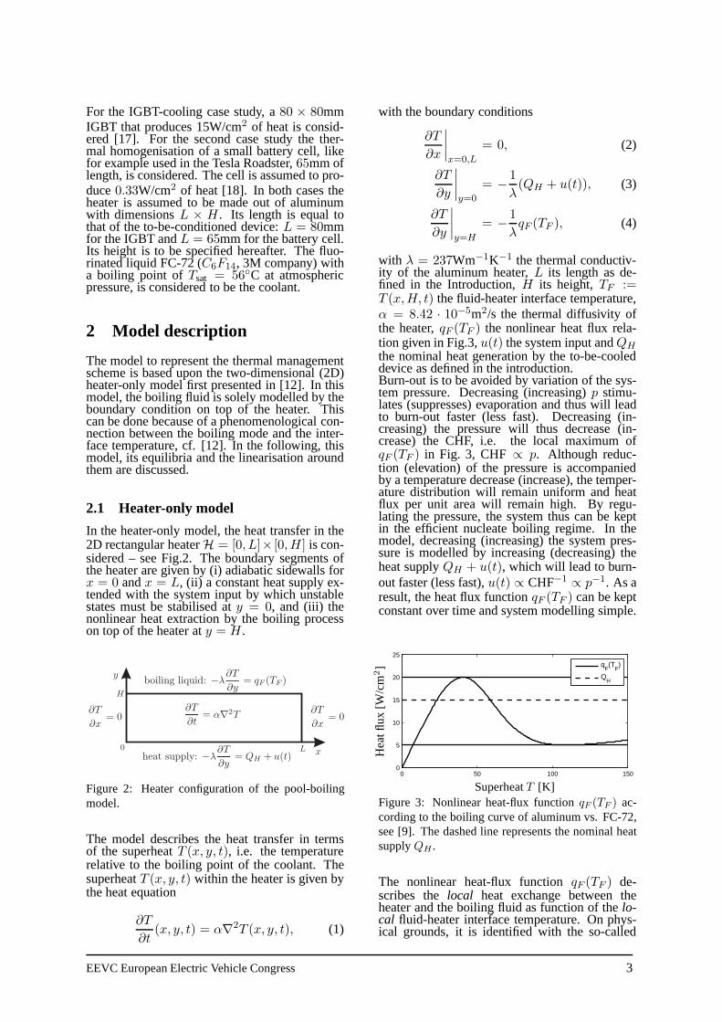
For the IGBT-cooling case study, a80 × 80mmIGBT that produces 15W/cm2 of heat is consid-ered [17]. For the second case study the ther-mal homogenisation of a small battery cell, likefor example used in the Tesla Roadster,65mm oflength, is considered. The cell is assumed to pro-duce0.33W/cm2 of heat [18]. In both cases theheater is assumed to be made out of aluminumwith dimensionsL × H. Its length is equal tothat of the to-be-conditioned device:L = 80mmfor the IGBT andL = 65mm for the battery cell.Its height is to be specified hereafter. The fluo-rinated liquid FC-72 (C6F14, 3M company) witha boiling point ofTsat = 56◦C at atmosphericpressure, is considered to be the coolant.
2 Model description
The model to represent the thermal managementscheme is based upon the two-dimensional (2D)heater-only model first presented in [12]. In thismodel, the boiling fluid is solely modelled by theboundary condition on top of the heater. Thiscan be done because of a phenomenological con-nection between the boiling mode and the inter-face temperature, cf. [12]. In the following, thismodel, its equilibria and the linearisation aroundthem are discussed.
2.1 Heater-only model
In the heater-only model, the heat transfer in the2D rectangular heaterH = [0, L]× [0,H] is con-sidered – see Fig.2. The boundary segments ofthe heater are given by (i) adiabatic sidewalls forx = 0 andx = L, (ii) a constant heat supply ex-tended with the system input by which unstablestates must be stabilised aty = 0, and (iii) thenonlinear heat extraction by the boiling processon top of the heater aty = H.
Figure 2: Heater configuration of the pool-boilingmodel.
The model describes the heat transfer in termsof the superheatT (x, y, t), i.e. the temperaturerelative to the boiling point of the coolant. ThesuperheatT (x, y, t) within the heater is given bythe heat equation
∂T
∂t(x, y, t) = α∇2T (x, y, t), (1)
with the boundary conditions
∂T
∂x
∣∣∣∣x=0,L
= 0, (2)
∂T
∂y
∣∣∣∣y=0
= − 1
λ(QH + u(t)), (3)
∂T
∂y
∣∣∣∣y=H
= − 1
λqF (TF ), (4)
with λ = 237Wm−1K−1 the thermal conductiv-ity of the aluminum heater,L its length as de-fined in the Introduction,H its height,TF :=T (x,H, t) the fluid-heater interface temperature,α = 8.42 · 10−5m2/s the thermal diffusivity ofthe heater,qF (TF ) the nonlinear heat flux rela-tion given in Fig.3,u(t) the system input andQH
the nominal heat generation by the to-be-cooleddevice as defined in the introduction.Burn-out is to be avoided by variation of the sys-tem pressure. Decreasing (increasing)p stimu-lates (suppresses) evaporation and thus will leadto burn-out faster (less fast). Decreasing (in-creasing) the pressure will thus decrease (in-crease) the CHF, i.e. the local maximum ofqF (TF ) in Fig. 3, CHF ∝ p. Although reduc-tion (elevation) of the pressure is accompaniedby a temperature decrease (increase), the temper-ature distribution will remain uniform and heatflux per unit area will remain high. By regu-lating the pressure, the system thus can be keptin the efficient nucleate boiling regime. In themodel, decreasing (increasing) the system pres-sure is modelled by increasing (decreasing) theheat supplyQH + u(t), which will lead to burn-out faster (less fast),u(t) ∝ CHF−1 ∝ p−1. As aresult, the heat flux functionqF (TF ) can be keptconstant over time and system modelling simple.
0 50 100 1500
5
10
15
20
25
qF(T
F)
QH
SuperheatT [K]
Hea
tflu
x[W
/cm2
]
Figure 3: Nonlinear heat-flux functionqF (TF ) ac-cording to the boiling curve of aluminum vs. FC-72,see [9]. The dashed line represents the nominal heatsupplyQH .
The nonlinear heat-flux functionqF (TF ) de-scribes thelocal heat exchange between theheater and the boiling fluid as function of thelo-cal fluid-heater interface temperature. On phys-ical grounds, it is identified with the so-called
EEVC European Electric Vehicle Congress 3
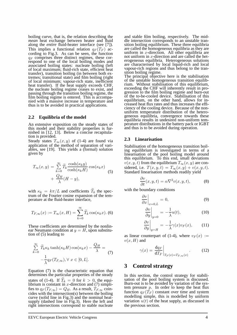
boiling curve, that is, the relation describing themean heat exchange between heater and fluidalong theentire fluid-heater interface (see [7]).This implies a functional relationqF (TF ) ac-cording to Fig.3. As can be seen, the functionqF comprises three distinct regimes, these cor-respond to one of the local boiling modes andassociated boiling states: nucleate boiling (leftof local maximum; fluid-rich state, efficient heattransfer), transition boiling (in between both ex-tremes; transitional state) and film boiling (rightof local minimum; vapour-rich state, inefficientheat transfer). If the heat supply exceeds CHF,the nucleate boiling regime ceases to exist, andpassing through the transition boiling regime, thefilm boiling regime is entered. This is accompa-nied with a massive increase in temperature andthus is to be avoided in practical applications.
2.2 Equilibria of the model
An extensive exposition on the steady states ofthis model and their stability properties is fur-nished in [12, 13]. Below a concise recapitula-tion is provided.Steady statesT∞(x, y) of (1-4) are found viaapplication of the method of separation of vari-ables, see [19]. This yields a (formal) solutiongiven by
T∞(x, y) =∞∑k=0
Tk
cosh(κky)
cosh(κkH)cos(κkx)
+QH
λ(H − y),
(5)
with κk = kπ/L and coefficientsTk the spec-trum of the Fourier cosine expansion of the tem-perature at the fluid-heater interface,
TF,∞(x) := T∞(x,H) =
∞∑
k=0
Tk cos(κkx). (6)
These coefficients are determined by the nonlin-ear Neumann condition aty = H, upon substitu-tion of (5) leading to
∞∑k=0
Tkκk tanh(κkH) cos(κkx)−QH
λ=
− 1
λqF (TF,∞),∀ x ∈ [0, L].
(7)
Equation (7) is the characteristic equation thatdetermines the particular properties of the steadystates of (1-4). IfTk = 0 for k > 0, the equi-librium is constant inx-direction and (7) simpli-fies toqF (TF,∞) = QH . As a result,TF,∞ coin-cides with the intersection(s) between the boilingcurve (solid line in Fig.3) and the nominal heat-supply (dashed line in Fig.3). Here the left andright intersections correspond to stable nucleate
and stable film boiling, respectively. The mid-dle intersection corresponds to an unstable tran-sition boiling equilibrium. These three equilibriaare called the homogeneous equilibria as they areuniform in x-direction. All other equilibria arenot uniform inx-direction and are called the het-erogeneous equilibria. Heterogeneous solutionsare characterised by local liquid-rich and localvapour-rich regions and thus belong to the tran-sition boiling regime.The principal objective here is the stabilisationof the unstable homogeneous transition equilib-rium. Without stabilisation of this equilibrium,exceeding the CHF will inherently result in pro-gression to the film boiling regime and burn-outof the to-be-cooled device. Stabilisation of thisequilibrium, on the other hand, allows for in-creased heat flux rates and thus increases the effi-ciency of the cooling device. Because of the non-uniform temperature distribution of the hetero-geneous equilibria, convergence towards theseequilibria results in undesired non-uniform tem-perature distributions in the battery pack or IGBTand thus is to be avoided during operation.
2.3 Linearisation
Stabilisation of the homogeneous transition boil-ing equilibrium is investigated in terms of alinearisation of the pool boiling model aroundthis equilibrium. To this end, small deviationsv(x, y, t) from the equilibriumT∞(x, y) are con-sidered, i.e.T (x, y, t) = T∞(x, y) + v(x, y, t).Standard linearisation methods readily yield
∂v
∂t(x, y, t) = α∇2v(x, y, t), (8)
with the boundary conditions
∂v
∂x
∣∣∣∣x=0,L
= 0, (9)
∂v
∂y
∣∣∣∣y=0
= − 1
λu(t), (10)
∂v
∂y
∣∣∣∣y=H
= − 1
λγ(x)vF (x), (11)
as linear counterpart of (1-4), wherevF (x) :=v(x,H) and
γ(x) =dqFdTF
∣∣∣∣TF (x)=TF,∞(x)
. (12)
3 Control strategy
In this section, the control strategy for stabili-sation of the pool boiling system is discussed.Burn-out is to be avoided by variation of the sys-tem pressurep. In order to keep the heat fluxfunction qF (TF ) constant over time and systemmodelling simple, this is modelled by uniformvariationu(t) of the heat supply, as discussed inthe previous section.
EEVC European Electric Vehicle Congress 4
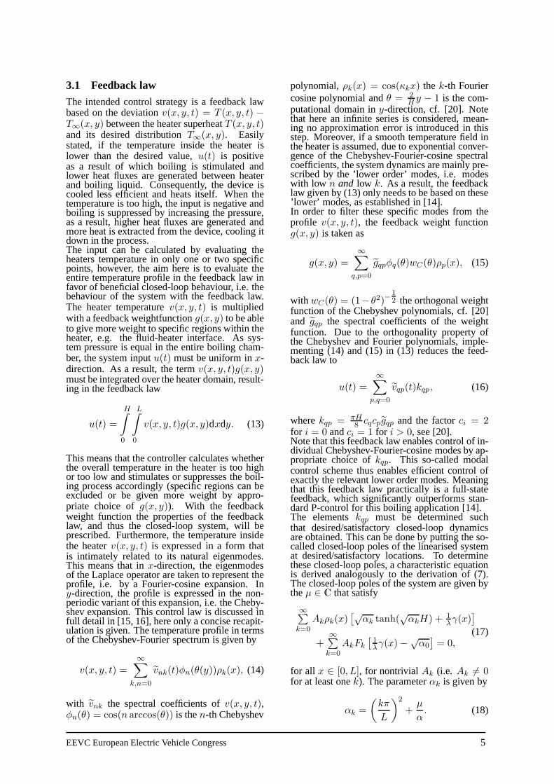
3.1 Feedback law
The intended control strategy is a feedback lawbased on the deviationv(x, y, t) = T (x, y, t) −T∞(x, y) between the heater superheatT (x, y, t)and its desired distributionT∞(x, y). Easilystated, if the temperature inside the heater islower than the desired value,u(t) is positiveas a result of which boiling is stimulated andlower heat fluxes are generated between heaterand boiling liquid. Consequently, the device iscooled less efficient and heats itself. When thetemperature is too high, the input is negative andboiling is suppressed by increasing the pressure,as a result, higher heat fluxes are generated andmore heat is extracted from the device, cooling itdown in the process.The input can be calculated by evaluating theheaters temperature in only one or two specificpoints, however, the aim here is to evaluate theentire temperature profile in the feedback law infavor of beneficial closed-loop behaviour, i.e. thebehaviour of the system with the feedback law.The heater temperaturev(x, y, t) is multipliedwith a feedback weightfunctiong(x, y) to be ableto give more weight to specific regions within theheater, e.g. the fluid-heater interface. As sys-tem pressure is equal in the entire boiling cham-ber, the system inputu(t) must be uniform inx-direction. As a result, the termv(x, y, t)g(x, y)must be integrated over the heater domain, result-ing in the feedback law
u(t) =
H∫
0
L∫
0
v(x, y, t)g(x, y)dxdy. (13)
This means that the controller calculates whetherthe overall temperature in the heater is too highor too low and stimulates or suppresses the boil-ing process accordingly (specific regions can beexcluded or be given more weight by appro-priate choice ofg(x, y)). With the feedbackweight function the properties of the feedbacklaw, and thus the closed-loop system, will beprescribed. Furthermore, the temperature insidethe heaterv(x, y, t) is expressed in a form thatis intimately related to its natural eigenmodes.This means that inx-direction, the eigenmodesof the Laplace operator are taken to represent theprofile, i.e. by a Fourier-cosine expansion. Iny-direction, the profile is expressed in the non-periodic variant of this expansion, i.e. the Cheby-shev expansion. This control law is discussed infull detail in [15, 16], here only a concise recapit-ulation is given. The temperature profile in termsof the Chebyshev-Fourier spectrum is given by
v(x, y, t) =∞∑
k,n=0
vnk(t)φn(θ(y))ρk(x), (14)
with vnk the spectral coefficients ofv(x, y, t),φn(θ) = cos(n arccos(θ)) is then-th Chebyshev
polynomial,ρk(x) = cos(κkx) the k-th Fouriercosine polynomial andθ = 2
Hy − 1 is the com-
putational domain iny-direction, cf. [20]. Notethat here an infinite series is considered, mean-ing no approximation error is introduced in thisstep. Moreover, if a smooth temperature field inthe heater is assumed, due to exponential conver-gence of the Chebyshev-Fourier-cosine spectralcoefficients, the system dynamics are mainly pre-scribed by the ’lower order’ modes, i.e. modeswith low n and low k. As a result, the feedbacklaw given by (13) only needs to be based on these’lower’ modes, as established in [14].In order to filter these specific modes from theprofile v(x, y, t), the feedback weight functiong(x, y) is taken as
g(x, y) =∞∑
q,p=0
gqpφq(θ)wC(θ)ρp(x), (15)
with wC(θ) = (1− θ2)−12 the orthogonal weight
function of the Chebyshev polynomials, cf. [20]and gqp the spectral coefficients of the weightfunction. Due to the orthogonality property ofthe Chebyshev and Fourier polynomials, imple-menting (14) and (15) in (13) reduces the feed-back law to
u(t) =∞∑
p,q=0
vqp(t)kqp, (16)
wherekqp = πH8 cqcpgqp and the factorci = 2
for i = 0 andci = 1 for i > 0, see [20].Note that this feedback law enables control of in-dividual Chebyshev-Fourier-cosine modes by ap-propriate choice ofkqp. This so-called modalcontrol scheme thus enables efficient control ofexactly the relevant lower order modes. Meaningthat this feedback law practically is a full-statefeedback, which significantly outperforms stan-dard P-control for this boiling application [14].The elementskqp must be determined suchthat desired/satisfactory closed-loop dynamicsare obtained. This can be done by putting the so-called closed-loop poles of the linearised systemat desired/satisfactory locations. To determinethese closed-loop poles, a characteristic equationis derived analogously to the derivation of (7).The closed-loop poles of the system are given bytheµ ∈ C that satisfy
∞∑k=0
Akρk(x)[√
αk tanh(√αkH) + 1
λγ(x)
]
+∞∑k=0
AkFk
[1λγ(x)−√
α0
]= 0,
(17)
for all x ∈ [0, L], for nontrivialAk (i.e. Ak 6= 0for at least onek). The parameterαk is given by
αk =
(kπ
L
)2
+µ
α. (18)
EEVC European Electric Vehicle Congress 5
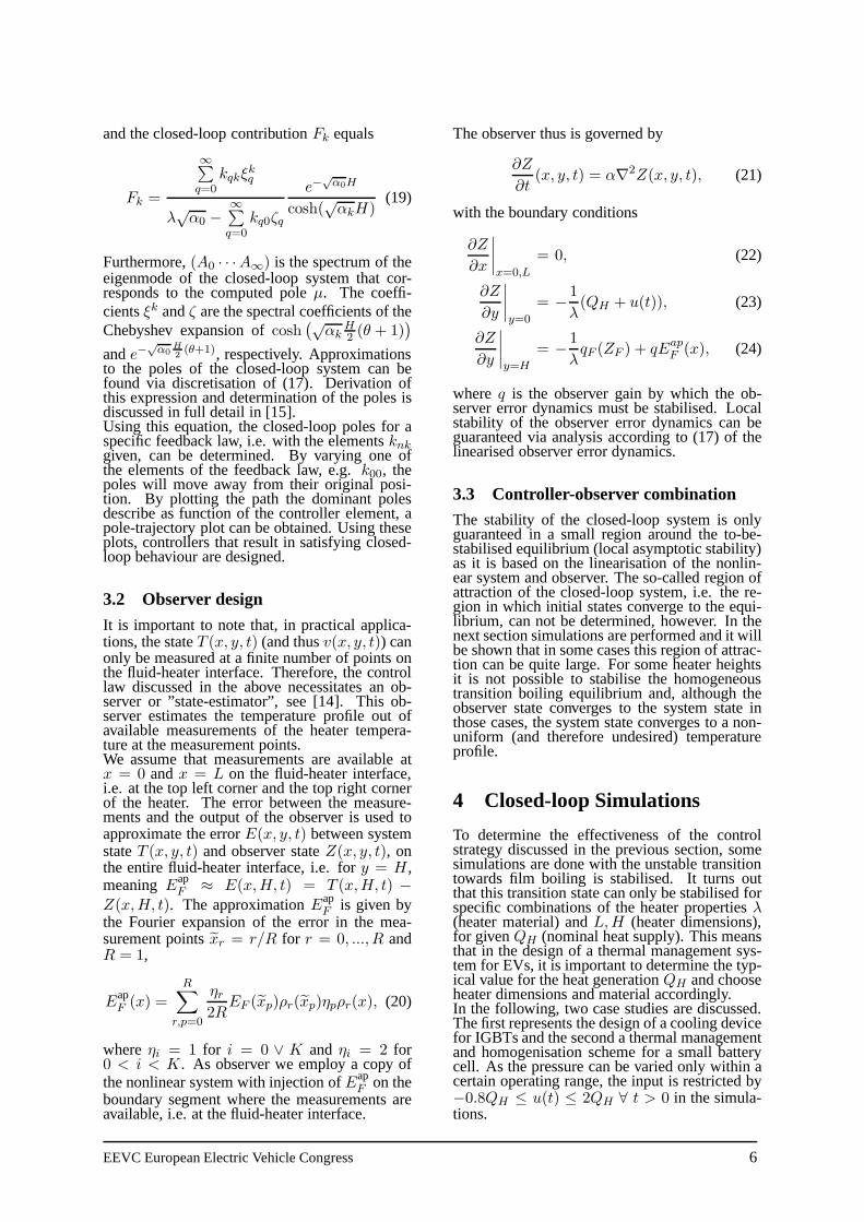
and the closed-loop contributionFk equals
Fk =
∞∑q=0
kqkξkq
λ√α0 −
∞∑q=0
kq0ζq
e−√α0H
cosh(√αkH)
(19)
Furthermore,(A0 · · ·A∞) is the spectrum of theeigenmode of the closed-loop system that cor-responds to the computed poleµ. The coeffi-cientsξk andζ are the spectral coefficients of theChebyshev expansion ofcosh
(√αk
H2 (θ + 1)
)
ande−√α0
H2(θ+1), respectively. Approximations
to the poles of the closed-loop system can befound via discretisation of (17). Derivation ofthis expression and determination of the poles isdiscussed in full detail in [15].Using this equation, the closed-loop poles for aspecific feedback law, i.e. with the elementsknkgiven, can be determined. By varying one ofthe elements of the feedback law, e.g.k00, thepoles will move away from their original posi-tion. By plotting the path the dominant polesdescribe as function of the controller element, apole-trajectory plot can be obtained. Using theseplots, controllers that result in satisfying closed-loop behaviour are designed.
3.2 Observer design
It is important to note that, in practical applica-tions, the stateT (x, y, t) (and thusv(x, y, t)) canonly be measured at a finite number of points onthe fluid-heater interface. Therefore, the controllaw discussed in the above necessitates an ob-server or ”state-estimator”, see [14]. This ob-server estimates the temperature profile out ofavailable measurements of the heater tempera-ture at the measurement points.We assume that measurements are available atx = 0 andx = L on the fluid-heater interface,i.e. at the top left corner and the top right cornerof the heater. The error between the measure-ments and the output of the observer is used toapproximate the errorE(x, y, t) between systemstateT (x, y, t) and observer stateZ(x, y, t), onthe entire fluid-heater interface, i.e. fory = H,meaningEap
F ≈ E(x,H, t) = T (x,H, t) −Z(x,H, t). The approximationEap
F is given bythe Fourier expansion of the error in the mea-surement pointsxr = r/R for r = 0, ..., R andR = 1,
EapF (x) =
R∑
r,p=0
ηr2R
EF (xp)ρr(xp)ηpρr(x), (20)
whereηi = 1 for i = 0 ∨ K and ηi = 2 for0 < i < K. As observer we employ a copy ofthe nonlinear system with injection ofEap
F on theboundary segment where the measurements areavailable, i.e. at the fluid-heater interface.
The observer thus is governed by
∂Z
∂t(x, y, t) = α∇2Z(x, y, t), (21)
with the boundary conditions
∂Z
∂x
∣∣∣∣x=0,L
= 0, (22)
∂Z
∂y
∣∣∣∣y=0
= − 1
λ(QH + u(t)), (23)
∂Z
∂y
∣∣∣∣y=H
= − 1
λqF (ZF ) + qEap
F (x), (24)
whereq is the observer gain by which the ob-server error dynamics must be stabilised. Localstability of the observer error dynamics can beguaranteed via analysis according to (17) of thelinearised observer error dynamics.
3.3 Controller-observer combination
The stability of the closed-loop system is onlyguaranteed in a small region around the to-be-stabilised equilibrium (local asymptotic stability)as it is based on the linearisation of the nonlin-ear system and observer. The so-called region ofattraction of the closed-loop system, i.e. the re-gion in which initial states converge to the equi-librium, can not be determined, however. In thenext section simulations are performed and it willbe shown that in some cases this region of attrac-tion can be quite large. For some heater heightsit is not possible to stabilise the homogeneoustransition boiling equilibrium and, although theobserver state converges to the system state inthose cases, the system state converges to a non-uniform (and therefore undesired) temperatureprofile.
4 Closed-loop Simulations
To determine the effectiveness of the controlstrategy discussed in the previous section, somesimulations are done with the unstable transitiontowards film boiling is stabilised. It turns outthat this transition state can only be stabilised forspecific combinations of the heater propertiesλ(heater material) andL,H (heater dimensions),for givenQH (nominal heat supply). This meansthat in the design of a thermal management sys-tem for EVs, it is important to determine the typ-ical value for the heat generationQH and chooseheater dimensions and material accordingly.In the following, two case studies are discussed.The first represents the design of a cooling devicefor IGBTs and the second a thermal managementand homogenisation scheme for a small batterycell. As the pressure can be varied only within acertain operating range, the input is restricted by−0.8QH ≤ u(t) ≤ 2QH ∀ t > 0 in the simula-tions.
EEVC European Electric Vehicle Congress 6
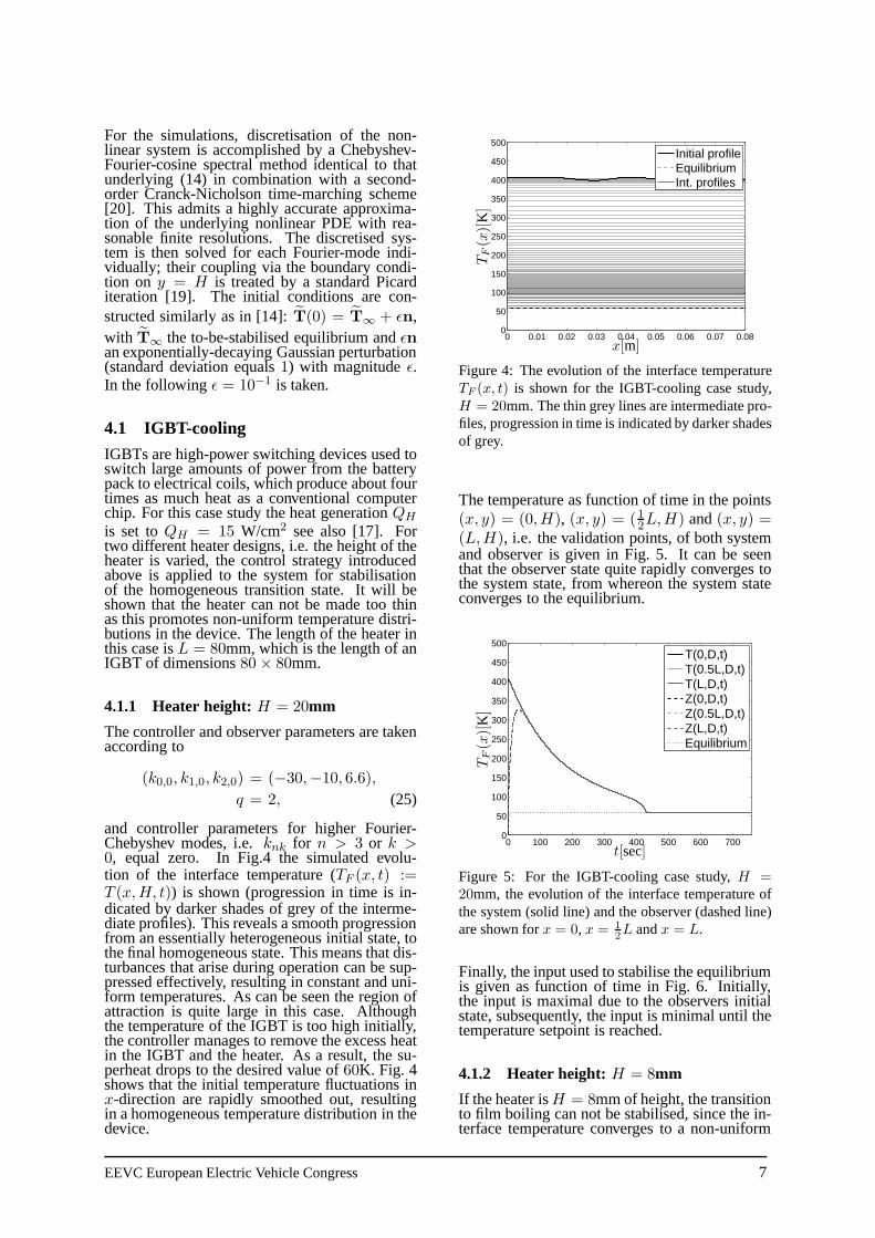
For the simulations, discretisation of the non-linear system is accomplished by a Chebyshev-Fourier-cosine spectral method identical to thatunderlying (14) in combination with a second-order Cranck-Nicholson time-marching scheme[20]. This admits a highly accurate approxima-tion of the underlying nonlinear PDE with rea-sonable finite resolutions. The discretised sys-tem is then solved for each Fourier-mode indi-vidually; their coupling via the boundary condi-tion on y = H is treated by a standard Picarditeration [19]. The initial conditions are con-structed similarly as in [14]:T(0) = T∞ + ǫn,with T∞ the to-be-stabilised equilibrium andǫnan exponentially-decaying Gaussian perturbation(standard deviation equals1) with magnitudeǫ.In the followingǫ = 10−1 is taken.
4.1 IGBT-cooling
IGBTs are high-power switching devices used toswitch large amounts of power from the batterypack to electrical coils, which produce about fourtimes as much heat as a conventional computerchip. For this case study the heat generationQH
is set toQH = 15 W/cm2 see also [17]. Fortwo different heater designs, i.e. the height of theheater is varied, the control strategy introducedabove is applied to the system for stabilisationof the homogeneous transition state. It will beshown that the heater can not be made too thinas this promotes non-uniform temperature distri-butions in the device. The length of the heater inthis case isL = 80mm, which is the length of anIGBT of dimensions80× 80mm.
4.1.1 Heater height: H = 20mm
The controller and observer parameters are takenaccording to
(k0,0, k1,0, k2,0) = (−30,−10, 6.6),
q = 2, (25)
and controller parameters for higher Fourier-Chebyshev modes, i.e.knk for n > 3 or k >0, equal zero. In Fig.4 the simulated evolu-tion of the interface temperature (TF (x, t) :=T (x,H, t)) is shown (progression in time is in-dicated by darker shades of grey of the interme-diate profiles). This reveals a smooth progressionfrom an essentially heterogeneous initial state, tothe final homogeneous state. This means that dis-turbances that arise during operation can be sup-pressed effectively, resulting in constant and uni-form temperatures. As can be seen the region ofattraction is quite large in this case. Althoughthe temperature of the IGBT is too high initially,the controller manages to remove the excess heatin the IGBT and the heater. As a result, the su-perheat drops to the desired value of60K. Fig. 4shows that the initial temperature fluctuations inx-direction are rapidly smoothed out, resultingin a homogeneous temperature distribution in thedevice.
0 0.01 0.02 0.03 0.04 0.05 0.06 0.07 0.080
50
100
150
200
250
300
350
400
450
500Initial profileEquilibriumInt. profiles
x[m]
TF(x)[
K]
Figure 4: The evolution of the interface temperatureTF (x, t) is shown for the IGBT-cooling case study,H = 20mm. The thin grey lines are intermediate pro-files, progression in time is indicated by darker shadesof grey.
The temperature as function of time in the points(x, y) = (0,H), (x, y) = (12L,H) and(x, y) =(L,H), i.e. the validation points, of both systemand observer is given in Fig. 5. It can be seenthat the observer state quite rapidly converges tothe system state, from whereon the system stateconverges to the equilibrium.
0 100 200 300 400 500 600 7000
50
100
150
200
250
300
350
400
450
500T(0,D,t)T(0.5L,D,t)T(L,D,t)Z(0,D,t)Z(0.5L,D,t)Z(L,D,t)Equilibrium
t[sec]
TF(x)[
K]
Figure 5: For the IGBT-cooling case study,H =20mm, the evolution of the interface temperature ofthe system (solid line) and the observer (dashed line)are shown forx = 0, x = 1
2L andx = L.
Finally, the input used to stabilise the equilibriumis given as function of time in Fig. 6. Initially,the input is maximal due to the observers initialstate, subsequently, the input is minimal until thetemperature setpoint is reached.
4.1.2 Heater height: H = 8mm
If the heater isH = 8mm of height, the transitionto film boiling can not be stabilised, since the in-terface temperature converges to a non-uniform
EEVC European Electric Vehicle Congress 7
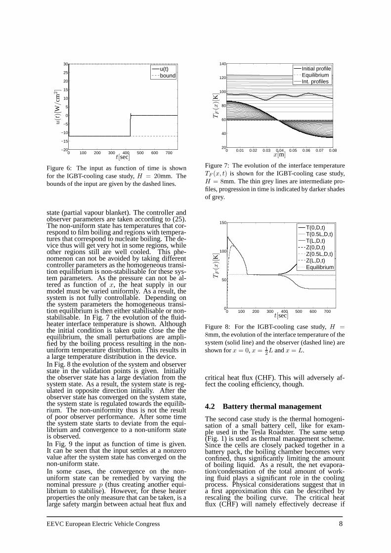
0 100 200 300 400 500 600 700−20
−15
−10
−5
0
5
10
15
20
25
30u(t)bound
t[sec]
u(t)[
W/cm
2]
Figure 6: The input as function of time is shownfor the IGBT-cooling case study,H = 20mm. Thebounds of the input are given by the dashed lines.
state (partial vapour blanket). The controller andobserver parameters are taken according to (25).The non-uniform state has temperatures that cor-respond to film boiling and regions with tempera-tures that correspond to nucleate boiling. The de-vice thus will get very hot in some regions, whileother regions still are well cooled. This phe-nomenon can not be avoided by taking differentcontroller parameters as the homogeneous transi-tion equilibrium is non-stabilisable for these sys-tem parameters. As the pressure can not be al-tered as function ofx, the heat supply in ourmodel must be varied uniformly. As a result, thesystem is not fully controllable. Depending onthe system parameters the homogeneous transi-tion equilibrium is then either stabilisable or non-stabilisable. In Fig. 7 the evolution of the fluid-heater interface temperature is shown. Althoughthe initial condition is taken quite close the theequilibrium, the small perturbations are ampli-fied by the boiling process resulting in the non-uniform temperature distribution. This results ina large temperature distribution in the device.In Fig. 8 the evolution of the system and observerstate in the validation points is given. Initiallythe observer state has a large deviation from thesystem state. As a result, the system state is reg-ulated in opposite direction initially. After theobserver state has converged on the system state,the system state is regulated towards the equilib-rium. The non-uniformity thus is not the resultof poor observer performance. After some timethe system state starts to deviate from the equi-librium and convergence to a non-uniform stateis observed.In Fig. 9 the input as function of time is given.It can be seen that the input settles at a nonzerovalue after the system state has converged on thenon-uniform state.In some cases, the convergence on the non-uniform state can be remedied by varying thenominal pressurep (thus creating another equi-librium to stabilise). However, for these heaterproperties the only measure that can be taken, is alarge safety margin between actual heat flux and
0 0.01 0.02 0.03 0.04 0.05 0.06 0.07 0.0820
40
60
80
100
120
140Initial profileEquilibriumInt. profiles
x[m]
TF(x)[
K]
Figure 7: The evolution of the interface temperatureTF (x, t) is shown for the IGBT-cooling case study,H = 8mm. The thin grey lines are intermediate pro-files, progression in time is indicated by darker shadesof grey.
0 100 200 300 400 500 600 7000
50
100
150T(0,D,t)T(0.5L,D,t)T(L,D,t)Z(0,D,t)Z(0.5L,D,t)Z(L,D,t)Equilibrium
t[sec]
TF(x)[
K]
Figure 8: For the IGBT-cooling case study,H =8mm, the evolution of the interface temperature of thesystem (solid line) and the observer (dashed line) areshown forx = 0, x = 1
2L andx = L.
critical heat flux (CHF). This will adversely af-fect the cooling efficiency, though.
4.2 Battery thermal management
The second case study is the thermal homogeni-sation of a small battery cell, like for exam-ple used in the Tesla Roadster. The same setup(Fig. 1) is used as thermal management scheme.Since the cells are closely packed together in abattery pack, the boiling chamber becomes veryconfined, thus significantly limiting the amountof boiling liquid. As a result, the net evapora-tion/condensation of the total amount of work-ing fluid plays a significant role in the coolingprocess. Physical considerations suggest that ina first approximation this can be described byrescaling the boiling curve. The critical heatflux (CHF) will namely effectively decrease if
EEVC European Electric Vehicle Congress 8

0 100 200 300 400 500 600 700−20
−15
−10
−5
0
5
10
15
20
25
30u(t)bound
t[sec]
u(t)[
W/cm
2]
Figure 9: The input as function of time is shown forthe IGBT-cooling case study,H = 8mm. The boundsof the input are given by the dashed lines.
the volume of the liquid phase of the boilingmedium drops below a certain minimum due tonet evaporation of the total amount of workingfluid. For this case study the boiling curve givenin Fig. 10 therefore is taken. The battery pack inthe Tesla Roadster can deliver up to 200 kW ofelectric power at 95% efficiency, see [18]. Thismeans the heat generation of an individual bat-tery cell can be as high as approximately0.33W/cm2. Hence, the heat generation is set toQH = 0.33W/cm2 for this case study.
0 2 4 6 8 10 12 14 16 180
0.1
0.2
0.3
0.4
0.5
0.6
0.7
Hea
t flu
x [W
/cm
2 ]
q
F(T
F)
QH
Figure 10: Nonlinear heat-flux functionqF (TF ) ac-cording to the boiling curve of aluminum vs. FC-72,see [9]. The dashed line represents the nominal heatsupplyQH .
4.2.1 Heater height: H = 3.5mm
Controller and observer parameters are again ac-cording to (25). In Fig.11 the simulated evolu-tion of the interface temperature (TF (x, t) :=T (x,H, t)) is shown (progression in time is againindicated by darker shades of grey of the interme-diate profiles). Similar as for the IGBT coolingexample an essentially heterogeneous initial stateis regulated to the final homogeneous state. Thismeans that disturbances that arise during oper-ation can be suppressed effectively, resulting inconstant and uniform temperatures in favour of a
uniform temperature distribution throughout thebattery pack. As can be seen, the region of attrac-tion is quite large in this case as well. The too lowinitial temperature is increased by the controllerby removing less heat from the battery. As a re-sult, the battery warms itself until it reaches thedesired temperature. The initial temperature fluc-tuations inx-direction are rapidly smoothed out,resulting in a homogeneous temperature distribu-tion in the cell. This means temperature fluctu-ations can be smoothed very effectively by thethermal management scheme.
0 0.01 0.02 0.03 0.04 0.05 0.062.5
3
3.5
4
4.5
5Initial profileEquilibriumInt. profiles
x[m]
TF(x)[
K]
Figure 11: The evolution of the interface temperatureTF (x, t) is shown for the battery-cooling case study,H = 3.5mm. The thin grey lines are intermediateprofiles, progression in time is indicated by darkershades of grey.
The temperature as function of time in the valida-tion points is given in Fig. 12. Again the observerstate quite rapidly converges to the system state.Due to the initial error, the system overshoots itsequilibrium value, however. After the observerstate has reached the equilibrium the system stateis regulated towards the equilibrium as well.
0 10 20 30 40 500
0.5
1
1.5
2
2.5
3
3.5
4
4.5
5T(0,D,t)T(0.5L,D,t)T(L,D,t)Z(0,D,t)Z(0.5L,D,t)Z(L,D,t)Equilibrium
t[sec]
TF(x)[
K]
Figure 12: For the battery-cooling case study,H =3.5mm, the evolution of the interface temperature ofthe system (solid line) and the observer (dashed line)are shown forx = 0, x = 1
2L andx = L.
EEVC European Electric Vehicle Congress 9
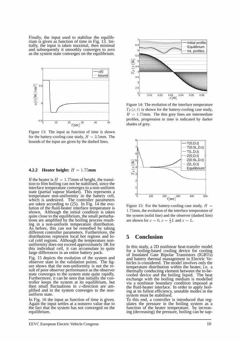
Finally, the input used to stabilise the equilib-rium is given as function of time in Fig. 13. Ini-tially, the input is taken maximal, then minimaland subsequently it smoothly converges to zeroas the system state converges on the equilibrium.
0 10 20 30 40 50−0.5
0
0.5
1u(t)bound
t[sec]
u(t)[
W/cm
2]
Figure 13: The input as function of time is shownfor the battery-cooling case study,H = 3.5mm. Thebounds of the input are given by the dashed lines.
4.2.2 Heater height: H = 1.75mm
If the heater isH = 1.75mm of height, the transi-tion to film boiling can not be stabilised, since theinterface temperature converges to a non-uniformstate (partial vapour blanket). This represents atemperature non-uniformity in the battery cell,which is undesired. The controller parametersare taken according to (25). In Fig. 14 the evo-lution of the fluid-heater interface temperature isshown. Although the initial condition is takenquite close to the equilibrium, the small perturba-tions are amplified by the boiling process result-ing in a non-uniform temperature distribution.As before, this can not be remedied by takingdifferent controller parameters. Furthermore, thedistributions represent local hot regions and lo-cal cold regions. Although the temperature non-uniformity does not exceed approximately3K forthis individual cell, it can accumulate to quitelarge differences in an entire battery pack.Fig. 15 depicts the evolution of the system andobserver state in the validation points. The fig-ure shows that the non-uniformity is not the re-sult of poor observer performance as the observerstate converges to the system state quite rapidly.Furthermore, it can be seen that initially the con-troller keeps the system at its equilibrium, butthen small fluctuations inx-direction are am-plified and in the system converges to the non-uniform state.In Fig. 16 the input as function of time is given.Again the input settles at a nonzero value due tothe fact that the system has not converged on theequilibrium.
0 0.01 0.02 0.03 0.04 0.05 0.062
2.5
3
3.5
4
4.5
5
5.5
6
6.5
7Initial profileEquilibriumInt. profiles
x[m]
TF(x)[
K]
Figure 14: The evolution of the interface temperatureTF (x, t) is shown for the battery-cooling case study,H = 1.75mm. The thin grey lines are intermediateprofiles, progression in time is indicated by darkershades of grey.
0 100 200 300 400 5000
1
2
3
4
5
6
7
8T(0,D,t)T(0.5L,D,t)T(L,D,t)Z(0,D,t)Z(0.5L,D,t)Z(L,D,t)Equilibrium
t[sec]
TF(x)[
K]
Figure 15: For the battery-cooling case study,H =1.75mm, the evolution of the interface temperature ofthe system (solid line) and the observer (dashed line)are shown forx = 0, x = 1
2L andx = L.
5 Conclusion
In this study, a 2D nonlinear heat-transfer modelfor a boiling-based cooling device for coolingof Insulated Gate Bipolar Transistors (IGBTs)and battery thermal management in Electric Ve-hicles is considered. The model involves only thetemperature distribution within the heater, i.e. athermally conducting element between the to-be-cooled device and the boiling liquid. The heatexchange with the boiling medium is modelledvia a nonlinear boundary condition imposed atthe fluid-heater interface. In order to apply boil-ing at its fullest efficiency, unstable modes in thesystem must be stabilised.To this end, a controller is introduced that reg-ulates the pressure in the boiling system as afunction of the heater temperature. by increas-ing (decreasing) the pressure, boiling can be sup-
EEVC European Electric Vehicle Congress 10
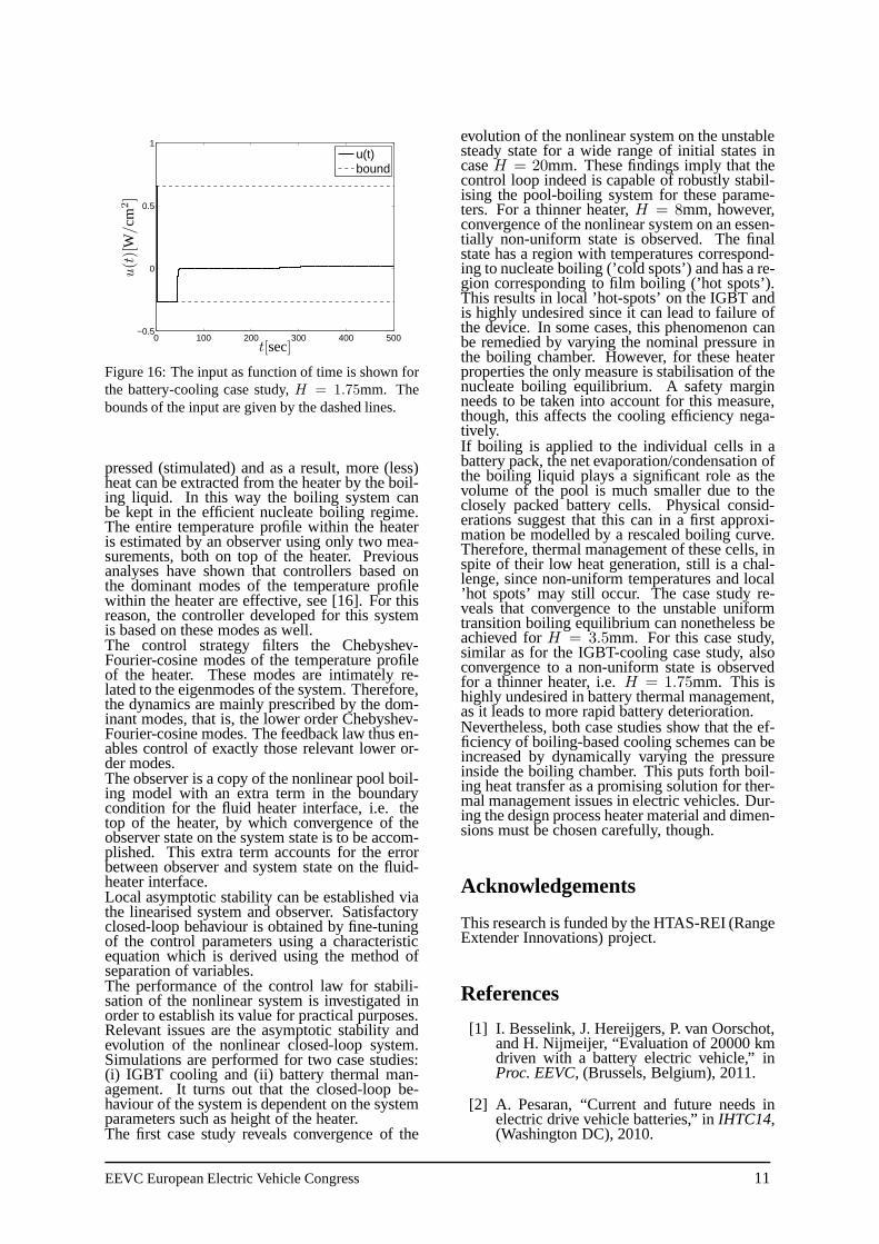
0 100 200 300 400 500−0.5
0
0.5
1u(t)bound
t[sec]
u(t)[
W/cm
2]
Figure 16: The input as function of time is shown forthe battery-cooling case study,H = 1.75mm. Thebounds of the input are given by the dashed lines.
pressed (stimulated) and as a result, more (less)heat can be extracted from the heater by the boil-ing liquid. In this way the boiling system canbe kept in the efficient nucleate boiling regime.The entire temperature profile within the heateris estimated by an observer using only two mea-surements, both on top of the heater. Previousanalyses have shown that controllers based onthe dominant modes of the temperature profilewithin the heater are effective, see [16]. For thisreason, the controller developed for this systemis based on these modes as well.The control strategy filters the Chebyshev-Fourier-cosine modes of the temperature profileof the heater. These modes are intimately re-lated to the eigenmodes of the system. Therefore,the dynamics are mainly prescribed by the dom-inant modes, that is, the lower order Chebyshev-Fourier-cosine modes. The feedback law thus en-ables control of exactly those relevant lower or-der modes.The observer is a copy of the nonlinear pool boil-ing model with an extra term in the boundarycondition for the fluid heater interface, i.e. thetop of the heater, by which convergence of theobserver state on the system state is to be accom-plished. This extra term accounts for the errorbetween observer and system state on the fluid-heater interface.Local asymptotic stability can be established viathe linearised system and observer. Satisfactoryclosed-loop behaviour is obtained by fine-tuningof the control parameters using a characteristicequation which is derived using the method ofseparation of variables.The performance of the control law for stabili-sation of the nonlinear system is investigated inorder to establish its value for practical purposes.Relevant issues are the asymptotic stability andevolution of the nonlinear closed-loop system.Simulations are performed for two case studies:(i) IGBT cooling and (ii) battery thermal man-agement. It turns out that the closed-loop be-haviour of the system is dependent on the systemparameters such as height of the heater.The first case study reveals convergence of the
evolution of the nonlinear system on the unstablesteady state for a wide range of initial states incaseH = 20mm. These findings imply that thecontrol loop indeed is capable of robustly stabil-ising the pool-boiling system for these parame-ters. For a thinner heater,H = 8mm, however,convergence of the nonlinear system on an essen-tially non-uniform state is observed. The finalstate has a region with temperatures correspond-ing to nucleate boiling (’cold spots’) and has a re-gion corresponding to film boiling (’hot spots’).This results in local ’hot-spots’ on the IGBT andis highly undesired since it can lead to failure ofthe device. In some cases, this phenomenon canbe remedied by varying the nominal pressure inthe boiling chamber. However, for these heaterproperties the only measure is stabilisation of thenucleate boiling equilibrium. A safety marginneeds to be taken into account for this measure,though, this affects the cooling efficiency nega-tively.If boiling is applied to the individual cells in abattery pack, the net evaporation/condensation ofthe boiling liquid plays a significant role as thevolume of the pool is much smaller due to theclosely packed battery cells. Physical consid-erations suggest that this can in a first approxi-mation be modelled by a rescaled boiling curve.Therefore, thermal management of these cells, inspite of their low heat generation, still is a chal-lenge, since non-uniform temperatures and local’hot spots’ may still occur. The case study re-veals that convergence to the unstable uniformtransition boiling equilibrium can nonetheless beachieved forH = 3.5mm. For this case study,similar as for the IGBT-cooling case study, alsoconvergence to a non-uniform state is observedfor a thinner heater, i.e.H = 1.75mm. This ishighly undesired in battery thermal management,as it leads to more rapid battery deterioration.Nevertheless, both case studies show that the ef-ficiency of boiling-based cooling schemes can beincreased by dynamically varying the pressureinside the boiling chamber. This puts forth boil-ing heat transfer as a promising solution for ther-mal management issues in electric vehicles. Dur-ing the design process heater material and dimen-sions must be chosen carefully, though.
Acknowledgements
This research is funded by the HTAS-REI (RangeExtender Innovations) project.
References
[1] I. Besselink, J. Hereijgers, P. van Oorschot,and H. Nijmeijer, “Evaluation of 20000 kmdriven with a battery electric vehicle,” inProc. EEVC, (Brussels, Belgium), 2011.
[2] A. Pesaran, “Current and future needs inelectric drive vehicle batteries,” inIHTC14,(Washington DC), 2010.
EEVC European Electric Vehicle Congress 11

[3] P. Ramadasset al., “Capacity fade of sony18650 cells cycled at elevated tempera-tures: Capacity fade analysis,”J. PowerSources, vol. 112, pp. 614–620, 2002.
[4] A. Pesaran, A. Vlahinos, and S. Burch,“Thermal performance of EV and HEV bat-tery modules and packs,” inProc. 14th Int.EV Symp., Orlando, 1997.
[5] R. van Gils, M. Speetjens, and H. Nijmeijer,“Boiling heat transfer in electric vehicles,”Tech. Rep. DC 2011.52, Eindhoven U. ofTech., Dept. of Mech. Eng., 2011.
[6] H. van Ouwerkerk, “Burnout in pool boil-ing the stability of boiling mechanisms,”Int. J. Heat Mass Transfer, vol. 15, no. 1,pp. 25–34, 1972.
[7] V. Dhir, “Boiling heat transfer,”Annu. Rev.Fluid Mech., vol. 30, pp. 365–401, 1998.
[8] I. Mudawar, “Assessment of high-heat-flux thermal management schemes,”IEEETrans. Comp. Packaging Technol., vol. 24,no. 2, pp. 122–141, 2001.
[9] H. Auracher and W. Marquardt, “Heattransfer characteristics and mechanismsalong entire boiling curves under steady-state and transient conditions,”Int. J. HeatFluid Flow, vol. 25, pp. 223–242, 2004.
[10] J. Blum, W. Marquardt, and H. Auracher,“Stability of boiling systems,”Int. J. HeatMass Transfer, vol. 39, no. 14, pp. 3021–3033, 1996.
[11] J. Blumet al., “Temperature wave propaga-tion as a route from nucleate to film boil-ing?,” in Proc. 2nd int. symp. two-ph. flowmod. and exp., (Rome, Italy), 1999.
[12] M. Speetjens, A. Reusken, and W. Mar-quardt, “Steady-state solutions in a nonlin-ear pool boiling model,”Com. Nonl. Sci.Num. Sim., vol. 13, pp. 1475–1494, 2008.
[13] M. Speetjenset al., “Stability analysisof two-dimensional pool-boiling systems,”SIAM J. Applied Dyn. Sys., vol. 7, pp. 933–961, 2008.
[14] R. van Gils, M. Speetjens, and H. Nij-meijer, “Feedback stabilisation of a one-dimensional nonlinear pool-boiling sys-tem,” Int. J. Heat Mass Transfer, vol. 53,pp. 2393–2403, May 2010.
[15] R. van Gils, M. Speetjens, and H. Nij-meijer, “Feedback stabilisation of a two-dimensional pool-boiling system by modalcontrol,” 2011. submitted for publication.
[16] R. van Gils, M. Speetjens, and H. Nijmeijer,“Feedback stabilisation of two-dimensionalnon-uniform pool-boiling states,” inHeatTransfer XI, (Tallin, Estonia), pp. 215 –226, WIT Press, 2010.
[17] R. Chu et al., “Review of cooling tech-nologies for computer products,”IEEETrans. Device Materials Reliability, vol. 4,pp. 568–585, 2004.
[18] G. Berdichevsky, K. Kelty, J. Straubel, andE. Toomre, “The tesla roadster battery sys-tem.” Tesla Motors, August 16, 2006.
[19] E. Kreyszig,Advanced Engineering Math-ematics. Wiley, New York, 1999.
[20] C. Canutoet al., Spectral Methods in FluidDynamics. Springer, New York, 1987.
AuthorsRob van Gils received the M.Sc.degree (with great distinction)in Mechanical Engineering fromEindhoven University of Technol-ogy, in 2008. Since September2008, he is a Ph.D. candidate withthe Dynamics and Control groupat the Mechanical Engineering De-partment of Eindhoven Universityof Technology.
Michel Speetjens received his PhDdegree (with honours) in AppliedPhysics from Eindhoven Univer-sity of Technology in 2001. Dur-ing 2002-2005 he was postdoctoralresearcher at CSIRO, Australia andRWTH-Aachen, Germany. Since2006 he holds a position as as-sistant professor in thermal trans-port phenomena at Mechanical En-gineering, Eindhoven University ofTechnology.
Henk Nijmeijer (1955) obtainedhis MSc-degree and PhD-degreein Mathematics from the Univer-sity of Groningen, Groningen, theNetherlands, in 1979 and 1983,respectively. From 1983 untill2000 he was affiliated with the De-partment of Applied Mathematicsof the University of Twente, En-schede, the Netherlands. Since,1997 he was also part-time affili-ated with the Department of Me-chanical Engineering of the Eind-hoven University of Technology,Eindhoven, the Netherlands. Since2000, he is a full professor at Eind-hoven, and chairs the Dynamicsand Control group.
EEVC European Electric Vehicle Congress 12


![Flow boiling heat transfer of HFO1234yf and HFC32 ... boiling heat transfer of... · boiling heat transfer coefficient is calculated from the pool boiling correlation of Cooper [7].](https://static.fdocuments.net/doc/165x107/6060f16e796df51c036c4972/flow-boiling-heat-transfer-of-hfo1234yf-and-hfc32-boiling-heat-transfer-of.jpg)