Boiler efficiency measurement · In all of the cases this is the largest loss, which determines...
46
Boiler efficiency measurement Department of Energy Engineering
Transcript of Boiler efficiency measurement · In all of the cases this is the largest loss, which determines...

Boiler efficiency measurement
Department of Energy Engineering

Contents• Heat balance on boilers• Efficiency determination• Loss categories• Fluegas condensation principals• Seasonal efficiency• Emission evaluation

StoichiometryCombustion is an oxidation process,
which is an exotherm chemical reaction:• Exotherm - heat is produced by reaction• Endotherm - heat is needed for keeping up reaction• Authoterm - neutral from heat viewpoint,
(reaction do not need or produce any heat)
Base equations of combustion: C + O2 = CO2 + heat2H2 + O2 = 2H2O + heatS + O2 = SO2 + heat

Air as Oxygen source for combustionFor combustion two component is needed:• Combustible element or material• OxygenBut for feeding oxygen generally ambient air is usedexcept for some missile, military and welding techniquesComposition of air: Oxygen O2 21% [V/V, mol/mol]
Nitrogen N2 78% [V/V, mol/mol]Others (CO2, rare gas, etc.)1% [V/V, mol/mol]
Simplification for combustion calculations:Composition of air: Oxygen O2 21% [V/V, mol/mol]
Nitrogen N2 79% [V/V, mol/mol]By mass: Oxygen O2 23.3% [m/m]
Nitrogen N2 76.7% [m/m]

Excess air factor λλλλ• A stoichiometric mixture of air and fuel is one that contains just
sufficient oxygen for the complete combustion of the fuel - a mixture which has an excess of air is termed a weak mixture, - and one which has a deficiency of air is termed a rich mixture.
• Normally it is going to be burnt fuel totally in order to utilize all the possibility for energy generation, which needs at least theoretical air quantity or generally a bit more.
• The excess air factor:
[-]λ =
Air actually useAir stoichiometrically necessary
AA=
0

Determination of optimal excess air factor

Excess air calculation from measured data
From equations: V‘d = Vo‘d + (λ-1) Lo' , and
0.21 . (λ-1) Lo' = O2fluegas . (Vo‘d + (λ-1) . Lo' )
taking into account that Vo‘d y Lo' can get:
fluegasO22121
−=λ

Excess air factor variation

Determination of optimal excess air factorDepends on several conditions:• Fuel type, combustion system, burner construction,
pollutant emission limits, etc.• Some usual values of the excess air factor :
1.2 – 1.5pulverized solid fuel1.4 - 2.0coarse solid fuel1.1 - 1.4oil1.03 - 1.3gas
λfuel

Heat balance on boilers
Input power sum is equal with output power sum: ΣQin = ΣQout Input heat components: • Input heat in chemical bound of fuel. Qfuel = Σ B ⋅ Hi • Input physical heat of fuel: Qfuelphysical = Σ B ⋅ cpfuel ⋅ (tin - tamb ) • Input heat of hot air: Qair = Σ B ⋅ λ ⋅ µLo’ ⋅ cpair ⋅ (tin – tamb ) • Other
Input heat: Qin = Qfuel + Qfuelphysical + Qin + Qother
otherambfuelfuelambairpair'LoiinQ))tt(c)tt(cH(BQ && +−⋅+−⋅⋅⋅+⋅= µλ

Definition of boiler efficiency
Output power can be divided into two categories: Qin = Quseful + Qloss
Quseful = Qin – Qloss , Two forms of boiler efficiency determination can be gained.
in
loss
in
usefulboiler
1 &&
&&
−==η
direct indirect

Direct efficiency
• Useful heat power can be determined from mass flow rate of heat transfer medium and from inlet and outlet enthalpy:
• Quseful = m ⋅ (hout – hin ) • For determination of direct boiler efficiency fuel and heat
transfer medium flow rate needs to be measured in addition to inlet and outlet medium pressure measurement.
• Direct efficiency does not give information about reasons of boiler efficiency variation.
• It does not give any idea how to reduce loss and increase efficiency

Indirect efficiency
Different types of loss can be separated into two groups:• Firing type losses
are originated from not total or not complete combustion of the fuel, which means that unburntcombustible parts remaining after combustion end
• Heat exchanger type lossesmeans that some part of generated heat by combustion goes to waste, not to useful purpose, not to heat transfer medium

Firing type losses
Different forms of firing losses: ξgas - unburnt gas (CO,CxHy) ξsoot - soot ξcoke - coke ξflyash – combustible part of flying ash ξash - combustible part of bottom ash Considering above mentioned losses can be calculated the firing efficiency: ηF = 1 - ( ξgas+ ξsoot+ ξcoke+ ξflyash+ ξash)

Loss calculation• In case of oil and gas firing, when it fulfils environmental
protection requirements, firing loss is neglectable. In case of solid fuel firing generally it is worth to take into account. In this case it is necessary to distinguish inlet fuel flow fromactually burning, fluegas-developing fuel flow.
Bfg = ηηηηF ⋅⋅⋅⋅ B
• Loss quantity can be determined from operational measurement results.
Qloss = massflow ⋅ burnable content ⋅ heating value of burnable part
• Loss factor is given by the ratio of loss heat power and input power.
ξξξξ = Qloss / Qin

Heat exchanger type losses
• Heat exchanger type loss is the common name of heat produced by combustion, but going another direction than heat transfer medium, which is actually loss.
• Different forms of heat exchanger type losses: • ξfg – fluegas heat loss
ξrad – radiation heat lossξashheat – ash physical heat loss

Fluegas heat loss• Heat delivered to the ambient air because flue gas has higher
temperature than initial or ambient one. • In all of the cases this is the largest loss, which determines
mainly the boiler efficiency.• At an up to date boiler it is generally in between ξfg = 5 - 10 % • At earlier constructions it is in between ξfg = 10 - 15 % • When fluegas is cooled below water vapor dew-point
temperature (which is generally in between 40-60°C) extra heat can be gained. It can cause that overall boiler efficiency can be above 100 % in case when input heat is calculated from LHV.

Calculation of flue gas loss factor ξfg = Qfg / Qin Qfg = mfg ⋅ (hfgout - hfgamb) = B ⋅ (µVo’+(λ-1) ⋅ µLo’) ⋅ cpfg ⋅ (tfgout – tamb)
−⋅⋅⋅−+⋅ µλµ[ ]
i
ambairLfgoutfgLfgfg H
tcrKtcK ⋅⋅⋅−−⋅⋅−⋅−+= 000 *)1( µλµλµξ

Fluegas heat loss variation in case of
fuel oil S firing

Utilization of condensation heat

Condensation of fluegas water content• Fluegas can be considered as ideal mixture of different
gas components• Accoding to Dalton’s law he pressure of a mixture of
gases can be defined as the summation of partial pressure of each components:
• When fluegas temperature drop down below saturation temperature belonging to partial pressure of water in the fluegas
• Partial pressure of water in the fluegas:
'L)1('VwaterH12.11p'V
Vpp00
absO2H
absO2H ⋅−++⋅== λ

Saturation temperature and pressure values
0 bar0 °C0.012 bar10 °C0.023 bar20 °C0.042 bar30 °C0.074 bar40 °C0.094 bar45 °C0.12 bar50 °C0.157 bar55 °C0.2 bar60 °C1 bar100 °C
Saturation pressure Saturation temperature

Variation of flue gas dew point with excess air factor
1 1.1 1.2 1.3 1.450
55
60
th λh( )
λh
.
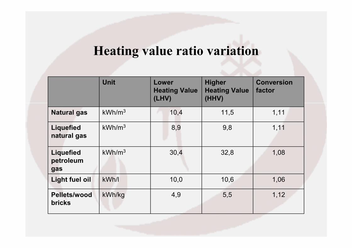
Heating value ratio variation
1,125,54,9kWh/kgPellets/wood bricks
1,0610,610,0kWh/lLight fuel oil
1,0832,830,4kWh/m3Liquefied petroleum gas
1,119,88,9kWh/m3Liquefied natural gas
1,1111,510,4kWh/m3Natural gas
Conversion factor
Higher Heating Value(HHV)
Lower Heating Value(LHV)
Unit

Radiation type loss
• Radiation type loss is called the heat transferred to the ambient air by outer surface of the boiler.
• The name originates from ancient boiler construction, where brick works actually radiated heat to the ambient. Nowadays thisheat is transferred mainly by convection, but the name remains the same.
• Actual value can be calculated according to heat transfer rules considering actual insulation solution.
• This loss factor varies in between ξrad = 0.5 - 1.0 % referring to maximal load. But the heat loss power is independent from load level, it is constant. (Qrad = const.).
• This cause that loss factor is in inverse proportionality with load.( 1% loss at nominal load increases up to 5% at 20% part load)

Comparison of direct and indirect boiler efficiency
• Both methods shall give the same value. But in real some difference can be experienced because of measurement inaccuracies.
• Generally determination by indirect method is simpler, because fuel and heat transfer medium measurement is not needed.
• Furthermore indirect method gives information on waste heat distribution and can be information base of efficiency increment.
• Direct method cannot be used for this purpose, but it can be good control of indirect method.

Boiler efficiency variation at part load

Efficiency variationand assessment of seasonal efficiency
Load independent losses
Load dependent losses
Effective energy 1/ K
0 1 Workload
qB/ K
Stan
dard
ized f
uel in
put q
F
qF = Q´F/(Q`K*tB)
β = Q´H/(Q`K*tB) with QK: Nominal boiler capacit tB: Running time of the boiler QF: Firing power QH: Useful power From these values the average efficiency ηa(β) can be calculated
ηa(β) = β*ηK/(β-β*qB + qB)

Atmospheric premix type burner

Atmospheric premix type burnerwith open combustion system – wall hung boiler

Atmospheric premix type burnerwith open combustion system – floor standing boiler

Atmospheric premix type burnerwith open combustion system – floor standing boiler

Examples for different combustion air supply
Open Closed Condensing type Combustion system

Combustion system of condensation type boilers

Condensation type wall-hung boiler

Measurement arrangement

Direct efficiency calculation
ηDQusefulQfiring
Direct efficiency of the boiler:
lower heating valuekJm3
Hi 34000:=
Volume flow of natural gas;Vgaswhere Qfiring Vgas Hi⋅
in- and outlet temperature of cooling water tcwouttcwin
tcwin tcwout+
2temperature specific heat of water at cw
temperature tcwindensity of water atρw
useful power;Qusefulwhere:
Quseful Vcw ρ cw⋅ cw⋅ tcwout tcwin−( )⋅

Parameter dependence on temperature• Density of waterρw(20ºC) = 998.5 kg/m3
• Specific heat variation of water:
15 25 35 45 55 65 75 854.18
4.185
4.19
4.195
4.2
cvm t( )
t .

Flue gas heat loss calculation
where µair = 14.981 [kg/kg]µfg0= 15.981 [kg/kg]cfg = 1.107 [kJ/kg]cair = 1.04 [kJ/kg]K: specific quantity of condensate water for 1 m3 or 1 kg natural gas
(from measured data)r = 2510 kJ/kg evaporization heat of waterHi – Lower Heating Value by mass [kJ/kg]
[ ]i
ambairLfgoutfgLfgfg H
tcrKtcK ⋅⋅⋅−−⋅⋅−⋅−+= 000 *)1( µλµλµξ

Density variation of natural gas
ρg0 0.72 kgm3⋅:= ρg t pg,( ) ρg0
273t 273+⋅
pg 101325+
101325⋅:=
10 15 20 25 300.66
0.68
0.7
0.72
ρg t 2000,( )
ρg t 2500,( )
ρg t 3000,( )
t .

Indirect efficiency calculation• ηηηηind = 100%-ξξξξfg-ξξξξrad
• ξξξξrad = αααα.Aouter.(twall-tamb)/Qfiring [-]• Where: α = 20 W/m2K - heat transfer coefficientAouter – outer surface of the boiler [m2]twall – outer surface temperature [ºC]tamb – ambient temperature [ºC]

Evaluation of emission measurement
ppm CxHy 18:=Unburnt hydrocarbons:ppmCO 70:=Carbon monoxyde: ppmNOx 150:=Nitrogen oxydes:
Measured emission values of combustion process dependent pollutants:
% O2r 3:=Refeence oxygen content of flue gas for evaluation of emission limits:
λ 1.235=λ 2121 O2−:=Operational excess air factor:
%O2 4:=Measured oxygen content in fluegas:

Evaluation of emission measurement
mg/m3 CxHyrm 49.327=CxHyrm21 O2r−21 O2− CxHym⋅:=Reference value:
mg/m3 CxHym 46.586=CxHym CxHyMC4H1022.41⋅:=kg/kmolMC4H10 58:=
mg/m3 COrm 92.606=COrm21 O2r−21 O2− COm⋅:=Reference value:
mg/m3 COm 87.461=COm COMCO22.41⋅:=kg/kmolMCO 28:=
mg/m3 NOxrm 326.01=NOxrm21 O2r−21 O2− NOxm⋅:=
Reference value:
mg/m3 NOxm 307.898=NOxm NOxMNO222.41⋅:=kg/kmolMNO2 46:=

Summary and comparison of emission values
Emission values are refernced to dry (water free) fluegas at 273K, 101,3 kPa, 3% oxygen content.
NOxrm 326.01= mg/m3 < 350 mg/m3
COrm 92.606= mg/m3 < 100 mg/m3
CxHyrm 49.327= mg/m3 < 50 mg/m3

SummaryYou are already familiar with• Heat balance on boilers• Efficiency determination• Loss categories• Fluegas condensation principals• Seasonal efficiency• Emission evaluation

Thank You for Your Attention !