BOE CADD STANDARDS - Los Angeles · currently uses Autodesk AutoCAD® for Traditional design...
129
BOE CADD STANDARDS
Transcript of BOE CADD STANDARDS - Los Angeles · currently uses Autodesk AutoCAD® for Traditional design...
BOE CADD
STANDARDS

Department of Public Works
1149 S Broadway, Los Angeles, CA 90015 October 18, 2018 Page | 2
Bureau of Engineering
CADD Standards
Preface The Bureau of Engineering is committed to improving the quality of project delivery offered to all our Clients. By producing electronic design data consistently, communication among designer, owner and contractor can be streamlined resulting in cost savings and greater project efficiency. In an organization as large and diverse as the Bureau of Engineering, developing, maintaining and
implementing new CAD standards can be a daunting task however, the alternative of poor consistency,
unpredictability and inaccuracy of contract drawings can result in significant capital cost. Any attempt at
the task of standardization unquestionably results in not meeting the needs of all users in all cases. To
minimize the transition challenges, this manual was developed through a consensus of a variety of Bureau
CADD users, Engineers and Architects and in close compliance with the National CAD Standard. Tools &
Resources were also developed and are available on the Bureau’s website.
The goal of this document is to enhance the standardization of BOE drawings and digital files while reaffirming compliance with the latest National CAD Standard published by the National Institute of Building Sciences. This Standard will serve as a foundation for information sharing and enhancing coordination between the designer, engineer, contractor and owner. It will also be used as a basis for future development of BIM workflows and 3D Modeling standards for the Bureau of Engineering. In this document the acronym CADD will be used repeatedly. CADD is defined as Computer Aided Drafting
& Design. The Bureau has recognized that the evolving nature of computer design technology is obscuring
the divide between Drafting, Design and Engineering Analysis. Modern CADD tools do far more than
drafting; now requiring Engineers, Architects and Owners to become competent users. At the same time
however, the standardization of plan production remains of top importance to be successful in
implementing advance uses of modern technology.
The CADD Standards Committee is committed to the continued improvement and enhancing the usability
of this standard. To be successful, we are reliant upon the cooperation and participation of all Bureau
professionals. To the extent possible, we request that you structure your projects and data in accordance
with this Standard, augmenting it only in those cases where your project cannot be sufficiently classified,
organized or represented according to it. Compliance will ensure your project data can be freely exchanged
with other Bureau divisions and adopters of this Standard.
Version updates: To denote changes from version to version, a delta (Δ) will be placed where material has
been deleted and red text where material has been added or revised.

Department of Public Works
1149 S Broadway, Los Angeles, CA 90015
October 18, 2018 Page | 3
Bureau of Engineering
CADD Standards
Contents
1.0 Project Folder Structure ............................................................................................................................ 7
1.1 File Naming Conventions ................................................................................................................ 10
1.1.1 Project File Types ................................................................................................................ 11
1.1.2 Project File Naming ............................................................................................................ 13
1.2 Library Files ..................................................................................................................................... 15
1.2.1 Library File Types ................................................................................................................ 15
1.2.2 Library File Naming ............................................................................................................. 15
1.3 Sheet Naming Overview .................................................................................................................. 16
1.3.1 Sheet Naming ..................................................................................................................... 16
2.0 Sheet Organization .................................................................................................................................... 20
2.1 Sheet Size ........................................................................................................................................ 20
2.2 Sheet Layout.................................................................................................................................... 20
2.2.1 Drawing Area ...................................................................................................................... 21
2.2.2 Title Block Area ................................................................................................................... 23
2.2.3 Production Data Area ......................................................................................................... 23
2.2.4 Note Area ........................................................................................................................... 24
2.2.5 Cover Sheet ........................................................................................................................ 25
2.3 Supplemental Sheets ...................................................................................................................... 26
3.0 Drawing Conventions ................................................................................................................................ 27
3.1 Drawing Standards .......................................................................................................................... 27
3.1.1 Drawing Orientation & North Arrow .................................................................................. 27
3.1.2 Grid System ........................................................................................................................ 31
3.1.3 Coordinate Systems ............................................................................................................ 32
3.1.4 Drafting Precision ............................................................................................................... 33
3.1.5 Scales & Units ..................................................................................................................... 34
3.1.6 Lines .................................................................................................................................... 36
3.1.7 Linetypes ............................................................................................................................ 38

Department of Public Works
1149 S Broadway, Los Angeles, CA 90015
October 18, 2018 Page | 4
Bureau of Engineering
CADD Standards
3.1.8 Dimensions ......................................................................................................................... 46
3.1.9 Notations ............................................................................................................................ 51
3.1.10 Cross References .............................................................................................................. 55
3.1.11 Symbols ............................................................................................................................ 56
3.2 Sheet Types ..................................................................................................................................... 59
3.2.0 Sheet Type 0 – General ...................................................................................................... 59
3.2.1 Sheet Type 1 - Plans ........................................................................................................... 60
3.2.2 Sheet Type 2 - Elevations ................................................................................................... 74
3.2.3 Sheet Type 3 - Sections ...................................................................................................... 76
3.2.4 Sheet Type 4 - Large-Scale Views ....................................................................................... 78
3.2.5 Sheet Type 5 - Details ......................................................................................................... 79
3.2.6 Sheet Type 6 - Schedules and Diagrams ............................................................................. 81
3.2.7 Sheet Types 7- Isometrics ................................................................................................... 82
3.2.8 Sheet Type 8 - 3D Representations .................................................................................... 83
3.3 Mock-up Drawing Set ...................................................................................................................... 86
3.3.1 Mock-Up Set Procedures .................................................................................................... 86
3.3.2 Mock-Up Worksheet .......................................................................................................... 88
4.0 Symbols ..................................................................................................................................................... 90
4.1 Symbols Scale .................................................................................................................................. 90
4.2 Symbols Classification ..................................................................................................................... 90
4.2.1 Identity (ID) ......................................................................................................................... 90
4.2.2 Line (LINE) ........................................................................................................................... 90
4.2.3 Material (MATL) ................................................................................................................. 90
4.2.4 Object (OBJ) ........................................................................................................................ 91
4.2.5 Reference (REF) .................................................................................................................. 91
4.2.6 Text (TEXT) .......................................................................................................................... 91
4.3 Symbols Organization ..................................................................................................................... 92
5.0 Notations ................................................................................................................................................... 93
5.1 General Notes / Notice to Contractor ............................................................................................. 93
Department of Public Works
1149 S Broadway, Los Angeles, CA 90015
October 18, 2018 Page | 5
Bureau of Engineering
CADD Standards
5.2 General Discipline Notes ................................................................................................................. 96
5.3 General Sheet Notes ....................................................................................................................... 96
5.4 Sheet Keynotes................................................................................................................................ 98
5.5 Note Hierarchy ................................................................................................................................ 99
6.0 Schedules ................................................................................................................................................ 102
6.1 Schedule Format ........................................................................................................................... 102
6.1.1 Heading............................................................................................................................. 104
6.1.2 Subheading ....................................................................................................................... 104
6.1.3 Mark Column .................................................................................................................... 104
6.1.4 Item Description Column .................................................................................................. 104
6.1.5 Item Data Column ............................................................................................................ 104
6.1.6 Notes Column ................................................................................................................... 104
6.2 Building a Schedule ....................................................................................................................... 105
6.2.1 Simple vs. Expanded Schedules ........................................................................................ 105
6.2.2 Column Identifiers ............................................................................................................ 106
7.0 Terms & Abbreviations ........................................................................................................................... 109
7.1 Terms............................................................................................................................................. 109
7.2 Abbreviations ................................................................................................................................ 109
8.0 Layer Naming Convention ....................................................................................................................... 110
8.1 Layer Properties ............................................................................................................................ 110
8.1.2 Layer Name Format .......................................................................................................... 111
8.1.3 Discipline Designator, LEVEL 1.......................................................................................... 112
8.1.4 Major Group ..................................................................................................................... 113
8.1.5 Minor Group ..................................................................................................................... 113
8.1.6 Status (phase) ................................................................................................................... 114
8.2 Drawing View Layer List ................................................................................................................ 115
8.2.1 Drawing View Field Codes ................................................................................................ 115
8.2.2 Drawing View Layer Names .............................................................................................. 115
8.3 Annotation Layer List .................................................................................................................... 116

Department of Public Works
1149 S Broadway, Los Angeles, CA 90015
October 18, 2018 Page | 6
Bureau of Engineering
CADD Standards
8.3.1 Annotation Layer Names .................................................................................................. 116
8.4 Layer Colors ................................................................................................................................... 117
8.5 Creating a New Layer .................................................................................................................... 118
8.5.1 Adding New Layers to the Template ................................................................................ 118
9.0 Codes ....................................................................................................................................................... 119
9.1 Identification of Regulatory Information ...................................................................................... 120
9.2 The Plan Review Process ............................................................................................................... 120
9.2.1 Plan Review and Inspections ............................................................................................ 122
9.3 Overview of Regulatory Information ............................................................................................ 123
9.3.1 State/Local Codes and Amendments ............................................................................... 124
9.3.2 Federal Regulations .......................................................................................................... 124
9.3.3 Zoning Ordinances and Zoning Codes .............................................................................. 126
9.4 The Design Process........................................................................................................................ 127
10.0 Plotting Guidelines ................................................................................................................................ 128
10.1 Plot Styles: ................................................................................................................................... 128
11.0 References ............................................................................................................................................ 129

Department of Public Works
1149 S Broadway, Los Angeles, CA 90015
October 18, 2018 Page | 7
Bureau of Engineering
CADD Standards
1.0 Project Folder Structure
Organizing project files effectively and consistently is critical to the success of design, plan production and
data reuse potential among Divisions, City Agencies, Design Consultants and Contractors. Without adequate
project controls, the ability to manage the quantity, storage directory and content of files significantly
reduces. The computer operating systems folder or directory tools are relied upon for effective project data
management.
Typically, several projects at different stages are stored on a server at any given time. PC operating systems
software will not allow two identical file names to exist in the same folder in the system. Therefore, several
separate folders are required to store similar data types for different projects.
Quite commonly, many Divisions within the Bureau of Engineering (BOE) store CAD and associated reference
files in a separate directory (and some Divisions a different server) than other project data. This provides
more flexibility and control of these critical project files as well as minimizes the potential for inadvertent
corruption of data by an inexperienced user. See Figure 1.0-1.
Figure 1.0-1 Project Folder
Most BOE and City projects are linked to a project work order for expense tracking and other metrics,
additionally, most BOE projects are assigned a Capital Improvement Project (CIP) number containing less
characters than a Work Order. Logically, these two assigned values are used as the primary identifiers for a
project folder. See Figure 1.0-2 for typical project path and folder name structure.
Figure 1.0-2 Typical Project Path and Folder

Department of Public Works
1149 S Broadway, Los Angeles, CA 90015
October 18, 2018 Page | 8
Bureau of Engineering
CADD Standards
Note: When more than one Work Order is associated with a project, a primary Work Order shall be
designated and subsequently displayed first on all project documents.
The National CAD Standard recommends 8 characters for a project folder name. For convenience, however,
some BOE Divisions add the CIP number as a suffix since most projects are identified by CIP number in
conversation. Using a work order is required while using the CIP number is optional. Once the decision has
made whether to include the CIP number or not, all project folders shall be name accordingly and
consistently across the entire Division.
The next level of subfolders called “phase folders” should consist of names identifying the progression of the
project according to BOE’s five established project phases (Pre-Design, Design, Bid & Award, Construction
and Post Construction). Archive files are created as the project progresses from phase to phase. Although
archive data is desired and valuable, to minimize duplicate file creation and data storage requirements,
several phases of data are contained in the Design phase folder. See Figure 1.0-3. It is acceptable to separate
the Pre-Design and Bid & Award phases of the project if appropriate for the Division or project. Their
subfolder structure should match the Design folder.
Figure 1.0-3 Design Phase Folder
Within the phase folders are the “discipline folders”. See Figure 1.0-4. The number of disciplines within a
phase folder is dependent on the disciplines involved on the project and the software used for plan
production. A numeric prefix value is added in front of each discipline to reflect the order in which disciplines
are organized in a construction plan set. If a discipline is not relevant to the project the folder may be deleted.
The numerical prefix value, however, should remain the same to allow for adding and deleting necessary
disciplines as the project progresses.
Department of Public Works
1149 S Broadway, Los Angeles, CA 90015
October 18, 2018 Page | 9
Bureau of Engineering
CADD Standards
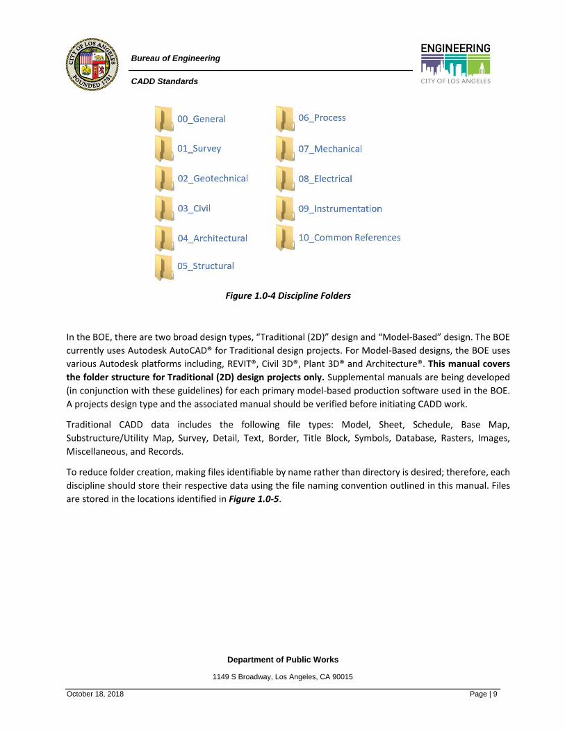
Figure 1.0-4 Discipline Folders
In the BOE, there are two broad design types, “Traditional (2D)” design and “Model-Based” design. The BOE
currently uses Autodesk AutoCAD® for Traditional design projects. For Model-Based designs, the BOE uses
various Autodesk platforms including, REVIT®, Civil 3D®, Plant 3D® and Architecture®. This manual covers
the folder structure for Traditional (2D) design projects only. Supplemental manuals are being developed
(in conjunction with these guidelines) for each primary model-based production software used in the BOE.
A projects design type and the associated manual should be verified before initiating CADD work.
Traditional CADD data includes the following file types: Model, Sheet, Schedule, Base Map,
Substructure/Utility Map, Survey, Detail, Text, Border, Title Block, Symbols, Database, Rasters, Images,
Miscellaneous, and Records.
To reduce folder creation, making files identifiable by name rather than directory is desired; therefore, each
discipline should store their respective data using the file naming convention outlined in this manual. Files
are stored in the locations identified in Figure 1.0-5.

Department of Public Works
1149 S Broadway, Los Angeles, CA 90015
October 18, 2018 Page | 10
Bureau of Engineering
CADD Standards
Figure 1.0-5 Discipline Folder Structure
Most BOE projects include several Disciplines with different folder requirements. The intent of this guideline
is to be comprehensive and flexible. This project folder structure should be considered a minimum
requirement to ensure adequate design data segregation. If a Division, Consultant, or Contractor requires a
project-specific modification or blanket variance from these requirements, it should be approved by the
impacted Division Manager(s), CADD Manager(s) and Design Manager(s) (if applicable) prior.
1.1 File Naming Conventions
Historically the Bureau of Engineering distributed project contract documents via printed paper. The BOE
has since transitioned to distributing contract documents via the digital equivalent, a Portable Document
File (PDF). These files show the same information as printed paper. Elements, however, are readable by
electronic display devices and have increased intelligence.
The universal reading ability of the PDF format has provided new opportunities for Agencies and Contractors
to share, store and update necessary project information more efficiently and sustainably. To maximize this
opportunity and effectively manage vast amounts of data, it is important to have consistent digital file
naming and project folder organization of graphical and non-graphical information. Other benefits include
increased data reuse potential for Designers, Contractors, Operators and Maintenance staff of a facility.

Department of Public Works
1149 S Broadway, Los Angeles, CA 90015
October 18, 2018 Page | 11
Bureau of Engineering
CADD Standards
Before exploring the file naming conventions, we will first discuss the different file types associated with a
typical AutoCAD project.
There are two categories of files. Project files and Library files. The primary difference is that Library files are
used across projects while Project files typically are not. Since the requirements and use for each Bureau
Division’s library varies greatly, each Division is responsible for establishing its individual library standards
within the parameters of these guidelines.
1.1.1 Project File Types Segregating data increases project flexibility and maximizes the number of users able to work concurrently
on a single project. Furthermore, the type of file being created to properly name the file, as this directly
impacts the name, is important to understand. Traditional BOE project data should be segregated according
the following file types: Model, Sheet, Schedule, Base Map, Utility Map, Survey, Detail, Text, Border, Title
Block, Database, Raster, As-Built, Image, Archive, and Miscellaneous. Library file naming conventions are
discussed in a later section. Each file type is defined as follows:
A Model File contains 2D or 3D graphic representation of physical “real-world” items in “real world” scale,
things you would eventually be able to touch in the completed facility. These components are drawn in
"Model Space". Model Files never have a border.
A Sheet File is typically comprised of a border template, text, symbols, notes and views of model files,
representing everything that appears on the final sheet. Sheet Files always have a border.
A Schedule File, unlike Model Files and Sheet Files, may be created by word processing or spreadsheet
software, or may be drawn in CAD or BIM software. In CADD, schedules created in Word, Excel or Access
software are "linked" into a Model or Sheet file for dynamic updating behavior in accordance with the
workflow described in Appendix E 16.2 Linking Schedules to Drawings. This allows a user to revise schedules
outside of the CADD software. If the schedule is not generated by the CADD platform, then it should be
inserted, referenced, linked or embedded to the appropriate sheet file.
A Base Map File is a collection of record data, survey topography and/or imagery that forms the background
setting for a project. The base map typically includes information such as road limits, building footprints,
right of way, easements, primary structures, ground contours, etc. This information is used to provide
background details necessary to orient the project.
A Utility Map File is a collection of utility record data that forms the background setting for existing
underground utilities in a project. The utility map is typically overlayed on a base map file to determine the
existing utility conditions around the project.
A Survey File is typically provided in two files, an AutoCAD .dwg file, which typically includes geolocated
topography, points and features and an .xml file that can be imported into Civil 3D as a Surface and used to

Department of Public Works
1149 S Broadway, Los Angeles, CA 90015
October 18, 2018 Page | 12
Bureau of Engineering
CADD Standards
analyze existing ground conditions. The survey files usually are provided by a third party and should not be
manipulated by the CAD designers. If edits are required due to missing features or poor surface triangulation,
send a correction request to the Surveyor of Record. Survey data supersedes base map information therefore
base maps should be regularly updated to reflect latest survey information.
A Detail File is a specific type of model file that includes plans, elevations, sections, and detail views. A detail
file is required if the view is not derived directly from the project model. They make up the majority of the
individual files in a project folder.
A Text File may be general notes, discipline specific notes, sheet type specific notes (for example, notes that
always apply only to foundation plans), and abbreviations. Word processing software is normally used to
create Text Files.
A Border File contains the surrounding linework that defines the printing area and window limits. The
standard BOE Border file is available for download on the BOE homepage
A Title Block File contains project data and associated gridlines including project location, client, designer,
logos, sheet identification, and sheet management information.
A Database File include tables that define and label "fields" (columns and rows) of data. The process of
creating a table requires that each field be labeled uniquely, and that the allowable kind of data be identified
(for example, whether or not field values must be alphanumeric, text, graphics, calendar dates, integers, real
numbers, etc.). Spreadsheet and database software also lets the creator define valid ranges of values for the
fields.
A Raster File is graphics or a bitmap image representing a generally rectangular grid of pixels, or points of
color. Raster images are stored with image files with varying formats.
An As-Built File is typically a .tif or .pdf file that reflects all changes made in the specifications and working
drawings during the construction process, and are intended to show the exact dimensions, geometry, and
location of all elements of the work completed under the contract. These files are typically downloaded from
the BOE Vault or provided by the Owner of the facility.
An Image File is a file that contains graphics data.
An Archive File is a copy of a file created to record the state of a project for potential reuse in the future. As
each drawing reaches a milestone, it should be copied to the archive folder. Weekly archival backups are
highly recommended. Password restriction to a limited number of qualified people who can responsibly
manage the task is mandatory.
A Miscellaneous File is anything not described above that must be used in the completion of a project.
A Record File is a document that must be kept for evidence, compliance, risk management, etc. related to
CADD.

Department of Public Works
1149 S Broadway, Los Angeles, CA 90015
October 18, 2018 Page | 13
Bureau of Engineering
CADD Standards
1.1.2 Project File Naming For all given projects, Project File naming must be consistent. Consistency in file naming is vital for overall
file and folder management, quicker retrieving and filtering files, and determining the content of a document
to be known without opening the file. Project files as described in section 1.1.1 are to be segregated and
named using the Naming Convention and File Type and Naming Key shown in Figures 1.1.2-1 and 1.1.2-2.
File Type Naming Convention (e.g.)
Model
Sheet
Schedule
Base Map
Utility
Map
Survey
Detail
Text
Border
Title Block
Database
Raster
As Built
Image
Archive
Misc.
Record
Character Field – Project Specific Character Field – Fixed
Figure 1.1.2-1 Naming Convention
Department of Public Works
1149 S Broadway, Los Angeles, CA 90015
October 18, 2018 Page | 14
Bureau of Engineering
CADD Standards
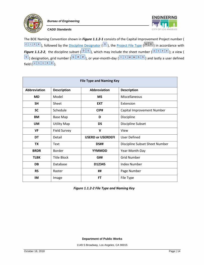
The BOE Naming Convention shown in Figure 1.1.2-1 consists of the Capital Improvement Project number (
), followed by the Discipline Designator ( ), the Project File Type ( ) in accordance with
Figure 1.1.2-2, the discipline subset ( ), which may include the sheet number ( ); a view (
) designation, grid number ( ), or year-month-day ( ) and lastly a user defined
field ( ).
File Type and Naming Key
Abbreviation Description Abbreviation Description
MD Model MS Miscellaneous
SH Sheet EXT Extension
SC Schedule CIP# Capital Improvement Number
BM Base Map D Discipline
UM Utility Map DS Discipline Subset
VF Field Survey V View
DT Detail USERD or USERDEFI User Defined
TX Text DS## Discipline Subset Sheet Number
BRDR Border YYMMDD Year-Month-Day
TLBK Title Block G## Grid Number
DB Database D12345 Index Number
RS Raster ## Page Number
IM Image FT File Type
Figure 1.1.2-2 File Type and Naming Key
Department of Public Works
1149 S Broadway, Los Angeles, CA 90015
October 18, 2018 Page | 15
Bureau of Engineering
CADD Standards
1.2 Library Files
Library files are those used across multiple projects. They can be base maps, imagery, utility map, detail,
schedule, text, database, symbol, border, and title block files. Manufacturers, suppliers, vendors, and all
associated parties who create Library Files for use on multiple projects shall create Library Files in full
compliance with the United States National CAD Standard® drawing and naming conventions. The naming
of these files shall follow either the MasterFormat™ or UniFormat™ file naming method as described below.
Note: Library file types are not project specific.
1.2.1 Library File Types A Schedule file provides project data in a tabulated format. Unlike Model Files and Sheet Files, Schedule Files
may be created by word processing or spreadsheet software.
A Symbol file is a standard graphic representation of an item or materials by association, resemblance, or
convention. A symbol often represents a material or object not fully illustrated on the drawings. They have
a role in creating, understanding, and fulfilling the intent of construction documents. Standard symbols
ensure clear and concise communication among the lead designer, owner, contractor, and consultants.
Refer to section 4.0 Symbols for an explanation of symbol types in detail.
A Block file is a collection of objects that are combined into a single named object.
A Plot Style table file contains several of the plot settings used when plotting a drawing. You can use a table
to reduce the number of redundant steps you need to perform each time you plot a drawing.
Note: Refer to section 1.1.1 for additional file types.
1.2.2 Library File Naming The naming of Library files follows the Bureau’s latest adoption of the Construction Specification Institutes
MasterFormat™. Any outside Consultant or Contractor who creates a Library file for a project should consult
that Division’s standard for Library file naming and be in full compliance. MasterFormat™. A numbering
system based on MasterFormat™ is recommended for naming most library files. Refer to Figure 1.2.2-1. A
numbering system based on UniFormat™ is also acceptable if otherwise multiple MasterFormat™ numbers
are required. If using the MasterFormat™ or Uniformat™ are not appropriate for the library file type, the file
shall be named in accordance with the Project file naming convention.

Department of Public Works
1149 S Broadway, Los Angeles, CA 90015
October 18, 2018 Page | 16
Bureau of Engineering
CADD Standards
Figure 1.2.2-1 Library File Naming
Library Files should not be edited directly for a project. The file should be copied into the project folder and
named according to the project file naming convention. The CADD manager should back up Library files
regularly.
1.3 Sheet Naming Overview
Consistency in labeling and organizing sheets is critical for quality control and predictability of BOE’s Capital
Improvement Project delivery. The Bureau’s sheet identification format adopts the Uniform Drawing System
(UDS) which is a key part of the NCS. The UDS system provides a wide range and flexible identification format
that accommodates all disciplines practiced within the BOE. The system is divided in three main components,
Discipline Designator, Sheet Type designator and the Sheet Sequence number.
1.3.1 Sheet Naming Due to the array of projects completed at the BOE, it has adopted the two-level Discipline designation
system for larger projects consisting of 50 or more sheets. This consists of two unique alphabetical
characters. The first character (Level 1) represents the Licensed Discipline classification. The second
alphabetical character (Level 2) represents the disciplines subject matter, also called “subset”. Refer to
Figure 1.3.1-1. For example, a Civil engineer may be the designer for surface improvements and a storm
water drainage system. With the Level 2 designator system, the Civil engineer will segregate the surface
improvement information onto sheets with the Level 2 designator of CI (Civil Improvements), while the

Department of Public Works
1149 S Broadway, Los Angeles, CA 90015
October 18, 2018 Page | 17
Bureau of Engineering
CADD Standards
storm water drainage system drawings will reside on CU (Civil Utilities) sheets. This method of increased
data segregation is a key part of the system’s flexibility for large projects. Every discipline and associated
subset (Level 2) designators have a unique character value. See 12.0 Appendix A - Sheet Naming & Sheet
Type for a complete list of Disciplines and Discipline Subsets used in the BOE. Projects with less than 50
sheets may opt to omit the Subset (Level 2) designator. The Disciplines are ordered by how they should
appear in the contract documents.
Figure 1.3.1-1 Discipline and Subset
A Sheet Type designator as shown in Figure 1.3.1-3, consists of one unique numerical character that
represents the drawing view type(s) on the sheet (e.g. plan, section, elevation view, etc.). All sheet types
apply to all discipline designators. See Figure 1.3.1-2 for location of the sheet type designator. Refer to
12.0 Appendix A - Sheet Naming & Sheet Type for a list of Sheet Types and Designators. The different
sheet types contain the following type of views:
Figure 1.3.1-2 Sheet Type

Department of Public Works
1149 S Broadway, Los Angeles, CA 90015
October 18, 2018 Page | 18
Bureau of Engineering
CADD Standards
“Sheet File” Types Designators
Sheet Type Designator
General (0): General notes, legends, symbols, keyplans, Title, index, rendering, notices
Plans (1): Views of horizontal planes, showing components in their horizontal
relationship. Plans and Profiles are also included in this sheet type.
Elevations (2):
Views of vertical planes, showing components in their vertical relationship,
viewed perpendicularly from a selected vertical plane. Elevations are views
typically from outside of components and do not show the internal
components not visible from the exterior.
Sections (3): Views of vertical cuts through components, showing their detailed
arrangement.
Large-Scale Views (4):
Plan, elevation, or section drawings reproduced at a larger scale to provide
more detailed information than shown on the smaller-scaled drawing. Scales
1/4”=1’ and larger.
Details (5): Plans, elevations, or sections that provide more specific information about a
portion of a project component or element than smaller-scale drawings.
Schedules (6): Tables or charts that include data about materials, products, and equipment.
Diagrams (6): Non-scaled views showing arrangements of special system components and
connections not possible to clearly show in scaled views.
Photos (7): Non-scaled views not otherwise defined. Aerials, Photographs, Renderings,
etc..
3D Representations &/or
Referenced Attachments (8):
Perspectives, isometric drawings, and electronic CAD models and/or
Reference attachments such as shop drawings, as-builts, schedules, records,
etc..
Figure 1.3.1-3 Sheet Type Designators
Each subset may contain one or more of the preceding sheet types. Using all the sheet types for a project
or within a discipline is not required. Sheet types shall be organized in sequential order. This designator

Department of Public Works
1149 S Broadway, Los Angeles, CA 90015
October 18, 2018 Page | 19
Bureau of Engineering
CADD Standards
does not prevent the combining of sheet types-for instance, a plan and profile or elevation and profile when
required by the design. The lowest sheet value will govern the designation.
The Sheet Sequence number consists of two unique numerical characters that identify each sheet in series
of the same discipline, subset, and sheet type. Refer to Figure 1.3.1-4. Sheet 00 is not allowed. Sequence
numbers need not be sequential to permit future insertion of sheets during design. It is desirable for each
discipline to create their own site plan if work locations differ; for example, sheets AS102, MS102, and
ES102 show the same background site plan but identify their respective work locations.
Figure 1.3.1-4 Sheet Sequence
Additional drawings inserted in a set after a project has been indexed by the vault can use a user-defined
suffix comprised of two characters as shown in Figure 1.3.1-5.
Figure 1.3.1-5 User Defined
Occasionally an entire drawing must be altered and reissued for supplementary work involving a change
in scope. When this occurs, a user-defined suffix character to the sheet identifier may be introduced.
Descriptors include R for revised issues of similar scope, X for complete changes, and A, B, C, for phased
work where multiple versions of the same drawing are expected. A dash always follows the sheet
sequence number to separate it.
Revisions made to drawings after the project is indexed should be indicated by using a revision cloud and
number. The revision number is placed in an upside-down delta next to the revision cloud and
accompanied with a brief description in the revision block.

Department of Public Works
1149 S Broadway, Los Angeles, CA 90015
October 18, 2018 Page | 20
Bureau of Engineering
CADD Standards
2.0 Sheet Organization
This section provides guidelines for management and organization of sheets. The benefits of sheet
organization standards include: enhanced communication among drawing preparers and users, improved
quality control by providing a quality assurance standard. Easier data management and consistent sheet
format among design disciplines, conveying a coordinated message to bidders.
2.1 Sheet Size
The Bureau of Engineering primarily issues documents digitally. Regardless if the document is issued via
hard copy or digital, the plotted size should be Architectural Size D (24” x 36”). Change Order and/or
Supplemental drawings are typically issued on ANSI Size B 11x17 sheets.
2.2 Sheet Layout
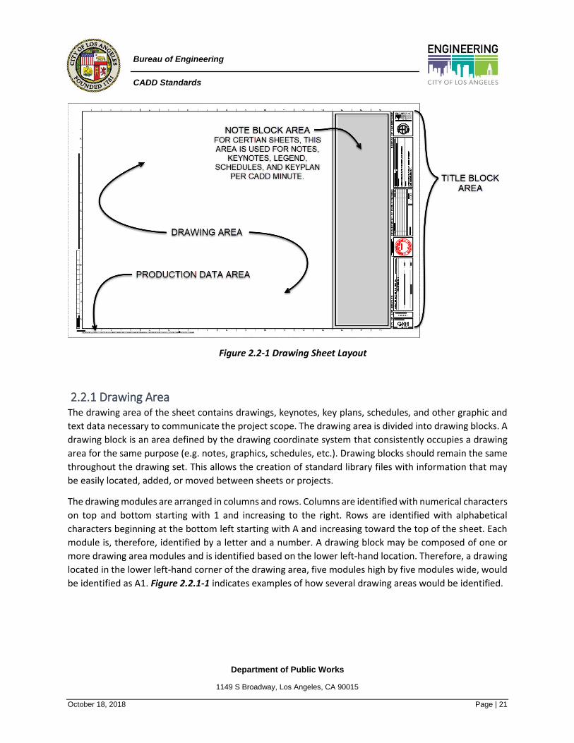
Drawing sheets are primarily divided into four main areas: drawing area, title block area, production data
area, and note block area as shown in Figure 2.2-1 below.
The first three areas are required on every drawing. These areas contain information regarding
construction or reference information, project management or presentation information, and project
production information. These areas are defined by a border to clearly separate them from each other.
The last area, Note Block Area, is the area within the drawing area where keynotes, sheet notes, schedules,
legends, and key plans are located.
Sheet margins are the space between the edge of the sheet and the sheet area and are predefined in the
BOE template Border files available on the BOE’s website.
Department of Public Works
1149 S Broadway, Los Angeles, CA 90015
October 18, 2018 Page | 21
Bureau of Engineering
CADD Standards
Figure 2.2-1 Drawing Sheet Layout
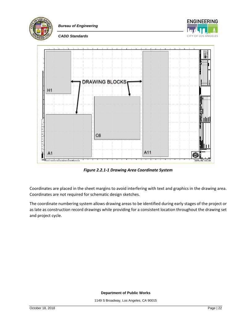
2.2.1 Drawing Area The drawing area of the sheet contains drawings, keynotes, key plans, schedules, and other graphic and
text data necessary to communicate the project scope. The drawing area is divided into drawing blocks. A
drawing block is an area defined by the drawing coordinate system that consistently occupies a drawing
area for the same purpose (e.g. notes, graphics, schedules, etc.). Drawing blocks should remain the same
throughout the drawing set. This allows the creation of standard library files with information that may
be easily located, added, or moved between sheets or projects.
The drawing modules are arranged in columns and rows. Columns are identified with numerical characters
on top and bottom starting with 1 and increasing to the right. Rows are identified with alphabetical
characters beginning at the bottom left starting with A and increasing toward the top of the sheet. Each
module is, therefore, identified by a letter and a number. A drawing block may be composed of one or
more drawing area modules and is identified based on the lower left-hand location. Therefore, a drawing
located in the lower left-hand corner of the drawing area, five modules high by five modules wide, would
be identified as A1. Figure 2.2.1-1 indicates examples of how several drawing areas would be identified.
Department of Public Works
1149 S Broadway, Los Angeles, CA 90015
October 18, 2018 Page | 22
Bureau of Engineering
CADD Standards
Figure 2.2.1-1 Drawing Area Coordinate System
Coordinates are placed in the sheet margins to avoid interfering with text and graphics in the drawing area.
Coordinates are not required for schematic design sketches.
The coordinate numbering system allows drawing areas to be identified during early stages of the project or
as late as construction record drawings while providing for a consistent location throughout the drawing set
and project cycle.

Department of Public Works
1149 S Broadway, Los Angeles, CA 90015
October 18, 2018 Page | 23
Bureau of Engineering
CADD Standards
2.2.2 Title Block Area The title block area of the sheet area is that portion of the sheet
containing project, client, designer, sheet identification, and sheet
management information needed by the user of the sheet. Refer
to Figure 2.2.2-1. The guidelines for the title block area provide criteria
for the location of like information shown in data blocks within the title
block area for easy and consistent retrieval and filing of drawings.
Designer and Engineer should pay attention to every field in the title
block.
Figure 2.2.2-1 Title Block Area
2.2.3 Production Data Area The production data area is a portion of the sheet that contains information on the production of the sheet.
This data is located along the bottom in the lower left corner of the sheet and may include the file path, print
time stamp, design revision date, etc. Refer to Figure 2.2.3-1.
Figure 2.2.3-1 Production Data Area
Department of Public Works
1149 S Broadway, Los Angeles, CA 90015
October 18, 2018 Page | 24
Bureau of Engineering
CADD Standards
2.2.4 Note Area Not all sheets will have a note block. The note block is located in the far-right column of the drawing area.
Refer to Figure 2.2-1 and 12.2 Appendix A – Sheet Naming & Sheet Type for additional details.
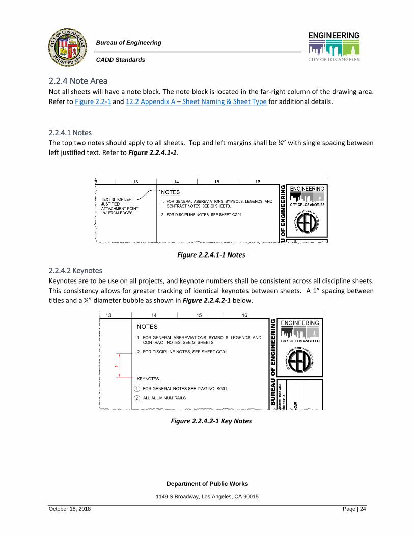
2.2.4.1 Notes The top two notes should apply to all sheets. Top and left margins shall be ¼” with single spacing between
left justified text. Refer to Figure 2.2.4.1-1.
Figure 2.2.4.1-1 Notes
2.2.4.2 Keynotes Keynotes are to be use on all projects, and keynote numbers shall be consistent across all discipline sheets.
This consistency allows for greater tracking of identical keynotes between sheets. A 1” spacing between
titles and a ¼” diameter bubble as shown in Figure 2.2.4.2-1 below.
Figure 2.2.4.2-1 Key Notes

Department of Public Works
1149 S Broadway, Los Angeles, CA 90015
October 18, 2018 Page | 25
Bureau of Engineering
CADD Standards
2.2.4.3 Key Plan A key plan block, when used, should always be located
in the lowest module of the note block. Refer
to Figure 2.2.4.3-1.
Figure 2.2.4.3-1 Key Plan
2.2.5 Cover Sheet The cover sheet, available on the BOE website, may identify the project, owner, and other project team
members involved in preparing the drawings as shown in Figure 2.2.5-1. The cover sheet may also contain a
photograph, rendering of the project, or Key Plan on smaller projects consisting of 10 or less sheets.
If the cover sheet contains specific project data such as a list of sheets, a listing of abbreviations, general
notes, a building code summary, or a key plan, etc., it should be identified with a sheet identifier containing
the discipline designator G for general, sheet type 0, and the sequence number 01 (G-001). Refer to 11.0
Appendix A – Sheet Naming & Sheet Type for further explanation of the sheet identification format.
Figure 2.2.5-1 Cover Sheet

Department of Public Works
1149 S Broadway, Los Angeles, CA 90015
October 18, 2018 Page | 26
Bureau of Engineering
CADD Standards
2.3 Supplemental Sheets
The supplemental drawing sheet format is similar to the standard sheet format but is used for supplemental
drawing sheets. Refer to Figure 2.3-1 for an example of a supplemental drawing sheet.
Figure 2.3-1 Supplemental drawing sheet
Department of Public Works
1149 S Broadway, Los Angeles, CA 90015
October 18, 2018 Page | 27
Bureau of Engineering
CADD Standards
3.0 Drawing Conventions
The Drafting Conventions Section provides a standard format for both graphic and textual information within
drawings. This section provides the following:
• Standards for information consistent with computer-aided drafting (CADD & design)
• Guidelines for consistent placement of drawings information on the sheet
• Guidelines for consistent orientation of dimensions related to drawings
• Line values
• A consistent method of using scales
• A system for creating a mock-up set at the commencement of the project
The Drafting Conventions Section sets a clear, concise, comprehensive, and consistent standard for
facilitating cross-referencing, retrieving information, and communicating clearly for drawing creators and
users.
3.1 Drawing Standards
Drawing standards provide uniform guidelines for producing a set of construction drawings of consistent
quality that eliminates duplication of information. These standards address the placement of the drawing
grid and north arrow, recommended scales, type of lines, and symbols used to represent different articles in
the drawings, the way to represent different materials graphically and the use of notations.
Plans are the basis of drawing documentation. From these, enlarged plans, elevations, sections, and details
are developed through a two-way flow of information between the user and the computer. When a change
occurs in referenced drawings, it can trigger changes in the other drawings. The order of information to be
shown on a sheet layout is detailed in section 2.3 Drawing Sheet Layout.
Note: All standards described in this section are available on the BOE website for download.
3.1.1 Drawing Orientation & North Arrow Three types of north arrows exist: true north, magnetic north, and project north. True north points to the
North Pole, and magnetic north is a compass point deviating slightly from true north and project north
provides a reference point parallel to the plan grid. Magnetic north is rarely indicated and should be
combined with true north unless the project is near the North Pole. Refer to Figure 3.1.1-1.

Department of Public Works
1149 S Broadway, Los Angeles, CA 90015
October 18, 2018 Page | 28
Bureau of Engineering
CADD Standards
Figure 3.1.1-1 Diagrammatic illustration of north arrow.
Plans may be oriented on a sheet in various ways to display the requirements of the project and the intent
of the designer. The orientation of a building's main floor plan or project site plan sets up the orientation of
all succeeding views. Ideally, the entire project area floor plan should be shown on one sheet. If it cannot fit
on one sheet, the plan should be subdivided into convenient segments with match lines provided to
reference where the plan is continued. Refer to section 3.1.7.7 Matchlines.
Civil plans may orient the drawing in a manner that will allow the site plan to fit within the sheet boundary
when drawn at the most appropriate scale. Refer to Figure 3.1.1-2. It is required to orient the site plan in
the same manner as other plan views.
Figure 3.1.1-2 Sheet layout orientation

Department of Public Works
1149 S Broadway, Los Angeles, CA 90015
October 18, 2018 Page | 29
Bureau of Engineering
CADD Standards
The most common orientation of floor or site plans is one where the plan north arrow points to the top of
the drawing block. The true north arrow is adjusted so that the building grid and project north arrow are
parallel to the sheet orientation. This approach follows the customary orientation for maps.
The graphic depiction of the north arrow indicator symbol and the orientation of the project north arrow, if
different, shall only be rotated between 0° and 180°, is to be shown on all plan views, and should remain
consistent throughout the set of drawings. Plan north enables the designer to assign simple names to interior
and exterior elevations. Figure 3.1.1-3 displays the required north arrow indicator symbol.
North Arrow
Figure 3.1.1-3 North Arrow
Place the north arrow and scale bar in the bottom right-hand corner of the drawing area. Refer
to Figure 3.1.1-4. The Scale Bar shall be placed 0.5” directly below the North Arrow and is to be shown on
all plan views. If more than one plan view is shown on a sheet, then the scale is indicated in the view title
with no scale bar. When true north or plan north are indicated with separate symbols, place them in the
bottom right-hand corner of the drawing block, located above the drawing block title symbol.
NORTH ARROW AND
SCALE BAR LOCATION
Figure 3.1.1-4 North Arrow & Scale Bar Location

Department of Public Works
1149 S Broadway, Los Angeles, CA 90015
October 18, 2018 Page | 30
Bureau of Engineering
CADD Standards
In large or multistory projects, a sheet containing small scale plans for all levels or areas drawn at 1”100,
1:200, or 1:500 (1/8”, 1/16", or 1/32" = 1'-0") scale or smaller may be included in the set to provide an
overview of the project and serve as a quick reference. This sheet is useful if the floor or site plan is divided
into segments to fit in a standard size sheet. It is also useful if the project will be constructed in phases.
Consistency of the display of information throughout the set is important. For example, a foundation plan
detail should be shown in the same orientation as it is shown on the floor plan. Refer to Figure 3.1.1-5. An
enlarged section detail should also have the same orientation as the wall section or building section from
which it is derived.
Figure 3.1.1-5 Plan detail having the same orientation as the floor plan.

Department of Public Works
1149 S Broadway, Los Angeles, CA 90015
October 18, 2018 Page | 31
Bureau of Engineering
CADD Standards
3.1.2 Grid System A grid system is used to indicate structural columns, load-bearing walls, shear walls, and other structural
elements on drawings. It is used primarily for reference in schedules of data. A grid system is also used if the
design of a building or structure is based on a module system, regardless of the structural system. Grid lines
are used as a basis for dimensioning. Proper planning and layout of a drawing on the selected sheet size
requires the accommodation of alphanumeric grid designations within column indicators. Vertical grid lines
should have designators at the top of the grid numbered from left to right. Horizontal grid lines should have
designators at the right side of the grid alphabetized from bottom to top. To eliminate confusion with the
numerals 0 (zero) and 1 (one), do not use letters O or I.
Grid line and indicator formats should conform to the graphic guidelines under Reference Symbols in
the Symbols Module. In some cases, column indicators may be shown at both ends of the grid line to
facilitate reference, especially if a modular grid system is used.
Figure 3.1.2-1 Illustration of column grid line.
Where additional intermediate structural support elements occur between grid lines, a fractional
designation is used. For example, a column occurring at mid-point between grid lines 2 and 3 would be
designated 2.5. In a similar manner, columns occurring between grid lines A and B would be represented as
A.1, A.2, A.3, and A.4. Refer to Figure 3.1.2-1. While the structural drawings must maintain the grid line
number as long as the column is located under the floor, architectural drawings omit the indicator at the
level where the column ceases to exist. For example, if a building steps back as its height rises, unused
columns and their associated grid marks are not shown on the architectural plans. Structural drawings will
show them because columns below are supporting the floor.
Department of Public Works
1149 S Broadway, Los Angeles, CA 90015
October 18, 2018 Page | 32
Bureau of Engineering
CADD Standards
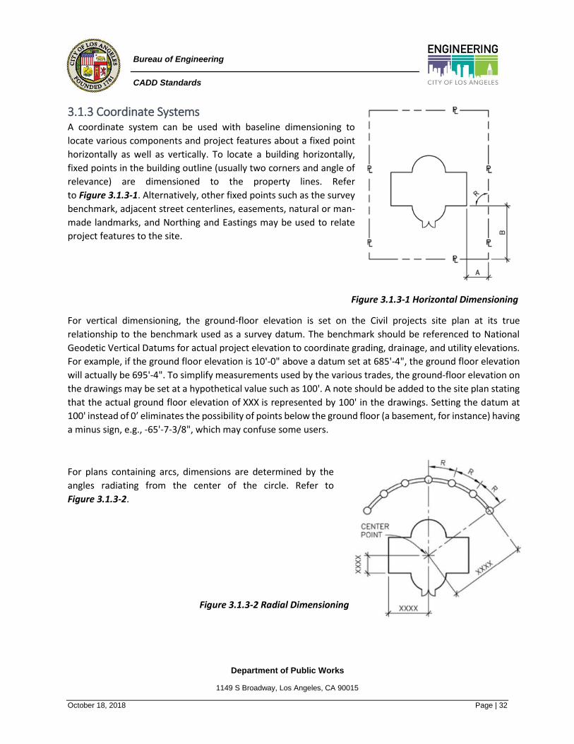
3.1.3 Coordinate Systems A coordinate system can be used with baseline dimensioning to
locate various components and project features about a fixed point
horizontally as well as vertically. To locate a building horizontally,
fixed points in the building outline (usually two corners and angle of
relevance) are dimensioned to the property lines. Refer
to Figure 3.1.3-1. Alternatively, other fixed points such as the survey
benchmark, adjacent street centerlines, easements, natural or man-
made landmarks, and Northing and Eastings may be used to relate
project features to the site.
Figure 3.1.3-1 Horizontal Dimensioning
For vertical dimensioning, the ground-floor elevation is set on the Civil projects site plan at its true
relationship to the benchmark used as a survey datum. The benchmark should be referenced to National
Geodetic Vertical Datums for actual project elevation to coordinate grading, drainage, and utility elevations.
For example, if the ground floor elevation is 10'-0" above a datum set at 685'-4", the ground floor elevation
will actually be 695'-4". To simplify measurements used by the various trades, the ground-floor elevation on
the drawings may be set at a hypothetical value such as 100'. A note should be added to the site plan stating
that the actual ground floor elevation of XXX is represented by 100' in the drawings. Setting the datum at
100' instead of 0’ eliminates the possibility of points below the ground floor (a basement, for instance) having
a minus sign, e.g., -65'-7-3/8", which may confuse some users.
For plans containing arcs, dimensions are determined by the
angles radiating from the center of the circle. Refer to
Figure 3.1.3-2.
Figure 3.1.3-2 Radial Dimensioning

Department of Public Works
1149 S Broadway, Los Angeles, CA 90015
October 18, 2018 Page | 33
Bureau of Engineering
CADD Standards
3.1.4 Drafting Precision Pen- or pencil-generated drawings are only as accurate as the thickness of the instrument's point and the
person using these tools. CAD-generated drawings, in contrast, can be absolutely accurate. Various people
throughout the design, construction, and post-construction phases use these drawings. In-house staff,
consultants, contractors, owners, and tenants need to rely on the accuracy.
To prevent drawings from becoming illegible, eliminate over-detailing drawings unless a drawing is
specifically being done for a purpose. For example, a steel stud thickness may be represented by a double
line. Should these studs be drawn at 16" on center in a floor plan, the result would be a tremendous amount
of useless data. This level of drafting detail is unnecessary and must be avoided.
The following points should be considered when creating any drawing:
• Drawings do not always have to be abstract. The purpose and level-of-detail should be determined
at the beginning of the project.
• Use the minimum number of lines possible to represent an object.
• Drawings should be large enough to be of appropriate size when plotted. Show only the amount of
detail necessary for legibility when plotted at its intended scale.
• If an area of a drawing is to be enlarged when referenced/linked to another drawing, limit the
amount of unrelated information shown for a specific area and detail that will be enlarged.
• Eliminate time consuming useless data.
Ensure that lines join precisely at their ends. Do not allow them to overlap or fall short. Lines that do not
meet precisely will end up causing errors when other items that rely on the precision of the intersections are
created or inserted.
Use precise dimensions in Schematic Design Drawings when they are to be converted into Design
Development and Construction Documents Drawings. Refer to Figure 3.1.5.2-1 for discipline-specific
Standard Units and required precision. If Schematic Design Drawings are not intended for use in subsequent
phases, nominal dimensions may be used. In either case, a note informing the reader of the dimensioning
method used should be included in the project notes. For instance, modular dimensions are used for items
such as masonry units where the thickness of the joint is included with the length of the masonry unit.
It is highly recommended that the actual dimensions or coordinates of a specific point in space be typed or
use identifiable points such as the intersection of two lines when drawing, copying, moving, offsetting, or
inserting items vs. using the X and Y coordinates displayed on the monitor.
Department of Public Works
1149 S Broadway, Los Angeles, CA 90015
October 18, 2018 Page | 34
Bureau of Engineering
CADD Standards
3.1.5 Scales & Units Scale is the ratio of measuring units expressing a proportional relationship between a printed drawing sheet
and the full-size item it represents. In CAD, drawings are created at full scale and plotted at the selected
scale.
3.1.5.1 Scales Manual drafting requires a scale to represent large objects, assemblies, and buildings on a relatively small
sheet. CAD permits the user to work directly with a full-size model of the building to be constructed.
Graphic elements within the drawings such as notes, leaders, dimensions, and reference bubbles are drawn
in Paper Space and are always the same size. However, occasionally there are exceptions that involve certain
design data that is drawn in Model space. The size of this design data must be sized according to the scale
of the final plot. Depending on the discipline and on the type of drawing, specific drawing scales need to be
used. Refer to Figure 3.1.5.1-1 for a breakdown of these requirements.
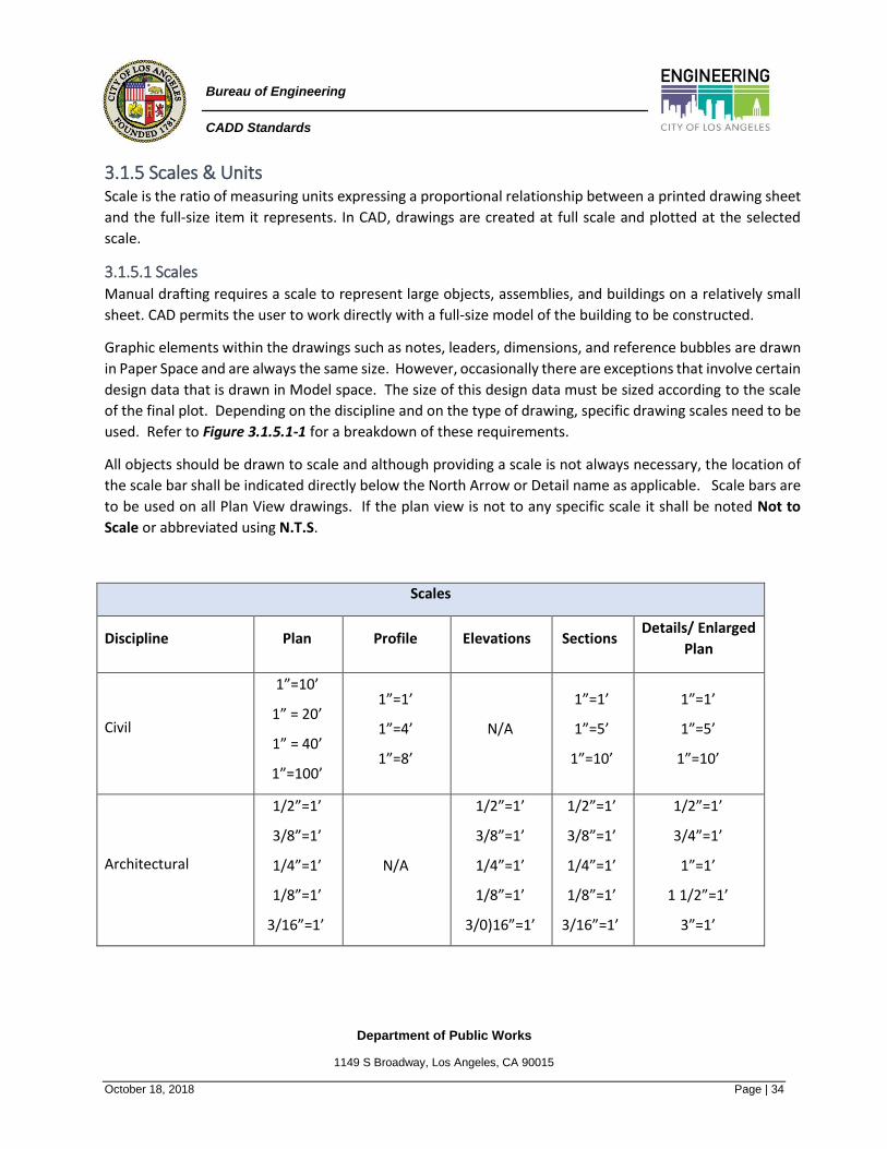
All objects should be drawn to scale and although providing a scale is not always necessary, the location of
the scale bar shall be indicated directly below the North Arrow or Detail name as applicable. Scale bars are
to be used on all Plan View drawings. If the plan view is not to any specific scale it shall be noted Not to
Scale or abbreviated using N.T.S.
Scales
Discipline Plan Profile Elevations Sections Details/ Enlarged
Plan
Civil
1”=10’
1” = 20’
1” = 40’
1”=100’
1”=1’
1”=4’
1”=8’
N/A
1”=1’
1”=5’
1”=10’
1”=1’
1”=5’
1”=10’
Architectural
1/2”=1’
3/8”=1’
1/4”=1’
1/8”=1’
3/16”=1’
N/A
1/2”=1’
3/8”=1’
1/4”=1’
1/8”=1’
3/0)16”=1’
1/2”=1’
3/8”=1’
1/4”=1’
1/8”=1’
3/16”=1’
1/2”=1’
3/4”=1’
1”=1’
1 1/2”=1’
3”=1’

Department of Public Works
1149 S Broadway, Los Angeles, CA 90015
October 18, 2018 Page | 35
Bureau of Engineering
CADD Standards
Structural
1/2”=1’
3/8”=1’
1/4”=1’
1/8”=1’
3/16”=1’
N/A
1/2”=1’
3/8”=1’
1/4”=1’
1/8”=1’
3/16”=1’
1/2”=1’
3/8”=1’
1/4”=1’
1/8”=1’
3/16”=1’
1/2”=1’
3/4”=1’
1”=1’
1 1/2”=1’
3”=1’
Mechanical
1/8”=1’ 1/4”=1’
3/8”=1’
N/A
1/4”=1’
3/8”=1’
1/2”=1’
1/4”=1’
3/8”=1’
1/2”=1’
1/2”=1’
3/4”=1’
1”=1’
1.5”=1’
3”=1’
Electrical
1/2”=1’
1/4”=1’
1/8”=1’
1/16”=1’
3/32=1’
N/A 1/2”=1’
1/4”=1’ N/A
1/2”=1’
1/4”=1’
Instrumentation &
Control
1/2”=1’
1/4”=1’
1/8”=1’
1/16”=1’
3/32=1’
N/A 1/2”=1’
1/4”=1’ N/A
1/2”=1’
1/4”=1’
Figure 3.1.5.1-1 Scales
Department of Public Works
1149 S Broadway, Los Angeles, CA 90015
October 18, 2018 Page | 36
Bureau of Engineering
CADD Standards
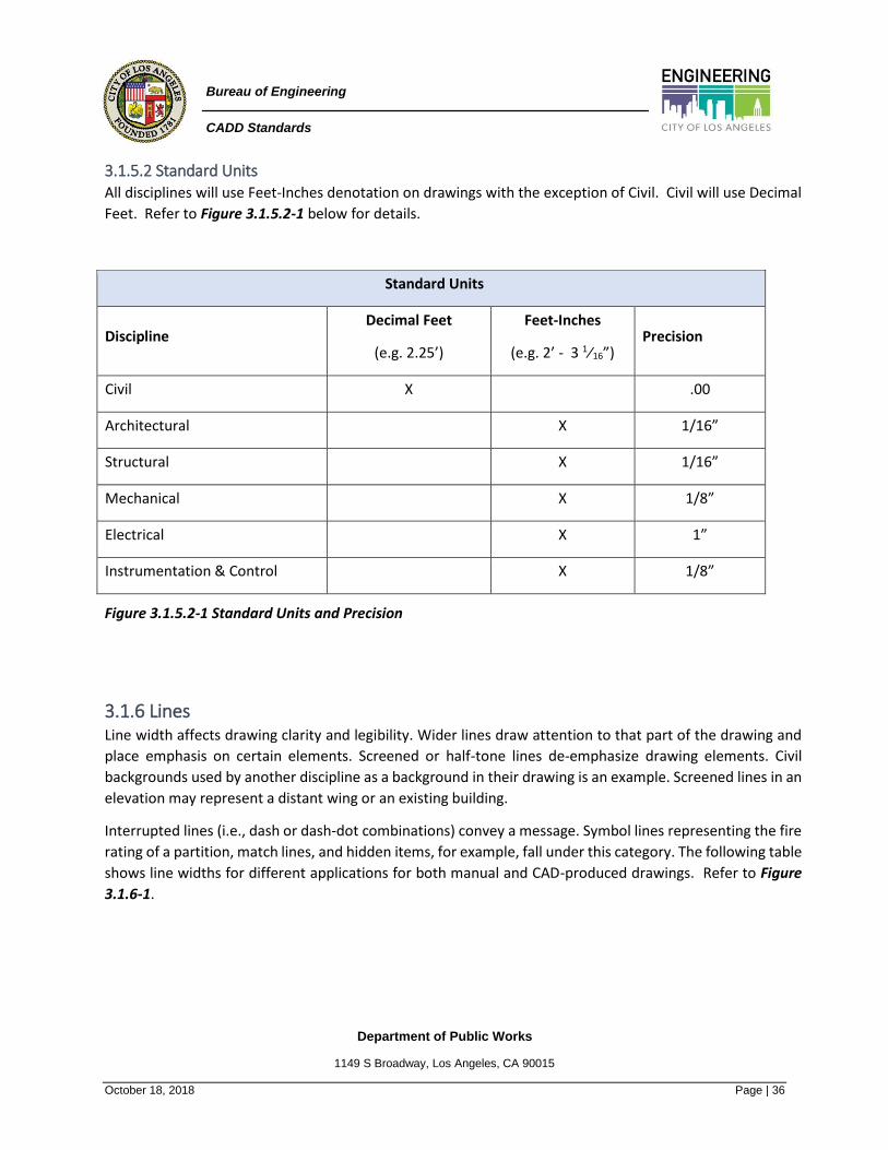
3.1.5.2 Standard Units All disciplines will use Feet-Inches denotation on drawings with the exception of Civil. Civil will use Decimal
Feet. Refer to Figure 3.1.5.2-1 below for details.
Standard Units
Discipline Decimal Feet
(e.g. 2.25’)
Feet-Inches
(e.g. 2’ - 3 1⁄16”) Precision
Civil X .00
Architectural X 1/16”
Structural X 1/16”
Mechanical X 1/8”
Electrical X 1”
Instrumentation & Control X 1/8”
Figure 3.1.5.2-1 Standard Units and Precision
3.1.6 Lines Line width affects drawing clarity and legibility. Wider lines draw attention to that part of the drawing and
place emphasis on certain elements. Screened or half-tone lines de-emphasize drawing elements. Civil
backgrounds used by another discipline as a background in their drawing is an example. Screened lines in an
elevation may represent a distant wing or an existing building.
Interrupted lines (i.e., dash or dash-dot combinations) convey a message. Symbol lines representing the fire
rating of a partition, match lines, and hidden items, for example, fall under this category. The following table
shows line widths for different applications for both manual and CAD-produced drawings. Refer to Figure
3.1.6-1.

Department of Public Works
1149 S Broadway, Los Angeles, CA 90015
October 18, 2018 Page | 37
Bureau of Engineering
CADD Standards
Line Weights
Name Appearance Thickness
Use mm in
Extra Fine 0.13 0.005
Fine detail which cannot be accomplished
using a fine (0.18 mm / 0.007 in) line. Hatch
lines and patterns, MEP centerlines
Fine 0.18 0.007 Material indications, surface marks, Xrefs,
backgrounds and schedule grid lines
Thin 0.25 0.010
Dimension lines, leaders, extension lines,
break lines, hidden objects, dashed lines,
center lines, grid lines and existing
schematic symbols
Medium 0.35 0.014
Object lines, text, lettering, terminator
marks, door and window elevations and
schedule grid accent lines
Wide 0.50 0.020
Titles, property lines, minor title underlines,
edges of interior and exterior elevations,
footprints, profiling, section cut lines,
section cutting, plane lines, drawing block
borders, legend hatch outlines and new
schematic symbols
Extra Wide 0.70 0.028
Match lines, setbacks, large titles, objects
requiring special emphasis, sheet borders
and schedule outlines
XX Wide 1.00 0.039 Major title underlining and separating
portions of design
XXX Wide 1.40 0.055 Right of way and cover sheet lines
XXXX Wide 2.00 0.079 Cover sheet lines
Figure 3.1.6-1 Standard Lines and Line weights
Department of Public Works
1149 S Broadway, Los Angeles, CA 90015
October 18, 2018 Page | 38
Bureau of Engineering
CADD Standards
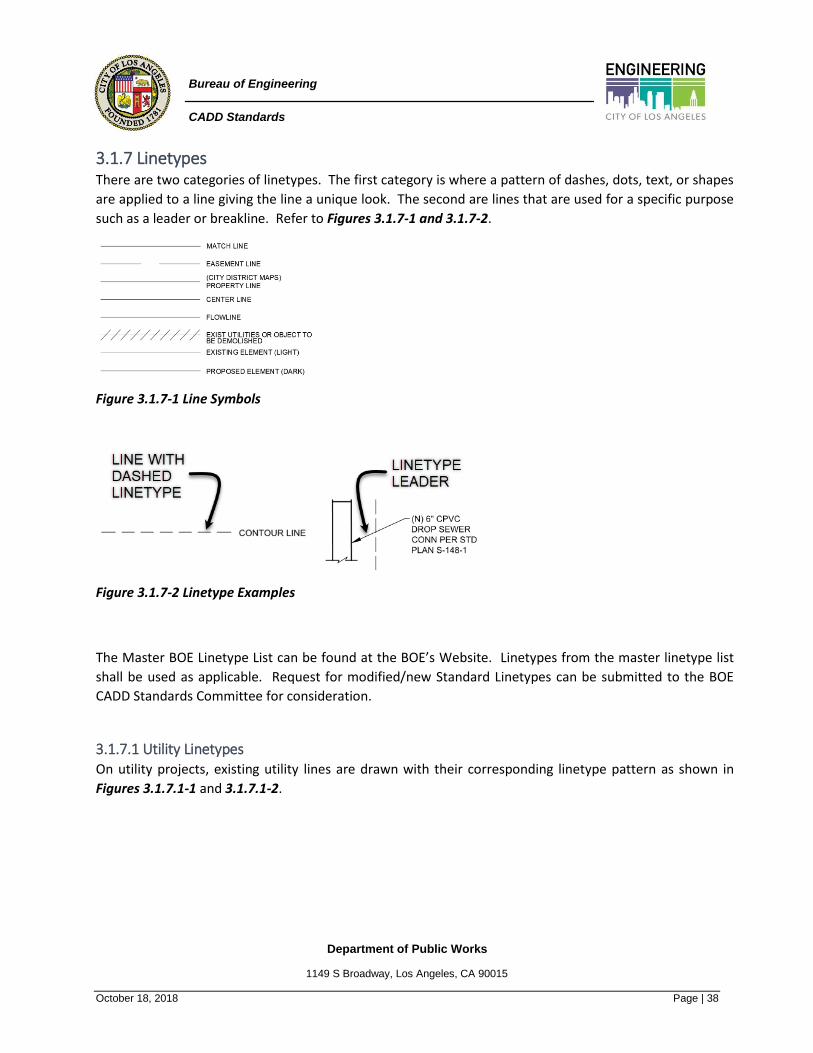
3.1.7 Linetypes There are two categories of linetypes. The first category is where a pattern of dashes, dots, text, or shapes
are applied to a line giving the line a unique look. The second are lines that are used for a specific purpose
such as a leader or breakline. Refer to Figures 3.1.7-1 and 3.1.7-2.
Figure 3.1.7-1 Line Symbols
Figure 3.1.7-2 Linetype Examples
The Master BOE Linetype List can be found at the BOE’s Website. Linetypes from the master linetype list
shall be used as applicable. Request for modified/new Standard Linetypes can be submitted to the BOE
CADD Standards Committee for consideration.
3.1.7.1 Utility Linetypes On utility projects, existing utility lines are drawn with their corresponding linetype pattern as shown in
Figures 3.1.7.1-1 and 3.1.7.1-2.

Department of Public Works
1149 S Broadway, Los Angeles, CA 90015
October 18, 2018 Page | 39
Bureau of Engineering
CADD Standards
Figure 3.1.7.1-1 Utility Linetypes

Department of Public Works
1149 S Broadway, Los Angeles, CA 90015
October 18, 2018 Page | 40
Bureau of Engineering
CADD Standards
Utility Linetypes Continued:
Figure 3.1.7.1-2 Utility Linetypes

Department of Public Works
1149 S Broadway, Los Angeles, CA 90015
October 18, 2018 Page | 41
Bureau of Engineering
CADD Standards
3.1.7.2 Leaders Lines that connect notes, dimensions, or symbols to a point or item in a drawing. Leaders terminate with an
arrowhead terminating on the item being described by the notation. When creating leaders, they should be
drawn straight. Curved leaders are not allowed. To improve readability and minimize confusion with other
lines, leaders should be angled at approximately 45 degrees from horizontal. Leaders shall not cross
dimension lines or each other. Crossing drawing elements should be avoided. Leaders should start at the
upper right side or upper left side of the notation. Refer to Figure 3.1.7.2-1.
Figure 3.1.7.2-1 Leader Styles and Text
3.1.7.3 Breaklines Breaklines are used to indicate the cut between two parts or levels. Examples include a drawing
foreshortened to fit into a detail block or an inclined plane such as a stair or parking ramp connected between
two floors. Breaklines shall be centered on object. Drawing objects shall not cross breaklines. Never
foreshorten parts of the drawing that require detailing. Refer to Figure 3.1.7.3-1.
Figure 3.1.7.3-1 Breaklines
Recommended workflow for breakline creation in AutoCAD and AutoCAD based products is to use the
Dimension Jog line command as described in section 3.1.7.3.1 Dimension Jog Line, or the Express Tools
Break-line Symbol as described in section 3.1.7.3.2 Break-Line Symbol.
Department of Public Works
1149 S Broadway, Los Angeles, CA 90015
October 18, 2018 Page | 42
Bureau of Engineering
CADD Standards
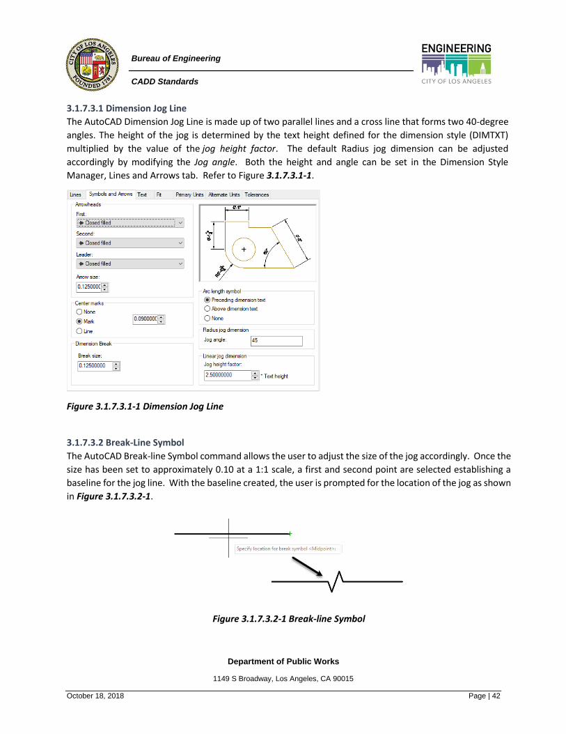
3.1.7.3.1 Dimension Jog Line
The AutoCAD Dimension Jog Line is made up of two parallel lines and a cross line that forms two 40-degree
angles. The height of the jog is determined by the text height defined for the dimension style (DIMTXT)
multiplied by the value of the jog height factor. The default Radius jog dimension can be adjusted
accordingly by modifying the Jog angle. Both the height and angle can be set in the Dimension Style
Manager, Lines and Arrows tab. Refer to Figure 3.1.7.3.1-1.
Figure 3.1.7.3.1-1 Dimension Jog Line
3.1.7.3.2 Break-Line Symbol
The AutoCAD Break-line Symbol command allows the user to adjust the size of the jog accordingly. Once the
size has been set to approximately 0.10 at a 1:1 scale, a first and second point are selected establishing a
baseline for the jog line. With the baseline created, the user is prompted for the location of the jog as shown
in Figure 3.1.7.3.2-1.
Figure 3.1.7.3.2-1 Break-line Symbol

Department of Public Works
1149 S Broadway, Los Angeles, CA 90015
October 18, 2018 Page | 43
Bureau of Engineering
CADD Standards
3.1.7.4 Centerlines Centerlines are used to indicate the center of a column, wall, pipe, roadway, etc. A thin line interrupted at
intervals of a short dash represents centerlines.
Recommended workflow for centerline creation in AutoCAD and AutoCAD-based
products is to use the centerline tools located in the Annotate ribbon.
3.1.7.5 Dimension Lines Dimension Lines are represented by a thin line connecting between extension lines defining the beginning
and end of the object being dimensioned. A terminator mark identifies the intersection between an
extension line and a dimension line. Terminator marks should be angled consistently in the same direction.
Refer to Figure 3.1.7.5-1 below.
Figure 3.1.7.5-1 Dimensioning
Dimension, extension and leader lines shall not cross each other unless unavoidable. When it is
unavoidable, a dimension line is never broken except for inserting the dimension. An extension or leader
line shall neither run through a dimension nor shall they be broken except where they pass through or
adjacent to arrowheads.
Dimensions should never be exploded. Use prefix, suffix, and override feature to add desired values.
Dimension views that most clearly show the form of the feature. Sufficient dimensions shall be shown to
clearly define size, shape, and position of each feature. A feature shall not be located by more than one
tolerance dimension in any one direction.
Unless clarity is improved, dimensions are shown outside the outline of the feature. Each dimension shall
be expressed so that it can be interpreted in only one way. Object lines or extension lines should not be
used as dimension lines. Do not dimension to hidden lines. Staggered dimensions shall be used to prevent
interference with other dimensions. Diametrical and radial dimensions shall be specified with symbols.
The recommended dimension style EED Annotative is available in the BOE drawing template.

Department of Public Works
1149 S Broadway, Los Angeles, CA 90015
October 18, 2018 Page | 44
Bureau of Engineering
CADD Standards
3.1.7.6 Matchlines Matchlines, as mentioned in section 3.1.1 Drawing Orientation & North Arrow, delineate division between
two or more areas of a continuous structure that must be shown on separate sheets because of sheet size
limitations. Do not locate matchlines on column lines, grid lines, or expansion joints. Locate them instead at
the centerline of a wall or corridor. Matchlines shall be centered on the drawing object and should be shown
at the same location on both sheets containing adjacent segments of the plan at the same location. A portion
of plan overlap should be shown beyond the matchline to establish the relationship between adjacent plan
segments. This overlapped portion must be lightly shaded to avoid duplication during cost estimating. They
may jog to avoid important elements of the plan. All matchlines should be shown on the Key plan. The line
width for match lines is indicted in Figure 3.1.7.6-1 below.
Figure 3.1.7.6-1 Matchlines
The recommended linetype Match Line is available in the BOE drawing template as shown in Figure 3.1.7.6-
2.
Match Line
Figure 3.1.7.6-2 Matchlines

Department of Public Works
1149 S Broadway, Los Angeles, CA 90015
October 18, 2018 Page | 45
Bureau of Engineering
CADD Standards
3.1.7.7 Hidden Lines Hidden Lines represent items obscured from view by another material. Examples include steel lintels,
relieving angles in elevations, and items above or below a floor plan. Thin dashed lines represent hidden
lines as shown in Figure 3.1.7.7-1.
Figure 3.1.7.7-1 Hidden lines
The recommended hidden linetype style HIDDEN is available in the BOE drawing template. Refer to Figure
3.1.7.7-2.
Hidden Lines
Figure 3.1.7.7-2 Hidden Lines
3.1.7.8 Property Lines Property Lines are represented by a line interrupted by double dashes as shown in Figure 3.1.7.8-1. They
indicate the boundary of the site.
Property Lines
Figure 3.1.7.8-1 Property Lines
The recommended property linetype style Continuous is available in the BOE drawing template.

Department of Public Works
1149 S Broadway, Los Angeles, CA 90015
October 18, 2018 Page | 46
Bureau of Engineering
CADD Standards
3.1.8 Dimensions Dimensioning is defined as the act of incorporating numerical values into a drawing as a means of sizing
various components and locating elements of a project. Dimensions must be accurate and adequate.
Inadequate dimensions require clarifications during construction, possible loss of time, and errors.
The purpose of dimensioning is to locate each element of the construction. Each wall or part of a detail must
be tied to a fixed point such as a column centerline or an existing benchmark. This applies to plans and the
enlargements associated with them. Refer to Figures 3.1.8-1 and 3.1.8-2.
Care must be taken to show a single dimension only once in its proper location. Avoid the tendency to over-
dimension.
Figure 3.1.8-1 Dimensions
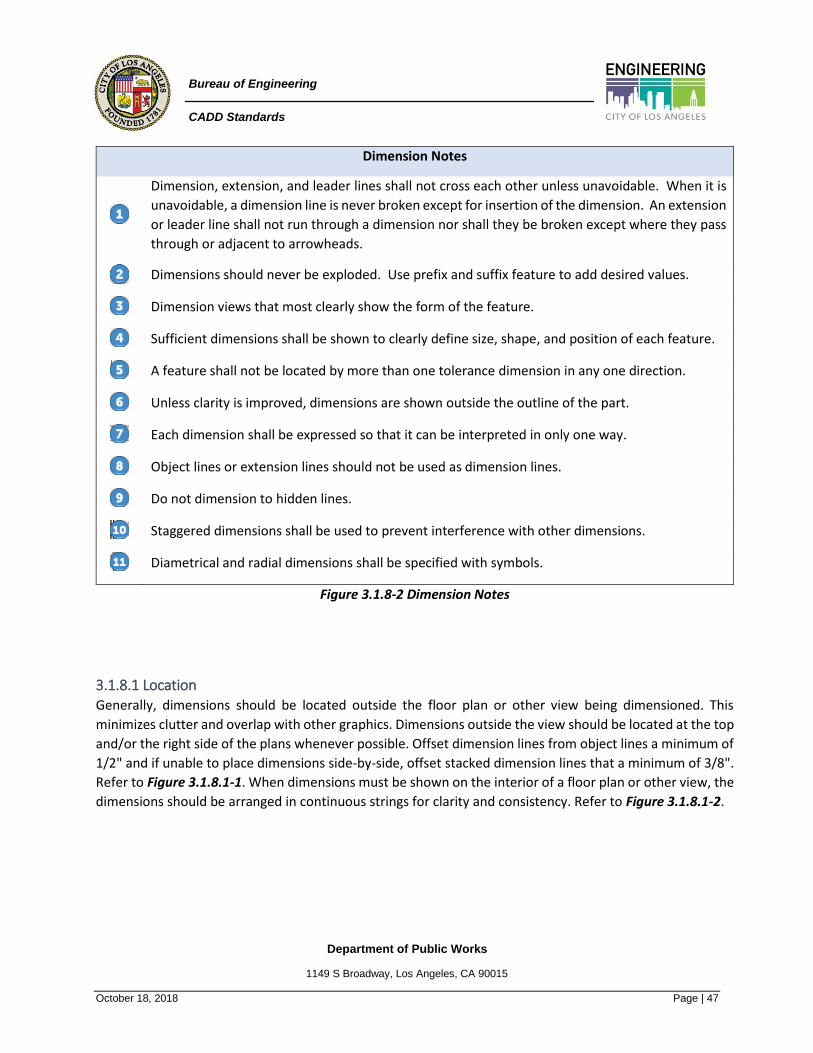
Department of Public Works
1149 S Broadway, Los Angeles, CA 90015
October 18, 2018 Page | 47
Bureau of Engineering
CADD Standards
Dimension Notes
Dimension, extension, and leader lines shall not cross each other unless unavoidable. When it is
unavoidable, a dimension line is never broken except for insertion of the dimension. An extension
or leader line shall not run through a dimension nor shall they be broken except where they pass
through or adjacent to arrowheads.
Dimensions should never be exploded. Use prefix and suffix feature to add desired values.
Dimension views that most clearly show the form of the feature.
Sufficient dimensions shall be shown to clearly define size, shape, and position of each feature.
A feature shall not be located by more than one tolerance dimension in any one direction.
Unless clarity is improved, dimensions are shown outside the outline of the part.
Each dimension shall be expressed so that it can be interpreted in only one way.
Object lines or extension lines should not be used as dimension lines.
Do not dimension to hidden lines.
Staggered dimensions shall be used to prevent interference with other dimensions.
Diametrical and radial dimensions shall be specified with symbols.
Figure 3.1.8-2 Dimension Notes
3.1.8.1 Location Generally, dimensions should be located outside the floor plan or other view being dimensioned. This
minimizes clutter and overlap with other graphics. Dimensions outside the view should be located at the top
and/or the right side of the plans whenever possible. Offset dimension lines from object lines a minimum of
1/2" and if unable to place dimensions side-by-side, offset stacked dimension lines that a minimum of 3/8".
Refer to Figure 3.1.8.1-1. When dimensions must be shown on the interior of a floor plan or other view, the
dimensions should be arranged in continuous strings for clarity and consistency. Refer to Figure 3.1.8.1-2.

Department of Public Works
1149 S Broadway, Los Angeles, CA 90015
October 18, 2018 Page | 48
Bureau of Engineering
CADD Standards
Figure 3.1.8.1-1 Dimensioned floor plan, exterior
dimensions
Figure 3.1.8.1-2 Dimensioned floor plan,
interior dimensions
3.1.8.2 Types of Terminators Terminators define the junction between a dimension line and the extension lines leading to the start and
finish of the dimension. These terminators are in the form of either a short, slanted line (slash) typically used
for building projects or a filled arrowhead that are typically used for infrastructure projects. Refer
to Figure 3.1.8.2-1. Slashes should always be parallel. Dimension terminator selection should be consistent
across the entire set of drawings.
Figure 3.1.8.2-1 Dimensioned floor plan, exterior dimensions

Department of Public Works
1149 S Broadway, Los Angeles, CA 90015
October 18, 2018 Page | 49
Bureau of Engineering
CADD Standards
3.1.8.3 Numerical Size and Location Numeral size should match the specified drawing text height of 1/8” and the Arial text style font. Where
possible, the numeral should be placed at the midpoint and on top of the dimension line using the offset
0.06 units as specified in the BOE Dimension Style. Refer to Figure 3.1.8.3-1. The terminator should be 1/8”.
Figure 3.1.8.3-1 Numerical Size and Location
3.1.8.4 Plan Dimensions What to dimension from and to depends on the structural system and the sequence and stage of
construction of a given building type or street width and utility locations for an infrastructure site plan. Steel
frame and reinforced concrete buildings are normally dimensioned from column centerline to column
centerline. This should include an additional dimension to the face of the finished building. Street widths on
infrastructure plans are normally dimensioned indicating street width and right-of-way widths along the
roadway. Refer to Figure 3.1.8.4-1. For concrete framed multistory buildings, perimeter columns may be
dimensioned to the face of the column rather than the centerline if the column depth is reduced in upper
floors while the building facade remains constant. Refer to Figure 3.1.8.4-2.
Figure 3.1.8.4-1 Site Plan Dimensioning.

Department of Public Works
1149 S Broadway, Los Angeles, CA 90015
October 18, 2018 Page | 50
Bureau of Engineering
CADD Standards
Figure 3.1.8.4-2 Structural systems dimensioning
3.1.8.5 Vertical Dimensions Vertical dimensions follow a hierarchy similar to the one described under plans progressing from detailed
dimensions close to the wall to overall dimensions farthest from it. Eliminate excessive repetition of
dimensions from small scale to large scale.
Before the layout of building plans can proceed on site, a start point for vertical dimensioning must be
located. In some areas, coast and geodetic datum relative to mean sea level are available and should be
shown on the plans and sections. In other areas referencing benchmarks or street curb datum as available is
convenient. Refer to Figure 3.1.8.5-1.
Figure 3.1.8.5-1 Layout of building plan

Department of Public Works
1149 S Broadway, Los Angeles, CA 90015
October 18, 2018 Page | 51
Bureau of Engineering
CADD Standards
3.1.9 Notations The Notations Module includes standards for different types of notes on different types of drawings. The
purpose of notations associated with construction drawings is to perform the following functions:
• Provide information relevant to the entire set of documents, or individual disciplines, or individual
sheets.
• Identify products, materials, components, or assemblies using the same terminology used in the
specifications.
• Inform drawing users as to the design’s execution requirements.
Brevity should be a guideline for writing notations. The following are other guidelines for notations:
• Select notes to identify, but not overly describe, the materials, components, and assemblies.
• Use generic terms for products, materials, and components. Refer to MasterFormat™.
• Minimize use of abbreviations. Refer to the Terms and Abbreviations Module.
• Use consistent terminology between drawings and specifications.
• Compose notations without defining a specific contractor to do the work unless laws require the
division of work according to a filed sub-bid. An exception may be multiple prime contracts that may
require a defined division of the work.
• Avoid being specific about the sequence of construction. Unless required for public convenience,
safety, or operations.
• Eliminate repetition of notations on a sheet.
• Eliminate broad references to the specifications such as notes that state "per specs" or "refer to
contract."
3.1.9.1 Tables, Schedules and Diagrams Notes used in tables, schedules, and diagrams should be brief. Refer to Figure 3.1.9.1-1. Single terms using
the approved abbreviations, verified with the GI sheets, provide a simple, clear, and efficient means of
communication.

Department of Public Works
1149 S Broadway, Los Angeles, CA 90015
October 18, 2018 Page | 52
Bureau of Engineering
CADD Standards
Figure 3.1.9.1-1 Notes for tables, schedules, and diagrams.
3.1.9.2 Identifying Spaces and Objects Spaces and objects in a building are identified to easily locate and to simplify the preparation of schedules.
The identifier is used in drawings, schedules, and specifications to fully describe the space or object in
question.
3.1.9.3 Graphic Conventions for Text The minimum text size is 1/8" for CAD. Smaller text size is generally not legible on reduced or one-half size
sets. All text placed in a drawing is to be upper case, and except for street names, should not include slant,
oblique, or bold text. Refer to Figures 3.1.9.3-1 and 3.1.9.3-2. When possible, most text should be horizontal
as shown in Figure 3.1.9.3-3. The use of bold, italic, and underline should not be used for notes.
Text
Size Use
0.25 (1/4)” Primary Text (Sheet Headings
0.188 (3/16”) Secondary Text (View Identifications, Note & Schedule Headings)
0.16 (5/32”) Tertiary Text (Match Line Titles, Street Names, Building Names)
0.125 (1/8”) General Text (Notes, Dimensions, Rome Names, Labels, Schedules,
Misc)
0.09 (3/32”) Compact Text (File path, Disclaimers, Footnotes, Title Block)
Notes: All Text is upper case
All text is Arial font
No slant, oblique or bold text except Street Names
Text horizontal with few exceptions (e.g. street names)
Figure 3.1.9.3-1 Graphic Conversions for Text
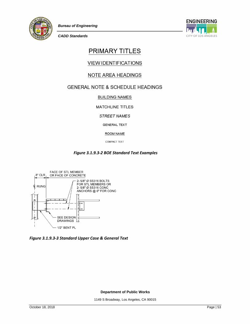
Department of Public Works
1149 S Broadway, Los Angeles, CA 90015
October 18, 2018 Page | 53
Bureau of Engineering
CADD Standards
Figure 3.1.9.3-2 BOE Standard Text Examples
Figure 3.1.9.3-3 Standard Upper Case & General Text
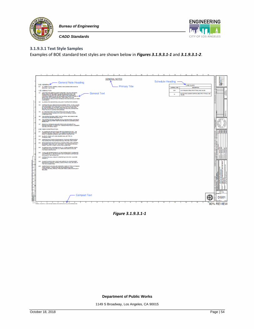
Department of Public Works
1149 S Broadway, Los Angeles, CA 90015
October 18, 2018 Page | 54
Bureau of Engineering
CADD Standards
3.1.9.3.1 Text Style Samples
Examples of BOE standard text styles are shown below in Figures 3.1.9.3.1-1 and 3.1.9.3.1-2.
Figure 3.1.9.3.1-1

Department of Public Works
1149 S Broadway, Los Angeles, CA 90015
October 18, 2018 Page | 55
Bureau of Engineering
CADD Standards
Figure 3.1.9.3.1-2
3.1.10 Cross References Cross-referencing provides a system for tracking information from the general to the specific within a
drawing set. The master drawing for a cross-referencing system is the floor plan. The floor plan should
contain references to the building sections, elevations, interior elevations, plan details, and other
information necessary to fully describe the project. A properly cross-referenced drawing set does not
duplicate information but provides it one time in the expected location.
A poorly referenced project is subject to misinterpretation by contractors, owners, architects, engineers, and
building officials. It can increase the cost of the drawings and construction due to required addenda,
clarifications, and possibly change orders.
Proper cross-referencing does not require any extra effort. The most efficient way to do this while
maintaining control over the process is to create a comprehensive and detailed mock-up of the project. Refer
to section 3.3 Mock-up Drawing Set.
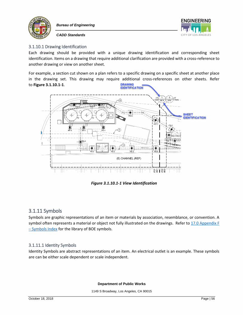
Department of Public Works
1149 S Broadway, Los Angeles, CA 90015
October 18, 2018 Page | 56
Bureau of Engineering
CADD Standards
3.1.10.1 Drawing Identification Each drawing should be provided with a unique drawing identification and corresponding sheet
identification. Items on a drawing that require additional clarification are provided with a cross-reference to
another drawing or view on another sheet.
For example, a section cut shown on a plan refers to a specific drawing on a specific sheet at another place
in the drawing set. This drawing may require additional cross-references on other sheets. Refer
to Figure 3.1.10.1-1.
Figure 3.1.10.1-1 View Identification
3.1.11 Symbols Symbols are graphic representations of an item or materials by association, resemblance, or convention. A
symbol often represents a material or object not fully illustrated on the drawings. Refer to 17.0 Appendix F
– Symbols Index for the library of BOE symbols.
3.1.11.1 Identity Symbols Identity Symbols are abstract representations of an item. An electrical outlet is an example. These symbols
are can be either scale dependent or scale independent.

Department of Public Works
1149 S Broadway, Los Angeles, CA 90015
October 18, 2018 Page | 57
Bureau of Engineering
CADD Standards
3.1.11.2 General Symbols General Symbols indicate drawing orientation, scale, defined project area, and design feature status. These
symbols are drawn to scale. Refer to Figure 3.1.11.2-1.
Figure 3.1.11.2-1 General Symbols
3.1.11.3 Line Symbols Line Symbols indicate continuous objects and are either single or double lines. Walls are usually drawn with
two lines and ducts with one or two lines based on the scale of the drawing. Refer to Figure 3.1.12.3-1.
Figure 3.1.11.3-1 Line Symbols
Department of Public Works
1149 S Broadway, Los Angeles, CA 90015
October 18, 2018 Page | 58
Bureau of Engineering
CADD Standards
3.1.11.4 Material Symbols Some material symbols are used in drawings to help the viewer understand the use and extent of materials.
They are used to portray a material graphically in plan, elevation, or section and are drawn to scale. A graphic
representation of concrete is an example. Refer to section 4.0 Symbols. Symbols should provide
identification of material. Detailed information about the indicated graphic material should be placed in the
specifications.
Material symbols may define general use if the material covers the entire surface, or a specific pattern such
as the coursing and placement of bricks. For clarity, notes calling out the material may be used in lieu or
addition to the graphic symbol.
3.1.11.4.1 Hatching
Hatching refers to the patterns of repetitive lines, dots, or figures used to indicate specific types of materials
or designate specific areas. Hatching is very useful in making drawings readable. Use it only to indicate
specific materials such concrete, asphalt, or specific areas where work is to be done. For example, drawings
shown at 1:100 (1/8" = 1'-0") or smaller rarely require any hatching to indicate materials. Use a hatch pattern
to indicate a specific area of flooring to be removed within a larger area of flooring to remain.
Select small areas to be hatched that will clearly identify the entire area. Indicate hatching where materials
change or terminate. Hatching should be used as extensively as necessary to promote clarity in the drawing.
3.1.11.4.2 Scale in Material Indications
Small-scale plans and sections should use simplified versions of the material indication symbol to keep from
cluttering the drawing. Large-scale details should use material indication symbols that have enough detail to
describe clearly the material and its size.
Note: The BOE uses annotative hatches to automatically adjust scales per views.
3.1.11.5 Object Symbols Object Symbols represent items such as furniture and toilet fixtures. These symbols are drawn to scale.
3.1.11.6 Reference Symbols Reference Symbols refer the reader to another part of the documentation. Partition type symbol, section
cuts, and elevation references are examples.
3.1.11.7 Text Symbols Text Symbols graphically indicate a word or words and may be used in notations on drawings. For letter
symbols, dimensionless numbers, mathematical symbols, and subscript symbols, refer to ASHRAE Handbook
- Fundamentals.
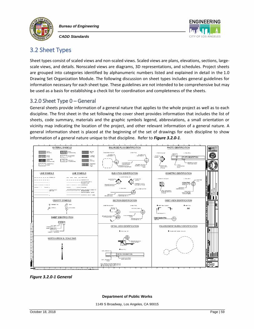
Department of Public Works
1149 S Broadway, Los Angeles, CA 90015
October 18, 2018 Page | 59
Bureau of Engineering
CADD Standards
3.2 Sheet Types
Sheet types consist of scaled views and non-scaled views. Scaled views are plans, elevations, sections, large-
scale views, and details. Nonscaled views are diagrams, 3D representations, and schedules. Project sheets
are grouped into categories identified by alphanumeric numbers listed and explained in detail in the 1.0
Drawing Set Organization Module. The following discussion on sheet types includes general guidelines for
information necessary for each sheet type. These guidelines are not intended to be comprehensive but may
be used as a basis for establishing a check list for coordination and completeness of the sheets.
3.2.0 Sheet Type 0 – General General sheets provide information of a general nature that applies to the whole project as well as to each
discipline. The first sheet in the set following the cover sheet provides information that includes the list of
sheets, code summary, materials and the graphic symbols legend, abbreviations, a small orientation or
vicinity map indicating the location of the project, and other relevant information of a general nature. A
general information sheet is placed at the beginning of the set of drawings for each discipline to show
information of a general nature unique to that discipline. Refer to Figure 3.2.0-1.
Figure 3.2.0-1 General

Department of Public Works
1149 S Broadway, Los Angeles, CA 90015
October 18, 2018 Page | 60
Bureau of Engineering
CADD Standards
3.2.1 Sheet Type 1 - Plans Typical components of plans, shown in Figure 3.2.1-1, include the following information:
• Drawing Scales: Indicate scale on plans. Refer to section 3.1.5.1 Scales for information on scales.
• Column Grid Lines: If used (may be omitted on Civil and Landscape plans).
• True North Arrow and Plan North Arrow: If used.
• Key Plans: Show clearly the relationship among the elements of complex projects or where the size
of one element requires two or more drawings to delineate a level. Include column grids adjacent to
match lines and corners; do not label rooms or departments.
Figure 3.2.1-2 Plan
Figure 3.2.1-1 Plan Views

Department of Public Works
1149 S Broadway, Los Angeles, CA 90015
October 18, 2018 Page | 61
Bureau of Engineering
CADD Standards
3.2.1.1 Civil Plans Civil plans include site demolition, site improvement, dimension control, grading, paving, and site utilities
plans. Dimension control plans show benchmarks and survey control point locations as well as
interrelationships among buildings, streets, parking areas, fences, and utilities. Grading plans define limits
of all grading work, provide critical spot elevations, and set controlling grades to ensure proper site drainage.
Paving plans establish base lines for large paved areas, locate roads, and indicate types of paving. Site utilities
plans show the size and location of all new and existing utilities.
Include the north arrow, key plan, match lines (if used), scale, and column grid described at the start of Type
1 Sheets. The following list of items should be included in all Civil plans:
3.2.1.1.1 Site Demolition Plans
Typical components of demolition plans include the following information:
• Limits of items to be removed from the site including planting, exterior lighting, and paved areas.
• Curbs to be cut as well as trees and plantings to be protected.
• Locations of existing structures and utilities to remain.
• Items to be demolished and removed from site.
• Items to be salvaged and turned over to owner.
• Items to remain undisturbed and be protected.
3.2.1.1.2 Dimension Control or Layout Plans
Typical components of dimension control or layout plans include the following information:
• Base plans showing information from field survey including benchmark and survey control point
locations.
• Interrelationships of buildings, streets, parking areas, fences, and utilities.
• Locations for access and egress to facilities.
• Horizontal layout for fencing.
• Location and limits of site improvements.
Guidelines for Dimension Control or Layout Plans
• Structures should be located by horizontal coordinates where possible. Reinforced concrete
structures should be located relative to face or centerline of wall. Steel structures should be located
by grid line.
• Do not show dimensions or elevations of structures already shown on Architectural or Structural
drawings. Adequate dimensions should be provided so that nothing has to be scaled from the
drawings. Include inverts for graded (sloped) site utility lines at point of connection to building
utilities.
Department of Public Works
1149 S Broadway, Los Angeles, CA 90015
October 18, 2018 Page | 62
Bureau of Engineering
CADD Standards
3.2.1.1.3 Grading Plans
Typical components of grading plans include the following information:
• Site grading with controlling grades to ensure proper drainage. Critical spot elevations must be
positioned relative to a survey control point, structure, or road baseline.
• Limits of grading work.
• Sizes of new drainage facilities with controlling grades.
• Modified contours for the new design. Relate them to the building outline to ensure positive
drainage to catch basins and other discharge points.
• Spot elevations at corners and points adjacent to building entrances.
3.2.1.1.4 Paving Plans
Typical components of paving plans include the following information:
• Large paved areas. Locate by establishing a baseline.
• Roads. Locate based on a centerline horizontal alignment.
• Paving. Indicate types.
• Core lines and expansion, contraction, and control joints. Dimension each item to the nearest fixed
point.
3.2.1.1.5 Site Utilities Plans
Typical components of site utilities plans include the following information:
• New or existing utilities to service new facilities. Show sizes, inverts, and location of connection to
existing lines.
• Existing site utility structures. Adjust to meet new grading requirements.
• Site utilities. Show extent to within 1.5 m (5'-0") from building. Reference Mechanical and Electrical
site utilities plans, if used.
Guidelines for Site Utilities Plans
• Ensure that the interface between site and building utilities are at the same location.
• Check ground-floor elevation against spot elevations adjacent to entrances.
• Check the location of curb cuts against new driveways.
• Check elevation of ledges supporting masonry shown on the elevations against grade elevations
shown on Civil or Landscape plan.
Department of Public Works
1149 S Broadway, Los Angeles, CA 90015
October 18, 2018 Page | 63
Bureau of Engineering
CADD Standards
3.2.1.2 Landscape Plans These plans may include site preparation (indicating structures to be demolished and plants to be removed),
irrigation, and plant materials plans. Site preparation plans show existing site features to be modified,
including planting to be removed, curbs to be cut, exterior lighting, paving areas to be removed, and trees
to be protected. Irrigation plans dimension layout of the irrigation piping and sprinkler heads and the
locations of controllers as well as their power supply. Plant material plans show dimension layout of
landscape material, and designate plant types and their quantity.
In addition to the items listed at the start of Type 1 Sheet, the following list of items should be included on
all Landscape plans:
3.2.1.2.1 Site Preparation Plans
Typical components of site preparation plans include the following information:
• Outline (at grade) and names of buildings and/or structures.
• Walks, streets, curbs, parking areas, signs, planters, light poles, and other site structures.
3.2.1.2.2 Irrigation Plans
Typical components of irrigation plans include the following information:
• Layout of irrigation items. Dimension to the nearest fixed point.
• Coordinate location of irrigation controllers with architectural, mechanical, and power requirements
with Electrical plans.
3.2.1.2.3 Plant Materials Plans
Typical components of plant material plans include the following information:
• Names of buildings and/or structures. Show outline (at grade).
• Walks, streets, curbs, parking areas, signs, planters, light poles, and other site structures.
• Layout of landscape materials. Dimension to nearest fixed point.
• Show designations, location, spacing, and quantity of materials for planting.
• Schedule of plant materials for each planting plan.
3.2.1.3 Structural Plans Structural plans include demolition, foundation, and framing plans. These plans define support and bracing
elements (columns and shear walls) of the building. Horizontal support members such as beams, girders,
and trusses must be coordinated with other discipline elements passing through or beneath them to
eliminate conflict among these disciplines.

Department of Public Works
1149 S Broadway, Los Angeles, CA 90015
October 18, 2018 Page | 64
Bureau of Engineering
CADD Standards
In addition to the items listed at the start of Type 1 Sheets, the following list of items should be included in
Structural plans:
3.2.1.3.1 Foundation Plans and Slab-on-Grade Framing Plans
Typical components of foundation and slab-on-grade framing plans include the following information:
• Column piers and footings.
• Footings. Indicate top of footing elevations on all spread footings. Also show top of pier elevations.
• Grade beams or walls required under masonry walls.
• Expansion, control, and seismic joints. Label, dimension, and detail each. Indicate thickened edges
that will occur on each side of the joint for slabs on grade.
• Top of slab elevation on all plans.
• Slab block-outs. Dimension vertically and horizontally. Dimension boundaries of areas with different
slab thickness and/or reinforcing requirements.
• Footings for stairways and shear walls. Dimension in plan and indicate top of footing elevation.
• Stairs and ramps. Dimension in plan and assign a number to each stair. Only overall plan dimensions
should be shown. Treads and risers will be dimensioned on large-scale plans and sections.
• Dowels to masonry walls. Identify and show location.
• Floor slopes to drains and spot elevations. Show relative floor elevations.
• Pits, trenches, floor recesses, and tunnels. Show, locate, dimension, and detail each.
• Curbs. Show notes, dimensions, and details.
• Concrete equipment pads.
• Bonding or grounding of structural and/or reinforcing steel for lightning protection.
• Water stops, where required.
• Membrane waterproofing or vapor retarder under soil bearing slabs, pits, and trenches.
Guidelines for Foundation Plans and Slab-on-Grade Framing Plans
• Dimension plans fully for all offsets and provide overall dimensions as required. Dimension to edges
of slabs where they occur. Coordinate with Architectural plans and dimensions.
• Footings need not be dimensioned if they are symmetrical about the column grid; otherwise, plan
dimensions will be required to show location with respect to column grid. Coordinate with
Architectural plans.
• Footings that step-in elevation are indicated and dimensioned.
3.2.1.3.2 Floor and Roof Framing Plans
Typical components of floor and roof framing plans include the following information:
• Girders, miscellaneous cast-in-place concrete beams, steel beams, slabs, and channels. Locate
dimensionally.
Department of Public Works
1149 S Broadway, Los Angeles, CA 90015
October 18, 2018 Page | 65
Bureau of Engineering
CADD Standards
• Edges of slabs. Dimension to nearest gridline or reference point.
• Label all slab block-outs as "open" and dimension, both vertically and horizontally. Indicate method
of additional reinforcement around the opening.
• Top of slab elevation on all plans.
• Brackets. Assign a mark number to each but do not dimension.
• Expansion, control, and seismic joints. Label, dimension, and detail each.
• Stairs and ramps. Dimension fully in plan. Stairs should be indicated by stair number. Only overall
plan dimensions should be required. Treads and risers will be dimensioned on sections.
• Bracing elements such as shear walls and braced walls. Indicate location and identify.
• Concrete handrails. Indicate location and dimension.
• Dowels to masonry walls, if required. Indicate location and identify.
• All masonry and lintel locations on the plans and in a lintel schedule.
Guidelines for Floor and Roof Framing Plans
• Assign a member identification mark to all framing members.
• Dimension centerlines of all beams. Dimension to edge of spandrels or beams at openings.
• Show spacing of all joists on framing plans and locate all bridging.
• Show floor and roof slopes to drains and spot elevations. Show relative floor and roof elevations.
• Refer to the structural floor plan above the floor being considered when checking for overhead
clearances.
• Do not indicate the size of structural members on Architectural drawings.
• Dimension slab openings for skylights, roof hatches, major duct penetrations, depressed slabs, and
concrete curbs.
3.2.1.4 Architectural Plans Architectural plans include demolition, floor, reflected ceiling, and roof plans.
3.2.1.4.1 Floor Plans
All architectural drawings are generated from the plans. Plans provide information about dimensions,
partition types, room, and door numbers as well as references to elevations, building sections, wall sections,
enlarged plans, details, window types, and schedules. Exterior window types may be shown on the plans or
elevations but not on both.
3.2.1.4.2 Floor Numbering
Number ground floor as F1. The F1 floor is defined by the Architect, in consultation with the Owner and
building department. It is usually the main entry floor or the floor on which the Fire Alarm Control Panel is
located. Note that the applicable building code also may stipulate how to define floor F1. Refer to
Figure 3.2.1.4.2-1 Examples of Floor Numbering.
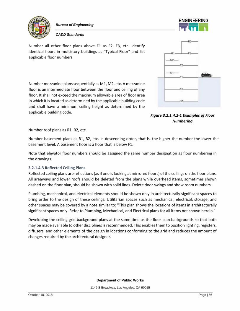
Department of Public Works
1149 S Broadway, Los Angeles, CA 90015
October 18, 2018 Page | 66
Bureau of Engineering
CADD Standards
Number all other floor plans above F1 as F2, F3, etc. Identify
identical floors in multistory buildings as "Typical Floor" and list
applicable floor numbers.
Number mezzanine plans sequentially as M1, M2, etc. A mezzanine
floor is an intermediate floor between the floor and ceiling of any
floor. It shall not exceed the maximum allowable area of floor area
in which it is located as determined by the applicable building code
and shall have a minimum ceiling height as determined by the
applicable building code.
Figure 3.2.1.4.2-1 Examples of Floor
Numbering
Number roof plans as R1, R2, etc.
Number basement plans as B1, B2, etc. in descending order, that is, the higher the number the lower the
basement level. A basement floor is a floor that is below F1.
Note that elevator floor numbers should be assigned the same number designation as floor numbering in
the drawings.
3.2.1.4.3 Reflected Ceiling Plans
Reflected ceiling plans are reflections (as if one is looking at mirrored floors) of the ceilings on the floor plans.
All areaways and lower roofs should be deleted from the plans while overhead items, sometimes shown
dashed on the floor plan, should be shown with solid lines. Delete door swings and show room numbers.
Plumbing, mechanical, and electrical elements should be shown only in architecturally significant spaces to
bring order to the design of these ceilings. Utilitarian spaces such as mechanical, electrical, storage, and
other spaces may be covered by a note similar to: "This plan shows the locations of items in architecturally
significant spaces only. Refer to Plumbing, Mechanical, and Electrical plans for all items not shown herein."
Developing the ceiling grid background plans at the same time as the floor plan backgrounds so that both
may be made available to other disciplines is recommended. This enables them to position lighting, registers,
diffusers, and other elements of the design in locations conforming to the grid and reduces the amount of
changes required by the architectural designer.

Department of Public Works
1149 S Broadway, Los Angeles, CA 90015
October 18, 2018 Page | 67
Bureau of Engineering
CADD Standards
3.2.1.4.4 Roof Plans
Roof plans should be grouped with the floor plans and drawn at the same scale. Do not show site or building
information located below the roofline.
In addition to the information shared by all plan sheets that are listed at the start of Type 1 Sheets, the
following list of items should be included on all Architectural floor plans:
Floor Plans
• Room names and numbers.
• Doors and door numbers.
• Windows and window type numbers, if these are not shown on elevations.
• Floor plan dimensions. Locate walls and partitions, level changes, and close strings of dimensions
from column grid to column grid. Refer to section 3.1.7.5 Dimension Lines.
• Partition types. Refer to Sheet Type 6 - Schedules and Diagrams below.
• Borrowed light and louver types.
• Exterior and interior wall elevation references.
• Building section references.
• Wall section references.
• Floor plan horizontal detail references.
• Termination of floor materials within a room.
• Floor drain and slope lines of drainage to floor drain. Show extent and direction of slope.
• Plumbing fixtures.
• Fire hose, and hose cabinets.
• Fire extinguishers and extinguisher cabinets.
• Built-in casework, shelving, lockers, benches, kitchen casework, and equipment. See Classifications
of Furniture, Fixtures, and Equipment definition in Interior plans below.
• Openings in the floor such as elevator and dumbwaiter shafts, mechanical/ plumbing/electrical
shafts, atria, stairs, and escalators. Do not show an "X" through a chase unless entire chase is a floor
penetration.
• Trenches and other recessed areas needing depressions in the floor, such as recessed floor mats,
thickset ceramic tile, and other items. Dimension and detail each.
• References to details and sheet notes.
• Significant overhead features such as balconies, skylights, beams, and roof overhangs. Indicate with
a dashed line and add a note describing what that line represents.
• Edge of slabs, ledges, equipment pads, and curbs. Do not show walls and bridges at the next level
below, or items that appear on another floor or roof plan. Make sure that the structural drawing set
contains the details required to illustrate these items.
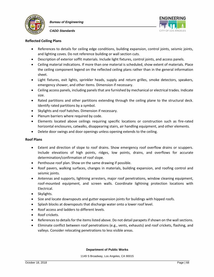
Department of Public Works
1149 S Broadway, Los Angeles, CA 90015
October 18, 2018 Page | 68
Bureau of Engineering
CADD Standards
Reflected Ceiling Plans
• References to details for ceiling edge conditions, building expansion, control joints, seismic joints,
and lighting coves. Do not reference building or wall section cuts.
• Description of exterior soffit materials. Include light fixtures, control joints, and access panels.
• Ceiling material indications. If more than one material is scheduled, show extent of materials. Place
the ceiling component legend on the reflected ceiling plans rather than in the general information
sheet.
• Light fixtures, exit lights, sprinkler heads, supply and return grilles, smoke detectors, speakers,
emergency shower, and other items. Dimension if necessary.
• Ceiling access panels, including panels that are furnished by mechanical or electrical trades. Indicate
size.
• Rated partitions and other partitions extending through the ceiling plane to the structural deck.
Identify rated partitions by a symbol.
• Skylights and roof hatches. Dimension if necessary.
• Plenum barriers where required by code.
• Elements located above ceilings requiring specific locations or construction such as fire-rated
horizontal enclosures, catwalks, disappearing stairs, air handling equipment, and other elements.
• Delete door swings and door openings unless opening extends to the ceiling.
Roof Plans
• Extent and direction of slope to roof drains. Show emergency roof overflow drains or scuppers.
Include elevations of high points, ridges, low points, drains, and overflows for accurate
determination/confirmation of roof slope.
• Penthouse roof plan. Show on the same drawing if possible.
• Roof pavers, walking surfaces, changes in materials, building expansion, and roofing control and
seismic joints.
• Antennas and supports, lightning arresters, major roof penetrations, window cleaning equipment,
roof-mounted equipment, and screen walls. Coordinate lightning protection locations with
Electrical.
• Skylights.
• Size and locate downspouts and gutter expansion joints for buildings with hipped roofs.
• Splash blocks at downspouts that discharge water onto a lower roof level.
• Roof access and ladders to different levels.
• Roof crickets.
• References to details for the items listed above. Do not detail parapets if shown on the wall sections.
• Eliminate conflict between roof penetrations (e.g., vents, exhausts) and roof crickets, flashing, and
valleys. Consider relocating penetrations to less visible areas.
Department of Public Works
1149 S Broadway, Los Angeles, CA 90015
October 18, 2018 Page | 69
Bureau of Engineering
CADD Standards
3.2.1.5 Interior Plans Interior plans include demolition, furniture, furnishings, fixtures, and equipment plans. These plans are
usually drawn on the architectural backgrounds without the symbols or dimensions layers. These plans are
used by the electrical engineer to locate outlets, power requirements, and lighting.
In addition to the information listed at the beginning of Type 1 Sheets, and usually provided on the screened
Architectural background plans, the following list of items should be included on all Interior floor plans:
• Borrowed light and louver openings.
• Interior room elevation references.
• Pertinent tables, schedules, key, and sheet notes.
• Building expansion and seismic joints if they intersect and affect furniture and equipment
installations.
• Trenches and other recessed areas with depressions.
• Fire-hose cabinets that contain fire extinguishers, extinguisher cabinets, and wall-mounted
extinguishers. Coordinate locations with Architectural and Fire Protection plans.
• Drinking fountains, water coolers, and all other plumbing fixtures.
• Toilet partitions, toilet casework, and toilet accessories.
Guidelines for Interior Plans
• Indicate rooms with equipment or custom furniture or other areas to be enlarged by a dashed line
around the area. Reference to enlarged plan. Show furniture and equipment on enlarged plan only.
Do not duplicate information shown on smaller scale plans. Show interior elevation references on
the enlarged plan.
• Coordinate location of furniture and equipment with lockers, cabinets, chalkboards, tackboards,
electrical outlets, thermostats, clock outlets, and other items contained in the
Architectural/Engineering documents.
• Identify each item of furniture and equipment by a mark number.
Classifications of Furniture, Fixtures, and Equipment
Class 1: Permanently fixed items with permanent utility connections, such as stoves, dishwashers, steam
tables, light fixtures, wall switches, water chillers, air handling units, bridge cranes, pumps, electrical
generators, transformers, and switch gear; and large fixed shop equipment such as automatic cutting
machines, air compressors, jib cranes, large cleaning and plating tanks, and milling machines.
Class 2: Portable items with flexible or quick-disconnect utility connections, including office and household
items such as computers, calculators, electric coffee pots, vacuum cleaners, table lamps, floor lamps,
window air conditioning units, household refrigerators, and television sets; and shop equipment such as

Department of Public Works
1149 S Broadway, Los Angeles, CA 90015
October 18, 2018 Page | 70
Bureau of Engineering
CADD Standards
powered hand drills (electric and pneumatic), powered hand-held saws, air compressors, welding machines,
oxyacetylene cutting and welding outfits, and paint sprayers.
Class 3: Movable items without utility connections, including office and household furnishings such as chairs,
sofas, stands, desks, tables, rugs, beds, and shop equipment such as tool cabinets, work benches, storage
racks, storage bins, storage shelves, bench-mounted vises, hand-powered trucks for handling compressed
gas tanks, and A-frame cranes.
Class 4: Expendable and consumable items, including expendables such as window curtains, shower curtains,
bed linens, uniforms, clothing, brooms, wall mirrors, wall pictures, tableware, crystal ware, kitchen cutlery,
cooking utensils, hand tools (pliers, screwdrivers, wrenches), mechanics' tool kits, test equipment (small
battery-powered, hand-held voltmeters and multi-meters), and storage aids (plastic storage bins and shelf
separators); and consumables such as products with limited shelf life (medicines, chemicals, paints, and
food), household supplies (soaps, cleansers, and ammonia solutions), office supplies, shop supplies (nuts,
bolts, welding rods, fluxes, electrical tape), janitorial supplies (wiping cloths, paper towels, toilet paper, and
oil-absorbent sweeping materials).
3.2.1.6 Fire Protection and Plumbing Plans These plans include floor and demolition plans. They define the piping required to connect fixtures, floor and
roof drains, fire pumps, fire hose cabinets, sprinkler heads, and other elements of the plumbing system. For
some industrial projects, such as lab and medical facilities, plans include gas, air, vacuum, and special waste
piping.
3.2.1.6.1 Plumbing Plans
• Ensure that furring for pipes located in proximity to columns does not conflict with beams and
column base plates.
• Size partitions and pipe chases to accommodate the pipes they enclose.
• Group vent pipes at a limited number of locations to minimize penetrations. Design pipes crossing
from one side of an expansion joint to the other to accommodate the movement between the two
sides.
3.2.1.7 Mechanical Plans Mechanical plans showing demolition of existing components of the mechanical system or the duct, pipe,
and heating media layout for new construction are overlaid on the architectural background. For better
readability of mechanical plans, screen the architectural background to a lighter shade. Mechanical plans
must identify same unit designations that appear in schedules, indicate all sections, reference all details, and
size louvers and openings.

Department of Public Works
1149 S Broadway, Los Angeles, CA 90015
October 18, 2018 Page | 71
Bureau of Engineering
CADD Standards
In addition to the items listed at the beginning of Type 1 Sheets, and usually shown on the backgrounds, the
following list of items should be included in all Mechanical plans:
• Exterior and interior louver openings.
• Piping sized in U.S. standard.
• Ductwork sized with clear inside dimensions. Air quantities should be indicated in L/s (CFM).
• Mechanical rooms and other areas to be enlarged. Indicate by a dashed line around the area.
Reference to the enlarged plan. Do not duplicate information.
• Turning vanes, splitters, and extractors.
• Fire dampers and control dampers. Coordinate locations with Architectural and Electrical plans.
• Duct connections to kitchen hoods, lab hoods, and other equipment requiring supply or exhaust air.
• Duct-mounted coils.
• Pipe sleeves.
• Thermostat locations and reference unit or zone controls. Coordinate locations with architectural
and Interiors.
• Sound attenuators.
• Valves.
• Vibration isolation elements.
3.2.1.7.1 Mechanical Room Plans
Confine area of enlargement to that portion referenced on smaller scale plans. Reference all applicable
details and diagrams. Make and indicate sufficient section cuts to adequately convey layout to the
contractor. Indicate future equipment with dashed lines and note as future. Express all air quantities in L/s
(CFM). Also, show the following:
• Equipment by unit designations as contained on the schedules.
• Ductwork with double lines.
• Piping 50 mm (2") and larger with double lines. Piping smaller than 50 mm (2") should be indicated
with single lines.
• Other equipment located in mechanical room should be shown with light dashed lines.
• Air handling units complete with motor locations, filter sections, flexible connections, and mixing
box sections.
• Air handling unit drain connection and routing to floor drain.
• Equipment pads or applicable support method; coordinate with Architectural and Structural plans.
• Dampers.
• Sound traps and internally lined ductwork.
• Valves.
• Roof plan.
• Roof-mounted equipment and indicate the maximum allowable height for each.

Department of Public Works
1149 S Broadway, Los Angeles, CA 90015
October 18, 2018 Page | 72
Bureau of Engineering
CADD Standards
Guidelines for Mechanical Room Plans
• Coordinate locations of all plenum barriers with Architectural plans.
• Coordinate location of motorized dampers with Electrical plans.
• Coordinate location and size of door undercuts and grilles with Architectural plans. Eliminate
undercuts or grilles if the door is located in a fire-rated partition.
• Coordinate location and size of outside and combustion air intakes with Architectural plans.
• Coordinate size and location of screen walls and related ventilation requirements for condensing
units and cooling towers with Architectural plans.
• Coordinate ductwork routing and diffuser location with other disciplines.
• Coordinate power and control components (i.e., starter and relays) with Electrical plans.
• Indicate coil and fan shaft pull spaces.
• Indicate clear space for pulling boiler tubes.
• Identify major duct intersections and check against the available ceiling to bottom of slab depth. Add
the space required for beams, light fixtures, and piping.
• Check mechanical shaft dimensions against the dimensions of ducts and pipes located within them.
• Check fin tube locations against furniture layout, especially if casework is located at the window wall.
Verify who is specifying the fin tube enclosure, location, and design.
• Coordinate louver locations and sizes with elevations. Also coordinate supply and return air registers
with those shown on the reflected ceiling plans.
• Verify that fire dampers protect ducts passing through rated walls and floors unless the duct is part
of a smoke evacuation system.
• Review locations of registers for conflicts on the final reflected ceiling plans.
3.2.1.8 Electrical Plans Demolition, lighting, power, and in some cases, communication plans constitute the electrical plans. Lighting
plans define the type and location of light fixtures, switches, smoke detectors, exit lights, speakers, and
elements of the fire detection and security systems.
Power plans locate all outlets, electrical panels, junction boxes, motors, switch gear, transformers,
emergency generators, and other components of the electrical power system. Items associated with
communications may be shown on these sheets or on an independent group of sheets depending on the
complexity of the project.
In addition to the items listed at the beginning of Type 1 Sheets, the following list of items should be included
on all Electrical plans superimposed on Architectural backgrounds:
• Clocks. Coordinate with Architectural and Interiors.
• Telephone locations should be shown on electrical communication plans. For simple projects, they
may be included with the Electrical power plans.
Department of Public Works
1149 S Broadway, Los Angeles, CA 90015
October 18, 2018 Page | 73
Bureau of Engineering
CADD Standards
• Lighting fixtures, fixture types, and number and size of lamps per fixture. Provide information
relative to physical size, material, and finish of lighting fixtures to Architectural and Mechanical for
coordination.
• Switches for control of lighting.
• Lighting circuits and associated wiring.
• Receptacles and associated wiring. Receptacles should be identified by appropriate National
Electrical Manufacturers Association (NEMA) type.
• Cable trays. Indicate size and location.
• Panel boards. Drawings should clearly indicate location, designation, and the type of mounting
required (flush or surface).
• Service entrance (weatherhead, conduit, and main disconnect).
• Exit lights and main exit light switch. Indicate location and designation.
• Fire alarm equipment, and associated wiring including alarm bells, manual stations, control panels,
power supply switch, and empty service entrance conduit for connection to fire alarm loop, if
applicable. Indicate locations.
• Transformers, motor generator units, rectifiers, primary equipment, primary and secondary bus, and
supports. Show the necessary space requirements for each, and location and proper designation
including associated wiring.
• Fresh air intake and exhaust, and engine exhaust system for power generators. Indicate locations.
• Switchgear, switchboards, and similar equipment. Indicate size, location, designation, and space
requirements.
• Other signal, communication, or alarm system equipment. Indicate location and designation.
• Transformer vaults, transformer pads and enclosing fences, DC generators and rectifiers, and all AC
generating equipment. Indicate all unusual grounding requirements, and all grounding.
• Motors or equipment that require electrical service. Indicate location, designation, and rating. Show
method of termination and/or connection to motors and/or equipment; show all necessary junction
boxes, disconnects, controllers (approximate only), conduit stubs and receptacles required to serve
the motor and/or equipment.
Guidelines for Electrical Plans
• Indicate electrical rooms and other areas to be enlarged to a larger scale by a dashed line around
the area. Reference to the enlarged drawing. Do not duplicate information.
• Indicate all sections and reference all details.
• Provide separate lighting plan layout from power plan layout. In small projects drawn at 1:50 (1/4"
= 1'-0"), lighting and power may be combined in one plan.
• Identify and designate all electrical fixtures of the same unit designations as contained on the
schedules.

Department of Public Works
1149 S Broadway, Los Angeles, CA 90015
October 18, 2018 Page | 74
Bureau of Engineering
CADD Standards
• Coordinate the schedule designations for lay-in and surface-mounted fixtures with the reflected
ceiling plans.
• Coordinate exterior light fixtures, and weatherproof exterior outlets.
• Show location of undercounter lighting and circuitry.
• Show the number of conductors in each conduit or cable run when the number of conductors
required exceeds two. Circuit designations shall be shown for all home runs and feeders. Conduit
and wire sizes shall be shown on the floor plans when not shown on panel board schedules and/or
riser diagrams.
3.2.2 Sheet Type 2 - Elevations Architectural exterior elevations and partial exterior elevations are developed from the plans from which
they are projected. For small projects, window types, building section, and wall section symbols may be
shown on the plans. For medium and large projects, wall section and window type symbols may be shown
on the elevations. Building sections relate more readily to the plans and their section cut symbol should be
placed there. All section reference symbols should be shown on either the plans or the elevations—not on
both. Refer to Figures 3.2.2-1 and 3.2.2-2.
The BOE elevation blocks are available via the AutoCAD Tool Palettes and are available on the BOE website.
Figure 3.2.2-1 Elevations

Department of Public Works
1149 S Broadway, Los Angeles, CA 90015
October 18, 2018 Page | 75
Bureau of Engineering
CADD Standards
Figure 3.2.2-2 Elevations
Notes:
1. Elevations use letters. Do no use “I” or “O” to avoid confusion with “1” and “0”.
2. Every elevation view letter should be unique within a subset.
3. Elevation symbols are commonly used to create views outside of structures.
4. Information inside the bubble and division line shall remain horizontal
5. Space between most bottom element in view and label is 2”. 1” is allowed if space requires it.
Center view title within drawing area. Center view frame horizontally and vertically within
drawing area.
6. Multiple elevation views on a sheet should be separated by single divider line(s). Equally spaced.
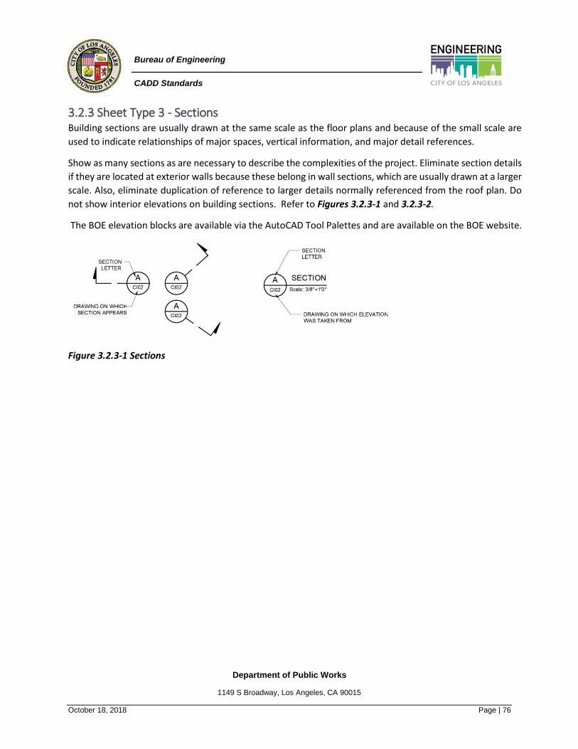
Department of Public Works
1149 S Broadway, Los Angeles, CA 90015
October 18, 2018 Page | 76
Bureau of Engineering
CADD Standards
3.2.3 Sheet Type 3 - Sections Building sections are usually drawn at the same scale as the floor plans and because of the small scale are
used to indicate relationships of major spaces, vertical information, and major detail references.
Show as many sections as are necessary to describe the complexities of the project. Eliminate section details
if they are located at exterior walls because these belong in wall sections, which are usually drawn at a larger
scale. Also, eliminate duplication of reference to larger details normally referenced from the roof plan. Do
not show interior elevations on building sections. Refer to Figures 3.2.3-1 and 3.2.3-2.
The BOE elevation blocks are available via the AutoCAD Tool Palettes and are available on the BOE website.
Figure 3.2.3-1 Sections

Department of Public Works
1149 S Broadway, Los Angeles, CA 90015
October 18, 2018 Page | 77
Bureau of Engineering
CADD Standards
Figure 3.2.3-1 Sections Sheet
Notes:
1. Sections use letters. Do not use “I” and “O” to avoid confusion with “1” and “0”
2. Every Section view letter should be unique within a subset.
3. Information inside the bubble and division line shall remain horizontal, section lines will rotate
around bubble.
4. Section views shall be identified by letter. Every section view letter is unique in each sheet
group.
5. Space between most bottom element in view and label is 2”. 1” is allowed if space requires it.
Center all titles on view horizontally.
6. Use grid system for identification of partial sections. Partial sections are considered Details.
7. Multiple sections views on a sheet should be separated by single divider line(s)

Department of Public Works
1149 S Broadway, Los Angeles, CA 90015
October 18, 2018 Page | 78
Bureau of Engineering
CADD Standards
3.2.4 Sheet Type 4 - Large-Scale Views Large-scale views are drawings reproduced at a larger scale to provide more detailed information that cannot
be accommodated at the smaller-scaled drawing. Refer to Figures 3.2.4-1 and 3.2.4-2.
The BOE elevation blocks are available via the AutoCAD Tool Palettes and are available on the BOE website.
Figure 3.2.4-1 Large-Scale Views
Figure 3.2.4-2 Large-Scale Views Sheet

Department of Public Works
1149 S Broadway, Los Angeles, CA 90015
October 18, 2018 Page | 79
Bureau of Engineering
CADD Standards
Notes:
1. Enlarged views shall be identified by number. Every enlarged view should be unique within a
drawing subset.
2. Information inside the bubble and division line shall remain horizontal.
3. Space between most bottom element in view is 2”. 1” is allowed if space requires it.
4. Center view title within drawing area. Center view frame horizontally and vertically.
5. Enlarged view frame limits, orientation, and shape should match that on the referencing plan
view.
6. Section, elevation, isometric, and detail views should be called out on enlarged views.
3.2.5 Sheet Type 5 - Details Manufactured products should be represented by a simplified outline illustrating all the products listed as
acceptable in the specifications. Details should take into account tolerances that may be listed in the
specifications. Refer to Figure 3.2.5-1 and 3.2.5-2.
The BOE elevation blocks are available via the AutoCAD Tool Palettes and are available on the BOE website.
Figure 3.2.5-1 Details Layout

Department of Public Works
1149 S Broadway, Los Angeles, CA 90015
October 18, 2018 Page | 80
Bureau of Engineering
CADD Standards
Figure 3.2.5-2 Details Notes:
1. Detail grid symbols point directly to the object.
2. Information inside the bubble and division line shall always remain horizontal.
3. Use grid system to identify partial sections. Partial sections are considered details.
4. Use (a-a, b-b) and view type (i.e. PLAN, SECTION, ELEVATION etc.).

Department of Public Works
1149 S Broadway, Los Angeles, CA 90015
October 18, 2018 Page | 81
Bureau of Engineering
CADD Standards
3.2.6 Sheet Type 6 - Schedules and Diagrams Schedules take a tabular form while diagrams are graphic representations. Refer to Figure 3.2.6-1. Both
provide a large amount of information in a limited space. Schedules, as shown in Figure 3.2.6-2, may be
placed either in the specifications or on the drawings.
Figure 3.2.6-1 Diagrams
.
Figure 3.2.6-2 Schedules
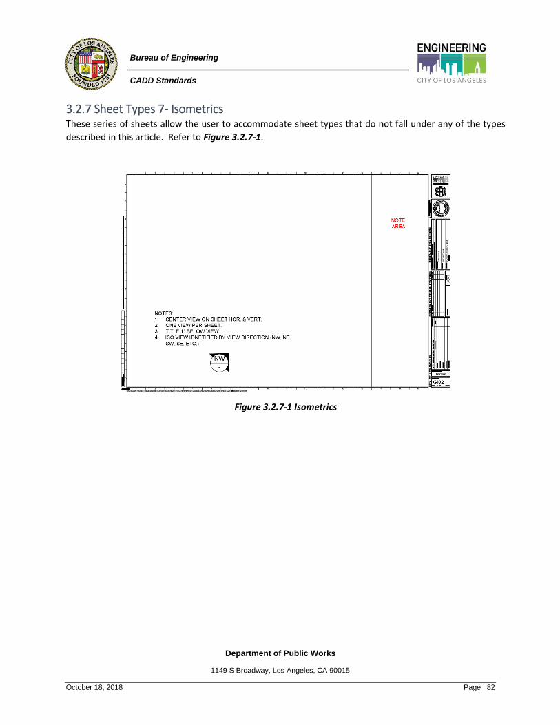
Department of Public Works
1149 S Broadway, Los Angeles, CA 90015
October 18, 2018 Page | 82
Bureau of Engineering
CADD Standards
3.2.7 Sheet Types 7- Isometrics These series of sheets allow the user to accommodate sheet types that do not fall under any of the types
described in this article. Refer to Figure 3.2.7-1.
Figure 3.2.7-1 Isometrics

Department of Public Works
1149 S Broadway, Los Angeles, CA 90015
October 18, 2018 Page | 83
Bureau of Engineering
CADD Standards
3.2.8 Sheet Type 8 - 3D Representations 3D views include axonometric drawings, exploded views, 3D sections, perspectives, and photographs. They
are used to assist the viewer in comprehending complex 3D relationships of shapes. When used to
supplement information and display overall 3D renderings, these types of drawings and images may be
placed on sheet type 9; however, they also may be placed on sheet types 1 - 5 when used to specifically
convey construction details.
3D Representations renderings are to be limited to one view per sheet. The title of the view should be one
inch below the view, and both the view and title are to be centered horizontally and vertically. 3D renderings
may have text callouts, but references are not needed. Refer to Figure 3.2.8-1.
Figure 3.2.8-1 3D Representation Renderings
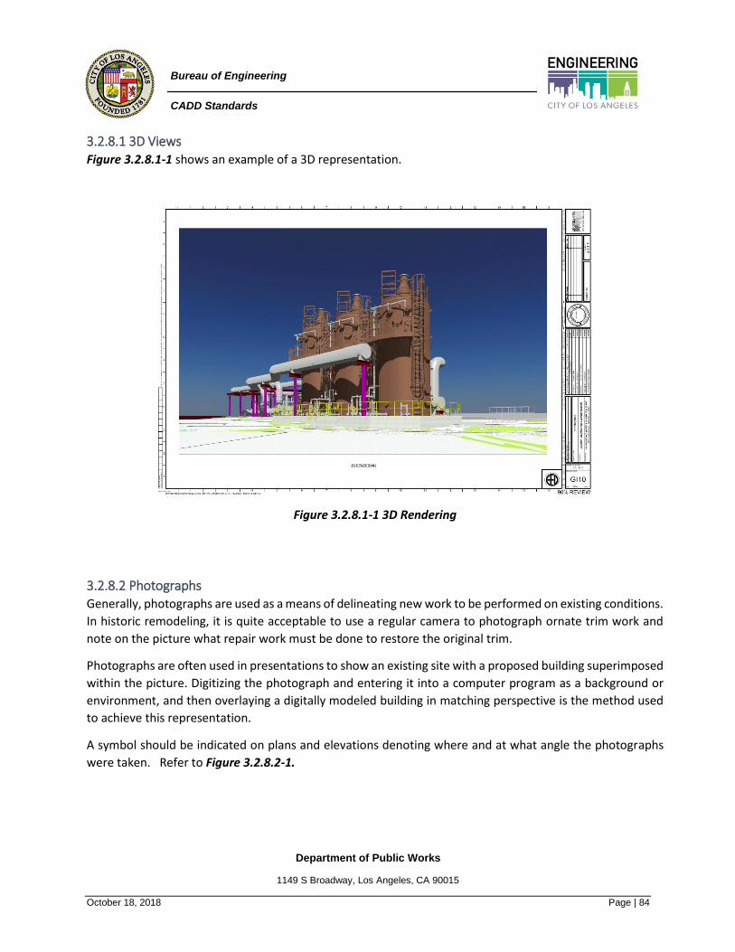
Department of Public Works
1149 S Broadway, Los Angeles, CA 90015
October 18, 2018 Page | 84
Bureau of Engineering
CADD Standards
3.2.8.1 3D Views Figure 3.2.8.1-1 shows an example of a 3D representation.
Figure 3.2.8.1-1 3D Rendering
3.2.8.2 Photographs Generally, photographs are used as a means of delineating new work to be performed on existing conditions.
In historic remodeling, it is quite acceptable to use a regular camera to photograph ornate trim work and
note on the picture what repair work must be done to restore the original trim.
Photographs are often used in presentations to show an existing site with a proposed building superimposed
within the picture. Digitizing the photograph and entering it into a computer program as a background or
environment, and then overlaying a digitally modeled building in matching perspective is the method used
to achieve this representation.
A symbol should be indicated on plans and elevations denoting where and at what angle the photographs
were taken. Refer to Figure 3.2.8.2-1.

Department of Public Works
1149 S Broadway, Los Angeles, CA 90015
October 18, 2018 Page | 85
Bureau of Engineering
CADD Standards
Figure 3.2.8.2-1 Photographs
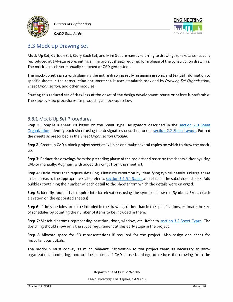
Department of Public Works
1149 S Broadway, Los Angeles, CA 90015
October 18, 2018 Page | 86
Bureau of Engineering
CADD Standards
3.3 Mock-up Drawing Set
Mock-Up Set, Cartoon Set, Story Book Set, and Mini-Set are names referring to drawings (or sketches) usually
reproduced at 1/4-size representing all the project sheets required for a phase of the construction drawings.
The mock-up is either manually sketched or CAD generated.
The mock-up set assists with planning the entire drawing set by assigning graphic and textual information to
specific sheets in the construction document set. It uses standards provided by Drawing Set Organization,
Sheet Organization, and other modules.
Starting this reduced set of drawings at the onset of the design development phase or before is preferable.
The step-by-step procedures for producing a mock-up follow.
3.3.1 Mock-Up Set Procedures Step 1: Compile a sheet list based on the Sheet Type Designators described in the section 2.0 Sheet
Organization. Identify each sheet using the designators described under section 2.2 Sheet Layout. Format
the sheets as prescribed in the Sheet Organization Module.
Step 2: Create in CAD a blank project sheet at 1/4-size and make several copies on which to draw the mock-
up.
Step 3: Reduce the drawings from the preceding phase of the project and paste on the sheets either by using
CAD or manually. Augment with added drawings from the sheet list.
Step 4: Circle items that require detailing. Eliminate repetition by identifying typical details. Enlarge these
circled areas to the appropriate scale, refer to section 3.1.5.1 Scales and place in the subdivided sheets. Add
bubbles containing the number of each detail to the sheets from which the details were enlarged.
Step 5: Identify rooms that require interior elevations using the symbols shown in Symbols. Sketch each
elevation on the appointed sheet(s).
Step 6: If the schedules are to be included in the drawings rather than in the specifications, estimate the size
of schedules by counting the number of items to be included in them.
Step 7: Sketch diagrams representing partition, door, window, etc. Refer to section 3.2 Sheet Types. The
sketching should show only the space requirement at this early stage in the project.
Step 8: Allocate space for 3D representations if required for the project. Also assign one sheet for
miscellaneous details.
The mock-up must convey as much relevant information to the project team as necessary to show
organization, numbering, and outline content. If CAD is used, enlarge or reduce the drawing from the
Department of Public Works
1149 S Broadway, Los Angeles, CA 90015
October 18, 2018 Page | 87
Bureau of Engineering
CADD Standards
preceding phase to generate details. After the drawing is generated, paste on the detail sheet. Refer to the
19.0 Appendix H – Summary of Governing Regulations & Influences for sheet groupings, format, subdivisions,
and numbering. Also, identify standard details to be retrieved from the firm's standard details library, reduce
to 1/4-size, and paste on their respective sheets. Refer to Figures 3.3.1-1 and 3.3.1-2.
Figure 3.3.1-1 Mock-up of a plan sheet.
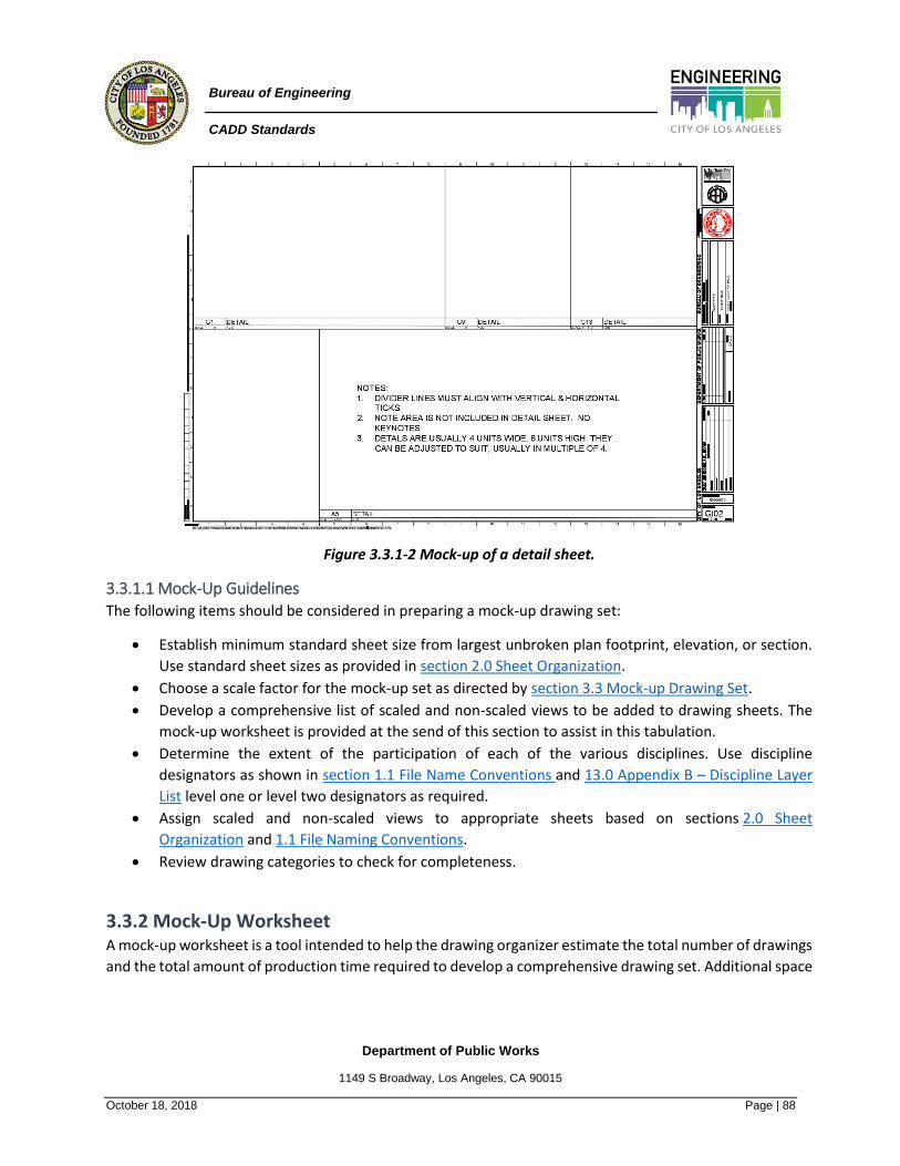
Department of Public Works
1149 S Broadway, Los Angeles, CA 90015
October 18, 2018 Page | 88
Bureau of Engineering
CADD Standards
Figure 3.3.1-2 Mock-up of a detail sheet.
3.3.1.1 Mock-Up Guidelines The following items should be considered in preparing a mock-up drawing set:
• Establish minimum standard sheet size from largest unbroken plan footprint, elevation, or section.
Use standard sheet sizes as provided in section 2.0 Sheet Organization.
• Choose a scale factor for the mock-up set as directed by section 3.3 Mock-up Drawing Set.
• Develop a comprehensive list of scaled and non-scaled views to be added to drawing sheets. The
mock-up worksheet is provided at the send of this section to assist in this tabulation.
• Determine the extent of the participation of each of the various disciplines. Use discipline
designators as shown in section 1.1 File Name Conventions and 13.0 Appendix B – Discipline Layer
List level one or level two designators as required.
• Assign scaled and non-scaled views to appropriate sheets based on sections 2.0 Sheet
Organization and 1.1 File Naming Conventions.
• Review drawing categories to check for completeness.
3.3.2 Mock-Up Worksheet A mock-up worksheet is a tool intended to help the drawing organizer estimate the total number of drawings
and the total amount of production time required to develop a comprehensive drawing set. Additional space

Department of Public Works
1149 S Broadway, Los Angeles, CA 90015
October 18, 2018 Page | 89
Bureau of Engineering
CADD Standards
on the back or another sheet may be needed to list the total number of small-scale details and/or schedules
the project requires. Refer to the Mock-Up Worksheet below.
MOCK-UP WORKSHEET
SHEET
NUMBER
SHEET
NAME
NUMBER OF
VIEWS
LIST OF VIEWS
(Include All
Disciplines)
SCALED
SIZE
NUMBER OF
HOURS PER
SHEET
ASSIGNED
TO:
COST PER
SHEET
TOTAL COST
Department of Public Works
1149 S Broadway, Los Angeles, CA 90015
October 18, 2018 Page | 90
Bureau of Engineering
CADD Standards
4.0 Symbols
The Section includes a full range of standard symbols used throughout the construction industry. Covered in
this Section are standard symbols, their graphic representation, and their role in creating, understanding,
and fulfilling the intent of construction documents. Standard symbols ensure clear and concise
communication among the architect, engineer, owner, contractor, and consultants and are available on
custom BOE AutoCAD Tool Palettes.
4.1 Symbols Scale
BOE Symbols used in drawings are annotative and will adjust to the drawing scale.
4.2 Symbols Classification
Symbols used in drawings are classified in terms of type.
4.2.1 Identity (ID) Identity symbols indicate individual objects and are generally used in all discipline drawings. Such symbols
are valves fire alarms, light fixtures, and electrical outlets. These symbols may be either scale dependent or
independent.
4.2.2 Line (LINE) Line symbols indicate continuous objects and are either single or multiple lines. Walls are usually drawn with
two lines and ducts may be drawn with one or two lines based on the scale of the drawing. Site and building
utilities are drawn with one line with breaks in the line for a letter(s) to identify the utility line. Some lines
are solid, some are dashed, and some combine both. These symbols are scale independent.
4.2.3 Material (MATL) Material symbols graphically indicate certain materials and are used to help the reader differentiate one
material from another. These symbols may be in elevation, vertical, or horizontal section. These symbols
should be used as necessary but not overdone and used where a material begins and ends or changes
direction. Such symbols are used to designate earth, concrete, stone, steel, wood, and insulation. Symbols
are drawn in an appropriate size and scale of the drawn object. A material symbol may change based on the
scale used or the view presented of the object. These symbols can be either scale dependent or independent.
See Figure 4.2.3-1 Material Symbols.

Department of Public Works
1149 S Broadway, Los Angeles, CA 90015
October 18, 2018 Page | 91
Bureau of Engineering
CADD Standards
Figure 4.2.3-1 Material Symbols
4.2.4 Object (OBJ) Object symbols resemble the actual objects being symbolized. Such symbols are doors, some with the
direction of swing indicated, windows, toilet fixtures, and furniture. These symbols are scale dependent.
4.2.5 Reference (REF) Reference symbols refer the reader to information in another area of the set of drawings or give basic
information regarding the drawing or data on the drawing. Such symbols are exterior and interior elevation
indicators, building section indicators, partial building section indicators, and detail indicators. Included with
these symbols are drawing block titles, graphic scales, north indicator, room identifiers, door/borrowed lite
identifiers, window type identifiers, louver type identifiers, wall type identifiers, furniture, fixture and
equipment identifiers, identification device (sign) identifiers, key note identifiers, leaders, dimension lines
with terminators, match lines, and revision clouds with identifiers. These symbols are scale independent.
4.2.6 Text (TEXT) Text that is embedded in symbols are alphanumeric data that is non-changeable when attached to a block,
such as a North direction indicator. Text that is part of a symbol graphically indicates a commonly used word
or words that may be used in notations on drawings, such as ±, ≤ X°. If different tags are necessary, block
attributes are required.
Attributes are changeable text labels or tags that are attached to a block. Each insertion of the block can
have different tag data, making each instance unique. Using symbols as attributes for variable data and text
for static is recommended.

Department of Public Works
1149 S Broadway, Los Angeles, CA 90015
October 18, 2018 Page | 92
Bureau of Engineering
CADD Standards
4.3 Symbols Organization
Symbols are organized by the MasterFormat™ division number and 3-digit extension number, the symbol
type, and the alphabetical order of the symbol description. Refer to 17.0 Appendix F – Symbols Index.
For example, a bathtub is listed in MasterFormat™ Division 22, Plumbing, Section 22 40 00, Plumbing
Fixtures. Although the bathtub may be shown on Architectural floor plans, the bathtub is listed in Division
22, Plumbing. The actual layout of the symbols in the table would be the MasterFormat™ division
number and 3-digit extension number, the symbol type (alphabetized), the symbol description
(alphabetized), and the symbol. Refer to Figure 4.3-1.
• Unique symbol drawing file name (concatenation of MasterFormat™ division and number [without
spaces]) + dash + 3-digit extension number + dash + symbol type + space + symbol description
(abbreviated), e.g., 224000-002-OBJ BATH, EMER
MF NO-3 TYPE DESCRIPTION / DRAWING NAME SYMBOL
DIV 01 GENERAL REQUIREMENTS
224000-002 OBJ BATH / EMER
Figure 4.3-1 Symbol Organization

Department of Public Works
1149 S Broadway, Los Angeles, CA 90015
October 18, 2018 Page | 93
Bureau of Engineering
CADD Standards
5.0 Notations
Construction documents include drawings and specifications, which are meant to be complementary
documents. Drawings convey design intent and may show multiple views, either of the whole project or its
parts. Specifications provide detailed information and instructions concerning the project by setting
requirements for the physical qualities, chemical properties, performance requirements, and standards of
workmanship associated with the manufacture and installation of systems, assemblies, and components.
Drawings: Graphic and textual information organized on a two-dimensional surface for the purpose of
conveying data about a specific portion of a project.
Specifications: Define the qualitative requirements for products, materials, and workmanship on which the
construction contract is based.
To understand more fully the drawings, text—in the form of notes—is added to the illustrations. The notes
may provide:
• information
• identification
• instruction
Drawing notes, as part of the contract documents, have important legal consequences. Just as in creating a
specification section, care must be taken to ensure that drawing notes do not establish a subdivision of the
work; assign portions of the work to subcontractors; or create unintended obligations between the parties
to the design and construction of the work. Terms used within notes should be consistent with terms used
within the specifications. Notes should not include vague references such as "SEE SPECIFICATIONS." They
should be specific as discussed later under Reference Keynotes.
5.1 General Notes / Notice to Contractor
General notes are located within the provided general drawings GI sheets and are available on the custom
BOE Tool Palettes. General notes apply to the entire work and they apply equally to all disciplines and to all
sheets within the drawing set. To repeat them on subsequent sheets or at other locations within the drawing
set it is neither necessary nor desirable. Likewise, general notes do not repeat specification content on the
drawings nor are they repeated within the specifications. Refer to Figure 5.1-1 for a typical layout of the
notes block.
Carefully coordinate general notes with the contents of the project manual and Division 01 specification
sections as shown in Figure 5.1-2. As with the Division 01 sections, the content and requirements expressed
by the general notes should be prepared by the lead designer, then communicated and coordinated with

Department of Public Works
1149 S Broadway, Los Angeles, CA 90015
October 18, 2018 Page | 94
Bureau of Engineering
CADD Standards
other participating design disciplines to avoid repetitive or contradictory language within the notes and
specifications.
Figure 5.1-1 General notes.

Department of Public Works
1149 S Broadway, Los Angeles, CA 90015
October 18, 2018 Page | 95
Bureau of Engineering
CADD Standards
Figure 5.1-2 Notes to Contractor

Department of Public Works
1149 S Broadway, Los Angeles, CA 90015
October 18, 2018 Page | 96
Bureau of Engineering
CADD Standards
5.2 General Discipline Notes
General [discipline] notes appear on the first or 0-Series sheets within a particular design discipline and
apply to all subsequent sheets within that discipline. For example, general civil notes appear on sheet C-001
and apply to all civil sheets within the drawing set.
Because general [discipline] notes apply to drawings of the discipline, they should not be repeated on other
sheets within the discipline. These notes typically provide instruction concerning discipline-specific drafting
conventions or other use of that discipline's drawings. General [discipline] notes do not replicate general
notes. Coordination is necessary to ensure general [discipline] notes are coordinated with the project
information, project requirements, and drafting conventions established within the general notes and may
be presented in more detail elsewhere within the drawings or specifications. Refer to Figures 7.1-1 and 7.3-
1.
General [Discipline] Notes: Notes that apply only to a particular design discipline. Users should provide a
heading for these notes by replacing the [discipline] place holder with the name of the particular design
discipline as in the following examples:
• General Architectural Notes
• General Structural Notes
• General Mechanical Notes
• General Interior Design Notes
Example: TOP OF STEEL ELEVATIONS INDICATED ARE BASED ON A FINISH FLOOR ELEVATION OF 30M (100'-
0")—SEE SHEET C-101 FOR ACTUAL DATUM AND BENCHMARK INFORMATION
5.3 General Sheet Notes
General sheet notes are used to communicate sheet-specific information or instructions. General sheet
notes are tabulated sequentially within the note block. General sheet notes follow the other types of general
notes (general notes or general [discipline] notes) and precede any reference keynotes that may appear in
the note block. Refer to Figures 5.3-1 and 5.3-2. General sheet notes should be written in the imperative
mood and in a streamlined format similar to the preferred specification language presented in The Project
Resource Manual—CSI Manual of Practice (PRM).
For General Sheet Notes, the top three notes shall apply to all projects. The note text shall be left justified
with single spacing between the notes. The margins within the Notes are shall be ¼” along the top and left
sides.

Department of Public Works
1149 S Broadway, Los Angeles, CA 90015
October 18, 2018 Page | 97
Bureau of Engineering
CADD Standards
General Sheet Notes: Notes that apply only to the particular sheet on which they appear.
Example: CONTRACTOR SHALL FIELD VERIFY ALL DIMENSION & LOCATION PRIOR TO ANY DEMOLITION.
Figure 5.3-1 Three types of general notes—general notes, general sheet notes, and general [discipline]
notes.
Figure 5.3-2 General Sheet Notes.

Department of Public Works
1149 S Broadway, Los Angeles, CA 90015
October 18, 2018 Page | 98
Bureau of Engineering
CADD Standards
5.4 Sheet Keynotes
Sheet keynotes are noted within the graphic and notation areas of the drawing block and are to be used on
all projects. They are drawn with a ¼” diameter bubble symbol containing a numeral with leader(s) from the
bubble to the identified item. The bottom of the bubble symbol should always be drawn parallel to the
bottom of the drawing sheet. The numeral for each symbol that appears on the sheet is listed in the sheet's
note block along with a text note that describes the graphic. A unique numeral must be assigned for each
identified item, and the keynotes tabulated sequentially within the note block. The numerals may begin with
1, followed by 2, 3, 4, 5, etc., or other sequential orders (e.g., 7 followed by 12, 31, 33, 45, etc.) Refer
to Figures 5.4-1 and 5.4-2.
Sheet Keynotes: Identify, inform, and instruct without reference to the specifications.
Figure 5.4-1 Sheet keynotes.
Figure 5.4-2 Sheet indicator
Notes:
1. Every division shall approve the use of sheet keynotes.
2. Keynotes are drawn with a circle symbol containing a numeral with leader(s) from the circle to
the identified item.
Department of Public Works
1149 S Broadway, Los Angeles, CA 90015
October 18, 2018 Page | 99
Bureau of Engineering
CADD Standards
3. The numeral for each symbol that appears on the sheet is listed in the sheet’s note block along
with a text note that describes the graphic.
4. A unique numeral must be assigned for each identified item, and the keynotes should be
tabulated sequentially within the note block.
5. Keynotes are annotative and available on the custom BOE AutoCAD Tool Palette <palettename>.
Sheet keynotes follow the listing of any reference keynotes within the note block. Each numeric identifier is
listed in sequential order in the note block with the full text of the note. Sheet keynotes should not be used
to identify items referenced in the specifications.
5.5 Note Hierarchy
The placement of notes within the note block is shown in Figure 5.5-1. If a certain note type is not required,
do not indicate a heading for that note type. Shift the note types upward that would normally be located
beneath the (unused) notes. When laying out note blocks, users should consider the space required at the
bottom of the note block, which is reserved for any applicable key plans. (See sections 3.0 Drawing
Conventions and 2.0 Sheet Organization for recommended key plan location.) Generally, the note block
would be formatted as a single column of notes.
On a small project, the general notes would appear on the first drawing sheet within the set followed by
general [discipline] notes, and general sheet notes. As hierarchical information, the general notes always
appear as the first notes within their note blocks. Refer to Figure 5.5-1.
If more notes are required than will fit in a sheet's single-column note block, the note block should expand
to the left and be formatted to allow multiple columns of notes. Refer to Figure 5.5-1.
On the applicable 0-Series sheets as defined in Module 1 - Drawing Set Organization where they appear, the
general [discipline] notes are the first notes within the sheet's note block(s). An exception to this rule is on
drawing sheets for small projects on which general [discipline] notes follow any general notes and precede
any general sheet notes.
General sheet notes appear at the top of a sheet's note block(s) except for G-Series (e.g., G-001) and 0-Series
(e.g., C-001) sheets where they follow any general notes or general [discipline] notes that may be on those
sheets. Refer to Figure 5.3-1. General sheet notes are numbered sequentially as they are developed.
Note Block: Module or modules where general notes, keynotes, and key plans are located. Refer to section
2.0 Sheet Organization.
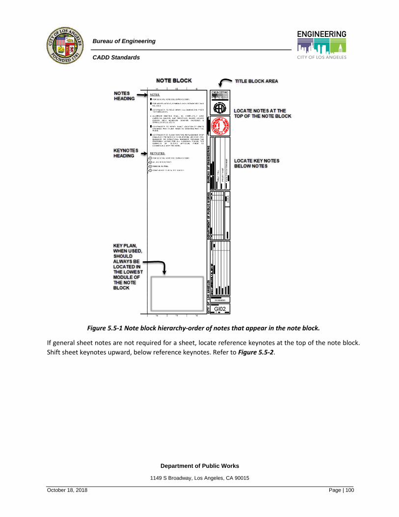
Department of Public Works
1149 S Broadway, Los Angeles, CA 90015
October 18, 2018 Page | 100
Bureau of Engineering
CADD Standards
Figure 5.5-1 Note block hierarchy-order of notes that appear in the note block.
If general sheet notes are not required for a sheet, locate reference keynotes at the top of the note block.
Shift sheet keynotes upward, below reference keynotes. Refer to Figure 5.5-2.

Department of Public Works
1149 S Broadway, Los Angeles, CA 90015
October 18, 2018 Page | 101
Bureau of Engineering
CADD Standards
Figure 5.5-2 Hierarchy of notes in note block.
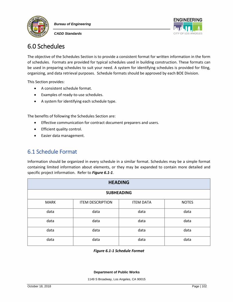
Department of Public Works
1149 S Broadway, Los Angeles, CA 90015
October 18, 2018 Page | 102
Bureau of Engineering
CADD Standards
6.0 Schedules
The objective of the Schedules Section is to provide a consistent format for written information in the form
of schedules. Formats are provided for typical schedules used in building construction. These formats can
be used in preparing schedules to suit your need. A system for identifying schedules is provided for filing,
organizing, and data retrieval purposes. Schedule formats should be approved by each BOE Division.
This Section provides:
• A consistent schedule format.
• Examples of ready-to-use schedules.
• A system for identifying each schedule type.
The benefits of following the Schedules Section are:
• Effective communication for contract document preparers and users.
• Efficient quality control.
• Easier data management.
6.1 Schedule Format
Information should be organized in every schedule in a similar format. Schedules may be a simple format
containing limited information about elements, or they may be expanded to contain more detailed and
specific project information. Refer to Figure 6.1-1.
HEADING
SUBHEADING
MARK ITEM DESCRIPTION ITEM DATA NOTES
data data data data
data data data data
data data data data
data data data data
Figure 6.1-1 Schedule Format

Department of Public Works
1149 S Broadway, Los Angeles, CA 90015
October 18, 2018 Page | 103
Bureau of Engineering
CADD Standards
The format of schedules on drawings is limited by the size of the sheet. Likewise, schedules included in the
specifications are limited by the page size of the project manual. Consider the following when determining
the format and location of schedules:
• Client requirements
• Size
o Drawing block, to fit within the grid of the drawing area
o Drawing area, if the whole sheet is used for the schedule or just the Note Area
o Project Manual page size and relevant specifications
o Row Height
▪ A row height of 0-7/16” (0.4375) is to be used for the heading area of the schedule.
▪ A row height of 0-10/16” (0.6250) is to be used for the subheading area of the
schedule.
▪ A row height of 0-6/16” (0.3750) is to be used for the header area of the schedule.
▪ A row height of 0-9/16” (0.5625) is to be used for the title data area of the schedule.
o Column Width
▪ The column width of the title area of the schedule shall be the entire width of the
schedule.
▪ The column width of the subtitle area of the schedule shall be the entire width of
the schedule.
▪ The column width for the header and data areas of the schedule shall be adjusted
as necessary to fit the data.
• Text Font and Size
o Arial Bold and a text height of 1/4” units shall be used for the heading area of the schedule.
o Arial Bold and a text height of 3/16” units shall be used for the subheading area of the
schedule.
o Arial Regular and a text height of 1/8” units shall be used for both the header and data areas
of the schedule.
• Method of creation
o Generated from CAD model or other computer software
o Manually produced
• Reproduction method
• Degree of reduction or enlargement
• Symbology
• End use
o Permitting requirements
o Job site
• Discipline standard practice

Department of Public Works
1149 S Broadway, Los Angeles, CA 90015
October 18, 2018 Page | 104
Bureau of Engineering
CADD Standards
6.1.1 Heading The main subject or title of a schedule is described by the schedule heading. Schedule titles are not project
specific, so names should be general enough to use across projects.
6.1.2 Subheading If necessary, a secondary title or subheading can be added to further describe the schedule. Schedule
subtitles also are not project specific so names should be general enough to use across projects.
6.1.3 Mark Column Schedules have a Mark column as the first identifier header column at the far left of the schedule. The mark
may be alphanumeric or can include a graphic symbol relating to the item's use on the drawings. In a large
or wide schedule, an additional mark column located on the right side of the schedule can improve
readability.
Schedules that serve a similar purpose across disciplines (such as a tie-in symbol) should be used consistently
for all disciplines. Schedule symbols should not conflict with other general symbology.
6.1.4 Item Description Column The item description is the name or identification of each item in the header provided with a separate mark
in the schedule. Consistent names should be established for use across projects.
6.1.5 Item Data Column The item data column or columns in the header can be added as necessary to convey the necessary schedule
information.
6.1.6 Notes Column The notes column in the header is a special type of distinguishing feature column used to locate special
remarks about items in the schedule that do not necessarily warrant their own separate column identifier.
It is usually located at the far-right side of the schedule.
The notes column usually contains a unique or special description about a specific item in the identifier row.
A note may be written as a complete sentence or just descriptive words. A note may also be a key letter or
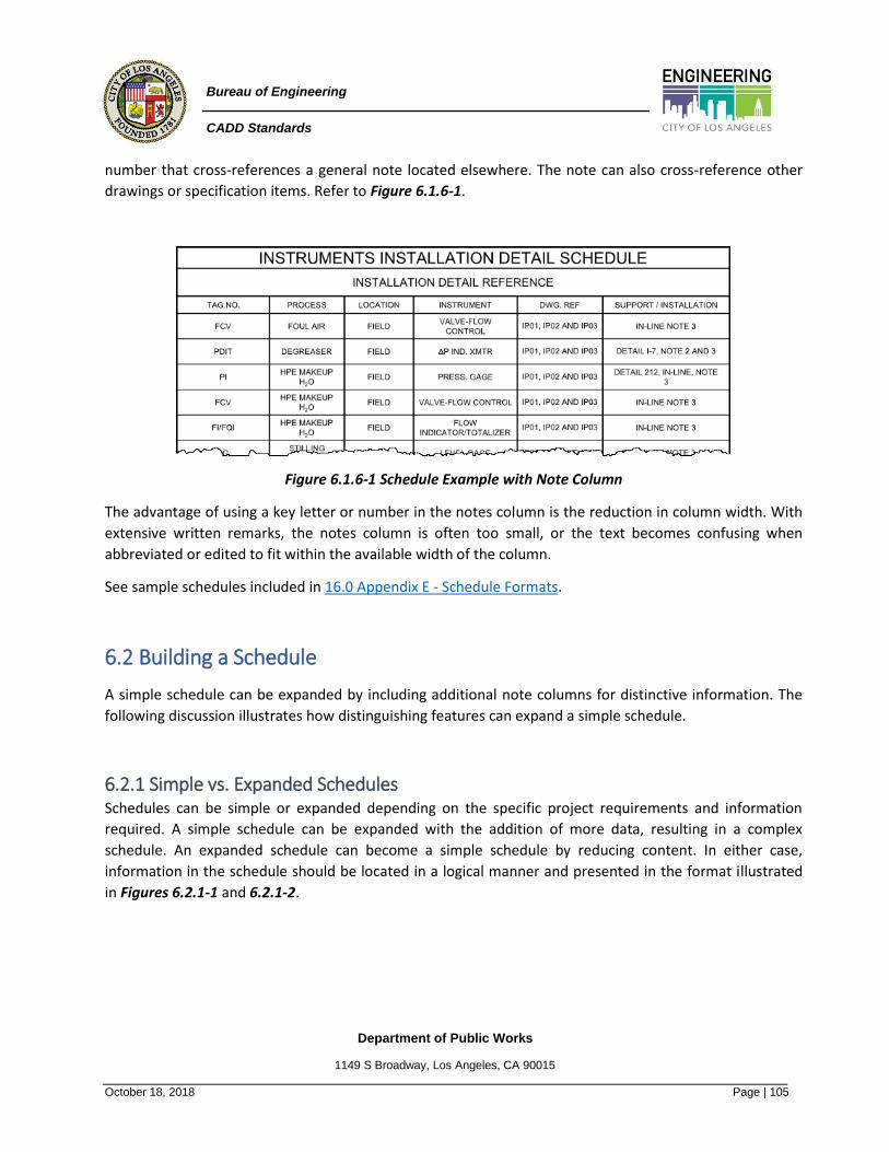
Department of Public Works
1149 S Broadway, Los Angeles, CA 90015
October 18, 2018 Page | 105
Bureau of Engineering
CADD Standards
number that cross-references a general note located elsewhere. The note can also cross-reference other
drawings or specification items. Refer to Figure 6.1.6-1.
Figure 6.1.6-1 Schedule Example with Note Column
The advantage of using a key letter or number in the notes column is the reduction in column width. With
extensive written remarks, the notes column is often too small, or the text becomes confusing when
abbreviated or edited to fit within the available width of the column.
See sample schedules included in 16.0 Appendix E - Schedule Formats.
6.2 Building a Schedule
A simple schedule can be expanded by including additional note columns for distinctive information. The
following discussion illustrates how distinguishing features can expand a simple schedule.
6.2.1 Simple vs. Expanded Schedules Schedules can be simple or expanded depending on the specific project requirements and information
required. A simple schedule can be expanded with the addition of more data, resulting in a complex
schedule. An expanded schedule can become a simple schedule by reducing content. In either case,
information in the schedule should be located in a logical manner and presented in the format illustrated
in Figures 6.2.1-1 and 6.2.1-2.
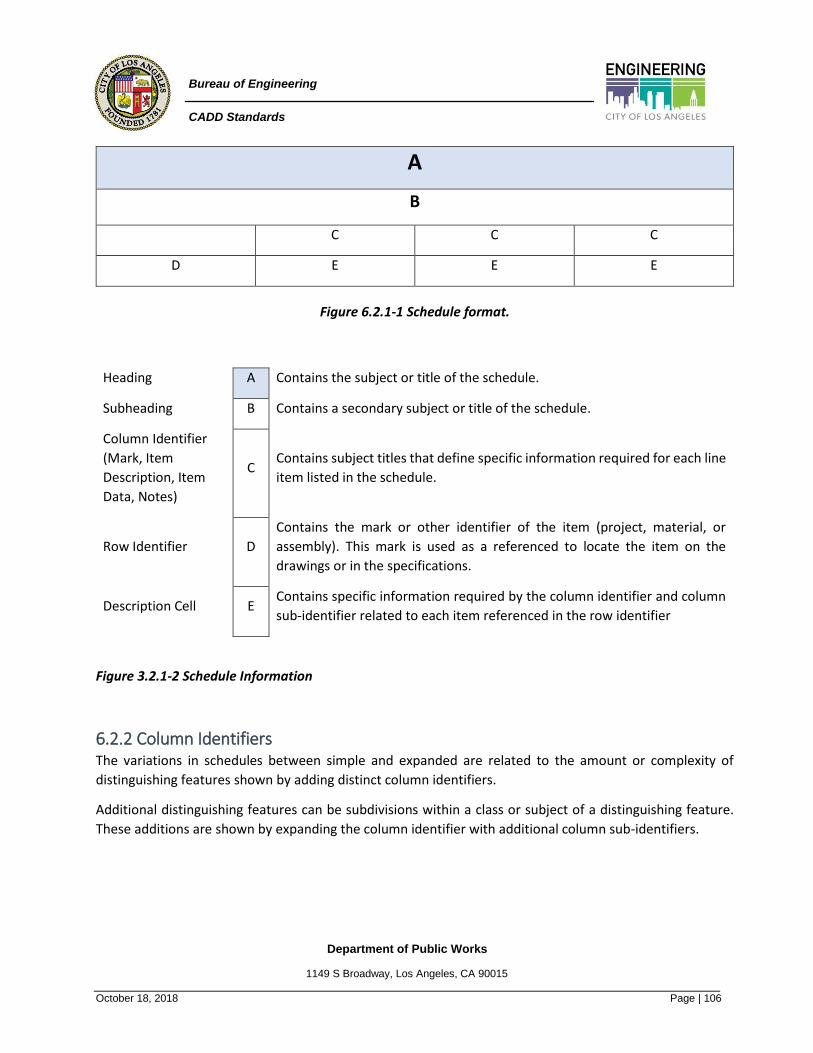
Department of Public Works
1149 S Broadway, Los Angeles, CA 90015
October 18, 2018 Page | 106
Bureau of Engineering
CADD Standards
A
B
C C C
D E E E
Figure 6.2.1-1 Schedule format.
Heading A Contains the subject or title of the schedule.
Subheading B Contains a secondary subject or title of the schedule.
Column Identifier
(Mark, Item
Description, Item
Data, Notes)
C Contains subject titles that define specific information required for each line
item listed in the schedule.
Row Identifier D
Contains the mark or other identifier of the item (project, material, or
assembly). This mark is used as a referenced to locate the item on the
drawings or in the specifications.
Description Cell E Contains specific information required by the column identifier and column
sub-identifier related to each item referenced in the row identifier
Figure 3.2.1-2 Schedule Information
6.2.2 Column Identifiers The variations in schedules between simple and expanded are related to the amount or complexity of
distinguishing features shown by adding distinct column identifiers.
Additional distinguishing features can be subdivisions within a class or subject of a distinguishing feature.
These additions are shown by expanding the column identifier with additional column sub-identifiers.

Department of Public Works
1149 S Broadway, Los Angeles, CA 90015
October 18, 2018 Page | 107
Bureau of Engineering
CADD Standards
A simple schedule can present distinguishing features using a single-tier column identifier. For
example, Figure 6.2.2-1 illustrates a simple conduit Line Summary schedule with a single column identifier
for the overall category of line number.
Figure 6.2.2-1 Single-tier Column Identifier.
Basic examples of double-tier and triple-tier column identifier are shown in Figures 6.2.2-2, 6.2.2-3 and
6.2.2-4.
A
B B B
B B C C C C C
D E E E E E E E
Figure 6.2.2-2 Double-tier Column Identifier
A
B B B B
C C C C
C C C C C C C C
D E E E E E E E E E
Figure 6.2.2-3 Triple-tier Column Identifier

Department of Public Works
1149 S Broadway, Los Angeles, CA 90015
October 18, 2018 Page | 108
Bureau of Engineering
CADD Standards
Heading A Contains the subject or title of the schedule.
Column Identifier
B Contains subject titles that define specific information required for each line item listed in the schedule.
Column Sub-Identifier
C The column sub-identifier lists additional titles for more detailed information to be provided under a subject in the column identifier. This level of information can be further divided to allow for triple-tier column identifiers when necessary.
Row Identifier
D Contains the mark or other identifier of the item (project, material, or assembly). This mark is used as a reference to locate the item on the drawings or in the specifications.
Description Cell
E Contains specific information required by the column identifier and column sub-identifier related to each item referenced in the row identifier.
Figure 6.2.2-4 Double-tier / Triple-tier Column Identifier
Department of Public Works
1149 S Broadway, Los Angeles, CA 90015
October 18, 2018 Page | 109
Bureau of Engineering
CADD Standards
7.0 Terms & Abbreviations
Establishes guidelines for consistent terminology used in the construction industry. Consistent terms ensure
clear and concise communication among the architect, owner, contractor, and consultants. The purpose of
this Module is to provide a standard for construction document terms and abbreviations.
The Terms and Abbreviations section provides the following:
• A consistent standard of communication in construction documents.
• A searchable list of common terms and abbreviations used in the construction industry.
• Consistent spelling of terms and abbreviations.
• Notes on common use and non-preferred terminology.
7.1 Terms
Notes:
1. All terms are standardized in the GI sheets.
2. For projects that only involve one or two disciplines, the GI sheets should be updated to only
include the necessary abbreviations.
7.2 Abbreviations
Notes:
1. All abbreviations are standardized in the GI sheets.
2. For projects that only involve one or two disciplines, the GI sheets should be updated to only
include the necessary abbreviations.
Department of Public Works
1149 S Broadway, Los Angeles, CA 90015
October 18, 2018 Page | 110
Bureau of Engineering
CADD Standards
8.0 Layer Naming Convention
Layers provide a method by which drawing information is logically organized. It also provides a means for
global changes or updates to the entities that exist in layers. Layers control various object characteristics.
Proper use of layers gives control over the drawing files on-screen display and finished plotted product
appearance. Efficient use of layers reduces document preparation time and improves design document
coordination.
Notes:
1. Layering shall be as directed in Technical Directive 4.0 CADD Standards Layer Guidelines and
associated 13.0 Appendix B – Layer Guidelines.
2. All projects starting after June 1, 2017 must use new layer templates.
3. Jack Cook is assigned as the Layer Manager for EED.
8.1 Layer Properties
Layers control the following properties:
• On/Off
• Freeze/Thaw
• Lock/Unlock
• Color
• Linetype
• Lineweight
• Transparency
• Plot Style
• Plot/Do Not Plot
• Viewport Overrides
• Description
On/Off and Freeze/Thaw are similar, but not the same. Generally, turning Off and Freezing layers should be avoided.
Except in few situations, individual object properties should never deviate from “ByLayer”.
LAYER “0” AND “DEFPOINTS”
There are two layers with special properties in AutoCAD Layer “0” and “DEFPOINTS”.

Department of Public Works
1149 S Broadway, Los Angeles, CA 90015
October 18, 2018 Page | 111
Bureau of Engineering
CADD Standards
All block entities used in a symbols library should be created on Layer “0”. This allows the symbol to be inserted into other drawings with dynamic behavior, as it will take on the properties of the active layer on which it is inserted. Nothing else should be placed in Layer “0”. Do Not Set Layer “0” to Off, Frozen, or NoPlot.
“DEFPOINTS” is for any entity that is not intended to plot. Do not create a special “No Plot” layer.
Layer “0” and “DEFPOINTS” should maintain color 7 (White).
8.1.2 Layer Name Format The Bureau of Engineering (BOE) has adopted the standard created by AIA and the NCS. The majority of
layers used are incorporated into a template by discipline located on the Division CADD server and the
Bureau of Engineering website, however, situations will arise when the user must create a layer. The
following explains the layer naming format to be followed.
Layer names are comprised of data fields, separated by dashes. These fields are populated by coded
abbreviations, most of which are logical and easily deciphered by AEC professionals. Each field is designed
to contain either one, two or four alphanumeric characters. All letters are CAPITAL.
Example:
This layer name describes Civil roadway linework for a new curb.
There are four defined layer name data fields:
• Discipline Designator
• Major Group
• Minor Group
• Status
Not all data fields are mandatory per NCS guidelines & BOE standards.

Department of Public Works
1149 S Broadway, Los Angeles, CA 90015
October 18, 2018 Page | 112
Bureau of Engineering
CADD Standards
8.1.3 Discipline Designator, LEVEL 1 A mandatory one-letter character code which refers to the category of subject matter contained on a
specified layer. For a complete list of Discipline Designators see section 13.1 Discipline Designators in 14.0
Appendix C – Discipline Layer List and shown below in Figures 8.1.3-1 and 8.1.3-2.
LEVEL 1 DISCIPLINE DESIGNATORS
A Architectural B Geotechnical C Civil D Process E Electrical F Fire Protection G General H Hazardous Materials I Interiors J Not Used K Not Used L Landscape M Mechanical N Not Used O Operations P Plumbing Q Equipment
R Resource S Structural T Telecommunications The first discipline designator shown is
mandatory. This example shows a layer
belonging to the Architectural discipline.
U Not Used V Survey / Mapping W Energy Distributed X Other Disciplines Y Not Used Z Contractor / Shop Drawings
Figure 8.1.4-1 Discipline Designators
Figure 8.1.4-2 Discipline Designator Level 1
Note: These Discipline codes should not be deviated from. Other fields offer flexibility, to address use specific
needs.

Department of Public Works
1149 S Broadway, Los Angeles, CA 90015
October 18, 2018 Page | 113
Bureau of Engineering
CADD Standards
8.1.4 Major Group A mandatory four-letter character code identifying a major system, such as ROAD, WALL, BLDG, etc. A Major
Group can be combined with any prescribed Discipline Designator. Most of the abbreviated codes are easily
deciphered without further explanation.
If a major group name does not logically require four characters, a tilde “~” is used to maintain the four
character requirement.
The NCS provides a comprehensive list of Major Group codes for reference
The Major Group field highlighted in the layer shown in Figure 8.1.4-1
is mandatory.
Figure 8.1.4-1 Major Group
8.1.5 Minor Group A set of four-letter character codes to further define the layer; for example, a Minor Group to further define
a ROAD layer would be CURB or WALK. Second, third and fourth minor groups are also optional to further
define layers. The BOE has decided to minimize the use of optional Third & Fourth Minor groups in its layer
naming convention.
At least one Minor Group code is mandatory for BOE layer naming.
If a minor group name does not logically require four characters, a tilde “~” is used to maintain the four-
character requirement.
The NCS provides a comprehensive list of Minor Group codes for reference
For example, in Figure 8.1.5-1,
A-WALL-FULL denotes Architectural, Wall, Full-height.
Figure 8.1.5-1 Minor Group
A second minor group may be used for still further delineation of the data contained on a layer.
For example, in Figure 8.1.5-2, A-WALL-FULL-TEXT
indicates Architectural, Wall, Full-height, Text.
Figure 8.1.5-2 Second Minor Group

Department of Public Works
1149 S Broadway, Los Angeles, CA 90015
October 18, 2018 Page | 114
Bureau of Engineering
CADD Standards
8.1.6 Status (phase) An optional one-character field which defines the layer Status or Phase. This designator differentiates
phases of work and is only needed when phases of work must be differentiated. The most commonly used
Status codes are shown in Figure 8.1.6-1.
STATUS FIELD CODES
Code Description Code Description
A Abandoned 1 Phase 1
D Existing to demolish 2 Phase 2
E Existing to remain 3 Phase 3
F Future work 4 Phase 4
M Items to be removed 5 Phase 5
N New work 6 Phase 6
T Temporary work 7 Phase 7
X Not in contract 8 Phase 8
1-9 Phase numbers 9 Phase 9
Figure 8.1.6-1 Status Codes
Note: Status codes are not necessary for labels, dimensions, and hatching.
The example layer in Figure 8.1.6-2 below shows optional Status field code.
Figure 8.1.6-2 Example Status Code

Department of Public Works
1149 S Broadway, Los Angeles, CA 90015
October 18, 2018 Page | 115
Bureau of Engineering
CADD Standards
8.2 Drawing View Layer List
8.2.1 Drawing View Field Codes The Drawing View field codes are specialized codes for layers that are organized primarily by drawing type,
rather than by major building system. The field codes DETL, ELEV, and SECT also may be used as Minor Group
field codes to modify a major building system.
For data sets that are organized by drawing type, an optional alphanumeric Minor Group field code, ANNN,
is prescribed to further distinguish drawings within a single CAD file. This Minor Group may be used ONLY to
modify the prescribed Drawing View Major Groups; it may not be used to modify any other Major Group.
The format of ANNN also is prescribed. It must consist of a single alphabetic character followed by a three-
digit number between 001 and 999. The definition of ANNN is not prescribed; it must be defined by the user.
The definition must be documented on the NCS Compliance Disclosure Statement for the project on which
it is used.
The Minor Group field codes IDEN, MBND, MCUT, OTLN, and PATT may be used to modify any Major or
Minor Group in the Layer List. The definitions of these prescribed field codes cannot be changed. See sections
8.1.4 Discipline Designator, Level 2 and 8.1.5 Major Group for rules and options governing the use of field
codes.
8.2.2 Drawing View Layer Names
Layer Name Description
□□-DETL Detail
□□-ELEV Elevation
□□-SECT Section
□□-□□□□-ANNN Drawing View Major Group: optional number (A = letter, NNN =
number between 001 and 999)
□□-□□□□-ANNN-IDEN Drawing View Major Group: optional number: identification tags
□□-□□□□-ANNN-MBND Drawing View Major Group: optional number: material beyond cut
□□-□□□□-ANNN-MCUT Drawing View Major Group: optional number: material cut by the
view
□□-□□□□-ANNN-OTLN Drawing View Major Group: optional number: outline
□□-□□□□-ANNN-PATT Drawing View Major Group: optional number: textures and hatch
patterns

Department of Public Works
1149 S Broadway, Los Angeles, CA 90015
October 18, 2018 Page | 116
Bureau of Engineering
CADD Standards
8.3 Annotation Layer List
Annotation is typically associated with the respective Discipline designator and ANNO major group code.
Annotation layers contain text, dimensions, notes, sheet borders, section and detail references, match lines,
tables, titles, etc.
The Layer Names shown below provide examples for using Minor Group field codes for annotation. These
Minor Groups may be used to modify any Major or Minor Group in the Layer List. See all sections in 8.1
Layer Properties for complete rules and options governing the use of Major and Minor Group field codes.
8.3.1 Annotation Layer Names
The following are typical Minor Groups used by BOE to define the ANNO Major Group:
Layer Name Description
C-ANNO-BRNG Bearings and distance labels (survey coordinates)
C-ANNO-DIMS Dimensions
C-ANNO-IDEN Identification tags
C-ANNO-LABL Labels
C-ANNO-LEGN Legends, symbol keys
C-ANNO-LOGO Company logo
C-ANNO-MARK Markers, break marks, leaders
C-ANNO-MATC Match lines
C-ANNO-NOTE Notes
C-ANNO-REDL Redlines
C-ANNO-REFR External References (Xref’s)
C-ANNO-REVC Revision clouds and notes
C-ANNO-SCHD Schedules
C-ANNO-STMP Professional stamps
C-ANNO-SYMB Reference symbols
C-ANNO-TABL Data tables
C-ANNO-TEXT Text
C-ANNO-TITL Drawing or detail titles
C-ANNO-TTLB Border and title block

Department of Public Works
1149 S Broadway, Los Angeles, CA 90015
October 18, 2018 Page | 117
Bureau of Engineering
CADD Standards
8.4 Layer Colors
Layer colors should be assigned using the logic of the actual ‘real world’ colors of the object when possible,
for example:
• Potable Water: a shade of blue
• Sewer Water: a shade of brown
• Storm Water: a shade of blue-green
• Recycled Water: a shade of light purple (purple pipe)
• Trees and Vegetation: a shade of green
Users have the flexibility in choosing colors for items that aren’t physically represented in the ‘real world’ or
to avoid having all elements the same color such as in electrical systems where the ‘real world’ conditions
may all be the same color.
Most text and dimensioning should be set to Color 7 (white).

Department of Public Works
1149 S Broadway, Los Angeles, CA 90015
October 18, 2018 Page | 118
Bureau of Engineering
CADD Standards
8.5 Creating a New Layer
A new layer should only be created after an exhaustive search to find a layer in the existing template. If none
is found, follow the conventions described in these guidelines to conceive an appropriate 4-character
abbreviation, and a logical corresponding layer color. See BOE Lineweight and Linteype standards for use in
defining other layer properties.
8.5.1 Adding New Layers to the Template When a user finds they need to create the same layer on multiple projects, the user should communicate
that to the Discipline Layer Manager so it can be added to the BOE template file. The Layer Managers should
also periodically reach out to CADD operators and discuss the need for amending the layer template.
Individual Discipline Layer Templates are managed by the following BOE Divisions:
Discipline Division Email Phone
Architectural ARC
Civil WCE
Electrical EED [email protected] 310-648-6218
Geotechnical GEO
Landscape ARC
Mechanical EED [email protected] 310-648-6218
Plumbing EED [email protected] 310-648-6218
Process EED [email protected] 310-648-6218
Structural SED
Survey SUR

Department of Public Works
1149 S Broadway, Los Angeles, CA 90015
October 18, 2018 Page | 119
Bureau of Engineering
CADD Standards
9.0 Codes
This Section establishes guidelines for consistency in identifying necessary regulatory information to be
shown in the construction documents. This is needed to facilitate the design process and the permit
application process.
This Section:
• Identifies the information necessary for code research during design.
• Identifies the type of general regulatory information that should appear in the construction
documents.
• Identifies the location of the general regulatory information in the drawing set and on specific
individual sheets.
• Provides standard graphic conventions for incorporation in the drawing portion of the construction
documents.
• Facilitates and expedites the building permit (plan review) application process.
This Section provides the framework necessary to understand the complexities of the project cycle relative
to regulatory requirements. Identifying regulatory issues is integrally tied to all phases of the project cycle,
including Planning, Design, Bidding, Construction, and Post Construction (Occupancy and Use of the
completed project). The planning and design phases are especially important as this is when critical
regulatory information must be identified and located in the construction documents. Inclusion of this
information facilitates the permit application process, as well as Identifying the necessary information to be
submitted for a plan review.
Codes are only a part of the regulatory requirements for which the design professional must maintain
compliance. Accordingly, this module includes aspects of regulatory compliance such as zoning,
environmental (e.g., EPA), and federal (e.g., ADA), in addition to code compliance. The relevant information
is presented as follows:
• Identification of regulatory information in the construction documents.
o Type of information to be included in the construction documents
o Location and format of information in the construction documents
• The plan review process.
• Overview of regulatory information.
• The design process.
Department of Public Works
1149 S Broadway, Los Angeles, CA 90015
October 18, 2018 Page | 120
Bureau of Engineering
CADD Standards
9.1 Identification of Regulatory Information
Building codes include anywhere from 3,300 to 5,000 sections of code requirements. It is very difficult to
identify and evaluate compliance with each and every section in the drawing set. This portion of the module
identifies some of the key criteria to be included in the construction documents to facilitate the design
process, which will expedite the plan review. The efficiency of a plan review, like any other repeated process,
may be improved if a consistent system or technique is established. To this end, the design professional must
provide the necessary information in the construction documents and present the information so it is readily
identifiable. A standardized presentation will expedite the plan review process and, ultimately, the issuance
of the building permit.
Local jurisdictions often establish their own policy regarding regulatory items that must be shown in the
construction documents. Unique local jurisdictional amendments may also emphasize the importance of
certain code criteria over other criteria. Regardless, this section of the module will provide a generic
framework regarding:
• What regulatory issues will be provided.
• Where this information should be located.
• How it should be presented.
The codes cover myriad requirements. Grouping these requirements by category to determine the best
location for the information as well as how to present it is often necessary. Included in these categories are
specific relationships among regulatory issues. These relationships must be noted as they may impact the
placement of information on the drawings. Additionally, the size and complexity of the project may dictate
the placement of the regulatory information. For example, a small stand-alone grocery store will probably
not have a dedicated drawing regarding code requirements (such as GI-102 Code Summary), while one may
be included in a multistory office building. Therefore, determining which drawing(s) should include this
information is necessary.
9.2 The Plan Review Process
An efficient, carefully executed plan review is vital to maintain health, safety, and public welfare. Maintaining
these standards, however, requires a combined effort of the local jurisdiction as well as the design
professional. To perform a review of the construction documents, the documents must show the necessary
information. The design professional's responsibility is to identify what is required and how it is to be shown
in the construction documents.
The plan review process can be more effective and efficient if a formal procedure is followed. In addition, a
preliminary review involving an informal meeting is always helpful to set the stage for an efficient procedure.

Department of Public Works
1149 S Broadway, Los Angeles, CA 90015
October 18, 2018 Page | 121
Bureau of Engineering
CADD Standards
Correctly completed application forms and construction documents (including supporting data such as
structural calculations) will expedite the process.
The following indicates the general milestones of the regulatory process:
• Construction documents and permit applications received.
• Applicable regulations identified.
• Compliance with regulations verified.
• Construction documents approved.
• Permit issued.
• Project inspected.
• Certificate of Occupancy/Completion issued.
The appropriate application forms and construction documents are typically filed on behalf of the owner.
For the design professional to evaluate the requirements of the local jurisdiction, understanding the plan
review process is important. With increases in technology, some jurisdictions are employing an electronic
code review process. This is intended to expedite the process by enabling the information to be transmitted
directly to the reviewer. This process also allows for real-time responses to be transmitted from the reviewer
to the design professional. The viability of an electronic review process should be coordinated in advance
with the local jurisdiction. Additionally, third-party plan review services, such as those offered by the model
code groups, are often used to expedite the process whenever the authority having jurisdiction does not
have the expertise or staff to perform such reviews. Note that the final authority to approve the construction
documents and issue the permit rests with the local authority.
Depending on the scope and complexity of the project, using a phased series of reviews may be more
expeditious. This typically takes the form of an early review where the drawings are still in progress but are
of sufficient detail for a partial permit such as a foundation permit. This process includes a review of the
building occupancy, height and area, fire protection requirements, and preliminary egress considerations. It
also includes a review of the foundation drawings, including the applicable structural loading criteria needed
to design and detail the foundation. This partial permit, in turn, allows for the excavation and foundation
construction to proceed while the final construction documents are being finished. Once completed, the
final construction documents would be submitted for a final building review.
The building permit will typically not be issued until construction documents have been reviewed and
approved for regulatory compliance. This includes phased permits.
The review of shop drawings is another type of phased review. This procedure results in a separate review,
often after the building permit is issued. Such reviews are necessary because preparing construction
documents can be fragmented and may not provide some necessary detailed information to ascertain code
compliance. Roof truss drawings are a good example. The construction drawings may indicate a certain type

Department of Public Works
1149 S Broadway, Los Angeles, CA 90015
October 18, 2018 Page | 122
Bureau of Engineering
CADD Standards
of truss, but the detailed drawings are developed by the contractor as part of a separate review package that
occurs while the project proceeds.
Often, the process entails the use of a checklist that identifies specific sections in the code. The plan reviewer
evaluates each section against the submitted construction documents. This often results in a correction list
that identifies the deficiencies noted in the review. Once resolved, the permit can be issued.
The plan reviewer is responsible for evaluating construction documents with respect to a code and noting
the plan's deficiencies or code violations (with the appropriate code sections). It is not the plan reviewer's
function to recommend design changes to secure code compliance. Nevertheless, an informal discussion of
the plan examination results, with an interpretation of particular code provisions, will improve the dialogue
between the building department and the design professional. Matters of interpretation should be
documented as part of the permit process to create a comprehensive record for approval or rejection of the
construction documents. Occasionally, matters of interpretation can become contentious. When this occurs,
local code officials may seek the opinion of third-party agencies, such as the model code groups. Again, the
authority to enforce and interpret the code rests ultimately with the local authority. Matters of dispute are
sometimes forwarded to the local board of appeals for resolution. Where boards of appeal do not exist, state
boards or agencies may resolve disputes. Final resolution may be through the judicial system.
9.2.1 Plan Review and Inspections The owner is legally obligated to correct the situation if the field inspector discovers a code violation, even
if the violation is apparent on the approved construction documents. This again points out the need for a
competent and thorough plan examination coupled with adequate information on the drawings. To expect,
or even anticipate, that code violations will be discovered in the field places an unnecessary burden on the
inspector. Resolving field problems often causes construction delays and increased costs. There may also be
penalties incurred for some code violations. The time to find nonconformity with the code is in the plan
review stage.
A frequently overlooked aspect of a plan review is that of the special inspection. It is a plan review item and
an inspection item. The special inspection provisions in the codes identify additional third-party inspections
for which the owner is responsible. Inspection of fabricators is an example. The building inspector relies on
third-party inspection reports for those items that are not constructed on the site. During the project’s plan
review stage is where those items for which special inspections will be performed and the agency responsible
must be identified.
Department of Public Works
1149 S Broadway, Los Angeles, CA 90015
October 18, 2018 Page | 123
Bureau of Engineering
CADD Standards
9.3 Overview of Regulatory Information
A model code is a written set of regulations that provides the means for exercising reasonable control over
construction and is available for adoption by cities, counties, states, or countries, with such changes as may
be desirable or legal for local needs. It establishes minimum quality and performance criteria for the
materials and methods regulated by the code. For many materials and methods, the code relies on
referenced standards to provide these criteria. The referenced standards are an enforceable extension of
the code. Standards supplement the code by setting forth conditions or requirements that a material or
method must meet, thereby providing an acceptable level of safety for building occupants. To comply with
the provisions of the model code, a material or method must meet the requirements of the referenced
standard. Material referenced standards are often used as the basis by which a product is labeled. This label,
which is identified on the product, includes information such as name of the manufacturer, function of the
product, and name of the approved agency that conducted the applicable tests.
A standard is a published technical document that represents an industry consensus on how a material or
assembly is to be designed, manufactured, tested, or installed so that a specific level of performance is
obtained. Standards are primarily developed by industry organizations and professional associations
incorporating the views of interested parties. A standard is developed in response to an identified need and
typically contains information based on many years of testing and research.
A standard is not intended to be used as primary law but as a secondary authoritative reference. While a
model code becomes law when it is adopted by a jurisdiction, a standard only becomes law to the extent to
which it is referenced in a model code.
Standards can generally be grouped into four categories:
• Materials
• Design
• Installation
• Testing
The following is an example of each of the four types of standards. The list includes the type of standard, the
standard writing organization, and the scope and application of the standard.
Material: American National Standards Institute
ANSI A208.1, Particleboard
The standard includes definitions, dimensional tolerances, and physical and mechanical
property requirements for different grades of particleboard.
Design: International Code Council
ICC A117.1, Accessible and Usable Buildings and Facilities

Department of Public Works
1149 S Broadway, Los Angeles, CA 90015
October 18, 2018 Page | 124
Bureau of Engineering
CADD Standards
The standard includes technical design criteria for making sites, facilities, buildings, and
elements accessible to those with disabilities.
Installation: National Fire Protection Association
NFPA 13, Installation of Sprinkler Systems
The standard includes the installation requirements for automatic fire sprinkler systems.
Testing: American Society for Testing and Materials
ASTM E119, Test Methods for Fire Tests of Building Construction and Materials
This standard is a fire-test response standard intended to register the fire performance of a
given assembly for a period of fire exposure.
A referenced standard becomes an enforceable part of the code to the extent and scope as referenced in
the text of the code itself. The listing of applicable standards, along with their specific edition, title, and the
sections that reference the standard are typically included in the code's last chapter before any appendices.
9.3.1 State/Local Codes and Amendments The model codes were developed to ease the burdens of state and local governments by providing a set of
regulations readily available for adoption. Most states have adopted a model code without modifications.
Other states and local jurisdictions have adopted a model code with modifications; still others have chosen
to develop their own unique set of regulations. When this occurs, the amendments are often centered on
the administrative provisions of the code. Typically, this is a response to local administrative procedures,
which may be unique to a jurisdiction and, therefore, are not covered in the model code. Technical changes
to the model codes also may occur through the amendment process. For example, jurisdictions with limited
fire-fighting capabilities may modify the sprinkler requirements in the code to gain the benefits of sprinkler
protection in a building that would otherwise not require sprinklers.
9.3.2 Federal Regulations There are numerous federal agencies, each with a specified mission and rule-making authority. Some of the
regulations affect building design and others do not. The design professional must be cognizant of
regulations other than those published in the adopted code. The following are examples of regulations that
may impact the project.
ADA: In 1990, Congress passed the Americans with Disabilities Act (ADA). This act covers employment
discrimination, public transportation, public accommodations, and telecommunications. Of particular
interest to design professionals is Title III and the ADA Accessibility Guidelines (ADAAG) developed by the
U.S. Architectural and Transportation Barriers Compliance Board (USATBCB—The Access Board). The ADAAG
includes building construction requirements for places of public accommodation and commercial facilities
relative to making such structures accessible for persons with disabilities. As civil rights legislation, the ADA
is enforced through the U.S. Department of Justice in response to civil suits.
Department of Public Works
1149 S Broadway, Los Angeles, CA 90015
October 18, 2018 Page | 125
Bureau of Engineering
CADD Standards
CPSC: The Consumer Product Safety Act is an example of federal legislation that impacts building materials
viewed as potential hazards to consumers. The Consumer Product Safety Commission (CPSC) is an
independent regulatory commission consisting of five commissioners. The commission has the power to
create standards relative to consumer products, which are intended to abate hazards to consumers.
Probably the most recognizable standard to design professionals is CPSC 16 CFR; 1201, Safety Standard for
Architectural Glazing, which includes requirements for safety glazing in hazardous locations and is
referenced in the codes.
EPA: In 1970, the Environmental Protection Agency (EPA) was established, with a mission to protect human
health and safeguard the natural environment: air, water, and land. One of the first acts was the Clean Air
Act of 1970, which is a comprehensive federal law that regulates emissions from area, stationary, and mobile
sources. In addition, EPA issued a new ruling to the Clean Air Act, which provides for National Volatile Organic
Compound (VOC) emission standards for architectural coatings.
FHAA: The residential counterpart to the ADA, the Fair Housing Amendments Act (FHAA), enacted in 1988,
covers accessibility issues for multiple-family housing of four units or more on a site. In response to this act,
the U.S. Department of Housing and Urban Development (HUD) developed the Fair Housing Accessibility
Guidelines (FHAG). The FHAA is administered and enforced by HUD.
NFIP: The National Flood Insurance Act of 1968 was enacted by the Housing and Urban Development Act of
1968 to provide flood insurance protection to property owners in flood-prone areas. The National Flood
Insurance Program (NFIP), administered by the Federal Emergency Management Agency (FEMA), includes
requirements for elevating structures above the base flood elevation and otherwise maintaining the
structure as flood resistant. The basis for the flood potential of a given locality is the Flood Insurance Rate
Map published by FEMA.
OSHA: Congress established the Occupational Safety and Health Administration (OSHA) in 1970. Among
OSHA's many missions is to eliminate workplace injuries. This indirectly affects design professionals because
OSHA is occasionally asked to inspect and evaluate working conditions at building construction sites to
determine whether the construction is progressing safely.
USACE: The United States Army Corps of Engineers (USACE) has been in place for over two centuries. Its
three broad missions include: Civil, Military, and Support for Others. The Civil works programs involve the
planning, design, construction management, operation, and maintenance of water resources projects to
abate flood and storm damage. The Support for Others mission includes work done for other federal
agencies such as the Department of Energy, EPA, and FEMA.
USFWS: The Unites States Fish & Wildlife is an agency of the federal government within the U.S. Department
of the Interior dedicated to the management of fish, wildlife, and natural habitats. The mission of the agency
is "working with others to conserve, protect, and enhance fish, wildlife, plants and their habitats for the
continuing benefit of the American people."

Department of Public Works
1149 S Broadway, Los Angeles, CA 90015
October 18, 2018 Page | 126
Bureau of Engineering
CADD Standards
CRWQCB: The California Regional Water Quality Control Board purpose is to preserve, enhance, and restore
the quality of California's water resources and drinking water for the protection of the environment, public
health, and all beneficial uses, and to ensure proper water resource allocation and efficient use, for the
benefit of present and future generations.
SCAQMD: The South Coast Air Quality Management District, formed in 1976, is the air pollution agency
responsible for regulating stationary sources of air pollution in the South Coast Air Basin, in Southern
California. The separate California Air Resources Board is responsible for regulating mobile sources in the air
basin.
A listing of additional agencies that may impact regulatory compliance can be found on the web at
ARCAT.com.
9.3.3 Zoning Ordinances and Zoning Codes A zoning ordinance is a system that regulates the use and development of property within a municipality or
county. The objectives of zoning are environmental, economic, efficient land use, and a well-blended
community of buildings where the uses are complementary. The Department of City Planning website Zone
Information and Map Access System (ZIMAS) provides a valuable resource for zoning in the City of Los
Angeles, CA.
Most zoning ordinances and codes divide the municipality or county into districts. Within each district,
certain types of uses are permitted. For example, in a general system of zoning regulation, there might only
be five districts: agricultural (A), residential (R), commercial (C), commercial/residential (CR), and
factory/industrial (FI). These districts, in turn, may be further subdivided into divisions (e.g., R-1, C-2, etc.).
By their very names, the districts may or may not indicate what types of land uses are permitted within the
boundaries of those districts. This would be a function of the amount of subdividing that is incorporated into
the district. For example, an R-1 district may include other uses such as fire station or public park. Besides
defining these permitted uses, zoning ordinances control the height, area, and volume of buildings, as well
as setbacks and location of open spaces within districts. Zoning ordinances and codes may also include
administrative provisions regarding the creation of planning commissions, boards of appeal/adjustment,
hearing procedures, and general provisions regarding off-street parking, locations of accessory buildings,
and landscaping provisions.
Generally, zoning issues are local. There may be state mandates, however, that affect local zoning.
Compliance with local zoning ordinances is typically one of the first evaluations that must be performed by
the design professional regarding the planning/predesign and design phases of the project cycle.

Department of Public Works
1149 S Broadway, Los Angeles, CA 90015
October 18, 2018 Page | 127
Bureau of Engineering
CADD Standards
9.4 The Design Process
Identifying the applicable regulatory issues is an integral part of the planning/predesign and design phase of
the project. When determining the viability of a project for a given site or site selection, the zoning
ordinances and codes must be reviewed to decide if the project complies with the local authority's planning
objectives for development. Federal agencies such as FEMA (e.g., flooding considerations) or the EPA (e.g.,
environmental emissions) may have specific legislation that governs the project.
All BOE project work is completed for the City of Los Angeles and the type of project may impact design
considerations. Regardless, all projects must comply with local zoning requirements, and with a common
goal of protecting the public safety. All projects shall be designed in conformance with all applicable codes
particularly those subject to enforcement by local authorities. Ultimately, the applicable governing authority
sets the project regulations.
On the building side of the project, identifying the applicable code(s) and their respective editions must occur
as part of the design of the building. This applies to new construction and additions, alterations, and changes
of occupancy relative to existing buildings. Identifying local amendments that affect the design also is
important. As is discussed in the Plan Review Process section of this Module, some jurisdictions may use an
electronic plan review process, which may impact how the design professional packages and submits the
construction documents.
Identifying the applicable regulations may require a review of not only the applicable regulations of the
building department but other jurisdictions as well. Coordination among the building department, fire
department, water and sewer utilities, and the design professional is crucial to determine if there is any
regulatory overlap among departments that may affect the design. Similarly, the design and enforcement
may be governed by multiple agencies such as a board of education (schools), board of health (hospitals),
historical preservation, environmental requirements, or local utility.
In all cases, the design professional is encouraged to contact the local authority(ies) in the early design
phases of the project to determine local regulatory requirements.
The final goal in developing of construction documents is completing the project coupled with the issuing of
the certificate of occupancy (sometimes called the certificate of completion). Issuing the certificate of
occupancy is the last stage of the regulatory process. The first stage in the regulatory process is identifying
and analyzing applicable regulations. The second stage is implementing applicable regulations into the
construction documents. These two stages lead to an application for permission to construct (referred to as
a building permit). One of the most critical, time-sensitive aspects of the process is reviewing the
construction documents for code compliance.

Department of Public Works
1149 S Broadway, Los Angeles, CA 90015
October 18, 2018 Page | 128
Bureau of Engineering
CADD Standards
10.0 Plotting Guidelines
The purpose of the Plotting Guidelines is to allow consistent black-and-white and color plotting from various
configurations within CAD programs. These guidelines allow consistent color mapping and data translation
between MicroStation™ and AutoCAD®. They also allow other CAD vendors and users to develop color
mapping to either or both of the above CAD platforms.
The tables in this version of Plotting Guidelines support the BOE name-dependent (style-based) plotting of
line weights.
10.1 Plot Styles:
A plot style is an object property, similar to linetype and color. A plot style can be assigned to an object or a
layer. A plot style controls an object's plotted properties. Using plot styles gives you great flexibility because
you can set them to override other object properties or turn off the override as needed.
The BOE uses a named (STB) plot style tables. Named plot styles tables (STB) contain user-defined plot styles
and can be assigned to an object independent of color. When you use a named plot style table, objects that
have the same color may be plotted differently, based on the plot style assigned to the object. A named plot
style table can contain as many or as few plot styles as required. Named plot styles can be assigned to objects
or layers, just like any other property.
The BOE (STB) plot style table has new conditions displayed with “Black” where existing conditions are
displayed with “Grey-252,” Not linetypes. Refer to Figure 10.1-1. Overriding external reference linetypes
may be necessary for certain disciplines; however, it should be avoided when possible. “Special 1” and
“Special 2” are user defined and should only be necessary in a few cases. “Normal” is used for Color
plotting when requested by the Engineer. Color plotting is typically used to increase drawing clarity,
renderings, and isometrics. All CADD users should be using the .STB file available on the BOE
Webpage.
Other plot styles shall not be used on projects unless approved by the Division.
Figure 10.1-1 BOE Plot Style Table
Department of Public Works
1149 S Broadway, Los Angeles, CA 90015
October 18, 2018 Page | 129
Bureau of Engineering
CADD Standards
11.0 References
1. United States National CAD Standards®-V6
2. BOE_Standards Images_180302.pdf
3. LayerGuidelines.pdf
4. SZL11210_4187_DM_180427.pdf
5. BOE_Standards Images_180302.pptx
6. The following AutoCAD Drawing files contain content used in this manual.
a. 01-BOE TITLE BLOCK_cover.dwg
b. 01-BOE TITLE BLOCK_standard.dwg
c. BOE CADD Manual Discipline Sheets.dwg
d. BOE CADD MANUAL Reference.dwg
e. BOE CO# TITLE BLOCK.dwg
f. EED Electrical.dwg
g. EED-I-Density-Symbols.dwg
h. EED-I-Display-Pipe-Fittings-Symbols.dwg
i. EED-I-Display-Tag-Numbers-Symbols.dwg
j. EED-I-Flow-Symbols.dwg
k. EED-I-Level-Symbols.dwg
l. EED-I-Misc-Symbols.dwg
m. EED-I-Position-Symbols.dwg
n. EED-I-Pressure-Symbols.dwg
o. EED-I-Pump-Symbols.dwg
p. EED-I-Temperature-Symbols.dwg
q. EED-I-Valve-Actuator-Symbols.dwg
r. EED-I-Valve-Symbols.dwg
s. EED-I-Weight-Symbols.dwg
t. GI_Symbols_180510.dwg
u. SYMBOLS_IDENTIFICATION.dwg
v. UNDERGROUND UTILTIES LINETYPES.dwg
w. BOE TITLE BLOCK_Standard_090718.dwg