Body Service Manual - Isuzu Truck · PDF fileFor Assistance Call: 800-237-7806 Visit us at: ...
198
Body Service Manual
Transcript of Body Service Manual - Isuzu Truck · PDF fileFor Assistance Call: 800-237-7806 Visit us at: ...

For Assistance Call: 800-237-7806 Visit us at: www.utilimaster.com
1 Reach—Body Service Manual E-mail: [email protected]
Body Service Manual

For Assistance Call: 800-237-7806 Visit us at: www.utilimaster.com
2 Reach—Body Service Manual E-mail: [email protected]
IntroductionCongratulations on operating a Reach vehicle with a quality Utilimaster® body. Utilimaster is dedicated to serving our customers' needs through the excellence of our products, services, and information. Please read and follow the instructions in this document for safe and optimal operation and maintenance of this vehicle.This manual contains drawings and photos to aid in servicing the vehicle, and it may include maintenance information on some items installed but not manufactured by Utilimaster Corporation. Items such as chassis and drive train components or certain interior furnishings may be covered by separate manufacturer-supplied information. Information provided here is intended to assist Utilimaster customers and is in no way meant to replace or supersede instructions provided by other suppliers for their products.This Service Manual provides basic servicing information for Reach vehicle bodies built by Utilimaster Corporation. See the Reach–Body Operator’s Guide for expanded descriptions on the features and options unique to the Reach. For information on chassis and drive train operations, see the Isuzu’s NPR Stripped Chassis Owner’s and Driver’s Manual. For additional technical documentation on parts and wiring, see the references in the More Information and Publications section.Utilimaster Corporation attempts to provide accurate, complete, and useful information. All information contained in this manual is based on the latest product information available at the time of publication. However, because of the Utilimaster policy of continual product improvement, Utilimaster reserves the right to amend the information in this document at any time without prior notice.
Reach Customer ServiceHOTLINE 574-862-3362
Monday–Friday 8 a.m. to 5 p.m. Eastern Standard Time Zone
Email: [email protected]
NOTE: The information in this document is generic. Images and procedures may differ from those for vehicles you are servicing. Because Utilimaster manufactures customized vehicle bodies, this document cannot list and illustrate every possible option for every vehicle. The most common body options are described here. Use this information as a guideline.

3
For Assistance Call: 800-237-7806Parts On-line: https://parts.utilimaster.com
Reach—Body Service Manual Fax: 574-862-7637
ContentsIntroduction ..................................................................................................................................2Notes, Cautions, and Warnings ...................................................................................................9“Before You Go” Inspection Checklist ........................................................................................10Vehicle Orientation ....................................................................................................................10Vehicle Overview .......................................................................................................................11VIN, Body Serial, and Work Order Numbers .............................................................................12Service Procedures ...................................................................................................................13
Batteries ...............................................................................................................................13Access ............................................................................................................................13Disconnect ......................................................................................................................13
Body Panel Repair ...............................................................................................................14Overview .........................................................................................................................14Gelcoat Repair ................................................................................................................14Minor Composite Repair .................................................................................................16Major Composite Repair .................................................................................................17
Bumpers ..............................................................................................................................19Front Fascia ...................................................................................................................19Rear Bumper ..................................................................................................................22D-Bumper .......................................................................................................................24Side Dock Bumpers ........................................................................................................25
Cladding ...............................................................................................................................26Front Fender ...................................................................................................................26Rear ................................................................................................................................27Sidewall .........................................................................................................................30
Dash Panels .........................................................................................................................32A-Pillar ...........................................................................................................................33Brake Panel ...................................................................................................................33Cluster Panel .................................................................................................................34Dash Valance Panel ......................................................................................................34Fuse Access ..................................................................................................................37Hood Cluster Panel ........................................................................................................38Overhead Panel .............................................................................................................39Tray Panel ......................................................................................................................40Washer Bottle Panel ......................................................................................................40
Door Ajar Switch ..................................................................................................................41

For Assistance Call: 800-237-7806 Visit us at: www.utilimaster.com
4 Reach—Body Service Manual E-mail: [email protected]
Doors, Bulkhead...................................................................................................................42Adjustment ......................................................................................................................42Removal..........................................................................................................................43Installation.......................................................................................................................43Catch Adjustment ...........................................................................................................44Seals ...............................................................................................................................44
Doors, Cab Slider .................................................................................................................45Adjustment ......................................................................................................................46Removal..........................................................................................................................46Installation.......................................................................................................................47Catch, Front Standard ....................................................................................................49Catch, Front Keyless ......................................................................................................51Catch, Rear.....................................................................................................................55Guide ..............................................................................................................................56Handles...........................................................................................................................58Lock Cylinder Removal ...................................................................................................59Seals ...............................................................................................................................60Threshold .......................................................................................................................62Window, Slider ................................................................................................................63
Doors, T-Series Rear Roll-up ..............................................................................................65Adjustment ......................................................................................................................66Removal .........................................................................................................................67Installation.......................................................................................................................67Cables.............................................................................................................................67Panels .............................................................................................................................69Rollers .............................................................................................................................70Seals ...............................................................................................................................70Spring .............................................................................................................................71
Doors, W-Series Rear Roll-up ..............................................................................................74Adjustment ......................................................................................................................75Removal..........................................................................................................................76Installation.......................................................................................................................76Cables.............................................................................................................................76Panels .............................................................................................................................78Rollers .............................................................................................................................80Seals ...............................................................................................................................80Springs............................................................................................................................82

5
For Assistance Call: 800-237-7806Parts On-line: https://parts.utilimaster.com
Reach—Body Service Manual Fax: 574-862-7637
Engine Cover .......................................................................................................................85Removal..........................................................................................................................85Installation.......................................................................................................................85Gasket ............................................................................................................................85Strap ...............................................................................................................................85
Fenders ................................................................................................................................86Front Cladding ................................................................................................................86Front Quarter Fender ......................................................................................................86Front Wheel Liner ...........................................................................................................88Sidewall Cladding ...........................................................................................................88
Fire Extinguisher ..................................................................................................................89Removal..........................................................................................................................89Installation.......................................................................................................................89
Fuel Sending Unit Access Panel ..........................................................................................90Composite Floor .............................................................................................................90
Glass ....................................................................................................................................92Tools and Materials .........................................................................................................92Windshield Removal .......................................................................................................94Quarter Glass Removal ..................................................................................................95Substructure Prep ...........................................................................................................95Glass Prep and Bonding .................................................................................................96Windshield Installation ....................................................................................................98Quarter Glass Installation ...............................................................................................99
Grille ...................................................................................................................................100Removal........................................................................................................................100Installation.....................................................................................................................100Grille Screen .................................................................................................................101
Handrail and Grab Handles................................................................................................102Grab Handle, A-Pillar ....................................................................................................102Grab Handle, Cargo......................................................................................................102Handrail ........................................................................................................................103
Heater ................................................................................................................................104Blower Motor.................................................................................................................105Condenser ....................................................................................................................116Control Module .............................................................................................................117Dryer .............................................................................................................................118Evaporator ....................................................................................................................121Heater Core ..................................................................................................................130
For Assistance Call: 800-237-7806 Visit us at: www.utilimaster.com
6 Reach—Body Service Manual E-mail: [email protected]
Heater Valve .................................................................................................................134Hoses............................................................................................................................137Mode (Servo) Motor ......................................................................................................138Resistor .........................................................................................................................140Thermostat....................................................................................................................142
Hood...................................................................................................................................143Open .............................................................................................................................143Adjustment ....................................................................................................................143Removal........................................................................................................................144Installation.....................................................................................................................145Disassembly .................................................................................................................145Assembly ......................................................................................................................146Hood Latch ...................................................................................................................147Hood Cable ...................................................................................................................149
Lights..................................................................................................................................151Grommet-mounted........................................................................................................151Headlights .....................................................................................................................151Switches, Convenience Panel ......................................................................................155Turn, Front Fascia .........................................................................................................156
Mirrors ................................................................................................................................157Adjustment ....................................................................................................................157Removal........................................................................................................................157Installation.....................................................................................................................158
Rear Vision System ............................................................................................................159Camera .........................................................................................................................159Monitor ..........................................................................................................................159
Seat ....................................................................................................................................160Driver's ..........................................................................................................................160Jump Seat.....................................................................................................................161Seat Belt .......................................................................................................................162
Stereo.................................................................................................................................164Removal........................................................................................................................164Installation.....................................................................................................................164
Swell Latches .....................................................................................................................165Release.........................................................................................................................165Securing........................................................................................................................165Removal........................................................................................................................165Installation.....................................................................................................................165

7
For Assistance Call: 800-237-7806Parts On-line: https://parts.utilimaster.com
Reach—Body Service Manual Fax: 574-862-7637
Wiper System .....................................................................................................................166Arms .............................................................................................................................166Bottle and Pump ...........................................................................................................167Linkage Assembly .........................................................................................................168Motor .............................................................................................................................170
Tools, Fasteners, and Adhesive Tapes ....................................................................................171Recommend Tools .............................................................................................................171Fastener Replacement .......................................................................................................172
BOM® Fastener .............................................................................................................172Blind Rivet.....................................................................................................................172Channel Nut ..................................................................................................................172Nut, Locknut..................................................................................................................173Nut, Nutsert...................................................................................................................173Nut, Torque Seal ...........................................................................................................173Pine-Tree Fastener .......................................................................................................174Pin-and-Collar Fastener (Magna-Grip®) .......................................................................174Scrivet ...........................................................................................................................174Tape, Double-Faced Adhesive ......................................................................................175Tape, Vinyl Barrier ........................................................................................................175Thread Lock ..................................................................................................................175
Sealant ...............................................................................................................................176Overview .......................................................................................................................176Removing Parts With Adhesive or Sealant ...................................................................176Applying Sealant ...........................................................................................................176
Towing the Vehicle ...................................................................................................................177Using a Lowboy Trailer .......................................................................................................177Towing From the Front .......................................................................................................177Towing From the Rear ........................................................................................................178Flat Towing .........................................................................................................................178
Emergency Repairs .................................................................................................................178Maintenance Information .........................................................................................................179
Maintenance Safety Considerations ..................................................................................179Cleaning .............................................................................................................................180

For Assistance Call: 800-237-7806 Visit us at: www.utilimaster.com
8 Reach—Body Service Manual E-mail: [email protected]
General Tips .......................................................................................................................180Body Exterior ................................................................................................................180Cargo Area ...................................................................................................................180Instrument Panel and Interior Plastic Components ......................................................180Seats.............................................................................................................................180Windows .......................................................................................................................180
Engine and Heater Coolant .....................................................................................................181Lubrication ...............................................................................................................................182Manufacturers’ Recommendations ..........................................................................................182Maintenance Checklist ............................................................................................................182
Body Mounting Fasteners ..................................................................................................182Bumpers .............................................................................................................................182Doors, General ...................................................................................................................183Doors, Roll-up ....................................................................................................................184Driver Conveniences ..........................................................................................................185Grab Handles and Handrails ..............................................................................................185Hood...................................................................................................................................185Mirrors ................................................................................................................................185Reflective Tape ..................................................................................................................185Seats and Belts ..................................................................................................................185Tires ...................................................................................................................................185Wipers ................................................................................................................................185
Ordering Parts .........................................................................................................................186Customizable Parts Order Form ........................................................................................187Returns...............................................................................................................................187
Reporting Safety Defects.........................................................................................................189United States Only .............................................................................................................189Canada Only ......................................................................................................................189
More Information and Publications ..........................................................................................190Web Site and Downloading Files .......................................................................................190Service Manuals.................................................................................................................190
Contacting Utilimaster ............................................................................................................191Revision Control ......................................................................................................................197Important Notices ....................................................................................................................197
9
For Assistance Call: 800-237-7806Parts On-line: https://parts.utilimaster.com
Reach—Body Service Manual Fax: 574-862-7637
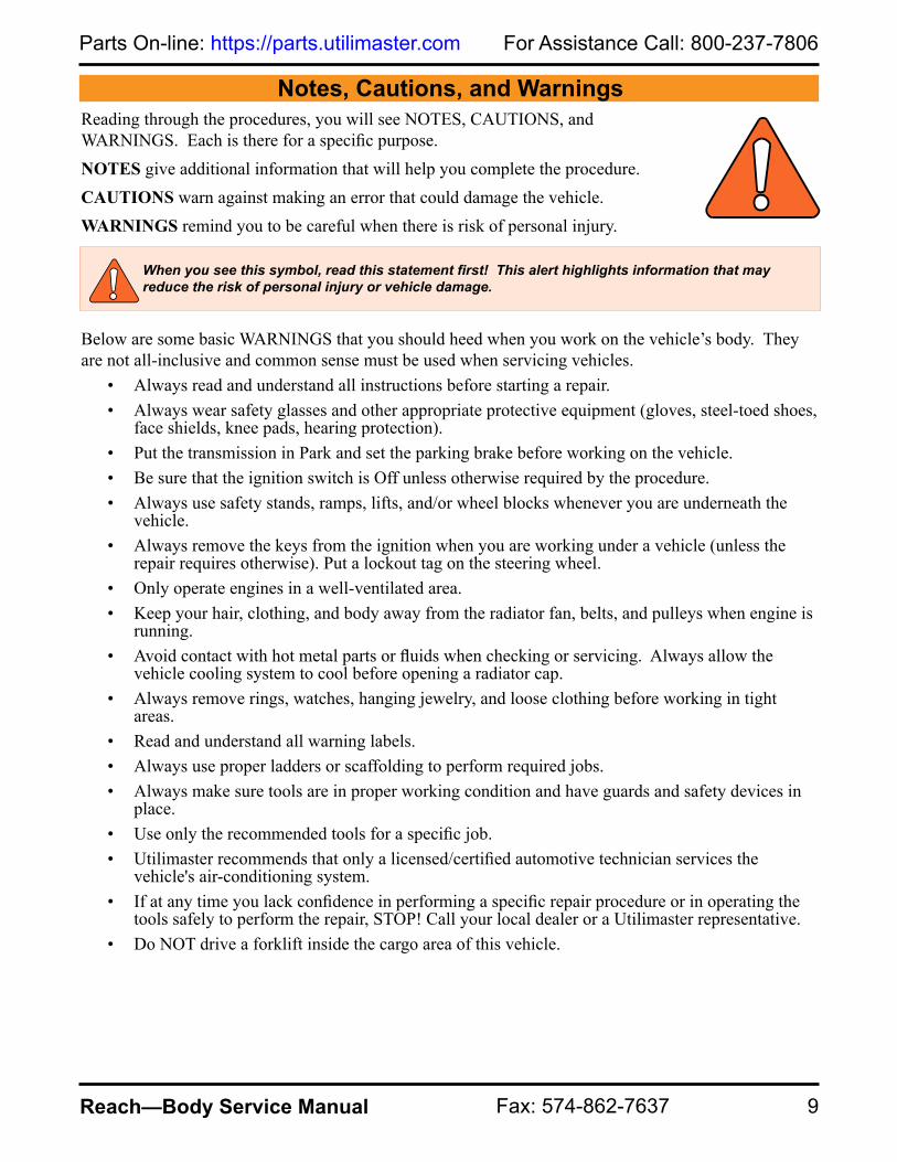
When you see this symbol, read this statement first! This alert highlights information that may reduce the risk of personal injury or vehicle damage.
Notes, Cautions, and WarningsReading through the procedures, you will see NOTES, CAUTIONS, and WARNINGS. Each is there for a specific purpose. NOTES give additional information that will help you complete the procedure.CAUTIONS warn against making an error that could damage the vehicle.WARNINGS remind you to be careful when there is risk of personal injury.
Below are some basic WARNINGS that you should heed when you work on the vehicle’s body. They are not all-inclusive and common sense must be used when servicing vehicles.
• Always read and understand all instructions before starting a repair.• Always wear safety glasses and other appropriate protective equipment (gloves, steel-toed shoes,
face shields, knee pads, hearing protection).• Put the transmission in Park and set the parking brake before working on the vehicle.• Be sure that the ignition switch is Off unless otherwise required by the procedure.• Always use safety stands, ramps, lifts, and/or wheel blocks whenever you are underneath the
vehicle.• Always remove the keys from the ignition when you are working under a vehicle (unless the
repair requires otherwise). Put a lockout tag on the steering wheel.• Only operate engines in a well-ventilated area.• Keep your hair, clothing, and body away from the radiator fan, belts, and pulleys when engine is
running.• Avoid contact with hot metal parts or fluids when checking or servicing. Always allow the
vehicle cooling system to cool before opening a radiator cap.• Always remove rings, watches, hanging jewelry, and loose clothing before working in tight
areas.• Read and understand all warning labels.• Always use proper ladders or scaffolding to perform required jobs. • Always make sure tools are in proper working condition and have guards and safety devices in
place. • Use only the recommended tools for a specific job.• Utilimaster recommends that only a licensed/certified automotive technician services the
vehicle's air-conditioning system.• If at any time you lack confidence in performing a specific repair procedure or in operating the
tools safely to perform the repair, STOP! Call your local dealer or a Utilimaster representative. • Do NOT drive a forklift inside the cargo area of this vehicle.
For Assistance Call: 800-237-7806 Visit us at: www.utilimaster.com
10 Reach—Body Service Manual E-mail: [email protected]
�������������
���
����������
���
�����
����
���
���������
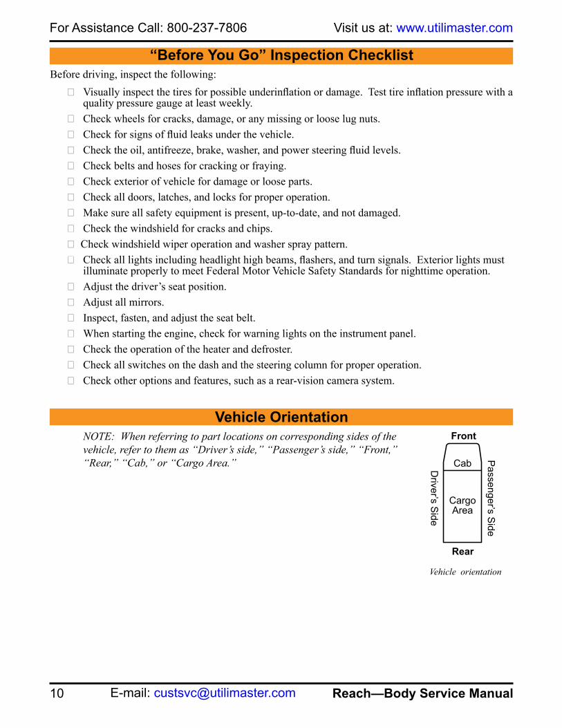
Vehicle orientation
“Before You Go” Inspection ChecklistBefore driving, inspect the following:
❑ Visually inspect the tires for possible underinflation or damage. Test tire inflation pressure with a quality pressure gauge at least weekly.
❑ Check wheels for cracks, damage, or any missing or loose lug nuts.❑ Check for signs of fluid leaks under the vehicle.❑ Check the oil, antifreeze, brake, washer, and power steering fluid levels.❑ Check belts and hoses for cracking or fraying.❑ Check exterior of vehicle for damage or loose parts.❑ Check all doors, latches, and locks for proper operation.❑ Make sure all safety equipment is present, up-to-date, and not damaged.❑ Check the windshield for cracks and chips. ❑ Check windshield wiper operation and washer spray pattern.❑ Check all lights including headlight high beams, flashers, and turn signals. Exterior lights must
illuminate properly to meet Federal Motor Vehicle Safety Standards for nighttime operation.❑ Adjust the driver’s seat position.❑ Adjust all mirrors. ❑ Inspect, fasten, and adjust the seat belt. ❑ When starting the engine, check for warning lights on the instrument panel. ❑ Check the operation of the heater and defroster. ❑ Check all switches on the dash and the steering column for proper operation.❑ Check other options and features, such as a rear-vision camera system.
Vehicle OrientationNOTE: When referring to part locations on corresponding sides of the vehicle, refer to them as “Driver’s side,” “Passenger’s side,” “Front,” “Rear,” “Cab,” or “Cargo Area.”

DEF Fill Door Diesel Fuel FillReflector
Reflector
SideMarkerLight
Cab Sliding Door
Sidewall Rub Rail
Driver's side profile
Side MarkerLights
One-PieceRoof
Vehicle overview
Front profile
Mirror
Turn andParkingLights
Identification Lights
One-PieceRoof
Hood
Windshield
Headlightand
Parking LightBumperFascia
Wipers
ClearanceLights
Rear profile
BackupLights
Reflector
Stop andTail
Lamps
RearTwin
Doors
TurnLamps
Side Dock
Bumper
Release Handle
Rear Shock Step BumperLicense
PlateLight
Identification Lights Clearance
Lights
11
For Assistance Call: 800-237-7806Parts On-line: https://parts.utilimaster.com
Reach—Body Service Manual Fax: 574-862-7637
Vehicle Overview

Figure LA–15Federal Certification Label
For Assistance Call: 800-237-7806 Visit us at: www.utilimaster.com
12 Reach—Body Service Manual E-mail: [email protected]
VIN, Body Serial, and Work Order Numbers
The 15-digit Utilimaster Body (or Unit) Serial Number is recorded on the Federal Certification Label. This label is a plastic decal (about 11" long and 2" high) that contains a variety of manufacturing information (including the VIN and Work Order Number). This label can be found attached to the door post behind the driver’s seat.The 17-digit chassis Vehicle Identification Number (VIN) is the legal identifier for this vehicle and is the number recorded in the license plate registration. The VIN is recorded on the Federal Certification Label.The Body Serial Number or 7-digit Work Order Number can be used to identify the body for service inquiries or if the body is no longer mounted on the original chassis.

13
For Assistance Call: 800-237-7806Parts On-line: https://parts.utilimaster.com
Reach—Body Service Manual Fax: 574-862-7637
Service ProceduresBatteries
AccessNOTE: The access panel for the batteries is located in the driver’s side step well.
Disconnect1. Make sure ignition switch is Off.
2. Disconnect the Negative (BLACK) battery cable(s) first.
3. Tuck the battery cable away from the terminal to prevent accidental contact.
WARNING: Always remove the (BLACK) Negative cable first and connect it last.
CAUTION: Note the location of the battery and the cable routing and reinstall in exactly the same way. When reattaching the Positive (RED) cables, the doubling of the two cables must be in the same positions as before.
WARNING: Batteries that are improperly connected, jumped, or charged can potentially explode and discharge acid, causing vehicle damage and personal injury. Carefully follow the chassis manufacturer’s recommendations for those procedures.
WARNING: Always wear proper protective equipment when working around batteries.
WARNING: Battery posts and related accessories may contain lead and lead compounds. Wash hands after handling.
Battery access panel in driver’s step well

For Assistance Call: 800-237-7806 Visit us at: www.utilimaster.com
14 Reach—Body Service Manual E-mail: [email protected]
Body Panel Repair
OverviewThis section summarizes the various repair options for the composite body panels (hood, sidewalls, and roof) on the Reach vehicle. They are listed in order of severity of damage and difficulty of repair.
Gelcoat Repair: The exterior body of the Reach has a gelcoat finish. Unlike painted surfaces, superficial damage to the gelcoat can often be buffed out to its original finish. Dents and deep scratches can be covered by applying a layer of gelcoat that is sanded and buffed back to its finished look. Adding the color of the original body to the gelcoat before application eliminates need for paint.
Minor Repair: Damage that penetrates the composite (glass-reinforced) substructure but does NOT go through to the other side OR a hole no larger than a golf ball can be repaired with a commonly obtained resin and fiberglass matting kit.
Major Repair: A hole or damaged area larger than a golf ball should be cut out and a replacement plug of new material should be bonded in its place.
Extreme Repair: Damage that impacts multiple areas (roof, side wall, rear structure) that requires replacing structural aluminum extrusions should be evaluated by an experienced technician familiar with the Reach design before attempting the repair.
Gelcoat Repair
Use the gelcoat repair process for dents and scratches that do NOT penetrate the composite substructure.1. Use a marker to highlight all cracks.
2. Remove any decals or body graphics in the repair area.
3. Use a die grinder with a rotary file bit to open and roughen the edges and remove any loose debris.
4. Sand 1–2" beyond the perimeter of the repair area.
CAUTION: Utilimaster recommends that body panel repairs be done by an experienced body shop or at Utilimaster's Customer Service Department in Wakarusa, Indiana. Contact Utilimaster Customer Service Department for further assistance.
CAUTION: Read and understand ALL product instructions and safety procedures. The effectiveness of the repair can be compromised by environmental conditions and poor application. Product application and safety instructions provided by the manufacturers always supersede information provided by Utilimaster.
WARNING: Use the proper protective equipment (rubber gloves, mask, etc.) appropriate to the process.
Mark cracks Using a die grinder to clean out gelcoat

15
For Assistance Call: 800-237-7806Parts On-line: https://parts.utilimaster.com
Reach—Body Service Manual Fax: 574-862-7637
5. Inspect the damage for cracks in substructure. If there is damage to the substructure, proceed to the Minor Repair section.
6. Mask off or cover areas to avoid overspray.
7. Thoroughly clean the area with alcohol or acetone.
8. Mix gelcoat and hardener in container and thin with acetone to make a mixture that can be applied with a sprayer. Tint to OEM color.
9. Spray a thick layer of gelcoat over the repair area, feathering out toward edges.
10. Allow gelcoat to dry.
11. Thoroughly clean area with acetone.
12. Sand with 120 grit sandpaper until flush with surface.
13. Check for low spots and holes. Apply more gelcoat feathering out toward the edges and sand with 120 grit sandpaper. Repeat as necessary.
14. Allow to dry.
15. Sand with 120–240 grit wet sandpaper.
16. Use a buffer and rubbing compound to smooth the surface.
17. Use a buffer with wax or polishing or glazing compound to blend the area.
Spraying on gelcoat
Buffing the gelcoat

For Assistance Call: 800-237-7806 Visit us at: www.utilimaster.com
16 Reach—Body Service Manual E-mail: [email protected]
Minor Composite Repair
Minor repair is necessary with damage that penetrates the composite (glass-reinforced) substructure that does NOT go through to the other side OR holes no larger than a golf ball.
1. Remove any decals or body graphics in the repair area.
2. Use a grinder to remove the damaged material.
NOTE: For cracks, drill a hole slightly larger than the crack width to prevent the crack from growing.
3. Sand with 80–120 grit sandpaper.
4. Thoroughly clean area with alcohol or acetone.
5. Mask off or cover areas to avoid dripping resin.
6. Repair area with resin and fiberglass matting.
7. Allow the resin to dry.
8. Add more resin and matting as necessary and repeat sanding.
9. Sand with 120–240 wet sandpaper.
10. Repair gelcoat.
See Repair Gelcoat.
Grind damaged section.
Resin and fiberglass matting
CAUTION: Utilimaster recommends that body panel repairs be done by an experienced body shop or at Utilimaster's Customer Service Department in Wakarusa Indiana. Contact Utilimaster Customer Service Department for further assistance.
CAUTION: Read and understand ALL product instructions and safety procedures. The effectiveness of the repair can be compromised by environmental conditions and poor application. Product application and safety instructions provided by the manufacturers always supersedes information provided by Utilimaster.
WARNING: Use the proper protective equipment (rubber gloves, mask, etc.) appropriate to the process.

17
For Assistance Call: 800-237-7806Parts On-line: https://parts.utilimaster.com
Reach—Body Service Manual Fax: 574-862-7637
Major Composite Repair
Major repair is necessary when damage to the composite (glass-reinforced) substructure is larger than a golf ball.
1. Remove any decals or body graphics in the repair area.
2. Remove anything mounted inside the vehicle that would be affected by the repair process.
3. Measure the damaged area and use a straight edge and square to cut out a replacement plug from a new panel. The plug should be at least 1" larger than the damaged area on all sides.
4. Place the plug over the area to be removed and trace the perimeter.
5. Use a saw or die grinder to cut out the damaged area.
6. Use a rotary file or grinder to smooth the edges of the hole.
7. Sand with 80–120 grit sandpaper.
8. Bevel all the edges of the hole and the plug.
9. Use 120 grit sandpaper to sand 1–2" past the edges of the opening and plug.
10. Test fit plug and modify as necessary.
11. Carefully center plug in the opening and secure with clamps or fasteners.
NOTE: The plug can be held in place with wood blocks and screws that can be removed after the first resin application.
12. Remove plug and set aside.
13. Mask off or cover areas to avoid dripping resin.
CAUTION: Utilimaster recommends that body panel repairs be done by an experienced body shop or at Utilimaster's Customer Service Department in Wakarusa, Indiana. Contact Utilimaster Customer Service Department for further assistance.
CAUTION: Read and understand ALL product instructions and safety procedures. The effectiveness of the repair can be compromised by environmental conditions and poor application. Product application and safety instructions provided by the manufacturers always supersedes information provided by Utilimaster.
WARNING: Use the proper protective equipment (rubber gloves, mask, etc.) appropriate to the process.
CAUTION: Do NOT get resin on the clamps or mounting fixtures.
Cut out damaged area

For Assistance Call: 800-237-7806 Visit us at: www.utilimaster.com
18 Reach—Body Service Manual E-mail: [email protected]
14. Thoroughly clean the repair area with alcohol or acetone.
15. Coat all four sides of the plug and the hole with resin, place in the opening, and secure with clamps.
16. Carefully center the plug in the opening and secure with clamps or fasteners.
17. Bond the perimeter of the plug to the body with resin and fiberglass matting.
18. Allow resin to dry.
19. Remove temporary support and apply resin to any low spots and holes.
20. Sand with 80–120 grit sandpaper.
21. Add more resin and matting and repeat sanding until surfaces are smooth.
22. Sand with 120–240 wet sandpaper.
23. Repair gelcoat.
See Repair Gelcoat.
CAUTION: The replacement plug needs to be mounted flat and flush with the body surface.
Bond plug in place with resin and matting.

19
For Assistance Call: 800-237-7806Parts On-line: https://parts.utilimaster.com
Reach—Body Service Manual Fax: 574-862-7637
Bumpers Front Fascia Removal
1. Open hood.
See Open Hood.2. Remove grille.
See Remove Grille.3. Remove two M6 screws in headlight bezel.
4. Remove two M4 screws in headlight bezel and set bezel aside.
5. Remove two M6 screws in top center of fascia.
6. Remove four M6 screws from underside of fascia.
7. Unplug turn lights.
8. Remove two M6 nuts and bolts from the bracket under headlight.
Turn light Bracket under headlight
Screw locations on top of fascia
Screw locations on underside of fascia
CAUTION: Discard ALL used fasteners and replace with new. If using a fastener that does NOT have preapplied thread lock, apply a medium-grade liquid thread lock.

For Assistance Call: 800-237-7806 Visit us at: www.utilimaster.com
20 Reach—Body Service Manual E-mail: [email protected]
9. Remove two M6 nuts from steel bumper bracket.
10. Repeat on opposite side.
11. Set bumper fascia aside.
Installation
1. Secure steel bumper brackets to M6 bolts that are attached to the fascia.
2. Plug in turn lights.
3. Secure fascia bracket under headlight with two M6 bolts and nuts.
Steel bumper brackets
Turn light Bracket under headlight
CAUTION: Discard ALL used fasteners and replace with new. If using a fastener that does NOT have preapplied thread lock, apply a medium-grade liquid thread lock.

21
For Assistance Call: 800-237-7806Parts On-line: https://parts.utilimaster.com
Reach—Body Service Manual Fax: 574-862-7637
4. Secure underside of fascia with four M6 screws.
5. Torque to 7–8 ft•lbs.
6. Secure top of fascia with two M6 screws.
7. Torque to 7–8 ft•lbs.
8. Secure headlight bezel with two M6 screws.
9. Torque to 7–8 ft•lbs.
10. Secure headlight bezel with two M4 screws.
11. Install grille.
See Install Grille.12. Secure prop rod into rest position and close hood.
Screw locations on top of fascia
Screw locations on underside of fascia

For Assistance Call: 800-237-7806 Visit us at: www.utilimaster.com
22 Reach—Body Service Manual E-mail: [email protected]
Rear BumperShock AbsorbersRemoval
1. Remove eight M12 hex-head bolts and nuts from shock absorbers.
2. Set step bumper aside.
3. Remove hex-head bolts and nuts in frame extension(s) and remove shock absorber(s).
WARNING: Always support the bumper to keep it from falling.
1
3
3
1
2
CAUTION: Discard ALL used fasteners and replace with new. If using a fastener that does NOT have preapplied thread lock, apply a medium-grade liquid thread lock.

23
For Assistance Call: 800-237-7806Parts On-line: https://parts.utilimaster.com
Reach—Body Service Manual Fax: 574-862-7637
Installation
1. Secure shock absorber(s) to frame extension(s) with M12 hex-head bolts and nuts.
2. Torque nuts to 60–71 ft•lbs.
3. Secure rear step bumper to each shock absorber(s) with four M12 hex-head bolts and nuts.
4. Torque nuts to 60–71 ft•lbs.
See Bumper Maintenance.
4
1
2
3
WARNING: Always support the bumper to keep it from falling.
CAUTION: Discard ALL used fasteners and replace with new. If using a fastener that does NOT have preapplied thread lock, apply a medium-grade liquid thread lock.

For Assistance Call: 800-237-7806 Visit us at: www.utilimaster.com
24 Reach—Body Service Manual E-mail: [email protected]
D-BumperRemoval
1. Remove M6 bolts and nuts from D-bumper through access holes.
2. Set D-bumper and retainer plate aside.
Installation
1. Insert retainer plate into D-bumper.
2. Secure D-bumper with M6 bolts and nuts.
3. Torque nuts to 7–8 ft•lbs.
RUBBER D-BUMPER
NUT M6-1.00 FLG
RETAINER PLATE
BOLT M6-1.00 X 30MM LG HEX
CAUTION: Discard ALL used fasteners and replace with new. If using a fastener that does NOT have preapplied thread lock, apply a medium-grade liquid thread lock.

25
For Assistance Call: 800-237-7806Parts On-line: https://parts.utilimaster.com
Reach—Body Service Manual Fax: 574-862-7637
Side Dock BumpersRemoval
1. Remove lower post cladding.
See Remove Lower Post Cladding.2. Remove M6 hex-head screws from top and bottom brackets.
3. Remove #8 x 5/8" screws from brackets.
4. Set dock bumper aside.
Installation
1. Secure brackets to side dock bumpers with #8 x 5/8" screws.
2. Secure M6 hex-head screws in top and bottom brackets.
3. Install lower post cladding.
See Install Lower Post Cladding.
SCREW M6-1.0 x 16 HX FLG
SCREW #8 x 5/8
LOWER DOCK BUMPER BRKT
DOCK BUMPER
UPPER DOCK BUMPER BRKT
CAUTION: Discard ALL used fasteners and replace with new. If using a fastener that does NOT have preapplied thread lock, apply a medium-grade liquid thread lock.

For Assistance Call: 800-237-7806 Visit us at: www.utilimaster.com
26 Reach—Body Service Manual E-mail: [email protected]
CladdingFront FenderRemoval
1. Remove three screws in wheel liner.
2. Remove M6 nut from stud that is attached to the fender. The nut is located inside the engine compartment.
3. Remove two M6 nuts from studs that are attached to fender. These nuts are located above the wheel liner.
4. Remove two M6 screws from cladding at front door post.
5. Lift cladding out of channel and set aside.
Installation
1. Set cladding onto channel.
2. Secure cladding at front door post with two M6 screws.
3. Secure cladding above wheel liner with two M6 nuts.
4. Secure cladding inside engine compartment with one M6 nut.
5. Torque to 7–8 ft•lbs.
6. Secure wheel liner with three screws.
CAUTION: Discard ALL used fasteners and replace with new. If using a fastener that does NOT have preapplied thread lock, apply a medium-grade liquid thread lock.
Nut location inside engine compartment
Screw locations in doorwayNut locations above wheel liner
Screw locations in wheel liner

27
For Assistance Call: 800-237-7806Parts On-line: https://parts.utilimaster.com
Reach—Body Service Manual Fax: 574-862-7637
RearThere are five pieces to the rear cladding; two lower pieces on either side of the door around the dock bumpers, two upper pieces on either side of the door above the lower pieces, and the header above the door. Each process describes the removal and installation of only one piece. Repeat the process on the opposite side if necessary.
Lower Post Removal
NOTE: The dock bumpers do NOT need to be removed to replace the lower post cladding. NOTE: If not removing header, remove bottom two M6 screws in upper post cladding.
1. Remove five M6 screws in lower post cladding.
2. Slide lower post cladding from underneath upper post cladding and set aside.
Lower Post Installation
1. Secure lower post cladding with five M6 screws.
2. Torque to 7–8 ft•lbs.
Upper post cladding screw
Lower post cladding
CAUTION: Discard ALL used fasteners and replace with new. If using a fastener that does NOT have preapplied thread lock, apply a medium-grade liquid thread lock.

For Assistance Call: 800-237-7806 Visit us at: www.utilimaster.com
28 Reach—Body Service Manual E-mail: [email protected]
Upper Post RemovalThis process describes the removal and installation of the header and one side of the upper post cladding. Repeat the process on the opposite side if necessary.
1. Remove six M6 screws from bottom of header.
2. Remove 12 Allen head screws from top of header.
3. Remove header and lay on top of roof.
4. Disconnect wires to clearance lights.
5. Disconnect camera cable.
6. Remove seven M6 screws in upper post cladding and set aside.
Upper Post Installation
1. Secure upper post cladding with seven M6 screws.
2. Torque to 7–8 ft•lbs.
3. Set header on roof.
4. Connect cable to camera.
5. Connect wires to clearance lights.
6. Secure bottom of header with six M6 screws.
7. Torque to 7–8 ft•lbs.
8. Secure top of header with 12 Allen head screws.
CAUTION: Discard ALL used fasteners and replace with new. If using a fastener that does NOT have preapplied thread lock, apply a medium-grade liquid thread lock.
Header cladding
Upper post cladding

29
For Assistance Call: 800-237-7806Parts On-line: https://parts.utilimaster.com
Reach—Body Service Manual Fax: 574-862-7637
Kickplate Removal
1. Remove lower post cladding
See Remove Lower Post Cladding.2. Unplug taillights.
3. Remove 12 rivets from the rear threshold and set threshold aside.
See Remove Blind Rivet.4. Remove seven rivets from the bottom lip of the kickplate
cladding.
See Remove Blind Rivet.5. Remove two M6 screws at the top corners of the kickplate
cladding.
6. Set kickplate cladding aside.
Kickplate Installation
1. Secure kickplate cladding at the top corners with M6 screws.
2. Torque to 7–8 ft•lbs.
3. Secure kickplate cladding at the bottom lip with seven rivets.
See Install Blind Rivet.4. Secure rear threshold with 12 rivets.
See Install Blind Rivet.5. Plug in taillights.
6. Install lower post cladding.
See Install Lower Post Cladding.
CAUTION: Discard ALL used fasteners and replace with new. If using a fastener that does NOT have preapplied thread lock, apply a medium-grade liquid thread lock.
Screw location on kickplate cladding
Rivet location

For Assistance Call: 800-237-7806 Visit us at: www.utilimaster.com
30 Reach—Body Service Manual E-mail: [email protected]
Sidewall Removal
NOTE: The rear fender cladding must be removed prior to removing the sidewall cladding.1. Remove M6 bolts at the U-nuts from braces located underneath the vehicle.
2. Remove M6 screws from cladding.
3. Lift cladding out of channel and set aside.
Cladding channel
CAUTION: Discard ALL used fasteners and replace with new. If using a fastener that does NOT have preapplied thread lock, apply a medium-grade liquid thread lock.
Bolt and U-nut on cladding brace
Sidewall cladding

31
For Assistance Call: 800-237-7806Parts On-line: https://parts.utilimaster.com
Reach—Body Service Manual Fax: 574-862-7637
Installation
1. Set cladding onto channel.
2. Secure cladding with M6 screws.
3. Torque to 7–8 ft•lbs.
4. Secure braces to cladding with M6 bolts.
5. Torque to 7–8 ft•lbs.
Cladding channel
CAUTION: Discard ALL used fasteners and replace with new. If using a fastener that does NOT have preapplied thread lock, apply a medium-grade liquid thread lock.
Sidewall cladding
Bolt and U-nut on cladding brace

For Assistance Call: 800-237-7806 Visit us at: www.utilimaster.com
32 Reach—Body Service Manual E-mail: [email protected]
Dash Panels
LOUVER
A-PILLARPANEL
BRAKE PANEL
CLUSTER PANEL
LOWER IP PANEL
WASHER BOTTLE PANEL
DASH VALANCE PANEL
BRAKE FLUIDPANEL
HOOD CLUSTER
FUSE COVER PANEL
TRAY PANEL
IGNITION PANELCONVENIENCEPANEL A-PILLAR
PANEL

33
For Assistance Call: 800-237-7806Parts On-line: https://parts.utilimaster.com
Reach—Body Service Manual Fax: 574-862-7637
A-Pillar Removal
NOTE: On driver’s side, remove four M6 screws from A-pillar grab handle prior to removing A-pillar.
See Remove A-Pillar Grab Handle.1. Remove seven M6 scrivets from A-pillar.
See Remove Scrivet.2. Set A-pillar aside.
Installation
1. Secure A-pillar with seven M6 scrivets.
See Install Scrivet.NOTE: On driver’s side, secure grab handle to A-pillar with four M6 screws and torque to 7–8 ft •lbs.
See Remove A-Pillar Grab Handle.
Brake Panel
Removal
1. Remove three #8 Phillips head screws from brake panel.
2. Remove brake panel and set aside.
Installation
1. Secure brake panel to dash with three #8 Phillips head screws.
2. Torque to 23–27 in•lbs.
CAUTION: Discard ALL used fasteners and replace with new. If using a fastener that does NOT have preapplied thread lock, apply a medium-grade liquid thread lock.
A-pillar
Brake panel
CAUTION: Discard ALL used fasteners and replace with new. If using a fastener that does NOT have preapplied thread lock, apply a medium-grade liquid thread lock.

For Assistance Call: 800-237-7806 Visit us at: www.utilimaster.com
34 Reach—Body Service Manual E-mail: [email protected]
Cluster Panel Removal
1. Remove hood cluster panel.
See Remove Hood Cluster Panel.2. Remove four M6 screws from cluster
panel and set panel aside.
Installation
1. Secure cluster panel to dash with four M6 screws.
2. Torque to 7–8 ft•lbs.
3. Install hood cluster panel.
See Install Hood Cluster Panel.
Dash Valance Panel Removal
1. Remove A-pillars.
See Remove A-Pillars.2. Remove handrail and washer bottle cover.
See Remove Handrail.3. Remove eight #8 Phillips head screw from lower IP panel.
CAUTION: Discard ALL used fasteners and replace with new. If using a fastener that does NOT have preapplied thread lock, apply a medium-grade liquid thread lock.
Cluster panel
CAUTION: Discard ALL used fasteners and replace with new. If using a fastener that does NOT have preapplied thread lock, apply a medium-grade liquid thread lock.
Dash valance panel

35
For Assistance Call: 800-237-7806Parts On-line: https://parts.utilimaster.com
Reach—Body Service Manual Fax: 574-862-7637
4. Remove brake fluid panel from dash by releasing swell latches.
See Release Swell Latches.5. Remove brake panel.
See Remove Brake Panel.6. Remove hood cluster panel.
See Remove Hood Cluster Panel.7. Remove cluster panel.
See Remove Cluster Panel.8. Remove tray panel.
See Remove Tray Panel.9. Remove dash vent by lifting with a flat blade screwdriver and
pulling spring clip out to one side.
10. Remove radio.
See Remove Stereo.11. Disconnect wiring harness to heater controls.
12. Disconnect wiring harness to switches.
13. Disconnect wiring harness to 12V outlet.
14. Remove air louver by holding the front of the louver and turning the back counterclockwise.
15. Remove four #8 Phillips head screws from the convenience panel.
16. Remove M6 screw and nut from center of dash valance panel.
17. Remove eleven M6 screws from the panel.
18. Remove panel and set aside.
Dash valance panel
Screw locations
Dash vent
Air louver

For Assistance Call: 800-237-7806 Visit us at: www.utilimaster.com
36 Reach—Body Service Manual E-mail: [email protected]
Installation
1. Secure panel with M6 nut and screw in the center of dash valance panel.
2. Secure panel with eleven M6 screws.
3. Torque to 15–25 in•lbs.
4. Secure convenience panel to dash with four #8 Phillips head screws.
5. Torque to 23–27 in•lbs.
6. Secure air louver by holding the front of the louver and turning the back clockwise.
7. Connect wiring harness to switches.
8. Connect wiring harness to heater controls.
9. Connect wiring harness to 12V outlet.
10. Install radio.
See Install Stereo.11. Secure dash vent by pushing in spring clip with a flat blade
screwdriver.
12. Install tray panel.
See Install Tray Panel.13. Install cluster panel.
See Install Cluster Panel.
CAUTION: Discard ALL used fasteners and replace with new. If using a fastener that does NOT have preapplied thread lock, apply a medium-grade liquid thread lock.
Screw locations
Dash vent
Air louver

37
For Assistance Call: 800-237-7806Parts On-line: https://parts.utilimaster.com
Reach—Body Service Manual Fax: 574-862-7637
14. Install hood cluster panel.
See Install Hood Cluster Panel.15. Install brake panel.
See Install Brake Panel.16. Secure brake fluid panel with two swell latches.
See Secure Swell Latches.17. Secure lower IP panel with eight #8 Phillips head screws.
18. Torque to 23–27 in•lbs.
19. Install handrail and washer bottle panel.
See Install Handrail.20. Install A-pillars.
See Install A-Pillars.
Fuse Access The fuse panels are mounted below the convenience panel behind the dash fascia. The fuse panel on the left is for the Utilimaster body features, and the panel on the right is for the chassis functions.
Dash valance panel
Utilimaster body fuse locations Fuse panels
For Assistance Call: 800-237-7806 Visit us at: www.utilimaster.com
38 Reach—Body Service Manual E-mail: [email protected]
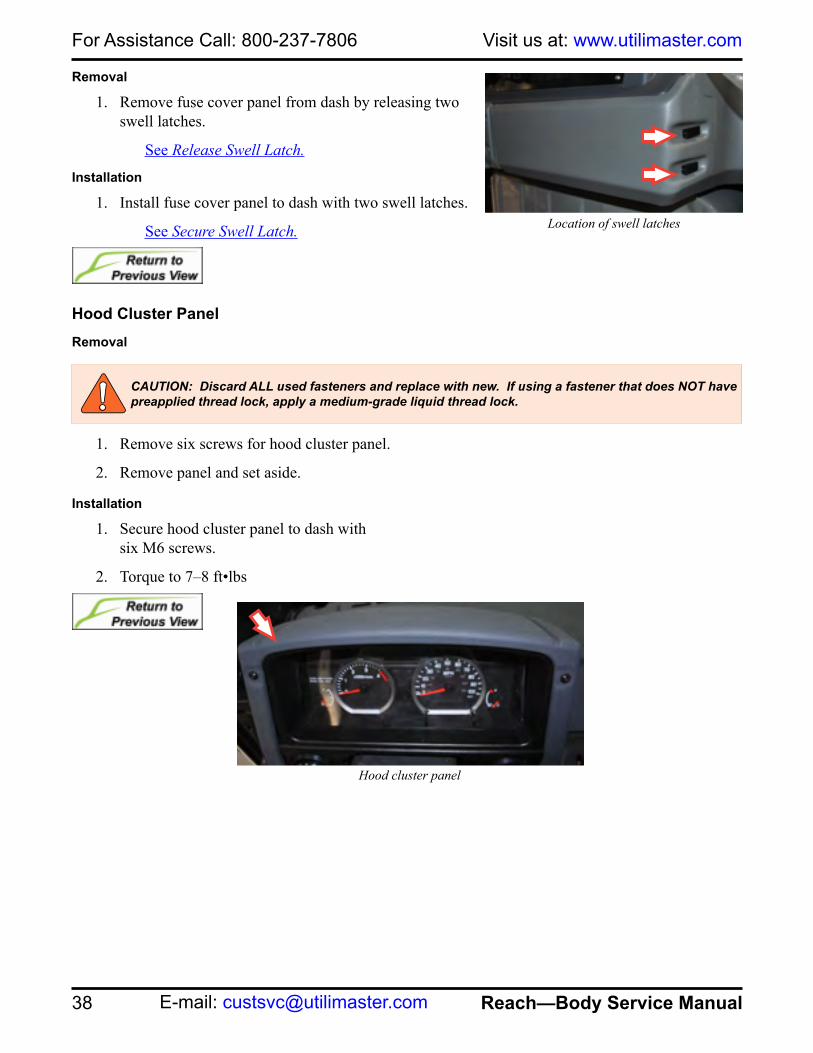
Removal
1. Remove fuse cover panel from dash by releasing two swell latches.
See Release Swell Latch.
Installation
1. Install fuse cover panel to dash with two swell latches.
See Secure Swell Latch.
Hood Cluster Panel Removal
1. Remove six screws for hood cluster panel.
2. Remove panel and set aside.
Installation
1. Secure hood cluster panel to dash with six M6 screws.
2. Torque to 7–8 ft•lbs
Location of swell latches
Hood cluster panel
CAUTION: Discard ALL used fasteners and replace with new. If using a fastener that does NOT have preapplied thread lock, apply a medium-grade liquid thread lock.
39
For Assistance Call: 800-237-7806Parts On-line: https://parts.utilimaster.com
Reach—Body Service Manual Fax: 574-862-7637
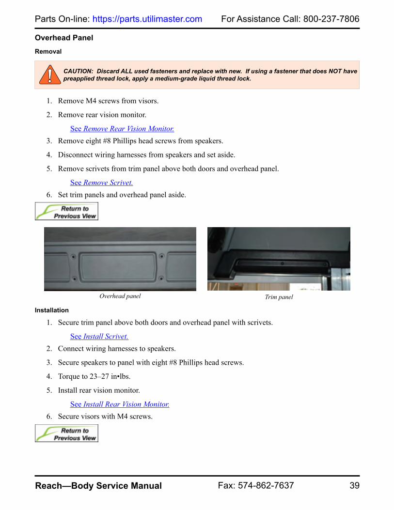
Overhead Panel Removal
1. Remove M4 screws from visors.
2. Remove rear vision monitor.
See Remove Rear Vision Monitor.3. Remove eight #8 Phillips head screws from speakers.
4. Disconnect wiring harnesses from speakers and set aside.
5. Remove scrivets from trim panel above both doors and overhead panel.
See Remove Scrivet.6. Set trim panels and overhead panel aside.
Installation
1. Secure trim panel above both doors and overhead panel with scrivets.
See Install Scrivet.2. Connect wiring harnesses to speakers.
3. Secure speakers to panel with eight #8 Phillips head screws.
4. Torque to 23–27 in•lbs.
5. Install rear vision monitor.
See Install Rear Vision Monitor.6. Secure visors with M4 screws.
CAUTION: Discard ALL used fasteners and replace with new. If using a fastener that does NOT have preapplied thread lock, apply a medium-grade liquid thread lock.
Trim panelOverhead panel

For Assistance Call: 800-237-7806 Visit us at: www.utilimaster.com
40 Reach—Body Service Manual E-mail: [email protected]
Tray Panel Removal
1. Remove four M6 screws from tray panel.
2. Remove panel and set aside.
Installation
1. Secure tray panel to dash with four M6 screws.
2. Torque to 7–8 ft•lbs.
Washer Bottle Panel Removal
1. Remove fire extinguisher.
See Remove Fire Extinguisher.2. Remove fuse cover panel.
See Remove Fuse Cover Panel.3. Remove five #8 Phillips head screws and washers
from washer panel.
4. Remove one M6 screw from panel.
5. Remove panel and set aside.
Installation
1. Secure washer panel to dash with one M6 screw.
2. Torque to 7–8 ft•lbs.
3. Secure panel to dash with five washers #8 Phillips head screws.
4. Torque to 23–27 in•lbs.
5. Install fuse cover panel.
See Install Fuse Cover Panel.6. Install fire extinguisher.
See Install Fire Extinguisher.
CAUTION: Discard ALL used fasteners and replace with new. If using a fastener that does NOT have preapplied thread lock, apply a medium-grade liquid thread lock.
Tray panel
Washer bottle panel
CAUTION: Discard ALL used fasteners and replace with new. If using a fastener that does NOT have preapplied thread lock, apply a medium-grade liquid thread lock.

41
For Assistance Call: 800-237-7806Parts On-line: https://parts.utilimaster.com
Reach—Body Service Manual Fax: 574-862-7637
Door Ajar SwitchDoor ajar switches can be located at any of the doors. This type of switch indicates when a door is open.
Removal
NOTE: Keep all hardware for reinstallation. 1. Use a Phillips head screwdriver to loosen the two screws to
remove wires.
2. Use a Phillips head screwdriver to remove the two screws and lock nuts from switch.
3. Remove switch from mounting bracket and set aside.
Installation
1. Use a Phillips head screwdriver to secure switch onto mounting bracket with two screws and two lock nuts.
2. Place wires on screws and tighten with a Phillips head screwdriver.
Door ajar switch

For Assistance Call: 800-237-7806 Visit us at: www.utilimaster.com
42 Reach—Body Service Manual E-mail: [email protected]
Doors, BulkheadAdjustment
1. Loosen lower door track fasteners and rotate guides counterclockwise to increase tension.
2. Cycle door to test resistance.
3. Torque to 7–8 ft•lbs.
Door track guides
CAUTION: Discard ALL used fasteners and replace with new. If using a fastener that does NOT have preapplied thread lock, apply a medium-grade liquid thread lock.
43
For Assistance Call: 800-237-7806Parts On-line: https://parts.utilimaster.com
Reach—Body Service Manual Fax: 574-862-7637
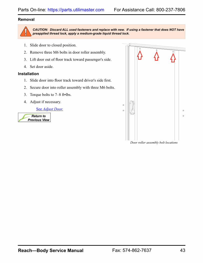
Removal
1. Slide door to closed position.
2. Remove three M6 bolts in door roller assembly.
3. Lift door out of floor track toward passenger's side.
4. Set door aside.
Installation1. Slide door into floor track toward driver's side first.
2. Secure door into roller assembly with three M6 bolts.
3. Torque bolts to 7–8 ft•lbs.
4. Adjust if necessary.
See Adjust Door.
Door roller assembly bolt locations
CAUTION: Discard ALL used fasteners and replace with new. If using a fastener that does NOT have preapplied thread lock, apply a medium-grade liquid thread lock.

For Assistance Call: 800-237-7806 Visit us at: www.utilimaster.com
44 Reach—Body Service Manual E-mail: [email protected]
Catch Adjustment
1. Loosen two M6 nuts on catch.
2. Slide door into closed position.
3. Align catch with latch on door.
4. Cycle door to ensure that it seals properly and latch engages catch.
5. Adjust again if necessary.
6. Torque to 7–8 ft•lbs.
SealsRemoval
1. Open door.
2. Use a small flat blade screwdriver to lift and pull out seal from channel.
3. Discard seal.
Installation
4. Check jamb for any residual tape. Clean with isopropyl alcohol if necessary.
5. Dry fit seal to jamb and trim if necessary.
6. Remove paper backing from seal and install into jamb.
7. Cycle door open and closed to ensure seal is adhered to jamb.
Bulkhead door catch
Bulkhead door seal
CAUTION: Discard ALL used fasteners and replace with new. If using a fastener that does NOT have preapplied thread lock, apply a medium-grade liquid thread lock.
Check latch and catch alignment
Catch Plate
1/8"
Latch Tongue

45
For Assistance Call: 800-237-7806Parts On-line: https://parts.utilimaster.com
Reach—Body Service Manual Fax: 574-862-7637
Doors, Cab SliderNOTE: The cab door handle and locking options vary. Some of the most common types are described here.
To open the locked door from outside the cab, insert the key and turn clockwise 1/4 turn until lock pops out, then turn key back counter-clockwise 1/4 turn and remove the key. Push on the paddle latch towards the rear of the vehicle to slide the door open. The door will latch again in the fully open position. To open the door from inside the cab, push the top of the handle toward the rear of the vehicle. The handle unlatches the door so the door can slide toward the back of the vehicle. The door latches again in the open position.
NOTE: The door handles do NOT automatically unlock when the door is opened.To close the door from inside or outside, push the top of the handle toward the front of the vehicle and slide the door until the latch catches.To lock the doors from the inside, push the lever below the interior handle up. To unlock the door, pull down on the lever.
NOTE: When the interior lock is engaged, the key cannot open the lock from the outside.To lock the door from the outside, insert the key and turn clockwise and push in the lock button on the exterior handle.
NOTE: With this type of push-button lock, be careful NOT to leave the keys inside the vehicle and lock yourself out.
Exterior side door handle with push button lock Interior side door handle and lock
For Assistance Call: 800-237-7806 Visit us at: www.utilimaster.com
46 Reach—Body Service Manual E-mail: [email protected]
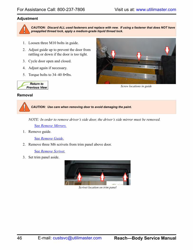
Adjustment
1. Loosen three M10 bolts in guide.
2. Adjust guide up to prevent the door from rattling or down if the door is too tight.
3. Cycle door open and closed.
4. Adjust again if necessary.
5. Torque bolts to 34–40 ft•lbs.
Removal
NOTE: In order to remove driver’s side door, the driver’s side mirror must be removed.See Remove Mirrors.
1. Remove guide.
See Remove Guide.2. Remove three M6 scrivets from trim panel above door.
See Remove Scrivet.3. Set trim panel aside.
Screw locations in guide
Scrivet location on trim panel
CAUTION: Use care when removing door to avoid damaging the paint.
CAUTION: Discard ALL used fasteners and replace with new. If using a fastener that does NOT have preapplied thread lock, apply a medium-grade liquid thread lock.

47
For Assistance Call: 800-237-7806Parts On-line: https://parts.utilimaster.com
Reach—Body Service Manual Fax: 574-862-7637
4. Remove ten M6 bolts in B-pillar.
5. Set B-pillar aside.
6. Remove three M6 bolts from roller assembly at top of door.
7. Lift door from front and pull out towards A-pillar.
8. Set door aside.
Installation
1. Install door at B-pillar first. Ensure that groove on the door is inserted between the upper V-seals.
Roller assembly screw locationsB-pillar
CAUTION: Use care when installing door to avoid damaging the paint.
Upper V-seals
CAUTION: Discard ALL used fasteners and replace with new. If using a fastener that does NOT have preapplied thread lock, apply a medium-grade liquid thread lock.

48
For Assistance Call: 800-237-7806Parts On-line: https://parts.utilimaster.com
Reach—Body Service Manual Fax: 574-862-7637
2. Secure roller assembly at top of door with three M6 bolts.
3. Torque to 7–8 ft•lbs.
4. Secure B-pillar with ten M6 bolts.
5. Torque to 7–8 ft•lbs.
6. Secure trim panel above door with three M6 scrivets.
See Install Scrivet.
7. Install guide.
See Install Guide.8. Install driver's side mirror.
See Install Mirrors.
Scrivet location on trim panel
Roller assembly screw locations
B-pillar

49
For Assistance Call: 800-237-7806Parts On-line: https://parts.utilimaster.com
Reach—Body Service Manual Fax: 574-862-7637
Catch, Front StandardAdjustment
NOTE: If driver’s side, remove brake panel.See Remove Brake Panel.
NOTE: If passenger’s side, remove washer bottle panel.See Remove Washer Bottle Panel.
1. Remove two M6 bolts on catch.
2. Close door.
3. Align catch with latch on door.
4. Cycle door to ensure that it seals properly and latch engages catch.
5. Adjust again if necessary.
6. Torque bolts to 7–8 ft•lbs.
NOTE: If driver’s side, install brake panel.See Install Brake Panel.
NOTE: If passenger’s side, install washer bottle panel.See Install Washer Bottle Panel.
Catch bolt locations
Check latch and catch alignment
Catch Plate
1/8"
Latch Tongue
CAUTION: Discard ALL used fasteners and replace with new. If using a fastener that does NOT have preapplied thread lock, apply a medium-grade liquid thread lock.

For Assistance Call: 800-237-7806 Visit us at: www.utilimaster.com
50 Reach—Body Service Manual E-mail: [email protected]
Removal
NOTE: If driver’s side, remove brake panel.See Remove Brake Panel.
NOTE: If passenger’s side, remove washer bottle panel.See Remove Washer Bottle Panel.
1. Remove two M6 bolts on catch.
2. Set catch aside.
Installation
1. Secure catch with two M6 bolts.
2. Adjust catch if necessary.
3. Torque to 7–8 ft•lbs.
NOTE: If driver’s side, install brake panel.See Install Brake Panel.
NOTE: If passenger’s side, install washer bottle panel.See Install Washer Bottle Panel.
Catch bolt locations
CAUTION: Discard ALL used fasteners and replace with new. If using a fastener that does NOT have preapplied thread lock, apply a medium-grade liquid thread lock.
Check latch and catch alignment
Catch Plate
1/8"
Latch Tongue

51
For Assistance Call: 800-237-7806Parts On-line: https://parts.utilimaster.com
Reach—Body Service Manual Fax: 574-862-7637
Catch, Front KeylessAdjustment
NOTE: If driver’s side, remove brake panel.See Remove Brake Panel.
NOTE: If passenger’s side, remove washer bottle panel.See Remove Washer Bottle Panel.
1. Remove two M6 bolts on catch.
2. Close door.
3. Align catch with latch on door.
4. Cycle door to ensure that it seals properly and latch engages catch.
5. Adjust again if necessary.
6. Torque bolts to 7–8 ft•lbs.
NOTE: If driver’s side, install brake panel.See Install Brake Panel.
NOTE: If passenger’s side, install washer bottle panel.See Install Washer Bottle Panel.
CAUTION: Discard ALL used fasteners and replace with new. If using a fastener that does NOT have preapplied thread lock, apply a medium-grade liquid thread lock.
Check latch and catch alignment
Catch Plate
1/8"
Latch Tongue
For Assistance Call: 800-237-7806 Visit us at: www.utilimaster.com
52 Reach—Body Service Manual E-mail: [email protected]
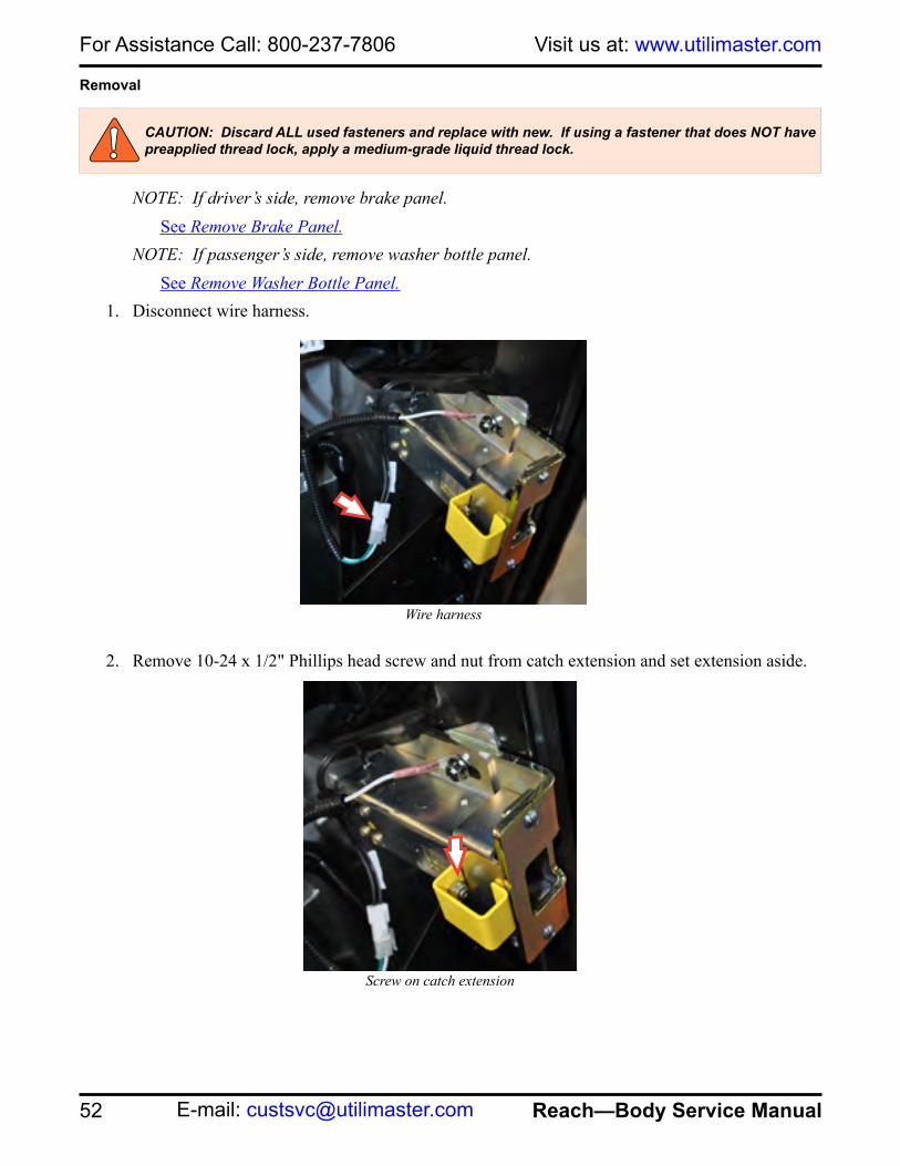
Removal
NOTE: If driver’s side, remove brake panel.See Remove Brake Panel.
NOTE: If passenger’s side, remove washer bottle panel.See Remove Washer Bottle Panel.
1. Disconnect wire harness.
2. Remove 10-24 x 1/2" Phillips head screw and nut from catch extension and set extension aside.
CAUTION: Discard ALL used fasteners and replace with new. If using a fastener that does NOT have preapplied thread lock, apply a medium-grade liquid thread lock.
Wire harness
Screw on catch extension

53
For Assistance Call: 800-237-7806Parts On-line: https://parts.utilimaster.com
Reach—Body Service Manual Fax: 574-862-7637
3. Remove two M6 bolts on catch and remove ground wire. Set catch aside.
Installation
1. Secure ground wire and catch with two M6 bolts.
Screws on catch
Screws on catch

For Assistance Call: 800-237-7806 Visit us at: www.utilimaster.com
54 Reach—Body Service Manual E-mail: [email protected]
2. Secure catch extension to catch with 10-24 x 1/2" Phillips head screw and nut.
3. Torque to 33–38 in•lbs.
4. Connect wire harness.
5. Adjust catch if necessary.
6. Torque to 7–8 ft•lbs.
NOTE: If driver’s side, install brake panel.See Install Brake Panel.
NOTE: If passenger’s side, install washer bottle panel.See Install Washer Bottle Panel.
Screw on catch extension
Wire harness

55
For Assistance Call: 800-237-7806Parts On-line: https://parts.utilimaster.com
Reach—Body Service Manual Fax: 574-862-7637
Catch, RearAdjustment
1. Loosen two M6 bolts on catch.
2. Open door.
3. Align catch with latch on door.
4. Cycle door to ensure that it seals properly and latch engages catch.
5. Adjust again if necessary.
6. Torque bolts 7–8 ft•lbs.
Removal
1. Remove two M6 bolts on catch.
2. Set catch aside.
Installation
1. Secure catch with two M6 bolts.
2. Adjust catch if necessary.
3. Torque to 7–8 ft•lbs.
Bolt locations in catch
CAUTION: Discard ALL used fasteners and replace with new. If using a fastener that does NOT have preapplied thread lock, apply a medium-grade liquid thread lock.
CAUTION: Discard ALL used fasteners and replace with new. If using a fastener that does NOT have preapplied thread lock, apply a medium-grade liquid thread lock.
Check latch and catch alignment
Catch Plate
1/8"
Latch Tongue

For Assistance Call: 800-237-7806 Visit us at: www.utilimaster.com
56 Reach—Body Service Manual E-mail: [email protected]
GuideRemoval
1. Remove sidewall cladding.
See Remove Sidewall Cladding.2. Remove five M6 screws from threshold and one M6 screw from underneath vehicle. Leave
threshold in place.
3. Remove three M10 bolts from guide.
4. Rotate threshold to remove guide.
Screw locations in guide
Threshold Screw location underneath vehicle
CAUTION: Discard ALL used fasteners and replace with new. If using a fastener that does NOT have preapplied thread lock, apply a medium-grade liquid thread lock.

57
For Assistance Call: 800-237-7806Parts On-line: https://parts.utilimaster.com
Reach—Body Service Manual Fax: 574-862-7637
Installation
1. Rotate threshold to install guide.
2. Secure guide with three M10 bolts.
3. Torque to 34–40 ft•lbs.
4. Secure threshold with five M6 screws and one M6 screw underneath vehicle.
5. Torque to 7–8 ft•lbs.
6. Install sidewall cladding.
See Install Sidewall Cladding.
Screw locations in guide
Threshold Screw location underneath vehicle
CAUTION: Discard ALL used fasteners and replace with new. If using a fastener that does NOT have preapplied thread lock, apply a medium-grade liquid thread lock.

For Assistance Call: 800-237-7806 Visit us at: www.utilimaster.com
58 Reach—Body Service Manual E-mail: [email protected]
HandlesThere are several types of handles both locking and non-locking on various parts of the vehicle.
NOTE: The cab door handle and locking options vary. Some of the most common types are described here.
Non-Locking HandlesOn doors with lever handle latches, push the top of the handle in the direction you wish to move the door.Locking HandlesTo open the door from the keyed side, insert the key in the lock and turn clockwise 1/4 turn until the plunger pops out, then turn counter-clockwise 1/4 turn and remove the key. Push the paddle to open the door. To open the door from the non-keyed side, push the door latch lever and slide the door open.To close the door, slide the door closed until the latch catches.
Exterior side door handle with push button lock Interior side door handle and lock

59
For Assistance Call: 800-237-7806Parts On-line: https://parts.utilimaster.com
Reach—Body Service Manual Fax: 574-862-7637
Lock Cylinder Removal
1. Insert key in lock and rotate clockwise to the 3 o'clock position.
2. Insert lockset removal tool, rotate counterclockwise, and pull out lockset.
Lock Cylinder Installation
1. Insert key in lockset.
2. Compress tab while inserting lockset into door handle and then rotate clockwise.
Removal
1. Remove acorn nuts from the interior of door mechanism.
2. Remove locknuts.
3. Holding interior handle and exterior handle, pull apart mechanism. The interior handle, shim, stop bracket, and exterior handle will all be removed.
Handle assembly
CAUTION: Discard ALL used fasteners and replace with new. If using a fastener that does NOT have preapplied thread lock, apply a medium-grade liquid thread lock.
Lock cylinder
ACORN NUT
LOCK NUT
RUBBER STOP
1/4" SCREW
LOCKSET
EXT HANDLE
1/4 x 3-1/2" SCREW
KEP NUT
STOP BRACKET
SHIM
INT HANDLE

For Assistance Call: 800-237-7806 Visit us at: www.utilimaster.com
60 Reach—Body Service Manual E-mail: [email protected]
Installation
1. Align exterior handle with door.
2. Insert four 1/4 x 3-1/2" screws into handle from exterior.
3. Set stop bracket in place.
4. Set shim in place.
5. Align interior handle with screws and push together.
6. Secure handle with locknuts.
7. Torque to 7–8 ft•lbs.
8. Secure acorn nuts.
See Door Maintenance.
SealsA-Pillar Seal Removal
1. Open door.
2. Use a small flat blade screwdriver to lift and pull out seal from channel.
3. Discard seal.
A-Pillar Seal Installation
1. Dry fit seal to jamb.
2. Check jamb for any residual tape and clean with isopropyl alcohol if necessary.
3. Remove paper backing from seal and install in jamb.
4. Cycle door open and closed to ensure seal is adhered to jamb.
ACORN NUT
LOCK NUT
RUBBER STOP
1/4" SCREW
LOCKSET
EXT HANDLE
1/4 x 3-1/2" SCREW
KEP NUT
STOP BRACKET
SHIM
INT HANDLE
Handle assembly
A-pillar seal
CAUTION: Discard ALL used fasteners and replace with new. If using a fastener that does NOT have preapplied thread lock, apply a medium-grade liquid thread lock.

61
For Assistance Call: 800-237-7806Parts On-line: https://parts.utilimaster.com
Reach—Body Service Manual Fax: 574-862-7637
B-Pillar Inner Flocked Seal Removal
NOTE: Replacing inner flocked seal requires replacement of both extrusion and seal.1. Remove three M6 scrivets from trim panel above door.
See Remove Scrivet.2. Set trim panel aside.
3. Remove ten M6 bolts in B-pillar.
4. Remove two M8 bolts from rear catch assembly.
5. Set rear catch assembly aside.
6. Remove and discard B-pillar.
B-Pillar Inner Flocked Seal Installation
1. Secure rear catch assembly to B-pillar with two M8 bolts.
2. Torque to 17–21 ft•lbs.
3. Secure B-pillar with ten M6 bolts.
4. Torque to 7–8 ft•lbs.
5. Secure trim panel above door with three M6 scrivets.
See Install Scrivet.
Scrivet location
Rear catch assembly
B-pillar
CAUTION: Discard ALL used fasteners and replace with new. If using a fastener that does NOT have preapplied thread lock, apply a medium-grade liquid thread lock.
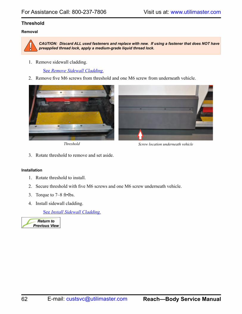
For Assistance Call: 800-237-7806 Visit us at: www.utilimaster.com
62 Reach—Body Service Manual E-mail: [email protected]
Threshold Removal
1. Remove sidewall cladding.
See Remove Sidewall Cladding.2. Remove five M6 screws from threshold and one M6 screw from underneath vehicle.
3. Rotate threshold to remove and set aside.
Installation
1. Rotate threshold to install.
2. Secure threshold with five M6 screws and one M6 screw underneath vehicle.
3. Torque to 7–8 ft•lbs.
4. Install sidewall cladding.
See Install Sidewall Cladding.
Threshold Screw location underneath vehicle
CAUTION: Discard ALL used fasteners and replace with new. If using a fastener that does NOT have preapplied thread lock, apply a medium-grade liquid thread lock.

63
For Assistance Call: 800-237-7806Parts On-line: https://parts.utilimaster.com
Reach—Body Service Manual Fax: 574-862-7637
Window, SliderRemoval
1. Remove cab sliding door.
See Remove Cab Slider Door.2. Remove rivets from sliding window.
See Remove Blind Rivets.3. Lift out window.
4. Remove foam tape and discard.
5. Set window aside.
Installation
1. Place replacement window in door frame and, from inside, mark rivet holes around perimeter of window frame.
2. Drill holes into replacement window frame.
3. Install new foam tape to window.
4. Install window with rivets.
See Install Blind Rivets.5. Install sliding door.
See Install Cab Slider Door.
CAUTION: Discard ALL used fasteners and replace with new. If using a fastener that does NOT have preapplied thread lock, apply a medium-grade liquid thread lock.

For Assistance Call: 800-237-7806 Visit us at: www.utilimaster.com
64 Reach—Body Service Manual E-mail: [email protected]
Handle Removal
1. Remove two Torx® head screws.
2. Set handle aside.Installation
1. Check window for any residual tape and clean with isopropyl alcohol if necessary.
2. Secure pressure-sensitive tape to back of handle.
3. Secure handle with T20 Torx head screws, finishing washers, and retainer buttons.
CAUTION: Discard ALL used fasteners and replace with new. If using a fastener that does NOT have preapplied thread lock, apply a medium-grade liquid thread lock.
Location of Torx head screws

65
For Assistance Call: 800-237-7806Parts On-line: https://parts.utilimaster.com
Reach—Body Service Manual Fax: 574-862-7637
Doors, T-Series Rear Roll-up
NOTE: The information in this document is generic. Images and procedures may differ from those for vehicles you are servicing. Because Utilimaster manufactures customized vehicle bodies, this document cannot list and illustrate every possible option for every vehicle. The most common body options are described here. Use this information as a guideline. Refer also to the door manufacturer's service guide.NOTE: Safety, application, and operation instructions provided by the door manufacturer should always supersede information provided by Utilimaster.
To unlock the door from the outside, insert the key in lock and turn clockwise 1/4 turn until thumb lock pops out. Rotate key counter-clockwise 1/4 turn and remove the key from the lock.To open the door from the outside, push down on the lower door lift handle to relieve tension on the latches, rotate the release handle clockwise until the latches release. To open the door from the inside, push down on the door to relieve tension on latches and push the lever toward the passenger’s side of vehicle until the side latches release. To lock the door from the outside, insert the key and turn clockwise and push in on thumb lock.
Rear roll-up door handle
WARNING: A moving door can cause injury or death. Stand clear of the opening while the door is moving.
WARNING: A roll-up door counterbalance spring is wound under high tension. Only qualified technicians should adjust this spring.
CAUTION: To prevent damage to the cargo or vehicle, be sure that the rear door is closed and latched before driving the vehicle.
WARNING: Do NOT use the rear door pull strap to support yourself when entering or exiting the rear. The strap can break or pull the door down upon you. Use the grab handles to aid getting in and out of the back.
Rear roll-up door latch and grab handle
WARNING: Read the safety and warning decals provided by the manufacturer. Never paint over the decals and replace them if they are faded.
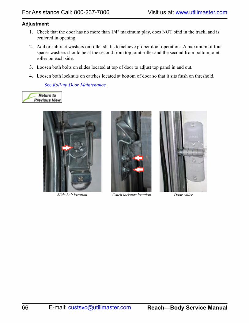
For Assistance Call: 800-237-7806 Visit us at: www.utilimaster.com
66 Reach—Body Service Manual E-mail: [email protected]
Adjustment1. Check that the door has no more than 1/4" maximum play, does NOT bind in the track, and is
centered in opening.
2. Add or subtract washers on roller shafts to achieve proper door operation. A maximum of four spacer washers should be at the second from top joint roller and the second from bottom joint roller on each side.
3. Loosen both bolts on slides located at top of door to adjust top panel in and out.
4. Loosen both locknuts on catches located at bottom of door so that it sits flush on threshold.
See Roll-up Door Maintenance.
Slide bolt location Catch locknuts location Door roller

67
For Assistance Call: 800-237-7806Parts On-line: https://parts.utilimaster.com
Reach—Body Service Manual Fax: 574-862-7637
Removal
1. Close door.
2. Remove cables.
See Remove Cables.3. Remove the hex head bolt and nut from stops
located at the end of the track and remove stops.
4. Slowly move door up and remove from top of track.
Installation1. Lift and slowly slide door into top of tracks.
2. Install cables.
See Install Cables.3. Secure the stops located at the end of the track with hex head bolts, lock washers, and nuts.
Cables
Removal
NOTE: It is recommended to replace both cables even if only one cable is frayed or damaged.
1. Close door.
2. Insert a winding bar that is 1/2" in diameter and 18" long into one of the spring-winding plug holes.
3. Raise the bar to allow insertion of a second winding bar into the lower hole.
4. Release the tension enough to allow the second bar to rest against the top panel.
WARNING: The counterbalance spring is wound under high tension and can cause severe injury or death. Release the tension as described prior to performing repairs.Installation, repairs, and adjustments must be made by trained service personnel using proper tools and instructions.Use two heavy-gauge steel winding bars with the proper dimensions. Do NOT use bent winding bars, screwdrivers, or punches for spring winding.
Stop bolt
Spring-winding plug
WARNING: Do NOT raise the door with the winding bar in place. Raising the door with the winding bar in place can cause injury or damage to the equipment.
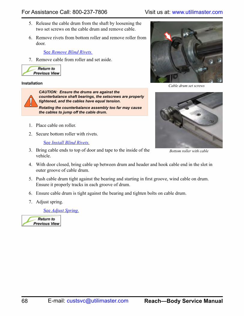
For Assistance Call: 800-237-7806 Visit us at: www.utilimaster.com
68 Reach—Body Service Manual E-mail: [email protected]
5. Release the cable drum from the shaft by loosening the two set screws on the cable drum and remove cable.
6. Remove rivets from bottom roller and remove roller from door.
See Remove Blind Rivets.7. Remove cable from roller and set aside.
Installation
1. Place cable on roller.
2. Secure bottom roller with rivets.
See Install Blind Rivets.3. Bring cable ends to top of door and tape to the inside of the
vehicle.
4. With door closed, bring cable up between drum and header and hook cable end in the slot in outer groove of cable drum.
5. Push cable drum tight against the bearing and starting in first groove, wind cable on drum. Ensure it properly tracks in each groove of drum.
6. Ensure cable drum is tight against the bearing and tighten bolts on cable drum.
7. Adjust spring.
See Adjust Spring.
Bottom roller with cable
Cable drum set screwsCAUTION: Ensure the drums are against the counterbalance shaft bearings, the setscrews are properly tightened, and the cables have equal tension.Rotating the counterbalance assembly too far may cause the cables to jump off the cable drum.

69
For Assistance Call: 800-237-7806Parts On-line: https://parts.utilimaster.com
Reach—Body Service Manual Fax: 574-862-7637
PanelsRemoval
NOTE: Before removing the bottom panel, the cable needs to be removed.See Remove Cables.
NOTE: Remove hardware from panels to be used on replacement panels.1. Close door and clamp track below panel to be removed.
2. Remove rivets in hinges. Insert a punch in one of the rivet holes to stabilize the panel while removing the remaining rivets.
See Remove Blind Rivets.NOTE: If removing the top panel, remove the bolts and washers in both top rollers.
3. Remove the rollers.
See Remove Rollers.4. Lift the door panels, above panel to be replaced, into horizontal track and
secure with clamps on the track.
5. Remove punches and lift out the panel.
Installation
1. Clamp the panel into position and lower the door from the horizontal track.
2. Drill the holes on the new panel, using the holes on the hinge as a guide.
NOTE: If installing the top panel, secure the bolts and washers in both top rollers.3. Install the rollers.
See Install Rollers.4. Secure hinges with rivets.
See Install Blind Rivets.NOTE: If installing the bottom panel, the cables needs to be installed.
See Install Cables.NOTE: Install any applicable hardware on panels.
CAUTION: Do NOT drill through the outside panel of a hollow core door.
Top roller
Door hinge

For Assistance Call: 800-237-7806 Visit us at: www.utilimaster.com
70 Reach—Body Service Manual E-mail: [email protected]
RollersRemoval
1. Open door.
2. Remove rivets from end hinge.
See Remove Blind Rivet.3. Remove roller from track and set aside.
Installation
1. Insert roller into hinge.
2. Place roller into track.
3. Install end hinge with 1/4 x 1-1/8" elevator bolt and nut.
4. Lubricate with a light oil (Utilimaster P/N 04202540).
SealsHeader Seal Removal
1. Remove rear header cladding.
See Remove Header Cladding.2. Remove rivets in extrusion and remove
extrusion.
See Remove Blind Rivets.3. Use a flat-blade screwdriver to pry apart the
crimped extrusion.
4. Remove seal from track and discard.
Header Seal Installation
1. Slide seal into upper track.
2. Crimp the extrusion.
3. Install extrusion with rivets.
See Install Blind Rivets.4. Install rear header cladding.
See Install Header Cladding.
Door roller
Header seal
71
For Assistance Call: 800-237-7806Parts On-line: https://parts.utilimaster.com
Reach—Body Service Manual Fax: 574-862-7637
SpringAdjustment
NOTE: A properly counterbalanced door should remain in the same position when stopped. If the door leaves the floor by itself, the spring is wound too tightly, and a few quarter turns should be released. If the door tends to drop when stopped, a few more quarter turns should be added.NOTE: To determine the amount of turns on a newly installed spring, measure from the bottom of the door to the header. Divide that measurement by ten and then add three. This number is the approximate number of turns needed to wind the spring. Turns are counted by using the chalk marks, which show up as stripes as the spring is wound.
1. Close door and clamp counterbalance shaft from the inside with handle of locking pliers against the ceiling to keep cables tight. Protect the roof from the pliers with a piece of plywood or sheet metal.
2. Insert a heavy-gauge steel winding bar into one of the spring-winding plug holes.
3. Loosen setscrews on spring-winding plug.
4. Insert a winding bar that is 1/2" in diameter and 18" long into one of the spring-winding plug holes.
5. Raise the bar to allow insertion of second winding bar into next spring-winding plug.
6. Continue to raise bar to wind spring.
7. Tighten setscrews.
8. Remove locking pliers and winding bars.
9. Cycle door to check operation.
10. Adjust again if necessary.
11. Lubricate with a light oil (Utilimaster P/N 04202540).

For Assistance Call: 800-237-7806 Visit us at: www.utilimaster.com
72 Reach—Body Service Manual E-mail: [email protected]
Winding counterbalance spring
Right Hand (Curbside)
Left Hand (Roadside)
Chalk mark
Support Bracket
Chalk Mark(Compressed Spring)
Winding Bars (See Dimensions Table)
Locking PliersAgainst Ceiling
Rotate Toward theCeiling to Compress Spring
Spring Winding Plug
Cable
Door Top Panel
Cable Drum
ProtectiveFlat Stock
Setscrew
NOTE: This vehicle was designed using English (S.A.E.) measurements. Utilimaster provides metric conversion equivalents as a courtesy, but Utilimaster does not warrant metric values given in this manual.
Winding Bar DimensionsDoor
ManufacturerDiameter(Inches)
Diameter(Millimeters)
ApproximateLength
TODCO 1/2" 127 mm18" or 46 cm
Whiting 3/8" 95.2 mm

73
For Assistance Call: 800-237-7806Parts On-line: https://parts.utilimaster.com
Reach—Body Service Manual Fax: 574-862-7637
Removal
1. Insert a heavy-gauge steel winding bar into one of the spring-winding plug holes.
2. Loosen the setscrews on the spring-winding plug.
3. Insert a winding bar that is 1/2" in diameter and 18" long into one of the spring-winding plug holes.
4. Lower the bar to allow insertion of second winding bar into next spring-winding plug.
5. Continue to lower bar to release spring.
6. Remove bolts located on anchor brackets.
7. Remove spring and set aside.
Installation
1. Place spring into anchor brackets and secure with bolts, lock washers, and nuts.
2. Run a chalk mark the full length of the spring.
3. Adjust spring.
See Adjust Spring.

For Assistance Call: 800-237-7806 Visit us at: www.utilimaster.com
74 Reach—Body Service Manual E-mail: [email protected]
Doors, W-Series Rear Roll-up
NOTE: The information in this document is generic. Images and procedures may differ from those for vehicles you are servicing. Because Utilimaster manufactures customized vehicle bodies, this document cannot list and illustrate every possible option for every vehicle. The most common body options are described here. Use this information as a guideline. Refer also to the door manufacturer's service guide.NOTE: Safety, application, and operation instructions provided by the door manufacturer should always supersede information provided by Utilimaster.
To unlock the door from the outside, insert the key in lock and turn clockwise 1/4 turn until thumb lock pops out. Rotate key counter-clockwise 1/4 turn and remove the key from the lock.To open the door from the outside, push down on the lower door lift handle to relieve tension on the latches, rotate the release handle clockwise until the latches release. To open the door from the inside, push down on the door to relieve tension on latches and push the lever toward the passenger’s side of vehicle until the side latches release. To lock the door from the outside, insert the key and turn clockwise and push in on thumb lock.
Rear roll-up door handle
WARNING: A moving door can cause injury or death. Stand clear of the opening while the door is moving.
WARNING: A roll-up door counterbalance spring is wound under high tension. Only qualified technicians should adjust this spring.
CAUTION: To prevent damage to the cargo or vehicle, be sure that the rear door is closed and latched before driving the vehicle.
Rear roll-up door latch
WARNING: Read the safety and warning decals provided by the manufacturer. Never paint over the decals and replace them if they are faded.
WARNING: Do NOT use the rear door pull strap to support yourself when entering or exiting the rear. The strap can break or pull the door down upon you. Use the grab handles to aid getting in and out of the back.

75
For Assistance Call: 800-237-7806Parts On-line: https://parts.utilimaster.com
Reach—Body Service Manual Fax: 574-862-7637
AdjustmentNOTE: Adjusting the roller bracket up moves the panel in. Adjusting the roller bracket down moves the panel out. The door may jam if adjusted too tightly.
1. Check that the door has no more than 1/4" maximum play, does NOT bind in the track, and is centered in opening.
2. Add or subtract washers on roller shafts to achieve proper door operation. A maximum of five spacer washers should be at the second from top roller and the second from bottom roller on each side. Loosen nuts on top roller bracket.
3. Position top roller brackets so that the top panel is vertical and seals along both the top and sides.
4. Tighten nuts.
See Roll-up Door Maintenance.
Nut location on top roller bracket

For Assistance Call: 800-237-7806 Visit us at: www.utilimaster.com
76 Reach—Body Service Manual E-mail: [email protected]
Removal
1. Close door.
2. Remove cables.
See Remove Cables.3. Remove the nuts, washers, and bolts from stops located at the end
of the track and set aside.
4. Slowly move door up and remove from tracks.
Installation1. Lift and slowly slide door into top of tracks.
2. Install cables.
See Install Cables.3. Secure stops located at the end of the track with bolts, washers, and nuts.
4. Adjust spring.
See Adjust Spring.
CablesRemoval
NOTE: It is recommended to replace both cables even if only one cable is frayed or damaged.
1. Close door.
2. Insert a winding bar that is 1/2" in diameter by 18" long into one of the spring-winding plug holes.
3. Raise the bar to allow insertion of a second winding bar into the lower hole.
4. Release the tension enough to allow the second bar to rest against the top panel.
WARNING: The counterbalance springs are wound under high tension and can cause severe injury or death. Release the tension as described prior to performing repairs.Installation, repairs, and adjustments must be made by trained service personnel using proper tools and instructions.Use two heavy-gauge steel winding bars with the proper dimensions. Do NOT use bent winding bars, screwdrivers, or punches for spring winding.
Stop bolt
WARNING: To avoid injury or damage to the equipment, do NOT raise the door with the winding bar in place.
Spring winding plug holes

77
For Assistance Call: 800-237-7806Parts On-line: https://parts.utilimaster.com
Reach—Body Service Manual Fax: 574-862-7637
5. Release the cable drum from the shaft by loosening the two set screws on the cable drum and remove cable.
6. Remove the cotter and anchor pins to remove cable from bottom door panel.
Installation
NOTE: The cable must be wound from the outermost groove toward the inside of the drum.1. Secure the cable end to the anchor bracket with an anchor pin.
2. Secure anchor pin with a cotter pin.
3. Bring cable ends to top of door and tape to the inside of vehicle.
4. With door closed, bring cable up between drum and header and hook cable end in the slot in outer groove of cable drum.
5. Push cable drum tight against the bearing, and starting in first groove, wind cable on drum. Ensure it properly tracks in each groove of drum.
6. Ensure cable drum is tight against the bearing and tighten setscrews.
7. Adjust spring.
See Adjust Spring.
Cable drum Cotter and anchor pins
CAUTION: Ensure the drums are against the counterbalance shaft bearings, the setscrews are properly tightened, and the cables have equal tension.Rotating the counterbalance assembly too far may cause the cables to jump off the cable drum.

For Assistance Call: 800-237-7806 Visit us at: www.utilimaster.com
78 Reach—Body Service Manual E-mail: [email protected]
PanelsRemoval
NOTE: Before removing the bottom panel, the cables needs to be removed.See Remove Cables.
NOTE: Remove hardware from panels to be used on replacement panels.1. Close door and clamp track below panel to be
removed.
2. Remove rivets in hinges. Insert a punch in one of the rivet holes to stabilize the panel while removing the remaining rivets.
See Remove Blind Rivets.NOTE: If removing the top panel, remove the bolts and washers in both top rollers.
3. Remove rollers.
See Remove Rollers.4. Lift the door panels, above panel to be replaced,
into horizontal track and secure with clamps on the track.
5. Remove punches and lift out the panel.
CAUTION: Do NOT drill through the outside panel of a hollow core door.
Top roller bracket
Roller bracket

79
For Assistance Call: 800-237-7806Parts On-line: https://parts.utilimaster.com
Reach—Body Service Manual Fax: 574-862-7637
Installation
1. Clamp the panel into position and lower the door from the horizontal track.
2. Drill the holes on the new panel, using the holes on the hinge as a guide.
NOTE: If installing the top panel, secure the bolts and washers in both top rollers.
3. Install rollers.
See Install Rollers.4. Secure hinges with rivets.
See Install Blind Rivets.NOTE: If installing the bottom panel, the cables need to be installed.
See Install Cables.NOTE: Install any applicable hardware on panels.
CAUTION: Do NOT drill through the outside panel of a hollow core door.
Top roller bracket
Roller bracket

For Assistance Call: 800-237-7806 Visit us at: www.utilimaster.com
80 Reach—Body Service Manual E-mail: [email protected]
RollersRemoval
1. Open door.
2. Remove nuts that secure the roller retainer.
3. Remove roller from track and set aside.
Installation
1. Insert roller into retainer.
2. Place roller into track.
3. Replace the retainer and tighten the nuts.
4. Lubricate with a light oil (Utilimaster P/N 04202540).
SealsBrush Seal Removal
1. Open door.
2. Remove rivets.
See Remove Blind Rivets.3. Use a flat-blade screwdriver to pry apart the crimped
extrusion.
4. Remove seal and discard.
Brush Seal Installation
1. Test fit brush seal and cut to proper length with bolt cutters.
2. Crimp the extrusion.
3. Secure seal with rivets.
See Install Blind Rivets.
Bottom roller bracket
Roller bracket
Brush seal

81
For Assistance Call: 800-237-7806Parts On-line: https://parts.utilimaster.com
Reach—Body Service Manual Fax: 574-862-7637
Top Seal Removal
1. Open door and clamp track to prevent door from moving.
2. Use a flat-blade screwdriver to pry apart the crimped extrusion and remove seal.
Top Seal Installation
1. Slide seal into extrusion.
2. Crimp the extrusion.
Threshold Seal Removal
1. Open door and clamp track to prevent door from moving.
2. Remove the Phillips head screws from the threshold seal.
3. Remove seal and discard.
Threshold Seal Installation
1. Place the seal, angle edge first, into the extrusion and rotate into position.
2. Secure with #8 screws.
Top seal Bottom seal

For Assistance Call: 800-237-7806 Visit us at: www.utilimaster.com
82 Reach—Body Service Manual E-mail: [email protected]
SpringsAdjustment
NOTE: A properly counterbalanced door should remain in the same position when stopped. If the door leaves the floor by itself, the spring is wound too tightly, and a few quarter turns should be released. If the door tends to drop when stopped, a few more quarter turns should be added.NOTE: To determine the amount of turns on a newly installed spring, measure from the bottom of the door to the header. Divide that measurement by ten and then add three. This number is the approximate number of turns needed to wind the spring. Turns are counted by using the chalk marks, which show up as stripes as the spring is wound.
1. Close door and clamp counterbalance shaft from the inside with handle of locking pliers against the ceiling to keep cables tight. Protect the roof from the pliers with a piece of plywood or sheet metal.
2. Insert a heavy-gauge steel winding bar into one of the spring-winding plug holes.
3. Loosen setscrews on spring-winding plug.
4. Insert a winding bar that is 1/2" in diameter and 18" long into one of the spring-winding plug holes.
5. Raise the bar to allow insertion of second winding bar into next spring-winding plug.
6. Continue to raise bar to wind spring.
7. Tighten setscrews.
8. Remove locking pliers and winding bars.
9. Cycle door to check operation.
10. Adjust again if necessary.
11. Lubricate with a light oil (Utilimaster P/N 04202540).

83
For Assistance Call: 800-237-7806Parts On-line: https://parts.utilimaster.com
Reach—Body Service Manual Fax: 574-862-7637
Winding counterbalance spring
Right Hand (Curbside)
Left Hand (Roadside)
Chalk mark
Support Bracket
Chalk Mark(Compressed Spring)
Winding Bars (See Dimensions Table)
Locking PliersAgainst Ceiling
Rotate Toward theCeiling to Compress Spring
Spring Winding Plug
Cable
Door Top Panel
Cable Drum
ProtectiveFlat Stock
Setscrew
NOTE: This vehicle was designed using English (S.A.E.) measurements. Utilimaster provides metric conversion equivalents as a courtesy, but Utilimaster does not warrant metric values given in this manual.
Winding Bar DimensionsDoor
ManufacturerDiameter(Inches)
Diameter(Millimeters)
ApproximateLength
TODCO 1/2" 127 mm18" or 46 cm
Whiting 3/8" 95.2 mm

For Assistance Call: 800-237-7806 Visit us at: www.utilimaster.com
84 Reach—Body Service Manual E-mail: [email protected]
Removal
1. Insert a heavy-gauge steel winding bar into one of the spring-winding plug holes.
2. Loosen the setscrews on the spring-winding plug.
3. Insert a winding bar that is 1/2" in diameter and 18" long into one of the spring-winding plug holes.
4. Lower the bar to allow insertion of second winding bar into next spring-winding plug.
5. Continue to lower bar to release spring.
6. Remove bolts located on anchor brackets.
7. Remove spring and set aside.
Installation
1. Place spring into anchor brackets and secure with bolts, lock washers, and nuts.
2. Run a chalk mark the full length of the spring.
3. Adjust spring.
See Adjust Spring.

85
For Assistance Call: 800-237-7806Parts On-line: https://parts.utilimaster.com
Reach—Body Service Manual Fax: 574-862-7637
Engine CoverRemoval
1. Release two rubber latches on sides of engine cover.
2. Remove cover and set aside.
Installation1. Slide cover between guides.
2. Secure two rubber latches on both sides of engine cover.
GasketRemoval
1. Remove engine cover.
2. Remove gasket and discard.
Installation
1. Press gasket onto engine cover.
2. Install engine cover.
StrapRemoval
1. Use a die grinder to cut off the pin holding the strap.
2. Remove strap and discard.
Installation
1. Secure strap to mounting bracket with a compatible bolt and lock nut.
Engine cover
Engine cover gasket
Fastener on strap
Replacement bolt and nut on strap

For Assistance Call: 800-237-7806 Visit us at: www.utilimaster.com
86 Reach—Body Service Manual E-mail: [email protected]
FendersFront Cladding
See Cladding, Front Fender.Front Quarter FenderRemoval
NOTE: On driver's side, remove mirror head before removing front quarter fender.See Remove Mirrors.
1. Remove front fender cladding.
See Remove Front Fender Cladding.2. Remove three M6 screws behind A-pillar seal.
3. Remove lower M6 screw in A-pillar trim.
4. Remove two M6 screws along the top rail of engine compartment.
CAUTION: Discard ALL used fasteners and replace with new. If using a fastener that does NOT have preapplied thread lock, apply a medium-grade liquid thread lock.
Screw location behind A-pillar seal
Screw location in A-pillar Screw location on top rail of engine compartment

87
For Assistance Call: 800-237-7806Parts On-line: https://parts.utilimaster.com
Reach—Body Service Manual Fax: 574-862-7637
5. Remove two M6 screws on quarter fender.
6. Remove two M6 screws on outside edge of headlight bezel.
7. Set fender aside.
Installation
1. Secure two M6 screws on outside of headlight bezel.
2. Secure two M6 screws along top rail of the engine compartment.
3. Secure one M6 screw in lower portion of A-pillar.
4. Secure three M6 screws behind A-pillar seal.
5. Torque to 7–8 ft•lbs.
6. Install front fender cladding.
See Install Front Fender Cladding.
Screw location in headlight bezel
Screw location in A-pillar Screw location behind A-pillar seal
CAUTION: Discard ALL used fasteners and replace with new. If using a fastener that does NOT have preapplied thread lock, apply a medium-grade liquid thread lock.
Screw location on quarter fender

For Assistance Call: 800-237-7806 Visit us at: www.utilimaster.com
88 Reach—Body Service Manual E-mail: [email protected]
Front Wheel LinerRemoval
1. Remove three #8 Phillips head screws in front wheel liner.
2. Set front wheel liner aside.
Installation
1. Secure front wheel liner with three #8 Phillips head screws.
Sidewall CladdingSee Cladding, Sidewall. Screw locations in wheel liner
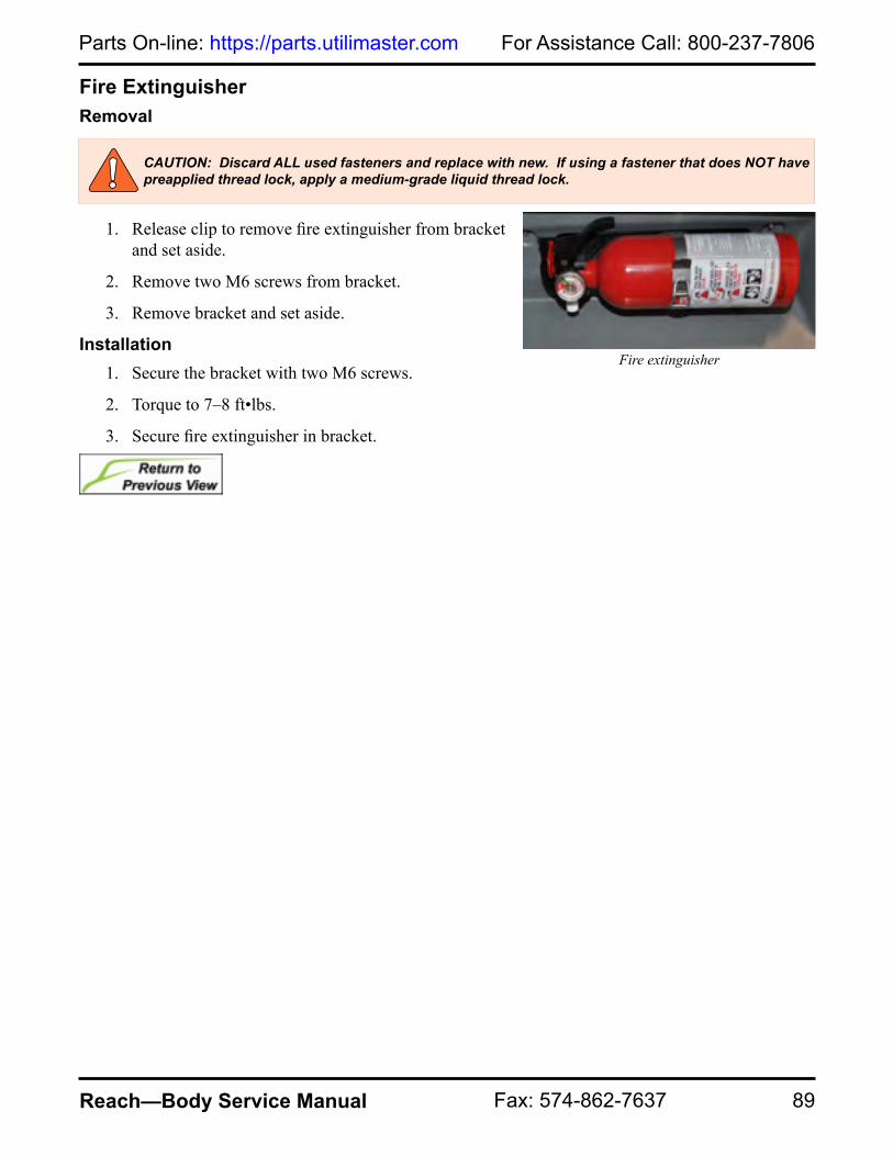
89
For Assistance Call: 800-237-7806Parts On-line: https://parts.utilimaster.com
Reach—Body Service Manual Fax: 574-862-7637
Fire ExtinguisherRemoval
1. Release clip to remove fire extinguisher from bracket and set aside.
2. Remove two M6 screws from bracket.
3. Remove bracket and set aside.
Installation1. Secure the bracket with two M6 screws.
2. Torque to 7–8 ft•lbs.
3. Secure fire extinguisher in bracket.
CAUTION: Discard ALL used fasteners and replace with new. If using a fastener that does NOT have preapplied thread lock, apply a medium-grade liquid thread lock.
Fire extinguisher
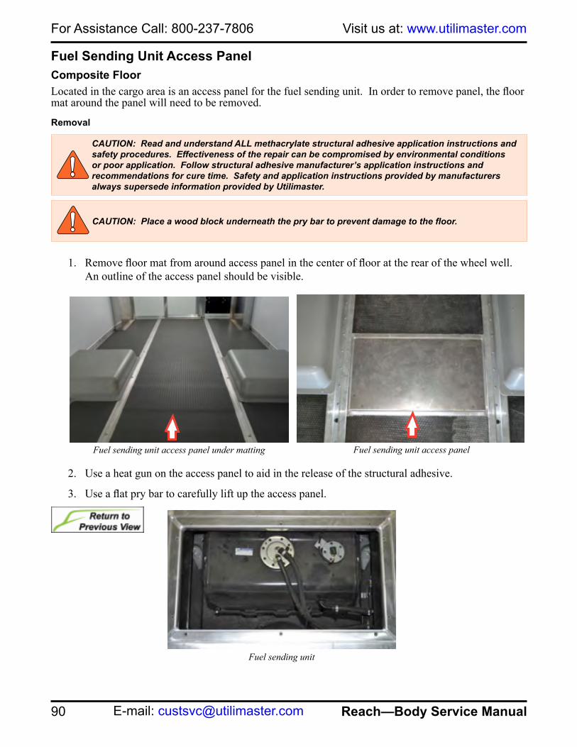
For Assistance Call: 800-237-7806 Visit us at: www.utilimaster.com
90 Reach—Body Service Manual E-mail: [email protected]
Fuel Sending Unit Access PanelComposite FloorLocated in the cargo area is an access panel for the fuel sending unit. In order to remove panel, the floor mat around the panel will need to be removed.
Removal
1. Remove floor mat from around access panel in the center of floor at the rear of the wheel well. An outline of the access panel should be visible.
2. Use a heat gun on the access panel to aid in the release of the structural adhesive.
3. Use a flat pry bar to carefully lift up the access panel.
CAUTION: Read and understand ALL methacrylate structural adhesive application instructions and safety procedures. Effectiveness of the repair can be compromised by environmental conditions or poor application. Follow structural adhesive manufacturer’s application instructions and recommendations for cure time. Safety and application instructions provided by manufacturers always supersede information provided by Utilimaster.
Fuel sending unit access panel under matting Fuel sending unit access panel
CAUTION: Place a wood block underneath the pry bar to prevent damage to the floor.
Fuel sending unit

91
For Assistance Call: 800-237-7806Parts On-line: https://parts.utilimaster.com
Reach—Body Service Manual Fax: 574-862-7637
Installation
1. Use a grinder to clean off any old structural adhesive.
2. Clean contact surfaces at floor and on panel with isopropyl alcohol and allow to dry.
3. Assemble structural adhesive gun by removing the cap from the structural adhesive cartridge and attaching the mixing tube to the cartridge, pressing firmly.
4. Place the plunger into the back of the cartridge.
5. Dispense structural adhesive on a scrap piece of cardboard until the mixture comes out green. The bead will be approximately the length of the mixer tip which means the structural adhesive is adequately mixed.
6. Apply structural adhesive approximately 1” in from the perimeter of the access panel.
7. Center access panel over opening in floor and press firmly.
8. Apply weight to the panel and allow structural adhesive to bond to floor.
9. Secure floor mat to floor with spray structural adhesive and roll with a floor weight to bond.
Purge Mixer Tip
CAUTION: The structural adhesive will cure in approximately six minutes once it is exposed to air. Do NOT interrupt or delay the process once the structural adhesive application has begun.
Adhesive cartridge and plunger assembly
Sleeve Adapter
Cartridge
Plunger
Mixer TipSleeve
Cartridge
Plunger
Caulking Gun

For Assistance Call: 800-237-7806 Visit us at: www.utilimaster.com
92 Reach—Body Service Manual E-mail: [email protected]
GlassTools and Materials
The following information can be shared with auto glass shops.If you do the job yourself, you will need the following:
• Replacement glassWindshield glass–laminated safety glass (P/N 09801779)
Driver's side quarter window glass (P/N 09801831)
Passenger's side quarter window glass (P/N 09801780)• Windshield pneumatic knife (optional)• Wire style cutter• Isopropyl alcohol• Glass bonding replacement kit• Masking tape• Caulking gun• Medium Red Scotch Brite™ (to roughen surfaces)• Clean cotton rag or lint-free paper towel• Glass replacement tool kit(s)
WARNING: Use rubber gloves and any appropriate breathing apparatus as recommended by the manufacturer of the kit.WARNING: To avoid injuring yourself or others, use extreme care when handling glass, the pneumatic knife, and utility knife.
CAUTION: A properly bonded windshield is critical to the structural integrity of the vehicle. Utilimaster recommends that professional automotive glass specialists replace the windshield and windows.Glass adhesives and sealants have a short shelf life. Close attention must be paid to cleaning surfaces and to timing during installation.

93
For Assistance Call: 800-237-7806Parts On-line: https://parts.utilimaster.com
Reach—Body Service Manual Fax: 574-862-7637
Windshield Tool Kit (P/N 23003394SK)The Utilimaster windshield replacement tool kit consists of:
• Windshield support blocks (P/N F542662)• Windshield spacers (P/N 08612036)• Poly-stick• Utility knife
Driver’s Side Quarter Window Glass Tool Kit (P/N 23003395SK)The Utilimaster driver's side quarter glass replacement tool kit consists of:
• Quarter glass support blocks (P/N T542683)• Quarter glass spacers (P/N 08612037)• Quarter glass trim, driver's side (P/N 05705843)• Poly-stick• Utility knife
Passenger’s Side Quarter Window Glass Tool Kit (P/N 23003396SK)The Utilimaster driver's side quarter glass replacement tool kit consists of:
• Quarter glass support blocks (P/N T542683)• Quarter glass spacers (P/N 08612037)• Quarter glass trim, passenger's side (P/N 05705844)• Poly-stick• Utility knife
Glass Bonding Material Kit (P/N 23005015SK)The Utilimaster bonded window replacement material kit consists of:Activator (P/N 12605959)Primer (P/N 12605827)Urethane Adhesive Sealant (P/N 12605956)
Material kit

For Assistance Call: 800-237-7806 Visit us at: www.utilimaster.com
94 Reach—Body Service Manual E-mail: [email protected]
Windshield Removal
1. Remove A-Pillar trim.
See Remove A-Pillar Trim.2. Remove hood.
See Remove Hood.3. Remove wiper arms.
See Remove Wiper Arms.4. Remove six M4 screws from the top of leaf screen.
5. Remove five #8 Phillips head screws from the bottom of the leaf screen and set leaf screen aside.
6. From the outside of the vehicle, insert the blade of a windshield pneumatic knife, utility knife, or wire style cutter to cut out the urethane seal around perimeter of windshield. Try to leave at least 1/8" thick section of sealant on the frame.
7. Carefully remove the damaged glass and discard.
WARNING: Use extreme caution to avoid injuring yourself or others when cutting the sealant.
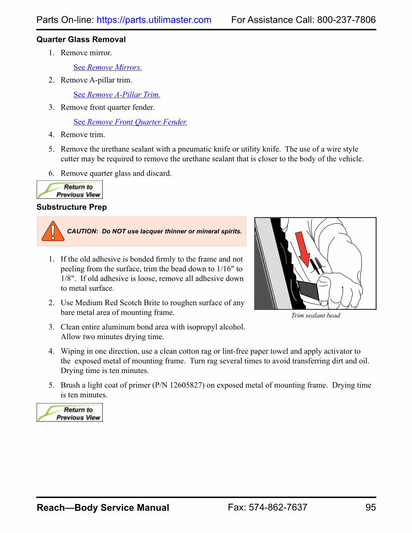
95
For Assistance Call: 800-237-7806Parts On-line: https://parts.utilimaster.com
Reach—Body Service Manual Fax: 574-862-7637
Quarter Glass Removal1. Remove mirror.
See Remove Mirrors.2. Remove A-pillar trim.
See Remove A-Pillar Trim.3. Remove front quarter fender.
See Remove Front Quarter Fender.4. Remove trim.
5. Remove the urethane sealant with a pneumatic knife or utility knife. The use of a wire style cutter may be required to remove the urethane sealant that is closer to the body of the vehicle.
6. Remove quarter glass and discard.
Substructure Prep
1. If the old adhesive is bonded firmly to the frame and not peeling from the surface, trim the bead down to 1/16" to 1/8". If old adhesive is loose, remove all adhesive down to metal surface.
2. Use Medium Red Scotch Brite to roughen surface of any bare metal area of mounting frame.
3. Clean entire aluminum bond area with isopropyl alcohol. Allow two minutes drying time.
4. Wiping in one direction, use a clean cotton rag or lint-free paper towel and apply activator to the exposed metal of mounting frame. Turn rag several times to avoid transferring dirt and oil. Drying time is ten minutes.
5. Brush a light coat of primer (P/N 12605827) on exposed metal of mounting frame. Drying time is ten minutes.
Trim sealant bead
CAUTION: Do NOT use lacquer thinner or mineral spirits.

For Assistance Call: 800-237-7806 Visit us at: www.utilimaster.com
96 Reach—Body Service Manual E-mail: [email protected]
Glass Prep and Bonding
1. For windshield replacement, set the nylon windshield support blocks (P/N F542662) on the support stops located at the bottom of the windshield.
2. Check replacement window for fit.
3. Clean glass with 2-to-1 mixture of isopropyl alcohol and water. Drying time is two minutes. Avoid heavy soaps or ammonia. Auto glass replacement dealers also have recommended cleaners.
4. Wiping in one direction, use a clean cotton rag or lint-free paper towel and apply the Sika activator on the bonding area (frit band). Turn rag several times to avoid transferring dirt and oil. Drying time is ten minutes. Finish the installation process within two hours.
5. For windshield installation, apply spacers on the inside of the glass in all four corners and in the center on the top and bottom.
Windshield support block
CAUTION: Bonding glass is a sensitive process. All steps should be followed closely and without substitutions. Professional automotive glass installers are recommended.
Spacer placement for windshield
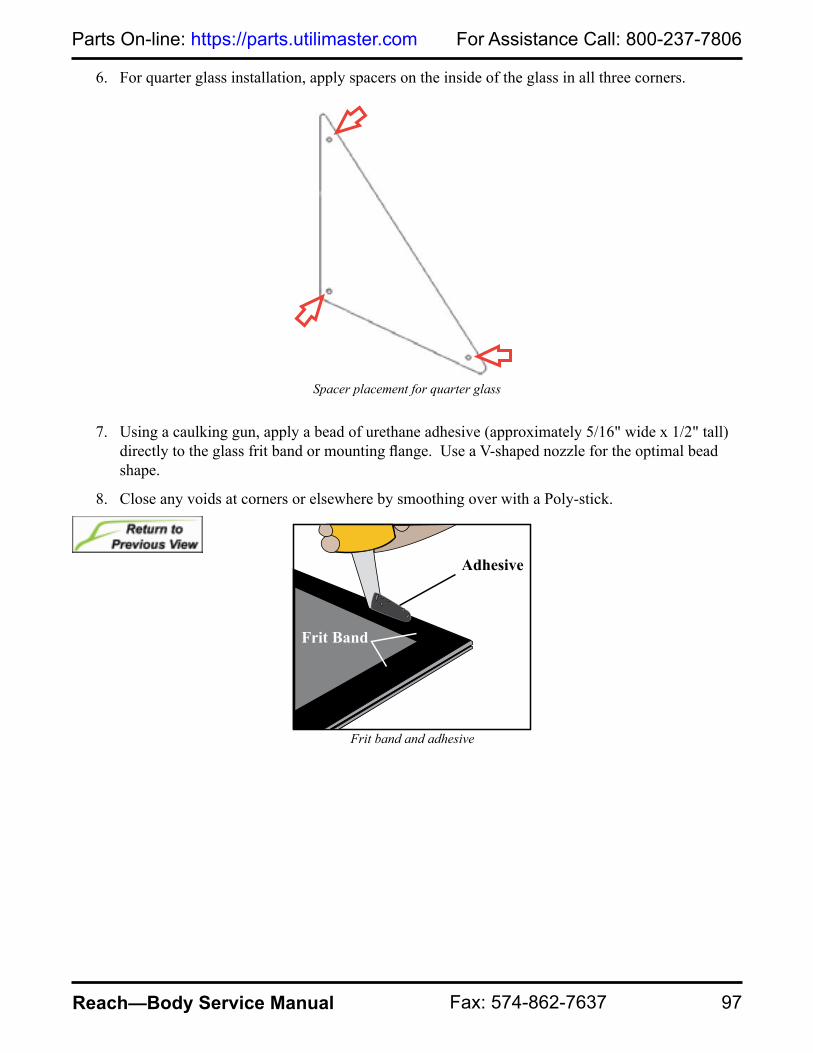
97
For Assistance Call: 800-237-7806Parts On-line: https://parts.utilimaster.com
Reach—Body Service Manual Fax: 574-862-7637
6. For quarter glass installation, apply spacers on the inside of the glass in all three corners.
7. Using a caulking gun, apply a bead of urethane adhesive (approximately 5/16" wide x 1/2" tall) directly to the glass frit band or mounting flange. Use a V-shaped nozzle for the optimal bead shape.
8. Close any voids at corners or elsewhere by smoothing over with a Poly-stick.
Spacer placement for quarter glass
Adhesive
Frit Band
Frit band and adhesive

For Assistance Call: 800-237-7806 Visit us at: www.utilimaster.com
98 Reach—Body Service Manual E-mail: [email protected]
Windshield Installation
NOTE: Recommended minimum thickness of adhesive layer after installation is 1/4".1. Install glass onto vehicle and align to correct
position using the support blocks.
2. Press gently around the entire perimeter of glass to make a good adhesive contact. Use the Poly-stick to clean up any excess adhesive.
3. Clean area with a mild soap solution (use sparingly).
4. Secure top of leaf screen with six M4 screws.
5. Torque to 15–25 ft•lbs.
6. Secure bottom of leaf screen with five #8 Phillips head screws.
7. Install wiper arms.
See Install Wiper Arms.8. Install hood.
See Install the Hood.9. Install A-pillar trim.
See Install A-Pillar Trim.
Install glass
CAUTION: Glass must be installed within ten minutes of applying adhesive to ensure a good bond.
CAUTION: Do NOT use mineral spirits or alcohol.
CAUTION: Do NOT wash the windows for at least 24 hours following installation. Chemicals like those found in washer fluid can retard the adhesives.
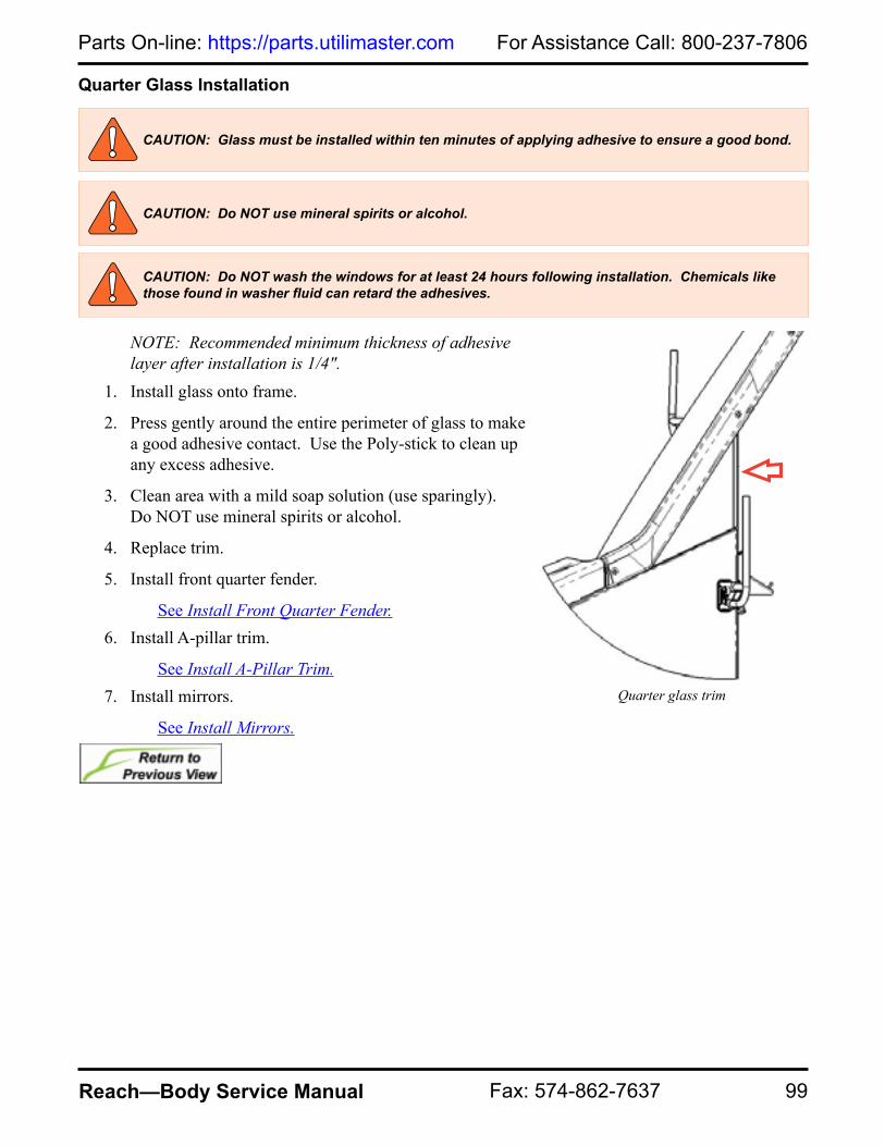
99
For Assistance Call: 800-237-7806Parts On-line: https://parts.utilimaster.com
Reach—Body Service Manual Fax: 574-862-7637
Quarter Glass Installation
NOTE: Recommended minimum thickness of adhesive layer after installation is 1/4".
1. Install glass onto frame.
2. Press gently around the entire perimeter of glass to make a good adhesive contact. Use the Poly-stick to clean up any excess adhesive.
3. Clean area with a mild soap solution (use sparingly). Do NOT use mineral spirits or alcohol.
4. Replace trim.
5. Install front quarter fender.
See Install Front Quarter Fender.6. Install A-pillar trim.
See Install A-Pillar Trim.7. Install mirrors.
See Install Mirrors.
CAUTION: Glass must be installed within ten minutes of applying adhesive to ensure a good bond.
CAUTION: Do NOT use mineral spirits or alcohol.
CAUTION: Do NOT wash the windows for at least 24 hours following installation. Chemicals like those found in washer fluid can retard the adhesives.
Quarter glass trim

For Assistance Call: 800-237-7806 Visit us at: www.utilimaster.com
100 Reach—Body Service Manual E-mail: [email protected]
GrilleRemoval
1. Open hood.
See Open Hood.2. Remove eight pine-tree fasteners from grille.
See Remove Pine-Tree Fasteners.3. Set grille aside.
Installation1. Install eight pine-tree fasteners to the grille.
See Install Pine-Tree Fasteners.
CAUTION: Discard ALL used fasteners and replace with new. If using a fastener that does NOT have preapplied thread lock, apply a medium-grade liquid thread lock.
Grille

101
For Assistance Call: 800-237-7806Parts On-line: https://parts.utilimaster.com
Reach—Body Service Manual Fax: 574-862-7637
Grille ScreenRemoval
1. Open hood.
See Open Hood.2. Remove grille.
See Remove Grille.3. Remove pine-tree fasteners.
See Remove Pine-Tree Fasteners.
Installation
1. Install pine-tree fasteners.
See Install Pine-Tree Fasteners.2. Install grille.
See Install Grille.
CAUTION: Discard ALL used fasteners and replace with new. If using a fastener that does NOT have preapplied thread lock, apply a medium-grade liquid thread lock.

For Assistance Call: 800-237-7806 Visit us at: www.utilimaster.com
102 Reach—Body Service Manual E-mail: [email protected]
Handrail and Grab HandlesGrab Handle, A-PillarRemoval
1. Remove four M6 screws from A-pillar grab handle and set aside.
Installation
2. Secure grab handle to A-pillar with four M6 screws.
3. Torque to 7–8 ft•lbs.
Grab Handle, CargoRemoval
1. Remove the four M8 bolts.
2. Set grab handle aside.
Installation
1. Secure the mounting brackets with four M8 bolts.
2. Torque to 17–21 ft•lbs.
CAUTION: Discard ALL used fasteners and replace with new. If using a fastener that does NOT have preapplied thread lock, apply a medium-grade liquid thread lock.
A-pillar grab handle
CAUTION: Discard ALL used fasteners and replace with new. If using a fastener that does NOT have preapplied thread lock, apply a medium-grade liquid thread lock.
Bolt location on rear grab handle

103
For Assistance Call: 800-237-7806Parts On-line: https://parts.utilimaster.com
Reach—Body Service Manual Fax: 574-862-7637
HandrailRemoval
1. Remove fuse cover panel.
See Remove Fuse Cover Panel.2. Remove fire extinguisher.
See Remove Fire Extinguisher.3. Remove washer bottle panel.
See Remove Washer Bottle Panel.4. Remove front wheel liner.
See Remove Front Wheel Liner.5. Remove two M8 bolts at the lower handrail from behind the
wheel liner.
6. Remove M6 bolt from upper handrail mounting bracket.
7. Remove handrail and set aside.
Installation
1. Secure handrail to upper mounting bracket with M6 bolt.
2. Torque to 7–8 ft•lbs.
3. Secure bottom of handrail with two M8 bolts from inside the wheel liner.
4. Torque to 17–21 ft•lbs.
5. Install front wheel liner.
See Install Front Wheel Liner.6. Install washer bottle panel.
See Install Washer Bottle Panel.7. Install fuse cover panel.
See Install Fuse Cover Panel.
CAUTION: Discard ALL used fasteners and replace with new. If using a fastener that does NOT have preapplied thread lock, apply a medium-grade liquid thread lock.
Handrail

For Assistance Call: 800-237-7806 Visit us at: www.utilimaster.com
104 Reach—Body Service Manual E-mail: [email protected]
Heater
BLOWER MOTOR
COMPRESSORCLUTCH RELAY
CONDENSERFAN RELAYRECIRCULATION
DOOR SERVO
POWERFAN RELAYTHERMOSTAT
EVAPORATORHEATER CORE
DEFROSTDOOR SERVO
CONTROL MODULEDASH DOOR SERVO
FLOOR DOOR SERVO
RETURN HOSE
SUPPLY HOSE
COOLANT VALVE
TO HEATER
RETURN HOSE
Heater plenum with air-conditioning viewed from inside.
Heater hose routing viewed from under the hood.

105
For Assistance Call: 800-237-7806Parts On-line: https://parts.utilimaster.com
Reach—Body Service Manual Fax: 574-862-7637
Blower MotorThe blower motor is located on the passenger side of the vehicle.
NOTE: 1/4" drive ratchet with magnetic sockets, a 5/16" offset ratchet wrench or gear wrench, and a 1/4" drive shallow socket will make the process easier.
Removal
NOTE: Keep all hardware for reinstallation. NOTE: The thermostat is located above the mode (servo) motor mounted to the left of the blower housing.
1. Remove dash valance panel.
See Remove Dash Valance Panel.2. Disconnect the wires from the thermostat and servo motor.
3. Remove three locknuts and nylon spacers from motor and set aside.
WARNING: Utilimaster recommends the only a licensed/certified automotive technician services the vehicle's air-conditioning system.
Thermostat and servo motor wires

For Assistance Call: 800-237-7806 Visit us at: www.utilimaster.com
106 Reach—Body Service Manual E-mail: [email protected]
4. Remove one #10 x 1/2" screw from the blower motor support bracket to the right of the relays.
5. Remove one #10 x 1/2" screw from the blower motor support bracket located above the servo motor.
Screw on right-hand side of blower motor support bracket
Screw on left-hand side of blower motor support bracket

107
For Assistance Call: 800-237-7806Parts On-line: https://parts.utilimaster.com
Reach—Body Service Manual Fax: 574-862-7637
6. Remove the #10 x 1/2" screws in the three P-clamps located on the blower housing.
7. Remove the six #10 x 1/2" screws from top cover of the blower housing.
8. Use a pair of needle nose pliers to remove blower motor wire grommet.
Screws on cover of blower housing
P-clamps
Blower motor wire grommet

For Assistance Call: 800-237-7806 Visit us at: www.utilimaster.com
108 Reach—Body Service Manual E-mail: [email protected]
9. Remove a section of wires from the convoluted tubing and slide wires and tubing through slot in blower housing. Remove case top and set aside.
10. Use a ratchet wrench or gear wrench to remove four #10 x 1/2" screws from the blower housing.
Pull wires and convoluted tubing out separately.
Screws on blower motor housing

109
For Assistance Call: 800-237-7806Parts On-line: https://parts.utilimaster.com
Reach—Body Service Manual Fax: 574-862-7637
11. Remove one #10 x 1/2" screw from the blower housing above relays.
12. Remove two 1/4-20 bolts and flat washers from the blower housing and set housing aside.
Screw on blower motor housing
Bolts on blower motor housing

For Assistance Call: 800-237-7806 Visit us at: www.utilimaster.com
110 Reach—Body Service Manual E-mail: [email protected]
13. Remove four 3/8" nuts and bracket that secure the motor to housing. Remove motor from housing.
14. Use a screwdriver to disconnect blower harness.
Installation
1. Secure the blower harness to the blower motor.
2. Secure the motor to the blower mounting plate and bracket with four 3/8" nuts.
Nuts that secure motor to housing
Blower harness
Nuts that secure motor to housing

111
For Assistance Call: 800-237-7806Parts On-line: https://parts.utilimaster.com
Reach—Body Service Manual Fax: 574-862-7637
3. Secure blower housing with two flat washers and two 1/4-20 bolts.
4. Secure housing above the relays with one #10 x 1/2" screw.
Screw on blower motor housing
Bolts on blower motor housing

For Assistance Call: 800-237-7806 Visit us at: www.utilimaster.com
112 Reach—Body Service Manual E-mail: [email protected]
5. Secure the end of housing with four #10 x 1/2" screws.
6. Place case top on the blower housing and slide wires and convoluted tubing through slot in blower housing. Place wires into convoluted tubing.
Place wires into convoluted tubing.
Screws on blower motor housing
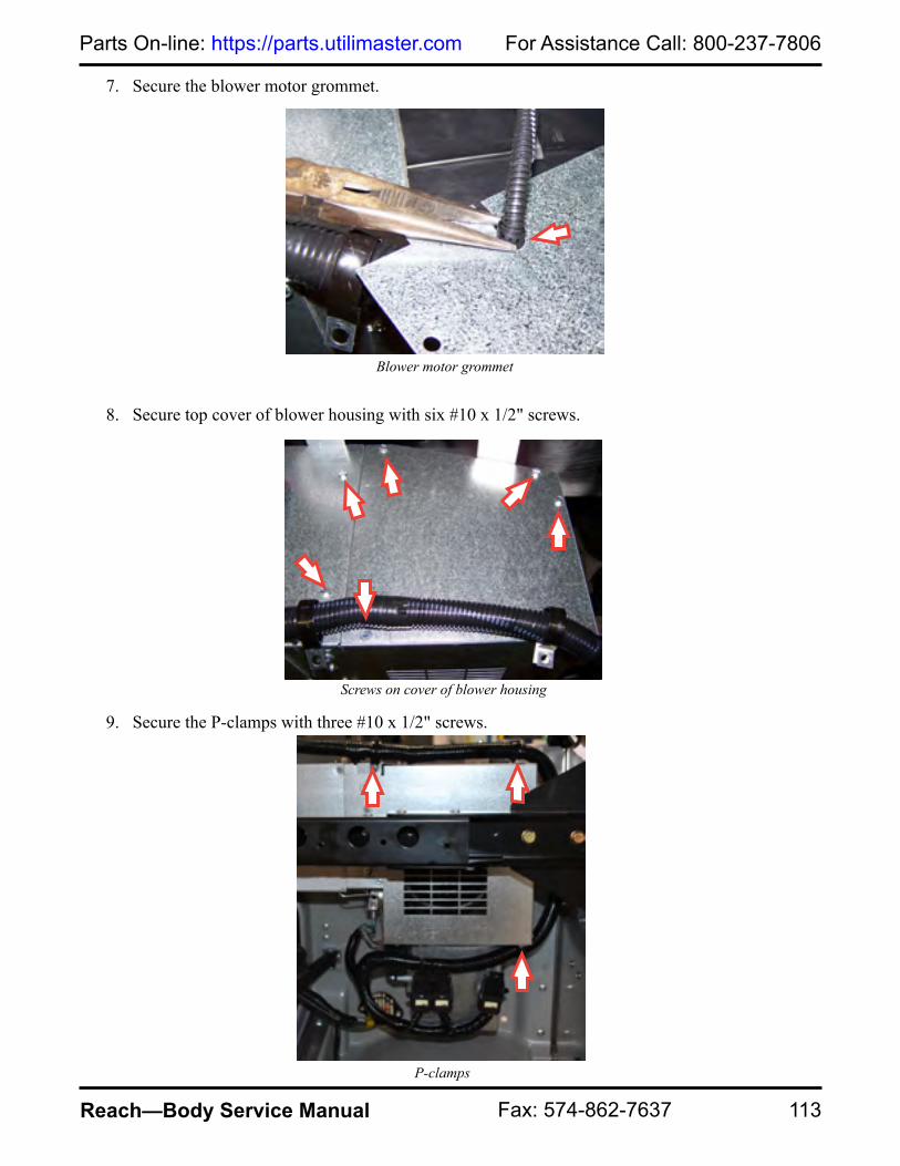
113
For Assistance Call: 800-237-7806Parts On-line: https://parts.utilimaster.com
Reach—Body Service Manual Fax: 574-862-7637
7. Secure the blower motor grommet.
8. Secure top cover of blower housing with six #10 x 1/2" screws.
9. Secure the P-clamps with three #10 x 1/2" screws.
Blower motor grommet
Screws on cover of blower housing
P-clamps

For Assistance Call: 800-237-7806 Visit us at: www.utilimaster.com
114 Reach—Body Service Manual E-mail: [email protected]
10. Slide blower motor support bracket into place and secure one #10 x 1/2" screw above the servo motor.
11. Secure other end of blower motor support bracket with one #10 x 1/2" screw to the right of the relays.
Screw on left-hand side of blower motor support bracket
Screw on right-hand side of blower motor support bracket

115
For Assistance Call: 800-237-7806Parts On-line: https://parts.utilimaster.com
Reach—Body Service Manual Fax: 574-862-7637
12. Secure servo motor with three locknuts and nylon spacers.
13. Secure the thermostat and electric motor wires.
14. Install dash valance panel.
See Install Dash Valance Panel.
Thermostat and servo motor wires

For Assistance Call: 800-237-7806 Visit us at: www.utilimaster.com
116 Reach—Body Service Manual E-mail: [email protected]
CondenserThe condenser is located on the passenger side of the vehicle behind the bumper fascia.
Removal
1. Remove front fascia.
See Remove Front Fascia.2. Drain the air-conditioning system of all refrigerant and disconnect air-conditioning hoses from
the condenser.
3. Remove five M8 screws from the bracket and remove bracket from bumper.
4. Remove 14 blind rivets from condenser.
See Remove Blind Rivet.5. Remove condenser and set aside.
Installation
1. Secure condenser to bracket with 14 blind rivets.
See Install Blind Rivet.2. Secure bracket to bumper with five M8 screws.
3. Torque to 17–21 ft•lbs.
4. Reconnect air-conditioning hoses.
5. Charge air-conditioning system with 1.2 lbs of refrigerant.
6. Start vehicle and check air-conditioning performance.
7. Install front fascia.
See Install Front Fascia.
Condenser
CAUTION: Discard ALL used fasteners and replace with new. If using a fastener that does NOT have preapplied thread lock, apply a medium-grade liquid thread lock.
WARNING: Utilimaster recommends that only a licensed/certified automotive technician services the vehicle's air-conditioning system.

117
For Assistance Call: 800-237-7806Parts On-line: https://parts.utilimaster.com
Reach—Body Service Manual Fax: 574-862-7637
Control ModuleThe control module is located on the left end of the heater close to the fire wall.
NOTE: 1/4" drive ratchet with magnetic sockets will make the process easier.
Removal
NOTE: Keep all hardware for reinstallation. 1. Remove dash valance panel.
See Remove Dash Valance Panel.2. Remove two 8/32" nuts.
3. Pull out on the bottom of control module until module clears studs and gently pull downward.
4. Disconnect wire harness. Inspect wires and connector pins for any defects and set aside.
Nuts on control module
Wire harness

For Assistance Call: 800-237-7806 Visit us at: www.utilimaster.com
118 Reach—Body Service Manual E-mail: [email protected]
Installation
1. Inspect connector pins for defects and replace if necessary.
2. Connect wire harness to control module.
3. Slide control module under lip of bracket.
4. Secure control module with two 8/32" nuts.
5. Turn ignition key to On position and check all functions of heat and air-conditioning system.
6. Install dash valance panel.
See Install Dash Valance Panel.
Dryer
Dryer Removal
NOTE: Keep all hardware for reinstallation. NOTE: The expansion valve must be replaced when replacing the dryer.
1. Drain the air-conditioning system of all refrigerant.
2. Remove grille.
See Remove Grille.3. Remove grille screen.
See Remove Grille Screen.4. Remove air intake from air cleaner assembly.
5. Disconnect air-conditioning hoses from dryer.
Nuts on control module
Air intake
WARNING: Utilimaster recommends that only a licensed/certified automotive technician services the vehicle's air-conditioning system.

119
For Assistance Call: 800-237-7806Parts On-line: https://parts.utilimaster.com
Reach—Body Service Manual Fax: 574-862-7637
6. Remove trinary switch.
See Remove Trinary Switch.7. Remove two screws from dryer mounting bracket and set
aside.
Expansion Valve Removal
NOTE: The hoses do not need to be removed from the manifold.
1. Remove bolt from evaporator manifold and set manifold aside.
2. Remove two bolts from expansion valve and discard valve.
Expansion Valve Installation
1. Lubricate new O-rings with mineral oil and install on expansion valve.
2. Secure expansion valve to evaporator with two bolts.
3. Torque to 30–35 ft•lbs.
4. Secure manifold to expansion valve with bolt.
5. Torque to 10 ft•lbs.
Dryer Installation
1. Install trinary switch.
See Install Trinary Switch.2. Lubricate two new #6 O-rings and attach to dryer.
3. Secure dryer hoses.
4. Torque to 30–35 ft•lbs.
5. Secure dryer with two screws.
6. Torque to 12 ft•lbs.
7. Charge air-conditioning system with 1.2 lbs of refrigerant.
8. Start vehicle and check air-conditioning performance.
9. Install grille screen.
See Install Grille Screen.10. Install grille.
See Install Grille.
Screws on dryer mounting bracket
Evaporator valve bolts
Manifold bolt

For Assistance Call: 800-237-7806 Visit us at: www.utilimaster.com
120 Reach—Body Service Manual E-mail: [email protected]
Trinary Switch
The trinary switch is located on the dryer. The switch has three functions: high pressure cut-out, low pressure cut-out, and condenser fan operation.Removal
1. Disconnect wire harness.
2. Remove switch by turning counterclockwise and set aside.Installation
1. Lubricate rubber seal inside switch with mineral oil.
2. Secure switch by turning clockwise.
3. Connect wire harness.
Switch on dryer

121
For Assistance Call: 800-237-7806Parts On-line: https://parts.utilimaster.com
Reach—Body Service Manual Fax: 574-862-7637
EvaporatorThe evaporator is located on the passenger side of the vehicle.
NOTE: 1/4" drive ratchet with magnetic sockets will make the process easier.
Removal
NOTE: Keep all hardware for reinstallation. 1. Remove heater core.
See Remove Heater Core.2. Drain the air-conditioning system of all refrigerant and disconnect air-conditioning hoses from
the expansion valve located under the hood on the firewall.
3. Remove two #10 x 1/2" screws from thermostat and two #10 x 1/2" screws from evaporator case.
WARNING: Utilimaster recommends that only a licensed/certified automotive technician services the vehicle's air-conditioning system.
Screws on thermostat and evaporator case

For Assistance Call: 800-237-7806 Visit us at: www.utilimaster.com
122 Reach—Body Service Manual E-mail: [email protected]
4. Supporting the evaporator assembly, remove two #10 x 1/2" screws and remove evaporator.
NOTE: Before removing the capillary tube, identify location for proper reinstallation.5. Remove the thermostat capillary tube from coil.
Screws on evaporator assembly
Capillary tube
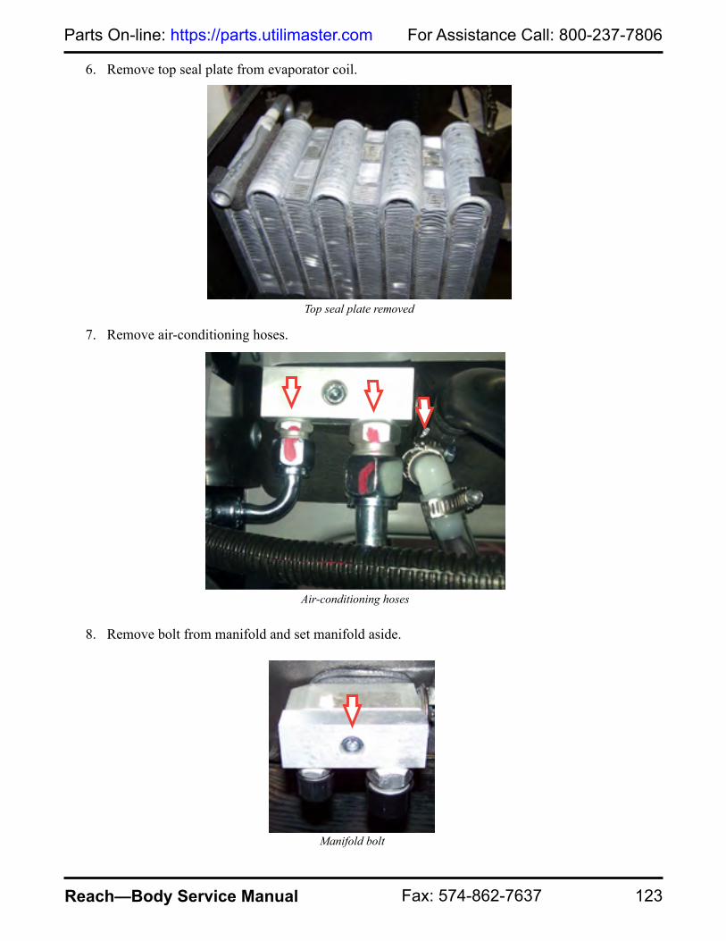
123
For Assistance Call: 800-237-7806Parts On-line: https://parts.utilimaster.com
Reach—Body Service Manual Fax: 574-862-7637
6. Remove top seal plate from evaporator coil.
7. Remove air-conditioning hoses.
8. Remove bolt from manifold and set manifold aside.
Top seal plate removed
Manifold bolt
Air-conditioning hoses

For Assistance Call: 800-237-7806 Visit us at: www.utilimaster.com
124 Reach—Body Service Manual E-mail: [email protected]
9. Remove two bolts from expansion valve and set valve aside.
10. Remove foam seal from inside evaporator assembly at seal plate.
11. Lift seal plate to remove evaporator coil and set aside.
Foam seal
Seal plate
Evaporator valve bolts
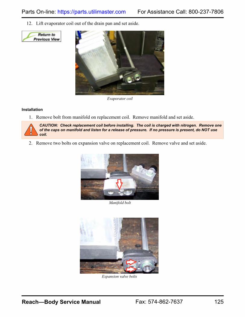
125
For Assistance Call: 800-237-7806Parts On-line: https://parts.utilimaster.com
Reach—Body Service Manual Fax: 574-862-7637
12. Lift evaporator coil out of the drain pan and set aside.
Installation
1. Remove bolt from manifold on replacement coil. Remove manifold and set aside.
2. Remove two bolts on expansion valve on replacement coil. Remove valve and set aside.
Evaporator coil
CAUTION: Check replacement coil before installing. The coil is charged with nitrogen. Remove one of the caps on manifold and listen for a release of pressure. If no pressure is present, do NOT use coil.
Manifold bolt
Expansion valve bolts

For Assistance Call: 800-237-7806 Visit us at: www.utilimaster.com
126 Reach—Body Service Manual E-mail: [email protected]
3. Set coil in drain pan and insert evaporator manifold through opening.
4. Move foam seal to back side of the evaporator case bracket.
5. Secure expansion valve with two bolts.
6. Secure manifold with bolt.
Evaporator manifold
Foam seal
CAUTION: Lubricate o-rings with mineral oil prior to installation.
Expansion valve and manifold

127
For Assistance Call: 800-237-7806Parts On-line: https://parts.utilimaster.com
Reach—Body Service Manual Fax: 574-862-7637
7. Push down on seal bracket until holes in bracket and evaporator case align. Use foam seal packaged with replacement evaporator to seal space between bracket and evaporator manifold.
8. Secure top seal plate to evaporator coil.
Foam seal
Top seal plate

For Assistance Call: 800-237-7806 Visit us at: www.utilimaster.com
128 Reach—Body Service Manual E-mail: [email protected]
9. Install thermostat into coil. Ensure capillary tube is installed in the same location as the original coil.
10. Secure evaporator assembly with two #10 x 1/2" screws.
Capillary tube
Screw location on evaporator assembly
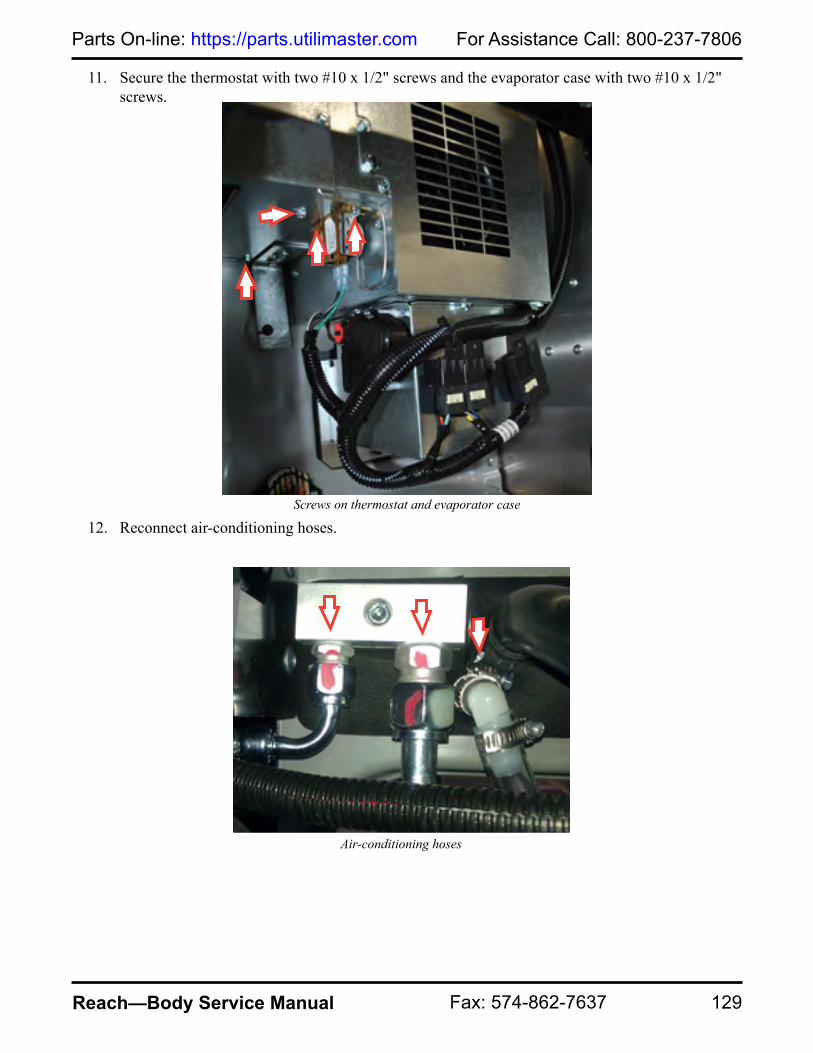
129
For Assistance Call: 800-237-7806Parts On-line: https://parts.utilimaster.com
Reach—Body Service Manual Fax: 574-862-7637
11. Secure the thermostat with two #10 x 1/2" screws and the evaporator case with two #10 x 1/2" screws.
12. Reconnect air-conditioning hoses.
Air-conditioning hoses
Screws on thermostat and evaporator case

For Assistance Call: 800-237-7806 Visit us at: www.utilimaster.com
130 Reach—Body Service Manual E-mail: [email protected]
13. Install heater core.
See Install Heater Core.14. Charge air-conditioning system with 1.2 lbs of refrigerant.
15. Start vehicle and check air-conditioning performance.
Heater CoreNOTE: 5/16" drive ratchet with magnetic sockets will make the process easier.
Removal
NOTE: Keep all hardware for reinstallation. 1. Under the hood on the passenger side, clamp heater and drain hoses and remove from evaporator
assembly.
2. Remove two #10 x 1/2" screws through the access holes in the foam seal.
WARNING: Utilimaster recommends that only a licensed/certified automotive technician services the vehicle's air-conditioning system.
Heater hoses
Screw location behind foam seal
CAUTION: Evacuate the air in the coolant system anytime it has had a coolant fluid loss.

131
For Assistance Call: 800-237-7806Parts On-line: https://parts.utilimaster.com
Reach—Body Service Manual Fax: 574-862-7637
3. Remove dash valance panel.
See Remove Dash Valance Panel. 4. Remove six #10 x 1/2" screws on evaporator case.
5. Remove coil (core) assembly by pulling towards the rear of the vehicle and angling the assembly down.
Screws on evaporator case
Heater core assembly

For Assistance Call: 800-237-7806 Visit us at: www.utilimaster.com
132 Reach—Body Service Manual E-mail: [email protected]
6. Remove by raising heater core out of bracket.
Installation
1. Place heater core assembly into the case with bracket on inside of drain pan.
Heater core
Heater core

133
For Assistance Call: 800-237-7806Parts On-line: https://parts.utilimaster.com
Reach—Body Service Manual Fax: 574-862-7637
2. Secure heater assembly to evaporator case with six #10 x 1/2" screws.
3. Secure heater with two #10 x 1/2" screws through access holes in foam seal.
Screws on evaporator case
Screw location behind foam seal

For Assistance Call: 800-237-7806 Visit us at: www.utilimaster.com
134 Reach—Body Service Manual E-mail: [email protected]
4. Reconnect heater and drain hoses to evaporator assembly located under the hood and unclamp hoses.
5. Replace engine coolant that has been drained or lost.
6. Check that system is operating properly.
7. Install dash valance panel.
See Install Dash Valance Panel.
Heater ValveThe heater valve is located under the hood mounted to the cowl in the center of the vehicle.
Heater hoses
Location of heater valve

135
For Assistance Call: 800-237-7806Parts On-line: https://parts.utilimaster.com
Reach—Body Service Manual Fax: 574-862-7637
Removal
NOTE: Keep all hardware for reinstallation. 1. Remove air intake from air cleaner assembly.
2. Clamp heater hoses on both sides of the valve.
3. Disconnect wire harness from the valve.
4. Remove two bolts and nuts from the driver's side of the heater valve.
5. Loosen heater hose clamps and remove heater hoses from valve.
6. Remove two bolts and nuts from passenger's side of the heater valve.
7. Remove heater valve and set aside.
CAUTION: Evacuate the air in the coolant system anytime it has had a coolant fluid loss.
Air intake
Wire harness

For Assistance Call: 800-237-7806 Visit us at: www.utilimaster.com
136 Reach—Body Service Manual E-mail: [email protected]
Installation
1. Secure heater hoses to valve with directional arrow pointing toward passenger's side.
2. Torque clamps to 17–21 ft•lbs.
3. Connect wire harness to valve.
4. Secure water valve with four bolts and nuts.
5. Remove clamps from heater hoses.
6. Replace antifreeze that has been drained or lost.
7. Vacuum fill the system.
8. Start engine and check that the system is operating properly.
Directional arrow points towards passenger's side.
Wire harness

137
For Assistance Call: 800-237-7806Parts On-line: https://parts.utilimaster.com
Reach—Body Service Manual Fax: 574-862-7637
HosesThe hoses for the heating and air conditioning unit are located under the hood.
Dryer
Drain hoseCompressor
Water control valve
Engine

For Assistance Call: 800-237-7806 Visit us at: www.utilimaster.com
138 Reach—Body Service Manual E-mail: [email protected]
Mode (Servo) MotorThere are four mode (servo) motors on the heating and air-conditioning unit. The motors operate the recirculation, floor, dash, and defrost doors. All motors are serviced the same.
NOTE: To access the floor, dash, or defrost servo motors, remove the dash valance panel.See Remove Dash Valance Panel.
NOTE: To access the recirculation servo motor, remove the washer bottle panel.See Remove Washer Bottle Panel.
Removal
NOTE: Keep all hardware for reinstallation. 1. Remove the wire harness by pressing the tab on the top of the servo motor.
2. Remove three 8/32" locknuts.
3. Pull motor off mounting studs and set aside.
Servo motor wire harness Locknuts on servo motor

139
For Assistance Call: 800-237-7806Parts On-line: https://parts.utilimaster.com
Reach—Body Service Manual Fax: 574-862-7637
Installation
1. Align shaft on door with socket on motor. Push down carefully until motor bottoms out on nylon spacers.
2. Secure motor with three 8/32" locknuts.
3. Reconnect wire harness to servo motor.
4. Turn ignition key to on position and check motor operation.
NOTE: Install dash valance panel if floor, dash, or defrost servo motors were accessed.See Install Dash Valance Panel.
NOTE: Install washer bottle panel if recirculation servo motor was accessed.See Install Washer Bottle Panel.
Locknuts on servo motor
Servo motor wire harness

For Assistance Call: 800-237-7806 Visit us at: www.utilimaster.com
140 Reach—Body Service Manual E-mail: [email protected]
ResistorTo access the blower resistor the blower motor must first be removed. The blower resistor is located behind an access panel on the blower housing.
Removal
NOTE: Keep all hardware for reinstallation. 1. Remove blower motor.
See Remove Blower Motor.2. Remove two #10 x 1/2" screws located between the two bolts holding blower housing to
evaporator case.
3. Pull blower resistor through opening and remove two #10 x 1/2" screws.
4. Identify colors of wires and locations. Disconnect wires.
5. Remove resistor and set aside.
Screws on blower housing
Blower resistor

141
For Assistance Call: 800-237-7806Parts On-line: https://parts.utilimaster.com
Reach—Body Service Manual Fax: 574-862-7637
Installation
1. Use a pair of pliers to gently squeeze the female spade terminals for a more secure connection.
2. Secure resistor with two #10 x 1/2" screws and reconnect wires in the order removed.
Spade terminals
Blower resistor

For Assistance Call: 800-237-7806 Visit us at: www.utilimaster.com
142 Reach—Body Service Manual E-mail: [email protected]
3. Secure the blower housing to the evaporator case with two #10 x 1/2" screws.
4. Install blower motor.
See Install Blower Motor.
ThermostatThe thermostat is located on the passenger side of the vehicle left of the blower motor. Remove the washer bottle panel to access.
See Remove Washer Bottle Panel.
Thermostat
Screws on blower housing

143
For Assistance Call: 800-237-7806Parts On-line: https://parts.utilimaster.com
Reach—Body Service Manual Fax: 574-862-7637
HoodOpen
1. Pull interior hood release.
2. Pull secondary latch to the left to release.
3. Raise hood and support with prop rod.
Adjustment
Hinges
4. Open hood.
See Open Hood.5. Loosen two M8 bolts on hood hinge bracket.
6. Adjust hood.
7. Secure prop rod into rest position and close hood.
8. Check alignment and adjust if necessary.
9. Torque to 17–21 ft•lbs. Hood hinge bracket
Hood release Secondary latch
WARNING: Always support the hood to keep it from falling.
CAUTION: Discard ALL used fasteners and replace with new. If using a fastener that does NOT have preapplied thread lock, apply a medium-grade liquid thread lock.

For Assistance Call: 800-237-7806 Visit us at: www.utilimaster.com
144 Reach—Body Service Manual E-mail: [email protected]
Overslam Bumpers
1. Loosen jam nut to adjust hood bumper.
2. Turn bumper to raise or lower.
3. Close hood to check adjustment.
4. Repeat if necessary.
5. Tighten jam nut.
6. Repeat on opposite side if necessary.
Removal
1. Open hood.
See Open Hood.2. Remove hood hinge shoulder screw and nut.
3. Repeat on opposite side.
4. Set hood aside.
Hood hinge
Jam nut
CAUTION: Discard ALL used fasteners and replace with new. If using a fastener that does NOT have preapplied thread lock, apply a medium-grade liquid thread lock.

145
For Assistance Call: 800-237-7806Parts On-line: https://parts.utilimaster.com
Reach—Body Service Manual Fax: 574-862-7637
Installation
1. Secure hood hinge and hood hinge bracket with shoulder screw and two nylon washers.
2. Secure nut onto shoulder screw.
3. Repeat on opposite side.
4. Adjust if necessary.
See Adjust Hood.5. Torque to 17–21 ft•lbs.
Disassembly1. Remove hood.
See Remove Hood.2. Remove four M8 bolts at hood
hinges.
3. Set hood hinges aside.
Hood hinge
NYLON WASHER
NYLON WASHER
HOOD HINGE
HOOD HINGE BRACKET
SHOULDER SCREW
Shoulder screw installation
CAUTION: Discard ALL used fasteners and replace with new. If using a fastener that does NOT have preapplied thread lock, apply a medium-grade liquid thread lock.

For Assistance Call: 800-237-7806 Visit us at: www.utilimaster.com
146 Reach—Body Service Manual E-mail: [email protected]
4. Remove four M8 bolts in hood hinge brackets.
5. Set hood hinge brackets aside.
6. Remove two M6 bolts in hood catch.
7. Set hood catch aside.
Assembly
1. Secure hood catch with two M6 bolts.
2. Torque to 7–8 ft•lbs.
3. Secure hood hinge brackets with M8 bolts.
4. Torque to 17–21 ft•lbs.
5. Secure hood hinges with M8 bolts.
6. Close hood and check latch alignment.
7. Adjust if necessary.
See Adjust Hood.8. Install Hood.
See Install Hood.
Hood hinge bracket
Hood catch
CAUTION: Discard ALL used fasteners and replace with new. If using a fastener that does NOT have preapplied thread lock, apply a medium-grade liquid thread lock.

147
For Assistance Call: 800-237-7806Parts On-line: https://parts.utilimaster.com
Reach—Body Service Manual Fax: 574-862-7637
Hood LatchRemoval
1. Open hood.
See Open Hood.2. Remove grille.
See Remove Grille.3. Remove two M6 bolts through access holes.
NOTE: For installation of latch, note location and quantity of washers to ensure proper alignment for installation.
4. Remove latch from mount.
5. Disconnect cable from latch release.
6. Remove cable from guide.
7. Set hood latch aside.
Latch release Cable guide
M6 BOLT
ACCESS HOLE WELD NUT
M6 WASHERS
CAUTION: Discard ALL used fasteners and replace with new. If using a fastener that does NOT have preapplied thread lock, apply a medium-grade liquid thread lock.

For Assistance Call: 800-237-7806 Visit us at: www.utilimaster.com
148 Reach—Body Service Manual E-mail: [email protected]
Installation
1. Secure hood release cable.
2. Secure latch into mount with M6 bolts and washers through access holes.
NOTE: More than one washer may be needed in order for catch to properly secure latch.
3. Check alignment and adjust if necessary.
4. Torque to 7–8 ft•lbs.
5. Install grille.
See Install Grille.
Latch releaseCable guide
M6 BOLT
ACCESS HOLE WELD NUT
M6 WASHERS
CAUTION: Discard ALL used fasteners and replace with new. If using a fastener that does NOT have preapplied thread lock, apply a medium-grade liquid thread lock.

149
For Assistance Call: 800-237-7806Parts On-line: https://parts.utilimaster.com
Reach—Body Service Manual Fax: 574-862-7637
Hood CableRemoval
1. Open hood.
See Open Hood.2. Remove grille.
See Remove Grille.3. Remove hood latch.
See Remove Hood Latch.4. Remove cable from securement clamps.
5. Remove hood release handle, jam nut, and washer.
6. Pull cable through backside of mounting bracket.
7. Pull cable through cowl panel.
8. Set hood release cable aside.
Hood release handle
Mounting bracket
CAUTION: Discard ALL used fasteners and replace with new. If using a fastener that does NOT have preapplied thread lock, apply a medium-grade liquid thread lock.

For Assistance Call: 800-237-7806 Visit us at: www.utilimaster.com
150 Reach—Body Service Manual E-mail: [email protected]
Installation
1. Push cable through rubber grommet in cowl panel.
2. Push cable through backside of mounting bracket.
3. Secure washer, jam nut, and hood release handle onto cable.
4. Tighten jam nuts on both sides of mounting bracket.
5. Install hood latch.
See Install Hood Latch.6. Secure cable with clips under hood.
7. Install grille.
See Install Grille.
Hood release handle
Mounting bracket
CAUTION: Discard ALL used fasteners and replace with new. If using a fastener that does NOT have preapplied thread lock, apply a medium-grade liquid thread lock.

151
For Assistance Call: 800-237-7806Parts On-line: https://parts.utilimaster.com
Reach—Body Service Manual Fax: 574-862-7637
LightsGrommet-mountedGrommet-mounted lights are used in a variety of areas including: back-up lights, rear turn lights, cab and cargo dome lights, and brake lights. Bullet lights, mini-marker lights, and 4" round lights are all grommet-mounted lights.
Removal
NOTE: To remove the 4" round light, insert a flat-blade screwdriver between the light and rubber grommet to separate the light from the grommet. To remove all other lights, push light out through front of grommet.NOTE: To ease in the removal and installation process, lightly spray the grommet and light with soapy water.
1. Turn off ignition and all lights.
2. Remove light from grommet.
3. Disconnect wire harness from light and set aside.
4. Remove and replace grommet if necessary.
Installation
1. Install grommet.
2. Connect wire harness to light.
3. Push light carefully through the front of the grommet.
HeadlightsAdjustment
NOTE: If no headlight-aiming tool is available, perform steps 8–11 as a temporary solution until a properly calibrated headlight-aiming tool can be obtained.
1. Turn off ignition.
2. Remove any load from the vehicle.
3. The vehicle should have approximately a half tank of fuel.
4. Check that the tires are properly inflated to the tire manufacturer's recommended inflation.
5. Check headlights to ensure they are clean.
6. Park on level surface.
CAUTION: The slit on the rear of the grommet must be pointed down to allow water to drain.
Place screwdriver between light and grommet.
Marker light
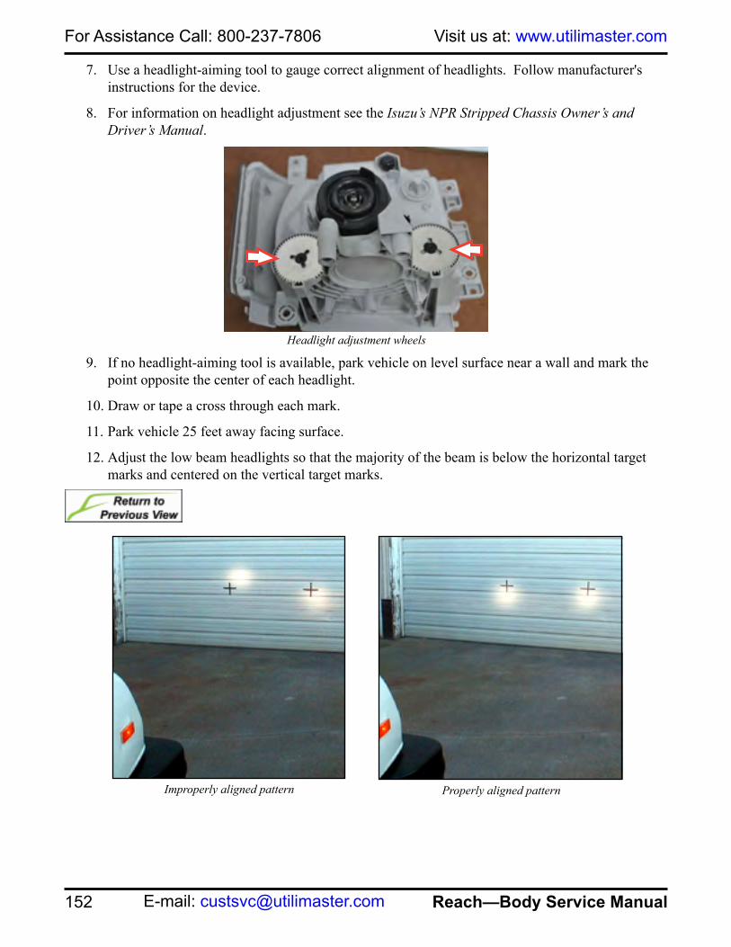
For Assistance Call: 800-237-7806 Visit us at: www.utilimaster.com
152 Reach—Body Service Manual E-mail: [email protected]
7. Use a headlight-aiming tool to gauge correct alignment of headlights. Follow manufacturer's instructions for the device.
8. For information on headlight adjustment see the Isuzu’s NPR Stripped Chassis Owner’s and Driver’s Manual.
9. If no headlight-aiming tool is available, park vehicle on level surface near a wall and mark the point opposite the center of each headlight.
10. Draw or tape a cross through each mark.
11. Park vehicle 25 feet away facing surface.
12. Adjust the low beam headlights so that the majority of the beam is below the horizontal target marks and centered on the vertical target marks.
Improperly aligned pattern Properly aligned pattern
Headlight adjustment wheels

153
For Assistance Call: 800-237-7806Parts On-line: https://parts.utilimaster.com
Reach—Body Service Manual Fax: 574-862-7637
Removal
1. Turn off ignition and all lights.
2. Remove grille.
See Remove Grille.3. Remove two M6 screws in headlight bezel.
4. Remove two M4 screws in headlight bezel and set bezel aside.
5. Disconnect wire harness.
6. Remove four M8 bolts and set headlight aside.
Installation
1. Turn off ignition and all lights.
2. Secure headlight with four M8 bolts.
3. Torque to 65–75 ft•lbs.
4. Connect to wire harness.
5. Secure headlight bezel with two M6 screws.
6. Torque to 7–8 ft•lbs.
7. Secure headlight bezel with two M4 screws.
8. Install grille.
See Install Grille.9. Adjust headlight.
See Adjust Headlight.
Bolt locations
CAUTION: Discard ALL used fasteners and replace with new. If using a fastener that does NOT have preapplied thread lock, apply a medium-grade liquid thread lock.
Screw location on headlight bezel

For Assistance Call: 800-237-7806 Visit us at: www.utilimaster.com
154 Reach—Body Service Manual E-mail: [email protected]
Headlight BulbRemoval
1. Turn off ignition and all lights.
2. Disconnect wire harness.
3. Remove rubber cover by pulling on the tabs.
4. Release spring securing headlight bulb.
5. Remove bulb from socket and discard.Installation
1. Turn off ignition and all lights.
1. Place bulb in headlight housing.
2. Secure spring over bulb.
3. Push rubber cover onto headlight.
4. Connect wire harness.
CAUTION: When installing the headlight bulb, do NOT touch the bulb with fingers. Oils from fingers can cause the bulb to blow out.
WARNING: The headlight bulb may be very hot. Use caution when removing.
Tabs located on rubber cover
Spring securing headlight bulb
Wire harness

155
For Assistance Call: 800-237-7806Parts On-line: https://parts.utilimaster.com
Reach—Body Service Manual Fax: 574-862-7637
Parking Light Removal
1. Turn off ignition and all lights.
2. Turn the socket counterclockwise.
3. Pull parking light out of socket and discard.Installation
1. Turn off ignition and all lights.
2. Secure new bulb into socket and place into headlight housing.
3. Secure the socket by turning clockwise.
Switches, Convenience Panel
RemovalLight switches are used in different locations throughout the vehicle. The removal and installation process is typically the same for all switches.
1. Turn off ignition and all lights.
2. Remove four #8 Phillips head screws from tray and set tray aside.
3. Disconnect switch from wire harness.
4. Squeeze tab on back of switch to remove through front of dash panel.
5. To remove actuator, lift up on one end of the actuator until it releases from the switch.
Installation
1. Turn off ignition and all lights.
2. To install actuator, line up pin on actuator with hole on switch and press together.
3. Push switch through front of dash panel.
4. Connect switch to wire harness.
5. Secure tray with four #8 Phillips head screws.
6. Torque to 23–27 in•lbs.
Parking light socket
CAUTION: Discard ALL used fasteners and replace with new. If using a fastener that does NOT have preapplied thread lock, apply a medium-grade liquid thread lock.
Light switches
Screw location on tray
Switch and actuator

For Assistance Call: 800-237-7806 Visit us at: www.utilimaster.com
156 Reach—Body Service Manual E-mail: [email protected]
Turn, Front FasciaRemoval
1. Turn off ignition and all lights.
2. Remove front fascia.
See Remove Front Fascia.3. Unplug the wire harness.
4. Remove three Phillips head screws from light and set aside.
Installation
1. Turn off ignition and all lights.
2. Secure with three Phillips head screws
3. Plug in wire harness.
4. Install front fascia.
See Install Front Fascia.
Screw locationsFront turn signals

157
For Assistance Call: 800-237-7806Parts On-line: https://parts.utilimaster.com
Reach—Body Service Manual Fax: 574-862-7637
MirrorsAdjustment
To receive maximum benefit from the outside mirrors, adjust the driver’s side mirror so you can see just a small amount of the side of the vehicle. Have someone assist you by adjusting the passenger’s side and driver’s side mirrors while sitting back in the driver’s seat. Some exterior mirrors are convex. A convex mirror’s surface is curved to increase the visible area, but use these mirrors with care, especially when changing lanes and backing up.
Removal
NOTE: On driver’s side, remove front quarter before removing mirror arm.See Remove Front Fender.
NOTE: On passenger’s side, remove A-pillar trim before removing mirror arm.See Remove A-Pillar Trim.
1. Remove four Phillips head screws from mirror access cap and set cap aside.
2. Loosen four 3/16" hex head screws that hold the mirror head on to the mirror arm.
3. Set mirror head aside.
CAUTION: Discard ALL used fasteners and replace with new. If using a fastener that does NOT have preapplied thread lock, apply a medium-grade liquid thread lock.
WARNING: To prevent breakage and possible injury, do NOT push directly on the glass. Push on the mirror frames only.
Mirror access cap screw location
WARNING: Objects seen in convex mirrors are closer than they may appear.

For Assistance Call: 800-237-7806 Visit us at: www.utilimaster.com
158 Reach—Body Service Manual E-mail: [email protected]
4. Remove eight rivets from mirror arm.
See Remove Blind Rivets.5. Set mirror arm aside.
Installation
6. Secure mirror arm with eight rivets.
See Install Blind Rivets.7. Secure mirror head with four 3/16" hex head screws.
8. Torque to 4–5 in•lbs.
9. Secure mirror access cap with four Phillips head screws.
10. Torque to 4–5 in•lbs.
NOTE: On driver’s side, install front fender after installing mirror arm.See Install Front Fender.
NOTE: On passenger’s side, install A-pillar trim after installing mirror arm.See Install A-Pillar Trim.
CAUTION: Discard ALL used fasteners and replace with new. If using a fastener that does NOT have preapplied thread lock, apply a medium-grade liquid thread lock.
Driver’s side arm Magna-lok locations
Passenger’s side arm Magna-lok locations

159
For Assistance Call: 800-237-7806Parts On-line: https://parts.utilimaster.com
Reach—Body Service Manual Fax: 574-862-7637
Rear Vision SystemCameraRemoval
1. Remove rear header cladding.
See Remove Rear Header Cladding.2. Disconnect camera cable.
3. Hold the rear of the camera and turn the lens counterclockwise.
4. Remove cable and camera from the rear of the header and set aside.
Installation
1. Clean camera lens if necessary.
2. Place the camera in the back side of the header with the flat side of the camera at 12 o'clock position.
3. Hold the back side of the camera and turn the lens clockwise.
4. Connect camera cables.
5. Install rear header cladding.
See Install Rear Header Cladding.
MonitorRemoval
1. Remove overhead panel.
See Remove Overhead Panel.2. Disconnect monitor cable from the signal splitter.
3. Remove monitor by turning handle on mounting bracket arm and set monitor aside.
Installation
1. Secure monitor to mounting bracket arm by turning handle.
2. Secure cable to signal splitter.
3. Install overhead panel.
See Install Overhead Panel.
Flat side of camera
Handle on mounting bracket arm
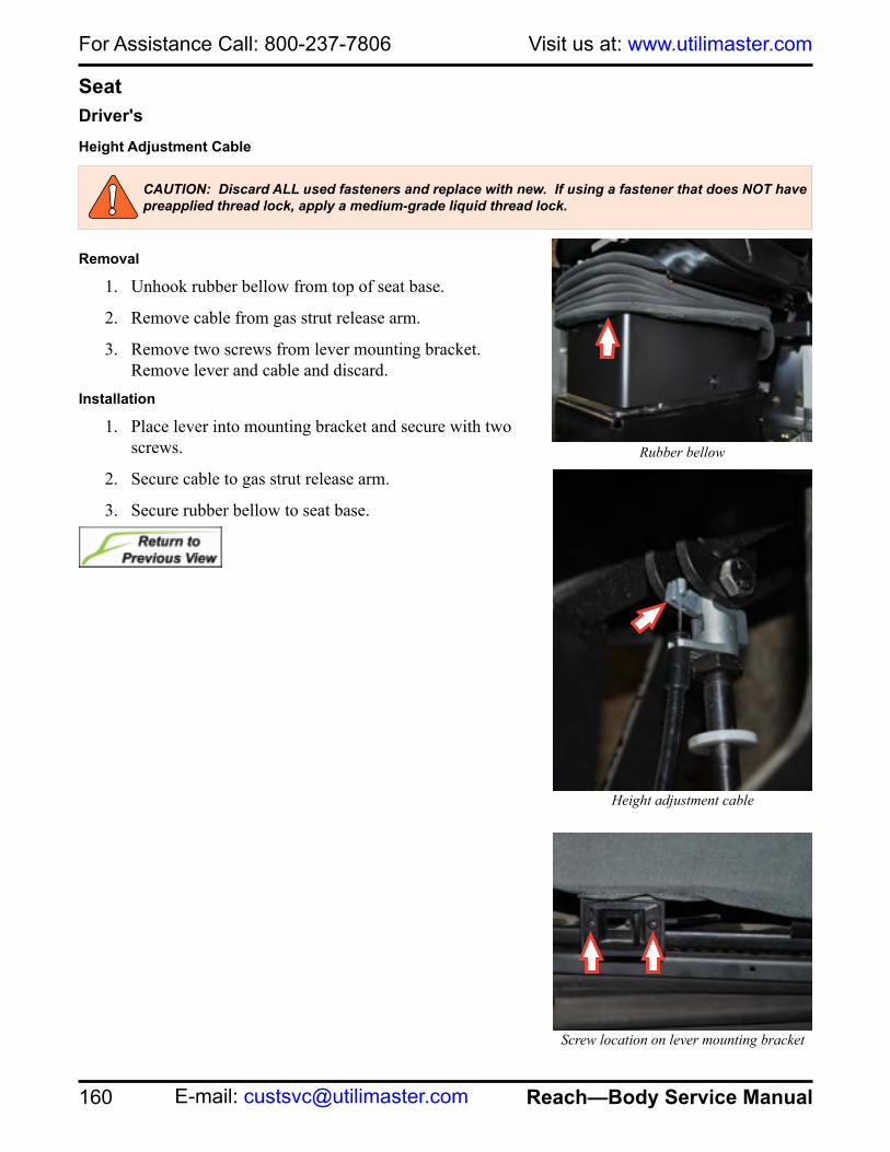
For Assistance Call: 800-237-7806 Visit us at: www.utilimaster.com
160 Reach—Body Service Manual E-mail: [email protected]
SeatDriver'sHeight Adjustment Cable
Removal
1. Unhook rubber bellow from top of seat base.
2. Remove cable from gas strut release arm.
3. Remove two screws from lever mounting bracket. Remove lever and cable and discard.
Installation
1. Place lever into mounting bracket and secure with two screws.
2. Secure cable to gas strut release arm.
3. Secure rubber bellow to seat base.
CAUTION: Discard ALL used fasteners and replace with new. If using a fastener that does NOT have preapplied thread lock, apply a medium-grade liquid thread lock.
Height adjustment cable
Screw location on lever mounting bracket
Rubber bellow

161
For Assistance Call: 800-237-7806Parts On-line: https://parts.utilimaster.com
Reach—Body Service Manual Fax: 574-862-7637
Jump SeatSpringRemoval
1. Remove the nut, washer, and bolt from the jump seat. Keep for reinstallation.
2. Remove spring from clips and discard.Installation
1. Secure spring to clips.
2. Secure spring to seat with bolt, washer and nut.
Bolt location on jump seat
Clip location

For Assistance Call: 800-237-7806 Visit us at: www.utilimaster.com
162 Reach—Body Service Manual E-mail: [email protected]
Seat BeltInspection
Inspect the belt daily. Check for cuts, frays, and loose parts. Damaged parts must be replaced immediately. Do not disassemble or modify the seat belt assembly.A seat belt system should be replaced immediately if it shows any problems, such as:
• Cuts, fraying, abrasion, or other wear to the seat belt webbing.• Significant discoloration due to ultraviolet exposure.• Significant dirt.• Damage to the buckle, latch plate, retractor, or hardware.
WARNING: If there is any damage to the belt or retractor, always replace the entire assembly.
Web cut, frayed, orworn at D-Loop guide
Web cut, frayed, orworn at latch area
Buckle crackedor broken
Damaged strap
Signs of wear

163
For Assistance Call: 800-237-7806Parts On-line: https://parts.utilimaster.com
Reach—Body Service Manual Fax: 574-862-7637
Removal
NOTE: Refer to the instructions provided with the seat belt.1. Remove 7/16-20 nut and bolt from buckle and discard buckle.
2. Remove cover from retractor and remove 7/16-20 nut and bolt.
3. Remove 7/16-20 nut and bolt from seat belt on the side of the seat.
4. Remove 7/16-20 nut and bolt from seat belt on the B-pillar and discard seat belt.
Installation
1. Secure seat belt at B-pillar with 7/16-20 bolt, washer and nut.
2. Secure seat belt to the side of the seat with 7/16-20 bolt, washer and nut.
3. Secure retractor with 7/16-20 bolt.
4. Secure buckle on the side of the seat with 7/16-20 bolt and nut.
5. Torque to 39–45 ft•lbs.
WARNING: When a seat belt is replaced, the entire assembly must be replaced.Use the new mounting hardware furnished with the replacement belt. Do NOT use old hardware when installing replacement seat belts.The retractor must be located in the proper position on the bracket for the seat belt web to release and function properly.
CAUTION: Discard ALL used fasteners and replace with new. If using a fastener that does NOT have preapplied thread lock, apply a medium-grade liquid thread lock.
Bolt location on buckle
Retractor cover Bolt location on retractor
Bolt location on B-pillar

For Assistance Call: 800-237-7806 Visit us at: www.utilimaster.com
164 Reach—Body Service Manual E-mail: [email protected]
StereoRemoval
1. Remove tray panel.
See Remove Tray Panel.2. Disconnect wiring harness from radio.
3. Remove four #8 Phillips head screws from convenience panel.
4. Tilt convenience panel forward, remove radio from retaining clips, and set radio aside.
Installation1. Secure radio with retaining clips.
2. Secure convenience panel to dash with four #8 Phillips head screws.
3. Torque to 23–27 in•lb.
4. Connect wiring harness to radio.
5. Install tray panel.
See Install Tray Panel.
CAUTION: Discard ALL used fasteners and replace with new. If using a fastener that does NOT have preapplied thread lock, apply a medium-grade liquid thread lock.
Convenience panel
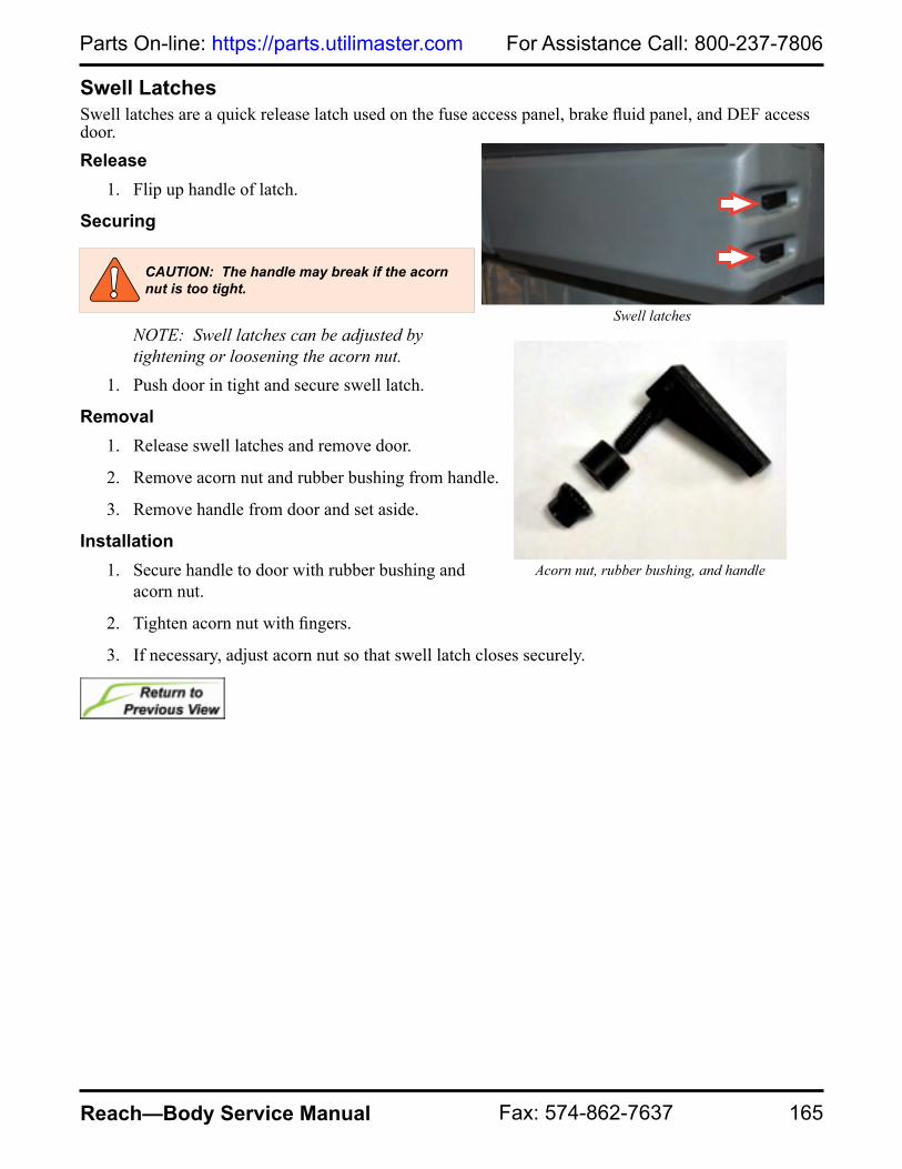
165
For Assistance Call: 800-237-7806Parts On-line: https://parts.utilimaster.com
Reach—Body Service Manual Fax: 574-862-7637
Swell LatchesSwell latches are a quick release latch used on the fuse access panel, brake fluid panel, and DEF access door. Release
1. Flip up handle of latch.
Securing
NOTE: Swell latches can be adjusted by tightening or loosening the acorn nut.
1. Push door in tight and secure swell latch.
Removal1. Release swell latches and remove door.
2. Remove acorn nut and rubber bushing from handle.
3. Remove handle from door and set aside.
Installation1. Secure handle to door with rubber bushing and
acorn nut.
2. Tighten acorn nut with fingers.
3. If necessary, adjust acorn nut so that swell latch closes securely.
Swell latches
Acorn nut, rubber bushing, and handle
CAUTION: The handle may break if the acorn nut is too tight.
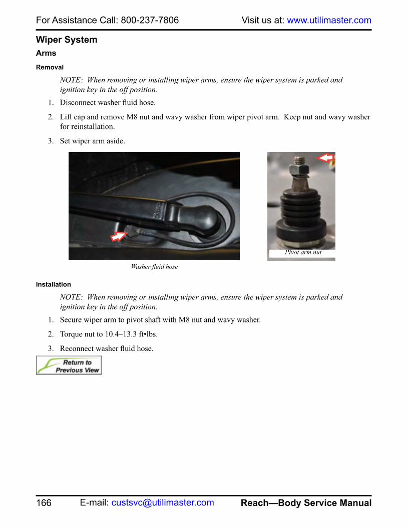
For Assistance Call: 800-237-7806 Visit us at: www.utilimaster.com
166 Reach—Body Service Manual E-mail: [email protected]
Wiper SystemArmsRemoval
NOTE: When removing or installing wiper arms, ensure the wiper system is parked and ignition key in the off position.
1. Disconnect washer fluid hose.
2. Lift cap and remove M8 nut and wavy washer from wiper pivot arm. Keep nut and wavy washer for reinstallation.
3. Set wiper arm aside.
Installation
NOTE: When removing or installing wiper arms, ensure the wiper system is parked and ignition key in the off position.
1. Secure wiper arm to pivot shaft with M8 nut and wavy washer.
2. Torque nut to 10.4–13.3 ft•lbs.
3. Reconnect washer fluid hose.
Washer fluid hose
Pivot arm nut
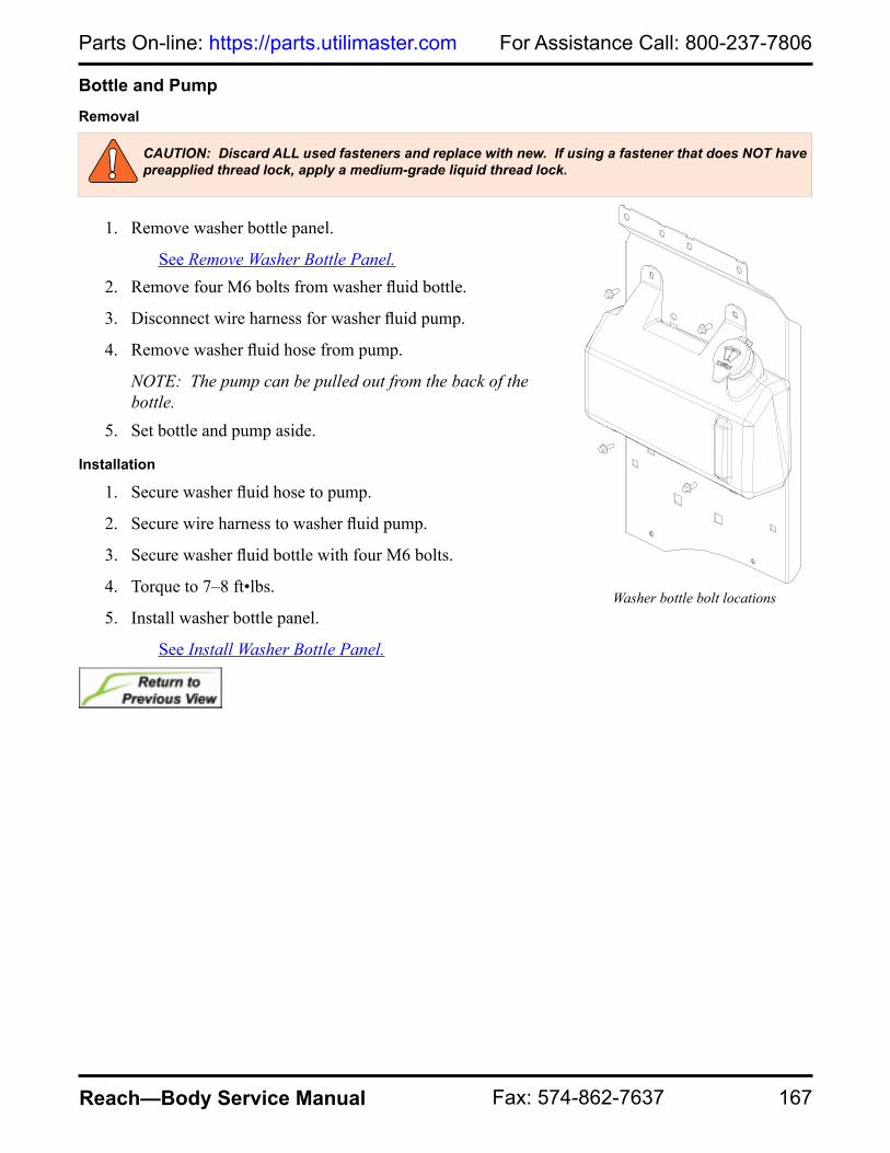
167
For Assistance Call: 800-237-7806Parts On-line: https://parts.utilimaster.com
Reach—Body Service Manual Fax: 574-862-7637
Bottle and PumpRemoval
1. Remove washer bottle panel.
See Remove Washer Bottle Panel.2. Remove four M6 bolts from washer fluid bottle.
3. Disconnect wire harness for washer fluid pump.
4. Remove washer fluid hose from pump.
NOTE: The pump can be pulled out from the back of the bottle.
5. Set bottle and pump aside.
Installation
1. Secure washer fluid hose to pump.
2. Secure wire harness to washer fluid pump.
3. Secure washer fluid bottle with four M6 bolts.
4. Torque to 7–8 ft•lbs.
5. Install washer bottle panel.
See Install Washer Bottle Panel.
CAUTION: Discard ALL used fasteners and replace with new. If using a fastener that does NOT have preapplied thread lock, apply a medium-grade liquid thread lock.
Washer bottle bolt locations

For Assistance Call: 800-237-7806 Visit us at: www.utilimaster.com
168 Reach—Body Service Manual E-mail: [email protected]
Linkage AssemblyRemoval
1. Remove wiper arms.
See Remove Wiper Arms.2. Remove rubber caps from pivot arms.
3. Remove M20 nuts and washers from pivot arms. Keep for reinstallation.
4. Remove four M6 bolts from wiper mount brackets.
5. Remove two bolts and nuts from brace mounting studs.
6. Move linkage assembly as far over to the passenger’s side, then pull out through the driver’s side. Set linkage assembly aside.
CAUTION: Discard ALL used fasteners and replace with new. If using a fastener that does NOT have preapplied thread lock, apply a medium-grade liquid thread lock.
M20 NUT
SPACER
WASHERSCAP
M8 NUT
Pivot arm
Nut locations on brace mounting studs
Bolt location on wiper mount brackets

169
For Assistance Call: 800-237-7806Parts On-line: https://parts.utilimaster.com
Reach—Body Service Manual Fax: 574-862-7637
Installation
1. Install linkage assembly with spacers and washers.
2. Secure brace mounting studs with two bolts and nuts.
3. Secure linkage assembly to wiper mount brackets with four M6 bolts.
4. Torque to 7–8 ft•lbs.
5. Secure pivot arm with washers and M20 nuts.
6. Torque 13–16 ft•lbs.
7. Secure rubber caps to pivot arms.
8. Install wiper arms.
See Install Wiper Arms.
CAUTION: Discard ALL used fasteners and replace with new. If using a fastener that does NOT have preapplied thread lock, apply a medium-grade liquid thread lock.
M20 NUT
SPACER
WASHERSCAP
M8 NUT
Pivot arm
Nut locations on brace mounting studs
Bolt location on wiper mount brackets

For Assistance Call: 800-237-7806 Visit us at: www.utilimaster.com
170 Reach—Body Service Manual E-mail: [email protected]
MotorRemoval
1. Remove linkage assembly.
See Remove Linkage Assembly.2. Remove the M8 nut to remove motor from linkage pivot shaft. Keep nut for reinstallation.
3. Remove the three screws to remove motor from mounting plate. Keep screws for reinstallation.
4. Set motor aside.
Installation
1. Secure the motor to the mounting plate with three screws.
2. Secure the linkage pivot shaft to the motor with nut.
3. Torque to 17–21 ft•lbs.
4. Install the linkage assembly.
See Install Linkage Assembly.
Bolt location on pivot shaft Screw locations on mounting plate

171
For Assistance Call: 800-237-7806Parts On-line: https://parts.utilimaster.com
Reach—Body Service Manual Fax: 574-862-7637
Tools, Fasteners, and Adhesive TapesRecommend Tools
Below are some tools that may also be required in addition to the more commonly used hand tools (drills, wrenches, etc.) vehicle body repair.
• Drill bit set with drill stopNOTE: Although not required, the slightly larger #11 bit is recommended instead of the 3/16” bit, and the F-bit in place of the 1/4” bit, for more clearance when inserting the fasteners.
• Torque wrenches (any quality sets with in•lb, ft•lb, or [ N•m] measurements)
• Standard and metric combination wrench sets.• Standard and metric ratchet wrench sets.• Air hammer• Hand punch or an air hammer with a punch attachment• Die grinder with blades• DVOM (Digital Voltmeter)• Terminal tool kit (Snap-On TT600 recommended)
• Methacrylate structural adhesive applicator (P/N 12606017)• POP® riveter (Emhart® PRG 540 for both POP rivet and MONOBOLT® installation)• Monobolter (Emhart PRG 540 with 1/4” nose assembly—this nose assembly consists of Jaws
PRG 540-44, Jaw Pusher PRG 740-7A, and 1/4” Nose Tip BRN-811)• Huck® riveter (Huck 2025-L) with: ❑ Hucktainer nose assembly 99-3464, for Hucktainer fasteners ❑ 1/4” nose assembly 99-3204, for Magna-Grips/pin-and-collars ❑ 1/4” nose assembly 99-3305, for Magna-lok and Magna-Bulbs• Nutsert insert tool (Sioux 02107TL recommended)• Window removal tools
WARNING: Always wear safety glasses and other proper protective equipment (gloves, steel-toed shoes, face shields, knee pads, hearing protection) as appropriate to the process.

For Assistance Call: 800-237-7806 Visit us at: www.utilimaster.com
172 Reach—Body Service Manual E-mail: [email protected]
Fastener ReplacementBOM® FastenerRemovalUse a die grinder to cut off the BOM fastener. Use a center punch to knock out the center pin. The remaining ring may need to be drilled out.
ReplacementA BOM fastener should be replaced per original specifications. However, in some applications it may be able to be replaced with a Grade 8 bolt and a Grade 8 locknut of like diameter. If replacing with a nut and bolt, always remember to use flat washers against all aluminum surfaces.
Blind RivetNOTE: Includes MONOBOLT ®, Magna-Bulb®, Magna-loc®, Hemlock®,and POP® rivets.
Removal
1. Use a center punch (or an air hammer with a punch attachment) to knock the stem out of the fastener.
2. Drill off the head of the blind rivet using a #11 (or 3/16" [5 mm]) or F (or 1/4" [6 mm]) drill bit (depending on blind rivet size). The back stem should fall off.
NOTE: Be very careful not to enlarge the hole while drilling off the head. If the hole does become enlarged, you will need to put a larger fastener in its place.
3. Use a center punch to knock out the center pin.
ReplacementUse a rivet gun to replace it.
Channel NutRemovalUse a small screwdriver to turn the channel nut 90°.
ReplacementInsert channel nut horizontally and turn 90°.
BOM fastener
Magna-Bulb
Magna-lok
POP rivet
Channel nut

173
For Assistance Call: 800-237-7806Parts On-line: https://parts.utilimaster.com
Reach—Body Service Manual Fax: 574-862-7637
Nut, Locknut
RemovalRemove with an appropriate open-end, box-end wrench or socket and ratchet.
ReplacementNylon insert nuts and KEPS® nuts are reusable. If locknuts are not available, use lock washers and a thread adhesive like Loctite®. Flange head nuts and bolts can be used in place of flat washers. Always use flat washers against aluminum surfaces.Slowly torque the new bolt to the appropriate value. (Using a power tool to spin the fastener quickly may lower its effectiveness.)Nut, Nutsert
NOTE: A nutsert is a threaded insert that is crimped into place. A nutsert needs only to be removed if it is damaged and cannot be rethreaded with a tap.
RemovalUse a die grinder to remove.
InstallationUsing a nutsert insert tool, replace nutsert with one meeting original specifications. If a nutsert of original specifications or the installation tool is not available, the nutsert may be replaced with another form of threaded insert or a nut and bolt. This depends upon application and should be approved by Utilimaster Customer Service. If it is to be replaced with a nut and bolt, it is important to use flat washers on both sides of the material.
Nut, Torque SealThe torque seal appears as a small painted line across a bolt thread and nut or across a bolt and washer seam. If the seal line is broken (out of alignment), the fastener has loosened.
NOTE: Torque seal indicates a fastener has loosened but does not prevent it.
RemovalAfter bolt is removed, scrap off any seal residue remaining on a reusable surface.
InstallationWhen the fastener installation is complete, apply a small bead of torque seal or paint stick across the new bolt threads, nut, head, and/or washer.
CAUTION: Utilimaster uses center-lock-type locknuts, which distort the threads of the nut and bolt. This type should NOT be reused after disassembly. Discard ALL used fasteners and replace with new.
Nutsert
CAUTION: Do NOT use Loctite® thread locker on the threads of a nutsert.

For Assistance Call: 800-237-7806 Visit us at: www.utilimaster.com
174 Reach—Body Service Manual E-mail: [email protected]
Pine-Tree FastenerRemoval
1. Use a center punch (or an air hammer with a punch attachment) to place a hole in the center of the head of the fastener.
2. Drill out the head of the fastener using an F-drill bit.
3. Use a center punch to knock out the center pin.
InstallationUse a rubber mallet to install the pine-tree fastener.
Pin-and-Collar Fastener (Magna-Grip®) Removal
NOTE: Use low-RPM drill speed to avoid overheating the pin.
From either side, use a die grinder to cut off the rivet. Or from the head side, use the appropriate-size drill bit (3/16" [5 mm], 1/4" [6 mm], or 3/8" [10 mm]), to drill off the head of the pin. Punch out the center of the remaining pin.
InstallationUse a Huck® rivet gun to replace it.If a Huck rivet gun is not available, replace the fastener with a Grade 8 bolt and locknut of like diameter. For additional locking capacity, use Loctite thread locker.
NOTE: Flat washers are required against aluminum surfaces.
ScrivetRemovalUse a Phillips head screw driver to remove. If necessary use a flat blade screwdriver to lift out scrivet.
InstallationGently push in to install.
(With collar)
Magna-Grip®
(With flanged collar)
Scrivet

175
For Assistance Call: 800-237-7806Parts On-line: https://parts.utilimaster.com
Reach—Body Service Manual Fax: 574-862-7637
Tape, Double-Faced AdhesiveRemovalUse a razor knife to cut along the length of the tape while pulling apart the joined flat surfaces. Scrape off remnants as much as possible. Clean with a solvent.
InstallationApply to one surface from a fresh roll. Do NOT remove the tape paper until the other surface is properly positioned. Once the tape sticks to a surface, you will not be able to reposition it without starting over.Tape, Vinyl BarrierWhite vinyl tape is used wherever steel and aluminum surfaces adjoin in order to prevent corrosion.
RemovalPeel or scrape off.
InstallationUse a fresh roll to adjoining surfaces.
NOTE: Vinyl tape rolls can be ordered with the following part numbers: 1" [25.4 mm] wide roll........P/N 12303707 2" [50.8 mm] wide roll........P/N 12303706 3" [76.2 mm] wide roll........P/N 12303705 4" [101.6 mm] wide roll......P/N 12605947Thread Lock
Thread lock (threadlock or threadlocker) is a liquid sealant designed for the adhering and sealing of threaded fasteners. It prevents fasteners becoming loose from shock and vibration and reduces corrosion. Whenever thread lock is recommended, ALWAYS use the medium grade thread lock, commonly called "blue," that allows disassembly with standard hand tools.
RemovalBolts with thread adhesive cannot be reused. After bolt is removed, scrape off any seal residue remaining on a reusable surface.
InstallationSlowly torque the new bolt to the appropriate value.Refer to Loctite® Thread locker Blue 242® or equal product.
CAUTION: Do NOT use Loctite® thread locker on the threads of a nutsert.
CAUTION: Using a power tool to spin the fastener quickly may lower the effectiveness of the seal.
For Assistance Call: 800-237-7806 Visit us at: www.utilimaster.com
176 Reach—Body Service Manual E-mail: [email protected]
Sealant
OverviewThe one-compound polyurethane sealants Utilimaster uses remain permanently elastic (less cracking due to shrinkage), can be painted, and require no mixing. They bond as well as seal, thus reducing the number of mechanical fasteners needed and reduce noise and corrosion.Removing Parts With Adhesive or SealantAfter removing the relevant fasteners, use a razor knife to cut the sealant. If necessary, continue cutting while gently prying apart the sections. Clean the reusable surfaces with isopropyl alcohol before applying new sealant.Applying SealantThe following statements provide an overview of using polyurethane sealants:
• Manufacturer’s Recommendations: Always follow manufacturer’s cautions and recommendations for protective equipment, application, and cleanup.
• Conditions: Recommended application temperatures are 40º [5º C] to 100º F [37º C]. For cold-weather applications, store sealants at approximately 70º F [21º C] and remove them just prior to using. Make sure joint is frost free.
• Surface: Clean the surface with a strong jet of compressed air, sandblast, or solvent. Remove all loose particles and old sealant. The surface must be clean, dry, free of grease or rust, and of sound quality.
• Priming: Usually no priming is required. Since substrate type and uniformity can vary, a pretest is recommended. Sealant manufacturers have primers when substrates require them. Since compatibility among manufacturers is in question, do not mix and match different manufacturers’ primers and sealants.
• Application: Cut the tip of the plastic nozzle to joint size. Puncture the airtight seal. Install with a hand- or power-operated caulking gun. For best performance, sealant should be gunned in the joint where the joint slot is at the midpoint of its designed expansion and contraction. Dip a Polystick in a soapy solution to ease spreading the adhesive to seal any gaps.
• Limitations:For curing, permit sufficient exposure to air.
Do NOT apply over silicones or in the presence of curing silicones.
During cure, avoid contact with alcohol and alcohol-containing solvents.
For best results, use open cartridges up the same day.
WARNING: Always wear proper protective equipment when appropriate for the process.
WARNING: Safety and application instructions provided with sealants, adhesives, and other products should always supersede information provided by Utilimaster.

177
For Assistance Call: 800-237-7806Parts On-line: https://parts.utilimaster.com
Reach—Body Service Manual Fax: 574-862-7637
Towing the Vehicle
Always follow state and local laws, related to the towing of vehicles.
Using a Lowboy TrailerBecause the height of the Reach is not typically suitable for a standard flatbed trailer or rollback truck, a lowboy trailer is the preferred method for moving the vehicle.
Towing From the FrontIf a lowboy trailer is not available, the recommended method of towing is with a front axle lift. The drive shaft should be removed from the rear axle and left attached to the transmission to prevent fluid loss from the transmission. Secure the drive shaft under unit. The rear axle shaft may need to be removed if there is damage or suspicion of damage to the rear end.
WARNING: When servicing a vehicle, follow safe practices, including these recommendations:
• Always wear safety glasses and other protective equipment as appropriate to the process.• NEVER attempt a towing operation that jeopardizes the safety of the wrecker operator,
bystanders, or passing motorists.• Operators should refrain from going under a vehicle which is being lifted by towing equipment
unless the vehicle is adequately supported by safety stands.• Vehicles must not be towed at speeds in excess of 55 MPH [88km/h].• Always attach towing equipment to main structural components. NEVER tow the vehicle by the
bumpers, tow hooks, or brackets. • Always use towing equipment appropriately sized and designed for the express purpose of
towing vehicles. • Always follow the wrecker manufacturer’s instructions.• Always make sure that safety chains are used when towing and ensure that they are
appropriately rated.• The towing service must be qualified and follow best contemporary industry practices.• A sling or draw bar lift is NOT recommended for towing the Reach vehicle.• Loose or protruding parts of damaged vehicles should be secured prior to moving. • Do NOT flat tow for more than one mile at a maximum speed of 30 MPH. • If the drive shaft is removed, the parking brake is inoperable. • Always chock the wheels of the towed vehicle when connecting and BEFORE disconnecting it
to prevent it from rolling.
CAUTION: Proper equipment must be used to prevent damage to towed vehicles.
CAUTION: Do NOT lift the vehicle by the rear bumper or frame extensions.

For Assistance Call: 800-237-7806 Visit us at: www.utilimaster.com
178 Reach—Body Service Manual E-mail: [email protected]
Towing From the RearTowing from the rear should be avoided if at all possible. Weight transfer from lifting the rear axle can cause steering instability with the towing vehicle. Lifting of the rear can also create a situation of exceeding the front Gross Axle Weight Rating (GAWR) of the Reach vehicle especially if it is loaded. If the rear axle is damaged, a frame lift can be used as long as the forks are long enough to lift vehicle from the chassis frame rails. Do NOT lift the vehicle by the rear bumper or frame extensions. Frame extensions vary by truck length. Use care to ensure that the frame lift is located sufficiently forward to lift the chassis frame rails. Use height adapters to maximize the clearance between the Reach and the towing equipment. Chain the axle up on both sides prior to lifting the Reach to provide maximum wheel clearance.
Flat TowingFlat towing the Reach is NOT recommended; however, if the circumstance requires it, use a chain and space bar specifically designed for this purpose. Do NOT tow for more than one mile at a maximum speed of 30 MPH.
Emergency RepairsProblems with the Utilimaster body are unlikely to disable a vehicle enough to make it undrivable. For body related questions, contact a Utilimaster service technician. For information on chassis and drive train operations see the Isuzu’s NPR Stripped Chassis Owner’s and Driver’s Manual.
Lift the rear at the chassis frame rails(chains not yet installed).

179
For Assistance Call: 800-237-7806Parts On-line: https://parts.utilimaster.com
Reach—Body Service Manual Fax: 574-862-7637
Maintenance Information
Maintenance Safety Considerations
WARNING: When servicing a vehicle, follow safe practices, including these recommendations:
• Always wear safety glasses and other protective equipment as appropriate to the process.• Become familiar with all warning labels.• Always maintain firm footing and control of tools.• Use safety stands and/or wheel blocks whenever you are underneath the vehicle.• Be sure that the ignition switch is Off unless otherwise required by the procedure.• Put the transmission in Park and set the parking brake before working on the vehicle.• Operate the engine only in a well-ventilated area.• Keep yourself and your clothing away from the radiator fan, belts, and any moving parts when
the engine is running.• Avoid contact with hot metal parts, such as the radiator or exhaust system.• Do NOT smoke while working on the vehicle.• Always remove rings, watches, hanging jewelry, and loose clothing before working on a vehicle.
Tie long hair securely behind your head.• Keep hands and other objects clear of the radiator fan blades. The electric fan can start at any
time even though the ignition is Off. Disconnect the fan when working under the hood. • Avoid breathing AC refrigerant and lubricant vapor or mist. Exposure may irritate eyes, nose,
and throat. Utilimaster recommends that a licensed automotive air-conditioning specialist work on the vehicle’s air-conditioning system.
• In the winter, establish adequate visibility by clearing ice from windows BEFORE driving the vehicle.
• Periodically inspect seats and safety belts for condition, operation and secure mounting. Have any problems corrected immediately.
• Check all lights daily for burned-out bulbs. Replace if necessary.
CAUTION: Remember these recommendations when cleaning:
• Do NOT use high-pressure power-washers. • Avoid harsh cleaning solutions.• Do NOT clean in the hot sun or at elevated temperatures. • Commercial cleaners may damage plastic or metal surfaces. • Do NOT use razor blades or other sharp objects that could score the glass or other surfaces.• Do NOT use an open flame to melt ice on windows or any other part of the vehicle body.
For Assistance Call: 800-237-7806 Visit us at: www.utilimaster.com
180 Reach—Body Service Manual E-mail: [email protected]
Cleaning
General TipsClean stains as soon as possible before they set.If you use foam or solvent-based cleaner, always use in a well-ventilated area and follow directions on the can. Wash and wax the body periodically to preserve the body finish. Wipe interior surfaces with a clean, damp cloth using only a mild soap and water. Clean debris from screen covering the heater air intake.Body ExteriorWash and wax the body periodically to preserve the body finish, but avoid harsh cleaning solutions or high-pressure washes.
During the winter, wash off road salts frequently.
Cargo AreaSweep debris from floor surface.
Instrument Panel and Interior Plastic ComponentsUse a clean, damp cloth with mild soap and warm water to wipe down surfaces.SeatsGently brush or scrape excess dirt from material, and vacuum to remove any loose dirt.Use warm water and a clean, damp cloth to rub the stained area. Repeat application until dirt is removed.If a stain persists, automotive stores can provide vinyl/leather cleaners for vinyl seats or (foam or solvent) fabric cleaners for fabric seats. Use in a well-ventilated area, and follow directions on the can.Keep seat belts clean and dry.WindowsTempered and Safety Glass
Use mild soap or detergent and a clean sponge or soft cloth to wash windows. Rinse well with clean water. To prevent water spots, dry with a chamois or moist cellulose sponge.Fresh paint, grease, and smeared glazing compounds can be removed easily before drying by rubbing lightly with naphtha or isopropyl alcohol. Naphtha also works to remove labels and stickers. Butyl cellosolve works well for removal of dried paints and marking pen inks. After using any of these chemicals, do a final wash with warm water and a mild soap or detergent, then rinse thoroughly with clean water.
WARNING: Use appropriate protective measures, such as chemical-resistant gloves and good ventilation, while using cleaning solutions on the vehicle.

181
For Assistance Call: 800-237-7806Parts On-line: https://parts.utilimaster.com
Reach—Body Service Manual Fax: 574-862-7637
LEXAN Windows
Some windows (not windshields) are made of LEXAN®, which is significantly more impact-resistant than laminated or tempered safety glass. However, because it is also less scratch-resistant than glass, take care when cleaning this type of window.Use a mild soap or detergent and a clean sponge or soft cloth to wash the LEXAN window. Rinse well with clean water. To prevent water spots, dry with a chamois or moist cellulose sponge.Remove fresh paint splashes, grease, and smeared glazing compounds before they dry by rubbing lightly with VM&P naphtha or isopropyl. Naphtha also works with labels and stickers. Butyl cellosolve works well for removal of paints and marking pen inks. Afterwards, a warm final wash should be made, using a mild soap or detergent solution and ending with a thorough rinsing with clean water.Scratches and minor abrasions can be minimized by using a mild automobile polish, such as Johnson Paste Wax. Be sure to follow the manufacturer’s instructions.The following cleaning agents are compatible with LEXAN as long as the manufacturer’s recommendations and instructions are followed: • Joy® • Windex with Ammonia D® • Top Job® • VM&P grade naphtha • Palmolive Liquid®
Engine and Heater Coolant
To avoid possible heater or engine damage, use only engine coolant(s) recommended by the chassis manufacturer.
CAUTION: Do NOT clean a LEXAN window with scrapers, razor blades, or other sharp objects. Do NOT scrub or use brushes. Do NOT clean in the hot sun or at elevated temperatures.
CAUTION: Do NOT try to clean a LEXAN window with: • Acetone • Abrasive cleaners • Benzene • Highly alkaline cleaners • Gasoline • Carbon tetrachloride
CAUTION: To avoid possible heater or engine damage, use only engine coolant recommended by the chassis manufacturer.
CAUTION: Any time the engine and heater coolant system is opened, it must be refilled using a vacuum system.
Lexan window

For Assistance Call: 800-237-7806 Visit us at: www.utilimaster.com
182 Reach—Body Service Manual E-mail: [email protected]
LubricationLubricate hinges, latches, seals, and locks as described in the body maintenance checklist.
See Body Maintenance Checklist.
Manufacturers’ RecommendationsSafety, application, and operation instructions provided by the manufacturer with sealants, adhesives, cleaners, and other equipment should always supersede information provided by Utilimaster.
Maintenance ChecklistBy design, the Utilimaster body is low maintenance. However, Utilimaster recommends the items on the following pages should be checked every three to four months, unless otherwise stated.For more detailed service instructions, see the More Information and Publications section on how to download/order the Utilimaster service manuals.The daily inspection checklist should be included with every periodic inspection. See the "Before You Go" Operation Inspection section.
Body Mounting Fasteners❑ Check for loose fasteners underneath the
chassis, particularly the bolts that mount the body to the chassis.
Bumpers❑Check for loose bolts on the bumper and
brackets.❑Check for damaged or bent components.❑ Lubricate the rear shock-absorbing bumper
fittings with #2 grease (one shot from a hand pump every three to six months, depending on use and conditions).
Rear shock-absorbing bumper grease fittings
Body mounting bolts
Rear shock-absorbing bumper

183
For Assistance Call: 800-237-7806Parts On-line: https://parts.utilimaster.com
Reach—Body Service Manual Fax: 574-862-7637
Doors, General❑Check operation of the door locks at each
door from both the inside and outside. ❑Lubricate the lock cylinders with a
lightweight oil. ❑Check that interior and exterior handles are
securely mounted.❑Check alignment of latches and catches. At
least 1/8" of the door handle latch tongue needs to engage the catch plate.
❑Check for wear on the catch plates and latch tongue.
❑Inspect and clean rubber seals around door edges.
❑Check operation of the windows.
Check latch and catch alignment
Catch Plate
1/8"
Latch Tongue

For Assistance Call: 800-237-7806 Visit us at: www.utilimaster.com
184 Reach—Body Service Manual E-mail: [email protected]
Doors, Roll-up
Check the condition of the door and components:•❑ Check that the door opens easily and closes tightly.•❑ Check the condition of the pull-down strap for fraying or wear.•❑ Check the condition of the latches. •❑ Check for loose fasteners or components.•❑ Check that the rear door is centered in the opening.
Lubricate the following rear roll-up door parts with a light oil (Utilimaster P/N 04202540, or equivalent). •❑ Roller drums and shafts—wipe off excess oil (#1, #3).•❑ Spring—lubricate the spring along its entire length to prevent rusting (#2).•❑ Latches and lock levers (#4).•❑ All hinges—wipe off excess oil (#5).•❑ Rollers (#6).•❑ Clean and lubricate track (#7).
CAUTION: Do NOT use grease on roll-up doors. Do NOT get oil on rubber seals. Wipe up any drips immediately.
Lubrication points on rear roll-up door

185
For Assistance Call: 800-237-7806Parts On-line: https://parts.utilimaster.com
Reach—Body Service Manual Fax: 574-862-7637
Driver Conveniences•❑ Check heating and air-conditioning controls for proper operation.•❑ Check all dash controls for proper operation.
Grab Handles and Handrails•❑ Check that all grab handles and handrails are securely mounted.
Hood•❑ Check hood catches for alignment and excessive wear.•❑ Check hood prop rod for proper operation.
Mirrors•❑ Check tightness of the mirror mounting bolts.•❑ Check that mirror arms securely lock into detents.
Reflective Tape•❑ Check that all reflective tape is securely attached.
Seats and Belts•❑ Check tightness of bolts for seat belt and pedestal.•❑ Check seat belt for proper operation and signs of fraying or wear.
Tires•❑ Check pressure and condition of tires weekly.
Wipers•❑ Check tightness of wiper linkage connections.•❑ Check condition of wiper blades.

For Assistance Call: 800-237-7806 Visit us at: www.utilimaster.com
186 Reach—Body Service Manual E-mail: [email protected]
Ordering PartsUtilimaster has an electronic parts catalog and ordering system that will save your team time and money by providing 24-hour access to vehicle parts and the OEM bill of material. Go to: http://parts.utilimaster.com
How to OrderTo order parts for this vehicle, gather the following information:
• Chassis VIN• Complete description of all the parts necessary (see the Utilimaster body parts manual).• Shipping information
NOTE: Customer Service prefers payment by Visa, MasterCard, Discover, or American Express credit cards. Purchase Orders from customers with established open accounts are also accepted.
Then contact Utilimaster Customer Service by one of the following methods:• Call 800-237-7806 (or 574-862-3219) and ask for the Parts Department.• Fax the order with the above information to 574-862-7637.• Email the order with the above information to [email protected].

187
For Assistance Call: 800-237-7806Parts On-line: https://parts.utilimaster.com
Reach—Body Service Manual Fax: 574-862-7637
Customizable Parts Order FormYou can also download a customizable form template file from the Utilimaster web site http://parts.utilimaster.com. The template has a header that you can customize with your name and address. Then, to order parts, you only have to enter the specific information about the vehicle—saving time retyping the same address information repeatedly. After completing the form, it can be emailed as an attachment, mailed, or faxed.
ReturnsTo return parts for credit, call the Customer Service Department for prior authorization. All returns must be shipped prepaid freight. A restocking fee will be charged for all returns. Special order parts are not returnable.

Service Center Name Contact Person
Address Email
City Phone
State (Providence) Fax
Zip (Postal) Code Order For: Stock Price Quote
Ship To (Same as Above): Yes No Warranty Unit Down
Ship To (Different Than Above): Name
Address City
State (Providence) Zip (Postal) Code
Attention To Utilimaster Parts Department Date 65528 State Road 19, P.O. Box 585 Wakarusa, IN 46573-0585, U.S.A. Preferred Shipper Fax 574-862-7637 (Carrier and Service Priority)Purchase Order # Credit Card # Authorized Signature Exp. Date:
Vehicle Year Utilimaster Body S/N or Chassis VIN Vehicle Model
Order Item No Quantity Part Number Part Description Comments (Optional)
1.2.3.4.5.6.7.8.9.
10.11.12.13.14.15.
Utilimaster Customer Service 800-237-7806 (or 574-862-3219) UtilimasterPartsOrderForm7.indd (Rev. C, 11/11)

189
For Assistance Call: 800-237-7806Parts On-line: https://parts.utilimaster.com
Reach—Body Service Manual Fax: 574-862-7637
Reporting Safety DefectsUnited States OnlyIf you believe that your vehicle has a defect that could cause a crash, injury, or death, you should immediately inform the National Highway Traffic Safety Administration (NHTSA) in addition to notifying Utilimaster.If NHTSA receives similar complaints, it may open an investigation, and if it finds that a safety defect exists in a group of vehicles, it may order a recall and remedy campaign. However, NHTSA cannot become involved in individual problems between you and your dealer, or Utilimaster.
To contact NHTSA, call the Auto Safety Hotline toll free at 1-888-327-4236 or write to:U.S. Department of TransportationNational Highway Traffic Safety AdministrationOffice of Defects InvestigationNVS-216, 1200 New Jersey Avenue SEWashington, D.C. 20590
or to file a complaint online: http://www-odi.nhtsa.dot.gov/ivoq/You can also obtain other information about motor vehicle safety from the hotline.
Canada OnlyIf you believe that your Canadian-registered vehicle has a defect that could cause a crash, injury, or death, you should immediately inform Transport Canada in addition to notifying Utilimaster.To contact Transport Canada, call 800-333-0510 (or 613-993-9851 in the Ottawa region) or write to:
Transport Canada Motor Vehicle Defect Investigation PO Box 8880 Ottawa, Ontario K1G 3J2 Canada

For Assistance Call: 800-237-7806 Visit us at: www.utilimaster.com
190 Reach—Body Service Manual E-mail: [email protected]
More Information and PublicationsWeb Site and Downloading FilesMany support documents, including those described here, are downloadable (as Adobe® Acrobat® PDF files) from our web site at www.utilimaster.com. Click on the Technical Manuals button to access the download page. To view the files, you must have the Adobe Acrobat Reader version 4.0 or higher installed on your computer. Acrobat readers are available free for all leading computer operating systems on the Adobe web site (www.adobe.com).
Service ManualsRead about routine maintenance procedures, proper adjustment methods, vehicle repair, aftermarket upgrades, and much more in the Utilimaster service manuals.

191
For Assistance Call: 800-237-7806Parts On-line: https://parts.utilimaster.com
Reach—Body Service Manual Fax: 574-862-7637
Contacting Utilimaster Browse our web site for more information about Utilimaster and its products, or contact Utilimaster Customer Service by using one of the following methods:
• Call 574-862-3362.• Fax to 574-862-7637.• Email to [email protected].• Mail to the following address:
UtilimasterAttn: Customer Service Department65528 State Road 19P.O. Box 585Wakarusa, IN 46573-0585U.S.A.

For Assistance Call: 800-237-7806 Visit us at: www.utilimaster.com
192 Reach—Body Service Manual E-mail: [email protected]
CCable, hood 149Cable, rear roll-up door 67, 76Camera, rear vision 159Catch 49
Bulkhead door 44Slider door 49, 51, 55
Cladding 26Front fender 26Rear 27Sidewall 29
CleaningGeneral tips 179Interior 180Seats 180Windows (LEXAN) 180
Clearance and ID lights 151Cluster panel 34Composite body panel repair 17Condenser 116Control module, heater 117Controls, inspection 10Coolant, engine 181Core, heater 130
DDash panels 32
A-pillar 33Brake 33Cluster 34Dash valance 34Hood cluster 38Overhead 38Tray 40Washer bottle 40
Dash valance panel 34Decals 185DEF fill 11Dome light 151
IndexAAddress
National Highway Traffic Safety Administration 189
UtilimasterCustomer Service Dept. 190Parts Dept. 186
Air conditioningCondenser 116Control module 117Dryer 118Evaporator 121Safety 179Servo motor 138Thermostat 142
Ajar light switch 41A-pillar grab handle 102A-pillar panel 33
BBack-up lights 151Batteries 13Blind rivet 172Blower motor 105Body mounting bolts 182Body panel repair 14
Composite 17Gelcoat 14
Body serial number 12BOM fastener 172Brake lights 151Brake panel 33Bullet lights 151Bumpers 182
D-bumper 24Front fascia 19Rear 22Side dock 24

193
For Assistance Call: 800-237-7806Parts On-line: https://parts.utilimaster.com
Reach—Body Service Manual Fax: 574-862-7637
Doors 41Ajar switch 41Bulkhead 42
Adjustment 42Catch 44Installation 43Removal 43Seals 44
Cab sliderCatch, front 49Catch, rear 55Guide 56Installation 47Seals 60Threshold 62Window, slider 63
Locks 10, 58, 65, 74, 183Cab sliding door 59Front keyless 51
Maintenance 10, 183, 184Doors, T-series rear roll-up 65
Adjustment 66Cables 67Installation 67Panels 69Removal 67Rollers 70Seals 70Spring 71
Doors, W-series rear roll-up 74Adjustment 75Cables 76Installation 76Panels 78Removal 76Rollers 80Seals 80Springs 82
Driver conveniences 155, 185Dryer 118
Expansion valve 119Trinary switch 120
EEmail 186, 191Emergency repairs and towing 178Engine and heater coolant 181Engine cover 85Evaporator 121
FFascia 19Fax 186, 191Federal Certification Label 12Fenders 86Fiberglass repair 14Fire extinguisher 89Forklift 9Forms 187Fuel fill 11Fuel sending unit access panel 90Fuse access 37
GGelcoat repair 14Glass 92, 180
Glass prep and bonding 96Quarter glass 98Substructure prep 95Tools and materials 92Windshield kits 94
Glass, cleaning 180Grab handles 102, 185Grille 100, 101
HHandles 49, 51, 55, 58Handrail 103, 185Headlights 11, 151

For Assistance Call: 800-237-7806 Visit us at: www.utilimaster.com
194 Reach—Body Service Manual E-mail: [email protected]
Heater 10, 104Blower motor 105Control module 117Hoses 137Mode motor 138Resistor 140Servo motor 138Shut-off valve 134Thermostat 142
Hood 143, 185Adjustment 143Assembly 146Cable 149Disassembly 145Installation 145Latch 147Removal 144
Hood cluster panel 34Hoses, HVAC 104, 137
IIdentification and clearance lights 11, 151Instrument panel 10, 180Introduction 2
LLatches, swell 165LEXAN windows 180Lights 151
Back-up 151Brake 151Bullet 151Checking 10Clearance and ID 151Dome 151Grommet-mounted 151Headlights 151ID and clearance 151Mini-marker 151Parking 11, 155Switches, convenience panel 155Turn, front fascia 156Turn, rear 151
Locknuts 173Lubricants 10, 182, 183
MMagna-Grip fastener 172Maintenance
Body mounting fasteners 182Bumpers 182Checklist 182Cleaning 180Doors, general 183Doors, roll-up 184Grab handles 185Heater 10Hood 185Lubrication 182Mirrors 185Reflective tape 185Seats and belts 10, 185Switches 185Tires 185Wipers 185
Mini-marker lights 151Mirrors 10, 157, 185Mode (servo) motor 138Monitor, rear vision 159More information and publications 190
NNHTSA, reporting 189Numbers
Body serial number 12Unit serial number 12VIN 12Work order number 12
Nut, channel 172Nut, locknut 173Nutsert 172Nut, torque seal 173
OOrdering parts 186Orientation, vehicle 10Overhead panel 38

195
For Assistance Call: 800-237-7806Parts On-line: https://parts.utilimaster.com
Reach—Body Service Manual Fax: 574-862-7637
PPaint 180Parking light 155Parts
Customizable order form 186Ordering 186Returning 187
Phone numbers 191NHTSA 189Transport Canada 189Utilimaster Parts Department 186
Pin-and-collar fastener 174Pine-tree fastener 174Power steering fluid 10Pull strap, roll-up door 184
QQuarter fender, front 86Quarter glass 93, 95
RRadio 164Rear vision, camera 159Reflective tape 185Replacement parts 186Reporting safety defects 189Resistor 140Rivets 172Rollers, rear roll-up door 70, 80
SSafety
Considerations 179, 189Equipment 10Glass 180Practices in maintenance 179
Sealant 176Seals
General 183Rear roll-up door 70, 80
SeatAdjustment 10Belt 162
Adjustment 10Maintenance 10Operation 185
Height adjustment cable 160Jump seat 161
Serial number 12Servo motor 138Spring
Jump seat 161Rear roll-up door 71, 82
Stereo 164Swell latches 165Switches 10, 185
Door ajar 41
TTape
Double-faced adhesive 175Reflective 185Vinyl barrier 175
Thermostat 142Thread adhesive 173, 175Thread lock 175Tires 10, 185Tools 171Towing the vehicle 177Tray panel 40Trinary switch 120Turn signals 151, 156
UUnit serial number 12Utilimaster body serial number 12
VVehicle overview 11VIN (Vehicle Identification Number) 12

For Assistance Call: 800-237-7806 Visit us at: www.utilimaster.com
196 Reach—Body Service Manual E-mail: [email protected]
WWasher bottle panel 40, 167Web sites 197
Adobe 190Information 190Utilimaster 187
Corporate 190Customer service 186Parts 187
Wheel liner, front 88Windows
Cab 10LEXAN cleaning 181Quarter glass 95Safety glass 180Slider 63Tempered 180Windshield 94
Wiper system 10, 185Arms 166Bottle and pump 167Linkage assembly 168Motor 169
Work order number 12

197
For Assistance Call: 800-237-7806Parts On-line: https://parts.utilimaster.com
Reach—Body Service Manual Fax: 574-862-7637
Revision ControlRevision A December 2011
Part Number: 03103361-VY12EN
Important Notices©2011, Utilimaster.®
Printed in U.S.A.
Title: Reach–Body Service Manual
Utilimaster Corporation attempts to provide information that is accurate, complete, and useful. All information contained in this manual is based on the latest product information available at the time of publication. However, because of the Utilimaster policy of continual product improvement, Utilimaster reserves the right to amend the information in this document at any time without prior notice.
This material is confidential and the property of Utilimaster. It is shared with your company for the sole purpose of helping you with the operation of the described equipment.
Utilimaster makes no warranty of any kind with regard to this material, including, but not limited to, the implied warranties of merchantability and fitness for a particular purpose. Utilimaster shall not be liable for errors contained herein or for incidental or consequential damages in connection with the furnishing, performance, or use of this material.
Utilimaster expressly disclaims all responsibility and liability for the installation, use, performance, maintenance, and support of third-party products. Customers are advised to make their independent evaluation of such products.
No part of this document may be photocopied, reproduced, or translated to another language without the prior written consent of Utilimaster.
Utilimaster® and Aeromaster® are registered trademarks of Utilimaster Corporation. All other products or name brands mentioned in this document are trademarks of their respective owners.
Browse the award-winning web site www.utilimaster.com for more information about Utilimaster and its products.

For Assistance Call: 800-237-7806 Visit us at: www.utilimaster.com
198 Reach—Body Service Manual E-mail: [email protected]
Reach Customer ServiceHOTLINE 574-862-3362
Monday—Friday 8 a.m. to 5 p.m. Eastern Standard Time Zone
Email: [email protected]
Part Number: 03103361-VY12EN©Utilimaster Corporation, 65528 State Road 19, P.O. Box 585, Wakarusa, Indiana 46573-0585 USA
Reach
Body Service M
anual