Bodine Tech Note 4 Wire Psc Gearmotor Connections 07470039reva 08 2013 Web
2
201 Northfield Road | Northfield Illinois, 60093, U.S.A. | Tel: 773.478.3515 | Fax: 773.478.3232 | www.bodine-electric.com | [email protected] 07470039.A page 1 a technical paper from Bodine Electric Company Identify the wire colors and confirm that you have a 4-wire-reversible PSC motor or gearmotor. Bodine stock motors and gearmotors will have black, blue, black- yellow, blue-yellow motor leads and a green- yellow ground lead. Identify the correct capacitor value to be used with the motor/ gearmotor. The capacitor specifications are listed on the gearmotor nameplate. How to Wire a Permanent Split Capacitor (PSC) 4-Wire-Reversible AC Motor or Gearmotor EXAMPLE: Bodine gearmotor stock model 0670, type 42R-5N. Connection diagram 07410296. Black Black/Yellow Blue Green/Yellow capacitor Blue/Yellow Line Motor 1 2 3 4 5 Following connection diagram 07410296, connect the blue wire to one side of the capacitor. The capacitor is not labeled with polarities, so the connection may be made to either wire. PSC motors will not operate properly without the correct run capacitor. Connect the other side of the capacitor to the black lead from the motor/ gearmotor, and one of the hot leads from the AC motor cord (see wiring diagram). Since the wiring diagram does not specify AC line lead polarities, the connection may be made to either side of the AC line (i.e. hot or neutral). Now the capacitor is permanently wired into the winding. This is important because a Permanent Split Capacitor motor uses the capacitor during start and during run. Proceed by connecting to the other side of the AC line. Connect the black- yellow and blue-yellow motor leads to the other side of the AC line. Again, the connection may be made to either side of the AC line (i.e. hot or neutral). To complete wiring, connect the motor’s green-yellow ground to the ground on the AC line. Connection Diagram 07410296: 4-wire reversible Clockwise rotation when viewing the output shaft. To reverse the direction of rotation, transpose black and black-yellow leads.
-
Upload
muhammad-jawad -
Category
Documents
-
view
230 -
download
0
description
Bodine Tech Note 4 Wire Psc Gearmotor Connections 07470039reva 08 2013 Web
Transcript of Bodine Tech Note 4 Wire Psc Gearmotor Connections 07470039reva 08 2013 Web

201 Northfield Road | Northfield Illinois, 60093, U.S.A. | Tel: 773.478.3515 | Fax: 773.478.3232 | www.bodine-electric.com | [email protected] 07470039.A page 1
a technical paper from Bodine Electric Company
Identify the wire colors and confirm that you have a 4-wire-reversible PSC motor or gearmotor. Bodine stock motors and gearmotors will have black, blue, black-yellow, blue-yellow motor leads and a green-yellow ground lead. Identify the correct capacitor value to be used with the motor/gearmotor. The capacitor specifications are listed on the gearmotor nameplate.
How to Wire a Permanent Split Capacitor (PSC) 4-Wire-Reversible AC Motor or Gearmotor EXAMPLE: Bodine gearmotor stock model 0670, type 42R-5N. Connection diagram 07410296.
Black
Black/Yellow
Blue
Green/Yellowcapacitor
Blue/YellowLine Motor
1 2
3 4 5
Following connection diagram 07410296, connect the blue wire to one side of the capacitor. The capacitor is not labeled with polarities, so the connection may be made to either wire. PSC motors will not operate properly without the correct run capacitor.
Connect the other side of the capacitor to the black lead from the motor/gearmotor, and one of the hot leads from the AC motor cord (see wiring diagram). Since the wiring diagram does not specify AC line lead polarities, the connection may be made to either side of the AC line (i.e. hot or neutral).
Now the capacitor is permanently wired into the winding. This is important because a Permanent Split Capacitor motor uses the capacitor during start and during run. Proceed by connecting to the other side of the AC line. Connect the black-yellow and blue-yellow motor leads to the other side of the AC line. Again, the connection may be made to either side of the AC line (i.e. hot or neutral).
To complete wiring, connect the motor’s green-yellow ground to the ground on the AC line.
Connection Diagram 07410296: 4-wire reversible
Clockwise rotation when viewing the output shaft.
To reverse the direction of rotation, transpose black and black-yellow leads.
201 Northfield Road | Northfield Illinois, 60093, U.S.A. | Tel: 773.478.3515 | Fax: 773.478.3232 | www.bodine-electric.com | [email protected] 07470039.A page 2
Bodine’s die cast terminal box kits give our motors and gearmotors an environmental protection rating of IP-44When fitted with a terminal box our motors/gearmotors also meet NEMA Type 2 environmental standards as a general purpose indoor enclosure with drip shield protection to protect from falling liquid or dirt. They are not protected against dust or internal condensation. For more information, download the Bodine Handbook by clicking here.
APPLICATIONBodine Electric Company
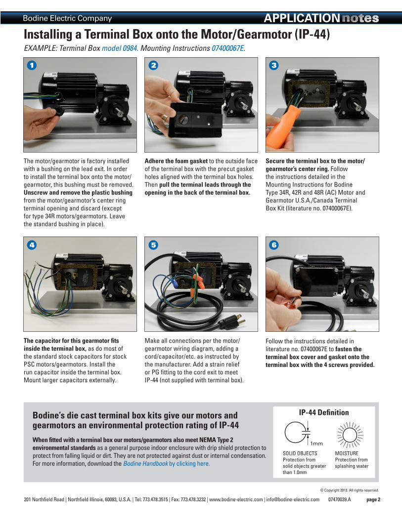
The motor/gearmotor is factory installed with a bushing on the lead exit. In order to install the terminal box onto the motor/gearmotor, this bushing must be removed. Unscrew and remove the plastic bushing from the motor/gearmotor’s center ring terminal opening and discard (except for type 34R motors/gearmotors. Leave the standard bushing in place).
Installing a Terminal Box onto the Motor/Gearmotor (IP-44)EXAMPLE: Terminal Box model 0984. Mounting Instructions 07400067E.
Adhere the foam gasket to the outside face of the terminal box with the precut gasket holes aligned with the terminal box holes. Then pull the terminal leads through the opening in the back of the terminal box.
Secure the terminal box to the motor/gearmotor’s center ring. Follow the instructions detailed in the Mounting Instructions for Bodine Type 34R, 42R and 48R (AC) Motor and Gearmotor U.S.A./Canada Terminal Box Kit (literature no. 07400067E).
The capacitor for this gearmotor fits inside the terminal box, as do most of the standard stock capacitors for stock PSC motors/gearmotors. Install the run capacitor inside the terminal box.Mount larger capacitors externally.
Make all connections per the motor/gearmotor wiring diagram, adding a cord/capacitor/etc. as instructed by the manufacturer. Add a strain relief or PG fitting to the cord exit to meet IP-44 (not supplied with terminal box).
1
4
2
5
3
6
Follow the instructions detailed in literature no. 07400067E to fasten the terminal box cover and gasket onto the terminal box with the 4 screws provided.
1mm1mm
SoLID oBjECTS Protection from solid objects greater than 1.0mm
IP-44 Definition
MoISTURE Protection from splashing water
© Copyright 2013. All rights reserved.