
Bobcat 250 NT - Miller · Bobcat 250 NT Processes Description Non-Critical TIG (GTAW) Welding Stick...
80
Bobcat 250 NT Processes Description Non-Critical TIG (GTAW) Welding Stick (SMAW) Welding MIG (GMAW) Welding Flux Cored (FCAW) Welding Engine Driven Welding Generator OM-4403 200 291L April 2004 Visit our website at www.MillerWelds.com
Transcript of Bobcat 250 NT - Miller · Bobcat 250 NT Processes Description Non-Critical TIG (GTAW) Welding Stick...

Bobcat 250 NT
Processes
Description
Non-Critical TIG (GTAW)Welding
Stick (SMAW) Welding
MIG (GMAW) WeldingFlux Cored (FCAW) Welding
Engine Driven Welding Generator
OM-4403 200 291L
April 2004
Visit our website at
www.MillerWelds.com

Miller Electric manufactures a full lineof welders and welding related equipment.For information on other quality Millerproducts, contact your local Miller distributor to receive the latest fullline catalog or individual catalog sheets. To locate your nearestdistributor or service agency call 1-800-4-A-Miller, or visit us atwww.MillerWelds.com on the web.
Thank you and congratulations on choosing Miller. Now you can getthe job done and get it done right. We know you don’t have time to doit any other way.
That’s why when Niels Miller first started building arc welders in 1929,he made sure his products offered long-lasting value and superiorquality. Like you, his customers couldn’t afford anything less. Millerproducts had to be more than the best they could be. They had to be thebest you could buy.
Today, the people that build and sell Miller products continue thetradition. They’re just as committed to providing equipment and servicethat meets the high standards of quality and value established in 1929.
This Owner’s Manual is designed to help you get the most out of yourMiller products. Please take time to read the Safety precautions. Theywill help you protect yourself against potential hazards on the worksite.
We’ve made installation and operation quickand easy. With Miller you can count on yearsof reliable service with proper maintenance.And if for some reason the unit needs repair,there’s a Troubleshooting section that willhelp you figure out what the problem is. Theparts list will then help you to decide theexact part you may need to fix the problem.Warranty and service information for yourparticular model are also provided.
Miller is the first weldingequipment manufacturer inthe U.S.A. to be registered tothe ISO 9001:2000 QualitySystem Standard.
Working as hard as you do− every power source fromMiller is backed by the mosthassle-free warranty in thebusiness.
From Miller to You
Mil_Thank 7/03

TABLE OF CONTENTS
SECTION 1 − SAFETY PRECAUTIONS − READ BEFORE USING 1 . . . . . . . . . . . . . . . . . . . . . . . . . . . . . . . . . . 1-1. Symbol Usage 1 . . . . . . . . . . . . . . . . . . . . . . . . . . . . . . . . . . . . . . . . . . . . . . . . . . . . . . . . . . . . . . . . . . . . . . . . 1-2. Arc Welding Hazards 1 . . . . . . . . . . . . . . . . . . . . . . . . . . . . . . . . . . . . . . . . . . . . . . . . . . . . . . . . . . . . . . . . . . 1-3. Engine Hazards 2 . . . . . . . . . . . . . . . . . . . . . . . . . . . . . . . . . . . . . . . . . . . . . . . . . . . . . . . . . . . . . . . . . . . . . . 1-4. Compressed Air Hazards 3 . . . . . . . . . . . . . . . . . . . . . . . . . . . . . . . . . . . . . . . . . . . . . . . . . . . . . . . . . . . . . . . 1-5. Additional Symbols For Installation, Operation, And Maintenance 3 . . . . . . . . . . . . . . . . . . . . . . . . . . . . . 1-6. California Proposition 65 Warnings 4 . . . . . . . . . . . . . . . . . . . . . . . . . . . . . . . . . . . . . . . . . . . . . . . . . . . . . . . 1-7. Principal Safety Standards 4 . . . . . . . . . . . . . . . . . . . . . . . . . . . . . . . . . . . . . . . . . . . . . . . . . . . . . . . . . . . . . 1-8. EMF Information 4 . . . . . . . . . . . . . . . . . . . . . . . . . . . . . . . . . . . . . . . . . . . . . . . . . . . . . . . . . . . . . . . . . . . . . .
SECTION 2 − CONSIGNES DE SÉCURITÉ − LIRE AVANT UTILISATION 5 . . . . . . . . . . . . . . . . . . . . . . . . . . . . 2-1. Signification des symboles 5 . . . . . . . . . . . . . . . . . . . . . . . . . . . . . . . . . . . . . . . . . . . . . . . . . . . . . . . . . . . . . 2-2. Dangers relatifs au soudage à l’arc 5 . . . . . . . . . . . . . . . . . . . . . . . . . . . . . . . . . . . . . . . . . . . . . . . . . . . . . . 2-3. Dangers existant en relation avec le moteur 6 . . . . . . . . . . . . . . . . . . . . . . . . . . . . . . . . . . . . . . . . . . . . . . . 2-4. Dangers liés à l’air comprimé 7 . . . . . . . . . . . . . . . . . . . . . . . . . . . . . . . . . . . . . . . . . . . . . . . . . . . . . . . . . . . 2-5. Dangers supplémentaires en relation avec l’installation, le fonctionnement et la maintenance 7 . . . . . . 2-6. Principales normes de sécurité 8 . . . . . . . . . . . . . . . . . . . . . . . . . . . . . . . . . . . . . . . . . . . . . . . . . . . . . . . . . . 2-7. Information sur les champs électromagnétiques 8 . . . . . . . . . . . . . . . . . . . . . . . . . . . . . . . . . . . . . . . . . . . .
SECTION 3 − DEFINITIONS 9 . . . . . . . . . . . . . . . . . . . . . . . . . . . . . . . . . . . . . . . . . . . . . . . . . . . . . . . . . . . . . . . . . . . SECTION 4 − SPECIFICATIONS 9 . . . . . . . . . . . . . . . . . . . . . . . . . . . . . . . . . . . . . . . . . . . . . . . . . . . . . . . . . . . . . . . .
4-1. Weld, Power, and Engine Specifications 9 . . . . . . . . . . . . . . . . . . . . . . . . . . . . . . . . . . . . . . . . . . . . . . . . . . 4-2. Dimensions, Weights, and Operating Angles 10 . . . . . . . . . . . . . . . . . . . . . . . . . . . . . . . . . . . . . . . . . . . . . . . 4-3. Generator Power Curve 10 . . . . . . . . . . . . . . . . . . . . . . . . . . . . . . . . . . . . . . . . . . . . . . . . . . . . . . . . . . . . . . . . 4-4. Fuel Consumption (Onan-Powered Units) 11 . . . . . . . . . . . . . . . . . . . . . . . . . . . . . . . . . . . . . . . . . . . . . . . . . 4-5. Fuel Consumption (Kohler-Powered Units) 11 . . . . . . . . . . . . . . . . . . . . . . . . . . . . . . . . . . . . . . . . . . . . . . . . 4-6. Volt-Ampere Curves 12 . . . . . . . . . . . . . . . . . . . . . . . . . . . . . . . . . . . . . . . . . . . . . . . . . . . . . . . . . . . . . . . . . . . 4-7. Duty Cycle 13 . . . . . . . . . . . . . . . . . . . . . . . . . . . . . . . . . . . . . . . . . . . . . . . . . . . . . . . . . . . . . . . . . . . . . . . . . . .
SECTION 5 − INSTALLATION 14 . . . . . . . . . . . . . . . . . . . . . . . . . . . . . . . . . . . . . . . . . . . . . . . . . . . . . . . . . . . . . . . . . . 5-1. Installing Welding Generator 14 . . . . . . . . . . . . . . . . . . . . . . . . . . . . . . . . . . . . . . . . . . . . . . . . . . . . . . . . . . . . 5-2. Engine Prestart Checks (Onan-Powered Units) 15 . . . . . . . . . . . . . . . . . . . . . . . . . . . . . . . . . . . . . . . . . . . . 5-3. Engine Prestart Checks (Kohler-Powered Units) 16 . . . . . . . . . . . . . . . . . . . . . . . . . . . . . . . . . . . . . . . . . . . 5-4. Activating The Dry Charge Battery (If Applicable) 17 . . . . . . . . . . . . . . . . . . . . . . . . . . . . . . . . . . . . . . . . . . . 5-5. Connecting the Battery 18 . . . . . . . . . . . . . . . . . . . . . . . . . . . . . . . . . . . . . . . . . . . . . . . . . . . . . . . . . . . . . . . . . 5-6. Installing Exhaust Pipe 18 . . . . . . . . . . . . . . . . . . . . . . . . . . . . . . . . . . . . . . . . . . . . . . . . . . . . . . . . . . . . . . . . . 5-7. Connecting to Weld Output Terminals 19 . . . . . . . . . . . . . . . . . . . . . . . . . . . . . . . . . . . . . . . . . . . . . . . . . . . . 5-8. Selecting Weld Cable Sizes* 19 . . . . . . . . . . . . . . . . . . . . . . . . . . . . . . . . . . . . . . . . . . . . . . . . . . . . . . . . . . . .
SECTION 6 − OPERATING THE WELDING GENERATOR 20 . . . . . . . . . . . . . . . . . . . . . . . . . . . . . . . . . . . . . . . . . 6-1. Front Panel Controls 20 . . . . . . . . . . . . . . . . . . . . . . . . . . . . . . . . . . . . . . . . . . . . . . . . . . . . . . . . . . . . . . . . . . . 6-2. Typical Stick Welding Connections And Control Settings 21 . . . . . . . . . . . . . . . . . . . . . . . . . . . . . . . . . . . . . 6-3. Typical MIG Welding Connections And Settings 22 . . . . . . . . . . . . . . . . . . . . . . . . . . . . . . . . . . . . . . . . . . . . 6-4. Typical MIG Connections And Settings Using Weld Control And Spoolgun 24 . . . . . . . . . . . . . . . . . . . . . .
SECTION 7 − OPERATING AUXILIARY EQUIPMENT 25 . . . . . . . . . . . . . . . . . . . . . . . . . . . . . . . . . . . . . . . . . . . . . 7-1. Standard Receptacles 25 . . . . . . . . . . . . . . . . . . . . . . . . . . . . . . . . . . . . . . . . . . . . . . . . . . . . . . . . . . . . . . . . . 7-2. Optional Generator Power Receptacles 26 . . . . . . . . . . . . . . . . . . . . . . . . . . . . . . . . . . . . . . . . . . . . . . . . . . . 7-3. Wiring Optional 240 Volt Plug 27 . . . . . . . . . . . . . . . . . . . . . . . . . . . . . . . . . . . . . . . . . . . . . . . . . . . . . . . . . . .
SECTION 8 − MAINTENANCE (ONAN-POWERED UNITS) 28 . . . . . . . . . . . . . . . . . . . . . . . . . . . . . . . . . . . . . . . . . 8-1. Routine Maintenance (Onan-Powered Units) 28 . . . . . . . . . . . . . . . . . . . . . . . . . . . . . . . . . . . . . . . . . . . . . . 8-2. Maintenance Label (Onan-Powered Units) 29 . . . . . . . . . . . . . . . . . . . . . . . . . . . . . . . . . . . . . . . . . . . . . . . . 8-3. Servicing Air Cleaner (Onan-Powered Units) 30 . . . . . . . . . . . . . . . . . . . . . . . . . . . . . . . . . . . . . . . . . . . . . . 8-4. Overload Protection (Onan-Powered Units) 30 . . . . . . . . . . . . . . . . . . . . . . . . . . . . . . . . . . . . . . . . . . . . . . . 8-5. Changing Engine Oil, Oil Filter, and Fuel Filter (Onan-Powered Units) 31 . . . . . . . . . . . . . . . . . . . . . . . . . . 8-6. Adjusting Engine Speed (Onan-Powered Units) 32 . . . . . . . . . . . . . . . . . . . . . . . . . . . . . . . . . . . . . . . . . . . . 8-7. Servicing Optional Spark Arrestor (Onan-Powered Units) 33 . . . . . . . . . . . . . . . . . . . . . . . . . . . . . . . . . . . .

TABLE OF CONTENTS
SECTION 9 − MAINTENANCE − (KOHLER-POWERED UNITS) 33 . . . . . . . . . . . . . . . . . . . . . . . . . . . . . . . . . . . . . 9-1. Maintenance Label (Kohler-Powered Units) 33 . . . . . . . . . . . . . . . . . . . . . . . . . . . . . . . . . . . . . . . . . . . . . . . 9-2. Routine Maintenance (Kohler-Powered Units) 34 . . . . . . . . . . . . . . . . . . . . . . . . . . . . . . . . . . . . . . . . . . . . . . 9-3. Servicing Air Cleaner (Kohler-Powered Units) 35 . . . . . . . . . . . . . . . . . . . . . . . . . . . . . . . . . . . . . . . . . . . . . . 9-4. Changing Engine Oil, Oil Filter, and Fuel Filter (Kohler-Powered Units) 36 . . . . . . . . . . . . . . . . . . . . . . . . .
9-5. Adjusting Engine Speed (Kohler-Powered Units) 37 . . . . . . . . . . . . . . . . . . . . . . . . . . . . . . . . . . . . . . . . . . . 9-6. Overload Protection (Kohler-Powered Units) 38 . . . . . . . . . . . . . . . . . . . . . . . . . . . . . . . . . . . . . . . . . . . . . . . 9-7. Servicing Optional Spark Arrestor (Kohler-Powered Units) 38 . . . . . . . . . . . . . . . . . . . . . . . . . . . . . . . . . . .
SECTION 10 − TROUBLESHOOTING 39 . . . . . . . . . . . . . . . . . . . . . . . . . . . . . . . . . . . . . . . . . . . . . . . . . . . . . . . . . . . SECTION 11 − ELECTRICAL DIAGRAMS 42 . . . . . . . . . . . . . . . . . . . . . . . . . . . . . . . . . . . . . . . . . . . . . . . . . . . . . . . SECTION 12 − GENERATOR POWER GUIDELINES 44 . . . . . . . . . . . . . . . . . . . . . . . . . . . . . . . . . . . . . . . . . . . . . . SECTION 13 − STICK WELDING (SMAW) GUIDELINES 51 . . . . . . . . . . . . . . . . . . . . . . . . . . . . . . . . . . . . . . . . . . . SECTION 14 − MIG WELDING (GMAW) GUIDELINES 59 . . . . . . . . . . . . . . . . . . . . . . . . . . . . . . . . . . . . . . . . . . . . .
14-1. Typical MIG Process Connections Using A Voltage-Sensing Wire Feeder 59 . . . . . . . . . . . . . . . . . . . . . .
14-2. Typical MIG Process Connections Using A Constant Speed Wire Feeder 59 . . . . . . . . . . . . . . . . . . . . . . 14-3. Typical MIG Process Control Settings 60 . . . . . . . . . . . . . . . . . . . . . . . . . . . . . . . . . . . . . . . . . . . . . . . . . . . . 14-4. Holding And Positioning Welding Gun 61 . . . . . . . . . . . . . . . . . . . . . . . . . . . . . . . . . . . . . . . . . . . . . . . . . . . . 14-5. Conditions That Affect Weld Bead Shape 62 . . . . . . . . . . . . . . . . . . . . . . . . . . . . . . . . . . . . . . . . . . . . . . . . . 14-6. Gun Movement During Welding 63 . . . . . . . . . . . . . . . . . . . . . . . . . . . . . . . . . . . . . . . . . . . . . . . . . . . . . . . . .
14-7. Poor Weld Bead Characteristics 63 . . . . . . . . . . . . . . . . . . . . . . . . . . . . . . . . . . . . . . . . . . . . . . . . . . . . . . . . . 14-8. Good Weld Bead Characteristics 63 . . . . . . . . . . . . . . . . . . . . . . . . . . . . . . . . . . . . . . . . . . . . . . . . . . . . . . . . 14-9. Troubleshooting − Excessive Spatter 64 . . . . . . . . . . . . . . . . . . . . . . . . . . . . . . . . . . . . . . . . . . . . . . . . . . . . . 14-10. Troubleshooting − Porosity 64 . . . . . . . . . . . . . . . . . . . . . . . . . . . . . . . . . . . . . . . . . . . . . . . . . . . . . . . . . . . 14-11. Troubleshooting − Excessive Penetration 64 . . . . . . . . . . . . . . . . . . . . . . . . . . . . . . . . . . . . . . . . . . . . . . .
14-12. Troubleshooting − Lack Of Penetration 65 . . . . . . . . . . . . . . . . . . . . . . . . . . . . . . . . . . . . . . . . . . . . . . . . . 14-13. Troubleshooting − Incomplete Fusion 65 . . . . . . . . . . . . . . . . . . . . . . . . . . . . . . . . . . . . . . . . . . . . . . . . . . 14-14. Troubleshooting − Burn-Through 65 . . . . . . . . . . . . . . . . . . . . . . . . . . . . . . . . . . . . . . . . . . . . . . . . . . . . . . 14-15. Troubleshooting − Waviness Of Bead 66 . . . . . . . . . . . . . . . . . . . . . . . . . . . . . . . . . . . . . . . . . . . . . . . . . . 14-16. Troubleshooting − Distortion 66 . . . . . . . . . . . . . . . . . . . . . . . . . . . . . . . . . . . . . . . . . . . . . . . . . . . . . . . . . .
14-17. Common MIG Shielding Gases 67 . . . . . . . . . . . . . . . . . . . . . . . . . . . . . . . . . . . . . . . . . . . . . . . . . . . . . . . SECTION 15 − PARTS LIST 68 . . . . . . . . . . . . . . . . . . . . . . . . . . . . . . . . . . . . . . . . . . . . . . . . . . . . . . . . . . . . . . . . . . . OPTIONS AND ACCESSORIESWARRANTY

OM-4403 Page 1
SECTION 1 − SAFETY PRECAUTIONS − READ BEFORE USINGrom _nd_8/03
� Warning: Protect yourself and others from injury — read and follow these precautions.
1-1. Symbol Usage
Means Warning! Watch Out! There are possible hazardswith this procedure! The possible hazards are shown inthe adjoining symbols.
� Marks a special safety message.
� Means “Note”; not safety related.
This group of symbols means Warning! Watch Out! possibleELECTRIC SHOCK, MOVING PARTS, and HOT PARTS hazards.Consult symbols and related instructions below for necessary actionsto avoid the hazards.
1-2. Arc Welding Hazards
� The symbols shown below are used throughout this manual tocall attention to and identify possible hazards. When you see thesymbol, watch out, and follow the related instructions to avoid thehazard. The safety information given below is only a summary ofthe more complete safety information found in the Safety Stan-dards listed in Section 1-7. Read and follow all Safety Standards.
� Only qualified persons should install, operate, maintain, and re-pair this unit.
� During operation, keep everybody, especially children, away.
Touching live electrical parts can cause fatal shocks orsevere burns. The electrode and work circuit is electricallylive whenever the output is on. The input power circuit and
machine internal circuits are also live when power is on. In semiautomatic orautomatic wire welding, the wire, wire reel, drive roll housing, and all metalparts touching the welding wire are electrically live. Incorrectly installed orimproperly grounded equipment is a hazard.
ELECTRIC SHOCK can kill.
� Do not touch live electrical parts.
� Wear dry, hole-free insulating gloves and body protection.
� Insulate yourself from work and ground using dry insulating mats or coversbig enough to prevent any physical contact with the work or ground.
� Do not use AC output in damp areas, if movement is confined, or if there is adanger of falling.
� Use AC output ONLY if required for the welding process.
� If AC output is required, use remote output control if present on unit.
� Additional safety precautions are required when any of the following electri-cally hazardous conditions are present: in damp locations or while wearingwet clothing; on metal structures such as floors, gratings, or scaffolds;when in cramped positions such as sitting, kneeling, or lying; or when thereis a high risk of unavoidable or accidental contact with the workpiece orground. For these conditions, use the following equipment in order present-ed: 1) a semiautomatic DC constant voltage (wire) welder, 2) a DC manual(stick) welder, or 3) an AC welder with reduced open-circuit voltage. In mostsituations, use of a DC, constant voltage wire welder is recommended.And, do not work alone!
� Disconnect input power or stop engine before installing or servicing thisequipment. Lockout/tagout input power according to OSHA 29 CFR1910.147 (see Safety Standards).
� Properly install and ground this equipment according to its Owner’s Manualand national, state, and local codes.
� Always verify the supply ground — check and be sure that input power cordground wire is properly connected to ground terminal in disconnect box orthat cord plug is connected to a properly grounded receptacle outlet.
� When making input connections, attach proper grounding conductor first −double-check connections.
� Frequently inspect input power cord for damage or bare wiring — replacecord immediately if damaged — bare wiring can kill.
� Turn off all equipment when not in use.
� Do not use worn, damaged, undersized, or poorly spliced cables.
� Do not drape cables over your body.
� If earth grounding of the workpiece is required, ground it directly with a sep-arate cable.
� Do not touch electrode if you are in contact with the work, ground, or anoth-er electrode from a different machine.
� Use only well-maintained equipment. Repair or replace damaged parts atonce. Maintain unit according to manual.
� Wear a safety harness if working above floor level.
� Keep all panels and covers securely in place.
� Clamp work cable with good metal-to-metal contact to workpiece or work-table as near the weld as practical.
� Insulate work clamp when not connected to workpiece to prevent contactwith any metal object.
� Do not connect more than one electrode or work cable to any single weldoutput terminal.
SIGNIFICANT DC VOLTAGE exists in inverters after stop-ping engine.� Stop engine on inverter and discharge input capacitors according to
instructions in Maintenance Section before touching any parts.
Welding produces fumes and gases. Breathing these fumesand gases can be hazardous to your health.
FUMES AND GASES can be hazardous.
� Keep your head out of the fumes. Do not breathe the fumes.
� If inside, ventilate the area and/or use exhaust at the arc to remove weldingfumes and gases.
� If ventilation is poor, use an approved air-supplied respirator.� Read the Material Safety Data Sheets (MSDSs) and the manufacturer’s
instructions for metals, consumables, coatings, cleaners, and degreasers.� Work in a confined space only if it is well ventilated, or while wearing an air-
supplied respirator. Always have a trained watchperson nearby. Weldingfumes and gases can displace air and lower the oxygen level causing injuryor death. Be sure the breathing air is safe.
� Do not weld in locations near degreasing, cleaning, or spraying operations.The heat and rays of the arc can react with vapors to form highly toxic andirritating gases.
� Do not weld on coated metals, such as galvanized, lead, or cadmium platedsteel, unless the coating is removed from the weld area, the area is wellventilated, and if necessary, while wearing an air-supplied respirator. Thecoatings and any metals containing these elements can give off toxic fumesif welded.
BUILDUP OF GAS can injure or kill.
� Shut off shielding gas supply when not in use.� Always ventilate confined spaces or use approved
air-supplied respirator.
Arc rays from the welding process produce intense visibleand invisible (ultraviolet and infrared) rays that can burn eyesand skin. Sparks fly off from the weld.
ARC RAYS can burn eyes and skin.
� Wear a welding helmet fitted with a proper shade of filter to protect your faceand eyes from arc rays and sparks when welding or watching (see ANSIZ49.1 and Z87.1 listed in Safety Standards).
� Wear approved safety glasses with side shields under your helmet.
� Use protective screens or barriers to protect others from flash and glare;warn others not to watch the arc.
� Wear protective clothing made from durable, flame-resistant material (wooland leather) and foot protection.

OM-4403 Page 2
Welding on closed containers, such as tanks, drums, orpipes, can cause them to blow up. Sparks can fly off from thewelding arc. The flying sparks, hot workpiece, and hot
equipment can cause fires and burns. Accidental contact of electrode to metalobjects can cause sparks, explosion, overheating, or fire. Check and be surethe area is safe before doing any welding.
WELDING can cause fire or explosion.
� Protect yourself and others from flying sparks and hot metal.
� Do not weld where flying sparks can strike flammable material.
� Remove all flammables within 35 ft (10.7 m) of the welding arc. If this is notpossible, tightly cover them with approved covers.
� Be alert that welding sparks and hot materials from welding can easily gothrough small cracks and openings to adjacent areas.
� Watch for fire, and keep a fire extinguisher nearby.
� Be aware that welding on a ceiling, floor, bulkhead, or partition can causefire on the hidden side.
� Do not weld on closed containers such as tanks, drums, or pipes, unlessthey are properly prepared according to AWS F4.1 (see Safety Standards).
� Connect work cable to the work as close to the welding area as practical toprevent welding current from traveling long, possibly unknown paths andcausing electric shock and fire hazards.
� Do not use welder to thaw frozen pipes.
� Remove stick electrode from holder or cut off welding wire at contact tipwhen not in use.
� Wear oil-free protective garments such as leather gloves, heavy shirt, cuf-fless trousers, high shoes, and a cap.
� Remove any combustibles, such as a butane lighter or matches, from yourperson before doing any welding.
� Follow requirements in OSHA 1910.252 (a) (2) (iv) and NFPA 51B for hotwork and have a fire watcher and extinguisher nearby.
FLYING METAL can injure eyes.
� Welding, chipping, wire brushing, and grinding causesparks and flying metal. As welds cool, they canthrow off slag.
� Wear approved safety glasses with side shields evenunder your welding helmet.
HOT PARTS can cause severe burns.
� Allow cooling period before maintaining.� Wear protective gloves and clothing when working on
a hot engine.� Do not touch hot engine parts or just-welded parts
bare-handed.
NOISE can damage hearing.
Noise from some processes or equipment can damagehearing.
� Wear approved ear protection if noise level is high.
MAGNETIC FIELDS can affect pacemakers.
� Pacemaker wearers keep away.� Wearers should consult their doctor before going
near arc welding, gouging, or spot welding opera-tions.
Shielding gas cylinders contain gas under high pressure. Ifdamaged, a cylinder can explode. Since gas cylinders arenormally part of the welding process, be sure to treat themcarefully.
CYLINDERS can explode if damaged.
� Protect compressed gas cylinders from excessive heat, mechanicalshocks, slag, open flames, sparks, and arcs.
� Install cylinders in an upright position by securing to a stationary support orcylinder rack to prevent falling or tipping.
� Keep cylinders away from any welding or other electrical circuits.
� Never drape a welding torch over a gas cylinder.
� Never allow a welding electrode to touch any cylinder.
� Never weld on a pressurized cylinder — explosion will result.
� Use only correct shielding gas cylinders, regulators, hoses, and fittings de-signed for the specific application; maintain them and associated parts ingood condition.
� Turn face away from valve outlet when opening cylinder valve.
� Keep protective cap in place over valve except when cylinder is in use orconnected for use.
� Read and follow instructions on compressed gas cylinders, associatedequipment, and CGA publication P-1 listed in Safety Standards.
1-3. Engine Hazards
BATTERY EXPLOSION can BLIND.
� Always wear a face shield, rubber gloves, and protec-tive clothing when working on a battery.
� Stop engine before disconnecting or connecting bat-tery cables or servicing battery.
� Do not allow tools to cause sparks when working on a battery.
� Do not use welder to charge batteries or jump start vehicles.
� Observe correct polarity (+ and −) on batteries.
� Disconnect negative (−) cable first and connect it last.
FUEL can cause fire or explosion.
� Stop engine and let it cool off before checking or add-ing fuel.
� Do not add fuel while smoking or if unit is near anysparks or open flames.
� Do not overfill tank — allow room for fuel to expand.
� Do not spill fuel. If fuel is spilled, clean up before starting engine.
� Dispose of rags in a fireproof container.
� Always keep nozzle in contact with tank when fueling.
MOVING PARTS can cause injury.
� Keep away from fans, belts, and rotors.� Keep all doors, panels, covers, and guards closed
and securely in place.
� Stop engine before installing or connecting unit.
� Have only qualified people remove guards or covers for maintenanceand troubleshooting as necessary.
� To prevent accidental starting during servicing, disconnect negative (−)battery cable from battery.
� Keep hands, hair, loose clothing, and tools away from moving parts.
� Reinstall panels or guards and close doors when servicing is finishedand before starting engine.
� Before working on generator, remove spark plugs or injectors to keepengine from kicking back or starting.
� Block flywheel so that it will not turn while working on generator compo-nents.

OM-4403 Page 3
STEAM AND HOT COOLANT can burn.
� If possible, check coolant level when engine is cold toavoid scalding.
� Always check coolant level at overflow tank, if pres-ent on unit, instead of radiator (unless told otherwisein maintenance section or engine manual).
� If the engine is warm, checking is needed, and there is no overflow tank,follow the next two statements.
� Wear safety glasses and gloves and put a rag over radiator cap.
� Turn cap slightly and let pressure escape slowly before completely re-moving cap.
ENGINE EXHAUST GASES can kill.
� Use equipment outside in open, well-ventilated ar-eas.
� If used in a closed area, vent engine exhaust outsideand away from any building air intakes.
BATTERY ACID can BURN SKIN and EYES.
� Do not tip battery.� Replace damaged battery.
� Flush eyes and skin immediately with water.
ENGINE HEAT can cause fire.
� Do not locate unit on, over, or near combustiblesurfaces or flammables.
� Keep exhaust and exhaust pipes way from flam-mables.
EXHAUST SPARKS can cause fire.
� Do not let engine exhaust sparks cause fire.
� Use approved engine exhaust spark arrestor in re-quired areas — see applicable codes.
1-4. Compressed Air Hazards
BREATHING COMPRESSED AIR cancause serious injury or death.
� Do not use compressed air for breathing.� Use only for cutting, gouging, and tools.
COMPRESSED AIR can cause injury.
� Wear approved safety goggles.� Do not direct air stream toward self or others.
TRAPPED AIR PRESSURE AND WHIPPINGHOSES can cause injury.
� Release air pressure from tools and system beforeservicing, adding or changing attachments, or open-ing compressor oil drain or oil fill cap.
HOT METAL from air arc cutting andgouging can cause fire or explosion.
� Do not cut or gouge near flammables.� Watch for fire; keep extinguisher nearby.
HOT PARTS can cause burns and injury.
� Do not touch hot compressor or air system parts.� Let system cool down before touching or servicing.
READ INSTRUCTIONS.
� Read Owner’s Manual before using or servicing unit.� Stop engine and release air pressure before
servicing.
1-5. Additional Symbols For Installation, Operation, And Maintenance
FALLING UNIT can cause injury.
� Use lifting eye to lift unit only, NOT running gear, gascylinders, trailer, or any other accessories.
� Use equipment of adequate capacity to lift andsupport unit.
� If using lift forks to move unit, be sure forks are longenough to extend beyond opposite side of unit.
OVERHEATING can damage motors.
� Turn off or unplug equipment before starting or stop-ping engine.
� Do not let low voltage and frequency caused by lowengine speed damage electric motors.
� Do not connect 50 or 60 Hertz motors to the 100 Hertz receptacle whereapplicable.
FLYING SPARKS can cause injury.
� Wear a face shield to protect eyes and face.� Shape tungsten electrode only on grinder with proper
guards in a safe location wearing proper face, hand,and body protection.
� Sparks can cause fires — keep flammables away.
OVERUSE can cause OVERHEATING.
� Allow cooling period; follow rated duty cycle.� Reduce current or reduce duty cycle before starting
to weld again.� Do not block or filter airflow to unit.
STATIC (ESD) can damage PC boards.
� Put on grounded wrist strap BEFORE handlingboards or parts.
� Use proper static-proof bags and boxes to store,move, or ship PC boards.
TILTING OF TRAILER can cause injury.
� Use tongue jack or blocks to support weight.� Properly install welding generator onto trailer accord-
ing to instructions supplied with trailer.

OM-4403 Page 4
READ INSTRUCTIONS.
� Use only genuine MILLER/Hobart replacementparts.
� Perform engine and air compressor (if applicable)maintenance and service according to this manualand the engine/air compressor (if applicable) manu-als.
H.F. RADIATION can cause interference.
� High-frequency (H.F.) can interfere with radio naviga-tion, safety services, computers, and communica-tions equipment.
� Have only qualified persons familiar with electronicequipment perform this installation.
� The user is responsible for having a qualified electricianpromptly correct any interference problem resulting from the installation.
� If notified by the FCC about interference, stop using the equipment atonce.
� Have the installation regularly checked and maintained.
� Keep high-frequency source doors and panels tightly shut, keep sparkgaps at correct setting, and use grounding and shielding to minimize thepossibility of interference.
ARC WELDING can cause interference.
� Electromagnetic energy can interfere with sensitiveelectronic equipment such as microprocessors,computers, and computer-driven equipment such asrobots.
� Be sure all equipment in the welding area is electro-magnetically compatible.
� To reduce possible interference, keep weld cables as short as possible,close together, and down low, such as on the floor.
� Locate welding operation 100 meters from any sensitive electronicequipment.
� Be sure this welding machine is installed and grounded according to thismanual.
� If interference still occurs, the user must take extra measures such asmoving the welding machine, using shielded cables, using line filters, orshielding the work area.
1-6. California Proposition 65 Warnings
� Welding or cutting equipment produces fumes or gases whichcontain chemicals known to the State of California to causebirth defects and, in some cases, cancer. (California Health &Safety Code Section 25249.5 et seq.)
� Battery posts, terminals and related accessories contain leadand lead compounds, chemicals known to the State ofCalifornia to cause cancer and birth defects or otherreproductive harm. Wash hands after handling.
For Gasoline Engines:� Engine exhaust contains chemicals known to the State of
California to cause cancer, birth defects, or other reproductiveharm.
For Diesel Engines:� Diesel engine exhaust and some of its constituents are known
to the State of California to cause cancer, birth defects, andother reproductive harm.
1-7. Principal Safety Standards
Safety in Welding, Cutting, and Allied Processes, ANSI Standard Z49.1,from American Welding Society, 550 N.W. LeJeune Rd, Miami FL 33126(phone: 305-443-9353, website: www.aws.org).Recommended Safe Practices for the Preparation for Welding and Cut-ting of Containers and Piping, American Welding Society StandardAWS F4.1, from American Welding Society, 550 N.W. LeJeune Rd, Mi-ami, FL 33126 (phone: 305-443-9353, website: www.aws.org).National Electrical Code, NFPA Standard 70, from National Fire Protec-tion Association, P.O. Box 9101, 1 Battery March Park, Quincy, MA02269-9101 (phone: 617-770-3000, website: www.nfpa.org and www.sparky.org).Safe Handling of Compressed Gases in Cylinders, CGA Pamphlet P-1,from Compressed Gas Association, 1735 Jefferson Davis Highway,Suite 1004, Arlington, VA 22202-4102 (phone: 703-412-0900, website:www.cganet.com).Code for Safety in Welding and Cutting, CSA Standard W117.2, fromCanadian Standards Association, Standards Sales, 178 Rexdale Bou-
levard, Rexdale, Ontario, Canada M9W 1R3 (phone: 800-463-6727 orin Toronto 416-747-4044, website: www.csa-international.org).
Practice For Occupational And Educational Eye And Face Protection,ANSI Standard Z87.1, from American National Standards Institute, 11West 42nd Street, New York, NY 10036–8002 (phone: 212-642-4900,website: www.ansi.org).
Standard for Fire Prevention During Welding, Cutting, and Other HotWork, NFPA Standard 51B, from National Fire Protection Association,P.O. Box 9101, 1 Battery March Park, Quincy, MA 02269-9101 (phone:617-770-3000, website: www.nfpa.org and www. sparky.org).
OSHA, Occupational Safety and Health Standards for General Indus-try, Title 29, Code of Federal Regulations (CFR), Part 1910, Subpart Q,and Part 1926, Subpart J, from U.S. Government Printing Office, Super-intendent of Documents, P.O. Box 371954, Pittsburgh, PA 15250 (thereare 10 Regional Offices—phone for Region 5, Chicago, is312-353-2220, website: www.osha.gov).
1-8. EMF InformationConsiderations About Welding And The Effects Of Low FrequencyElectric And Magnetic Fields
Welding current, as it flows through welding cables, will cause electro-magnetic fields. There has been and still is some concern about suchfields. However, after examining more than 500 studies spanning 17years of research, a special blue ribbon committee of the NationalResearch Council concluded that: “The body of evidence, in thecommittee’s judgment, has not demonstrated that exposure to power-frequency electric and magnetic fields is a human-health hazard.”However, studies are still going forth and evidence continues to beexamined. Until the final conclusions of the research are reached, youmay wish to minimize your exposure to electromagnetic fields whenwelding or cutting.
To reduce magnetic fields in the workplace, use the followingprocedures:1. Keep cables close together by twisting or taping them.2. Arrange cables to one side and away from the operator.3. Do not coil or drape cables around your body.4. Keep welding power source and cables as far away from
operator as practical.5. Connect work clamp to workpiece as close to the weld as
possible.
About Pacemakers:Pacemaker wearers consult your doctor first. If cleared by your doctor,then following the above procedures is recommended.

OM-4403 Page 5
SECTION 2 − CONSIGNES DE SÉCURITÉ − LIRE AVANTUTILISATION
rom_fre 8/03
� Avertissement: Protégez vous et les autres des blessures − lisez et suivez ces précautions.
2-1. Signification des symboles
Signifie Mise en garde ! Soyez vigilant ! Cette procédureprésente des risques de danger ! Ceux-ci sont identifiés pardes symboles adjacents aux directives.
� Identifie un message de sécurité particulier.
� Signifie NOTA ; n’est pas relatif à la sécurité.
Ce groupe de symboles si-gnifie Mise en garde !Soyez vigilant ! Il y a desrisques de danger reliés
aux CHOCS ÉLECTRIQUES, aux PIÈCES EN MOUVEMENT et auxPIÈCES CHAUDES. Reportez-vous aux symboles et aux directives ci-des-sous afin de connaître les mesures à prendre pour éviter tout danger.
2-2. Dangers relatifs au soudage à l’arc
� Les symboles présentés ci-après sont utilisés tout au long duprésent manuel pour attirer votre attention et identifier les ris-ques de danger. Lorsque vous voyez un symbole, soyezvigilant et suivez les directives mentionnées afin d’éviter toutdanger. Les consignes de sécurité présentées ci-après ne fontque résumer l’information contenue dans les normes de sécu-rité énumérées à la section 2-6 . Veuillez lire et respecter toutesces normes de sécurité.
� L’installation, l’utilisation, l’entretien et les réparations nedoivent être confiés qu’à des personnes qualifiées.
� Au cours de l’utilisation, tenir toute personne à l’écart et plusparticulièrement les enfants.
UN CHOC ÉLECTRIQUE peut tuer.
Un simple contact avec des pièces électriques peutprovoquer une électrocution ou des blessures graves.L’électrode et le circuit de soudage sont sous tension dèsque l’appareil est sur ON. Le circuit d’entrée et les circuitsinternes de l’appareil sont également sous tension à ce
moment-là. En soudage semi-automatique ou automatique, le fil, le dévidoir, lelogement des galets d’entraînement et les pièces métalliques en contact avecle fil de soudage sont sous tension. Des matériels mal installés ou mal mis à laterre présentent un danger.
� Ne jamais toucher les pièces électriques sous tension.
� Porter des gants et des vêtements de protection secs ne comportant pasde trous.
� S’isoler de la pièce et de la terre au moyen de tapis ou d’autres moyens iso-lants suffisamment grands pour empêcher le contact physique éventuelavec la pièce ou la terre.
� Ne pas se servir de source électrique àcourant électrique dans les zoneshumides, dans les endroits confinés ou là où on risque de tomber.
� Se servir d’une source électrique àcourant électrique UNIQUEMENT si leprocédé de soudage le demande.
� Si l’utilisation d’une source électrique àcourant électrique s’avère néces-saire, se servir de la fonction de télécommande si l’appareil en est équipé.
� Des précautions de sécurité supplémentaires sont requises dans des envi-ronnements à risque comme: les endroits humides ou lorsque l’on portedes vêtements mouillés; sur des structures métalliques au sol, grillages etéchafaudages; dans des positions assises, à genoux et allongées; ouquand il y a un risque important de contact accidentel avec la pièce ou lesol. Dans ces cas utiliser les appareils suivants dans l’ordre de préférence:1) un poste à souder DC semi−automatique de type CV (MIG/MAG), 2) unposte à souder manuel (électrode enrobée) DC, 3) un poste à souder ma-nuel AC avec tension à vide réduite. Dans la plupart des cas, un postecourant continu de type CV est recommandé. Et, ne pas travailler seul!
� Couper l’alimentation ou arrêter le moteur avant de procéder à l’installation,à la réparation ou à l’entretien de l’appareil. Déverrouiller l’alimentationselon la norme OSHA 29 CFR 1910.147 (voir normes de sécurité).
� Installer et mettre à la terre correctement cet appareil conformément à sonmanuel d’utilisation et aux codes nationaux, provinciaux et municipaux.
� Toujours vérifier la terre du cordon d’alimentation − Vérifier et s’assurer quele fil de terre du cordon d’alimentation est bien raccordé à la borne de terredu sectionneur ou que la fiche du cordon est raccordée à une prisecorrectement mise à la terre.
� En effectuant les raccordements d’entrée fixer d’abord le conducteur demise à la terre approprié et contre-vérifier les connexions.
� Vérifier fréquemment le cordon d’alimentation pour voir s’il n’est pas en-dommagé ou dénudé − remplacer le cordon immédiatement s’il estendommagé − un câble dénudé peut provoquer une électrocution.
� Mettre l’appareil hors tension quand on ne l’utilise pas.
� Ne pas utiliser des câbles usés, endommagés, de grosseur insuffisante oumal épissés.
� Ne pas enrouler les câbles autour du corps.
� Si la pièce soudée doit être mise à la terre, le faire directement avec uncâble distinct − ne pas utiliser le connecteur de pièce ou le câble de retour.
� Ne pas toucher l’électrode quand on est en contact avec la pièce, la terre ouune électrode provenant d’une autre machine.
� N’utiliser qu’un matériel en bon état. Réparer ou remplacer sur-le-champles pièces endommagées. Entretenir l’appareil conformément à cemanuel.
� Porter un harnais de sécurité quand on travaille en hauteur.
� Maintenir solidement en place tous les panneaux et capots.
� Fixer le câble de retour de façon à obtenir un bon contact métal-métal avecla pièce à souder ou la table de travail, le plus près possible de la soudure.
� Isoler la pince de masse quand pas mis à la pièce pour éviter le contactavec tout objet métallique.
Une tension DC importante subsiste à l’intérieurdes onduleurs après avoir coupé l’alimentation.� Couper l’alimentation du poste et décharger les condensateurs d’entrée
comme indiqué dans la Section Maintenance avant de toucher des compo-sants.
LES FUMÉES ET LES GAZ peuventêtre dangereux.
Le soudage génère des fumées et des gaz. Leur inhalationpeut être dangereux pour votre santé.
� Eloigner votre tête des fumées. Ne pas respirer les fumées.
� À l’interieur, ventiler la zone et/ou utiliser un échappement au niveau del’arc pour l’évacuation des fumées et des gaz de soudage.
� Si la ventilation est insuffisante, utiliser un respirateur à alimentation d’airhomologué.
� Lire les spécifications de sécurité des matériaux (MSDSs) et les instruc-tions du fabricant concernant les métaux, les consommables, lesrevêtements, les nettoyants et les dégraisseurs.
� Travailler dans un espace fermé seulement s’il est bien ventilé ou en por-tant un respirateur à alimentation d’air. Demander toujours à un surveillantdûment formé de se tenir à proximité. Des fumées et des gaz de soudagepeuvent déplacer l’air et abaisser le niveau d’oxygène provoquant desblessures ou des accidents mortels. S’assurer que l’air de respiration neprésente aucun danger.
� Ne pas souder dans des endroits situés à proximité d’opérations de dé-graissage, de nettoyage ou de pulvérisation. La chaleur et les rayons del’arc peuvent réagir en présence de vapeurs et former des gaz hautementtoxiques et irritants.
� Ne pas souder des métaux munis d’un revêtement, tels que l’acier galvani-sé, plaqué en plomb ou au cadmium à moins que le revêtement n’ait étéenlevé dans la zone de soudure, que l’endroit soit bien ventilé, et si néces-saire, en portant un respirateur à alimentation d’air. Les revêtements ettous les métaux renfermant ces éléments peuvent dégager des fuméestoxiques en cas de soudage.

OM-4403 Page 6
LES ACCUMULATIONS DE GAZ ris-quent de provoquer des blessures oumême la mort.
� Fermer l’alimentation du gaz protecteur en cas denon utilisation.
� Veiller toujours à bien aérer les espaces confinés ou se servir d’un respi-rateur d’adduction d’air homologué.
Le rayonnement de l’arc du procédé de soudage génèredes rayons visibles et invisibles intenses (ultraviolets et
infrarouges) susceptibles de provoquer des brûlures dans les yeux et sur lapeau. Des étincelles sont projetées pendant le soudage.
LES RAYONS DE L’ARC peuvent pro-voquer des brûlures dans les yeux etsur la peau.
� Porter un casque de soudage muni d’un écran de filtre approprié pour pro-téger votre visage et vos yeux pendant le soudage ou pour regarder (voirANSI Z49.1 et Z87.1 énuméré dans les normes de sécurité).
� Porter des protections approuvés pour les oreilles si le niveau sondre esttrop élevé.
� Utiliser des écrans ou des barrières pour protéger des tiers de l’éclair et del’éblouissement; demander aux autres personnes de ne pas regarder l’arc.
� Porter des vêtements de protection constitué dans une matière durable, ré-sistant au feu (laine ou cuir) et une protection des pieds.
Le soudage effectué sur des conteneurs fermés tels quedes réservoirs, tambours ou des conduites peut provoquerleur éclatement. Des étincelles peuvent être projetées de
l’arc de soudure. La projection d’étincelles, des pièces chaudes et deséquipements chauds peut provoquer des incendies et des brûlures. Le contactaccidentel de l’électrode avec des objets métalliques peut provoquer desétincelles, une explosion, un surchauffement ou un incendie. Avant decommencer le soudage, vérifier et s’assurer que l’endroit ne présente pas dedanger.
LE SOUDAGE peut provoquer un in-cendie ou une explosion.
� Se protéger et d’autres personnes de la projection d’étincelles et de métalchaud.
� Ne pas souder dans un endroit là où des étincelles peuvent tomber sur dessubstances inflammables.
� Déplacer toutes les substances inflammables à une distance de 10,7 m del’arc de soudage. En cas d’impossibilité les recouvrir soigneusement avecdes protections homologués.
� Des étincelles et des matériaux chauds du soudage peuvent facilementpasser dans d’autres zones en traversant de petites fissures et desouvertures.
� Surveiller tout déclenchement d’incendie et tenir un extincteur à proximité.
� Le soudage effectué sur un plafond, plancher, paroi ou séparation peut dé-clencher un incendie de l’autre côté.
� Ne pas effectuer le soudage sur des conteneurs fermés tels que des réser-voirs, tambours, ou conduites, à moins qu’ils n’aient été préparéscorrectement conformément à AWS F4.1 (voir les normes de sécurité).
� Brancher le câble sur la pièce le plus près possible de la zone de soudagepour éviter le transport du courant sur une longue distance par des che-mins inconnus éventuels en provoquant des risques d’électrocution etd’incendie.
� Ne pas utiliser le poste de soudage pour dégeler des conduites gelées.
� En cas de non utilisation, enlever la baguette d’électrode du porte-électro-de ou couper le fil à la pointe de contact.
� Porter des vêtements de protection dépourvus d’huile tels que des gantsen cuir, une chemise en matériau lourd, des pantalons sans revers, deschaussures hautes et un couvre chef.
� Avant de souder, retirer toute substance combustible de vos poches tellesqu’un allumeur au butane ou des allumettes.
� Suivre les recommandations dans OSHA 1910.252(a)(2)(iv) et NFPA 51Bpour les travaux à chaud et avoir de la surveillance et un extincteur à proxi-mité.
DES PARTICULES VOLANTESpeuvent blesser les yeux.
� Le soudage, l’écaillement, le passage de la pièceà la brosse en fil de fer, et le meulage génèrentdes étincelles et des particules métalliques vo-
lantes. Pendant la période de refroidissement des soudures, elles ris-quent de projeter du laitier.� Porter des lunettes de sécurité avec écrans latéraux ou un écran facial.
DES PIÈCES CHAUDES peuventprovoquer des brûlures graves.
� Prévoir une période de refroidissement avant d’effec-tuer des travaux d’entretien.
� Porter des gants et des vêtements de protection pourtravailler sur un moteur chaud.
� Ne pas toucher à mains nues les parties chaudes du moteur ni les piècesrécemment soudées.
LE BRUIT peut affecter l’ouïe.
Le bruit des processus et des équipements peut affecterl’ouïe.
� Porter des protections approuvés pour les oreilles sile niveau sondre est trop élevé.
LES CHAMPS MAGNÉTIQUES peuventaffecter les stimulateurs cardiaques.
� Porteurs de stimulateur cardiaque, restez à distance.� Les porteurs d’un stimulateur cardiaque doivent
d’abord consulter leur médecin avant de s’approcherdes opérations de soudage à l’arc, de gougeage oude soudage par points.
Si des BOUTEILLES sont endomma-gées, elles pourront exploser.Des bouteilles de gaz protecteur contiennent du gaz soushaute pression. Si une bouteille est endommagée, elle peutexploser. Du fait que les bouteilles de gaz font normale-ment partie du procédé de soudage, les manipuler avecprécaution.
� Protéger les bouteilles de gaz comprimé d’une chaleur excessive, deschocs mécaniques, du laitier, des flammes ouvertes, des étincelles et desarcs.
� Placer les bouteilles debout en les fixant dans un support stationnaire oudans un porte-bouteilles pour les empêcher de tomber ou de se renverser.
� Tenir les bouteilles éloignées des circuits de soudage ou autres circuitsélectriques.
� Ne jamais placer une torche de soudage sur une bouteille à gaz.� Une électrode de soudage ne doit jamais entrer en contact avec une bou-
teille.� Ne jamais souder une bouteille pressurisée − risque d’explosion.� Utiliser seulement des bouteilles de gaz protecteur, régulateurs, tuyaux et
raccords convenables pour cette application spécifique; les maintenir ainsique les éléments associés en bon état.
� Ne pas tenir la tête en face de la sortie en ouvrant la soupape de la bouteille.� Maintenir le chapeau de protection sur la soupape, sauf en cas d’utilisation
ou de branchement de la bouteille.� Lire et suivre les instructions concernant les bouteilles de gaz comprimé,
les équipements associés et les publication P-1 CGA énumérées dans lesnormes de sécurité.
2-3. Dangers existant en relation avec le moteur
LES ACCUMULATIONS DE GAZ ris-quent de provoquer des blessures oumême la mort.
� Fermer l’alimentation du gaz protecteur en cas denon utilisation.
� Veiller toujours à bien aérer les espaces confinés ou se servir d’un respi-rateur d’adduction d’air homologué.
L’ACIDE DE LA BATTERIE peut pro-voquer des brûlures dans les YEUX etsur la PEAU.
� Ne pas renverser la batterie.� Remplacer une batterie endommagée.
� Rincer immédiatement les yeux et la peau à l’eau.

OM-4403 Page 7
L’EXPLOSION DE LA BATTERIE peutRENDRE AVEUGLE.
� Toujours porter une protection faciale, des gants encaoutchouc et vêtements de protection lors d’une in-tervention sur la batterie.
� Arrêter le moteur avant de débrancher ou de brancher les câbles debatterie.
� Eviter de provoquer des étincelles avec les outils en travaillant sur labatterie.
� Ne pas utiliser le poste de soudage pour charger les batteries ou des véhi-cules de démarrage rapide.
� Observer la polarité correcte (+ et −) sur les batteries.
� Débrancher le câble négatif (–) en premier lieu. Le rebrancher en dernierlieu.
LE CARBURANT MOTEUR peut pro-voquer un incendie ou une explosion.
� Arrêter le moteur avant de vérifier le niveau de carbu-rant ou de faire le plein.
� Ne pas faire le plein en fumant ou proche d’une sour-ce d’étincelles ou d’une flamme nue.
� Ne pas faire le plein de carburant à ras bord; prévoir de l’espace pour sonexpansion.
� Faire attention de ne pas renverser de carburant. Nettoyer tout carbu-rant renversé avant de faire démarrer le moteur.
� Jeter les chiffons dans un récipient ignifuge.
DES ORGANES MOBILES peuventprovoquer des blessures.
� Ne pas approcher les mains des ventilateurs, cour-roies et autres pièces en mouvement.
� Maintenir fermés et fixement en place les portes,panneaux, recouvrements et dispositifs deprotection.
� Arrêter le moteur avant d’installer ou brancher l’appareil.
� Demander seulement à un personnel qualifié d’enlever les dispositifs desécurité ou les recouvrements pour effectuer, s’il y a lieu, des travaux d’en-tretien et de dépannage.
� Pour empêcher tout démarrage accidentel pendant les travaux d’entretien,débrancher le câble négatif (−) de batterie de la borne.
� Ne pas approcher les mains, cheveux, vêtements lâches et outils des orga-nes mobiles.
� Remettre en place les panneaux ou les dipositifs de protection et fermer lesportes à la fin des travaux d’entretien et avant de faire démarrer le moteur.
� Avant d’intervenir, déposer les bougies ou injecteurs pour éviter la mise enroute accidentelle du moteur.
� Bloquer le volant moteur pour éviter sa rotation lors d’une intervention sur legénérateur.
LA VAPEUR ET LE LIQUIDE DEREFROIDISSEMENT CHAUD peuventprovoquer des brûlures.
� Il est préférable de vérifier le liquide derefroidissement une fois le moteur refroidi pour éviterde se brûler.
� Toujours vérifier le niveau de liquide de refroidissement dans le vase d’ex-pansion (si présent), et non dans le radiateur (sauf si précisé autrementdans la section maintenance du manuel du moteur).
� Si le moteur est chaud et que le liquide doit être vérifié, opérer comme sui-vant :
� Mettre des lunettes de sécurité et des gants, placer un torchon sur le bou-chon du radiateur.
� Dévisser le bouchon légèrement et laisser la vapeur s’échapper avantd’enlever le bouchon.
LA CHALEUR DU MOTEUR peut pro-voquer un incendie.
� Ne pas placer l’appareil sur, au-dessus ou à proximitéde surfaces inflammables.
� Tenir à distance les produits inflammables del’échappement.
LES ÉTINCELLES À L’ÉCHAPPEMENTpeuvent provoquer un incendie.
� Empêcher les étincelles d’échappement du moteurde provoquer un incendie.
� Utiliser uniquement un pare-étincelles approuvé −voir codes en vigueur.
2-4. Dangers liés à l’air comprimé
RESPIRER L’AIR COMPRIMÉ peut pro-voquer des blessures graves ou causerla mort.� Ne pas utiliser l’air comprimé pour respirer.
� Utiliser l’air comprimé seulement pour le coupa-ge, gougeage et les outils pneumatiques.
L’AIR COMPRIMÉ peut provoquerdes blessures.� Porter des lunettes de sécurité approuvées.
� Ne pas diriger le jet d’air vers d’autres ou soi−même.
L’AIR COMPRIME EMMAGASINE ET DESTUYAUX SOUS PRESSION peuvent provo-quer des blessures.
� Relâcher la pression d’air de l’outillage ou du sys-tème avant d’effectuer la maintenance, avant dechanger ou de rajouter des éléments ou avantd’ouvrir la purge ou le bouchon de remplissaged’huile.
Le METAL CHAUD lors du coupage etgougeage plasma peut provoquer un in-cendie ou une explosion.
� Ne pas couper ou gouger à proximité de produitsinflammables.
� Surveillez et garder un extincteur à proximité.
DES PIECES CHAUDES peuvent provo-quer des brûlures et blessures.
� Ne pas toucher le compresseur ou d’autres élé-ments du circuit air comprimé chauds.
� Laisser l’ensemble se refroidir avant de toucherou d’effectuer la maintenance.
LIRE LES INSTRUCTIONS.
� Lisez le manuel d’instructions avant l’utilisationou la maintenance de l’appareil.
� Arrêter le moteur et relâcher la pression avantd’effectuer la maintenance.
2-5. Dangers supplémentaires en relation avec l’installation, le fonctionnement et lamaintenance
LA CHUTE DE L’APPAREIL peutblesser.
� Utiliser l’anneau de levage uniquement pour souleverl’appareil lui-même ; sans chariot, de bouteilles degaz, remorque, ou autres accessoires.
� Utiliser un équipement de levage de capacité suffisante pour leverl’appareil.
� En utilisant des fourches de levage pour déplacer l’unité, s’assurerque les fourches sont suffisamment longues pour dépasser du côtéopposé de l’appareil.

OM-4403 Page 8
LE SURCHAUFFEMENT peut endom-mager le moteur électrique.
� Arrêter ou déconnecter l’équipement avant de dé-marrer ou d’arrêter le moteur.
� Ne pas laisser tourner le moteur trop lentement sousrisque d’endommager le moteur électrique à caused’une tension et d’une fréquence trop faibles.
� Ne pas brancher de moteur de 50 ou de 60 Hz à la prise de 100 Hz, s’il y alieu.
LES ÉTINCELLES VOLANTES ris-quent de provoquer des blessures.
� Porter un écran facial pour protéger le visage et lesyeux.
� Affuterr l’électrode au tungstène uniquement à la meuleuse dotée de pro-tecteurs. Cette manoeuvre est à exécuter dans un endroit sûr lorsquel’on porte l’équipement homologué de protection du visage, des mains etdu corps.
� Les étincelles risquent de causer un incendie − éloigner toute substanceinflammable.
L’EMPLOI EXCESSIF peutSURCHAUFFER L’ÉQUIPEMENT.
� Laisser l’équipement refroidir ; respecter le facteur demarche nominal.
� Réduire le courant ou le facteur de marche avant depoursuivre le soudage.
� Ne pas obstruer les passages d’air du poste.
LES CHARGES ÉLECTROSTATI-QUES peuvent endommager lescircuits imprimés.
� Établir la connexion avec la barrette de terre avant demanipuler des cartes ou des pièces.
� Utiliser des pochettes et des boîtes antistatiquespour stocker, déplacer ou expédier des cartes decircuits imprimes.
UNE REMORQUE QUI BASCULE peutentraîner des blessures.� Utiliser les supports de la remorque ou des blocs
pour soutenir le poids.� Installer convenablement le poste sur la remorque
comme indiqué dans le manuel s’y rapportant.
LIRE LES INSTRUCTIONS.
� Utiliser seulement les pièces de rechange d’origine.� Effectuer la maintenance du moteur et du compres-
seur (si applicable) suivant ce manuel et le manuel dumoteur/compresseur (si applicable).
LE RAYONNEMENT HAUTE FRÉ-QUENCE (H.F.) risque de provoquerdes interférences.
� Le rayonnement haute fréquence (H.F.) peutprovoquer des interférences avec les équipementsde radio−navigation et de communication, lesservices de sécurité et les ordinateurs.
� Demander seulement à des personnes qualifiées familiarisées avec deséquipements électroniques de faire fonctionner l’installation.
� L’utilisateur est tenu de faire corriger rapidement par un électricien quali-fié les interférences résultant de l’installation.
� Si le FCC signale des interférences, arrêter immédiatement l’appareil.� Effectuer régulièrement le contrôle et l’entretien de l’installation.� Maintenir soigneusement fermés les portes et les panneaux des sources
de haute fréquence, maintenir les éclateurs à une distance correcte etutiliser une terre et et un blindage pour réduire les interférenceséventuelles.
LE SOUDAGE À L’ARC risque deprovoquer des interférences.
� L’énergie électromagnétique risque de provoquerdes interférences pour l’équipement électroniquesensible tel que les ordinateurs et l’équipement com-mandé par ordinateur tel que les robots.
� Veiller à ce que tout l’équipement de la zone de soudage soit compatibleélectromagnétiquement.
� Pour réduire la possibilité d’interférence, maintenir les câbles de souda-ge aussi courts que possible, les grouper, et les poser aussi bas que pos-sible (ex. par terre).
� Veiller à souder à une distance de 100 mètres de tout équipement élec-tronique sensible.
� Veiller à ce que ce poste de soudage soit posé et mis à la terre conformé-ment à ce mode d’emploi.
� En cas d’interférences après avoir pris les mesures précédentes, il in-combe à l’utilisateur de prendre des mesures supplémentaires telles quele déplacement du poste, l’utilisation de câbles blindés, l’utilisation de fil-tres de ligne ou la pose de protecteurs dans la zone de travail.
2-6. Principales normes de sécuritéSafety in Welding, Cutting, and Allied Processes, norme ANSI Z49.1, del’American Welding Society, 550 N.W. LeJeune Rd, Miami FL 33126 (télé-phone : (305) 443−9353, site Web : www.aws.org).Recommended Safe Practices for the Preparation for Welding and Cuttingof Containers and Piping, norme American Welding Society AWS F4.1, del’American Welding Society, 550 N.W. LeJeune Rd, Miami, FL 33126 (télé-phone : (305) 443−9353, site Web : www.aws.org).National Electrical Code, norme NFPA 70, de la National Fire Protection As-sociation, P.O. Box 9101, 1 Battery March Park, Quincy, MA 02269−9101(téléphone : (617) 770−3000, sites Web : www.nfpa.org et www.sparky.org).Safe Handling of Compressed Gases in Cylinders, brochure CGA P−1, dela Compressed Gas Association, 1735 Jefferson Davis Highway, Suite1004, Arlington, VA 22202−4102 (téléphone : (703) 412−0900, site Web :www.cganet.com).Code for Safety in Welding and Cutting, norme CSA W117.2, de la Cana-dian Standards Association, Standards Sales, 178 boulevard Rexdale,
Rexdale (Ontario) Canada M9W 1R3 (téléphone : (800) 463−6727 ou à To-ronto : (416) 747−4044, site Web : www.csa−international.org).Practice For Occupational And Educational Eye And Face Protection,norme ANSI Z87.1, de l’American National Standards Institute, 11 West42nd Street, New York, NY 10036−8002 (téléphone : (212) 642−4900, siteWeb : www.ansi.org).Standard for Fire Prevention During Welding, Cutting, and Other Hot Work,norme NFPA 51B, de la National Fire Protection Association, P.O. Box9101, 1 Battery March Park, Quincy, MA 02269−9101 (téléphone : (617)770−3000, site Web : www.nfpa.org et www.sparky.org).OSHA, Occupational Safety and Health Standards for General Industry,Title 29, Code of Federal Regulations (CFR), Part 1910, Subpart Q, andPart 1926, Subpart J, de l’U.S. Government Printing Office, Superintendentof Documents, P.O. Box 371954, Pittsburgh, PA 15250 (il y a 10 bureauxrégionaux − Téléphone pour la Région 5, Chicago : (312) 353−2220, siteWeb : www.osha.gov).
2-7. Information sur les champs électromagnétiquesDonnées sur le soudage électrique et les effets des champs magnétiquesbasse fréquence sur l’organismeEn parcourant les câbles de soudage, le courant crée des champs électro-magnétiques. Les effets potentiels de tels champs restent préoccupants.Cependant, après avoir examiné plus de 500 études qui ont été faites pen-dant une période de recherche de 17 ans, un comité de spécialistes duNational Research Council a conclu : « L’accumulation de preuves n’a pasdémontré que l’exposition aux champs magnétiques et aux champs électri-ques à haute fréquence constitue un risque pour la santé humaine ».Toutefois, les études et l’examen des preuves se poursuivent. En attendantles conclusions finales de la recherche, il serait souhaitable de réduire l’ex-position aux champs électromagnétiques pendant le soudage ou lecoupage.
Afin de réduire les champs électromagnétiques en milieu de travail, respec-ter les consignes suivantes :1. Garder les câbles ensemble en les torsadant ou en les fixant avec duruban adhésif.2. Mettre tous les câbles du côté opposé à l’opérateur.3. Ne pas s’enrouler les câbles autour du corps.4. Garder le poste de soudage et les câbles le plus loin possible de soi.5. Placer la pince de masse le plus près possible de la zone de soudage.Consignes relatives aux stimulateurs cardiaques :Les personnes qui portent un stimulateur cardiaque doivent avant toutconsulter leur médecin. Si ce dernier les déclare aptes, il leur est recom-mandé de respecter les consignes ci-dessus.

OM-4403 Page 9
SECTION 3 − DEFINITIONS3-1. Symbol Definitions
Stop EngineFast
(Run, Weld/Power)Fast/Slow(Run/Idle) Slow (Idle)
Start EngineRead Operator’s
Manual A Amperes V Volts
Engine Oil Fuel Battery (Engine) Engine
Engine ChokeCheck ValveClearance
Do not switch whilewelding Work Connection
Positive NegativeAlternating Current
(AC) Output
Welding Arc(Electrode)
MIG (GMAW),Wire Stick (SMAW) TIG (GTAW)
h Hours s Seconds TimeProtective Earth
(Ground)
Circuit Breaker Temperature
SECTION 4 − SPECIFICATIONS4-1. Weld, Power, and Engine Specifications
This unit uses either an Onan Performer OHV or a Kohler CH-20 engine. Differencesbetween models are noted throughout this manual.
Note
WeldingMode
Weld OutputRange
RatedWeldingOutput
MaximumOpen Circuit
VoltageGenerator Power Rating
FuelCapacity Engine
CC/AC 40 − 250 A250 A, 25 V,100% Duty
Cycle80
CC/DC 40 − 250 A250 A, 25 V,100% Duty
Cycle72
Peak: 10 kVA/kW
Continuous: 9.5 kVA/kW,Single-Phase,
84/42 A, 120/240 V AC,60 Hz
(while not welding)
10 gal(38 L) Tank
Onan Performer OHVAir-Cooled, Two-Cylinder,
Four-Cycle, 20.5 HPGasoline Engine
or
Kohler CH-20
CV/DC 17 − 28 V
275 A, 25 V,60% Duty
Cycle
250 A, 28 V,100% Duty
Cycle
41
Kohler CH-20Air-Cooled, Two-Cylinder,
Four-Cycle, 20 HPGasoline Engine

OM-4403 Page 10
4-2. Dimensions, Weights, and Operating AnglesDimensions A
Height 33-1/2 in (851 mm) BC
Width 18-3/4 in (476 mm)C
� Do not exceed tilt angles or engine couldDepth 46 in (1164 mm) D
� Do not exceed tilt angles or engine couldbe damaged or unit could tip.
A 18 in (457 mm)4 Holes
G � Do not move or operate unit where it couldtip.
B 16-1/2 in (419 mm)4 Holes tip.
C 3/4 in (19 mm) EF
D 3-1/8 in (79 mm)F
25°E 32-3/4 in (832 mm)
25
°F 45-1/2 in (1156 mm)
25°
25°25°
G 13/32 in (10 mm) Dia.25°
Weight
Onan-Powered Unit: 525 lb (238 kg) Engine EndOnan-Powered Unit: 525 lb (238 kg) 800 426Engine End
Kohler-Powered Unit: 519 lb (235 kg)
4-3. Generator Power Curve
200 294
The generator power curve showsthe generator power in amperesavailable at the receptacles.

OM-4403 Page 11
4-4. Fuel Consumption (Onan-Powered Units)
206 148
4-5. Fuel Consumption (Kohler-Powered Units)
200 299

OM-4403 Page 12
4-6. Volt-Ampere Curves
200 296 / 200 297 / 200 298
The volt-ampere curve shows theminimum and maximum voltageand amperage output capabilities ofthe welding generator. Curves of allother settings fall between thecurves shown.
A. For CC/AC Mode
B. For CC/DC Mode
C. For CV/DC Mode

OM-4403 Page 13
Continuous Welding
4-7. Duty Cycle
200 293
Duty cycle is the percentage of 10minutes that unit can weld at ratedload without overheating.
� Exceeding duty cycle candamage unit and voidwarranty.
100% Duty Cycle at 250 Amperes
Notes
Work like a Pro!
Pros weld and cut
safely. Read the
safety rules at
the beginning
of this manual.

OM-4403 Page 14
SECTION 5 − INSTALLATION
install2 5/03 − Ref. 800 652 / Ref. 800 477-A / 803 274
� Do not weld on base. Weldingon base can cause fuel tank fireor explosion. Bolt unit downusing holes provided in base.
� Always securely fasten weld-ing generator onto transportvehicle or trailer and complywith all DOT and other applica-ble codes.
� Do not mount unit by support-ing the base only at the fourmounting holes. Use cross-supports to adequately sup-port unit and prevent damageto base.
� Always ground generatorframe to vehicle frame to pre-vent electric shock and staticelectricity hazards.
� If unit does not have GFCI re-ceptacles, use GFCI-protectedextension cord.
Mounting:
1 Cross-Supports
Mount unit on flat surface or usecross-supports to support base.
Grounding:
2 Equipment Grounding Terminal(On Front Panel)
3 Grounding Cable (Not Supplied)4 Metal Vehicle Frame
Connect cable from equipmentground terminal to metal vehicleframe. Use #10 AWG or larger insu-lated copper wire.
Electrically bond generator frame tovehicle frame by metal-to-metal contact.
GND/PE
23
4
OR
18 in(460 mm)
18 in(460 mm)
18 in(460 mm)
18 in(460 mm)
18 in(460 mm)
OR
Movement
Airflow Clearance
Location
Grounding
� Do not lift unit from end.
5-1. Installing Welding Generator
Mounting
1
Inadequate support.
� Do not use flexible mounts.
OR
� Bed liners, shipping skids, and some runninggears insulate the welding generator from thevehicle frame. Always connect a ground wirefrom the generator equipment grounding termi-nal to bare metal on the vehicle frame as shown.
OR
OM-4403 Page 15
5-2. Engine Prestart Checks (Onan-Powered Units)
800 392-J
Full
Full
Gasoline
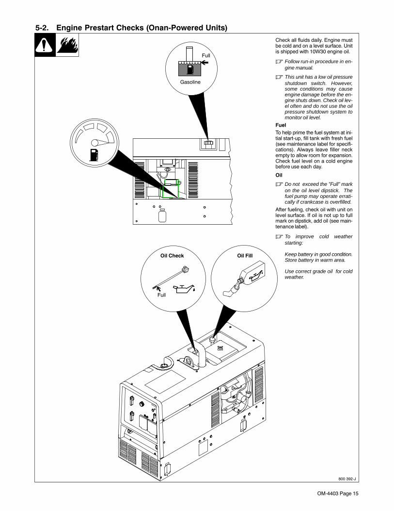
Check all fluids daily. Engine mustbe cold and on a level surface. Unitis shipped with 10W30 engine oil.
� Follow run-in procedure in en-gine manual.
� This unit has a low oil pressureshutdown switch. However,some conditions may causeengine damage before the en-gine shuts down. Check oil lev-el often and do not use the oilpressure shutdown system tomonitor oil level.
FuelTo help prime the fuel system at ini-tial start-up, fill tank with fresh fuel(see maintenance label for specifi-cations). Always leave filler neckempty to allow room for expansion.Check fuel level on a cold enginebefore use each day.
Oil
� Do not exceed the ”Full” markon the oil level dipstick. Thefuel pump may operate errati-cally if crankcase is overfilled.
After fueling, check oil with unit onlevel surface. If oil is not up to fullmark on dipstick, add oil (see main-tenance label).
� To improve cold weatherstarting:
Keep battery in good condition.Store battery in warm area.
Use correct grade oil for coldweather.
Oil Check Oil Fill

OM-4403 Page 16
5-3. Engine Prestart Checks (Kohler-Powered Units)
Ref. 801 188-D / Ref. 801 221-A
Check all fluids daily. Engine mustbe cold and on a level surface. Unitis shipped with 10W30 engine oil.
� Follow run-in procedure in en-gine manual.
� This unit has a low oil pressureshutdown switch. However,some conditions may causeengine damage before the en-gine shuts down. Check oil lev-el often and do not use the oilpressure shutdown system tomonitor oil level.
FuelTo help prime the fuel system at ini-tial start-up, fill tank with fresh fuel(see maintenance label for specifi-cations). Always leave filler neckempty to allow room for expansion.Check fuel level on a cold enginebefore use each day.
Oil
� Do not exceed the ”Full” markon the oil level dipstick. Thefuel pump may operate errati-cally if crankcase is overfilled.
After fueling, check oil with unit onlevel surface. If oil is not up to fullmark on dipstick, add oil (see main-tenance label).
� To improve cold weatherstarting:
Keep battery in good condition.Store battery in warm area.
Use correct grade oil for coldweather.
Full
Full
Gasoline

OM-4403 Page 17
5-4. Activating The Dry Charge Battery (If Applicable)
Remove battery from unit.
1 Eye Protection − SafetyGlasses Or Face Shield
2 Rubber Gloves
3 Vent Caps
4 Sulfuric Acid Electrolyte(1.265 Specific Gravity)
5 Well
Fill each cell with electrolyte tobottom of well (maximum).
� Do not overfill battery cells.
Wait ten minutes and check electro-lyte level. If necessary, add electro-lyte to raise to proper level. Reins-tall vent caps.
6 Battery Charger
� Read and follow all instruc-tions supplied with batterycharger.
Charge battery for 12 minutes at 30amperes or 30 minutes at 5 am-peres. Disconnect charging cablesand install battery.
� When electrolyte is low, addonly distilled water to cells tomaintain proper level.
3
Tools Needed:
1
2
4
6
30 A For 12 Minutes
5 A For 30 Minutes
OR
+
−
5
drybatt1 1/98 − S-0886
rubbergloves
glasses

OM-4403 Page 18
5-5. Connecting the Battery
Ref. 800 394-C / Ref. 200 017-A / Ref. S-0756-D3/8, 1/2 in
Tools Needed:
+ −
� Connect negative (−)cable last.
5-6. Installing Exhaust Pipe
801 681 / Ref. 200 017-A
� Engine backfire can cause se-vere burns or other injuries. Donot point exhaust pipe towardcontrol panel. Keep away fromexhaust outlet.
� Point exhaust pipe in desired di-rection but always away from frontpanel and direction of travel.
� Be sure to tighten exhaust clampnuts.
Tools Needed:
1/2 in

OM-4403 Page 19
5-7. Connecting to Weld Output Terminals
800 396-B / Ref. 200 017-A
� See Section 6 for examples oftypical weld connections andcontrol settings.
1 Work Weld Output Terminal
2 Electrode Weld Output Terminal
Connect work cable to Work terminal.
Connect electrode holder cable orelectrode weld cable to Electrode ter-minal for Stick and MIG welding.
Connect torch cable to Electrode ter-minal for TIG welding.
Use Process Selector switch toselect type of weld output (seeSection 6-1).
� See Sections 6-2 thru 6-4 for typi-cal process connections andcontrol settings.
Tools Needed:3/4 in
1 2
5-8. Selecting Weld Cable Sizes*
Weld Cable Size** and Total Cable (Copper) Length in Weld CircuitNot Exceeding***
100 ft (30 m) or Less 150 ft(45 m)
200 ft(60 m)
250 ft(70 m)
300 ft(90 m)
350 ft(105 m)
400 ft(120 m)
Weld OutputTerminals
� Turn off power beforeconnecting to weld out-put terminals.
� Do not use worn, dam-aged, undersized, orpoorly spliced cables.
WeldingAmperes
10 − 60%DutyCycle
60 − 100%DutyCycle
10 − 100% Duty Cycle
100 4 (20) 4 (20) 4 (20) 3 (30) 2 (35) 1 (50) 1/0 (60) 1/0 (60)
150 3 (30) 3 (30) 2 (35) 1 (50) 1/0 (60) 2/0 (70) 3/0 (95) 3/0 (95)
200 3 (30) 2 (35) 1 (50) 1/0 (60) 2/0 (70) 3/0 (95) 4/0 (120) 4/0 (120)
250 2 (35) 1 (50) 1/0 (60) 2/0 (70) 3/0 (95) 4/0 (120)2 ea. 2/0(2x70)
2 ea. 2/0(2x70)
300 1 (50) 1/0 (60) 2/0 (70) 3/0 (95) 4/0 (120)2 ea. 2/0(2x70)
2 ea. 3/0(2x95)
2 ea. 3/0(2x95)
350 1/0 (60) 2/0 (70) 3/0 (95) 4/0 (120)2 ea. 2/0(2x70)
2 ea. 3/0(2x95)
2 ea. 3/0(2x95)
2 ea. 4/0(2x120)
400 1/0 (60) 2/0 (70) 3/0 (95) 4/0 (120)2 ea. 2/0(2x70)
2 ea. 3/0(2x95)
2 ea. 4/0(2x120)
2 ea. 4/0(2x120)
500 2/0 (70) 3/0 (95) 4/0 (120)2 ea. 2/0(2x70)
2 ea. 3/0(2x95)
2 ea. 4/0(2x120)
3 ea. 3/0(3x95)
3 ea. 3/0(3x95)
* This chart is a general guideline and may not suit all applications. If cable overheating occurs, use next size larger cable.
**Weld cable size (AWG) is based on either a 4 volts or less drop or a current density of at least 300 circular mils per ampere.( ) = mm2 for metric use S-0007-F
***For distances longer than those shown in this guide, call a factory applications representative at 920-735-4505.

OM-4403 Page 20
SECTION 6 − OPERATING THE WELDING GENERATOR
5
4
1 32
6-1. Front Panel Controls
Ref. 200 017-A
1 Engine Control SwitchUse switch to start engine, select speed, andstop engine. In Run/Idle position, engine runsat idle speed at no load, and weld/power speedunder load. In Run position, engine runs atweld/power speed.
� Place switch in Run position to operatemost MIG equipment.
2 Engine Choke ControlUse control to change engine air-fuel mix.To Start: pull out choke and turn Engine Con-trol switch to Start position. Release switchand slowly push choke in when engine starts.
� If the engine does not start, let enginecome to a complete stop before attempt-ing restart.
To Stop: turn Engine Control switch to Off
position.
3 Engine Hour Meter
4 Weld Process Selector Switch
� Do not switch under load.
Use switch to select type of weld output.
Use a positive (+) position for Direct CurrentElectrode Positive (DCEP) and a negative (−)position for Direct Current Electrode Negative.Use AC position for alternating current.
5 Coarse Range Switch
� Do not switch under load.
Use switch to select weld amperage rangewhen Weld Process Selector switch is in Stick/Tig position, or voltage range when switch is inWire position.
� For best arc starts and when using weldand generator power together, use a lowCoarse Range setting with the Fine con-trol set at 7 or higher.
6 Fine ControlUse control to select weld amperage (Stick/Tig) or voltage (Wire) within the range selectedby the Coarse Range switch. Control may beadjusted while welding.Set control at 10 for maximum generator pow-er.
Weld output would be about 124 A DC basedon control settings shown (80% of 60 to 140A). Settings shown are typical for welding witha 7018 (1/8) electrode.
� See Sections 6-2 thru 6-4 for typical pro-cess connections and control settings.
6
Shown with optionalreceptacle covers.

OM-4403 Page 21
6-2. Typical Stick Welding Connections And Control Settings
Ref. 800 395 / 200 017-A / 087 985-A / Ref. S-0653
� Stop engine.
� This section provides general guide-lines and may not suit all applications.
� The control panel shows the typicalsettings for welding with a 7018 (1/8 in)electrode. Consult the amperageselection tables below if welding withother electrodes.
1 Work Clamp
2 Electrode Holder
Connect Work cable to Work terminal andElectrode holder cable to Electrode termi-nal on welding generator.
� Be sure to use the correct size weldcables (see Section 5-8).
� For best performance, set the CoarseRange switch to the lowest range thatcovers the desired weld amperage.Use the Fine control to select the de-sired amperage within the range se-lected. When properly set, the Finecontrol is normally set at 7 or higher.
Typical Settings For 7018 (1/8 in)Electrode:
� Set Weld Process Selector switch to+ Stick position.
� Set Coarse Range switch to 60-140(1/8”) position.
� Set Fine control at 7 or higher forbest results.
1
2
ELE
CT
RO
DE
DC
*
AC
PO
SIT
ION
PE
NE
TR
AT
ION
US
AG
EMIN. PREP, ROUGH
HIGH SPATTER
GENERAL
SMOOTH, EASY,FAST
LOW HYDROGEN,STRONG
SMOOTH, EASY,FASTER
CAST IRON
STAINLESS
DEEP
DEEP
LOW
MED
LOW
LOW
LOW
LOW
ALL
ALL
ALL
ALL
ALL
FLATHORIZFILLET
ALL
ALL
EP
EP
EP,EN
EP,EN
EP
EP,EN
EP
EP
6010
6011
6013
7014
7018
7024
NI-CL
308L
*EP = ELECTRODE POSITIVE (REVERSE POLARITY) EN = ELECTRODE NEGATIVE (STRAIGHT POLARITY)
3/321/8
5/323/167/32
1/41/165/643/32
1/85/323/167/32
1/43/32
1/85/323/167/32
1/43/32
1/85/323/167/32
1/43/32
1/85/323/167/32
1/43/32
1/85/323/163/32
1/85/32
6010&
6011
6013
7014
7018
7024
Ni-Cl
308L
50 100
150
200
250
300
350
400
450ELE
CT
RO
DE
AM
PE
RA
GE
RA
NG
E
DIA
ME
TE
R
Electrode Selection Tables
Tools Needed:
For best arc starts and bestresults using weld and generatorpower together, use a lowCoarse Range setting and theFine control set at 7 or higher.
3/4 in
Typical Settings For 7018 (1/8 in) Electrode

OM-4403 Page 22
6-3. Typical MIG Welding Connections And Settings
A. Solid Wire Applications
802 766 / 200 017-A
� Stop engine.
� This section provides general guide-lines and may not suit all ap-plications.
� The control panel shows the typicalsettings for welding with .035(ER70S-3) solid wire. Use Argon-based shielding gas.
1 Work Clamp
2 Wire Feeder
3 MIG Gun
4 Gun Trigger Plug
5 Voltage Sensing Clamp
6 Gas Cylinder:
75/25 Argon-Based Gas for ShortCircuit Transfer
80% Argon (Or Higher) For SprayTransfer
7 Gas Hose
Connect work cable to welding generatorWork terminal. Connect cable from wirefeeder to cable from welding generatorElectrode terminal.
� Be sure to use the correct size weldcables (see Section 5-8).
Loosen MIG gun securing knob. Insertgun end through opening in feeder andposition as close as possible to drive rollswithout touching. Tighten knob.
See wire feeder manual for wire thread-ing procedure.
Insert gun trigger plug (item 4) intomatching receptacle and tightenthreaded collar.
Connect gas hose from feeder to regula-tor on cylinder.
Typical Control Settings For ShortCircuit Transfer Using .035 (ER70S-3)Solid Wire And 75/25 Argon-BasedGas:
� Set Weld Process Selector switchto Wire + (DCEP) position.
� Set Coarse Range switch to Wire/Low Range (17-22 volts) position.
� Set Fine Control to obtain minimumspatter.
� Set wire feed speed between150-300 ipm.
Typical Control Settings For SprayTransfer Using .035 (ER70S-3) SolidWire And 80% Or Higher Argon-Based Gas:
� Set Weld Process Selector switchto Wire + position.
� Set Coarse Range switch to Wire/High Range (20-28 volts) position.
� Set wire feed speed between320-500 ipm.
� Set Fine control to 3 and increasefor longer arc length.
Tools Needed:
Typical Control Settings For .035 (ER70S-3)Solid Wire − Short Circuit Transfer
3/4 in
Note Coarse Range,Fine Control, and
Weld Process switchsettings.
Quick connector
6
3
2
5
1
4
7
Work

OM-4403 Page 23
B. Self-Shielded Flux Core Wire Applications
802 766 / 200 017-A
� Stop engine.
� This section provides generalguidelines and may not suit allapplications.
� The control panel shows the typi-cal settings for welding with .045(71T-11) self-shielded flux corewire.
1 Work Clamp
2 Wire Feeder
3 MIG Gun
4 Gun Trigger Plug
5 Voltage Sensing Clamp
Connect work cable to welding gen-erator Work terminal. Connect cablefrom wire feeder to cable from weld-ing generator Electrode terminal.
� Be sure to use the correct sizeweld cables (see Section 5-8).
Loosen MIG gun securing knob. In-sert gun end through opening in feed-er and position as close as possibleto drive rolls without touching. Tight-en knob.
See wire feeder manual for wirethreading procedure.
Insert gun trigger plug (item 4) intomatching receptacle and tightenthreaded collar.
Typical Control Settings Using.045 (71T-11) Self-Shielded FluxCore Wire :
� Set Weld Process Selectorswitch to Wire − position(DCEN).
� Set Coarse Range switch toWire/Low Range (17-22 volts)position.
� Set Fine Control near minimumsetting.
� Set wire feed speed between125-200 ipm.
� Do a test weld. To increase arclength, increase Fine Controlsetting. To shorten arc length,reduce fine control setting or in-crease wire feed speed.
Tools Needed:
Typical Control Settings For .045 (71T-11) Self-Shielded Flux Core Wire
3/4 in
Note Coarse Range,Fine Control, and
Weld Process switchsettings.
Quick connector
3
2
5
1
4
Work

OM-4403 Page 24
6-4. Typical MIG Connections And Settings Using Weld Control And Spoolgun
802 750 / 200 017-A
� This section provides general guide-lines and may not suit all applications.
1 Weld Control
2 Spoolgun
3 Optional Contactor (Recommended)
4 Reed Switch
5 Weld Cable (Customer-Supplied)
6 Weld Control Weld Terminal
7 Weld Power Cable From Spoolgun
8 Work Clamp
9 Gas Hose
10 Argon Cylinder
11 Trigger Control Cord
12 Input Power Cord
� Be sure to use the correct size weldcables (see Section 5-8).
Route weld cable from welding generatorElectrode terminal through reed switch tounused contactor terminal. Connect weldcable from spoolgun to weld control weld ter-minal (item 6).
Connect work cable to welding generatorWork terminal.
Insert trigger control plug (item 11) into weldcontrol receptacle. Tighten threaded collar.
Connect ac power cord (item 12) to 120 voltac receptacle on welding generator.
Connect gas hose from spoolgun to regula-tor on Argon bottle.
Reinstall weld control wrapper.
Typical Settings For 4043 (.035) Aluminum On 1/8 in Material:
� Set Weld Process Selector switch toWire + (DCEP) position.
� Set Coarse Range switch to Wire/Low(17-22 volts) position.
� Set Fine Control to desired voltage(arc length). Start with a low voltagesetting (about 4) to prevent burnback.
� Set wire feed speed between 240-270ipm. For 1/4 in. and thicker materials,set Coarse Range switch to Wire/Highand Fine Control to 6. Increase/de-crease Fine Control setting to in-crease/decrease arc length.
Plug and sensing lead notused in this application.
1
2
5
6
8
9
10
Left Side View
4 5 7
3
Work
Note Coarse Range and WeldProcess switch settings.
11
12
6
Tools Needed:
Connect to unusedcontactor terminal.
3/4 in
Typical Settings For 4043 (.035)Aluminum On 1/8 in Material:

OM-4403 Page 25
SECTION 7 − OPERATING AUXILIARY EQUIPMENT7-1. Standard Receptacles
Ref. 200 017-A
� If unit does not have GFCI re-ceptacles, use GFCI-protectedextension cord.
� Generator power decreases asweld current increases.
Set Fine Control R1 at 10 for fullgenerator power.
1 240 V 50 A AC Receptacle RC1
RC1 supplies 60 Hz single-phasepower at weld/power speed. Maxi-mum output is 10 kVA/kW.
2 120 V 20 A AC Duplex Recep-tacle RC2
3 120 V 20 A AC Duplex Recep-tacle RC3
RC2 and RC3 supply 60 Hz single-phase power at weld/power speed.Maximum output from RC2 or RC3 is2.4 kVA/kW.
4 Circuit Breakers CB1 and CB2
CB1 and CB2 protect RC1 from over-load. If CB1 or CB2 opens, RC1 andone of the 120 volt receptacles doesnot work. 120 volts may still be pres-ent at RC1.
� Power is still present at the 240volt receptacle when only onecircuit breaker trips.
Unplug power cord before at-tempting to service accesso-ries or tools.
5 Circuit Breaker CB3
6 Circuit Breaker CB4
CB3 protects RC2 and CB4 protectsRC3 from overload. If a circuit break-er opens, the receptacle does notwork.
� Press button to reset circuitbreaker. If breaker continues toopen, contact FactoryAuthorized Service Agent.
Combined output of all receptacleslimited to 10 kVA/kW rating of the gen-erator.
EXAMPLE: If 20 A is drawn fromeach 120 V duplex receptacle, only21 A is available at the 240Vreceptacle:
2 x (120 V x 20 A) + (240 V x 21 A) =10 kVA/kW
4 51
2 3
6

OM-4403 Page 26
7-2. Optional Generator Power Receptacles
� If unit does not have GFCI recep-tacles, use GFCI-protected exten-sion cord.
� Generator power decreases as weldcurrent increases.
Set Fine Control R1 at 10 for full genera-tor power.
Combined output of all receptacles limited to10 kVA/kW rating of the generator.
CSA Receptacle Option
Receptacles supply 60 Hz single-phasepower at weld/power speed. Receptaclesand generator power output are the same ason standard unit (see Section 7-1).
1 Circuit Breaker CB1
CB1 protects RC1 from overload. If CB1opens, the receptacles do not work. Pushswitch up to reset breaker. Circuit breakerprotection for remaining receptacles is thesame as on standard unit (see Section 7-1).
GFCI Receptacle Option
2 120 V 20 A AC GFCI ReceptaclesGFCI-2 and GFCI-3
GFCI2 and GFCI3 supply 60 Hz single-phase power at weld/power speed. Maxi-mum output from GFCI-2 or GFCI-3 is 2.4kVA/kW. Circuit breaker protection is thesame as standard receptacles.
If a ground fault is detected, the GFCI Resetbutton pops out and the circuit opens to dis-connect the faulty equipment. Check fordamaged tools, cords, plugs, etc. con-nected to the receptacle. Press button to re-set receptacle and resume operation.
� Power is still present at the 240 voltreceptacle when only one circuitbreaker trips.
Unplug power cord before attempt-ing to service accessories or tools.
� At least once a month, run engine atweld/power speed and press Test but-ton to verify GFCI is working properly.
South African And Australian Recepta-cle Options
3 240 V 16 A AC South African Recep-tacles RC1, RC2, and RC3
4 240 V 15 A AC Australian Recep-tacles RC1, RC2, and RC3
Receptacles supply 60 Hz single-phasepower at weld/power speed. Maximum out-put from each receptacle is 3.6 kVA/kW.
5 Circuit Breakers CB1, CB2, CB3
CB1, CB2, and CB3 protect RC1, RC2, andRC3 from overload. If a circuit breakeropens, the receptacle does not work.
6 Circuit Breaker CB4
CB4 protects all the receptacles from over-load. If CB4 opens, none of the receptacleswork.
� Press button to reset circuit breaker. Ifbreaker continues to open, contact Fac-tory Authorized Service Agent.
2
3
5
6
4
5
6
Ref. 205 903 / 200 017-A / Ref. 172 782-B / Ref. 172 113-A
1

OM-4403 Page 27
7-3. Wiring Optional 240 Volt Plug
120 813-D
The plug can be wired for a 240 V,2-wire load or a 120/240V, 3-wireload. See circuit diagram.
1 Plug Wired for 120/240 V,3-Wire Load
When wired for 120 V loads, eachduplex receptacle shares a loadwith one half of 240 V receptacle.
2 Plug Wired for 240 V, 2-WireLoad
3 Neutral (Silver) Terminal
4 Load 1 (Brass)Terminal
5 Load 2 (Brass) Terminal
6 Ground (Green) Terminal
7 Amperes Available Using120/240 V Plug
1
2
34
56
3
4
5
6
240V
240V
120V120V
*One 240 V load or two 120 V loads.
7
Current Available in Amperes
240 VReceptacle*
Each 120 V DuplexReceptacle
V x A = Watts
4237322722
05101520
Tools Needed:
Notes
Work like a Pro!
Pros weld and cut
safely. Read the
safety rules at
the beginning
of this manual.

OM-4403 Page 28
SECTION 8 − MAINTENANCE (ONAN-POWERED UNITS)
8-1. Routine Maintenance (Onan-Powered Units)
Follow the storage procedure in the engine owner’s manual if the unit will not be used for anextended period.
Note
Recycleenginefluids.
� Stop engine before maintaining.
� See Engine Manual and Maintenance Label forimportant start-up, service, and storage informa-tion. Service engine more often if used in severeconditions.
* To be done by Factory Authorized Service Agent.
Every 8 h
Wipe up spills.Check fluid levels.See Section 5-2.
Every 20 h Every 25 h
Check and cleanspark arrestor screen.See Section 5-2.
Service aircleaner wrapper(foam element).See Section 8-3.
Every 50 h
Clean andtighten weldterminals.
Every 100 h
Clean cooling system.See Engine Manual.
Change oil. SeeSection 8-5 andmaintenance label.
Clean andtighten batteryconnections.
Service air cleaner ele-ment. See Section 8-3.
Every 200 h
Replace fuelfilter. SeeSection 8-5.
Change oil filter. SeeSection 8-5 andmaintenance label.
Checksparkplugs.
Replaceunreadablelabels.

OM-4403 Page 29
Every 500 h
Repair orreplace crackedcables.
Service welding generatorbrushes and slip rings. Servicemore often in dirty conditions.*
Checkvalveclearance.*
Every 1000 h
Blow out or vacuuminside. During heavyservice, clean monthly.
OR
8-2. Maintenance Label (Onan-Powered Units)

OM-4403 Page 30
8-3. Servicing Air Cleaner (Onan-Powered Units)
aircleaner5 1/97 − 803 070 / Ref. 200 017-A / S-0759
� Stop engine.
� Do not run engine without aircleaner or with dirty element.
1 Wrapper (Foam Element)
Wash wrapper with soap and watersolution. Allow wrapper to air drycompletely.
Spread 1 tablespoon SAE 30 oilevenly into wrapper. Squeeze outexcess oil.
2 Element
Replace element if dirty, oily, ordamaged.
1
2
8-4. Overload Protection (Onan-Powered Units)
802 921-C
� Stop engine. Disconnectnegative (−) battery cable.
1 Fuse F1 (See Parts List)
F1 protects the weld excitationwinding from overload. If F1 opens,weld output stops or is low.
2 Fuse F2 (See Parts List)
F2 protects the generator powerexcitation winding from overload. IfF2 opens, generator power outputstops or is low.
3 Fuse F6 (See Parts List)
F6 protects the engine wiring sys-tem from overload. If F6 opens,engine will not crank.
Replace any open fuses. Reinstallcover before operating.
� If a fuse opens, it usually indi-cates a more serious problemexists. Contact a Factory Au-thorized Service Agent.
3/8 in
2
3
Tools Needed:
1

OM-4403 Page 31
8-5. Changing Engine Oil, Oil Filter, and Fuel Filter (Onan-Powered Units)
802 921-A / S-0842
� Stop engine and let cool.
1 Oil Drain Valve
2 1/2 ID x 12 in Hose
3 Oil Filter
Change engine oil and filter accord-ing to engine owner’s manual.
� Close valve and valve capbefore adding oil andrunning engine.
Fill crankcase with new oil to fullmark on dipstick (see Section 8-2).
4 Fuel Filter
5 Fuel Line
Replace line if cracked or worn.Install new filter. Wipe up any spilledfuel.
Start engine, and check for fuelleaks.
� Stop engine, tighten connec-tions as necessary, and wipeup fuel.
4
5
1
2
Tools Needed:
3
Full
Oil Check Oil Fill

OM-4403 Page 32
8-6. Adjusting Engine Speed (Onan-Powered Units)
800 392-J / 802 457
After tuning engine, check enginespeeds with a tachometer (seetable). If necessary, adjust speedsas follows:
Start engine and run until warm.
Remove wrapper to access speedadjustments.
Idle Speed Adjustment
Move Engine Control switch toRun/Idle position.
1 Throttle Solenoid
2 Mounting Screws
3 Idle Speed Screw
Loosen mounting screws. Adjustsolenoid position so engine runs atidle speed. If necessary, back outidle speed screw so solenoid canbe moved to correct position. Tight-en mounting screws. Be sure sole-noid linkage works smoothly.
Turn idle speed screw for fineadjustments.
Weld/Power Speed Adjustment
Move Engine Control switch to Runposition.
4 Jam Nut
5 Lock Nut
6 Weld/Power SpeedAdjustment Screw
Loosen jam nut and lock nut. Turnadjustment screw until engine runsat weld/power speed. Tighten jamnut, and then tighten lock nut.
� Stop engine.
Reinstall wrapper.
2200 ± 100 rpm
3700 ± 50 rpm
8 mm
Tools Needed:
1
3
2
4
56
10 mm

OM-4403 Page 33
8-7. Servicing Optional Spark Arrestor (Onan-Powered Units)
Ref. 801 682-A / Ref. 183 175−A
� Stop engine and let cool.
1 Spark Arrestor Screen
Clean and inspect screen. Replacespark arrestor if screen wires arebroken or missing.
1/4 in
1
Tools Needed:
SECTION 9 − MAINTENANCE − (KOHLER-POWERED UNITS)
9-1. Maintenance Label (Kohler-Powered Units)

OM-4403 Page 34
9-2. Routine Maintenance (Kohler-Powered Units)
Follow the storage procedure in the engine owner’s manual if the unit will not be used for anextended period.
Note
Recycleenginefluids.
� Stop engine before maintaining.
� See Engine Manual and Maintenance Label for impor-tant start-up, service, and storage information. Ser-vice engine more often if used in severe conditions.
* To be done by Factory Authorized Service Agent.
Every 8 h
Wipe up spills. Check fluid levels.See Section 5-3.
Every 20 h Every 25 h
Check and clean optionalspark arrestor screen. SeeSection 9-7.
Service air cleanerwrapper (foam element).See Section 9-3.
Every 50 h
Clean and tighten weldterminals.
Every 100 h
Change oil. See Section 9-4and maintenance label.
Check air cleaner element.See Section 9-3.
Clean and tighten batteryconnections.
Clean cooling system. SeeEngine Manual.
Every 200 h
Replace fuel filter. SeeSection 9-4.
Change oil filter. See Section9-4 and maintenance label.
Replace unreadable labels.Check spark plugs.
Every 500 h
Repair or replace crackedcables.
Service welding generatorbrushes and slip rings. Servicemore often in dirty conditions.*
Every 1000 h
Blow out or vacuum inside.During heavy service, cleanmonthly.
OR

OM-4403 Page 35
9-3. Servicing Air Cleaner (Kohler-Powered Units)
aircleaner4 1/97 − 802 822 / Ref. 200 017-A / S-0759
� Stop engine.
� Do not run engine without aircleaner or with dirty element.
1 Wrapper (Foam Element)
Wash wrapper with soap and watersolution. Allow wrapper to air drycompletely.
Spread 1 tablespoon SAE 30 oilevenly into wrapper. Squeeze outexcess oil.
2 Element
Replace element if dirty, oily, ordamaged.
1
2
Notes
Work like a Pro!
Pros weld and cut
safely. Read the
safety rules at
the beginning
of this manual.

OM-4403 Page 36
9-4. Changing Engine Oil, Oil Filter, and Fuel Filter (Kohler-Powered Units)
Ref. 801 188-D / Ref. 200 017-A / 800 395 / S-0842
� Stop engine and let cool.
1 Oil Drain Valve
2 1/2 ID x 12 in Hose
3 Oil Filter
Change engine oil and filter accord-ing to engine owner’s manual.
� Close valve and valve capbefore adding oil andrunning engine.
Fill crankcase with new oil to fullmark on dipstick (see Section 9-1).
4 Fuel Filter
5 Fuel Line
Replace line if cracked or worn.Install new filter. Wipe up any spilledfuel.
Start engine, and check for fuelleaks.
� Stop engine, tighten connec-tions as necessary, and wipeup fuel.
1
2
4
5
Tools Needed:
3
Full

OM-4403 Page 37
9-5. Adjusting Engine Speed (Kohler-Powered Units)
Ref. 801 188-D / 801 209-A
After tuning engine, check enginespeeds with a tachometer (seetable). If necessary, adjust speedsas follows:
Start engine and run until warm.Turn Fine Control to 10.
Remove top cover to access speedadjustments.
Idle Speed Adjustment
Move Engine Control switch toRun/Idle position.
1 Throttle Solenoid
2 Mounting Screws
3 Idle Speed Screw
Loosen mounting screws. Adjustsolenoid position so engine runs atidle speed. If necessary, back outidle speed screw so solenoid canbe moved to correct position. Tight-en mounting screws. Be sure sole-noid linkage works smoothly.
Turn idle speed screw for fine ad-justments.
Weld/Power Speed Adjustment
Move Engine Control switch to Runposition.
4 Weld/Power SpeedAdjustment Nut
5 Lock Nut
Loosen lock nut. Turn adjustmentnut until engine runs at weld/powerspeed. Tighten lock nut.
Reinstall top cover.
� Stop engine.
1/4, 3/8 in
Top View
Tools Needed:
2200 ± 50 rpm
3700 ± 50 rpm
3
5
4
1
2

OM-4403 Page 38
9-6. Overload Protection (Kohler-Powered Units)
Ref. 802 921 / Ref. 801 221-A / Ref. 183 175−A
� Stop engine. Disconnectnegative (−) battery cable.
1 Fuse F1 (See Parts List)
F1 protects the weld excitationwinding from overload. If F1 opens,weld output stops or is low.
2 Fuse F2 (See Parts List)
F2 protects the generator powerexcitation winding from overload. IfF2 opens, generator power outputstops or is low.
3 Fuse F6 (See Parts List)
F6 protects the engine wiring sys-tem from overload. If F6 opens,engine will not crank.
Replace any open fuses. Reinstallcover before operating.
� If a fuse opens, it usually indi-cates a more serious problemexists. Contact a Factory Au-thorized Service Agent.
3/8 in
3
Tools Needed:
2
1
9-7. Servicing Optional Spark Arrestor (Kohler-Powered Units)
Ref. 801 695-A / Ref. 200 017-A
� Stop engine and let cool.
1 Spark Arrestor Screen
Clean and inspect screen. Replacespark arrestor if screen wires arebroken or missing.
1/4 in
Tools Needed:
1

OM-4403 Page 39
SECTION 10 − TROUBLESHOOTING10-1. Welding Troubleshooting
Trouble Remedy
Low or no weld output; generator pow-er output okay at ac receptacles.
Check control settings.
Check weld connections.
Check fuse F1, and replace if open (see Section 8-4 or 9-6).
Have Factory Authorized Service Agent check brushes, slip rings, and integrated rectifiers SR2 andSR3.
No weld output or generator power out-put at ac receptacles.
Be sure all equipment is disconnected from receptacles when starting unit.
Check fuses F1 and F2, and replace if open (see Section 8-4 or 9-6).
Check plug PLG6 connection.
Have Factory Authorized Service Agent check brushes, slip rings, and integrated rectifiers SR2, SR3.
Low weld output. Check fuse F1, and replace if open (see Section 8-4 or 9-6).
Check control settings.
Check engine speed, and adjust if necessary (see Section 8-6 or 9-5).
Service air cleaner according to engine manual.
Have Factory Authorized Service Agent check brushes, slip rings, and integrated rectifiers SR2, SR3.
High weld output. Check control settings.
Check engine speed, and adjust if necessary (see Section 8-6 or 9-5).
Erratic weld output. Check control settings.
Tighten and clean connections to electrode and workpiece.
Use dry, properly-stored electrodes for Stick and TIG welding.
Remove excessive coils from weld cables.
Clean and tighten connections both inside and outside welding generator.
Check engine speed, and adjust if necessary (see Section 8-6 or 9-5).
Have Factory Authorized Service Agent check brushes, slip rings, and integrated rectifiers SR2, SR3.
10-2. Generator Power Troubleshooting
Trouble Remedy
No or low generator power output at acreceptacles; weld output okay
Reset circuit breakers (see Section 7-1 or 7-2).receptacles; weld output okay.
Press optional GFCI receptacle Reset button (see Section 7-2).
Check fuse F2, and replace if open (see Section 8-4 or 9-6).
Check plug PLG6 connection.
Have Factory Authorized Service Agent check brushes, slip rings, and integrated rectifier SR3.
No generator power or weld output. Be sure all equipment is disconnected from receptacles when starting unit.
Check fuses F1 and F2, and replace if open (see Section 8-4 or 9-6).
Check plug PLG6 connection.
Have Factory Authorized Service Agent check brushes, slip rings, and integrated rectifiers SR2 andSR3.

OM-4403 Page 40
Trouble Remedy
Low power output at ac receptacles. Check fuse F2, and replace if open (see Section 8-4 or 9-6).
Increase Fine control R1 setting to max.
High power output at ac receptacles. Check engine speed, and adjust if necessary (see Section 8-6 or 9-5).
Erratic power output at ac receptacles. Check fuel level.
Check engine speed, and adjust if necessary (see Section 8-6 or 9-5).
Check receptacle wiring and connections.
Have Factory Authorized Service Agent check brushes and slip rings.
10-3. Engine Troubleshooting
Trouble Remedy
Engine will not crank. Check fuse F6, and replace if open (see Section 8-4 or 9-6).
Check battery voltage.
Check battery connections and tighten if necessary.
Check plug PLG4 and plug PLG8 connections.
Have Factory Authorized Service Agent check Engine Control switch S2.
Engine will not start. Check fuel level.
Check battery voltage.
Check battery connections and tighten if necessary.
Check oil level (see Section 5-2 or 5-3).
Check low oil pressure shutdown switch (see Parts List for location).
Have Factory Authorized Service Agent check fuel shutoff solenoid FS1 (FS1 optional on Onan-poweredunits).
Engine starts but stops when EngineControl switch returns to Run position
Check oil level.Control switch returns to Run position.
Check and refill crankcase with proper viscosity oil for operating temperature, if necessary.
Check low oil pressure shutdown switch (see Parts List for location).
Engine stopped during normaloperation.
Check fuel level.
Check oil level (see Section 5-2 or 5-3).
Check low oil pressure shutdown switch (see Parts List for location)
Periodically recharge battery (approximately every 3 months).
Replace battery.
Check voltage regulator and connections according to engine manual.
Have Factory Authorized Service Agent check fuel shutoff solenoid FS1 (FS1 optional on Onan-poweredunits).
Battery Discharges between uses. Clean battery, terminals, and posts with baking soda and water solution; rinse with clear water.
Periodically recharge battery (approximately every 3 months).
Replace battery.
Check voltage regulator and connections according to engine manual.
Engine idles but does not come up toweld speed.
Have Factory Authorized Service Agent check auto idle module PC1, and current transformer CT1.

OM-4403 Page 41
Trouble Remedy
Unstable or sluggish engine speeds. Readjust throttle linkage if necessary. Check throttle solenoid TS1 for smooth operation.
Check oil level. Oil level should not exceed Full mark on dipstick. Fuel pump will operate erratically ifcrankcase is overfilled.
Tune-up engine according to engine manual.
Engine does not return to idle speed. Remove weld and generator power loads.
Check throttle linkage for smooth, non-binding operation.
Have Factory Authorized Service Agent check idle module PC1, current transformer CT1, Engine Controlswitch S2, and throttle solenoid TS1.
Notes

OM-4403 Page 42
SECTION 11 − ELECTRICAL DIAGRAMS
Figure 11-1. Circuit Diagram For Welding Generator
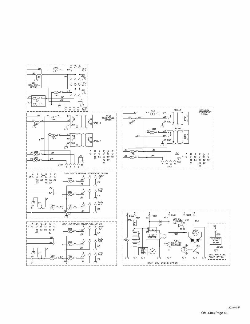
OM-4403 Page 43
202 547-F

OM-4403 Page 44
SECTION 12 − GENERATOR POWER GUIDELINES
The views in this section are intended to be representative of all engine-drivenwelding generators. Your unit may differ from those shown.
NOTE
12-1. Selecting Equipment
gen_pwr 11/02 − Ref. ST-159 730 / ST-800 577
1 Generator Power Receptacles− Neutral Bonded To Frame
2 3-Prong Plug From CaseGrounded Equipment
3 2-Prong Plug From DoubleInsulated Equipment
� Do not use 2-prong plug un-less equipment is double in-sulated.
OR
2
Be sure equipmenthas this symboland/or wording.
3
1
12-2. Grounding Generator To Truck Or Trailer Frame
S-0854
� Always ground generatorframe to vehicle frame to pre-vent electric shock and staticelectricity hazards.
1 Equipment GroundingTerminal (On Front Panel)
2 Grounding Cable (NotSupplied)
3 Metal Vehicle Frame
Connect cable from equipmentground terminal to metal vehicleframe. Use #10 AWG or largerinsulated copper wire.
� If unit does not have GFCI re-ceptacles, use GFCI-pro-tected extension cord.
Electrically bond generatorframe to vehicle frame bymetal-to-metal contact.
GND/PE
3
1
2
� Bed liners, shipping skids, and some runninggear insulate the welding generator from the ve-hicle frame. Always connect a ground wire fromthe generator equipment grounding terminal tobare metal on the vehicle frame as shown.

OM-4403 Page 45
12-3. Grounding When Supplying Building Systems
ST-800 576-B
1 Equipment GroundingTerminal
2 Grounding Cable
Use #10 AWG or larger insulatedcopper wire.
3 Ground Device
� Ground generator to systemearth ground if supplyingpower to a premises (home,shop, farm) wiring system.
GND/PE
1 2
Use ground device as statedin electrical codes.
2 3
12-4. How Much Power Does Equipment Require?
S-0623
1 Resistive Load
A light bulb is a resistive load andrequires a constant amount of power.
2 Non-Resistive Load
Equipment with a motor is a non-re-sistive load and requires approxi-mately six times more power whilestarting the motor than when running(see Section 12-8).
3 Rating Data
Rating shows volts and amperes, orwatts required to run equipment.
VOLTS 1154.560
AMPSHz1
2
3
3
EXAMPLE 1: If a drill uses 4.5 amperes at 115 volts, calculate its running powerrequirement in watts.
4.5 A x 115 V = 520 W
The load applied by the drill is 520 watts.
EXAMPLE 2: If three 200 watt flood lamps are used with the drill from Example 1,add the individual loads to calculate total load.
The total load applied by the three flood lamps and drill is 1120 watts.
(200 W + 200 W + 200 W) + 520 W = 1120 W
AMPERES x VOLTS = WATTS

OM-4403 Page 46
12-5. Approximate Power Requirements For Industrial Motors
Industrial Motors Rating Starting Watts Running Watts
Split Phase 1/8 HP 800 300
1/6 HP 1225 500
1/4 HP 1600 600
1/3 HP 2100 700
1/2 HP 3175 875
Capacitor Start-Induction Run 1/3 HP 2020 720
1/2 HP 3075 975
3/4 HP 4500 1400
1 HP 6100 1600
1-1/2 HP 8200 2200
2 HP 10550 2850
3 HP 15900 3900
5 HP 23300 6800
Capacitor Start-Capacitor Run 1-1/2 HP 8100 2000
5 HP 23300 6000
7-1/2 HP 35000 8000
10 HP 46700 10700
Fan Duty 1/8 HP 1000 400
1/6 HP 1400 550
1/4 HP 1850 650
1/3 HP 2400 800
1/2 HP 3500 1100
12-6. Approximate Power Requirements For Farm/Home Equipment
Farm/Home Equipment Rating Starting Watts Running Watts
Stock Tank De-Icer 1000 1000
Grain Cleaner 1/4 HP 1650 650
Portable Conveyor 1/2 HP 3400 1000
Grain Elevator 3/4 HP 4400 1400
Milk Cooler 2900 1100
Milker (Vacuum Pump) 2 HP 10500 2800
FARM DUTY MOTORS 1/3 HP 1720 720
Std. (e.g. Conveyors, 1/2 HP 2575 975
Feed Augers, Air 3/4 HP 4500 1400
Compressors) 1 HP 6100 1600
1-1/2 HP 8200 2200
2 HP 10550 2850
3 HP 15900 3900
5 HP 23300 6800
High Torque (e.g. Barn 1-1/2 HP 8100 2000
Cleaners, Silo Unloaders, 5 HP 23300 6000
Silo Hoists, Bunk Feeders) 7-1/2 HP 35000 8000
10 HP 46700 10700
3-1/2 cu. ft. Mixer 1/2 HP 3300 1000
High Pressure 1.8 Gal/Min 500 PSI 3150 950
Washer 2 gal/min 550 PSI 4500 1400
2 gal/min 700 PSI 6100 1600
Refrigerator or Freezer 3100 800
Shallow Well Pump 1/3 HP 2150 750
1/2 HP 3100 1000
Sump Pump 1/3 HP 2100 800
1/2 HP 3200 1050

OM-4403 Page 47
12-7. Approximate Power Requirements For Contractor EquipmentContractor Rating Starting Watts Running Watts
Hand Drill 1/4 in 350 350
3/8 in 400 400
1/2 in 600 600
Circular Saw 6-1/2 in 500 500
7-1/4 in 900 900
8-1/4 in 1400 1400
Table Saw 9 in 4500 1500
10 in 6300 1800
Band Saw 14 in 2500 1100
Bench Grinder 6 in 1720 720
8 in 3900 1400
10 in 5200 1600
Air Compressor 1/2 HP 3000 1000
1 HP 6000 1500
1-1/2 HP 8200 2200
2 HP 10500 2800
Electric Chain Saw 1-1/2 HP, 12 in 1100 1100
2 HP, 14 in 1100 1100
Electric Trimmer Standard 9 in 350 350
Heavy Duty 12 in 500 500
Electric Cultivator 1/3 HP 2100 700
Elec. Hedge Trimmer 18 in 400 400
Flood Lights HID 125 100
Metal Halide 313 250
Mercury 1000
Sodium 1400
Vapor 1250 1000
Submersible Pump 400 gph 600 200
Centrifugal Pump 900 gph 900 500
Floor Polisher 3/4 HP, 16 in 4500 1400
1 HP, 20 in 6100 1600
High Pressure Washer 1/2 HP 3150 950
3/4 HP 4500 1400
1 HP 6100 1600
55 gal Drum Mixer 1/4 HP 1900 700
Wet & Dry Vac 1.7 HP 900 900
2-1/2 HP 1300 1300

OM-4403 Page 48
12-8. Power Required To Start Motor
S-0624
1 Motor Start Code
2 Running Amperage
3 Motor HP
4 Motor Voltage
To find starting amperage:
Step 1: Find code and use table tofind kVA/HP. If code is not listed,multiply running amperage by six tofind starting amperage.
Step 2: Find Motor HP and Volts.
Step 3: Determine starting amper-age (see example).
Welding generator amperage out-put must be at least twice themotor’s running amperage.
VOLTS AMPS
HP
230 2.5
1/4HzPHASE
CODE 601
M
AC MOTOR1
2
3
4
Single-Phase Induction Motor Starting Requirements
Motor StartCode G H J K L M N P
KVA/HP 6.3 7.1 8.0 9.0 10.0 11.2 12.5 14.0
EXAMPLE: Calculate the starting amperage required for a 230 V, 1/4HP motor with a motor start code of M.
Starting the motor requires 12.2 amperes.11.2 x 1/4 x 1000
230= 12.2 A
kVA/HP x HP x 1000
VOLTS= STARTING AMPERAGE
Volts = 230 HP = 1/4 Using Table, Code M results in kVA/HP = 11.2
12-9. How Much Power Can Generator Supply?
Ref. ST-800 396-A / S-0625
1 Limit Load To 90% OfGenerator Output
Always start non-resistive (motor)loads in order from largest to small-est, and add resistive loads last.
2 5 Second Rule
If motor does not start within 5seconds, turn off power to preventmotor damage. Motor requiresmore power than generator cansupply.
1
2

OM-4403 Page 49
12-10. Typical Connections To Supply Standby Power
� Have only qualified persons performthese connections according to allapplicable codes and safety practic-es.
� Properly install and ground thisequipment according to its Owner’sManual and national, state, and localcodes.
� Customer-supplied equipment is re-quired if generator will supply standbypower during emergencies or power out-ages.
1 Utility Electrical Service
2 Transfer Switch (Double-Throw)
Switch transfers the electrical load fromelectric utility service to the generator. Trans-fer load back to electric utility when service isrestored.
Install correct switch (customer-supplied).Switch rating must be same as or greaterthan the branch overcurrent protection.
3 Fused Disconnect Switch
Install correct switch (customer-supplied) ifrequired by electrical code.
4 Welding Generator Output
Generator output voltage and wiring must beconsistent with regular (utility) system volt-age and wiring.
Connect generator with temporary or perma-nent wiring suitable for the installation.
Turn off or unplug all equipment connected togenerator before starting or stopping engine.When starting or stopping, the engine haslow speed which causes low voltage andfrequency.
5 Essential Loads
Generator output may not meet the electricalrequirements of the premises. If generatordoes not produce enough output to meet allrequirements, connect only essential loads(pumps, freezers, heaters, etc. − See Sec-tion 12-4).
� Properly install and ground this equipment according toits Owner’s Manual and national, state, and local codes.
Transfer Switch
EssentialLoads
FusedDisconnect
Switch(If Required)
UtilityElectricalService
1 2 3 4
5
WeldingGenerator
Output
Notes
Work like a Pro!
Pros weld and cut
safely. Read the
safety rules at
the beginning
of this manual.

OM-4403 Page 50
12-11. Selecting Extension Cord (Use Shortest Cord Possible)
Cord Lengths for 120 Volt Loads
� If unit does not have GFCI receptacles, use GFCI-protected extension cord.
Maximum Allowable Cord Length in ft (m) for Conductor Size (AWG)*
Current (Amperes) Load (Watts) 4 6 8 10 12 14
5 600 350 (106) 225 (68) 137 (42) 100 (30)
7 840 400 (122) 250 (76) 150 (46) 100 (30) 62 (19)
10 1200 400 (122) 275 (84) 175 (53) 112 (34) 62 (19) 50 (15)
15 1800 300 (91) 175 (53) 112 (34) 75 (23) 37 (11) 30 (9)
20 2400 225 (68) 137 (42) 87 (26) 50 (15) 30 (9)
25 3000 175 (53) 112 (34) 62 (19) 37 (11)
30 3600 150 (46) 87 (26) 50 (15) 37 (11)
35 4200 125 (38) 75 (23) 50 (15)
40 4800 112 (34) 62 (19) 37 (11)
45 5400 100 (30) 62 (19)
50 6000 87 (26) 50 (15)
*Conductor size is based on maximum 2% voltage drop
Cord Lengths for 240 Volt Loads
� If unit does not have GFCI receptacles, use GFCI-protected extension cord.
Maximum Allowable Cord Length in ft (m) for Conductor Size (AWG)*
Current(Amperes) Load (Watts) 4 6 8 10 12 14
5 1200 700 (213) 450 (137) 225 (84) 200 (61)
7 1680 800 (244) 500 (152) 300 (91) 200 (61) 125 (38)
10 2400 800 (244) 550 (168) 350 (107) 225 (69) 125 (38) 100 (31)
15 3600 600 (183) 350 (107) 225 (69) 150 (46) 75 (23) 60 (18)
20 4800 450 (137) 275 (84) 175 (53) 100 (31) 60 (18)
25 6000 350 (107) 225 (69) 125 (38) 75 (23)
30 7000 300 (91) 175 (53) 100 (31) 75 (23)
35 8400 250 (76) 150 (46) 100 (31)
40 9600 225 (69) 125 (38) 75 (23)
45 10,800 200 (61) 125 (38)
50 12,000 175 (53) 100 (31)
*Conductor size is based on maximum 2% voltage drop

OM-4403 Page 51
SECTION 13 − STICK WELDING (SMAW) GUIDELINES
13-1. Stick Welding Procedure
stick 12/96 − ST-151 593
� Weld current starts whenelectrode touches work-piece.
� Weld current can damageelectronic parts in vehicles.Disconnect both batterycables before welding on avehicle. Place work clamp asclose to the weld as possible.
1 Workpiece
Make sure workpiece is clean be-fore welding.
2 Work Clamp
3 Electrode
A small diameter electrode requiresless current than a large one. Fol-low electrode manufacturer’sinstructions when setting weld am-perage (see Section 13-2).
4 Insulated Electrode Holder
5 Electrode Holder Position
6 Arc Length
Arc length is the distance from theelectrode to the workpiece. A shortarc with correct amperage will givea sharp, crackling sound.
7 Slag
Use a chipping hammer and wirebrush to remove slag. Remove slagand check weld bead before mak-ing another weld pass.
Tools Needed:
1
4
3
5
2
7
6

OM-4403 Page 52
13-2. Electrode and Amperage Selection Chart
Ref. S-087 985-A
3/321/8
5/323/167/32
1/41/165/643/32
1/85/323/167/32
1/43/32
1/85/323/167/32
1/43/32
1/85/323/167/32
1/43/32
1/85/323/167/32
1/43/32
1/85/323/163/32
1/85/32
6010&
6011
6013
7014
7018
7024
Ni-Cl
308L
50 100
150
200
250
300
350
400
450
ELE
CT
RO
DE
DC
*
AC
PO
SIT
ION
PE
NE
TR
AT
ION
US
AG
E
MIN. PREP, ROUGHHIGH SPATTER
GENERAL
SMOOTH, EASY,FAST
LOW HYDROGEN,STRONG
SMOOTH, EASY,FASTER
CAST IRON
STAINLESS
DEEP
DEEP
LOW
MED
LOW
LOW
LOW
LOW
ALL
ALL
ALL
ALL
ALL
FLATHORIZFILLET
ALL
ALL
EP
EP
EP,EN
EP,EN
EP
EP,EN
EP
EP
6010
6011
6013
7014
7018
7024
NI-CL
308L
*EP = ELECTRODE POSITIVE (REVERSE POLARITY) EN = ELECTRODE NEGATIVE (STRAIGHT POLARITY)
ELE
CT
RO
DE
AM
PE
RA
GE
RA
NG
E
DIA
ME
TE
R
13-3. Striking an Arc − Scratch Start Technique
S-0049
1 Electrode
2 Workpiece
3 Arc
Drag electrode across workpiecelike striking a match; lift electrodeslightly after touching work. If arcgoes out electrode was lifted tohigh. If electrode sticks to work-piece, use a quick twist to free it.
1
2
3
13-4. Striking an Arc − Tapping Technique
S-0050
1 Electrode
2 Workpiece
3 Arc
Bring electrode straight down toworkpiece; then lift slightly to startarc. If arc goes out, electrode waslifted too high. If electrode sticks toworkpiece, use a quick twist to free it.
1
3
2

OM-4403 Page 53
13-5. Positioning Electrode Holder
S-0060
90° 90°
10°-30°
45°
45°
GROOVE WELDS
FILLET WELDS
End View of Work Angle Side View of Electrode Angle
End View of Work Angle Side View of Electrode Angle
10°-30°
13-6. Poor Weld Bead Characteristics
S-0053-A
1 Large Spatter Deposits
2 Rough, Uneven Bead
3 Slight Crater During Welding
4 Bad Overlap
5 Poor Penetration
5
42 3
1
13-7. Good Weld Bead Characteristics
S-0052-B
1 Fine Spatter
2 Uniform Bead
3 Moderate Crater DuringWelding
Weld a new bead or layer for each1/8 in. (3.2 mm) thickness in metalsbeing welded.
4 No Overlap
5 Good Penetration into BaseMetal
1
52 3 4

OM-4403 Page 54
13-8. Conditions That Affect Weld Bead Shape
Weld bead shape is affected by electrode angle, arc length, travel speed, andthickness of base metal.
NOTE
S-0061
ELECTRODE ANGLE
ARC LENGTH
TRAVEL SPEED
Slow Normal Fast
10° - 30°
Drag
Too Short Normal Too Long
Spatter
Angle Too Small Angle Too LargeCorrect Angle
13-9. Electrode Movement During Welding
Normally, a single stringer bead is satisfactory for most narrow groove weld joints;however, for wide groove weld joints or bridging across gaps, a weave bead ormultiple stringer beads work better.
NOTE
S-0054-A
1 Stringer Bead − SteadyMovement Along Seam
2 Weave Bead − Side to SideMovement Along Seam
3 Weave Patterns
Use weave patterns to cover a widearea in one pass of the electrode.Do not let weave width exceed2-1/2 times diameter of electrode.
1 2
3

OM-4403 Page 55
13-10. Butt Joints
S-0662
1 Tack Welds
Prevent edges of joint from drawingtogether ahead of electrode by tackwelding the materials in position be-fore final weld.
2 Square Groove Weld
Good for materials up to 3/16 in (5mm) thick.
3 Single V-Groove Weld
Good for materials 3/16 − 3/4 in(5-19 mm) thick. Cut bevel with oxy-acetylene or plasma cutting equip-ment. Remove scale from materialafter cutting. A grinder can also beused to prepare bevels.
Create 30 degree angle of bevel onmaterials in V-groove welding.
4 Double V-Groove Weld
Good for materials thicker than 3/16in (5 mm).
30°
2
1
1/16 in(1.6 mm)
3 4
13-11. Lap Joint
S-0063 / S-0064
1 Electrode
2 Single-Layer Fillet Weld
Move electrode in circular motion.
3 Multi-Layer Fillet Weld
Weld a second layer when a heavi-er fillet is needed. Remove slag be-fore making another weld pass.Weld both sides of joint for maxi-mum strength.
30°Or Less
Single-Layer Fillet Weld Multi-Layer Fillet Weld
30°Or Less
1 1
2 3
13-12. Tee Joint
S-0060 / S-0058-A / S-0061
1 Electrode
2 Fillet Weld
Keep arc short and move at definiterate of speed. Hold electrode asshown to provide fusion into thecorner. Square edge of the weldsurface.
For maximum strength weld bothsides of upright section.
3 Multi-Layer Deposits
Weld a second layer when a heavi-er fillet is needed. Use any of theweaving patterns shown in Section13-9. Remove slag before makinganother weld pass.
45°Or Less
1
2
1
3
2

OM-4403 Page 56
13-13. Weld Test
S-0057-B
1 Vise
2 Weld Joint
3 Hammer
Strike weld joint in direction shown.A good weld bends over but doesnot break.2 To 3 in
1/4 in
3
2
1
2 To 3 in
3
2
1
(51-76 mm)
(6.4 mm)
(51-76 mm)
13-14. Troubleshooting − Porosity
Porosity − small cavities or holes resulting from gaspockets in weld metal.
Possible Causes Corrective Actions
Arc length too long. Reduce arc length.
Damp electrode. Use dry electrode.
Workpiece dirty. Remove all grease, oil, moisture, rust, paint, coatings, slag, and dirt from work surface beforewelding.
13-15. Troubleshooting − Excessive Spatter
Excessive Spatter − scattering of molten metal particlesthat cool to solid form near weld bead.
Possible Causes Corrective Actions
Amperage too high for electrode. Decrease amperage or select larger electrode.
Arc length too long or voltage too high. Reduce arc length or voltage.

OM-4403 Page 57
13-16. Troubleshooting − Incomplete Fusion
Incomplete Fusion − failure of weld metal to fuse completely withbase metal or a preceeding weld bead.
Possible Causes Corrective Actions
Insufficient heat input. Increase amperage. Select larger electrode and increase amperage.
Improper welding technique. Place stringer bead in proper location(s) at joint during welding.
Adjust work angle or widen groove to access bottom during welding.
Momentarily hold arc on groove side walls when using weaving technique.
Keep arc on leading edge of weld puddle.
Workpiece dirty. Remove all grease, oil, moisture, rust, paint, coatings, slag, and dirt from work surface beforewelding.
13-17. Troubleshooting − Lack Of Penetration
Lack Of Penetration − shallow fusion between weld metal andbase metal.
Lack of Penetration Good Penetration
Possible Causes Corrective Actions
Improper joint preparation. Material too thick. Joint preparation and design must provide access to bottom of groove.
Improper weld technique. Keep arc on leading edge of weld puddle.
Insufficient heat input. Increase amperage. Select larger electrode and increase amperage.
Reduce travel speed.
13-18. Troubleshooting − Excessive Penetration
Good Penetration
Excessive Penetration − weld metal melting through base metal andhanging underneath weld.
Excessive Penetration
Possible Causes Corrective Actions
Excessive heat input. Select lower amperage. Use smaller electrode.
Increase and/or maintain steady travel speed.

OM-4403 Page 58
13-19. Troubleshooting − Burn-Through
Burn-Through − weld metal melting completely through base metal resultingin holes where no metal remains.
Possible Causes Corrective Actions
Excessive heat input. Select lower amperage. Use smaller electrode.
Increase and/or maintain steady travel speed.
13-20. Troubleshooting − Waviness Of Bead
Waviness Of Bead − weld metal that is not parallel and does not coverjoint formed by base metal.
Possible Causes Corrective Actions
Unsteady hand. Use two hands. Practice technique.
13-21. Troubleshooting − Distortion
Distortion − contraction of weld met-al during welding that forces basemetal to move.
Base metal movesin the direction of
the weld bead.
Possible Causes Corrective Actions
Excessive heat input. Use restraint (clamp) to hold base metal in position.
Make tack welds along joint before starting welding operation.
Select lower amperage for electrode.
Increase travel speed.
Weld in small segments and allow cooling between welds.

OM-4403 Page 59
SECTION 14 − MIG WELDING (GMAW) GUIDELINES
14-1. Typical MIG Process Connections Using A Voltage-Sensing Wire Feeder
� Weld current can damageelectronic parts in vehicles.Disconnect both batterycables before welding on avehicle. Place work clamp asclose to the weld as possible.
Voltage sensing wire feeders areused with constant current (CC) orconstant voltage (CV) powersources (14 pin receptacle not re-quired).
If using a CC or CV welding powersource without a weld output con-tactor, use optional secondary con-tactor.
For GMAW, use optional gas valve.Voltage
Sensing WireFeeder
ConstantCurrent (CC)Or ConstantVoltage (CV)
Power Source
Work Lead
Electrode LeadWorkpiece
Work Clamp VoltageSensing Clamp
Gun
802 488
14-2. Typical MIG Process Connections Using A Constant Speed Wire Feeder
� Weld current can damageelectronic parts in vehicles.Disconnect both batterycables before welding on avehicle. Place work clamp asclose to the weld as possible.
Constant speed wire feeders areused with constant voltage (CV)power sources having a 14-pin re-ceptacle.
Gun
Workpiece Electrode Lead
Work Lead
Contactor
115V/24V
Gas
ShieldingGas
Regulator/Flowmeter
Work Clamp
mig 9/99 / ST-800 357-A
ConstantVoltage
(CV)WeldingPowerSourceConstant
SpeedWire Feeder

OM-4403 Page 60
14-3. Typical MIG Process Control Settings
These settings are guidelines only. Material and wire type, joint design, fitup,position, shielding gas, etc. affect settings. Test welds to be sure they comply tospecifications.
NOTE
1/8 or.125 in
Material thickness determines weldparameters.
Convert Material
(.001 in = 1 ampere).125 in = 125 A
Select Wire Size
Wire Size Amperage Range
.030 in
.035 in40 − 145 A50 − 180 A
.035 in
Select Wire Speed
Select Voltage
Wire Recommendation
.030 in
.035 in2 in per ampere
1.6 in per ampere
Wire Speed
2 x 125 A = 250 ipm1.6 x 125 A = 200 ipm
Set voltage midway between high/low voltage.
Low voltage: wire stubs into work
High voltage: arc is unstable (spatter)
125 A based on 1/8 in
Thickness to
(Amperage)
material thickness
Size (Approx.)
Amperage (A)
ipm = inch per minute
Ref. ST-801 865
.045 in 75 − 250 A
.045 in 1 in per ampere 1 x 125 A = 125 ipm
Wire speed (amperage) controls weld pe-netration (wire speed = burn-off rate)
Voltage controls height and width ofweld bead.

OM-4403 Page 61
14-4. Holding And Positioning Welding Gun
Welding wire is energized when gun trigger is pressed. Before lowering helmet andpressing trigger, be sure wire is no more than 1/2 in (13 mm) past end of nozzle,and tip of wire is positioned correctly on seam.
NOTE
1 Hold Gun and Control GunTrigger
2 Workpiece
3 Work Clamp
4 Electrode Extension (Stickout)1/4 to 1/2 in (6 To 13 mm)
5 Cradle Gun and Rest Hand onWorkpiece
23
5
4
90° 90°
0°-15°
45°
45°
GROOVE WELDS
FILLET WELDS
End View Of Work Angle Side View Of Gun Angle
End View Of Work Angle Side View Of Gun Angle
1
0°-15°
S-0421-A

OM-4403 Page 62
14-5. Conditions That Affect Weld Bead Shape
Weld bead shape depends on gun angle, direction of travel, electrode extension(stickout), travel speed, thickness of base metal, wire feed speed (weld current),and voltage.
NOTE
Short Normal Long
Short Normal Long
10°
10°
GUN ANGLES AND WELD BEAD PROFILES
ELECTRODE EXTENSIONS (STICKOUT)
FILLET WELD ELECTRODE EXTENSIONS (STICKOUT)
Push
Perpendicular Drag
GUN TRAVEL SPEED
Slow Normal Fast
S-0634

OM-4403 Page 63
14-6. Gun Movement During Welding
Normally, a single stringer bead is satisfactory for most narrow groove weld joints;however, for wide groove weld joints or bridging across gaps, a weave bead ormultiple stringer beads works better.
NOTE
1 Stringer Bead − SteadyMovement Along Seam
2 Weave Bead − Side To SideMovement Along Seam
3 Weave Patterns
Use weave patterns to cover a widearea in one pass of the electrode.
S-0054-A
3
1 2
14-7. Poor Weld Bead Characteristics
1 Large Spatter Deposits
2 Rough, Uneven Bead
3 Slight Crater During Welding
4 Bad Overlap
5 Poor Penetration
5
42 3
1
S-0053-A
14-8. Good Weld Bead Characteristics
1 Fine Spatter
2 Uniform Bead
3 Moderate Crater DuringWelding
Weld a new bead or layer for each1/8 in (3.2 mm) thickness in metalsbeing welded.
4 No Overlap
5 Good Penetration into BaseMetal
S-0052-B
2 3
1
4
5

OM-4403 Page 64
14-9. Troubleshooting − Excessive Spatter
Excessive Spatter − scattering of molten metal particles thatcool to solid form near weld bead.
S-0636
Possible Causes Corrective Actions
Wire feed speed too high. Select lower wire feed speed.
Voltage too high. Select lower voltage range.
Electrode extension (stickout) too long. Use shorter electrode extension (stickout).
Workpiece dirty. Remove all grease, oil, moisture, rust, paint, undercoating, and dirt from work surface before welding.
Insufficient shielding gas at welding arc. Increase flow of shielding gas at regulator/flowmeter and/or prevent drafts near welding arc.
Dirty welding wire. Use clean, dry welding wire.
Eliminate pickup of oil or lubricant on welding wire from feeder or liner.
14-10. Troubleshooting − Porosity
Porosity − small cavities or holes resulting from gas pocketsin weld metal.
S-0635
Possible Causes Corrective Actions
Insufficient shielding gas at welding arc. Increase flow of shielding gas at regulator/flowmeter and/or prevent drafts near welding arc.
Remove spatter from gun nozzle.
Check gas hoses for leaks.
Place nozzle 1/4 to 1/2 in (6-13 mm) from workpiece.
Hold gun near bead at end of weld until molten metal solidifies.
Wrong gas. Use welding grade shielding gas; change to different gas.
Dirty welding wire. Use clean, dry welding wire.
Eliminate pick up of oil or lubricant on welding wire from feeder or liner.
Workpiece dirty. Remove all grease, oil, moisture, rust, paint, coatings, and dirt from work surface before welding.
Use a more highly deoxidizing welding wire (contact supplier).
Welding wire extends too far out of nozzle. Be sure welding wire extends not more than 1/2 in (13 mm) beyond nozzle.
14-11. Troubleshooting − Excessive Penetration
Good Penetration
Excessive Penetration − weld metal melting through base metaland hanging underneath weld.
Excessive PenetrationS-0639
Possible Causes Corrective Actions
Excessive heat input. Select lower voltage range and reduce wire feed speed.
Increase travel speed.

OM-4403 Page 65
14-12. Troubleshooting − Lack Of Penetration
Lack Of Penetration − shallowfusion between weld metal andbase metal.
Lack of Penetration Good PenetrationS-0638
Possible Causes Corrective Actions
Improper joint preparation. Material too thick. Joint preparation and design must provide access to bottom of groove whilemaintaining proper welding wire extension and arc characteristics.
Improper weld technique. Maintain normal gun angle of 0 to 15 degrees to achieve maximum penetration.
Keep arc on leading edge of weld puddle.
Be sure welding wire extends not more than 1/2 in (13 mm) beyond nozzle.
Insufficient heat input. Select higher wire feed speed and/or select higher voltage range.
Reduce travel speed.
14-13. Troubleshooting − Incomplete Fusion
Incomplete Fusion − failure of weld metal to fuse completely withbase metal or a preceeding weld bead.
S-0637
Possible Causes Corrective Actions
Workpiece dirty. Remove all grease, oil, moisture, rust, paint, undercoating, and dirt from work surface beforewelding.
Insufficient heat input. Select higher voltage range and/or adjust wire feed speed.
Improper welding technique. Place stringer bead in proper location(s) at joint during welding.
Adjust work angle or widen groove to access bottom during welding.
Momentarily hold arc on groove side walls when using weaving technique.
Keep arc on leading edge of weld puddle.
Use correct gun angle of 0 to 15 degrees.
14-14. Troubleshooting − Burn-Through
Burn-Through − weld metal melting completely through base metalresulting in holes where no metal remains.
S-0640
Possible Causes Corrective Actions
Excessive heat input. Select lower voltage range and reduce wire feed speed.
Increase and/or maintain steady travel speed.

OM-4403 Page 66
14-15. Troubleshooting − Waviness Of Bead
Waviness Of Bead − weld metal that is not parallel and does not coverjoint formed by base metal.
S-0641
Possible Causes Corrective Actions
Welding wire extends too far out of nozzle. Be sure welding wire extends not more than 1/2 in (13 mm) beyond nozzle.
Unsteady hand. Support hand on solid surface or use two hands.
14-16. Troubleshooting − Distortion
Distortion − contraction of weld metal during welding that forcesbase metal to move.
Base metal movesin the direction of
the weld bead.S-0642
Possible Causes Corrective Actions
Excessive heat input. Use restraint (clamp) to hold base metal in position.
Make tack welds along joint before starting welding operation.
Select lower voltage range and/or reduce wire feed speed.
Increase travel speed.
Weld in small segments and allow cooling between welds.

OM-4403 Page 67
14-17. Common MIG Shielding Gases
This is a general chart for common gases and where they are used. Many different combinations (mixtures) ofshielding gases have been developed over the years. The most commonly used shielding gases are listed in thefollowing table.
Application
GasSpray Arc Steel
Short CircuitingSteel
Spray ArcStainless Steel
Short CircuitingStainless Steel
Spray ArcAluminum
Short CircuitingAluminum
Argon All Positions5 All Positions
Argon + 1% O2Flat & Horizontal5
FilletFlat & Horizontal5
Fillet
Argon + 2% O2Flat & Horizontal5
FilletFlat & Horizontal5
Fillet
Argon + 5% O2Flat & Horizontal5
Fillet
Argon + 8% CO2Flat & Horizontal5
FilletAll Positions
Argon + 25%CO2
Flat & Horizontal1
FilletAll Positions All Positions3
Argon + 50%CO2
All Positions
CO2Flat & Horizontal1
FilletAll Positions
Helium All Positions2
Argon + Helium All Positions2
Tri-Mix4 All Positions
1 Globular Transfer
2 Heavy Thicknesses
3 Single Pass Welding Only
4 90% HE + 7-1/2% AR + 2-1/2% CO2
5 Also for GMAW-P, All Positions

OM-4403 Page 68
SECTION 15 − PARTS LIST
802 920-D
� Hardware is common andnot available unless listed.
Figure 15-1. Main Assembly (Onan OHV Engine Shown)
42 −
FIG
14-
3
41
39
43
40
4445
31
28
36
32
37
38
3334
35
51
50
52
1
23
4
986
5
27
22
2123
24
26
25
3013
4647
4849
48 46
20 −
FIG
14-
2
16
14
19
17
15
29
18
10
11
12

OM-4403 Page 69
DescriptionPartNo.
Dia.Mkgs.
ItemNo.
Figure 15-1. Main Assembly
Quantity
1 181 881 Grommet, Neck Filler 1. . . . . . . . . . . . . . . . . . . . . . . . . . . . . . . . . . . . . . . . . . . . . . . . . . . . . . . . . . . . . . 2 166 608 Cap, Tank Screw-on W/Vent 1. . . . . . . . . . . . . . . . . . . . . . . . . . . . . . . . . . . . . . . . . . . . . . . . . . . . . . . . 3 200 795 Label, Label,Warning Gen. Precautionary Csa 1. . . . . . . . . . . . . . . . . . . . . . . . . . . . . . . . . . . . . . . . . 4 211 527 Pipe, Exhaust 1. . . . . . . . . . . . . . . . . . . . . . . . . . . . . . . . . . . . . . . . . . . . . . . . . . . . . . . . . . . . . . . . . . . . . . 5 +205 762 Cover, Top (Onan OHV) 1. . . . . . . . . . . . . . . . . . . . . . . . . . . . . . . . . . . . . . . . . . . . . . . . . . . . . . . . . . . 5 +205 762 Cover, Top (Kohler CH-20) 1. . . . . . . . . . . . . . . . . . . . . . . . . . . . . . . . . . . . . . . . . . . . . . . . . . . . . . . . 6 182 365 Panel, Rear Upper 1. . . . . . . . . . . . . . . . . . . . . . . . . . . . . . . . . . . . . . . . . . . . . . . . . . . . . . . . . . . . . . . . . 7 Deleted. . . . . . . . . . . . . . . . . . . . . . . . . . . . . . . . . . . . . . . . . . . . . . . . . . . . . . . . . . . . . . . . . . . . . . . . . . . . . . . . . . . . . 8 201 278 Tank, Fuel 10gal 1. . . . . . . . . . . . . . . . . . . . . . . . . . . . . . . . . . . . . . . . . . . . . . . . . . . . . . . . . . . . . . . . . .
187 502 Fitting, Stand Pipe Hose 1. . . . . . . . . . . . . . . . . . . . . . . . . . . . . . . . . . . . . . . . . . . . . . . . . . . . . . . . . . . . . . . 124 253 Bushing, Fuel Tank 1. . . . . . . . . . . . . . . . . . . . . . . . . . . . . . . . . . . . . . . . . . . . . . . . . . . . . . . . . . . . . . . . . . . 182 922 Bushing, Fuel Tank 1.210 Id 1. . . . . . . . . . . . . . . . . . . . . . . . . . . . . . . . . . . . . . . . . . . . . . . . . . . . . . . . . . . . 182 925 Gauge, Fuel 1. . . . . . . . . . . . . . . . . . . . . . . . . . . . . . . . . . . . . . . . . . . . . . . . . . . . . . . . . . . . . . . . . . . . . . . . . 213 851 Kit, Service Fuel Gauge/Bushing 1. . . . . . . . . . . . . . . . . . . . . . . . . . . . . . . . . . . . . . . . . . . . . . . . . . . . . . .
9 215 985 Filter Kit, Fuel W/Clamps 1. . . . . . . . . . . . . . . . . . . . . . . . . . . . . . . . . . . . . . . . . . . . . . . . . . . . . . . . . . . 10 R2 200 518 Resistor, Ww Fxd 225 W 3.15 Ohm W/2.85 Ta 1. . . . . . . . . . . . . . . . . . . . . . . . . . . . . . . . . . . . 11 205 736 Upright, Base 1. . . . . . . . . . . . . . . . . . . . . . . . . . . . . . . . . . . . . . . . . . . . . . . . . . . . . . . . . . . . . . . . . . . . . 12 205 734 Seal, Weather Lift Eye 1. . . . . . . . . . . . . . . . . . . . . . . . . . . . . . . . . . . . . . . . . . . . . . . . . . . . . . . . . . . . . 13 186 667 Panel, Rear Lower 1. . . . . . . . . . . . . . . . . . . . . . . . . . . . . . . . . . . . . . . . . . . . . . . . . . . . . . . . . . . . . . . . . 14 209 057 Clamp, Muffler 1. . . . . . . . . . . . . . . . . . . . . . . . . . . . . . . . . . . . . . . . . . . . . . . . . . . . . . . . . . . . . . . . . . . .
15 +198 552 Engine, Kohler CH-20 Gas Elec Start 1. . . . . . . . . . . . . . . . . . . . . . . . . . . . . . . . . . . . . . . . . . . . . . . 16 183 435 Muffler 1. . . . . . . . . . . . . . . . . . . . . . . . . . . . . . . . . . . . . . . . . . . . . . . . . . . . . . . . . . . . . . . . . . . . . . . . . . . 17 189 477 Muffler Gasket 2. . . . . . . . . . . . . . . . . . . . . . . . . . . . . . . . . . . . . . . . . . . . . . . . . . . . . . . . . . . . . . . . . . . . 18 TS1 199 530 Solenoid, throttle 1. . . . . . . . . . . . . . . . . . . . . . . . . . . . . . . . . . . . . . . . . . . . . . . . . . . . . . . . . . . .
Bracket, Mtg Solenoid (see engine parts List) 1. . . . . . . . . . . . . . . . . . . . . . . . . . . . . . . . . . . . . . . . . . . . . . . . . . . . . . F6 *021 718 Fuse, Mintr Gl 30a, 32v 1. . . . . . . . . . . . . . . . . . . . . . . . . . . . . . . . . . . . . . . . . . . . . . . . . . . . . . . . . . . .
180 096 Tune Up & Filter Kit, (Kohler CH-20) 1. . . . . . . . . . . . . . . . . . . . . . . . . . . . . . . . . . . . . . . . . . . . . . . . . . . . 066 698 Oil Filter 1. . . . . . . . . . . . . . . . . . . . . . . . . . . . . . . . . . . . . . . . . . . . . . . . . . . . . . . . . . . . . . . . . . . . . . . . . . . . . 215 985 Filter/Clamps, Fuel 1. . . . . . . . . . . . . . . . . . . . . . . . . . . . . . . . . . . . . . . . . . . . . . . . . . . . . . . . . . . . . . . . . . . . 067 272 Element, Air Cleaner 1. . . . . . . . . . . . . . . . . . . . . . . . . . . . . . . . . . . . . . . . . . . . . . . . . . . . . . . . . . . . . . . . . . 067 273 Air Filter, Wrapper 1. . . . . . . . . . . . . . . . . . . . . . . . . . . . . . . . . . . . . . . . . . . . . . . . . . . . . . . . . . . . . . . . . . . . 067 007 Spark Plug 2. . . . . . . . . . . . . . . . . . . . . . . . . . . . . . . . . . . . . . . . . . . . . . . . . . . . . . . . . . . . . . . . . . . . . . . . . . .
♦192 093 Pump, Electric Fuel (Kohler CH-20) 1. . . . . . . . . . . . . . . . . . . . . . . . . . . . . . . . . . . . . . . . . . . . . . . . . . .
15 +206 245 Engine, Onan OHV Gas Elec Start (consisting of) 1. . . . . . . . . . . . . . . . . . . . . . . . . . . . . . . . . . . . 16 204 841 Muffler, Exhaust Engine 1. . . . . . . . . . . . . . . . . . . . . . . . . . . . . . . . . . . . . . . . . . . . . . . . . . . . . . . . . . . . 17 065 313 Gasket, muffler 2. . . . . . . . . . . . . . . . . . . . . . . . . . . . . . . . . . . . . . . . . . . . . . . . . . . . . . . . . . . . . . . . . . . .
198 756 Pump, fuel 1. . . . . . . . . . . . . . . . . . . . . . . . . . . . . . . . . . . . . . . . . . . . . . . . . . . . . . . . . . . . . . . . . . . . . . . . . . . S5 198 757 Switch, low oil pressure 1. . . . . . . . . . . . . . . . . . . . . . . . . . . . . . . . . . . . . . . . . . . . . . . . . . . . . . . . . . . .
18 TS1 206 573 Solenoid, throttle 1. . . . . . . . . . . . . . . . . . . . . . . . . . . . . . . . . . . . . . . . . . . . . . . . . . . . . . . . . . . . F6 *021 718 Fuse, Mintr Gl 30a, 32v 1. . . . . . . . . . . . . . . . . . . . . . . . . . . . . . . . . . . . . . . . . . . . . . . . . . . . . . . . . . . .
198 778 Regulator, voltage 1. . . . . . . . . . . . . . . . . . . . . . . . . . . . . . . . . . . . . . . . . . . . . . . . . . . . . . . . . . . . . . . . . . . . 199 062 Tune-Up & Filter Kit (Onan OHV) (consisting of) 1. . . . . . . . . . . . . . . . . . . . . . . . . . . . . . . . . . . . . . . . . .
*198 755 Element, air cleaner w/precleaner 1. . . . . . . . . . . . . . . . . . . . . . . . . . . . . . . . . . . . . . . . . . . . . . . . . . . . . . . *198 754 Filter, oil 1. . . . . . . . . . . . . . . . . . . . . . . . . . . . . . . . . . . . . . . . . . . . . . . . . . . . . . . . . . . . . . . . . . . . . . . . . . . . . *215 985 Filter, fuel w/clamps 1. . . . . . . . . . . . . . . . . . . . . . . . . . . . . . . . . . . . . . . . . . . . . . . . . . . . . . . . . . . . . . . . . . . *198 777 Plug, spark 2. . . . . . . . . . . . . . . . . . . . . . . . . . . . . . . . . . . . . . . . . . . . . . . . . . . . . . . . . . . . . . . . . . . . . . . . . .
147 551 Tool, Puller Rotor (Onan OHV and Kohler CH-20) 1. . . . . . . . . . . . . . . . . . . . . . . . . . . . . . . . . . . . . . . 177 126 Tool, Puller Rotor (Kohler CH-20) 1. . . . . . . . . . . . . . . . . . . . . . . . . . . . . . . . . . . . . . . . . . . . . . . . . . . . . .
19 165 271 Valve, Oil Drain 3/8-18nptf (Included W/Engine) 1. . . . . . . . . . . . . . . . . . . . . . . . . . . . . . . . . . . . . . . 20 Figure15-2 Generator 1. . . . . . . . . . . . . . . . . . . . . . . . . . . . . . . . . . . . . . . . . . . . . . . . . . . . . . . . . . . . . . . . . . . . . . 21 204 317 Bracket, Mtg Engine (Onan OHV) 1. . . . . . . . . . . . . . . . . . . . . . . . . . . . . . . . . . . . . . . . . . . . . . . . . . . 21 173 043 Bracket, Mtg Engine (Kohler CH-20) 1. . . . . . . . . . . . . . . . . . . . . . . . . . . . . . . . . . . . . . . . . . . . . . . . .

OM-4403 Page 70
DescriptionPartNo.
Dia.Mkgs.
ItemNo.
Figure 15-1. Main Assembly (Continued)
Quantity
22 217 848 Cable, Bat Neg 15.000 (Battery To Engine Block). . . . . . . . . . . . . . . . . . (Onan OHV & Kohler CH-20) 1. . . . . . . . . . . . . . . . . . . . . . . . . . . . . . . . . . . . . . . . . . . . . . . . . . . . . . . . . . . . . . . . . .
172 669 Cable, Cable, Bat Neg 11.000 (Engine Block To Case). . . . . . . . . . . . . . . . . . . . . (Onan OHV & Kohler CH-20) 1. . . . . . . . . . . . . . . . . . . . . . . . . . . . . . . . . . . . . . . . . . . . . . . . . . . . . . . . . . . . . . . . . .
23 182 935 Hold Down, Battery 1. . . . . . . . . . . . . . . . . . . . . . . . . . . . . . . . . . . . . . . . . . . . . . . . . . . . . . . . . . . . . . . . 24 +201 174 Door, Access Battery 1. . . . . . . . . . . . . . . . . . . . . . . . . . . . . . . . . . . . . . . . . . . . . . . . . . . . . . . . . . . . . 25 168 385 Label, Warning Battery Explosion Can Blind 1. . . . . . . . . . . . . . . . . . . . . . . . . . . . . . . . . . . . . . . . . . . 26 219 811 Cable, Bat Pos 25.000 (Onan OHV & Kohler CH-20) 1. . . . . . . . . . . . . . . . . . . . . . . . . . . . . . . . . . 27 168 037 Battery, Stor 12v 430 Crk 75 Rsv Gp 58 Dry 1. . . . . . . . . . . . . . . . . . . . . . . . . . . . . . . . . . . . . . . . . . 28 201 280 Pan, Base 1. . . . . . . . . . . . . . . . . . . . . . . . . . . . . . . . . . . . . . . . . . . . . . . . . . . . . . . . . . . . . . . . . . . . . . . . 29 215 939 Label, Engine Maintenance 1. . . . . . . . . . . . . . . . . . . . . . . . . . . . . . . . . . . . . . . . . . . . . . . . . . . . . . . . . 30 197 930 Label, Warning Do Not Weld On Base 2. . . . . . . . . . . . . . . . . . . . . . . . . . . . . . . . . . . . . . . . . . . . . . . . 31 181 057 Cover, Base 2. . . . . . . . . . . . . . . . . . . . . . . . . . . . . . . . . . . . . . . . . . . . . . . . . . . . . . . . . . . . . . . . . . . . . . 32 200 011 Stab/Reactor Assembly 1. . . . . . . . . . . . . . . . . . . . . . . . . . . . . . . . . . . . . . . . . . . . . . . . . . . . . . . . . . . . . 33 AC-Z 200 012 Reactor 1. . . . . . . . . . . . . . . . . . . . . . . . . . . . . . . . . . . . . . . . . . . . . . . . . . . . . . . . . . . . . . . . . . . . 34 DC-Z 183 179 Stabilizer 1. . . . . . . . . . . . . . . . . . . . . . . . . . . . . . . . . . . . . . . . . . . . . . . . . . . . . . . . . . . . . . . . . . .
164 920 Bracket, Mtg Stab/Reactor 2. . . . . . . . . . . . . . . . . . . . . . . . . . . . . . . . . . . . . . . . . . . . . . . . . . . . . . . . . . . . . 35 182 928 Bracket, Mtg Generator 1. . . . . . . . . . . . . . . . . . . . . . . . . . . . . . . . . . . . . . . . . . . . . . . . . . . . . . . . . . . . 36 Deleted. . . . . . . . . . . . . . . . . . . . . . . . . . . . . . . . . . . . . . . . . . . . . . . . . . . . . . . . . . . . . . . . . . . . . . . . . . . . . . . . . . . . . 37 1T 172 661 Block, Term 20a 8p 1. . . . . . . . . . . . . . . . . . . . . . . . . . . . . . . . . . . . . . . . . . . . . . . . . . . . . . . . . . . . 38 173 734 Link, Jumper 1. . . . . . . . . . . . . . . . . . . . . . . . . . . . . . . . . . . . . . . . . . . . . . . . . . . . . . . . . . . . . . . . . . . . . . 39 SR1 142 503 Rectifier, Si 1 Ph 300a 400piv 1. . . . . . . . . . . . . . . . . . . . . . . . . . . . . . . . . . . . . . . . . . . . . . . . . 40 172 625 Bracket, Mtg Rec/Comp 1. . . . . . . . . . . . . . . . . . . . . . . . . . . . . . . . . . . . . . . . . . . . . . . . . . . . . . . . . . . . 41 180 628 Panel, Front Lower 1. . . . . . . . . . . . . . . . . . . . . . . . . . . . . . . . . . . . . . . . . . . . . . . . . . . . . . . . . . . . . . . . 42 Figure15-3 Panel, Front W/Components 1. . . . . . . . . . . . . . . . . . . . . . . . . . . . . . . . . . . . . . . . . . . . . . . . . . . . . . 43 CT1 201 784 Transformer, Current Sensing 1. . . . . . . . . . . . . . . . . . . . . . . . . . . . . . . . . . . . . . . . . . . . . . . . . 44 177 136 Clamp, Capacitor 1.375dia Clip 1. . . . . . . . . . . . . . . . . . . . . . . . . . . . . . . . . . . . . . . . . . . . . . . . . . . . . . 45 C1 210 639 Capacitor, Elctlt 1500uf 75vdc Can 1.40 Dia 1. . . . . . . . . . . . . . . . . . . . . . . . . . . . . . . . . . . . . . . 46 D4 135 184 Diode Board 1. . . . . . . . . . . . . . . . . . . . . . . . . . . . . . . . . . . . . . . . . . . . . . . . . . . . . . . . . . . . . . . . . . 47 172 731 Holder, Fuse Mintr 2. . . . . . . . . . . . . . . . . . . . . . . . . . . . . . . . . . . . . . . . . . . . . . . . . . . . . . . . . . . . . . . . . 48 F1, F2 *169 296 Fuse, Mintr Gl 25A 125v 2. . . . . . . . . . . . . . . . . . . . . . . . . . . . . . . . . . . . . . . . . . . . . . . . . . . 49 SR2, SR3 200 759 Rectifier, Integ 35A 600v 2. . . . . . . . . . . . . . . . . . . . . . . . . . . . . . . . . . . . . . . . . . . . . . . . . 50 182 367 Panel, Side Rh 1. . . . . . . . . . . . . . . . . . . . . . . . . . . . . . . . . . . . . . . . . . . . . . . . . . . . . . . . . . . . . . . . . . . .
RC4 116 045 Connector & Pins 1. . . . . . . . . . . . . . . . . . . . . . . . . . . . . . . . . . . . . . . . . . . . . . . . . . . . . . . . . . . . . . . . 51 182 366 Panel, Side Lh 1. . . . . . . . . . . . . . . . . . . . . . . . . . . . . . . . . . . . . . . . . . . . . . . . . . . . . . . . . . . . . . . . . . . . 52 192 042 Label, Warning Engine Fuel 1. . . . . . . . . . . . . . . . . . . . . . . . . . . . . . . . . . . . . . . . . . . . . . . . . . . . . . . . .
204 374 Label Kit (Onan OHV) 1. . . . . . . . . . . . . . . . . . . . . . . . . . . . . . . . . . . . . . . . . . . . . . . . . . . . . . . . . . . . . . . . 204 377 Label Kit (Kohler CH-20) 1. . . . . . . . . . . . . . . . . . . . . . . . . . . . . . . . . . . . . . . . . . . . . . . . . . . . . . . . . . . . . . 200 025 Harness, Wiring Unit 1. . . . . . . . . . . . . . . . . . . . . . . . . . . . . . . . . . . . . . . . . . . . . . . . . . . . . . . . . . . . . . . . . . 167 640 Connector, Pins/Soc (Onan OHV) 1. . . . . . . . . . . . . . . . . . . . . . . . . . . . . . . . . . . . . . . . . . . . . . . . . . . . . .
RC6 168 844 Connector, Rect 1. . . . . . . . . . . . . . . . . . . . . . . . . . . . . . . . . . . . . . . . . . . . . . . . . . . . . . . . . . . . . . . . RC7 Connector, Part Of TS1 (See Engine Parts List) 1. . . . . . . . . . . . . . . . . . . . . . . . . . . . . . . . . . . . . . . . . . . . .
PLG5 116 045 Connector & Pins 1. . . . . . . . . . . . . . . . . . . . . . . . . . . . . . . . . . . . . . . . . . . . . . . . . . . . . . . . . . . . . . . . PLG6 136 810 Connector & Pins 1. . . . . . . . . . . . . . . . . . . . . . . . . . . . . . . . . . . . . . . . . . . . . . . . . . . . . . . . . . . . . . . PLG7 Connector, (See Engine Parts List) 1. . . . . . . . . . . . . . . . . . . . . . . . . . . . . . . . . . . . . . . . . . . . . . . . . . . . . . . . RC5 Connector, (See Engine Parts List) 1. . . . . . . . . . . . . . . . . . . . . . . . . . . . . . . . . . . . . . . . . . . . . . . . . . . . . . . .
PLG8 177 859 Connector, Body 5 Terminal 1. . . . . . . . . . . . . . . . . . . . . . . . . . . . . . . . . . . . . . . . . . . . . . . . . . . . . . PLG4 135 556 Connector & Pins 1. . . . . . . . . . . . . . . . . . . . . . . . . . . . . . . . . . . . . . . . . . . . . . . . . . . . . . . . . . . . . . .
+When ordering a component originally displaying a precautionary label, the label should also be ordered. Labelsavailable separately or as part of label kit 204 374 (Onan OHV) or 204 377 (Kohler).♦Optional* Recommended Spare Parts.To maintain the factory original performance of your equipment, use only Manufacturer’s SuggestedReplacement Parts. Model and serial number required when ordering parts from your local distributor.

OM-4403 Page 71
802 930
2
1
5
6
8
97
10
11
4
Figure 15-2. Generator
DescriptionPartNo.
ItemNo.
Figure15-2. Generator (Figure 15-1 Item 20)
Quantity
1 +202 986 Generator Assembly, Front (Consisting Of) 1. . . . . . . . . . . . . . . . . . . . . . . . . . . . . . . . . . . . . . . . . . 2 183 419 O−ring, 1.984 Id X .139 Cs 70 Duro Viton 1. . . . . . . . . . . . . . . . . . . . . . . . . . . . . . . . . . . . . . . . . . . . . 3 Deleted. . . . . . . . . . . . . . . . . . . . . . . . . . . . . . . . . . . . . . . . . . . . . . . . . . . . . . . . . . . . . . . . . . . . . . . . . . . . . . . . . . . . . 4 013 367 Label, Warning Moving Parts Can Cause Serious Etc 1. . . . . . . . . . . . . . . . . . . . . . . . . . . . . . . . . . 5 185 148 Housing, Generator Rear (Onan OHV & Kohler CH-20) 1. . . . . . . . . . . . . . . . . . . . . . . . . . . . . . . 6 142 156 Screw, 375−16x1.75 Hexwhd.81d Gr8 Pld (Onan OHV) 4. . . . . . . . . . . . . . . . . . . . . . . . . . . . . . . . 6 186 083 Screw, 437−14x1.75 Hexwhd.93d Gr8 Pld (Kohler CH-20) 4. . . . . . . . . . . . . . . . . . . . . . . . . . . . . 7 198 461 Rotor, Generator (Consisting Of) 1. . . . . . . . . . . . . . . . . . . . . . . . . . . . . . . . . . . . . . . . . . . . . . . . . . . . 8 181 134 Fan, Rotor Gen 1. . . . . . . . . . . . . . . . . . . . . . . . . . . . . . . . . . . . . . . . . . . . . . . . . . . . . . . . . . . . . . . . . . . 9 181 143 Bearing, Ball Rdl Sgl Row .984 X 2.047 X .59 1. . . . . . . . . . . . . . . . . . . . . . . . . . . . . . . . . . . . . . . . . .
10 205 725 Brushholder Assy, Generator 1. . . . . . . . . . . . . . . . . . . . . . . . . . . . . . . . . . . . . . . . . . . . . . . . . . . . . . . 11 142 156 Screw, 375−16x1.75 Hexwhd.81d Gr8 Pld 4. . . . . . . . . . . . . . . . . . . . . . . . . . . . . . . . . . . . . . . . . . . .
+When ordering a component originally displaying a precautionary label, the label should also be ordered. Labelsavailable separately or as part of label kit 204 374 (Onan OHV) or 204 377 (Kohler CH-20).To maintain the factory original performance of your equipment, use only Manufacturer’s SuggestedReplacement Parts. Model and serial number required when ordering parts from your local distributor.

OM-4403 Page 72
ST-801 747-B
21
2718
19
20
22
23
25
24
1 32
26
16
1714 13 12
4 5
67
9
11
10
8
Figure 15-3. Panel, Front w/Components
DescriptionPartNo.
Dia.Mkgs.
ItemNo.
Figure 15-3. Panel, Front w/Components (Figure 15-1 Item 42)
Quantity
1 S1 198 700 Switch, Polarity 5 Position With Leads And Jumpers 1. . . . . . . . . . . . . . . . . . . . . . . . . . . . . . . . 2 Nameplate (Order By Model And Serial Number) 1. . . . . . . . . . . . . . . . . . . . . . . . . . . . . . . . . . . . . . . . . . . . . . . . 3 207 845 Panel, Front 1. . . . . . . . . . . . . . . . . . . . . . . . . . . . . . . . . . . . . . . . . . . . . . . . . . . . . . . . . . . . . . . . . . . . . . . 3 ♦207 846 Panel, Front (CSA) 1. . . . . . . . . . . . . . . . . . . . . . . . . . . . . . . . . . . . . . . . . . . . . . . . . . . . . . . . . . . . . . . 3 ♦201 785 Panel, Front (W/Battery Charger Option) 1. . . . . . . . . . . . . . . . . . . . . . . . . . . . . . . . . . . . . . . . . . . . 3 ♦209 154 Panel, Front (W/Australian Or South African Receptacle Option) 1. . . . . . . . . . . . . . . . . . . . . . . 4 186 058 Cover, Dust 2. . . . . . . . . . . . . . . . . . . . . . . . . . . . . . . . . . . . . . . . . . . . . . . . . . . . . . . . . . . . . . . . . . . . . . . 5 S3 199 992 Switch, Range 6 Position 1. . . . . . . . . . . . . . . . . . . . . . . . . . . . . . . . . . . . . . . . . . . . . . . . . . . . . . . 6 PC1 201 936 Module, Pull To Idle 5 Pin 1. . . . . . . . . . . . . . . . . . . . . . . . . . . . . . . . . . . . . . . . . . . . . . . . . . . . . 7 R1 207 177 Rheostat, Ww 150w 14 Ohm 1. . . . . . . . . . . . . . . . . . . . . . . . . . . . . . . . . . . . . . . . . . . . . . . . . . . . 8 S2 207 110 Switch, Ignition 4 Position Without Handle 1. . . . . . . . . . . . . . . . . . . . . . . . . . . . . . . . . . . . . . . . . 9 RC2,3 141 432 Receptacle, Str Dx Grd 2p3w 20a 125vac 2. . . . . . . . . . . . . . . . . . . . . . . . . . . . . . . . . . . . . 9 GFCI 2,3 ♦151 981 Receptacle, Str Dx Grd 2p3w 15/20a 125vac Gfci 2. . . . . . . . . . . . . . . . . . . . . . . . . .
10 CB1,2 195 955 Circuit Breaker, 1p 50a 125vac 2. . . . . . . . . . . . . . . . . . . . . . . . . . . . . . . . . . . . . . . . . . . . . . . 10 CB1 ♦218 591 Circuit Breaker, Man Reset 2p 50A 240 vac Screw 90 (CSA) 1. . . . . . . . . . . . . . . . . . . . .
♦202 631 Cover, Circuit Breaker (CSA) 1. . . . . . . . . . . . . . . . . . . . . . . . . . . . . . . . . . . . . . . . . . . . . . . . . . . . . . . . . ♦202 630 Bracket, Mtg Circuit Breaker (CSA) 1. . . . . . . . . . . . . . . . . . . . . . . . . . . . . . . . . . . . . . . . . . . . . . . . . . . .
11 CB3,4 093 996 Circuit Breaker, 1p 20a 250vac 2. . . . . . . . . . . . . . . . . . . . . . . . . . . . . . . . . . . . . . . . . . . . . . . 11 CB3,4 ♦093 995 Circuit Breaker, 1p 15a 250vac 2. . . . . . . . . . . . . . . . . . . . . . . . . . . . . . . . . . . . . . . . . . . . . 12 Hm 145 247 Meter, Hour 1. . . . . . . . . . . . . . . . . . . . . . . . . . . . . . . . . . . . . . . . . . . . . . . . . . . . . . . . . . . . . . . . . . . 13 211 452 Control, Push/Pull Snap−in 42.000 W/1.750 Ext (Onan OHV) 1. . . . . . . . . . . . . . . . . . . . . . . . . . . . 13 203 993 Control, Push/Pull Snap−in 36.000 W/1.750 Ext (Kohler CH-20) 1. . . . . . . . . . . . . . . . . . . . . . . . . 14 207 073 Lever, Ignition Switch 1. . . . . . . . . . . . . . . . . . . . . . . . . . . . . . . . . . . . . . . . . . . . . . . . . . . . . . . . . . . . . . . 15 Deleted. . . . . . . . . . . . . . . . . . . . . . . . . . . . . . . . . . . . . . . . . . . . . . . . . . . . . . . . . . . . . . . . . . . . . . . . . . . . . . . . . . . . 16 Work, Elect 099 255 Terminal, Pwr Output 2. . . . . . . . . . . . . . . . . . . . . . . . . . . . . . . . . . . . . . . . . . . . . . . . . . . 17 083 030 Stud, Brs .250-20 X 1.750 1. . . . . . . . . . . . . . . . . . . . . . . . . . . . . . . . . . . . . . . . . . . . . . . . . . . . . . . . . . .

OM-4403 Page 73
DescriptionPartNo.
Dia.Mkgs.
ItemNo.
Figure 15-3. Panel, Front w/Components (Figure 15-1 Item 42) (Continued)
Quantity
18 010 915 Washer, Flat .250 Id Brs 3. . . . . . . . . . . . . . . . . . . . . . . . . . . . . . . . . . . . . . . . . . . . . . . . . . . . . . . . . . . . 19 601 836 Nut, .250-20 Brs 3. . . . . . . . . . . . . . . . . . . . . . . . . . . . . . . . . . . . . . . . . . . . . . . . . . . . . . . . . . . . . . . . . . . 20 159 921 Bezel 1. . . . . . . . . . . . . . . . . . . . . . . . . . . . . . . . . . . . . . . . . . . . . . . . . . . . . . . . . . . . . . . . . . . . . . . . . . . . . 21 147 195 Nut, .375-27 Nyl 4. . . . . . . . . . . . . . . . . . . . . . . . . . . . . . . . . . . . . . . . . . . . . . . . . . . . . . . . . . . . . . . . . . . 22 RC1 182 954 Receptacle, Str 3p4w 50a 125/250vac 1. . . . . . . . . . . . . . . . . . . . . . . . . . . . . . . . . . . . . . . . . .
♦119 172 Plug, Str 50a 125/250v 1. . . . . . . . . . . . . . . . . . . . . . . . . . . . . . . . . . . . . . . . . . . . . . . . . . . . . . . . . . . . . . 23 ♦188 039 Cover, Receptacle (CSA) 1. . . . . . . . . . . . . . . . . . . . . . . . . . . . . . . . . . . . . . . . . . . . . . . . . . . . . . . . . 24 207 074 Handle, Switch 2. . . . . . . . . . . . . . . . . . . . . . . . . . . . . . . . . . . . . . . . . . . . . . . . . . . . . . . . . . . . . . . . . . . . 25 207 077 Knob, Pointer 1. . . . . . . . . . . . . . . . . . . . . . . . . . . . . . . . . . . . . . . . . . . . . . . . . . . . . . . . . . . . . . . . . . . . . . 26 602 207 Washer, Lock .255idx0.489odx.062t Stl Pld Split.250 1. . . . . . . . . . . . . . . . . . . . . . . . . . . . . . . . . . . 27 163 167 Washer, Lock .254idx0.489odx.062t Sst Split.250 1. . . . . . . . . . . . . . . . . . . . . . . . . . . . . . . . . . . . . .
♦OptionalTo maintain the factory original performance of your equipment, use only Manufacturer’s SuggestedReplacement Parts. Model and serial number required when ordering parts from your local distributor.

Warranty Questions?
Call1-800-4-A-MILLERfor your localMiller distributor.
miller_warr 3/04
Your distributor also givesyou ...
ServiceYou always get the fast,reliable response youneed. Most replacementparts can be in yourhands in 24 hours.
SupportNeed fast answers to thetough welding questions?Contact your distributor.The expertise of thedistributor and Miller isthere to help you, everystep of the way.
Effective January 1, 2004(Equipment with a serial number preface of “LE” or newer)This limited warranty supersedes all previous Miller warranties and is exclusive with no other
guarantees or warranties expressed or implied.
LIMITED WARRANTY − Subject to the terms and conditionsbelow, Miller Electric Mfg. Co., Appleton, Wisconsin, warrants toits original retail purchaser that new Miller equipment sold afterthe effective date of this limited warranty is free of defects inmaterial and workmanship at the time it is shipped by Miller.THIS WARRANTY IS EXPRESSLY IN LIEU OF ALL OTHERWARRANTIES, EXPRESS OR IMPLIED, INCLUDING THEWARRANTIES OF MERCHANTABILITY AND FITNESS.
Within the warranty periods listed below, Miller will repair orreplace any warranted parts or components that fail due to suchdefects in material or workmanship. Miller must be notified inwriting within thirty (30) days of such defect or failure, at whichtime Miller will provide instructions on the warranty claimprocedures to be followed.
Miller shall honor warranty claims on warranted equipmentlisted below in the event of such a failure within the warrantytime periods. All warranty time periods start on the date that theequipment was delivered to the original retail purchaser, or oneyear after the equipment is sent to a North American distributoror eighteen months after the equipment is sent to anInternational distributor.
1. 5 Years Parts — 3 Years Labor
* Original main power rectifiers* Inverters (input and output rectifiers only)
2. 3 Years — Parts and Labor
* Transformer/Rectifier Power Sources* Plasma Arc Cutting Power Sources* Semi-Automatic and Automatic Wire Feeders* Inverter Power Supplies (Unless Otherwise Stated)* Intellitig* Maxstar 150* Engine Driven Welding Generators
(NOTE: Engines are warranted separately bythe engine manufacturer.)
3. 1 Year — Parts and Labor Unless Specified
* DS-2 Wire Feeder* Motor Driven Guns (w/exception of Spoolmate
Spoolguns)* Process Controllers* Positioners and Controllers* Automatic Motion Devices* RFCS Foot Controls* Induction Heating Power Sources* Water Coolant Systems* Flowgauge and Flowmeter Regulators (No Labor)* HF Units* Grids* Maxstar 85, 140* Spot Welders* Load Banks* Arc Stud Power Sources & Arc Stud Guns* Racks* Running Gear/Trailers* Plasma Cutting Torches (except APT & SAF
Models)* Field Options
(NOTE: Field options are covered under TrueBlue for the remaining warranty period of theproduct they are installed in, or for a minimum ofone year — whichever is greater.)
4. 6 Months — Batteries
5. 90 Days — Parts
* MIG Guns/TIG Torches
* Induction Heating Coils and Blankets
* APT & SAF Model Plasma Cutting Torches
* Remote Controls
* Accessory Kits
* Replacement Parts (No labor)
* Spoolmate Spoolguns
* Canvas Covers
Miller’s True Blue Limited Warranty shall not apply to:
1. Consumable components; such as contact tips,cutting nozzles, contactors, brushes, slip rings,relays or parts that fail due to normal wear. (Exception:brushes, slip rings, and relays are covered on Bobcat,Trailblazer, and Legend models.)
2. Items furnished by Miller, but manufactured by others,such as engines or trade accessories. These items arecovered by the manufacturer’s warranty, if any.
3. Equipment that has been modified by any party other thanMiller, or equipment that has been improperly installed,improperly operated or misused based upon industrystandards, or equipment which has not had reasonableand necessary maintenance, or equipment which hasbeen used for operation outside of the specifications for theequipment.
MILLER PRODUCTS ARE INTENDED FOR PURCHASE ANDUSE BY COMMERCIAL/INDUSTRIAL USERS ANDPERSONS TRAINED AND EXPERIENCED IN THE USE ANDMAINTENANCE OF WELDING EQUIPMENT.
In the event of a warranty claim covered by this warranty, theexclusive remedies shall be, at Miller’s option: (1) repair; or (2)replacement; or, where authorized in writing by Miller inappropriate cases, (3) the reasonable cost of repair orreplacement at an authorized Miller service station; or (4)payment of or credit for the purchase price (less reasonabledepreciation based upon actual use) upon return of the goods atcustomer’s risk and expense. Miller’s option of repair orreplacement will be F.O.B., Factory at Appleton, Wisconsin, orF.O.B. at a Miller authorized service facility as determined byMiller. Therefore no compensation or reimbursement fortransportation costs of any kind will be allowed.
TO THE EXTENT PERMITTED BY LAW, THE REMEDIESPROVIDED HEREIN ARE THE SOLE AND EXCLUSIVEREMEDIES. IN NO EVENT SHALL MILLER BE LIABLE FORDIRECT, INDIRECT, SPECIAL, INCIDENTAL ORCONSEQUENTIAL DAMAGES (INCLUDING LOSS OFPROFIT), WHETHER BASED ON CONTRACT, TORT ORANY OTHER LEGAL THEORY.
ANY EXPRESS WARRANTY NOT PROVIDED HEREIN ANDANY IMPLIED WARRANTY, GUARANTY ORREPRESENTATION AS TO PERFORMANCE, AND ANYREMEDY FOR BREACH OF CONTRACT TORT OR ANYOTHER LEGAL THEORY WHICH, BUT FOR THISPROVISION, MIGHT ARISE BY IMPLICATION, OPERATIONOF LAW, CUSTOM OF TRADE OR COURSE OF DEALING,INCLUDING ANY IMPLIED WARRANTY OFMERCHANTABILITY OR FITNESS FOR PARTICULARPURPOSE, WITH RESPECT TO ANY AND ALL EQUIPMENTFURNISHED BY MILLER IS EXCLUDED AND DISCLAIMEDBY MILLER.
Some states in the U.S.A. do not allow limitations of how long animplied warranty lasts, or the exclusion of incidental, indirect,special or consequential damages, so the above limitation orexclusion may not apply to you. This warranty provides specificlegal rights, and other rights may be available, but may varyfrom state to state.
In Canada, legislation in some provinces provides for certainadditional warranties or remedies other than as stated herein,and to the extent that they may not be waived, the limitationsand exclusions set out above may not apply. This LimitedWarranty provides specific legal rights, and other rights may beavailable, but may vary from province to province.

PRINTED IN USA 2004 Miller Electric Mfg. Co. 1/04
Miller Electric Mfg. Co.An Illinois Tool Works Company1635 West Spencer StreetAppleton, WI 54914 USA
International Headquarters−USAUSA Phone: 920-735-4505 Auto-AttendedUSA & Canada FAX: 920-735-4134International FAX: 920-735-4125
European Headquarters −United KingdomPhone: 44 (0) 1204-593493FAX: 44 (0) 1204-598066
www.MillerWelds.com
Model Name Serial/Style Number
Purchase Date (Date which equipment was delivered to original customer.)
Distributor
Address
City
State Zip
Please complete and retain with your personal records.
Always provide Model Name and Serial/Style Number.
Call 1-800-4-A-Miller or see our website at www.MillerWelds.comto locate a DISTRIBUTOR or SERVICE AGENCY near you.
Welding Supplies and Consumables
Options and Accessories
Personal Safety Equipment
Service and Repair
Replacement Parts
Training (Schools, Videos, Books)
Technical Manuals (Servicing Informationand Parts)
Circuit Diagrams
Welding Process Handbooks
Contact the Delivering Carrier to:
For Service
Owner’s Record
File a claim for loss or damage duringshipment.
For assistance in filing or settling claims, contactyour distributor and/or equipment manufacturer’sTransportation Department.
Contact your Distributor for: