BMW of Columbia Columbia, SC Summary Section 4 Page...
56
BMW of Columbia Columbia, SC Group 1 Automotive | Construction Specifications Manual | 4 | Section | 1 | Page SECTION 4: MASONRY TABLE OF CONTENTS Summary Section 4 – Page 02 Cut Sheets Section 4 – Page 03 Photos Section 4 – Page 28 04065: Mortar And Masonry Grout Section 4 – Page 31 04221: Unit Masonry Section 4 – Page 36 04720: Architectural Cast Stone Section 4 – Page 50
Transcript of BMW of Columbia Columbia, SC Summary Section 4 Page...
BMW of Columbia Columbia, SC
Group 1 Automotive | Construction Specifications Manual | 4 | S e c t i o n | 1 | P a g e
SECTION 4: MASONRY
TABLE OF CONTENTS
Summary Section 4 – Page 02
Cut Sheets Section 4 – Page 03
Photos Section 4 – Page 28
04065: Mortar And Masonry Grout Section 4 – Page 31
04221: Unit Masonry Section 4 – Page 36
04720: Architectural Cast Stone Section 4 – Page 50

BMW of Columbia Columbia, SC
Group 1 Automotive | Construction Specifications Manual | 4 | S e c t i o n | 2 | P a g e
SECTION 4
MASONRY
Summary:
1. Masonry
a. Contractor to refer to mortar mixes section for selected mortar types based on location
and conditions. All testing to be by independent testing agency and all results are to be
forwarded to Architect of Record for review. Where mortars and grouts do not meet
strength, retesting may be permitted however acceptance of work will be at the
discretion of the Architect and Owner.
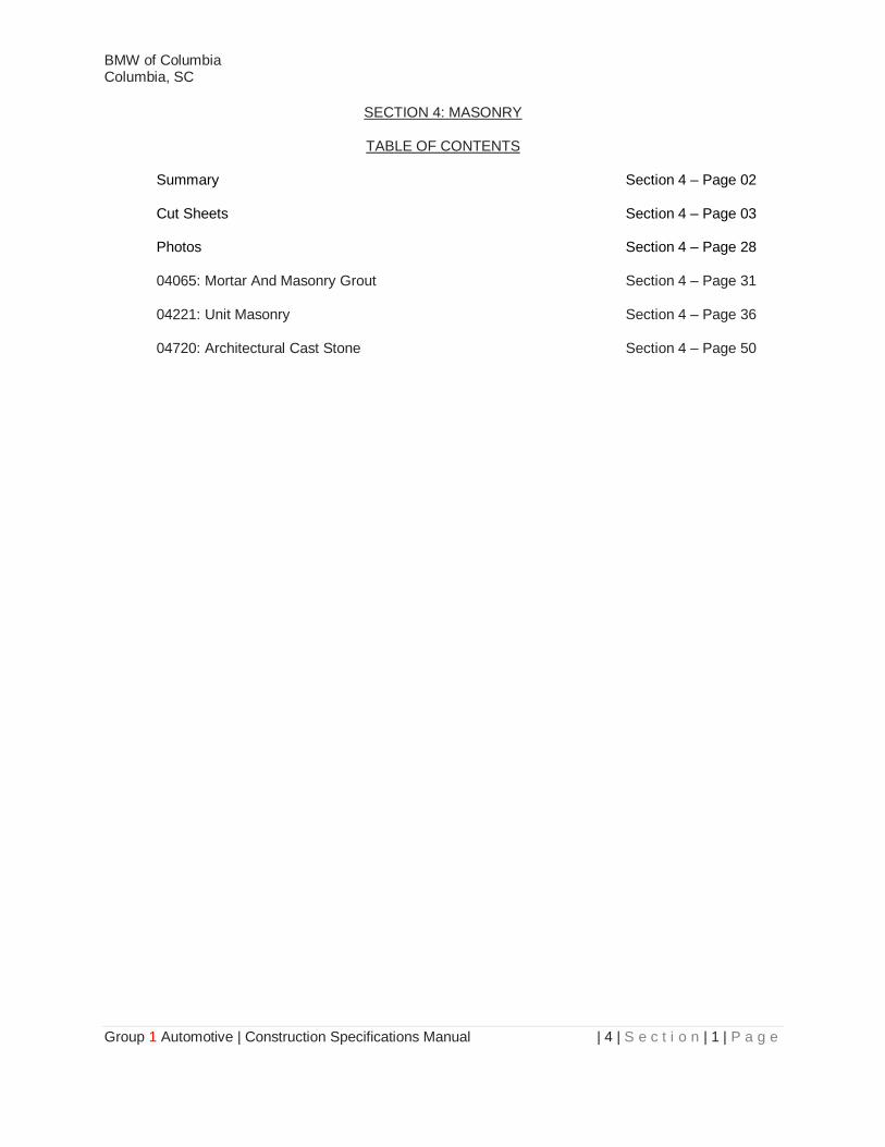
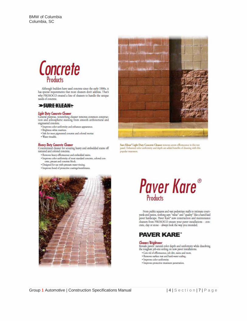
b. All completed, exposed masonry walls shall be cleaned of all dirt and efflorescence
prior to building occupancy using an appropriate Sure Klean product or approved equal.
c. All Concrete Mix Designs shall be made specifically for this project, based on the
parameters detailed on the Construction Drawings. All Designs shall be submitted to
the Design Team a minimum of four weeks prior to the pour date so that changes can
be made if required.
2. Unit Masonry
a. Concrete masonry units to be sized as indicated on drawings. All exterior masonry units
exposed to weathering and the environments are to be coated with elastomeric coating
per painting specifications, color as indicated in drawings. All exterior masonry units not
grouted are to receive foamed in place insulation, see related specifications.
3. Architectural Cast Stone
a. Cast stone wall caps to be applied to partial height walls in service shops and where
indicated on plans. Position the walls caps such that the "low" side if facing the service
and repair bays.

BMW of Columbia Columbia, SC
Group 1 Automotive | Construction Specifications Manual | 4 | S e c t i o n | 3 | P a g e
SECTION 4
MASONRY BEST PRACTICE CUT SHEETS

BMW of Columbia Columbia, SC
Group 1 Automotive | Construction Specifications Manual | 4 | S e c t i o n | 4 | P a g e

BMW of Columbia Columbia, SC
Group 1 Automotive | Construction Specifications Manual | 4 | S e c t i o n | 5 | P a g e

BMW of Columbia Columbia, SC
Group 1 Automotive | Construction Specifications Manual | 4 | S e c t i o n | 6 | P a g e
BMW of Columbia Columbia, SC
Group 1 Automotive | Construction Specifications Manual | 4 | S e c t i o n | 7 | P a g e
BMW of Columbia Columbia, SC
Group 1 Automotive | Construction Specifications Manual | 4 | S e c t i o n | 8 | P a g e
BMW of Columbia Columbia, SC
Group 1 Automotive | Construction Specifications Manual | 4 | S e c t i o n | 9 | P a g e
BMW of Columbia Columbia, SC
Group 1 Automotive | Construction Specifications Manual | 4 | S e c t i o n | 10 | P a g e
BMW of Columbia Columbia, SC
Group 1 Automotive | Construction Specifications Manual | 4 | S e c t i o n | 11 | P a g e

BMW of Columbia Columbia, SC
Group 1 Automotive | Construction Specifications Manual | 4 | S e c t i o n | 12 | P a g e
BMW of Columbia Columbia, SC
Group 1 Automotive | Construction Specifications Manual | 4 | S e c t i o n | 13 | P a g e
BMW of Columbia Columbia, SC
Group 1 Automotive | Construction Specifications Manual | 4 | S e c t i o n | 14 | P a g e
BMW of Columbia Columbia, SC
Group 1 Automotive | Construction Specifications Manual | 4 | S e c t i o n | 15 | P a g e
BMW of Columbia Columbia, SC
Group 1 Automotive | Construction Specifications Manual | 4 | S e c t i o n | 16 | P a g e
BMW of Columbia Columbia, SC
Group 1 Automotive | Construction Specifications Manual | 4 | S e c t i o n | 17 | P a g e

BMW of Columbia Columbia, SC
Group 1 Automotive | Construction Specifications Manual | 4 | S e c t i o n | 18 | P a g e

BMW of Columbia Columbia, SC
Group 1 Automotive | Construction Specifications Manual | 4 | S e c t i o n | 19 | P a g e

BMW of Columbia Columbia, SC
Group 1 Automotive | Construction Specifications Manual | 4 | S e c t i o n | 20 | P a g e
BMW of Columbia Columbia, SC
Group 1 Automotive | Construction Specifications Manual | 4 | S e c t i o n | 21 | P a g e

BMW of Columbia Columbia, SC
Group 1 Automotive | Construction Specifications Manual | 4 | S e c t i o n | 22 | P a g e

BMW of Columbia Columbia, SC
Group 1 Automotive | Construction Specifications Manual | 4 | S e c t i o n | 23 | P a g e

BMW of Columbia Columbia, SC
Group 1 Automotive | Construction Specifications Manual | 4 | S e c t i o n | 24 | P a g e
BMW of Columbia Columbia, SC
Group 1 Automotive | Construction Specifications Manual | 4 | S e c t i o n | 25 | P a g e

BMW of Columbia Columbia, SC
Group 1 Automotive | Construction Specifications Manual | 4 | S e c t i o n | 26 | P a g e

BMW of Columbia Columbia, SC
Group 1 Automotive | Construction Specifications Manual | 4 | S e c t i o n | 27 | P a g e
This Page Left Blank Intentionally
BMW of Columbia Columbia, SC
Group 1 Automotive | Construction Specifications Manual | 4 | S e c t i o n | 28 | P a g e
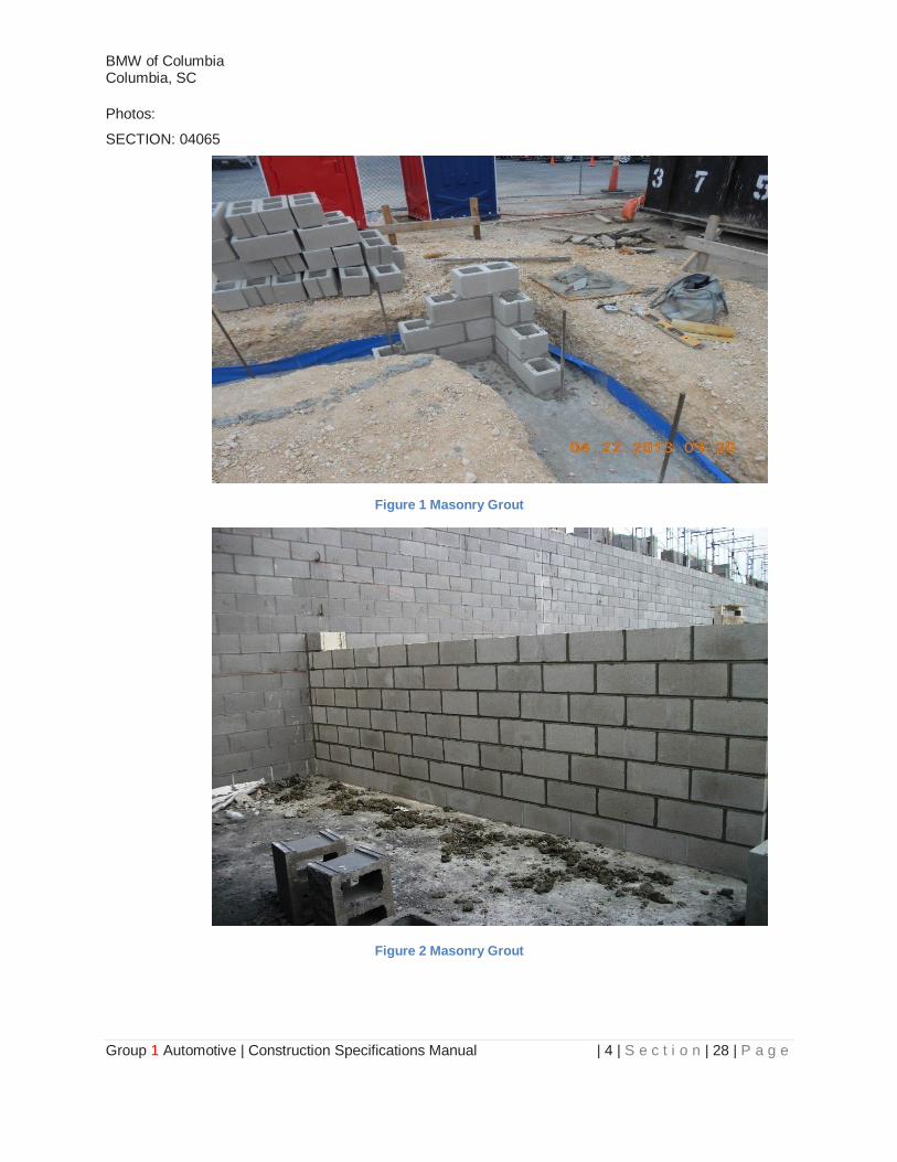
Photos:
SECTION: 04065
Figure 1 Masonry Grout
Figure 2 Masonry Grout
BMW of Columbia Columbia, SC
Group 1 Automotive | Construction Specifications Manual | 4 | S e c t i o n | 29 | P a g e
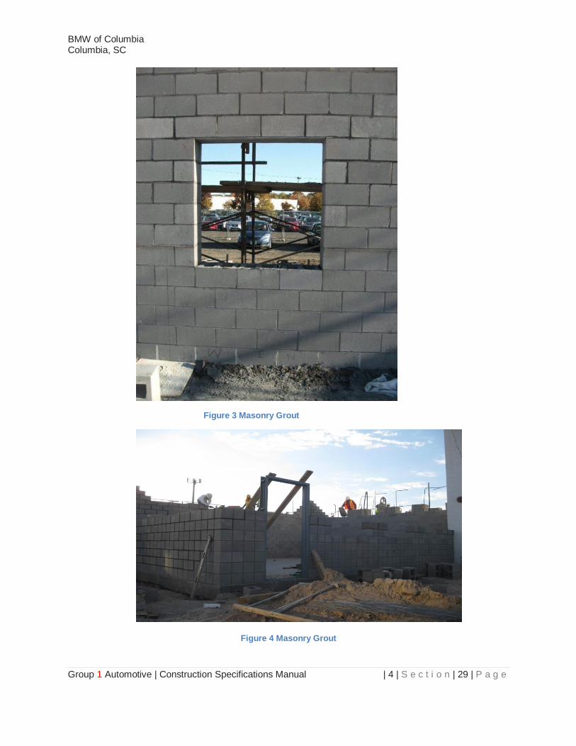
Figure 3 Masonry Grout
Figure 4 Masonry Grout

BMW of Columbia Columbia, SC
Group 1 Automotive | Construction Specifications Manual | 4 | S e c t i o n | 30 | P a g e
This Page Left Blank Intentionally
BMW of Columbia Columbia, SC
Group 1 Automotive | Construction Specifications Manual | 4 | S e c t i o n | 31 | P a g e
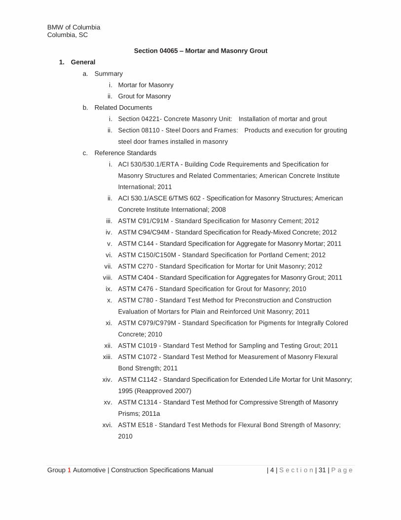
Section 04065 – Mortar and Masonry Grout
1. General
a. Summary
i. Mortar for Masonry
ii. Grout for Masonry
b. Related Documents
i. Section 04221- Concrete Masonry Unit: Installation of mortar and grout
ii. Section 08110 - Steel Doors and Frames: Products and execution for grouting
steel door frames installed in masonry
c. Reference Standards
i. ACI 530/530.1/ERTA - Building Code Requirements and Specification for
Masonry Structures and Related Commentaries; American Concrete Institute
International; 2011
ii. ACI 530.1/ASCE 6/TMS 602 - Specification for Masonry Structures; American
Concrete Institute International; 2008
iii. ASTM C91/C91M - Standard Specification for Masonry Cement; 2012
iv. ASTM C94/C94M - Standard Specification for Ready-Mixed Concrete; 2012
v. ASTM C144 - Standard Specification for Aggregate for Masonry Mortar; 2011
vi. ASTM C150/C150M - Standard Specification for Portland Cement; 2012
vii. ASTM C270 - Standard Specification for Mortar for Unit Masonry; 2012
viii. ASTM C404 - Standard Specification for Aggregates for Masonry Grout; 2011
ix. ASTM C476 - Standard Specification for Grout for Masonry; 2010
x. ASTM C780 - Standard Test Method for Preconstruction and Construction
Evaluation of Mortars for Plain and Reinforced Unit Masonry; 2011
xi. ASTM C979/C979M - Standard Specification for Pigments for Integrally Colored
Concrete; 2010
xii. ASTM C1019 - Standard Test Method for Sampling and Testing Grout; 2011
xiii. ASTM C1072 - Standard Test Method for Measurement of Masonry Flexural
Bond Strength; 2011
xiv. ASTM C1142 - Standard Specification for Extended Life Mortar for Unit Masonry;
1995 (Reapproved 2007)
xv. ASTM C1314 - Standard Test Method for Compressive Strength of Masonry
Prisms; 2011a
xvi. ASTM E518 - Standard Test Methods for Flexural Bond Strength of Masonry;
2010
BMW of Columbia Columbia, SC
Group 1 Automotive | Construction Specifications Manual | 4 | S e c t i o n | 32 | P a g e
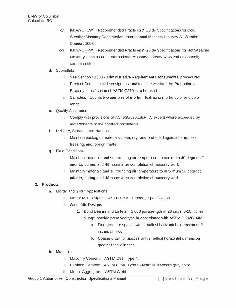
xvii. IMIAWC (CW) - Recommended Practices & Guide Specifications for Cold
Weather Masonry Construction; International Masonry Industry All-Weather
Council; 1993
xviii. IMIAWC (HW) - Recommended Practices & Guide Specifications for Hot Weather
Masonry Construction; International Masonry Industry All-Weather Council;
current edition
d. Submittals
i. See Section 01300 - Administrative Requirements, for submittal procedures
ii. Product Data: Include design mix and indicate whether the Proportion or
Property specification of ASTM C270 is to be used
iii. Samples: Submit two samples of mortar, illustrating mortar color and color
range
e. Quality Assurance
i. Comply with provisions of ACI 530/530.1/ERTA, except where exceeded by
requirements of the contract documents
f. Delivery, Storage, and Handling
i. Maintain packaged materials clean, dry, and protected against dampness,
freezing, and foreign matter
g. Field Conditions
i. Maintain materials and surrounding air temperature to minimum 40 degrees F
prior to, during, and 48 hours after completion of masonry work
ii. Maintain materials and surrounding air temperature to maximum 90 degrees F
prior to, during, and 48 hours after completion of masonry work
2. Products
a. Mortar and Grout Applications
i. Mortar Mix Designs: ASTM C270, Property Specification
ii. Grout Mix Designs
1. Bond Beams and Lintels: 3,000 psi strength at 28 days; 8-10 inches
slump; provide premixed type in accordance with ASTM C 94/C 94M
a. Fine grout for spaces with smallest horizontal dimension of 2
inches or less
b. Coarse grout for spaces with smallest horizontal dimension
greater than 2 inches
b. Materials
i. Masonry Cement: ASTM C91, Type N
ii. Portland Cement: ASTM C150, Type I - Normal; standard gray color
iii. Mortar Aggregate: ASTM C144

BMW of Columbia Columbia, SC
Group 1 Automotive | Construction Specifications Manual | 4 | S e c t i o n | 33 | P a g e
iv. Grout Aggregate: ASTM C404
v. Pigments for Colored Mortar: Pure, concentrated mineral pigments specifically
intended for mixing into mortar and complying with ASTM C979/C979M
vi. Water: Clean and potable
vii. Bonding Agent: Latex type
c. Mortar Mixes
i. Ready Mixed Mortar: ASTM C1142, Type RM
ii. Mortar for Unit Masonry: ASTM C270, Property Specification
1. Engineered masonry: Type M
2. Masonry below grade and in contact with earth: Type S
3. Exterior, loadbearing masonry: Type N
4. Exterior, non-loadbearing masonry: Type N
5. Interior, loadbearing masonry: Type N
6. Interior, non-loadbearing masonry: Type O
7. Pointing mortar: Type N with maximum 2 percent ammonium stearate
or calcium stearate per cement weight
iii. Colored Mortar: Proportion selected pigments and other ingredients to match
Architect of Record's sample, without exceeding manufacturer's recommended
pigment-to-cement ratio
d. Mortar Mixing
i. Thoroughly mix mortar ingredients using mechanical batch mixer, in accordance
with ASTM C270 and in quantities needed for immediate use
ii. Maintain sand uniformly damp immediately before the mixing process
iii. Add mortar color in accordance with manufacturer's instructions. Provide
uniformity of mix and coloration
iv. Do not use anti-freeze compounds to lower the freezing point of mortar
v. If water is lost by evaporation, re-temper only within two hours of mixing
vi. Use mortar within two hours after mixing at temperatures of 90ᴼ Fahrenheit, or
two-and-one-half hours at temperatures under 40ᴼ Fahrenheit
e. Grout Mixes
i. Bond Beams and Lintels: 3,000 psi strength at 28 days; 8-10 inches slump;
provide premixed type in accordance with ASTM C 94/C 94M
1. Fine grout for spaces with smallest horizontal dimension of 2 inches or
less.
2. Coarse grout for spaces with smallest horizontal dimension greater than
2 inches

BMW of Columbia Columbia, SC
Group 1 Automotive | Construction Specifications Manual | 4 | S e c t i o n | 34 | P a g e
ii. Engineered Masonry: 3,000 psi strength at 28 days; 8-10 inches slump; provide
premixed type in accordance with ASTM C 94/C 94M
1. Fine grout for spaces with smallest horizontal dimension of 2 inches or
less.
2. Coarse grout for spaces with smallest horizontal dimension greater than
2 inches
f. Grout Mixing
i. Mix grout in accordance with ASTM C94/C94M
ii. Thoroughly mix grout ingredients in quantities needed for immediate use in
accordance with ASTM C476 for fine and coarse grout
iii. Add admixtures in accordance with manufacturer's instructions; mix uniformly
iv. Do not use anti-freeze compounds to lower the freezing point of grout
g. Pre-Construction Testing
i. Testing will be conducted by an independent test agency, in accordance with
provisions of Section 01400.
ii. Mortar Mixes: Test mortars pre-batched by weight in accordance with ASTM
C780 recommendations for preconstruction testing.
iii. Grout Mixes: Test grout batches in accordance with ASTM C1019 procedures
3. Execution
a. Preparation
i. Apply bonding agent to existing concrete surfaces
ii. Plug clean-out holes for grouted masonry with brick masonry units. Brace
masonry to resist wet grout pressure
b. Installation
i. Install mortar and grout to requirements of section(s) in which masonry is
specified
ii. Work grout into masonry cores and cavities to eliminate voids
iii. Do not install grout in lifts greater than 16 inches without consolidating grout by
rodding
iv. Do not displace reinforcement while placing grout
v. Remove excess mortar from grout spaces
c. Grouting
i. Use either high-lift or low-lift grouting techniques, at Contractor's option, subject
to other limitations of contract documents
ii. Perform all grouting by means of low-lift technique. Do not employ high-lift
grouting
iii. Low-Lift Grouting

BMW of Columbia Columbia, SC
Group 1 Automotive | Construction Specifications Manual | 4 | S e c t i o n | 35 | P a g e
1. Limit height of pours to 12 inches
2. Limit height of masonry to 16 inches above each pour
3. Pour grout only after vertical reinforcing is in place; place horizontal
reinforcing as grout is poured. Prevent displacement of bars as grout is
poured
4. Place grout for each pour continuously and consolidate immediately;
do not interrupt pours for more than 1-1/2 hours
d. Field Quality Control
i. An independent testing agency will perform field tests, in accordance with
provisions of Section 01400
ii. Test and evaluate mortar in accordance with ASTM C780 procedures
1. Test with same frequency as specified for masonry units
iii. Test and evaluate grout in accordance with ASTM C1019 procedures
1. Test with same frequency as specified for masonry units
iv. Prism Tests: Test masonry and mortar panels for compressive strength in
accordance with ASTM C1314, and for flexural bond strength in accordance with
ASTM C1072 or ASTM E518; perform tests and evaluate results as specified in
individual masonry sections
End of Section 04065
BMW of Columbia Columbia, SC
Group 1 Automotive | Construction Specifications Manual | 4 | S e c t i o n | 36 | P a g e
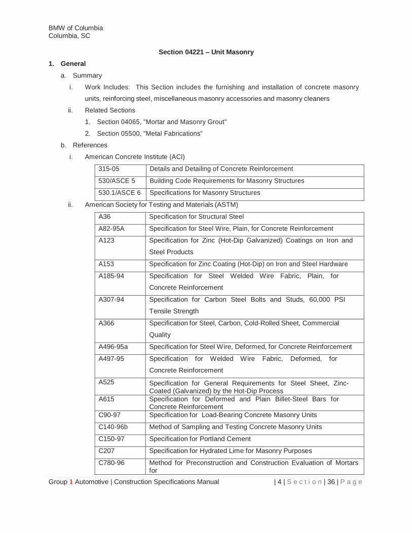
Section 04221 – Unit Masonry
1. General
a. Summary
i. Work Includes: This Section includes the furnishing and installation of concrete masonry
units, reinforcing steel, miscellaneous masonry accessories and masonry cleaners
ii. Related Sections
1. Section 04065, "Mortar and Masonry Grout"
2. Section 05500, "Metal Fabrications"
b. References
i. American Concrete Institute (ACI)
315-05 Details and Detailing of Concrete Reinforcement
530/ASCE 5 Building Code Requirements for Masonry Structures
530.1/ASCE 6 Specifications for Masonry Structures
ii. American Society for Testing and Materials (ASTM)
A36 Specification for Structural Steel
A82-95A Specification for Steel Wire, Plain, for Concrete Reinforcement
A123 Specification for Zinc (Hot-Dip Galvanized) Coatings on Iron and
Steel Products
A153 Specification for Zinc Coating (Hot-Dip) on Iron and Steel Hardware
A185-94 Specification for Steel Welded Wire Fabric, Plain, for
Concrete Reinforcement
A307-94 Specification for Carbon Steel Bolts and Studs, 60,000 PSI
Tensile Strength
A366 Specification for Steel, Carbon, Cold-Rolled Sheet, Commercial
Quality
A496-95a Specification for Steel Wire, Deformed, for Concrete Reinforcement
A497-95 Specification for Welded Wire Fabric, Deformed, for
Concrete Reinforcement
A525 Specification for General Requirements for Steel Sheet, Zinc-Coated (Galvanized) by the Hot-Dip Process
A615 Specification for Deformed and Plain Billet-Steel Bars for Concrete Reinforcement
C90-97 Specification for Load-Bearing Concrete Masonry Units
C140-96b Method of Sampling and Testing Concrete Masonry Units
C150-97 Specification for Portland Cement
C207 Specification for Hydrated Lime for Masonry Purposes
C780-96 Method for Preconstruction and Construction Evaluation of Mortars for
BMW of Columbia Columbia, SC
Group 1 Automotive | Construction Specifications Manual | 4 | S e c t i o n | 37 | P a g e
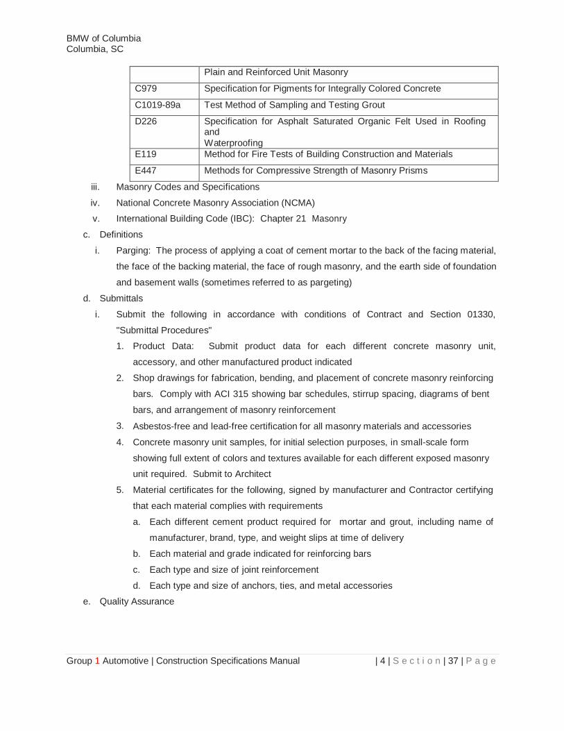
Plain and Reinforced Unit Masonry
C979 Specification for Pigments for Integrally Colored Concrete
C1019-89a Test Method of Sampling and Testing Grout
D226 Specification for Asphalt Saturated Organic Felt Used in Roofing and
Waterproofing
E119 Method for Fire Tests of Building Construction and Materials
E447 Methods for Compressive Strength of Masonry Prisms
iii. Masonry Codes and Specifications
iv. National Concrete Masonry Association (NCMA)
v. International Building Code (IBC): Chapter 21 Masonry
c. Definitions
i. Parging: The process of applying a coat of cement mortar to the back of the facing material,
the face of the backing material, the face of rough masonry, and the earth side of foundation
and basement walls (sometimes referred to as pargeting)
d. Submittals
i. Submit the following in accordance with conditions of Contract and Section 01330,
"Submittal Procedures"
1. Product Data: Submit product data for each different concrete masonry unit,
accessory, and other manufactured product indicated
2. Shop drawings for fabrication, bending, and placement of concrete masonry reinforcing
bars. Comply with ACI 315 showing bar schedules, stirrup spacing, diagrams of bent
bars, and arrangement of masonry reinforcement
3. Asbestos-free and lead-free certification for all masonry materials and accessories
4. Concrete masonry unit samples, for initial selection purposes, in small-scale form
showing full extent of colors and textures available for each different exposed masonry
unit required. Submit to Architect
5. Material certificates for the following, signed by manufacturer and Contractor certifying
that each material complies with requirements
a. Each different cement product required for mortar and grout, including name of
manufacturer, brand, type, and weight slips at time of delivery
b. Each material and grade indicated for reinforcing bars
c. Each type and size of joint reinforcement
d. Each type and size of anchors, ties, and metal accessories
e. Quality Assurance

BMW of Columbia Columbia, SC
Group 1 Automotive | Construction Specifications Manual | 4 | S e c t i o n | 38 | P a g e
i. Fire Performance Characteristics: Where indicated on the drawings, provide materials and
construction identical to those of assemblies whose fire resistance has been determined
per ASTM E119 by Underwriter s Laboratories
ii. Single-Source Responsibility for Masonry Units: Obtain concrete masonry units of uniform
texture and color, or a uniform blend within the ranges accepted for these characteristics,
from one manufacturer for each different product required for each surface or
visually related surfaces
iii. Single-Source Responsibility for Mortar Materials: Obtain mortar ingredients of uniform
quality, including color for masonry, from one manufacturer for each cementitious
component and from one source and producer for each aggregate
iv. All masonry units shall be sound, free of cracks or other defects that may interfere with the
proper placing of the unit or impair the strength of construction
v. Where units are to be used in exposed wall construction, the exposed masonry faces shall
not show chips or cracks, or imperfections when viewed from a distance of not less than 20
feet (6.1 m) under diffused lighting
vi. Use of damaged items is prohibited except by specific authorization of the Sandia
Delegated Representative (SDR)
vii. Testing: The owner shall obtain a qualified independent testing laboratory to perform the
following testing indicated for source and field quality control
1. Testing Frequency: Tests and evaluations listed in this article may be performed
during construction for each 5000 sq. ft of wall area, or as otherwise directed by the
Architect/Engineer
2. Concrete Masonry Unit Tests: For each different concrete masonry unit indicated, units
will be tested for strength, absorption, and moisture content per ASTM C140
3. Prism Test Method: For each type of wall construction indicated, masonry prisms will
be tested per ASTM E447, Method B. Prepare one set of prisms for testing at 7 days
and one set for testing at 28 days
f. Delivery, Storage, and Handling
i. Deliver masonry materials to project in undamaged condition
ii. Store and handle masonry units off the ground, under cover, and in a dry location
to prevent their deterioration or damage due to moisture, temperature changes,
contaminants, corrosion, and other causes. If units become wet, do not place until units are
in an air-dried condition
iii. Store cementitious materials off the ground, under cover, and in dry location
iv. Store aggregates where grading and other required characteristics can be maintained and
contamination avoided. Store different aggregates separately

BMW of Columbia Columbia, SC
Group 1 Automotive | Construction Specifications Manual | 4 | S e c t i o n | 39 | P a g e
v. Store masonry accessories including metal items to prevent corrosion and accumulation of
dirt and oil
vi. Protect reinforcement, ties, and metal accessories form permanent distortion and store
them off the ground
g. Project Conditions
i. Protection of Masonry: During erection, cover tops of walls, projections, and sills with
waterproof sheeting at end of each day's work. Cover partially completed masonry when
construction is not in progress. Extend cover a minimum of 24 inches down both sides and
hold cover securely in place
ii. Do not apply uniform floor or roof loads for at least 12 hours and concentrated loads for at
least 3 days after building masonry walls or columns
iii. Stain Prevention: Prevent grout, mortar, and soil from staining the face of masonry to be
left exposed or painted. Remove immediately any grout, mortar, and soil that come in
contact with such masonry
1. Protect base of walls from rain-splashed mud and mortar splatter by means of
coverings spread on ground and over wall surface
2. Protect sills, ledges, and projections from mortar droppings
3. Protect surfaces of windows and door frames, as well as similar products with painted
and integral finishes from mortar droppings
iv. Cold-Weather Construction: Comply with the following when ambient temperature falls
below 40o F
1. General: Remove masonry damaged by freezing conditions. Do not lay masonry units
having temperature below 20o F. Remove visible ice on masonry units before the
unit is laid
2. Specific requirements for various temperature ranges are as follows
a. Aggregates and mixing water shall be heated to produce mortar and grout
temperatures between 40o F and 120o F at the time of mixing
b. Maintain mortar temperature on mortar boards above freezing until used on
masonry
c. When ambient temperature is between 20o F and 25o F provide heat sources
on both sides of walls under construction and install wind breaks when wind
velocity exceeds 15 miles per hour
d. When ambient temperature is below 20o F provide enclosures and heat sources to
maintain the temperatures above 32o F within the enclosure
3. Protection

BMW of Columbia Columbia, SC
Group 1 Automotive | Construction Specifications Manual | 4 | S e c t i o n | 40 | P a g e
a. When mean daily temperature is between 40o F and 32o F protect
completed masonry from rain or snow by covering with weather-resistive membrane
for 24 hours after construction
b. When mean daily temperature is between 32o F and 25o F completely cover
completed masonry with weather-resistive membrane for 24 hours after construction
c. When mean daily temperature is between 25o F and 20o F completely cover
completed masonry with insulating blankets or equal protection for 24 hours after
construction
d. When mean daily temperature is below 20o F maintain masonry temperature above
32o F for 24 hours after construction by enclosure with supplementary heat, by
electric heating blankets, by infrared heat lamps, or by other acceptable methods
v. Hot-Weather Construction: Protect masonry construction from direct exposure to wind and
sun when erected in ambient temperature of 90ᴼ Fahrenheit or greater in the shade, with
a relative humidity less than 50%.
1. Do not spread mortar beds more than 4 feet ahead of masonry. Set masonry units
within one minute of spreading mortar. Dampen, but do not saturate masonry units
immediately before installation
2. Mortar can be re-tempered with cool water only once to maintain consistency
3. Protection: When the mean daily temperature exceeds 100o F or exceeds 90o F with
a wind velocity greater than 8 mph, fog spray all newly constructed masonry until damp,
at least three times a day until the masonry is three days old
2. Products
a. Concrete Masonry Units
i. Load-Bearing Concrete Masonry Units: ASTM C90, and as follows
1. Unit Compressive Strength: Provide units with minimum average net area compressive
strength of 1900 psi
2. Size: Provide manufacturer s standard units with nominal face dimensions of 8" wide x
8" high x 16" long actual dimensions 7-5/8" x 7-5/8" x 15-5/8" unless otherwise
indicated
3. Provide Type I, moisture-controlled units
4. Weight Classification: Normal weight
ii. Provide special shapes where indicated and as follows
1. For lintels, corners, jambs, sash, control joints, headers, bonding, and other special
conditions
2. Bullnose units for outside corners where indicated
3. Square-edge units for outside corners, except where indicated as bullnose
BMW of Columbia Columbia, SC
Group 1 Automotive | Construction Specifications Manual | 4 | S e c t i o n | 41 | P a g e
iii. Exposed Faces: Where special finishes are indicated, provide units with the following
1. Standard aggregate, split face or split face-fluted finish
2. Standard aggregate, slump finish
3. Scoria aggregate, smooth face, split face or split face-fluted finish
b. Reinforcement
i. Steel Reinforcing Bars: ASTM A615, Grade 60
ii. Deformed Reinforcing Wire: ASTM A496
iii. Plain Welded Wire Fabric: ASTM A185
iv. Deformed Welded Wire Fabric: ASTM A497
v. Joint Reinforcement: 9 gage deformed side rods and diagonal rods, in accordance with
ASTM A951
1. Galvanized in accordance with ASTM A641 for internal applications and ASTM A153
for external applications
2. Description: Prefabricated ladder type welded-wire units with deformed continuous
side rods and diagonal rods, spaced no more than 16" O.C. into straight lengths of not
less than 10 feet with prefabricated corner and tee units
3. Available Manufacturers: Subject to compliance with requirements, manufacturers
offering joint reinforcement that may be incorporated in the work include, but are not
limited to, the following
a. AA Wire Products Co.
b. Duro-O-Wal, Inc.
c. Heckman Building Products, Inc.
d. Hohmann & Barnard, Inc.
c. Ties and Anchors
i. Galvanized Carbon Steel Wire: ASTM A82, hot-dip galvanized after fabrication to comply
with ASTM A153, Class B2. Wire diameter 0.1875 inch unless otherwise indicated
ii. Galvanized Steel Sheet: ASTM A366 (commercial quality) cold-rolled carbon steel sheet
hot-dip galvanized after fabrication to comply with ASTM A525, for sheet metal ties and
anchors. Minimum thickness 0.0598 inch (16 gage) unless otherwise indicated
iii. Steel Plates and Bars: ASTM A36, hot-dip galvanized to comply with ASTM A123 or ASTM
A153, Class B3, as applicable to size and form indicated
iv. Bent Wire Ties: Individual units prefabricated from bent wire to comply with requirements
indicated below
1. Tie Shape for Hollow Masonry Units Laid with Cells Vertical: Rectangular with closed
ends and not less than 4 inches wide
2. Tie Shape for Solid Masonry Unit Construction: Z-shaped ties with ends bent 90
degrees to provide hooks not less than 2 inches long
BMW of Columbia Columbia, SC
Group 1 Automotive | Construction Specifications Manual | 4 | S e c t i o n | 42 | P a g e
v. Adjustable Anchors for Connecting Masonry to Structural Framework: Provide two-piece
assemblies as described below allowing v ertical or horizontal differential movement
between wall and framework parallel to plane of wall, but resisting tension and compression
forces perpendicular to it.
1. For anchorage to concrete framework, provide manufacturer's standard with dovetail
anchor section formed from sheet metal and triangular-shaped wire tie section sized to
extend within 1 inch of masonry face. Wire diameter 0.1875 inch
2. For anchorage to steel framework provide manufacturer's standard anchors with
crimped 1/4-inch diameter wire anchor section for welding to steel and triangular-
shaped wire tie section sized to extend within 1 inch) of masonry face. Wire diameter
0.1875 inch
vi. Rigid Anchors: Provide straps of form and length indicated, fabricated from metal strips of
following width and thickness
1. 1-1/2 inches wide by 1/4 inch thick, unless otherwise indicated
vii. Miscellaneous Anchors
1. Unit Type Masonry Inserts in Concrete: Cast iron or malleable iron inserts of type and
size indicated
2. Dovetail Slots: Furnish dovetail slots, with filler strips, of slot size indicated, fabricated
from 0.0336-inch (22-gage) sheet metal
3. Anchor Bolts: Steel bolts complying with A307, Grade A; with ASTM A563 hex nuts
and, where indicated, flat washers; hot-dip galvanized to comply with ASTM A153,
Class C; of diameter, length and type indicated on the drawings
viii. Available Manufacturers: Subject to compliance with requirements, manufacturers offering
products that may be incorporated in the work include, but are not limited to, the following
1. AA Wire Products Co.
2. Duro-O-Wal, Inc.
3. Heckman Building Products, Inc.
4. Hohmann & Barnard, Inc.
5. Masonry Reinforcing Corp. of America
6. Southern Construction Products, Inc.
d. Miscellaneous Masonry Accessories
i. Non-metallic Expansion Joint Strips: Pre-molded neoprene filler strips complying
with ASTM D1056, Type2 (closed cell), Class A (cellular rubber and rubber-like materials
with specific resistance to petroleum base oils), Grade 1 (compression-deflection range of 2-
5 psi), compressible up to 35 percent, of width and thickness indicated
BMW of Columbia Columbia, SC
Group 1 Automotive | Construction Specifications Manual | 4 | S e c t i o n | 43 | P a g e
ii. Preformed Control Joint Gaskets: styrene-butadiene rubber compound ASTM D2000,
Designation 2AA-805., designed to fit standard sash block and to maintain lateral stability
in masonry wall; size and configuration as indicated
iii. Bond Breaker Strips: Asphalt-saturated organic roofing felt complying with ASTM D226,
Type 1(No. 15 asphalt felt).
e. Masonry Cleaners
i. Job-Mixed Detergent Solution: Solution of trisodium phosphate (1/2-cup or 118 mL dry
measure) and laundry detergent (1/2-cup or 118 mL dry measure) dissolved in one gallon
(3.78 L) of water
ii. Job-Mixed Muriatic Solution: Solution of 1 part muriatic acid and 10 parts clean water,
mixed in a nonmetallic container with acid added to water
iii. Proprietary Acidic Cleaner: Manufacturer's standard-strength, general-purpose cleaner
designed for removing mortar/grout stains, efflorescence, and other new construction
stains from new masonry surfaces of type indicated below without discoloring or damaging
masonry surfaces; expressly approved for intended use by manufacturer of masonry units
being cleaned
1. For masonry not subject to metallic oxidation stains, use formulation consisting of a
concentrated blend of surface-acting acids, chelating, and wetting agents
2. For dark colored masonry not subject to metallic oxidation stains, use formulation
consisting of a liquid blend of surface-acting acids and special inhibitors
3. For masonry subject to metallic oxidation stains, use formulation consisting of a liquid
blend of organic and inorganic acids and special inhibitors
4. Available Products: Subject to compliance with requirements, a product that may be
used to clean unit masonry surfaces includes, but is not limited to, the following
a. "Sure Klean No. 600 Detergent," ProSoCo, Inc
b. "Sure Klean No. 101 Lime Solvent," ProSoCo, Inc
c. "Sure Klean Vana Trol," ProSoCo, Inc.
f. Mortar and Grout Fills
i. Colored Cement Product: Packaged blend made from masonry cement and mortar
pigments, all complying with specified requirements, and containing no other ingredients
1. Avendra, LLC Preferred Manufacturers
a. None
2. Approved Manufacturers
a. Lehigh Cement Co.
b. Cemex
c. Custom Building Products
d. LaFarge Corporation
BMW of Columbia Columbia, SC
Group 1 Automotive | Construction Specifications Manual | 4 | S e c t i o n | 44 | P a g e
e. Essroc, Italcementi Group
3. Formulate blend as required to produce color indicated, if not indicated, as
selected from manufacturer s standard colors. Consult the architect. Use cement
with synthetic iron oxide pigment only
4. Aggregate for Mortar: ASTM C144; except for joints less than Y." thick use aggregate
graded with 100 percent passing the No. 16 sieve
a. White-Mortar Aggregates: Natural white sand or ground white stone
b. Colored Mortar Aggregates: Natural-colored sand or ground marble, granite, or
other sound stone; of color necessary to produce required mortar color
ii. Aggregate for Grout: ASTM C404
iii. Grout for Unit Masonry: Comply with ASTM C476 for grout for use in construction of
reinforced and non-reinforced unit masonry. Use grout consistency indicated or, if not
otherwise indicated, of consistency (fine or coarse) at time of placement which will
completely fill all spaces intended to receive grout. Minimum compressive strength shall be
2500 psi in 28 days
1. Use fine grout in grout spaces less than 2" in horizontal direction, unless otherwise
indicated
2. Use coarse grout (maximum 3/8" aggregate) in grout spaces 2" or more in least
horizontal dimension, unless otherwise indicated
3. Execution
a. Examination
i. Examine conditions for compliance with requirements for installation tolerances and other
specific conditions, and other conditions affecting performance of concrete masonry unit
ii. Examine rough-in and built-in construction to verify actual locations of piping connections
prior to installation
iii. Do not proceed until unsatisfactory conditions have been corrected
b. Preparation
i. Clean all reinforcement by removing mud, oil, or other materials that will adversely affect
or reduce bond at the time mortar or grout is placed. Reinforcement with rust and/or mill
scale will be accepted, provided the dimensions and weights, including heights of
deformations, are not less than required by the ASTM specification covering this
reinforcement in this Specification
ii. Prior to placing masonry, remove laitance, loose aggregate, and anything else that would
prevent mortar from bonding to the foundation
iii. Do not wet concrete masonry prior to installation, unless otherwise indicated
c. Installation
i. General

BMW of Columbia Columbia, SC
Group 1 Automotive | Construction Specifications Manual | 4 | S e c t i o n | 45 | P a g e
1. Thickness: Build masonry construction to the full thickness shown, using units of
nominal thickness indicated
2. Leave openings for equipment to be installed before completion of masonry. After
installation of equipment, complete masonry to match construction immediately
adjacent to the opening
3. Cut masonry units with motor-driven saws to provide clean, sharp, un-chipped edges.
Cut units as required to provide continuous pattern and to fit adjoining construction.
Use full-size units without cutting where possible
4. Matching Existing Masonry: Match coursing, bonding, color, and texture of new
masonry with existing masonry
ii. Masonry erection
1. Lay out walls in advance for accurate spacing of surface bond patterns with uniform
joint widths and for accurately locating openings, movement-type joints, returns, and
offsets. Avoid the use of less-than-half-size units at corners, jambs, and where
possible at other locations
2. Erect walls to comply with specified construction tolerances, with courses accurately
spaced and coordinated with other construction
3. Lay all exposed masonry in one-half running bond with vertical joint in each course
centered on units in courses above and below, do not use units with less than nominal
4-inch horizontal face dimensions at corners or jambs
4. Lay all concealed masonry with all units in running bond or bonded by lapping not less
than 2 inches. Bond and interlock each course at corners. Do not use units with less
than nominal 4-inch horizontal face dimensions at corners or jambs
5. Stopping and Resuming Work: In each course, rack back 1/2-unit length; do not tooth.
Clean exposed surfaces of set masonry, and remove loose masonry units and mortar
prior to laying fresh masonry
6. Built-In Work: As construction progresses, build in items specified under this and other
sections of the Specifications. Fill in solidly with masonry around built-in items
a. Fill space between hollow metal frames and masonry solidly with mortar, unless
otherwise indicated
b. Where built-in items are to be embedded in cores of hollow masonry units, place a
layer of metal lath in the joint below and rod mortar or grout into core
c. Fill cores in hollow concrete masonry units with grout 3 courses under bearing
plates, beams, lintels, posts, and similar items, or as otherwise indicated on the
contract drawings
BMW of Columbia Columbia, SC
Group 1 Automotive | Construction Specifications Manual | 4 | S e c t i o n | 46 | P a g e
d. Placing Mortar and units
i. Hollow concrete units
1. Face shells of bed joints fully mortared
2. Webs are fully mortared in all courses of piers, columns, and pilasters, in the starting
course on foundations, when necessary to confine grout or loose-fill insulation, and
when otherwise required.
3. For starting course on footings where cells are not grouted, spread out full mortar bed
including areas under cells
ii. Cut joints flush for masonry walls to be concealed or to be covered by other materials,
unless otherwise indicated
e. Reinforcement Installation
i. Place reinforcement in accordance with the sizes, types, and locations indicated on the
contract drawings. Horizontal reinforcement may be placed as the masonry work
progresses
ii. Reinforcement shall be secured against displacement prior to grouting by wire positioners
or other suitable devices such as wire tying, at intervals not exceeding 200 bar diameters
iii. Tolerances: Placement of reinforcement in walls and flexural elements shall be
1. + 1/2 inch when the distance from the centerline of steel to the opposite face of
masonry, d, is equal to 8 inches or less
2. + 1 inch for distance equal to 24 inches or less but greater than 8 inches
3. + 1-1/4 inch for distance greater than 24 inches
4. + 2 inches for longitudinal location of reinforcement
iv. Clearance between reinforcing steel and the surface of the masonry shall be not less 1/4
inch (6.4 mm) for fine grout and 1/2 inch for coarse grout
v. Do not bend reinforcement after it is embedded in grout or mortar
vi. Horizontal Joint Reinforcement: Provide continuous horizontal joint reinforcement as
indicated. Install longitudinal side rods in mortar for their entire length with a minimum
cover of 5/8 inch on exterior side of walls, 1/2 inch elsewhere. Lap reinforcing a minimum
of 6 inches
1. Cut or interrupt joint reinforcement at control and expansion joints, unless otherwise
indicated for structural considerations
2. Provide continuity at corners and wall intersections by use of prefabricated "L" and "T"
sections. Cut and bend reinforcement units as directed by manufacturer for continuity
at returns, offsets, column fireproofing, pipe enclosures, and other special condition
seen
BMW of Columbia Columbia, SC
Group 1 Automotive | Construction Specifications Manual | 4 | S e c t i o n | 47 | P a g e
f. Movement
i. Install control and expansion joints in masonry units where indicated. Build in related items
as the masonry progresses. Do not form a continuous span through movement joints
unless provisions are made to prevent in-plane restraint of wall or partition movement
ii. If location of control joints is not indicated on the contract drawings, place vertical joints
spaced not more than 30 feet o.c. Locate control joints at points of natural weakness in
masonry work
iii. Form control joints in concrete masonry as follows
1. Fit bond breaker strips into hollow contour in ends of block units on one side of control
joint. Fill the resultant core with grout and rake joints in exposed faces
2. Install preformed control joint gaskets designed to fit standard sash block
3. Install special shapes designed for control joints. Install bond breaker strips at joint.
Keep head joints free and clear of mortar or rake joint
iv. Build in horizontal pressure-relieving joints where indicated; construct joints by either
leaving an air space or inserting nonmetallic 50 percent compressible joint filler of width
required to permit installation of sealant and backer rod specified by the Architect
v. Locate horizontal pressure-relieving joints beneath shelf angles supporting masonry veneer
and attached to structure behind masonry veneer
g. Lintels
i. Install steel lintels where indicated
ii. Provide masonry lintels where shown and wherever openings of more than 2'-0" for block
size units are shown without structural steel or other supporting lintels. Provide precast or
formed-in-place masonry lintels. Cure precast lintels before handling and installation.
Temporarily support formed-in-place lintels
iii. For hollow concrete masonry unit walls, use specially formed bond beam units with
reinforcement bars placed as indicated and filled with coarse grout
iv. Provide minimum bearing of 8 inches (203 mm) at each jamb, unless otherwise indicated
h. Installation and Grouting of Reinforced Masonry Unit
i. Temporary Formwork: Construct formwork and shores to support reinforced masonry
elements during construction
ii. Construct formwork to conform to shape, line, and dimensions shown. Make sufficiently
tight to prevent leakage of mortar and grout. Brace, tie, and support forms to maintain
position and shape during construction and curing of reinforced masonry
iii. Do not place grout until entire height of masonry to be grouted has attained sufficient
strength to resist displacement of masonry units and breaking of mortar bond
iv. All cells and spaces containing reinforcement shall be filled with grout
BMW of Columbia Columbia, SC
Group 1 Automotive | Construction Specifications Manual | 4 | S e c t i o n | 48 | P a g e
v. Prior to grouting, grout space shall be cleaned so that all spaces to be filled with grout do
not contain mortar drippings, debris, loose aggregates, and any material deleterious to
masonry grout
vi. Place reinforcement and ties in grout spaces prior to grouting. Bolts shall be accurately set
and held in place to prevent dislocation during grouting
vii. Grouting of any section of wall shall be completed in one day with no interruption greater
than one hour
viii. Cleanouts: Provide cleanouts in the bottom course of masonry for each grout pour, when
the grout pour height exceeds 5 feet
1. Provide cleanouts adjacent to each vertical bar
2. In solid grouted masonry, space cleanouts horizontally a maximum of 32 inches o.c
3. Construct cleanouts with an opening of sufficient size to permit removal of debris.
Minimum opening dimension shall be 3 inches
4. Cleanouts shall be sealed after inspection and before grouting
ix. Place grout within 1 1/2 hour from introducing water in the mixture and prior to initial set.
x. Grout Lift Height: Place grout in lifts not exceeding 5 feet
xi. Consolidation: Consolidate grout at the time of placement
1. Consolidate grout pours 12 inches (305 mm) or less in height by mechanical vibration
or by puddling
2. Consolidate pours exceeding 12 inches (305 mm) in height by mechanical vibration
and reconsolidate by mechanical vibration after initial water loss and settlement has
occurred
i. Parging
i. Parge predampened masonry walls where indicated with Type S or M mortar applied in two
uniform coats to a total thickness of 3/4 inch. Scarify first parging coat to ensure full bond to
subsequent coat
ii. Use a steel-trowel finish to produce a smooth, flat, dense surface with a maximum surface
variation of 1/8 inch per foot. Form a wash at top of parging and a cove at bottom
iii. Damp cure parging for at least 24 hours and protect until cured
j. Repairing, Pointing and Cleaning
i. Remove and replace masonry units that are loose, chipped, broken, stained, or otherwise
damaged or if units do not match adjoining units. Install new units to match adjoining units
and in fresh mortar or grout, pointed to eliminate evidence of replacement
ii. Pointing: During the tooling of joints, enlarge any voids or holes, except weep holes, and
completely fill with mortar. Point-up all joints including corners, openings, and adjacent
construction to provide a neat, uniform appearance, prepared for application of sealants

BMW of Columbia Columbia, SC
Group 1 Automotive | Construction Specifications Manual | 4 | S e c t i o n | 49 | P a g e
iii. Final Cleaning: After mortar is thoroughly set and cured, clean exposed masonry as
follows
1. Remove large mortar particles by hand with wooden paddles and nonmetallic scrape
hoes or chisels
2. Protect adjacent stone and non-masonry surfaces from contact with cleaner by covering
them with liquid strippable masking agent, polyethylene film, or waterproof masking
tape
3. Wet wall surfaces with water prior to application of cleaners; remove cleaners promptly
by rinsing thoroughly with clear water
4. Leave the work area and surrounding surfaces clean and free of mortar, spots,
droppings and broken masonry. Remove defective or broken work and install new
work
iv. Waterproofing: After completion of final cleaning, apply waterproofing according to the
manufacturer s installation instructions ensuring that all exposed masonry surfaces receive
full coverage
End of Section 04221
BMW of Columbia Columbia, SC
Group 1 Automotive | Construction Specifications Manual | 4 | S e c t i o n | 50 | P a g e
Section 04720 – Architectural Cast Stone
1. General
a. Summary
i. Scope - All labor, materials and equipment to provide the Cast Stone shown on
architectural drawings and as described in this specification
1. Manufacturer shall furnish Cast Stone covered by this specification
2. Installing contractor shall unload, store, furnish all anchors, set, patch, clean and seal
(optional) the Cast Stone as required.
b. Related Sections
i. Section - 01330 - Submittal Procedures
ii. Section - 04065 - Mortar and masonry Grout
iii. Section - 04221 - Concrete Masonry Unit
iv. Section - 07 90 00 - Joint Protection
c. References
i. AC 318 - Building Code Requirements for Reinforced Concrete
ii. ASTM A 185 - Standard Specification for Steel Welded Wire Reinforcement, Plain, for
Concrete
iii. ASTM A 615/A 615M - Standard Specification for Deformed and Plain Billet-Steel Bars
for Reinforced Concrete
iv. ASTM C 33 - Standard Specification for Concrete Aggregates
v. ASTM C 150 - Standard Specification for Portland Cement
vi. ASTM C 173 - Standard Test Method for Air Content of Freshly Mixed Concrete by the
Volume Method
vii. ASTM C 231 - Standard Test Method for Air Content of Freshly Mixed Concrete by the
Pressure Method
viii. ASTM C 260 - Standard Specification for Air-Entrained Admixtures for Concrete
ix. ASTM C 270 - Standard Specification for Mortar for Unit Masonry
x. ASTM C 426 - Standard Test Method for Linear Shrinkage of Concrete Masonry Units
xi. ASTM C 494/C 494M - Standard Specification for Chemical Admixtures for Concrete
xii. ASTM C 618 - Specification for Coal Fly Ash and Raw or Calcined Natural Pozzolan for
Use as a Mineral Admixture in Concrete
xiii. ASTM C 666 - Standard Test Method for Resistance of Concrete to Rapid Freezing and
Thawing
xiv. ASTM C 979 - Standard Specification for Coloring Pigments for integrally Pigmented
Concrete
xv. ASTM C 989 - Standard Specification for Ground Granulated Blast-Furnace Slag for Use
in Concrete
BMW of Columbia Columbia, SC
Group 1 Automotive | Construction Specifications Manual | 4 | S e c t i o n | 51 | P a g e
xvi. ASTM C 1194 - Standard Test Method for Compressive Strength of Architectural Cast
Stone
xvii. ASTM C 1195 - Standard Test Method for Absorption of Architectural Cast Stone
xviii. ASTM C 1364 - Standard Specification for Architectural Cast Stone
xix. ASTM D 2244 - Standard Test Method for Calculation of Color Differences from
instrumentally Measured Color Coordinates
xx. Cast Stone institute® Technical Manual (Current Edition)
d. Definitions
i. A. Cast Stone - a refined architectural concrete building unit manufactured to simulate
natural cut stone, used in unit masonry applications
1. Dry Cast Concrete Products - manufactured from zero slump concrete.
a. Vibrant Dry Tamp (VDT) casting method: Vibratory ramming of earth moist, zero-
slump concrete against a rigid mold until it is densely compacted.
b. Machine casting method: manufactured from earth moist, zero-slump concrete
compacted by machinery using vibration and pressure against a mold until it
becomes densely consolidated
ii. Wet Cast Concrete Products - manufactured from measurable slump concrete
1. Wet casting method: manufactured from measurable slump concrete and vibrated into
a mold until it becomes densely consolidated
e. Submittal Procedures
i. Comply with Section 01330 - Submittal Procedures
ii. Samples: Submit pieces of the Cast Stone that are representative of the general range of
finish and color proposed to be furnished for the project
iii. Test results: Submit manufacturers test results of Cast Stone previously made by the
manufacturer
iv. Shop Drawings: Submit manufacturers shop drawings including profiles, cross-sections,
reinforcement, exposed faces, arrangement of joints (optional for standard or semi-
custom installations), anchoring methods, anchors (if required), annotation of stone types
and their location
f. Quality Assurance
i. Manufacturer Qualifications
1. Manufacturer shall have sufficient plant facilities to produce the shapes, quantities and
size of Cast Stone required in accordance with the project schedule.
2. Manufacturer shall submit a written list of projects similar in scope and at least three
(3) years of age, along with owner, architect and contractor references

BMW of Columbia Columbia, SC
Group 1 Automotive | Construction Specifications Manual | 4 | S e c t i o n | 52 | P a g e
ii. Standards: Comply with the requirements of the Cast Stone institute® Technical Manual
and the project specifications. Where a conflict may occur, the contract documents shall
prevail.
iii. Mock-up (Optional) Provide full size unit(s) for use in construction of sample wall. The
approved mock-up shall become the standard for appearance and workmanship for the
project
g. Acceptable Manufacturer
i. A. Melton Classics Incorporated
P.O. Box 465020
Lawrenceville, GA 30042-5020 770-963-3060 800-963-3060 Fax 770-9626988 [email protected] www.MeltonClassics.com
2. Products
a. Architectural Cast Stone
i. Comply with ASTM C 1364
1. Physical properties: Provide the following
a. Compressive Strength - ASTM C 1194: 6,500 psi (45 Mpa) minimum for products
at 28 days
b. Absorption - ASTM C 1195: 6% maximum by the cold water method, or 10%
maximum by the boiling method for products at 28 days
c. Air Content - ASTM C173 or C 231, for wet cast product shall be 4-8% for units
exposed to freeze-thaw environments. Air entrainment is not required for VDT
products
d. Freeze-thaw - ASTM C 1364: The CPWL shall be less than 5% after 300 cycles
of freezing and thawing
e. Linear Shrinkage - ASTM C 426: Shrinkage shall not exceed 0.065%
2. Job site testing - One (1) sample from production units may be selected at random
from the field for each 500 cubic feet (14 m 3) delivered to the job site
a. Three (3) field cut cube specimens from each of these samples shall have an
average minimum compressive strength of not less than 85% with no single
specimen testing less than 75% of design strength as allowed by AC 318
b. Three (3) field cut cube specimens from each of these samples shall have an
average maximum cold-water absorption of 6%
c. Field specimens shall be tested in accordance with ASTM C 1194 and C 1195
BMW of Columbia Columbia, SC
Group 1 Automotive | Construction Specifications Manual | 4 | S e c t i o n | 53 | P a g e
b. Raw Materials
i. Portland cement - Type or Type , white and/or grey, ASTM C 150
ii. Coarse aggregates - Granite, quartz or limestone, ASTM C 33, except for gradation, and
are optional for the VDT casting method
iii. Fine aggregates - Manufactured or natural sands, ASTM C 33, except for gradation
iv. Colors - organic iron oxide pigments, ASTM C 979 except that carbon black pigments
shall not be used
v. Admixtures- Comply with the following
1. ASTM C 260 for air-entraining admixtures
2. ASTM C 494/C 495M Types A - G for water reducing, retarding, accelerating and high
range admixtures
3. Other admixtures: integral water repellents and other chemicals, for which no ASTM
Standard exists, shall be previously established as suitable for use in concrete by
proven field performance or through laboratory testing
4. ASTM C 618 mineral admixtures of dark and variable colors shall not be used in
surfaces intended to be exposed to view
5. ASTM C 989 granulated blast furnace slag may be used to improve physical
properties. Tests are required to verify these features
vi. Water – Potable
vii. Reinforcing Bars
1. ASTM A 615/A 615M. Grade 40 or 60 steel galvanized or epoxy coated when cover is
less than 1.5 in. (37 mm)
2. Welded Wire Fabric: ASTM A 185 where applicable for wet cast units
viii. All anchors, dowels and other anchoring devices and shims shall be standard building
stone anchors commercially available in a non-corrosive material such as zinc plated,
galvanized steel, brass, or stainless steel Type 302 or 304
c. Color And Finish
i. Match sample on file in architect s office
ii. All surfaces intended to be exposed to view shall have a fine-grained texture similar to
natural stone, with no air voids in excess of 1/32 in. (0.8 mm) and the density of such
voids shall be less than 3 occurrences per any 1 in.2 (25 mm2) and not obvious under
direct daylight illumination at a 5 ft (1.5m) distance
iii. Units shall exhibit a texture approximately equal to the approved sample when viewed
under direct daylight illumination at a 10 ft (3 m) distance
1. ASTM D 2244 permissible variation in color between units of comparable age
subjected to similar weathering exposure
a. Total color difference - not greater than 6 units

BMW of Columbia Columbia, SC
Group 1 Automotive | Construction Specifications Manual | 4 | S e c t i o n | 54 | P a g e
b. Total hue difference - not greater than 2 units
iv. Minor chipping resulting from shipment and delivery shall not be grounds for rejection.
Minor chips shall not be obvious under direct daylight illumination from a 20-ft (6 m)
distance
v. The occurrence of crazing or efflorescence shall not constitute a cause for rejection
vi. Remove cement film, if required, from exposed surfaces prior to packaging for shipment
d. Reinforcing
i. Reinforce the units as required by the drawings and for safe handling and structural
stress
ii. Minimum reinforcing shall be 0.25 percent of the cross section area
iii. Reinforcement shall be noncorrosive where faces exposed to weather are covered with
less than 1.5 in. (38 mm) of concrete material. All reinforcement shall have minimum
coverage of twice the diameter of the bars
iv. Panels, soffits and similar stones greater than 24 in. (600 mm) in one direction shall be
reinforced in that direction. Units less than 24 in. (600 mm) in both their length and width
dimension shall be non-reinforced unless otherwise specified
v. Welded wire fabric reinforcing shall not be used in dry cast products
e. Curing
i. Cure units in a warm curing chamber approximately 100°F (37.8°F) at 95 percent relative
humidity for approximately 12 hours, or cure in a 95 percent moist environment at a
minimum 70°F (21.1°F) for 16 hours after casting. Additional yard curing at 95 percent
relative humidity shall be 350 degree-days (i.e. 7 days @ 50°F (10°F) or 5 days @ 70°F
(21°F)) prior to shipping. Form cured units shall be protected from moisture evaporation
with curing blankets or curing compounds after casting
f. Manufacturing Tolerances
i. Cross section dimensions shall not deviate by more than 1/8 in. (3 mm) from approved
dimensions
ii. Length of units shall not deviate by more than length/ 360 or 1/8 in. (3 mm), whichever is
greater, not to exceed 1/4 in. (6 mm)
1. Maximum length of any unit shall not exceed 15 times the average thickness of such
unit unless otherwise agreed by the manufacturer
iii. Warp, bow or twist of units shall not exceed length/ 360 or 1/8 in. (3 mm), whichever is
greater
iv. Location of dowel holes, anchor slots, flashing grooves, false joints and similar features
- On formed sides of unit, 1/8 in. (3 mm), on unformed sides of unit, 3/8 in. (9 mm)
maximum deviation

BMW of Columbia Columbia, SC
Group 1 Automotive | Construction Specifications Manual | 4 | S e c t i o n | 55 | P a g e
g. Production Quality Control
i. Testing
1. Test compressive strength and absorption from specimens selected at random from
plant production
2. Samples shall be taken and tested from every 500 (14 m3) cubic feet of product
produced
3. Perform tests in accordance ASTM C 1194 and C 1195
4. New and existing mix designs shall be tested for strength and absorption compliance
prior to producing units
h. Delivery, Storage And Handling
i. Mark production units with the identification marks as shown on the shop drawings
ii. Package units and protect them from staining or damage during shipping and storage
iii. Provide an itemized list of product to support the bill of lading
3. Execution
a. Examination
i. Installing contractor shall check Cast Stone materials for fit and finish prior to installation.
Do not set unacceptable units
b. Setting Tolerances
i. Comply with Cast Stone institute® Technical Manual
ii. Set stones 1/8 in. (3 mm) or less, within the plane of adjacent units
iii. Joints, plus - 1/16 in. (1.5 mm), minus - 1/8 in. (3 mm)
c. Jointing
i. Joint size
1. At stone/brick joints 3/8 in. (9.5 cm)
2. At stone/stone joints in vertical position 1/4 in. (6 mm) (3/8 in. (9.5 mm) optional)
3. Stone/stone joints exposed on top 3/8 in. (9.5 mm)
ii. Joint materials
1. Mortar, Type N, ASTM C 270
2. Use a full bed of mortar at all bed joints
3. Flush vertical joints full with mortar
4. Leave all joints with exposed tops or under relieving angles open for sealant
5. Leave head joints in copings and projecting components open for sealant
iii. Location of joints
1. As shown on shop drawings
2. At control and expansion joints unless otherwise shown
BMW of Columbia Columbia, SC
Group 1 Automotive | Construction Specifications Manual | 4 | S e c t i o n | 56 | P a g e
d. Setting
i. Drench units with clean water prior to setting
ii. Fill dowel holes and anchor slots completely with mortar or non-shrink grout
iii. Set units in full bed of mortar, unless otherwise detailed
iv. Rake mortar joints 3/4 in. (18 mm) in. for pointing
v. Remove excess mortar from unit faces immediately after setting
vi. Tuck point unit joints to a slight concave profile
e. Joint Protection
i. Comply with requirements of Section 07 90 00
ii. Prime ends of units, insert properly sized backing rod and install required sealant
f. Repair and Cleaning
i. Repair chips with touchup materials furnished by manufacturer
ii. Saturate units to be cleaned prior to applying an approved masonry cleaner
iii. Consult with manufacturer for appropriate cleaners
g. Inspection and Acceptance
i. inspect finished installation according to Bulletin #36
ii. Do not field apply water repellant until repair, cleaning, inspection and acceptance is
completed
End of Section 04720