BMET 4350 Lecture 2 Components. Circuit Diagrams Electric circuits are constructed using components....
134
BMET 4350 Lecture 2 Components
-
Upload
flora-hubbard -
Category
Documents
-
view
225 -
download
1
Transcript of BMET 4350 Lecture 2 Components. Circuit Diagrams Electric circuits are constructed using components....

BMET 4350
Lecture 2
Components
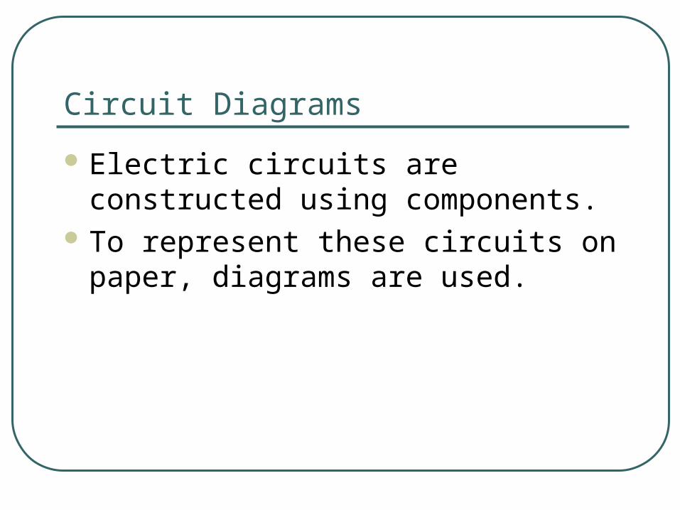
Circuit Diagrams
Electric circuits are constructed using components.
To represent these circuits on paper, diagrams are used.

The 4 Basic Circuit Elements
There are 4 basic circuit elements:
1. Energy sourcesa. Voltage sources
b. Current sources
2. Resistors
3. Inductors
4. Capacitors
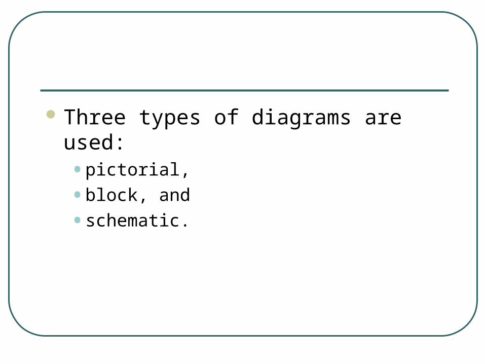
Three types of diagrams are used: • pictorial,
• block, and
• schematic.

Schematic circuit symbols

Pictorial Diagrams Help visualize circuits by showing
components as they actually appear.

Block Diagrams Circuit is broken into blocks, each
representing a portion of the circuit.

Schematic Diagrams
ENTC 4350
COMPONENTS

Voltage and Current

Atomic Theory
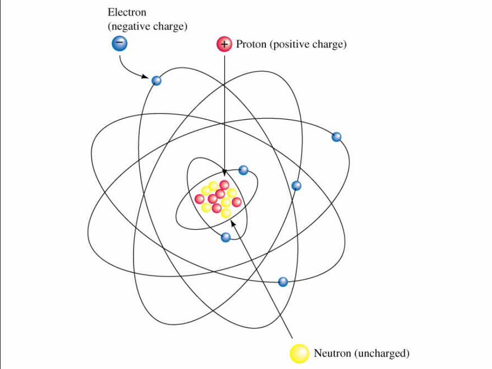
An atom consists of a nucleus of protons and neutrons surrounded by a group of orbiting electrons.
• Electrons have a negative charge, protons have a positive charge.
• In its normal state, each atom has an equal number of electrons and protons.

Atomic Theory
Electrons orbit the nucleus in discrete orbits called shells.
These shells are designated by letters K, L, M, N, etc.
Only certain numbers of electrons can exist within any given shell.

Atomic Theory
The outermost shell of an atom is called the valence shell.
The electrons in this shell are called valence electrons.
No element can have more than eight valence electrons.
The number of valence electrons affects its electrical properties.

Conductors
Materials that have large numbers of free electrons are called conductors.
• Metals are generally good conductors because they have few loosely bound valence electrons.
• Silver, gold, copper, and aluminum are excellent conductors.

Insulators
Materials that do not conduct because their valence shells are full or almost full are called insulators.
• Glass, porcelain, plastic, and rubber are good insulators.
• If high enough voltage is applied, an insulator will break down and conduct.

Semiconductors
Semiconductors have half-filled valence shells and are neither good conductors nor good insulators.
• Silicon and germanium are good semiconductors.
• They are used to make transistors, diodes, and integrated circuits.
Electrical Charge
Objects become charged when they have an excess or deficiency of electrons.
• An example is static electricity.
• The unit of charge is the coulomb.
• 1 coulomb = 6.24 × 1024 electrons.

Voltage
When two objects have a difference in charges, we say they have a potential difference or voltage between them.
• The unit of voltage is the volt.
• Thunderclouds have hundreds of millions of volts between them.
Voltage
A difference in potential energy is defined as voltage.
• The voltage between two points is one volt if it requires one joule of energy to move one coulomb of charge from one point to another.
• V = Work/Charge
• Voltage is defined between points.

I
EV b V a
l
• A model of a straight wire of length l and cross-sectional area A. • A potential difference of Vb – Va is maintained
across the conductor, setting up an electric field E.
• This electric field produces a current that is proportional to the potential difference.
A
lR

Current
The movement of charge is called electric current.
• The more electrons per second that pass through a circuit, the greater the current.
• Current is the rate of flow of charge.

E lectron
I
+
+-
-
+
-
(a) (b)
Electric current within a conductor. • (a) Random movement of electron generates no
current.
• (b) A net flow of electrons generated by an external force.

Current
The unit of current is the ampere (A).
• One ampere is the current in a circuit when one coulomb of charge passes a given point in one second.
• Current = Charge/time
• I = Q/t

Current If we assume current flows from the
positive terminal of a battery, we say it has conventional current flow.• In metals, current actually flows in the
negative direction.
• Conventional current flow is used in this course.
• Alternating current changes direction cyclically.

Batteries
Alkaline Carbon-Zinc Lithium Nickel-Cadmium Lead-Acid Primary batteries cannot be recharged,
secondary can

Battery Capacity
The capacity of a battery is specified in amp-hours.
• Life = capacity/current drain
• Battery with 200Ah – supplies 20A for 10h
• The capacity of a battery is affected by discharge rates, operating schedules, temperatures, and other factors.

Other Voltage Sources
Electronic Power Supplies Solar Cells Thermocouples DC Generators AC generators

How to Measure Voltage
Measure voltage by placing voltmeter leads across the component.
• The red lead is the positive lead; the black lead is the negative lead.
• If leads are reversed, you will read the opposite polarity.

Voltage measurement

How to Measure Current
The current you wish to measure must pass through the meter.
• You must open the circuit and insert the meter.
• Connect with correct polarity.

Current measurement
Break the circuit

Fuses and Circuit Breakers
Protect equipment or wiring against excessive current.
Fuses use a metallic element which melts. Slow-blow and fast-blow fuses. When the current exceeds the rated value of a
circuit breaker, the magnetic field produced by the excessive current operates a mechanism that trips open a switch.

Resistance
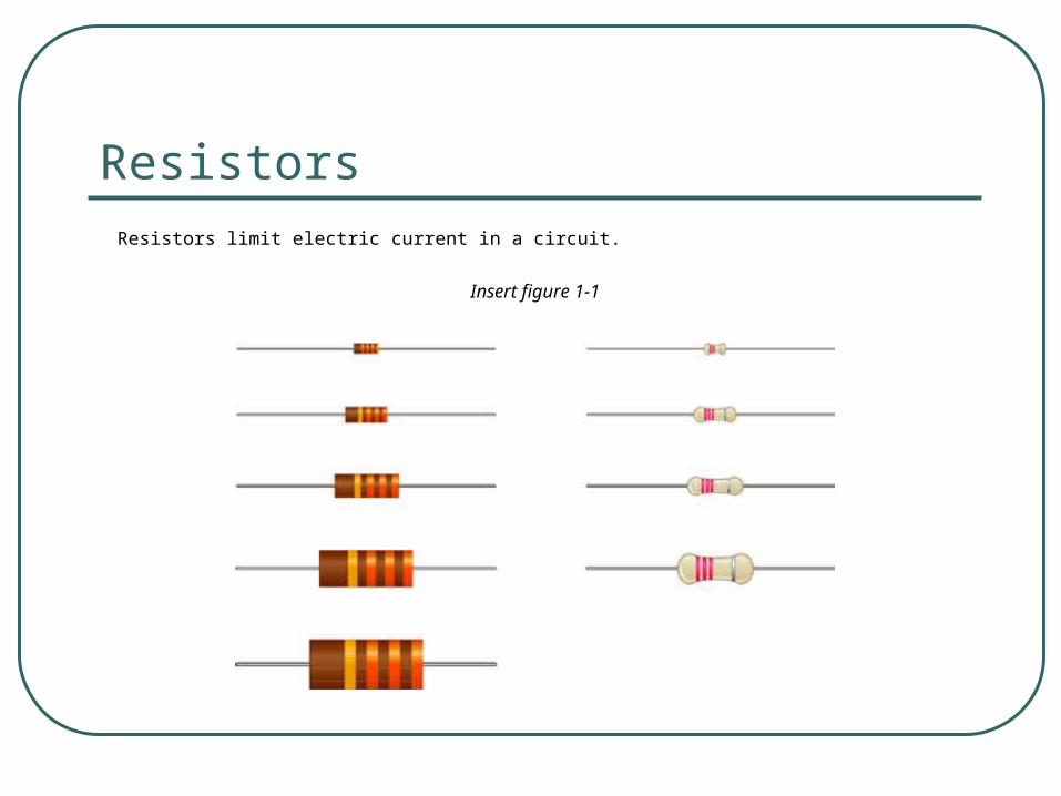
ResistorsResistors limit electric current in a circuit.
Insert figure 1-1

Resistors
A resistor is a two terminal circuit element that has a constant ratio of the voltage across its terminals to the current through its terminals.
The value of the ratio of voltage to current is the defining characteristic of the resistor.
In many cases a light bulb can be modeled with a resistor.

Resistors – Definition and Units
A resistor obeys the expression
where R is the resistance. If something obeys this expression,
we can think of it, and model it, as a resistor.
This expression is called Ohm’s Law. The unit ([Ohm] or []) is named for Ohm, and is equal to a [Volt/Ampere].
IMPORTANT: use Ohm’s Law only on resistors. It does not hold for sources.
To a first-order approximation, the body can modeled as a resistor. Our goal will be to avoid applying large voltages across our bodies, because it results in large currents through our body. This is not good.
R
R
vR
i
+
R
viR -

RX=#[]
vX
iX
-+
Schematic Symbol for Resistors
The schematic symbols that we use for resistors are shown here.
This is intended to indicate that the schematic symbol can be labeled either with a variable, like RX, or a value, with some number, and units. An example might be 390[]. It could also be labeled with both.
XX
X
vR
i

Resistor Polarities
There is no corresponding polarity to a resistor. You can flip it end-for-end, and it will behave the same way.

If the reference current is in the direction of the reference voltage drop (Passive Sign Convention), then…
RX=#[]
vX
iX
-+
Getting the Sign Right with Ohm’s Law
XX
X
vR
i

Resistance of Conductors
Resistance of material is dependent on several factors
• Type of Material
• Length of the Conductor
• Cross-sectional area
• Temperature A
lR

Type of Material
Differences at the atomic level of various materials will cause variations in how the collisions affect resistance.
• These differences are called the resistivity.
• We use the symbol .
• Units are ohm-meters.

Length
The resistance of a conductor is directly proportional to the length of the conductor.
• If you double the length of the wire, the resistance will double.
= length, in meters.

Area
The resistance of a conductor is inversely proportional to the cross-sectional area of the conductor.• If the cross-sectional area is doubled, the
resistance will be one half as much.
• A = cross-sectional area, in m2.
Resistance Formula
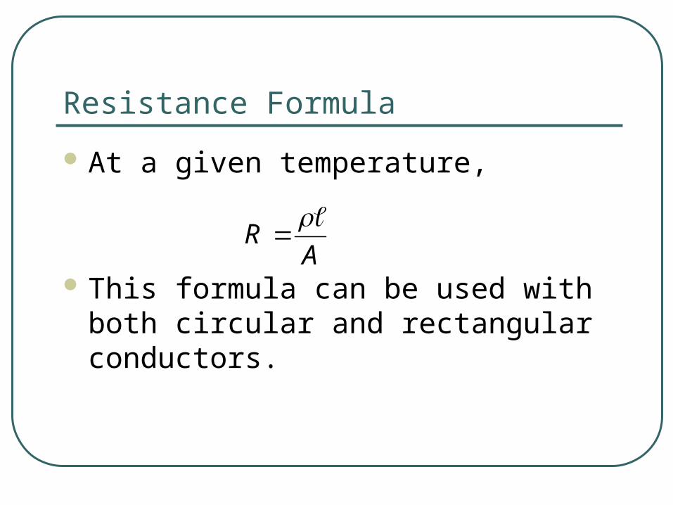
At a given temperature,
This formula can be used with both circular and rectangular conductors.
AR

Temperature Effects
For most conductors, an increase in temperature causes an increase in resistance.
• This increase is relatively linear.
• In semiconductors, an increase in temperature results in a decrease in resistance.
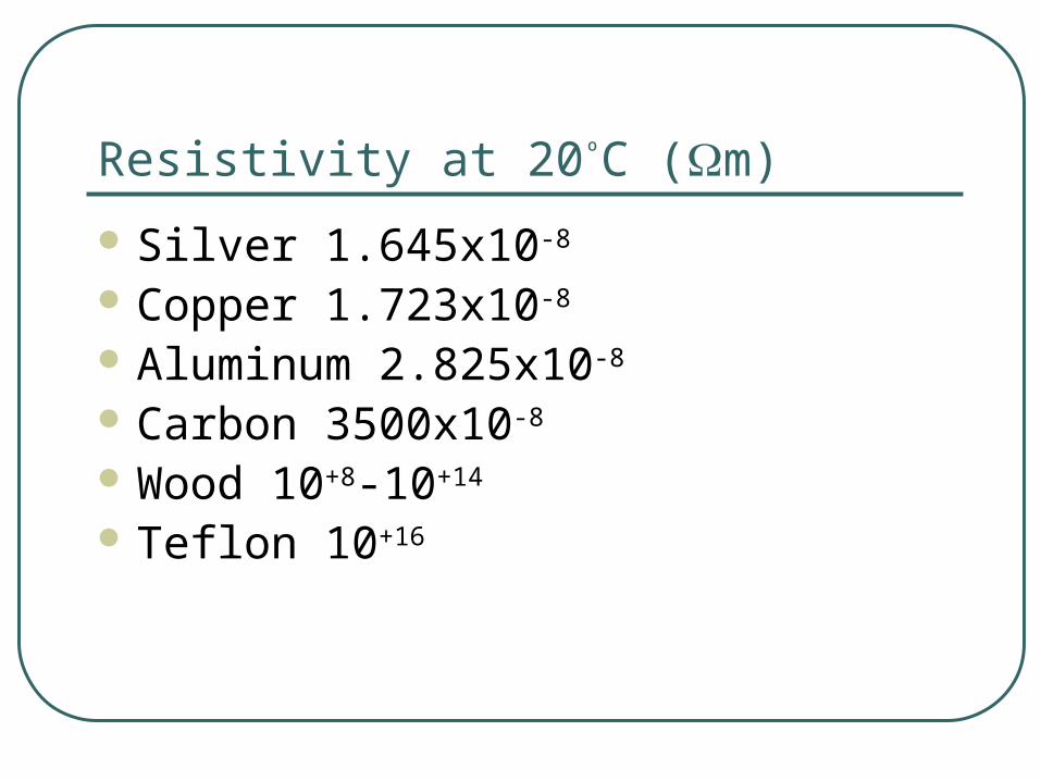
Resistivity at 20ºC (m)
Silver 1.645x10⁻⁸
Copper 1.723x10⁻⁸
Aluminum 2.825x10⁻⁸
Carbon 3500x10-8
Wood 10+8-10+14
Teflon 10+16
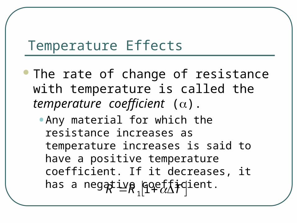
Temperature Effects
The rate of change of resistance with temperature is called the temperature coefficient ().
• Any material for which the resistance increases as temperature increases is said to have a positive temperature coefficient. If it decreases, it has a negative coefficient.
TRR 11

Temperature effect on resistance

Temperature coefficients (ºC)-1 at 20ºC
Silver 0.0038 Copper 0.00393 Aluminum 0.00391 Tungsten 0.00450 Carbon –0.0005 Teflon 10+16

Fixed Resistors
Resistances essentially constant. Rated by amount of resistance,
measured in ohms. Also rated by power ratings, measured in
watts.

Fixed Resistors
Different types of resistors are used for different applications.
• Molded carbon composition
• Carbon film
• Metal film
• Metal Oxide
• Wire-Wound
• Integrated circuit packages

Variable Resistors
Used to adjust volume, set level of lighting, adjust temperature.
• Have three terminals.
• Center terminal connected to wiper arm.
• Potentiometers
• Rheostats

Color Code
Colored bands on a resistor provide a code for determining the value of resistance, tolerance, and sometimes the reliability.

F irs t d ig it (A )
Second d ig it (B )
M ultip lie r (C )
T olerance (D )
• The colored bands that are found on a resistor can be used to determine its resistance.
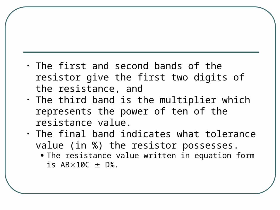
• The first and second bands of the resistor give the first two digits of the resistance, and
• The third band is the multiplier which represents the power of ten of the resistance value.
• The final band indicates what tolerance value (in %) the resistor possesses. • The resistance value written in equation form is
AB10C D%.

Color Number Tolerance (%)
Black 0
Brown 1
Red 2
Orange 3
Yellow 4
Green 5
Blue 6
Violet 7
Gray 8
White 9
Gold –1 5%
Silver –2 10%
Colorless 20%
• The color code for resistors.
•Each color can indicate a first or second digit, a multiplier, or, in a few cases, a tolerance value.

Measuring Resistance
Remove all power sources to the circuit.• Component must be isolated from rest of the
circuit.
Connect probes across the component. • No need to worry about polarity.
Useful to determine shorts and opens.

Thermistors
A two-terminal transducer in which the resistance changes with change in temperature.
• Applications include electronic thermometers and thermostatic control circuits for furnaces.
• Have negative temperature coefficients.

Photoconductive Cells
Two-terminal transducers which have a resistance determined by the amount of light falling on them.
• May be used to measure light intensity or to control lighting.
• Used as part of security systems.

Diodes
Semiconductor device that conducts in one direction only.
• In forward direction, has very little resistance.
• In reverse direction, resistance is very high - essentially an open circuit.

Varistors
Resistor which is sensitive to voltage.
• Have a very high resistance when the voltage is below the breakdown value.
• Have a very low resistance when the voltage is above the breakdown value.• Used in surge protectors.

Conductance and conductivity
The measure of a material’s ability to allow the flow of charge.• Conductance is the reciprocal of
resistance.
• G = 1/R
• Unit is siemens S.
• Conductivity =1/
• Unit is siemens/meter S/m.

Superconductors
At very low temperatures, resistance of some materials goes to almost zero.• This temperature is called the critical
temperature.
Meissner Effect - When a superconductor is cooled below its critical temperature, magnetic fields may surround but not enter the superconductor.

Ohm’s Law, Power,
and Energy

Ohm’s Law
The current in a resistive circuit is directly proportional to its applied voltage and inversely proportional to its resistance.• I = E/R; I = V/R
E
I R

E
I R
E
I R
E = I R I = E/R
E
I R
R = E/I

For a fixed resistance, doubling the voltage doubles the current.
For a fixed voltage, doubling the resistance halves the current.

Ohm’s Law
Ohm’s Law may also be expressed as E = IR and R = E/I
Express all quantities in base units of volts, ohms, and amps or utilize the relationship between prefixes.


Ohm’s Law in Graphical Form
The relationship between current and voltage is linear.
Open Circuits
Current can only exist where there is a conductive path.
When there is no conductive path we refer to this as an open circuit.
If I = 0, then Ohm’s Law gives R = E/I = E/0 infinity• An open circuit has infinite resistance.

Short circuit
If resistance R = 0 exists between two points we refer to this as a short-circuit
If R = 0, then Ohm’s law gives I = E/0 infinity• Never short-circuit a voltage source, infinitely
large current will destroy the circuit, injuries can result
• We often assume that the internal resistance of an ammeter is zero – never connect it across a voltage source.

Voltage Symbols
For voltage sources electromotive force emf, use uppercase E.
For load voltages, use uppercase V.
• Since V = IR, these voltages are sometimes referred to as IR or voltage drops.

Voltage Polarities
The polarity of voltages across resistors is of extreme importance in circuit analysis.
Place the plus sign at the tail of the current arrow.

Current Direction
We normally show current out of the plus terminal of a source.
If the actual current is in the direction of its reference arrow, it will have a positive value.
If the actual current is opposite to its reference arrow, it will have a negative value.

Current Direction
The following are two representations of the same current:

Why do we have to worry about the sign in Everything?
This is one of the central themes in circuit analysis. The polarity, and the sign that goes with that polarity, matters. The key is to find a way to get the sign correct every time.
This is why we need to define reference polarities for every voltage and current.
This is why we need to take care about what relationship we have used to assign reference polarities (passive sign convention and active sign convention).

Voltage Sources
A voltage source is a two-terminal circuit element that maintains a voltage across its terminals.
The value of the voltage is the defining characteristic of a voltage source.
Any value of the current can go through the voltage source, in any direction. The current can also be zero. The voltage source does not “care about” current. It “cares” only about voltage.

Voltage Sources – Ideal and Practical
A voltage source maintains a voltage across its terminals no matter what you connect to those terminals.
We often think of a battery as being a voltage source. For many situations, this is fine. Other times it is not a good model. A real battery will have different voltages across its terminals in some cases, such as when it is supplying a large amount of current.
As we have said, a voltage source should not change its voltage as the current changes.
We sometimes use the term ideal voltage source for our circuit elements, and the term practical voltage source for things like batteries. We will find that a more accurate model for a battery is an ideal voltage source in series with a resistor.

Current Sources
A current source is a two-terminal circuit element that maintains a current through its terminals.
The value of the current is the defining characteristic of the current source.
Any voltage can be across the current source, in either polarity. It can also be zero. The current source does not “care about” voltage. It “cares” only about current.

Current Sources - Ideal A current source maintains a current
through its terminals no matter what you connect to those terminals.
While there will be devices that reasonably model current sources, these devices are not as familiar as batteries.
We sometimes use the term ideal current source for our circuit elements, and the term practical current source for actual devices. We will find that a good model for these devices is an ideal current source in parallel with a resistor.

Voltage and Current Polarities
Previously, we have emphasized the important of reference polarities of currents and voltages.
Notice that the schematic symbols for the voltage sources and current sources indicate these polarities.
The voltage sources have a “+” and a “–” to show the voltage reference polarity. The current sources have an arrow to show the current reference polarity.

ENTC 4350
Kirchhoff’s Laws

Overview of this Part
In this part of the module, we will cover the following topics:
Some Basic Assumptions Kirchhoff’s Current Law (KCL) Kirchhoff’s Voltage Law (KVL)

Some Fundamental Assumptions – Wires
Although you may not have stated it, or thought about it, when you have drawn circuit schematics, you have connected components or devices with wires, and shown this with lines.
Wires can be modeled pretty well as resistors. However, their resistance is usually negligibly small.
We will think of wires as connections with zero resistance. Note that this is equivalent to having a zero-valued voltage source.
This picture shows wires used to connect electrical components. This particular way of connecting components is called wirewrapping, since the ends of the wires are wrapped around posts.

Some Fundamental Assumptions – Nodes
A node is defined as a point where two or more components are connected.
The key thing to remember is that we connect components with wires. It doesn’t matter how many wires are being used; it only matters how many components are connected together.
+
-vA
RC
RD
iBRF
RE

How Many Nodes?
To test our understanding of nodes, let’s look at the example circuit schematic given here.
How many nodes are there in this circuit?
+
-vA
RC
RD
iBRF
RE

How Many Nodes – Correct Answer
In this schematic, there are three nodes. These nodes are shown in dark blue here.
Some students count more than three nodes in a circuit like this. When they do, it is usually because they have considered two points connected by a wire to be two nodes.
+
-
vA
RC
RD
iB
RF
RE

How Many Nodes – Wrong Answer
In the example circuit schematic given here, the two red nodes are really the same node. There are not four nodes.
Remember, two nodes connected by a wire were really only one node in the first place.
+
-
vA
RC
RD
iB
RF
RE
Wire connecting two nodes means that these are really a single node.

Some Fundamental Assumptions – Closed Loops
A closed loop can be defined in this way: Start at any node and go in any direction and end up where you start. This is a closed loop.
Note that this loop does not have to follow components. It can jump across open space. Most of the time we will follow components, but we will also have situations where we need to jump between nodes that have no connections.
+
-
vA
RC
RD
iB
RF
RE
vX
+
-

How Many Closed Loops To test our
understanding of closed loops, let’s look at the example circuit schematic given here.
How many closed loops are there in this circuit?
+
-
vA
RC
RD
iB
RF
RE
vX
+
-

How Many Closed Loops – An Answer
There are several closed loops that are possible here. We will show a few of them, and allow you to find the others.
The total number of simple closed loops in this circuit is 13.
Finding the number will not turn out to be important. What is important is to recognize closed loops when you see them.
+
-
vA
RC
RD
iB
RF
RE
vX
+
-

+
-
vA
RC
RD
iB
RF
RE
vX
+
-
Closed Loops – Loop #1 Here is a loop we will
call Loop #1. The path is shown in red.

+
-
vA
RC
RD
iB
RF
RE
vX
+
-
Here is Loop #2. The path is shown in red.
Closed Loops – Loop #2

+
-
vA
RC
RD
iB
RF
RE
vX
+
-
Closed Loops – Loop #3 Here is Loop #3. The
path is shown in red.
Note that this path is a closed loop that jumps across the voltage labeled vX. This is still a closed loop.

+
-
vA
RC
RD
iB
RF
RE
vX
+
-
Closed Loops – Loop #4 Here is Loop #4. The
path is shown in red. Note that this path is a
closed loop that jumps across the voltage labeled vX. This is still a closed loop. The loop also crossed the current source. Remember that a current source can have a voltage across it.

+
-
vA
RC
RD
iB
RF
RE
vX
+
-
A Not-Closed Loop The path is shown in
red here is not closed. Note that this path
does not end where it started.

Kirchhoff’s Current Law (KCL)
With these definitions, we are prepared to state Kirchhoff’s Current Law:
The algebraic (or signed) summation of currents through a closed surface must equal zero.

I1I2
I3
3 A
I = ?
(a ) (b )
6 A
Figure 2.5 (a) Kirchhoff’s current law states that the sum of the currents entering a node is 0. (b) Two currents entering and one “negative entering”, or leaving.
I = 9 A

Kirchhoff’s Current Law (KCL) – Some notes.
The algebraic (or signed) summation of currents through any closed surface must equal zero.
This definition is often stated as applying to nodes. It applies to any closed surface. For any closed surface, the charge that enters must leave somewhere else. A node is just a small closed surface. A node is the closed surface that we use most often. But, we can use any closed surface, and sometimes it is really necessary to use closed surfaces that are not nodes.
This definition essentially means that charge does not build up at a connection point, and that charge is conserved.

Current Polarities
Again, the issue of the sign, or polarity, or direction, of the current arises. When we write a Kirchhoff Current Law equation, we attach a sign to each reference current polarity, depending on whether the reference current is entering or leaving the closed surface. This can be done in different ways.
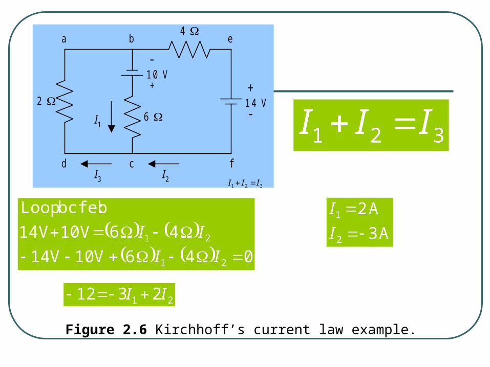
+
-10 V
I1
2 6
4
I3 I2
-
+14 V
a b e
d c f
Figure 2.6 Kirchhoff’s current law example.
321 III
Kirchhoff’s Current Law (KCL) – a Systematic Approach
The algebraic (or signed) summation of currents through any closed surface must equal zero.
For this set of material, we will always assign a positive sign to a term that refers to a reference current that leaves a closed surface, and a negative sign to a term that refers to a reference current that enters a closed surface.
For most students, it is a good idea to choose one way to write KCL equations, and just do it that way every time. The idea is this: If you always do it the same way, you are less likely to get confused about which way you were doing it in a certain equation.

Kirchhoff’s Current Law (KCL) – an Example
For this set of material, we will always assign a positive sign to a term that refers to a current that leaves a closed surface, and a negative sign to a term that refers to a current that enters a closed surface.
In this example, we have already assigned reference polarities for all of the currents for the nodes indicated in darker blue.
For this circuit, and using my rule, we have the following equation:
+
-
vA
RC
RD
iB
RF
RE
iA
iB
iC
iE
iD
0A C D E Bi i i i i- - -

Kirchhoff’s Current Law (KCL) – Example Done Another Way
Some prefer to write this same equation in a different way; they say that the current entering the closed surface must equal the current leaving the closed surface. Thus, they write :
+
-
vA
RC
RD
iB
RF
RE
iA
iB
iC
iE
iD
0A C D E Bi i i i i- - -
A D B C Ei i i i i • Compare this to the equation that we wrote in the last slide:
• These are the same equation. Use either method.

Kirchhoff’s Voltage Law (KVL)
Now, we are prepared to state Kirchhoff’s Voltage Law:
The algebraic (or signed) summation of voltages around a closed loop must equal zero.

Kirchhoff’s Voltage Law (KVL) – Some notes.
The algebraic (or signed) summation of voltages around a closed loop must equal zero.
This applies to all closed loops. While we usually write equations for closed loops that follow components, we do not need to. The only thing that we need to do is end up where we started.
This definition essentially means that energy is conserved. If we move around, wherever we move, if we end up in the place we started, we cannot have changed the potential at that point.

Voltage Polarities
Again, the issue of the sign, or polarity, or direction, of the voltage arises. When we write a Kirchhoff Voltage Law equation, we attach a sign to each reference voltage polarity, depending on whether the reference voltage is a rise or a drop. This can be done in different ways.

Kirchhoff’s Voltage Law (KVL) – a Systematic Approach
The algebraic (or signed) summation of voltages around a closed loop must equal zero.
For this set of material, we will always go around loops clockwise. We will assign a positive sign to a term that refers to a reference voltage drop, and a negative sign to a term that refers to a reference voltage rise.
For most students, it is a good idea to choose one way to write KVL equations, and just do it that way every time. The idea is this: If you always do it the same way, you are less likely to get confused about which way you were doing it in a certain equation.
(At least we will do this for planar circuits. For nonplanar circuits, clockwise does not mean anything. If this is confusing, ignore it for now.)

I R
+ -V
(a)
V 1 V 2
+ -10
I
+ -20
V S = 30 V
R 1 R 2
(b)
Figure 2.4 (a) The voltage drop created by an element has the polarity of + to – in the direction of current flow. (b) Kirchhoff’s voltage law.
+
-
vA
RC
RD
iB
RF
RE
vX
+
-
vF
+
-
vE- +
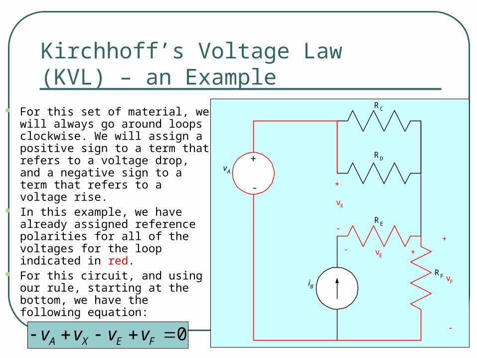
Kirchhoff’s Voltage Law (KVL) – an Example
For this set of material, we will always go around loops clockwise. We will assign a positive sign to a term that refers to a voltage drop, and a negative sign to a term that refers to a voltage rise.
In this example, we have already assigned reference polarities for all of the voltages for the loop indicated in red.
For this circuit, and using our rule, starting at the bottom, we have the following equation:
0A X E Fv v v v- -

+
-
vA
RC
RD
iB
RF
RE
vX
+
-
vF
+
-
vE- +
Kirchhoff’s Voltage Law (KVL) – Notes
For this set of material, we will always go around loops clockwise. We will assign a positive sign to a term that refers to a voltage drop, and a negative sign to a term that refers to a voltage rise.
Some students like to use the following handy mnemonic device: Use the sign of the voltage that is on the side of the voltage that you enter. This amounts to the same thing.
0A X E Fv v v v- -
As we go up through the voltage source, we enter the negative sign first. Thus, vA has a negative sign in the equation.

+
-
vA
RC
RD
iB
RF
RE
vX
+
-
vF
+
-
vE- +
Kirchhoff’s Voltage Law (KVL) – Example Done Another Way
Some textbooks, and some students, prefer to write this same equation in a different way; they say that the voltage drops must equal the voltage rises. Thus, they write the following equation:
0A X E Fv v v v- -
X F A Ev v v v Compare this to the equation that we wrote in the last slide:
These are the same equation. Use either method.

This is a very important question. In general, it boils down to the old rule that you need the same number of equations as you have unknowns.
Speaking more carefully, we would say that to have a single solution, we need to have the same number of independent equations as we have variables.
At this point, we are not going to introduce you to the way to know how many equations you will need, or which ones to write. It is assumed that you will be able to judge whether you have what you need because the circuits will be fairly simple. Later we will develop methods to answer this question specifically and efficiently.
How many of these equations do I need to write?

How many more laws are we going to learn?
This is another very important question. Until, we get to inductors and capacitors, the answer is, none.
Speaking more carefully, we would say that most of the rules that follow until we introduce the other basic elements, can be derived from these laws.
At this point, you have the tools to solve many, many circuits problems. Specifically, you have Ohm’s Law, and Kirchhoff’s Laws. However, we need to be able to use these laws efficiently and accurately. We will spend some time in ENTC 4350 learning techniques, concepts and approaches that help us to do just that.

How many f’s and h’s are there in Kirchhoff?
This is another not-important question. But, we might as well learn how to spell Kirchhoff. Our approach might be to double almost everything, but we might end up with something like Kirrcchhooff.
We suspect that this is one reason why people typically abbreviate these laws as KCL and KVL. This is pretty safe, and seems like a pretty good idea to us.

Example #1
Let’s do an example to test out our new found skills.
In the circuit shown here, find the voltage vX and the current iX.
R4=20[]
R3=100[]
vS1=3[V]
+
-
vX
+
-
iX

Example #1 – Step 1
The first step in solving is to define variables we need.
In the circuit shown here, we will define v4 and i3.
R4=20[]
R3=100[]
vS1=3[V]
+
-
vX
+
-
iX
v4+ -
i3

Example #1 – Step 2
The second step in solving is to write some equations. Let’s start with KVL.
R4=20[]
R3=100[]
vS1=3[V]
+
-
vX
+
-
iX
v4+ -
i3
1 4
4
0, or
3[V] 0.S X
X
v v v
v v
- -

Example #1 – Step 3
Now let’s write Ohm’s Law for the resistors. R4=
20[]
R3=100[]
vS1=3[V]
+
-
vX
+
-
iX
v4+ -
i3
4 4
3 3
, and
.X
X
v i R
v i R
-
Notice that there is a sign in Ohm’s Law.

Example #1 – Step 4
Next, let’s write KCL for the node marked in violet.
3
3
0, or
.X
X
i i
i i
-
Notice that we can write KCL for a node, or any other closed surface.
R4=20[]
R3=100[]
vS1=3[V]
+
-
vX
+
-
iX
v4+ -
i3

Example #1 – Step 5
We are ready to solve.
We have substituted into our KVL equation from other equations.
R4=20[]
R3=100[]
vS1=3[V]
+
-
vX
+
-
iX
v4+ -
i3
3[V] 20[ ] 100[ ] 0, or
3[V]25[mA].
120[ ]
X X
X
i i
i
- - - - -

Example #1 – Step 6
Next, for the other requested solution.
We have substituted into Ohm’s Law, using our solution for iX.
R4=20[]
R3=100[]
vS1=3[V]
+
-
vX
+
-
iX
v4+ -
i3
3 3 3 , or
25[mA] 100[ ] 2.5[V].X X
X
v i R i R
v
-
- -

ENTC 4350
SUMMARY

(c) Voltmeters/Ammeters/Ohmmeters
A voltmeter is used to measure voltage in a circuit.
An ammeter is used to measure current in a circuit.
An ohmmeter is used to measure resistance.

Summary
Resistors limit electric current. Power supplies provide current and
voltage. Voltmeters measure voltage. Ammeters measure current. Ohmmeters measure resistance. Digital Multimeters (DMM) measure
voltage, current and resistance.

Summary
KVL—The algebraic sum of voltages around a closed loop is zero.• The voltage rises equal the voltage drops.
KCL—The algebraic sum of currents at a node is zero.• Current entering a node equals current
leaving a node.

Summary
Scientific notation expresses a number as one digit to the left of the decimal point times a power of ten.
Engineering notation expresses a number as one, two or three digits to the left of the decimal point times a power of ten that is a multiple of 3.
Metric symbols represent powers of 10 that are multiples of 3.

A voltage source is a two-terminal circuit element that maintains a voltage across its terminals.
The value of the voltage is the defining characteristic of a voltage source.
Any value of the current can go through the voltage source, in any direction. The current can also be zero. The voltage source does not “care about” current. It “cares” only about voltage.

Color Code for ElectronicsColor Number Tolerance (%)
Black 0
Brown 1
Red 2
Orange 3
Yellow 4
Green 5
Blue 6
Violet 7
Gray 8
White 9
Gold –1 5%
Silver –2 10%
Colorless 20%