BME280 Environmental Sensor User Manual fileAfter configuring, reboot your Raspberry Pi sudo reboot...
16
BME280 Environmental Sensor BME280 Environmental Sensor User Manual OVERVIEW The BME280 is as combined digital humidity, pressure and temperature sensor. Its small dimensions, low power consumption, high precision and stability allow the implementation in environmental monitor, whether forecast, altitude detection and IOT application. FEATURES ⚫ Support I2C interface, I2C device address could be set by changing I/O or welds ⚫ Supports SPI interface. Default I2C, you can change to SPI by change I/O ⚫ Integrated Level convert circuit, compatible with 3.3V/5V ⚫ Provide examples and user guide (Raspberry Pi/Arduino/STM32) SPECIFICATION Operating voltage: 5V/3.3V Interface: I2C/SPI Temperature range: -40~85°C (Resolution 0.1°C, tolerance ±1°C) Humidity range: 0~100%rh (Resolution 0.008%RH, tolerance ±1°C) Pressure range: 300~1100hPa(Resolution 0.18Pa, tolerance ±1hPa) Dimensions: 27mmx20mm Holes size: 2.0mm
Transcript of BME280 Environmental Sensor User Manual fileAfter configuring, reboot your Raspberry Pi sudo reboot...
BME280 Environmental Sensor
BME280 Environmental Sensor
User Manual
OVERVIEW
The BME280 is as combined digital humidity, pressure and temperature sensor. Its
small dimensions, low power consumption, high precision and stability allow the
implementation in environmental monitor, whether forecast, altitude detection and
IOT application.
FEATURES
⚫ Support I2C interface, I2C device address could be set by changing I/O or welds
⚫ Supports SPI interface. Default I2C, you can change to SPI by change I/O
⚫ Integrated Level convert circuit, compatible with 3.3V/5V
⚫ Provide examples and user guide (Raspberry Pi/Arduino/STM32)
SPECIFICATION
Operating voltage: 5V/3.3V
Interface: I2C/SPI
Temperature range: -40~85°C (Resolution 0.1°C, tolerance ±1°C)
Humidity range: 0~100%rh (Resolution 0.008%RH, tolerance ±1°C)
Pressure range: 300~1100hPa(Resolution 0.18Pa, tolerance ±1hPa)
Dimensions: 27mmx20mm
Holes size: 2.0mm

BME280 Environmental Sensor
INTERFACES
I2C
PIN Arduino STM32 RASPBERRY Description
VCC 3.3V/5V 3.3V /5V 3.3V /5V Power
GND GND GND GND Ground
SDA A4 PB7 SDA I2C Data
SCL A5 PB6 SCL I2C Clock
ADDR NC/GND NC/GND NC/GND
Address Select (High by default):
High:address is 0x77
Low:address is 0x76
CS NC NC NC NC
SPI:
PIN Arduino STM32 RASPBERRY Description
VCC 3.3V /5V 3.3V /5V 3.3V /5V Power
GND GND GND GND Ground
MOSI D11 PA7 MOSI SPI Data input
SCK D13 PA5 SCK SPI Clock input
MISO D12 PA6 MISO SPI Data output
CS D10 PB6 27 SPI chip select, Low active

BME280 Environmental Sensor
WORKING WITH EXAMPLES
WORKING WITH RASPBERRY PI
INSTALL LIBRARIES
To use examples we provide, you need to first install WiringPi library, or it could
be be used normally. About how to install WiringPi library, you can visit the page:
Libraries installation for RPi for details.
EXAMPLE DOWNLOAD
Visit Our Wiki and find the page of BME280 Environmental Sensor, download the
demo code.
Extract it to get the folders as below:

BME280 Environmental Sensor
Copy Raspberry folder to your Raspberry Pi. You can copy it to the root of the TF card
which you use for your Raspberry Pi.
CONNECTION
1. Enable I2C or SPI interface first, open configuration page with the command:
sudo raspi-config
2. Enable the interface separately.
- For SPI: Choose Interfacing Options-> SPI -> Yes
- For I2C (default): Choose Interfacing Options->I2C->Yes
3. After configuring, reboot your Raspberry Pi
sudo reboot
4. After rebooting, you can check if I2C or SPI module has been enabled with
command (If there are I2C or SPI information printed, modules are started):
lsmod

BME280 Environmental Sensor
5. Connet BME280 Environmental Sensor (called BME280) to your Raspberry Pi
according to the I2C table above.
6. The address of I2C device is 0x77 by default. If you want to change it to 0x76, yu
can connect ADDR to GND.
7. Install I2C-tools tool, for I2C devices detecting
sudo apt-get install i2c-tools
8. You can query I2C devices with command:
i2cdetect -y 1
If there is 77 printed (76 if you change the address), it means that BME280 has
connected to Raspberry Pi normally.
Note: Please make sure that there are not other I2C devices which has the same
address as BME280. For SPI connection, you can refer to the SPI table above.
BME280 Environmental Sensor
RUNNING DEMO CODE
1. Connecting BME280 as above
2. Enter directory of BME280-Environmental-Sensor-Demo-Code (which is included
in the folder we copied before):
cd BME280-Environmental-Sensor-Demo-Code
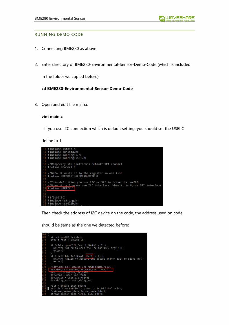
3. Open and edit file main.c
vim main.c
- If you use I2C connection which is default setting, you should set the USEIIC
define to 1:
Then check the address of I2C device on the code, the address used on code
should be same as the one we detected before:

BME280 Environmental Sensor
- If you use SPI connection. You should change the USEIIC define to 0 on main.c:
4. Save and exit. Then re-compile the demo code:
sudo make clean
sudo make
5. Running the demo code:
sudo ./bme280
Note: if there are not any data outputted after running the demo code or get wrong
data, please check the hardware connection and address used.

BME280 Environmental Sensor
WORKING WITH ARDUINO
1. Open Arduino folder (from the one we download), Copy folder BME280-Arduino-
Library to Libraries directory of IDE, which locates on installation directory of
Arduino IDE.
2. Open Arduino IDE, Choose File->Examples-> BME280_Libreay->bme280test to
open the demo code.
3. Connect BME280 to Arduino according to Interfaces
- By default, communication interface is I2C with device address 0x77
- If you want to use SPI interface, you need to change USEIIC to 0 on demo code
4. If you want to change the device address to 0x76, you could connect ADDR to
ND, and change the BME280_ADDRES value on Adafruit.h of demo code:

BME280 Environmental Sensor
5. If you want to get correct altitude data, you should first measure the atmosphere
pressure of local sea level and then change the define of SEALEVELPRESSURE_HPA
6. Then compile and download to your Arduino board.
7. Open Serial monitor and set the baud rate to 11520
Note: if there are not any data outputted after running the demo code or get wrong
data, please check the hardware connection and address used
BME280 Environmental Sensor
WORKIGN WITH STM32
1. Open STM32 project which is under STM32 directory.
2. Connect BME280 to STM32 board according to Interfaces
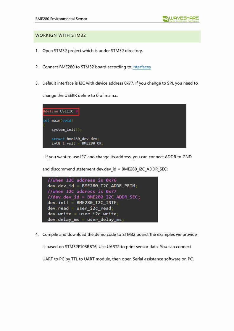
3. Default interface is I2C with device address 0x77. If you change to SPI, you need to
change the USEIIR define to 0 of main.c:
- If you want to use I2C and change its address, you can connect ADDR to GND
and discommend statement dev.dev_id = BME280_I2C_ADDR_SEC:
4. Compile and download the demo code to STM32 board, the examples we provide
is based on STM32F103RBT6, Use UART2 to print sensor data. You can connect
UART to PC by TTL to UART module, then open Serial assistance software on PC,

BME280 Environmental Sensor
default 115200 8N1:
Note: if there are not any data outputted after running the demo code or get wrong
data, please check the hardware connection and address used.

BME280 Environmental Sensor
CODE ANALYSIS
Libraries used In demo code is official library Bosch Sensortec:
https://github.com/BoschSensortec/BME280_driver
For SPI, its initial code:
struct bme280_dev dev;
int8_t rslt = BME280_OK;
/* Sensor_0 interface over SPI with native chip select line */
dev.dev_id = 0;
dev.intf = BME280_SPI_INTF;
dev.read = user_spi_read;
dev.write = user_spi_write;
dev.delay_ms = user_delay_ms;
rslt = bme280_init(&dev);
For I2C, its initial code:
struct bme280_dev dev;
int8_t rslt = BME280_OK;
dev.dev_id = BME280_I2C_ADDR_PRIM;
dev.intf = BME280_I2C_INTF;
dev.read = user_i2c_read;
dev.write = user_i2c_write;
dev.delay_ms = user_delay_ms;
rslt = bme280_init(&dev);
bme280_dev is BME280 device structure provided by official library, could be used to
initialize and obtain data. For different platform we should realize the functions below:
user_i2c_read()
user_i2c_write()
user_spi_read()
user_spi_write()
user_delay_ms()

BME280 Environmental Sensor
And then transfer function pointers of these functions to bem280_dev structure.
The function to read BME280 data is:
int8_t stream_sensor_data_forced_mode(struct bme280_dev *dev)
int8_t stream_sensor_data_normal_mode(struct bme280_dev *dev)
Print function:
void print_sensor_data(struct bme280_data *comp_data)
The read/write function of I2C and SPI:
void user_delay_ms(uint32_t period)
{
/*
* Return control or wait,
* for a period amount of milliseconds
*/
}
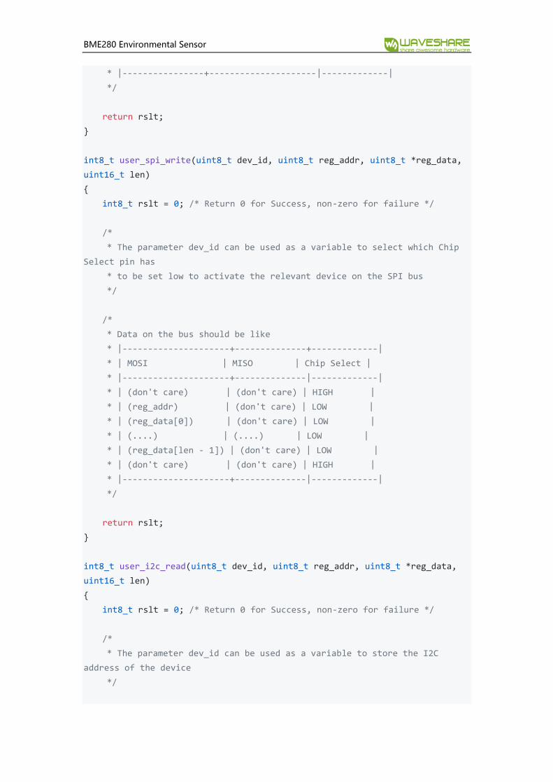
int8_t user_spi_read(uint8_t dev_id, uint8_t reg_addr, uint8_t *reg_data,
uint16_t len)
{
int8_t rslt = 0; /* Return 0 for Success, non-zero for failure */
/*
* The parameter dev_id can be used as a variable to select which Chip
Select pin has
* to be set low to activate the relevant device on the SPI bus
*/
/*
* Data on the bus should be like
* |----------------+---------------------+-------------|
* | MOSI | MISO | Chip Select |
* |----------------+---------------------|-------------|
* | (don't care) | (don't care) | HIGH |
* | (reg_addr) | (don't care) | LOW |
* | (don't care) | (reg_data[0]) | LOW |
* | (....) | (....) | LOW |
* | (don't care) | (reg_data[len - 1]) | LOW |
* | (don't care) | (don't care) | HIGH |
BME280 Environmental Sensor
* |----------------+---------------------|-------------|
*/
return rslt;
}
int8_t user_spi_write(uint8_t dev_id, uint8_t reg_addr, uint8_t *reg_data,
uint16_t len)
{
int8_t rslt = 0; /* Return 0 for Success, non-zero for failure */
/*
* The parameter dev_id can be used as a variable to select which Chip
Select pin has
* to be set low to activate the relevant device on the SPI bus
*/
/*
* Data on the bus should be like
* |---------------------+--------------+-------------|
* | MOSI | MISO | Chip Select |
* |---------------------+--------------|-------------|
* | (don't care) | (don't care) | HIGH |
* | (reg_addr) | (don't care) | LOW |
* | (reg_data[0]) | (don't care) | LOW |
* | (....) | (....) | LOW |
* | (reg_data[len - 1]) | (don't care) | LOW |
* | (don't care) | (don't care) | HIGH |
* |---------------------+--------------|-------------|
*/
return rslt;
}
int8_t user_i2c_read(uint8_t dev_id, uint8_t reg_addr, uint8_t *reg_data,
uint16_t len)
{
int8_t rslt = 0; /* Return 0 for Success, non-zero for failure */
/*
* The parameter dev_id can be used as a variable to store the I2C
address of the device
*/

BME280 Environmental Sensor
/*
* Data on the bus should be like
* |------------+---------------------|
* | I2C action | Data |
* |------------+---------------------|
* | Start | - |
* | Write | (reg_addr) |
* | Stop | - |
* | Start | - |
* | Read | (reg_data[0]) |
* | Read | (....) |
* | Read | (reg_data[len - 1]) |
* | Stop | - |
* |------------+---------------------|
*/
return rslt;
}
int8_t user_i2c_write(uint8_t dev_id, uint8_t reg_addr, uint8_t *reg_data,
uint16_t len)
{
int8_t rslt = 0; /* Return 0 for Success, non-zero for failure */
/*
* The parameter dev_id can be used as a variable to store the I2C
address of the device
*/
/*
* Data on the bus should be like
* |------------+---------------------|
* | I2C action | Data |
* |------------+---------------------|
* | Start | - |
* | Write | (reg_addr) |
* | Write | (reg_data[0]) |
* | Write | (....) |
* | Write | (reg_data[len - 1]) |
* | Stop | - |
* |------------+---------------------|
*/
return rslt;
}

BME280 Environmental Sensor
The basic flows to read BME280 data are:
Step1: Initialize for OS and peripheral
Step2: Realize Read, Write and Delay functions (I2C and SPI), and assignment the
functions pointer to bme280_dev structure as publics, then transfer the pointer of
structure to initialization function int8_t bme280_init(struct bme280_dev *dev).
Initialize BME280 device.
Step3: Calling int8_t stream_sensor_data_forced_mode(struct bme280_dev *dev) or
int8_t stream_sensor_data_normal_mode(struct bme280_dev *dev) to get data of
BME280 sensor and print them to console or PC.


![[Conference] Building Websites that Matter - Agent Reboot Boston, Agent Reboot DC, Agent Reboot Austin](https://static.fdocuments.net/doc/165x107/558a27d9d8b42a98578b465c/conference-building-websites-that-matter-agent-reboot-boston-agent-reboot-dc-agent-reboot-austin.jpg)