Bluetooth Robot Controller - Florida Gulf Coast...
26
Bluetooth Robot Controller Neven Skoro <[email protected]> Mentor: Janusz Zalewski CEN 4516 Computer Networks Date Modified: November 20 th 2006 http://satnet.fgcu.edu/~nskoro
Transcript of Bluetooth Robot Controller - Florida Gulf Coast...

Bluetooth Robot Controller
Neven Skoro
Mentor: Janusz Zalewski
CEN 4516 Computer Networks
Date Modified: November 20th 2006
http://satnet.fgcu.edu/~nskoro
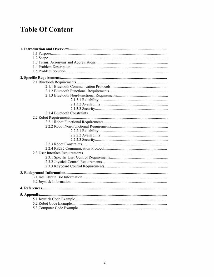
Table Of Content
1. Introduction and Overview......................................................................................................1.1 Purpose.........................................................................................................................1.2 Scope............................................................................................................................1.3 Terms, Acronyms and Abbreviations...........................................................................1.4 Problem Description.....................................................................................................1.5 Problem Solution..........................................................................................................
2. Specific Requirements.............................................................................................................. 2.1 Bluetooth Requirements...............................................................................................
2.1.1 Bluetooth Communication Protocols...........................................................2.1.2 Bluetooth Functional Requirements............................................................. 2.1.3 Bluetooth Non-Functional Requirements.....................................................
2.1.3.1 Reliability........................................................................ 2.1.3.2 Availability ..................................................................... 2.1.3.3 Security............................................................................
2.1.4 Bluetooth Constraints................................................................................... 2.2 Robot Requirements.....................................................................................................
2.2.1 Robot Functional Requirements................................................................... 2.2.2 Robot Non-Functional Requirements...........................................................
2.2.2.1 Reliability........................................................................ 2.2.2.2 Availability ..................................................................... 2.2.2.3 Security............................................................................
2.2.3 Robot Constraints……………………......................................................... 2.2.4 RS232 Communication Protocol.................................................................
2.3 User Interface Requirements........................................................................................2.3.1 Specific User Control Requirements............................................................2.3.2 Joystick Control Requirements....................................................................2.3.3 Keyboard Control Requirements..................................................................
3. Background Information..........................................................................................................3.1 IntelliBrain Bot Information........................................................................................3.2 Joystick Information....................................................................................................
4. References..................................................................................................................................
5. Appendix.................................................................................................................................... 5.1 Joystick Code Example............................................................................................... 5.2 Robot Code Example...................................................................................................5.3 Computer Code Example.............................................................................................
2

Abstract:
In the world of automation, we want things to be to work independently without any
human interaction. We want computer servers to run without human control, we want our
cars, computers, phone, planes and other complicated systems built automatically without
too much hassle. Perhaps you would want your lawn moved by a robot, or maybe you would
want to remotely mow the lawn using your computer to control the lawn mower. This
project will inform you, the reader, how a secure Bluetooth communication between a robot
and a user is designed and implemented and most importantly why it works.
Machines are a big part of the world’s production, transportation and exploration.
Most of the people today are unaware of how much work is done by robots everyday for
example in car manufacturing facilities and military operations. Mobile robots shall
probably be the most important machines in the future. Already, mobile robots are being
used to explore distant planets as well as for just simple house hold work such as mowing
the lawn or vacuuming. This report focuses on a Bluetooth Communication which was
established between the Intellibrain Robot and a Personal Computer. This specific design
and implementation would work with most two-wheel differential robots that have a serial
port available on their main boards and can run Java Virtual Machine.
3
1. Introduction and Overview
1.1.Purpose
The main purpose of this project is to develop a remote user interface to control a
robot via a wireless technology. There is a need to communicate with the robot remotely in
order to control the robot movements and pass critical data both ways. The current IR
controls are not good enough because the robot does not have an IR transmitter but only a
receiver, meaning that the communication is one way. The IR communication works only in
line of direct sight and any objects in the way will obstruct the communication.
Bluetooth communication will enable us to control the robot up to 100 meters
without the need for direct sight which means that the robot could be located behind a wall
or some other object and the communication would not be lost.
1.2.Scope
This system will deal with the basic robot movement functions, as well as user
interface, Bluetooth communication, serial RS232 communication between the robot and the
Bluetooth module, and RS232 communication between the PC and the Bluetooth module.
Full implementation of the code both for the robot and the computer shall be
developed in this project.
1.3.Terms, Acronyms & Abbreviations
- IR - Infra Red
- RS232 - Serial Communication Standard
- ACL - Asynchronous connection link
- GFSK - Gaussian Frequency shifting
4

- DTE - Data Terminal Equipment
- DCE – Data Carrier Equipment
- CTS – Clear to Send
- DTR – Data Terminal Ready
- DCD - Data Carrier Detect
- RTS – Request To Send
- GND - Ground
- DSR – Data Set Ready
- RI – Ring Indicator
- ASYNCHRONOUS – a communications system in which data transmission may start at
any time and is indicated by a start bit
- SYNCHRONOUS – a communications system in which sending and receiving of data
is fixed by time-clock intervals
- ROBOT – IntelliBrain-Bot Robot
- BLUETOOTH MODULE – Firefly Serial Bluetooth Module Class 1
1.4.Problem Description
There is a need for a remote robot controller that will enable the two way communication
between the user and the robot. This controller must be wireless in order to give the robot its
movement freedom. The current IR controller works only one way because the robot does not have
its own transmitter. The IR communication is very limited because the transmitter has to be directly
pointed to the receiver. With the Bluetooth technology we can have a two way communication
which works on radio frequency up to 100 meters in distance. Furthermore, we want to control the
5
robot with a user interface such as a joystick and keyboard. The robot could then pass the data such
as distance, speed, battery power, etc. back to the user. The user could then decide what he wants to
do with the robot according to the data received. The navigation system shall be relatively accurate
with no deviation higher than two centimeters. No robot is perfect, and it shall most likely never be
error free. Sometimes in robotics you have to accept close enough to be perfect.
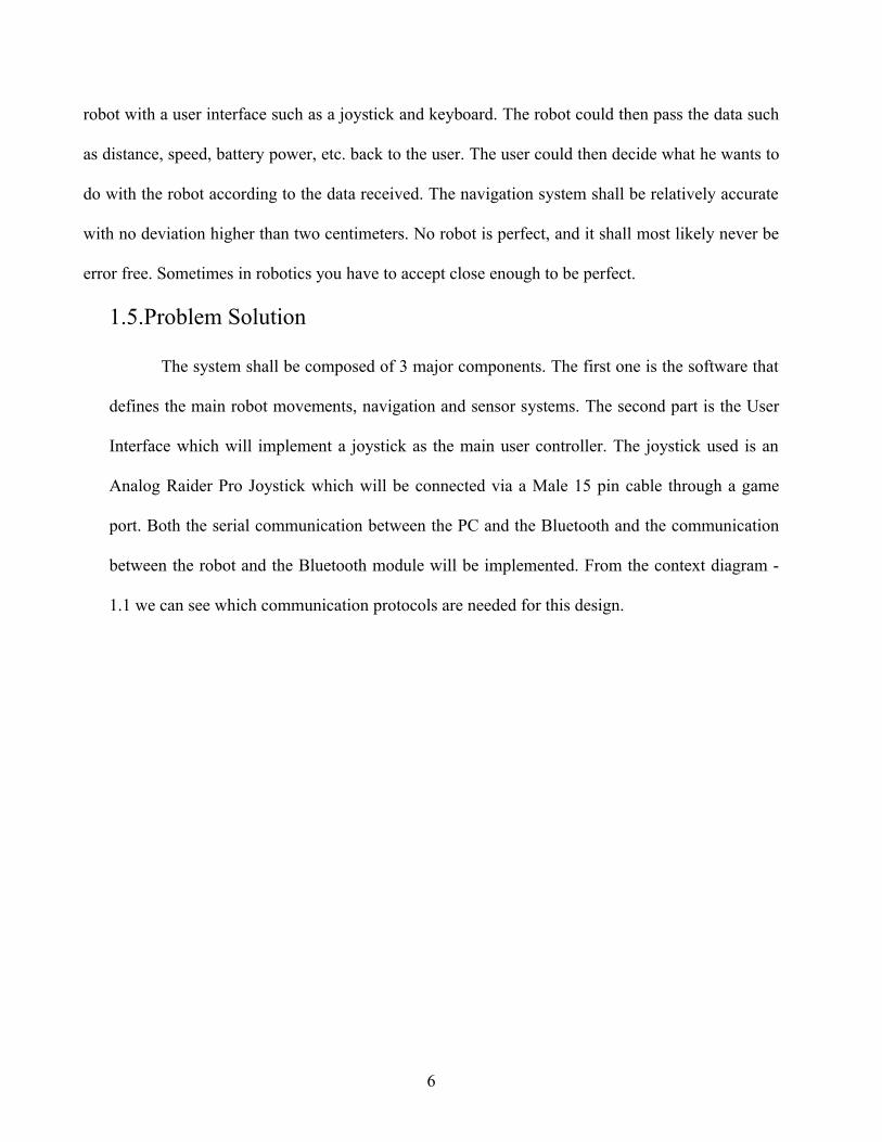
1.5.Problem Solution
The system shall be composed of 3 major components. The first one is the software that
defines the main robot movements, navigation and sensor systems. The second part is the User
Interface which will implement a joystick as the main user controller. The joystick used is an
Analog Raider Pro Joystick which will be connected via a Male 15 pin cable through a game
port. Both the serial communication between the PC and the Bluetooth and the communication
between the robot and the Bluetooth module will be implemented. From the context diagram -
1.1 we can see which communication protocols are needed for this design.
6
Fig 1.1 Context Diagram
The spoofing of the serial cables is required to make the connection between the robot
and the computer work. Bellow we can see the colors used in a regular serial cable for
corresponding pin. The standard RS232 cable has 9 pins which we can see from the table 1.3.
Most DCE devices only use pins 2, 3, 5 which are Receive, transmit and ground, respectively.
This makes at problem for the Bluetooth because it requires an active CTS and RTS signals in
order to know if the data was requested. To solve this problem I have connected pins 7 and 9 to
7

each other on the robot’s Bluetooth module so it always thinks data is ready to be received and
transmitted.
Fig 1.2 RS232 Serial Connections (Source: Zytrax.com)
Above we can see the solution to the problem. We can simply wire pins 1, 4 and 6
together so that the computer things it found the device looping back, DTS, DTR and DCD back
to itself. On the computer part of the connection I had to wire pins 1, 4 and 6 together because
the Bluetooth modules only use pins 2, 3, 5, 7, 9 and therefore it does not tell the computer if a
DCD device was detected on the other end. This term is know as “spoofing” the connection and
should be done very carefully.
On the robot side, I have connected the brown wire to the send pin, red to the receive
pin, yellow to the ground pin, and gray to the power pin. The corresponding pin to the colors
can be found in the coloring table bellow Figure 1.5.
8

Fig 1.3 RS232 cable pinout
Pin No.
Name Notes/Description
1 DCD Data Carrier Detect
2 RD Receive Data
3 TD Transmit Data
4 DTR Data Terminal Ready
5 SGND Ground
6 DSR Data Set Ready
7 RTS Request To Send
8 CTS Clear To Send
9 RI Ring Indicator
Fig 1.4 RS232 pinout table
Fig 1.5 RS232 cable colors (Source: maxstream.net)
9

Both Bluetooth modules have to be pre-programmed before use in order to set the
correct, baud rate, stop bits, parity, encryption and whether the device is master or a slave. There
are many more options which can be found in figure 1.6.
Fig 1.6 Bluetooth module options (source: Gridconnect.com)
A Bluetooth module can be programmed by connecting it to the computer via a serial
cable and running a communication program such as HyperTerminal on Windows OS or
MiniCom on Linux OS. To put the Bluetooth module into the configuration state it needs to be
plugged into the computer and then powered. After powering, a time count down will initiate
giving you 60 seconds to put it into configuration mode. Typing “$$$” into the terminal window
will access the Bluetooth configuration commands listed in table 1.6 and 1.7. Exiting the
configuration mode is done by typing “—“. The table 1.7 simply shows the advance
10
configuration options for the respective modules.
Fig 1.7 Advance Options (Source: GridConnect.com)
The Bluetooth modules required some further hardware modifications. The placement of
the inner jumpers was changed to accommodate the communication needs. Because each
Bluetooth device requires CTS and RTS signals I jumped pins 1 and 3, 2 and 4, 5 and 6, 7 and 8,
9 and 10 respectively on the female module on the computer end. On the robot (male) Bluetooth
module I have jumped pins 1 and 2, 3 and 4, 9 and 10 respectively.
2. Specific Requirements
2.1.Bluetooth Requirements
2.1.1.Bluetooth Communication Protocols
11
The Bluetooth module use Gaussian Frequency shifting GFSK and work at the ISM
band of 2.4 GHz. The modules are divided into Master and Slave. The master module looks
for any slave modules in range and saves their address and connects to it. The master is in
charge of setting the frequency hopping sequence which insures that no other wireless
devices are disturbed. Both devices need to agree on the BAUD rate, parity, stop bits, and
flow control in order to send bits from the PC to the Robot and back. In this design the
Bluetooth modules are simply extending the serial cable wirelessly. The Bluetooth devices
used in this project are Class 1 which use 100mW (20 dBm) and have a maximum range of
100 meters.
Bluetooth communication is much different than the RS232 communication, but it
can resemble one. It uses Asynchronous Connectionless links (ACL) for its data
communications. ACL link sends data at irregular intervals whenever data is available.
Some of the ACL link ensures data accuracy by checking for errors and re sending data if
needed.
The Access code, header and a payload are embedded into a packet which is
transmitted. Therefore the slave device will match its access code to the incoming packet.
The control information is contained in the header part of the packet and the actual data
message is contained in the payload part of the packet. Bluetooth protocol uses four different
access codes such as Channel Access Code (CAC), Devices Access Code (DAC), General
Inquiry Access Code (GIAC) and Dedicated Inquiry Access Code (DIAC). CAC is used by
all devices that are exchanging data. DAC is used for paging a device, GIAC is used for the
inquiry procedures and DIAC is used for used for specified range of the inquiry access code.
12

Fig 2.1 Data Protocol
The above figure shows the Bluetooth stack protocol compared to the OSI reference
model. The Bluetooth can be in many different states such as the standby, inquiry state,
inquiry scan, page state, page scan, active connection, connection hold, connection stiff and
connection park. Each Bluetooth device can only be in one state at one time.
13

Fig 2.2 Bluetooth Message Sequence
The diagram 1.3 shows how the Bluetooth processes the inquiry in the message
sequence. The Inquiry device sends an ID packet with the access code, and the inquiry
scanning device listens for the request. After it hears the first request it automatically goes
into a delay period before it starts listening again. When it hears the second request it sends
the Frequency hop sequence back to the inquiry device. More than one device can respond
to an inquiry but they respond randomly at different times therefore they do not interfere
with each other.
14
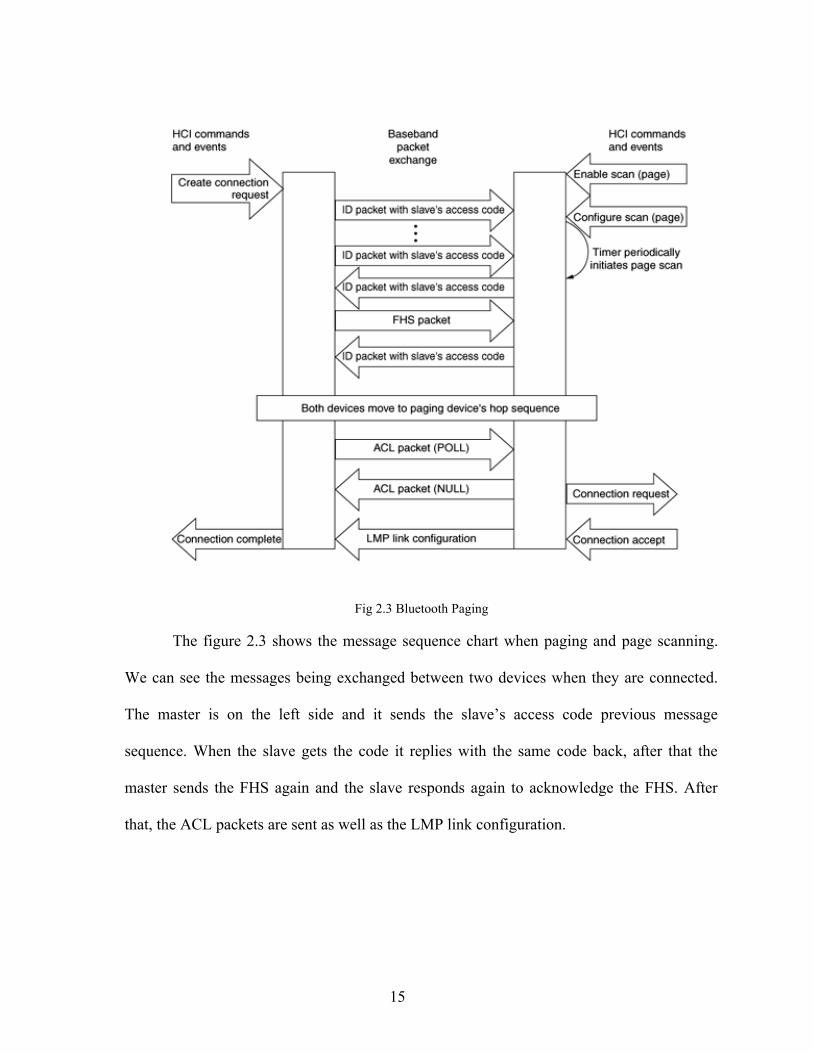
Fig 2.3 Bluetooth Paging
The figure 2.3 shows the message sequence chart when paging and page scanning.
We can see the messages being exchanged between two devices when they are connected.
The master is on the left side and it sends the slave’s access code previous message
sequence. When the slave gets the code it replies with the same code back, after that the
master sends the FHS again and the slave responds again to acknowledge the FHS. After
that, the ACL packets are sent as well as the LMP link configuration.
15

2.1.2.Bluetooth Functional Requirements
- Bluetooth female module shall receive a byte from the Computer Serial port and transmit
it to the male module connected to the robot serial port
- Bluetooth connection shall work both ways
2.1.3.Bluetooth Non-Functional Requirements
2.1.3.1.Reliability
- The Bluetooth connection shall not experience any system major crashes or errors
2.1.3.2.Availability
- The Bluetooth connection shall be available 100% of the time if in range of 100 meters.
2.1.3.3.Security
- The Bluetooth connection shall not allow any other slave devices to connect to the
master and receive data.
- The Bluetooth connection shall use data encryption.
2.1.4.Bluetooth Constraints
- The Bluetooth modules are limited to maximum transfer rate of 115200Kb/s and to the
distance of 100 meters.
2.2. Robot Requirements
2.2.1.Robot Functional Requirements
- Robot moves shall respond to joystick positions
- Robot shall be able to detect objects in its pathway
- Robot shall store the path x and y coordinates in a double array variable
16

- Robot shall be able to follow its previous memorized path
2.2.2.Robot Non-Functional Requirements
2.2.2.1.Reliability
- Robot shall respond to joystick movement within fewer than 500 milliseconds
- Robot shall not hit any objects in its pathway
- Robot shall not miss its destination within more than 2 inches
2.2.2.2.Availability
- Robot shall respond to user’s commands at all times
2.2.2.3.Security
- Robot shall not allow access to its commands to more than one Bluetooth module
2.2.3.Robot Constraints
- Robot cannot run more than 10 threads successfully
- Robot runs on an Micro controller that has 14.7 MHz processing power
- Robot has 128 flash program memory
- Robot has 132K RAM available
- Robot has 4K bytes of EEPROM available
2.2.4.RS232 communication protocols
The serial connection used in this project to connect the PC and the Bluetooth
module is Asynchronous Serial Transmission (UART). The sender and the receiver do
not agree on the timing signals between the bits of data being send, rather they use a
17

start bit and a stop bit. The start bit tells the receiver where the data begins using the
little endian order meaning that the least significant bit is sent first. The time between
each bit is the same for all the bits, and the receiver just determines whether the bit is 1
or 0. The sender checks the clock to see if it is time to send the next word but it does
not however know when the receiver has gotten the data. Parity may be used for simple
checking and flow control but they will not be used in this project because the
Bluetooth modules do not support flow of control.
An important thing to notice is that when the communication is idle,
meaning that no data is being sent, the RS232 will be transmitting continuous 1 values.
Therefore a start bit always has a value of 0 and a stop bit has a value of 1. The
standard voltage being sent is +12VDC or -12VDC but some low power devices allow
+5VDC and -5VDC which are still acceptable but in this case the cable length should
be short. In case that there is no electricity present in the circuit, a signal called a break
is being sent. This signal needs to be longer than the complete byte being sent plus the
start, stop and parity bits.
The RS232 specification describes two types of connection ends: Data
Terminal Equipment (DTE) and the Data Carrier Equipment (DCE). By standard
convention DTE is usually the computer and DCE is a modem. But it’s important to
remember the Bluetooth module does not work with modems. Modem here is just a
reference to a device being connected to the pc.
2.3.User Interface Requirements
2.3.1.Specific User Control Requirements
- The user shall be able to control the robot movements via a joystick
18

- The user shall be able to give commands to the robot via a keyboard
- The user shall be able to switch between joystick and keyboard controls
- The user shall be able to start and terminate a connection
- The user shall be able to receive battery charge information from the robot
- The user shall not be able to run the robot into an object
2.3.2.Joystick Control Requirements
- The joystick shall send x and y coordinates to the computer
- The joystick shall send the states of 2 of its buttons
- The joystick maximum and minimum y coordinates shall be 9 and -9 respectively
- The joystick maximum and minimum x coordinates shall be 9 and -9 respectively
2.3.3.Keyboard Control Requirements
- The user shall be able to enter x and y coordinates from the keyboard which shall be sent
to the robot
- The user shall be able to control robot movement by pressing letters w, s, a, d and q for
forward, backwards, left, right and stop respectively
3. Background Information
3.1.IntelliBrain Bot Information
Most of the robots built today are two-wheel differential meaning that all of the robots
movement is accomplished with just one set of wheels. The IntelliBrain bot is composed of the
IntelliBrain main board that takes the energy from 4 AA batteries to power the two servo motor
ports as well as other sensor ports. This robot has the following components attached to it’s main
19

board: an LCD display a couple of push buttons, a beeper, an SRF04 sonar range sensor; two
wheels that are attached to the servo motors, a set of GP2D12 range sensors and two QRB1134
infrared photo reflector sensors used for wheel encoding as well as line sensing. All of this
hardware sits on a well-built Boe-Bot chassis developed by Parallax.
The robot runs on java virtual machine that supports multi threading which is essential for
this project because we need to have multiple objects running at the same time. This IntelliBrain bot
uses RoboJDE Java development environment software that is used to design, build and upload the
program to the main board of the robot. This software comes with the API specification of classes
and methods that have already been developed for public use. The program is uploaded to the robot
via a serial cable. The robot’s main board consists of 10 Digital inputs and outputs, an infrared
receiver, 3 IC ports, a buzzer, a 16x2 LCD display, 2 servo ports, 7 analog/digital inputs, a power
switch, 2 push buttons, a thumbwheel, a host Interface (RS-232, 115.2K baud) and a wall brick
power connector.
The robot runs on an Atmel Atmega128 Micro controller that has 14.7 MHz, 128 flash program
memory, 132K RAM and 4K bytes of EEPROM. The API specification notes that the flash memory
has a limited life of 10,000 writes and therefore should be used sparingly, while the 4K of
EEPROM is estimated to have a lifetime of 100,000 writes. The Java Virtual Machine and the
bootstrap loader use 4K bytes of Random Access Memory (RAM). The infrared receiver works at
38 kHz and is compatible with most television remotes; this receiver could also be used for
communication between two robots. The bootstrap leader is software on the robot responsible for
downloading the virtual machine to the robot and changing the host port baud rate.
3.2.Joystick Information
20

The joystick used in this project was an older joystick that used a game port rather
than USB. Modern computers do not come with game port anymore therefore, to overcome
this problem I have installed a midi sound card (which has a 15 pin input on it) into the
computer PCI port. The joystick can be connected to the midi card which is then recognized
by the Operating System as a game port.
(male connector on joystick cable)
.-----------------------.\ 8 7 6 5 4 3 2 1 /
\ 15 14 13 12 11 10 9 /~~~~~~~~~~~~~~~~~~~
1 XY1 (+5v)2 Switch 1
3 X14 Ground (for switch 1)5 Ground (for switch 2)
6 Y17 Switch 2
8 N.C.9 XY2 (+5v)10 Switch 3
11 X212 Ground (for switch 3&4) *
13 Y214 Switch 415 N.C. *
Fig 2.4 joystick pinout
The joystick port is located on the ISA bus I/O address 201h and can be accessed by
the CPU to read and write to the port. When data is sent to the port, the joystick initializes its
position measurements but the data sent to the joystick is not relevant and it is not saved
anywhere.
21

4. References
[1] Julia Layton and Curt Franklin, “How Bluetooth Works”,
URL: http://electronics.howstuffworks.com/bluetooth.htm
[2] Hac, Anna, “Mobile Telecommunications Protocols for Data Networks”, Publication:
Chichester, West Sussex, Hoboken, NJ John Wiley & Sons, Ltd. (UK), 2003
[3] Ridgesoft LLC Inc, “IntelliBrain Guide”, PO BOX 482, Pleasanton, CA,
URL: http://ridgesoft.com/intellibrain/IntelliBrainGuide.pdf
[4] Grid Connect, “Firefly Bluetooth Serial Manual”, June 27th 2006, 1841 Centre Point
Circle, Suite 143 Naperville, IL 60563,
URL: http://site.gridconnect.com/docs/PDF/Firefly_800314_c.pdf
[5] Frank Durda, “Serial and UART Tutorial”, January, 13th 1996
URL: http://www.freebsd.org/doc/en_US.ISO8859-1/articles/serial-uart/index.html
5. Appendix
5.1 Joystick programming example
INT 15 - BIOS - JOYSTICK SUPPORT (XT after 11/8/82,AT,XT286,PS) AH = 84h DX = subfunction 0000h read joystick switches Return: AL bits 7-4 = switch settings 0001h read positions of joysticks Return: AX = X position of joystick A BX = Y position of joystick A CX = X position of joystick B DX = Y position of joystick BReturn: CF set on error AH = status 80h invalid command (PC,PCjr) 86h function not supported (other) CF clear if successful
Notes: if no game port is installed, subfunction 0000h returns AL=00h (all switches open) and subfunction 0001h returns AX=BX=CX=DX=0000h a 250kOhm joystick typically returns 0000h-01A0h
22

5.2 Robot-Code example
// setting up connection try { SerialPort comPort = IntelliBrain.getCom2();
//Serial Parameters comPort.setSerialPortParams(115200,SerialPort.DATABITS_8,SerialPort.STOPBITS_1,SerialPort.PARITY_NONE);
InputStream inputStream = comPort.getInputStream(); OutputStream outputStream = comPort.getOutputStream();
// clear screendisplay.print(0, "");display.print(1, "");
// Setting buffer byte [] buf = new byte[128];}
public static void moveRobot(int i, int i2) {
mLeftMotor.setPower(i); // Turn left motor mRightMotor.setPower(i2); // Turn right motor
}
5.3 Computer-Code example
/* * Author: Neven Skoro * Date Modified: November 18th 2006 * FLORIDA GULF COAST UNIVERSITY * http://satnet.fgcu.edu/~nskoro * * */
// SerialComm.java
package com.centralnexus.input;
import javax.comm.CommPortIdentifier;import javax.comm.PortInUseException;import javax.comm.SerialPort;import javax.comm.UnsupportedCommOperationException;import java.io.*;import java.util.Enumeration;
public class SerialComm {
static boolean portFound; static String[] defaultPorts; static Enumeration portList; static CommPortIdentifier portId; static String defaultPort; static SerialPort serialPort; static InputStream inputStream; static OutputStream outputStream; static BufferedReader in;
23
static Joystick joy2;static final int AXIS_X = 0;
/** Constant for axisValues */ static final int AXIS_Y = 1; /** Constant for axisValues */ public SerialComm() { try{ portId= CommPortIdentifier.getPortIdentifier("COM3"); } catch(Exception e){System.out.println(" no port " + e); } System.out.println("found port "); try { serialPort = (SerialPort) portId.open("serial", 50); } catch (PortInUseException e) {System.out.println(e);}
try { serialPort.setSerialPortParams(115200, SerialPort.DATABITS_8, SerialPort.STOPBITS_1, SerialPort.PARITY_NONE); } catch (UnsupportedCommOperationException e) {} System.out.println(serialPort.getFlowControlMode()); //OutputStream try { outputStream = serialPort.getOutputStream(); } catch (Exception e) {}
//ImputStream try { inputStream = serialPort.getInputStream(); } catch (IOException e) {} } public static byte [] charToByteArray( char c ){ byte [] twoBytes = { (byte)(c & 0xff), (byte)(c >> 8 & 0xff) }; System.out.println("char to byte " + twoBytes[0] + " " + twoBytes[1]); return twoBytes;}
public static void pushIt(byte b) {
try { outputStream.write(b); // outputStream.flush(); } catch (IOException ex) { System.out.println(ex.toString()); }}public static void pushIt(byte[] b) {
try { outputStream.write(b); // outputStream.flush(); } catch (IOException ex) { System.out.println(ex.toString()); } }public static void pushIt(byte b, byte b2) {
try { outputStream.write(b);
24
outputStream.write('\r'); outputStream.write(b2); outputStream.write('\r'); outputStream.flush(); } catch (IOException ex) { System.out.println(ex.toString()); }}public static byte[] intToBytes(int i) {
byte[] b = new byte[2]; int i1, i2;
if (i == 0) { b[0] = 0; b[1] = 0; } if (0 < i & i <= 255) { b[0] = (byte) i; b[1] = 0; } if (i > 255) { b[0] = (byte) (i % 256); b[1] = (byte) (i / 256); } if ( -255 <= i & i < 0) {
b[0] = (byte) (255 + i); b[1] = (byte) 255; } if (i < -255) {
b[0] = (byte) (255 + (i % 256)); b[1] = (byte) (255 + (i / 256)); } return b;}
public static void main(String args[]){ byte[] b = new byte[128];
int i=0; new SerialComm(); in = new BufferedReader(new InputStreamReader(System.in)); System.out.println("DTR" + serialPort.isDTR()); System.out.println("CTS" + serialPort.isCTS()); System.out.println("RTS" + serialPort.isRTS()); System.out.println("DSR" + serialPort.isDSR()); System.out.println("CD" +serialPort.isCD()); try{ joy2 = Joystick.createInstance(); } catch(IOException e){} while(true){ joy2.poll(); b[0] =((byte)-(joy2.getY()*10)); System.out.println("The " + 0 + " byte is " + b[0]); serialPort.setRTS(true); if (serialPort.isCTS()){ System.out.println("Clear to send!!!");
if (joy2.getY() < -0.8) // forward pushIt((byte)85);
25

else if (joy2.getY() > 0.8) // backwards pushIt((byte)84); else if (joy2.getX() < -0.8) // left pushIt((byte)83); else if (joy2.getX() > 0.8) // right pushIt((byte)82); else // stop pushIt((byte)89); }if (joy2.isButtonDown(1)){
System.out.println("Connection terminated..."); serialPort.close(); break;} if (joy2.isButtonDown(2)){
boolean flag =true; // Reading data from keyboard System.out.println("Please input a command: ");
while (flag){ try{
i = System.in.read(); } catch (IOException e){} if ((char)i == 'w') pushIt((byte)85); if ((char)i == 's') pushIt((byte)84); if ((char)i == 'a') pushIt((byte)83); if ((char)i == 'd') pushIt((byte)82); if ((char)i == 'q') pushIt((byte)89); if (i =='\t') flag = false; } } try{
System.out.println("input stream equals: " +inputStream.available()); if (inputStream.available() > 0) { System.out.println("inputstream is available"); byte [] buffer = new byte[128]; int length = inputStream.read(buffer); System.out.println("length of input is " + length); System.out.println("Input buffer is " + buffer.toString()); } } catch (IOException e) {System.out.println("error reading input" + e);}
try{ Thread.sleep(75); } catch (Throwable t){}
} } } // END OF FILE
26


![Smart Robot Arm Motion Using Computer Vision · robot arm are controlled according to a human arm’s movements using wireless connection and a vision system [10]. Two cameras, having](https://static.fdocuments.net/doc/165x107/5f116aea788d250e4b3e29f2/smart-robot-arm-motion-using-computer-vision-robot-arm-are-controlled-according.jpg)