BlueRadios ATMP Commands Rev 3.6.2.1.4.0 - Digi-Key Sheets/BlueRadios PDFs/ATMP... · User Guide...
103
Page 1 of 103 BlueRadios, Inc. Copyright © 2002-2008 BR-AT_COMMANDS-100 Rev. 3.6.2.1.4.0 7173 S. Havana Street, Suite 600 • Englewood, CO 80112 • Tel (303) 957-1003 • [email protected] www.BlueRadios.com User Guide For: ® Bluetooth ® Intelligent Serial Module ATMP Command Set Audio/Data Evaluation Board Pictured Above with Class1 BR-C40A Radio. By: , Inc. AT HOME. AT WORK. ON THE ROAD. USING BLUETOOTH WIRELESS TECHNOLOGY MEANS TOTAL FREEDOM FROM THE CONSTRAINTS AND CLUTTER OF WIRES IN YOUR LIFE. Subject matter contained herein is of highly sensitive nature and is confidential and proprietary to BlueRadios Incorporated, and all manufacturing, reproduction, use and sale rights pertaining to such subject matter are expressly reserved. The recipient, by accepting this material, agrees that this material will not be used, copied or reproduced in whole or in part nor its contents revealed in any manner to any person or other company except to meet the express purpose for which it was delivered. This document includes data that shall not be disclosed outside of your organization and shall not be duplicated, used, or disclosed, in whole or in part, for any purpose other than to evaluate this document. BlueRadios, Incorporated, proprietary information is subject to change without notice.
Transcript of BlueRadios ATMP Commands Rev 3.6.2.1.4.0 - Digi-Key Sheets/BlueRadios PDFs/ATMP... · User Guide...

Page 1 of 103
BlueRadios, Inc. Copyright © 2002-2008
BR-AT_COMMANDS-100 Rev. 3.6.2.1.4.0
7173 S. Havana Street, Suite 600 • Englewood, CO 80112 • Tel (303) 957-1003 • [email protected]
www.BlueRadios.com
User Guide
For:
® Bluetooth®
Intelligent Serial Module ATMP Command Set
Audio/Data Evaluation Board Pictured Above with Class1 BR-C40A Radio.
By:
, Inc.
AT HOME. AT WORK. ON THE ROAD. USING BLUETOOTH WIRELESS TECHNOLOGY MEANS TOTAL FREEDOM FROM THE CONSTRAINTS AND CLUTTER OF WIRES IN YOUR LIFE. Subject matter contained herein is of highly sensitive nature and is confidential and proprietary to BlueRadios Incorporated, and all manufacturing, reproduction, use and sale rights pertaining to such subject matter are expressly reserved. The recipient, by accepting this material, agrees that this material will not be used, copied or reproduced in whole or in part nor its contents revealed in any manner to any person or other company except to meet the express purpose for which it was delivered. This document includes data that shall not be disclosed outside of your organization and shall not be duplicated, used, or disclosed, in whole or in part, for any purpose other than to evaluate this document. BlueRadios, Incorporated, proprietary information is subject to change without notice.
Page 2 of 103
BlueRadios, Inc. Copyright © 2002-2008
BR-AT_COMMANDS-100 Rev. 3.6.2.1.4.0
7173 S. Havana Street, Suite 600 • Englewood, CO 80112 • Tel (303) 957-1003 • [email protected]
www.BlueRadios.com
REVISION HISTORY .................................................................................................................................................. 5
IMPORTANT NOTES - PLEASE READ PRIOR TO CONTINUING .......................................................................... 7
QUICK START GUIDE FOR EVALUATION KIT ....................................................................................................... 8
1 INTRODUCTION .................................................................................................................................................. 9
2 MULTI-POINT (MP) ARCHITECTURE .............................................................................................................. 16
2.1 USING MULTI-POINT MODE ........................................................................................................................................ 16
2.1.1 Receiving Data in Multi-Point Mode ..................................................................................................................... 16 2.1.2 Transmitting Data in Multi-Point Mode ................................................................................................................ 16
2.2 MULTIPOINT EXAMPLES ............................................................................................................................................. 17
2.3 REPEATER MODE ........................................................................................................................................................ 18
2.4 MESH MODE ............................................................................................................................................................... 18
2.5 MULTIPOINT TEST SCENARIOS .................................................................................................................................... 18
3 AT COMMANDS ................................................................................................................................................ 21
3.1 THE ATTENTION (AT) COMMAND PREFIX .................................................................................................................. 21
3.2 FIRMWARE VERSION ................................................................................................................................................... 21
3.3 RESETTING THE RADIO ............................................................................................................................................... 22
3.4 SET/GET RADIO INFORMATION ................................................................................................................................... 23
3.4.1 Get Status Information ........................................................................................................................................... 23 3.4.2 Boot Mode ............................................................................................................................................................. 28 3.4.3 Security Level ........................................................................................................................................................ 29 3.4.4 Maximum Number of Bluetooth Connections ....................................................................................................... 30 3.4.5 Set and Read Radio Name ..................................................................................................................................... 31 3.4.6 Set and Read Service Name for Local and Remote Devices ................................................................................. 32 3.4.7 Security PIN/Passkey Settings ............................................................................................................................... 33 3.4.8 Class of Device (COD) ......................................................................................................................................... 36 3.4.9 Write Memory Locations (S Registers) – Radio Configuration ............................................................................ 36 3.4.10 Read Memory Locations (S Registers) .............................................................................................................. 46
3.5 INQUIRY/CONNECT/DISCONNECT COMMANDS ........................................................................................................... 46
3.5.1 Inquiry Commands ................................................................................................................................................ 46 3.5.2 Connect as Master ................................................................................................................................................. 48 3.5.3 Set Master Default Bluetooth Address ................................................................................................................... 52 3.5.4 Connect as Slave .................................................................................................................................................... 53 3.5.5 Disconnect ............................................................................................................................................................. 53
3.6 COMMAND/DATA MODES ........................................................................................................................................... 54
Page 3 of 103
BlueRadios, Inc. Copyright © 2002-2008
BR-AT_COMMANDS-100 Rev. 3.6.2.1.4.0
7173 S. Havana Street, Suite 600 • Englewood, CO 80112 • Tel (303) 957-1003 • [email protected]
www.BlueRadios.com
3.7 UTILITIES .................................................................................................................................................................... 57
3.7.1 Cancel Command .................................................................................................................................................. 57 3.7.2 Pairing .................................................................................................................................................................... 57 3.7.3 Sniff and Park (Connected Slave) .......................................................................................................................... 59 3.7.4 RSSI and Link Quality ........................................................................................................................................... 62 3.7.5 Audio (SCO) PCM Interface ................................................................................................................................. 64 3.7.6 Max TX Power ...................................................................................................................................................... 65 3.7.7 Link Supervisory Timeout ..................................................................................................................................... 66 3.7.8 Variable Storage .................................................................................................................................................... 67 3.7.9 PIO Logic .............................................................................................................................................................. 67 3.7.10 Transmitting on a Specific Channel Only ......................................................................................................... 68 3.7.11 Making the Radio Discoverable and Undiscoverable ....................................................................................... 69
4 USING FTP AND OPP MODES ........................................................................................................................ 70
4.1 FTP CLIENT ................................................................................................................................................................ 70
4.1.1 FTP Connect/Disconnect ....................................................................................................................................... 70 4.1.2 FTP Directory Navigation ..................................................................................................................................... 71 4.1.3 FTP Push/Pull ........................................................................................................................................................ 73
4.2 FTP SERVER ............................................................................................................................................................... 74
4.2.1 FTP Server Push Example Using Broadcomm Stack ............................................................................................ 74
4.3 OPP CLIENT COMMANDS............................................................................................................................................ 75
4.3.1 OPP Connect/Disconnect ....................................................................................................................................... 75 4.3.2 OPP Push/Pull ........................................................................................................................................................ 76
4.4 OPP SERVER ............................................................................................................................................................... 78
4.4.1 Handling OPP Server Business Card Requests ...................................................................................................... 78 4.4.2 OPP Server Send Business Card using Broadcom Stack ....................................................................................... 79 4.4.3 OPP Server Receive Business Card using Broadcom Stack .................................................................................. 79 4.4.4 OPP Server Send Data using TransSend ............................................................................................................... 80
5 BLUERADIOS FACTORY DEFAULT SETTINGS ............................................................................................ 81
6 BLUERADIOS CLASS1 MODULE POWER CONSUMPTIONS ...................................................................... 82
7 EXAMPLE CONNECTION SEQUENCES ......................................................................................................... 83
7.1 MASTER DISCOVERY/CONNECTION SEQUENCE .......................................................................................................... 83
7.2 SLAVE COMMAND SEQUENCE ..................................................................................................................................... 84
7.3 AUDIO AND DATA CONNECTION (FROM MASTER TO REMOTE SLAVE) ....................................................................... 84
8 EXAMPLE SERVER APPLICATIONS .............................................................................................................. 86
8.1 HEADSET POINT-TO-POINT ......................................................................................................................................... 86
8.2 HEADSET MULTIPOINT ............................................................................................................................................... 86
8.3 AUDIO GATEWAY POINT-TO-POINT ............................................................................................................................ 86
Page 4 of 103
BlueRadios, Inc. Copyright © 2002-2008
BR-AT_COMMANDS-100 Rev. 3.6.2.1.4.0
7173 S. Havana Street, Suite 600 • Englewood, CO 80112 • Tel (303) 957-1003 • [email protected]
www.BlueRadios.com
8.4 AUDIO GATEWAY MULTIPOINT .................................................................................................................................. 86
8.5 DUN POINT-TO-POINT ................................................................................................................................................ 86
8.6 DUN MULTIPOINT ...................................................................................................................................................... 87
8.7 LAN POINT-TO-POINT ................................................................................................................................................ 87
8.8 LAN MULTIPOINT ...................................................................................................................................................... 87
9 EXAMPLE CLIENT APPLICATIONS ................................................................................................................ 87
9.1 AUDIO GATEWAY ....................................................................................................................................................... 87
9.2 DUN ........................................................................................................................................................................... 87
10 ACRONYMS/ABBREVIATIONS ....................................................................................................................... 88
APPENDIX A: AT COMMAND SUMMARY TABLE ............................................................................................... 89
APPENDIX B: VERBALIZATION RESPONSES .................................................................................................... 93
APPENDIX C: UUID TABLE ................................................................................................................................. 100
APPENDIX D: RF TEST MODES .......................................................................................................................... 101

Page 5 of 103
BlueRadios, Inc. Copyright © 2002-2008
BR-AT_COMMANDS-100 Rev. 3.6.2.1.4.0
7173 S. Havana Street, Suite 600 • Englewood, CO 80112 • Tel (303) 957-1003 • [email protected]
www.BlueRadios.com
Revision History Rev # Date Description Author 3.4.1.0.0 05/08/2006 Production Release for BCO4 BT v2.0 Modules
R.D.Jones/J.M.Sample
3.4.1.1.0 05/26/2006 1) Fixed known CSR H/W flow control issue with packets coming into the UART faster than 100msec while the AT parser is on.
3.4.1.2.0 6/16/2006 1) While in idle mode and after completing inquiry we turn off PIO(5). 2) Setting auto SCO connect on one BlueRadios device does not require the other device to have SCO set, both will connect SCO automatically. 3) Disabled security as default when power up ATSW25,2,X,X,X idle mode is used so the PAIR,CONNECT does not return.
3.5.1.0.0 7/24/2006 1) Standardized formatting for all short responses, removed null character from ATRRSN response. 2) ATUCL will now cancel inquiry and connect commands. 3) Setting master connect timeout now works for values between 1-20. 4) ATSW24 now correctly enables and disables security in master mode; security is now not enabled by default. 5) ATUPAIR, ATUPAIRB, and ATCPAIR now correctly clear pairing. 6) Added commands for boot modes, and security levels. 7) Change the delimiting characters to 0x7e while in multi-point mode. 8) Added flag to ATSW25 for mesh configuration. 9) ATPAIR now returns PAIRED, FAILED if pairing fails.
3.5.1.1.0 7/31/2006 1) Fixed ATDHSCO so it will hang-up the SCO audio channel.
3.5.2.1.2.0 10/23/2006 Added the following items: 1) Added FTP and OPP Client Commands 2) Added ATSSW,4 (PIO Logic Inversion) 3) Added ATSWC (Specific Transmission Channel in MP Mode)
3.5.2.1.3.0 11/17/06 1) Fixed Attribute Request Order for ATRRSN. 2) Added NO ANSWER responses for ATRRSN and ATRRN.
3.5.2.1.4.0 01/05/07 1) With one connection set, no role reversal will be performed. 2) Added FTP and OPP Server Modes in ATSW25 3) Fixed ATSW24,2,0,0,0 – no verbalization response mode will produce no unsolicited data output from the UART 4) Added ATSDIS and ATUDIS Commands 5) Added LINKLOSS response for a dropped connection 6) Made radio unconnectable after an ATDFTP or ATDOPP 7) Added ATSI20 (Channel UUID Status), ATSI21 (Specific Transmission Channel Status), and ATSI22 (FTP/OPP Connection Status) 8) Added Manual PIN/Passkey Request Handling (ATSSW,6, ATRSW,6, ATPR)
3.6.2.1.0.0 05/16/07 Added the following items: 1) Auto connect when data present on the UART 2) ATSW28,X,X,X added field for No Data Timeout. 3) eSCO support for exceptional audio clarity.
Page 6 of 103
BlueRadios, Inc. Copyright © 2002-2008
BR-AT_COMMANDS-100 Rev. 3.6.2.1.4.0
7173 S. Havana Street, Suite 600 • Englewood, CO 80112 • Tel (303) 957-1003 • [email protected]
www.BlueRadios.com
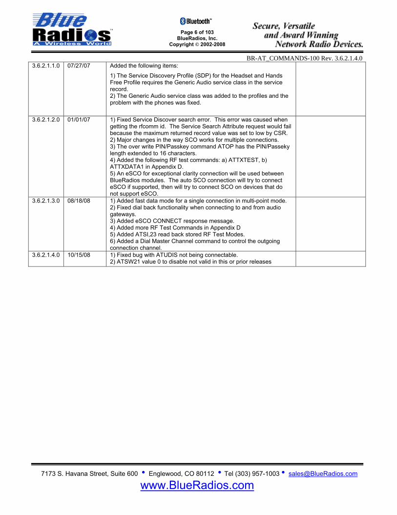
3.6.2.1.1.0 07/27/07 Added the following items:
1) The Service Discovery Profile (SDP) for the Headset and Hands Free Profile requires the Generic Audio service class in the service record. 2) The Generic Audio service class was added to the profiles and the problem with the phones was fixed.
3.6.2.1.2.0 01/01/07 1) Fixed Service Discover search error. This error was caused when getting the rfcomm id. The Service Search Attribute request would fail because the maximum returned record value was set to low by CSR. 2) Major changes in the way SCO works for multiple connections. 3) The over write PIN/Passkey command ATOP has the PIN/Passeky length extended to 16 characters. 4) Added the following RF test commands: a) ATTXTEST, b) ATTXDATA1 in Appendix D. 5) An eSCO for exceptional clarity connection will be used between BlueRadios modules. The auto SCO connection will try to connect eSCO if supported, then will try to connect SCO on devices that do not support eSCO.
3.6.2.1.3.0 08/18/08
1) Added fast data mode for a single connection in multi-point mode. 2) Fixed dial back functionality when connecting to and from audio gateways. 3) Added eSCO CONNECT response message. 4) Added more RF Test Commands in Appendix D 5) Added ATSI,23 read back stored RF Test Modes. 6) Added a Dial Master Channel command to control the outgoing connection channel.
3.6.2.1.4.0 10/15/08 1) Fixed bug with ATUDIS not being connectable. 2) ATSW21 value 0 to disable not valid in this or prior releases
Page 7 of 103
BlueRadios, Inc. Copyright © 2002-2008
BR-AT_COMMANDS-100 Rev. 3.6.2.1.4.0
7173 S. Havana Street, Suite 600 • Englewood, CO 80112 • Tel (303) 957-1003 • [email protected]
www.BlueRadios.com
IMPORTANT NOTES - PLEASE READ PRIOR TO CONTINUING
Audio is currently supported on Channel 0 only.
The Bluetooth radio’s reset logic is active LOW for C40 and C46 BC04 BTver2.0 modules.
Unlike the old firmware the new parser design will not accept line feed <lf> after issuing a valid AT
Command only a carriage return <cr> shall be used. To provide the best firmware architecture, design, and future profile support there is not 100%
code backwards compatibility in regards to certain AT Commands and responses. This release firmware is targeted to CSR BC04 platforms. The firmware was developed and tested on BC02 and BC04 platforms. The ATDI command response string no longer returns radio name. There is a separate command to request a remote device name based on CSR’s newest design implementation.
There is an error on Version F of the Eval Board. The two vias marked PIO6 and PIO7 are not
connected to their respective pins on the C40 module, only to the C46. If you need to take measurements from these pins you must measure directly from pins 3 and 4 of the radio. This will be corrected in the next version.
Overall performance improvements from BC02 to BC04:
Maximum data throughput for a single point-to-point connection in fast data mode Master to Slave is: 231.2kBps and Slave to Master is: 188.2kBps - While in regular data mode (AT Command parser running) it is only 35Kbps.
- Current consumption is 15% less.
- Inquiry responses are much faster.

Page 8 of 103
BlueRadios, Inc. Copyright © 2002-2008
BR-AT_COMMANDS-100 Rev. 3.6.2.1.4.0
7173 S. Havana Street, Suite 600 • Englewood, CO 80112 • Tel (303) 957-1003 • [email protected]
www.BlueRadios.com
Quick Start Guide for Evaluation Kit
First, install the CD ROM that came with the Bluetooth USB Communicator. This contains the BTW 5.1.0.1700 Bluetooth stack and GUI for Microsoft Windows platforms (98SE, 2000, ME, XP). If you already have Microsoft XP SP2 installed you can just plug in the USB device and Microsoft will recognize it and use its native Bluetooth stack interface software. During installation of the CD when the software prompts for the USB adapter, press 'Cancel'. After the computer reboots, insert the USB device. Let the Hardware installation wizard install the drivers. A window will pop up, select 'Express setup'.
Run: Programs -> Bluetooth -> Bluetooth Settings Add new connection. It will find and use a default name 'BlueRadios' after you have successfully powered up the BlueRadios Eval Board below:
Plug in the AC/DC wall transformer FIRST. Wait a second for the voltage to ramp up. Then plug the DC receptacle jack into the BlueRadios Eval Board, the red LED will light up. You will see a flashing green LED labeled PIO5. If the LED does not flash at ~1Hz, the power did not ramp up fast enough for the module to boot properly. You can simply press SW1 (black button) on the Eval Board to reset.
On the computer, press 'BlueRadios' icon for a connection. The blue LED PIO2 will light on the BlueRadios Eval Board.
Run HyperTerminal Private Edition 6.3 with factory default settings (do not echo characters or append any additional line feeds). Connect to COM40 at 9600 (8,N,1) baud rate settings, and using hardware flow control. The stack program uses virtual com ports assigned in the Bluetooth configuration window on the computer.
PC to PC RF loop-back test: You can simply connect the DB9 (RS-232) on the Eval Board directly to the same PC’s COM1 port using the RS-232 serial pass through cable supplied in the kit. A null modem is not required. Open another HyperTerminal session and use the same baud rate settings above. Embedded testing: For the DB9 (RS-232) connector, connect the TX(2), RX(3) and GND(5) to the embedded computer or micro controller. If you are not using hardware flow control, connect RTS(7) to CTS(8) on the DB-9 connector. When connecting the TX and RX from the DB9 connector, you cannot connect/short the CTS and RTS at terminal J4 these are two different circuits. Note: Most commercial devices ship from the factor with security enabled. If prompted for a PIN/Passkkey it is the lower case word “default” in BlueRadios modules. You can disable security on the PC Bluetooth software so you do not always have to enter this.

Page 9 of 103
BlueRadios, Inc. Copyright © 2002-2008
BR-AT_COMMANDS-100 Rev. 3.6.2.1.4.0
7173 S. Havana Street, Suite 600 • Englewood, CO 80112 • Tel (303) 957-1003 • [email protected]
www.BlueRadios.com
1 Introduction Scope: This ATMP (Multi-Point) Command Set document along with BlueRadios® evaluation board was created to enable developers and integrators an opportunity to evaluate wireless networks using Bluetooth technology. The goal is to make the transition to Bluetooth wireless networks as seamless and easy as possible for our clients. This document will explain how to establish Bluetooth communications between two or more BlueRadios for both data and voice applications in a point-to-point network (i.e., cable replacement, slave/master communications only). “Our technology delivers a dynamic experience that comes out of the wireless delivery mechanism and the freedom to connect others.”
Mark J. Kramer – CEO of BlueRadios
This document describes the hardware interface of BlueRadios Intelligent Serial Module. The Module is designed to be built into an embedded device and to provide a simple and low cost Bluetooth API interface. The module is designed to integrate with a wide range of applications and platforms with a simple electrical and software interface using AT commands. Background: The BlueRadios evaluation board is designed to accommodate the Companies Class1 or Class2 Bluetooth radio modem serial modules with 2.4GHz RF ceramic chip antenna (pictured right). The BlueRadios SMT modules are Bluetooth ver2.0 compliant and use the BC04 Base band processor from CSR. The evaluation board enables a stable platform environment to test serial RS-232 cable replacement and audio communications over Bluetooth RF links before going directly to an embedded printed circuit board design and layout. AT Commands: This document describes the protocol used to control and configure BlueRadios Bluetooth Serial Modules. The protocol is similar to the industry standard Hayes AT protocol used in telephone modems due to the fact that both types of devices are connection oriented. Appropriate AT commands have been provided to make the module perform the two core actions of a Bluetooth device, which is make/break connections and Inquiry. Additional AT commands are also provided to perform ancillary functions. The CSR (Cambridge Silicon Radio) BC04 base band processors are used in the BlueRadios modules. Memory resources are limited therefore it is NOT proposed that there be full implementation of the AT protocol similar to an AT modem. But in fact, the protocol is similar enough so the existing source code written for modems can be used with very little modifications with this serial module. Also because of the same resource limitations the Multi-Point modules support connections up to 4 remote devices. Just like telephone modems, the serial module powers up into an unconnected state and will respond to inquiry and connection requests. Then, just like controlling a modem, the host or client can issue AT commands which map to various Bluetooth activities. The command set is extensive enough to allow a host to make connections which are authenticated and encrypted or not. The BlueRadios serial radio modems can be configured, commanded, and controlled through simple ASCII strings through the hardware serial UART or over a remote Bluetooth RF connection.
1. All commands have the following format: “command”<cr>. Where “cr” represents carriage return 0x0D 2. Valid commands respond with a “<cr,lf>OK<cr,lf> or “<cr,lf>ERROR<cr,lf>. Where “lf” represents linefeed
0x0A. The Only exceptions are ATSW20 and ATURST which do not reply (setting baud rate and CPU reset.
3. All response data after the command response have the following format <cr,lf>data<cr,lf>. HEX vs. Decimal – When writing or entering integer AT Command string values these are typically in Decimal format, when reading values from memory they are returned in HEX (hexadecimal).
Page 10 of 103
BlueRadios, Inc. Copyright © 2002-2008
BR-AT_COMMANDS-100 Rev. 3.6.2.1.4.0
7173 S. Havana Street, Suite 600 • Englewood, CO 80112 • Tel (303) 957-1003 • [email protected]
www.BlueRadios.com
Applications: The BlueRadios evaluation board can be used for both embedded and PC product applications. It has a RS-232 DB-9 and J4 (0-3.3Vdc) direct UART interfaces to the module. There are radio modem input/output pins (PIO’s) connected to terminal lugs for applications that require external command and control. The design incorporates a 13bit mono audio codec, jack, and MIC volume control for wireless headset applications over SCO channel. The audio circuit has minimum filtering for noise, etc. Pico-Nets: For applications that require more than point-to-point (2) devices communicating simultaneously – this is called a pico-net. These applications require one of the Bluetooth devices to manage all the network connections. Because of hardware restrictions, the BlueRadios module supports up to 4 remote slave/master connections and each channel connection status is output to a dedicated PIO pin. Note: AT Command interface protocol is not used for the USB Bluetooth communicator. The stack for this resides on the PC side not embedded in the unit like the serial SMT BlueRadios modules. Making a Connection
Serial Interface UART_TX, UART_RX, UART_RTS and UART_CTS form a conventional asynchronous serial data port. The interface is designed to operate correctly when connected to other UART devices such as the 16550A. The signaling levels are nominal 0V and 3.3V and are inverted with respect to the signaling on an RS232 cable. The interface is programmable. The default condition on power-up is pre-assigned in the external 8Mb Flash. Two-way hardware flow control is implemented by UART_RTS and UART_CTS. UART_RTS is an output and is active low. UART_CTS is an input and is active low. These signals operate according to normal industry convention. BlueRadios shows up under Service discovery defaulted as Serial Port Profile (SPP) Service “COM0, COM1, COM2, and COM3 on BlueRadios”, where COMX is the arbitrary service name and BlueRadios is the local device name. All of these name settings are configurable by the user. To connect to BlueRadios, browse for services, you should see: “BlueRadios “Serial Port” as the Profile. BlueRadios uses SPP as default, and will be connected to a Virtual COM port on PCs, Palm Pilot’s, PocketPCs, or other clients. Once connected, the Bluetooth address for each device is exchanged with the message CONNECT, displayed, and data will flow in both directions in regular data mode as if the serial port were locally attached. AT commands can be sent directly to the radios UART when not Bluetooth connected or by any remote Bluetooth RF device connection after typing +++ followed by a carriage return. The +++ is the factory default escape sequence to place the radio in command mode when there is a Bluetooth RF connection. The Slave radios UART will respond automatically with DISCONNECT in point-to-point mode or DISCONNECT,00 in multi-point mode when it is disconnected from Channel 00 for example. This verbalization response can be changed to short/long or none if preferred using ATSW24 power up default settings. BlueRadios Class1 Bluetooth device with a high power transceiver (100meters/330 feet) or (10 meters/33 feet) for Class2 performance, however; actual range may vary due to environment, type of antenna, board layout, enclosure design or type of client device used to connect to BlueRadios. We have an AT Command to control and set the maximum RF output power. Note: Only one device can make connection to BlueRadios at a time, and there is a limit of 8 simultaneous communicating devices in a Bluetooth pico-net network. BlueRadios Evaluation Board Physical Ports (3rd Generation)
Page 11 of 103
BlueRadios, Inc. Copyright © 2002-2008
BR-AT_COMMANDS-100 Rev. 3.6.2.1.4.0
7173 S. Havana Street, Suite 600 • Englewood, CO 80112 • Tel (303) 957-1003 • [email protected]
www.BlueRadios.com
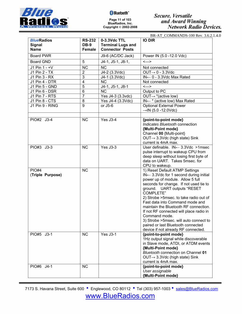
BlueRadios Signal Name
RS-232 DB-9 Female
0-3.3Vdc TTL Terminal Lugs and Connector Posts
IO DIR
Board PWR J9-6 (AC/DC Jack) Power IN (5.0 -12.0 Vdc) Board GND 5 J4-1, J5-1, J8-1, <—> J1 Pin 1 - +V NC NC Not connected J1 Pin 2 - TX 2 J4-2 (3.3Vdc) OUT→ 0 - 3.3Vdc J1 Pin 3 - RX 3 J4-1 (3.3Vdc) IN← 0 - 3.3Vdc Max Rated J1 Pin 4 - DTR 4 NC Not connected J1 Pin 5 - GND 5 J4-1, J5-1, J8-1 <—> J1 Pin 6 - DSR 6 NC Output to PC J1 Pin 7 - RTS 7 Yes J4-3 (3.3vdc) OUT→ *(active low) J1 Pin 8 - CTS 8 Yes J4-4 (3.3Vdc) IN← * (active low) Max Rated J1 Pin 9 - RING 9 or J5-6 Optional External Power
→IN (5.0 -12.0Vdc) PIO#2 J3-4 NC Yes J3-4 point-to-point mode
Indicates Bluetooth connection Multi-Point mode Channel 00 Multi-point OUT→ 3.3Vdc (high state) Sink current is 4mA max.
PIO#3 J3-3 NC Yes J3-3 User definable. IN← 3.3Vdc >1msec pulse interrupt to wakeup CPU from deep sleep without losing first byte of data on UART. Takes 5msec. for CPU to wakeup.
PIO#4 (Triple Purpose)
NC 1) Reset Default ATMP Settings IN← 3.3Vdc for 1 second during initial power up of module. Allow 5 full seconds for change. If not used tie to ground. UART outputs “RESET COMPLETE” 2) Strobe >5msec. to take radio out of Fast data into Command mode and maintain the Bluetooth RF connection. If not RF connected will place radio in Command mode. 3) Strobe >5msec. will auto connect to paired or last Bluetooth connected device if not already RF connected.
PIO#5 J3-1 NC Yes J3-1 point-to-point mode 1Hz output signal while discoverable in Slave mode, ATDI, or ATDM events Multi-Point mode Bluetooth connection on Channel 01 OUT→ 3.3Vdc (high state) Sink current is 4mA max.
PIO#6 J4-1 NC point-to-point mode User assignable Multi-Point mode
Page 12 of 103
BlueRadios, Inc. Copyright © 2002-2008
BR-AT_COMMANDS-100 Rev. 3.6.2.1.4.0
7173 S. Havana Street, Suite 600 • Englewood, CO 80112 • Tel (303) 957-1003 • [email protected]
www.BlueRadios.com
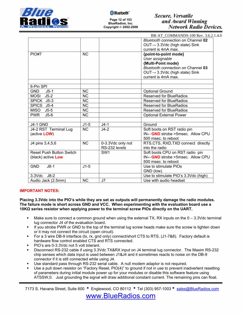
Bluetooth connection on Channel 02 OUT→ 3.3Vdc (high state) Sink current is 4mA max.
PIO#7 NC point-to-point mode User assignable Multi-Point mode Bluetooth connection on Channel 03 OUT→ 3.3Vdc (high state) Sink current is 4mA max.
6-Pin SPI GND J5-1 NC Optional Ground MOSI J5-2 NC Reserved for BlueRadios SPICK J5-3 NC Reserved for BlueRadios SPICS J5-4 NC Reserved for BlueRadios MISO J5-5 NC Reserved for BlueRadios PWR J5-6 NC Optional External Power J4-1 GND J1-5 J4-1 Ground J4-2 RST Terminal Lug (active LOW)
NC J4-2 Soft boots on RST radio pin IN←GND strobe >5msec. Allow CPU 500 msec. to reboot
J4 pins 3,4,5,6 NC 0-3.3Vdc only not RS-232 levels
RTS,CTS, RXD,TXD connect directly into the radio
Reset Push Button Switch (black) active Low
SW1 Soft boots CPU on RST radio pin IN←GND strobe >5msec. Allow CPU 500 msec. to reboot
GND J8-1 J1-5 Use to stimulate PIOs GND (low)
3.3Vdc J8-2 Use to stimulate PIO’s 3.3Vdc (high) Audio Jack (2.5mm) NC J7 Use with audio headset
IMPORTANT NOTES: Placing 3.3Vdc into the PIO’s while they are set as outputs will permanently damage the radio modules. The failure mode is short across GND and VCC. When experimenting with the evaluation board use a 10KΩ series resistor when applying power to the terminal screw PIOs directly on the UART.
Make sure to connect a common ground when using the external TX, RX inputs on the 0 – 3.3Vdc terminal lug connector J4 of the evaluation board.
If you strobe PWR or GND to the top of the terminal lug screw heads make sure the screw is tighten down or it may not connect the circuit (open circuit).
For a 3 wire DB-9 interface (tx, rx, gnd only) connect/short CTS to RTS, (J1-7&8). Factory default is hardware flow control enabled CTS and RTS connected.
PIO’s are 0-3.3Vdc not 5 volt tolerant. Disconnect RS-232 cable if using 3.3Vdc TX&RX input on J4 terminal lug connector. The Maxim RS-232
chip senses which data input is used between J1&J4 and it sometimes reacts to noise on the DB-9 connector if it is still connected while using J4.
Use standard pass through RS-232 serial cable. A null modem adaptor is not required. Use a pull down resistor on “Factory Reset, PIO(4)” to ground if not in use to prevent inadvertent resetting
of parameters during initial module power up for your modules or disable this software feature using ATSSW,0. Just grounding the signal will draw additional constant current. The remaining pins can float.
Page 13 of 103
BlueRadios, Inc. Copyright © 2002-2008
BR-AT_COMMANDS-100 Rev. 3.6.2.1.4.0
7173 S. Havana Street, Suite 600 • Englewood, CO 80112 • Tel (303) 957-1003 • [email protected]
www.BlueRadios.com
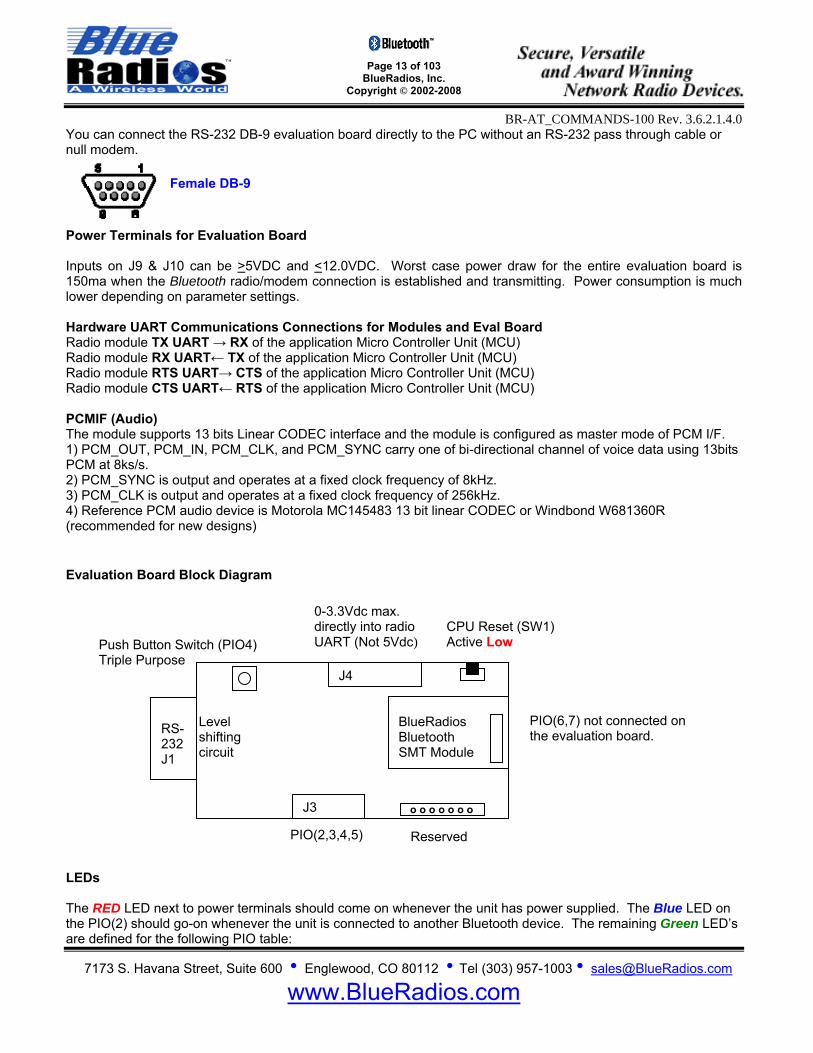
You can connect the RS-232 DB-9 evaluation board directly to the PC without an RS-232 pass through cable or null modem.
Female DB-9
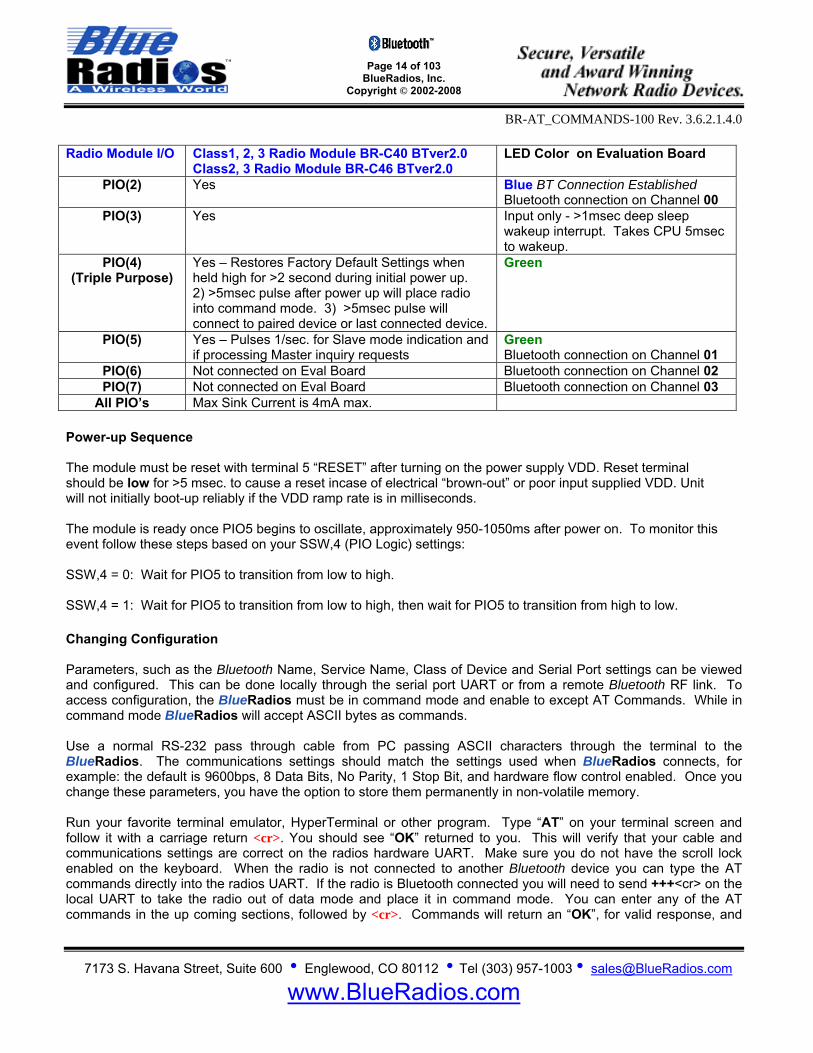
Power Terminals for Evaluation Board Inputs on J9 & J10 can be >5VDC and <12.0VDC. Worst case power draw for the entire evaluation board is 150ma when the Bluetooth radio/modem connection is established and transmitting. Power consumption is much lower depending on parameter settings. Hardware UART Communications Connections for Modules and Eval Board Radio module TX UART → RX of the application Micro Controller Unit (MCU) Radio module RX UART← TX of the application Micro Controller Unit (MCU) Radio module RTS UART→ CTS of the application Micro Controller Unit (MCU) Radio module CTS UART← RTS of the application Micro Controller Unit (MCU) PCMIF (Audio) The module supports 13 bits Linear CODEC interface and the module is configured as master mode of PCM I/F. 1) PCM_OUT, PCM_IN, PCM_CLK, and PCM_SYNC carry one of bi-directional channel of voice data using 13bits PCM at 8ks/s. 2) PCM_SYNC is output and operates at a fixed clock frequency of 8kHz. 3) PCM_CLK is output and operates at a fixed clock frequency of 256kHz. 4) Reference PCM audio device is Motorola MC145483 13 bit linear CODEC or Windbond W681360R (recommended for new designs) Evaluation Board Block Diagram LEDs The RED LED next to power terminals should come on whenever the unit has power supplied. The Blue LED on the PIO(2) should go-on whenever the unit is connected to another Bluetooth device. The remaining Green LED’s are defined for the following PIO table:
Push Button Switch (PIO4) Triple Purpose
RS-232 J1
J4
J3
BlueRadios Bluetooth SMT Module
0-3.3Vdc max. directly into radio UART (Not 5Vdc)
Level shifting circuit
CPU Reset (SW1) Active Low
PIO(2,3,4,5)
o o o o o o o
PIO(6,7) not connected on the evaluation board.
Reserved
Page 14 of 103
BlueRadios, Inc. Copyright © 2002-2008
BR-AT_COMMANDS-100 Rev. 3.6.2.1.4.0
7173 S. Havana Street, Suite 600 • Englewood, CO 80112 • Tel (303) 957-1003 • [email protected]
www.BlueRadios.com
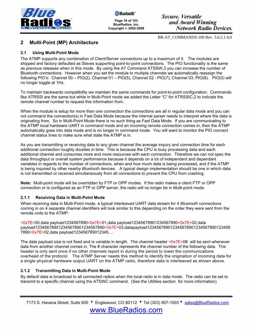
Radio Module I/O Class1, 2, 3 Radio Module BR-C40 BTver2.0
Class2, 3 Radio Module BR-C46 BTver2.0 LED Color on Evaluation Board
PIO(2) Yes Blue BT Connection Established Bluetooth connection on Channel 00
PIO(3) Yes Input only - >1msec deep sleep wakeup interrupt. Takes CPU 5msec to wakeup.
PIO(4) (Triple Purpose)
Yes – Restores Factory Default Settings when held high for >2 second during initial power up. 2) >5msec pulse after power up will place radio into command mode. 3) >5msec pulse will connect to paired device or last connected device.
Green
PIO(5)
Yes – Pulses 1/sec. for Slave mode indication and if processing Master inquiry requests
Green Bluetooth connection on Channel 01
PIO(6) Not connected on Eval Board Bluetooth connection on Channel 02 PIO(7) Not connected on Eval Board Bluetooth connection on Channel 03
All PIO’s Max Sink Current is 4mA max. Power-up Sequence The module must be reset with terminal 5 “RESET” after turning on the power supply VDD. Reset terminal should be low for >5 msec. to cause a reset incase of electrical “brown-out” or poor input supplied VDD. Unit will not initially boot-up reliably if the VDD ramp rate is in milliseconds. The module is ready once PIO5 begins to oscillate, approximately 950-1050ms after power on. To monitor this event follow these steps based on your SSW,4 (PIO Logic) settings: SSW,4 = 0: Wait for PIO5 to transition from low to high. SSW,4 = 1: Wait for PIO5 to transition from low to high, then wait for PIO5 to transition from high to low. Changing Configuration Parameters, such as the Bluetooth Name, Service Name, Class of Device and Serial Port settings can be viewed and configured. This can be done locally through the serial port UART or from a remote Bluetooth RF link. To access configuration, the BlueRadios must be in command mode and enable to except AT Commands. While in command mode BlueRadios will accept ASCII bytes as commands. Use a normal RS-232 pass through cable from PC passing ASCII characters through the terminal to the BlueRadios. The communications settings should match the settings used when BlueRadios connects, for example: the default is 9600bps, 8 Data Bits, No Parity, 1 Stop Bit, and hardware flow control enabled. Once you change these parameters, you have the option to store them permanently in non-volatile memory. Run your favorite terminal emulator, HyperTerminal or other program. Type “AT” on your terminal screen and follow it with a carriage return <cr>. You should see “OK” returned to you. This will verify that your cable and communications settings are correct on the radios hardware UART. Make sure you do not have the scroll lock enabled on the keyboard. When the radio is not connected to another Bluetooth device you can type the AT commands directly into the radios UART. If the radio is Bluetooth connected you will need to send +++<cr> on the local UART to take the radio out of data mode and place it in command mode. You can enter any of the AT commands in the up coming sections, followed by <cr>. Commands will return an “OK”, for valid response, and
Page 15 of 103
BlueRadios, Inc. Copyright © 2002-2008
BR-AT_COMMANDS-100 Rev. 3.6.2.1.4.0
7173 S. Havana Street, Suite 600 • Englewood, CO 80112 • Tel (303) 957-1003 • [email protected]
www.BlueRadios.com
invalid ones will reply ERROR. To go back to regular data mode while RF connected type ATMD to pass or receive data from a remote connected Bluetooth device. Note: If changing communications parameter settings, remember to change your terminal or emulator comm. settings to correspond to the new parameter settings you just have made. Also, we have seen some strange communications effects using HyperTerminal in conjunction with a PC using various Bluetooth stack and virtual com ports. As an example; communications works only in one direction. Requires closing both HyperTerminal programs and starting both HyperTerminal sessions again.
Page 16 of 103
BlueRadios, Inc. Copyright © 2002-2008
BR-AT_COMMANDS-100 Rev. 3.6.2.1.4.0
7173 S. Havana Street, Suite 600 • Englewood, CO 80112 • Tel (303) 957-1003 • [email protected]
www.BlueRadios.com
2 Multi-Point (MP) Architecture
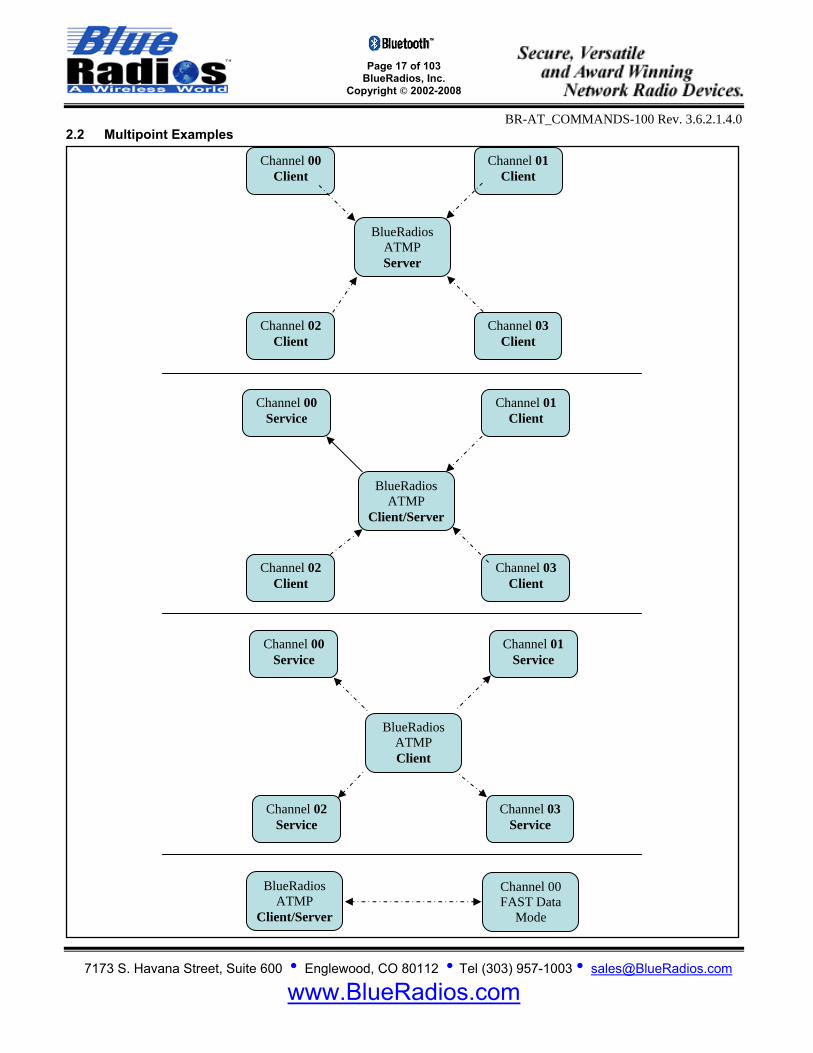
2.1 Using Multi-Point Mode The ATMP supports any combination of Client/Server connections up to a maximum of 4. The modules are shipped and factory defaulted as Slaves supporting point-to-point connections. The PIO functionality is the same as previous releases when in this mode. By using the AT Command ATSSW,3 you can increase the number of Bluetooth connections. However when you set the module to multiple channels we automatically reassign the following PIO’s: Channel 00 – PIO(2), Channel 01 – PIO(5), Channel 02 - PIO(7), Channel 03, PIO(8). PIO(5) will no longer toggle at 1Hz. To maintain backwards compatibility we maintain the same commands for point-to-point configuration. Commands like ATRSSI are the same but while in Multi-Point mode we added the Letter “C” for ATRSSIC,2 to indicate the remote channel number to request this information from. When the module is setup for more than one connection the connections are all in regular data mode and you can not command the connection(s) in Fast Data Mode because the internal parser needs to interpret where the data is originating from. So in Multi-Point Mode there is no such thing as Fast Data Mode. If you are communicating to the ATMP local hardware UART in command mode and an incoming remote connection comes in, then the ATMP automatically goes into data mode and is no longer in command mode. You will want to monitor the PIO connect channel status lines to make sure what state the ATMP is in. As you are transmitting or receiving data to any given channel the average inquiry and connection time for each additional connection roughly doubles in time. This is because the CPU is busy processing data and each additional channel and consumes more and more resources with each connection. Therefore we can not spec the data throughput or overall system performance because it depends on a lot of independent and dependant variables in regards to the number of connections, when and how much data is being processed, and if the ATMP is being inquired by other nearby Bluetooth devices. A typical design implementation should be one in which data is not transmitted or received simultaneously from all connections to prevent the CPU from crashing. Note: Multi-point mode will be overridden by FTP or OPP modes. If the radio makes a client FTP or OPP connection or is configured as an FTP or OPP server, the radio will no longer be in Multi-point mode.
2.1.1 Receiving Data in Multi-Point Mode When receiving data in Multi-Point mode, a typical interleaved UART data stream for 4 Bluetooth connections coming in on 4 separate channel identifiers will look similar to this depending on the order they were sent from the remote units to the ATMP: <0x7E>00,data payload1234567890<0x7E>01,data payload12345678901234567890<0x7E>02,data payload123456789012345678901234567890<0x7E>03,datapayload1234567890123456789012345678901234567890<0x7E>02,data payload123456789012345…. The data payload size is not fixed and is variable in length. The channel header <0x7E>0#, will be sent whenever data from another channel comes in. The # character represents the channel number of the following data. The header is only sent once if no other channels report in during the period to lower the communications overhead of the protocol. The ATMP Server needs this method to identify the origination of incoming data for a single physical hardware output UART on the ATMP radio, therefore data is interleaved as shown above.
2.1.2 Transmitting Data in Multi-Point Mode By default data is broadcast to all connected radios when the local radio is in data mode. The radio can be set to transmit to a specific channel using the ATSWC command. (See the Utilities section for more information)
Page 17 of 103
BlueRadios, Inc. Copyright © 2002-2008
BR-AT_COMMANDS-100 Rev. 3.6.2.1.4.0
7173 S. Havana Street, Suite 600 • Englewood, CO 80112 • Tel (303) 957-1003 • [email protected]
www.BlueRadios.com
2.2 Multipoint Examples
BlueRadios ATMP Server
Channel 00 Client
Channel 01 Client
Channel 02 Client
Channel 03 Client
Channel 00 Service
Channel 01 Client
Channel 02 Client
Channel 03 Client
BlueRadios ATMP
Client/Server
Channel 00 Service
Channel 01 Service
BlueRadios ATMP Client
Channel 02 Service
Channel 03 Service
BlueRadios ATMP
Client/Server
Channel 00 FAST Data
Mode
Page 18 of 103
BlueRadios, Inc. Copyright © 2002-2008
BR-AT_COMMANDS-100 Rev. 3.6.2.1.4.0
7173 S. Havana Street, Suite 600 • Englewood, CO 80112 • Tel (303) 957-1003 • [email protected]
www.BlueRadios.com
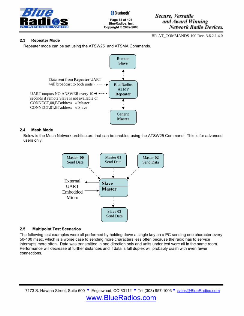
2.3 Repeater Mode Repeater mode can be set using the ATSW25 and ATSMA Commands.
2.4 Mesh Mode Below is the Mesh Network architecture that can be enabled using the ATSW25 Command. This is for advanced users only.
2.5 Multipoint Test Scenarios The following test examples were all performed by holding down a single key on a PC sending one character every 50-100 msec, which is a worse case to sending more characters less often because the radio has to service interrupts more often. Data was transmitted in one direction only and units under test were all in the same room. Performance will decrease at further distances and if data is full duplex will probably crash with even fewer connections.
Remote Slave
BlueRadios ATMP
Repeater
Generic Master
Data sent from Repeater UART will broadcast to both units
UART outputs NO ANSWER every 10 seconds if remote Slave is not available or CONNECT,00,BTaddress // Master CONNECT,01,BTaddress // Slave
Slave Master
Master 02 Send Data
Master 00 Send Data
Master 01 Send Data
Slave 03 Send Data
External UART
Embedded Micro
Page 19 of 103
BlueRadios, Inc. Copyright © 2002-2008
BR-AT_COMMANDS-100 Rev. 3.6.2.1.4.0
7173 S. Havana Street, Suite 600 • Englewood, CO 80112 • Tel (303) 957-1003 • [email protected]
www.BlueRadios.com
Slave
Master 00 Send Data
Master 02 Send Data
Master 01 Send Data
Master 03 Send Data
Data Out
UART
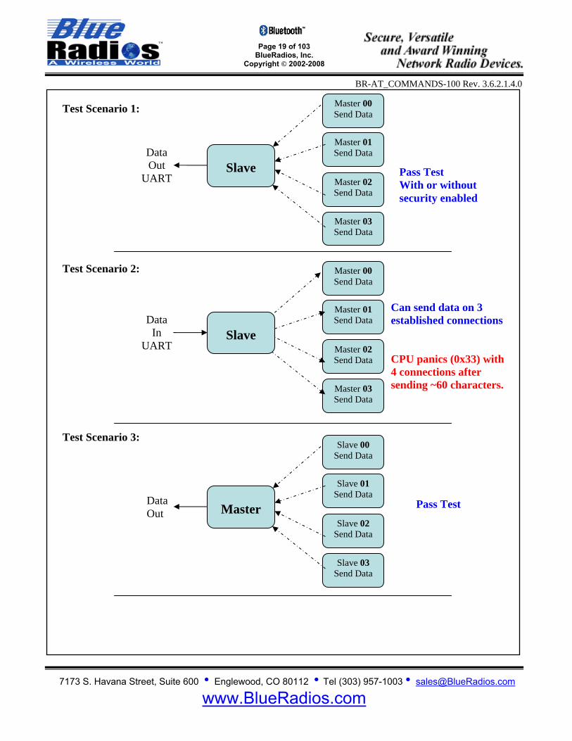
Pass Test With or without security enabled
Master
Slave 00 Send Data
Slave 02 Send Data
Slave 01 Send Data
Slave 03 Send Data
Data Out
Pass Test
Slave
Master 00 Send Data
Master 02 Send Data
Master 01 Send Data
Master 03 Send Data
Data In
UART
Can send data on 3 established connections CPU panics (0x33) with 4 connections after sending ~60 characters.
Test Scenario 1:
Test Scenario 2:
Test Scenario 3:

Page 20 of 103
BlueRadios, Inc. Copyright © 2002-2008
BR-AT_COMMANDS-100 Rev. 3.6.2.1.4.0
7173 S. Havana Street, Suite 600 • Englewood, CO 80112 • Tel (303) 957-1003 • [email protected]
www.BlueRadios.com
Master & Slave
Master 00 Send Data
Slave 02 Send Data
Master 01 Send Data
Slave 03 Send Data
Data Out
UART
Pass Test
Master
Slave 00 RX Data
Slave 02 RX Data
Slave 01 RX Data
Slave 03 RX Data
Data In
UART
Pass Test for 3 connections With 4 connections CPU panics (0x33) after ~60 characters
Master & Slave
Master 00 RX Data
Slave 02 RX Data
Master 01 RX Data
Slave 03 RX Data
Data In
UART
Can send data on 3 established connections Unit crashes on 4 connections after sending ~60 characters
Test Scenario 4:
Test Scenario 5:
Test Scenario 6:
Page 21 of 103
BlueRadios, Inc. Copyright © 2002-2008
BR-AT_COMMANDS-100 Rev. 3.6.2.1.4.0
7173 S. Havana Street, Suite 600 • Englewood, CO 80112 • Tel (303) 957-1003 • [email protected]
www.BlueRadios.com
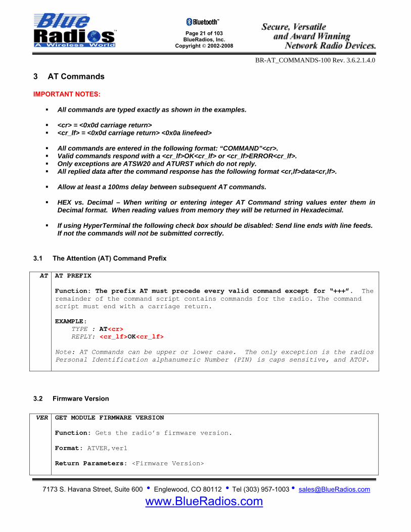
3 AT Commands IMPORTANT NOTES:
All commands are typed exactly as shown in the examples.
<cr> = <0x0d carriage return> <cr_lf> = <0x0d carriage return> <0x0a linefeed>
All commands are entered in the following format: “COMMAND”<cr>. Valid commands respond with a <cr_lf>OK<cr_lf> or <cr_lf>ERROR<cr_lf>. Only exceptions are ATSW20 and ATURST which do not reply. All replied data after the command response has the following format <cr,lf>data<cr,lf>.
Allow at least a 100ms delay between subsequent AT commands.
HEX vs. Decimal – When writing or entering integer AT Command string values enter them in
Decimal format. When reading values from memory they will be returned in Hexadecimal.
If using HyperTerminal the following check box should be disabled: Send line ends with line feeds. If not the commands will not be submitted correctly.
3.1 The Attention (AT) Command Prefix AT AT PREFIX
Function: The prefix AT must precede every valid command except for “+++”. The remainder of the command script contains commands for the radio. The command script must end with a carriage return. EXAMPLE: TYPE : AT<cr> REPLY: <cr_lf>OK<cr_lf> Note: AT Commands can be upper or lower case. The only exception is the radios Personal Identification alphanumeric Number (PIN) is caps sensitive, and ATOP.
3.2 Firmware Version VER GET MODULE FIRMWARE VERSION
Function: Gets the radio’s firmware version. Format: ATVER,ver1 Return Parameters: <Firmware Version>
Page 22 of 103
BlueRadios, Inc. Copyright © 2002-2008
BR-AT_COMMANDS-100 Rev. 3.6.2.1.4.0
7173 S. Havana Street, Suite 600 • Englewood, CO 80112 • Tel (303) 957-1003 • [email protected]
www.BlueRadios.com
EXAMPLE: TYPE : ATVER,ver1<cr> REPLY: <cr_lf>OK<cr_lf>
<cr_lf>Ver 3.6.2.1.4.0<cr_lf> Notes:
“ver1” is case sensitive, be sure to enter it in lower case.
Make sure the radios’s version number matches this document version before proceeding.
3.3 Resetting the Radio URST RESET
Function: Tells the radio to perform software reset on the CPU. Format: ATURST EXAMPLE: TYPE : ATURST<cr> REPLY: None Notes:
This unique Command does not reply with “OK” or “ERROR” because of internal UART data processing limitations and response timing.
You can send the reset command through the UART or over the Bluetooth
RF connection.
The BlueRadios evaluation board has a convenient manual pushbutton software reset switch on the PCB labeled SW1.
FRST FACTORY RESET
Function: Resets the radio back to factory defaults. Format: ATFRST EXAMPLE: TYPE : ATFRST<cr> REPLY: <cr_lf>OK<cr_lf> <cr_lf>RESET COMPLETE<cr_lf> OR <cr_lf>ERROR<cr_lf> Notes:
You can send the factory reset command through the UART or over the Bluetooth RF connection.
Page 23 of 103
BlueRadios, Inc. Copyright © 2002-2008
BR-AT_COMMANDS-100 Rev. 3.6.2.1.4.0
7173 S. Havana Street, Suite 600 • Englewood, CO 80112 • Tel (303) 957-1003 • [email protected]
www.BlueRadios.com
The BlueRadios evaluation board has a convenient manual pushbutton factory reset switch on the PCB labeled PIO(4). It resets the radio back to factory defaults if the button is held down while power is applied to the radio. Allow 2 seconds for the Radio to read and write to FLASH.
SSW,0 SET BYPASS FOR HARDWARE FACTORY CONFIGURATION RESET PIO(4)
Function: Use this command in replace of physically connecting PIO(4) to ground to prevent an inadvertent factory configuration reset. Format: ATSSW,0,<Enable/Disable> Parameters:
Enable/Disable: 0 = PIO(4) factory reset enabled 1 = PIO(4) factory reset disabled
EXAMPLE: TYPE : ATSSW,0,1<cr> REPLY: <cr_lf>OK<cr_lf> OR <cr_lf>ERROR<cr_lf> Read Using: ATRSW,0
RSW,0 READ BYPASS FOR HARDWARE FACTORY CONFIGURATION RESET PIO(4) Function: Reads the PIO(4) factory reset enable/disable register state. Format: ATRSW,0 Return Parameters: <Enable/Disable> EXAMPLE: TYPE : ATRSW,0<cr> REPLY: <cr_lf>OK<cr_lf> <cr_lf>00<cr_lf> Set Using: ATSSW,0
3.4 Set/Get Radio Information
3.4.1 Get Status Information Status Information can be obtained directly from the Bluetooth Radio. This information is important when managing a connection list of devices in a local area and current settings of the radio. SI STATUS INFORMATION
Function: Gets specified status information from the LOCAL radio.
Page 24 of 103
BlueRadios, Inc. Copyright © 2002-2008
BR-AT_COMMANDS-100 Rev. 3.6.2.1.4.0
7173 S. Havana Street, Suite 600 • Englewood, CO 80112 • Tel (303) 957-1003 • [email protected]
www.BlueRadios.com
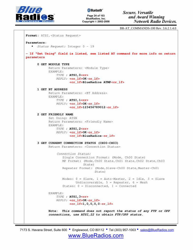
Format: ATSI,<Status Request> Parameters:
Status Request: Integer 0 – 19 - If “Set Using” field is listed, see listed AT command for more info on return parameters
0 GET MODULE TYPE Return Parameters: <Module Type> EXAMPLE:
TYPE : ATSI,0<cr> REPLY: <cr_lf>OK<cr_lf> <cr_lf>BlueRadios ATMP<cr_lf>
1 GET BT ADDRESS
Return Parameters: <BT Address> EXAMPLE:
TYPE : ATSI,1<cr> REPLY: <cr_lf>OK<cr_lf> <cr_lf>123456789012<cr_lf>
2 GET FRIENDLY NAME
Set Using: ATSN Return Parameters: <Friendly Name> EXAMPLE:
TYPE : ATSI,2<cr> REPLY: <cr_lf>OK<cr_lf> <cr_lf>BlueRadios<cr_lf>
3 GET CURRENT CONNECTION STATUS (CH00-CH03) Return Parameters: <Connection Status>
Connection Status: Single Connection Format: (Mode, Ch00 State) MP Format: (Mode,Ch00 State,Ch01 State,Ch02 State,Ch03 State) Repeater Format: (Mode,Slave-Ch00 State,Master-Ch01 State)
Modes: 0 = Slave, 1 = Auto-Master, 2 = Idle, 3 = Slave Undiscoverable, 5 = Repeater, 6 = Mesh States: 0 = Disconnected, 1 = Connected
EXAMPLE: TYPE : ATSI,3<cr>
REPLY: <cr_lf>OK<cr_lf> <cr_lf>1,0,0,0,0<cr_lf> Note: This command does not report the status of any FTP or OPP connections, use ATSI,22 to obtain FTP/OPP status.
Page 25 of 103
BlueRadios, Inc. Copyright © 2002-2008
BR-AT_COMMANDS-100 Rev. 3.6.2.1.4.0
7173 S. Havana Street, Suite 600 • Englewood, CO 80112 • Tel (303) 957-1003 • [email protected]
www.BlueRadios.com
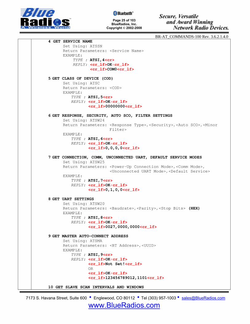
4 GET SERVICE NAME Set Using: ATSSN Return Parameters: <Service Name> EXAMPLE:
TYPE : ATSI,4<cr> REPLY: <cr_lf>OK<cr_lf> <cr_lf>COM0<cr_lf>
5 GET CLASS OF DEVICE (COD)
Set Using: ATSC Return Parameters: <COD> EXAMPLE:
TYPE : ATSI,5<cr> REPLY: <cr_lf>OK<cr_lf> <cr_lf>00000000<cr_lf>
6 GET RESPONSE, SECURITY, AUTO SCO, FILTER SETTINGS
Set Using: ATSW24 Return Parameters: <Response Type>,<Security>,<Auto SCO>,<Minor Filter> EXAMPLE:
TYPE : ATSI,6<cr> REPLY: <cr_lf>OK<cr_lf> <cr_lf>0,0,0,0<cr_lf>
7 GET CONNECTION, COMM, UNCONNECTED UART, DEFAULT SERVICE MODES
Set Using: ATSW25 Return Parameters: <Power-Up Connection Mode>,<Comm Mode>, <Unconnected UART Mode>,<Default Service> EXAMPLE:
TYPE : ATSI,7<cr> REPLY: <cr_lf>OK<cr_lf> <cr_lf>0,1,0,0<cr_lf>
8 GET UART SETTINGS
Set Using: ATSW20 Return Parameters: <Baudrate>,<Parity>,<Stop Bits> (HEX) EXAMPLE:
TYPE : ATSI,8<cr> REPLY: <cr_lf>OK<cr_lf> <cr_lf>0027,0000,0000<cr_lf>
9 GET MASTER AUTO-CONNECT ADDRESS
Set Using: ATSMA Return Parameters: <BT Address>,<UUID> EXAMPLE:
TYPE : ATSI,9<cr> REPLY: <cr_lf>OK<cr_lf> <cr_lf>Not Set!<cr_lf> OR <cr_lf>OK<cr_lf> <cr_lf>123456789012,1101<cr_lf>
10 GET SLAVE SCAN INTERVALS AND WINDOWS
Page 26 of 103
BlueRadios, Inc. Copyright © 2002-2008
BR-AT_COMMANDS-100 Rev. 3.6.2.1.4.0
7173 S. Havana Street, Suite 600 • Englewood, CO 80112 • Tel (303) 957-1003 • [email protected]
www.BlueRadios.com
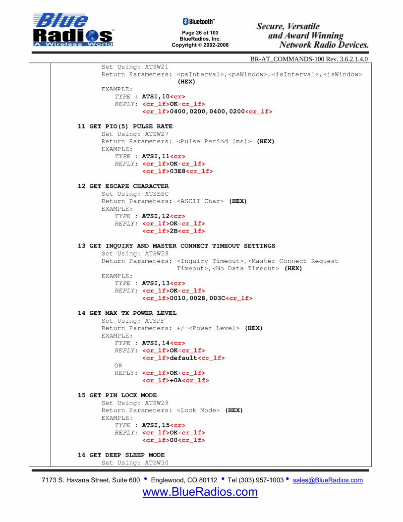
Set Using: ATSW21 Return Parameters: <psInterval>,<psWindow>,<isInterval>,<isWindow> (HEX) EXAMPLE:
TYPE : ATSI,10<cr> REPLY: <cr_lf>OK<cr_lf> <cr_lf>0400,0200,0400,0200<cr_lf>
11 GET PIO(5) PULSE RATE
Set Using: ATSW27 Return Parameters: <Pulse Period [ms]> (HEX) EXAMPLE:
TYPE : ATSI,11<cr> REPLY: <cr_lf>OK<cr_lf> <cr_lf>03E8<cr_lf>
12 GET ESCAPE CHARACTER Set Using: ATSESC Return Parameters: <ASCII Char> (HEX) EXAMPLE:
TYPE : ATSI,12<cr> REPLY: <cr_lf>OK<cr_lf> <cr_lf>2B<cr_lf>
13 GET INQUIRY AND MASTER CONNECT TIMEOUT SETTINGS
Set Using: ATSW28 Return Parameters: <Inquiry Timeout>,<Master Connect Request Timeout>,<No Data Timeout> (HEX) EXAMPLE:
TYPE : ATSI,13<cr> REPLY: <cr_lf>OK<cr_lf> <cr_lf>0010,0028,003C<cr_lf>
14 GET MAX TX POWER LEVEL Set Using: ATSPF Return Parameters: +/-<Power Level> (HEX) EXAMPLE:
TYPE : ATSI,14<cr> REPLY: <cr_lf>OK<cr_lf> <cr_lf>default<cr_lf> OR REPLY: <cr_lf>OK<cr_lf> <cr_lf>+0A<cr_lf>
15 GET PIN LOCK MODE
Set Using: ATSW29 Return Parameters: <Lock Mode> (HEX) EXAMPLE:
TYPE : ATSI,15<cr> REPLY: <cr_lf>OK<cr_lf> <cr_lf>00<cr_lf>
16 GET DEEP SLEEP MODE
Set Using: ATSW30
Page 27 of 103
BlueRadios, Inc. Copyright © 2002-2008
BR-AT_COMMANDS-100 Rev. 3.6.2.1.4.0
7173 S. Havana Street, Suite 600 • Englewood, CO 80112 • Tel (303) 957-1003 • [email protected]
www.BlueRadios.com
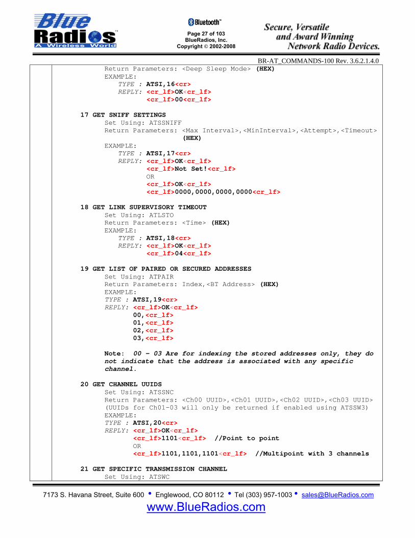
Return Parameters: <Deep Sleep Mode> (HEX) EXAMPLE:
TYPE : ATSI,16<cr> REPLY: <cr_lf>OK<cr_lf> <cr_lf>00<cr_lf>
17 GET SNIFF SETTINGS
Set Using: ATSSNIFF Return Parameters: <Max Interval>,<MinInterval>,<Attempt>,<Timeout> (HEX) EXAMPLE:
TYPE : ATSI,17<cr> REPLY: <cr_lf>OK<cr_lf> <cr_lf>Not Set!<cr_lf> OR <cr_lf>OK<cr_lf> <cr_lf>0000,0000,0000,0000<cr_lf>
18 GET LINK SUPERVISORY TIMEOUT
Set Using: ATLSTO Return Parameters: <Time> (HEX) EXAMPLE:
TYPE : ATSI,18<cr> REPLY: <cr_lf>OK<cr_lf> <cr_lf>04<cr_lf>
19 GET LIST OF PAIRED OR SECURED ADDRESSES Set Using: ATPAIR Return Parameters: Index,<BT Address> (HEX) EXAMPLE: TYPE : ATSI,19<cr> REPLY: <cr_lf>OK<cr_lf>
00,<cr_lf> 01,<cr_lf> 02,<cr_lf> 03,<cr_lf>
Note: 00 – 03 Are for indexing the stored addresses only, they do not indicate that the address is associated with any specific channel.
20 GET CHANNEL UUIDS Set Using: ATSSNC Return Parameters: <Ch00 UUID>,<Ch01 UUID>,<Ch02 UUID>,<Ch03 UUID> (UUIDs for Ch01-03 will only be returned if enabled using ATSSW3) EXAMPLE: TYPE : ATSI,20<cr> REPLY: <cr_lf>OK<cr_lf>
<cr_lf>1101<cr_lf> //Point to point OR <cr_lf>1101,1101,1101<cr_lf> //Multipoint with 3 channels
21 GET SPECIFIC TRANSMISSION CHANNEL
Set Using: ATSWC

Page 28 of 103
BlueRadios, Inc. Copyright © 2002-2008
BR-AT_COMMANDS-100 Rev. 3.6.2.1.4.0
7173 S. Havana Street, Suite 600 • Englewood, CO 80112 • Tel (303) 957-1003 • [email protected]
www.BlueRadios.com
Return Parameters: <Selected>,<Channel> EXAMPLE: TYPE : ATSI,21<cr> REPLY: <cr_lf>OK<cr_lf> <cr_lf>01,03<cr_lf>
22 GET FTP/OPP CONNECTION STATUS Return Parameters: <Connection Status>
Connection Status: 0 = Disconnected, 1 = Connected EXAMPLE: TYPE : ATSI,22<cr> REPLY: <cr_lf>OK<cr_lf> <cr_lf>1<cr_lf>
23 GET TXTEST, TXDATA1, and TXDATA2 SETTINGS ref. Appendix D Return Parameters: <lowfreq>,<level>,modFreq,<storeflag> for TXDATA (HEX)
<lowfreq>,<level>,<storeflag> for TXDATA1 (HEX) <countrycode>,<level>,<storeflag> for TXDATA2 (HEX)
EXAMPLE: TYPE : ATSI,23<cr> REPLY: <cr_lf>OK<cr_lf> <cr_lf>0000,0000,0000,0000<cr_lf> <cr_lf>0000,0000,0000<cr_lf> <cr_lf>0000,0000,0000<cr_lf>
3.4.2 Boot Mode SSW,1 SET BOOT MODE
Function: Sets the boot mode. Format: ATSSW,1,<Boot Mode> Parameters:
Boot Mode: 0 = VM Mode // Default baud rate = 9600, 8-N-1 1 = HCI Mode // Fixed baud rate = 115.2k, 8-N-1 2 = BCSP Mode // Fixed baud rate = 115.2k, 8-N-1
Factory Default: VM Mode
EXAMPLE: TYPE : ATSSW,1,1<cr> REPLY: <cr_lf>OK<cr_lf> OR <cr_lf>ERROR<cr_lf> Read Using: ATRSW,1 Note: All AT Commands work only with the VM.

Page 29 of 103
BlueRadios, Inc. Copyright © 2002-2008
BR-AT_COMMANDS-100 Rev. 3.6.2.1.4.0
7173 S. Havana Street, Suite 600 • Englewood, CO 80112 • Tel (303) 957-1003 • [email protected]
www.BlueRadios.com
RSW,1 READ BOOT MODE
Function: Gets the boot mode. Format: ATRSW,1 Return Parameters: <Boot Mode> EXAMPLE: TYPE : ATRSW,1<cr> REPLY: <cr_lf>OK<cr_lf> <cr_lf>00<cr_lf> Set Using: ATSSW,1
3.4.3 Security Level SSW,2 SET SECURITY LEVEL
Function: Sets the Security Level register state. Format: ATSSW,2,<Security Level> Parameters:
Security Modes: 0 = Link Level – Highest level of security. 1 = Service Level – Provides service information without using PIN.
Factory Default: VM Mode
EXAMPLE: TYPE : ATSSW,2,1<cr> REPLY: <cr_lf>OK<cr_lf> OR <cr_lf>ERROR<cr_lf> Read Using: ATRSW,2
RSW,2 SECURITY LEVEL Function: Gets the Security level register state. Format: ATRSW,2 Return Parameters: <Boot Mode> EXAMPLE: TYPE : ATRSW,2<cr> REPLY: <cr_lf>OK<cr_lf> <cr_lf>00<cr_lf>
Page 30 of 103
BlueRadios, Inc. Copyright © 2002-2008
BR-AT_COMMANDS-100 Rev. 3.6.2.1.4.0
7173 S. Havana Street, Suite 600 • Englewood, CO 80112 • Tel (303) 957-1003 • [email protected]
www.BlueRadios.com
Set Using: ATSSW,2
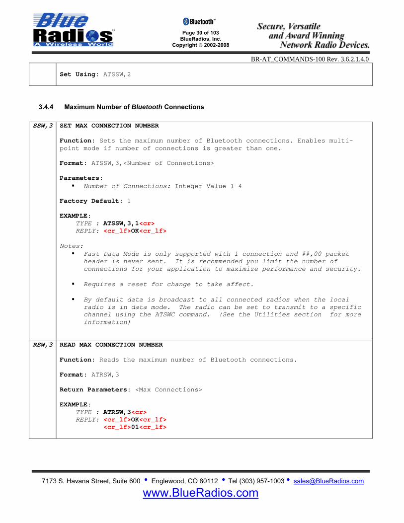
3.4.4 Maximum Number of Bluetooth Connections SSW,3 SET MAX CONNECTION NUMBER
Function: Sets the maximum number of Bluetooth connections. Enables multi-point mode if number of connections is greater than one. Format: ATSSW,3,<Number of Connections> Parameters:
Number of Connections: Integer Value 1-4 Factory Default: 1 EXAMPLE: TYPE : ATSSW,3,1<cr> REPLY: <cr_lf>OK<cr_lf> Notes:
Fast Data Mode is only supported with 1 connection and ##,00 packet header is never sent. It is recommended you limit the number of connections for your application to maximize performance and security.
Requires a reset for change to take affect.
By default data is broadcast to all connected radios when the local
radio is in data mode. The radio can be set to transmit to a specific channel using the ATSWC command. (See the Utilities section for more information)
RSW,3 READ MAX CONNECTION NUMBER Function: Reads the maximum number of Bluetooth connections. Format: ATRSW,3 Return Parameters: <Max Connections> EXAMPLE: TYPE : ATRSW,3<cr> REPLY: <cr_lf>OK<cr_lf> <cr_lf>01<cr_lf>
Page 31 of 103
BlueRadios, Inc. Copyright © 2002-2008
BR-AT_COMMANDS-100 Rev. 3.6.2.1.4.0
7173 S. Havana Street, Suite 600 • Englewood, CO 80112 • Tel (303) 957-1003 • [email protected]
www.BlueRadios.com
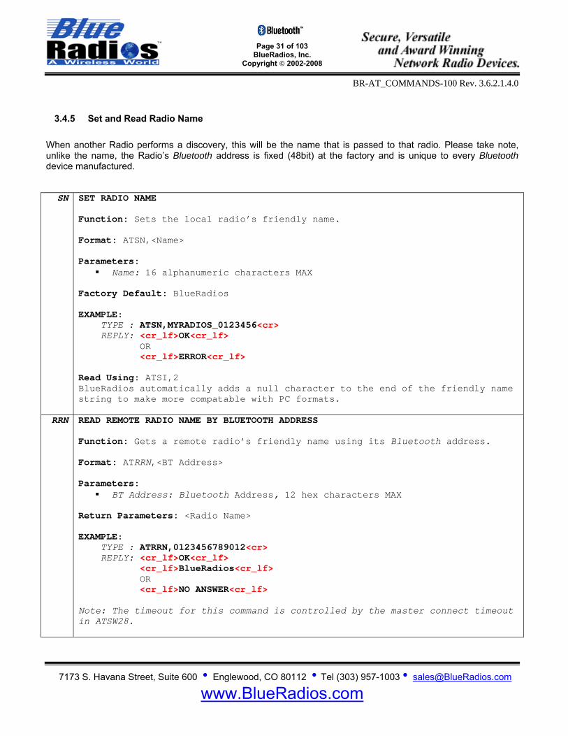
3.4.5 Set and Read Radio Name When another Radio performs a discovery, this will be the name that is passed to that radio. Please take note, unlike the name, the Radio’s Bluetooth address is fixed (48bit) at the factory and is unique to every Bluetooth device manufactured.
SN SET RADIO NAME Function: Sets the local radio’s friendly name. Format: ATSN,<Name> Parameters:
Name: 16 alphanumeric characters MAX Factory Default: BlueRadios EXAMPLE: TYPE : ATSN,MYRADIOS_0123456<cr> REPLY: <cr_lf>OK<cr_lf> OR <cr_lf>ERROR<cr_lf> Read Using: ATSI,2 BlueRadios automatically adds a null character to the end of the friendly name string to make more compatable with PC formats.
RRN
READ REMOTE RADIO NAME BY BLUETOOTH ADDRESS Function: Gets a remote radio’s friendly name using its Bluetooth address. Format: ATRRN,<BT Address> Parameters:
BT Address: Bluetooth Address, 12 hex characters MAX Return Parameters: <Radio Name> EXAMPLE: TYPE : ATRRN,0123456789012<cr> REPLY: <cr_lf>OK<cr_lf> <cr_lf>BlueRadios<cr_lf> OR <cr_lf>NO ANSWER<cr_lf> Note: The timeout for this command is controlled by the master connect timeout in ATSW28.
Page 32 of 103
BlueRadios, Inc. Copyright © 2002-2008
BR-AT_COMMANDS-100 Rev. 3.6.2.1.4.0
7173 S. Havana Street, Suite 600 • Englewood, CO 80112 • Tel (303) 957-1003 • [email protected]
www.BlueRadios.com
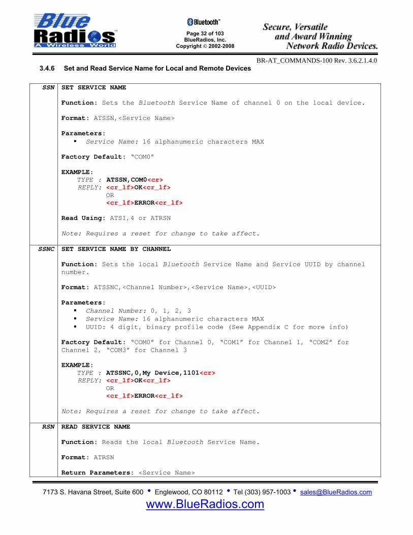
3.4.6 Set and Read Service Name for Local and Remote Devices
SSN SET SERVICE NAME Function: Sets the Bluetooth Service Name of channel 0 on the local device. Format: ATSSN,<Service Name> Parameters:
Service Name: 16 alphanumeric characters MAX Factory Default: “COM0” EXAMPLE: TYPE : ATSSN,COM0<cr> REPLY: <cr_lf>OK<cr_lf> OR <cr_lf>ERROR<cr_lf> Read Using: ATSI,4 or ATRSN Note: Requires a reset for change to take affect.
SSNC SET SERVICE NAME BY CHANNEL Function: Sets the local Bluetooth Service Name and Service UUID by channel number. Format: ATSSNC,<Channel Number>,<Service Name>,<UUID> Parameters:
Channel Number: 0, 1, 2, 3 Service Name: 16 alphanumeric characters MAX UUID: 4 digit, binary profile code (See Appendix C for more info)
Factory Default: “COM0” for Channel 0, “COM1” for Channel 1, “COM2” for Channel 2, “COM3” for Channel 3 EXAMPLE: TYPE : ATSSNC,0,My Device,1101<cr> REPLY: <cr_lf>OK<cr_lf> OR <cr_lf>ERROR<cr_lf> Note: Requires a reset for change to take affect.
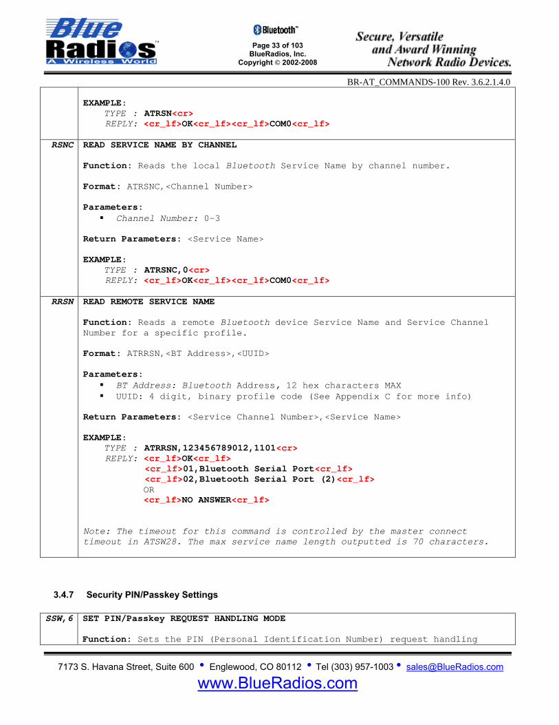
RSN READ SERVICE NAME Function: Reads the local Bluetooth Service Name. Format: ATRSN Return Parameters: <Service Name>
Page 33 of 103
BlueRadios, Inc. Copyright © 2002-2008
BR-AT_COMMANDS-100 Rev. 3.6.2.1.4.0
7173 S. Havana Street, Suite 600 • Englewood, CO 80112 • Tel (303) 957-1003 • [email protected]
www.BlueRadios.com
EXAMPLE: TYPE : ATRSN<cr> REPLY: <cr_lf>OK<cr_lf><cr_lf>COM0<cr_lf>
RSNC READ SERVICE NAME BY CHANNEL Function: Reads the local Bluetooth Service Name by channel number. Format: ATRSNC,<Channel Number> Parameters:
Channel Number: 0-3 Return Parameters: <Service Name> EXAMPLE: TYPE : ATRSNC,0<cr> REPLY: <cr_lf>OK<cr_lf><cr_lf>COM0<cr_lf>
RRSN READ REMOTE SERVICE NAME Function: Reads a remote Bluetooth device Service Name and Service Channel Number for a specific profile. Format: ATRRSN,<BT Address>,<UUID> Parameters:
BT Address: Bluetooth Address, 12 hex characters MAX UUID: 4 digit, binary profile code (See Appendix C for more info)
Return Parameters: <Service Channel Number>,<Service Name> EXAMPLE: TYPE : ATRRSN,123456789012,1101<cr> REPLY: <cr_lf>OK<cr_lf>
<cr_lf>01,Bluetooth Serial Port<cr_lf> <cr_lf>02,Bluetooth Serial Port (2)<cr_lf>
OR <cr_lf>NO ANSWER<cr_lf>
Note: The timeout for this command is controlled by the master connect timeout in ATSW28. The max service name length outputted is 70 characters.
3.4.7 Security PIN/Passkey Settings SSW,6 SET PIN/Passkey REQUEST HANDLING MODE
Function: Sets the PIN (Personal Identification Number) request handling
Page 34 of 103
BlueRadios, Inc. Copyright © 2002-2008
BR-AT_COMMANDS-100 Rev. 3.6.2.1.4.0
7173 S. Havana Street, Suite 600 • Englewood, CO 80112 • Tel (303) 957-1003 • [email protected]
www.BlueRadios.com
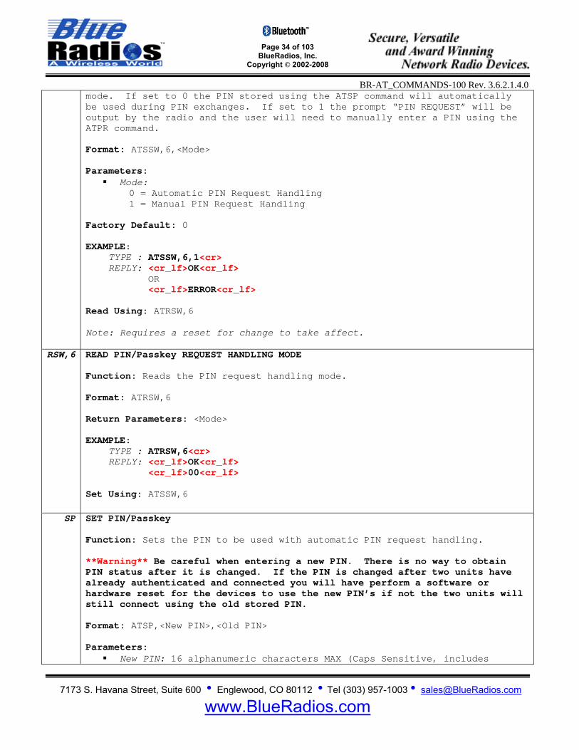
mode. If set to 0 the PIN stored using the ATSP command will automatically be used during PIN exchanges. If set to 1 the prompt “PIN REQUEST” will be output by the radio and the user will need to manually enter a PIN using the ATPR command. Format: ATSSW,6,<Mode> Parameters:
Mode: 0 = Automatic PIN Request Handling 1 = Manual PIN Request Handling
Factory Default: 0
EXAMPLE: TYPE : ATSSW,6,1<cr> REPLY: <cr_lf>OK<cr_lf> OR <cr_lf>ERROR<cr_lf> Read Using: ATRSW,6 Note: Requires a reset for change to take affect.
RSW,6 READ PIN/Passkey REQUEST HANDLING MODE Function: Reads the PIN request handling mode. Format: ATRSW,6 Return Parameters: <Mode> EXAMPLE: TYPE : ATRSW,6<cr> REPLY: <cr_lf>OK<cr_lf> <cr_lf>00<cr_lf> Set Using: ATSSW,6
SP SET PIN/Passkey Function: Sets the PIN to be used with automatic PIN request handling. **Warning** Be careful when entering a new PIN. There is no way to obtain PIN status after it is changed. If the PIN is changed after two units have already authenticated and connected you will have perform a software or hardware reset for the devices to use the new PIN’s if not the two units will still connect using the old stored PIN. Format: ATSP,<New PIN>,<Old PIN> Parameters:
New PIN: 16 alphanumeric characters MAX (Caps Sensitive, includes

Page 35 of 103
BlueRadios, Inc. Copyright © 2002-2008
BR-AT_COMMANDS-100 Rev. 3.6.2.1.4.0
7173 S. Havana Street, Suite 600 • Englewood, CO 80112 • Tel (303) 957-1003 • [email protected]
www.BlueRadios.com
spaces) Old PIN: 16 alphanumeric characters MAX (Caps Sensitive, includes
spaces) Factory Default: default EXAMPLE: TYPE : ATSP,1234567890123456,default<cr> REPLY: <cr_lf>OK<cr_lf> OR <cr_lf>ERROR<cr_lf> Note: If security is enabled in multipoint mode, all connected slaves will have to use the same PIN. There is no way to assign an individual PIN to each slave.
OP OVERWRITE PIN/Passkey Function: Overwrites the stored PIN without needing the old PIN. To use this command the PIN must be unlocked using ATSW29. Format: ATOP,<PIN> Parameters:
PIN: 16 alphanumeric characters MAX (Caps Sensitive, includes spaces) EXAMPLE: TYPE : ATOP,1234<cr> REPLY: <cr_lf>OK<cr_lf> OR <cr_lf>ERROR<cr_lf> //If ATOP has not been enabled with ATSW29
PR RESPOND TO MANUAL PIN/Passkey REQUEST Function: Allows the user to manually enter a PIN after receiving the PIN REQUEST prompt from the radio. Format: ATPR,<PIN> Parameters:
PIN: 16 alphanumeric characters MAX (Caps Sensitive, includes spaces) EXAMPLE: REPLY: <cr_lf>PIN REQUEST<cr_lf> TYPE : ATPR,default<cr> REPLY: <cr_lf>OK<cr_lf> OR <cr_lf>ERROR<cr_lf>

Page 36 of 103
BlueRadios, Inc. Copyright © 2002-2008
BR-AT_COMMANDS-100 Rev. 3.6.2.1.4.0
7173 S. Havana Street, Suite 600 • Englewood, CO 80112 • Tel (303) 957-1003 • [email protected]
www.BlueRadios.com
3.4.8 Class of Device (COD) SC SET COD
Function: Sets the COD. Format: ATSC,<COD> Parameters:
COD: Exactly 8, 16-bit hex values (0 thru F) based on the Bluetooth COD specification names published and maintained by the Bluetooth SIG.
Factory Default: 00000000 – Which is undefined since this is set by the user
based on the final OEM device it is installed in. EXAMPLE: TYPE : ATSC,00020114<cr> REPLY: <cr_lf>OK<cr_lf> OR <cr_lf>ERROR<cr_lf> Read Using: ATSI,5 Note: Requires a reset for change to take affect.
3.4.9 Write Memory Locations (S Registers) – Radio Configuration S registers refer to memory locations used for configuration. The SW commands are used to assign values to various registers in the radio’s flash memory that are stored in nonvolatile memory. SW20 WRITE UART SETTINGS
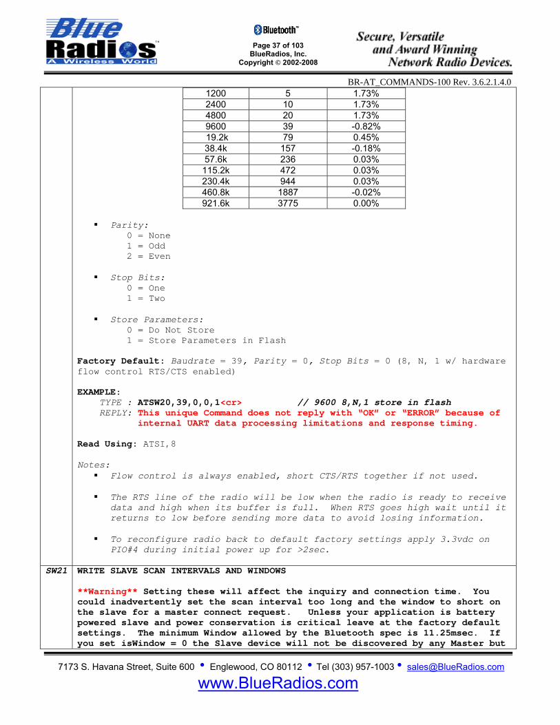
Function: Configures UART settings. Format: ATSW20,<Baudrate>,<Parity>,<Stop Bits>,<Store>
Parameters: Baudrate: 1200 – 921.6Kbps, enter Ascii Value from table below.
**Contact BlueRadios for calculating and setting custom baud rates not listed in the table. As long as the the equation BAUDRATE *0.004096 produces an integer value, then there will be 0% error in clocking for the baud rate.
Baudrate Ascii Value Error
No Change 0 -
Page 37 of 103
BlueRadios, Inc. Copyright © 2002-2008
BR-AT_COMMANDS-100 Rev. 3.6.2.1.4.0
7173 S. Havana Street, Suite 600 • Englewood, CO 80112 • Tel (303) 957-1003 • [email protected]
www.BlueRadios.com
1200 5 1.73% 2400 10 1.73% 4800 20 1.73% 9600 39 -0.82% 19.2k 79 0.45% 38.4k 157 -0.18% 57.6k 236 0.03% 115.2k 472 0.03% 230.4k 944 0.03% 460.8k 1887 -0.02% 921.6k 3775 0.00%
Parity: 0 = None 1 = Odd 2 = Even
Stop Bits: 0 = One 1 = Two
Store Parameters: 0 = Do Not Store 1 = Store Parameters in Flash
Factory Default: Baudrate = 39, Parity = 0, Stop Bits = 0 (8, N, 1 w/ hardware flow control RTS/CTS enabled) EXAMPLE: TYPE : ATSW20,39,0,0,1<cr> // 9600 8,N,1 store in flash REPLY: This unique Command does not reply with “OK” or “ERROR” because of internal UART data processing limitations and response timing. Read Using: ATSI,8 Notes:
Flow control is always enabled, short CTS/RTS together if not used. The RTS line of the radio will be low when the radio is ready to receive
data and high when its buffer is full. When RTS goes high wait until it returns to low before sending more data to avoid losing information.
To reconfigure radio back to default factory settings apply 3.3vdc on
PIO#4 during initial power up for >2sec.
SW21 WRITE SLAVE SCAN INTERVALS AND WINDOWS **Warning** Setting these will affect the inquiry and connection time. You could inadvertently set the scan interval too long and the window to short on the slave for a master connect request. Unless your application is battery powered slave and power conservation is critical leave at the factory default settings. The minimum Window allowed by the Bluetooth spec is 11.25msec. If you set isWindow = 0 the Slave device will not be discovered by any Master but
Page 38 of 103
BlueRadios, Inc. Copyright © 2002-2008
BR-AT_COMMANDS-100 Rev. 3.6.2.1.4.0
7173 S. Havana Street, Suite 600 • Englewood, CO 80112 • Tel (303) 957-1003 • [email protected]
www.BlueRadios.com
you can still use the Slaves BT address and connect directly to it from a remote Master. Function: Configures Page Scan and Inquiry Scan Interval and Window for disconnected slave devices in time slots. Format: ATSW21,<psInterval>,<psWindow>,<isInterval>,<isWindow> Parameters:
psInterval: Page Scan Interval Integer Value 18 to 4096 (11.25ms to 2560ms) Time [ms] = psInterval * 0.625ms psWindow: Page Scan Window Integer Value 18 to 4096 (11.25ms to 2560ms) Time [ms] = psWindow * 0.625ms isInterval: Inquiry Scan Interval Integer Value 18 to 4096 (11.25ms to 2560ms) Time [ms] = isInterval * 0.625ms isWindow: Inquiry Scan Window Integer Value 18 to 4096 (11.25ms to 2560ms) Time [ms] = isWindow * 0.625ms
Factory Default: psInterval = 1024(640ms), psWindow = 512(320ms), isInterval = 1024(640ms), isWindow = 512(320ms) EXAMPLE: TYPE : ATSW21,4096,18,4096,18<cr> REPLY: <cr_lf>OK<cr_lf> OR <cr_lf>ERROR<cr_lf> Read Using: ATSI,10 Notes:
Requires a reset for the settings to go into affect. ATSW21,4096,18,4096,18 settings will result in a current draw for an
unconnected slave of ~1mA average vs. 39mA average at default setting. Which is 1% vs. 50% respectively lower reciver duty cycle.
ATSW21,4096,18,4096,18 settings along with enabling Deep Sleep Mode will
result in an unconnected slave current draw of ≈ 350uA average.
By lowering the window value, power can be saved at the expense of possibly missing an inquiry or page. Since the host usually retries automatically many times, the only downside is a delay in discovery or connection time.
SW22 WRITE PIO DIRECTION **Warning** This command has to be issued before using PIO’s as outputs.
Page 39 of 103
BlueRadios, Inc. Copyright © 2002-2008
BR-AT_COMMANDS-100 Rev. 3.6.2.1.4.0
7173 S. Havana Street, Suite 600 • Englewood, CO 80112 • Tel (303) 957-1003 • [email protected]
www.BlueRadios.com
Inputting 3.3Vdc into a PIO assigned as output will permanently damage the radio. Function: Configures direction of PIO’s. Format: ATSW22,<PIO#>,<PIO State>,<Store>
Parameters: PIO#: 3,6,7 (6 & 7 not user definable in MP mode, see notes below)
PIO State:
0 = Input 1 = Output
Store: 0 = Do Not Store 1 = Store Parameters in Flash
EXAMPLE: TYPE : ATSW22,6,0,1<cr> REPLY: <cr_lf>OK<cr_lf> OR <cr_lf>ERROR<cr_lf> Notes:
Point to Point PIO Functionality
PIO(2) Hard coded as output only. Indicates Bluetooth connection on Ch00.
PIO(3) Hard coded as input only. High signal of > 1ms will interrupt to
wake-up CPU out of deep sleep mode if enabled.
PIO(4) Hard coded as input only, Triple Purpose PIO. Used for resetting factory defaults on power up and breaking out of Fast Data mode while Bluetooth connected. Also if strobed will auto connect to last paired or last connected device.
PIO(5) Hard coded as output only. Strobes to indicate slave or master
inquiry in process.
PIO(6) User Definable. Defaults as input.
PIO(7) User Definable. Defaults as input.
Multi Point PIO Functionality
PIO(2) Hard coded as output only. Indicates Bluetooth connection on Ch00.
Page 40 of 103
BlueRadios, Inc. Copyright © 2002-2008
BR-AT_COMMANDS-100 Rev. 3.6.2.1.4.0
7173 S. Havana Street, Suite 600 • Englewood, CO 80112 • Tel (303) 957-1003 • [email protected]
www.BlueRadios.com
PIO(3) Hard coded as input only. Defaults as input, high signal of > 1ms will interrupt to wake-up CPU out of deep sleep mode if enabled.
PIO(4) Hard coded as input only, Triple Purpose PIO. Used for resetting
factory defaults on power up and breaking out of Fast Data mode while Bluetooth connected. Also if strobed will auto connect to last paired or last connected device.
PIO(5) Hard coded as output only. Indicates Bluetooth connection on
Ch01.
PIO(6) User definable if no connection on Channel 2. Indicates Bluetooth connection on Ch02.
PIO(7) User definable if no connection on Channel 3. Indicates Bluetooth
connection on Ch03.
SW23 WRITE PIO LEVEL Function: Sets PIO logic level.
Format: ATSW23,<PIO#>,<Value>,<Store> Parameters:
PIO#: 3,6,7 (6 & 7 not user controllable in MP mode, see notes above in ATSW22)
PIO State:
0 = Off (0V) 1 = On (+V)
Store: 0 = Do Not Store 1 = Store Parameters in Flash
EXAMPLE: TYPE : ATSW23,6,1,1<cr> REPLY: <cr_lf>OK<cr_lf> OR <cr_lf>ERROR<cr_lf> Read Using: ATSR21
SW24 WRITE RESPONSE, SECURITY, AUTO SCO, FILTER SETTINGS Function: Configures response, security, auto sco, and filter settings. Format: ATSW24,<Response Type>,<Security>,<Auto SCO>,<Minor Filter> Parameters:
Response Type (See Appendix B for more information): 0 = Long Response
Page 41 of 103
BlueRadios, Inc. Copyright © 2002-2008
BR-AT_COMMANDS-100 Rev. 3.6.2.1.4.0
7173 S. Havana Street, Suite 600 • Englewood, CO 80112 • Tel (303) 957-1003 • [email protected]
www.BlueRadios.com
1 = Short Response 2 = No Verbose Mode (No unsolicited responses will be output)
- No OKs will come back, but requested information such as ATSI, ATRSW, ATRSN and ATDI responses will.
- The radio will not output CONNECT or DISCONNECT messages. - In FTP and OPP modes the radio will still output all necessary
messages such as PUSH START and PUSH COMPLETE. *Security: 56bit encryption is automatically enabled when set to 1.
UART will reply PAIRED,<BT Address> before the CONNECT,<BT Address> is returned when a connection is made.
0 = No Authorization 1 = Authorization Required
Auto SCO: 0 = No Automatic SCO Connect 1 = SCO Auto Connect Upon Radio Connect.
**Minor Filter: 0 = Disable Minor COD Filter on Inquiry 1 = Enable Minor COD Filter on Inquiry
Factory Default: Response Type = 0, Security = 0, Auto SCO = 0, Filter = 0 EXAMPLE: TYPE : ATSW24,0,0,0,0<cr> REPLY: <cr_lf>OK<cr_lf> OR <cr_lf>ERROR<cr_lf> Read Using: ATSI,6 Notes:
See Appendix B for differences between short response and long response mode.
Requires a reset for security to go into affect. *If security is enabled in multipoint mode, all connected slaves will
have to use the same PIN. There is no way to assign an individual PIN to each slave.
**With the minor filter enabled, inquiry results are filtered by the
lower 2 bytes of the COD. If the minor filter is disabled all devices are found.
SW25 WRITE CONNECTION, COMM, UNCONNECTED UART, DEFAULT SERVICE MODES
**Warning** The only way to communicate to the radio after setting the radio in “Fast Data Mode” and “ignore UART while unconnected” is to apply 3.3Vdc on PIO(4) during initial power up for >2 sec. These settings are used if you have no control over the source of streaming data into the radio, or you do not know when the radio has made a Bluetooth connection, and do not plan on
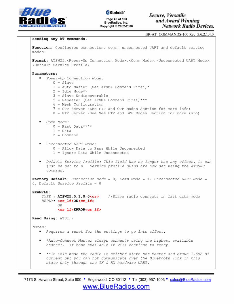
Page 42 of 103
BlueRadios, Inc. Copyright © 2002-2008
BR-AT_COMMANDS-100 Rev. 3.6.2.1.4.0
7173 S. Havana Street, Suite 600 • Englewood, CO 80112 • Tel (303) 957-1003 • [email protected]
www.BlueRadios.com
sending any AT commands. Function: Configures connection, comm, unconnected UART and default service modes. Format: ATSW25,<Power-Up Connection Mode>,<Comm Mode>,<Unconnected UART Mode>, <Default Service Profile> Parameters:
Power-Up Connection Mode: 0 = Slave 1 = Auto-Master (Set ATSMA Command First)* 2 = Idle Mode** 3 = Slave Undiscoverable 5 = Repeater (Set ATSMA Command First)*** 6 = Mesh Configuration
7 = OPP Server (See FTP and OPP Modes Section for more info) 8 = FTP Server (See See FTP and OPP Modes Section for more info)
Comm Mode: 0 = Fast Data**** 1 = Data 2 = Command
Unconnected UART Mode: 0 = Allow Data to Pass While Unconnected 1 = Ignore Data While Unconnected Default Service Profile: This field has no longer has any effect, it can
just be set to 0. Service profile UUIDs are now set using the ATSSNC command.
Factory Default: Connection Mode = 0, Comm Mode = 1, Unconnected UART Mode = 0, Default Service Profile = 0 EXAMPLE: TYPE : ATSW25,0,1,0,0<cr> //Slave radio connects in fast data mode REPLY: <cr_lf>OK<cr_lf> OR <cr_lf>ERROR<cr_lf> Read Using: ATSI,7 Notes:
Requires a reset for the settings to go into affect.
*Auto-Connect Master always connects using the highest available channel. If none available it will continue to retry.
**In idle mode the radio is neither slave nor master and draws 1.6mA of
current but you can not communicate over the Bluetooth link in this state only through the TX & RX hardware UART.

Page 43 of 103
BlueRadios, Inc. Copyright © 2002-2008
BR-AT_COMMANDS-100 Rev. 3.6.2.1.4.0
7173 S. Havana Street, Suite 600 • Englewood, CO 80112 • Tel (303) 957-1003 • [email protected]
www.BlueRadios.com
***Repeater always uses channel 00 for slave and 01 for Master. Repeater also only uses SPP with no SCO connection.
****If data mode is set to “Fast Data Mode” in a Master unit during a
manual inquiry “ATDI” and/or connection request the radio connects in slow data mode not fast. This is because you will need the capability to issue commands because in fast data mode the AT command parser is turned off.
The comm mode parameter has no effect when operating in FTP or OPP mode.
SW26 LOCK USER SETTINGS
**Warning** This command will lock the PIN. Function: Locks user settings to prevent unauthorized local & remote access. Format: ATSW26,<PIN>,<Lock/Unlock> Parameters:
PIN: 16 alphanumeric characters MAX (Caps Sensitive, includes spaces)
Lock/Unlock: 0 = Unlocked 1 = Locked
Factory Default: Unlocked EXAMPLE: TYPE : ATSW26,default,1<cr> REPLY: <cr_lf>OK<cr_lf> OR <cr_lf>ERROR<cr_lf> Note: ATSW26 will still work after locking the user settings, allowing them to be unlocked. Only works with 10 character PINs or less.
SW27 WRITE LED RATE Function: Sets the LED Pulse Rate on PIO(5). Format: ATSW27,<Pulse Period> Parameters:
Pulse Rate: Integer decimal value from 1ms to 60,000ms Factory Default: 1000 EXAMPLE: TYPE : ATSW27,1000<cr> //1000 ms REPLY: <cr_lf>OK<cr_lf>
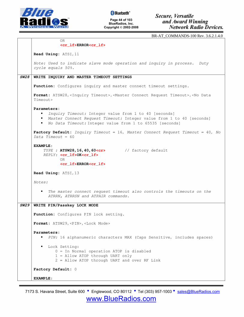
Page 44 of 103
BlueRadios, Inc. Copyright © 2002-2008
BR-AT_COMMANDS-100 Rev. 3.6.2.1.4.0
7173 S. Havana Street, Suite 600 • Englewood, CO 80112 • Tel (303) 957-1003 • [email protected]
www.BlueRadios.com
OR <cr_lf>ERROR<cr_lf> Read Using: ATSI,11 Note: Used to indicate slave mode operation and inquiry in process. Duty cycle equals 50%.
SW28 WRITE INQUIRY AND MASTER TIMEOUT SETTINGS Function: Configures inquiry and master connect timeout settings. Format: ATSW28,<Inquiry Timeout>,<Master Connect Request Timeout>,<No Data Timeout> Parameters:
Inquiry Timeout: Integer value from 1 to 40 [seconds] Master Connect Request Timeout: Integer value from 1 to 40 [seconds] No Data Timeout: Integer value from 1 to 65535 [seconds]
Factory Default: Inquiry Timeout = 16, Master Connect Request Timeout = 40, No Data Timeout = 60 EXAMPLE: TYPE : ATSW28,16,40,60<cr> // factory default REPLY: <cr_lf>OK<cr_lf> OR <cr_lf>ERROR<cr_lf> Read Using: ATSI,13 Notes:
The master connect request timeout also controls the timeouts on the ATRRN, ATRRSN and ATPAIR commands.
SW29 WRITE PIN/Passkey LOCK MODE
Function: Configures PIN lock setting. Format: ATSW29,<PIN>,<Lock Mode> Parameters:
PIN: 16 alphanumeric characters MAX (Caps Sensitive, includes spaces)
Lock Setting: 0 = In Normal operation ATOP is disabled
1 = Allow ATOP through UART only 2 = Allow ATOP through UART and over RF Link Factory Default: 0 EXAMPLE:

Page 45 of 103
BlueRadios, Inc. Copyright © 2002-2008
BR-AT_COMMANDS-100 Rev. 3.6.2.1.4.0
7173 S. Havana Street, Suite 600 • Englewood, CO 80112 • Tel (303) 957-1003 • [email protected]
www.BlueRadios.com
TYPE : ATSW29,default,1<cr> REPLY: <cr_lf>OK<cr_lf> OR <cr_lf>ERROR<cr_lf> Read Using: ATSI,15 Note: This command enables ATOP, described in the Security PIN Settings section.
SW30 WRITE DEEP SLEEP MODE Function: Configures deep sleep mode. Format: ATSW30,<Deep Sleep Mode> Parameters:
Deep Sleep Mode: 0 = Normal Operation never go into deep sleep
1 = Go into deep sleep whenever possible (While idle, page scan or sniff mode)
Factory Default: 0 EXAMPLE: TYPE : ATSW30,1<cr> REPLY: <cr_lf>OK<cr_lf> OR <cr_lf>ERROR<cr_lf> Read Using: ATSI,16 Notes:
When the radio is in deep sleep you can not discover or connect to it.
The UART RX line needs to be pulled high if not active before power is applied to the radio module.
If there is an active UART RF link the device will need Sniff Mode
enabled to allow it to drop into sleep mode when there is no traffic.
When in deep sleep, the UART will miss the first character while waking up. Send a preamble byte to allow it to wake up and immediately thereafter send the AT Command or data in less than 1 second or the device will go back to deep sleep again. If you are using PIO(3) CPU interrupt a preamble byte is not needed.
No bytes are lost if sending commands down over the remote RF link side.
This setting is stored in flash and does not require a reset to take
affect. Takes approx. 1 second before the current will drop down to 25-50uA. Allow 5msec. for the CPU unit to come out of deep sleep.
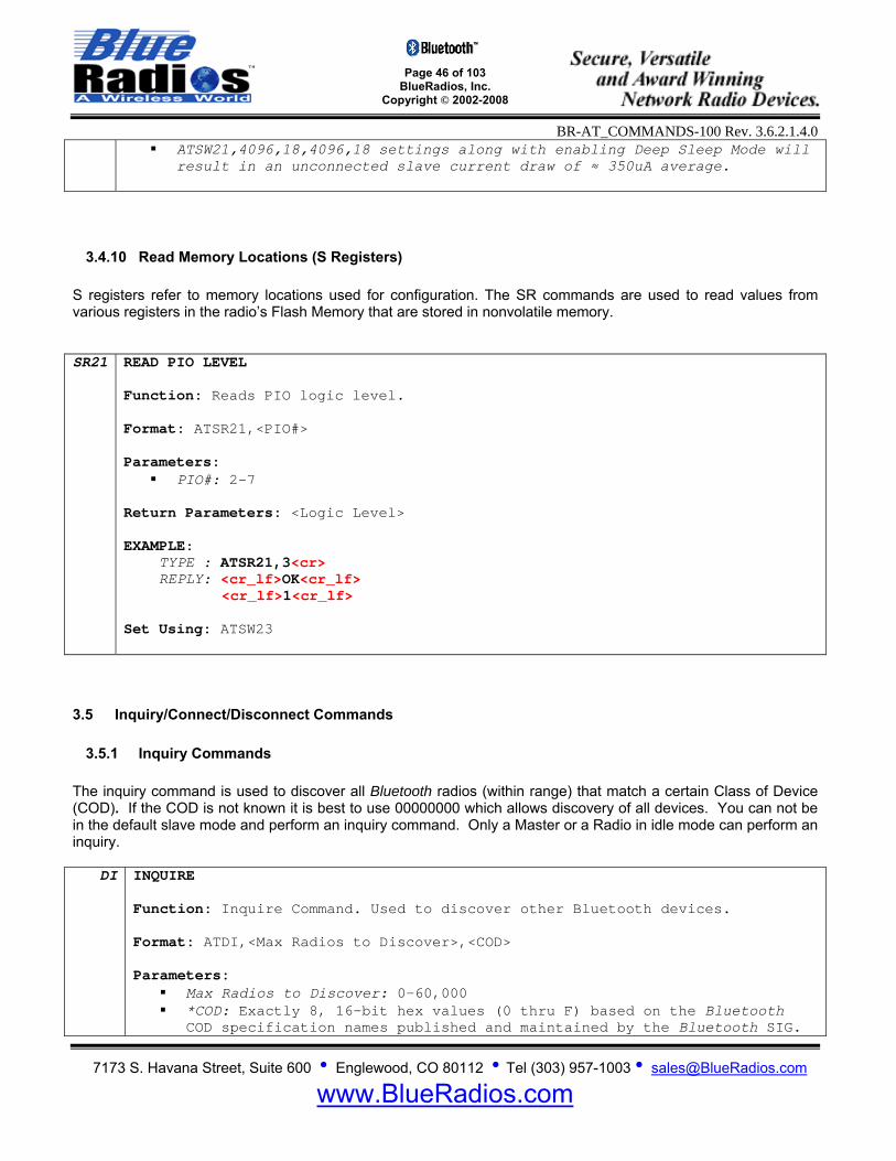
Page 46 of 103
BlueRadios, Inc. Copyright © 2002-2008
BR-AT_COMMANDS-100 Rev. 3.6.2.1.4.0
7173 S. Havana Street, Suite 600 • Englewood, CO 80112 • Tel (303) 957-1003 • [email protected]
www.BlueRadios.com
ATSW21,4096,18,4096,18 settings along with enabling Deep Sleep Mode will result in an unconnected slave current draw of ≈ 350uA average.
3.4.10 Read Memory Locations (S Registers) S registers refer to memory locations used for configuration. The SR commands are used to read values from various registers in the radio’s Flash Memory that are stored in nonvolatile memory. SR21 READ PIO LEVEL
Function: Reads PIO logic level. Format: ATSR21,<PIO#> Parameters:
PIO#: 2-7
Return Parameters: <Logic Level> EXAMPLE: TYPE : ATSR21,3<cr> REPLY: <cr_lf>OK<cr_lf>
<cr_lf>1<cr_lf>
Set Using: ATSW23
3.5 Inquiry/Connect/Disconnect Commands
3.5.1 Inquiry Commands The inquiry command is used to discover all Bluetooth radios (within range) that match a certain Class of Device (COD). If the COD is not known it is best to use 00000000 which allows discovery of all devices. You can not be in the default slave mode and perform an inquiry command. Only a Master or a Radio in idle mode can perform an inquiry.
DI INQUIRE Function: Inquire Command. Used to discover other Bluetooth devices. Format: ATDI,<Max Radios to Discover>,<COD> Parameters:
Max Radios to Discover: 0-60,000 *COD: Exactly 8, 16-bit hex values (0 thru F) based on the Bluetooth
COD specification names published and maintained by the Bluetooth SIG.
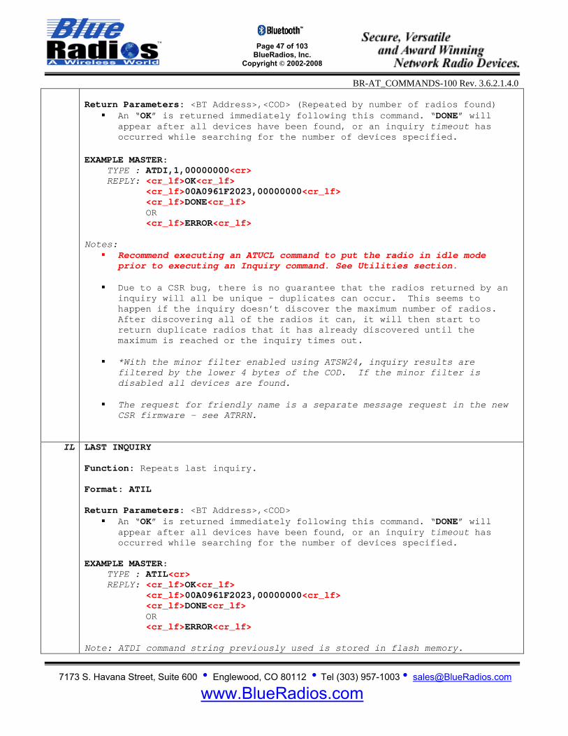
Page 47 of 103
BlueRadios, Inc. Copyright © 2002-2008
BR-AT_COMMANDS-100 Rev. 3.6.2.1.4.0
7173 S. Havana Street, Suite 600 • Englewood, CO 80112 • Tel (303) 957-1003 • [email protected]
www.BlueRadios.com
Return Parameters: <BT Address>,<COD> (Repeated by number of radios found)
An “OK” is returned immediately following this command. “DONE” will appear after all devices have been found, or an inquiry timeout has occurred while searching for the number of devices specified.
EXAMPLE MASTER: TYPE : ATDI,1,00000000<cr> REPLY: <cr_lf>OK<cr_lf> <cr_lf>00A0961F2023,00000000<cr_lf> <cr_lf>DONE<cr_lf> OR <cr_lf>ERROR<cr_lf> Notes:
Recommend executing an ATUCL command to put the radio in idle mode prior to executing an Inquiry command. See Utilities section.
Due to a CSR bug, there is no guarantee that the radios returned by an
inquiry will all be unique – duplicates can occur. This seems to happen if the inquiry doesn’t discover the maximum number of radios. After discovering all of the radios it can, it will then start to return duplicate radios that it has already discovered until the maximum is reached or the inquiry times out.
*With the minor filter enabled using ATSW24, inquiry results are
filtered by the lower 4 bytes of the COD. If the minor filter is disabled all devices are found.
The request for friendly name is a separate message request in the new
CSR firmware – see ATRRN.
IL LAST INQUIRY Function: Repeats last inquiry. Format: ATIL Return Parameters: <BT Address>,<COD>
An “OK” is returned immediately following this command. “DONE” will appear after all devices have been found, or an inquiry timeout has occurred while searching for the number of devices specified.
EXAMPLE MASTER: TYPE : ATIL<cr> REPLY: <cr_lf>OK<cr_lf> <cr_lf>00A0961F2023,00000000<cr_lf> <cr_lf>DONE<cr_lf> OR <cr_lf>ERROR<cr_lf> Note: ATDI command string previously used is stored in flash memory.
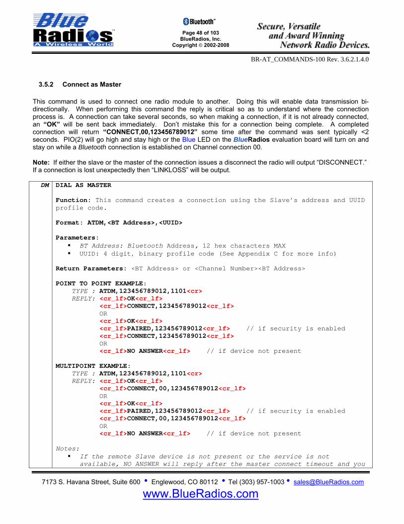
Page 48 of 103
BlueRadios, Inc. Copyright © 2002-2008
BR-AT_COMMANDS-100 Rev. 3.6.2.1.4.0
7173 S. Havana Street, Suite 600 • Englewood, CO 80112 • Tel (303) 957-1003 • [email protected]
www.BlueRadios.com
3.5.2 Connect as Master This command is used to connect one radio module to another. Doing this will enable data transmission bi-directionally. When performing this command the reply is critical so as to understand where the connection process is. A connection can take several seconds, so when making a connection, if it is not already connected, an “OK” will be sent back immediately. Don’t mistake this for a connection being complete. A completed connection will return “CONNECT,00,123456789012” some time after the command was sent typically <2 seconds. PIO(2) will go high and stay high or the Blue LED on the BlueRadios evaluation board will turn on and stay on while a Bluetooth connection is established on Channel connection 00. Note: If either the slave or the master of the connection issues a disconnect the radio will output “DISCONNECT.” If a connection is lost unexpectedly then “LINKLOSS” will be output.
DM DIAL AS MASTER Function: This command creates a connection using the Slave’s address and UUID profile code. Format: ATDM,<BT Address>,<UUID> Parameters:
BT Address: Bluetooth Address, 12 hex characters MAX UUID: 4 digit, binary profile code (See Appendix C for more info)
Return Parameters: <BT Address> or <Channel Number><BT Address> POINT TO POINT EXAMPLE: TYPE : ATDM,123456789012,1101<cr> REPLY: <cr_lf>OK<cr_lf> <cr_lf>CONNECT,123456789012<cr_lf> OR <cr_lf>OK<cr_lf> <cr_lf>PAIRED,123456789012<cr_lf> // if security is enabled <cr_lf>CONNECT,123456789012<cr_lf> OR <cr_lf>NO ANSWER<cr_lf> // if device not present MULTIPOINT EXAMPLE: TYPE : ATDM,123456789012,1101<cr> REPLY: <cr_lf>OK<cr_lf> <cr_lf>CONNECT,00,123456789012<cr_lf> OR <cr_lf>OK<cr_lf> <cr_lf>PAIRED,123456789012<cr_lf> // if security is enabled <cr_lf>CONNECT,00,123456789012<cr_lf> OR <cr_lf>NO ANSWER<cr_lf> // if device not present Notes:
If the remote Slave device is not present or the service is not available, NO ANSWER will reply after the master connect timeout and you
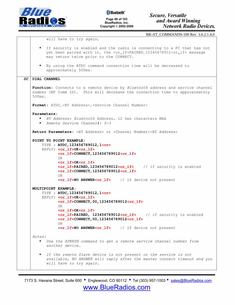
Page 49 of 103
BlueRadios, Inc. Copyright © 2002-2008
BR-AT_COMMANDS-100 Rev. 3.6.2.1.4.0
7173 S. Havana Street, Suite 600 • Englewood, CO 80112 • Tel (303) 957-1003 • [email protected]
www.BlueRadios.com
will have to try again. If security is enabled and the radio is connecting to a PC that has not
yet been paired with it, the <cr_lf>PAIRED,12345678912<cr_lf> message may return twice prior to the CONNECT.
By using the ATDC command connection time will be decreased to
approximately 500ms.
DC DIAL CHANNEL Function: Connects to a remote device by Bluetooth address and service channel number (RF Comm ID). This will decrease the connection time to approximately 500ms. Format: ATDC,<BT Address>,<Service Channel Number> Parameters:
BT Address: Bluetooth Address, 12 hex characters MAX Remote Service Channel#: 0-3
Return Parameters: <BT Address> or <Channel Number><BT Address> POINT TO POINT EXAMPLE: TYPE : ATDC,123456789012,1<cr> REPLY: <cr_lf>OK<cr_lf> <cr_lf>CONNECT,123456789012<cr_lf> OR <cr_lf>OK<cr_lf> <cr_lf>PAIRED,123456789012<cr_lf> // if security is enabled <cr_lf>CONNECT,123456789012<cr_lf> OR <cr_lf>NO ANSWER<cr_lf> // if device not present MULTIPOINT EXAMPLE: TYPE : ATDC,123456789012,1<cr> REPLY: <cr_lf>OK<cr_lf> <cr_lf>CONNECT,00,123456789012<cr_lf> OR <cr_lf>OK<cr_lf> <cr_lf>PAIRED, 123456789012<cr_lf> // if security is enabled <cr_lf>CONNECT,00,123456789012<cr_lf> OR <cr_lf>NO ANSWER<cr_lf> // if device not present Notes:
Use the ATRRSN command to get a remote service channel number from another device.
If the remote Slave device is not present or the service is not
available, NO ANSWER will reply after the master connect timeout and you will have to try again.

Page 50 of 103
BlueRadios, Inc. Copyright © 2002-2008
BR-AT_COMMANDS-100 Rev. 3.6.2.1.4.0
7173 S. Havana Street, Suite 600 • Englewood, CO 80112 • Tel (303) 957-1003 • [email protected]
www.BlueRadios.com
If security is enabled and the radio is connecting to a PC that has not yet been paired with it, the <cr_lf>PAIRED,12345678912<cr_lf> message may return twice prior to the CONNECT.
DMC DIAL AS MASTER BY CHANNEL Function: This command creates a connection using the Slave’s address and UUID profile code, as well as the masters connection channel. Format: ATDMC,<BT Address>,<UUID><Channel Number> Parameters:
BT Address: Bluetooth Address, 12 hex characters MAX UUID: 4 digit, binary profile code (See Appendix C for more info) Channel Number: Local channel to be used for the connection
Return Parameters: <Channel Number><BT Address> MULTIPOINT EXAMPLE: TYPE : ATDMC,123456789012,1101,1<cr> REPLY: <cr_lf>OK<cr_lf> <cr_lf>CONNECT,01,123456789012<cr_lf> OR <cr_lf>OK<cr_lf> <cr_lf>PAIRED,123456789012<cr_lf> // if security is enabled <cr_lf>CONNECT,01,123456789012<cr_lf> OR <cr_lf>NO ANSWER<cr_lf> // if device not present Notes:
If the remote Slave device is not present or the service is not available, NO ANSWER will reply after the master connect timeout and you will have to try again.
If security is enabled and the radio is connecting to a PC that has not
yet been paired with it, the <cr_lf>PAIRED,12345678912<cr_lf> message may return twice prior to the CONNECT.
Not ment to be used in Point to Point mode.
DL DIAL LAST
Function: Connects to last successful Slave Bluetooth address connection over SPP unless ATDM command was executed then the UUID from the ATDM command will be used. Format: ATDL Return Parameters: <BT Address> or <Channel Number><BT Address> POINT TO POINT EXAMPLE: TYPE : ATDL REPLY: <cr_lf>OK<cr_lf>
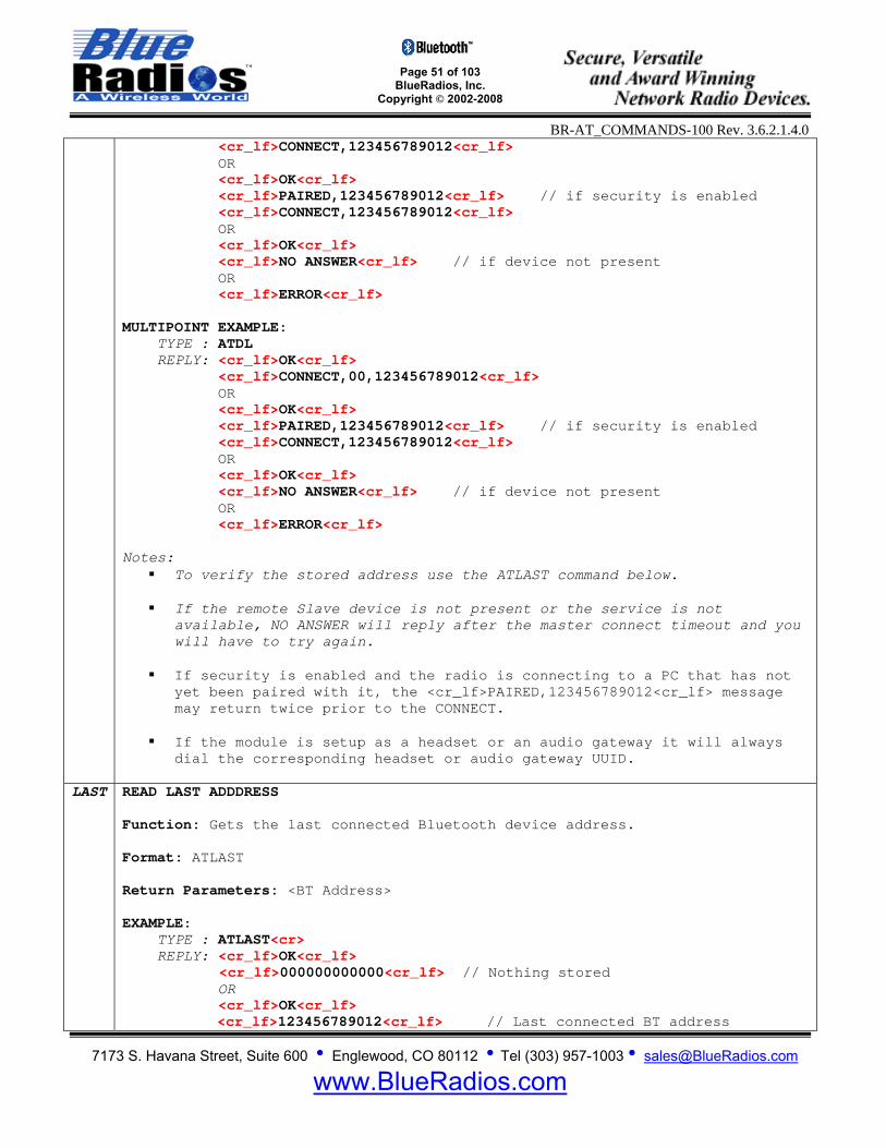
Page 51 of 103
BlueRadios, Inc. Copyright © 2002-2008
BR-AT_COMMANDS-100 Rev. 3.6.2.1.4.0
7173 S. Havana Street, Suite 600 • Englewood, CO 80112 • Tel (303) 957-1003 • [email protected]
www.BlueRadios.com
<cr_lf>CONNECT,123456789012<cr_lf> OR <cr_lf>OK<cr_lf> <cr_lf>PAIRED,123456789012<cr_lf> // if security is enabled <cr_lf>CONNECT,123456789012<cr_lf> OR <cr_lf>OK<cr_lf> <cr_lf>NO ANSWER<cr_lf> // if device not present OR <cr_lf>ERROR<cr_lf> MULTIPOINT EXAMPLE: TYPE : ATDL REPLY: <cr_lf>OK<cr_lf> <cr_lf>CONNECT,00,123456789012<cr_lf> OR <cr_lf>OK<cr_lf> <cr_lf>PAIRED,123456789012<cr_lf> // if security is enabled <cr_lf>CONNECT,123456789012<cr_lf> OR <cr_lf>OK<cr_lf> <cr_lf>NO ANSWER<cr_lf> // if device not present OR <cr_lf>ERROR<cr_lf> Notes:
To verify the stored address use the ATLAST command below. If the remote Slave device is not present or the service is not
available, NO ANSWER will reply after the master connect timeout and you will have to try again.
If security is enabled and the radio is connecting to a PC that has not
yet been paired with it, the <cr_lf>PAIRED,123456789012<cr_lf> message may return twice prior to the CONNECT.
If the module is setup as a headset or an audio gateway it will always
dial the corresponding headset or audio gateway UUID.
LAST READ LAST ADDDRESS Function: Gets the last connected Bluetooth device address. Format: ATLAST Return Parameters: <BT Address> EXAMPLE: TYPE : ATLAST<cr> REPLY: <cr_lf>OK<cr_lf>
<cr_lf>000000000000<cr_lf> // Nothing stored OR <cr_lf>OK<cr_lf>
<cr_lf>123456789012<cr_lf> // Last connected BT address

Page 52 of 103
BlueRadios, Inc. Copyright © 2002-2008
BR-AT_COMMANDS-100 Rev. 3.6.2.1.4.0
7173 S. Havana Street, Suite 600 • Englewood, CO 80112 • Tel (303) 957-1003 • [email protected]
www.BlueRadios.com
3.5.3 Set Master Default Bluetooth Address
SMA
SET MASTER DEFAULT ADDRESS Function: This command will set a specific Bluetooth Slave address and service profile into the Master device so on power up the Master will automatically search and connect to a unique Slave device on the highest available channel. Format: ATSMA,<BT Address>,<UUID> Parameters:
BT Address: Bluetooth Address, 12 hex characters MAX UUID: 4 digit, binary profile code (See Appendix C for more info)
EXAMPLE: TYPE : ATSMA,00A0961F904F,1101<cr> REPLY: <cr_lf>OK<cr_lf> OR <cr_lf>ERROR<cr_lf> Read Using: ATSI,9 Notes:
Execute ATSW25 to set the power up connect mode to auto-master before using the above command if still in slave mode.
This command is limited to only one connection. Reset module for
change to take affect.
MACLR MASTER ADDRESS CLEAR Function: Clears stored slave address. Format: ATMACLR EXAMPLE: TYPE : ATMACLR<cr> REPLY: <cr_lf>OK<cr_lf> OR <cr_lf>ERROR<cr_lf>
SSW,7 SET AUTO CONNECT MASTER ON DATA Function: Connects automatically to the stored master address when data is present on the UART. The Radio will disconnect when the No Data timeout has been reached, this occurs when no data is being sent to the UART. The ATSMA command must be enabled before this will work. See the ATSW28 command to set

Page 53 of 103
BlueRadios, Inc. Copyright © 2002-2008
BR-AT_COMMANDS-100 Rev. 3.6.2.1.4.0
7173 S. Havana Street, Suite 600 • Englewood, CO 80112 • Tel (303) 957-1003 • [email protected]
www.BlueRadios.com
the No Data timeout. Format: ATSSW7,1 EXAMPLE: TYPE : ATSSW,7,1<cr> REPLY: <cr_lf>OK<cr_lf> OR <cr_lf>ERROR<cr_lf>
RSW,7 READ AUTO CONNECT MASTER ON DATA Function: Reads the AUTO CONNECT MASTER ON DATA enable/disable register state. Format: ATRSW,7 Return Parameters: <Enable/Disable> EXAMPLE: TYPE : ATRSW,7<cr> REPLY: <cr_lf>OK<cr_lf> <cr_lf>00<cr_lf> Set Using: ATSSW,7
3.5.4 Connect as Slave Note: If either the slave or the master of the connection issues a disconnect the radio will output “DISCONNECT.” If a connection is lost unexpectedly then “LINKLOSS” will be output. DS DIAL AS SLAVE
Function: This command places the Radio in Slave mode where it waits for a connection to occur from a Master. Format: ATDS Return Parameter: OK
EXAMPLE SLAVE: TYPE : ATDS<cr> REPLY: <cr_lf>OK<cr_lf>
3.5.5 Disconnect DH DIAL HANG UP
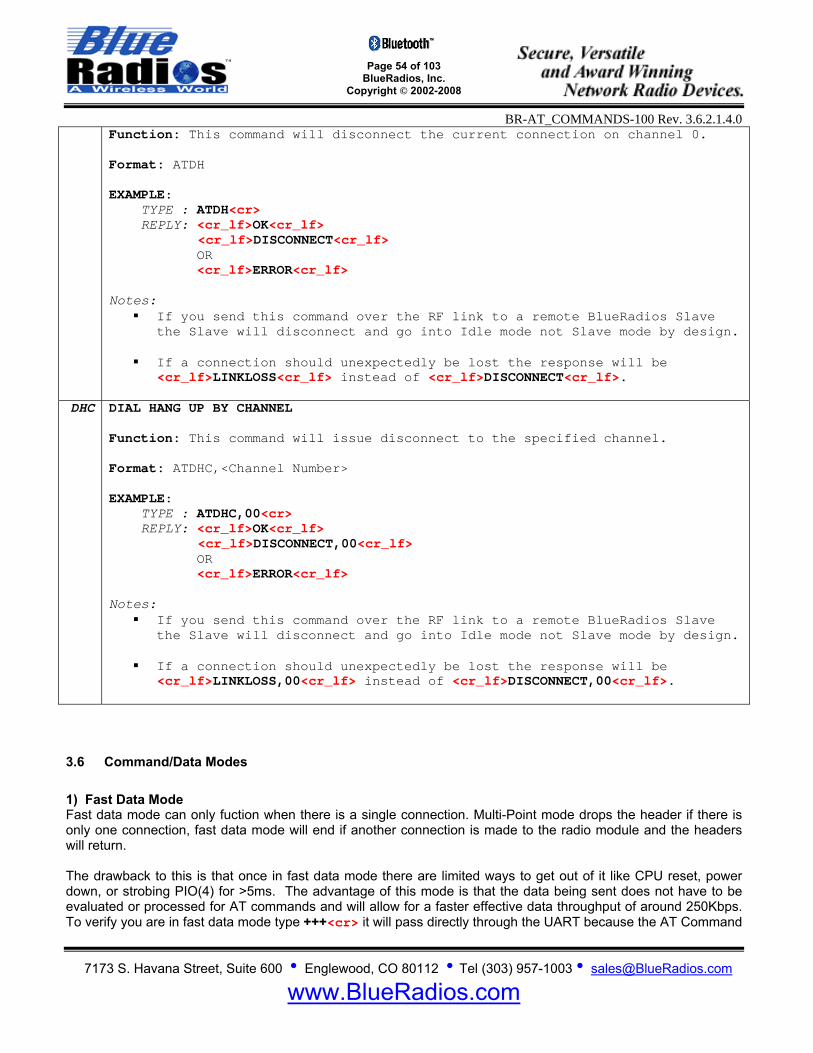
Page 54 of 103
BlueRadios, Inc. Copyright © 2002-2008
BR-AT_COMMANDS-100 Rev. 3.6.2.1.4.0
7173 S. Havana Street, Suite 600 • Englewood, CO 80112 • Tel (303) 957-1003 • [email protected]
www.BlueRadios.com
Function: This command will disconnect the current connection on channel 0. Format: ATDH EXAMPLE: TYPE : ATDH<cr> REPLY: <cr_lf>OK<cr_lf>
<cr_lf>DISCONNECT<cr_lf> OR <cr_lf>ERROR<cr_lf>
Notes:
If you send this command over the RF link to a remote BlueRadios Slave the Slave will disconnect and go into Idle mode not Slave mode by design.
If a connection should unexpectedly be lost the response will be
<cr_lf>LINKLOSS<cr_lf> instead of <cr_lf>DISCONNECT<cr_lf>.
DHC DIAL HANG UP BY CHANNEL Function: This command will issue disconnect to the specified channel. Format: ATDHC,<Channel Number> EXAMPLE: TYPE : ATDHC,00<cr> REPLY: <cr_lf>OK<cr_lf>
<cr_lf>DISCONNECT,00<cr_lf> OR <cr_lf>ERROR<cr_lf>
Notes:
If you send this command over the RF link to a remote BlueRadios Slave the Slave will disconnect and go into Idle mode not Slave mode by design.
If a connection should unexpectedly be lost the response will be
<cr_lf>LINKLOSS,00<cr_lf> instead of <cr_lf>DISCONNECT,00<cr_lf>.
3.6 Command/Data Modes 1) Fast Data Mode Fast data mode can only fuction when there is a single connection. Multi-Point mode drops the header if there is only one connection, fast data mode will end if another connection is made to the radio module and the headers will return. The drawback to this is that once in fast data mode there are limited ways to get out of it like CPU reset, power down, or strobing PIO(4) for >5ms. The advantage of this mode is that the data being sent does not have to be evaluated or processed for AT commands and will allow for a faster effective data throughput of around 250Kbps. To verify you are in fast data mode type +++<cr> it will pass directly through the UART because the AT Command

Page 55 of 103
BlueRadios, Inc. Copyright © 2002-2008
BR-AT_COMMANDS-100 Rev. 3.6.2.1.4.0
7173 S. Havana Street, Suite 600 • Englewood, CO 80112 • Tel (303) 957-1003 • [email protected]
www.BlueRadios.com
parser is off. Else the +++<cr> will be accepted because the AT Command parser is still on and returns “OK”. On the previous 4Mbit legacy modules the escape characters was fixed and set to “ATMC”, is no longer implemented. 2) Command/Data Mode The Command Mode or Data Mode will slow down the throughput when the radio looks for the AT commands. One way to allow minimal overhead transmission burden is to perform all configuration commands, and then place the radio into the fast data mode. Note: Byte Gaps and Data Latency – The way Bluetooth is designed and operates random byte gaps of 5 msec to 20 ms are common. Packet size will vary from transmission to transmission. The faster the UART speed the smaller the byte gap delay. Effective data payload throughput in fast data mode is approximately 250Kbps and 35Kbps in regular data mode when the AT parser looks at each character for ASCII valid command scripts in the data stream. The radio RX has very limited buffering so if you do not use hardware flow control and are transmitting further distances you will quickly overflow the buffer because of RF retransmissions, etc. When a Bluetooth connection is made the radio modem goes into regular data mode per the power-up factory default settings. This enables the user to remotely configure the radio settings via a remote RF Bluetooth connection. Basically you can setup the radio so no commands are required to be sent from the embedded side of the radios UART. This will prevent any software embedded firmware development or testing for legacy systems. +++ PUT RADIO INTO COMMAND MODE
Function: This sequence is used to force the radio into command mode state. If the Radio has been placed in Fast Data Mode this command will have no affect and the typed command will be treated as data. When using this command allow at least 100ms delay before sending the next AT command. Format: +++ Return Parameters: If successful an “OK” is returned, or nothing will be returned if already in command mode or fast data mode. EXAMPLE: TYPE : +++<cr> REPLY: <cr_lf>OK<cr_lf> Note: This command is only required if the module is RF CONNECTED, it has not effect if the module is not connected or if it is connected in Fast Data Mode.
SESC SET COMMAND MODE ESCAPE CHARACTER Function: Sets the radio’s escape character, used to put the radio into command mode. Format: ATSESC,<ASCII Value> Parameter:
ASCII Value: Integer value of a non extended ACII character
Factory Default: 43 = “+”
Page 56 of 103
BlueRadios, Inc. Copyright © 2002-2008
BR-AT_COMMANDS-100 Rev. 3.6.2.1.4.0
7173 S. Havana Street, Suite 600 • Englewood, CO 80112 • Tel (303) 957-1003 • [email protected]
www.BlueRadios.com
EXAMPLE: TYPE : ATSESC,43<cr> REPLY: <cr_lf>OK<cr_lf> OR <cr_lf>ERROR<cr_lf>
MD PUT RADIO INTO DATA MODE Function: Forces the radio into Data Mode. In order for this to have an effect the Radio has to be CONNECTED. Format: ATMD Return Parameters: If successful an “OK” is returned, or nothing will be returned if already in data or fast data mode, and connected. A “NO CARRIER” occurs when the Bluetooth connection has been lost. EXAMPLE: TYPE : ATMD<cr> REPLY: <cr_lf>OK<cr_lf> OR <cr_lf>NO CARRIER<cr_lf>
MF PUT RADIO INTO FAST DATA MODE Function: Forces the radio into Fast Data Mode on channel 00 only. Once in Fast Data Mode all commands are treated as data. Ways to get out of this mode are to reset power on the radio, or strobe PIO(4) while connected. Format: ATMF Return Parameters: If successful an “OK” is returned, or nothing will be returned if already in data or fast data mode, and connected. A “NO CARRIER” occurs when the Bluetooth connection has been lost. EXAMPLE: TYPE : ATMF<cr> REPLY: <cr_lf>OK<cr_lf> OR <cr_lf>ERROR<cr_lf> OR <cr_lf>NO CARRIER<cr_lf> Note: StrobePIO(4) >5ms to take radio out of fast data into command mode and maintain the Bluetooth RF connection. If not RF connected will place radio in command mode.
Page 57 of 103
BlueRadios, Inc. Copyright © 2002-2008
BR-AT_COMMANDS-100 Rev. 3.6.2.1.4.0
7173 S. Havana Street, Suite 600 • Englewood, CO 80112 • Tel (303) 957-1003 • [email protected]
www.BlueRadios.com
3.7 Utilities
3.7.1 Cancel Command UCL CANCEL
Function: The UCL command tells the radio to cancel inquiry or connect requests commands and then places the radio in Idle Mode. This command can come in handy for a quick exit from commands like inquiry mode if there are no devices in the area and you do not want to wait for an automatic timeout. You can not issue a cancel command while RF connected. This command can also be used to break out of the auto-master connect mode. If executed while connected in this mode, the radio will disconnect and enter idle mode instead of attempting to connect again. Format: ATUCL EXAMPLE: TYPE : ATUCL<cr> REPLY: <cr_lf>OK<cr_lf> OR <cr_lf>ERROR<cr_lf>
3.7.2 Pairing
PAIR PAIR RADIOS Function: This command tells the radio in Master mode to pair to a specific Bluetooth address. Format: ATPAIR,<BT Address> Parameters:
BT Address: Bluetooth Address, 12 hex characters MAX EXAMPLE: TYPE : ATPAIR,00A0961F008F<cr> REPLY: <cr_lf>OK<cr_lf> <cr_lf>PAIRED,123456789012<cr_lf> OR <cr_lf>ERROR<cr_lf> OR <cr_lf>PAIRED,FAILED<cr_lf> Read Using: ATSI,19
Notes:
The pairing timeout is 30 seconds.

Page 58 of 103
BlueRadios, Inc. Copyright © 2002-2008
BR-AT_COMMANDS-100 Rev. 3.6.2.1.4.0
7173 S. Havana Street, Suite 600 • Englewood, CO 80112 • Tel (303) 957-1003 • [email protected]
www.BlueRadios.com
The radio needs to be in idle mode prior to pairing. Security PINs are exchanged and must be equal for pairing to complete.
The timeout for this command is controlled by the master connect
timeout in ATSW28.
UPAIR UNPAIR BY INDEX
Function: The command tells the radio to unpair from the Bluetooth address stored in index locations 00, 01, 02, and 03. Format: ATUPAIR,<Index> Parameters:
Index: Index location 00, 01, 02 or 03 EXAMPLE: TYPE : ATUPAIR,00<cr> REPLY: <cr_lf>OK<cr_lf> OR <cr_lf>ERROR<cr_lf> Notes:
Use the command ATLAST to view the stored address after pairing. Pairing is not the same as a connection, so you will not see inquiry
or connectection indication. Can be in Master, Slave, or Idle mode to unpair. Will need to reset or cycle power to clear paired address.
UPAIRB UNPAIR BY BLUETOOTH ADDRESS
Function: This command tells the radio to unpair from the specified Bluetooth address. Format: ATUPAIRB,<BT Address> Parameters:
BT Address: Bluetooth Address, 12 hex characters MAX EXAMPLE: TYPE : ATUPAIR,123456789012<cr> REPLY: <cr_lf>OK<cr_lf> OR <cr_lf>ERROR<cr_lf>
CPAIR CLEAR ALL PAIRED DEVICES Function: This command tells the radio to unpair from all paired devices. Format: ATUPAIRC
Page 59 of 103
BlueRadios, Inc. Copyright © 2002-2008
BR-AT_COMMANDS-100 Rev. 3.6.2.1.4.0
7173 S. Havana Street, Suite 600 • Englewood, CO 80112 • Tel (303) 957-1003 • [email protected]
www.BlueRadios.com
EXAMPLE: TYPE : ATCPAIR<cr> REPLY: <cr_lf>OK<cr_lf>
3.7.3 Sniff and Park (Connected Slave) Park Suppoted in Point-to-Point mode only!
Low Power Modes Using Sniff Sniff mode is another power conservation method utilized by Bluetooth. By default, Sniff mode is disabled, and the radio is active continuously when connected (about 25-30ma). In Sniff mode, the radio wakes up at specific intervals, and sleeps in very low power mode (around 2ma) otherwise. The power savings can be quite dramatic if data is sent infrequently. However if data is constantly transmitted there is no power saving benefit to use Sniff. Example interval timers: 0x0020 = 20ms. (32 decimal * .625 = 20). 0x0050 = 50ms, 0x00A0 = 100ms, 0x0190 = ¼ second, 0x0320 = ½ second, 0x0640 = 1 second. Sniff mode only pertains to an active connection. When a connection is made, both master and slave must support Sniff mode, and agree to the Sniff window, otherwise the radio will stay in full active on mode. Note: the maximum allowed Sniff interval is about 20 seconds = 0x7FFF sniff word setting. Bluetooth connections are master/slave in nature. A master sends packets and a slave has to acknowledge that packet in the next timeslot. Timeslots in Bluetooth are 625 microseconds wide. This implies that a master will always know when packets will be sent and received, which further means it is able to optimize power usage by switching on power hungry circuitry only when needed.
A slave on the other hand does NOT have prior knowledge of when a packet will be received and has to assume that a packet will be received from a master on every receive slot. This means that it has to leave it’s receiving circuitry on for most of the receive slot duration. The result of this is high power consumption where a slave with no data transmission still consumes around 5mA.
This problem was identified very early in the evolution of Bluetooth (especially since headsets spend all their time as a slave in a Bluetooth connection) and it was solved by having a mode called Sniff, with appropriate lower layer negotiating protocol.
Sniff mode during connection is basically an agreement between the slave and its master of which data packets will only be exchanged for N timeslots every M slots. The slave can then assume that it will never be contacted during N-M slots, and so can switch its power hungry circuitry off. The specification goes further by also specifying a third parameter called ‘timeout’ (T) which specifies ‘extra’ timeslots that the slave will agree to listen for after receiving a valid data packet. Put another way, if a data packet is received by the slave, then it knows that it MUST carry on listening for at least T more slots. If within that T slot time period another data packet is received, then the timer is restarted. This mechanism ensures low power consumption when there is no data transfer – at the expense of latency. When there is a lot of data to be transferred, it acts as if sniff mode were not enabled.
It is stated above that during sniff mode, a slave listens for N slots every M slots. The Bluetooth specification states that a master can have up to 7 slaves attached to it with all slaves having requested varying sniff parameters. It may therefore be impossible to guarantee that each slave gets the M parameter it requested. In

Page 60 of 103
BlueRadios, Inc. Copyright © 2002-2008
BR-AT_COMMANDS-100 Rev. 3.6.2.1.4.0
7173 S. Havana Street, Suite 600 • Englewood, CO 80112 • Tel (303) 957-1003 • [email protected]
www.BlueRadios.com
light of this, the protocol for enabling sniff mode specifies that a requesting peer specify the M parameter as a minimum and maximum value. This will allow the master to interleave the sniff modes for all slaves attached. SNIFF ENABLE SNIFF
Function: Manually enables sniff mode for Slave device connected in time slots. Format: ATSNIFF,<Max Interval>,<Min Interval>,<Attempt>,<Timeout> Parameters:
Max Interval: Integer Value Time [ms] = Max Interval * 0.625ms Min Interval: Integer Value Time [ms] = Min Interval * 0.625ms Attempt: Integer Value Time [ms] = Attempt * 0.625ms Timeout: Integer Value Time [ms] = Timeout * 0.625ms
EXAMPLE: TYPE : ATSNIFF,1600,160,10,160<cr> REPLY: <cr_lf>OK<cr_lf> OR <cr_lf>NO CARRIER<cr_lf> Notes:
Manually enable sniff results in an always connected slave using only 2mA average current when no data is sent. Parameters are lost after connection is dropped.
The radio will exit sniff mode once the connection is terminated,
ATSNIFF must be executed again upon establishing a new connection in order to start sniff mode again.
SSNIFF ENABLE AUTO SNIFF
Function: Stores sniff parameters permanently in flash and auto starts sniff mode after a connection is established. Format: ATSSNIFF,<Max Interval>,<Min Interval>,<Attempt>,<Timeout> Parameters:
Max Interval: Integer Value Time [ms] = Max Interval * 0.625ms Min Interval: Integer Value Time [ms] = Min Interval * 0.625ms Attempt: Integer Value
Page 61 of 103
BlueRadios, Inc. Copyright © 2002-2008
BR-AT_COMMANDS-100 Rev. 3.6.2.1.4.0
7173 S. Havana Street, Suite 600 • Englewood, CO 80112 • Tel (303) 957-1003 • [email protected]
www.BlueRadios.com
Time [ms] = Attempt * 0.625ms Timeout: Integer Value Time [ms] = Timeout * 0.625ms
EXAMPLE: TYPE : ATSSNIFF,1600,160,10,160<cr> REPLY: <cr_lf>OK<cr_lf> OR <cr_lf>ERROR<cr_lf> Read Using: ATSI,17
CSNIFF CLEAR SNIFF Function: Clears stored sniff parameters. Format: ATCSNIFF EXAMPLE: TYPE : ATCSNIFF<cr> REPLY: <cr_lf>OK<cr_lf> OR <cr_lf>ERROR<cr_lf>
XSNIFF EXIT SNIFF Function: Tells the radio to exit and stop “sniffing” RF signals. Format: ATXSNIFF EXAMPLE: TYPE : ATXSNIFF<cr> REPLY: <cr_lf>OK<cr_lf> OR <cr_lf>NO CARRIER<cr_lf>
PARK ENABLE PARK Function: Manually enables park mode for device connected in time slots. Format: ATPARK,<Max Interval>,<Min Interval> Parameters:
Max Interval: Integer Value Time [ms] = Max Interval * 0.625ms Min Interval: Integer Value Time [ms] = Min Interval * 0.625ms
EXAMPLE: TYPE : ATPARK,1000,11<cr> REPLY: <cr_lf>OK<cr_lf> OR
Page 62 of 103
BlueRadios, Inc. Copyright © 2002-2008
BR-AT_COMMANDS-100 Rev. 3.6.2.1.4.0
7173 S. Havana Street, Suite 600 • Englewood, CO 80112 • Tel (303) 957-1003 • [email protected]
www.BlueRadios.com
<cr_lf>NO CARRIER<cr_lf> Notes:
Allow 7 seconds for the slave to drop its average current draw from 45mA to 3mA and go into PARK. Any UART traffic will cause the Slave radio go back to full operation within 5msec of the first character for 7 seconds before going back into PARK mode without subsequent data. The Slave will remain connected to the Master because the BlueRadios Module only supports one connection.
Both units are required to support park. Park request is sent from
both Master and Slave to go into affect only during an active Bluetooth connection. The order does not matter.
XPARK EXIT PARK
Function: Tells the radio to exit the park mode. Format: ATXPARK EXAMPLE: TYPE : ATXPARK<cr> REPLY: <cr_lf>OK<cr_lf> OR <cr_lf>NO CARRIER<cr_lf> Note: Unit will immediately exit park.
3.7.4 RSSI and Link Quality Golden Receive Power Range The lower threshold level of the Golden Receive Power Range corresponds to a receive power between -56 dBm and 6 dB above the actual sensitivity of the receiver. The upper threshold level is 20 dB above the lower threshold level to an accuracy of +/-6 dB.
RSSI GET RSSI VALUE Function: This command is used to obtain the RSSI value for an open connection on channel 0. This is a parameter associated with the ACL connection to a peer device. Format: ATRSSI Return Parameters: <RSSI Value>
RSSI Value is in hex, typically from -10 to +31 in integer dB value.
EXAMPLE: TYPE : ATRSSI<cr> REPLY: <cr_lf>OK<cr_lf> <cr_lf>+00<cr_lf>
Page 63 of 103
BlueRadios, Inc. Copyright © 2002-2008
BR-AT_COMMANDS-100 Rev. 3.6.2.1.4.0
7173 S. Havana Street, Suite 600 • Englewood, CO 80112 • Tel (303) 957-1003 • [email protected]
www.BlueRadios.com
OR <cr_lf>ERROR<cr_lf> Notes:
The RSSI value will be +00 if the signal is within the Golden Range.
The Golden Range min and max value is 1 and 12 respectively for the modules.
This value is the difference between the measured Received Signal
Strength Indication (RSSI) and the limits of the Golden Receive Power Range (see below for definition). Any positive RSSI value returned by the Host side indicates how many dB the RSSI is above the upper limit. Any negative value indicates how many dB the RSSI is below the lower limit. A value of zero indicates that the RSSI is inside the Golden Receive Power Range.
How accurate the dB values will be depends on the Bluetooth hardware.
The only requirements for the hardware are that the Bluetooth device is able to tell whether the RSSI is inside, above, or below the Golden Device Power Range.
RSSIC GET RSSI VALUE BY CHANNEL
Function: Gets the RSSI Value by channel number. Format: ATRSSIC,<Channel Number> Parameters:
Channel Number: 0, 1, 2, 3 Return Parameters: <RSSI Value>
RSSI Value is in hex, typically from -10 to +31 in integer dB value. EXAMPLE: REPLY: <cr_lf>OK<cr_lf> <cr_lf>+00<cr_lf> OR <cr_lf>ERROR<cr_lf>
LQ GET LINK QUALITY Function: Gets the link quality of the current connection. Format: ATLQ Return Parameters: <Link Quality>
Hex value from 0 to 255 decimal which is the measure of Bit Error Rate (BER)
EXAMPLE: TYPE : ATLQ<cr> REPLY: <cr_lf>OK<cr_lf>
Page 64 of 103
BlueRadios, Inc. Copyright © 2002-2008
BR-AT_COMMANDS-100 Rev. 3.6.2.1.4.0
7173 S. Havana Street, Suite 600 • Englewood, CO 80112 • Tel (303) 957-1003 • [email protected]
www.BlueRadios.com
<cr_lf>FF<cr_lf> OR <cr_lf>ERROR<cr_lf> Note: Link Quality is a Hex value from 0-255, which represents the quality of the link between two Bluetooth devices. The higher the value, the better the link quality is. Each Bluetooth module vendor will determine how to measure the link quality. In the case for CSR, this value is a measure of BER.
LQC GET LINK QUALITY BY CHANNEL Function: Gets the Link Quality by channel number. Format: ATLQC,<Channel Number> Parameters:
Channel Number: 0, 1, 2, 3 Return Parameters: <RSSI Value>
Hex value from 0 to 255 decimal which is the measure of Bit Error Rate (BER)
EXAMPLE: TYPE : ATLQ,1<cr> REPLY: <cr_lf>OK<cr_lf> <cr_lf>FF<cr_lf> OR <cr_lf>ERROR<cr_lf>
3.7.5 Audio (SCO) PCM Interface DSCO DIAL SCO
Function: Tells the radio to dial and connect the audio channel. Format: ATDSCO EXAMPLE: TYPE : ATDSCO<cr> REPLY: <cr_lf>OK<cr_lf> <cr_lf>SCO CONNECT<cr_lf> OR <cr_lf>OK<cr_lf> <cr_lf>SCO FAILED<cr_lf> OR <cr_lf>NO CARRIER<cr_lf>
Page 65 of 103
BlueRadios, Inc. Copyright © 2002-2008
BR-AT_COMMANDS-100 Rev. 3.6.2.1.4.0
7173 S. Havana Street, Suite 600 • Englewood, CO 80112 • Tel (303) 957-1003 • [email protected]
www.BlueRadios.com
DESCO DIAL ESCO Function: Tells the radio to dial and connect the audio channel. Format: ATDESCO EXAMPLE: TYPE : ATDESCO<cr> REPLY: <cr_lf>OK<cr_lf> <cr_lf>ESCO CONNECT<cr_lf> OR <cr_lf>OK<cr_lf> <cr_lf>ESCO FAILED<cr_lf> OR <cr_lf>ESCO REJECTED<cr_lf> OR <cr_lf>NO CARRIER<cr_lf> Note: When the desired device is known to not support eSCO use the ATDSCO command above.
DHSCO DIAL HANG UP SCO Function: Tells the radio to disconnect the audio channel. Format: ATDHSCO EXAMPLE: TYPE : ATDHSCO<cr> REPLY: <cr_lf>OK<cr_lf> <cr_lf>SCO DISCONNECT<cr_lf> OR <cr_lf>NO CARRIER<cr_lf>
3.7.6 Max TX Power SPF SET MAX TX POWER LEVEL
Format: ATSPF,<Power Level>,<Sign> Parameters:
Power Level: Integer from 0 to 10 Sign: + or –
(Combined value of level and sign must be in the range of -5 to +10)
Typical BlueTooth Industry Values Depending On Device Class Type: - Class 1 = 0dBm to +10dBm - Class 2 = -8dBm to +4dBm - Class 3 = 0dBm Max
BlueRadios Power Table Values:
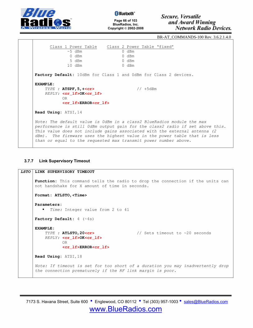
Page 66 of 103
BlueRadios, Inc. Copyright © 2002-2008
BR-AT_COMMANDS-100 Rev. 3.6.2.1.4.0
7173 S. Havana Street, Suite 600 • Englewood, CO 80112 • Tel (303) 957-1003 • [email protected]
www.BlueRadios.com
Class 1 Power Table Class 2 Power Table “fixed”
-5 dBm 0 dBm 0 dBm 0 dBm 5 dBm 0 dBm 10 dBm 0 dBm
Factory Default: 10dBm for Class 1 and 0dBm for Class 2 devices. EXAMPLE: TYPE : ATSPF,5,+<cr> // +5dBm REPLY: <cr_lf>OK<cr_lf> OR <cr_lf>ERROR<cr_lf> Read Using: ATSI,14 Note: The default value is 0dBm in a class2 BlueRadios module the max performance is still 0dBm output gain for the class2 radio if set above this. This value does not include gains associated with the external antenna (2 dBm). The firmware uses the highest value in the power table that is less than or equal to the requested max transmit power number above.
3.7.7 Link Supervisory Timeout
LSTO LINK SUPERVISORY TIMEOUT Function: This command tells the radio to drop the connection if the units can not handshake for X amount of time in seconds. Format: ATLSTO,<Time> Parameters:
Time: Integer value from 2 to 41
Factory Default: 4 (~4s) EXAMPLE: TYPE : ATLSTO,20<cr> // Sets timeout to ~20 seconds REPLY: <cr_lf>OK<cr_lf> OR <cr_lf>ERROR<cr_lf> Read Using: ATSI,18 Note: If timeout is set for too short of a duration you may inadvertently drop the connection prematurely if the RF link margin is poor.
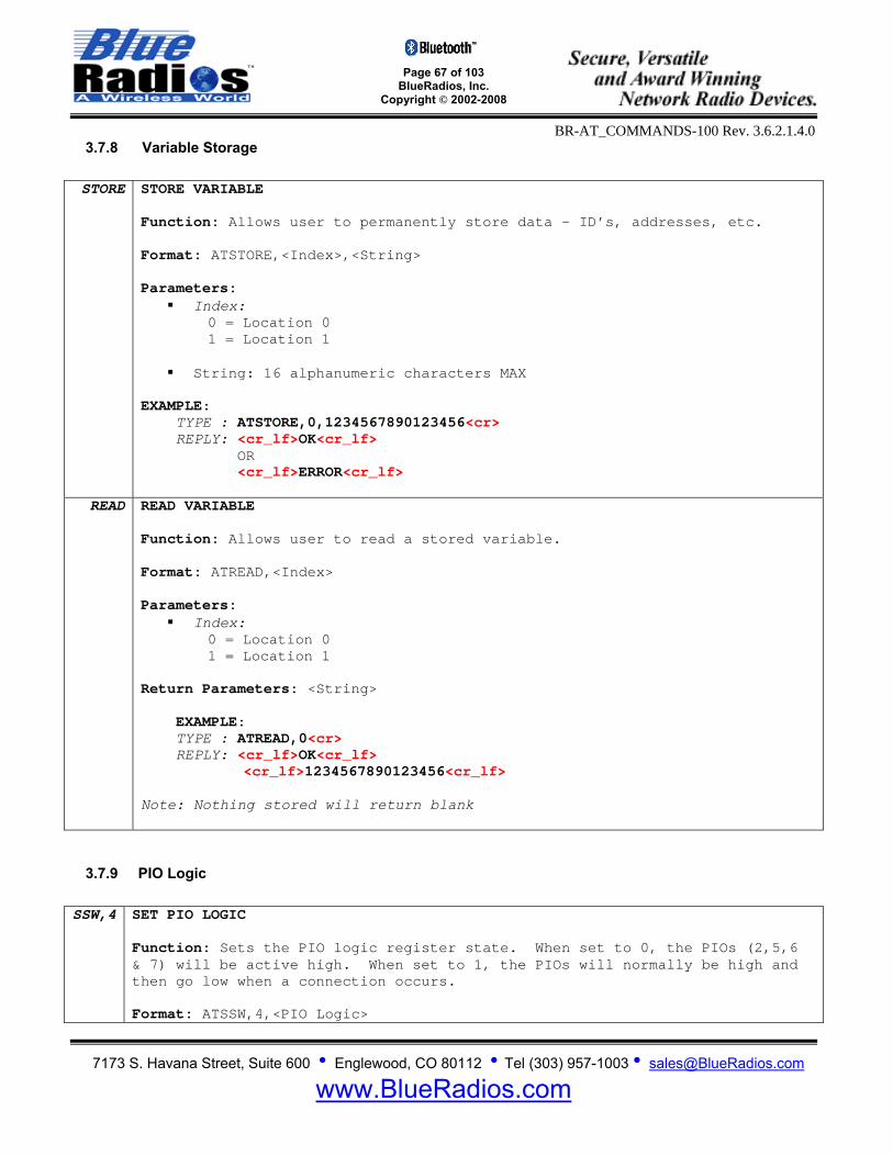
Page 67 of 103
BlueRadios, Inc. Copyright © 2002-2008
BR-AT_COMMANDS-100 Rev. 3.6.2.1.4.0
7173 S. Havana Street, Suite 600 • Englewood, CO 80112 • Tel (303) 957-1003 • [email protected]
www.BlueRadios.com
3.7.8 Variable Storage STORE STORE VARIABLE
Function: Allows user to permanently store data – ID’s, addresses, etc. Format: ATSTORE,<Index>,<String> Parameters:
Index: 0 = Location 0 1 = Location 1
String: 16 alphanumeric characters MAX
EXAMPLE: TYPE : ATSTORE,0,1234567890123456<cr> REPLY: <cr_lf>OK<cr_lf> OR <cr_lf>ERROR<cr_lf>
READ READ VARIABLE Function: Allows user to read a stored variable. Format: ATREAD,<Index> Parameters:
Index: 0 = Location 0 1 = Location 1
Return Parameters: <String> EXAMPLE: TYPE : ATREAD,0<cr> REPLY: <cr_lf>OK<cr_lf>
<cr_lf>1234567890123456<cr_lf>
Note: Nothing stored will return blank
3.7.9 PIO Logic SSW,4 SET PIO LOGIC
Function: Sets the PIO logic register state. When set to 0, the PIOs (2,5,6 & 7) will be active high. When set to 1, the PIOs will normally be high and then go low when a connection occurs. Format: ATSSW,4,<PIO Logic>
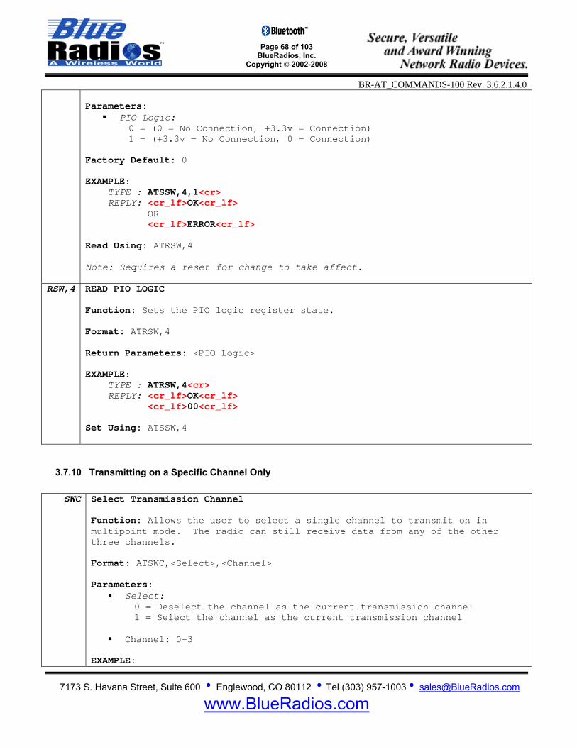
Page 68 of 103
BlueRadios, Inc. Copyright © 2002-2008
BR-AT_COMMANDS-100 Rev. 3.6.2.1.4.0
7173 S. Havana Street, Suite 600 • Englewood, CO 80112 • Tel (303) 957-1003 • [email protected]
www.BlueRadios.com
Parameters:
PIO Logic: 0 = (0 = No Connection, +3.3v = Connection) 1 = (+3.3v = No Connection, 0 = Connection)
Factory Default: 0
EXAMPLE: TYPE : ATSSW,4,1<cr> REPLY: <cr_lf>OK<cr_lf> OR <cr_lf>ERROR<cr_lf> Read Using: ATRSW,4 Note: Requires a reset for change to take affect.
RSW,4 READ PIO LOGIC Function: Sets the PIO logic register state. Format: ATRSW,4 Return Parameters: <PIO Logic> EXAMPLE: TYPE : ATRSW,4<cr> REPLY: <cr_lf>OK<cr_lf> <cr_lf>00<cr_lf> Set Using: ATSSW,4
3.7.10 Transmitting on a Specific Channel Only
SWC Select Transmission Channel Function: Allows the user to select a single channel to transmit on in multipoint mode. The radio can still receive data from any of the other three channels. Format: ATSWC,<Select>,<Channel> Parameters:
Select: 0 = Deselect the channel as the current transmission channel 1 = Select the channel as the current transmission channel
Channel: 0-3
EXAMPLE:

Page 69 of 103
BlueRadios, Inc. Copyright © 2002-2008
BR-AT_COMMANDS-100 Rev. 3.6.2.1.4.0
7173 S. Havana Street, Suite 600 • Englewood, CO 80112 • Tel (303) 957-1003 • [email protected]
www.BlueRadios.com
TYPE : ATSWC,1,0<cr> REPLY: <cr_lf>OK<cr_lf> OR <cr_lf>ERROR<cr_lf> Read Using: ATSI,21 Note: If the selected channel is disconnected the radio will default to transmitting on all channels.
3.7.11 Making the Radio Discoverable and Undiscoverable
SDIS Set Discoverable Function: Makes the radio discoverable and connectable. Format: ATSDIS EXAMPLE: TYPE : ATSDIS<cr> REPLY: <cr_lf>OK<cr_lf>
UDIS Set Undiscoverable Function: Makes the radio undiscoverable. Format: ATUDIS EXAMPLE: TYPE : ATUDIS<cr> REPLY: <cr_lf>OK<cr_lf> Note: This command is not stored and must be made each time the radio is powered up.

Page 70 of 103
BlueRadios, Inc. Copyright © 2002-2008
BR-AT_COMMANDS-100 Rev. 3.6.2.1.4.0
7173 S. Havana Street, Suite 600 • Englewood, CO 80112 • Tel (303) 957-1003 • [email protected]
www.BlueRadios.com
4 Using FTP and OPP Modes Using the radio in FTP and OPP modes is much different from any of the other available connection modes. Connections are not made using ATDM or ATDS and services are not configured using the ATSSNC command. Connection status must be obtained using ATSI22, as ATSI3 contains no information regarding FTP or OPP connections. In addition only one connection is allowed at a time, so multi-point mode will be disabled once the radio is in FTP or OPP mode. To use the radio as an FTP or OPP client simply use the ATDFTP or ATDOPP command to make a connection to a server. In order to use the radio as an FTP or OPP server the user must set the Power-Up Connection Mode parameter in ATSW25 to either 7 or 8. Following a reset the radio will only have one service exposed, which will either be an FTP or OPP server depending on the value set in ATSW25. Be aware that due to the extra overhead required to operate in FTP and OPP modes, the data throughput in these modes will be much lower. The radio will not operate in Data Mode or Fast Data Mode, so the comm parameter in ATSW25 will have no effect on the throughput. In FTP or OPP client mode the throughput will be approximately 30kbps if the radio is in idle mode prior to making a connection. If the radio is not in idle mode the client throughput will be approximately 15kbps. As an FTP or OPP server the maximum throughput will be approximately 1.4kbps.
4.1 FTP Client The following FTP (File Transfer Protocol) commands allow the radio to be used as an FTP client, enabling it to manipulate files on an FTP server. As the client, the radio will initiate the connection with the server, e.g. a PC, PDA, or cell phone. After making a connection the radio can browse the server’s Bluetooth exchange directory, as well as upload and download files to and from the server. Note: To achieve the maximum data throughput of 30kbps in FTP client mode execute an ATUCL command prior to making an FTP connection to put the radio in idle mode. If the radio is not in idle mode the data throughput will be approximately 15kbps.
4.1.1 FTP Connect/Disconnect DFTP DIAL FTP
Function: This command creates a connection to the OBEX File Transfer service on a remote radio. Once this command has been sent the radio will be unconnectable until the FTP connection is disconnected. Format: ATDFTP,<BT Address> Parameters:
BT Address: Bluetooth Address, 12 hex characters MAX
Return Parameters: <BT Address> EXAMPLE: TYPE : ATDFTP,123456789012<cr> REPLY: <cr_lf>OK<cr_lf> <cr_lf>FTP CONNECT,123456789012<cr_lf> OR <cr_lf>OK<cr_lf> <cr_lf>PAIRED,123456789012<cr_lf> // if security is enabled
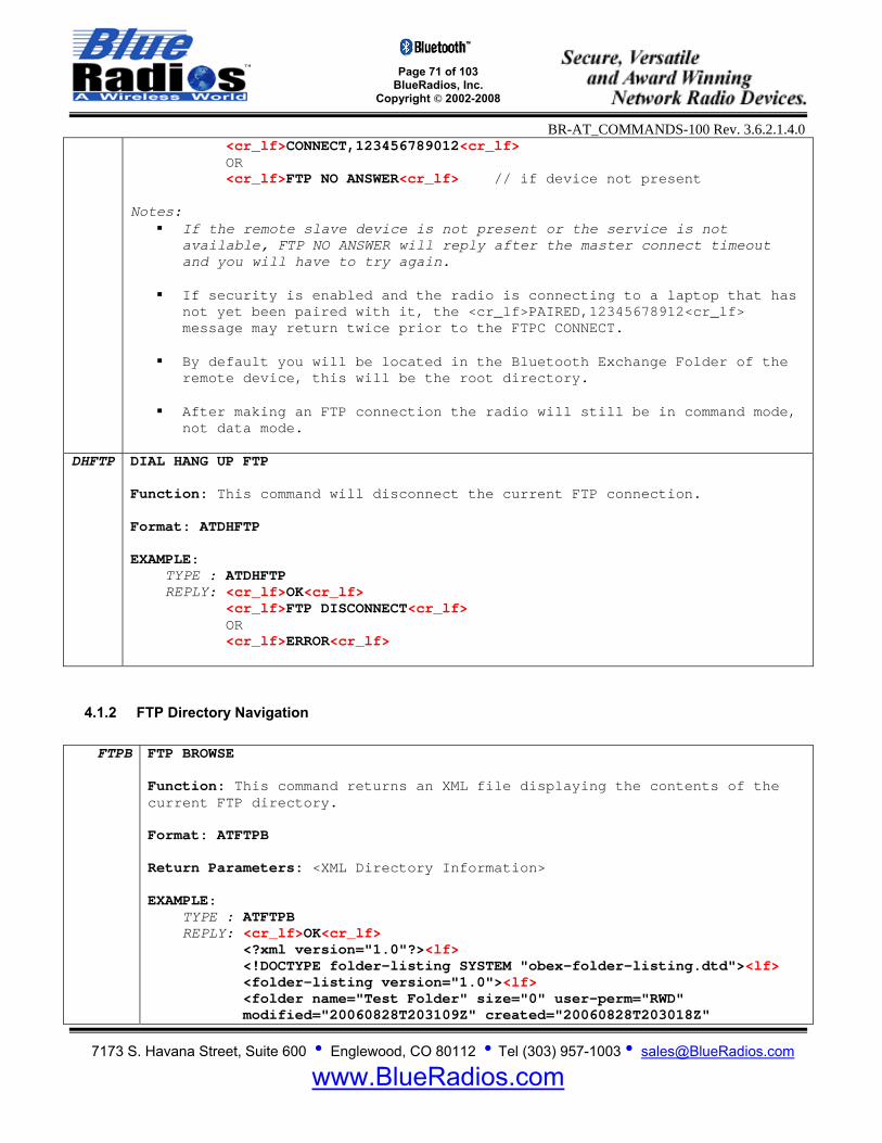
Page 71 of 103
BlueRadios, Inc. Copyright © 2002-2008
BR-AT_COMMANDS-100 Rev. 3.6.2.1.4.0
7173 S. Havana Street, Suite 600 • Englewood, CO 80112 • Tel (303) 957-1003 • [email protected]
www.BlueRadios.com
<cr_lf>CONNECT,123456789012<cr_lf> OR <cr_lf>FTP NO ANSWER<cr_lf> // if device not present Notes:
If the remote slave device is not present or the service is not available, FTP NO ANSWER will reply after the master connect timeout and you will have to try again.
If security is enabled and the radio is connecting to a laptop that has
not yet been paired with it, the <cr_lf>PAIRED,12345678912<cr_lf> message may return twice prior to the FTPC CONNECT.
By default you will be located in the Bluetooth Exchange Folder of the
remote device, this will be the root directory.
After making an FTP connection the radio will still be in command mode, not data mode.
DHFTP DIAL HANG UP FTP
Function: This command will disconnect the current FTP connection. Format: ATDHFTP EXAMPLE: TYPE : ATDHFTP REPLY: <cr_lf>OK<cr_lf> <cr_lf>FTP DISCONNECT<cr_lf> OR <cr_lf>ERROR<cr_lf>
4.1.2 FTP Directory Navigation
FTPB FTP BROWSE Function: This command returns an XML file displaying the contents of the current FTP directory. Format: ATFTPB
Return Parameters: <XML Directory Information> EXAMPLE: TYPE : ATFTPB REPLY: <cr_lf>OK<cr_lf> <?xml version="1.0"?><lf>
<!DOCTYPE folder-listing SYSTEM "obex-folder-listing.dtd"><lf> <folder-listing version="1.0"><lf> <folder name="Test Folder" size="0" user-perm="RWD" modified="20060828T203109Z" created="20060828T203018Z"
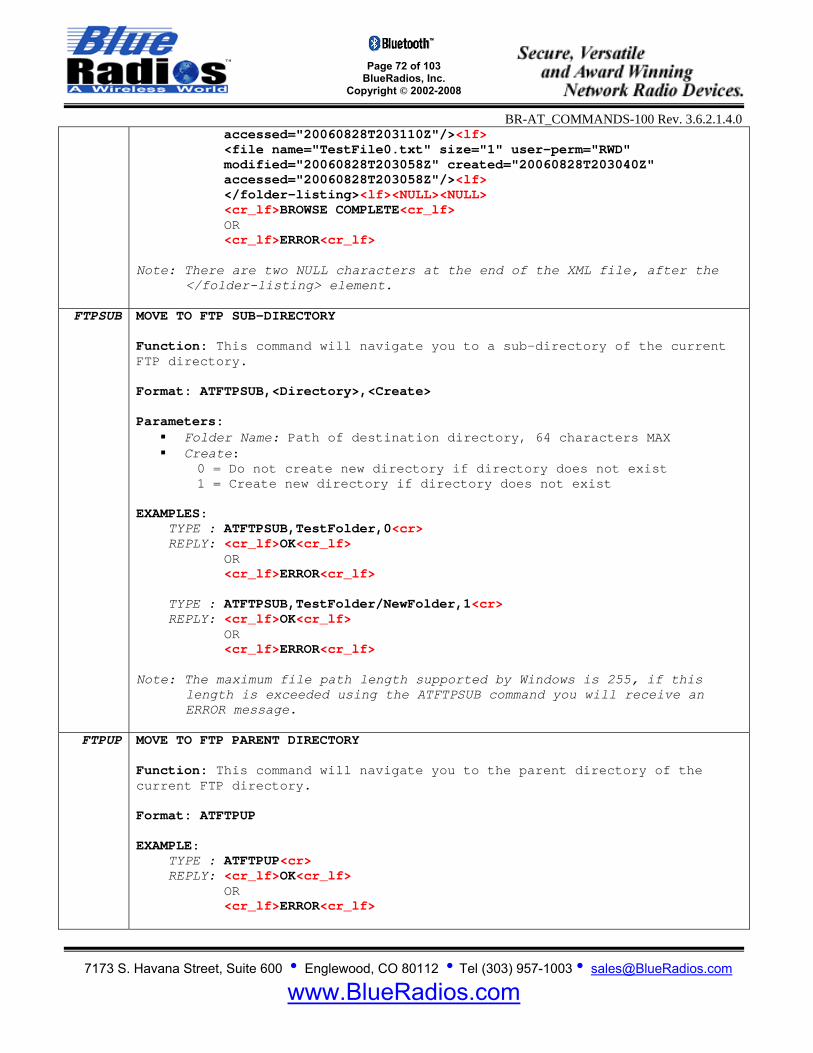
Page 72 of 103
BlueRadios, Inc. Copyright © 2002-2008
BR-AT_COMMANDS-100 Rev. 3.6.2.1.4.0
7173 S. Havana Street, Suite 600 • Englewood, CO 80112 • Tel (303) 957-1003 • [email protected]
www.BlueRadios.com
accessed="20060828T203110Z"/><lf> <file name="TestFile0.txt" size="1" user-perm="RWD" modified="20060828T203058Z" created="20060828T203040Z" accessed="20060828T203058Z"/><lf> </folder-listing><lf><NULL><NULL> <cr_lf>BROWSE COMPLETE<cr_lf> OR <cr_lf>ERROR<cr_lf> Note: There are two NULL characters at the end of the XML file, after the
</folder-listing> element.
FTPSUB MOVE TO FTP SUB-DIRECTORY Function: This command will navigate you to a sub-directory of the current FTP directory. Format: ATFTPSUB,<Directory>,<Create> Parameters:
Folder Name: Path of destination directory, 64 characters MAX Create:
0 = Do not create new directory if directory does not exist 1 = Create new directory if directory does not exist
EXAMPLES: TYPE : ATFTPSUB,TestFolder,0<cr> REPLY: <cr_lf>OK<cr_lf> OR <cr_lf>ERROR<cr_lf> TYPE : ATFTPSUB,TestFolder/NewFolder,1<cr> REPLY: <cr_lf>OK<cr_lf> OR <cr_lf>ERROR<cr_lf> Note: The maximum file path length supported by Windows is 255, if this
length is exceeded using the ATFTPSUB command you will receive an ERROR message.
FTPUP MOVE TO FTP PARENT DIRECTORY
Function: This command will navigate you to the parent directory of the current FTP directory. Format: ATFTPUP EXAMPLE: TYPE : ATFTPUP<cr> REPLY: <cr_lf>OK<cr_lf> OR <cr_lf>ERROR<cr_lf>
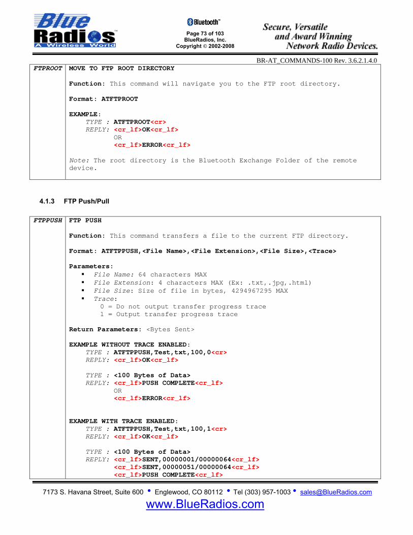
Page 73 of 103
BlueRadios, Inc. Copyright © 2002-2008
BR-AT_COMMANDS-100 Rev. 3.6.2.1.4.0
7173 S. Havana Street, Suite 600 • Englewood, CO 80112 • Tel (303) 957-1003 • [email protected]
www.BlueRadios.com
FTPROOT MOVE TO FTP ROOT DIRECTORY Function: This command will navigate you to the FTP root directory. Format: ATFTPROOT EXAMPLE: TYPE : ATFTPROOT<cr> REPLY: <cr_lf>OK<cr_lf> OR <cr_lf>ERROR<cr_lf> Note: The root directory is the Bluetooth Exchange Folder of the remote device.
4.1.3 FTP Push/Pull FTPPUSH FTP PUSH
Function: This command transfers a file to the current FTP directory. Format: ATFTPPUSH,<File Name>,<File Extension>,<File Size>,<Trace> Parameters:
File Name: 64 characters MAX File Extension: 4 characters MAX (Ex: .txt,.jpg,.html) File Size: Size of file in bytes, 4294967295 MAX Trace:
0 = Do not output transfer progress trace 1 = Output transfer progress trace
Return Parameters: <Bytes Sent> EXAMPLE WITHOUT TRACE ENABLED: TYPE : ATFTPPUSH,Test,txt,100,0<cr> REPLY: <cr_lf>OK<cr_lf> TYPE : <100 Bytes of Data> REPLY: <cr_lf>PUSH COMPLETE<cr_lf> OR <cr_lf>ERROR<cr_lf> EXAMPLE WITH TRACE ENABLED: TYPE : ATFTPPUSH,Test,txt,100,1<cr> REPLY: <cr_lf>OK<cr_lf> TYPE : <100 Bytes of Data> REPLY: <cr_lf>SENT,00000001/00000064<cr_lf> <cr_lf>SENT,00000051/00000064<cr_lf> <cr_lf>PUSH COMPLETE<cr_lf>
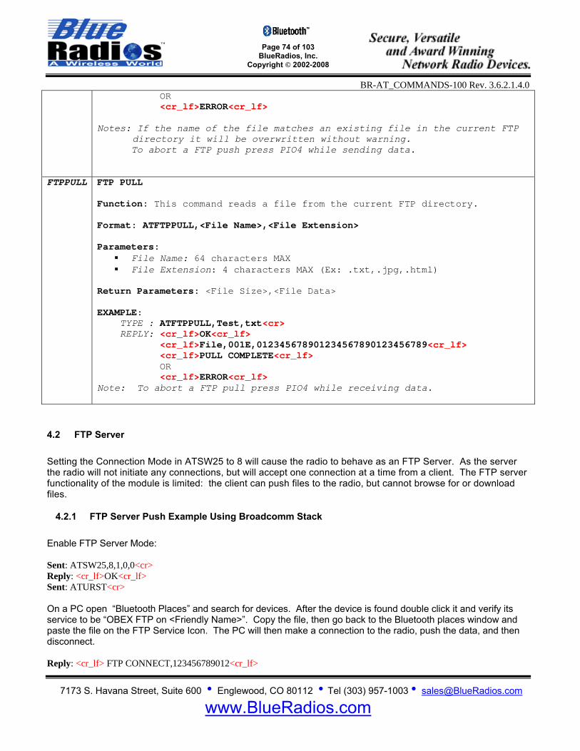
Page 74 of 103
BlueRadios, Inc. Copyright © 2002-2008
BR-AT_COMMANDS-100 Rev. 3.6.2.1.4.0
7173 S. Havana Street, Suite 600 • Englewood, CO 80112 • Tel (303) 957-1003 • [email protected]
www.BlueRadios.com
OR <cr_lf>ERROR<cr_lf> Notes: If the name of the file matches an existing file in the current FTP
directory it will be overwritten without warning. To abort a FTP push press PIO4 while sending data.
FTPPULL FTP PULL Function: This command reads a file from the current FTP directory. Format: ATFTPPULL,<File Name>,<File Extension> Parameters:
File Name: 64 characters MAX File Extension: 4 characters MAX (Ex: .txt,.jpg,.html)
Return Parameters: <File Size>,<File Data>
EXAMPLE: TYPE : ATFTPPULL,Test,txt<cr> REPLY: <cr_lf>OK<cr_lf> <cr_lf>File,001E,012345678901234567890123456789<cr_lf> <cr_lf>PULL COMPLETE<cr_lf> OR <cr_lf>ERROR<cr_lf> Note: To abort a FTP pull press PIO4 while receiving data.
4.2 FTP Server Setting the Connection Mode in ATSW25 to 8 will cause the radio to behave as an FTP Server. As the server the radio will not initiate any connections, but will accept one connection at a time from a client. The FTP server functionality of the module is limited: the client can push files to the radio, but cannot browse for or download files.
4.2.1 FTP Server Push Example Using Broadcomm Stack Enable FTP Server Mode: Sent: ATSW25,8,1,0,0<cr> Reply: <cr_lf>OK<cr_lf> Sent: ATURST<cr> On a PC open “Bluetooth Places” and search for devices. After the device is found double click it and verify its service to be “OBEX FTP on <Friendly Name>”. Copy the file, then go back to the Bluetooth places window and paste the file on the FTP Service Icon. The PC will then make a connection to the radio, push the data, and then disconnect. Reply: <cr_lf> FTP CONNECT,123456789012<cr_lf>
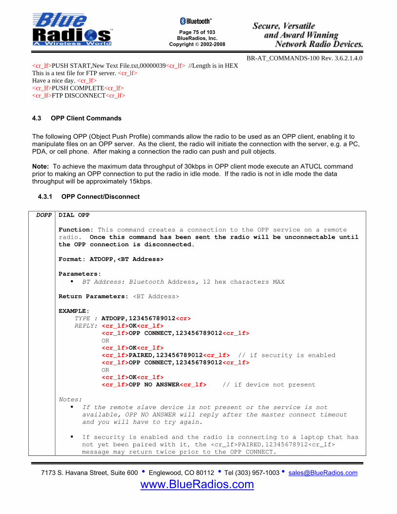
Page 75 of 103
BlueRadios, Inc. Copyright © 2002-2008
BR-AT_COMMANDS-100 Rev. 3.6.2.1.4.0
7173 S. Havana Street, Suite 600 • Englewood, CO 80112 • Tel (303) 957-1003 • [email protected]
www.BlueRadios.com
<cr_lf>PUSH START,New Text File.txt,00000039<cr_lf> //Length is in HEX This is a test file for FTP server. <cr_lf> Have a nice day. <cr_lf> <cr_lf>PUSH COMPLETE<cr_lf> <cr_lf>FTP DISCONNECT<cr_lf>
4.3 OPP Client Commands The following OPP (Object Push Profile) commands allow the radio to be used as an OPP client, enabling it to manipulate files on an OPP server. As the client, the radio will initiate the connection with the server, e.g. a PC, PDA, or cell phone. After making a connection the radio can push and pull objects. Note: To achieve the maximum data throughput of 30kbps in OPP client mode execute an ATUCL command prior to making an OPP connection to put the radio in idle mode. If the radio is not in idle mode the data throughput will be approximately 15kbps.
4.3.1 OPP Connect/Disconnect DOPP DIAL OPP
Function: This command creates a connection to the OPP service on a remote radio. Once this command has been sent the radio will be unconnectable until the OPP connection is disconnected. Format: ATDOPP,<BT Address> Parameters:
BT Address: Bluetooth Address, 12 hex characters MAX
Return Parameters: <BT Address> EXAMPLE: TYPE : ATDOPP,123456789012<cr> REPLY: <cr_lf>OK<cr_lf> <cr_lf>OPP CONNECT,123456789012<cr_lf> OR <cr_lf>OK<cr_lf> <cr_lf>PAIRED,123456789012<cr_lf> // if security is enabled <cr_lf>OPP CONNECT,123456789012<cr_lf> OR <cr_lf>OK<cr_lf> <cr_lf>OPP NO ANSWER<cr_lf> // if device not present Notes:
If the remote slave device is not present or the service is not available, OPP NO ANSWER will reply after the master connect timeout and you will have to try again.
If security is enabled and the radio is connecting to a laptop that has
not yet been paired with it, the <cr_lf>PAIRED,12345678912<cr_lf> message may return twice prior to the OPP CONNECT.
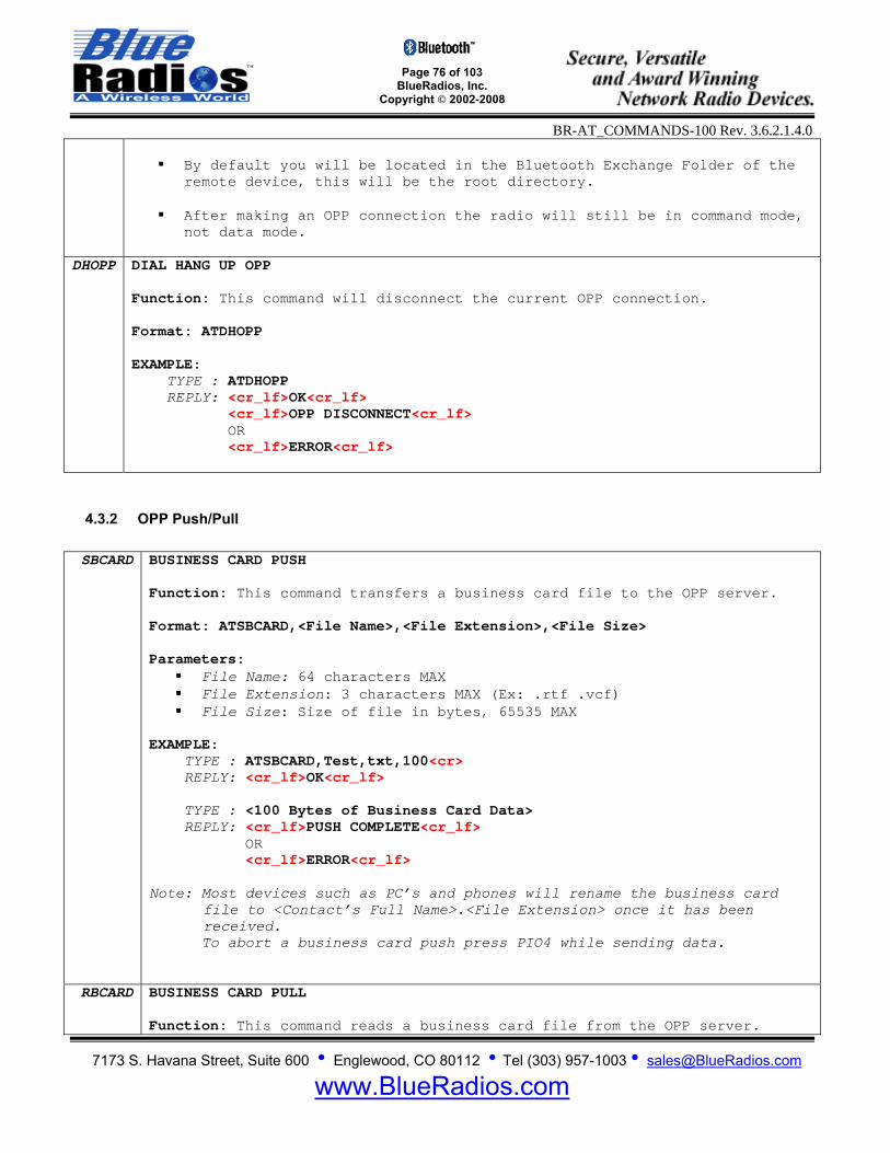
Page 76 of 103
BlueRadios, Inc. Copyright © 2002-2008
BR-AT_COMMANDS-100 Rev. 3.6.2.1.4.0
7173 S. Havana Street, Suite 600 • Englewood, CO 80112 • Tel (303) 957-1003 • [email protected]
www.BlueRadios.com
By default you will be located in the Bluetooth Exchange Folder of the
remote device, this will be the root directory.
After making an OPP connection the radio will still be in command mode, not data mode.
DHOPP DIAL HANG UP OPP
Function: This command will disconnect the current OPP connection. Format: ATDHOPP EXAMPLE: TYPE : ATDHOPP REPLY: <cr_lf>OK<cr_lf> <cr_lf>OPP DISCONNECT<cr_lf> OR <cr_lf>ERROR<cr_lf>
4.3.2 OPP Push/Pull SBCARD BUSINESS CARD PUSH
Function: This command transfers a business card file to the OPP server. Format: ATSBCARD,<File Name>,<File Extension>,<File Size> Parameters:
File Name: 64 characters MAX File Extension: 3 characters MAX (Ex: .rtf .vcf) File Size: Size of file in bytes, 65535 MAX
EXAMPLE: TYPE : ATSBCARD,Test,txt,100<cr> REPLY: <cr_lf>OK<cr_lf> TYPE : <100 Bytes of Business Card Data> REPLY: <cr_lf>PUSH COMPLETE<cr_lf> OR <cr_lf>ERROR<cr_lf> Note: Most devices such as PC’s and phones will rename the business card
file to <Contact’s Full Name>.<File Extension> once it has been received.
To abort a business card push press PIO4 while sending data.
RBCARD BUSINESS CARD PULL Function: This command reads a business card file from the OPP server.
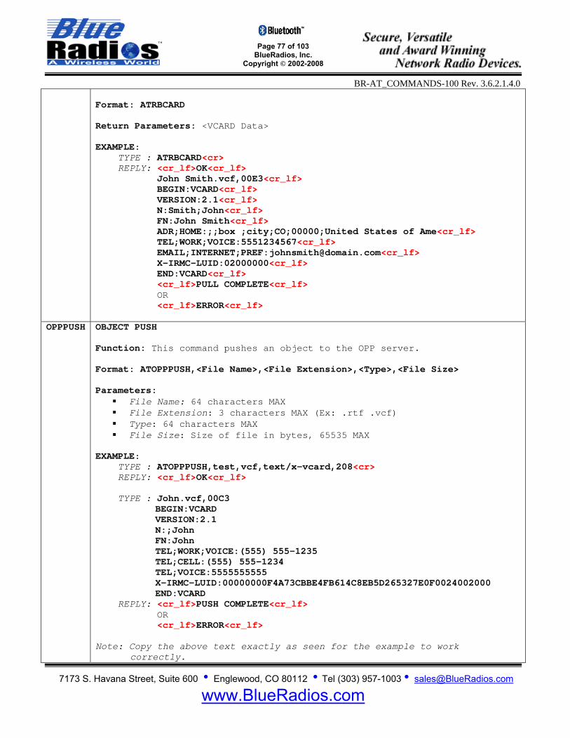
Page 77 of 103
BlueRadios, Inc. Copyright © 2002-2008
BR-AT_COMMANDS-100 Rev. 3.6.2.1.4.0
7173 S. Havana Street, Suite 600 • Englewood, CO 80112 • Tel (303) 957-1003 • [email protected]
www.BlueRadios.com
Format: ATRBCARD Return Parameters: <VCARD Data>
EXAMPLE: TYPE : ATRBCARD<cr> REPLY: <cr_lf>OK<cr_lf> John Smith.vcf,00E3<cr_lf> BEGIN:VCARD<cr_lf> VERSION:2.1<cr_lf> N:Smith;John<cr_lf> FN:John Smith<cr_lf> ADR;HOME:;;box ;city;CO;00000;United States of Ame<cr_lf> TEL;WORK;VOICE:5551234567<cr_lf> EMAIL;INTERNET;PREF:[email protected]<cr_lf> X-IRMC-LUID:02000000<cr_lf> END:VCARD<cr_lf> <cr_lf>PULL COMPLETE<cr_lf> OR <cr_lf>ERROR<cr_lf>
OPPPUSH OBJECT PUSH Function: This command pushes an object to the OPP server. Format: ATOPPPUSH,<File Name>,<File Extension>,<Type>,<File Size> Parameters:
File Name: 64 characters MAX File Extension: 3 characters MAX (Ex: .rtf .vcf) Type: 64 characters MAX File Size: Size of file in bytes, 65535 MAX
EXAMPLE: TYPE : ATOPPPUSH,test,vcf,text/x-vcard,208<cr> REPLY: <cr_lf>OK<cr_lf> TYPE : John.vcf,00C3
BEGIN:VCARD VERSION:2.1 N:;John FN:John TEL;WORK;VOICE:(555) 555-1235 TEL;CELL:(555) 555-1234 TEL;VOICE:5555555555 X-IRMC-LUID:00000000F4A73CBBE4FB614C8EB5D265327E0F0024002000 END:VCARD
REPLY: <cr_lf>PUSH COMPLETE<cr_lf> OR <cr_lf>ERROR<cr_lf> Note: Copy the above text exactly as seen for the example to work
correctly.
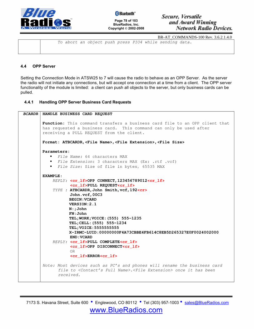
Page 78 of 103
BlueRadios, Inc. Copyright © 2002-2008
BR-AT_COMMANDS-100 Rev. 3.6.2.1.4.0
7173 S. Havana Street, Suite 600 • Englewood, CO 80112 • Tel (303) 957-1003 • [email protected]
www.BlueRadios.com
To abort an object push press PIO4 while sending data.
4.4 OPP Server Setting the Connection Mode in ATSW25 to 7 will cause the radio to behave as an OPP Server. As the server the radio will not initiate any connections, but will accept one connection at a time from a client. The OPP server functionality of the module is limited: a client can push all objects to the server, but only business cards can be pulled.
4.4.1 Handling OPP Server Business Card Requests BCARDR HANDLE BUSINESS CARD REQUEST
Function: This command transfers a business card file to an OPP client that has requested a business card. This command can only be used after receiving a PULL REQUEST from the client. Format: ATBCARDR,<File Name>,<File Extension>,<File Size> Parameters:
File Name: 64 characters MAX File Extension: 3 characters MAX (Ex: .rtf .vcf) File Size: Size of file in bytes, 65535 MAX
EXAMPLE: REPLY: <cr_lf>OPP CONNECT,123456789012<cr_lf> <cr_lf>PULL REQUEST<cr_lf> TYPE : ATBCARDR,John Smith,vcf,192<cr> John.vcf,00C3
BEGIN:VCARD VERSION:2.1 N:;John FN:John TEL;WORK;VOICE:(555) 555-1235 TEL;CELL:(555) 555-1234 TEL;VOICE:5555555555 X-IRMC-LUID:00000000F4A73CBBE4FB614C8EB5D265327E0F0024002000
END:VCARD REPLY: <cr_lf>PULL COMPLETE<cr_lf> <cr_lf>OPP DISCONNECT<cr_lf> OR <cr_lf>ERROR<cr_lf> Note: Most devices such as PC’s and phones will rename the business card
file to <Contact’s Full Name>.<File Extension> once it has been received.
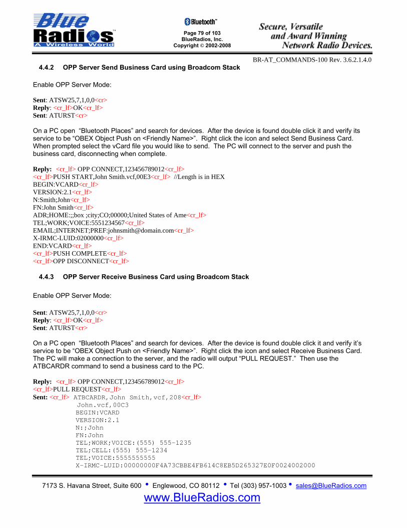
Page 79 of 103
BlueRadios, Inc. Copyright © 2002-2008
BR-AT_COMMANDS-100 Rev. 3.6.2.1.4.0
7173 S. Havana Street, Suite 600 • Englewood, CO 80112 • Tel (303) 957-1003 • [email protected]
www.BlueRadios.com
4.4.2 OPP Server Send Business Card using Broadcom Stack Enable OPP Server Mode: Sent: ATSW25,7,1,0,0<cr> Reply: <cr_lf>OK<cr_lf> Sent: ATURST<cr> On a PC open “Bluetooth Places” and search for devices. After the device is found double click it and verify its service to be “OBEX Object Push on <Friendly Name>”. Right click the icon and select Send Business Card. When prompted select the vCard file you would like to send. The PC will connect to the server and push the business card, disconnecting when complete. Reply: <cr_lf> OPP CONNECT,123456789012<cr_lf> <cr_lf>PUSH START,John Smith.vcf,00E3<cr_lf> //Length is in HEX BEGIN:VCARD<cr_lf> VERSION:2.1<cr_lf> N:Smith;John<cr_lf> FN:John Smith<cr_lf> ADR;HOME:;;box ;city;CO;00000;United States of Ame<cr_lf> TEL;WORK;VOICE:5551234567<cr_lf> EMAIL;INTERNET;PREF:[email protected]<cr_lf> X-IRMC-LUID:02000000<cr_lf> END:VCARD<cr_lf> <cr_lf>PUSH COMPLETE<cr_lf> <cr_lf>OPP DISCONNECT<cr_lf>
4.4.3 OPP Server Receive Business Card using Broadcom Stack Enable OPP Server Mode: Sent: ATSW25,7,1,0,0<cr> Reply: <cr_lf>OK<cr_lf> Sent: ATURST<cr> On a PC open “Bluetooth Places” and search for devices. After the device is found double click it and verify it’s service to be “OBEX Object Push on <Friendly Name>”. Right click the icon and select Receive Business Card. The PC will make a connection to the server, and the radio will output “PULL REQUEST.” Then use the ATBCARDR command to send a business card to the PC. Reply: <cr_lf> OPP CONNECT,123456789012<cr_lf> <cr_lf>PULL REQUEST<cr_lf> Sent: <cr_lf> ATBCARDR,John Smith,vcf,208<cr_lf> John.vcf,00C3
BEGIN:VCARD VERSION:2.1 N:;John FN:John TEL;WORK;VOICE:(555) 555-1235 TEL;CELL:(555) 555-1234 TEL;VOICE:5555555555 X-IRMC-LUID:00000000F4A73CBBE4FB614C8EB5D265327E0F0024002000

Page 80 of 103
BlueRadios, Inc. Copyright © 2002-2008
BR-AT_COMMANDS-100 Rev. 3.6.2.1.4.0
7173 S. Havana Street, Suite 600 • Englewood, CO 80112 • Tel (303) 957-1003 • [email protected]
www.BlueRadios.com
END:VCARD Reply:<cr_lf>PULL COMPLETE<cr_lf> <cr_lf>OPP DISCONNECT<cr_lf>
4.4.4 OPP Server Send Data using TransSend Enable OPP Server mode and set the COD of the device to a known COD, such as that of a laptop so that TransSend will discover the radio. Sent: ATSW25,7,1,0,0<cr> Reply: <cr_lf>OK<cr_lf> Sent: ATSC,0072010c<cr> // TransSend uses COD filtering, so use a known COD. Reply: <cr_lf>OK<cr_lf> Sent: ATURST<cr> Open your browser and find the picture or block of text you would like to send. After you have done this highlight all you wish to send then right click it and go to “TransSend to device with Bluetooth” and click note or picture. Wait for TransSend to search for devices and select the desired device. If sending text select “Plain Text,” to send the data click OK. Reply: <cr_lf> OPP CONNECT,123456789012<cr_lf> <cr_lf>PUSH START,John Smith.vcf,0015<cr_lf> //Length is in HEX This is a test note.<cr_lf> <cr_lf>PUSH COMPLETE<cr_lf> <cr_lf>OPP DISCONNECT<cr_lf>
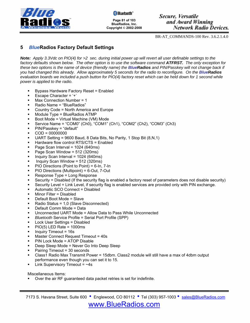
Page 81 of 103
BlueRadios, Inc. Copyright © 2002-2008
BR-AT_COMMANDS-100 Rev. 3.6.2.1.4.0
7173 S. Havana Street, Suite 600 • Englewood, CO 80112 • Tel (303) 957-1003 • [email protected]
www.BlueRadios.com
5 BlueRadios Factory Default Settings Note: Apply 3.3Vdc on PIO(4) for >2 sec. during initial power up will revert all user definable settings to the factory defaults shown below. The other option is to use the software command ATFRST. The only exception for these two options is the name of device (friendly name) the BlueRadios and PIN/Passkey will not change back if you had changed this already. Allow approximately 5 seconds for the radio to reconfigure. On the BlueRadios evaluation boards we included a push button for PIO(4) factory reset which can be held down for 1 second while power is applied to the radio.
Bypass Hardware Factory Reset = Enabled Escape Character = ‘+’ Max Connection Number = 1 Radio Name = “BlueRadios” Country Code = North America and Europe Module Type = BlueRadios ATMP Boot Mode = Virtual Machine (VM) Mode Service Name = “COM0” (Ch0), “COM1” (Ch1), “COM2” (Ch2), “COM3” (Ch3) PIN/Passkey = “default” COD = 00000000 UART Setting = 9600 Baud, 8 Data Bits, No Parity, 1 Stop Bit (8,N,1) Hardware flow control RTS/CTS = Enabled Page Scan Interval = 1024 (640ms) Page Scan Window = 512 (320ms) Inquiry Scan Interval = 1024 (640ms) Inquiry Scan Window = 512 (320ms) PIO Directions (Point to Point) = 6-In, 7-In PIO Directions (Multipoint) = 6-Out, 7-Out Response Type = Long Response Security = Disabled (If the security flag is enabled a factory reset of parameters does not disable security) Security Level = Link Level, if security flag is enabled services are provided only with PIN exchange. Automatic SCO Connect = Disabled Minor Filter = Disabled Default Boot Mode = Slave Radio Status = 1,0 (Slave Disconnected) Default Comm Mode = Data Unconnected UART Mode = Allow Data to Pass While Unconnected Bluetooth Service Profile = Serial Port Profile (SPP) Lock User Settings = Disabled PIO(5) LED Rate = 1000ms Inquiry Timeout = 16s Master Connect Request Timeout = 40s PIN Lock Mode = ATOP Disable Deep Sleep Mode = Never Go Into Deep Sleep Pairing Timeout = 30 seconds Class1 Radio Max Transmit Power = 15dbm. Class2 module will still have a max of 4dbm output
performance even though you can set it to 15. Link Supervisory Timeout = ~4s
Miscellaneous Items: Over the air RF guaranteed data packet retries is set for indefinite.

Page 82 of 103
BlueRadios, Inc. Copyright © 2002-2008
BR-AT_COMMANDS-100 Rev. 3.6.2.1.4.0
7173 S. Havana Street, Suite 600 • Englewood, CO 80112 • Tel (303) 957-1003 • [email protected]
www.BlueRadios.com
6 BlueRadios Class1 Module Power Consumptions Idle Mode ≈ 1.4mA average Deep Sleep Mode ≈ 25-50uA (Idle Mode)
If in Sniff Mode, will go momentarily as low as 50uA in between processes. Slave Unconnected ≈ 39mA average
ATSW21,4096,18,4096,18 settings will result in the Slave not connected ≈ 1mA average. ATSW21,4096,18,4096,18 settings along with enabling Deep Sleep Mode will result in an unconnected
slave current draw of ≈ 350uA average. Master Unconnected ≈ 1.4mA average
A Master radio not in use it is better to just turn off the power completely to the radio and draw zero current.
Master Inquiry ≈ 60mA average
For the first couple of seconds before it connects to the Slave Connected ≈ 5mA average
ATSNIFF,1600,160,10,160 will result in the Slave connected ≈ 1.4mA average, with no data being sent. This can even go as low as 0.6mA if you make the Slave not discoverable but connectable.
If you perform a remote Bluetooth RF “ATDH” disconnect command from any Master to the BlueRadios Slave radio, the Slave radio will go into idle mode. You will have to either send a command to the Slave radio through its local UART or cycle power on the radios to have it come back up in Slave mode. This was designed as if you were communicating to the local UART on the Slave radio. Typically a Slave never sends a commanded disconnect only the Master does. In this mode you can devise some clever power saving features like leaving the Slave in idle mode until another event triggers the radio to go back into Slave discoverable mode. It is important to remember a device in Idle Mode is not discoverable which has some security advantages. The same sort of benefits can be achieved by just controlling when the radio is turned off/on again.

Page 83 of 103
BlueRadios, Inc. Copyright © 2002-2008
BR-AT_COMMANDS-100 Rev. 3.6.2.1.4.0
7173 S. Havana Street, Suite 600 • Englewood, CO 80112 • Tel (303) 957-1003 • [email protected]
www.BlueRadios.com
7 Example Connection Sequences
7.1 Master Discovery/Connection Sequence From power up and no connection:
1) Perform an Inquiry to obtain BT Address’s (unless it is already known).
Sent : ATUCL<cr> // Clears radio state and places in Idle Mode Reply:<cr_lf>OK<cr_lf> Sent : ATDI,1,00000000 Class of Device<cr> // Looks for only one Bluetooth device Reply:<cr_lf>00A0961F2023,00000104,BLUERADIOS<cr_lf>
<cr_lf>DONE<cr_lf>
2) Perform a Master Connect over SPP using the BT Address.
Sent : ATDM, 00A0961F2023,1101<cr> // SPP connection Reply:<cr_lf>CONNECT,00A0961F008F <cr_lf> // Returns Slave BT address radios is in Data Mode
3) Place radio into Fast Data Mode
Sent : +++<cr> // Places radio Command Mode Reply:<cr_lf>OK<cr_lf> Sent : ATMF<cr> // Places radio in Fast Data Mode Reply:<cr_lf>OK<cr_lf>
4) Send Data.
Note: When sending commands from the Slave when the Slave connects in Fast Data Mode (ATSW25/or issuing ATMF). All valid AT commands are sent through the Slaves UART will be interpreted and responded by the Master radio as if it was the local Slave radio. Basically in this configuration from the Slave end you can obtain status and configure from the remote Master radio. This is a unique feature that may be useful in some applications but can confuse the user if you think you are talking to the local Slave UART. To get out of Data Mode and check status:
1) Delay at least 50 milliseconds; this could be less or more. 2) Get into Command Mode.
Sent : +++<cr> // Default escape sequence of characters Reply:<cr_lf>OK<cr_lf>
3) Check Status
Sent : AT<cr> Reply:<cr_lf>OK<cr_lf>
4) Or send any AT Command example:
Sent : ATSI,0<cr>
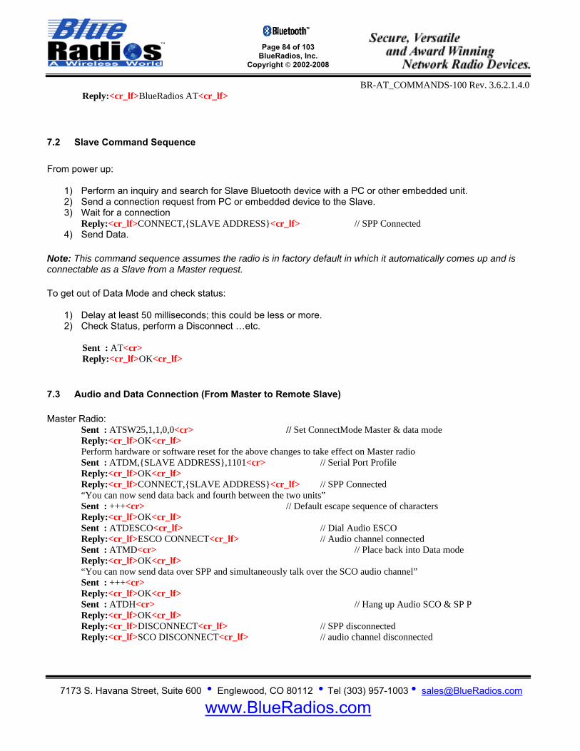
Page 84 of 103
BlueRadios, Inc. Copyright © 2002-2008
BR-AT_COMMANDS-100 Rev. 3.6.2.1.4.0
7173 S. Havana Street, Suite 600 • Englewood, CO 80112 • Tel (303) 957-1003 • [email protected]
www.BlueRadios.com
Reply:<cr_lf>BlueRadios AT<cr_lf>
7.2 Slave Command Sequence From power up:
1) Perform an inquiry and search for Slave Bluetooth device with a PC or other embedded unit. 2) Send a connection request from PC or embedded device to the Slave. 3) Wait for a connection
Reply:<cr_lf>CONNECT,SLAVE ADDRESS<cr_lf> // SPP Connected 4) Send Data.
Note: This command sequence assumes the radio is in factory default in which it automatically comes up and is connectable as a Slave from a Master request. To get out of Data Mode and check status:
1) Delay at least 50 milliseconds; this could be less or more. 2) Check Status, perform a Disconnect …etc.
Sent : AT<cr> Reply:<cr_lf>OK<cr_lf>
7.3 Audio and Data Connection (From Master to Remote Slave) Master Radio:
Sent : ATSW25,1,1,0,0<cr> // Set ConnectMode Master & data mode Reply:<cr_lf>OK<cr_lf> Perform hardware or software reset for the above changes to take effect on Master radio Sent : ATDM,SLAVE ADDRESS,1101<cr> // Serial Port Profile Reply:<cr_lf>OK<cr_lf> Reply:<cr_lf>CONNECT,SLAVE ADDRESS<cr_lf> // SPP Connected “You can now send data back and fourth between the two units” Sent : +++<cr> // Default escape sequence of characters Reply:<cr_lf>OK<cr_lf> Sent : ATDESCO<cr_lf> // Dial Audio ESCO Reply:<cr_lf>ESCO CONNECT<cr_lf> // Audio channel connected Sent : ATMD<cr> // Place back into Data mode Reply:<cr_lf>OK<cr_lf> “You can now send data over SPP and simultaneously talk over the SCO audio channel” Sent : +++<cr> Reply:<cr_lf>OK<cr_lf> Sent : ATDH<cr> // Hang up Audio SCO & SP P Reply:<cr_lf>OK<cr_lf> Reply:<cr_lf>DISCONNECT<cr_lf> // SPP disconnected Reply:<cr_lf>SCO DISCONNECT<cr_lf> // audio channel disconnected

Page 85 of 103
BlueRadios, Inc. Copyright © 2002-2008
BR-AT_COMMANDS-100 Rev. 3.6.2.1.4.0
7173 S. Havana Street, Suite 600 • Englewood, CO 80112 • Tel (303) 957-1003 • [email protected]
www.BlueRadios.com
Note: Using ATDHSCO will disconnect audio channel but you will need to type ATMD to go back into data mode to send characters.
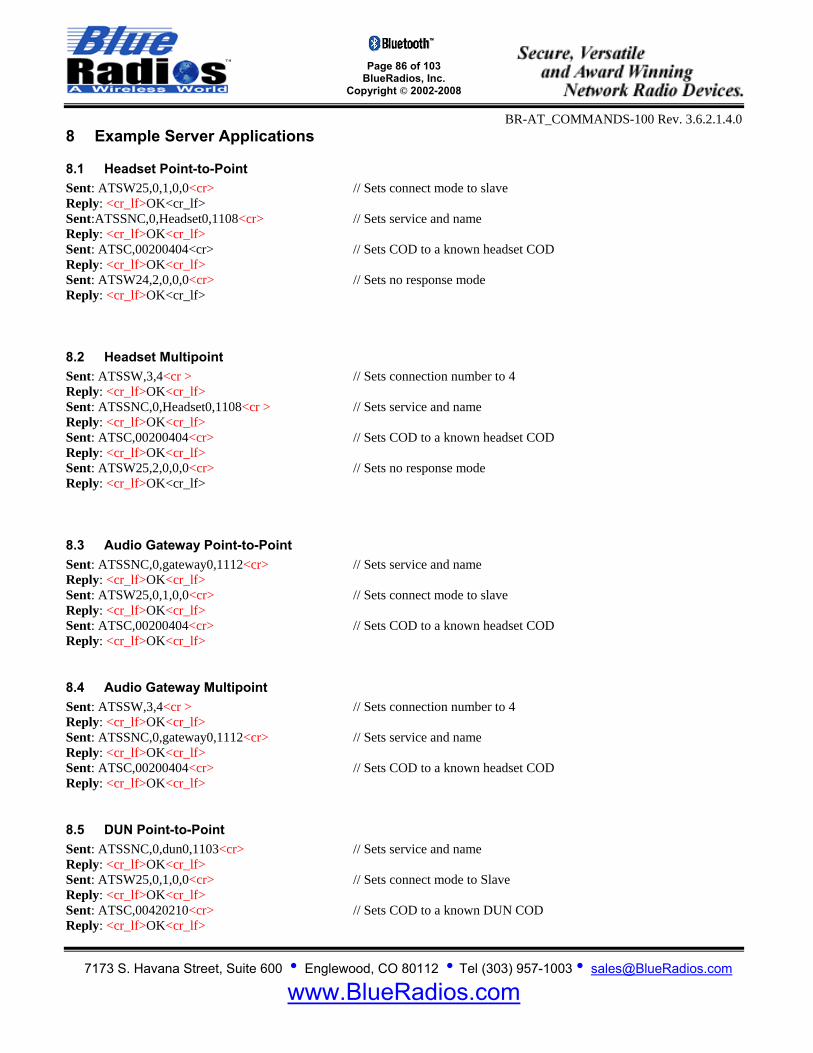
Page 86 of 103
BlueRadios, Inc. Copyright © 2002-2008
BR-AT_COMMANDS-100 Rev. 3.6.2.1.4.0
7173 S. Havana Street, Suite 600 • Englewood, CO 80112 • Tel (303) 957-1003 • [email protected]
www.BlueRadios.com
8 Example Server Applications
8.1 Headset Point-to-Point Sent: ATSW25,0,1,0,0<cr> // Sets connect mode to slave Reply: <cr_lf>OK<cr_lf> Sent:ATSSNC,0,Headset0,1108<cr> // Sets service and name Reply: <cr_lf>OK<cr_lf> Sent: ATSC,00200404<cr> // Sets COD to a known headset COD Reply: <cr_lf>OK<cr_lf> Sent: ATSW24,2,0,0,0<cr> // Sets no response mode Reply: <cr_lf>OK<cr_lf>
8.2 Headset Multipoint Sent: ATSSW,3,4<cr > // Sets connection number to 4 Reply: <cr_lf>OK<cr_lf> Sent: ATSSNC,0,Headset0,1108<cr > // Sets service and name Reply: <cr_lf>OK<cr_lf> Sent: ATSC,00200404<cr> // Sets COD to a known headset COD Reply: <cr_lf>OK<cr_lf> Sent: ATSW25,2,0,0,0<cr> // Sets no response mode Reply: <cr_lf>OK<cr_lf>
8.3 Audio Gateway Point-to-Point Sent: ATSSNC,0,gateway0,1112<cr> // Sets service and name Reply: <cr_lf>OK<cr_lf> Sent: ATSW25,0,1,0,0<cr> // Sets connect mode to slave Reply: <cr_lf>OK<cr_lf> Sent: ATSC,00200404<cr> // Sets COD to a known headset COD Reply: <cr_lf>OK<cr_lf>
8.4 Audio Gateway Multipoint Sent: ATSSW,3,4<cr > // Sets connection number to 4 Reply: <cr_lf>OK<cr_lf> Sent: ATSSNC,0,gateway0,1112<cr> // Sets service and name Reply: <cr_lf>OK<cr_lf> Sent: ATSC,00200404<cr> // Sets COD to a known headset COD Reply: <cr_lf>OK<cr_lf>
8.5 DUN Point-to-Point Sent: ATSSNC,0,dun0,1103<cr> // Sets service and name Reply: <cr_lf>OK<cr_lf> Sent: ATSW25,0,1,0,0<cr> // Sets connect mode to Slave Reply: <cr_lf>OK<cr_lf> Sent: ATSC,00420210<cr> // Sets COD to a known DUN COD Reply: <cr_lf>OK<cr_lf>

Page 87 of 103
BlueRadios, Inc. Copyright © 2002-2008
BR-AT_COMMANDS-100 Rev. 3.6.2.1.4.0
7173 S. Havana Street, Suite 600 • Englewood, CO 80112 • Tel (303) 957-1003 • [email protected]
www.BlueRadios.com
8.6 DUN Multipoint Sent: ATSSW,3,4<cr> // Sets connection number to 4 Reply: <cr_lf>OK<cr_lf> Sent: ATSSNC,0,dun0,1103<cr> // Sets service and name Reply: <cr_lf>OK<cr_lf> Sent: ATSC,00420210<cr> // Sets COD to a known DUN COD Reply: <cr_lf>OK<cr_lf>
8.7 LAN Point-to-Point Sent: ATSSNC,0,lan0,1102<cr> // Sets service and name Reply: <cr_lf>OK<cr_lf> Sent: ATSW25,0,1,0,0<cr> // Sets connect mode to slave Reply: <cr_lf>OK<cr_lf> Sent: ATSC,00020300<cr> // Sets COD to a known LAN COD Reply: <cr_lf>OK<cr_lf>
8.8 LAN Multipoint Sent: ATSSW,3,4<cr > // Sets connection number to 4 Reply: <cr_lf>OK<cr_lf> Sent: ATSSNC,0,lan0,1102<cr> // Sets service and name Reply: <cr_lf>OK<cr_lf> Sent: ATSC,00020300<cr> // Sets COD to a known LAN COD Reply: <cr_lf>OK<cr_lf> 9 Example Client Applications
9.1 Audio Gateway Only supports the connection. Sent: ATSW24,0,0,1,0<cr> // Sets Auto SCO Reply: <cr_lf>OK<cr_lf> Sent: ATSC,00200404<cr> // Sets COD to a known headset COD Reply: <cr_lf>OK<cr_lf> Sent: ATDM,<Headset Address>,1112<cr> Reply: <cr_lf>OK<cr_lf>
9.2 DUN Only supports the connection. Sent: ATSC,00420210<cr> // Sets COD to a known DUN COD Reply: <cr_lf>OK<cr_lf> Sent: ATDM, <DUN Address>,1103<cr> // Sets auto connect address Reply: <cr_lf>OK<cr_lf>

Page 88 of 103
BlueRadios, Inc. Copyright © 2002-2008
BR-AT_COMMANDS-100 Rev. 3.6.2.1.4.0
7173 S. Havana Street, Suite 600 • Englewood, CO 80112 • Tel (303) 957-1003 • [email protected]
www.BlueRadios.com
10 Acronyms/Abbreviations API - Application Protocol Interface AT – Attention ATMP – Attention Multi Point ASCII - American Standard Code for Information Interchange BCSP - Blue Core Serial Port BNEP - Bluetooth Networking Encapsulation Protocol BR - BlueRadios BT - Bluetooth BTW - Bluetooth Windows Stack COD - Class Of Device COM - Communications CR - Carriage Return CTS - Clear To Send DSR - Data Sent Receive eSCO – Enhanced Synchronous Connection-Oriented: the links used by BT to send exceptional audio clarity. GND - Ground HCI - Host Controller Interface IP – Internet Protocol LF - Line Feed MCU - Microcontroller Unit MISO - Master In Slave Out MOSI – Master Out Slave In NC - Not Connected PC - Personal Computer PCB - Printed Circuit Board PCM - Pulse Code Modulation PAN - Personnel Area Networking PIN/Passkey - Personal Identification Number RF - Radio Frequency PIO - Pin Input/Output RST - Reset RTS - Ready To Send RX - Receive SCO - Synchronous Connection-Oriented: the links used by BT to send audio. SMT - Surface Mount Technology SPI - Serial Protocol Interface SPICK - SPI Clock SPICS - SPI Chip Select TTL - Transistor Transistor Logic TX - Transmit UART - Universal Asynchronous Receiver/Transmitter USB - Universal Serial Bus UUID - Universal Unique Identifier – maintain by Bluetooth SIG. VCC - DC Power VDD - DC Power VM – Virtual Machine Go to www.blueradios.com and look on the left hand column to download Bluetooth Glossary of Terms PDF and other materials.

Page 89 of 103
BlueRadios, Inc. Copyright © 2002-2008
BR-AT_COMMANDS-100 Rev. 3.6.2.1.4.0
7173 S. Havana Street, Suite 600 • Englewood, CO 80112 • Tel (303) 957-1003 • [email protected]
www.BlueRadios.com
APPENDIX A: AT Command Summary Table
AT Command Description Requires Reset
Stores Permanently
Attention Prefix AT Attention Prefix N/A N/A Firmware Version ATVER,ver1 Module Firmware Version N/A Yes Resetting ATURST Unit Reset N/A N/A ATFRST Factory Reset N/A N/A ATSSW,0 Set Bypass PIO(4) Factory Reconfiguration Yes Yes ATRSW,0 Read Bypass PIO(4) Factory Reconfiguration N/A Yes Boot Mode ATSSW,1 Set Boot Mode Yes Yes ATRSW,1 Get Boot Mode N/A N/A Security Level ATSSW,2 Set Security Level Yes Yes ATRSW,2 Get Security Level N/A N/A Get Status ATSI,0 Get Module Type N/A Yes ATSI,1 Get Bluetooth Address N/A Yes ATSI,2 Get Friendly Name N/A YesATSI,3 Get Current Status of Connections N/A YesATSI,4 Get Service Name N/A YesATSI,5 Get Class of Device (COD) N/A YesATSI,6 Get Response, Security, Auto SCO, Filter Settings N/A YesATSI,7 Get Connection, Comm, UART, Service Modes N/A YesATSI,8 Get UART Settings N/A YesATSI,9 Get Master Auto-Connect Address N/A YesATSI,10 Get Slave Scan Intervals and Windows N/A YesATSI,11 Get PIO(5) Pulse Rate N/A YesATSI,12 Get Escape Character N/A YesATSI,13 Get Timeout Settings N/A YesATSI,14 Get Maximum TX Power Level N/A YesATSI,15 Get PIN Lock Mode N/A YesATSI,16 Get Deep Sleep Mode N/A YesATSI,17 Get Sniff Settings N/A YesATSI,18 Get Link Supervisory Timeout N/A YesATSI,19 Get List of Paired or Secured Addresses N/A YesATSI,20 Get Channel UUIDs N/A Yes ATSI,21 Get Specific Transmission Channel N/A Yes ATSI,22 Get FTP/OPP Connection Status N/A Yes ATSI,23 Get test data settings N/A Yes
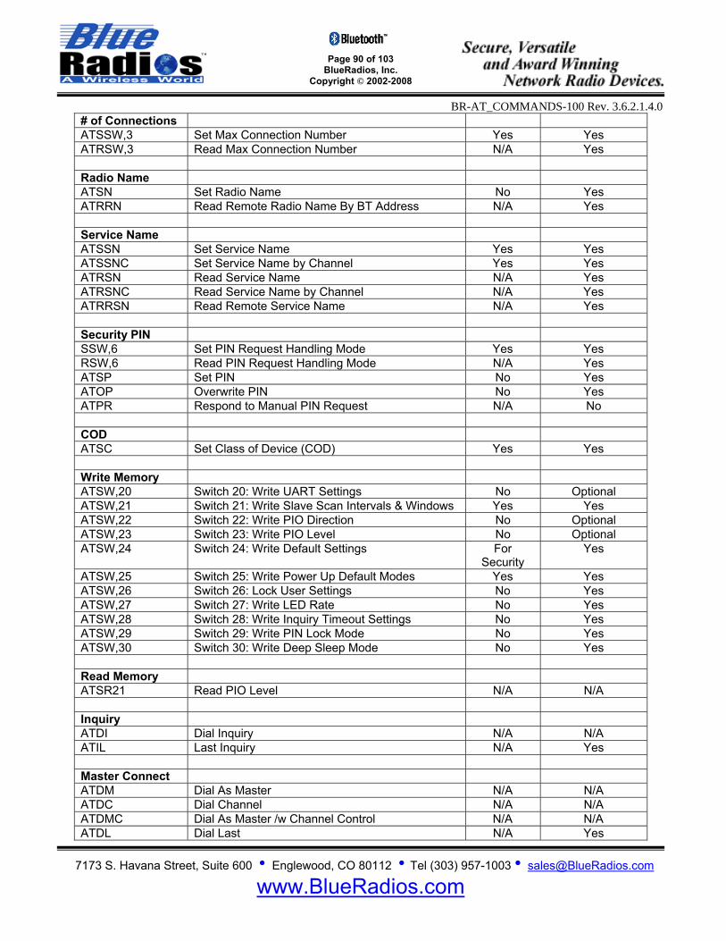
Page 90 of 103
BlueRadios, Inc. Copyright © 2002-2008
BR-AT_COMMANDS-100 Rev. 3.6.2.1.4.0
7173 S. Havana Street, Suite 600 • Englewood, CO 80112 • Tel (303) 957-1003 • [email protected]
www.BlueRadios.com
# of Connections ATSSW,3 Set Max Connection Number Yes Yes ATRSW,3 Read Max Connection Number N/A Yes Radio Name ATSN Set Radio Name No Yes ATRRN Read Remote Radio Name By BT Address N/A Yes Service Name ATSSN Set Service Name Yes Yes ATSSNC Set Service Name by Channel Yes Yes ATRSN Read Service Name N/A Yes ATRSNC Read Service Name by Channel N/A Yes ATRRSN Read Remote Service Name N/A Yes Security PIN SSW,6 Set PIN Request Handling Mode Yes Yes RSW,6 Read PIN Request Handling Mode N/A Yes ATSP Set PIN No Yes ATOP Overwrite PIN No Yes ATPR Respond to Manual PIN Request N/A No COD ATSC Set Class of Device (COD) Yes Yes Write Memory ATSW,20 Switch 20: Write UART Settings No Optional ATSW,21 Switch 21: Write Slave Scan Intervals & Windows Yes Yes ATSW,22 Switch 22: Write PIO Direction No Optional ATSW,23 Switch 23: Write PIO Level No Optional ATSW,24 Switch 24: Write Default Settings For
Security Yes
ATSW,25 Switch 25: Write Power Up Default Modes Yes Yes ATSW,26 Switch 26: Lock User Settings No Yes ATSW,27 Switch 27: Write LED Rate No Yes ATSW,28 Switch 28: Write Inquiry Timeout Settings No Yes ATSW,29 Switch 29: Write PIN Lock Mode No Yes ATSW,30 Switch 30: Write Deep Sleep Mode No Yes Read Memory ATSR21 Read PIO Level N/A N/A Inquiry ATDI Dial Inquiry N/A N/A ATIL Last Inquiry N/A Yes Master Connect ATDM Dial As Master N/A N/A ATDC Dial Channel N/A N/A ATDMC Dial As Master /w Channel Control N/A N/A ATDL Dial Last N/A Yes
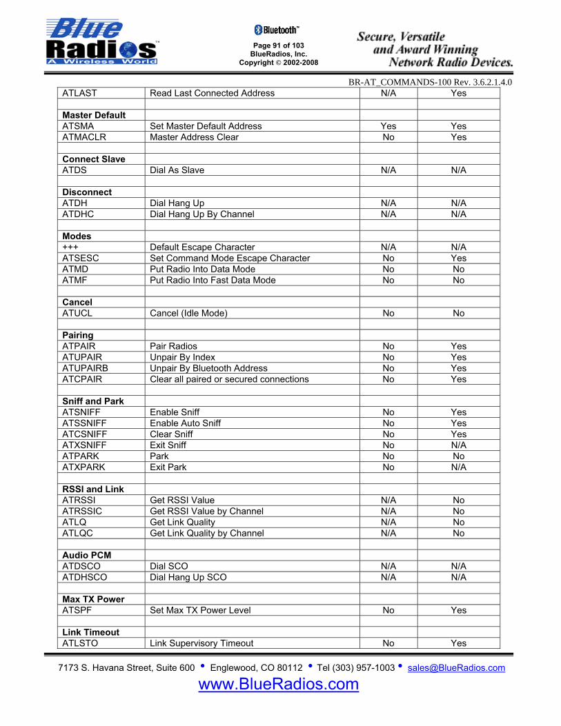
Page 91 of 103
BlueRadios, Inc. Copyright © 2002-2008
BR-AT_COMMANDS-100 Rev. 3.6.2.1.4.0
7173 S. Havana Street, Suite 600 • Englewood, CO 80112 • Tel (303) 957-1003 • [email protected]
www.BlueRadios.com
ATLAST Read Last Connected Address N/A Yes Master Default ATSMA Set Master Default Address Yes Yes ATMACLR Master Address Clear No Yes Connect Slave ATDS Dial As Slave N/A N/A Disconnect ATDH Dial Hang Up N/A N/A ATDHC Dial Hang Up By Channel N/A N/A Modes +++ Default Escape Character N/A N/A ATSESC Set Command Mode Escape Character No Yes ATMD Put Radio Into Data Mode No No ATMF Put Radio Into Fast Data Mode No No Cancel ATUCL Cancel (Idle Mode) No No Pairing ATPAIR Pair Radios No Yes ATUPAIR Unpair By Index No Yes ATUPAIRB Unpair By Bluetooth Address No Yes ATCPAIR Clear all paired or secured connections No Yes Sniff and Park ATSNIFF Enable Sniff No Yes ATSSNIFF Enable Auto Sniff No Yes ATCSNIFF Clear Sniff No Yes ATXSNIFF Exit Sniff No N/A ATPARK Park No No ATXPARK Exit Park No N/A RSSI and Link ATRSSI Get RSSI Value N/A No ATRSSIC Get RSSI Value by Channel N/A No ATLQ Get Link Quality N/A No ATLQC Get Link Quality by Channel N/A No Audio PCM ATDSCO Dial SCO N/A N/A ATDHSCO Dial Hang Up SCO N/A N/A Max TX Power ATSPF Set Max TX Power Level No Yes Link Timeout ATLSTO Link Supervisory Timeout No Yes
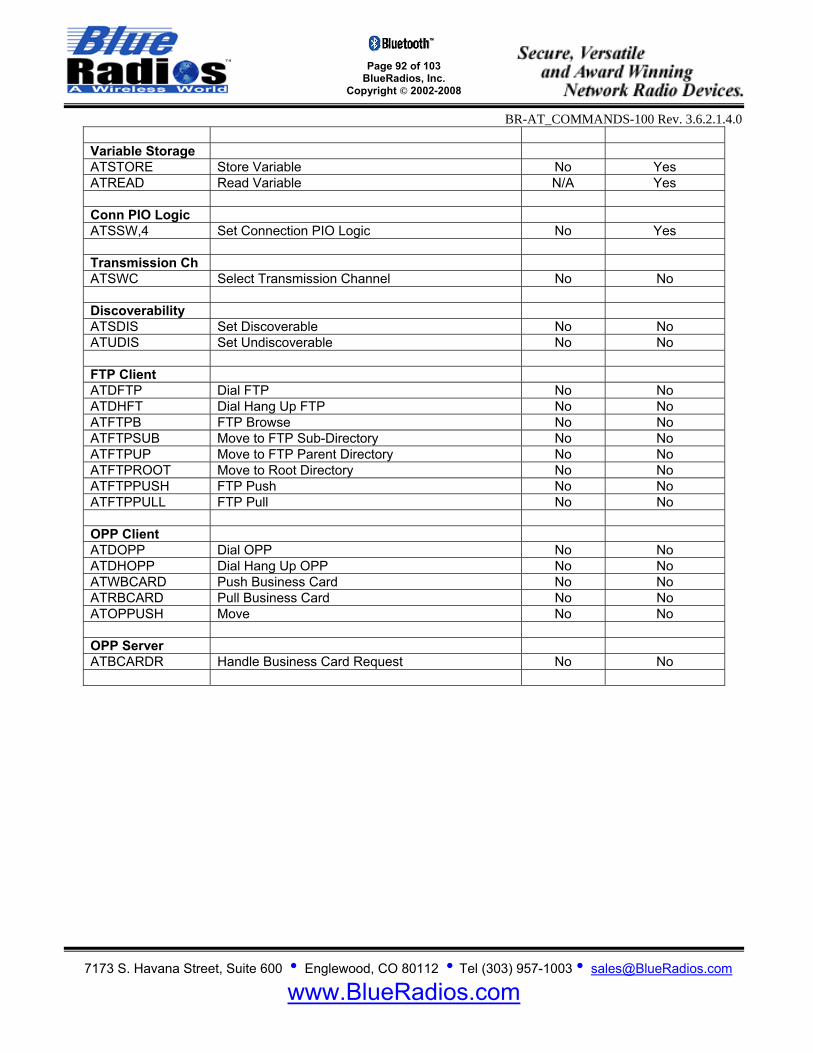
Page 92 of 103
BlueRadios, Inc. Copyright © 2002-2008
BR-AT_COMMANDS-100 Rev. 3.6.2.1.4.0
7173 S. Havana Street, Suite 600 • Englewood, CO 80112 • Tel (303) 957-1003 • [email protected]
www.BlueRadios.com
Variable Storage ATSTORE Store Variable No Yes ATREAD Read Variable N/A Yes Conn PIO Logic ATSSW,4 Set Connection PIO Logic No Yes Transmission Ch ATSWC Select Transmission Channel No No Discoverability ATSDIS Set Discoverable No No ATUDIS Set Undiscoverable No No FTP Client ATDFTP Dial FTP No No ATDHFT Dial Hang Up FTP No No ATFTPB FTP Browse No No ATFTPSUB Move to FTP Sub-Directory No No ATFTPUP Move to FTP Parent Directory No No ATFTPROOT Move to Root Directory No No ATFTPPUSH FTP Push No No ATFTPPULL FTP Pull No No OPP Client ATDOPP Dial OPP No No ATDHOPP Dial Hang Up OPP No No ATWBCARD Push Business Card No No ATRBCARD Pull Business Card No No ATOPPUSH Move No No OPP Server ATBCARDR Handle Business Card Request No No
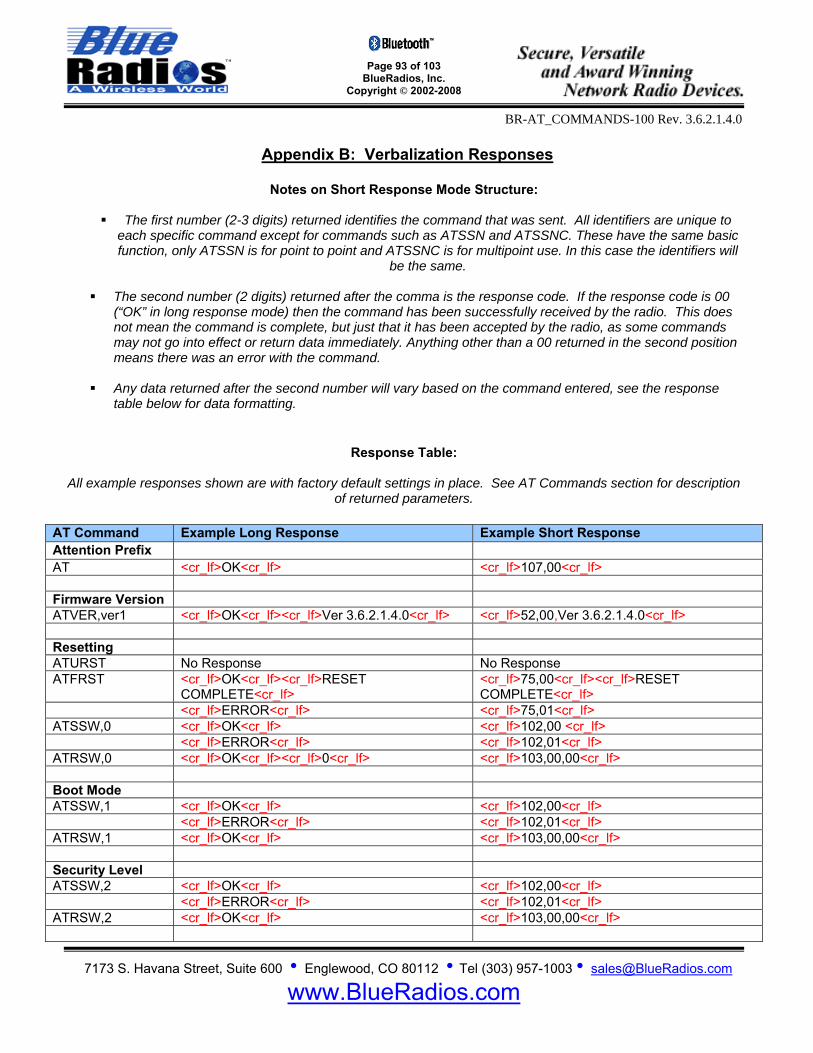
Page 93 of 103
BlueRadios, Inc. Copyright © 2002-2008
BR-AT_COMMANDS-100 Rev. 3.6.2.1.4.0
7173 S. Havana Street, Suite 600 • Englewood, CO 80112 • Tel (303) 957-1003 • [email protected]
www.BlueRadios.com
Appendix B: Verbalization Responses
Notes on Short Response Mode Structure:
The first number (2-3 digits) returned identifies the command that was sent. All identifiers are unique to
each specific command except for commands such as ATSSN and ATSSNC. These have the same basic function, only ATSSN is for point to point and ATSSNC is for multipoint use. In this case the identifiers will
be the same.
The second number (2 digits) returned after the comma is the response code. If the response code is 00 (“OK” in long response mode) then the command has been successfully received by the radio. This does not mean the command is complete, but just that it has been accepted by the radio, as some commands may not go into effect or return data immediately. Anything other than a 00 returned in the second position means there was an error with the command.
Any data returned after the second number will vary based on the command entered, see the response
table below for data formatting.
Response Table:
All example responses shown are with factory default settings in place. See AT Commands section for description
of returned parameters.
AT Command Example Long Response Example Short Response Attention Prefix AT <cr_lf>OK<cr_lf> <cr_lf>107,00<cr_lf> Firmware Version ATVER,ver1 <cr_lf>OK<cr_lf><cr_lf>Ver 3.6.2.1.4.0<cr_lf> <cr_lf>52,00,Ver 3.6.2.1.4.0<cr_lf> Resetting ATURST No Response No Response ATFRST <cr_lf>OK<cr_lf><cr_lf>RESET
COMPLETE<cr_lf> <cr_lf>75,00<cr_lf><cr_lf>RESET COMPLETE<cr_lf>
<cr_lf>ERROR<cr_lf> <cr_lf>75,01<cr_lf> ATSSW,0 <cr_lf>OK<cr_lf> <cr_lf>102,00 <cr_lf> <cr_lf>ERROR<cr_lf> <cr_lf>102,01<cr_lf> ATRSW,0 <cr_lf>OK<cr_lf><cr_lf>0<cr_lf> <cr_lf>103,00,00<cr_lf> Boot Mode ATSSW,1 <cr_lf>OK<cr_lf> <cr_lf>102,00<cr_lf> <cr_lf>ERROR<cr_lf> <cr_lf>102,01<cr_lf> ATRSW,1 <cr_lf>OK<cr_lf> <cr_lf>103,00,00<cr_lf> Security Level ATSSW,2 <cr_lf>OK<cr_lf> <cr_lf>102,00<cr_lf> <cr_lf>ERROR<cr_lf> <cr_lf>102,01<cr_lf> ATRSW,2 <cr_lf>OK<cr_lf> <cr_lf>103,00,00<cr_lf>

Page 94 of 103
BlueRadios, Inc. Copyright © 2002-2008
BR-AT_COMMANDS-100 Rev. 3.6.2.1.4.0
7173 S. Havana Street, Suite 600 • Englewood, CO 80112 • Tel (303) 957-1003 • [email protected]
www.BlueRadios.com
Get Status ATSI,0 <cr_lf>OK<cr_lf><cr_lf>BlueRadios
ATMP<cr_lf> <cr_lf>16,00,BlueRadios ATMP<cr_lf>
ATSI,1 <cr_lf>OK<cr_lf><cr_lf>00A09608F513<cr_lf> <cr_lf>14,00,123456789012<cr_lf> ATSI,2 <cr_lf>OK<cr_lf><cr_lf>BlueRadios<cr_lf> <cr_lf>53,00,0B,BlueRadios<cr_lf> ATSI,3 <cr_lf>OK<cr_lf><cr_lf>0,0<cr_lf> <cr_lf>17,00,0,0<cr_lf> ATSI,4 <cr_lf>OK<cr_lf><cr_lf>COM0<cr_lf> <cr_lf>18,00,COM0<cr_lf> ATSI,5 <cr_lf>OK<cr_lf><cr_lf>00000000<cr_lf> <cr_lf>19,00,00000000<cr_lf> ATSI,6 <cr_lf>OK<cr_lf><cr_lf>0,0,0,0<cr_lf> <cr_lf>20,00,1,0,0,0<cr_lf> ATSI,7 <cr_lf>OK<cr_lf><cr_lf>0,1,0,0<cr_lf> <cr_lf>21,00,0,1,0,0<cr_lf> ATSI,8 <cr_lf>OK<cr_lf><cr_lf>0027,0000,0000<cr_lf> <cr_lf>22,00,0027,0000,0000<cr_lf> ATSI,9 <cr_lf>OK<cr_lf><cr_lf>Not Set!<cr_lf> <cr_lf>23,00,Not Set!<cr_lf> ATSI,10 <cr_lf>OK<cr_lf><cr_lf>0400,0200,0400,0200<
cr_lf> <cr_lf>24,00,0400,0200,0400,0200<cr_lf>
ATSI,11 <cr_lf>OK<cr_lf><cr_lf>03E8<cr_lf> <cr_lf>25,00,03E8<cr_lf> ATSI,12 <cr_lf>OK<cr_lf><cr_lf>2B<cr_lf> <cr_lf>68,00,2B<cr_lf> ATSI,13 <cr_lf>OK<cr_lf><cr_lf>0010,0028,003C<cr_lf> <cr_lf>69,00,0010,0028,003C<cr_lf> ATSI,14 <cr_lf>OK<cr_lf><cr_lf>default<cr_lf> <cr_lf>71,01<cr_lf> ATSI,15 <cr_lf>OK<cr_lf><cr_lf>00<cr_lf> <cr_lf>73,00,00<cr_lf> ATSI,16 <cr_lf>OK<cr_lf><cr_lf>00<cr_lf> <cr_lf>76,00,00<cr_lf> ATSI,17 <cr_lf>OK<cr_lf><cr_lf>Not Set!<cr_lf> <cr_lf>92,00,Not Set!<cr_lf> ATSI,18 <cr_lf>OK<cr_lf><cr_lf>04<cr_lf> <cr_lf>93,00,04<cr_lf> ATSI,19 <cr_lf>OK<cr_lf><cr_lf>00,<cr_lf>01,<cr_lf>02,
<cr_lf>03,<cr_lf> <cr_lf>94,00<cr_lf>00,<cr_lf>01,<cr_lf>02,<cr_lf>03,<cr_lf>
ATSI,20 <cr_lf>OK<cr_lf><cr_lf>1101<cr_lf> <cr_lf>110,00,1101lf> ATSI,21 <cr_lf>OK<cr_lf><cr_lf>00,01<cr_lf> <cr_lf>127,00,00,00<cr_lf> ATSI,22 <cr_lf>OK<cr_lf><cr_lf>1<cr_lf> <cr_lf>131,00,1<cr_lf> ATSI,23 <cr_lf>OK<cr_lf<cr_lf>0000,0000,0000,0000<cr
_lf> <cr_lf>0000,0000,0000<cr_lf> <cr_lf>0000,0000,0000<cr_lf>
<cr_lf>139,00,0000,0000,0000,0000<cr_lf> <cr_lf>0000,0000,0000<cr_lf> <cr_lf>0000,0000,0000<cr_lf>
# of Connections ATSSW,3 <cr_lf>OK<cr_lf> <cr_lf>102,00<cr_lf> <cr_lf>ERROR<cr_lf> <cr_lf>102,01<cr_lf> ATRSW,3 <cr_lf>OK<cr_lf><cr_lf>01<cr_lf> <cr_lf>103,00,01<cr_lf> Radio Name ATSN <cr_lf>OK<cr_lf> <cr_lf>15,00<cr_lf> <cr_lf>ERROR<cr_lf> <cr_lf>15,02<cr_lf> ATRRN <cr_lf>OK<cr_lf><cr_lf>BlueRadios<cr_lf> <cr_lf>109,00,0A,BlueRadios<cr_lf> <cr_lf>OK<cr_lf><cr_lf>NO ANSWER<cr_lf> <cr_lf>109,01<cr_lf> Service Name ATSSN <cr_lf>OK<cr_lf> <cr_lf>38,00<cr_lf> <cr_lf>ERROR<cr_lf> <cr_lf>38,03<cr_lf> ATSSNC <cr_lf>OK<cr_lf> <cr_lf>38,00<cr_lf> <cr_lf>ERROR<cr_lf> <cr_lf>38,03<cr_lf> ATRSN <cr_lf>OK<cr_lf><cr_lf>COM0<cr_lf> <cr_lf>18,00,05,COM0<cr_lf> ATRSNC <cr_lf>OK<cr_lf><cr_lf>COM0<cr_lf> <cr_lf>18,00,05,COM0<cr_lf> ATRRSN <cr_lf>OK<cr_lf><cr_lf>01,Bluetooth Serial <cr_lf>108,00,16,Bluetooth Serial Port<cr_lf>
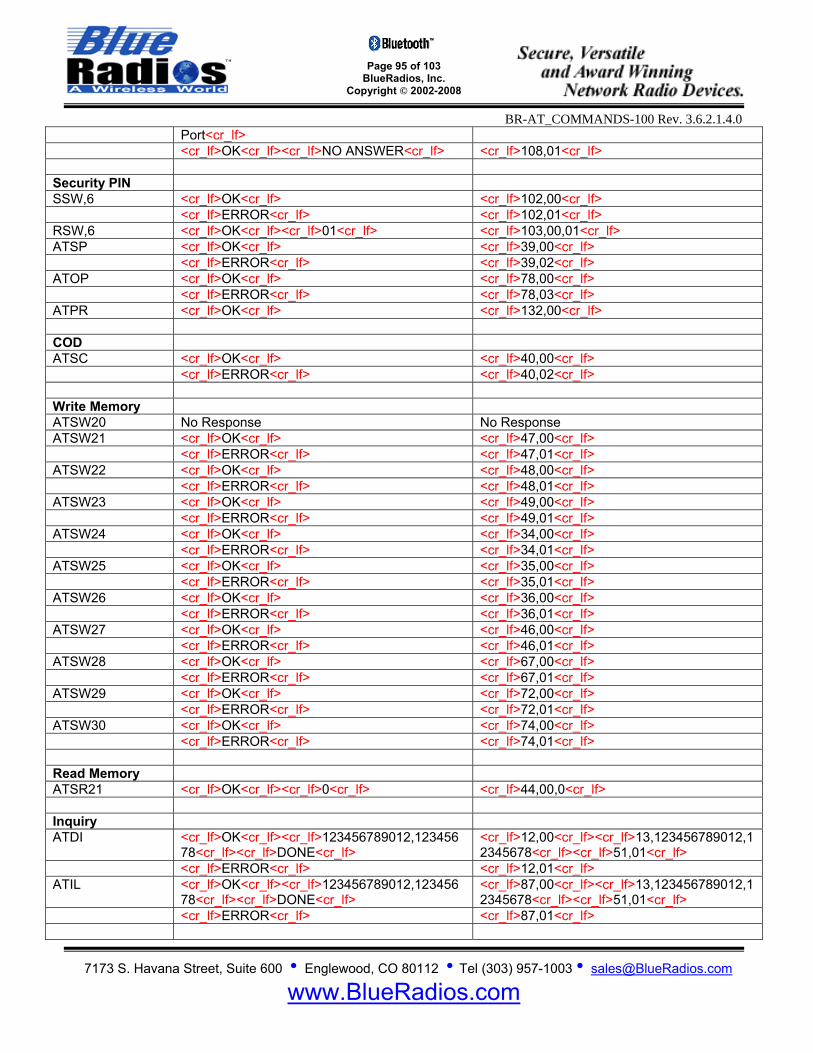
Page 95 of 103
BlueRadios, Inc. Copyright © 2002-2008
BR-AT_COMMANDS-100 Rev. 3.6.2.1.4.0
7173 S. Havana Street, Suite 600 • Englewood, CO 80112 • Tel (303) 957-1003 • [email protected]
www.BlueRadios.com
Port<cr_lf> <cr_lf>OK<cr_lf><cr_lf>NO ANSWER<cr_lf> <cr_lf>108,01<cr_lf> Security PIN SSW,6 <cr_lf>OK<cr_lf> <cr_lf>102,00<cr_lf> <cr_lf>ERROR<cr_lf> <cr_lf>102,01<cr_lf> RSW,6 <cr_lf>OK<cr_lf><cr_lf>01<cr_lf> <cr_lf>103,00,01<cr_lf> ATSP <cr_lf>OK<cr_lf> <cr_lf>39,00<cr_lf> <cr_lf>ERROR<cr_lf> <cr_lf>39,02<cr_lf> ATOP <cr_lf>OK<cr_lf> <cr_lf>78,00<cr_lf> <cr_lf>ERROR<cr_lf> <cr_lf>78,03<cr_lf> ATPR <cr_lf>OK<cr_lf> <cr_lf>132,00<cr_lf> COD ATSC <cr_lf>OK<cr_lf> <cr_lf>40,00<cr_lf> <cr_lf>ERROR<cr_lf> <cr_lf>40,02<cr_lf> Write Memory ATSW20 No Response No Response ATSW21 <cr_lf>OK<cr_lf> <cr_lf>47,00<cr_lf> <cr_lf>ERROR<cr_lf> <cr_lf>47,01<cr_lf> ATSW22 <cr_lf>OK<cr_lf> <cr_lf>48,00<cr_lf> <cr_lf>ERROR<cr_lf> <cr_lf>48,01<cr_lf> ATSW23 <cr_lf>OK<cr_lf> <cr_lf>49,00<cr_lf> <cr_lf>ERROR<cr_lf> <cr_lf>49,01<cr_lf> ATSW24 <cr_lf>OK<cr_lf> <cr_lf>34,00<cr_lf> <cr_lf>ERROR<cr_lf> <cr_lf>34,01<cr_lf> ATSW25 <cr_lf>OK<cr_lf> <cr_lf>35,00<cr_lf> <cr_lf>ERROR<cr_lf> <cr_lf>35,01<cr_lf> ATSW26 <cr_lf>OK<cr_lf> <cr_lf>36,00<cr_lf> <cr_lf>ERROR<cr_lf> <cr_lf>36,01<cr_lf> ATSW27 <cr_lf>OK<cr_lf> <cr_lf>46,00<cr_lf> <cr_lf>ERROR<cr_lf> <cr_lf>46,01<cr_lf> ATSW28 <cr_lf>OK<cr_lf> <cr_lf>67,00<cr_lf> <cr_lf>ERROR<cr_lf> <cr_lf>67,01<cr_lf> ATSW29 <cr_lf>OK<cr_lf> <cr_lf>72,00<cr_lf> <cr_lf>ERROR<cr_lf> <cr_lf>72,01<cr_lf> ATSW30 <cr_lf>OK<cr_lf> <cr_lf>74,00<cr_lf> <cr_lf>ERROR<cr_lf> <cr_lf>74,01<cr_lf> Read Memory ATSR21 <cr_lf>OK<cr_lf><cr_lf>0<cr_lf> <cr_lf>44,00,0<cr_lf> Inquiry ATDI <cr_lf>OK<cr_lf><cr_lf>123456789012,123456
78<cr_lf><cr_lf>DONE<cr_lf> <cr_lf>12,00<cr_lf><cr_lf>13,123456789012,12345678<cr_lf><cr_lf>51,01<cr_lf>
<cr_lf>ERROR<cr_lf> <cr_lf>12,01<cr_lf> ATIL <cr_lf>OK<cr_lf><cr_lf>123456789012,123456
78<cr_lf><cr_lf>DONE<cr_lf> <cr_lf>87,00<cr_lf><cr_lf>13,123456789012,12345678<cr_lf><cr_lf>51,01<cr_lf>
<cr_lf>ERROR<cr_lf> <cr_lf>87,01<cr_lf>

Page 96 of 103
BlueRadios, Inc. Copyright © 2002-2008
BR-AT_COMMANDS-100 Rev. 3.6.2.1.4.0
7173 S. Havana Street, Suite 600 • Englewood, CO 80112 • Tel (303) 957-1003 • [email protected]
www.BlueRadios.com
Master Connect ATDM <cr_lf>OK<cr_lf><cr_lf>CONNECT,1234567890
12<cr_lf> <cr_lf>21,00,123456789012<cr_lf>
(w/Security) <cr_lf>OK<cr_lf><cr_lf>PAIRED,123456789012<cr_lf><cr_lf>CONNECT ,123456789012<cr_lf>
<cr_lf>82,123456789012<cr_lf><cr_lf>21,00,123456789012<cr_lf>
<cr_lf>ERROR<cr_lf> <cr_lf>21,02<cr_lf> <cr_lf>NO ANSWER<cr_lf> <cr_lf>21,04<cr_lf> ATDC <cr_lf>OK<cr_lf><cr_lf>CONNECT
,123456789012<cr_lf> <cr_lf>21,00,123456789012<cr_lf>
(w/Security) <cr_lf>OK<cr_lf><cr_lf>PAIRED,123456789012<cr_lf><cr_lf>CONNECT ,123456789012<cr_lf>
<cr_lf>82,123456789012<cr_lf><cr_lf>21,00,123456789012<cr_lf>
<cr_lf>ERROR<cr_lf> <cr_lf>21,02<cr_lf> <cr_lf>NO ANSWER<cr_lf> <cr_lf>21,04<cr_lf> ATDMC <cr_lf>OK<cr_lf><cr_lf>CONNECT,00,1234567
89012<cr_lf> <cr_lf>21,01,00,123456789012<cr_lf>
<cr_lf>ERROR<cr_lf> <cr_lf>21,02<cr_lf> <cr_lf>NO ANSWER<cr_lf> <cr_lf>21,04<cr_lf> ATDL <cr_lf>OK<cr_lf><cr_lf>CONNECT
,123456789012<cr_lf> <cr_lf>77,00<cr_lf><cr_lf>21,00,123456789012<cr_lf>
(w/Security) <cr_lf>OK<cr_lf><cr_lf>PAIRED,123456789012<cr_lf><cr_lf>CONNECT ,123456789012<cr_lf>
<cr_lf>77,00<cr_lf><cr_lf>82,123456789012<cr_lf><cr_lf>21,00,123456789012<cr_lf>
<cr_lf>ERROR<cr_lf> <cr_lf>77,02<cr_lf> <cr_lf>NO ANSWER<cr_lf> <cr_lf>77,04<cr_lf> ATLAST <cr_lf>OK<cr_lf><cr_lf>123456879012<cr_lf> cr_lf>64,00,123456789012<cr_lf> Master Default ATSMA <cr_lf>OK<cr_lf> <cr_lf>42,00<cr_lf> <cr_lf>ERROR<cr_lf> <cr_lf>42,01<cr_lf> ATMACLR <cr_lf>OK<cr_lf> <cr_lf>43,00<cr_lf> <cr_lf>ERROR<cr_lf> <cr_lf>43,01<cr_lf> ATSSW,7,1 <cr_lf>OK<cr_lf> <cr_lf>102,00<cr_lf> <cr_lf>ERROR<cr_lf> <cr_lf>102,01<cr_lf> RSW,7 <cr_lf>OK<cr_lf><cr_lf>01<cr_lf> <cr_lf>103,00,01<cr_lf> Connect Slave ATDS <cr_lf>OK<cr_lf> <cr_lf>22,00<cr_lf> Disconnect ATDH <cr_lf>OK<cr_lf><cr_lf>DISCONNECT<cr_lf> <cr_lf>23,00<cr_lf> <cr_lf>OK<cr_lf><cr_lf>LINKLOSS<cr_lf> <cr_lf>23,01<cr_lf> <cr_lf>ERROR<cr_lf> <cr_lf>23,02<cr_lf> ATDHC <cr_lf>OK<cr_lf><cr_lf>DISCONNECT,00<cr_lf
> <cr_lf>23,00,00<cr_lf>
<cr_lf>OK<cr_lf><cr_lf>LINKLOSS,00<cr_lf> <cr_lf>23,01,00<cr_lf> <cr_lf>ERROR<cr_lf> <cr_lf>23,03<cr_lf> Modes +++ <cr_lf>OK<cr_lf> <cr_lf>32,00<cr_lf> ATSESC <cr_lf>OK<cr_lf> <cr_lf>65,00<cr_lf> <cr_lf>ERROR<cr_lf> <cr_lf>65,01<cr_lf> ATMD <cr_lf>OK<cr_lf> <cr_lf>31,00<cr_lf>

Page 97 of 103
BlueRadios, Inc. Copyright © 2002-2008
BR-AT_COMMANDS-100 Rev. 3.6.2.1.4.0
7173 S. Havana Street, Suite 600 • Englewood, CO 80112 • Tel (303) 957-1003 • [email protected]
www.BlueRadios.com
<cr_lf>NO CARRIER<cr_lf> <cr_lf>31,03<cr_lf> ATMF <cr_lf>OK<cr_lf> <cr_lf>33,00<cr_lf> <cr_lf>ERROR<cr_lf> <cr_lf>33,01<cr_lf> <cr_lf>NO CARRIER<cr_lf> <cr_lf>33,02<cr_lf> Cancel ATUCL <cr_lf>OK<cr_lf> <cr_lf>51,00<cr_lf> Pairing ATPAIR <cr_lf>OK<cr_lf><cr_lf>PAIRED,123456789012
<cr_lf> <cr_lf>70,00<cr_lf><cr_lf>82,123456789012<cr_lf>
<cr_lf>ERROR<cr_lf> <cr_lf>70,01<cr_lf> <cr_lf>PAIRED,FAILED<cr_lf> <cr_lf>70,02<cr_lf> ATUPAIR <cr_lf>OK<cr_lf> <cr_lf>80,00<cr_lf> <cr_lf>ERROR<cr_lf> <cr_lf>80,02<cr_lf> ATUPAIRB <cr_lf>OK<cr_lf> <cr_lf>96,00<cr_lf> <cr_lf>ERROR<cr_lf> <cr_lf>96,02<cr_lf> ATCPAIR <cr_lf>OK<cr_lf> <cr_lf>97,00<cr_lf> Sniff and Park ATSNIFF <cr_lf>OK<cr_lf> <cr_lf>27,00<cr_lf> <cr_lf>NO CARRIER<cr_lf> <cr_lf>27,02<cr_lf> ATSSNIFF <cr_lf>OK<cr_lf> <cr_lf>94,00<cr_lf> <cr_lf>ERROR<cr_lf> <cr_lf>94,01<cr_lf> ATCSNIFF <cr_lf>OK<cr_lf> <cr_lf>95,00<cr_lf> <cr_lf>ERROR<cr_lf> <cr_lf>95,01<cr_lf> ATXSNIFF <cr_lf>OK<cr_lf> <cr_lf>28,00<cr_lf> <cr_lf>NO CARRIER<cr_lf> <cr_lf>28,02<cr_lf> ATPARK <cr_lf>OK<cr_lf> <cr_lf>26,00<cr_lf> <cr_lf>NO CARRIER<cr_lf> <cr_lf>26,02<cr_lf> ATXPARK <cr_lf>OK<cr_lf> <cr_lf>29,00<cr_lf> <cr_lf>NO CARRIER<cr_lf> <cr_lf>29,02<cr_lf> RSSI and Link ATRSSI <cr_lf>OK<cr_lf><cr_lf>-10<cr_lf> <cr_lf>100,00,+00<cr_lf> <cr_lf>ERROR<cr_lf> <cr_lf>100,02<cr_lf> ATRSSIC <cr_lf>OK<cr_lf><cr_lf>-10<cr_lf> <cr_lf>100,00,+00<cr_lf> <cr_lf>ERROR<cr_lf> <cr_lf>100,02<cr_lf> ATLQ <cr_lf>OK<cr_lf><cr_lf>FF<cr_lf> <cr_lf>101,00,FF<cr_lf> <cr_lf>ERROR<cr_lf> <cr_lf>101,02<cr_lf> ATLQC <cr_lf>OK<cr_lf><cr_lf>FF<cr_lf> <cr_lf>101,00,FF<cr_lf> <cr_lf>ERROR<cr_lf> <cr_lf>101,02<cr_lf> Audio PCM ATDSCO/DESCO <cr_lf>OK<cr_lf><cr_lf>SCO CONNECT<cr_lf> <cr_lf>24,00<cr_lf><cr_lf>24,09<cr_lf> <cr_lf>OK<cr_lf><cr_lf>SCO FAILED<cr_lf> <cr_lf>24,00<cr_lf><<cr_lf>24,10<cr_lf> <cr_lf>NO CARRIER<cr_lf> <cr_lf>24,02<cr_lf> ATDHSCO <cr_lf>OK<cr_lf><cr_lf>SCO
DISCONNECT<cr_lf> <cr_lf>25,00<cr_lf><cr_lf>25,11<cr_lf>
<cr_lf>NO CARRIER<cr_lf> <cr_lf>25,02<cr_lf>

Page 98 of 103
BlueRadios, Inc. Copyright © 2002-2008
BR-AT_COMMANDS-100 Rev. 3.6.2.1.4.0
7173 S. Havana Street, Suite 600 • Englewood, CO 80112 • Tel (303) 957-1003 • [email protected]
www.BlueRadios.com
Max TX Power ATSPF <cr_lf>OK<cr_lf> <cr_lf>79,00<cr_lf> <cr_lf>ERROR<cr_lf> <cr_lf>79,01<cr_lf> Link Timeout ATLSTO <cr_lf>OK<cr_lf> <cr_lf>88,00<cr_lf> <cr_lf>ERROR<cr_lf> <cr_lf>88,01<cr_lf> Variable Storage ATSTORE <cr_lf>OK<cr_lf> <cr_lf>90,00<cr_lf> <cr_lf>ERROR<cr_lf> <cr_lf>90,01<cr_lf> ATREAD <cr_lf>OK<cr_lf> <cr_lf>91,00<cr_lf> Conn PIO Logic ATSSW,4 <cr_lf>OK<cr_lf> <cr_lf>102,00<cr_lf> <cr_lf>ERROR<cr_lf> <cr_lf>102,01<cr_lf> ATRSW,4 <cr_lf>OK<cr_lf><cr_lf>00<cr_lf> <cr_lf>103,00,00<cr_lf> Transmission Ch ATSWC <cr_lf>OK<cr_lf> <cr_lf>121,00<cr_lf> <cr_lf>ERROR<cr_lf> <cr_lf>121,03<cr_lf> Discoverability ATSDIS <cr_lf>OK<cr_lf> <cr_lf>114,00<cr_lf> ATUDIS <cr_lf>OK<cr_lf> <cr_lf>115,00<cr_lf> FTP Con/Discon ATDFTP <cr_lf>OK<cr_lf><cr_lf>FTP CONNECT,123456
789012<cr_lf> <cr_lf>111,00,123456789012<cr_lf>
<cr_lf>ERROR<cr_lf> <cr_lf>111,01<cr_lf> <cr_lf>FTP NO ANSWER<cr_lf> <cr_lf>111,03<cr_lf> ATDHFTP <cr_lf>OK<cr_lf><cr_lf>FTP DISCONNECT<cr
_lf> <cr_lf>112,00<cr_lf>
<cr_lf>ERROR<cr_lf> <cr_lf>112,01<cr_lf> FTP Directory ATFTPB <cr_lf>OK<cr_lf><XML Directory Information>
<cr_lf>BROWSE COMPLETE<cr_lf> <cr_lf>112,00<cr_lf><XML Directory Information><cr_lf>113,01<cr_lf>
<cr_lf>ERROR<cr_lf> <cr_lf>113,02<cr_lf> ATFTPSUB <cr_lf>OK<cr_lf> <cr_lf>116,00<cr_lf> <cr_lf>ERROR<cr_lf> <cr_lf>116,01<cr_lf> <cr_lf>ERROR<cr_lf> <cr_lf>116,02<cr_lf> ATFTPUP <cr_lf>OK<cr_lf> <cr_lf>118,00<cr_lf> <cr_lf>ERROR<cr_lf> <cr_lf>118,01<cr_lf> ATFTPROOT <cr_lf>OK<cr_lf> <cr_lf>117,00<cr_lf> <cr_lf>ERROR<cr_lf> <cr_lf>117,01<cr_lf> FTP Push/Pull ATFTPPUSH <cr_lf>OK<cr_lf><cr_lf>SENT,0001<cr_lf><cr_lf
>SENT,0051<cr_lf><cr_lf>PUSH <cr_lf>120,00<cr_lf><cr_lf>120,01,0001<cr_lf><cr_lf>120,01,0051<cr_lf><cr_lf>120,02<cr_l

Page 99 of 103
BlueRadios, Inc. Copyright © 2002-2008
BR-AT_COMMANDS-100 Rev. 3.6.2.1.4.0
7173 S. Havana Street, Suite 600 • Englewood, CO 80112 • Tel (303) 957-1003 • [email protected]
www.BlueRadios.com
COMPLETE<cr_lf> f> <cr_lf>ERROR<cr_lf> <cr_lf>120,03<cr_lf> <cr_lf>ERROR<cr_lf> <cr_lf>120,04<cr_lf> <cr_lf>ERROR<cr_lf> <cr_lf>120,05<cr_lf> ATFTPPULL <cr_lf>OK<cr_lf><cr_lf>File,0030,<30 Bytes of
Data><cr_lf><cr_lf>PULL COMPLETE<cr_lf> <cr_lf>119,00,001E,<30 Bytes of Data><cr_l f><cr_lf>119,01<cr_lf>
<cr_lf>ERROR<cr_lf> <cr_lf>119,03<cr_lf> <cr_lf>ERROR<cr_lf> <cr_lf>119,04<cr_lf> FTP Server File Push <cr_lf>FTP CONNECT,0123456789012<cr_lf>
<cr_lf>PUSH START,<File Name>,<Size><cr_lf><Data><cr_lf><cr_lf> PUSH COMPLETE <cr_lf><cr_lf>FTP<cr_lf>
<cr_lf>111,00,123456789012<cr_lf> <cr_lf>129,01,<File Name>,<Size><cr_lf> <Data><cr_lf><cr_lf>129,02<cr_lf><cr_lf>112,00<cr_lf>
OPP Con/Discon ATDOPP <cr_lf>OK<cr_lf><cr_lf>OPP CONNECT,12345
6789012<cr_lf> <cr_lf>122,00,123456789012<cr_lf>
<cr_lf>ERROR<cr_lf> <cr_lf>122,01<cr_lf> <cr_lf> OPP NO ANSWER<cr_lf> <cr_lf>122,03<cr_lf> ATDHOPP <cr_lf>OK<cr_lf><cr_lf> OPP DISCONNECT<cr
_lf> <cr_lf>123,00<cr_lf>
<cr_lf>ERROR<cr_lf> <cr_lf>123,01<cr_lf> OPP Push/Pull ATSBCARD <cr_lf>OK<cr_lf><vCard Data><<cr_lf>PUSH
COMPLETE<cr_lf> <cr_lf>125,00<cr_lf><vCard Data> <cr_lf>125,02<cr_lf>
<cr_lf>ERROR<cr_lf> <cr_lf>125,03<cr_lf> <cr_lf>ERROR<cr_lf> <cr_lf>125,04<cr_lf> <cr_lf>ERROR<cr_lf> <cr_lf>125,05<cr_lf> ATRBCARD <cr_lf>OK<cr_lf><cr_lf><vCard
Data><cr_lf><cr_lf>PULL COMPLETE<cr_lf> <cr_lf>126,00,<vCard Data><cr_l f><cr_lf>126,01<cr_lf>
<cr_lf>ERROR<cr_lf> <cr_lf>126,02<cr_lf> <cr_lf>ERROR<cr_lf> <cr_lf>126,03<cr_lf> ATOPPPUSH <cr_lf>OK<cr_lf><cr_lf>PUSH
COMPLETE<cr_lf> <cr_lf>124,00<cr_lf><cr_lf>124,02<cr_lf>
<cr_lf>ERROR<cr_lf> <cr_lf>124,03<cr_lf> <cr_lf>ERROR<cr_lf> <cr_lf>124,04<cr_lf> OPP Server ATBCARDR <cr_lf>OK<cr_lf><vCard Data><cr_lf>PULL
COMPLETE<cr_lf> <cr_lf>128,00<cr_lf><vCard Data><cr_lf>128,05<cr_lf>
<cr_lf>ERROR<cr_lf> <cr_lf>128,03<cr_lf> Business Card Push
<cr_lf>OPP CONNECT,123456789012<cr_lf> <cr_lf>PUSH START,<File Name>,<Size> <cr_lf><cr_lf><Data><cr_lf><cr_lf>PUSHCOMPLETE<cr_lf><cr_lf>OPP DISCONNECT<cr_lf>
<cr_lf>122,00,123456789012<cr_lf> <cr_lf>124,01,<File Name>,<Size> <cr_lf>data<cr_lf>124,02<cr_lf><cr_lf>123,00<cr_lf>
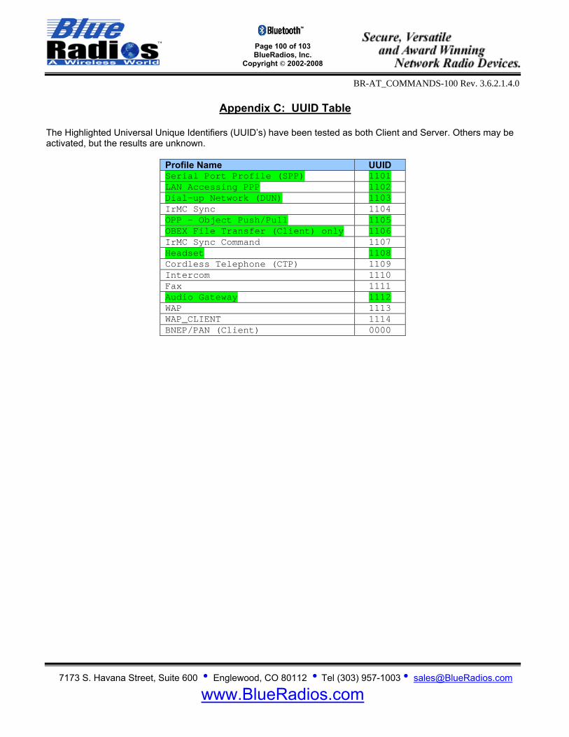
Page 100 of 103 BlueRadios, Inc.
Copyright © 2002-2008
BR-AT_COMMANDS-100 Rev. 3.6.2.1.4.0
7173 S. Havana Street, Suite 600 • Englewood, CO 80112 • Tel (303) 957-1003 • [email protected]
www.BlueRadios.com
Appendix C: UUID Table
The Highlighted Universal Unique Identifiers (UUID’s) have been tested as both Client and Server. Others may be activated, but the results are unknown.
Profile Name UUID Serial Port Profile (SPP) 1101 LAN Accessing PPP 1102 Dial-up Network (DUN) 1103 IrMC Sync 1104 OPP - Object Push/Pull 1105 OBEX File Transfer (Client) only 1106 IrMC Sync Command 1107 Headset 1108 Cordless Telephone (CTP) 1109 Intercom 1110 Fax 1111 Audio Gateway 1112 WAP 1113 WAP_CLIENT 1114 BNEP/PAN (Client) 0000
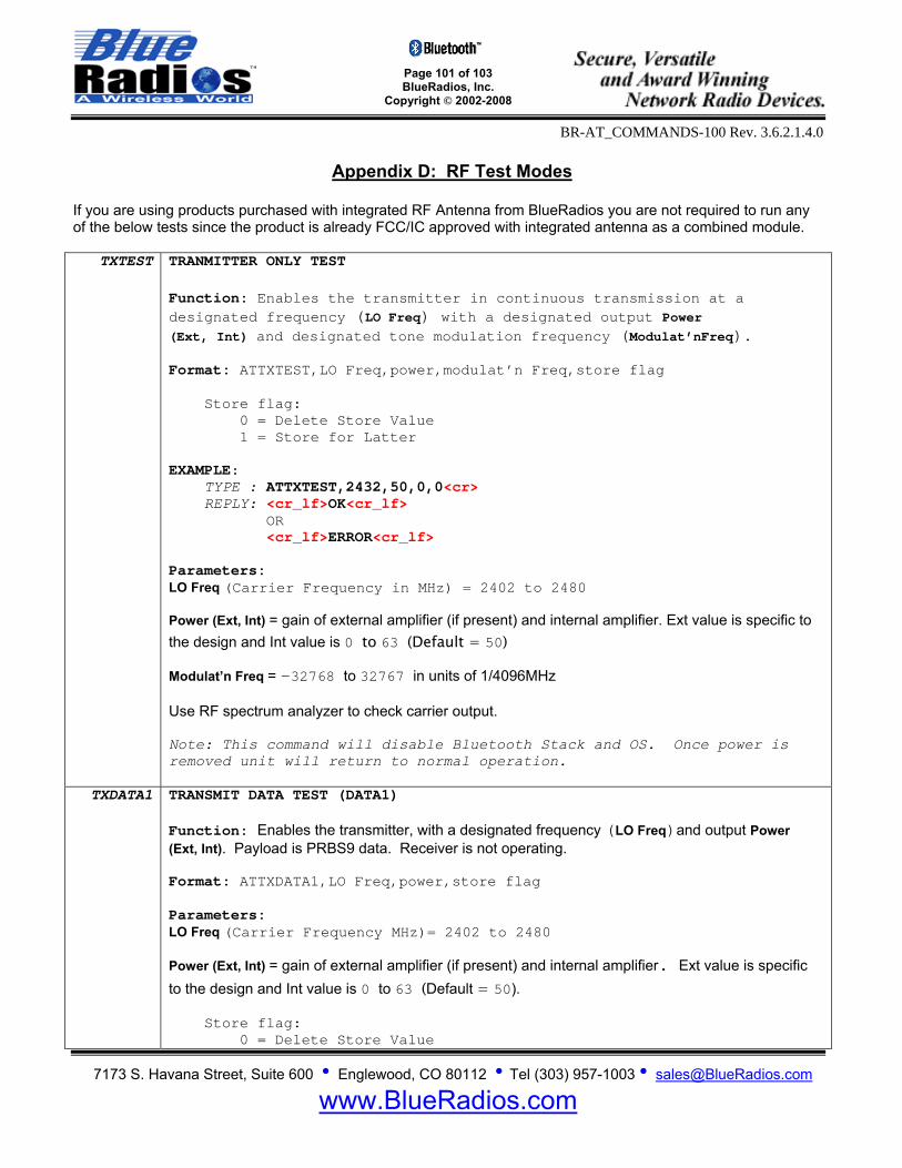
Page 101 of 103 BlueRadios, Inc.
Copyright © 2002-2008
BR-AT_COMMANDS-100 Rev. 3.6.2.1.4.0
7173 S. Havana Street, Suite 600 • Englewood, CO 80112 • Tel (303) 957-1003 • [email protected]
www.BlueRadios.com
Appendix D: RF Test Modes
If you are using products purchased with integrated RF Antenna from BlueRadios you are not required to run any of the below tests since the product is already FCC/IC approved with integrated antenna as a combined module.
TXTEST TRANMITTER ONLY TEST Function: Enables the transmitter in continuous transmission at a designated frequency (LO Freq) with a designated output Power (Ext, Int) and designated tone modulation frequency (Modulat’nFreq). Format: ATTXTEST,LO Freq,power,modulat’n Freq,store flag Store flag: 0 = Delete Store Value 1 = Store for Latter EXAMPLE: TYPE : ATTXTEST,2432,50,0,0<cr> REPLY: <cr_lf>OK<cr_lf> OR <cr_lf>ERROR<cr_lf> Parameters: LO Freq (Carrier Frequency in MHz) = 2402 to 2480 Power (Ext, Int) = gain of external amplifier (if present) and internal amplifier. Ext value is specific to the design and Int value is 0 to 63 (Default = 50) Modulat’n Freq = -32768 to 32767 in units of 1/4096MHz Use RF spectrum analyzer to check carrier output. Note: This command will disable Bluetooth Stack and OS. Once power is removed unit will return to normal operation.
TXDATA1 TRANSMIT DATA TEST (DATA1) Function: Enables the transmitter, with a designated frequency (LO Freq)and output Power (Ext, Int). Payload is PRBS9 data. Receiver is not operating. Format: ATTXDATA1,LO Freq,power,store flag Parameters: LO Freq (Carrier Frequency MHz)= 2402 to 2480 Power (Ext, Int) = gain of external amplifier (if present) and internal amplifier. Ext value is specific to the design and Int value is 0 to 63 (Default = 50). Store flag: 0 = Delete Store Value

Page 102 of 103 BlueRadios, Inc.
Copyright © 2002-2008
BR-AT_COMMANDS-100 Rev. 3.6.2.1.4.0
7173 S. Havana Street, Suite 600 • Englewood, CO 80112 • Tel (303) 957-1003 • [email protected]
www.BlueRadios.com
1 = Store for Latter EXAMPLE: TYPE : ATTXDATA1,2432,50,0<cr> REPLY: <cr_lf>OK<cr_lf> OR <cr_lf>ERROR<cr_lf> Use RF spectrum analyzer to check carrier output. Note: This command will disable Bluetooth Stack and OS. Once power is removed unit will return to normal operation. Read Stored TXDATA Settings Using: ATSI,23
ATTXDATA2 TRANSMIT DATA TEST (DATA2) Function: Enables the transmitter, with a simplified hop sequence designated by Country Code and sets output Power (Ext, Int). Payload is PRBS9 data (default DH1). Receiver is not operating. Format: ATTXDATA2,country code,power,store flag Parameters: Country Code: 0-3 (Default = 0) North America and Europe LO Freq (Carrier Frequency MHz)= 2402 to 2480 Power (Ext, Int) = gain of external amplifier (if present) and internal amplifier. Ext value is specific to the design and Int value is 0 to 63 (Default = 50). Store flag: 0 = Delete Store Value 1 = Store for Latter EXAMPLE: TYPE : ATTXDATA2,0,50,0<cr> REPLY: <cr_lf>OK<cr_lf>
OR <cr_lf>ERROR<cr_lf> Read Stored TXDATA Settings Using: ATSI,23
ATSSW,9 Boot With Stored Test Transmit Values Function: Use this command to store in memory and execute on power up specific RF Test modes. Format: ATSSW,9,<Enable/Disable> Parameters:
Enable/Disable: 0 = nothing 1 = TXDATA1
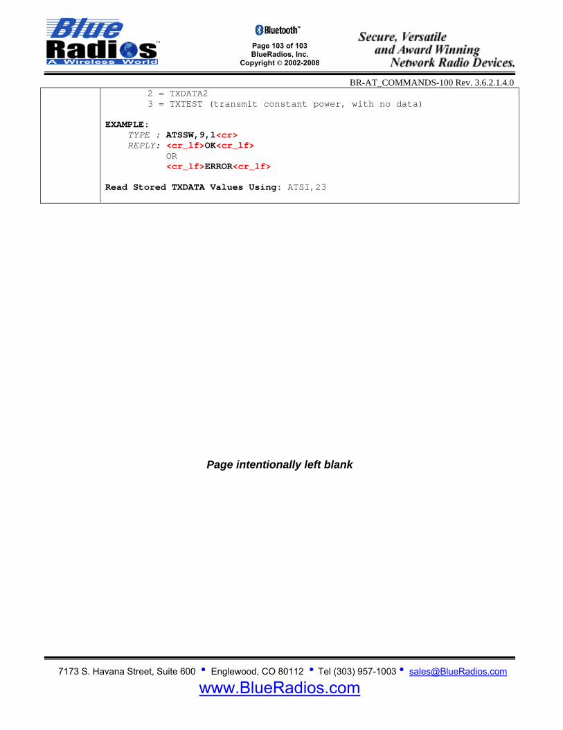
Page 103 of 103 BlueRadios, Inc.
Copyright © 2002-2008
BR-AT_COMMANDS-100 Rev. 3.6.2.1.4.0
7173 S. Havana Street, Suite 600 • Englewood, CO 80112 • Tel (303) 957-1003 • [email protected]
www.BlueRadios.com
2 = TXDATA2 3 = TXTEST (transmit constant power, with no data)
EXAMPLE: TYPE : ATSSW,9,1<cr> REPLY: <cr_lf>OK<cr_lf> OR <cr_lf>ERROR<cr_lf> Read Stored TXDATA Values Using: ATSI,23
Page intentionally left blank