Blue Book Derail - Western-Cullen-Hayes Incwch.com/pdf/wchdrlhndbk.pdf · plished by guiding the...
33
DERAILS Installation Inspection Maintenance SERVING THE INDUSTRY SINCE 1903 WESTERN-CULLEN-HAYES, INC. 2700 W. 36TH Place, Chicago, IL. 60632 (773) 254-9600 FAX (773) 254-1110 WESTERN-CULLEN-HAYES, INC. 120 N. 3rd St., P.O. Box 756, Richmond, IN 47374 (765) 962-0526 FAX (765) 966-5374
Transcript of Blue Book Derail - Western-Cullen-Hayes Incwch.com/pdf/wchdrlhndbk.pdf · plished by guiding the...
DERAILS
Installation
Inspection
Maintenance
SERVING THE INDUSTRY SINCE 1903
WESTERN-CULLEN-HAYES, INC. 2700 W. 36TH Place, Chicago, IL. 60632 (773) 254-9600 FAX (773) 254-1110
WESTERN-CULLEN-HAYES, INC.120 N. 3rd St., P.O. Box 756, Richmond, IN 47374(765) 962-0526 FAX (765) 966-5374

-1-
INDEX 1.0 Purpose of a Hayes Derail 2.0 Models of Hayes Derails 2.1 Sliding Derail, HB Series 2.2 Hinged Derail, EB Series 2.3 Portable Derail, LPTS 2.5 Field Side Derail, KA 3.0 Preparation for Installing
Hayes Derails 3.1 Site Requirements 3.2 Selecting Correct Size 3.3 Selecting Right or Left Hand 4.0 Installing HB Sliding Derails 4.1 Locating the Derail 4.2 Positioning the Derail Relative to
The Rail 4.3 Putting the Derail In Track 4.4 Data Concerning Adjustment of
Vertical Height 4.5 Making the Derail A Fixed Part
of The Track 4.6 Operating or Indicating Connections
To Derail 5.0 Installing EB Hinge Derails 5.1 Requirements of Location, Size &
Hand 5.2 Setting the Derail in Track 6.0 Installing Hayes Portable TS Derail 7.0 Installing Hayes Field Side KA Derail 8.0 Derail Operating Stands 8.1 Two-Tie Operating Stand 8.2 One-Tie Operating Stand 8.3 Close Coupled Operating Stand 8.4 High Rise Operating Stand 8.5 Installing Operating Stand With
Sliding Derails 9.0 Derail Target Stand 9.1 Target Stand for HB or EB Derails 9.2 Operation of Target Stand 9.3 Installing Target Stand10.0 WCH Wheel Crowder10.1 Crowder in Track with EB Hinge Derail10.2 Crowder in Track with HB Sliding Derail10.3 Illustrations of Correct & Incorrect
Crowder Installations11.0 Inspection and Maintenance of Permanently
Installed Model HB & EB Series Derails11.1 Inspection Data Required11.2 Explanation of Inspection Questions12.0 In Conclusion

-2-
-3-
1.0 PURPOSE OF A HAYES® DERAILA Hayes® Derail is a device designed to limit movementof free rolling uncontrolled railroad cars. This is accom-plished by guiding the flange of a car wheel up and overthe rail head and deflecting it laterally to drop the wheelclear of the rail on the field side (outside) of the rails.Movement of the car is halted by the wheels lodging inthe tie cribbing and ballast.
2.0 MODELS OF HAYES® DERAILS
2.1 SLIDING, See Figure 1
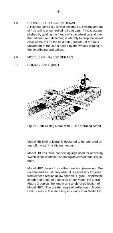
Figure 1-HB Sliding Derail with 2 Tie Operating Stand
Model HB Sliding Derail is designed to be operated onand off the rail in a sliding motion.
Model HB has three connecting lugs used for attachingswitch circuit controller, operating devices or other equip-ment.
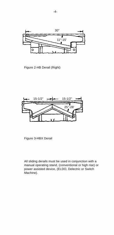
Model HBX derails from either direction (two-way). Werecommend its use only when it is necessary to derailfrom either direction at low speeds. Figure 2 depicts thelength and angle of deflection of our Model HB Derail.Figure 3 depicts the length and angle of deflection ofModel HBX. The greater angle of deflection in ModelHBX results in less derailing efficiency than Model HB.
-4-
Figure 3-HBX Derail
All sliding derails must be used in conjunction with amanual operating stand, (conventional or high rise) orpower assisted device, (ELDO, Delectric or SwitchMachine).
Figure 2-HB Derail (Right)
30"
11°-15'
15-1/2" 15-1/2"
25°-28'
-5-
2.2 HINGED, See Figure 4
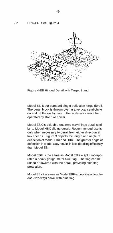
Figure 4-EB Hinged Derail with Target Stand
Model EB is our standard single deflection hinge derail.The derail block is thrown over in a vertical semi-circleon and off the rail by hand. Hinge derails cannot beoperated by stand or power.
Model EBX is a double-end (two-way) hinge derail simi-lar to Model HBX sliding derail. Recommended use isonly when necessary to derail from either direction atlow speeds. Figure 3 depicts the length and angle ofdeflection of Model EBX and HBX. The greater angle ofdeflection in Model EBX results in less derailing efficiencythan Model EB.
Model EBF is the same as Model EB except it incorpo-rates a heavy gauge metal blue flag. The flag can beraised or lowered with the derail, providing blue flagprotection.
Model EBXF is same as Model EBF except it is a double-end (two-way) derail with blue flag.
-6-
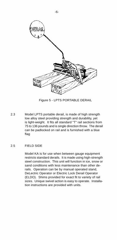
2.3 Model LPTS portable derail, is made of high strengthlow alloy steel providing strength and durability, yetis light-weight. It fits all standard "T" rail sections from75 to 136 pounds and is single direction throw. The derailcan be padlocked on rail and is furnished with a blueflag
2.5 FIELD SIDE
Model KA is for use when between gauge equipmentrestricts standard derails. It is made using high-strengthsteel construction. This unit will function in ice, snow orsand conditions with less maintenance than other de-rails. Operation can be by manual operated stand,DeLectric Operator or Electric Lock Derail Operator(ELDO). Shims provided for exact fit to variety of railsizes. Unique swivel action is easy to operate. Installa-tion instructions are provided with units.
Figure 5 - LPTS PORTABLE DERAIL
Provide a right hand or a left hand derail as the directionof derailing requires, unless a double-end derail is to beused. The requirements for the correct installation of aHayes Derail are:
1. The track must be in good condition at the two ties where the derail is to be installed. The ties should be sound and well tamped up, are at right angles to the rail and must hold the rail firmly to the gauge.
2. The derail must be made a fixed part of the track.
3. If rail tie plates are used, they must be cropped even with the base of the rail; they should never extend under the derail.
4. Drainage must be adequate to prevent water from collecting around the derail. While water will not affect the function, ice can hinder the movement of the derail.
3.2 Selecting Correct SizeA Hayes Derail must be the correct size for the rail. Thesize number of the derail is stamped on the nameplate.This number indicates the distance in inches, from thetop of the rail to the surface on which the derail will besecured.
-7-
3.0 PREPARATION FOR INSTALLING HAYES DERAILS
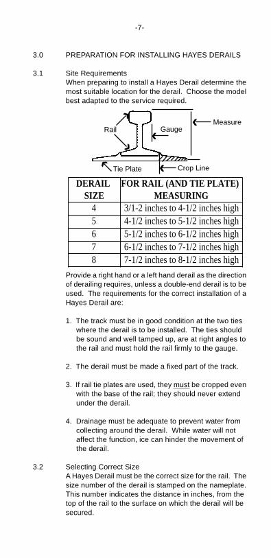
3.1 Site RequirementsWhen preparing to install a Hayes Derail determine themost suitable location for the derail. Choose the modelbest adapted to the service required.
DERAIL SIZE
FOR RAIL (AND TIE PLATE) MEASURING
4 3/1-2 inches to 4-1/2 inches high5 4-1/2 inches to 5-1/2 inches high6 5-1/2 inches to 6-1/2 inches high7 6-1/2 inches to 7-1/2 inches high8 7-1/2 inches to 8-1/2 inches high
Rail
Tie Plate
GaugeMeasure
Crop Line
‹‹
‹
‹
‹
‹
<
Direction oftravel
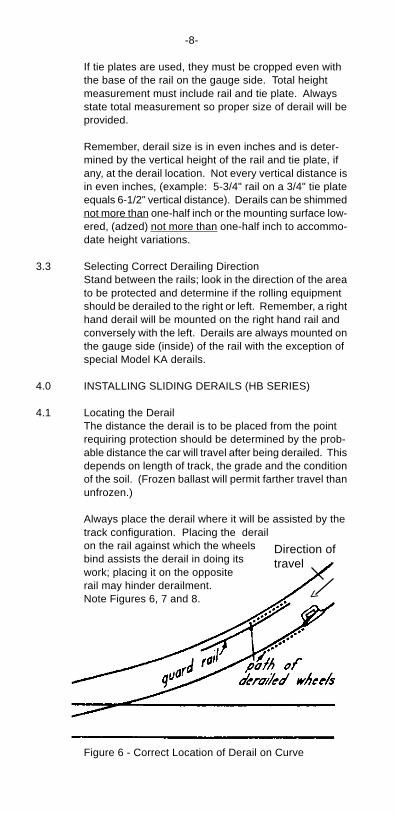
Figure 6 - Correct Location of Derail on Curve
-8-
If tie plates are used, they must be cropped even withthe base of the rail on the gauge side. Total heightmeasurement must include rail and tie plate. Alwaysstate total measurement so proper size of derail will beprovided.
Remember, derail size is in even inches and is deter-mined by the vertical height of the rail and tie plate, ifany, at the derail location. Not every vertical distance isin even inches, (example: 5-3/4" rail on a 3/4" tie plateequals 6-1/2" vertical distance). Derails can be shimmednot more than one-half inch or the mounting surface low-ered, (adzed) not more than one-half inch to accommo-date height variations.
3.3 Selecting Correct Derailing DirectionStand between the rails; look in the direction of the areato be protected and determine if the rolling equipmentshould be derailed to the right or left. Remember, a righthand derail will be mounted on the right hand rail andconversely with the left. Derails are always mounted onthe gauge side (inside) of the rail with the exception ofspecial Model KA derails.
4.0 INSTALLING SLIDING DERAILS (HB SERIES)
4.1 Locating the DerailThe distance the derail is to be placed from the pointrequiring protection should be determined by the prob-able distance the car will travel after being derailed. Thisdepends on length of track, the grade and the conditionof the soil. (Frozen ballast will permit farther travel thanunfrozen.)
Always place the derail where it will be assisted by thetrack configuration. Placing the derailon the rail against which the wheelsbind assists the derail in doing itswork; placing it on the oppositerail may hinder derailment.Note Figures 6, 7 and 8.
-9-
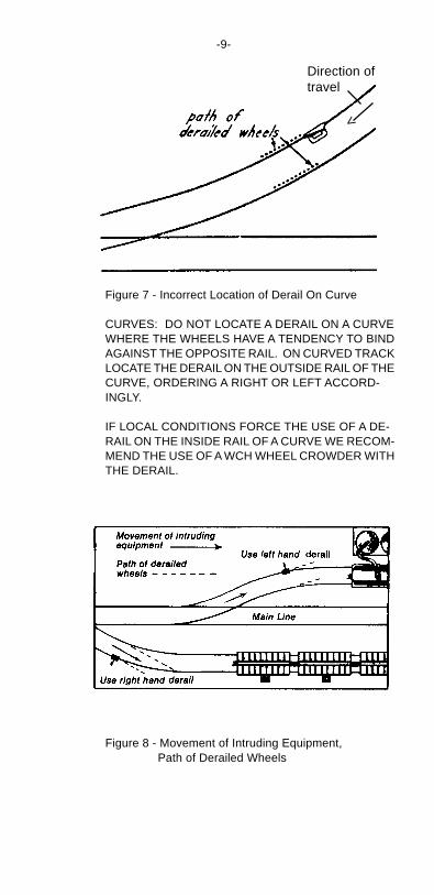
Figure 7 - Incorrect Location of Derail On Curve
CURVES: DO NOT LOCATE A DERAIL ON A CURVEWHERE THE WHEELS HAVE A TENDENCY TO BINDAGAINST THE OPPOSITE RAIL. ON CURVED TRACKLOCATE THE DERAIL ON THE OUTSIDE RAIL OF THECURVE, ORDERING A RIGHT OR LEFT ACCORD-INGLY.
IF LOCAL CONDITIONS FORCE THE USE OF A DE-RAIL ON THE INSIDE RAIL OF A CURVE WE RECOM-MEND THE USE OF A WCH WHEEL CROWDER WITHTHE DERAIL.
Figure 8 - Movement of Intruding Equipment,Path of Derailed Wheels
<
Direction oftravel
-10-
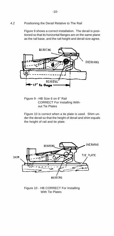
4.2 Positioning the Derail Relative to The Rail
Figure 9 shows a correct installation. The derail is posi-tioned so that its horizontal flanges are on the same planeas the rail base, and the rail height and derail size agree.
Figure 10 - HB CORRECT For Installing With Tie Plates
Figure 9 - HB Size 6 on 6" RailCORRECT For Installing With-out Tie Plates
Figure 10 is correct when a tie plate is used. Shim un-der the derail so that the height of derail and shim equalsthe height of rail and tie plate.
-11-
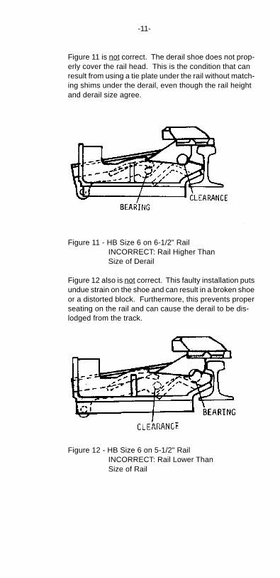
Figure 11 is not correct. The derail shoe does not prop-erly cover the rail head. This is the condition that canresult from using a tie plate under the rail without match-ing shims under the derail, even though the rail heightand derail size agree.
Figure 11 - HB Size 6 on 6-1/2" Rail INCORRECT: Rail Higher Than Size of Derail
Figure 12 also is not correct. This faulty installation putsundue strain on the shoe and can result in a broken shoeor a distorted block. Furthermore, this prevents properseating on the rail and can cause the derail to be dis-lodged from the track.
Figure 12 - HB Size 6 on 5-1/2" Rail INCORRECT: Rail Lower Than Size of Rail
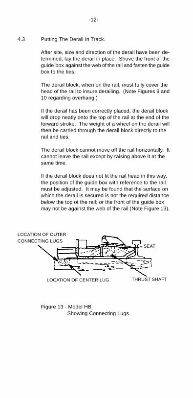
Figure 13 - Model HB Showing Connecting Lugs
-12-
4.3 Putting The Derail In Track.
After site, size and direction of the derail have been de-termined, lay the derail in place. Shove the front of theguide box against the web of the rail and fasten the guidebox to the ties.
The derail block, when on the rail, must fully cover thehead of the rail to insure derailing. (Note Figures 9 and10 regarding overhang.)
If the derail has been correctly placed, the derail blockwill drop neatly onto the top of the rail at the end of theforward stroke. The weight of a wheel on the derail willthen be carried through the derail block directly to therail and ties.
The derail block cannot move off the rail horizontally. Itcannot leave the rail except by raising above it at thesame time.
If the derail block does not fit the rail head in this way,the position of the guide box with reference to the railmust be adjusted. It may be found that the surface onwhich the derail is secured is not the required distancebelow the top ot the rail; or the front of the guide boxmay not be against the web of the rail (Note Figure 13).
SEAT
THRUST SHAFT
LOCATION OF OUTERCONNECTING LUGS
LOCATION OF CENTER LUG
-13-
4.4 Data Concerning Adjustment of Vertical Height
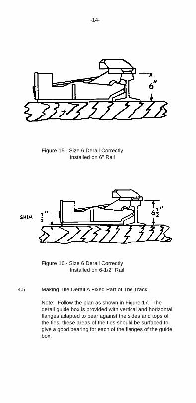
Example: You have a Size 6 Derail (from nameplate).VERTICAL DISTANCE is 6-1/2". (5-3/4" high rail on a3/4" tie plate). Derail, sitting on ties, will be 1/2" too low.You may either A) Shim up the derail 1/2" with steelshims, or B) Remove the tie plates under the rail andadz the ties 1/4" under the Derail. Either method willmake the distance from the TOP OF RAIL TO TOP OFTIE (where the derail sits) the same number of inchesas size number of Derail. THIS IS A MUST.See Figure 16.
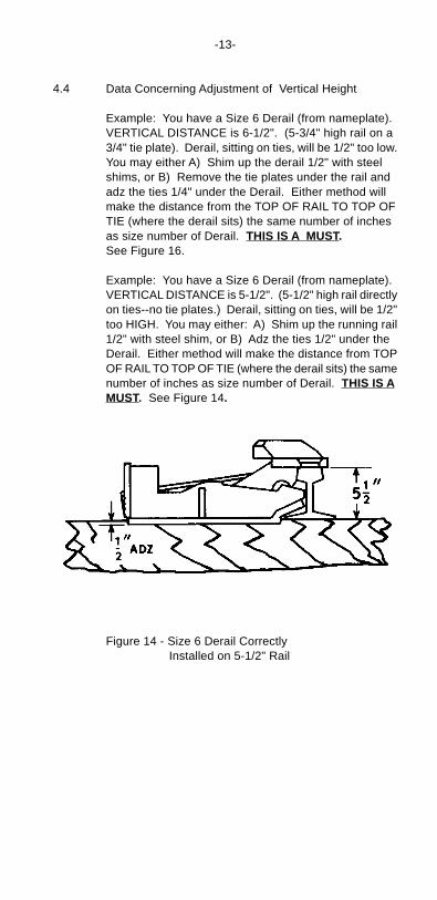
Example: You have a Size 6 Derail (from nameplate).VERTICAL DISTANCE is 5-1/2". (5-1/2" high rail directlyon ties--no tie plates.) Derail, sitting on ties, will be 1/2"too HIGH. You may either: A) Shim up the running rail1/2" with steel shim, or B) Adz the ties 1/2" under theDerail. Either method will make the distance from TOPOF RAIL TO TOP OF TIE (where the derail sits) the samenumber of inches as size number of Derail. THIS IS AMUST. See Figure 14.
Figure 14 - Size 6 Derail Correctly Installed on 5-1/2" Rail
-14-
Figure 15 - Size 6 Derail Correctly Installed on 6" Rail
Figure 16 - Size 6 Derail Correctly Installed on 6-1/2" Rail
4.5 Making The Derail A Fixed Part of The Track
Note: Follow the plan as shown in Figure 17. Thederail guide box is provided with vertical and horizontalflanges adapted to bear against the sides and tops ofthe ties; these areas of the ties should be surfaced togive a good bearing for each of the flanges of the guidebox.
-15-
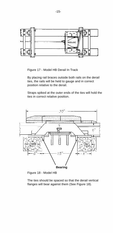
Figure 17 - Model HB Derail In Track
By placing rail braces outside both rails on the derailties, the rails will be held to gauge and in correctposition relative to the derail.
Straps spiked at the outer ends of the ties will hold theties in correct relative position.
Bearing
Figure 18 - Model HB
The ties should be spaced so that the derail verticalflanges will bear against them (See Figure 18).
-16-
The horizontal flanges have holes 31/32" diameter.These will accommodate 5/8" square track spikes or lagscrews up to 15/16" diameter. All of these openingsshould be used so that the derail may be firmly afixed tothe ties.
4.6 Operating or Indicating Connections to Derail
Models HB and HBX have three connecting lugs, 3/4"thick with 57/64" dia. holes, with one lug being offset.(See Figure 18) Operating and locking connectionsshould be placed at right angles to the rail and in directline with the movement of the derail block.
5.0 INSTALLING HINGE DERAILS(EB SERIES)
5.1 Basic instruction for HB Derails also apply to EB SeriesDerails, follow the previously mentioned requirementsof location, size and direction of throw.
5.2 Set the derail in track with the derailing block down flaton the rail and position so that the vertical surface underthe derail block just touches the gauge side of runningrail.
-17-
Ties should be in good condition and spaced (12")to bear against the vertical flanges of the derail guidebox. The ties should be tamped thoroughly to provide agood bearing under the running rail. The derail shouldbe secured to the ties with six spikes or lag screws fullydriven.
The derail block should come down flat onto the top ofthe rail; it will do this if the derail is correctly placed.Also, the block should fully cover the head of the rail toinsure derailing. The shoe is designed for a 1/2" over-hang with 3" head width, smaller width heads shouldhave correspondingly increased overhang.
6.0 INSTALLING HAYES PORTABLE DERAIL MODEL TS
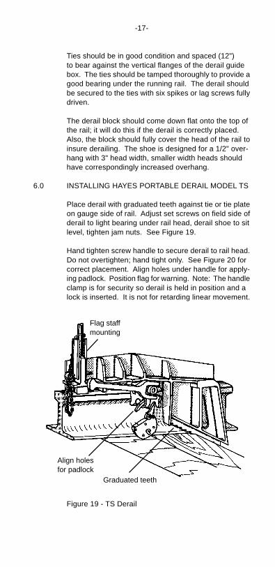
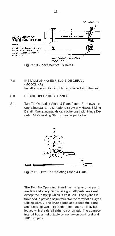
Place derail with graduated teeth against tie or tie plateon gauge side of rail. Adjust set screws on field side ofderail to light bearing under rail head, derail shoe to sitlevel, tighten jam nuts. See Figure 19.
Hand tighten screw handle to secure derail to rail head.Do not overtighten; hand tight only. See Figure 20 forcorrect placement. Align holes under handle for apply-ing padlock. Position flag for warning. Note: The handleclamp is for security so derail is held in position and alock is inserted. It is not for retarding linear movement.
Flag staffmounting
Align holesfor padlock
Graduated teeth
Figure 19 - TS Derail
-18-
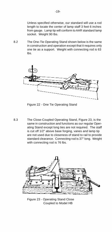
Figure 21 - Two Tie Operating Stand & Parts
The Two-Tie Operating Stand has no gears; the partsare few and everything is in sight. All parts are steelexcept the lamp tip which is cast iron. The eyebolt isthreaded to provide adjustment for the throw of a HayesSliding Derail. The lever opens and closes the derailand turns the vanes through a right angle; it may belocked with the derail either on or off rail. The connect-ing rod has an adjustable screw jaw on each end and7/8" turn pins.
Figure 20 - Placement of TS Derail
7.0 INSTALLING HAYES FIELD SIDE DERAIL(MODEL KA)Install according to instructions provided with the unit.
8.0 DERAIL OPERATING STANDS
8.1 Two-Tie Operating Stand & Parts Figure 21 shows theoperating stand. It is made to throw any Hayes SlidingDerail. Operating stands cannot be used with Hinge De-rails. All Operating Stands can be padlocked.
-19-
Unless specified otherwise, our standard will use a rodlength to locate the center of lamp staff 3 feet 6 inchesfrom gauge. Lamp tip will conform to AAR standard lampsocket. Weight 90 lbs.
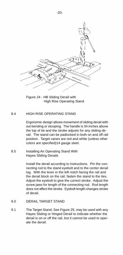
8.2 The One-Tie Operating Stand shown below is the samein construction and operation except that it requires onlyone tie as a support. Weight with connecting rod is 63lbs.
Figure 23 - Operating Stand Close Coupled to Model HB
Figure 22 - One Tie Operating Stand
8.3 The Close-Coupled Operating Stand, Figure 23, is thesame in construction and functions as our regular Oper-ating Stand except long ties are not required. The staffis cut off 1/2" above base forging, vanes and lamp tipare not used due to closeness of stand to rail to providestandard clearance. Connecting rod is 37" long. Weightwith connecting rod is 76 lbs.
-20-
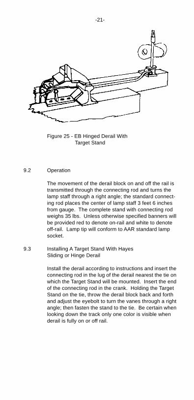
Figure 24 - HB Sliding Derail with High Rise Operating Stand
8.4 HIGH RISE OPERATING STAND
Ergonomic design allows movement of sliding derail without bending or stooping. The handle is 34 inches abovethe top of tie and the stroke adjusts for any sliding de-rail. The stand can be padlocked in both on and off railposition. Target vanes are red and white (unless othercolors are specified)14 gauge steel.
8.5 Installing An Operating Stand WithHayes Sliding Derails
Install the derail according to instructions. Pin the con-necting rod to the stand eyebolt and to the center deraillug. With the lever in the left notch facing the rail andthe derail block on the rail, fasten the stand to the ties.Adjust the eyebolt to give the correct stroke. Adjust thescrew jaws for length of the connecting rod. Rod lengthdoes not affect the stroke. Eyebolt length changes strokeof derail.
9.0 DERAIL TARGET STAND
9.1 The Target Stand, See Figure 25, may be used with anyHayes Sliding or Hinged Derail to indicate whether thederail is on or off the rail, but it cannot be used to oper-ate the derail.
-21-
9.2 Operation
The movement of the derail block on and off the rail istransmitted through the connecting rod and turns thelamp staff through a right angle; the standard connect-ing rod places the center of lamp staff 3 feet 6 inchesfrom gauge. The complete stand with connecting rodweighs 35 lbs. Unless otherwise specified banners willbe provided red to denote on-rail and white to denoteoff-rail. Lamp tip will conform to AAR standard lampsocket.
9.3 Installing A Target Stand With HayesSliding or Hinge Derail
Install the derail according to instructions and insert theconnecting rod in the lug of the derail nearest the tie onwhich the Target Stand will be mounted. Insert the endof the connecting rod in the crank. Holding the TargetStand on the tie, throw the derail block back and forthand adjust the eyebolt to turn the vanes through a rightangle; then fasten the stand to the tie. Be certain whenlooking down the track only one color is visible whenderail is fully on or off rail.
Figure 25 - EB Hinged Derail With Target Stand
-22-
10.0 WESTERN-CULLEN-HAYES WHEEL CROWDER(Patented)
The Wheel Crowder is a device designed to assist thefunctioning of derails under unusual conditions such aslocation on inside rail of curves and on descendinggrades. It is designed for use with our Model HB andEB Derails. When used with Model HB the derail andWheel Crowder may be moved into or out of the work-ing position by a hand operated stand or Delectric derailoperator subject to remote or local control. When usedwith Model EB Hinge Derail, the Wheel Crowder is movedinto or out of the working position when the derail blockis thrown over in a vertical semi-circle on or off the railby hand.
A Wheel Crowder consists of two pieces; a completeCrowder and one rod which attaches to the derail. Be-fore installing, read nameplate on Crowder to be sureCrowder is correct for derail being used. A crowder forhinge derails will not work with sliding derails and aCrowder for sliding derails will not work with hingederails.
Nameplate also indicates size and right or left hand. Sizemust correspond to size of derail being used. Also, aright hand Wheel Crowder must be used with a righthand derail; conversely with the left. The Wheel Crowdercannot be used with A double-end derail (two-way).Regarding size, use same instructions as to determin-ing size given with the derail.
10.1 PUTTING THE WHEEL CROWDER IN TRACK WHENUSED WITH MODEL EB HINGE DERAIL
1. Place Crowder against gauge side of rail opposite derail. Be certain ties are at right angles to rail.
2. The vertical flanges on base of Wheel Crowder are same as derail, maintaining straight, parallel ties for correct installation.
-23-
3. Two bolt holes are provided, one at each end of Crowder, drill holes in rail to accommodate the bolts and tighten Crowder to web of rail. Use set screws at web to maintain proper point contact with rail. Use spikes or lag screws to securely hold the crowder in position.
4. With the derail and Crowder secured in place, attach connecting rod in the left hand lug of the derail, insert and spread cotter key.
5. Fit the connecting rod to the Crowder, adjust the turnbuckle to fit snug when derail is in the on-rail position and the crowder point is snug against gauge side. Insert pin and spread the cotter key.
6. Test your installation by positioning the derail to the off-rail position with very little physical effort. The Crowder should be in the non- derailing position.
7. Do not install a Wheel Crowder with a double- end derail (EBX, EBXF); use only a right or left hand derail. A Crowder accepts a wheel from one direction only, angles of deflection do not correspond with double-end derailers.
8. All moving parts should be well lubricated to insure ease of movement. Graphite should be used on sliding surfaces.
10.2 PUTTING THE WHEEL CROWDER IN TRACK WHENUSED WITH MODEL HB SLIDING DERAIL
1. Place the Wheel Crowder against gage side of rail opposite to which derail is located. Be certain ties are at right angles to rail.
2. The vertical flanges on base of Wheel Crowder are same as derail, maintaining straight, parallel ties for correct installation.
-24-
3. Two bolt holes are provided, one at each end of Crowder. Drill holes in rail to accommodate the bolts and tighten Crowder to web of rail. Use set screws at web to maintain proper point contact with rail. Use spikes or lag screws to securely hold the Crowder in position.
4. With derail and Crowder secured in place, first attach the connecting rod to the left lug on the derail, then connect the opposite end of the connecting rod with the turn-buckle into the reversing crank mechanism on the base of the Crowder.
5. Attach the connecting rod from the manual or electric operating mechanism that places Derail and Crowder in the on-rail or off-rail position to the turn-buckle on the operating stand, and the opposite end into the right hand lug on the Derail. Insert and spread all cotter keys in the connecting rods.
6. Do not install Wheel Crowder with double-end derail (HBX), use only right or left hand derails. A Crowder accepts a wheel from one direction only, angles of deflection do not correspond.
7. All moving parts should be well lubricated to insure ease of movement. Graphite should be used on all sliding surfaces.
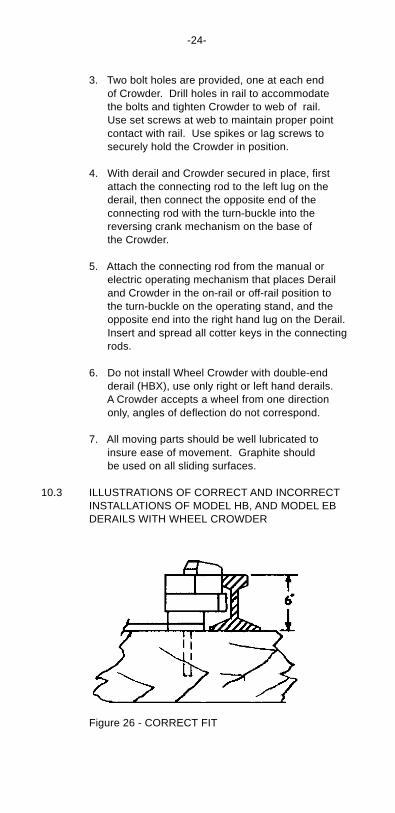
10.3 ILLUSTRATIONS OF CORRECT AND INCORRECTINSTALLATIONS OF MODEL HB, AND MODEL EBDERAILS WITH WHEEL CROWDER
Figure 26 - CORRECT FIT
-25-
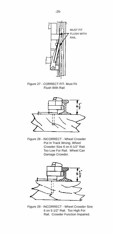
Figure 29 - INCORRECT - Wheel Crowder Size 6 on 5-1/2" Rail. Too High For Rail. Crowder Function Impaired.
Figure 27 - CORRECT FIT- Must Fit Flush With Rail
Figure 28 - INCORRECT - Wheel Crowder Put In Track Wrong, Wheel Crowder Size 6 on 6-1/2" Rail. Too Low For Rail. Wheel Can Damage Crowder.
MUST FITFLUSH WITHRAIL
-26-
11.0 INSPECTION AND MAINTENANCE OFPERMANENTLY INSTALLED DERAILSMODEL HB AND EB SERIES
11.1 Inspection Data RequiredDerails should be given the same inspection and main-tenance that other track and signal devices receive.
When anything happens at a derail which seems to re-flect on the efficiency of the installation, the conditionsat the derail should be examined and a record made bywriting down the answers to the following questions:
1. Model and size of derail.
2. Actual height of rail, actual width of head of rail.
3. Is the derail on the outside rail or inside rail of a curve? About what degree is the curve? Is it on straight track?
4. What is the condition of the ties?
5. What is gauge of track at derail?
6. How far is the guide box away from the web of the rail?
7. What is the vertical distance from the top of the rail to the surface on which the derail is secured?
8. Are the ties and operating connections at right angles to the rail?
9 How is the derail fastened to the ties and are all holes in the horizontal tie flanges of the guide box used?
10. How many rail braces and tie plates are used on the derail ties?
11. Is the rail held firmly to the ties at the derail?
12. Are the ties well tamped up to a firm bearing?
-27-
13. Are the derail ties strapped together?
14. Do the bottom vertical flanges of the derail guide box bear against the sides of the ties?
15. Does the derail block at the heel end fully cover the head of the rail?
16. Has the derail been damaged in any way and if so, what result will it have on the function of the derail?
17. How is the derail operated? Is it well lubricated?
18. Give any other essential facts bear- ing on the location or condition of the derail.
If the analysis of an inspection as outlinedabove does not straighten out the matter,please send the record to us and we willbe glad to assist you.
11.2 Explanation of Inspection Questions
A better understanding of the inspections can be gainedif you read the explanation of each item listed here:
1. The model symbol and size number of the HB and EB Series Derails will be found on the nameplate. On derails installed previous to 1948, this will be found on the castings. The size number indicates the distance in inches down from the top of the rail to the surface on which the derail must be secured.
2. All derails shipped since 1949 (Models HB, HBP, HBX, HBXP and EB, EBX, and EBF, EBXF are suitable for rail up to 3" wide, but many models shipped previous to 1949 are for rail heads not more than 2-1/2" wide. These are cast derails Model A, AP, G, GP and D and in the interest of safe operations these models should be confined to light rail or they should be replaced with derails of the HB and EB series.
-28-
3. We do not recommend that a derail be placed on the inside rail of a curve. If local conditions force the use of a derail on the inside rail of a curve, we recommend the use of a WCH Wheel Crowder with a derail.
4. The two ties on which the derail is placed should be sound to insure holding the derail in position when a wheel encounters it.
5. If the gauge is wide, the flange of a wheel en- countering the derail block may not enter the flange groove as it should. Proper widening on a curve is allowable if the derail is placed as shown, Figure 7, Point 4.1.
6. This refers to derails of the sliding type where the front of the guide box should be against the web of the rail. The exception would be with a rail head unusually wide compared with the thickness of the web; here it may be nec- essary to keep the guide box slightly away from the web of the rail so as to permit the derail block to come down flat onto the rail. This includes old style cast derails previous to 1948, Models G, J, H, HP, HX, HXP and the current all-steel derails Model HB, HBP, HBX, and HBXP. The derail block will then be held in place by its bearing against the rail and the seats in the guide box. The vertical front surface of the derail block in the hinge derail should be against the gauge of the rail; this in- cludes cast hinge derails old style Models E, and EX and current Models EB, EBX and EBF.
7. The vertical distance from the top of the rail to the surface on which the derail is secured should be four inches with a size 4 derail, it should be five inches with a size 5 derail, it should be six inches with a size 6 derail, it should be seven inches with a size 7 derail. THIS IS AN ESSENTIAL REQUIREMENT.
-29-
If the derail is high the block will be held above the rail and the weight of a wheel striking it will not be carried direct to the rail and the derail may be damaged. If the derail is low the block will not lie flat on the rail and against the locking seats of the guide box. Place a straight edge across both rails and measure down at all four corners of the hori- zontal tie flanges of the guide box, measure to the under side of the tie flange which is the surface on which the derail is secured.
8. The ties should be at right angles to the rail to hold the derail in correct position. The operating con- nections should be at right angles to the rail so as to be in line with the movement of the derail block.
9. The guide box should be securely fastened to the ties by means of bolts, lag screws or spikes with the proper number inserted in bolt holes whether it is a derail of the HB or EB Series. The derail will then be held to its work.
10. The use of four rail braces or shoulder tie plates on the derail ties insures holding the rails in correct position, See Figure 9, Point 4.2.
11. The rail should be held firmly to the ties at the de- rail. This is just as essential as making the derail a fixed part of the track.
12. The ties should be tamped up to a firm bearing to hold the derail in correct position relative to the rail.
13. Strapping the derail ties together increases the stability of the installation.
14. The sides of the ties should bear against the verti- cal flanges on the guide box to take the thrust when a wheel strikes the derail.
-30-
15. It is essential that the derail block at the heel end fully covers the head of the rail and is held in that position by the seats in the guide box. If it does not, the position of the guide box relative to the rail should be examined. Or there may be insuffi- cient stroke in the operating mechanism. If the derail block at its heel end does not fully cover the head of the rail, a wheel flange may catch on top of the rail after sliding off the derail block.
16. Long experience proves that a Hayes Derail, if properly installed, will take care of repeated de- railments without being damaged unless it is struck when partly thrown or otherwise misused. A description of any wheel marks on the derail should be given.
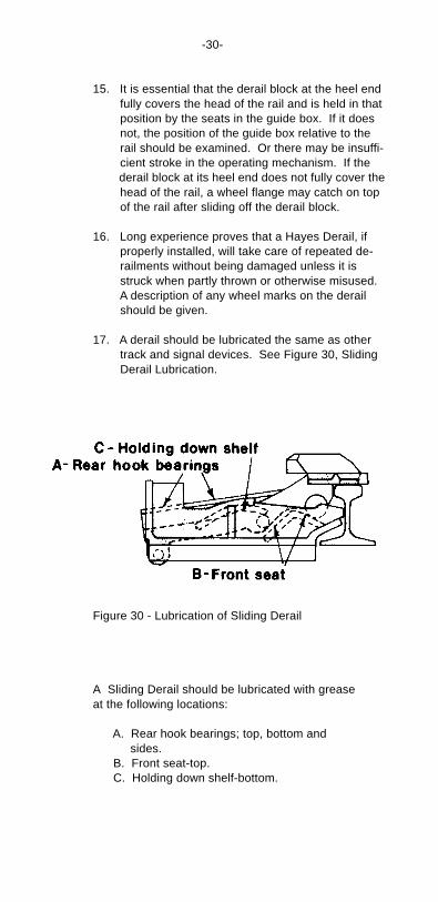
17. A derail should be lubricated the same as other track and signal devices. See Figure 30, Sliding Derail Lubrication.
Figure 30 - Lubrication of Sliding Derail
A Sliding Derail should be lubricated with greaseat the following locations:
A. Rear hook bearings; top, bottom and sides. B. Front seat-top. C. Holding down shelf-bottom.
-31-
18. If the inspection is made as the result of any particular occurrence at the derail, a full descrip- tion should be given.
12.0 IN CONCLUSION
Changes brought about by laying heavy rail in place oflight rail without upgrading the derail creates an unsafecondition. Derails not suitable for use on heavy rail areold-style Models A, G, GP, J and D. These are casttype derails and were made to cover rail heads not morethan 2-1/2" wide. Current derails of the HB and EB se-ries provide a 1/2" overhang of the derailing shoe be-yond a 3" wide rail head.
Please ask us for any assistance you may need withyour derails. We make it our business to help you getthe best results from every Hayes Derail you have intrack.
HAYES PLANT (Factory)Western-Cullen-Hayes, Inc.120 North 3rd St.P. O. Box 756Richmond, Indiana 47374(765) 962-0526 • Fax (765) 966-5374
or GENERAL OFFICEWestern-Cullen-Hayes, Inc.2700 West 36th PlaceChicago, Illinois 60632(773) 254-9600 • Fax (773) 254-1110
Copyright - Not To Be Reproduced Without Permission of thePublisher.Western-Cullen-Hayes, Inc. 1/1998.

-32-
NOTES