Bloch-mode analysis for retrieving effective parameters of ... · PHYSICAL REVIEW B 86, 035127...
10
PHYSICAL REVIEW B 86, 035127 (2012) Bloch-mode analysis for retrieving effective parameters of metamaterials Andrei Andryieuski, 1,* Sangwoo Ha, 2 Andrey A. Sukhorukov, 2 Yuri S. Kivshar, 2 and Andrei V. Lavrinenko 1 1 DTU Fotonik–Department of Photonics Engineering, Technical University of Denmark, Ørsteds pl. 343, DK-2800 Kongens Lyngby, Denmark 2 Nonlinear Physics Centre and Centre for Ultrahigh-bandwidth Devices for Optical Systems (CUDOS), Research School of Physics and Engineering, Australian National University, Canberra, ACT 0200, Australia (Received 10 November 2010; revised manuscript received 29 June 2012; published 18 July 2012) We introduce an approach for retrieving effective parameters of metamaterials based on the Bloch-mode analysis of quasiperiodic composite structures. We demonstrate that, in the case of single-mode propagation, a complex effective refractive index can be assigned to the structure, being restored by our method with a high accuracy. We employ both surface and volume averaging of the electromagnetic fields of the dominating (fundamental) Bloch modes to determine the Bloch and wave impedances, respectively. We discuss how this method works for several characteristic examples, and demonstrate that this approach can be useful for retrieval of both material and wave effective parameters of a broad range of metamaterials. DOI: 10.1103/PhysRevB.86.035127 PACS number(s): 78.20.Ci, 78.67.Pt, 42.25.Bs, 41.20.Jb I. INTRODUCTION The study of artificially structured metamaterials (MMs) attracts attention of scientists and engineers due to their unprecedented electromagnetic properties. Negative refractive index, very large or near-zero values of both permittivity and permeability, and giant optical activity are just a few examples of the properties which MMs can provide. 1 As was established, it is convenient to describe the MM properties by employing the concept of effective parameters (EPs), such as refractive index n, impedance z, permittivity ε, and permeability μ, provided that these EPs can be introduced. 2 The EPs simplify significantly the description of the MM properties, including the propagation of electromagnetic waves inside a MM slab and their reflection and transmission at the MM boundaries. The state-of-the-art of homogenization infers that retrieved EPs are of two types: 2–4 (i) Material (or local) effective parameters (MEP) ε M and μ M . They give the relation of the field vectors D = ε M ε 0 E and B = μ M μ 0 H. The material effective parameters show the evolution of the wave inside a metamaterial. Material EPs depend only on the properties of the material (we do not consider here the problem of the Drude transition layers 2 ). Specifically, material EPs are important, for example, for the superlens performance of the slab with negative refractive index. 5 The relations to the refractive index n and wave impedance z W are n = √ ε M μ M , (1) z W = μ M /ε M . (2) (ii) Wave (or nonlocal) effective parameters (WEP) ε W and μ W . They are usually restored from the reflection and transmission coefficients of a MM slab 6 being assigned as the parameters of the corresponding homogenous slab. Sometimes this approach leads to violation of locality conditions, and this situation was actively discussed in the literature. 2–4,7–11 The WEP may allow one solving the scattering problem (reflection/transmission determination) for a MM slab of another thickness. They often depend on the thickness of the MM slab (in terms of the number of unit cells, see e.g. Ref. 12), with only rare exceptions. 13 For a homogeneous medium with the structural element characteristic size a, which is much less than the wavelength λ, the material and wave EPs are the same. However, in many practical cases, MM’s unit cell is only a ∼ λ/10 − λ/4 and material and wave parameters are not equivalent to each other. 4 It is obvious that the reflection from a MM slab should depend on whether the MM slab termination coincides with the border or with another cross section somewhere in the middle of the unit cell, so the wave EPs depend on the MM opening cross section. The knowledge of the WEP and MEP is needed for development of metamaterial-based devices. This would be desirable to obtain both sets of EPs within a similar simple calculation procedure. The importance of the EPs restoration is emphasized by a variety of the existing retrieval methods, which are summarized in Table I. This paper aims to introduce and discuss in detail an approach described in Refs. 2 and 37 for retrieving the wave and material effective parameters. First, we calculate the dispersion bands of the long enough periodic media by employing the high-resolution spectral analysis method. 38–40 This method is developed for periodic structures (in fact, quasiperiodic, taking into account a finite size of the structure) composed of arbitrary unit cells. After defining the dispersion of the dominating Bloch modes, we introduce a complex refractive index, which can be attributed to the effective parameters of the metamaterial with a high accuracy. Next, we introduce an effective impedance. Following Refs. 2 and 37, we apply the volume or surface averaging of the electric and magnetic fields of the dominating Bloch mode, which leads to the wave or Bloch (input) impedance EPs retrieval. Having both refractive index and impedance, we restore effective permittivity and permeability accordingly to Eqs. (1) and (2), which will be either MEP or WEP, respectively. However, in contrast to the refractive index retrieving, the wave impedance retrieving procedure may encounter problems, especially in application to MMs with the negative refractive index. Caution should be paid to the fields computed via direct numerical solution of Maxwell’s equation 035127-1 1098-0121/2012/86(3)/035127(10) ©2012 American Physical Society
Transcript of Bloch-mode analysis for retrieving effective parameters of ... · PHYSICAL REVIEW B 86, 035127...

PHYSICAL REVIEW B 86, 035127 (2012)
Bloch-mode analysis for retrieving effective parameters of metamaterials
Andrei Andryieuski,1,* Sangwoo Ha,2 Andrey A. Sukhorukov,2 Yuri S. Kivshar,2 and Andrei V. Lavrinenko1
1DTU Fotonik–Department of Photonics Engineering, Technical University of Denmark, Ørsteds pl. 343, DK-2800 Kongens Lyngby, Denmark2Nonlinear Physics Centre and Centre for Ultrahigh-bandwidth Devices for Optical Systems (CUDOS), Research School of Physics and
Engineering, Australian National University, Canberra, ACT 0200, Australia(Received 10 November 2010; revised manuscript received 29 June 2012; published 18 July 2012)
We introduce an approach for retrieving effective parameters of metamaterials based on the Bloch-modeanalysis of quasiperiodic composite structures. We demonstrate that, in the case of single-mode propagation,a complex effective refractive index can be assigned to the structure, being restored by our method with ahigh accuracy. We employ both surface and volume averaging of the electromagnetic fields of the dominating(fundamental) Bloch modes to determine the Bloch and wave impedances, respectively. We discuss how thismethod works for several characteristic examples, and demonstrate that this approach can be useful for retrievalof both material and wave effective parameters of a broad range of metamaterials.
DOI: 10.1103/PhysRevB.86.035127 PACS number(s): 78.20.Ci, 78.67.Pt, 42.25.Bs, 41.20.Jb
I. INTRODUCTION
The study of artificially structured metamaterials (MMs)attracts attention of scientists and engineers due to theirunprecedented electromagnetic properties. Negative refractiveindex, very large or near-zero values of both permittivity andpermeability, and giant optical activity are just a few examplesof the properties which MMs can provide.1 As was established,it is convenient to describe the MM properties by employingthe concept of effective parameters (EPs), such as refractiveindex n, impedance z, permittivity ε, and permeability μ,provided that these EPs can be introduced.2 The EPs simplifysignificantly the description of the MM properties, includingthe propagation of electromagnetic waves inside a MM slaband their reflection and transmission at the MM boundaries.
The state-of-the-art of homogenization infers that retrievedEPs are of two types:2–4
(i) Material (or local) effective parameters (MEP) εM andμM . They give the relation of the field vectors D = εMε0Eand B = μMμ0H. The material effective parameters show theevolution of the wave inside a metamaterial. Material EPsdepend only on the properties of the material (we do notconsider here the problem of the Drude transition layers2).Specifically, material EPs are important, for example, for thesuperlens performance of the slab with negative refractiveindex.5 The relations to the refractive index n and waveimpedance zW are
n = √εMμM, (1)
zW =√
μM/εM. (2)
(ii) Wave (or nonlocal) effective parameters (WEP) εW
and μW . They are usually restored from the reflection andtransmission coefficients of a MM slab6 being assigned as theparameters of the corresponding homogenous slab. Sometimesthis approach leads to violation of locality conditions, andthis situation was actively discussed in the literature.2–4,7–11
The WEP may allow one solving the scattering problem(reflection/transmission determination) for a MM slab ofanother thickness. They often depend on the thickness of the
MM slab (in terms of the number of unit cells, see e.g. Ref. 12),with only rare exceptions.13
For a homogeneous medium with the structural elementcharacteristic size a, which is much less than the wavelengthλ, the material and wave EPs are the same. However, in manypractical cases, MM’s unit cell is only a ∼ λ/10 − λ/4 andmaterial and wave parameters are not equivalent to each other.4
It is obvious that the reflection from a MM slab should dependon whether the MM slab termination coincides with the borderor with another cross section somewhere in the middle of theunit cell, so the wave EPs depend on the MM opening crosssection.
The knowledge of the WEP and MEP is needed fordevelopment of metamaterial-based devices. This would bedesirable to obtain both sets of EPs within a similar simplecalculation procedure. The importance of the EPs restorationis emphasized by a variety of the existing retrieval methods,which are summarized in Table I.
This paper aims to introduce and discuss in detail anapproach described in Refs. 2 and 37 for retrieving thewave and material effective parameters. First, we calculatethe dispersion bands of the long enough periodic media byemploying the high-resolution spectral analysis method.38–40
This method is developed for periodic structures (in fact,quasiperiodic, taking into account a finite size of the structure)composed of arbitrary unit cells. After defining the dispersionof the dominating Bloch modes, we introduce a complexrefractive index, which can be attributed to the effectiveparameters of the metamaterial with a high accuracy.
Next, we introduce an effective impedance. FollowingRefs. 2 and 37, we apply the volume or surface averagingof the electric and magnetic fields of the dominating Blochmode, which leads to the wave or Bloch (input) impedanceEPs retrieval. Having both refractive index and impedance,we restore effective permittivity and permeability accordinglyto Eqs. (1) and (2), which will be either MEP or WEP,respectively. However, in contrast to the refractive indexretrieving, the wave impedance retrieving procedure mayencounter problems, especially in application to MMs with thenegative refractive index. Caution should be paid to the fieldscomputed via direct numerical solution of Maxwell’s equation
035127-11098-0121/2012/86(3)/035127(10) ©2012 American Physical Society

ANDREI ANDRYIEUSKI et al. PHYSICAL REVIEW B 86, 035127 (2012)
TABLE I. Comparison of the EPs restoration methods.
Method (References) Effective parameters type (Comments)
Reflection-transmission [Nicholson-Ross-Weir (NRW)] (3,6,14,15) WEP (Scalar, restored for normal or inclined incidence)Wave propagation (16,17) WEP (Scalar, restored for normal incidence)Field averaging (18–22) MEP (Scalar or tensor)Analytical,semianalytical (4,23–26) MEP (Tensor)Single interface scattering (27) WEP (Scalar, restored for normal incidence)Nonlocal dielectric function (28–34) MEP (Nonlocal dielectric function, tensor)Current driven (35) MEP (Tensor)Quasimode (36) WEP (Scalar, restored for normal incidence)
by Maxwell’s solvers. For example, in the CST MicrowaveStudio, which we used, the returned magnetic field calculatedon a grid is magnetic induction b/μ0 and not magnetic strengthh. Ignoring this fact when restoring the impedance from theelectric and magnetic fields ratio can cause the real part ofimpedance to become negative in the region of the negativerefractive index, and correspondingly the negative energy fluxis obtained. Such flux behavior is connected with its definitionthrough the H field, the fact that was emphasized by Silverinhaet al.28,32
The paper is organized as follows. In Sec. II, we formulatethe general concept and technical details of our approach.The successful MEP retrieving examples in the case ofhomogeneous media and different types of composite MMsare summarized in Sec. III. In Sec. III, we also present theexamples when the wave impedance retrieval leads to incorrectinterpretation of EPs and, as a consequence, it connectsimpedance with the energy flux with wrong flux direction.Finally, in the concluding Sec. IV, we discuss both advantagesand constraints of the approach introduced here.
II. GENERAL APPROACH
The dispersion analysis is based on the Bloch-mode expan-sion of the field propagating inside a MM slab. We simulate thefield propagation by the commercial CST Microwave Studiosoftware41 with the finite-integrals Maxwell solver. We excitethe MM slab, which consists of the periodically arrangedunit cells of the period a = (ax,ay,az), with a plane wavepropagating along the z axis and electric field polarized alongthe x axis (see Fig. 1). In principle, the slab may be arbitrarily
FIG. 1. (Color online) Simulation configuration. Wave is nor-mally incident from vacuum. Wave propagation and metamaterialstacking direction is along the z axis. Electric field of the plane waveis polarized along the x axis.
thick, but not less than 3–4 MM monolayers; for that we canneglect the so-called Drude transition layers.2
We use perfect electric, perfect magnetic, and open bound-ary conditions for the x, y, and z boundaries, respectively,and the time-domain solver in calculations. A broadbandGaussian pulse is used as a field source. Only one simulationis needed for the whole spectrum calculation. The fieldson different frequencies are calculated through the Fouriertransformations from the time-dependent signals collectedwith three-dimensional (3D) field monitors.
Let us consider the plane wave normally incident fromvacuum onto the MM slab. Its electric Ev = Ev0 exp(ik0z)and magnetic Hv = Hv0 exp(ik0z) fields are connected viathe impedance of the free space Z0 = Ev0/Hv0 = √
μ0/ε0 ≈120π Ohm. Here, k0 = ω/c is the wave number of the freespace, and we assume the exp(−iωt) time dependence.
In the general case, several Bloch modes42–45 may beexcited in the slab for each frequency ω, so the overall fieldmay be represented as a sum
E(r) =M∑
m=1
Em(r), (3)
H (r) =M∑
m=1
Hm(r), (4)
where m is the Bloch-mode number, M is the total number ofexcited modes, and r = (x,y,z). In the desirable case of localquasihomogeneous MM, there are only two modes in the slab:one forward and one backward propagating. A larger numberof modes may be excited in the case of MM with strong spatialdispersion.2
The field profiles of Bloch modes can be representedas2,42–44
Em(r) =[Em,0(r⊥) +
∑p �=0
Em,p(r⊥)eiGpz
]eiKmz, (5)
Hm(r) =[Hm,0(r⊥) +
∑p �=0
Hm,p(r⊥)eiGpz
]eiKmz, (6)
where Km is the Bloch wave number, G = 2π/az, p is aninteger number. We note that the field representation in Eqs. (3)and (4) is invariant with respect to a transformation Km →Km + Gp′ and Em,p → Em,p+p′ for an arbitrary integer p′.Accordingly, we can always select the value of Km such
035127-2

BLOCH-MODE ANALYSIS FOR RETRIEVING EFFECTIVE . . . PHYSICAL REVIEW B 86, 035127 (2012)
that Em,0 is the largest harmonic amplitude, and we use thisconvention in the following.
The key feature of the high-resolution spectral analysismethod38,40 is decomposition of the total field obtained insimulations into a sum of Bloch modes, effectively invertingEqs. (3) and (4). The only prior information required for theapplication of this method is the number of strongest Blochmodes excited in the structure (M). Then, through specializednumerical fitting described in Refs. 38 and 40, we extract wavenumbers Km and field profiles Em(r),Hm(r) of all forward andbackward propagating Bloch modes at each frequency ω. Bymonitoring the accuracy of such decomposition in terms offield matching, we check whether other ignored Bloch modeshave significant excitation amplitudes, and if this is the case,we increase the number M to take more modes into accountand repeat the whole decomposition procedure.
It is an important advantage of our approach that thestanding wave, which is usually formed inside the slab dueto the multiple reflections from the boundaries and bringsthe restrictions to the conventional wave propagation retrievalmethod,17 is not an issue in the present case since we canseparate forward and backward propagating Bloch modes. Inthe following, we denote the field profiles of the dominantforward and backward waves as
{E,H }+ ≡ {E,H }m+ , {E,H }− ≡ {E,H }m− , (7)
and the corresponding wave numbers
K+ ≡ Km+ , K− ≡ Km− , (8)
where m+ and m− are the numbers of the dominant forwardand backward Bloch modes, respectively.
If several Bloch modes are excited and propagate in a MM,such composite cannot be homogenized and no meaningfulEPs can be introduced. The homogeneity of MM and theinfluence of the higher-order Bloch modes have been discussedextensively in Refs. 13, 46, and 47. However, if only oneforward mode can be distinguished by the lowest damping, wecan count it as the dominating one and neglect the presenceof the higher-order modes. As a rule, it is the fundamentalBloch mode. The numerical criterion of homogeneity from theBloch-mode point of view was formulated in Ref. 48. Anotherpossibility to check the single-mode regime is to calculatethe mismatch δ of the restored sum of forward and backwardpropagating fundamental mode fields Ef = E+ + E−, and theoriginal field E taken directly from numerical simulations
δ =∫ |E − Ef |2dx dy dz∫ |E|2dx dy dz
, (9)
where integration is performed over the computation domain.In all the case studies presented in the following, the mismatchδ is below 1.5%. So, in this paper we consider the MMs thathave a dominant fundamental mode, and the higher-orderBloch modes can be neglected. According to the conceptof homogenization, we aim to find effective parametersfor an equivalent homogeneous medium, where the wavepropagation would be essentially the same as in the periodicstructure. After determining the propagation constant K+ ofthe fundamental mode, we assign our structured material withthe effective refractive index n = K+/k0.
The second part in restoration is connected with the effec-tive impedance. We use the fields E+,H+ of the fundamentalBloch mode in the both Bloch zB and wave zW impedancesrestoration. First, we perform field surface averaging at the(x,y) cross section of the simulated slab:
ESA(z) =∫
S
E+(x,y,z)dx dy/axay, (10)
HSA(z) =∫
S
H+(x,y,z)dx dy/axay. (11)
By taking the values of the fields ESA,j = ESA(zj ), HSA,j =HSA(zj ) at the unit-cell borders zj = jaz, where j is an integernumber, we determine the Bloch impedance4
zB = ESA,j
Z0HSA,j
. (12)
Note that Bloch impedance zB does not depend on j , whichcan be checked by substituting Eqs. (5) and (6) into Eqs. (10)and (11),
In order to restore wave impedance (zW ), we need tocalculate the volume-averaged fields2 EVA and HVA:
zW = EVA
Z0HVA. (13)
Since the wave numbers in the periodically structured andequivalent homogeneous media are equal, we need to establishthe correspondence of the field amplitudes in front of thecommon exp(iK+z) multiplier. Accordingly, we define thevolume-averaged fields by performing integration over a singleunit cell with the multiplier exp(−iK+z) to cancel the phaseevolution:
EVA =∫ zb+az
zb
ESA(z) exp(−iK+z)dz/az, (14)
HVA =∫ zb+az
zb
HSA(z) exp(−iK+z)dz/az, (15)
where zb is an arbitrary location inside the structure. Wecan also express the averaged fields through the harmonicamplitudes by substituting Eqs. (5) and (6) into Eqs. (14)and (15):
EVA =∫
S
Em+,0(x,y)dx dy/axay, (16)
HVA =∫
S
Hm+,0(x,y)dx dy/axay. (17)
We see that the volume-averaged fields do not depend on zb,as their values are defined through the dominant Bloch-waveharmonic amplitude, which is z independent.
For the extraction of E and H fields from the CST Mi-crowave Studio simulations, we use electric and magnetic fieldmonitors. However, the raw microscopic magnetic field thatCST returns is not h(r), but rather b(r)/μ0 as a straightforwardsolution of microscopic Maxwell’s equations. As this wasshown by Silveirinha et al.,28,32 the employment of the volume-averaged magnetic induction BVA(r) instead of HVA(r) can givean incorrect direction of the Poynting vector for negative-indexmetamaterials.
035127-3

ANDREI ANDRYIEUSKI et al. PHYSICAL REVIEW B 86, 035127 (2012)
For the correct determination of the volume-averagedmagnetic field, we employ the definition
HVA = BVA
μ0− MVA, (18)
MVA =∫V
(r × J)dV
2V, (19)
where MVA is the volume-averaged magnetization vectorand J is the current density. In principle, the magnetizationcan be calculated by a numerical integration routine directlyfrom the definition. However, we choose another, moreelegant, approach following the findings of Silveirinha for thetransverse-averaged magnetic fields.30 First, we decomposeMVA into two parts: along the direction of propagation (unitvector uz) and orthogonal to it:
HVA = BVA
μ0− (MVA · uz)uz + uz × (uz × MVA). (20)
Then, we project the previous expression onto the tangentialplane. Taking into account that the magnetic field has domi-nating polarization in the tangential plane provides
HVA = BVA
μ0+ uz × (uz × MVA) ≈ BSA
μ0. (21)
This equation holds for the long-wavelength limit.28,32 Thus,in order to calculate the correct values of the wave impedance(and Poynting vector), one can use volume-averaged numericalelectric field EVA, but surface-averaged numerical magneticfield BSA:
zW = EVAμ0
Z0BSA. (22)
We would like to remark that Eq. (22) makes a bridgebetween our approach and that of papers with averagingfield procedures18–20 where effective magnetic functions areobtained via volume averaging of B fields, but surfaceaveraging of H fields.
By deriving effective permittivity and permeability fromEqs. (1) and (2), we find the MEP of the metamaterial. Ac-cordingly, reversing Eqs. (1) and (2) for the Bloch impedance(13), we end with the set of metamaterial WEP. Thus,
εM = n/zW , μM = nzW (23)
and
εW = n/zB, μW = nzB. (24)
The latter should be equal to those given by the NRWmethod.6 We emphasize that determination of the propagationconstants and impedances is straightforward, does not involveany inverse functions, and is made on the basis of the samesimulated fields for both wave and Bloch impedances.
We should mention a practical issue important for theimplementation of the proposed approach. Computing fieldsby the finite-difference or finite-integral time-domain methods,we should take into account a phase shift between the electricaland magnetic fields connected with the staggered Yee mesh.The electric and magnetic fields are calculated at differenttime moments shifted by �t/2, where �t is the simulationtime step. For the case of CST Microwave Studio, whichwe are using, the magnetic field phase is always shifted by
�φ = ω�t/2, so we corrected the magnetic field values bycorresponding phase factor exp(iω�t/2).
III. SPECIFIC EXAMPLES OF METAMATERIALSTRUCTURES
We tested our approach on several examples, starting withthe simplest ones. The unit-cell sketches of the designs areshown in Fig. 2. We considered (1) homogeneous slab [seeFig. 2(a)], two cases: lossless and Lorentz dispersion in ε
and μ with negative index of refraction; (2) a set of thenanospheres with the plasmonic resonances [see Fig. 2(b)]; (3)split-cube MM that possess magnetic resonance and negativepermeability [see Fig. 2(c)]; (4) wire medium that givesnegative permittivity [see Fig. 2(d)]; (5) negative refractiveindex fishnet MM [see Fig. 2(e)]; and (6) split-cube-in-carcassMM [see Fig. 2(f)]. In all cases, the MM slab consisted of 10monolayers. For comparison, WEP for three-monolayer-thickslabs were calculated with the NRW method.6
A. Homogeneous materials
A slab of homogeneous material is the simplest objectto test the retrieval approach since the restored EPs can becompared with the exact values. A homogeneous slab wasartificially divided into 10 meta-atoms of the size ax = ay =az = 100 μm. For the case of the homogeneous medium, the
FIG. 2. (Color online) Sketches of the materials designs con-sidered: homogeneous material (a), plasmonic nanospheres (b),split-cube MM (c), wire medium (d), fishnet MM (e), and split-cube-in-carcass MM (f).
035127-4

BLOCH-MODE ANALYSIS FOR RETRIEVING EFFECTIVE . . . PHYSICAL REVIEW B 86, 035127 (2012)
material and wave parameters are identical, so we should onlycompare the given constitutive parameters with the retrievedMEP.
For the homogeneous lossless slab with constant parametersε = 4 and μ = 1, the EPs were in a perfect agreement withthe theoretical permittivity and permeability (not shown). Therelative retrieval error was less than 0.2%, which can beattributed to numerical dispersion effect in finite-differencenumerical simulations.
In another example, we consider the frequency dispersivepermittivity and permeability described by the Lorentz model
ε(ω) = ε∞ + εstatω2
0e
ω20e − iγeω − ω2
, (25)
μ(ω) = μ∞ + μstatω2
0m
ω20m − iγmω − ω2
, (26)
where ε∞ =1, εstat =1.7, ω0e = 2π × 198 × 109 s−1, γe =2π × 1010 s−1, μ∞ =1, μstat =1.3, ω0m = 2π × 202 ×109 s−1, γm = 2π × 1010 s−1.
The restored effective parameters are in good correspon-dence with the original EPs (see Fig. 3). The small differences
(a)
(b)
(c)
(d)
FIG. 3. (Color online) Retrieved effective parameters (circles) ofthe homogeneous medium with Lorentz dispersion in permittivityand permeability: refractive index (a), impedance (b), permittivity (c)and permeability (d), real (black) and imaginary (green/gray) parts.Results are compared with the original values (solid lines).
are observed only in the resonant region around 200 THzwhere losses are high. The retrieval results in Fig. 3 show thatretrieving through the Bloch-mode analysis is applicable toa range of materials with or without losses with positive andnegative n, ε, and μ.
B. Metamaterial composed of plasmonic nanospheres
Metallic nanospheres possess plasmonic resonances. Beingarranged in the regular structure, the nanospheres with a radiusr � λ make a MM. It is expected that the nanospheres MMshould have the permittivity which is different from the hostpermittivity and its permeability should be close to 1 since thenanospheres are nonmagnetic.
The silver nanospheres of the radius r = 30 nm were placedin vacuum in the cubic array with the period ax = ay = az =200 nm. Silver was considered as the Drude metal56 withthe plasma frequency ωp = 1.37 × 10¹⁶ s−1 and collisionfrequency γc = 8.5 × 10¹³ s−1 (see Ref. 49). The sketch ofthe design is shown in Fig. 2(b).
(a)
(b)
(c)
(d)
FIG. 4. (Color online) Effective parameters of the MM consistingof plasmonic nanospheres: refractive index (a), impedance (b),permittivity (c) and permeability (d), real (black) and imaginary(green/gray) parts. Retrieved results by volume-averaged (circles)and surface-averaged (triangles) fields are compared with the NRWmethod (solid lines).
035127-5

ANDREI ANDRYIEUSKI et al. PHYSICAL REVIEW B 86, 035127 (2012)
Effective refractive indices restored with the NRW methodand our approaches are identical [see Fig. 4(a)] as it wasexpected. Bloch impedance zB , retrieved with the field surfaceaveraging [see Fig. 4(b), triangles] is identical to the onerestored with the NRW method [Fig. 4(b), solid lines].
There is a little difference between wave impedance zW
[see Fig. 4(b), circles] and zB (triangles). They experienceslight oscillations around the value of zW � 1 + 0i. As aconsequence of that, both permittivities exhibit resonancesaround 660, 690, and 730 THz [see Fig. 4(c)], but of differentstrength. At the same frequencies, the magnetic permeabilityshows nonphysical negative imaginary part, so-called antires-onance behavior that normally would correspond to the gainin the system. However, material EPs εM and μM , restored viathe volume-averaged fields, are free from the antiresonanceson frequencies up to 700 THz. Small negative values ofIm(εM ) are due to the calculation errors with the staircaseapproximation of the spherical shapes.
The permeability Re(μ), which is supposed to be around1 since the nanospheres are nonmagnetic, is indeed around 1on frequencies up to 700 THz, but starts to oscillate on higherfrequencies, especially at around 750 THz [see Fig. 4(d)]. Itlooks as we have strong magnetism from the nonmagnetic MMconsisting of electric dipoles. In fact, at frequency 750 THz,the condition for the first Bragg resonance is satisfied, so theMM can not be considered as homogeneous and can not beassigned with meaningful effective parameters.2
C. Split-cube metamaterial
We choose a split-cube MM as an example of a magneticmaterial with negative permeability in the infrared range.13,50
The sketch of the design, which is a 3D generalization ofthe symmetric split-ring resonator,51 is shown in Fig. 2(c).The cubic unit cell of ax = ay = az = 250 nm consists of thesilver thin-wall structures (Drude metal) embedded in silica(permittivity 2.25). The geometrical parameters were takenthe same as in Ref. 13.
In line with the previous cases, the refractive indicesretrieved with different methods coincide, showing a resonancearound 160 THz [see Fig. 5(a)]. Bloch and wave impedancesexhibit strong resonance behavior in the area around 160 THz.A small peak in the impedance restored with the NRW methodonly at the frequency 91 THz appears at the Fabry-Perotresonance of the slab and is a numerical artifact intrinsicto the S-parameter method [see Fig. 5(b)]. The spuriouspeaks in the EPs due to Fabry-Perot resonances can beavoided with wave propagation methods as it was reported inRef. 17.
Effective parameters restored via surface- and volume-averaged fields expose strong antiresonance behavior for theeffective dielectric permittivity. Such behavior ordinary forWEP can not be accepted in assigned MEP. The reasons forvery similar appearance of effective parameters revealed byformulas (2) and (13) we assign to a strong magnetic reso-nance, which brings domination of magnetic field performancethrough BSA denominator and thus to formal equivalence ofeffective impedances. However, the full picture of failure offormula (13) has yet to be understood.
(a)
(b)
(c)
(d)
FIG. 5. (Color online) Effective parameters of the split-cubemagnetic MM: refractive index (a), impedance (b), permittivity(c) and permeability (d), real (black) and imaginary (green/gray)parts. Results by volume-averaged (circles) and surface-averaged(triangles) approaches are compared with the NRW method (solidlines).
D. Wire-medium structure
Wire medium52 is a well-known example of the negative-permittivity MM. In the case of the square lattice of perfectlyconducting wires in vacuum, when radius of the wires r
is much less than the unit-cell size r � a, an analyticalexpression for the effective permittivity is given in Ref. 53:
εeff(ω) = 1 − 2πc2
a2ω2(
ln a2πr
+ 0.5275) . (27)
We simulated the r = 5-μm-radius wires made from theperfect electric conductor arranged in a square lattice withax = ay = 500 μm in vacuum [see the sketch in Fig. 2(d)].Comparison of the retrieved and analytical EPs is presented inFig. 6.
Due to the rectangular spatial discretization of the round-shaped wires in the simulations, we see the difference inthe effective impedances retrieved through the field-averagingprocedure (both of them!) and the NRW method. It causesdeviations in effective permittivities. Permittivity retrieved
035127-6

BLOCH-MODE ANALYSIS FOR RETRIEVING EFFECTIVE . . . PHYSICAL REVIEW B 86, 035127 (2012)
(a)
(b)
(c)
(d)
FIG. 6. (Color online) Effective parameters of the wire medium:refractive index (a), impedance (b), permittivity (c) and perme-ability (d), real (black) and imaginary (green/gray) parts. Resultsby the volume-averaged (circles) and surface-averaged (triangles)approaches and NRW method (solid line) are compared with theanalytical predictions (stars).
with the NRW method is closer to the analytical results [seeFig. 6(c)]. What concerns permeability, the NRW methodretrieves paramagnetic Re(μW ) ≈ 1.2 [see Fig. 6(d)], whilethe wire medium is expected to be a nonmagnetic MM. Withinthe field-averaging approach, the retrieved μW perfectlycoincides with the theoretical prediction, while μM seems tobe more sensitive for the staircase approximation errors.
We should note that because we study wave propagationperpendicular to the wires, no spatial dispersion effect showedup during the restoration, and results are physically sensible.
E. Fishnet metamaterial
The fishnet MM (Ref. 49) is one of the most promisingnegative-index metamaterials for the optical and infraredregions. It consists of the metallic double wires extendingin the x and y directions [see the sketch in Fig. 2(e)].
We use the geometrical and material parameters of thefishnet MM from Ref. 46, except adjusting the period in the z
direction to az = 150 nm. The unit-cell transverse sizes are
(a)
(b)
(c)
(d)
FIG. 7. (Color online) Effective parameters of the fishnetnegative-index MM: refractive index (a), impedance (b), permittivity(c) and permeability (d), real (black) and imaginary (green/gray)parts. Results by volume-averaged (circles) and surface-averaged(triangles) approaches are compared with the NRW method (solidlines).
ax = ay = 600 nm. Silver layers (silver treated as the Drudemetal) of the thickness 45 nm are separated with the MgF2
dielectric with refractive index n = 1.38 and thickness 30 nm.This metal-dielectric-metal sandwich is placed in vacuum.
The refractive indices retrieved with our approach andthe NRW method are slightly different [see Fig. 7(a)]. Thisis not surprising since the NRW method is applied to athree-monolayer-thick slab. It is well known that the thin-slabeffective refractive index of the fishnet converges slowly tothe bulk values with the increase of the slab thickness.12,54
Our approach based on field propagation in 10 layers givesthe refractive index close to its bulk values. Bloch and waveimpedances are different as well [see Fig. 7(b)]. We also expectthat the NRW results would converge to ours if 10 layers willbe considered.
Effective parameters obtained by both types of fieldaveraging are quite close to each other. The feature of thefishnet behavior is the negative-index region free from theantiresonances both in ε and μ. The NRW results exhibithardly visible antiresonance for Im(ε), which is corrected viafield-averaging procedures.
035127-7

ANDREI ANDRYIEUSKI et al. PHYSICAL REVIEW B 86, 035127 (2012)
F. Split-cube-in-carcass metamaterial
A fishnet MM is an example of a medium with a negativerefractive index. To check that we can assign effectiveparameters, which will not show any antiresonances, weconsider another negative-index metamaterial with strongspatial dispersion, namely, split cube in carcass13,17 [see thesketch in Fig. 2(f)]. Its remarkable property is extreme fastconvergence of parameters such that its effective refractiveindex is the same for the one-layer-thick slab and for the bulkMM represented by the infinite number of layers. However,as was shown in Ref. 47, even being 3D cubic symmetricby design, split cube in carcass is anisotropic in the resonantregion.
The cubic unit cell of ax = ay = az = 250 nm [Fig. 2(f)]consists of the silver split cube (the same as in [Fig. 2(c)] nestedin the silver carcass, which is a kind of 3D wire medium. Themetallic structures are embedded in silica.
As the effective refractive index of the split cube in carcassdoes not depend on the slab thickness, it is not surprising that
(a)
(b)
(c)
(d)
FIG. 8. (Color online) Effective parameters of the split-cube-in-carcass negative-index MM: refractive index (a), impedance (b),permittivity (c) and permeability (d), real (black) and imaginary(green/gray) parts. Results by the volume-averaged (circles) andsurface-averaged (triangles) approaches are compared with the NRWmethod (solid lines).
the NRW method and our approach give results coincidingmuch better than for the fishnet [see Fig. 8(a)]. Nevertheless,effective impedances, and therefore permittivities and perme-abilities provided by all three approaches are different [seeFigs. 8(b)–8(d)].
We should also note that in both cases in the frequencyranges beyond the resonances, the volume-averaging approachproduces physically sound results. As an illustration, we notethat diamagnetism observed in the Re(μW ) does not remainin the Re(μM ), which is close to conventional 1 below theresonant region.
IV. DISCUSSION AND CONCLUSIONS
We have suggested an approach for the extraction ofeffective parameters of metamaterials based on the studyof dispersion properties of the Bloch waves propagatingin quasiperiodic structured materials. In all the cases withsingle-mode propagation, our approach provides solid resultsfor the effective refractive indices, which can be attributed tothe bulk refractive indices of the metamaterials irrespectivelyof their anisotropy and spatial dispersion. Our spectral analysisapproach is able to retrieve refractive indices for a widerange of materials and structure geometries, which can belossy or lossless, dispersive, possess negative permittivity,permeability, and refractive index values. The method is simpleand unambiguous, free from the “branch” and Fabry-Perotproblems, which are the issues for the reflection/transmission-based NRW method. The results provided by the NRW methodare identical to the results obtained by our method in allconsidered cases except for the case of the fishnet MM, whereEPs experience poor convergence to the bulk values. Thesingle-mode propagation of a MM can be checked duringthe retrieval process from the fields mismatch monitoringprocedure.
The spectral analysis serves as a platform for further ad-vance in retrieving EPs. Impedance retrieving is very sensitiveto the conditions of restoration and can lead either to WEPor MEP. Employing surface-averaged fields of the dominatingBloch mode, we obtain WEP, which are nearly identical forthose retrieved by the NRW method, but free from spuriousresonances appearing from the Fabry-Perot effects in slabs.All that is needed for the MEP retrieval according to Refs. 2and 37 is the volume averaging of the electric and magneticfields over the unit cell. Both retrievals (wave and material EPs)are performed within a single computational cycle becausefields on the unit cells entrance facets or in its volumes areavailable, and they can be exported from Maxwell’s solverarrays. The approach works for MM slabs with thicknesses atleast 3–4 monolayers. Our approach adequately reveals thetypical nonmagnetic behavior of metamaterials away fromthe resonance regions, which is problematic for the NRWmethod. Therefore, we anticipate that the proposed approachwill become a useful tool for the characterization of both waveand material effective properties of MMs.
It should be noted that the magnetic microfields returned byMaxwells solvers are b/μ0 fields, while the volume-averagedmagnetic field HVA must be used. Possible implications ofignoring this fact can be illustrated through the Poynting vectorcalculations (Fig. 9). Here, the fishnet structure from Sec. III D
035127-8
BLOCH-MODE ANALYSIS FOR RETRIEVING EFFECTIVE . . . PHYSICAL REVIEW B 86, 035127 (2012)
FIG. 9. (Color online) z component of the Poynting vector ofthe fishnet negative-index MM: volume-averaged Poynting vector(red line with circles), correctly defined Poynting vector for thefundamental Bloch harmonic (black line with squares), and fluxcalculated through the volume-averaged electric and magnetic fieldsof the fundamental Bloch harmonic (orange line with triangles).
is used. Poynting vectors are calculated according to threeformulas:
Sz1 = Re
(∫V
[e × h∗]dV
),
Sz2 = Re[EVA × H∗SA], (28)
Sz3 = Re[EVA × H∗VA].
Straightforward calculations of the Poynting vector give usthe negative z component Sz3 (see orange line with trianglesin Fig. 9), which means that vectors k and S are parallel in thenegative-index domain. This is exactly what can happen if thewrong formulation of the Poynting vector through vector b isused as it is pointed out in Refs. 28 and 32. The consequencesof this are not only the wrong direction of the flux, but also thenegative value of the Re(z) because flux and impedance areconnected through the expression
Sz3 = Re(ez[EVA × H∗VA])
= Re(EVAH ∗VA) = Z0Re(zW )|HVA|2. (29)
However, employment of the volume-averaged electric andsurface-averaged magnetic fields improves the situation (blackline with squares). The Poynting vector Sz2 calculated throughthem is very close to the averaged microscopic flux Sz1 (redline with circles). Such calculations confirm the fact that on thegrid level, microfields b and h differ only by a constant. But,fields averaged over a macrovolume bear principal differences.
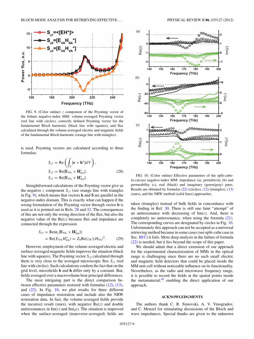
The most intriguing part is the direct comparison be-tween effective parameters restored with formulas (12), (13),and (22). In Fig. 10, we plot results for three differentcases of impedance restoration and include also the NRWrestoration data. In fact, the volume-averaged fields providethe incorrect result (stars), with negative Re(z) and doubleantiresonances in Im(ε) and Im(μ). The situation is improvedwhen the surface-averaged (transverse-averaged) fields are
(a)
(b)
(c)
FIG. 10. (Color online) Effective parameters of the split-cube-in-carcass negative-index MM: impedance (a), permittivity (b) andpermeability (c), real (black) and imaginary (green/gray) parts.Results are obtained by formulas (22) (circles), (12) (triangles), (13)(stars), and the NRW method (solid lines) approaches.
taken (triangles) instead of bulk fields in concordance withthe finding in Ref. 30. There is still one faint “attempt” ofan antiresonance with decreasing of Im(ε). And, there iscompletely no antiresonance, when using the formula (21).The corresponding curves are designated by circles in Fig. 10.Unfortunately this approach can not be accepted as a universalretrieving method because in some cases (see split-cube case inSec. III C) it fails. More deep analysis in the failure of formula(22) is needed, but it lies beyond the scope of this paper.
We should admit that a direct extension of our approachfor the experimental characterization of MMs in the opticalrange is challenging since there are no such small electricand magnetic field detectors that could be placed inside theMM unit cell without noticeable influence on its functionality.Nevertheless, as the radio and microwave frequency range,it is possible to record the fields at the spatial points insidethe metamaterial,40 enabling the direct application of ourapproach.
ACKNOWLEDGMENTS
The authors thank C. R. Simovski, A. V. Vinogradov,and C. Menzel for stimulating discussions of the Bloch andwave impedances. Special thanks are given to the unknown
035127-9

ANDREI ANDRYIEUSKI et al. PHYSICAL REVIEW B 86, 035127 (2012)
reviewer and M. Silveirinha for drawing our attention to thenature of computed fields and useful advice on the magneticfield correction. A. A. and A. V. L. acknowledge a financialsupport from the Danish Research Council for Technology and
Production Sciences via the NIMbus and GraTer (11-116991)projects. A.A.S. and Y.S.K acknowledge a support from theMinistry of Education and Science of Russian Federation(Russia) and Australian Research Council (Australia).
*[email protected] Handbook, edited by F. Capolino (CRC Press, BocaRaton, 2009).
2C. Simovski, Opt. Spectrosc. 107, 726 (2009).3C. Menzel, C. Rockstuhl, T. Paul, F. Lederer, and T. Pertsch, Phys.Rev. B 77, 195328 (2008).
4C. R. Simovski, Metamaterials 1, 62 (2007).5J. B. Pendry, Phys. Rev. Lett. 85, 3966 (2000).6D. R. Smith, S. Schultz, P. Markos, and C. M. Soukoulis, Phys. Rev.B 65, 195104 (2002).
7T. Koschny, P. Markos, D. R. Smith, and C. M. Soukoulis, Phys.Rev. E 68, 065602 (2003).
8R. A. Depine and A. Lakhtakia, Phys. Rev. E 70, 048601 (2004).9A. L. Efros, Phys. Rev. E 70, 048602 (2004).
10T. Koschny, P. Markos, D. R. Smith, and C. M. Soukoulis, Phys.Rev. E 70, 048603 (2004).
11C. R. Simovski and S. A. Tretyakov, Phys. Rev. B 75, 195111(2007).
12J. Zhou, T. Koschny, M. Kafesaki, and C. M. Soukoulis, Phys. Rev.B 80, 035109 (2009).
13A. Andryieuski, C. Menzel, C. Rockstuhl, R. Malureanu, and A. V.Lavrinenko, J. Opt. A: Pure Appl. Opt. 11, 114010 (2009).
14X. Chen, T. M. Grzegorczyk, B. I. Wu, J. Pacheco, and J. A. Kong,Phys. Rev. E 70, 016608 (2004).
15J. J. H. Cook, K. L. Tsakmakidis, and O. Hess, J. Opt. A: Pure Appl.Opt. 11, 114026 (2009).
16B. I. Popa and S. A. Cummer, Phys. Rev. B 72, 165102 (2005).17A. Andryieuski, R. Malureanu, and A. V. Lavrinenko, Phys. Rev. B
80, 193101 (2009).18J. M. Lerat, N. Mallejac, and O. Acher, J. Appl. Phys. 100, 084908
(2006).19D. R. Smith and J. B. Pendry, J. Opt. Soc. Am. B 23, 391 (2006).20O. Acher, J. M. Lerat, and N. Mallejac, Opt. Express 15, 1096
(2007).21A. Pors, I. Tsukerman, and S. Bozhevolnyi, Phys. Rev. E 84, 016609
(2011).22I. Tsukerman, J. Opt. Soc. Am. B 28, 577 (2011).23R. L. Chern and Y. T. Chen, Phys. Rev. B 80, 075118 (2009).24D. K. Morits and C. R. Simovski, Phys. Rev. B 81, 205112
(2010).25J. Petschulat, C. Menzel, A. Chipouline, C. Rockstuhl,
A. Tunnermann, F. Lederer, and T. Pertsch, Phys. Rev. A 78, 043811(2008).
26S. V. Zhukovsky, C. Kremers, and D. N. Chigrin, Opt. Lett. 36,2278 (2011).
27J. Yang, C. Sauvan, T. Paul, C. Rockstuhl, F. Lederer, and P. Lalanne,Appl. Phys. Lett. 97, 061102 (2010).
28J. T. Costa, M. G. Silveirinha, and A. Alu, Phys. Rev. B 83, 165120(2011).
29M. G. Silveirinha, Phys. Rev. B 83, 165104 (2011).30M. G. Silveirinha and C. A. Fernandes, Phys. Rev. E 75, 036613
(2007).
31M. G. Silveirinha, Phys. Rev. B 75, 115104 (2007).32M. G. Silveirinha, Phys. Rev. B 80, 235120 (2009).33J. T. Costa, M. G. Silveirinha, and S. I. Maslovski, Phys. Rev. B 80,
235124 (2009).34A. V. Chebykin, A. A. Orlov, A. V. Vozianova, S. I. Maslovski,
Yu. S. Kivshar, and P. A. Belov, Phys. Rev. B 84, 115438 (2011).35C. Fietz and G. Shvets, Phys. B: Condensed Matter 405, 2930
(2010).36S. Sun, S. T. Chui, and L. Zhou, Phys. Rev. E 79, 066604 (2009).37C. R. Simovski, J. Opt. 13, 013001 (2011).38S. Ha, A. A. Sukhorukov, K. B. Dossou, L. C. Botten, C. M. de
Sterke, and Yu. S. Kivshar, Opt. Lett. 34, 3776 (2009).39S. Ha, A. A. Sukhorukov, A. V. Lavrinenko, I. V. Shadrivov, D. A.
Powell, and Y. S. Kivshar, Appl. Phys. Lett. 98, 061909 (2011).40A. A. Sukhorukov, S. Ha, I. V. Shadrivov, D. A. Powell, and Yu. S.
Kivshar, Opt. Express 17, 3716 (2009).41CST Computer Simulation Technology AG [http://cst.com/].42P. Yeh, Optical Waves in Layered Media (Wiley, New York, 1988).43J. D. Joannopoulos, R. D. Meade, and J. N. Winn, Photonic
Crystals: Molding the Flow of Light (Princeton University Press,Princeton, 1995).
44P. St. J. Russell, T. A. Birks, and F. D. Lloyd Lucas, in ConfinedElectrons and Photons, edited by E. Burstein and C. Weisbuch(Plenum, New York, 1995), pp. 585–633.
45N. A. Mortensen, M. Yan, O. Sigmund, and O. Breinbjerg, J. Eur.Opt. Soc. Rapid Publ. 5, 10010 (2010).
46C. Rockstuhl, T. Paul, F. Lederer, T. Pertsch, T. Zentgraf, T. P.Meyrath, and H. Giessen, Phys. Rev. B 77, 035126 (2008).
47C. Menzel, C. Rockstuhl, R. Iliew, F. Lederer, A. Andryieuski,R. Malureanu, and A. V. Lavrinenko, Phys. Rev. B 81, 195123(2010).
48A. Andryieuski, C. Menzel, C. Rockstuhl, R. Malureanu, F. Lederer,and A. Lavrinenko, Phys. Rev. B 82, 235107 (2010).
49G. Dolling, C. Enkrich, M. Wegener, C. M. Soukoulis, andS. Linden, Opt. Lett. 31, 1800 (2006).
50A. Andryieuski, R. Malureanu, and A. Lavrinenko, J. Eur. Opt. Soc.Rapid Publ. 4, 09003 (2009).
51R. S. Penciu, K. Aydin, M. Kafesaki, Th. Koschny, E. Ozbay,E. N. Economou, and C. M. Soukoulis, Opt. Express 16, 18131(2008).
52W. Rotman, IRE Trans. Antennas Propag. 10, 82 (1962).53P. Belov, S. Tretyakov, and A. Viitanen, J. Electromagnet. Wave
16, 1153 (2002).54P. A. Belov, E. A. Yankovskaya, I. V. Melchakova, and C. R.
Simovski, Opt. Spectrosc. 109, 85 (2010).55Handbook of Optical Constants of Solids, edited by E. D. Palik
(Elsevier, Amsterdam, 1998).56The authors are aware that the permittivity of silver is not
described correctly by the Drude formula in the optical range andexperimentally measured data (Ref. 55) should be used instead.However, we can adopt the simplified material dispersion for thesake of testing the retrieval approach.
035127-10