
Blender Box 4 PDF - Blender Products | Engineered Air ... · Below is a chart that defines the...
4
BLENDER BOX High Performance Mixing Systems for New Applications © 2001 Blender Products, Inc. BB 11/01 Engineered Air Mixing Systems and Equipment 5010 Cook Street • Denver, Colorado 80216 Phone: 303.295.6111 • Fax: 303.296.1520 Toll-free: 800-523-5705 E-mail: [email protected] Internet: www.airblender.com BENEFITS: • Provides highest levels of mixing • Uses minimal energy • Requires minimal space • Packaged to take the guess work out of designing an efficient mixing system ®
Transcript of Blender Box 4 PDF - Blender Products | Engineered Air ... · Below is a chart that defines the...

BLENDER BOXHigh Performance Mixing Systems for New Applications
© 2001 Blender Products, Inc.BB 11/01
Engineered Air Mixing Systems and Equipment
5010 Cook Street • Denver, Colorado 80216Phone: 303.295.6111 • Fax: 303.296.1520Toll-free: 800-523-5705E-mail: [email protected]: www.airblender.com
BENEFITS:• Provides highest levels
of mixing • Uses minimal energy• Requires minimal space• Packaged to take the
guess work out of designing an efficient mixing system
®

Blender Box Overall Dimensions (Inches) Inlet Dimensions (Inches) Length (Inches)Model W1 H1 L A B E FBB4 34.0 22.75 23.75 30.0 7.75 11.75 12BB6 38.0 31.25 30.00 34.0 12.00 16.00 14BB8 50.0 31.25 32.00 46.0 12.00 16.00 16BB10 63.0 31.25 32.00 59.0 12.00 16.00 16BB12 63.0 31.25 32.00 59.0 12.00 16.00 16BB15 63.0 39.75 42.25 59.0 16.25 20.25 22BB18 75.0 39.75 42.25 71.0 16.25 20.25 22BB21 86.5 39.74 42.28 82.5 16.25 20.25 22BB24 98.5 39.75 42.25 94.5 16.25 20.25 22BB28 86.5 48.25 48.50 82.5 20.50 24.50 24BB32 98.5 48.25 48.50 94.5 20.50 24.50 24BB36 110.0 48.25 48.50 106.0 20.50 24.50 24BB40 115.5 18.25 48.50 111.5 20.50 24.50 24BB50 115.5 56.75 56.75 111.5 24.75 28.75 28BB60 115.5 65.25 65.00 111.5 29.00 33.00 32BB68 115.5 73.75 74.25 111.5 33.25 37.25 37BB83 144.0 82.25 83.50 140.0 37.50 41.50 42
The Series IV Air Blender® mixer provides the greatest amount ofmixing at the most predictable levels of any static mixing device onthe market. It is engineered to eliminate air stratification and therebyprevent freeze-stat trips and frozen coils, reduces sensor errors,and improves outside air dilution to help meet IAQ requirements.
However, one of the most common problems that designers,owners, and installers encounter when trying to apply a mixingdevice is the additional space that these devices require to operateefficiently. In response to this problem, Blender Products, Inc. hasdeveloped the Blender Box mixing system.The Blender Box mixing
unit is a complete mixing system that includes Air Blender mixers,Blender Section® unit, and dampers, that is designed and manufac-tured to fit standard and custom air handling units.The angleddamper arrangement combined with the engineered mixing section provides the greatest level of mixing in the shortest distance of any product on the market.
By specifying the Blender Box mixing system, designers, owners,and installers alike can be assured that the space, energy, and mixingeffectiveness of a system will be predictable and reliable.
(Side View Shown)
Dimensional Information
Optional Inlet Arrangements
Side View Top View

Below is a chart that defines the level of mixing provided by the Blender Box mixing unit at varying outside air percentages. MixingEffectiveness is the efficiency in which the entering temperature differential is reduced.Therefore, a mixing effectiveness of 0.00 meansthe entering temperature differential is unchanged (e.g. no mixing); whereas, a mixing effectiveness of 1.00 means that the entering temperature differential has been reduced to zero at the mixing box discharge (e.g. perfect mixing).
Mixing Effectiveness Chart
Selection and Specification Procedure
Correct Incorrect
Selecting and specifying the correct Blender Box mixing system for an air-handling unit consists of four steps.This procedure results in anefficient mixing system for each air-handling unit with predictable performance.
Step 1. Determine how the outdoor and return air streams will enter the mixing box.
The arrangement of the return and outdoor airstreams determines if multiple mixers can beused. In order to function properly, the sameamount of return and outdoor air must passthrough each mixer.This condition is usuallysatisfied whenever the inlets extend the fullwidth of the mixing box and does not approachthe air-handling unit from the side.
If the inlet condition willallow multiple mixers to be used, continue the selection procedureusing this selection guide. If this condition is not satisfied, consultyour local rep or the factory for the properselection of the Side Inlet Blender Box unit.
Multiple Mixer Application Single Mixer Application
Engineered Air Mixing Systems and Equipment
5010 Cook Street • Denver, Colorado 80216Phone: 303.295.6111 • Fax: 303.296.1520
Toll-free: 800-523-5705E-mail: [email protected]: www.airblender.com
Furnish Blender Box® mixing box generally consisting of dampers,Air Blender® static mixers, and mixing section fitted together in onerigid unit, as shown on drawings.
Unit shall be constructed of a minimum of 18 gauge steel outer wall,reinforced with 12 and 14 gauge steel welded framework and finishedwith corrosion resistant paint or zinc coating. Inlets shall be configured insuch a way that return and outside air may enter in any of four arrange-ments and arrangement shall be field adjustable by removing andre-installing inlet panels. Mixing section shall have sufficient distancedownstream to provide adequate mixing to meet mixing performance.
Dampers shall be of parallel blade low leakage, double air foil,proportioning type.These dampers shall have blades of roll formedgalvanized double wall equivalent to 16 gauge steel (stainless steeloptional) with neoprene seals on blade edges; and stainless steeledge seals.The damper shall have no blade wider than 6”. Damperblades shall be locked to steel rods rotating on rust proof bushings.Leakage to be less than 10 CFM per square foot at 4” S.P. Dampersection shall be fabricated from 18 gauge galvanized steel outerwall and 20 gauge galvanized steel inner liner to form a two inchthick insulated double wall. Damper section shall have viewport inside panels. Side panels shall be removable for damper access orservice. Damper actuators shall be furnished by others.
The Blender Box mixing box shall incorporate a Series IV AirBlender mixing device The air mixer or mixers shall be constructed ofa minimum .080” thick aluminum. Mixer shall be welded constructionwith a mechanically fastened center.The mixing device shall imparta counter rotational mixing of entering air streams. Each mixer modelshall be geometrically scaled to ensure proper performance acrossthe full range of sizes. Mixers that do not use counter rotationalmixing or are not geometrically scaled are not acceptable.
The unit shall have provisions for floor or ceiling mounting. EachBlender Box shall be equipped with duct connection flanges, sizedto match the inlet side of the Air Handling Unit, with no additionalor field transitions necessary.
The performance of the mixing equipment shall be stated in termsof Range Mixing Effectiveness. Mixing Effectiveness calculated usingthe standard deviation is not acceptable. Mixing equipment shallbe geometrically similar for all sizes.The pressure drop of mixersshall include mixer area ratio so that the “orifice effect” is included.If not geometrically similar, then each different size must be testedfor mixing performance and pressure drop. Detailed documentationof performance testing shall be made available upon request.
Units shall be manufactured by Blender Products, Inc., Denver,CO, or equal approved prior to bidding.
Step 4. Specify the Blender Box mixing sytem.
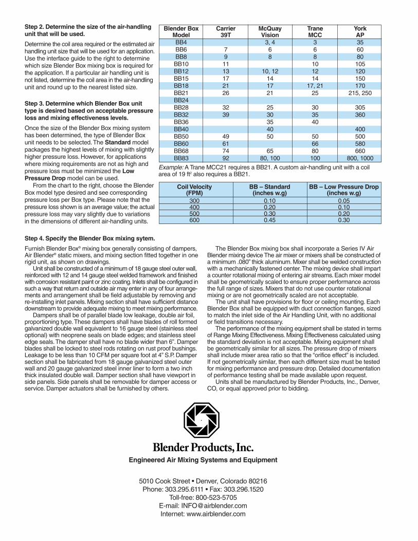
Example: A Trane MCC21 requires a BB21. A custom air-handling unit with a coilarea of 19 ft2 also requires a BB21.
Step 2. Determine the size of the air-handlingunit that will be used.
Determine the coil area required or the estimated airhandling unit size that will be used for an application.Use the interface guide to the right to determinewhich size Blender Box mixing box is required forthe application. If a particular air handling unit isnot listed, determine the coil area in the air-handlingunit and round up to the nearest listed size.
Step 3. Determine which Blender Box unittype is desired based on acceptable pressureloss and mixing effectiveness levels.
Once the size of the Blender Box mixing systemhas been determined, the type of Blender Boxunit needs to be selected.The Standard modelpackages the highest levels of mixing with slightlyhigher pressure loss. However, for applicationswhere mixing requirements are not as high andpressure loss must be minimized the LowPressure Drop model can be used.
From the chart to the right, choose the BlenderBox model type desired and see correspondingpressure loss per Box type. Please note that thepressure loss shown is an average value; the actualpressure loss may vary slightly due to variationsin the dimensions of different air-handling units.
Coil Velocity BB – Standard BB – Low Pressure Drop(FPM) (inches w.g) (inches w.g)300 0.10 0.05400 0.20 0.10500 0.30 0.20600 0.45 0.30
Blender Box Carrier McQuay Trane York Model 39T Vision MCC APBB4 3, 4 3 35BB6 7 6 6 60BB8 9 8 8 80BB10 11 10 105BB12 13 10, 12 12 120BB15 17 14 14 150BB18 21 17 17, 21 170BB21 26 21 25 215, 250BB24BB28 32 25 30 305BB32 39 30 35 360BB36 35 40BB40 40 400BB50 49 50 50 500BB60 61 66 580BB68 74 65 80 660BB83 92 80, 100 100 800, 1000