BLDC Shield TLE9563-3QX - Infineon Technologies
22
User manual Please read the Important Notice and Warnings at the end of this document V 1.0 www.infineon.com page 1 of 22 2020-06-23 AppNote Number BLDC Shield TLE9563-3QX About this document Scope and purpose This user manual describes the BLDC shield with the TLE9563-3QX. This document provides detailed information on the board’s content, layout and use. It should be used in conjunction with the TLE9563-3QX datasheet, which contains full technical details on the device specification and operation. Intended audience This document is intended for users who develop applications with the TLE956x family. Table of contents About this document ....................................................................................................................... 1 Table of contents ............................................................................................................................ 1 1 Introduction .......................................................................................................................... 1 2 Hardware description ............................................................................................................. 3 2.1 Hardware ................................................................................................................................................. 3 2.2 Schematic ................................................................................................................................................ 8 2.3 Layout .................................................................................................................................................... 12 2.4 Bill of Material ........................................................................................................................................ 14 3 Start and uIO stick programmation ......................................................................................... 15 3.1 Download the Graphic User Interface for the uIO stick ....................................................................... 15 3.2 Configuration Wizard for TLE9563-3QX ................................................................................................ 15 4 Config Wizard - Control tabs ................................................................................................... 16 4.1 SBC ......................................................................................................................................................... 16 4.2 Bridge Driver .......................................................................................................................................... 19 Revision history............................................................................................................................. 21 1 Introduction The TLE9653-3QX evaluation board is intended to provide a simple and easy-to-use tool for getting familiar with the device features and for first application tests. The evaluation board can be used wither with a uIO-stick, or with an Arduino Uno. The uIO-stick is the interface between the PC and the application board such as the TLE9563-3QX. The TLE9563-3QX SPI communication is emulated by the uIO-stick, which is controlled by the PC software. The board of the TLE9563-3QX has a connector for the uIO-stick, connectors for the power supply, three connector for the motor output. And an active reverse battery protection with IPZ40N4S5L-2R8.
Transcript of BLDC Shield TLE9563-3QX - Infineon Technologies

User manual Please read the Important Notice and Warnings at the end of this document V 1.0
www.infineon.com page 1 of 22 2020-06-23
AppNote Number
BLDC Shield TLE9563-3QX
About this document
Scope and purpose
This user manual describes the BLDC shield with the TLE9563-3QX. This document provides detailed
information on the board’s content, layout and use. It should be used in conjunction with the TLE9563-3QX datasheet, which contains full technical details on the device specification and operation.
Intended audience
This document is intended for users who develop applications with the TLE956x family.
Table of contents
About this document ....................................................................................................................... 1
Table of contents ............................................................................................................................ 1
1 Introduction .......................................................................................................................... 1
2 Hardware description ............................................................................................................. 3
2.1 Hardware ................................................................................................................................................. 3 2.2 Schematic ................................................................................................................................................ 8
2.3 Layout .................................................................................................................................................... 12
2.4 Bill of Material ........................................................................................................................................ 14
3 Start and uIO stick programmation ......................................................................................... 15 3.1 Download the Graphic User Interface for the uIO stick ....................................................................... 15
3.2 Configuration Wizard for TLE9563-3QX ................................................................................................ 15
4 Config Wizard - Control tabs ................................................................................................... 16 4.1 SBC ......................................................................................................................................................... 16
4.2 Bridge Driver .......................................................................................................................................... 19
Revision history............................................................................................................................. 21
1 Introduction
The TLE9653-3QX evaluation board is intended to provide a simple and easy-to-use tool for getting familiar
with the device features and for first application tests.
The evaluation board can be used wither with a uIO-stick, or with an Arduino Uno.
The uIO-stick is the interface between the PC and the application board such as the TLE9563-3QX.
The TLE9563-3QX SPI communication is emulated by the uIO-stick, which is controlled by the PC software.
The board of the TLE9563-3QX has a connector for the uIO-stick, connectors for the power supply, three
connector for the motor output. And an active reverse battery protection with IPZ40N4S5L-2R8.

User manual 2 of 22 V 1.0
2020-06-23
BLDC Shield TLE9563-3QX
Figure 1 TLE9563-3QX Eval. Board concept
1) The uIO stick must be ordered separately – SP001215532
Details about the uIO stick can be found hear: www.hitex.com/uIO
User manual 3 of 22 V 1.0
2020-06-23
BLDC Shield TLE9563-3QX
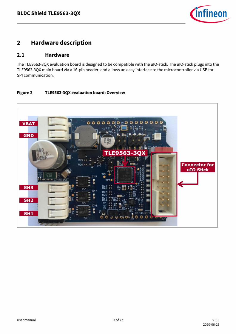
2 Hardware description
2.1 Hardware
The TLE9563-3QX evaluation board is designed to be compatible with the uIO-stick. The uIO-stick plugs into the TLE9563-3QX main board via a 16-pin header, and allows an easy interface to the microcontroller via USB for
SPI communication.
Figure 2 TLE9563-3QX evaluation board: Overview

User manual 4 of 22 V 1.0
2020-06-23
BLDC Shield TLE9563-3QX
Figure 3 TLE9563-3QX evaluation board
Figure 4 TLE9563-3QX evaluation board

User manual 5 of 22 V 1.0
2020-06-23
BLDC Shield TLE9563-3QX
Figure 5 TLE9563-3QX evaluation board: Jumper settings 1/3
Test-Mode jumper: Software Development Mode is a dedicated SBC configuration especially useful for
software development. When the jumper is set, the watchdog is disabled.
Attention: The uIO stick does not refresh the watchdog. Therefore, for a correct operation with the uIO stick, the Jumper for Test Mode must be placed in order to enable the software development
mode and to deactivate the watchdog

User manual 6 of 22 V 1.0
2020-06-23
BLDC Shield TLE9563-3QX
Figure 6 TLE9563-3QX evaluation board: Jumper settings 2/3
Figure 7 TLE9563-3QX evaluation board
User manual 7 of 22 V 1.0
2020-06-23
BLDC Shield TLE9563-3QX
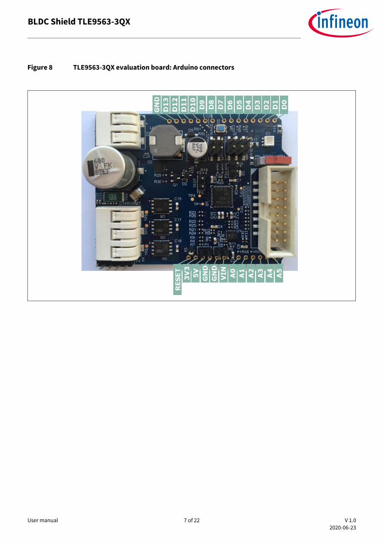
Figure 8 TLE9563-3QX evaluation board: Arduino connectors
User manual 8 of 22 V 1.0
2020-06-23
BLDC Shield TLE9563-3QX
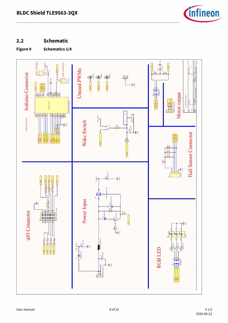
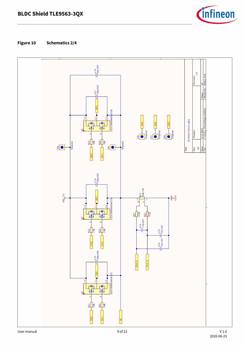
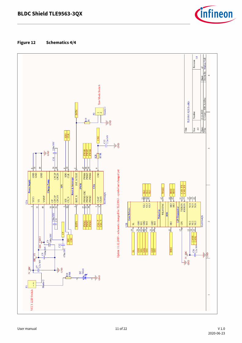
2.2 Schematic
Figure 9 Schematics 1/4
User manual 9 of 22 V 1.0
2020-06-23
BLDC Shield TLE9563-3QX
Figure 10 Schematics 2/4

User manual 10 of 22 V 1.0
2020-06-23
BLDC Shield TLE9563-3QX
Figure 11 Schematics 3/4
User manual 11 of 22 V 1.0
2020-06-23
BLDC Shield TLE9563-3QX
Figure 12 Schematics 4/4
User manual 12 of 22 V 1.0
2020-06-23
BLDC Shield TLE9563-3QX
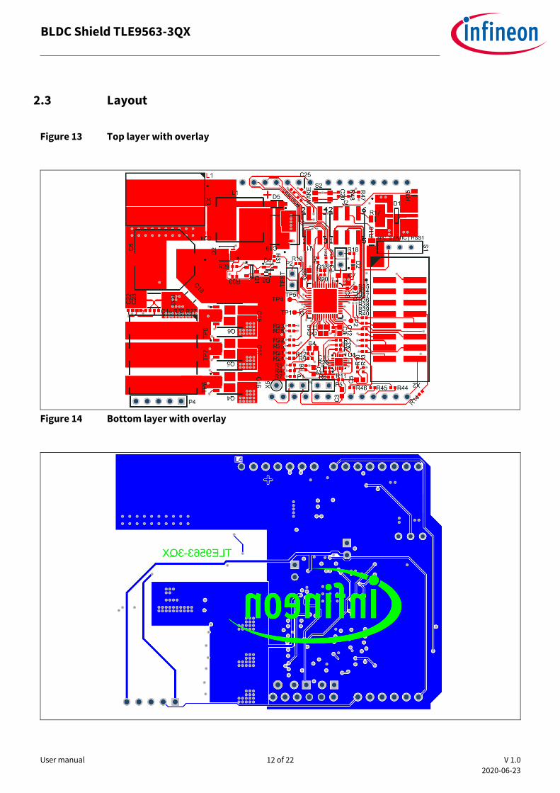
2.3 Layout
Figure 13 Top layer with overlay
Figure 14 Bottom layer with overlay

User manual 13 of 22 V 1.0
2020-06-23
BLDC Shield TLE9563-3QX
Figure 15 Inner layer - GND
<

User manual 14 of 22 V 1.0
2020-06-23
BLDC Shield TLE9563-3QX
2.4 Bill of Material
Figure 16 Bill of Material
User manual 15 of 22 V 1.0
2020-06-23
BLDC Shield TLE9563-3QX
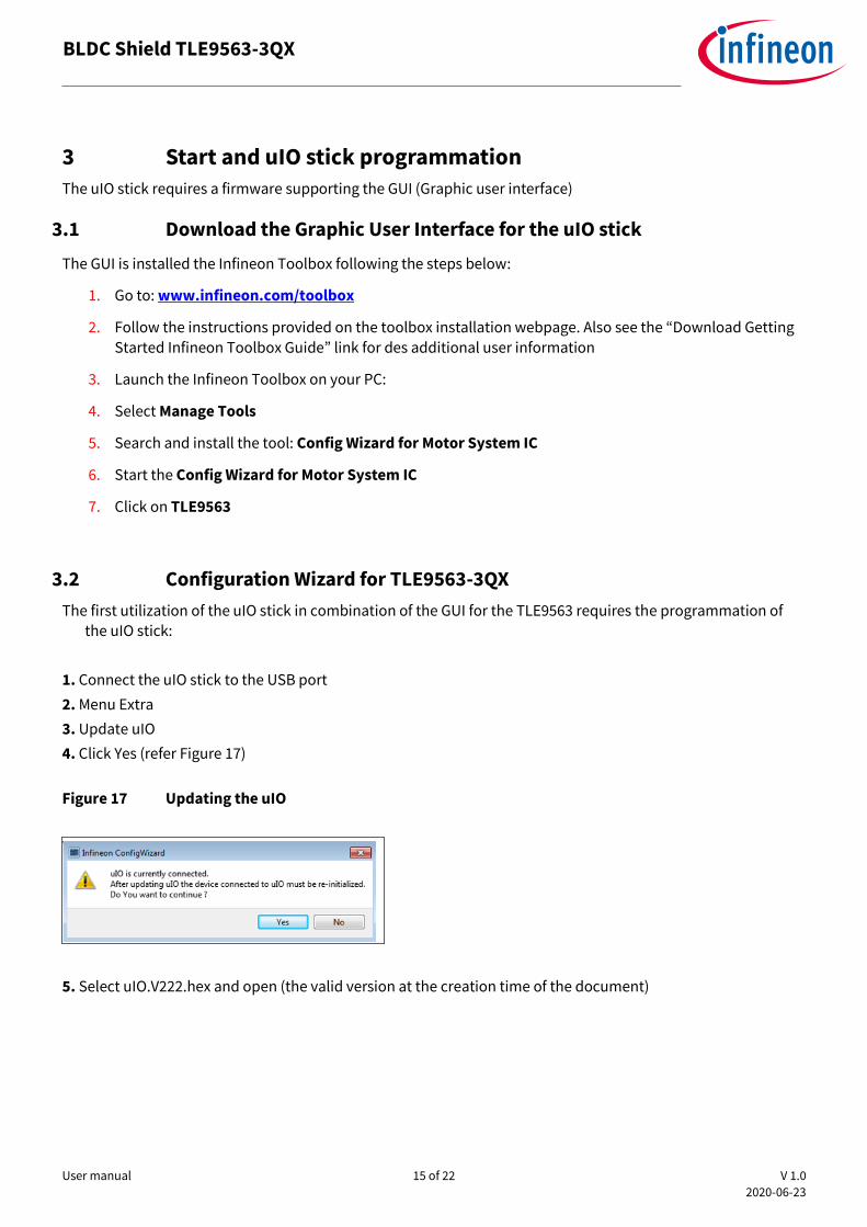
3 Start and uIO stick programmation
The uIO stick requires a firmware supporting the GUI (Graphic user interface)
3.1 Download the Graphic User Interface for the uIO stick
The GUI is installed the Infineon Toolbox following the steps below:
1. Go to: www.infineon.com/toolbox
2. Follow the instructions provided on the toolbox installation webpage. Also see the “Download Getting
Started Infineon Toolbox Guide” link for des additional user information
3. Launch the Infineon Toolbox on your PC:
4. Select Manage Tools
5. Search and install the tool: Config Wizard for Motor System IC
6. Start the Config Wizard for Motor System IC
7. Click on TLE9563
3.2 Configuration Wizard for TLE9563-3QX
The first utilization of the uIO stick in combination of the GUI for the TLE9563 requires the programmation of the uIO stick:
1. Connect the uIO stick to the USB port
2. Menu Extra
3. Update uIO
4. Click Yes (refer Figure 17)
Figure 17 Updating the uIO
5. Select uIO.V222.hex and open (the valid version at the creation time of the document)

User manual 16 of 22 V 1.0
2020-06-23
BLDC Shield TLE9563-3QX
4 Config Wizard - Control tabs
Figure 18 The two main tabs SBC, Bridge Driver
4.1 SBC
Figure 19 Connection Status/ Signaling Pin Status
Figure 20 Overview of the SBC tab
User manual 17 of 22 V 1.0
2020-06-23
BLDC Shield TLE9563-3QX
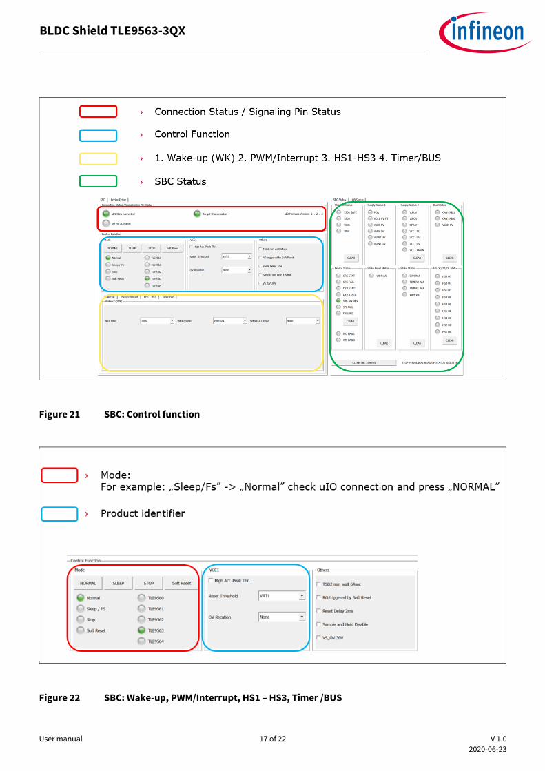
Figure 21 SBC: Control function
Figure 22 SBC: Wake-up, PWM/Interrupt, HS1 – HS3, Timer /BUS
User manual 18 of 22 V 1.0
2020-06-23
BLDC Shield TLE9563-3QX
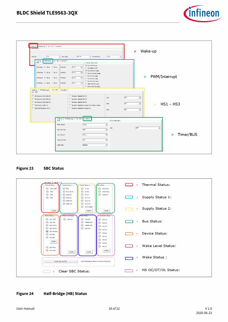
Figure 23 SBC Status
Figure 24 Half-Bridge (HB) Status

User manual 19 of 22 V 1.0
2020-06-23
BLDC Shield TLE9563-3QX
4.2 Bridge Driver
Figure 25 Bridge Driver: 1st Tab – General, CSA, VDS Monitoring (Mon)
Figure 26 Bridge Driver: 2nd Tab – Blank/ CCP time, HBMODE, Brake, TDON/ TDOFF Timing

User manual 20 of 22 V 1.0
2020-06-23
BLDC Shield TLE9563-3QX
Figure 27 Bridge Driver: 3rd Tab – MOSFET Drive Currents

User manual 21 of 22 V 1.0
2020-06-23
BLDC Shield TLE9563-3QX
Revision history
Document
version
Date of release Description of changes
V 1.0 2020-06-23 Initial version

Trademarks All referenced product or service names and trademarks are the property of their respective owners.
Edition 2020-06-23
AppNote Number
Published by
Infineon Technologies AG
81726 Munich, Germany
© 2020 Infineon Technologies AG.
All Rights Reserved.
Do you have a question about this
document?
Email: [email protected]
Document reference
IMPORTANT NOTICE The information contained in this application note is given as a hint for the implementation of the product only and shall in no event be regarded as a description or warranty of a certain functionality, condition or quality of the product. Before implementation of the product, the recipient of this application note must verify any function and other technical information given herein in the real application. Infineon Technologies hereby disclaims any and all warranties and liabilities of any kind (including without limitation warranties of non-infringement of intellectual property rights of any third party) with respect to any and all information given in this application note. The data contained in this document is exclusively intended for technically trained staff. It is the responsibility of customer’s technical departments to evaluate the suitability of the product for the intended application and the completeness of the product information given in this document with respect to such application.
For further information on the product, technology, delivery terms and conditions and prices please contact your nearest Infineon Technologies office (www.infineon.com).
WARNINGS Due to technical requirements products may contain dangerous substances. For information on the types in question please contact your nearest Infineon Technologies office. Except as otherwise explicitly approved by Infineon Technologies in a written document signed by authorized representatives of Infineon Technologies, Infineon Technologies’ products may not be used in any applications where a failure of the product or any consequences of the use thereof can reasonably be expected to result in personal injury.