
Blast loading of bumper shielded hybrid two-core Miura-ori ... · analyzed with the commercial...
13
Contents lists available at ScienceDirect Thin-Walled Structures journal homepage: www.elsevier.com/locate/tws Full length article Blast loading of bumper shielded hybrid two-core Miura-ori/honeycomb core sandwich plates Anup Pydah, R.C. Batra ⁎ Department of Biomedical Engineering and Mechanics, M/C 0219, Virginia Polytechnic Institute and State University, Blacksburg, VA 24061, USA ARTICLE INFO Keywords: Miura-ori core Honeycomb core Blast mitigation Whipple shield Elastic-plastic material Transient deformations Bumper ABSTRACT We analyze transient elasto-plastic deformations of two-core sandwich plates with and without a bumper and subjected to blast loads with the objective of ascertaining the energy dissipated due to plastic deformations. The facesheets and the core are assumed to be made of a high strength steel modeled as an isotropic material that obeys the von Mises yield criterion with linear strain hardening. It is first shown that considering a material failure criterion and deleting failed elements does not noticeably affect the energy dissipated in a sandwich plate. Subsequent analyses of two-core structures with and without a blast shield ignore the material failure and assume facesheets to be perfectly bonded to the core. The nonlinear transient problems have been numerically analyzed with the commercial finite element software, ABAQUS/ Explicit. Four different two-core sandwich plates obtained by varying locations of the Miura-ori and honeycomb cores are considered. Results without a shield indicate that using a Miura-ori core beneath the topmost facesheet dissipates more energy for moderate blast loads, while a combination of a honeycomb and a Miura-ori core has the least facesheet deflections. The effects of using a blast shield or a bumper, at a fixed standoff distance from a honeycomb-Miura sandwich panel, is studied by ensuring that the shield and the sandwich structure combination has the same areal density as the sandwich panel without the shield. It is found that for a given blast load, using the shield significantly reduces the energy dissipated in the sandwich panel, the bottom facesheet maximum centroidal deflection and the maximum plastic strain in the cores when compared with equal-weight panels without a shield. For the same energy dissipation, the structure with a blast shield has approximately 42% less weight than that without the shield. 1. Introduction Sandwich panels are widely used as primary load bearing members in high-performance aerospace, naval and automobile industries be- cause of their multi-functionality, high stiffness-to-weight ratios and their capability to be tailored to meet design requirements. Discrete or cellular sandwich cores, constructed as a corrugated sheet or square/ hexagonal cell honeycombs, dissipate a significant amount of incident energy through a combination of their plastic compression, and bending and transverse shear deformations of the core [1], making them ideally suited for blast-mitigating applications. The mechanical response of single cellular-core sandwich structures subjected to air or underwater blast loads has been investigated using both, homogenized [2–5] and discrete core models [6–16]. These stu- dies have established that sandwich structures have higher specific energy dissipation than solid plates of the same areal density, and have indicated the superiority of the honeycomb core architecture over other core geometries [17]. However, moisture accumulation in sealed honeycomb cells can severely compromise their mechanical perfor- mance. Novel core architectures [18–22], including origami-based de- signs, can help mitigate this problem and further improve the perfor- mance of sandwich structures. Investigations on quasi-static deformations of single Miura-ori sandwich cores [23,24] and on transient deformations of blast-loaded stacked Miura-ori core sandwich beams [25] have shown the effec- tiveness of the Miura-ori core architecture. Design studies on single- core Miura-ori and honeycomb core sandwich plates subjected to high- intensity dynamic loads [26] have found that the Miura-ori core con- sistently outperforms the honeycomb core of equal areal density in terms of the energy dissipated through plastic deformations, particu- larly for moderate blast intensities. Dual-core or multi-core sandwich panels consisting of two or more cores separated by metallic or composite facesheets have been shown to be superior to equal areal density single-core structures in terms of their impact resistance [27,28], energy absorption [29] and sound-absorbing capabilities [30]. Infinitesimal elastic deformations of multilayered https://doi.org/10.1016/j.tws.2018.03.020 Received 31 October 2017; Received in revised form 7 February 2018; Accepted 22 March 2018 ⁎ Corresponding author. E-mail addresses: [email protected] (A. Pydah), [email protected] (R.C. Batra). Thin-Walled Structures 129 (2018) 45–57 0263-8231/ © 2018 Elsevier Ltd. All rights reserved. T
Transcript of Blast loading of bumper shielded hybrid two-core Miura-ori ... · analyzed with the commercial...

Contents lists available at ScienceDirect
Thin-Walled Structures
journal homepage: www.elsevier.com/locate/tws
Full length article
Blast loading of bumper shielded hybrid two-core Miura-ori/honeycombcore sandwich plates
Anup Pydah, R.C. Batra⁎
Department of Biomedical Engineering and Mechanics, M/C 0219, Virginia Polytechnic Institute and State University, Blacksburg, VA 24061, USA
A R T I C L E I N F O
Keywords:Miura-ori coreHoneycomb coreBlast mitigationWhipple shieldElastic-plastic materialTransient deformationsBumper
A B S T R A C T
We analyze transient elasto-plastic deformations of two-core sandwich plates with and without a bumper andsubjected to blast loads with the objective of ascertaining the energy dissipated due to plastic deformations. Thefacesheets and the core are assumed to be made of a high strength steel modeled as an isotropic material thatobeys the von Mises yield criterion with linear strain hardening. It is first shown that considering a materialfailure criterion and deleting failed elements does not noticeably affect the energy dissipated in a sandwich plate.Subsequent analyses of two-core structures with and without a blast shield ignore the material failure andassume facesheets to be perfectly bonded to the core. The nonlinear transient problems have been numericallyanalyzed with the commercial finite element software, ABAQUS/ Explicit. Four different two-core sandwichplates obtained by varying locations of the Miura-ori and honeycomb cores are considered. Results without ashield indicate that using a Miura-ori core beneath the topmost facesheet dissipates more energy for moderateblast loads, while a combination of a honeycomb and a Miura-ori core has the least facesheet deflections. Theeffects of using a blast shield or a bumper, at a fixed standoff distance from a honeycomb-Miura sandwich panel,is studied by ensuring that the shield and the sandwich structure combination has the same areal density as thesandwich panel without the shield. It is found that for a given blast load, using the shield significantly reducesthe energy dissipated in the sandwich panel, the bottom facesheet maximum centroidal deflection and themaximum plastic strain in the cores when compared with equal-weight panels without a shield. For the sameenergy dissipation, the structure with a blast shield has approximately 42% less weight than that without theshield.
1. Introduction
Sandwich panels are widely used as primary load bearing membersin high-performance aerospace, naval and automobile industries be-cause of their multi-functionality, high stiffness-to-weight ratios andtheir capability to be tailored to meet design requirements. Discrete orcellular sandwich cores, constructed as a corrugated sheet or square/hexagonal cell honeycombs, dissipate a significant amount of incidentenergy through a combination of their plastic compression, andbending and transverse shear deformations of the core [1], makingthem ideally suited for blast-mitigating applications.
The mechanical response of single cellular-core sandwich structuressubjected to air or underwater blast loads has been investigated usingboth, homogenized [2–5] and discrete core models [6–16]. These stu-dies have established that sandwich structures have higher specificenergy dissipation than solid plates of the same areal density, and haveindicated the superiority of the honeycomb core architecture over othercore geometries [17]. However, moisture accumulation in sealed
honeycomb cells can severely compromise their mechanical perfor-mance. Novel core architectures [18–22], including origami-based de-signs, can help mitigate this problem and further improve the perfor-mance of sandwich structures.
Investigations on quasi-static deformations of single Miura-orisandwich cores [23,24] and on transient deformations of blast-loadedstacked Miura-ori core sandwich beams [25] have shown the effec-tiveness of the Miura-ori core architecture. Design studies on single-core Miura-ori and honeycomb core sandwich plates subjected to high-intensity dynamic loads [26] have found that the Miura-ori core con-sistently outperforms the honeycomb core of equal areal density interms of the energy dissipated through plastic deformations, particu-larly for moderate blast intensities.
Dual-core or multi-core sandwich panels consisting of two or morecores separated by metallic or composite facesheets have been shown tobe superior to equal areal density single-core structures in terms of theirimpact resistance [27,28], energy absorption [29] and sound-absorbingcapabilities [30]. Infinitesimal elastic deformations of multilayered
https://doi.org/10.1016/j.tws.2018.03.020Received 31 October 2017; Received in revised form 7 February 2018; Accepted 22 March 2018
⁎ Corresponding author.E-mail addresses: [email protected] (A. Pydah), [email protected] (R.C. Batra).
Thin-Walled Structures 129 (2018) 45–57
0263-8231/ © 2018 Elsevier Ltd. All rights reserved.
T

foldcore sandwich panels have been analytically studied [31], however,the mechanics of transient deformations of the elasto-plastic core underdynamic loads [25,26] is quite involved due to inertia effects. For singlecore elasto-plastic sandwich plates with the Miura-ori and the honey-comb cores [26] of equal areal density with material failure not con-sidered, we found that while the bottom facesheet of the Miura-ori coresandwich plate had lesser maximum deflection the honeycomb coreconsiderably reduced the top facesheet maximum deflection. Further-more, for moderate blast intensities, the Miura-ori cores dissipated agreater fraction of the incident energy through plastic deformationsthan the honeycomb cores.
In terms of structural reliability, an ideal sandwich panel shoulddissipate large quantities of energy without sacrificing its integrity. Thishas motivated us to study two-core sandwich plates with the Miura-oriand the honeycomb core located in either the top or the bottom layer,which gives four combinations - Miura-honeycomb, honeycomb-Miura,Miura-Miura and honeycomb-honeycomb, wherein the first term refersto the top core that first interacts with the blast load.
For space structures, a thin shield placed at a distance above theprimary structure, known as a Whipple bumper [32], efficiently reducesthe penetration due to hypervelocity meteoric impact and offers con-siderable weight savings [33–39]. For aircrafts, a Hardened Unit LoadDevice (HULD) [40] and an overhead bin blast composite shield [41]provide on-board countermeasures against small explosions. There is aclear need for research on shielding aircraft, automobile and navalstructures from high-intensity dynamic loads caused by explosive blastsor crashes.
Thus, objectives of this paper are to:
1. Examine effects of a Whipple shield, i.e., a thin metallic plate lo-cated above the primary structure and interacting first with the blastload.
2. Delineate effects of considering material failure and deleting failedelements from the analysis.
3. Investigate the blast performance of hybrid two-core sandwichstructures designed as a combination of Miura-ori and square hon-eycomb core layers perfectly bonded to facesheets.
The finite element (FE) software ABAQUS/ Explicit ver. 6.14 [42] isused to numerically solve the pertinent nonlinear initial-boundary-value elastic-plastic problems by using the FE mesh that gave convergedresults for a prototype one-core sandwich structure. It is found thatconsidering a damage model and deleting failed elements has a minimaleffect on the energy absorbed and the maximum deflection of thestructure. Material strain rate effects, thermal softening, debondingbetween the core and the facesheets and imperfections, if any, in thecores have not been considered.
Design studies conducted to investigate the influence of the unit cellparameters of the Miura-ori and the honeycomb pattern on the sand-wich panel deformations indicate that design trade-offs need to beconsidered. The Miura-ori core in the top layer dissipates more energythrough plastic deformations, and the honeycomb-Miura combinationminimizes the facesheet deflections. Using a panel with a Whippleshield reduces the back facesheet maximum deflection and decreasesthe maximum equivalent plastic strain in the cores when comparedwith an equal areal density panel without the shield. For the sameenergy dissipation under a given blast load, the structure with a blastshield has approximately 42% less weight than that without the shield.
The layout of the remainder of the paper is as follows. The geometryof the two-core Miura-ori and honeycomb sandwich plate, the con-stitutive relations for the material and the FE modeling in ABAQUS/Explicit are described in Section 2. Results for (i) a single-layer sand-wich plate under blast loads with and without considering materialfailure, and (ii) a single fold with and without accounting for pre-da-mage induced in its crease during the fabrication process are also dis-cussed in Section 2. The collapse kinematics and the response of the
four two-core sandwich plates under blast loads are described inSection 3. The influence of unit cell parameters on the energy dissipateddue to plastic deformations in the cores and on the facesheet deflectionsof the two-core sandwich plates are presented in Section 4. The influ-ence of a blast shield on deformations of a honeycomb-Miura sandwichplate is examined in Section 5. In Section 6 we comment upon experi-mental work needed to verify results of simulations. Conclusions of thework are summarized in Section 7.
2. Geometry and modeling of the hybrid two-core sandwich plate
The hybrid two-core sandwich plate consists of a top, a middle, anda bottom facesheet with two cores (of either a Miura-ori or a honey-comb-type architecture) between a pair of facesheets (see, for example,Fig. 1, for the “honeycomb-Miura” combination). The three facesheets,assumed here to be identical for simplicity, have dimensionsA× B×hf and the core thickness equals H. The edges of the facesheetsare rigidly clamped and a high-intensity dynamic load given by
= ⎧⎨⎩
<≥−p r t
t tp t t t
( , )0
( )ea
r ra
( / )0 2(1)
where
= ⎡⎣⎢
− − ⎤⎦⎥
− −p t P t tt
( ) 1 ea
d
t t t0
( )/a θ
(2)
is applied to the outer surface of the top facesheet. The blast pressure isadapted from the numerical studies of Dharmasena et al. [9], and ex-ponentially decreases with distance r from the facesheet centroid ac-cording to Eq. (1). The peak overpressure P0 occurs at =r 0 and time
=t ta and decreases exponentially with time >t ta (see Fig. 2). We set,=r 500 mm, =t 20 μsa , =t 180 μsd and =t 189.8 μsθ . Batra and Hassan
[43] considered p to be a polynomial of degree 4 in r and exponentiallydecaying in time with various parameters given by Cole's [44] empiricalformulae.
The Miura-ori core consists of xm and ym “unit cells” tessellatedalong and across the corrugation, respectively. A single unit cell isconstructed from four identical parallelograms which can be char-acterized by four parameters in its unfolded state: side lengths a and b,
Fig. 1. “Honeycomb-Miura” hybrid sandwich plate.
Fig. 2. Time and spatial (inset) variation of the high-intensity dynamic load(Eq. (2)).
A. Pydah, R.C. Batra Thin-Walled Structures 129 (2018) 45–57
46

acute angle α and the sheet thickness ts (Fig. 3). In a particular foldedconfiguration, the Miura-ori unit cell requires an additional parameter,the dihedral fold angle θ between the facets and the horizontal base, tocompletely characterize the core. Alternatively, a unit cell can also bedescribed by its outer dimensions, height H, width S2 , length, L2 , andamplitude V given by [45]
= =+
H a θ α S b θ αθ α
sin sin , cos tan1 cos tan2 2 (3)
= − =+
L a θ α V bθ α
1 sin sin , 11 cos tan
2 22 2 (4)
The relative mass density, ρc, of the Miura-ori core is given by
=ρ a b t αH S L
ρsinc
sm (5)
where ρm is the mass density of the core material.The square honeycomb core consists of a set of orthogonal webs
x y( , )m m of height H and thickness tw running in the −x and the −ydirections.
The relative mass density, ρc, of the honeycomb core is given by
=+
ρx y t
aρ
( )c
m m wm (6)
The dimensions of the Miura-ori unit cell are chosen as= =a b 11.18 mm, =α 66.42 deg, =t 0.218 mms , and =H 5 mm. This
results in a Miura-ori core with =x y{ , } {5, 5}m m and the dihedral angle=θ 29.21 deg. For the honeycomb core, a grid of 25 webs with
=x y{ , } {5, 5}m m is chosen with =t 0.5 mmw and =H 5 mm. In order tocompare the performance of the Miura-ori and the square honeycombcores of equal areal density, the facesheet dimensions were fixed at100×100×2mm and the core density at approximately ρ0.05 m.
2.1. Material parameters
The facesheets and the cores are made of the same homogeneous,isotropic, bilinear elastic-plastic material that obeys the von Mises yieldcriterion with isotropic hardening that is representative of a HighStrength Low Alloy steel HSLA-65. We set = −ρ 7800 kg mm
3, Young'smodulus =E 200 GPa, Poisson's ratio =ν 0.3, yield stress =σ 300y MPaand the hardening tangent modulus =E 2t GPa.
For studying material failure, we use the Johnson-Cook failure cri-terion [46] included in ABAQUS 6.14 [42]. Damage is assumed to in-itiate when
=Σ Δϵϵ
1D
pl
pl (7)
where Δϵpl is the increment in the equivalent plastic strain and thesummation is performed over all increments of loading. The equivalentplastic strain, ϵD
pl, is defined as
⎜ ⎟= + − ⎡⎣⎢
+ ⎛⎝
⎞⎠
⎤⎦⎥
+d d d η d d θϵ [ exp( )] 1 ln ϵϵ
[1 ]Dpl
1 2 3 4pl
05
(8)
which accounts for effect of the stress triaxiality, strain rate, and tem-perature. In Eq. (8), −d d1 5 are material parameters, = −η p q/ is thestress triaxiality coefficient, p the hydrostatic pressure (negative intension), q the von Mises equivalent stress, ϵpl the equivalent plasticstrain rate, ϵ0 the reference strain rate and θ is the non-dimensionaltemperature defined as
=⎧
⎨⎩
<− − ≤ ≤
>θ
θ θθ θ θ θ θ θ θ
θ θ
0( )/( )1
transition
transition melt transition transition melt
melt (9)
Here θ, θmelt and θtransition are, respectively, the current, the melting andthe transition temperatures. Upon the damage onset, Young's modulusis degraded by − D(1 ) with the damage variable D computed from
=D uu
˙ ˙
f
pl
pl(10)
where ufpl is the effective plastic displacement at the point of failure and
is introduced to reduce the mesh dependency of the computed results.The value of uf
pl can be directly specified by the user or given in terms of
the fracture energy dissipated per unit area, Gf , as =ufGσ
pl 2 f
ywhere σy is
the current yield stress. The element is deleted from the analysis do-main when =D 1 at one of its integration points. Setting =u 0f
pl impliesinstantaneous failure of the element when Eq. (7) holds.
We set =d 0.051 , =d 3.442 , =d 2.123 and = =d d 04 5 which is re-presentative of a 4340 Steel [46] with the assumption of neglectingstrain rate and temperature effects. Results are computed for a range ofvalues of uf
pl.The structure is assumed to be initially at rest and stress free.
2.2. FE meshes
The facesheets of the sandwich plate were discretized using eight-node C3D8R brick elements with reduced integration into × ×60 60 3uniform elements. The Miura-ori and the honeycomb cores were me-shed using four-node S4R shell elements with reduced integration. Each
Fig. 3. Geometric parameters of a Miura-ori unit cell.
A. Pydah, R.C. Batra Thin-Walled Structures 129 (2018) 45–57
47
parallelogram facet of the Miura-ori core was meshed with ×20 20uniform elements while each web of the honeycomb core was meshedwith 20 uniform elements along its depth and 60 uniform elementsalong its length. In Ref. [26] we showed that results for shock loadsusing these shell elements and the C3D8R elements for the core werevirtually identical to each other.
To simulate perfect bonding, the cores were attached to the face-sheets using the tie constraint. The general contact algorithm inABAQUS was used to ensure frictionless contact and non-inter-penetration between surfaces that may contact each other during thedeformation process.
2.3. Mesh convergence study
We computed the response of a single-core Miura-ori sandwich platewith =x y{ , } {5, 5}m m , =H 10 mm subjected to a blast load given by Eq.(1) with =P 1000 MPa applied to the outer surface of the top facesheet.We used mesh densities ranging from ×10 10(14, 400 total) to ×25 25(78, 400 total) elements in each core facet. For the facesheets, we used
× ×60 60 3 uniform elements. Key results presented in Table 1 at=t 3 ms indicate that the global response quantities like the maximum
equivalent plastic strain in the core, ϵp, and the energy dissipated due toplastic deformations, PD, in the core as well as local quantities like thecentroidal deflections of the facesheets, converged for the ×20 20 FEmesh in a core facet. For all numerical simulations in this paper, wehave used ×20 20 uniform elements in each Miura-ori core facet and
×20 60 uniform elements for each web of the honeycomb core forwhich results with different meshes were not computed.
2.4. Comparison of results with and without considering material failure
For =P 1000 and 300MPa in Eq. (1), and a range of values of ufpl, the
computed results at =t 3 ms are listed in Table 2. These reveal that for=P 1000 MPa, there is a minimal influence of the uf
pl value on the
energy dissipated due to plastic deformations in the structure and thefacesheet deflections. For =P 3000 MPa, the energy dissipated and thetop facesheet deflections are little changed when uf
pl is increased from 0
to 0.01 mm. For subsequent increase in the ufpl value to 10mm, the four
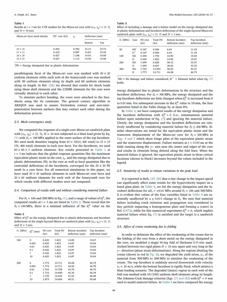
quantities listed in the Table change by at most 8%.In Table 3, we have compared results of the energy dissipation and
the facesheet deflections with =u 0fpl (i.e., instantaneous material
failure upon satisfaction of Eq. (7) and ignoring the material failure.Clearly, the energy dissipation and the facesheet deflections are rela-tively unaffected by considering material failure for ≤P 2000 MPa. Si-milar observations are noted for the equivalent plastic strain and thetransverse displacement of the Miura-ori core for =P 2000 MPa inFigs. 4 and 5 which show fringe plots of the equivalent plastic strainand the transverse displacement. Failure initiates at =t 0.165 ms at thefolds running along the −y axis near the center and edges of the coreand results in elements being deleted along the fold lines. When thematerial failure is ignored, the equivalent plastic strain in these criticallocations (shown in black) increases beyond the values included in thelegend.
2.5. Sensitivity of results to minute variations in the peak load
It is reported in Refs. [47–50] that a tiny change in the impact speedcan significantly affect some results for the hypervelocity impact on afused glass plate. In Table 4, we list the energy dissipation and the fa-cesheet deflections for = ±PΔ 0.010 MPa around =P 1000 and 300MPa.It is evident that values of the four variables listed in Table 4 are es-sentially unaffected by a ± 0.01% change in P0. We note that materialfailure including crack initiation and propagation was considered (atiny particle impacting a homogeneous plate and forming a crater) inRef. ([47]), while for this numerical experiment =u 0f
pl , which impliesmaterial failure when Eq. (7) is satisfied and the target is a sandwichstructure.
2.6. Effect of crease weakening due to folding
In order to delineate the effect of the weakening of the crease due tothe folding of the core from a sheet metal on the energy dissipated inthe core, we modeled a single 90 deg fold of thickness 0.35 mm sand-wiched between two rigid plates =H 10 mm apart and very long in the
−y direction (plane strain deformations). Along the regions abutting thecrease (shown in red in Fig. 6), we degraded the yield stress, σy, of thematerial from 300MPa to 200MPa to simulate the weakening of thecrease. The top facesheet is suddenly moved downwards with velocity
=v 100 m/s, while the bottom facesheet is rigidly fixed, which mimics ablast loading scenario. The degraded (intact) region in each web of thefold was meshed with 10 (100) uniform shell elements along its length.The Johnson-Cook damage criterion (Eqs. (7) and (8)) with =u 0f
pl wasused to model material failure. In Table 5 we have compared the energy
Table 1Results at =t 3 ms for 4 FE meshes for the Miura-ori core with =x y{ , } {5, 5}m mand =H 10 mm.
Miura-ori facet mesh density PD* core (kJ) ϵp Deflection (mm)
Bottom Top
×10 10 0.394 0.782 15.13 19.72×15 15 0.423 0.987 14.84 19.50×20 20 0.427 1.108 14.93 19.68×25 25 0.427 1.112 14.94 19.68
*PD=Energy dissipated due to plastic deformations.
Table 2Effect of uf
pl on the energy dissipated due to plastic deformations and facesheetdeflections of the single-layered Miura-ori sandwich plate with =x y{ , } {5, 5}m mand =H 5 mm.
P0 (MPa) ufpl (mm) PD core
(kJ)Total PD(kJ)
Bottom facesheetdeflection (mm)
Top facesheetdeflection (mm)
100 0 0.425 1.823 14.85 19.670.001 0.425 1.823 14.87 19.690.01 0.425 1.823 14.87 19.690.1 0.425 1.823 14.87 19.691 0.425 1.823 14.87 19.6910 0.425 1.823 14.87 19.69
300 0 1.773 14.711 44.08 46.790.001 1.774 14.711 44.06 46.780.01 1.764 14.708 43.78 46.700.1 1.715 14.690 42.39 46.341 1.729 14.632 41.02 46.0810 1.874 14.604 40.51 45.68
Table 3Effect of including a damage and a failure model on the energy dissipated dueto plastic deformations and facesheet deflections of the single-layered Miura-orisandwich plate with =x y{ , } {5, 5}m m and =H 5 mm .
P0 (MPa) Case PD core(kJ)
Total PD(kJ)
Bottom facesheetdeflection (mm)
Top facesheetdeflection (mm)
50 ND* 0.167 0.506 6.64 11.24D** 0.167 0.506 6.64 11.24
100 ND 0.394 1.793 14.90 19.69D 0.425 1.823 14.85 19.67
200 ND 1.099 6.682 28.15 33.07D 1.049 6.667 28.50 33.22
300 ND 1.752 14.493 40.05 45.31D 1.773 14.711 44.08 46.79
*ND=No damage and failure considered; D** = Element failed when Eq. (7)holds.
A. Pydah, R.C. Batra Thin-Walled Structures 129 (2018) 45–57
48
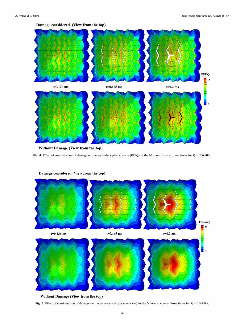
Fig. 4. Effect of consideration of damage on the equivalent plastic strain (PEEQ) in the Miura-ori core at three times for =P 2000 MPa.
Fig. 5. Effect of consideration of damage on the transverse displacement (u3) in the Miura-ori core at three times for =P 2000 MPa.
A. Pydah, R.C. Batra Thin-Walled Structures 129 (2018) 45–57
49
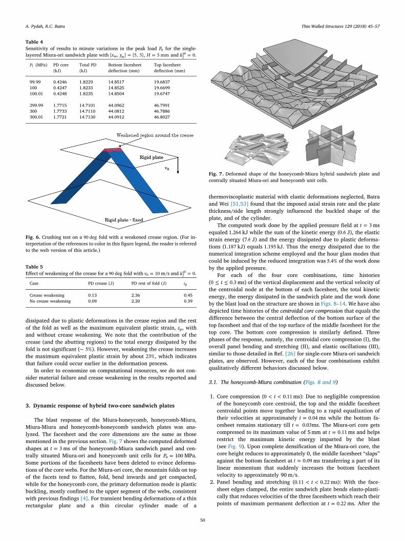
dissipated due to plastic deformations in the crease region and the restof the fold as well as the maximum equivalent plastic strain, ϵp, withand without crease weakening. We note that the contribution of thecrease (and the abutting regions) to the total energy dissipated by thefold is not significant (∼ 5%). However, weakening the crease increasesthe maximum equivalent plastic strain by about 23%, which indicatesthat failure could occur earlier in the deformation process.
In order to economize on computational resources, we do not con-sider material failure and crease weakening in the results reported anddiscussed below.
3. Dynamic response of hybrid two-core sandwich plates
The blast response of the Miura-honeycomb, honeycomb-Miura,Miura-Miura and honeycomb-honeycomb sandwich plates was ana-lyzed. The facesheet and the core dimensions are the same as thosementioned in the previous section. Fig. 7 shows the computed deformedshapes at =t 3 ms of the honeycomb-Miura sandwich panel and cen-trally situated Miura-ori and honeycomb unit cells for =P 1000 MPa.Some portions of the facesheets have been deleted to evince deforma-tions of the core webs. For the Miura-ori core, the mountain folds on topof the facets tend to flatten, fold, bend inwards and get compacted,while for the honeycomb core, the primary deformation mode is plasticbuckling, mostly confined to the upper segment of the webs, consistentwith previous findings [4]. For transient bending deformations of a thinrectangular plate and a thin circular cylinder made of a
thermoviscoplastic material with elastic deformations neglected, Batraand Wei [51,53] found that the imposed axial strain rate and the platethickness/side length strongly influenced the buckled shape of theplate, and of the cylinder.
The computed work done by the applied pressure field at =t 3 msequaled 1.264 kJ while the sum of the kinetic energy (0.6 J), the elasticstrain energy (7.6 J) and the energy dissipated due to plastic deforma-tions (1.187 kJ) equals 1.195 kJ. Thus the energy dissipated due to thenumerical integration scheme employed and the hour glass modes thatcould be induced by the reduced integration was 5.4% of the work doneby the applied pressure.
For each of the four core combinations, time histories( ≤ ≤t0 0.3 ms) of the vertical displacement and the vertical velocity ofthe centroidal node at the bottom of each facesheet, the total kineticenergy, the energy dissipated in the sandwich plate and the work doneby the blast load on the structure are shown in Figs. 8–14. We have alsodepicted time histories of the centroidal core compression that equals thedifference between the central deflection of the bottom surface of thetop facesheet and that of the top surface of the middle facesheet for thetop core. The bottom core compression is similarly defined. Threephases of the response, namely, the centroidal core compression (I), theoverall panel bending and stretching (II), and elastic oscillations (III),similar to those detailed in Ref. [26] for single-core Miura-ori sandwichplates, are observed. However, each of the four combinations exhibitqualitatively different behaviors discussed below.
3.1. The honeycomb-Miura combination (Figs. 8 and 9)
1. Core compression ( < <t0 0.11 ms): Due to negligible compressionof the honeycomb core centroid, the top and the middle facesheetcentroidal points move together leading to a rapid equalization oftheir velocities at approximately =t 0.04 ms while the bottom fa-cesheet remains stationary till =t 0.03ms. The Miura-ori core getscompressed to its maximum value of 5mm at =t 0.11 ms and helpsrestrict the maximum kinetic energy imparted by the blast(see Fig. 9). Upon complete densification of the Miura-ori core, thecore height reduces to approximately 0, the middle facesheet “slaps”against the bottom facesheet at =t 0.09 ms transferring a part of itslinear momentum that suddenly increases the bottom facesheetvelocity to approximately 90m/s.
2. Panel bending and stretching ( < <t0.11 0.22 ms): With the face-sheet edges clamped, the entire sandwich plate bends elasto-plasti-cally that reduces velocities of the three facesheets which reach theirpoints of maximum permanent deflection at =t 0.22 ms. After the
Table 4Sensitivity of results to minute variations in the peak load P0 for the single-layered Miura-ori sandwich plate with =x y{ , } {5, 5}m m , =H 5 mm and =u 0f
pl .
P0 (MPa) PD core(kJ)
Total PD(kJ)
Bottom facesheetdeflection (mm)
Top facesheetdeflection (mm)
99.99 0.4246 1.8229 14.8517 19.6837100 0.4247 1.8233 14.8525 19.6699100.01 0.4248 1.8235 14.8504 19.6747
299.99 1.7715 14.7101 44.0962 46.7991300 1.7733 14.7110 44.0812 46.7886300.01 1.7721 14.7130 44.0912 46.8027
Fig. 6. Crushing test on a 90 deg fold with a weakened crease region. (For in-terpretation of the references to color in this figure legend, the reader is referredto the web version of this article.)
Table 5Effect of weakening of the crease for a 90 deg fold with =v 100 m/s and =u 0f
pl .
Case PD crease (J) PD rest of fold (J) ϵp
Crease weakening 0.13 2.36 0.45No crease weakening 0.09 2.20 0.39
Fig. 7. Deformed shape of the honeycomb-Miura hybrid sandwich plate andcentrally situated Miura-ori and honeycomb unit cells.
A. Pydah, R.C. Batra Thin-Walled Structures 129 (2018) 45–57
50
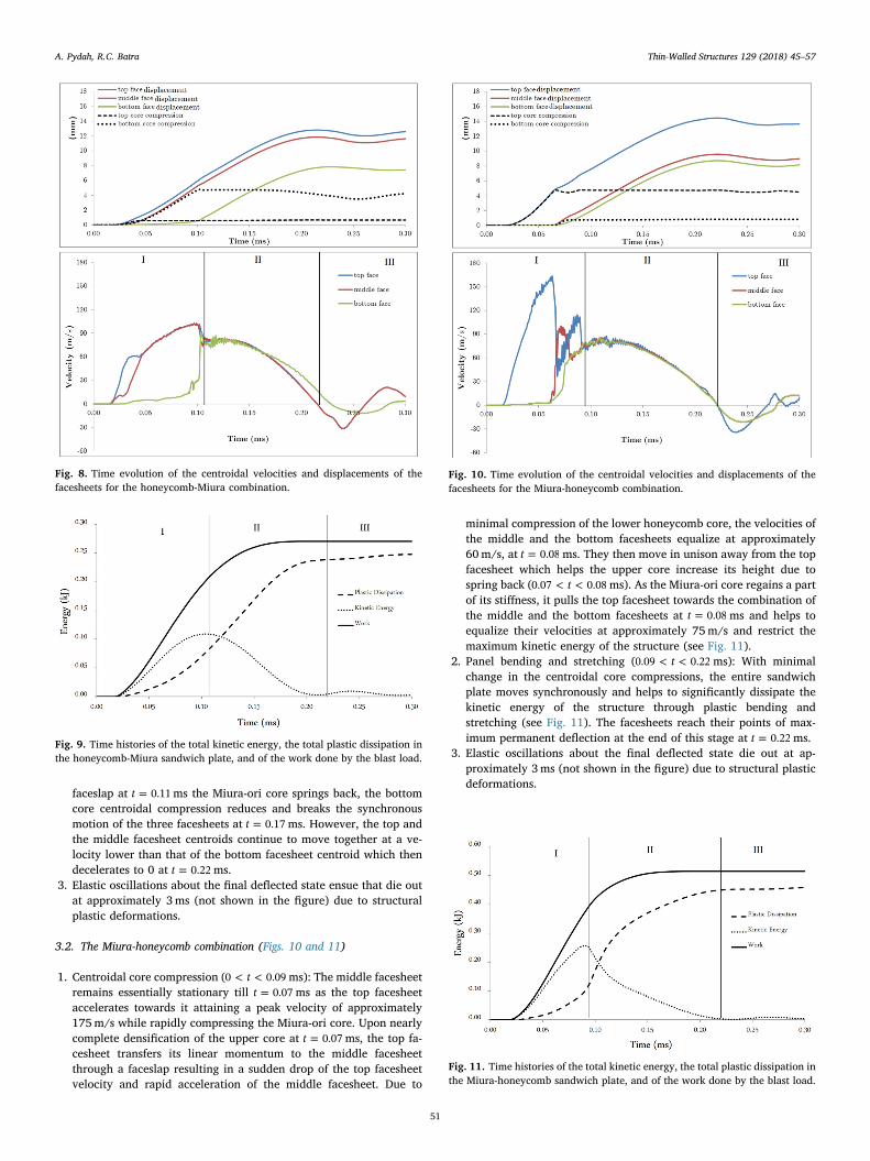
faceslap at =t 0.11ms the Miura-ori core springs back, the bottomcore centroidal compression reduces and breaks the synchronousmotion of the three facesheets at =t 0.17 ms. However, the top andthe middle facesheet centroids continue to move together at a ve-locity lower than that of the bottom facesheet centroid which thendecelerates to 0 at =t 0.22 ms.
3. Elastic oscillations about the final deflected state ensue that die outat approximately 3ms (not shown in the figure) due to structuralplastic deformations.
3.2. The Miura-honeycomb combination (Figs. 10 and 11)
1. Centroidal core compression ( < <t0 0.09 ms): The middle facesheetremains essentially stationary till =t 0.07 ms as the top facesheetaccelerates towards it attaining a peak velocity of approximately175m/s while rapidly compressing the Miura-ori core. Upon nearlycomplete densification of the upper core at =t 0.07 ms, the top fa-cesheet transfers its linear momentum to the middle facesheetthrough a faceslap resulting in a sudden drop of the top facesheetvelocity and rapid acceleration of the middle facesheet. Due to
minimal compression of the lower honeycomb core, the velocities ofthe middle and the bottom facesheets equalize at approximately60m/s, at =t 0.08 ms. They then move in unison away from the topfacesheet which helps the upper core increase its height due tospring back ( < <t0.07 0.08 ms). As the Miura-ori core regains a partof its stiffness, it pulls the top facesheet towards the combination ofthe middle and the bottom facesheets at =t 0.08 ms and helps toequalize their velocities at approximately 75m/s and restrict themaximum kinetic energy of the structure (see Fig. 11).
2. Panel bending and stretching ( < <t0.09 0.22 ms): With minimalchange in the centroidal core compressions, the entire sandwichplate moves synchronously and helps to significantly dissipate thekinetic energy of the structure through plastic bending andstretching (see Fig. 11). The facesheets reach their points of max-imum permanent deflection at the end of this stage at =t 0.22 ms.
3. Elastic oscillations about the final deflected state die out at ap-proximately 3ms (not shown in the figure) due to structural plasticdeformations.
Fig. 8. Time evolution of the centroidal velocities and displacements of thefacesheets for the honeycomb-Miura combination.
Fig. 9. Time histories of the total kinetic energy, the total plastic dissipation inthe honeycomb-Miura sandwich plate, and of the work done by the blast load.
Fig. 10. Time evolution of the centroidal velocities and displacements of thefacesheets for the Miura-honeycomb combination.
Fig. 11. Time histories of the total kinetic energy, the total plastic dissipation inthe Miura-honeycomb sandwich plate, and of the work done by the blast load.
A. Pydah, R.C. Batra Thin-Walled Structures 129 (2018) 45–57
51
Observations from deformations of the two hybrid sandwich platecombinations are listed below:
1. Equalization of velocities of the three facesheets through a combi-nation of the plastic core compression and linear momentumtransfer helps to restrict the maximum kinetic energy of the sand-wich structure.
2. For =P 1000 MPa, the honeycomb core compression is significantlylesser than that of the Miura-ori core. This results in smaller de-flections of the upper-bounding facesheet for the honeycomb coreand of the lower-bounding facesheet for the Miura-ori core.
3. Using the Miura-ori core at the top, i.e., as the core that faces theblast load, can cause complete densification of the core that canresult in faceslaps, high reaction forces at the supports of the face-sheets and a large velocity of the upper facesheet.
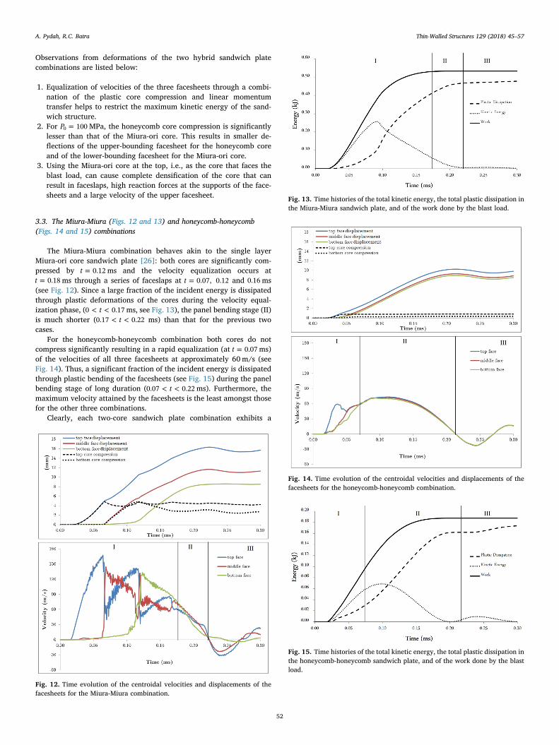
3.3. The Miura-Miura (Figs. 12 and 13) and honeycomb-honeycomb(Figs. 14 and 15) combinations
The Miura-Miura combination behaves akin to the single layerMiura-ori core sandwich plate [26]: both cores are significantly com-pressed by =t 0.12 ms and the velocity equalization occurs at
=t 0.18 ms through a series of faceslaps at =t 0.07, 0.12 and 0.16 ms(see Fig. 12). Since a large fraction of the incident energy is dissipatedthrough plastic deformations of the cores during the velocity equal-ization phase, ( < <t0 0.17 ms, see Fig. 13), the panel bending stage (II)is much shorter ( < <t0.17 0.22 ms) than that for the previous twocases.
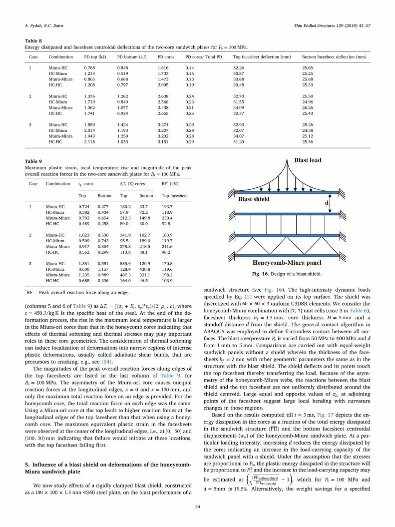
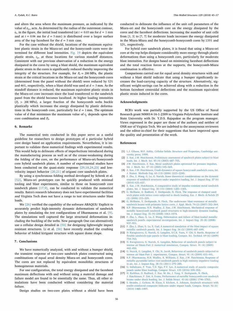
For the honeycomb-honeycomb combination both cores do notcompress significantly resulting in a rapid equalization (at =t 0.07 ms)of the velocities of all three facesheets at approximately 60m/s (seeFig. 14). Thus, a significant fraction of the incident energy is dissipatedthrough plastic bending of the facesheets (see Fig. 15) during the panelbending stage of long duration ( < <t0.07 0.22 ms). Furthermore, themaximum velocity attained by the facesheets is the least amongst thosefor the other three combinations.
Clearly, each two-core sandwich plate combination exhibits a
Fig. 12. Time evolution of the centroidal velocities and displacements of thefacesheets for the Miura-Miura combination.
Fig. 13. Time histories of the total kinetic energy, the total plastic dissipation inthe Miura-Miura sandwich plate, and of the work done by the blast load.
Fig. 14. Time evolution of the centroidal velocities and displacements of thefacesheets for the honeycomb-honeycomb combination.
Fig. 15. Time histories of the total kinetic energy, the total plastic dissipation inthe honeycomb-honeycomb sandwich plate, and of the work done by the blastload.
A. Pydah, R.C. Batra Thin-Walled Structures 129 (2018) 45–57
52

qualitatively different mechanical response to blast loads. In order toestablish the effectiveness of each combination, the influence of the unitcell parameters of the Miura-ori and the honeycomb pattern on plasticdissipation in the cores and the facesheet deflections are investigated inthe next section.
4. Influence of unit cell parameters on the plastic dissipation inthe cores
In our earlier work on the crush dynamics of single-layered Miura-ori sandwich plates [26], we have extensively discussed (see Section 5)the influence of the unit cell parameters of the Miura-ori pattern on thequalitative phases of response of the sandwich plate to blast loads aswell as on the energy dissipation in the Miura-ori core and facesheetscentroidal deflections. It was shown that for a fixed value of side length(a) of rhombic unit cells ( =a b), increasing the dihedral fold angle (θ),which is equivalent to increasing the number of unit cells perpendicularto the corrugation (ym), increases the energy dissipation in the Miura-oricore (Table 3) while not significantly affecting the facesheets centroidaldeflections. It should be noted that the thickness of the facets was ad-justed to maintain a constant core areal density.
We only consider unit cells with =a b( ) and set =H 5 mm. For agiven number of unit cells x y{ , }m m , increasing their number along(across) the corrugation, xm y( )m , reduces the side length a (the acuteangle α); see Eqs. (3) and (4). Once xm is chosen, ym is restricted to begreater than or equal to xm. The thickness ts of the sheet material isadjusted to maintain the relative core density at ρ0.05 m (Eq. (5)). For thesquare honeycomb core, we only consider equal number of webs run-ning in both directions =x y( )m m and adjust thickness tw of the webs tomaintain the relative core density at ρ0.05 m.
In Table 6 we have summarized the 3 unit cell geometries chosen forthe two cores, resulting in 12 different two-core sandwich plates whosedeformations are analyzed till =t 3 ms for blast loads given by Eq. (1)with =P 1000 MPa and 300MPa.
We have summarized in Tables 7 and 8 the energy dissipated in eachcore and their sum, the energy dissipated in a core as a fraction of thetotal energy dissipated in the sandwich structure, and the top and thebottom facesheet centroidal deflections. Based on these results, wemake the following observations:
1. For each of the four combinations, increasing the number of unitcells x y{ , }m m increases the total energy dissipated in the coresthrough plastic deformations (column 5). This change is sig-nificantly more in the Miura-ori core sandwich plates than that inthe honeycomb core sandwich plates. For example, increasing thenumber of unit cells from {3, 3} to {7, 7} for =P 1000 MPa increasesby 135% and 32%, respectively, the energy dissipated by the cores forthe Miura-Miura and the honeycomb-honeycomb combinations.Furthermore, the fraction of the total energy dissipated in thestructure (column 6), which can be viewed as the efficiency of thecores, significantly increases with an increase in the number of unitcells. Increasing the number of unit cells decreases the side length(a) of each fold and increases its stiffness (inversely proportional toa3) and buckling load (inversely proportional to a2). However, tomaintain a constant areal density, the thickness of the webs (tw) isdecreased which causes a reduction in the area moment of inertia
(proportional to tw3 ) and hence, the bending stiffness. Therefore, the
aspect ratio of the webs (a t/ w) plays an important role in the forcerequired to deform them and on the energy dissipated in the core.The same observations hold for =P 3000 MPa, however, the coreefficiency is lesser than that for =P 1000 MPa and the plasticbending deformations of the facesheets help dissipate a greaterfraction of the incident energy.
2. The top core that faces the blast load dissipates a greater amount ofenergy through plastic deformations than the bottom core. For
=P 1000 MPa, a Miura-ori top core dissipates a greater amount ofenergy than a honeycomb top core. However, for =P 3000 MPa, thehoneycomb top core efficiency is greater than that of the Miura-oricore because a larger fraction of the honeycomb webs plasticallybuckle. In terms of the total energy dissipated in the cores, theMiura-honeycomb and the Miura-Miura combinations perform thebest.
3. For =P 1000 MPa, the centroidal deflections of the top and thebottom facesheets in each combination decrease with an increase inthe number of unit cells. However, the centroidal deflections are notsignificantly affected for =P 3000 MPa. As mentioned in the pre-vious section, the top facesheet bounding a honeycomb core hasconsiderably smaller centroidal deflections than a top facesheetbounding a Miura-ori core. Furthermore, using a Miura-ori coreabutting the bottom facesheet helps dissipate a significant fractionof the incident energy and decreases the bottom facesheet centroidaldeflections.
These observations indicate the need to establish a compromise be-tween conflicting structural requirements. For designs based on totalenergy dissipation in the cores, the Miura-honeycomb combination isideal, particularly for =P 1000 MPa. However, from a structural in-tegrity standpoint, the honeycomb-Miura has the least bottom facesheetcentroidal deflection and is second only to the honeycomb-honeycombcombination for the top facesheet centroidal deflection.
In order to assess the reliability of the sandwich plates, in Table 9we have listed the maximum equivalent plastic strain induced in eachcore for the 12 combinations for =P 1000 MPa. We see that the max-imum plastic strain in the Miura-ori cores are larger than that in thecorresponding honeycomb core combinations. As a result, the Miura-ori-based designs may cause a material point to fail at a lower value ofP0 than the honeycomb-based designs.
Assuming that the deformation process is adiabatic and that theentire energy dissipated through plastic deformations is converted toheat, we have estimated the local temperature rise, TΔ r , in each core
Table 6Unit cell geometries of the Miura-ori and honeycomb core models.
Case xm ym Miura-ori Honeycomb
a (mm) α (degrees) θ (degrees) ts (mm) tw (mm)
1 3 3 17.401 74.03 17.39 0.239 0.8342 5 5 11.180 66.42 29.21 0.218 0.5003 7 7 8.719 61.98 40.51 0.190 0.357
Table 7Energy dissipated and facesheet centroidal deflections of the two-core sandwichplates for =P 1000 MPa.
Case Combination PD*
top(kJ)
PDbottom(kJ)
PDcores(kJ)
PDcores/TotalPD
Topfacesheet
Bottomfacesheet
deflection(mm)
deflection(mm)
1 Miura-HC 0.179 0.180 0.360 0.23 14.19 8.94HC-Miura 0.195 0.102 0.297 0.24 12.43 8.32Miura-Miura 0.190 0.130 0.320 0.19 16.11 8.90HC-HC 0.195 0.118 0.313 0.31 9.59 8.93
2 Miura-HC 0.357 0.233 0.590 0.38 13.96 8.36HC-Miura 0.230 0.184 0.414 0.35 12.24 7.56Miura-Miura 0.349 0.200 0.549 0.33 15.58 8.54HC-HC 0.249 0.124 0.373 0.39 9.75 8.45
3 Miura-HC 0.530 0.219 0.749 0.48 13.60 7.71HC-Miura 0.242 0.218 0.460 0.40 12.07 7.50Miura-Miura 0.513 0.238 0.751 0.45 15.59 6.91HC-HC 0.286 0.126 0.412 0.42 9.96 8.31
*PD=Energy dissipated.
A. Pydah, R.C. Batra Thin-Walled Structures 129 (2018) 45–57
53
(columns 5 and 6 of Table 9) as = +T σ E ρ cΔ (( . ϵ )*ϵ )/(2. . )r y t p p m , where=c 450 J/kg K is the specific heat of the steel. At the end of the de-
formation process, the rise in the maximum local temperature is largerin the Miura-ori cores than that in the honeycomb cores indicating thateffects of thermal softening and thermal stresses may play importantroles in these core geometries. The consideration of thermal softeningcan induce localization of deformations into narrow regions of internseplastic deformations, usually called adiabatic shear bands, that areprecursors to cracking; e.g., see [54].
The magnitudes of the peak overall reaction forces along edges ofthe top facesheets are listed in the last column of Table 9, for
=P 1000 MPa. The asymmetry of the Miura-ori core causes unequalreaction forces at the longitudinal edges, =x 0 and =x 100 mm, andonly the maximum total reaction force on an edge is provided. For thehoneycomb core, the total reaction force on each edge was the same.Using a Miura-ori core at the top leads to higher reaction forces at thelongitudinal edges of the top facesheet than that when using a honey-comb core. The maximum equivalent plastic strain in the facesheetswere observed at the center of the longitudinal edges, i.e., at (0, 50) and(100, 50) mm indicating that failure would initiate at these locations,with the top facesheet failing first.
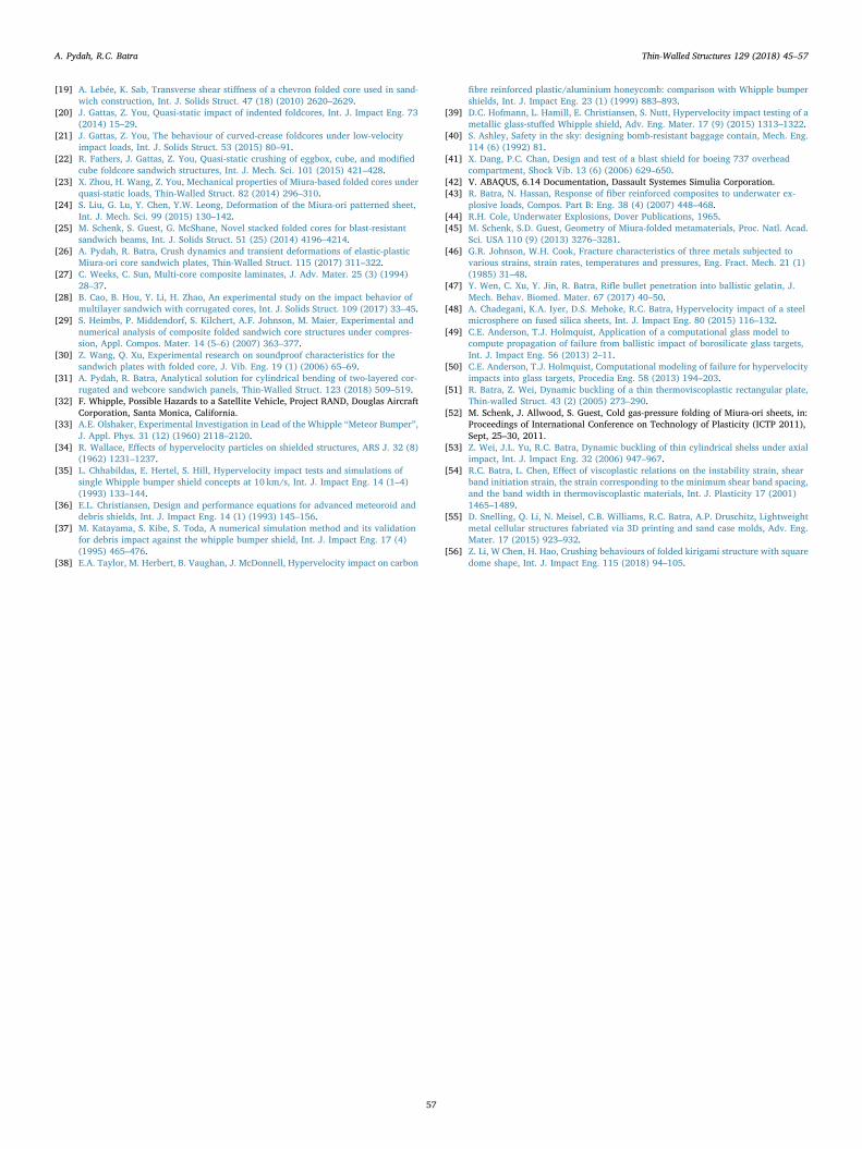
5. Influence of a blast shield on deformations of the honeycomb-Miura sandwich plate
We now study effects of a rigidly clamped blast shield, constructedas a × ×100 100 1.5 mm 4340 steel plate, on the blast performance of a
sandwich structure (see Fig. 16). The high-intensity dynamic loadsspecified by Eq. (1) were applied on its top surface. The shield wasdiscretized with × ×60 60 3 uniform C3D8R elements. We consider thehoneycomb-Miura combination with {7, 7} unit cells (case 3 in Table 6),facesheet thickness =h 1.5 mmf , core thickness =H 5 mm and astandoff distance d from the shield. The general contact algorithm inABAQUS was employed to define frictionless contact between all sur-faces. The blast overpressure P0 is varied from 50MPa to 400MPa and dfrom 1mm to 5mm. Comparisons are carried out with equal-weightsandwich panels without a shield wherein the thickness of the face-sheets =h 2 mmf with other geometric parameters the same as in thestructure with the blast shield. The shield deflects and its points touchthe top facesheet thereby transferring the load. Because of the asym-metry of the honeycomb-Miura webs, the reactions between the blastshield and the top facesheet are not uniformly distributed around theshield centroid. Large equal and opposite values of σzz at adjoiningpoints of the facesheet suggest large local bending with curvaturechanges in those regions.
Based on the results computed till =t 3 ms, Fig. 17 depicts the en-ergy dissipation in the cores as a fraction of the total energy dissipatedin the sandwich structure (PD) and the bottom facesheet centroidaldisplacements (wb) of the honeycomb-Miura sandwich plate. At a par-ticular loading intensity, increasing d reduces the energy dissipated bythe cores indicating an increase in the load-carrying capacity of thesandwich panel with a shield. Under the assumption that the stressesare proportional to P0, the plastic energy dissipated in the structure willbe proportional to P0
2 and the increase in the load-carrying capacity may
be estimated as ⎛⎝
− ⎞⎠
1PDPD
withoutshieldwithshield
, which for =P 1000 MPa and
=d 5mm is 19.5%. Alternatively, the weight savings for a specified
Table 8Energy dissipated and facesheet centroidal deflections of the two-core sandwich plates for =P 3000 MPa.
Case Combination PD top (kJ) PD bottom (kJ) PD cores PD cores/ Total PD Top facesheet deflection (mm) Bottom facesheet deflection (mm)
1 Miura-HC 0.768 0.848 1.616 0.14 32.26 25.65HC-Miura 1.214 0.519 1.733 0.16 30.87 25.25Miura-Miura 0.805 0.668 1.473 0.13 33.68 25.68HC-HC 1.208 0.797 2.005 0.19 29.48 25.33
2 Miura-HC 1.376 1.262 2.638 0.24 32.73 25.50HC-Miura 1.719 0.849 2.568 0.23 31.55 24.96Miura-Miura 1.362 1.077 2.438 0.21 34.09 26.26HC-HC 1.741 0.924 2.665 0.25 30.37 25.43
3 Miura-HC 1.850 1.424 3.274 0.29 32.93 25.26HC-Miura 2.014 1.193 3.207 0.28 32.07 24.58Miura-Miura 1.943 1.259 3.202 0.28 34.07 25.12HC-HC 2.118 1.033 3.151 0.29 31.20 25.36
Table 9Maximum plastic strain, local temperature rise and magnitude of the peakoverall reaction forces in the two-core sandwich plates for =P 1000 MPa.
Case Combination ϵp cores TΔ r (K) cores RF* (kN)
Top Bottom Top Bottom Top facesheet
1 Miura-HC 0.724 0.277 180.2 33.7 193.7HC-Miura 0.382 0.434 57.9 72.2 118.9Miura-Miura 0.792 0.654 212.3 149.8 230.4HC-HC 0.489 0.258 89.0 30.0 92.8
2 Miura-HC 1.023 0.530 341.9 102.7 183.9HC-Miura 0.509 0.743 95.5 189.0 119.7Miura-Miura 0.917 0.804 278.8 218.5 211.6HC-HC 0.562 0.299 113.8 38.1 98.2
3 Miura-HC 1.361 0.581 585.9 120.9 170.8HC-Miura 0.600 1.157 128.4 430.8 119.6Miura-Miura 1.235 0.989 487.3 321.1 198.2HC-HC 0.688 0.336 164.0 46.5 103.9
*RF=Peak overall reaction force along an edge.
Fig. 16. Design of a blast shield.
A. Pydah, R.C. Batra Thin-Walled Structures 129 (2018) 45–57
54

loading intensity can be estimated as −( )1 PDPD
withshieldwithoutshield
, which for the
=d 5 mm case and =P 500 MPa and =P 4000 MPa is 42% and 21%,respectively. Using a blast shield reduces the bottom facesheet cen-troidal deflections (see Fig. 17), particularly at higher loading in-tensities. For example, for =P 3000 MPa and =d 5 mm, the bottomfacesheet centroidal deflections are reduced by 10% when compared tothe panel without the shield. Increasing the standoff distance of the
shield increases the load carrying capacity while reducing the bottomfacesheet centroidal deflections.
In Fig. 18, for =P 1000 MPa, we have shown contour plots of the σzzstress on the outer surface of the top facesheet at four times for
=d 1 mm and =d 5 mm to demonstrate the qualitative difference inthe load transfer between the shield and the top facesheet for the twocases. Increasing d delays the transfer of the blast load to the top fa-cesheet (from =t 0.03 ms for =d 1 mm to =t 0.06 ms for =d 5 mm),
Fig. 17. Energy dissipation in the cores as a fraction of the total energy dis-sipated in the sandwich structure (PD) and the bottom facesheet centroidaldisplacement (wb) of the honeycomb-Miura sandwich plate.
Fig. 18. σzz contour plots on the outer surface of the top facesheet (100*100 mm) of the honeycomb-Miura sandwich plate at four times for =d 1 mm and =d 5 mm.
Fig. 19. Equivalent plastic strain at critical locations in the Miura-ori andhoneycomb cores.
A. Pydah, R.C. Batra Thin-Walled Structures 129 (2018) 45–57
55
and alters the area where the maximum pressure, as indicated by thevalue of σzz, acts. As determined by the radius of the outermost contour,r0, in the figure, the initial load transferred (at =t 0.03 ms for =d 1 mmand at =t 0.06 ms for =d 5 mm) is distributed over a larger surfacearea of the top facesheet for the =d 5 mm case.
For the case without the shield, locations of the maximum equiva-lent plastic strain in the Miura-ori and the honeycomb cores were de-termined for different load intensities. Fig. 19 depicts the equivalentplastic strain, ϵp, at these locations for various standoff distances.Consistent with our previous observation of a reduction in the energydissipated in the cores by using a blast shield, the maximum equivalentplastic strain in the cores is significantly reduced thereby improving theintegrity of the structure. For example, for =P 2000 MPa, the plasticstrain at the critical locations in the Miura-ori and the honeycomb cores(determined from the panel without the shield) were reduced by 52%and 46%, respectively, when a blast shield was used at =d 5 mm. As thestandoff distance is reduced, the maximum equivalent plastic strain inthe Miura-ori core increases since the load transferred to the sandwichpanel from the shield becomes localized. At higher loading intensities( >P 2000 MPa), a larger fraction of the honeycomb webs buckleplastically which increases the energy dissipated by plastic deforma-tions in the honeycomb core, particularly for =d 1 mm. The optimumvalue of d that minimizes the maximum value of ϵp depends upon thecore combination and P0.
6. Remarks
The numerical tests conducted in this paper serve as a usefulguideline for researchers to design prototypes of a particular hybridcore design based on application requirements. Nevertheless, it is im-portant to validate these numerical findings with experimental results.This would help to delineate effects of imperfections introduced duringthe manufacturing process as well as of the crease-weakening duringthe folding of the core, on the performance of Miura-ori/honeycombcore hybrid sandwich plates. A number of experimental studies havebeen conducted on the quasi-static response [29,18,24,23] and low-velocity impact behavior [20,21] of origami core sandwich plates.
By using a synchronous folding method developed by Schenk et al.[52], Miura-ori prototypes can be quickly produced with minimaltooling and blast experiments, similar to those on honeycomb coresandwich plates [17,9], can be conducted to validate the numericalresults. Batra's research laboratory does not have experimental facilitiesand Virginia Tech does not have a range to test structures under blastloads.
We [26] verified the capability of the software ABAQUS/ Explicit toaccurately predict high-intensity dynamic deformations of sandwichplates by simulating the test configurations of Dharmasena et al. [9].The simulations well captured the large structural deformations in-cluding the buckling of the webs. New paragraph One can alternativelyuse a cellular design detailed in [55] for designing lightweight impactresistant structures. Li et al. [56] have recently studied the crushingbehavior of folded kirigami structure with square dome shape.
7. Conclusions
We have numerically analyzed, with and without a bumper shield,the transient response of two-core sandwich plates constructed usingcombinations of equal areal density Miura-ori and honeycomb cores.The cores are not replaced by equivalent monolithic structures ofhomogeneous materials.
For one configuration, the total energy dissipated and the facesheetmaximum deflections with and without using a material damage andfailure model are found to be essentially the same. Thus, all other si-mulations have been conducted without considering the materialfailure.
Design studies on two-core plates without a shield have been
conducted to delineate the influence of the unit cell parameters of theMiura-ori and the honeycomb core on the energy dissipated by thecores and the facesheet deflections. Increasing the number of unit cellsfrom {3, 3} to {7, 7} for moderate loads increases the energy dissipatedin the Miura-Miura and the honeycomb-honeycomb cores by 135% and32%, respectively.
For hybrid core sandwich plates, it is found that using a Miura-oricore at the top helps dissipate considerably more energy through plasticdeformations than using a honeycomb core, particularly for moderateblast intensities. For designs based on minimizing facesheet deflectionsand the total reaction forces at the supports, the honeycomb-Miuracombination is effective.
Comparisons carried out for equal areal density structures with andwithout a blast shield indicate that using a bumper significantly in-creases the load-carrying capacity of the structure. Alternatively, sig-nificant weight-savings can be achieved along with a reduction in thebottom facesheet centroidal deflections and the maximum equivalentplastic strain induced in the cores.
Acknowledgments
RCB's work was partially supported by the US Office of NavalResearch grant N00014-16-1-2309 to Virginia Polytechnic Institute andState University with Dr. Y.D.S. Rajapakse as the program manager.Views expressed in the paper are those of the authors and neither ofONR nor of Virginia Tech. We are indebted to the anonymous reviewersand the editor-in-chief for their suggestions that have improved uponthe quality and presentation of the work.
References
[1] L.J. Gibson, M.F. Ashby, Cellular Solids: Structure and Properties, Cambridge uni-versity press, 1999.
[2] Z. Xue, J.W. Hutchinson, Preliminary assessment of sandwich plates subject to blastloads, Int. J. Mech. Sci. 45 (4) (2003) 687–705.
[3] J.W. Hutchinson, Z. Xue, Metal sandwich plates optimized for pressure impulses,Int. J. Mech. Sci. 47 (4) (2005) 545–569.
[4] Z. Xue, J.W. Hutchinson, Crush dynamics of square honeycomb sandwich cores, Int.J. Numer. Methods Eng. 65 (13) (2006) 2221–2245.
[5] F. Zhu, Z. Wang, G. Lu, G. Nurick, Some theoretical considerations on the dynamicresponse of sandwich structures under impulsive loading, Int. J. Impact Eng. 37 (6)(2010) 625–637.
[6] Z. Xue, J.W. Hutchinson, A comparative study of impulse-resistant metal sandwichplates, Int. J. Impact Eng. 30 (10) (2004) 1283–1305.
[7] G. McShane, D. Radford, V. Deshpande, N. Fleck, The response of clamped sand-wich plates with lattice cores subjected to shock loading, Eur. J. Mech.-A/Solids 25(2) (2006) 215–229.
[8] G. McShane, V. Deshpande, N. Fleck, The underwater blast resistance of metallicsandwich beams with prismatic lattice cores, J. Appl. Mech. 74 (2) (2007) 352–364.
[9] K.P. Dharmasena, H.N. Wadley, Z. Xue, J.W. Hutchinson, Mechanical response ofmetallic honeycomb sandwich panel structures to high-intensity dynamic loading,Int. J. Impact Eng. 35 (9) (2008) 1063–1074.
[10] F. Zhu, L. Zhao, G. Lu, Z. Wang, Deformation and failure of blast-loaded metallicsandwich panels- experimental investigations, Int. J. Impact Eng. 35 (8) (2008)937–951.
[11] F. Zhu, L. Zhao, G. Lu, E. Gad, A numerical simulation of the blast impact of squaremetallic sandwich panels, Int. J. Impact Eng. 36 (5) (2009) 687–699.
[12] D. Karagiozova, G. Nurick, G. Langdon, S.C.K. Yuen, Y. Chi, S. Bartle, Response offlexible sandwich-type panels to blast loading, Compos. Sci. Technol. 69 (6) (2009)754–763.
[13] D. Karagiozova, G. Nurick, G. Langdon, Behaviour of sandwich panels subject tointense air blasts-Part 2: numerical simulation, Compos. Struct. 91 (4) (2009)442–450.
[14] G. Nurick, G. Langdon, Y. Chi, N. Jacob, Behaviour of sandwich panels subjected tointense air blast-Part 1: experiments, Compos. Struct. 91 (4) (2009) 433–441.
[15] K.P. Dharmasena, H.N. Wadley, K. Williams, Z. Xue, J.W. Hutchinson, Response ofmetallic pyramidal lattice core sandwich panels to high intensity impulsive loadingin air, Int. J. Impact Eng. 38 (5) (2011) 275–289.
[16] G. Imbalzano, P. Tran, T.D. Ngo, P.V. Lee, A numerical study of auxetic compositepanels under blast loadings, Compos. Struct. 135 (2016) 339–352.
[17] H. Rathbun, D. Radford, Z. Xue, M. He, J. Yang, V. Deshpande, N. Fleck,J. Hutchinson, F. Zok, A. Evans, Performance of metallic honeycomb-core sandwichbeams under shock loading, Int. J. Solids Struct. 43 (6) (2006) 1746–1763.
[18] S. Heimbs, J. Cichosz, M. Klaus, S. Kilchert, A. Johnson, Sandwich structures withtextile-reinforced composite foldcores under impact loads, Compos. Struct. 92 (6)(2010) 1485–1497.
A. Pydah, R.C. Batra Thin-Walled Structures 129 (2018) 45–57
56
[19] A. Lebée, K. Sab, Transverse shear stiffness of a chevron folded core used in sand-wich construction, Int. J. Solids Struct. 47 (18) (2010) 2620–2629.
[20] J. Gattas, Z. You, Quasi-static impact of indented foldcores, Int. J. Impact Eng. 73(2014) 15–29.
[21] J. Gattas, Z. You, The behaviour of curved-crease foldcores under low-velocityimpact loads, Int. J. Solids Struct. 53 (2015) 80–91.
[22] R. Fathers, J. Gattas, Z. You, Quasi-static crushing of eggbox, cube, and modifiedcube foldcore sandwich structures, Int. J. Mech. Sci. 101 (2015) 421–428.
[23] X. Zhou, H. Wang, Z. You, Mechanical properties of Miura-based folded cores underquasi-static loads, Thin-Walled Struct. 82 (2014) 296–310.
[24] S. Liu, G. Lu, Y. Chen, Y.W. Leong, Deformation of the Miura-ori patterned sheet,Int. J. Mech. Sci. 99 (2015) 130–142.
[25] M. Schenk, S. Guest, G. McShane, Novel stacked folded cores for blast-resistantsandwich beams, Int. J. Solids Struct. 51 (25) (2014) 4196–4214.
[26] A. Pydah, R. Batra, Crush dynamics and transient deformations of elastic-plasticMiura-ori core sandwich plates, Thin-Walled Struct. 115 (2017) 311–322.
[27] C. Weeks, C. Sun, Multi-core composite laminates, J. Adv. Mater. 25 (3) (1994)28–37.
[28] B. Cao, B. Hou, Y. Li, H. Zhao, An experimental study on the impact behavior ofmultilayer sandwich with corrugated cores, Int. J. Solids Struct. 109 (2017) 33–45.
[29] S. Heimbs, P. Middendorf, S. Kilchert, A.F. Johnson, M. Maier, Experimental andnumerical analysis of composite folded sandwich core structures under compres-sion, Appl. Compos. Mater. 14 (5–6) (2007) 363–377.
[30] Z. Wang, Q. Xu, Experimental research on soundproof characteristics for thesandwich plates with folded core, J. Vib. Eng. 19 (1) (2006) 65–69.
[31] A. Pydah, R. Batra, Analytical solution for cylindrical bending of two-layered cor-rugated and webcore sandwich panels, Thin-Walled Struct. 123 (2018) 509–519.
[32] F. Whipple, Possible Hazards to a Satellite Vehicle, Project RAND, Douglas AircraftCorporation, Santa Monica, California.
[33] A.E. Olshaker, Experimental Investigation in Lead of the Whipple “Meteor Bumper”,J. Appl. Phys. 31 (12) (1960) 2118–2120.
[34] R. Wallace, Effects of hypervelocity particles on shielded structures, ARS J. 32 (8)(1962) 1231–1237.
[35] L. Chhabildas, E. Hertel, S. Hill, Hypervelocity impact tests and simulations ofsingle Whipple bumper shield concepts at 10 km/s, Int. J. Impact Eng. 14 (1–4)(1993) 133–144.
[36] E.L. Christiansen, Design and performance equations for advanced meteoroid anddebris shields, Int. J. Impact Eng. 14 (1) (1993) 145–156.
[37] M. Katayama, S. Kibe, S. Toda, A numerical simulation method and its validationfor debris impact against the whipple bumper shield, Int. J. Impact Eng. 17 (4)(1995) 465–476.
[38] E.A. Taylor, M. Herbert, B. Vaughan, J. McDonnell, Hypervelocity impact on carbon
fibre reinforced plastic/aluminium honeycomb: comparison with Whipple bumpershields, Int. J. Impact Eng. 23 (1) (1999) 883–893.
[39] D.C. Hofmann, L. Hamill, E. Christiansen, S. Nutt, Hypervelocity impact testing of ametallic glass-stuffed Whipple shield, Adv. Eng. Mater. 17 (9) (2015) 1313–1322.
[40] S. Ashley, Safety in the sky: designing bomb-resistant baggage contain, Mech. Eng.114 (6) (1992) 81.
[41] X. Dang, P.C. Chan, Design and test of a blast shield for boeing 737 overheadcompartment, Shock Vib. 13 (6) (2006) 629–650.
[42] V. ABAQUS, 6.14 Documentation, Dassault Systemes Simulia Corporation.[43] R. Batra, N. Hassan, Response of fiber reinforced composites to underwater ex-
plosive loads, Compos. Part B: Eng. 38 (4) (2007) 448–468.[44] R.H. Cole, Underwater Explosions, Dover Publications, 1965.[45] M. Schenk, S.D. Guest, Geometry of Miura-folded metamaterials, Proc. Natl. Acad.
Sci. USA 110 (9) (2013) 3276–3281.[46] G.R. Johnson, W.H. Cook, Fracture characteristics of three metals subjected to
various strains, strain rates, temperatures and pressures, Eng. Fract. Mech. 21 (1)(1985) 31–48.
[47] Y. Wen, C. Xu, Y. Jin, R. Batra, Rifle bullet penetration into ballistic gelatin, J.Mech. Behav. Biomed. Mater. 67 (2017) 40–50.
[48] A. Chadegani, K.A. Iyer, D.S. Mehoke, R.C. Batra, Hypervelocity impact of a steelmicrosphere on fused silica sheets, Int. J. Impact Eng. 80 (2015) 116–132.
[49] C.E. Anderson, T.J. Holmquist, Application of a computational glass model tocompute propagation of failure from ballistic impact of borosilicate glass targets,Int. J. Impact Eng. 56 (2013) 2–11.
[50] C.E. Anderson, T.J. Holmquist, Computational modeling of failure for hypervelocityimpacts into glass targets, Procedia Eng. 58 (2013) 194–203.
[51] R. Batra, Z. Wei, Dynamic buckling of a thin thermoviscoplastic rectangular plate,Thin-walled Struct. 43 (2) (2005) 273–290.
[52] M. Schenk, J. Allwood, S. Guest, Cold gas-pressure folding of Miura-ori sheets, in:Proceedings of International Conference on Technology of Plasticity (ICTP 2011),Sept, 25–30, 2011.
[53] Z. Wei, J.L. Yu, R.C. Batra, Dynamic buckling of thin cylindrical shelss under axialimpact, Int. J. Impact Eng. 32 (2006) 947–967.
[54] R.C. Batra, L. Chen, Effect of viscoplastic relations on the instability strain, shearband initiation strain, the strain corresponding to the minimum shear band spacing,and the band width in thermoviscoplastic materials, Int. J. Plasticity 17 (2001)1465–1489.
[55] D. Snelling, Q. Li, N. Meisel, C.B. Williams, R.C. Batra, A.P. Druschitz, Lightweightmetal cellular structures fabriated via 3D printing and sand case molds, Adv. Eng.Mater. 17 (2015) 923–932.
[56] Z. Li, W Chen, H. Hao, Crushing behaviours of folded kirigami structure with squaredome shape, Int. J. Impact Eng. 115 (2018) 94–105.
A. Pydah, R.C. Batra Thin-Walled Structures 129 (2018) 45–57
57


