
BLADDER ACCUMULATORS LOW PRESSUR …epg.eu/wp-content/uploads/2014/07/3.4-Bladder...BLADDER...
16
3.4.2 HYDRAULIC SYMBOL EPE ITALIANA s.r.l. - Viale Spagna,112 • 20093 Cologno Monzese (Mi) Italy Tel.: +39 02 25459028 • Fax: +39 02 25 25459773 • E-mail: [email protected] • Internet: www.epeitaliana.it 1 3.4.1 TECHNICAL DATA MAX OPERATING PRESSURE (PS): 60 bar PRESSURE TEST (PT): 1.43 x PS NOMINAL CAPACITIES: ASBL: 0.7 - 1 - 1.5 - 3 - 5 – 10 – 15 – 20 – 25 – 35 - 55 litres ASBT: 1 - 1.5 - 3 - 5 – 10 – 15 – 20 – 25 – 35 - 55 litres WORKING TEMPERATURE: -40 ÷ +150 ℃ FLUID VISCOSITY RANGE: 10 ÷ 400 cSt RECOMMENDED VISCOSITY: 36 cSt FLUID CONTAMINATION DEGREE: class 21/19/16 according to ISO 4406/99 BODY MATERIAL: - carbon steel shell painted with rust inhibitor RAL 8012 - nickel coating 25 - 40 µ - stainless steel AISI 316L VALVES MATERIAL: - phosphated or galvanized carbon steel in compliance with Directive 2002/95/EC (RoHS) to resist to corrosion - stainless steel AISI 316L - nickel coating 25-40 μ BLADDER MATERIAL: - P = Nitrile rubber (NBR) - F = Low temp. nitrile rubber - H = Nitril for hydrocarbons - K = Hydrogenated nitrile (HNBR) - B = Butyl (IIR) - E = Ethylene-propylene (EPDM) - N = Chloroprene (Neoprene) - Y = Epichlorohydrin (ECO) - V = Fluorocarbon (FPM) See Table 3.4c and/or Chapter 1.5 GAS VALVE CONNECTION: see Table 3.4db - 3.4dd FLUID PORT CONNECTION: - see Table 3.4db - 3.4dd - 3.4eb 3.4ec - 3.4fb FLOW RATE: see Table 3.4db - 3.4dd WEIGHT: see Table 3.4db - 3.4dd BLADDER ACCUMULATORS LOW PRESSUR LIQUID SEPARATOR type ASBL and TRANSFER type ASBT E 01-12 3.4 3.4a 3.4b
Transcript of BLADDER ACCUMULATORS LOW PRESSUR …epg.eu/wp-content/uploads/2014/07/3.4-Bladder...BLADDER...
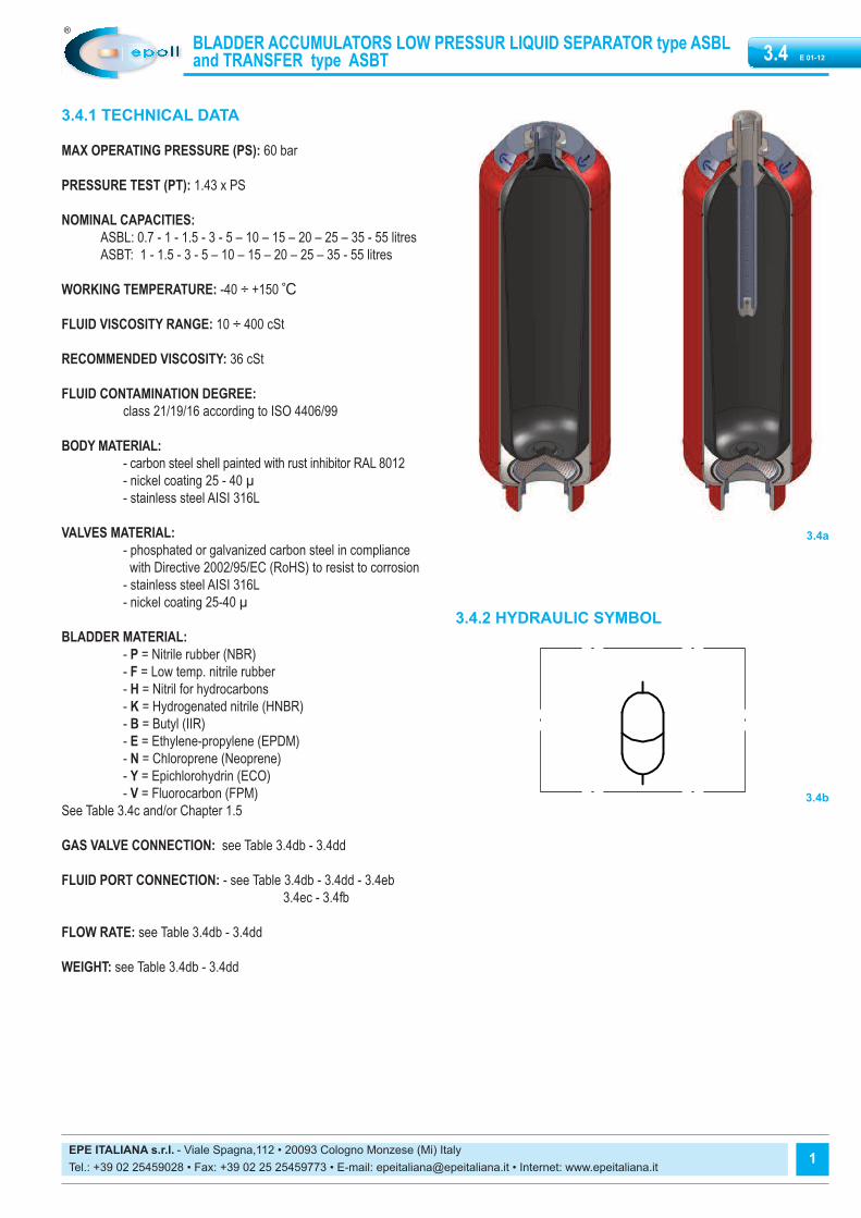
3.4.2 HYDRAULIC SYMBOL
EPE ITALIANA s.r.l. - Viale Spagna,112 • 20093 Cologno Monzese (Mi) Italy Tel.: +39 02 25459028 • Fax: +39 02 25 25459773 • E-mail: [email protected] • Internet: www.epeitaliana.it
1
3.4.1 TECHNICAL DATA
MAX OPERATING PRESSURE (PS): 60 bar
PRESSURE TEST (PT): 1.43 x PS
NOMINAL CAPACITIES:ASBL: 0.7 - 1 - 1.5 - 3 - 5 – 10 – 15 – 20 – 25 – 35 - 55 litresASBT: 1 - 1.5 - 3 - 5 – 10 – 15 – 20 – 25 – 35 - 55 litres
WORKING TEMPERATURE: -40 ÷ +150 ℃
FLUID VISCOSITY RANGE: 10 ÷ 400 cSt
RECOMMENDED VISCOSITY: 36 cSt
FLUID CONTAMINATION DEGREE: class 21/19/16 according to ISO 4406/99
BODY MATERIAL:- carbon steel shell painted with rust inhibitor RAL 8012- nickel coating 25 - 40 µ- stainless steel AISI 316L
VALVES MATERIAL:- phosphated or galvanized carbon steel in compliance
with Directive 2002/95/EC (RoHS) to resist to corrosion- stainless steel AISI 316L- nickel coating 25-40 μ
BLADDER MATERIAL:- P = Nitrile rubber (NBR)- F = Low temp. nitrile rubber- H = Nitril for hydrocarbons- K = Hydrogenated nitrile (HNBR)- B = Butyl (IIR)- E = Ethylene-propylene (EPDM)- N = Chloroprene (Neoprene)- Y = Epichlorohydrin (ECO)- V = Fluorocarbon (FPM)
See Table 3.4c and/or Chapter 1.5
GAS VALVE CONNECTION: see Table 3.4db - 3.4dd
FLUID PORT CONNECTION: - see Table 3.4db - 3.4dd - 3.4eb3.4ec - 3.4fb
FLOW RATE: see Table 3.4db - 3.4dd
WEIGHT: see Table 3.4db - 3.4dd
BLADDER ACCUMULATORS LOW PRESSUR LIQUID SEPARATOR type ASBL and TRANSFER type ASBT E 01-123.4
3.4a
3.4b

EPE ITALIANA s.r.l. - Viale Spagna,112 • 20093 Cologno Monzese (Mi) Italy Tel.: +39 02 25459028 • Fax: +39 02 25 25459773 • E-mail: [email protected] • Internet: www.epeitaliana.it
BLADDER ACCUMULATORS LOW PRESSUR LIQUID SEPARATOR type ASBL and TRANSFER type ASBT E 01-123.4
2
3.4.3 “ASBL and ASBT” BLADDER ADVANTAGES- dirt tolerant- light weight- compact- simple construction- quick response- works well on water, low lubricity fluids- quick, easy installation- low cost
3.4.4 DESCRIPTIONBladder low pressure ASBL and ASBT type accumulators consist of awelded cylindrical pressure vessel made of steel.The accumulators are subdivided into a gas and fluid side by an elasticbladder mounted in the interior of the vessel.In the ASBL type, the liquid is also inside the bladder.The transfer accumulator ASBT type is designed especially for connec-ting to nitrogen bottle. A diffuser rod prevents damages to the bladderwhen the accumulator works.Nitrogen bottle used as back-ups increase the gas volume in theaccumulator. This means that smaller accumulators can be used for thesame gas volume and costs can be reduced.When the fluid is pressed into the accumulator, the gas in the bladder iscompressed and hence the pressure increased. The gas volume reducesand on the fluid side, the fluid can flow into the accumulator. As soon asthe pressure on the fluid side falls below the gas pressure, the accumu-lator is emptied.Oil valve is provided in the oil port of the bladder-type accumulator andcloses when the pressure on the gas side is higher than the one on thefluid side. This prevents draining of the bladder into the oil channel andthus the bladder from being destroyed.When the minimum operating pressure is reached, a small oil volume isto be maintained between the bladder and the fluid volume (approx. 10%of the nominal capacity of the hydraulic accumulator), in order that thebladder does not hit the valve during every expansion process.The gas valve body of ASBL type accumulator is complete with anti-ex-trusion in addition to the rubber washer and locknut. The gas valve body of ASBT type accumulator is complete with diffuserrod in addition to the rubber washer and locknut. These parts can be replaced separately.The nameplate shows the technical data and features of the hydraulicaccumulator.
3.4.5 EUROPE MARKETAll hydraulic accumulators are pressure vessels and are subject to thenational regulations and directives, valid at the place of installation.Bladder accumulator type ASBL e ASBT, up to and including 1 liter mustnot be CE marked.For bladder accumulator type ASBL e ASBT, greater than 1 liter, everyshipping batch is complete of a conformity declaration and instruction ofuse and maintenance and/or all documents requested.All vessel categories (see Table 3.4db, 3.4dd) must be protected bymeans of a pressure relief valve in accordance with Directive 97/23/EC.
3.4.6 ACCESSORIESFor additional cylinders, see Section 6 For support equipment, see Cap. 7For gas side’s safety equipment, see Cap. 8For fluid side’s safety equipment, see Cap. 9 For pre-loading and charging set, see Cap. 11For other components, see Cap. 12

Codeletter Polymer ISO
Temperaturerange (°C) Some of the liquids compatible with the polymer
P Standard nitrile (Perburan) NBR -20 ÷ +80 Aliphatic hydrocarbons (propane, butane, gasoline, oils, mineral grea-ses, diesel fuel, fuel oil, kerosene), mineral greases and oils, HFA -HFB - HFC fluids, many dilute acids, alkalis, saline solutions, water,water glycol.
F Low temperature nitrile NBR -40 ÷ +70 The same as with standard nitrile + a number of different types ofFreon. (This contains less acrylonitrile than the standard and is there-fore more suitable for low temperatures, but its chemical resistance isslightly lower).
H Nitrile for hydrocarbons NBR -10 ÷ +90 Regular and premium grade slightly aromatic gasoline (and all the li-quids for standard nitrile).
K Hydrogenated nitrile HNBR -30 ÷ +130 The same as with standard nitrile but with excellent performance athigh and low temperatures.
B Butyl IIR -30 ÷ +100 Hot water up to 100°C, glycol-based brake fluids, many acids andbases, salt solutions, polar solvents such as alcohols, ketones andesters, polyglycol-based hydraulic fluids (HFC fluids) and bases ofesters of phosphoric acid (HFD-R fluids), silicone oils and greases,Skydol 500 and 7000, resistance to ozone, aging and weathering.
E Ethylene-Propylene EPDM -30 ÷ +100 Hot water up to 100°C, glycol-based brake fluids, many organic andinorganic acids, detergents, solutions of sodium and potassium, pho-sphate ester-based hydraulic fluids, (HFD-R), silicone oils and greases,many polar solvents (alcohol, ketones, esters), Skydrol 500 and 7000,resistance to ozone, aging and weathering.
N Chloroprene (Neoprene) CR -30 ÷ +100 Mineral oils of paraffin, silicone oils and greases, water and aqueoussolutions, refrigerants (ammonia, carbon dioxide, Freon), naphthenicmineral oils, low molecular aliphatic hydrocarbons (propane, butane,fuel), brake fluids based on glycol, better resistance to ozone, weathe-ring and aging compared to NBR rubber.
Y Epichloridrin ECO -30 ÷ +110 Mineral oils and greases, aliphatic hydrocarbons (propane, butane andgasoline), silicone oils and greases, water at room temperature, resi-stance to ozone, aging and weathering.
V Fluorocarbon FPM -10 ÷ +150 Mineral oils and greases, non-flammable fluids of HFD group, silicone oilsand greases, animal and vegetable oils and greases, aliphatic hydrocar-bons (gasoline, butane, propane, natural gas), aromatics hydrocarbons(benzene, toluene), chlorinated hydrocarbons (Tetrachloroethylene, car-bon tetrachloride), fuel (regular, super and containing methanol), excellentresistance to ozone, weathering and aging.
BLADDER ACCUMULATORS LOW PRESSUR LIQUID SEPARATOR type ASBL and TRANSFER type ASBT E 01-123.4
EPE ITALIANA s.r.l. - Viale Spagna,112 • 20093 Cologno Monzese (Mi) Italy Tel.: +39 02 25459028 • Fax: +39 02 25 25459773 • E-mail: [email protected] • Internet: www.epeitaliana.it
3
For other hydraulic fluid and/or temperatures, please consult us.
3.4.7 BLADDER-TEMPERATURE-LIQUID COMPATIBILITYWhen selecting the accumulator variant, pay attention to the following non-binding notes with regard to hydraulic fluid, bladder material and the per-missive temperature range. (see Section 1.5)
3.4c

EPE ITALIANA s.r.l. - Viale Spagna,112 • 20093 Cologno Monzese (Mi) Italy Tel.: +39 02 25459028 • Fax: +39 02 25 25459773 • E-mail: [email protected] • Internet: www.epeitaliana.it
BLADDER ACCUMULATORS LOW PRESSUR LIQUID SEPARATOR type ASBL and TRANSFER type ASBT E 01-123.4
4
3.4.8 ORDER CODE
Special variants upon requestVersioni speciali su richiesta
Connection gas sideCapacity 0.7 ÷ 5 l = G2Capacity 10 ÷ 55 l = G6
SeriesBladder accumulator low pressureliquid separator = ASBLBladder accumulator lowpressure transfer = ASBT
Nominal capacity 0.7 lt = 0.71 lt = 11.5 lt = 1.53 lt = 35 lt = 5
10 lt = 1015 lt = 1520 lt = 2025 lt = 2535 lt = 3555 lt = 55
Bladder material Nitrile rubber (NBR) = PNitrile for low temp. = FNitril for hydrocarbons = HHydrogenated nitrile (HNBR) = KButyl (IIR) = BEthylene-propylene (EPDM) = EChloroprene (Neoprene) = NEpichlorohydrin (ECO) = YFluorocarbon (FPM) = V
Body materialCarbon steel = CNickel coated carbon steel 25 µ = NNickel coated carbon steel 40 µ = MStainless steel = X
ASBL 25 P 25 X R G10 G6 - 8 - X 1 X 0 F6
Max working pressure (PS)
See the table on front page
Other variants
See the table on front page
Fluid valve material Carbon steel = CNickel coated carbon steel 25 µ = NNickel coated carbon steel 40 µ = MStainless steel = X
Variants of fluid side Standard = 0Adapter in stainless steel (R) = 1Other numbers/variants to be requested EPE
Gas valve material Carbon steel = CNickel coated carbon steel 25 µ = NNickel coated carbon steel 40 µ = MStainless steel = X
Variants of gas side Standard = 0Only cap in stainless steel = 1Brass nameplate = 2Other numbers/variants to be requested EPE
Fluid port connection0.7÷55 l BSP ISO 228 with chamfer for OR (std) = A0.7÷55 l adapter * = R* assembled on the fluid valve connection type A
Test and certification
Factory testing = 0TR (Russia) = 1ML (China) = 3PED97/23/EC(for capacitiesgreater than 1 l) = 8ATEX 94/9EC = 9RTN Passport (Ukraine) = 11Algeria passport = 12Standard regulation (NR13) (Brazil) = 13Tunisia passport = 14Dimension of the
connection fluid or 7+8 tableSee the table on front page
1 2 3 4 5 6 7 - 8 9 10 11 12 13 14 15
1
2
3
4
5
6
7 - 8
15
14
13
12
11
10
9

BLADDER ACCUMULATORS LOW PRESSUR LIQUID SEPARATOR type ASBL and TRANSFER type ASBT E 01-123.4
EPE ITALIANA s.r.l. - Viale Spagna,112 • 20093 Cologno Monzese (Mi) Italy Tel.: +39 02 25459028 • Fax: +39 02 25 25459773 • E-mail: [email protected] • Internet: www.epeitaliana.it
5
Other variants
Rupture disc set at xxx bar, laterally on AST = Rxxx (see Section…)Needle Valve of ¼” BSP, laterally on AST = EG2Flushing with degree of contamination ≤ x = Fx75-80 μ thick polyurethane paint with colour to be specified = WxxxOff-shore paint with colour to be specified = ZxxxNORSOK System 1 paint with colour to be specified = K1NORSOK System 7 paint with colour to be specified = K7other variants upon request
Max working pressure (PS)
Capacity litres Carbon steel Stainless steel
0.7÷ 5 10 ÷ 55
6030 - 50
(other pressure relatedto connections B or U)
4025 - 50
Fluid port connection
For ASxx 0.7÷55BSP ISO 228 with chamfer for OR (std) = A
For ASxx 0.2 BSP ISO 228 (std) = GFor ASxx 3÷55 Metric = MFor ASxx 0.7÷55 NPT-F = PFor ASxx 3÷55 internal thread SAE = SFor ASxx 3÷55 adapter for flange SAE 3000 Psi = LFor ASxx 3÷55 adapter for flange SAE 6000 Psi = HFor ASxx 0.7÷55 flange ANSI = BFor ASxx 0.7÷55 flange UNI = UFor ASxx 0.7÷55 square flange = QFor ASxx 0.7÷55 adapter * = R* assembled on the fluid valve connection type A
Dimension of the fluid connection For the type of connection:
A (0.7 ÷ 5 l) 2” = 9(3 ÷ 5 l) 2” 1/2 = 10(10 ÷ 55 l) 4” = 13
B (0.7÷55 l) DIMENSION/RATINGFormer. 1” ANSI 150 = 1/150 (Pmax = 20 bar)U (0.7÷55 l) DN/PNFormer. DN50 PN16 = 50/16 (Pmax = 16 bar)
R (0.7÷55 l) Blind = 0R (0.7÷55 l) internal threadBSP ISO 228 = G* NPT-F = P*BSPT = N*
SAE = S* Metric = M*
*Variant in table 8
Special variants upon request
Dimension in inch - No.of pitch for inch
Diameter/pitch
4
6 15
7
Dimension1/8“ = 11/4“ = 23/8“ = 31/2“ = 4
8
3/4“ = 51“ = 61“ ¼“ = 71“ ½“ = 8
2“ = 92“ ½“ = 103“ = 113“ ½“ = 12
EPE ITALIANA s.r.l. - Viale Spagna,112 • 20093 Cologno Monzese (Mi) Italy Tel.: +39 02 25459028 • Fax: +39 02 25 25459773 • E-mail: [email protected] • Internet: www.epeitaliana.it
BLADDER ACCUMULATORS LOW PRESSUR LIQUID SEPARATOR type ASBL and TRANSFER type ASBT E 01-123.4
6
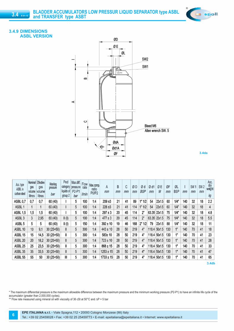
* The maximum differential pressure is the maximum allowable difference between the maximum pressure and the minimum working pressure (P2-P1) to have an infinite life cycle of theaccumulator (greater than 2,000,000 cycles).** Flow rate measured using mineral oil with viscosity of 36 cSt at 50°C and ∆P = 5 bar
3.4.9 DIMENSIONSASBL VERSION
3.4da
3.4db

E 01-123.4
EPE ITALIANA s.r.l. - Viale Spagna,112 • 20093 Cologno Monzese (Mi) Italy Tel.: +39 02 25459028 • Fax: +39 02 25 25459773 • E-mail: [email protected] • Internet: www.epeitaliana.it
7
* The maximum differential pressure is the maximum allowable difference between the maximum pressure and the minimum working pressure (P2-P1) to have an infinite life cycle of theaccumulator (greater than 2,000,000 cycles).** Flow rate measured using mineral oil with viscosity of 36 cSt at 50°C and ∆P = 5 bar
ASBT VERSION
3.4dc
3.4dd
BLADDER ACCUMULATORS LOW PRESSUR LIQUID SEPARATOR type ASBL and TRANSFER type ASBT

EPE ITALIANA s.r.l. - Viale Spagna,112 • 20093 Cologno Monzese (Mi) Italy Tel.: +39 02 25459028 • Fax: +39 02 25 25459773 • E-mail: [email protected] • Internet: www.epeitaliana.it
8
BLADDER ACCUMULATORS LOW PRESSUR LIQUID SEPARATOR type ASBL and TRANSFER type ASBT E 01-123.4
3.4.9.1 FLANGE CONNECTION TYPE ANSI / UNI DIN (B/U)
Fig. I Fig. II 3.4ea
3.4eb
3.4ec
EPE ITALIANA s.r.l. - Viale Spagna,112 • 20093 Cologno Monzese (Mi) Italy Tel.: +39 02 25459028 • Fax: +39 02 25 25459773 • E-mail: [email protected] • Internet: www.epeitaliana.it
9
E 01-123.4
3.4fa
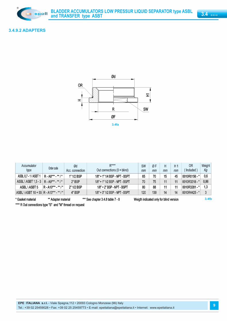
3.4.9.2 ADAPTERS
3.4fb
BLADDER ACCUMULATORS LOW PRESSUR LIQUID SEPARATOR type ASBL and TRANSFER type ASBT

EPE ITALIANA s.r.l. - Viale Spagna,112 • 20093 Cologno Monzese (Mi) Italy Tel.: +39 02 25459028 • Fax: +39 02 25 25459773 • E-mail: [email protected] • Internet: www.epeitaliana.it
10
BLADDER ACCUMULATORS LOW PRESSUR LIQUID SEPARATOR type ASBL and TRANSFER type ASBT E 01-123.4
3.3ga
3.3gb
3.4.10. SPARE PARTS CODE ASBL VERSION
EPE ITALIANA s.r.l. - Viale Spagna,112 • 20093 Cologno Monzese (Mi) Italy Tel.: +39 02 25459028 • Fax: +39 02 25 25459773 • E-mail: [email protected] • Internet: www.epeitaliana.it
11
E 01-123.4
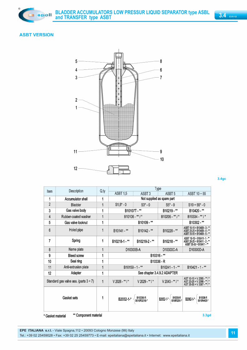
ASBT VERSION
3.4gc
3.3gd
BLADDER ACCUMULATORS LOW PRESSUR LIQUID SEPARATOR type ASBL and TRANSFER type ASBT

EPE ITALIANA s.r.l. - Viale Spagna,112 • 20093 Cologno Monzese (Mi) Italy Tel.: +39 02 25459028 • Fax: +39 02 25 25459773 • E-mail: [email protected] • Internet: www.epeitaliana.it
BLADDER ACCUMULATORS LOW PRESSUR LIQUID SEPARATOR type ASBL and TRANSFER type ASBT E 01-123.4
12
3.4.11 COMMISSIONING AND MAINTENANCEDelivery conditionsThe bladder accumulators’ type ASL and AST cannot be delivered withthe pre-charge. Depending on the size and quantity ordered, the bladder are shipped inboxes, in cartons, on pallets or wooden boxes on request. Unless otherwise required, certificates and documentation are providedtogether with the accumulators.
HandlingThe original packaging is suitable for handling and storage. Where necessary, you should use suitable lifting equipment to supportthe weight of the accumulators. However protect from impact the packaging and handle it with care.
StorageDuring storage in the warehouse, leave the product in its original packa-ging, keeping it away from heat sources and naked flames. The storagetemperature should be between +10 and +40°C. In addition to six months of storage, the precharge pressure must be totwo bar and make sure that inside there is lubrication fluid compatiblewith bladder polymer. After six years of storage, it is essential to proceed with the replacementof all elastomeric parts before the commissioning.
Marking on the nameplate of the accumulator With reference to the PED 97/23/EC classification, Article 3, Paragraph3 and / or risk categories I or II depending on the volume and maximumworking pressure, the accumulator indicates the following data:- Logo, name and country of the manufacturer - Mounth/year of production- Product code - Serial number - Maximum PS pressure and PT test pressure in bar - Min. and max. TS working temperature in Celsius - Volume V in litres - Group of fluids allowed (II) - CE marking (for volumes exceding 1 litre) with the identification number
of the notified body
It is strictly forbidden to: - weld, rivet or screw any item of the accumulator - engrave or permanently stamp the surfaces of the accumulator shell
and / or carry out other operations that could affect or change the me-chanical properties of the accumulator
- use the accumulator as a structural element: it should not be subjectedto stresses or loads
- change the data of the nameplate and / or accumulator without thepermission of the manufacturer
- use a (dangerous) fluid of Group 1 with equipment designed and ma-nufactured for fluids of Group 2.
InstallationBefore installation, you must perform a visual check to verify that the ac-cumulator has not suffered any damage during shipping / handling. Verify that the requested type matches with what stamped on the name-plate. We recommend using the accumulator with a suitable lock-off andsecurity block type BS (see Chap. 9). This device provides the user pro-
tection and equipment against damage caused by pressure peaks andalso males easy and safe the maintenance of the accumulator, simpli-fying the interception and discharging. The accumulators type AS maybe installed in any position from horizontal to vertical (preferably with thegas valve at the top), and the nameplate must be visible. Proceed to theassembly so that no abnormal force affects the pipes connected directlyor indirectly to the accumulator, so we recommend the use of supportingcomponents and also fastening (please see Chapter 7) to avoid the tran-smission of vibrations. If there are not used EPE safety blocks, makesure that the accumulator is connected to the hydraulic circuit by suitableconnection devices. Make sure the fluid is compatible with the elastomerof the bladder. Check that the max. allowed accumulator pressure isequal to or greater than that of the hydraulic circuit and that the tempe-rature during operation is maintained within the range expected. Makesure the fluid does not contain contaminants and/or abrasive.
Pre-charge of nitrogen (type AST)The pre-charge of gas should be performed after the connection to theadditional cylinders and after the installation of the accumulator in thehydraulic circuit. For the pre-charge, use only industrial dry nitrogen witha purity of min. 99%. It is important to use the nitrogen from a bottle equip-ped with a pressure reducing valve (see Chap.11.3). Use the EPE pre-charge and charging set type PC to check the charging pressure required,and adjust if necessary. If the pre-charge pressure is lower than required,connect the charging hose on one side and the other side connect it to thenitrogen bottle or to the pressure reducer. Slowly fill the nitrogen in the ac-cumulator until reaching a pressure slightly higher than that set value (+10 ÷ 15%). Close the bottle and remove the charging hose from the pre-loading set; wait until the gas temperature has stabilized (2 hours) andcalibrate the pressure, discharging the excess gas.Make sure that the pre-charge valve, fittings, pipes and anything elseare not subject to losses, by using, if necessary, soap and water. Tighten the protective caps manually.
Hydraulic pressurization- Check that the pre-charge pressure is adequate for the application - Ensure that the hydraulic pressure never exceeds the max pressure
allowed (PS) shown on the accumulator shell. To avoid this risk, use a safety device (see Chap. 9).
Maintenance- Periodically check the pre-charge pressure of the gas: after the com-
missioning, check after 2-3 weeks of operation and if there were noleaks, repeat the operation after 3 months; if the pressure at the sametemperature was stable, repeat the test yearly. For heavy-duty appli-cations, check the pre-charge every 6 months.
- Periodically (yearly) carry out a visual inspection of the accumulatorin order to detect any early signs of deterioration such as corrosion,deformation, etc.
- Comply with the requirements of the regulations concerning the veri-fication of the functionality of the equipment according to the countryof installation of the accumulator.
RepairIf for failure, scheduled check or retest it is necessary to remove the ac-cumulator from the system, prior to removal, isolate the accumulator fromthe installation and discharge pressure of the liquid. All bladder EPE ac-cumulators of the ASL and AST series may e repaired.

BLADDER ACCUMULATORS LOW PRESSUR LIQUID SEPARATOR type ASBL and TRANSFER type ASBT E 01-123.4
EPE ITALIANA s.r.l. - Viale Spagna,112 • 20093 Cologno Monzese (Mi) Italy Tel.: +39 02 25459028 • Fax: +39 02 25 25459773 • E-mail: [email protected] • Internet: www.epeitaliana.it
13
It may consist in replacing the bladder, the seals, the pre-charge valve(AST) and/or the parts of the gas and fluid valve. For reasons of functionality and security, it is recommended to use onlyoriginal spare parts.
Disassembly- Fasten the accumulator firmly in a vice or on a bench in a horizontal
position, taking care not to damage the outer surface.
3.4h- Remove gas valve, fastening the nut on the gas valve and remove the
nameplate
3.4i- Unscrew the vent screw
3.4l- Using a suitable wrench, unscrew the fluid valve (anti-extrusion plate)
3.4m- Remove the anti-extrusion plate
3.4n- Fold bladder somewhat and withdraw by turning it slightly
Refitting
- Cleaning and testing : clean all metallic parts on accumulator using anorganic reducer – visual inspection of valves– Clean bladder, i.e. usingisopropanol. Visual inspection of bladder for faults – inner inspectionof container for signs of corrosion. In event of coated containers, checkthe condition of the coating. Replace the parts deemed to be bad: theo-rings must always be replaced (see spare parts Section 3.4.10).
Tightening torques in Nm
0.7-1.5 l 3 - 5 l 10-55 l
Fluid port anti-extrusion plate 50 + 5 60 + 60 100 +10
Bleed screw 10 +2 10 +2 10 +2
Gas valve locknut 80 +20 100 +20 150 +30
Filling valve (AST) - - 30 +5

EPE ITALIANA s.r.l. - Viale Spagna,112 • 20093 Cologno Monzese (Mi) Italy Tel.: +39 02 25459028 • Fax: +39 02 25 25459773 • E-mail: [email protected] • Internet: www.epeitaliana.it
BLADDER ACCUMULATORS LOW PRESSUR LIQUID SEPARATOR type ASBL and TRANSFER type ASBT E 01-123.4
14
3.4r- Bleed screw with sealing ring- Mount the bleed screw with its sealing ring
3.4s- Tighten the hexagon nut SW1 on the gas valve- Mount the filling valve (ASBT)
Pre-charge (ASBT) after having fitted the accumulator on the system andhaving connected it to the additional cylinders.- Screw the pre-charge PC equipment on the gas valve. - Connect the equipment to the cylinder of nitrogen or to the pressure
reducer with the inflation tube. - Slowly enter the nitrogen in the accumulator until reaching a pressure
slightly higher than the set value (+ 10 ÷ 15%). - Close the cylinder and remove the connecting pipe from the equipment. - Wait until the gas temperature has stabilized (2 hours). - Calibrate the pressure discharging the excess gas.
Make sure that the gas valve, the fittings and the pipes are not subjectto losses and, if necessary, use soap and water. Tighten the protective caps manually. Demolition and recycling of the accumulatorBefore accumulator demolition or recycling, you should always dischargecompletely the pre-charge pressure and remove the gas valve (ASBT). If youneed, proceed decontaminating in relation to the fluid used prior to demolition.
3.4o- Drain air from bladder by pressing together
3.4p- Carefully moisten the inside of the bladder and the container with used
medium (roll container)
3.4q- Install the anti extrusion plate.

E 01-123.4
EPE ITALIANA s.r.l. - Viale Spagna,112 • 20093 Cologno Monzese (Mi) Italy Tel.: +39 02 25459028 • Fax: +39 02 25 25459773 • E-mail: [email protected] • Internet: www.epeitaliana.it
15
BLADDER ACCUMULATORS LOW PRESSUR LIQUID SEPARATOR type ASBL and TRANSFER type ASBT
3.4.12.2 LIFTING HOOKTo be used for the safe lifting of mounted accumulators:For accumulators 0,7÷5 lt (M22x1,5) code B2507/2For accumulators 10÷55 lt (M50x1,5) code B2507/5For accumulators V4 (7/8” UNF) code B2507/7
Dimension
3.4ab
3.4.12.3 CORE TOOLThe core tool is used to remove and reinstall the valve core type V4.Code B2508
Dimension
3.4ac
3.4.12 REPAIR TOOLS
3.4.12.1 BLADDER PULL RODThe pull rod screwed to the gas valve of the bladder for easy assemblyinto shell during reassembly. Pull rod is complete with fitting for EPE gasvalve and 3 extension segments to accommodate all size of accumula-tors.Code for complete kit: B2505-G2 / B2505-G6
Dimension
3.4aa
Reproduction is forbidden.In the spirit of continuous improvement, our products may be changed.


