User Guide - Etisalat€¦ · User Guide - Etisalat ... Maps ..... 147

Aspen B-JAC® 12.1
User�s Guide

Version Number: 12.1
June 2003
Copyright © 1981-2003 by Aspen Technology, Inc. All rights reserved.
AspenTech®, Aspen Engineering Suite�, Aspen Plus®, Aspen Properties�, Aspen B-JAC®, Aspen Hetran�, Aspen Teams�, Aspen Aerotran�, Aspen Custom Modeler®, Aspen ADSIM�, Aspen Chromatography®, Aspen Dynamics®, Aspen Water�, Aspen Utilities�, Aspen Rxfinery�, Aspen FCC®, Aspen Hydrocracker®, Aspen Hydrotreater�, Aspen CatRef®, Aspen Pinch®, Aspen Split�, Aspen Zyqad�, Aspen OnLine®, Aspen WebModels®, Batch Plus®, Polymers Plus®, Aspen OLI�, Aspen PEP Process Library�, Aspen MIMI�, InfoPlus.21®, the aspen leaf logo, and Plantelligence are trademarks or registered trademarks of Aspen Technology, Inc., Cambridge, MA.
FLEXlm� is a trademark of GLOBEtrotter Software, Inc., a Macrovision company.
All other brand and product names are trademarks or registered trademarks of their respective companies.
This document is intended as a guide to using AspenTech's software. This documentation contains AspenTech proprietary and confidential information and may not be disclosed, used, or copied without the prior consent of AspenTech or as set forth in the applicable license agreement. Users are solely responsible for the proper use of the software and the application of the results obtained.
Although AspenTech has tested the software and reviewed the documentation, the sole warranty for the software may be found in the applicable license agreement between AspenTech and the user. ASPENTECH MAKES NO WARRANTY OR REPRESENTATION, EITHER EXPRESSED OR IMPLIED, WITH RESPECT TO THIS DOCUMENTATION, ITS QUALITY, PERFORMANCE, MERCHANTABILITY, OR FITNESS FOR A PARTICULAR PURPOSE.
Corporate
Aspen Technology, Inc. Ten Canal Park Cambridge, MA 02141-2201 USA Phone: (1) (617) 949-1000 Fax: (1) (617) 949-1030 URL: http://www.aspentech.com

Aspen B-JAC 12.1 User Guide Contents • iii
Contents
Aspen B-JAC Overview 1-1 Aspen B-JAC Programs ...................................................................................................1-1 Aspen Plus Integration .....................................................................................................1-2 Aspen Pinch Integration ...................................................................................................1-2 Aspen Zyqad Integration..................................................................................................1-3 License & Service Agreements ........................................................................................1-3 Technical Support ............................................................................................................1-4
Contacting Customer Support ..............................................................................1-4 Hours ....................................................................................................................1-5 Phone....................................................................................................................1-5 Fax........................................................................................................................1-6 E-mail ...................................................................................................................1-6
Aspen B-JAC User Interface 2-1 Version Control Utility (BJACVC.exe) ...........................................................................2-1 User Customized Database Files......................................................................................2-1 Accessing Aspen B-JAC Program Files...........................................................................2-2 Filenames & Filetypes......................................................................................................2-3 Importing/Exporting Design Data....................................................................................2-4 General Operating Procedures .........................................................................................2-4 The Aspen B-JAC Window..............................................................................................2-6
Title Bar................................................................................................................2-6 Navigation Tree, Forms and Sheets .....................................................................2-6 Prompt Area and Status Bar .................................................................................2-6 Key Functions ......................................................................................................2-7 Mouse Functions ..................................................................................................2-7 Menu Bar..............................................................................................................2-8 Toolbars..............................................................................................................2-10
Data Maintenance...........................................................................................................2-11 Units of Measure ................................................................................................2-11 Heat Exchanger Standards .................................................................................2-12 Chemical Databank (B-JAC Props & Priprops).................................................2-12 Materials Databank (B-JAC Databank & Primetals) .........................................2-12 Materials Defaults (Defmats) .............................................................................2-12 Costing (Newcost Database) ..............................................................................2-12

iv • Contents Aspen B-JAC 12.1 User Guide
Frequently Used Materials and Chemical Components.....................................2-12 Program Settings ............................................................................................................2-12 Program Input.................................................................................................................2-13
Input Fields.........................................................................................................2-13 Units of Measure - Field Specific ......................................................................2-15 Databank Reference ...........................................................................................2-15 Range Checks.....................................................................................................2-16 Change Codes.....................................................................................................2-16 The Database Concept........................................................................................2-17
Program Output ..............................................................................................................2-17 Help Facility...................................................................................................................2-18
Getting Help .......................................................................................................2-18
Aspen Hetran 3-1 Hetran Input......................................................................................................................3-1
Problem Definition...............................................................................................3-1 Physical Property Data .........................................................................................3-9 Exchanger Geometry..........................................................................................3-26 Design Data ........................................................................................................3-54 Program Options ................................................................................................3-62
Hetran Results ................................................................................................................3-71 Design Summary ................................................................................................3-71 Thermal Summary..............................................................................................3-76 Mechanical Summary.........................................................................................3-82 Calculation Details .............................................................................................3-87
Hetran Design Methods..................................................................................................3-90 Optimization.......................................................................................................3-90 No Phase Change ...............................................................................................3-94 Simple Condensation..........................................................................................3-95 Complex Condensation ......................................................................................3-96 Simple Vaporization...........................................................................................3-98 Complex Vaporization .....................................................................................3-100
Aspen Teams 4-1 Teams Input......................................................................................................................4-1
Problem Definition...............................................................................................4-1 Exchanger Geometry............................................................................................4-3 Materials.............................................................................................................4-52 Program Options ................................................................................................4-53
Teams Results ................................................................................................................4-63 Input Summary...................................................................................................4-63 Design Summary ................................................................................................4-64 Vessel Dimensions .............................................................................................4-68 Price....................................................................................................................4-72 Drawings ............................................................................................................4-72 Code Calculations ..............................................................................................4-73

Aspen B-JAC 12.1 User Guide Contents • v
Aspen Aerotran 5-1 Aerotran Input ..................................................................................................................5-1
Problem Definition...............................................................................................5-1 Physical Property Data .........................................................................................5-8 Exchanger Geometry..........................................................................................5-19 Design Data ........................................................................................................5-27 Program Options ................................................................................................5-32
Aerotran Results.............................................................................................................5-38 Design Summary ................................................................................................5-38 Thermal Summary..............................................................................................5-42 Mechanical Summary.........................................................................................5-46 Calculation Details .............................................................................................5-48
Aerotran Design Methods ..............................................................................................5-50 Optimization Logic ............................................................................................5-50 Optimization of Heat Transfer Area...................................................................5-50 Heat Transfer Coefficients .................................................................................5-51 Pressure Drop, Outside Tubes............................................................................5-51 Pressure Drop, Inside Tubes...............................................................................5-51 Pricing ................................................................................................................5-51 MTD Calculation................................................................................................5-51 Maximum Velocities ..........................................................................................5-52 Fans ....................................................................................................................5-52 Nozzles Design Methods....................................................................................5-52 Heat Transfer Area .............................................................................................5-52 Tube Pass Configuration ....................................................................................5-52 No Phase Change ...............................................................................................5-52 Simple Condensation..........................................................................................5-53 Complex Condensation ......................................................................................5-53 Simple Vaporization...........................................................................................5-55
Ensea 6-1 Problem Definition...........................................................................................................6-1
Headings Sheet.....................................................................................................6-1 Ensea Application Options Sheet.........................................................................6-1 Application Type..................................................................................................6-1 Drawing................................................................................................................6-2
Exchanger Geometry........................................................................................................6-2 Exchanger.............................................................................................................6-2 Tubes & Baffles ...................................................................................................6-4 Tube Layout .........................................................................................................6-6 Tube Row Details...............................................................................................6-10
Ensea Results..................................................................................................................6-10 Input Data...........................................................................................................6-11 Warnings & Messages........................................................................................6-11 Summary ............................................................................................................6-11 Tube Row Details...............................................................................................6-12
vi • Contents Aspen B-JAC 12.1 User Guide
Tube Layout Drawing ........................................................................................6-12 Logic...............................................................................................................................6-12
Ensea Logic ........................................................................................................6-12 References ......................................................................................................................6-14
Ensea References................................................................................................6-14
Qchex 7-1 Qchex Input ......................................................................................................................7-1
Problem Definition...............................................................................................7-1 Exchanger Geometry............................................................................................7-1 Exchanger Data ....................................................................................................7-4 Design Data ........................................................................................................7-11
Qchex Results.................................................................................................................7-12 Qchex Logic ...................................................................................................................7-13
Mechanical Design.............................................................................................7-13 Design Pressure ..................................................................................................7-13 Design Temperature and Allowable Stresses.....................................................7-13 Corrosion Allowance..........................................................................................7-13 Cylinders and Covers .........................................................................................7-13 Tubesheets..........................................................................................................7-14 Flanges ...............................................................................................................7-14 Tubes ..................................................................................................................7-14 Nozzles and Nozzle Flanges ..............................................................................7-14
Material Prices................................................................................................................7-14 Material Prices....................................................................................................7-14 Labor Hours........................................................................................................7-15 Budget Price .......................................................................................................7-15 Quantity of Materials .........................................................................................7-16 Non-standard Construction ................................................................................7-16 Extreme Design Conditions ...............................................................................7-16 Premium Materials .............................................................................................7-16 Non-competitive or Rush Orders .......................................................................7-16 Regional Differences..........................................................................................7-16
Qchex References...........................................................................................................7-16
Props 8-1 Application Options .........................................................................................................8-1
Props Application Options Sheet .........................................................................8-1 Property Options ..............................................................................................................8-2
Condensation Options Sheet ................................................................................8-2 Condensation/ Vaporization Curve Calculation Method .....................................8-3 Condensation Curve Calculation Type ................................................................8-4 Vaporization Options Sheet .................................................................................8-5
Compositions....................................................................................................................8-5 Composition Sheet ...............................................................................................8-5 Component Properties ..........................................................................................8-6

Aspen B-JAC 12.1 User Guide Contents • vii
Interaction Parameters Sheet ................................................................................8-8 NRTL - Alpha parameters..................................................................................8-10 Uniquac - Surface & Volume parameters ..........................................................8-10
Results ............................................................................................................................8-10 Properties Over a Range of Temperatures .........................................................8-10 VLE ....................................................................................................................8-10
Props Logic ....................................................................................................................8-10 Databank Structure.............................................................................................8-10 Temperature Ranges...........................................................................................8-10 Effect of Pressure ...............................................................................................8-11 Mixtures .............................................................................................................8-11
Metals 9-1 Input .................................................................................................................................9-1
General Sheet .......................................................................................................9-1 Results ..............................................................................................................................9-2
Metals Results ......................................................................................................9-2 Warnings & Messages..........................................................................................9-2 Properties Independent of Temperature ...............................................................9-2 Properties Dependent on Temperature.................................................................9-2 Gasket Properties..................................................................................................9-2
Metals Directory - ASTM - Generic ................................................................................9-3 References ........................................................................................................................9-4
Metals References ................................................................................................9-4
Priprops 10-1 Introduction ....................................................................................................................10-1 Accessing the Priprops databank....................................................................................10-1 Property Reference.........................................................................................................10-2 Property Estimation........................................................................................................10-3
Primetals 11-1 Introduction ....................................................................................................................11-1
Currency .............................................................................................................11-2 Material Type .....................................................................................................11-3 Material Class.....................................................................................................11-3 External Pressure Chart Reference.....................................................................11-3
Example Input to Primetals ............................................................................................11-4 Example Input to Primetals ................................................................................11-4 Steps to create a private material........................................................................11-4
Newcost Database 12-1 Introduction ....................................................................................................................12-1 Labor & Cost Standards .................................................................................................12-2
General Cost and Labor Adjustment..................................................................12-2

viii • Contents Aspen B-JAC 12.1 User Guide
Fabrication and Operation Standards .................................................................12-2 Material Dependent Fabrication Standards ........................................................12-2 Welding Standards .............................................................................................12-2 Labor Efficiency Factors....................................................................................12-2 Material Prices....................................................................................................12-2 Part numbers for bill of materials and drawings ................................................12-3 Horizontal support standard dimensions ............................................................12-3
Newcost Database Example ...........................................................................................12-3
Aspen B-JAC Example 13-1 Aspen B-JAC Example: The User Interface ..................................................................13-2 Aspen B-JAC Example: General Specifications............................................................13-4 Aspen B-JAC Example: Specifying Components..........................................................13-7 Aspen B-JAC Example: Completing Property Specifications.......................................13-9 Aspen B-JAC Example: Specifying Geometry............................................................13-11 Aspen B-JAC Example: Specifying Design Data ........................................................13-13 Aspen B-JAC Example: Running the Problem............................................................13-15 Aspen B-JAC Example: Viewing Results....................................................................13-17 Aspen B-JAC Example: Tuning the Design ................................................................13-23 Aspen B-JAC Example: Performing Mechanical Design ............................................13-25 Aspen B-JAC Example: Specifying Geometry in Teams ............................................13-27 Aspen B-JAC Example: Specifying Materials for Teams ...........................................13-34 Aspen B-JAC Example: Running Teams.....................................................................13-36 Aspen B-JAC Example: Viewing Teams Results ........................................................13-38 Aspen B-JAC Example: Addressing Problems Discovered by Teams ........................13-42
Exporting Results from B-JAC to Excel 14-1 Introduction ....................................................................................................................14-1 Export Features ..............................................................................................................14-1
B-JAC Templates ...............................................................................................14-1 Exporting results to a B-JAC standard summary template or your customized template ..............................................................................................................14-2 Spread sheet created with Excel open ................................................................14-2 Creating your own customized Template...........................................................14-2
Copying Data from a B-JAC Application to Excel........................................................14-3 Copy Format:......................................................................................................14-3 Copying Individual fields:..................................................................................14-3 Copying Columns of information: .....................................................................14-3 Copying Tables of information: .........................................................................14-3 Copying drawings: .............................................................................................14-3 Example of Pasting Aspen B-JAC results into Excel. .......................................14-3
Launching B-JAC Programs from Excel .......................................................................14-5
Using the Aspen B-JAC ActiveX Automation Server 15-1 Introduction ....................................................................................................................15-1 About the Automation Server ........................................................................................15-2

Aspen B-JAC 12.1 User Guide Contents • ix
Using the Automation Server.........................................................................................15-2 Releasing Objects...............................................................................................15-3 Error Handling....................................................................................................15-4
Viewing the Aspen B-JAC Objects................................................................................15-4 Overview of the Aspen B-JAC Objects .........................................................................15-5
Object Model Diagram.......................................................................................15-5 The BJACApp Object ........................................................................................15-5 Example of Opening an Existing File ................................................................15-6 The ATVApp object...........................................................................................15-6 Example of using an ATVApp object ................................................................15-7 ATVScalar Object and ATVArray Object .........................................................15-8 Example of accessing data objects .....................................................................15-8
Programming with Aspen B-JAC Objects ...................................................................15-10 Creating Application and File Operations........................................................15-10 Enumerating Objects ........................................................................................15-13 Checking Status................................................................................................15-13 Controlling the Units of Measure.....................................................................15-15 Accessing Data.................................................................................................15-16 Exploring Variables..........................................................................................15-17 Limitations and Restrictions.............................................................................15-18
Reference Information..................................................................................................15-19 Members of Class BJACApp ...........................................................................15-19 Members of Class ATVApp.............................................................................15-20 Members of Class ATVScalar..........................................................................15-21 Members of Class ATVArray ..........................................................................15-21 Member Descriptions .......................................................................................15-22 Error Descriptions ............................................................................................15-39
Appendix A-1 Tubing .............................................................................................................................A-1
Tube Wall Thickness...........................................................................................A-1 Tube Low Fin Information..................................................................................A-2 Enhanced Surfaces Standard Sizes......................................................................A-2
Material Selection ...........................................................................................................A-4 Generic Materials ................................................................................................A-4 Gaskets - hot side ................................................................................................A-5 Gaskets - cold side...............................................................................................A-5 Corrosion Table...................................................................................................A-5
Baffle Cuts.....................................................................................................................A-10 Asme Code Cases..........................................................................................................A-11
ASME Code Case 2278.....................................................................................A-11 ASME Code Case 2290.....................................................................................A-11
Pipe Properties...............................................................................................................A-12 ANSI Pipe Dimensions .....................................................................................A-12 DIN / ISO 4200 Pipe Dimensions .....................................................................A-14 Standard Nozzle Flange Ratings .......................................................................A-14

x • Contents Aspen B-JAC 12.1 User Guide
Technical References ....................................................................................................A-14 Introduction .......................................................................................................A-14 General ..............................................................................................................A-15 Shell Side Heat Transfer and Pressure Drop.....................................................A-18 Tube Side Heat Transfer and Pressure Drop.....................................................A-23 Vibration Analysis.............................................................................................A-25 Fans ...................................................................................................................A-26
Index I-1

Aspen B-JAC 12.1 User Guide Aspen B-JAC Overview • 1-1
C H A P T E R 1
Aspen B-JAC Overview
Aspen B-JAC Programs The Aspen B-JAC software includes a number of programs for the thermal design, mechanical design, cost estimation, and drawings for heat exchangers and pressure vessels.
The major design programs are: Aspen Hetran�
Thermal Design of Shell & Tube Heat Exchangers
Aspen Teams�
Mechanical Design, Cost Estimation, and Design Drawings of Shell &Tube Heat Exchangers and Pressure Vessels
Aspen Aerotran�
Thermal Design of Air Cooled Heat Exchangers, Flue Gas Heat Recuperators, and Fired Heater Convection Sections
In addition to the major design programs, these programs support the design programs: Props Chemical Physical Properties Databank Priprops Program to Build a Private Databank for Props Metals Metal Properties Databank Primetals Program to Build a Private Databank for Metals Ensea Tubesheet Layout Program Qchex Budget Cost Estimation Program Draw Graphics Interface Program for Drawings Newcost Program for Maintaining Labor & Material Databases Defmats Program for Establishing Default Materials

1-2 • Aspen B-JAC Overview Aspen B-JAC 12.1 User Guide
Aspen Plus Integration The Aspen B-JAC Hetran and Aerotran programs are completely integrated with the Aspen Plus process simulation software. Users with licenses for both the Aspen B-JAC thermal analysis software and the Aspen Plus simulation software can use the Aspen B-JAC thermal models for shell and tube heat exchangers and air-cooled heat exchangers within the Aspen Plus flowsheet.
The models can be accessed from Aspen Plus by selecting the blocks Hetran or Aerotran for the heat transfer unit operations. Stream and property curve data for these blocks can be supplied to the Aspen B-JAC programs by Aspen Plus or from within the Aspen B-JAC input file, which is referenced in the Aspen Plus input for the block. All exchanger geometry data must be specified through the Aspen B-JAC input file.
During simulation the Aspen Plus simulator repetitively calls the Aspen B-JAC analysis programs to predict the outlet conditions of the heat transfer equipment. The results of the analysis are returned to Aspen Plus which then feeds them to subsequent blocks. A subset of the exchanger performance can be viewed from within the Aspen Plus environment. All results of the block can be viewed in detail through the Aspen B-JAC user interface.
Aspen Pinch Integration The Aspen B-JAC Hetran program is completely integrated with the Aspen Pinch process synthesis software. Users with licenses for both the Aspen B-JAC thermal analysis software and the Aspen Pinch software can use the Aspen B-JAC thermal models for shell and tube heat exchangers within the Aspen Pinch flowsheet.
The models can be accessed from Aspen Plus by selecting the block Hetran for the heat transfer unit operations. Stream and property curve data for these blocks can be supplied to the Aspen B-JAC programs by Aspen Pinch or from within the Aspen B-JAC input file which is referenced in the Aspen Pinch input for the block. All exchanger geometry data must be specified through the Aspen B-JAC input file.
During simulation the Aspen Pinch simulator repetitively calls the Aspen B-JAC analysis programs to predict the outlet conditions of the heat transfer equipment. The results of the analysis are returned to Aspen Pinch which then feeds them to subsequent blocks. A subset of the exchanger performance can be viewed from within the Aspen Pinch environment. All results of the block can be viewed in detail through the Aspen B-JAC user interface.

Aspen B-JAC 12.1 User Guide Aspen B-JAC Overview • 1-3
Aspen Zyqad Integration The Aspen B-JAC Hetran program is completely integrated with Aspen Zyqad. Aspen Zyqad is an engineering database tool used to capture process knowledge about the design, construction, or operation of a process plant. The database contains a number of data models to store information about the process streams, the process configuration, and the individual pieces of process equipment. The user can retrieve the information and generate specialized reports and equipment specification sheets from the data in the database.
License & Service Agreements The use of the Aspen B-JAC software is governed by a "License Agreement" for licensed clients. These are legally binding contracts which have been signed and executed by your company and Aspen Technology, Inc.. Some of the points included in these contracts are shown below.
Access Access to the programs is limited to the employees of the Customer in support of the Customer's business. Specifically excluded is access by persons other than the Customer's employees or use by the Customer's employees for any purpose outside the Customer's business.
License The license authorizes the Customer to use the licensed program on the designated computers. Backup copies can be made.
The license is limited to the Customer, and may not be transferred or assigned, nor may it be extended to any subsidiaries or joint ventures except as agreed in writing between the Customer and Aspen Technology, Inc.
The licensed programs are the sole and exclusive property of Aspen Technology, Inc. The licensed Customer does not become the owner of the programs, but has the right to use the programs in accordance with the license agreement.
Warranty and Limitation of Liability The licensed programs are offered as is, and it is the Customer's responsibility to determine if the programs are adequate for the Customer's requirements. The Customer understands that the programs are of such complexity that they may have inherent

1-4 • Aspen B-JAC Overview Aspen B-JAC 12.1 User Guide
defects and that Aspen Technology, Inc. makes no warranty that all such defects will be corrected. Aspen Technology, Inc. will make a reasonable effort to correct or bypass properly reported and documented programming errors in regularly scheduled program updates.
In no event shall Aspen Technology, Inc., its agents, suppliers, or contractors be liable to the Customer or any third party for consequential damages arising from use of the Aspen B-JAC programs. It is the Customer's responsibility to check the results of all computer programs.
Technical Support AspenTech customers with a valid license and software maintenance agreement can register to access the Online Technical Support Center at:
http://support.aspentech.com This web support site allows you to: • Access current product documentation • Search for tech tips, solutions and frequently asked questions
(FAQs) • Search for and download application examples • Search for and download service packs and product updates • Submit and track technical issues • Search for and review known limitations • Send suggestions
Registered users can also subscribe to our Technical Support e-Bulletins. These e-Bulletins are used to proactively alert users to important technical support information such as: • Technical advisories • Product updates • Service Pack announcements • Product release announcements
Customer support is also available by phone, fax, and email for customers with a current support contract for this product. For the most up-to-date phone listings, please see the Online Technical Support Center at http://support.aspentech.com.
Contacting Customer Support
Aspen B-JAC 12.1 User Guide Aspen B-JAC Overview • 1-5
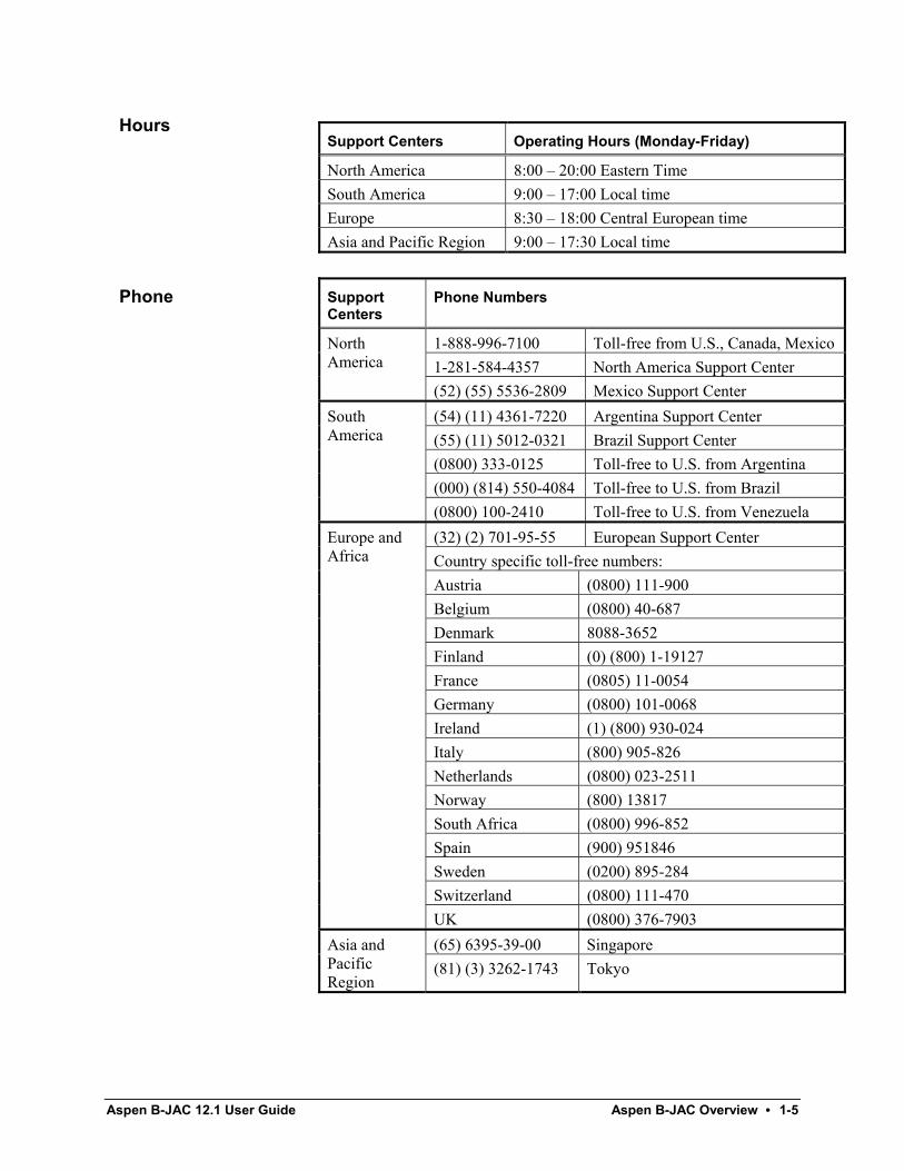
Support Centers Operating Hours (Monday-Friday)
North America 8:00 � 20:00 Eastern Time South America 9:00 � 17:00 Local time Europe 8:30 � 18:00 Central European time Asia and Pacific Region 9:00 � 17:30 Local time
Support Centers
Phone Numbers
1-888-996-7100 Toll-free from U.S., Canada, Mexico 1-281-584-4357 North America Support Center
North America
(52) (55) 5536-2809 Mexico Support Center (54) (11) 4361-7220 Argentina Support Center (55) (11) 5012-0321 Brazil Support Center (0800) 333-0125 Toll-free to U.S. from Argentina (000) (814) 550-4084 Toll-free to U.S. from Brazil
South America
(0800) 100-2410 Toll-free to U.S. from Venezuela (32) (2) 701-95-55 European Support Center Country specific toll-free numbers: Austria (0800) 111-900 Belgium (0800) 40-687 Denmark 8088-3652 Finland (0) (800) 1-19127 France (0805) 11-0054 Germany (0800) 101-0068 Ireland (1) (800) 930-024 Italy (800) 905-826 Netherlands (0800) 023-2511 Norway (800) 13817 South Africa (0800) 996-852 Spain (900) 951846 Sweden (0200) 895-284 Switzerland (0800) 111-470
Europe and Africa
UK (0800) 376-7903 (65) 6395-39-00 Singapore Asia and
Pacific Region
(81) (3) 3262-1743 Tokyo
Hours
Phone

1-6 • Aspen B-JAC Overview Aspen B-JAC 12.1 User Guide
Support Centers
Fax Numbers
North America
1-281-504-3999
South America
(54) (11) 4361-7220 (Argentina) (55) (11) 5012-4442 (Brazil)
Europe (32) (2) 701-94-45 Asia and Pacific Region
(65) 6395-39-50 (Singapore) (81) (3) 3262-1744 (Tokyo)
Support Centers E-mail
North America [email protected] (Engineering Suite) [email protected] (Hyprotech products) [email protected] (Aspen ICARUS products) [email protected] (Aspen MIMI products) [email protected] (Aspen PIMS products) [email protected] (Aspen Retail products) [email protected] (Advanced Control products) [email protected] (Manufacturing Suite) [email protected] (Mexico)
South America [email protected] [email protected] (Argentina)
Europe [email protected] (Engineering Suite) [email protected] (Hyprotech products) [email protected] (CIMVIEW products) [email protected] (Metals products) [email protected] (All other suites)
Asia and Pacific Region
[email protected] (Singapore: Engineering Suite) [email protected] (Hyprotech products) [email protected] (Singapore: Aspen MIMI) [email protected] (Singapore: Aspen Retail) [email protected] (Singapore: All other suites) [email protected] (Tokyo: Engineering Suite) [email protected] (Tokyo: All other suites)
Fax

Aspen B-JAC 12.1 User Guide Aspen B-JAC User Interface • 2-1
C H A P T E R 2
Aspen B-JAC User Interface
Version Control Utility (BJACVC.exe) Aspen B-JAC provides a version control utility, BJACVC, which enables you to switch between versions of B-JAC. BJACVC.exe is located in the XEQ folder of the installed B-JAC program.
To run the BJACVC.exe utility, locate the file using Explorer, and then double click the file.
Selecting a B-JAC program version: Select which version you wish to run and the utility will update the MS Windows registry to allow you to run the selected B-JAC program version. BJACVC automatically executes when you open a B-JAC program version that is not registered properly.
Copying customized files: Select the source version where your existing customized database files are located. Next, select the target new version where you wish to copy the database files. Next, select the files you wish to transfer. Then select Copy to copy the customized files to the new version.
Copying program settings: To copy the program settings from an existing B-JAC version to a new version, select the source version. Next, select the target new program version. Then select Apply to copy the program settings to the new targeted version.
User Customized Database Files There are a number of database files that you can change to customize the operation of the Aspen B-JAC programs, as well as alter the program answers. These customized database files are located in a default program folder or in a user specified directory. If you elect to use the default folder location, those database files
2-2 • Aspen B-JAC User Interface Aspen B-JAC 12.1 User Guide
must be copied from the previous B-JAC program default folder to the new Dat\PDA folder.
You can use the Version Control Utility, BJACVC, to copy your customized files from an existing version to the new B-JAC version.
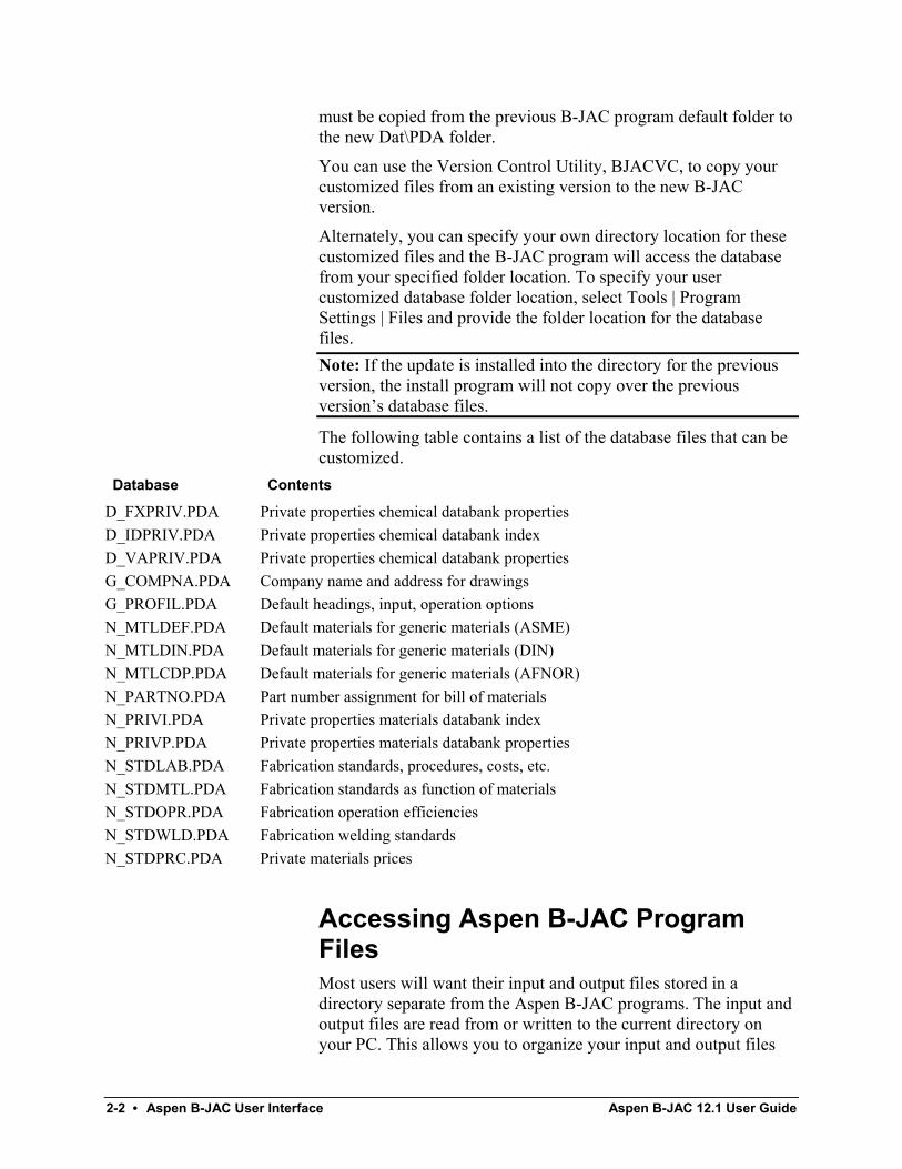
Alternately, you can specify your own directory location for these customized files and the B-JAC program will access the database from your specified folder location. To specify your user customized database folder location, select Tools | Program Settings | Files and provide the folder location for the database files. Note: If the update is installed into the directory for the previous version, the install program will not copy over the previous version�s database files.
The following table contains a list of the database files that can be customized.
Database Contents
D_FXPRIV.PDA Private properties chemical databank properties D_IDPRIV.PDA Private properties chemical databank index D_VAPRIV.PDA Private properties chemical databank properties G_COMPNA.PDA Company name and address for drawings G_PROFIL.PDA Default headings, input, operation options N_MTLDEF.PDA Default materials for generic materials (ASME) N_MTLDIN.PDA Default materials for generic materials (DIN) N_MTLCDP.PDA Default materials for generic materials (AFNOR) N_PARTNO.PDA Part number assignment for bill of materials N_PRIVI.PDA Private properties materials databank index N_PRIVP.PDA Private properties materials databank properties N_STDLAB.PDA Fabrication standards, procedures, costs, etc. N_STDMTL.PDA Fabrication standards as function of materials N_STDOPR.PDA Fabrication operation efficiencies N_STDWLD.PDA Fabrication welding standards N_STDPRC.PDA Private materials prices
Accessing Aspen B-JAC Program Files Most users will want their input and output files stored in a directory separate from the Aspen B-JAC programs. The input and output files are read from or written to the current directory on your PC. This allows you to organize your input and output files

Aspen B-JAC 12.1 User Guide Aspen B-JAC User Interface • 2-3
however you wish. We recommend that you run from a directory other than the directory in which the Aspen B-JAC programs are installed.
Filenames & Filetypes Although the Aspen B-JAC software works on several different computers and operating systems, there is a high degree of similarity in the use of filenames and filetypes for input and output files.
The filename and filetype form the name under which the file is stored on the storage medium (usually disk).
Filenames The filename can be up to 255 characters in length and may use the letters A-Z a-z, numbers 0-9, and special characters - _ & $.
Filetypes The filetype (filename extension) is automatically established by the Aspen B-JAC software as follows: Filetype Description BJT Aspen B-JAC Input/Output File (Release 10.0 and greater) BFD Aspen B-JAC Drawing File BDT Aspen B-JAC Template file (user can save an existing
*.BJT input file as a *.BDT template file, and then reuse the template to create other design input files, using the Windows Save As feature).
BJI Aspen B-JAC Input File (previous versions) BJO Aspen B-JAC Output File (previous versions) BJA Aspen B-JAC Archive File (Input/Output data previous
versions)
Whenever an Aspen B-JAC program requests a filename, it is expecting the name without the filetype. The program will append the filetype.
Alternate Filetypes Filetype Description TAF Aspen Hyprotech TASC Output file (for import into the
Aspen Teams program DBO HTRI Output file (for impurt into the Aspen Teams
program) OUT HTRI Output file (for impurt into the Aspen Teams
program)

2-4 • Aspen B-JAC User Interface Aspen B-JAC 12.1 User Guide
Importing/Exporting Design Data AutomationX The Aspen B-JAC input/results file may be exported to other OLE compliant systems for use with other programs via various automation utilities. An example automation file has been provided in the example sub-directory, XMP, of the installed B-JAC program.
Export Drawings Drawings may be exported to a *.DXF CAD format file or to an Autocad inventor file.
Results Aspen Hetran, Teams, and Aerotran results may be exported to a *.doc file format. Aspen Teams detailed results may also be exported to an *.rtf format file.
General Operating Procedures Most of the Aspen B-JAC programs follow these general operating procedures. 1 Start Aspen B-JAC.
On your desktop click the Aspen B-JAC shortcut icon or click Start | Programs | AspenTech | Aspen Engineering Suite | Aspen B-JAC 12.1 | Aspen B-JAC Design System.
2 Select the appropriate Aspen B-JAC program. On the Aspen B-JAC Design System dialog box, do one of the following: On the New tab, click the checkbox next to the B-JAC program you want to use and click OK. or Click the Existing tab and select the file you want to open and click OK.
3 Enter the required data. Use the Navigation Tree or click the Next button on the toolbar to display the required input forms and sheets, and enter the data.
4 Run the problem. On the toolbar click the Run button or on the menu bar click Run | Run Program.

Aspen B-JAC 12.1 User Guide Aspen B-JAC User Interface • 2-5
5 Review the Results. Use the Navigation Tree to display the results.
6 Save the input data at any time. On the toolbar click the Save button or on the menu bar click File | Save.
7 Print a hard copy of the results, if desired. On the toolbar click the Print button or on the menu bar click File | Print. In the dialog box, check the boxes next to the desired output, and click Print.
8 If appropriate, make changes to the input data and repeat steps 4 through 7 until you have the desired solution.
9 Update the file with current geometry. On the menu bar click Run | Update.
10 Transfer design information to other programs, if desired. On the menu bar click Run | Transfer. In the dialog box, check the box next to the desired program and click OK.
11 Exit Aspen B-JAC. On the menu bar click File | Exit. The program prompts you to save changes. Click the appropriate button.

2-6 • Aspen B-JAC User Interface Aspen B-JAC 12.1 User Guide
The Aspen B-JAC Window
The bar at the top of the window displays the current program and file name.
Use the Minimize and Maximize and Restore screen control button to change the size of the program window and return the window to the original settings. The Close button closes the active program or file.
Each Aspen B-JAC program has a Navigation Tree which appears in the left pane of the program window. The tree is organized by Input and Results folders that contain program-specific forms.
Expand the folders to display the forms. Use the scroll bar to scroll through the forms.
Each form contains one or more sheets for entering data in various input fields or for reviewing results. Tabs display the names of the different sheets. To display a sheet, click on the appropriate tab.
Title Bar
Navigation Tree, Forms and Sheets
Prompt Area and Status Bar

Aspen B-JAC 12.1 User Guide Aspen B-JAC User Interface • 2-7
This Prompt area in the Program window provides information to help you make choices or perform tasks. It contains a description about the current input field.
The Status bar at the bottom of the main Aspen B-JAC window displays information about the current program status and input field status. If value entered for an input field is outside the normal range, a warning will be display in the Status Bar with the recommend value limits. Key Description F1 Activates the Help system Arrow Keys Moves the location of the cursor within an
input field and scrolls through the options in a given list
Delete Key Deletes the character at the current cursor position and shifts the remainder of the input
Home Key Returns the cursor to the beginning of the input field
End Key Moves the cursor to the end of the input field Forward Tab Key Scrolls the user through the input fields of a
form Backward Tab Key Move cursor back to previous field Control + Delete Keys
Erases the characters from the cursor position to the end of the input field
Page Up/Page Down Keys
Scrolls the user through the forms of the Menu Tree
Backspace Key Deletes the character to the left of the current cursor position in an input field
In the following descriptions, "click" means to place the mouse pointer on the item and press the left mouse-button. Location Action Menu Bar Click the appropriate menu to display the choices;
then click the desired option Toolbar Click the desired toolbar button Forms Click the desired form in the Menu tree Sheets Click the desired tab at the top of the form to move
between the sheets. Input Fields Click the desired input field.
List items: click the arrow key to the right of the input field to display the items, then click the desired option on the list Checkbox: click the checkbox to toggle between selecting and clearing the checkbox.
Key Functions
Mouse Functions

2-8 • Aspen B-JAC User Interface Aspen B-JAC 12.1 User Guide
Location Action Scroll Page Up Click the up direction arrow Scroll Page Down
Click the down direction arrow
Help Click the input field that you need help, and then select the F1 key. For "What's This" help, click the "?" button on the toolbar. Then point to the input field that you need help on and click.
The program has a number of additional features that can be accessed through a menu bar at the top of each screen. Using the left mouse button, click on a menu name to see the pull down options available. Click on a desired option or press the "Alt" key and the underscored character shown (some options can be accessed by a given "Ctrl" key + letter combination). Option Description New (Ctrl+N) Opens new file for desired Aspen B-JAC program Open (Ctrl+O) Opens existing Aspen B-JAC program file Close Closes a chosen Aspen B-JAC program window Add Application Opens a chosen Aspen B-JAC program window Remove Application
Removes a chosen Aspen B-JAC program window
Save (Ctrl+S) Saves current file under chosen filename Save As Saves current file as a different filename Export To Export results to Excel, a DXF file, a RTF file, or a
DOC file Print Setup Allows for change to printing options Print (Ctrl+P) Prints desired results sections from Aspen B-JAC
program Description Displays the contents of the Description field in the
input file Exit Exits Aspen B-JAC program and return user to
Windows Option Description Undo Undoes the last edit operation. Cut (Ctrl+X) Deletes the highlighted text. Copy (Ctrl+C) Saves a copy of the highlighted text. Paste (Ctrl+V) Paste inserts text from a copy to directed location
Menu Bar
File Menu
Edit Menu

Aspen B-JAC 12.1 User Guide Aspen B-JAC User Interface • 2-9
Option Description Run "Program" Runs a chosen Aspen B-JAC program Stop Stops the run of a chosen Aspen B-JAC program Transfer Transfers design information into another BJAC
program Update Updates file with final design information Option Description Data Maintenance
Provides access to units of measure, chemical database reference, material database, and Costing database.
Program Settings
Default units setting and headings for drawings
Security Access to Aspen B-JAC security program. Language Sets language to English, French, German, Spanish,
Italian (Chinese and Japanese to be offered in a later version).
Plot Plots results functions. Add Curve Allows the addition of another curve to an existing
plotted curve Option Description Tool Bar Shows or hides the Tool Bar Status Bar Shows or hides the Status Bar Zoom In Enlarges sections of the Aspen B-JAC drawings Zoom Out Returns drawings to normal size Refresh Refreshes screen Variable List Displays variable list for form. Name Description Cascade Arranges program windows one behind the other Tile Horizontal Arranges program windows one on top another Tile Vertical Arranges program windows one besides the other Arrange Icons Automatically arranges icons Create Creates a window for a Aspen B-JAC program Name Description Contents Open Aspen B-JAC help table of Contents Search for Help
Displays a list of topics for detailed help
What�s This Help
Allows the user to place "?" on desired item to receive information about the item
Training Direct access to the AspenTech Training web site Support Direct access to the AspenTech Support web site About B-JAC Provides information on the current Aspen B-JAC
release
Run Menu
Tools Menu
View Menu
Window Menu
Help Menu
2-10 • Aspen B-JAC User Interface Aspen B-JAC 12.1 User Guide
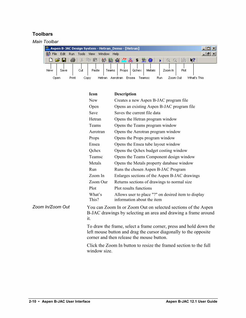
Icon Description New Creates a new Aspen B-JAC program file Open Opens an existing Aspen B-JAC program file Save Saves the current file data Hetran Opens the Hetran program window Teams Opens the Teams program window Aerotran Opens the Aerotran program window Props Opens the Props program window Ensea Opens the Ensea tube layout window Qchex Opens the Qchex budget costing window Teamsc Opens the Teams Component design window Metals Opens the Metals property database window Run Runs the chosen Aspen B-JAC Program Zoom In Enlarges sections of the Aspen B-JAC drawings Zoom Our Returns sections of drawings to normal size Plot Plot results functions What�s This?
Allows user to place "?" on desired item to display information about the item
You can Zoom In or Zoom Out on selected sections of the Aspen B-JAC drawings by selecting an area and drawing a frame around it.
To draw the frame, select a frame corner, press and hold down the left mouse button and drag the cursor diagonally to the opposite corner and then release the mouse button.
Click the Zoom In button to resize the framed section to the full window size.
Toolbars Main Toolbar
Zoom In/Zoom Out

Aspen B-JAC 12.1 User Guide Aspen B-JAC User Interface • 2-11
Icon Description Navigator Allows quick access to forms in the Menu Tree One Level Up
Takes the user up one level in the Menu Tree
Hide Folder List
Hides Navigator Menu Tree
Units Box Allow you to change globally the units of measure Go Back Takes the user to the most recently viewed form Go Forward Takes the user to the next form in the Menu Tree Previous Form
Takes the user to the previous form in the Menu Tree
Next Form Takes the user to the next form in the Menu Tree Next Takes the user to the next required input or result
sheet
The Next button guides you sequentially through the required input forms to complete the input for the problem. Note that subsequent steps are dependant upon your previous selections in the program. When you use the Next button, the program minimizes the input information required and uses program defaults.
Data Maintenance You can access the Units of Measure by selecting Tools in the Menu Bar and then selecting the Data Maintenance section. You can set the default units of measure to US, SI, or Metric and also set up your own customized set of units. In the Units Maintenance section you can customize the conversion factors used and the number of decimal point shown in the results.
Program Toolbar
Next
Units of Measure

2-12 • Aspen B-JAC User Interface Aspen B-JAC 12.1 User Guide
This function allows you to create a database with your standard exchangers sizes that can reference from the B-JAC design programs.
This item provides access to the Aspen B-JAC Props, chemical databank, and Priprops, the user private property databases. The Priprops program allows you to build your own private property databank that can be accessed form the Hetran, Aerotran, and Props programs. Reference the Priprops section of this manual for additional information.
This item provides access to the Aspen B-JAC Metals, material databank, and Primetals, the private property metals databases. The Primetals program allows you to build your own private property databank that can be accessed from the Hetran, Aerotran, and Teams programs. Reference the Primetals section of this manual for additional information.
This item provides access to the B-JAC Defmats, material defaults database for metals in the databanks. The Defmats program allows you to change the specified material specifications to be used when the generic material references are specified.
This item provides access to the Newcost fabrication standards and material pricing databases. Labor, fabrication standards, and material pricing may be customized your applications. For more information, see the Newcost Database section of this manual.
You can set a list of frequently used materials and/or chemical components for the databank search engines. This will allow to search for a material or component from your personalized list of items you use often.
Program Settings You can specify global program settings, which all Hetran programs can use. These global settings are available from the Tools menu. They include: • File Save Options
Set the auto-save file functions. You can set the program to save your file information every few minutes or at the time the program is executed.
• Company Logo By providing the reference to a Bitmap file, you can add your company logo to the program results and drawings.
• Default Units of Measure
Heat Exchanger Standards
Chemical Databank (B-JAC Props & Priprops)
Materials Databank (B-JAC Databank & Primetals)
Materials Defaults (Defmats)
Costing (Newcost Database)
Frequently Used Materials and Chemical Components

Aspen B-JAC 12.1 User Guide Aspen B-JAC User Interface • 2-13
You can set the default units of measure to US, SI, or Metric. Note that the units may be changed at any time in the Aspen B-JAC program window.
• Headings / Drawing Title You can set up the default headings and title block information that appears on the printed output and drawings.
• Nozzle size specification on drawings You can set the units set basis for the nozzle sizes shown on the drawings. For example, US unit size nozzles can be shown even though the drawings are in SI or metric units.
• Folder for customized database files You can specify a folder location for your customized database files. The B-JAC programs will then reference your customized database files in the specified folder in lieu of the standard database files in the program PDA folder.
• Excel templates You can specify an Excel template file to use for each program as a default. When you select File | Export | Excel, the specified default template is used.
• Heat exchanger standards You can set which exchanger standards database file is to be referenced.
• Advanced You can enable variable attributes so they will be shown in the Aspen B-JAC program prompt area. For example, set drag-drop format to move data to Excel; set the maximum disk space for temporary files.
Program Input Sheets are made up of input fields and their descriptions. For each field, the user (1) enters data, (2) chooses from a given list of options, or (3) checks the cell if appropriate. The cursor can be moved from one input field to another by using the Tab key, Enter key, arrow keys, or the mouse.
You can navigate through a input form by using the Tab key or Enter key which will take you to the next required input field or you can select the items with the mouse. To navigate through an input field grid, such as for physical properties, or nozzle connections, you can use the Enter key which will move the cursor down to the next field in a column, or you can use the arrow keys
Input Fields
2-14 • Aspen B-JAC User Interface Aspen B-JAC 12.1 User Guide
to direct the cursor, or you can use the mouse to select the input field.
The input fields consist of the following types: • User defined. You enter the value such as a temperature or
operating pressure. • User defined with suggested values. You can input a value or
select from a list of typical values for the input which are available in a drop down selection menu. You can access by the drop down menu by clicking on the input field with the mouse and then select the down arrow displayed. You can select an item in the drop down menu by using the up and down arrow keys or by selecting with the mouse.
• Available program selections. You select from a drop down menu list or options list displayed on the input form. You can select an item in the drop down menu by using the up and down arrow keys or by selecting with the mouse.
• Many of the input fields have graphical support. As you select from the available menu options, a sketch of the selection will appear next to the input field.
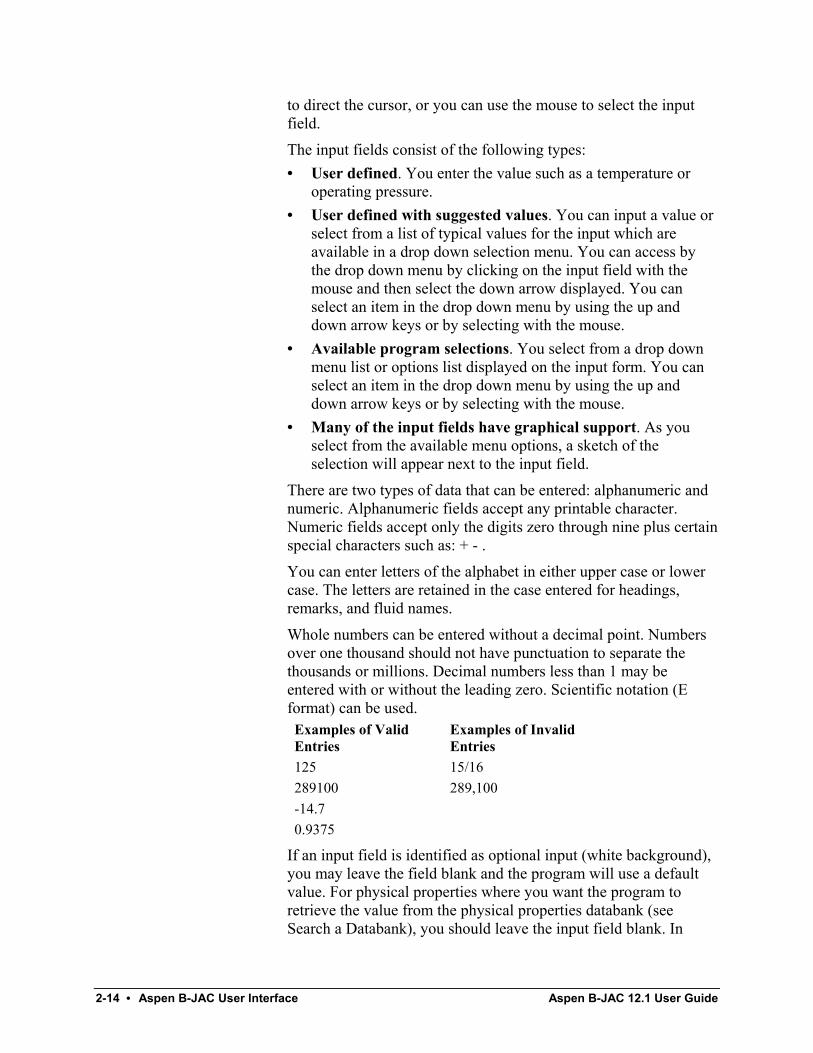
There are two types of data that can be entered: alphanumeric and numeric. Alphanumeric fields accept any printable character. Numeric fields accept only the digits zero through nine plus certain special characters such as: + - .
You can enter letters of the alphabet in either upper case or lower case. The letters are retained in the case entered for headings, remarks, and fluid names.
Whole numbers can be entered without a decimal point. Numbers over one thousand should not have punctuation to separate the thousands or millions. Decimal numbers less than 1 may be entered with or without the leading zero. Scientific notation (E format) can be used. Examples of Valid Entries
Examples of Invalid Entries
125 15/16 289100 289,100 -14.7 0.9375
If an input field is identified as optional input (white background), you may leave the field blank and the program will use a default value. For physical properties where you want the program to retrieve the value from the physical properties databank (see Search a Databank), you should leave the input field blank. In

Aspen B-JAC 12.1 User Guide Aspen B-JAC User Interface • 2-15
many cases, you can get additional descriptive information on an item by pressing F1, the Help key.
Required input fields will be identified by a green background color for the input field. Optional input fields will have a white background. Any inputted value that exceeds a normal range limit will be highlighted with a red background. Note that the program will still accept and use a value outside the normal range. If a folder or tab is not complete, a red X will be shown on the respective folder in the Navigation Tree and on the Tab label.
All of the Aspen B-JAC programs run in traditional U.S. units, SI units, and traditional metric units. The global setting for units is set in the Units Box located in the Tools Bar.
The programs allow you to dynamically change the system of measure used in the input or results sections. It is therefore possible to view and/or print the same solution in two different systems for easy comparison or checking.
Field specific units of measure control is also available. A specific set of units may be specified for each input data field by selecting from the units drop down menu next to the input field. The field specific units will override the global units set in the Units Box.
You can input the value in one set of units and then select an alternate unit from the drop down units menu, and the input value will be converted.
Please note that the solution of a design problem may be dependent upon the system of measure used in the input. This is due to differing standards in incrementing dimensions. This is especially true for the mechanical design programs.
You can search for an item in the Chemical Component or Material of Construction Databanks. Click on the Search button located on databank reference form to open the search utility.
To find an item in the list, type in the first few letters of the material name. Or, scroll through the material list using the up and down arrows to the right of the field. You can also specify a search preference, database, material class and material type. Click on the desired material. In the Component list, click on the desired component and press Set to match it with the selected reference. You can also erase a reference from the component list by clicking on the component and pressing Clear.
Units of Measure - Field Specific
Databank Reference

2-16 • Aspen B-JAC User Interface Aspen B-JAC 12.1 User Guide
The components in the databank have a component name which is up to 32 characters long, a chemical formula or material specification. You use these for the databank reference. We recommend that you do not use the chemical formula, because the formula may not be a unique reference. You should use the appropriate reference exactly as it appears in the databank directory.
After data is entered in an input field, the program will check the specified data against a high and low value range. If a value falls outside this range, the input field will turn red and a warning message will be displayed at the bottom left hand of the screen. This does not mean the program will not accept this data. It merely suggests that you should check the data for accuracy. If the data is correct, continue with data input.
Several of the programs have a form for change codes. You can use this form to insert four letter codes and numeric values to specify input data which is not included in the regular input screens. Refer to the Change Code section in the individual Program Guide. First type the change code, then an equals sign ("="), then the numeric value. For example: SENT=2.
Range Checks
Change Codes
Aspen B-JAC 12.1 User Guide Aspen B-JAC User Interface • 2-17
It also possible to provide a Super Change Code by defining the change codes to be applied to a design in a separate ASCII file and referencing the file as follows in the Change Code input field: File="Filename"
We suggest that you use the same input file for all Aspen B-JAC programs for a specific heat exchanger design problem. Save the input data in a convenient filename that can be accessed by all the Aspen B-JAC programs.
Using the Transfer function under the Run menu, you can add data to the input for use with other programs. For example, you can use Hetran to thermally design a shell and tube heat exchanger, and then request that the chosen design be transferred to another program such as Hetran into Aerotran, Hetran into Teams, or Teams into Ensea. In this way the appropriate design data is directly available to other programs.
This concept also makes it easy for you to compare design solutions in different types of heat exchangers. You can run Hetran to design a shell and tube heat exchanger and then, with very little additional input data, run Aerotran to design an air-cooled heat exchanger.
Program Output The primary output formats of the Aspen B-JAC programs are: • Display • Print • Drawings
Display Scroll through the forms in the Results folder of the navigation tree to evaluate the results of the program output. Each form may have multiple sheets, which you can display by clicking on the different tabs.
Print To print the results, choose Print from the File menu. On the Print dialog box, review the printing options, make any desired changes, and click OK.
The Database Concept

2-18 • Aspen B-JAC User Interface Aspen B-JAC 12.1 User Guide
Drawings • 2D CAD
The output of many Aspen B-JAC programs includes drawings. Drawings generated by the TEAMS program may be exported to CAD programs via a DXF file format.
• 3D Solid Model CAD Aspen Hetran Users can now create fully featured 3D solid models based on the Autodesk Inventor Tool, using the File | Export menu option. The interface allows the user to create models of individual components, groups of components, or the entire exchanger. Aspen Hetran 3D solid models provide a modern architecture from which the user can create sophisticated 2D drawings. Some dimensions used in the 3D Solid Model created from Aspen Hetran are estimated for example, tubesheet thickness. For a 3D Solid Model reflecting rigorous mechanical design calculations results and fabrication practices use Aspen Teams. Autodesk Inventor software can import and export both the STEP and IGES file formats as core functionality. It also supports the DWG, DXF�, and SAT (ACIS®) formats as well as 3D Studio VIZ®, and 3ds max� for output only. The Inventor CAD program must be loaded on your system to generate the drawings.
Help Facility The Aspen B-JAC software includes extensive help facilities, which have been designed to minimize the need for printed documentation.
You may access the help facility in the following ways: • General Help
This level includes information that applies to all of the Aspen B-JAC programs. You can access the general help index by selecting the Help button from the Menu Bar at any time in the program. You may select the Help Contents to select from the list of topics or you may search for Help on a specific topic.
• Field-specific general Help topic By selecting an input field with the mouse and then pressing the F1 key, the general help will open and display the information.
Getting Help

Aspen B-JAC 12.1 User Guide Aspen B-JAC User Interface • 2-19
• Field-specific "What�s This?" Help You can obtain input field specific help by selecting the What's This ? button on the Tool Bar and then pointing to the input field and clicking the mouse to display the information.
• Training From the Help menu, you can directly access the AspenTech Training web site. The site provides the latest information on training sessions being offered. You can also access Computer-Based Training sessions available for the B-JAC programs.
• Support From the Help menu, you can directly access the AspenTech Support web site. You can report support issues that will be reviewed by our technical support team. You can also access our Knowledge Base support area, an information source full of technical tips on using the B-JAC programs and answers to frequently asked questions.

2-20 • Aspen B-JAC User Interface Aspen B-JAC 12.1 User Guide

Aspen B-JAC 12.1 User Guide Aspen Hetran • 3-1
C H A P T E R 3
Aspen Hetran
Hetran Input Use this sheet to specify the following optional descriptive information: • Headings, which appear at the top of the TEMA specification
sheet, Input Summary results, and the Title block of the drawings. Headings are 1 to 5 lines of up to 75 characters per line. Note that only the first 40 characters of each line appear on the drawings.
• Fluid names, which appear with other input items to help you identify to which fluid the data applies. These names also appear in the specification sheet output. Although optional, we recommend specifying meaningful fluid descriptions. Each fluid name can be up to 19 characters long and can contain multiple words.
• Remarks, which appear at the bottom of the specification sheet output. Each line can be up to 75 characters long.
You can also create global headings for use by any B-JAC program on the Headings/Drawing tab of Program Settings under Tools.
Hetran Application Options Sheet
Problem Definition TEMA Specification Sheet Descriptions
Application Options

3-2 • Aspen Hetran Aspen B-JAC 12.1 User Guide
Use this sheet to specify these application options: • Hot Side Application
Select the application that describes the type of process condition that exists on the hot side. The selected application determines the required input data. For multi-component condensation applications, the program can calculate a condensation curve, or you can or specify the condensation heat release curve and properties. Most condenser types have the vapor and condensate flow in the same direction. The Knockback (reflux) condenser, which is often used to separate high and low boilers with minimal subcooling, has vapor entering the bottom of the unit with condensate falling back against the incoming vapor. With this type of condenser, you should consider using the differential condensation option if the program calculates the condensation curve.
• Cold side application Select the application that describes the type of process condition that exists on the cold side. The selected application determines the required input data. For multi-component vaporization, the program can calculate a vaporization curve, or you can or specify the vaporization heat release curve and properties. For narrow range and multi-component vaporization applications, you must select a vaporizer type.
• Location of hot fluid This required input identifies on which side to put the hot fluid: the shell side or tube side. During execution of the Aspen Hetran program , you can change the location of the hot fluid to compare the two possibilities.
• Program mode In design mode, the program selects the geometry. In rating mode, the program determines if the unit is over/under surfaced. In simulation mode, the program predicts outlet conditions. You can also specify an exchanger size standards file, and the Hetran program will select an exchanger size that satisfies the performance requirements.

Aspen B-JAC 12.1 User Guide Aspen Hetran • 3-3
Hot side application Select the application that describes the type of process condition that exists on the hot side: • Liquid, no phase change
This application covers a liquid phase fluid that does not change phase in the exchanger.
• Gas, no phase change This application covers a gas phase fluid that does not change phase in the exchanger.
• Narrow range condensation This application covers the cases where the condensing side film coefficient does not change significantly over the temperature range. Therefore, the calculations can be based on an assumed linear condensation profile. This class is recommended for cases of isothermal condensation and cases of multiple condensables without noncondensables where the condensing range is less than 6°C (10°F).
• Multi-component condensation This application covers the other cases of condensation where the condensing side film coefficient changes significantly over the condensing range. Therefore, the condensing range must be divided into several zones where the properties and conditions must be calculated for each zone. This class is recommended for all cases where noncondensables are present or where there are multiple condensables with a condensing range of more than 6°C (10°F). We recommend that you always use this application type when the Hetran file was created by Aspen Plus and condensation is occurring, even over a narrow range.
• Saturated steam This application covers the case where the hot side is pure steam, condensing isothermally.
• Falling film liquid cooler This application covers the case where the fluid is flowing downward and being cooled.
The selected application determines the required input data.

3-4 • Aspen Hetran Aspen B-JAC 12.1 User Guide
Cold side application Select the application that describes the type of process condition that exists on the cold side: • Liquid, no phase change
This application covers a liquid phase fluid that does not change phase in the exchanger.
• Gas, no phase change This application covers a gas phase fluid that does not change phase in the exchanger.
• Narrow range vaporization This application covers the cases where the vaporizing side film coefficient does not change significantly over the temperature range. Therefore, the calculations can be based on an assumed linear vaporization profile. This class is recommended for cases of single components and cases of multiple components where the vaporizing range is less than 6°C (10°F).
• Multi-component vaporization This application covers the other cases of vaporization where the vaporizing side film coefficient changes significantly over the vaporizing range. Therefore, the vaporizing range must be divided into several zones where the properties and conditions must be calculated for each zone. This class is recommended for cases where there are multiple components with a vaporizing range of more than 6°C (10°F). We recommend that you always use this application type when the Hetran file was created by Aspen Plus and vaporization is occurring, even over a narrow range.
The selected application determines the required input data.
Vaporizer type For narrow range and multi-component vaporization applications, select a vaporizer type: • Pool boiling
Pool boiling is restricted to the shell side and must be horizontal. It can be in a kettle or a conventional shell with a full bundle or a partial bundle where tubes are removed for disengagement space.
Aspen B-JAC 12.1 User Guide Aspen Hetran • 3-5
• Thermosiphon The thermosiphon can vaporize on the shell side (horizontal) or the tube side (vertical or horizontal). The hydraulics of the thermosiphon design are critical for proper operation. You can specify the relationship of the heat exchanger to the column and the associated piping in the input (see Thermosiphon Piping) or the program will select the piping arrangement and dimensions.
• Forced circulation Forced circulation can be on either shell or tube side. Here the fluid is pumped through and an allowable pressure drop is required input. This can be for a once through vaporizer.
• Falling film Falling film evaporation can be done only on the tube side in a vertical position where the liquid enters the top head and flows in a continuous film down the length of the tube. Part of the liquid is vaporized as it flows down the tube. Normally the vapor formed also flows down the tube due to the difference in pressure between the top head and the bottom head. This type of vaporizer helps minimize bubble point elevation and minimizes pressure drop.
Location of hot fluid This required input identifies on which side to put the hot fluid. During the execution of the Aspen Hetran program, you can change the location of hot fluid to compare the two possibilities.
Consider these guidelines to decide which side to put the hot fluid:
On this side Allocate these types of fluids
shell more viscous fluid cleaner fluid lower flow rate fluid
Tube more corrosive fluid higher pressure fluid higher temperature fluid dirtier fluid more hazardous fluid more expensive fluid

3-6 • Aspen Hetran Aspen B-JAC 12.1 User Guide
Program mode Select a program mode: • Design Mode
In design mode, you specify the performance requirements, and the program searches for a satisfactory heat exchanger configuration.
• Rating Mode In rating mode, you specify the performance requirements and the heat exchanger configuration, and the program checks to see if that heat exchanger is adequate.
• Simulation Mode In simulation mode, you specify the heat exchanger configuration and the inlet process conditions, and the program predicts the outlet conditions of the two streams.
• Select from standard file You specify a exchanger size standards file, which contains a list of standard heat exchanger sizes available to the user, and the program selects an exchanger size from the list that satisfies the performance requirements. The standard files can be generated from the Tools | Data Maintenance | Heat Exchanger Standards menu option.
Process Data Sheet Use this sheet to specify the process data relevant to the hot side and/or cold side fluids. The selected application determines the required data. • Fluid quantity, total - the total flow rates for the hot and cold
side streams. • Vapor quantity - the flow rates for the hot and cold side, inlet
and outlet vapor streams. • Liquid quantity - the flow rates for the hot and cold side, inlet
and outlet liquid streams. • Temperature (in/out) -hot and cold side inlet temperatures are
required. Simple condensation applications require hot and cold side temperatures. For other applications the outlet temperature can be optional if sufficient data has been specified to calculate the heat load.
• Dew / Bubble point - the hot and cold side inlet dew point temperature and the hot and cold side outlet bubble point temperature, at a specified operating pressure.
Process Data

Aspen B-JAC 12.1 User Guide Aspen Hetran • 3-7
• Operating pressure (absolute) - the absolute (not gauge) pressure. Depending on the application, the program may permit either inlet or outlet pressure to be specified. In most cases, it should be the inlet pressure.
• Heat exchanged - the total heat exchanged, which should be specified when designing to a specific heat duty.
• Allowable pressure drop - the maximum pressure drop permitted on the hot and cold sides. Where applicable, the allowable pressure drop is required. You can specify any value up to the operating pressure, although the allowable pressure drop should usually be less than 40% of the operating pressure.
• Fouling resistance - the hot and cold side fouling resistance. The fouling resistance defaults to zero if unspecified. You can specify any reasonable value. The program provides a list of typical values.
Fluid Quantity, Total Specify the total flow rate for no phase fluid.
For no phase change applications: if flow rates are not specified, the program calculates the required flow rates to meet the specified heat load or the heat load on the opposite side. All temperatures must be specified if the flow rates are omitted.
For phase change applications: the total flow rate should be approximated. The program still calculates the total required flow rate to balance the heat loads.
Temperature (in/out) You must specify the hot and cold side inlet/outlet temperatures.
Simple condensation applications require hot side outlet and cold side outlet temperatures. For other applications the outlet temperature can be optional if sufficient data has been specified to calculate the heat load.
For no phase change applications: specify the inlet temperature and flowrate. The program can calculate the outlet temperature based on the specified heat load or the heat load on the opposite side.
For narrow condensation and vaporization applications: specify an outlet temperature and associated vapor and liquid flows. This represents the second point on the VLE curve, which we assume to be a straight line. With this information, the program can determine the correct vapor/liquid ratio at various temperatures and

3-8 • Aspen Hetran Aspen B-JAC 12.1 User Guide
correct the outlet temperature or total flow rates to balance heat loads.
Operating Pressure (absolute) Specify the absolute (not gauge) pressure. Depending on the application, the program may permit specifying either inlet or outlet pressure. In most cases, it should be the inlet pressure.
For a thermosiphon reboiler, the operating pressure should reflect the pressure at the surface of the liquid in the column.
For condensers and vaporizers: in the case where you expect the pressure drop to significantly change the condensation or vaporization curves, you should use a pressure drop adjusted vapor-liquid equilibrium data. If the program calculates the curve, you can indicate adjusting the curve for pressure drop.
Heat Exchanged Specify a value for the total heat exchanged when designing to a specific heat duty.
If the heat exchanged is specified, the program compares the hot and cold side calculated heat loads with the specified heat load. If they do not agree within 2%, the program corrects the flow rate, or outlet temperature.
If the heat exchanged is not specified, the program compares the hot and cold side calculated heat loads. If they do not agree within 2%, the program corrects the flow rate, or outlet temperature.
To determine how the program handles heat load imbalances, click the Heat Load Balance Options tab and set the heat load adjustment options to have the program change flow rate, outlet temperature, or to allow an unbalanced heat load.
Heat Load Balance Options Sheet The heat load adjustment options determine how the program handles heat load imbalances.
Use this sheet to specify whether to adjust the total flowrate or the outlet temperature to balance the heat load against the specified heat load or the heat load calculated from the opposite side. The program calculates the required adjustment.
If you select no adjustment, the program designs the exchanger with the specified flows and temperatures, but with the highest of the specified or calculated heat loads.

Aspen B-JAC 12.1 User Guide Aspen Hetran • 3-9
Databanks Sheet Use this sheet to specify the source of the properties.
Properties from B-JAC Databank / User Specified properties / Interface properties from Aspen Plus Selecting this option (default), allows you to reference the B-JAC Property Databank, specify your own properties in the Hot Side and Cold property sections, or have properties passed into the B-JAC file directly from an Aspen Plus simulation program.
Note: Any properties specified in the property sections override properties coming from a property databank.
The B-JAC Property Databank consists of over 1500 compounds and mixtures used in the chemical process, petroleum, and other industries. You can reference the database by entering the components for the Hot Side and/or Cold Side streams in the Composition sections. Click the Search Database button to locate the components in the database.
If you specify properties in the Hot Side and/or Cold Side property sections, do not reference any compounds in the Hot Side and/or Cold Side Composition sections unless you plan to use both the B-JAC Databank properties and specified properties.
Properties passed into the B-JAC file from the Interface to an Aspen Plus simulation run are displayed in the Hot Side and/or Cold Side Property sections. If you pass in properties from Aspen Plus, do not specify a reference to Aspen Plus to an Aspen Properties file, since properties are already provided by the Aspen Plus interface in the specified property sections.
Aspen Properties Databank Aspen B-JAC provides access to the Aspen Properties physical property databank of compounds and mixtures.
If you are referencing the Aspen Properties databank, specify the flash option you want the Aspen Properties program to use with the VLE generation. The default is Vapor-Liquid. For more information see the Aspen Properties Users Guide.
To access the databank, first create an Aspen input file with stream information and physical property models. Run Aspen Plus and create the property file, xxxx.APPDF.
On the Databanks sheet specify the flash option and the name of the property file. If the file is not located in the same directory as
Physical Property Data Property Options

3-10 • Aspen Hetran Aspen B-JAC 12.1 User Guide
your B-JAC input file, use the browse button to set the correct path to the *.APPDF file
Then specify the composition of the stream in the Property Composition section. When the B-JAC program is executed, the Aspen Properties program is accessed and the properties are passed back to the B-JAC design file.
Condensation Options Sheet Use this sheet to specify the following options: • Condensation curve calculation method
The calculation method determines which correlations the program uses to determine the vapor-liquid equilibrium. The choice of method is dependent on the degree of non-ideality of the vapor and liquid phases and the amount of data available.
• Condensation curve calculation type For a condensing stream, you should determine if your case is closer to integral or differential condensation. The program defaults to integral.
• Effect of pressure drop on condensation The program defaults to calculating the condensing curve in isobaric conditions (constant operating pressure). If the B-JAC Property program generates the VLE curve, you may specify non-isobaric conditions. The program allocates the specified pressure drop based on temperature increments along the condensation/vaporization curve. The vapor/liquid equilibrium at various temperature points is calculated using an adjusted operating pressure.
• Estimated pressure drop for hot side Specify the estimated hot side pressure drop through the exchanger. If actual pressure varies more than 20 percent from this estimated pressure drop, adjust this value to the actual and rerun Hetran. If the B-JAC Property program generates the VLE curve, the program uses this pressure drop to adjust the VLE curve. The VLE calculation program does not permit the condensate to re-flash. If calculations indicate that this is happening, the program will suggest using a lower estimated pressure drop.
Condensation/Vaporization Curve Calculation Method The calculation method determines which correlations the program will use to determine the vapor-liquid equilibrium. The choice of

Aspen B-JAC 12.1 User Guide Aspen Hetran • 3-11
method is dependent on the degree of non-ideality of the vapor and liquid phases and the amount of data available.
The methods can be divided into three general groups: • Ideal - correlations for ideal mixtures.
The ideal method uses ideal gas laws for the vapor phase and ideal solution laws for the liquid phase. You should use this method when you do not have information on the degree of nonideality. This method allows for up to 50 components.
• Soave-Redlich-Kwong, Peng-Robinson, and Chao-Seader - correlations for non-ideal mixtures which do not require interaction parameters. The Soave-Redlich-Kwong and Peng-Robinson methods can be used on a number of systems containing hydrocarbons, nitrogen, carbon dioxide, carbon monoxide, and other weakly polar components. They can also be applied with success to systems which form an azeotrope, and which involve associating substances such as water and alcohols. They can predict vapor phase properties at any given pressure. The Chao-Seader method uses Redlich-Kwong equations for vapor phase non-ideality and an empirical correlation for liquid phase non-ideality. It is used with success in the petroleum industry. It is recommended for use at pressures less than 68 bar (1000 psia) and temperatures greater than -18°C (0°F). The program uses the original Chao-Seader correlation with the Grayson-Streed modification. There is no strict demarcation between these two methods since they are closely related. These methods allow for up to 50 components.
• Uniquac, Van Laar, Wilson, and NRTL - correlations for non-ideal mixtures which require interaction parameters. These methods are limited to ten components. The Uniquac, Van Laar, Wilson, and NRTL methods require binary interaction parameters for each pair of components. The Uniquac method also requires a surface parameter and volume parameter, and the NRTL method requires an additional Alpha parameter. The Wilson method is particularly suitable for strongly non-ideal binary mixtures, for example, solutions of alcohols with hydrocarbons. The Uniquac method is applicable for both vapor-liquid equilibrium and liquid-liquid equilibrium (immiscibles). It can be used for solutions containing small or large molecules, including polymers. In addition, Uniquac interaction parameters are less temperature dependent than those for Van Laar and Wilson.

3-12 • Aspen Hetran Aspen B-JAC 12.1 User Guide
Condensation Curve Calculation Type For a condensing stream, you should determine if your case is closer to integral or differential condensation.
Integral condensation assumes that the vapor and liquid condensate are kept close enough together to maintain equilibrium, and that the condensate formed at the beginning of the condensing range is carried through with the vapor to the outlet. Vertical tube side condensation is the best case of integral condensation. Other cases which closely approach integral condensation are: horizontal tube side condensation, vertical shell side condensation, and horizontal shell side crossflow condensation (X-shell).
In differential condensation the liquid condensate is removed from the vapor, thus changing the equilibrium and lowering the dew point of the remaining vapor. The clearest case of differential condensation is seen in the knockback reflux condenser, where the liquid condensate runs back toward the inlet while the vapor continues toward the outlet.
Shell side condensation in a horizontal E or J shell is somewhere between true integral condensation and differential condensation. If you want to be conservative, treat these cases as differential condensation. However, the industry has traditionally designed them as integral condensation.
More condensate will be present at any given temperature with integral condensation versus differential condensation. In the heat exchanger design, this results in a higher mean temperature difference for integral condensation compared to differential condensation.
The program defaults to integral.
Vaporization Options Sheet Use this sheet to specify the following options: • Vaporization curve calculation method
The calculation method determines which correlations the program uses to determine the vapor-liquid equilibrium. The choice of method is dependent on the degree of non-ideality of the vapor and liquid phases and the amount of data available.
• Effect of pressure drop on vaporization The program defaults to calculating the vaporization curve in isobaric conditions (constant operating pressure). If the B-JAC Property program generates the VLE curve, you may specify non-isobaric conditions. The program allocates the specified pressure drop based on temperature increments along the

Aspen B-JAC 12.1 User Guide Aspen Hetran • 3-13
condensation/vaporization curve. The vapor/liquid equilibrium at various temperature points is calculated using an adjusted operating pressure.
• Estimated pressure drop for cold side Specify the estimated cold side pressure drop through the exchanger. The program uses this pressure drop to adjust the VLE curve. If actual pressure varies more than 20% from this estimated pressure drop, adjust this value to the actual and rerun Hetran.
Property Methods Sheet Use this sheet to specify the following methods: • Property Method Hot & Cold Sides
Select the property method you wish to be used in the Aspen Properties program. Several property methods are available: • Ideal gas law • Equation of state • Interactive parameter • For additional information, please reference the Aspen
Properties User Guide. B-JAC calls and executes the Aspen Properties program and applies the selected property method to generate the VLE and physical property data required to design the exchanger.
• Free Water Method Hot & Cold Sides Lets you specify the property method for the free-water phase. Steam tables are recommended. For additional information, please reference the Aspen Properties User Guide. B-JAC calls and executes the Aspen Properties program and applies the selected property method to generate the VLE and physical property data needed to design the exchanger.
• Solubility Hot & Cold Sides Specify the solubility factor to be used. For additional information, please reference the Aspen Properties User Guide. B-JAC calls and executes the Aspen Properties program and applies the selected property method to generate the VLE and physical property data needed to design the exchanger.
• Flash Options Hot & Cold Sides Specify which flash phase option is to be used. For additional information, please reference the Aspen Properties User Guide. B-JAC calls and executes the Aspen Properties program and applies the selected property method to generate the VLE and physical property data needed to design the exchanger.
3-14 • Aspen Hetran Aspen B-JAC 12.1 User Guide
Composition Sheet If the stream physical properties are being accessed from the Aspen B-JAC databank or if the program is calculating a vapor/liquid equilibrium curve (B-JAC Props or Aspen Properties); use this sheet to define the stream composition.
Select the composition specification - weight flow rate or %, mole flow rate or %, volume flow rate or % - to determine the basis of the mixture physical properties calculations. Then use the table to define the stream composition: • Components
List the components in the stream here if you want to access the B-JAC database for properties. Component names must match the compound name listed in the B-JAC database. Click the Search Databank button to scan and select compounds from the databank. If you are supplying the stream physical properties and VLE (for phase change) in the Hot Side and/or Cold Side properties section, do not list any components here. When the program is calculating a vapor/liquid equilibrium curve, you can specify individual component physical properties by selecting User in the Source field. In this case the component field is used to identify the component in the results.
• Vapor in, Liquid in, Liquid out These fields identify the composition of the stream in each phase and is dependant on the Composition Specification. You must specify the inlet compositions if referencing the databank for physical properties. If outlet compositions are not specified, the program assumes the same composition as the inlet. The data for each column is normalized to calculate the individual components fraction.
• Component Type Use this field to specify noncondensables and immiscible components in the stream for all complex condensing applications. If a component does not condense any liquid over the temperature range in the exchanger, it is best to identify it as a noncondensable. If a component is immiscible with the other stream components, it needs to be identified so the condensation VLE can be adjusted. If the field is left blank, the program attempts to determine if a component is a noncondensable but does not try to identify any immiscibles.
Hot Side Composition
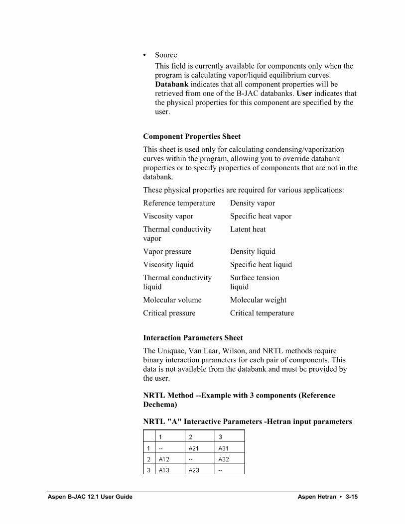
Aspen B-JAC 12.1 User Guide Aspen Hetran • 3-15
• Source This field is currently available for components only when the program is calculating vapor/liquid equilibrium curves. Databank indicates that all component properties will be retrieved from one of the B-JAC databanks. User indicates that the physical properties for this component are specified by the user.
Component Properties Sheet This sheet is used only for calculating condensing/vaporization curves within the program, allowing you to override databank properties or to specify properties of components that are not in the databank.
These physical properties are required for various applications:
Reference temperature Density vapor
Viscosity vapor Specific heat vapor
Thermal conductivity vapor
Latent heat
Vapor pressure Density liquid
Viscosity liquid Specific heat liquid
Thermal conductivity liquid
Surface tension liquid
Molecular volume Molecular weight
Critical pressure Critical temperature
Interaction Parameters Sheet The Uniquac, Van Laar, Wilson, and NRTL methods require binary interaction parameters for each pair of components. This data is not available from the databank and must be provided by the user.
NRTL Method --Example with 3 components (Reference Dechema)
NRTL "A" Interactive Parameters -Hetran input parameters

3-16 • Aspen Hetran Aspen B-JAC 12.1 User Guide
NRTL "Alpha" Parameters �Hetran input parameters
Alpha 12 = Alpha 21 Alpha 13 = Alpha 31 Alpha 23 = Alpha 32
NRTL � Conversion from Aspen Properties parameters to Hetran parameters: Aspen Properties NRTL Parameters � The parameters AIJ, AJI, DJI, DIJ, EIJ, EJI, FIJ, FJI, TLOWER, & TUPPER in Aspen Properties (not shown in the following example) are not required for the Hetran NRTL method.
Aspen Properties NRTL Interactive Parameters
"A" Interactive Parameters � Conversion from Aspen Properties to Hetran
"Alpha" Parameters � Conversion from Aspen Properties to Hetran

Aspen B-JAC 12.1 User Guide Aspen Hetran • 3-17
NRTL - Alpha parameters The NRTL method requires binary interaction parameters for each pair of components and an additional Alpha parameter. This data is not available from the databank.
Uniquac - Surface & Volume parameters The Uniquac method requires binary interaction parameters for each pair of components and also needs a surface parameter and volume parameter. This data is not available from the databank.
Hot Side Properties Use these sheets to specify the physical properties that are required for the hot side fluids: • VLE • Vapor • Liquid • Noncondensable
Properties specified here override data coming from the B-JAC Property Database or Aspen Properties programs.
VLE Properties Sheet If you are entering a vapor-liquid equilibrium curve, you must specify multiple temperature points on the curve encompassing the expected inlet and outlet temperatures of the exchanger. The dew and bubble points of the stream are recommended.
Condensation curves require the dew point and vaporization curves require the bubble point. The first point on the curve does not have to agree with the inlet temperature, although it is recommended. For simulation runs, it is best to specify the curve down to the inlet temperature of the opposite side.
You can specify one temperature point or as many as 13 temperature points. The temperatures entered for no phase change fluids should at least include both the inlet and outlet temperatures. The inlet temperature of the opposite side fluid should also be included as a third temperature point for viscous fluids. Multiple temperature points, including the inlet and outlet, should be entered when a change of phase is present.
For each temperature point you must specify a parameter defining the heat load. For heat load specify cumulative heat load, incremental heat load, or enthalpies.
Hot Side Properties

3-18 • Aspen Hetran Aspen B-JAC 12.1 User Guide
For each temperature point you must also specify a parameter defining the vapor/liquid composition. For the composition, you may specify vapor flow rate, liquid flow rate, vapor mass fraction, or liquid mass fraction.
The program calculates the other parameters based on the entry and the total flow specified under process data. Vapor and liquid mass fractions are recommended because they are independent of flow rates. For complex condensers, the composition should be the total vapor stream including noncondensables.
Liquid and Vapor Properties Sheets The type of application determines the required properties. Most properties are self-explanatory.
If you are referencing the databank for a fluid, you do not need to enter any data on the corresponding physical properties input sheets. However, even if you are referencing the databank, you can also specify any property. The specified property overrides the value from the databank.
Specific Heat Specify the specific heat for the component at the referenced temperature.
Thermal Conductivity Specify the thermal conductivity for the component at the referenced temperature.
Viscosity The viscosity requested is the dynamic (absolute) viscosity in centipoise or mPa*s (note that centipoise and mPa*s are equal). To convert kinematic viscosity in centistokes to dynamic viscosity in centipoise or mPa*s, multiply centistokes by the specific gravity.
The program uses a special logarithmic formula to interpolate or extrapolate the viscosity to the calculated tube wall temperature. However, when a liquid is relatively viscous, say greater than 5 mPa*s (5 cp), and especially when it is being cooled, the accuracy of the viscosity at the tube wall can be very important for calculating an accurate film coefficient. In these cases, you should specify the viscosity at a third point, which extends the viscosity points to encompass the tube wall temperature. This third temperature point may extend to as low (if being cooled) or as high (if being heated) as the inlet temperature on the other side.

Aspen B-JAC 12.1 User Guide Aspen Hetran • 3-19
Density Be sure to specify density and not specific gravity. Convert specific gravity to density by using the appropriate formula:
density, lb/ft3 = 62.4 * specific gravity density, kg/m3 = 1000 * specific gravity
The density can also be derived from the API gravity, using this formula:
density, lb/ft3 = 8829.6 / ( API + 131.5 )
Surface Tension Surface tension is required for vaporizing fluids. If you do not have surface tension information available, the program estimates a value.
Latent Heat Provide latent heat for change of phase applications.
Molecular Weight Provide the molecular weight of the vapor for change of phase applications.
Diffusivity The diffusivity of the vapor is used in the determination of the condensing coefficient for the mass transfer method. Therefore, provide this property if data is available. If not known, the program estimates a value.
Noncondensable Sheet Noncondensables are those vapor components in a condensing stream, which do not condense in any significant proportions at the expected tube wall temperature. Examples include hydrogen, CO2, Air, CO.
Noncondensables require the following properties: • Specific Heat • Thermal Conductivity • Viscosity • Density • Molecular Weight • Molecular Volume
These properties can be specified or referenced from the database.

3-20 • Aspen Hetran Aspen B-JAC 12.1 User Guide
The noncondensable flow rate is required if it has not been defined in the databank composition input.
Cold Side Composition Sheet If the stream physical properties are being accessed from the Aspen B-JAC databank or if the program is calculating a vapor/liquid equilibrium curve (B-JAC Props or Aspen Properties); use this sheet to define the stream composition.
Select the composition specification - weight flow rate or %, mole flow rate or %, volume flow rate or % - to determine the basis of the mixture physical properties calculations. Then use the table to define the stream composition: • Components
List the components in the stream here if you want to access the B-JAC database for properties. Component names must match the compound name listed in the B-JAC database. Click the Search Databank button to scan and select compounds from the databank. If you are supplying the stream physical properties and VLE (for phase change) in the Hot Side and/or Cold Side properties section, do not list any components here. When the program is calculating a vapor/liquid equilibrium curve, you can specify individual component physical properties by selecting User in the Source field. In this case the component field is used to identify the component in the results.
• Liquid in, Vapor in, Vapor out These fields identify the composition of the stream in each phase and is dependant on the Composition Specification. You must specify the inlet compositions if referencing the databank for physical properties. If outlet compositions are not specified, the program assumes the same composition as the inlet. The data for each column is normalized to calculate the individual components fraction.
• Component Type Use this field to specify any inert in the stream. If the field is left blank, the program attempts to determine if a component is an inert.
• Source This field is currently available for components only when the program is calculating vapor/liquid equilibrium curves. Databank indicates that all component properties will be retrieved from one of the B-JAC databanks. User indicates that
Cold Side Composition

Aspen B-JAC 12.1 User Guide Aspen Hetran • 3-21
the physical properties for this component are specified by the user.
Component Properties Sheet This sheet is used only for calculating condensing/vaporization curves within the program, allowing you to override databank properties or to specify properties of components that are not in the databank.
These physical properties are required for various applications:
Reference temperature Density vapor
Viscosity vapor Specific heat vapor
Thermal conductivity vapor
Latent heat
Vapor pressure Density liquid
Viscosity liquid Specific heat liquid
Thermal conductivity liquid
Surface tension liquid
Molecular volume Molecular weight
Critical pressure Critical temperature
Interaction Parameters Sheet The Uniquac, Van Laar, Wilson, and NRTL methods require binary interaction parameters for each pair of components. This data is not available from the databank and must be provided by the user.
NRTL Method --Example with 3 components (Reference Dechema)
NRTL "A" Interactive Parameters -Hetran input parameters

3-22 • Aspen Hetran Aspen B-JAC 12.1 User Guide
NRTL "Alpha" Parameters �Hetran input parameters
Alpha 12 = Alpha 21 Alpha 13 = Alpha 31 Alpha 23 = Alpha 32
NRTL � Conversion from Aspen Properties parameters to Hetran parameters: Aspen Properties NRTL Parameters � The parameters AIJ, AJI, DJI, DIJ, EIJ, EJI, FIJ, FJI, TLOWER, & TUPPER in Aspen Properties (not shown in the following example) are not required for the Hetran NRTL method.
Aspen Properties NRTL Interactive Parameters
"A" Interactive Parameters � Conversion from Aspen Properties to Hetran
"Alpha" Parameters � Conversion from Aspen Properties to Hetran
Aspen B-JAC 12.1 User Guide Aspen Hetran • 3-23
NRTL - Alpha parameters The NRTL method requires binary interaction parameters for each pair of components and an additional Alpha parameter. This data is not available from the databank.
Uniquac - Surface & Volume parameters The Uniquac method requires binary interaction parameters for each pair of components and also needs a surface parameter and volume parameter. This data is not available from the databank.
Cold Side Properties Form Use these sheets to specify the physical properties that are required for the cold side fluids: • VLE • Liquid • Vapor • Pressure Correction
Properties specified here override data coming from the B-JAC Property Database or Aspen Properties programs.
VLE Properties Sheet If you are entering a vapor-liquid equilibrium curve, you must specify multiple temperature points on the curve encompassing the expected inlet and outlet temperatures of the exchanger. The dew and bubble points of the stream are recommended.
Condensation curves require the dew point and vaporization curves require the bubble point. The first point on the curve does not have to agree with the inlet temperature, although it is recommended. For simulation runs, it is best to specify the curve down to the inlet temperature of the opposite side.
You can specify one temperature point or as many as 13 temperature points. The temperatures entered for no phase change fluids should at least include both the inlet and outlet temperatures. The inlet temperature of the opposite side fluid should also be included as a third temperature point for viscous fluids. Multiple temperature points, including the inlet and outlet, should be entered when a change of phase is present.
For each temperature point you must specify a parameter defining the heat load. For heat load specify cumulative heat load, incremental heat load, or enthalpies.
Cold Side Properties

3-24 • Aspen Hetran Aspen B-JAC 12.1 User Guide
For each temperature point you must also specify a parameter defining the vapor/liquid composition. For the composition, you may specify vapor flow rate, liquid flow rate, vapor mass fraction, or liquid mass fraction.
The program calculates the other parameters based on the entry and the total flow specified under process data. Vapor and liquid mass fractions are recommended because they are independent of flow rates. For complex condensers, the composition should be the total vapor stream including noncondensables.
Liquid and Vapor Properties (Cold Side) The type of application determines the required physical properties. Most properties are self-explanatory.
If you are referencing the databank for a fluid, you do not need to enter any data on the corresponding physical properties input sheets. However, you can specify any property, even if you are referencing the databank. The specified property overrides the value from the databank.
Specific Heat Provide the specific heat for the component at the referenced temperature.
Thermal Conductivity Provide the thermal conductivity for the component at the referenced temperature.
Viscosity The viscosity requested is the dynamic (absolute) viscosity in centipoise or mPa*s (note that centipoise and mPa*s are equal). To convert kinematic viscosity in centistokes to dynamic viscosity in centipoise or mPa*s, multiply centistokes by the specific gravity.
The Aspen Hetran program uses a special logarithmic formula to interpolate or extrapolate the viscosity to the calculated tube wall temperature. However when a liquid is relatively viscous, say greater than 5 mPa*s (5 cp), and especially when it is being cooled, the accuracy of the viscosity at the tube wall can be very important to calculating an accurate film coefficient. In these cases, you should specify the viscosity at a third point, which extends the viscosity points to encompass the tube wall temperature. This third temperature point may extend to as low (if being cooled) or as high (if being heated) as the inlet temperature on the other side.

Aspen B-JAC 12.1 User Guide Aspen Hetran • 3-25
Density Be sure to specify density and not specific gravity. Convert specific gravity to density by using the appropriate formula:
density, lb/ft3 = 62.4 * specific gravity density, kg/m3 = 1000 * specific gravity.
The density can also be derived from the API gravity, using this formula:
density, lb/ft3 = 8829.6 / ( API + 131.5 )
Surface Tension Surface tension is required for vaporizing fluids. If you do not have surface tension information available, the program estimates a value.
Molecular Weight Specify the molecular weight of the vapor for change of phase applications.
Pressure Correction Properties Sheet Use this sheet to make these pressure corrections: • Vaporization curve adjustment for pressure
For certain applications (e.g., thermosiphon reboilers, pool boilers), it is advisable to adjust the vaporization curve for pressure changes during the analysis of the exchanger. This input specifies the type of adjustment to be made.
• Reference pressure For vaporization applications, a second reference pressure with the corresponding bubble and/or dew point(s) is recommended. Using this data, the program can determine the change in bubble point temperature with the change in pressure. This is used to correct the vaporization curve for pressure changes.
• Bubble point at reference pressure For vaporization applications, a bubble point at reference pressure may be optionally specified. The bubble point at reference pressure and bubble point at operating pressure are used to determine the change in bubble point temperature with change in pressure. This is used to correct the vaporization curve for pressure changes.
• Dew point at reference pressure For vaporization applications, a dew point at reference pressure may be optionally specified. The dew point at reference

3-26 • Aspen Hetran Aspen B-JAC 12.1 User Guide
pressure and dew point at operating pressure are used to determine the change in dew point temperature with change in pressure. This is used to correct the vaporization curve for pressure changes.
Shell/Heads Sheet Use this sheet to specify the shell and head types and exchanger position. • Front head type
The front head type should be selected based on the service needs for the exchanger. A full access cover provided in the A, C, and N type heads may be needed if the tube side of the exchanger must be cleaned frequently. Type B (default) is generally the most economical type head.
• Shell type The shell type determines the shell side flow arrangement and the place of the shell side nozzles. The default is type E (except K type shell side pool boilers).
• Rear head type The rear head type affects the thermal design, because it determines the outer tube limits and therefore the number of tubes and the required number of tube passes. Type U is the default for kettle shells; for all others, M.
• Exchanger position Specify whether the exchanger is to be installed in the horizontal or vertical position. The default is vertical for tube side thermosiphon; for all others, horizontal.
Shell type The shell type determines the shell side flow arrangement and the place of the shell side nozzles. Type Description
E Generally provides the best heat transfer but also the highest shell side pressure drop. Used for temperature cross applications where pure counter current flow is needed.
F This two pass shell can enhance shell side heat transfer and also maintain counter current flow if needed for temperature cross applications.
G Will enhance the shell side film coefficient for a given exchanger size.
Exchanger Geometry Exchanger Type

Aspen B-JAC 12.1 User Guide Aspen Hetran • 3-27
Type Description
H A good choice for low shell side operating pressure applications. Pressure drop can be minimized. Used for shell side thermosiphons.
J Used often for shell side condensers. With two inlet vapor nozzles on top and the single condensate nozzle on bottom, vibration problems can be avoided.
K Used for kettle type shell side reboilers. X Good for low shell side pressure applications. Units is
provided with support plates which provides pure cross flow through the bundle. Multiple inlet and outlet nozzles or flow distributors are recommended to assure full distribution of the flow along the bundle.
V This type is not currently part of the TEMA standards. It is used for very low shell side pressure drops. It is especially well suited for vacuum condensers. The vapor belt is an enlarged shell over part of the bundle length.
Default: E type (except K type shell side pool boilers)
Covers Exchanger Type Use this sheet to specify the type of covers. • Front cover type
The front cover type appears only when you specify a B type front head. A flat bolted cover is assumed for the other front head types. This is included for the accuracy of the cost estimate and a more complete heat exchanger specification. The default is ellipsoidal.
• Cover welded to a cylinder The cover welded to a cylinder option determines if there is a cylinder between the front head flange (or tubesheet in the case of a hemispherical cover) and the attached cover. This is included for the accuracy of the cost estimate and a more complete heat exchanger specification. The default is yes, except when the cover is hemispherical.
• Rear cover type The rear cover type is based on the selected rear head type. The flat bolted cover is for L, N, P and W type rear heads. The flat welded and form covers (except for the dished cover) are available on the M type rear heads. The dished and ellipsoidal is available on the S and T rear heads. This is included for accuracy of the cost estimate and a more complete heat exchanger specification. The defaults are: flat bolted for L, N, P, or W types; ellipsoidal for M type; dished for S or T type.

3-28 • Aspen Hetran Aspen B-JAC 12.1 User Guide
• Cover welded to a cylinder The cover welded to a cylinder option only applies to M type rear heads. For other cases it is ignored. It determines if there is a cylinder between the rear head flange (or tubesheet in the case of a hemispherical cover) and the attached cover. This is included for the accuracy of the cost estimate and a more complete heat exchanger specification. The default is yes, except when the cover is hemispherical.
• Shell cover type A shell cover type should be specified for a U-tube, S, or T type rear head exchangers. Shell cover may be welded directly to shell cylinder or bolted to the shell cylinder with a pair of mating body flanges. The default is Ellipsoidal for U-tube, S, T type rear heads.
Tubesheets/Expansion Joints Sheet Use this sheet to specify: • Tubesheet type
The tubesheet type has a very significant effect on both the thermal design and the cost.
• Tube to tubesheet joint The tube to tubesheet joint does not affect the thermal design, but it does have a small effect on the mechanical design and sometimes a significant effect on the cost.
• Expansion joint The specification of an expansion joint does not affect the thermal design calculations, but does have a significant effect on the cost. This item only applies to fixed tubesheet heat exchangers; it is ignored for all other types. The default is program, based on the estimated differential expansion. Note that the calculations required to determine the need for an expansion joint are quite complex and are beyond the scope of the Hetran program. These calculations are part of the Teams program. However the Hetran program will estimate the differential expansion between the tubes and the shell and make a simple determination on the need for an expansion joint if you use the program default.
Tubesheet type The tubesheet type has a very significant effect on both the thermal design and the cost. The default is normal single tubesheet(s).

Aspen B-JAC 12.1 User Guide Aspen Hetran • 3-29
Double tubesheets are used when it is extremely important to avoid any leakage between the shell and tube side fluids. Double tubesheets are most often used with fixed tubesheet exchangers, although they can also be used with U-tubes and outside packed floating heads.
Double tubesheets shorten the length of the tube which is in contact with the shell side fluid and therefore reduce the effective surface area. They also affect the location of the shell side nozzles and the possible baffle spacings.
The gap type double tubesheet has a space, usually about 150 mm (6 in.), between the inner (shell side) and outer (tube side) tubesheets. The integral type double tubesheet is made by machining out a honeycomb pattern inside a single thick piece of plate so that any leaking fluid can flow down through the inside of the tubesheet to a drain. This type is rare, since it requires special fabrication tools and experience.
Tube to tubesheet joint The tube to tubesheet joint does not affect the thermal design, but it does have a small effect on the mechanical design and sometimes a significant effect on the cost.
The most common type of tube to tubesheet joint is expanded only with 2 grooves. Although TEMA Class C allows expanded joints without grooves, most fabricators will groove the tube holes whenever the tubes are not welded to the tubesheet.
For more rigorous service, the tube to tubesheet joint should be welded. The most common welded joints are expanded and seal welded with 2 grooves and expanded and strength welded with 2 grooves.
For normal service the default is expanded only with 2 grooves; for lethal service the default is expanded and strength welded with 2 grooves.
Flanges Sheet The body flange type refers to the type of flanges that are attached to the shell cylinder for the shell side and the head cylinder(s) for the tube side. This item can have a significant effect on the cost. The shell side body flange type (applicable to removable bundle designs only) also can have an effect on the thermal design, since the choice will determine how close the shell side nozzles can be to the tubesheet and therefore, where the first and last baffles can be located.

3-30 • Aspen Hetran Aspen B-JAC 12.1 User Guide
If the cylinder is carbon steel, the program defaults to a ring type body flange. If the cylinder is alloy, the program defaults to a lap-joint type flange.
Default: Ring if attached to a carbon steel cylinder and not TEMA R Hub if attached to a carbon steel cylinder, and TEMA R Lap joint if attached to an alloy cylinder
Tube Exchanger Geometry Sheet Use this sheet to specify: • Tube type
The program covers plain tubes (default) and external integral circumferentially finned tubes.
• Tube outside diameter You can specify any size for the tube outside diameter. Correlations have been developed based on tube sizes from 10 to 50 mm (0.375 to 2.0 inch). For integral finned tubes, this is the outer diameter of the fins.
• Tube wall thickness The tube wall thickness should be based on considerations of corrosion, pressure, and company standards. Tube wall thickness can be specified or calculated by the program.
• Tube wall specification The tube wall specification is average or minimum.
• Tube pitch The tube pitch is the center-to-center distance between two adjacent tubes
• Tube pattern The tube pattern is the layout of the tubes in relation to the direction of the shell side crossflow, which is normal to the baffle cut edge. The one exception to this is pool boiling in a kettle type reboiler where the tube supports are sometimes baffles with a vertical cut.
• Tube material Select the construction material of the tubes. The default is Carbon Steel (CS).
• Tube Surface
The tube surface finish affects the tube side pressure drop. Depending on the surface finish, the appropriate relative roughness factor is applied to the calculations to get a reliable tube side pressure drop.
Tubes

Aspen B-JAC 12.1 User Guide Aspen Hetran • 3-31
• Tube wall roughness
The relative roughness of the inside tube surface affects the calculated tube side pressure drop. A commercial grade pipe has a relative roughness of 1.97 x 10⁻³ inch. The program defaults to a relatively smooth tube surface (5.91 x 10⁻⁵ inch).
Tube type The program covers plain tubes (default) and external integral circumferentially finned tubes.
Externally finned tubes become advantageous when the shell side film coefficient is much less than the tube side film coefficient. However there are some applications where finned tubes are not recommended. They are not usually recommended for cases where there is high fouling on the shell side or for condensation where there is a high liquid surface tension.
The dimensional standards for Wolverine and High Performance finned tubes are built into the program. These standard finned tubes are available in tube diameters of 12.7, 15.9, 19.1, and 25.4 mm or 0.5, 0.625, 0.75, and 1.0 inch.
Tube outside diameter You can specify any size for the tube outside diameter. However, the correlations have been developed based on tube sizes from 10 to 50 mm (0.375 to 2.0 inch). The most common sizes in the U.S. are 0.625, 0.75, and 1.0 inch. In many other countries, the most common sizes are 16, 20, and 25 mm.
If you do not know what tube diameter to use, start with a 20 mm diameter (ISO standards) or a 0.75 inch diameter (American standards). This size is readily available in nearly all tube materials. The primary exception is graphite, which is made in 32, 37, and 50 mm, or 1.25, 1.5, and 2 inch outside diameters.
For integral low fin tubes, the tube outside diameter is the outside diameter of the fin.
Default: 19.05 mm or 0.75 inch
Tube wall thickness The tube wall thickness should be based on considerations of corrosion, pressure, and company standards. If you work with ANSI standards, the thicknesses follow the BWG standards.

3-32 • Aspen Hetran Aspen B-JAC 12.1 User Guide
The program defaults are a function of material per TEMA recommendations and a function of pressure. The Aspen Hetran program checks the specified tube wall thickness for internal pressure and issues a warning if it is inadequate. For low fin tubes, the tube wall thickness specified will be maintained below the fins.
Defaults: carbon steel
titanium
graphite
other materials
0.065 in. or 1.6 mm
0.028 in. or 0.7 mm
0.180 in. or 5 mm
0.049 in. or 1.2 mm
Note: The values are not limited to those listed, which are provided as a convenience.
Tube wall specification In many countries, the tube wall thickness is specified as either average or minimum.
Average (default) means the average wall thickness will be at least the specified thickness; typically the thickness may vary up to 12%.
With minimum wall thickness, all parts of the tube must be at least the specified thickness.
The program does not adjust the tube wall thickness based upon this average or minimum wall specification. This option only sets a tubing requirement specification on the data sheet.
In the U.S., most heat exchanger tubes are specified as average wall thickness. In other countries, for example, Germany, the standard requires minimum wall thickness.
This item has a small effect on tube side pressure drop and a moderate effect on heat exchanger cost.
Tube pitch The tube pitch is the center-to-center distance between two adjacent tubes. Generally, the tube pitch should be approximately 1.25 times the tube OD. It some cases, it may be desirable to increase the tube pitch in order to better satisfy the shell side allowable pressure drop. Increasing the tube pitch beyond 1.5 times the tube OD is not recommended.
Minimum tube pitches are suggested by TEMA as a function of tube OD, tube pattern, and TEMA class. The program defaults to

Aspen B-JAC 12.1 User Guide Aspen Hetran • 3-33
the TEMA minimum tube pitch, if you are designing to TEMA standards.
The DIN standards also cover tube pitch. The DIN tube pitches are a function of tube OD, tube pattern, and tube to tubesheet joint. The program defaults to the DIN standard if you are designing to DIN standards.
Tube Pattern The tube pattern is the layout of the tubes in relation to the direction of the shell side crossflow, which is normal to the baffle cut edge. The one exception to this is pool boiling in a kettle type reboiler, where the tube supports are sometimes baffles with a vertical cut.
Use triangular when you want to maximize the shell side film coefficient and maximize the number of tubes, and shell side cleaning is not a major concern. If you must be able to mechanically clean the shell side of the bundle, then choose square or rotated square.
Square is recommended for pool boilers to provide escape lanes for the vapor generated.
Rotated square will give the higher film coefficient and higher pressure drop, but it will usually have fewer tubes than a square layout.
Rotated triangular is rarely the optimum, because it has a comparatively poor conversion of pressure drop to heat transfer.
Defaults: triangular for fixed tubesheet exchangers; square for pool boilers
Tube Surface The tube surface finish primarily affects the tube side pressure drop. With a �smooth� surface, a low relative roughness factor is used in the calculations resulting in a lower tube side pressure drop. With a commercial finished tube, the relative roughness is higher and results in a higher tube side pressure drop compared to the smooth surface tube.
If pipe material is used for the tubing, it is advisable to switch to a commercial finish or to specify the relative roughness. The program default is a smooth tube surface.

3-34 • Aspen Hetran Aspen B-JAC 12.1 User Guide
Fins Sheet If the specified tube type is finned tubes, use this sheet to specify: • Fin density, which is the number of fins per inch or per meter
depending on the system of measure. • Fin height, which is the height above the root diameter of the
tube. • Fin thickness, which is the average fin thickness. • Surface area per unit length, which is outside tube surface
area per unit length of tube. • Outside/Inside surface area ratio, which is the ratio of the
developed outside surface area of the tube divided by the inside surface area of the tube per unit length.
Standard fin dimensions: Fin Density 16-30 fins/in 630-1181
fins/m
Fin Height 0.0625-0.032 in
1.59-0.81 mm
Fin Thickness
0.011-0.012 in 0.28-0.31 mm
Typical average outside surface area / unit length: Tube O.D. 0.750 in 0.406-0.500
ft2/ft
Tube O.D. 19.05 mm 0.124-0.152 m2/m
Fin density If you specify fin tubes as the tube type, then you must specify the desired fin density (i.e., the number of fins per inch or per meter depending on the system of measure). Since the possible fin densities are very dependent on the tube material, you should be sure that the desired fin density is commercially available.
The dimensional standards for finned tubes made by Wolverine, and High Performance Tube are built into the program. If you choose one of these, the program will automatically supply the corresponding fin height, fin thickness, and ratio of tube outside to inside surface area. If you do not choose one of the standard fin densities, then you must also supply the other fin data.
The following table lists the standard fin densities for various materials.

Aspen B-JAC 12.1 User Guide Aspen Hetran • 3-35
Material Fin density Carbon Steel 19 Stainless Steel 16, 28 Copper 19, 26 Copper-Nickel 90/10 16, 19, 26 Copper-Nickel 70/30 19, 26 Nickel Carbon Alloy 201 19 Nickel Alloy 400 (Monel) 28 Nickel Alloy 600 (Inconel) 28 Nickel Alloy 800 28 Hastelloy 30 Titanium 30 Admiralty 19, 26 Aluminum-Brass Alloy 687 19
Surface area per unit length Specify the outside tube surface area per unit length of tube.
Average outside surface area / Unit length: Tube O.D. 0.750 in 0.406-0.500 ft2/ft
Tube O.D. 19.05 mm 0.124-0.152 m2/m
Standard fin dimensions: Fin Density 16-30 fins/in 630-1181 fins/m
Fin Height 0.0625-0.032 in
1.59-0.81 mm
Fin Thickness
0.011-0.012 in
0.28-0.31 mm
General Exchanger Geometry Use this sheet to specify these parameters, when using twisted tapes: • Twisted tap insert ratio
Provide the ratio of the length of tape required to make a 180 degree twist to the width of the tape. The smaller the ratio, the tighter the twist.
• Twisted tape insert width Specify the width of twisted tape insert.
• Tapered tube ends for knockback condensers

3-36 • Aspen Hetran Aspen B-JAC 12.1 User Guide
Tapered tube ends at the inlet tubesheet can be specified for knockback condensers applications. Tapered tube ends promote better condensate drainage from the tubes, reduce the potential for flooding, and allow a higher allowable tube velocity to be utilized in the design.
Shell Inlet/Outlet Sheet Use this sheet to specify: • Shell entrance and exit construction options
The shell entrance construction specification affects the shell and bundle entrance velocities. The shell exit construction specification affects the shell and bundle exit velocities. These specifications may affect the tube count.
• Pool boiler options If specified, the shell diameter will be increased to provide disengagement space for the vapor generated. If a kettle shell is specified, the program always provides the disengagement space. You can specify the percentage of disengagement space needed. The disengagement space for kettle type pool boilers will be adjusted based on the specified exit entrainment ratio. If the specified exit quality requires less than 5% entrained liquid, additional separation devices, such as demister pads, are recommended.
Shell Entrance and Exit Construction Options These are the shell entrance and exit construction options:
Normally, it is advantageous to use a full tube layout; that is, to place as many tubes as possible within the outer tube limits. This maximizes the surface area within a given shell diameter and minimizes bypassing. However, when this results in excessive velocities entering the shell, it is recommended that some tubes near the inlet nozzle be removed or a dome or distributor belt be installed.
Bundle

Aspen B-JAC 12.1 User Guide Aspen Hetran • 3-37
If you remove tubes within the nozzle projection, the program eliminates any tubes that would extend beyond the lowest part of the nozzlecylinder. In many cases, using this option will have no effect since nozzles, which are relatively small in comparison to the shell diameter (say smaller than 1/4 the shell diameter) will not extend to the first row of tubes anyway.
A nozzle dome with a full layout reduces the velocity entering the shell, but does not effect the velocity entering the bundle.
A distributor belt with a full layout is the most effective way to reduce entrance velocities, but it is usually the most expensive.
If you remove tubes so that the shell entrance area equals the inlet nozzle area, the tube layout is the same as when installing an impingement plate on the bundle, although the presence of the impingement plate is determined by another input item described next. This is usually a very effective way of decreasing entrance velocities.
Defaults:
Entrance Normal with full layout if no impingement plate
Nozzle dome with full layout if impingement plate in nozzle dome
Remove tubes so that shell entrance area equals inlet nozzle area if impingement plate on bundle
Exit Same as shell entrance construction if inlet and outlet nozzles are at the same orientation; otherwise, normal with full layout
3-38 • Aspen Hetran Aspen B-JAC 12.1 User Guide
Impingement Sheet Use this sheet to specify these impingement parameters: • Protection type
The purpose of impingement protection is to protect the tubes directly under the inlet nozzle, by deflecting the bullet shaped flow of high velocity fluids or the force of entrained droplets.
• Plate diameter The program will use this input to determine the position and the dimension of the impingement plate This input is not required if you have already specified the shell inlet nozzle OD. The default is the shell inlet nozzle O.D.
• Plate length and width Specify the length and width (parallel to a tube axis) of the rectangular impingement plate. The default is the shell inlet nozzle O.D. for length and width (square plate).
• Plate thickness The thickness is required if you specify there is an impingement field. You can specify any thickness for the impingement plate. The default is 3 mm or 0.125 inch.
• Distance from shell ID You can specify the distance from the shell inside diameter to the impingement plate. The default is the top row of tubes.
• Clearance to tube edge You can specify the distance from the impingement plate to the first row of tubes.
• Plate perforation area % If you are using a perforated type impingement plate, you can specify the percent of area that the plate is perforated.
Impingement protection type TEMA recommends that inlet impingement protection be installed under the following conditions: • When the rho*V2 through the inlet nozzle exceeds 2232
kg/(m*s2) or 1500 lb/(ft*s2) for non-corrosive, non-abrasive, single phase fluids
• When the rho*V2 through the inlet nozzle exceeds 744 kg/(m*s2) or 500 lb/(ft*s2) for corrosive or abrasive liquids
• When there is a nominally saturated vapor • When there is a corrosive gas

Aspen B-JAC 12.1 User Guide Aspen Hetran • 3-39
• When there is two phase flow at the inlet
If you choose a plate on the bundle, the program automatically removes tubes under the inlet nozzle so that the shell entrance area equals the cross-sectional area of the nozzle. This is approximately equal to removing any tubes within a distance of 1/4 the nozzle diameter under the center of the nozzle. For purposes of calculating the bundle entrance velocity, the program defaults to an impingement plate that is circular, unperforated, equal in diameter to the inside diameter of the nozzle, and approximately 3 mm or 1/8 in. thick.
An alternative is to put a plate in a nozzle dome, which means suspending the impingement plate in an enlarged nozzle neck, which may be a dome or a cone.
Both types have their advantages and disadvantages. If the plate is on the bundle, the flow is more widely distributed, and there is neither the expense for the enlarged nozzle neck nor the increased potential of fabrication problems when cutting a large hole in the shell (as can often happen with vapor inlet nozzles). However, since tubes are removed, it may require larger diameter shell, tubesheets, flanges, etc. Especially in cases where the tubesheets and/or shell are made of alloy and the inlet nozzle is not large, the impingement plate in the nozzle dome may be significantly less expensive.
For some special applications, the plate may be perforated. The primary advantage being that the perforations will help reduce the velocity into the bundle. The main concern with perforated plates is that flow through the holes could cause localized erosion for certain tube materials.
Default: circular plate on bundle if condensation or vaporization is occurring on the shell side; otherwise, none
Layout Options Sheet Use this sheet to specify these layout options: • Pass layout
The type of required pass layout. • Design symmetrical tube layout
When selected, the program makes the tube pattern as symmetrical as possible for the top to bottom.
• Maximum % deviation in tubes per pass This determines the acceptable deviation from the median number of tubes per pass. This value is used in the tubesheet layout subroutine to determine the maximum number of tubes.

3-40 • Aspen Hetran Aspen B-JAC 12.1 User Guide
• Number of tie rods The tie rods hold the spacers, which hold segmental baffles in place.
• Tie rod diameter and spacer diameter • Number of sealing strip pairs
Sealing strips are used to reduce bypassing of the shell side flow around the bundle.
• Minimum u-bend diameter This is the minimum distance from tube center to tube center that a U-tube can be bent.
• Pass partition lane width The pass partition lane is the opening between passes as measured from the outermost edge of the tube of one pass to the outermost edge of a tube in the next pass. This necessary distance is a function of the thickness of the pass partition plate and, in the case of U-tubes, the minimum U-bend diameter. The program default equals the thickness of the pass partition plate plus 3 mm or 0.125 in. The thickness of the pass partition plate is determined according to the TEMA standards.
• Percent of pass partition lane blocked from flow If the shell side cross flow direction is parallel to the pass partition lanes, fluid bypasses the bundle through the open lane and reduces the heat transfer efficiency. As a default, Hetran assumes that 20% of the pass lane flow area is blocked by dummy tubes or seal strips. You can adjust the percent blocked here.
• Location of center tube in 1st row You can select the tube position in the first row to be on the center line or off center. If program will optimize is selected, the tube position is set to maximize the number of tubes in the layout.
• Outer tube limit diameter The outer tube limit (OTL) is the diameter of the circle beyond which no portion of a tube will be placed. This input only applies to rating mode. In design mode, the program ignores this entry. An alternative means of controlling the OTL, in both rating and design mode, is to specify the Shell ID to Baffle OD and the Baffle OD to outer tube limit on the Clearances sheet. The program calculates this by default.
• Spacer diameter The spacers slide over the tie rods to secure the baffles at the correct distance apart. Tubes are generally used for spaces. For

Aspen B-JAC 12.1 User Guide Aspen Hetran • 3-41
example, a 3/8 inch OD tie rod would have a 5/8 inch OD tube used as a spacer.
Pass layout There are several possible ways to layout tubes for four or more passes. The primary effect on the thermal design is due to the different number of tubes that are possible for each type.
Quadrant layout has the advantage of usually (but not always) giving the highest tube count. It is the required layout for all U-tube designs of four or more passes. The tube side nozzles must be offset from the centerline when using quadrant layout. The program automatically avoids quadrant layout for shells with longitudinal baffles and 6, 10, or 14 pass, to avoid having the longitudinal baffle bisect a pass.
Mixed layout has the advantage of keeping the tube side nozzles on the centerline. It often gives a tube count close to quadrant and sometimes exceeds it. The program automatically avoids mixed layout for shells with longitudinal baffles and 4, 8, 12, or 16 passes.
Ribbon layout nearly always gives a layout with fewer tubes than quadrant or mixed layout. It is the layout the program always uses for an odd number of tube passes. It is also the layout preferred by the program for X-type shells. The primary advantage of ribbon layout is the more gradual change in operating temperature of adjacent tubes from top to bottom of the tubesheet. This can be important when there is a large change in temperature on the tube side, which might cause significant thermal stresses in mixed and quadrant layouts.
Default: program will optimize
Maximum % deviation in tubes per pass This input determines the acceptable deviation from the median number of tubes per pass. This value is used in the tubesheet layout subroutine to determine the maximum number of tubes.
Ideally, it is desirable to have the same number of tubes in each pass when there is no change of phase on the tube side. However,
3-42 • Aspen Hetran Aspen B-JAC 12.1 User Guide
for most layouts of more than two passes, this would require removing tubes which would otherwise fit within the outer tube limit. Since it is preferable to maximize the surface area within a given shell and minimize the possible shell side bypassing, a reasonable deviation in tubes per pass is usually acceptable.
It is recommended that you avoid large deviations since this gives significantly different velocities in some passes and wastefully increases the pressure drop due to additional expansion and contraction losses. Since the Aspen Hetran program bases the tube side calculations on an average number of tubes per pass, such aberrations are not reflected in the thermal design.
Default: 5 %
Number of tie rods The tie rods hold the spacers, which hold segmental baffles in place. TEMA has recommendations for a minimum number of tie rods, which is a function of the shell diameter. Additional tie rods are sometimes desirable to block bypassing along pass partition lanes or to better anchor double or triple segmental baffles.
This input has no meaning in the case of grid baffles (rod and strip baffles).
The Aspen Hetran program first tries to locate the tie rods so that they do not displace any tubes. If this is not possible, the program then displaces tubes as necessary. The program only locates tie rods around the periphery of the bundle, not in the middle of the bundle.
After you have finalized your exchanger design, you can add, delete, and relocate the tie rods interactively on the Tube Layout in the Rating/Simulation Data section.
Default: TEMA Standards
Number of sealing strip pairs Sealing strips are used to reduce bypassing of the shell side flow around the bundle.
In fixed tubesheet type exchangers, the clearance between the bundle and shell is very small and seal strips are generally not required.
With floating head type units, such as S & T type rear heads, the open space around the bundle is larger and requires seal strips to avoid the fluid bypassing around the bundle.

Aspen B-JAC 12.1 User Guide Aspen Hetran • 3-43
After you have finalized your exchanger design, you can add, delete, and relocate the tie rods interactively on the Tube Layout in the Rating/Simulation Data section.
Default: LMNU, W type � No seal strips S, T & P � One pair every 5 tube rows
Minimum u-bend diameter This is the minimum distance from tube center to tube center that a U-tube can be bent. The program defaults to a generally safe minimum of three times the tube O.D. The true minimum is a function of the material, the tube wall thickness, and the bending process.
This has a significant effect on the thermal design, because it determines the number of tubes in a U-tube layout.
You can also use this input to force the program to simulate a U-tube layout where the innermost U-tubes are installed at an angle other than the normal vertical plane (for 2 passes) or horizontal plane (for 4 or more passes). However, when doing this, the program will over-predict the number of tubes by one for each pass.
Default: three times the tube outside diameter
Layout Limits Sheet Use this sheet to specify: • Open space between shell ID and outermost tube
You can control where the program will place tubes by specifying limits at the top of the bundle, bottom of the bundle, and/or both sides of the bundle. The tubesheet layout is always symmetrical left to right, but it can be asymmetrical top to bottom. You can specify each limit as either a percentage of the shell inside diameter or as an absolute distance. The default is limited by the outer tube limit.
• Distance from tube center You can control the distances between the center tube rows and the horizontal / vertical centerlines. The program optimizes by default.

3-44 • Aspen Hetran Aspen B-JAC 12.1 User Guide
Clearances Sheet Use this sheet to specify diametric clearances:
For shell ID to baffle OD and baffle OD to out tube limit clearances, it is recommended that you choose the program defaults for diametrical clearances that are in accordance with the TEMA standards. If you want to override any of the default values, specify the desired diametrical clearance (two times the average gap).
Note that the tolerance on the baffle hole to tube clearance is highly dependent on the drilling equipment used. Therefore, be careful when specifying a baffle hole to tube clearance less than 0.8 mm or 0.03125 in.
Default: TEMA Standards
Hetran Baffles Sheet Use this sheet to specify: • Baffle type • Baffle cut as a percentage of the shell inside diameter • Baffle cut orientation
Baffle Type Baffle types can be divided up into two general categories: • Segmental baffles are pieces of plate with holes for the tubes
and a segment that has been cut away for a baffle window. Single, double, triple, and no tubes in window are examples of segmental baffles.
• Grid baffles are made from rods or strips of metal, which are assembled to provide a grid of openings through which the tubes can pass.
Segmental baffles are the most common type of baffle, with the single segmental baffle being the type used in a majority of shell and tube heat exchangers. The single segmental baffle gives the highest shell film coefficient but also the highest pressure drop. A double segmental baffle at the same baffle spacing will reduce the pressure drop dramatically (usually somewhere between 50% - 75%) but at the cost of a lower film coefficient. The baffles should have at least one row of overlap and therefore become practical for a 20 mm or 0.75 in. tube in shell diameters of 305 mm (12 in.) or greater for double segmental and 610 (24 in.) or greater for triple
Baffles

Aspen B-JAC 12.1 User Guide Aspen Hetran • 3-45
segmental baffles. (Note: the B-JAC triple segmental baffle is different than the TEMA triple segmental baffle.)
Full Supports are used in K and X type shells where baffling is not necessary to direct the shell side flow.
No Tubes In Window is a layout using a single segmental baffle with tubes removed in the baffle windows. This type is used to avoid tube vibration and may be further enhanced with intermediate supports to shorten the unsupported tube span. The standard abbreviation for no tubes in the window is NTIW.
The program covers two types of grid baffles: rod baffles and strip baffles. Both are used in cases where the allowable pressure drop is low and the tube support is important to avoid tube vibration.
Rod Baffle design is based on the construction and correlations developed by Phillips Petroleum. Rod baffles are limited to a square tube pattern. The rods are usually about 6 mm (0.25 in.) in diameter. The rods are placed between every other tube row and welded to a circular ring. There are four repeating sets where each baffle is rotated 90 degrees from the previous baffle.
Strip Baffles are normally used with a triangular tube pattern. The strips are usually about 25 mm (1 in.) wide and 3 mm (0.125 in.) thick. The strips are placed between every tube row. Intersecting strips can be notched to fit together or stacked and tack welded. The strips are welded to a circular ring. Strip baffles are also sometimes referred to as nest baffles.
Default: single segmental except X shells; full support for X shell
Baffle cut (% of diameter) The baffle cut applies to segmental baffles and specifies the size of the baffle window as a percent of the shell inside diameter.
For single segmental baffles, the program allows a cut of 15% to 45%. Greater than 45% is not practical because it does not provide for enough overlap of the baffles. Less than 15% is not practical, because it results in a high pressure drop through the baffle window with relatively little gain in heat transfer (poor pressure drop to heat transfer conversion). Generally, where baffling the flow is necessary, the best baffle cut is around 25%.
For double and triple segmental baffles, the baffle cut pertains to the most central baffle window. The program automatically sizes the other windows for an equivalent flow area.
Defaults: single segmental
45% for simple condensation and pool boiling; 25% for all others

3-46 • Aspen Hetran Aspen B-JAC 12.1 User Guide
double segmental
28% (28/23)
triple segmental
14% (14/15/14)
Baffle cut orientation The baffle orientation applies to the direction of the baffle cut with segmental baffles. It is very dependent on the shell side application.
For horizontal, shell side condensation applications, the cut should be oriented vertically. This will facilitate condensate drainage. For all other applications, the cut orientation is not as critical. The program defaults to vertical cut for horizontal condensers and horizontal cut for all other applications.
For a single phase fluid in a horizontal shell, the preferable baffle orientation of single segmental baffles is horizontal, although vertical and rotated are usually also acceptable. The choice will not affect the performance, but it will affect the number of tubes in a multipass heat exchanger. The horizontal cut has the advantage of limiting stratification of multicomponent mixtures, which might separate at low velocities.
The rotated cut is rarely used. Its only advantage is for a removable bundle with multiple tube passes and rotated square layout. In this case the number of tubes can be increased by using a rotated cut, since the pass partition lane can be smaller and still maintain the cleaning paths all the way across the bundle. (From the tubesheet, the layout appears square instead of rotated square.)
For horizontal shell side condensers, the orientation should always be vertical, so that the condensate can freely flow at the bottom of the heat exchanger. These baffles are frequently notched at the bottom to improve drainage. For shell side pool boiling, the cut (if using a segmental baffle) should be vertical. For shell side forced circulation vaporization, the cut should be horizontal in order to minimize the separation of liquid and vapor.
For double and triple segmental baffles, the preferred baffle orientation is vertical. This provides better support for the tube bundle than a horizontal cut which would leave the topmost baffle unsupported by the shell. However this can be overcome by leaving a small strip connecting the topmost segment with the bottommost segment around the baffle window between the O.T.L. and the baffle OD.

Aspen B-JAC 12.1 User Guide Aspen Hetran • 3-47
Defaults: vertical for double and triple segmental baffles vertical for shell side condensers vertical for F, G, H, and K type shells horizontal for all other cases
Tube Supports Sheet Use this sheet to specify the number of intermediate supports at the inlet, outlet, center spacing, and at the U-bends. The default is none.
Intermediate supports are support plates or grids, which give additional support to the tubes to avoid tube vibration. Grid supports can be used with any type of baffle between baffles, at the inlet or outlet, or at the U-bend.
With standard type segmental baffles, grid type intermediate supports should be used. Plate type supports should be used only for No Tubes In the Window (NTIW) type baffles. Intermediate supports are assumed to have an insignificant effect on the thermal performance. Their presence will however be considered in the vibration analysis.
One or more supports can be placed at the U-bend to give additional support to the tubes to avoid tube vibration. The default is full support at U-bend.
Specify the distance from the nearest support or baffle to the tangent point of the U-bends. Normally this clearance is a minimum of 3 inches.
If you specify two partial supports at U-bend, you can specify the distance between those supports. The default is 6-inch spacing between the partial supports.
The U-bend mean radius determines the unsupported tube span for the U-bends used in the tube vibration calculations. If not provided, the program determines the mean radius based upon the actual tube layout.
Multi-Segmental Baffles Sheet When check rating existing equipment with multi-segmental baffles, it may be necessary to specify the inner and outer baffle cuts. If only a nominal baffle cut is specified on the Baffles tab, it should reflect the baffle cut in the inner window (the inner cut height as a percent of the shell diameter).

3-48 • Aspen Hetran Aspen B-JAC 12.1 User Guide
When only the nominal baffle cut is specified, the program will calculate the outer cut heights that will result in approximately the same window flow areas.
Use this sheet to override the program calculated outer cuts by specifying the actual inner and outer cuts.
Deresonating Baffles Sheet Use this sheet to specify the location of the deresonating baffle, using the distance from centerline of baffle to the shell ID. If the distance specified is less than ½ the shell diameter, the program will add multiple parallel baffles spaced by the distance specified.
Rod Baffles Sheet Use this sheet to specify the inside and outside ring diameters and support rod diameter for rod type baffles. If left blank, the program determines the dimensions based on the shell diameter.
You can also specify the total length of support rods per baffle so that the available flow area can be determined for heat transfer and pressure drop calculations. The program calculates this by default.
If there are open areas where tubes have been removed for rod baffle applications, you can specify to block these open flow areas with plates. Hetran adjusts the performance and pressure drop calculations accordingly.
Rating/Simulation Data If you specified on the Application Options sheet that you want to perform a check rating or simulation of an existing exchanger, you must provide the exchanger mechanical information. Other geometry parameters such as shell type and tube size will be set at defaults, unless they are specified on the Geometry sheet in this section.
Geometry Sheet Use this sheet to specify: • Shell outside and inside diameters
Specify the actual shell outside diameter (OD) and inside diameter (ID). If the shell OD is specified we recommend leaving the ID blank.
Rating/Simulation Data

Aspen B-JAC 12.1 User Guide Aspen Hetran • 3-49
For pipe size exchangers, we recommend specifying a shell OD rather than an ID, since the program references standard pipe schedules. For exchangers made of rolled and welded plate materials, the shell OD or ID may be specified. For kettles, the shell diameter is for the small cylinder near the front tubesheet, not the large cylinder.
• Baffle spacing center-center Specify the center-to-center spacing of the baffles in the bundle.
• Baffle spacing at inlet and outlet Specify the inlet baffle spacing at the entrance to the bundle and the outlet baffle spacing at the exit of the bundle. For G, H, J, and X shell types, this is the spacing from the center of the nozzle to the next baffle. These types should have a full support under the nozzle. If the inlet baffle spacing is not specified, the program calculates the space based on the center-to-center spacing and the outlet spacing. If the outlet spacing is not provided, the program will determine the remaining tube length not used by the center to center spacing and provide equal inlet and outlet spacings.
• Baffle number The number of baffles is optional input. The number of baffles for G, H, and J type shells should include the baffle or full support under the nozzle. If you do not know the number of baffles, inlet spacing, or outlet spacing, you can approximate the number of baffles by dividing the tube length by the baffle spacing and subtracting 1. However, it is best to let the program calculate it, because the program also considers the tubesheet thickness and nozzle sizes.
• Tube length Specify the tube length, which should include the length of tubes in the tubesheets. For U-tube exchangers, specify the straight length to the U-bend tangent point.
• Tube number Specify the number of tube holes in the tubesheet. This is the number of straight tubes or the number of straight lengths for a U-tube. If you specify the number, the program checks to make sure that number of tubes can fit into the shell. If not specified, the program calculates the number of tubes using the tubesheet layout subroutine.

3-50 • Aspen Hetran Aspen B-JAC 12.1 User Guide
• Tube passes Specify the number of tube passes in the exchanger.
• Shells in series, shells in parallel If you have multiple exchangers for a rating case, be sure to specify the appropriate number in parallel and/or series. Remember that the program requires that both shell side and tube side be connected in the same way (both in parallel or both in series). You can specify multiple exchangers in both parallel and series; for example you can have two parallel banks of three in series for a total of six heat exchangers.
• Tube layout option You can select to have the Hetran program generate a new tube layout every time the program runs (default), or you can select to use an existing layout. For the second option, you must first run Hetran to establish a layout and then select the option to use the existing layout for all subsequent runs.
Kettle/Vapor Belt Sheet Use this sheet to specify the following rating/simulation data: • Kettle outside and inside diameters
Specify the actual kettle outside diameter (OD) and inside diameter (ID). If the kettle OD is specified, we recommend leaving the ID blank. For pipe size exchangers, we recommend specifying a kettle OD rather than an ID, since the program references standard pipe schedules. For exchangers made of rolled and welded plate materials, the kettle OD or ID may be specified.
• Vapor belt outside and inside diameters Specify the actual vapor belt outside diameter for a V type shell. For pipe size exchangers, we recommend specifying a vapor belt OD rather than an ID, since the program references standard pipe schedules. For exchangers made of rolled and welded plate materials, the vapor belt OD or ID may be specified.
• Vapor belt length The length of the vapor belt is approximately two thirds the length of the V type shell. The length specified will affect the entrance area pressure drop.

Aspen B-JAC 12.1 User Guide Aspen Hetran • 3-51
Thicknesses Sheet Use this sheet to specify: • Shell cylinder thickness
Specify the actual shell cylinder thickness. If the shell OD is specified, the program uses the cylinder thickness to calculate a shell ID and establish the OTL and tube count for the exchanger.
• Front head cylinder thickness Specify the actual front head cylinder thickness.
• Front and rear tubesheet thickness Specify the actual front tubesheet thickness and rear tubesheet thickness. The program uses the tubesheet thickness to determine the effective tube length for effective surface area calculations.
• Baffle thickness Specify the actual baffle thickness.
If not specified, the program will estimate the thicknesses per the applicable code.
Tube Layout Sheet Once you have a specified an exchanger geometry and executed the Hetran in the Rating Mode, you can interactively make modifications to the tube layout.
Tubes: To remove a tube, click on the tube (tube is highlighted in red) and select the red X on the menu. If you want to designate a tube as a plugged tube or as a dummy tube, click on the tube (tube is highlighted in red) and click the plugged tube icon or dummy tube icon on the menu.
Tie Rods: To remove a tie rod, click on the tie rod (tie rod is highlighted in red) and select the red X on the menu. To add a tie rod, click the add a tie rod icon on the menu and specify the location for the tie rod.
Sealing Strips: To remove a sealing strip, click on the sealing strip (sealing strip is highlighted in red) and select the red X on the menu. To add a sealing strip, click the add a sealing strip icon on the menu and specify the location for the sealing strip.
Nozzles Sheet Use this sheet to specify nozzle specifications for the hot/cold side, inlet/outlet, and hot side condensate.
Nozzles

3-52 • Aspen Hetran Aspen B-JAC 12.1 User Guide
For the nozzle diameter specification you can select nominal diameter, actual OD, or actual ID. If left blank, the program sizes the nozzle based on nozzle mass velocity limits per TEMA and the allowable pressure drop.
The logical orientation of the nozzles follows the laws of nature, that is, fluids being cooled should enter the top and exit the bottom, and fluids being heated should enter the bottom and exit the top. Normally, the program should determine the orientation. If you specify the orientation, make sure that it is compatible with the baffle cut and the number of baffles. For example, if your design has an odd number of single segmental baffles with a horizontal cut, the inlet and outlet must be at the same orientation.
For standard pipe schedule sizes, specify the nominal dome diameter. For larger formed head domes, specify the actual outside diameter.
The specification of the nozzle flange rating does not affect the thermal design calculations or the cost estimate. It is included in the input to make the specification of the heat exchanger more complete (e.g., on the TEMA specification sheet output). The pressure-temperature charts are built into the program. By default the program determines the rating based on the design pressure and design temperature. The values are not limited to those listed, but you should select a rating that is consistent with the desired standard (ANSI, ISO, or DIN).
By default the program selects a slip on type nozzle flange. If your application requires one of the alternate types, select it from the list, and it will be passed on to the Teams mechanical design program to provide a more accurate equipment cost.
For a single pass shell/single pass tube or a two pass shell/two pass tube exchanger arrangement, you can set the tube and shell side flow direction to be counter current or co-current. For multi passes on the tube side, setting the flow direction for the first pass will locate the inlet shell nozzle accordingly.
The program default location of the nozzle near the U-bends is between the U-bend support and the first baffle. By locating the nozzle at this location, you can avoid the passing of the fluid across the U-bends that could result in vibration.
Generally, the U-bend surface area is not considered as effective a heat transfer area as the rest of the tube bundle due to the non-uniformity of the tube spacing. If you want the U-bend surface area to be included, you can set the percentage effective on the Process sheet of the Thermal Analysis form in the Program Options folder.

Aspen B-JAC 12.1 User Guide Aspen Hetran • 3-53
Thermosiphon Piping Sheet Use this sheet to specify the height of liquid level and outlet piping above the top tubesheet of a vertical thermosiphon reboiler or vessel centerline of a or horizontal thermosiphon reboiler and equivalent length of inlet/outlet piping.
The height above the top tubesheet of the liquid level in the column and the outlet piping back to column are important for the calculation of the hydraulics of the reboiler, in that the data is used to determine the static head.
For vertical thermosiphons, the reference point is the top face of the top tubesheet. The level of the return connection to the column is at the centerline of the connection. For the liquid level in the column specify a positive (+) height if above the tubesheet, a negative (-) height if below the tube sheet. By default the program starts with the level at the top tubesheet and then increases as necessary to obtain the needed static head. For the outlet piping back to the column the default level of return connection is one shell diameter above the top tubesheet.
For horizontal thermosiphons the reference point is the centerline of the vessel. The level of the return connection to the column is at the centerline of the connection. For the liquid level specify a positive (+) height if above the vessel centerline, a negative (-) height if below the vessel centerline. The default is even with the vessel center line. For the outlet piping back to the column the default level of return connection is one shell diameter above vessel centerline.
Equivalent length is a method of specifying a length of piping that accounts for the pressure drop of pipe as a ratio of length to diameter and the effect of valves, bends, tees, expansions, contractions, etc. Refer to a piping handbook for more details.
If these items are not specified the program calculates an equivalent length for the column to the inlet based on a pipe equal in diameter to the inlet nozzle and one 90 degree elbow. The default for the outlet to the column is based on a horizontal pipe equal in diameter to the outlet nozzle without any bends.
Thermosiphon Piping Specs Sheet In lieu of specifying the equivalent lengths of piping on the Thermosiphon Piping sheet, you can specify the inlet/outlet piping details - inside diameter, vertical and horizontal pipe straight lengths, number of 90 degree elbows, and valve type - and the program will calculate the equivalent length of piping. For

3-54 • Aspen Hetran Aspen B-JAC 12.1 User Guide
TEMA H, J, X shells you can specify the inlet/outlet manifold inside diameter.
By default the program will use equivalent length defaults, if no piping specs are given.
Shell/Bundle Design Constraints Sheet Use this sheet to specify these design mode constraints. • Shell diameter
The program uses the increment specified here when it increases the shell diameter of a shell made of plate in design mode. The default is 2 in or 50 mm. If the shell is made of pipe, this parameter is ignored. The program considers the minimum/maximum shell diameter specified here in design mode. For pipe shells, this refers to the outside diameter. Acceptable values are a lower limit of 2 in. or 50 mm and no upper limit. The input specification for shell and front head reference for plate shells in the shell design constraints section determines if this is for the outside or inside diameter of a shell made from plate. The minimum diameter default is 6 in. or 150 mm; the maximum is 72 in. or 2000 mm. The maximum must be greater or equal to the minimum.
• Tube length The program uses the increment specified here when it increases or decreases the tube length in design mode. The default is 2 ft. or 500 mm. The program considers the minimum/maximum tube length specified here in design mode. For U-tubes it is straight length. The minimum default is 4 ft. or 1000 mm; the maximum is 20 ft. or 6000 mm. The maximum must be greater or equal to the minimum.
• Tube passes This applies to the selection of tube passes in design mode.
• Baffle spacing The program considers the minimum baffle spacing specified here in design mode. TEMA recommends that segmental baffles should not be placed: − Closer than a distance equal to 20% of the shell ID or 50
mm (2 in), whichever is greater. This is the minimum default.
− Further apart than a distance equal to the shell ID or 1/2 the maximum unsupported span, whichever is less (except
Design Data Design Constraints

Aspen B-JAC 12.1 User Guide Aspen Hetran • 3-55
NTIW and grid baffles). The maximum default is the greater of the shell ID or 610 mm (24 in).
• Shell design constraints Constraints include using shell ID or OD as reference, using pipe or plate for small shells, the minimum shells in series or parallel.
• Baffles design constraints Constraints include the allowable number of baffles, allowing baffles under nozzles, and using a proportional baffle cut.
Tube Passes This applies to the selection of tube passes in design mode. Choices are odd (1,3,5,7,...), even (1,2,4,6,...), or all (1,2,3,4,...). The default is even. The normal progression of tube passes is 1, 2, 4, 6, 8, 10, 12, 14, 16. However, there are times when an odd number of passes above 1 may be desirable.
One possible case is when 4 passes results in enough surface, but the pressure drop is too high and 2 passes results in an acceptable pressure drop, but the surface is inadequate. Since pressure drop is increased by about 8 times when going from 2 to 4 passes, a 3 pass design may be the optimum compromise.
Another case is when a 2 or 4 pass design is controlled by a low MTD correction factor (say 0.75), but the 1 pass design has too low a velocity or requires too much surface. Since a 3 pass heat exchanger can have 2 counter-current passes to only 1 co-current pass; the F factor can be significantly higher than other multipass designs.
The program considers minimum/maximum number of tube passes specified here in design mode. The actual number of tube passes tried is also a function of the shell diameter. The program will not try the higher tube passes if they are inappropriate for the shell diameter.
Acceptable minimum/maximum values are 1 to 16. Minimum defaults are 1 for straight tubes, 2 for U-tubes. Maximum default values are 8 for single phase in tubes; 2 for two-phase in tubes. The maximum must be greater than or equal to the minimum.

3-56 • Aspen Hetran Aspen B-JAC 12.1 User Guide
Shell Design Constraints You can specify these shell design constraints: • Use shell ID or OD as reference
This determines whether the references to shell diameter in input and output are to the outside or inside diameter. When you specify outside diameter (default), both the shell and front head cylinders will have the same outside diameter. Likewise, the shell and front head cylinders will have equal inside diameters when you specify inside diameter. When the required thickness for the front head is significantly greater than the shell, it is usually preferable to specify that the inside diameters be equal, to avoid an increased gap between the shell ID and the OTL
• Use pipe or plate for small shells This applies to shell diameters up to 24 in. or 610 mm. It determines if the shell incrementing should follow the standard pipe sizes (default) or go in exact increments as specified with the input value for Shell Diameter Increment.
• Minimum shells in series Use this item to force the program to evaluate multiple shells in series. The default is 1.
• Minimum shells in parallel Use this item to force the program to evaluate multiple shells in parallel. The default is 1.
Baffles Design Constraints You can specify these baffles design constraints: • Allowable number of baffles, which controls how the
program determines the number of baffles in design mode. This is of special importance for single segmental baffles in a horizontal heat exchanger. An even number of single segmental baffles means that the nozzles will be at opposite orientations (usually 0 and 180 degrees for horizontal cut baffles); an odd number means they will be at the same orientation. Nozzles at opposite orientations have the advantage of being self-venting on startup and self-draining on shutdown. If nozzles are installed at the same orientation, it is important to have couplings opposite the nozzles to facilitate venting and draining.

Aspen B-JAC 12.1 User Guide Aspen Hetran • 3-57
For multi-segmental baffles and grid baffles, the number of baffles does not dictate the nozzle orientation. To improve flow distribution at the inlet and outlet, double and triple segmental baffles should have an odd number of baffles. The first and last multi-segmental baffle should be the one with the centermost segment. Defaults are even number for horizontal exchangers with single segmental baffle, odd number for multi-segmental baffles, and any number for all other cases.
• Allow baffles under nozzles, which controls whether baffles are allowed to be placed under the nozzle in design mode. Normally baffles should not be placed under nozzles, because it will lead to poor flow distribution in the inlet or outlet zone, thus decreasing the efficiency of the heat transfer surface there. However when there is a very large inlet or outlet nozzle, which would force the tube span to exceed the maximum unsupported span, or when tube vibration is probable, it may be necessary to place a baffle or support under the nozzle. This is reasonable when using multi-segmental baffles or grid baffles. Defaults are no for single segmental baffles; yes for other baffles, if no other solution
• Use proportional baffle cut, which applies only to single segmental baffles. Normally in design mode, the program chooses the baffle cut based on the baffle type and the shell side application. However, with single segmental baffles, it is sometimes desirable to maintain a reasonable balance between crossflow velocity and window velocity. By choosing to make the baffle cut proportional to the baffle spacing, the program will increase the baffle cut as the baffle spacing is increased. The logic behind this is based on maximizing pressure drop to heat transfer conversion. If pressure drop is controlling, it may be counter-productive to take an inordinate amount of pressure drop through a small baffle window where the heat transfer is less effective than in crossflow. The default is not proportional.
Process Design Constraints Sheet Use this sheet to specify these process design constraints: • Allowable pressure drop
Where applicable, the allowable hot side/cold side pressure drop is required input. You can specify any value up to the operating pressure, although the allowable pressure drop

3-58 • Aspen Hetran Aspen B-JAC 12.1 User Guide
should usually be less than 40 percent of the operating pressure. Typical values are listed for convenience.
• Minimum fluid velocity This is the lowest velocity the program will accept in design mode. The program may not find a design that satisfies this minimum. If the chosen design does not satisfy the minimum, the program issues a warning. The program tries to maximize the velocities within the allowable pressure drops and the maximum allowable velocities. Therefore, this constraint does not enter into the design mode logic. On the shell side, this refers to the crossflow velocity. For two phase flow it is the vapor velocity at the point where there is the most vapor. Note that since there is usually significant bypassing in baffled exchangers, the crossflow velocities, which can be attained, are usually below the velocities you would expect on the tube side.
• Maximum fluid velocity This is the highest velocity the program will accept in design mode. The optimization logic is controlled by this item. On the shell side, this refers to the crossflow velocity. For two phase flow it is the vapor velocity at the point where there is the most vapor. The default value calculated by the program for maximum allowable velocity is equal to the following appropriate constant divided by the square root of the density (kg/m3 in SI units or lb/ft3 in US units). Vmax = k / (Density)0.5
k in SI units k in US units
Shell Side Fluid:
60.9 50.0
Tube Side Fluid:
93.8 77.0
• Maximum % of allowable pressure drop for each nozzle
By default, Hetran limits the pressure drop taken in a nozzle to 10% of the operating pressure. You can override this default by specifying the maximum pressure drop limit.
• Minimum % excess surface area required The program will optimize the design with the minimum percent excess surface area specified.

Aspen B-JAC 12.1 User Guide Aspen Hetran • 3-59
• Percent of tubes to be plugged It is possible to model existing units with plugged tubes. By specifying the percentage of tubes that have been plugged, Hetran adjusts the tube side performance and pressure drop calculations.
Vessel Materials Use this sheet to select the material of construction for these items:
Cylinder - hot side
Select a generic material, a general materialclass for the hot side components. The list includes all items except tubesheets, tubes, and baffles.
Cylinder - cold side
Select a generic material, a general materialclass for the cold side components. The list includes all items except tubesheets, tubes, and baffles.
Tubesheet Select a generic material, a general materialclass for the tubesheet.
Double tubesheet (inner)
Select a generic material, a general material class for the inner tubesheet(s).
Baffles Select a generic material, a general materialclass for the baffles, which are generally of the same material type as the shell cylinder.
Tubes Select a generic material, a general materialclass for the tubes.
For all items the default is carbon steel. To specify a material grade, click the Databank Search button.
If you specify a material designator for the tube material, the program retrieves the thermal conductivity of the tube from its built-in databank. However, if you have a tube material that is not in the databank, you can specify the thermal conductivity of the tube material here.
Cladding/Gaskets Sheet Use this sheet to select the generic material for: • Hot/cold side tubesheet cladding, if cladding is required • Hot/cold side gaskets
To specify a specific material grade for the hot/cold side gaskets, click the Databank Search button.
Materials

3-60 • Aspen Hetran Aspen B-JAC 12.1 User Guide
The program asks for gasket materials on both sides; although in the case of a fixed tubesheet type heat exchanger, there will be gaskets on only one side. You can specify either the generic material designators or the four digit material designators listed in the METALS databank or the Help facility.
If you do not specify a value, the program uses compressed fiber as the material for the mechanical design and cost estimate. The heat exchanger specification sheet will not show a gasket material, if unspecified.
Design Specifications Sheet Use this sheet to specify these design specifications: • Design code - ASME (American), CODAP (French), or AD-
Merkblatter (German) - is used to tell the program which basic mechanical design calculations to follow and also to make the heat exchanger specification more complete.
• Service class If you select low temperature (design temperature less than -50°F) or lethal service (exchanger contains a lethal substance), the program selects the corresponding Code requirements for that class, such as full radiography for butt welds and PWHT for carbon steel construction. The default is normal service class.
• TEMA class If you want the heat exchanger to be built according to TEMA standards, select the appropriate TEMA class: B (Default), C, or R. If TEMA is not a design requirement, then specify Code only, and program will use only the design code to determine the mechanical design.
• Material standard - ASTM, AFNOR, or DIN - determines the selection of materials listed in the input for materials of construction. By default the program uses the standards defined in the Program Settings under Tools.
• Dimensional standard- ANSI (American), ISO (International), or DIN (German) - applies to such things as pipe cylinder dimensions, nozzle flange ratings, and bolt sizes. DIN also encompasses other construction standards such as standard tube pitches. This selection is included primarily to make the heat exchanger specification complete, although it does have some subtle effects on the thermal design through the basic mechanical design. By default the program uses the standards defined in the Program Settings under Tools.
Specifications

Aspen B-JAC 12.1 User Guide Aspen Hetran • 3-61
• Design pressure Used in the mechanical design calculations, the specified design pressure influences the shell, head, and tubesheet required thicknesses, and therefore affects the thermal design. If you do not specify a value, the program defaults to the operating pressure plus 10% rounded up to a logical increment. This is in gauge pressure, which is one atmosphere less than the equivalent absolute pressure.
• Design temperature Used in the mechanical design calculations, the design temperatures influence the shell, head, and tubesheet required thicknesses, and therefore affect the thermal design and cost. If you do not specify a value, the program defaults to the highest operating temperature plus 33ºC (60ºF) rounded down to a logical increment.
• Vacuum design pressure By default vacuum design pressure is not calculated for vacuum service. However, if the heat exchanger is going to operate under a full or partial vacuum, you should specify a vacuum service design pressure. The basic mechanical design calculations do not consider external pressure; therefore, this item will have no effect on the thermal design from the program.
• Test pressure is the pressure at which the manufacturer will test the heat exchanger. This has no effect on the thermal design, but is included to make the heat exchanger specification more complete. The default is Code.
• Corrosion allowance is included in the thickness calculations for cylinders and tubesheets, and therefore has a subtle effect on thermal design. The default is 0.125 in. or 3.2 mm for carbon steel; 0 for other materials
Design Code The design code is used to tell the program which basic mechanical design calculations to follow and also to make the heat exchanger specification more complete. Choices are: • ASME (American) • CODAP (French) • AD-Merkblatter (German)
The program defaults to the design code specified in the Program Settings under Tools.

3-62 • Aspen Hetran Aspen B-JAC 12.1 User Guide
The design code has a subtle, but sometimes significant effect on the thermal design. This is because the design code determines the : • Required thicknesses for the shell and heads, therefore
affecting the number of tubes • Thickness of the tubesheet, therefore affecting the effective
heat transfer area • Dimensions of the flanges and nozzle reinforcement, therefore
affecting the possible nozzle and baffle placements
Due to the fact that the mechanical design calculations themselves are very complex, the Aspen Hetran program only includes some of the basic mechanical design calculations. The full calculations are the function of the Aspen B-JAC TEAMS program.
Thermal Analysis Process Sheet Use this sheet to specify: • Heat transfer coefficient
Normally, the film coefficients are two of the primary values you want the program to calculate. However, there may be cases where you want to force the program to use a specific coefficient, perhaps to simulate a situation that the program does not explicitly cover. You can specify neither, either, or both.
• Heat transfer coefficient multiplier You can specify a factor that becomes a multiplier on the film coefficient, which is calculated by the program. You may want to use a multiplier greater than 1 if you have a construction enhancement that is not covered by the program, for example tube inserts or internally finned tubes. You can use a multiplier of less than 1 to establish a safety factor on a film coefficient. This would make sense if you were unsure of the composition or properties of a fluid stream.
• Pressure drop multiplier Similar to the multipliers on the film coefficients, you can also specify a factor that becomes a multiplier on the bundle portion of the pressure drop, which is calculated by the program. It does not affect the pressure drop through the inlet or outlet nozzles or heads. These multipliers can be used independently or in conjunction with the multipliers on film coefficients.
• Percent of u-bend area used for heat transfer Since the shell side fluid does not usually flow over the U-bends in the same way as it flows over the straight portion, the
Program Options Thermal Analysis

Aspen B-JAC 12.1 User Guide Aspen Hetran • 3-63
effectiveness of the area in the U-bends is limited. The Aspen Hetran program assumes that there is a full support at the end of the straight length, which will limit flow over the U-bends, except in the case of kettle-type reboilers. Defaults are 100% effective for kettle-type reboiler; 0% effective for all other cases.
• Maximum rating for thermosiphons You may specify that the program vary flows to balance pressure for thermosiphon applications. Hetran must be set to the Rating Mode on the Application Options sheet before you can select to balance hydraulics & surface area or to balance hydraulics only.
Delta T Sheet Use this sheet to specify: • Mean temperature difference
Usually you rely on the program to determine the MTD, however you can override the program calculated corrected (or weighted) MTD by specifying a value for this item.
• Minimum allowable temperature approach You can limit the minimum approach temperature. The program increases the number of shells in series and/or limit the exchanger to a one pass-one pass countercurrent geometry to meet the minimum approach temperature. The default is 3-5 degrees F, depending on the application.
• Minimum allowable MTD correction factor Most of the correction factor curves become very steep below 0.7, which is why the Aspen Hetran program defaults to 0.7 as the minimum F factor before going to multiple shells in series in design mode. The only exception is the X-type shell, where the program allows the F factor to go as low as 0.5 in design mode. In rating mode, the default is 0.5. With this input item, you can specify a lower or higher limit.
• Maximum allowable heat flux For vaporizing applications, it is often important to limit the heat flux (heat exchanged per unit area) to avoid the generation of too much vapor so quickly as to blanket the tube surface, resulting in a rapid decline in the film coefficient. The Aspen Hetran program has built in limits on the heat flux, but you can also establish your own limit by specifying a value here.
• Flow direction for first tube pass

3-64 • Aspen Hetran Aspen B-JAC 12.1 User Guide
For a single pass shell/single pass tube or a two pass shell/two pass tube exchanger arrangement, you can set the tube and shell side flows to be in counter current or co-current flow directions. For multi passes on the tube side, setting the flow direction for the first pass locates the inlet shell nozzle accordingly.
Calculation Options Sheet Use this sheet to specify these calculation options: • Maximum number of design mode iterations
In the Design Mode the program will reiterate through the specified design parameters to converge on the lowest cost solution. You may set the maximum number of iterations for the optimization.
• Simulation mode convergence tolerance Specify the convergence tolerance for the simulation mode of the program. Note that a very low convergence tolerance may result in a longer calculation time.
• Number of calculation intervals The program does an interval analysis by dividing the heat exchanger into sections. Specify how many interval sections are to be considered. The program default is 21 sections.
• Type of interval calculation The program does an interval analysis by dividing the heat exchanger into sections. Select whether the program is to use equal heat load or equal temperature increments for the sectional analysis of the exchanger. The program default is equal heat load increments.
• Fouling calculation options You can adjust how the program allocates the excess fouling (extra fouling that is available due to excess surface area) for the Maximum Rating case reported in the Thermal Resistance Analysis report located in the Thermal Summary Results section. You can apply a different fouling ratio, Hot side to cold side, from the specified fouling factors or apply all the excess fouling to the Hot or Cold sides. Note that if you select to apply all excess fouling to the Hot or Cold Sides, any Hot / Cold ratio specified will be ignored.

Aspen B-JAC 12.1 User Guide Aspen Hetran • 3-65
General Sheet The Stream Flow Model options are listed below: • Shell side flow analysis calculation method
You can select which shell side stream analysis should be applied. By default, the Hetran program method is selected.
• Nozzle flow model to be used The Hetran default for two phase flow in the nozzle is to calculate the vapor volume available. The vapor velocity is determined and the corresponding pressure drop of the vapor. If you select to use the homogeneous model, the program determines a weighted liquid/vapor density and the corresponding mixture velocity and pressure drop.
• MTD correction factor for stream bypassing An MTD correction factor correlation is used to correct the overall MTD for the unit, based on the amount of stream bypassing that is occurring. This correction factor acts as an additional safety factor in predicting the required heat transfer surface area requirements. By default, BJAC does not apply this factor.
Condensation Options These are the Hetran transfer condensation options: • Desuperheating heat transfer method
The program defaults to determining the tube wall temperature at the hot side inlet. If this option is enabled, the program assumes a desuperheating zone exists from the specified inlet temperature down to the dew point. The program defaults to determining the tube wall temperature at the hot side inlet. If the wall temperature is below the dew point, the program assumes that the tube wall is "wet" with condensation and uses a condensing coefficient for heat transfer. If the tube wall temperature is above the dew point, the program determines at what hot side gas temperature the tube wall temperature falls below the dew point. This hot side gas temperature would represent the low temperature for the desuperheating zone.
• Condensation heat transfer model The Mass transfer film model, is based on a Colburn-Hougen correlation for condensable(s) with noncondensable(s) and a Colburn-Drew correlation for multiple condensables. The Modified proration model is an equilibrium method based on a modification of the Silver-Bell correlation.
Correlations
3-66 • Aspen Hetran Aspen B-JAC 12.1 User Guide
Researchers have developed several different methods of predicting the film coefficient for a condensing vapor. Each has its strengths and weaknesses. If the composition of the vapor is well known, the mass transfer method is the most accurate.
• Shell side dry gas heat transfer correlation The dry gas heat transfer correlation is used when condensation occurs on the shell side of the exchanger. By default, the stream analysis method is selected.
• Shell side two phase heat transfer correlation The three major two phase condensing correlations to determine shell side film coefficients referenced in the industry are the Taborek (default), McNaught, and Chen methods.
• Tube side two phase heat transfer correlation The two major two phase condensing correlations to determine tube side film coefficients referenced in the industry are the Taborek (default) and the Chen methods.
• Liquid subcooling heat transfer method Select the calculation method to determine the liquid subcooling coefficient for a condensing application. For most applications, the larger of the free or forced convection should be considered.
Vaporization Options These are the Hetran transfer vaporization options: • Suppress nucleate boiling coefficient
If selected the program suppresses the nucleate boiling coefficient when determining the overall film coefficient. This option should be considered for very large temperature differences or with very viscous fluids.
• Minimum temperature difference for nucleate boiling You may specify a minimum temperature difference requirement for nucleate boiling to be considered.
• Shell side two phase heat transfer correlation The major two phase vaporization correlations to determine shell side film coefficients referenced in the industry are the Steiner-Taborek (default), Polley, and the Dengler-Addoms methods.
• Tube side two phase heat transfer correlation The major two-phase vaporization correlations to determine tube side film coefficients referenced in the industry are the

Aspen B-JAC 12.1 User Guide Aspen Hetran • 3-67
Steiner-Taborek (default), Collier-Polley, Chen, Dengler-Addoms, and the Guerrieri-Talty methods.
• Mist flow heat transfer calculation method When a stream approaches total vaporization, a condition of mist flow may be encountered. In this regime heat transfer coefficient may drop dramatically to that of a pure vapor flowing. Although the BJAC two phase correlation reduces the heat transfer coefficient down to that of pure vapor as it approaches total vapor, this approach is not the most conservative. If mist flow is predicted, you can reduce the coefficient immediately to that of pure vapor, which is the most conservative approach, or prorate the coefficient between the two phase and pure vapor based on the vapor fraction.
Pressure Drop Correlations Sheet Use this sheet to specify these pressure drop correlations: • Shell side pressure drop calculation method
You can select the shell side stream analysis method for pressure drop to be applied: ESDU, VDI Heat Atlas, or B-JAC (default).
• Shell side two phase pressure drop correlation You can select the shell side two phase pressure drop correlation to be applied: Lochart-Martinelli (default) or Grant-Chisholm.
• Tube side two phase pressure drop correlation You can select the tube side two phase pressure drop correlation to be applied: Lochart-Martinelli, Friedel, Chisholm, McKetta, or Nayyar. If not specified, the program selects the one most appropriate for the application.
You can enter the velocity heads for pressure drop to be applied to the flow entering and exiting the tube and to each of the nozzles. The program default is ½ of a velocity head for each entrance and each exit of the tubes and ½ velocity head for each of the nozzles.
Change Codes Sheet Use the Change Codes sheet to specify those items that can be specified only with a change code. Change codes are processed after all of the other input and override any previously set value.
One of the best uses of the Change Codes sheet is to provide a visual path of the various changes made during program execution.
Change Codes

3-68 • Aspen Hetran Aspen B-JAC 12.1 User Guide
For this purpose, we recommend that changes for a particular alternative design be placed on a separate line.
The format for change code entries is: CODE=value
For instance, if you specify the tube outside diameter as 20 mm in the regular input screens, then enter the change code TODX=25, the 25 will override the 20. If you enter the same change code more than once, the last value will prevail.
Another good use of the Change Codes sheet is to "chain" to another file containing only change codes. This is especially convenient if you have a line of standard designs, which you want to use after you have found a similar solution in design mode.
To do this, use the FILE= change code, followed by the name of the file containing the other change codes with the file type, for example, ABC-1.BJI. The other file must also have a .BJI filetype. You can create this change code file with a standard edit program.
For example, the entry FILE=S-610-2 would point to a file named S-610-2.BJI, containing the following data:
MODE=2,SODX=610,TLNG=5000,TNUM=458,TPAS=2,BSPA=690,TODX=20,TPAT=1
Design Mode Change Codes These are the design mode change codes that are available in the Aspen Hetran program.
MODE = program mode: 1 = design, 2 = rating
SDMN = shell diameter, minimum
SDMX = shell diameter, maximum
TLMN = tube length, minimum
TLMX = tube length, maximum
TPMN = tube passes, minimum
TPMX = tube passes, maximum
BSMN = baffle spacing, minimum
BSMX = baffle spacing, maximum
PAMN = shells in parallel, minimum
SEMN = shells in series, minimum
EXMN = excess surface, minimum
POSI = exchanger position: 1 = horizontal, 2 = vertical

Aspen B-JAC 12.1 User Guide Aspen Hetran • 3-69
Rating Mode Change Codes These are the rating mode change codes that are available in the Aspen Hetran program.
MODE = program mode: 1 = design, 2 = rating
SODX = shell outside diameter
SIDX = shell inside diameter
BSPA = baffle spacing center-center
BSIN = baffle spacing at inlet
BSOU = baffle spacing at outlet
BNUM = number of baffles
TLNG = tube length
TNUM = number of tubes
TPAS = tube passes
PNUM = number of shells in parallel
SNUM = number of shells in series
KODX = kettle outside diameter
KIDX = kettle inside diameter
VODX = vapor belt outside diameter
VIDX = vapor belt inside diameter
VLNG = vapor belt length
Shell & Head Types Change Codes These are the shell and head types change codes that are available in the Aspen Hetran program.
FTYP = front head type: 1=A 2=B 3=C 4=N 5=D
STYP = shell type: 1=E 2=F 3=G 4=H 5=J 6=K 7=X 8 =V
RTYP = rear head type: 1=L 2=M 3=N 4=P 5=S 6=T 7=U 8=W

3-70 • Aspen Hetran Aspen B-JAC 12.1 User Guide
Baffle Change Codes These are the baffle change codes that are available in the Aspen Hetran program.
BTYP = baffle type:
1 = single 2 = double 3 = triple 4 = full 5 = NTIW 6 = rod 7 = strip
BORI = baffle orientation: 1 = H 2 = V 3 = R
BCUT = baffle cut
Tube Change Codes These are the tube change codes that are available in the Aspen Hetran program.
TODX = tube outside diameter
TWTK = tube wall thickness
TTYP = tube type: 1 = plain, 2 = finned
FDEN = fin density (fins/in or fins/m)
FHGT = fin height
FTKS = fin thickness
AOAI = ratio of outside area to inside area
Tubesheet Layout Change Codes These are the tubesheet layout change codes that are available in the Aspen Hetran program.
TPAT = tube pattern:
30 = triangular 60 = rotated triangular 90 = square 45 = rotated square
TPIT = tube pitch
PTYP = pass type: 1 = quadrant 2 = mixed 3 = ribbon
IIMP = impingement plate: 1 = none 2 = on bundle 3 = in nozzle dome
Aspen B-JAC 12.1 User Guide Aspen Hetran • 3-71
Miscellaneous Change Codes These are the miscellaneous change codes that are available in the Aspen Hetran program.
TSTK = tubesheet thickness
STRH = Strouhal number used for vibration analysis
FILE = filename for additional file containing change codes
Hetran Results The Results section is divided into these basic sections: • Design Summary • Thermal Summary • Mechanical Summary • Calculation Details
The Design Summary Section is subdivided into four sections: • Input Summary • Optimization Path • Recap of Designs • Warnings & Messages
This section provides you with a summary of the information specified in the input file. It is recommended that you request the input data as part of your printed output so that it is easy to reconstruct the input, which led to the design.
This part of the output is the window into the logic of the program. It shows some of the heat exchangers the program has evaluated in trying to find one, which satisfies your design conditions. These intermediate designs can also point out the constraints that are controlling the design and point out what parameters you could change to further optimize the design.
To help you see which constraints are controlling the design, the conditions that do not satisfy your specifications are noted with an asterisk (*) next to the value. The asterisk will appear next to the required tube length if the exchanger is undersurfaced, or next to a pressure drop if it exceeds the maximum allowable.
In design mode, the Hetran program will search for a heat exchanger configuration that will satisfy the desired process
Design Summary
Input Summary
Optimization Path

3-72 • Aspen Hetran Aspen B-JAC 12.1 User Guide
conditions. It will automatically change a number of the geometric parameters as it searches. However Hetran will not automatically evaluate all possible configurations, and therefore it may not necessarily find the true optimum by itself. It is up to the user to determine what possible changes to the construction could lead to a better design and then present these changes to the program.
Hetran searches to find a design that satisfies the following:
(1) enough surface area to do the desired heat transfer
(2) pressure drops within the allowable
(3) physical size within acceptable limits
(4) velocities within an acceptable range
(5) mechanically sound and practical to construct
In addition to these criteria, Hetran also determines a budget cost estimate for each design and in most cases performs a vibration analysis. However cost and vibration do not affect the program's logic for optimization.
There are over thirty mechanical parameters which directly or indirectly affect the thermal performance of a shell and tube heat exchanger. It is not practical for the program to evaluate all combinations of these parameters. In addition, the acceptable variations are often dependent upon process and cost considerations which are beyond the scope of the program (for example the cost and importance of cleaning). Therefore the program automatically varies only a number of parameters which are reasonably independent of other process, operating, maintenance, or fabrication considerations.
The parameters which are automatically optimized are:
shell diameter baffle spacing pass layout type
tube length number of baffles exchangers in parallel
number of tubes tube passes exchangers in series
The design engineer should optimize the other parameters, based on good engineering judgment. Some of the important parameters to consider are:
shell type tube outside diameter impingement protection
rear head type tube pitch tube pattern
nozzle sizes tube type exchanger orientation
tubesheet type baffle type materials
baffle cut fluid allocation tube wall thickness
Aspen B-JAC 12.1 User Guide Aspen Hetran • 3-73
Optimization of Shell Diameter: The highest priority variable in design mode is the shell diameter. The program attempts to find the smallest diameter shell which will satisfy surface area, pressure drop, and velocity requirements. The diameter is incremented based on the shell diameter increment and is limited by the minimum shell diameter, and the maximum shell diameter. Each of these can be specified in the input. This is the shell outside or inside diameter depending upon the input specification to use shell ID or shell OD as the reference.
Optimization of Tube Length: Once the smallest shell diameter has been found, the program optimizes the tube length to the shortest standard length, within the allowable range, which will satisfy surface area, pressure drop, and velocity requirements. The length is incremented or decremented based on the tube length increment and is limited by the minimum tube length and maximum tube length. Each of these can be specified in the input. The actual tube length will be shown which is the length of the straight tubes or the straight length to the tangent for U-tubes. This includes the portion of the tube, which is in the tubesheet. This length will be compared to the required tube length calculated by the program to achieve the desired heat transfer duty. This length will also include the portion of the tube in the tubesheet, which is ineffective for heat transfer.
Pressure Drop � Shell side and Tube side: These are the calculated pressure drops. For a single phase applications, it is based on the actual tube length. For a two phase application, if the exchanger is oversurfaced it is based on the actual tube length; if it is undersurfaced it is based on the required tube length.
Optimization of Baffle Spacing: The program seeks the minimum reasonable center to center baffle spacing which gives a pressure drop and velocity within the maximums allowed. The program wants to maximize the shell side velocity thereby maximizing the shell side film coefficient and minimizing any velocity dependent fouling.
The minimum baffle spacing is usually equal to 20% of the shell inside diameter or 50 mm (2 in.), whichever is larger. The maximum baffle spacing is usually equal to one half the maximum unsupported span, as suggested by TEMA, for segmental baffles, and one times the maximum unsupported span for grid baffles or no tubes in the window construction. You can override these default values by specifying the minimum and/or maximum baffle spacing in the input.
Optimization of Number of Baffles: The program attempts to find the maximum number of baffles that will fit between the inlet
Optimization Path Items
3-74 • Aspen Hetran Aspen B-JAC 12.1 User Guide
and outlet nozzles. Since the exact locations of the inlet and outlet nozzles are very much dependent upon the mechanical design, the program attempts to locate the nozzles by estimating the thickness of the tubesheet, the thickness of any shell or backing ring flanges, the maximum reinforcement pad diameters, and the necessary clearances. This is the number of baffles and/or support plates. For G, H, and J shells it includes the full support under the nozzle.
Optimization of Tube Passes: The program seeks the maximum reasonable number of tube passes that gives a pressure drop and velocity within the maximums allowed. The program wants to maximize the tube side velocity thereby maximizing the tube side film coefficient and minimizing any velocity dependent fouling. This is the number of tube passes in one shell.
The maximum reasonable number of tube passes is usually a function of the shell diameter and the tube outside diameter, although it can also be a function of the tube side application (e.g., a tube side condenser is usually limited to one pass and should never be more than two passes) or a function of the rear head type (e.g., the W type head is limited to two passes).
The tube passes for tubes with an outside diameter up to 25.4 mm (1.00 in) are limited by shell diameter as follows:
Shell O.D., mm Shell O.D., in Maximum tube passes 102-168 4-6 4 169-610 7-24 8 611-914 25-36 12 915-3000 37-120 16
The maximum number of tube passes are further restricted for tubes with an outside diameter larger than 25.4 mm (1.00 in).
Optimization of Tube Count: The HETRAN program contains the same tube count subroutine which is in the ENSEA tubesheet layout program. Therefore it determines an exact number of tubes and their location for each design. The program will try different tube pass layout types (quadrant, mixed, and ribbon) when appropriate and choose the layout giving the highest number of tubes. This is the number of straight tubes or the number of straight lengths for a U-tube exchanger (twice the number of U-s). This is also the number of tube holes in one tubesheet.
Optimization of Exchangers in Parallel: The program will automatically increase the number of exchangers in parallel when it reaches the maximum allowable shell diameter and minimum allowable tube length and still is unable to satisfy the allowable pressure drop. This is the number of exchangers in parallel. Note

Aspen B-JAC 12.1 User Guide Aspen Hetran • 3-75
that both the shell side streams and tube side streams are considered to be flowing in parallel.
Optimization of Exchangers in Series: The program will automatically increase the number of exchangers in series when it reaches the maximum allowable shell diameter and tube length and still is unable to find a design with enough heat transfer area. It will also go to exchangers in series when the correction factor on the MTD falls below 0.7 (or the minimum allowable correction factor specified in the input). This is the number of shells in series. Note that both the shell side stream and the tube side stream are considered to be flowing in series.
Total Price: This is the estimated budget price for the total number of heat exchangers in series and parallel. It is the price determined using the QCHEX program subroutines
The recap of design cases summarizes the basic geometry and performance of all designs reviewed up to that point. The side by side comparison allows you to determine the effects of various design changes and to select the best exchanger for the application. As a default, the recap provides you with the same summary information that is shown in the Optimization Path. You can customize what information is shown in the Recap by selecting the Customize button. You can recall an earlier design case by selecting the design case you want from the Recap list and then select the Select Case button. The program will then regenerate the design results for the selected case.
Aspen B-JAC provides an extensive system of warnings and messages to help the designer of heat exchanger design. Messages are divided into five types. There are several hundred messages built into the program. Those messages requiring further explanation are described here.
Warning Messages: These are conditions, which may be problems, however the program will continue.
Error Messages: Conditions which do not allow the program to continue.
Limit Messages: Conditions which go beyond the scope of the program.
Notes: Special conditions which you should be aware of.
Suggestions: Recommendations on how to improve the design.
Recap of Designs
Warnings & Messages

3-76 • Aspen Hetran Aspen B-JAC 12.1 User Guide
The Thermal Summary Section is subdivided into four sections: • Performance • Coefficients & MTD • Pressure Drop • TEMA Sheet
Performance This section provides a concise summary of the thermal process requirements, basic heat transfer values, and heat exchanger configuration on the following sheets: • General • Thermal Resistance Analysis
General Performance In the general performance section, flow rates, Gases (in/out) and Liquids (in/out), for the shell and tube sides are shown to summarize any phase change that occurred in the exchanger.
The Temperature (in/out) for both side of the exchanger are given along with Dew point and bubble point temperatures for phase change applications.
Film coefficients for the shell and tube sides are the weighted coefficients for any gas cooling/heating and phase change that occurred in the heat exchanger.
Velocities for single phase applications are based on an average density. For condensers, the velocity is based on the inlet conditions. For vaporizers, it is based on the outlet conditions. Shell side velocities are the crossflow velocity at the diametric cross-section.
Overall performance parameters are given, such as Heat exchanged, MTD with any applied correction factor and the effective total surface area. For single phase applications on both sides of the shell, a MTD correction factor will be applied in accordance with TEMA standards. For multi-component phase change applications, the MTD is weighted based upon a heat release curve. The effective surface area does not include the U-bend area for U-tubes unless it was specified to do so.
The exchanger geometry provided in the summary includes: TEMA type, exchanger position, number of shells in parallel and in series, exchanger size, number of tubes and tube outside
Thermal Summary
Performance
Aspen B-JAC 12.1 User Guide Aspen Hetran • 3-77
diameter, baffle type, baffle cut, baffle orientation, and number of tube passes.
Thermal Resistance Analysis This portion gives information to help you evaluate the surface area requirements in the clean, specified fouled (as given in the input), and the maximum fouled conditions.
The clean condition assumes that there is no fouling in the exchanger, in the new condition. The overall coefficient shown for this case has no fouling resistance included. Using this clean overall coefficient, the excess surface area is then calculated.
The specified foul condition summarizes the performance of the exchanger with the overall coefficient based upon the specified fouling.
The maximum fouled condition is derived by taking the specified fouling factors and increasing them (if the exchanger is oversurfaced) or decreasing them (if undersurfaced), proportionately to each other, until there is no over or under surface.
The distribution of overall resistance allows you to quickly evaluate the controlling resistance(s). You should look in the "Clean" column to determine which film coefficient is controlling, then look in the "Spec. Foul" column to see the effect of the fouling resistances. The difference between the excess surface in the clean condition and the specified fouled condition is the amount of surface added for fouling.
You should evaluate the applicability of the specified fouling resistances when they dictate a large part of the area, say more than 50%. Such fouling resistances often increase the diameter of the heat exchanger and decrease the velocities to the point where the level of fouling is self-fulfilling.
This output section shows the various components of each film coefficient. Depending on the application, one or more of the following coefficients are shown: • desuperheating • condensing • vapor sensible • liquid sensible • boiling • liquid cooling
Coefficients & MTD

3-78 • Aspen Hetran Aspen B-JAC 12.1 User Guide
The Reynolds number is included so that you can readily evaluate if the flow is laminar (under 2000), transition (2000-10000), or turbulent (over 10000).
The fin efficiency factor is used in correcting the tube side film thermal resistance and the tube side fouling factor resistance.
The mean metal temperature of the shell is the average of the inlet and outlet temperatures on the shell side. The mean metal temperature of the tube wall is a function of the film coefficients on both sides as well as the temperatures on both sides. These two temperatures are intended for use in the mechanical design in order to determine the expansion joint requirements in a fixed tubesheet heat exchanger.
The calculated corrected MTD (Mean Temperature Difference) for no phase change applications is the product of the LMTD (Log Mean Temperature Difference), the correction factor (F), and the longitudinal baffle efficiency factor (if using an F, G, or H shell). For phase change applications, the process is divided into a number of intervals and a MTD is determined for each interval. The overall MTD for the exchanger is then determined by weighting the interval MTDs based on heat load. If you have specified a value for the Corrected Mean Temperature Difference in the input, it is this value which the program uses in the design instead of the calculated Corrected MTD.
The flow direction is displayed when there is a single tube pass, in which case it is either counter-current or co-current.
The heat flux is the heat transferred per unit of surface area. This is of importance for boiling applications where a high flux can lead to vapor blanketing. In this condition, the rapid boiling at the tube wall covers the tube surface with a film of vapor, which causes the film coefficient to collapse. The program calculates a maximum flux for nucleate boiling on a single tube and a maximum flux for bundle boiling (nucleate and flow boiling), which can be controlled by other limits (e.g., dryout). If you specify a maximum flux in the input, this overrides the program calculated maximum flux. To analyze this data, you should check to see if the maximum flux is controlling. If it is, consider reducing the temperature of the heating medium.
The Pressure Drop section reports the following output: • Pressure drop distribution • User-specified bundle multiplier • Velocity distribution • Shell side stream analysis
Pressure Drop

Aspen B-JAC 12.1 User Guide Aspen Hetran • 3-79
• Thermal details and shell side flow • Rho*V2 analysis • Thermosiphon reboilers • Used and specified values used in calculations
Pressure drop distribution The pressure drop distribution is one of the most important parts of the output for analysis. You should observe if significant portions or the pressure drop are expended where there is little or no heat transfer (inlet nozzle, entering bundle, through baffle windows, exiting bundle, outlet nozzle).
If too much pressure drop occurs in a nozzle, consider increasing the nozzle size. If too much is consumed entering or exiting the bundle, consider using a distributor belt. If too much pressure drop is taken through the baffle windows, consider a larger baffle cut.
On the shell side, the program determines the dirty pressure drop by assuming that the fouling will close the clearance between the shell I.D. and the baffle OD and the clearance between the baffle and the tube OD. The bypassing around the outside of the bundle (between the shell I.D. and the outer tube limit) is still present in the dirty pressure drop.
The program determines the dirty pressure drop in the tubes by estimating a thickness for the fouling, based on the specified tube side fouling resistance, which decreases the cross-sectional area for flow.
User specified bundle multiplier The user specified bundle multiplier, which you can specify in the input, is included in the bundle portion of the calculated pressure drop, clean and dirty.
Velocity distribution The velocity distribution, between the inlet and outlet nozzle, is shown for reference. In other parts of the output, the velocity, which is shown for the shell side, is the diametric crossflow velocity. For the tube side it is the velocity through the tubes. For two phase applications, the velocities for crossflow, through baffle windows, and through tubes are the highest velocities based on the maximum vapor flow.

3-80 • Aspen Hetran Aspen B-JAC 12.1 User Guide
Shell Side Stream Analysis The shell side stream analysis displays the characteristics and potential problems of the shell side flow. The program determines the shell side film coefficient and pressure drop by using the stream analysis method. This method is based on the concepts originally developed by Townsend Tinker at the University of Delaware in the early 1950's. B-JAC has further developed and fine-tuned this method which attempts to predict how much of the fluid will flow through each of the possible flow paths.
The stream analysis method considers many variables, including shell diameter, baffle spacing, baffle cut, baffle type, tube diameter, tube hole diameter, baffle diameter, tube rows, and outer tube limits.
The flow fractions are shown for the various streams and the clearances, which the program has used. The clearances are either those based on the TEMA standards or specified in the input.
The crossflow stream is the portion of the flow, which crosses the bundle and flows through the baffle window. This is sometimes referred to as the "B" stream. Since crossflow gives the highest film coefficient, we usually want to maximize the percentage of flow in crossflow, unless the design is solely controlled by shell side pressure drop. In turbulent flow, you should expect a crossflow percentage of 40 to 70%. In laminar flow, the crossflow often drops to 25 to 40%.
Thermal Details - Shell Side Flow The tube-baffle hole clearance is the annular opening between the tube OD and the baffle. This is the location of the primary leakage stream and is sometimes referred to as the "A" stream. Leakage through this opening can significantly decrease the pressure drop and will also reduce the film coefficient.
The opening between the shell I.D. and the baffle OD is shown as the shell-baffle clearance. This is a secondary leakage stream and is sometimes called the "E" stream.
The last stream shown is through the opening between the shell I.D. and the outermost tubes as defined by the outer tube limits (OTL). This is called a bypass stream, because it largely bypasses the heat transfer surface. This is also known as the "C" stream. When this shell-bundle OTL clearance is large as in the case of an inside floating head exchanger (TEMA rear head types S & T) the program automatically adds sealing strips to force the flow back into the bundle.

Aspen B-JAC 12.1 User Guide Aspen Hetran • 3-81
Rho*V2 Analysis The rho*V2 Analysis is shown on the lower half of this output and is based on the analysis suggested by TEMA at the five locations listed. Rho*V2 is the product of the density and the velocity squared. Experience has shown that these limits set by TEMA are good guidelines for avoiding excessive erosion, vibration, and stress fatigue of the tubes at the inlet and outlet.
The program does not automatically change the design when the TEMA limits are exceeded, but instead gives you a warning message and suggests that you change the shell inlet or outlet construction in order to lower inlet or outlet velocities.
If the rho*V2 is too high through the shell inlet nozzle, consider a larger nozzle, reducer piece, or dome.
The shell entrance and exit velocities are based on the flow area between the tubes under the nozzle and the radial flow area into the shell between the tube bundle and the shell I.D. If the rho*V2 is excessive at shell entrance or exit, consider increasing the appropriate nozzle diameter, removing tubes under the nozzle, or using a nozzle dome.
The bundle entrance and exit velocities are based on the flow area between the tubes in the first row(s) in the inlet and outlet compartments between the tubesheet and the first baffle, excluding area blocked by any impingement plate. When the rho*V2 entering or exiting the bundle are too high, consider increasing the inlet or outlet baffle spacing or removing tubes under the nozzle
Thermosiphon Reboilers This output only appears for thermosiphon applications.
This section shows the equivalent length of piping from the column to the heat exchanger inlet and the piping from the outlet back to the column. Equivalent length is a method of specifying a length of piping which accounts for the pressure drop of pipe as a ratio of length to diameter and the effect of valves, bends, tees, expansions, contractions, etc. Refer to a piping handbook for more details.
The liquid level above the top tubesheet, shows the relationship between the liquid level in the column and the top face of the top tubesheet. A positive value indicates the level is above the tubesheet; a negative value indicates the level is below the tubesheet.
Height of return connection above top tubesheet provides the elevation difference of the return connection to the column. It is

3-82 • Aspen Hetran Aspen B-JAC 12.1 User Guide
from the top face of the top tubesheet to the centerline of the opening into the column.
Used and Specified Values These columns indicate the values actually used in the calculations and values specified in input.
The bubble point in the column, which was specified in the input, is given. The bubble point in the exchanger is calculated based on the effect of the liquid head, which will elevate the bubble point.
The sensible zone is the tube length required to heat the liquid back up to its boiling point due to the elevation of the boiling point caused by the pressure of the fluid head. If this is a significant part of the tube length, say more than 20%, you should consider putting a valve or orifice in the inlet line to take a pressure drop, which will reduce the flow rate and area, required.
The vaporization zone is the tube length required for the specified or calculated amount of vaporization.
The Aspen Hetran program generates the complete TEMA data sheet.
The Mechanical Summary Section is subdivided into three headings: • Exchanger Dimensions • Vibration & Resonance Analysis • Setting Plan & Tubesheet Layout
TEMA Sheet
Mechanical Summary

Aspen B-JAC 12.1 User Guide Aspen Hetran • 3-83
The shell, front head, and nozzle, tube, and bundle dimensions are briefly described in this output. The following table summarizes the results:
Item Description
cylinder diameters
The shell and front head cylinder outside and inside diameters are provided. The thicknesses used to derive the cylinder inside or outside diameter are based on a basic mechanical design. However, due to assumptions made by the program or unknown data (e.g., exact material specifications) this may not match the thicknesses calculated in the detailed mechanical design. For kettle type exchangers, the shell cylinder diameter refers to the smaller cylinder at the tubesheet, and the kettle outside diameter is the larger cylinder containing the disengagement space.
vapor belt length
The vapor belt length is the total length of the vapor belt including the transition pieces that are attached to the shell.
nozzles The program automatically determines the diameter of a nozzle, if you do not specify it in the input. The default nozzle diameter is determined by the calculated maximum velocity, which is a function of the density of the fluid and the allowable pressure drop.
tube length, number of tubes
These are for straight tubes. In the case of U-tubes they are the straight length and the number of tube holes in the tubesheet.
area ratio Ao/Ai
This is the ratio of the outside tube surface to the inside tube surface for finned tubes.
Pass partition lane
This is the opening across a pass partition from tube edge to tube edge.
deviation in tubes/pass
This is the largest deviation from the median number of tubes per pass.
baffle cut This is the window expressed as a percent of the shell inside diameter. For double segmental baffles, it is printed with the percent of the innermost window / percent of one of the outer windows (e.g., 28/23). For triple segmental baffles, it is printed with the percent of the innermost window / percent of one intermediate window / percent of one outermost window (e.g., 15/17/15).
open distance at top
This is the distance from the top of the inside of the shell to the top edge of the topmost tube row. Similarly, the Open Distance at Bottom is the distance from the bottom of the inside of the shell to bottom edge of the bottom-most tube row.
clearances These are diametric clearances.
Nozzle Sizing The program automatically determines the diameter of a nozzle, if you do not specify it in the input. The default nozzle diameter is determined by the calculated maximum velocity which is a function of the density of the fluid and the allowable pressure drop. The maximum velocity is calculated as follows:
max. velocity = k / (density)0.5 where: velocity is in m/s or ft/s
Exchanger Dimensions

3-84 • Aspen Hetran Aspen B-JAC 12.1 User Guide
k is a constant as shown below density is in kg/mÛ or lb/ftÛ
For all nozzles, except condensate drains, when the allowable pressure drop is greater than or equal to 0.12 bar (1.7 psi):
for SI units:k = 47.2 for US units:k = 38.7
For all nozzles, except condensate drains and X-shell nozzles, when the allowable pressure drop is less than 0.12 bar (1.7 psi):
for SI units:k = 296 * (allowable pressure drop in bar) + 12.2 for US units:k = 16.70 * (allowable pressure drop in psi) + 10.0
For condensate drains: for SI units:k = 30.49 for US units:k = 25.0
Nozzle sizes selected or specified in the input will then be checked for compliance with TEMA recommend mass velocity limits. If exceeded a warning will be issued. The program will increase the diameter of the nozzles larger than TEMA minimums to avoid excessive pressure drop in the nozzles, if greater than 15% of the allowable pressure drop.
Vibration Analysis Flow-induced tube vibration on the shell side of a heat exchanger can cause serious damage to a tube bundle, sometimes very quickly. It is very important to try to avoid potential vibration damage by making changes at the design stage to limit the probability of vibration occurring. Although vibration analysis is not yet an exact science, TEMA has included two methods, which are fully implemented in the Aspen Hetran program.
The calculations are done at three or four points: Inlet This is the longest tube span at the inlet. For
segmental baffles (except NTIW) this is from the inside face of the tubesheet to the second baffle. For grid baffles and NTIW this is from the inside face of the tubesheet to the first baffle.
Bundle This is the longest tube span excluding the inlet and outlet zones. For segmental baffles (except NTIW) this is two times the baffle spacing. For grid baffles and NTIW this is the baffle spacing.
Vibration & Resonance Analysis
Aspen B-JAC 12.1 User Guide Aspen Hetran • 3-85
Outlet This is the longest tube span excluding the inlet and outlet zones. For segmental baffles (except NTIW) this is two times the baffle spacing. For grid baffles and NTIW this is the baffle spacing.
Other areas This is for other tube spans resulting from using intermediate supports with the NTIW construction.
Crossflow and Critical Velocities The most dependable predictor of vibration is the check on critical velocity. It is based on the comparison of the crossflow velocity to the critical velocity for fluid elastic whirling, which was developed by Connors. Basically it indicates the point at which the kinetic energy can not be dampened through the structure of the heat exchanger and the tube will move.
The crossflow velocity is based on the average velocity of the fluid across a representative tube row in that region using the stream analysis method. The crossflow velocity for two phase mixtures is based on a homogeneous fluid density.
Acoustic and Natural Frequencies When the shell side fluid is a gas, TEMA also recommends checking the relationship between the natural frequency of the tubes and the acoustic frequency of the gas. If these two frequencies are close, the tubes may vibrate in resonance. The program indicates vibration when the acoustic frequency matches the natural frequency within + or - 20%.
Design Strategies to Avoid Vibration The best design strategies to avoid tube vibration are primarily design changes, which reduce the shell side velocity, such as: using a multi-segmental baffle (double or triple) or a grid baffle (rod or strip); using a J-shell or X-shell; increasing the tube pitch. Also, you may want to consider using a no tubes in the window (NTIW) baffle arrangement.
Acoustic Resonance Analysis The acoustic resonance analysis is also based on the latest edition of TEMA and is done at the same points described previously for vibration analysis.

3-86 • Aspen Hetran Aspen B-JAC 12.1 User Guide
Acoustic resonance is a problem of sound, but not usually tube vibration. Therefore its avoidance may not be as critical as tube vibration, but still should be avoided if practically possible.
When a low density gas is flowing on the shell side of the heat exchanger at a relatively high velocity, there is the possibility that it will oscillate as a column somewhat like an organ pipe. This results in a noise, which can be very loud. Noise levels of more than 140 decibels have been reported, which would be very painful to the human ear.
Problems Resulting from Acoustic Resonance If acoustic resonance occurs and its frequency approaches the tube natural frequency, vibration may also occur. Even if tube vibration does not occur, it is wise to avoid acoustic resonance for many reasons. First, the noise levels may not be allowable under company standards or government regulations (e.g., OSHA in the U.S.) or acceptable to insurance companies. Second, the noise may produce significant stresses in the shell and attached piping. Third, it may result in an increase in the shell side pressure drop, which is not considered in the Aspen Hetran program.
Determination The primary mechanisms, which cause acoustic resonance, are vortex shedding and turbulent buffeting. If either the vortex shedding frequency or the turbulent buffeting frequency match the acoustic frequency within + or - 20%, then the program will predict acoustic resonance.
TEMA also describes two other conditions, which indicate acoustic resonance--a condition B and a condition C velocity which are compared to the crossflow velocity. Acoustic resonance is indicated when the crossflow velocity exceeds either the condition B velocity or the condition C velocity and the limit C is exceeded. These indicators seem to be less reliable than the frequency matching, and the program may not show the results in some cases.
Design Strategies to Avoid Acoustic Resonance The best design strategies to avoid acoustic resonance are the same for avoiding tube vibration, such as: using a multi-segmental baffle (double or triple) or a grid baffle (rod or strip); using a J-shell or X-shell; increasing the tube pitch.

Aspen B-JAC 12.1 User Guide Aspen Hetran • 3-87
If such design changes are not practical, then deresonating baffles can be installed. These are designed to break the column of gas in order to minimize oscillation. These baffles are plates, which are positioned between the conventional segmental baffles, perpendicular to the segmental baffle and perpendicular to the baffle cut.
Setting Plan drawing The scaled outline drawing provides an accurate depiction of the exchangers under review. It shows the types of heads, types of flanges, nozzle positions and functions, and the actual position of the baffles with respect to the inlet and outlet shell side nozzles. This allows you to determine any potential conflicts between nozzles and baffles. The drawing can be zoomed in by dragging a frame around a drawing section and selecting "Zoom In" from the "View" command in menu bar.
Tubesheet Layout The tubesheet layout drawing provides an accurate depiction of the tube arrangement selected by the program for the exchanger under review. It shows the shell side nozzles, tubes, tie rods, impingement plate, baffle cuts, pass lanes, tube pattern, tube pitch, and tubes per row. This drawing is particularly useful in understanding and resolving high velocity problems at the shell and/or bundle entrance and exit. You can zoom in by dragging a frame around a drawing section and selecting "Zoom In" from the "View" command in the menu bar.
Once you have a specified an exchanger geometry and executed the Hetran in the Rating Mode, you can interactively make modifications to the tube layout. Reference the Tube Layout description in the Rating/Simulation Data program input section.
The Calculation Details Section is subdivided into six sections: • Interval Analysis � Shell Side • Interval Analysis � Tube Side • VLE - Hot Side • VLE - Cold Side • Maximum Rating • List of vapor and liquid Property Temperature Limits
The Interval analysis section provides you with table of values for liquid properties, vapor properties, performance, heat transfer
Setting Plan & Tubesheet Layout
Calculation Details
Interval Analysis - Shell Side & Tube Side

3-88 • Aspen Hetran Aspen B-JAC 12.1 User Guide
coefficients and heat load over the shell & tube side temperature ranges.
Flow regimes are mapped in this section with the corresponding overall calculated film coefficients. The overall film coefficients are base upon the following:
The liquid coefficient is the calculated heat transfer coefficient assuming the total flow is all liquid.
The gas coefficient is the calculated heat transfer coefficient assuming the total flow is all vapor.
Flow regimes are mapped in this section with the corresponding overall calculated film coefficients. The overall film coefficients are base upon the following:
"Desuperheating Dry Wall" is for the part of the desuperheating load, which is removed, where no condensing is occurring. This only happens when the tube wall temperature is above the dew point temperature. In such a case, the film coefficient is based on a dry gas rate and the temperature difference is based on the inlet temperature.
"Desuperheating Wet Wall" which shows the part of the desuperheating load which is removed coincident with condensation occurring at the tube wall. This case is more common. The film coefficient and temperature difference are the same as the first condensing zone.
Liquid Cooling coefficient is for the cooling of any liquid entering and the condensate after it has formed and flows further through the heat exchanger. The program assumes that all liquid will be cooled down to the same outlet temperature as the vapor.
The dry gas coefficient is the heat transfer coefficient when only gas is flowing with no condensation occurring. It is used as the lower limit for the condensing coefficient for pure component condensation and in the mass transfer and proration model for complex condensation applications.
The pure condensing coefficients (shear and gravity) are the calculated condensing coefficients for the stream for that regime. The resulting pure condensing coefficient is a pure shear coefficient, pure gravity coefficient or a proration between the two, depending on the condensing regime.
The condensing film coefficient is the heat transfer coefficient resulting from the combined effects of the pure condensing coefficient and the dry gas coefficient.
Heat Transfer Coefficient - Single Phase
Heat Transfer Coefficient - Condensation

Aspen B-JAC 12.1 User Guide Aspen Hetran • 3-89
The two phase factor is the correction factor applied to the liquid coefficient to calculate the two phase heat transfer coefficient.
The two phase coefficient is the heat transfer coefficient calculated based on the combined liquid and vapor flow.
The nucleate coefficient is the heat transfer coefficient due to the nucleation of bubbles on the surface of the heat transfer surface.
The vaporization film coefficient is the heat transfer coefficient for the specified side resulting from the vectorial addition of the two-phase and nucleate boiling coefficient. Observe the change in the film coefficient to see if it decreases severely at the end of the vaporizing range. This usually indicates that the tube wall is drying out and the film coefficient is approaching a dry gas rate. If a significant percentage of the area required is at this low coefficient, consider a higher circulation rate (less vaporized each time through) if it is a reboiler.
If the Aspen Hetran program generates the heat release curve, the following VLE information is provided. vapor liquid equilibrium
The condensation curve is provided as a function of equal heat load increments or temperature increments. Cumulative heat load and vapor/liquid flow rates as a function of temperature are shown.
condensation details
Component flow rates as function of temperature increments are provided.
vapor properties
Vapor properties are provided as a function of temperature increments.
liquid properties
Liquid properties are provided as a function of temperature increments.
In design mode, the program searches for a heat exchanger to satisfy the performance requirements you have specified in the input. In rating mode, the program checks the specified heat exchanger against these process requirements. In both cases it is often important to know what the actual outlet temperatures and heat exchanged will be when the exchanger is clean and when it reaches the specified fouling. Since the heat exchanger is usually oversurfaced or undersurfaced, the actual outlet temperatures will differ from those in the input.
The Maximum Performance Rating output predicts these actual outlet temperatures and heat exchanged. To do this, the program uses the overall coefficient and effective surface area calculated in design or rating mode. It then varies the outlet temperatures, which
Heat Transfer Coefficient - Vaporization
VLE - Hot Side, Cold Side
Maximum Rating

3-90 • Aspen Hetran Aspen B-JAC 12.1 User Guide
will determine the heat duty and the mean temperature difference until the basic heat transfer equation is in exact balance:
Where there are multiple exchangers in series, the program will show each exchanger separately.
Hetran Design Methods In design mode, the Aspen Hetran program searches for a heat exchanger configuration that satisfies the desired process conditions. It automatically changes a number of the geometric parameters as it searches. However, the program will not automatically evaluate all possible configurations and may not find the true optimum. It is up to the user to determine what possible changes to the construction could lead to a better design, and then present these changes to the program.
Aspen Hetran searches to find a design, which satisfies the following criteria: • Enough surface area to do the desired heat transfer • Pressure drops within the allowable limits • Physical size within acceptable limits • Velocities within an acceptable range • Mechanically sound and practical to construct
In addition to these criteria, Aspen Hetran also determines a budget cost estimate for each design, and in most cases performs a vibration analysis. However, cost and vibration have no affect on program logic for optimization.
There are over thirty mechanical parameters which directly or indirectly affect the thermal performance of a shell and tube heat exchanger. It is not practical for the program to evaluate all combinations of these parameters. In addition, the acceptable variations are often dependent on process and cost considerations (for example the cost and importance of cleaning), which are beyond the scope of the program ). Therefore the program automatically varies only a number of parameters which are reasonably independent of other process, operating, maintenance, or fabrication considerations.
The parameters which are automatically optimized are: • Shell diameter
Optimization Optimization Logic

Aspen B-JAC 12.1 User Guide Aspen Hetran • 3-91
• Tube length • Baffle spacing • Number of baffles • Tube passes • Number of tubes • Exchangers in series • Exchangers in parallel • Pass layout type
The design engineer should optimize the other parameters, based on good engineering judgment. Some of the important parameters to consider are: • Shell type • Tube outside diameter • Impingement protection • Rear head type • Tube pitch • Nozzle sizes • Tube pattern • Tubesheet type • Baffle type • Tube type • Materials • Exchanger orientation • Baffle cut • Tube wall thickness • Fluid allocation
The highest priority variable in design mode is the shell diameter. The program attempts to find the smallest diameter shell that will satisfy surface area, pressure drop, and velocity requirements. The diameter is incremented based on the shell diameter increment and is limited by the minimum shell diameter, and the maximum shell diameter. Each of these can be specified in the input.
Once the smallest shell diameter has been found, the program optimizes the tube length to the shortest standard length, within the allowable range, which will satisfy surface area, pressure drop, and velocity requirements. The length is incremented or decremented based on the tube length increment and is limited by the minimum
Optimization of Shell Diameter
Optimization of Tube Length
3-92 • Aspen Hetran Aspen B-JAC 12.1 User Guide
tube length and maximum tube length. Each of these can be specified in the input.
The program seeks the minimum reasonable baffle spacing, which gives a pressure drop and velocity within the maximums allowed. The program wants to maximize the shell side velocity thereby maximizing the shell side film coefficient and minimizing any velocity dependent fouling.
The minimum baffle spacing is usually equal to 20% of the shell inside diameter or 50 mm (2 in.), whichever is larger. The maximum baffle spacing is usually equal to one half the maximum unsupported span, as suggested by TEMA, for segmental baffles, and one times the maximum unsupported span for grid baffles or no tubes in the window construction. You can override these default values by specifying the minimum and/or maximum baffle spacing in the input.
The program attempts to find the maximum number of baffles, which will fit between the inlet and outlet nozzles. Since the exact locations of the inlet and outlet nozzles are very much dependent upon the mechanical design, the program attempts to locate the nozzles by estimating the thickness of the tubesheet, the thickness of any shell or backing ring flanges, the maximum reinforcement pad diameters, and the necessary clearances.
The program seeks the maximum reasonable number of tube passes that gives a pressure drop and velocity within the maximums allowed. The program wants to maximize the tube side velocity thereby maximizing the tube side film coefficient and minimizing any velocity dependent fouling.
The maximum reasonable number of tube passes is usually a function of the shell diameter and the tube outside diameter. It can also be a function of the tube side application (e.g., a tube side condenser is usually limited to one pass and should never be more than two passes) or a function of the rear head type (e.g., the W type head is limited to two passes).
The tube passes for tubes with an outside diameter up to 25.4 mm (1.00 in) are limited by shell diameter as follows: Shell OD Maximum mm-in Tube Passes 102-168 4-6 4 169-610 7-24 8 611-914 25-36 12 915-3000 37-120 16
Optimization of Baffle Spacing
Optimization of Number of Baffles
Optimization of Tube Passes

Aspen B-JAC 12.1 User Guide Aspen Hetran • 3-93
The maximum number of tube passes is further restricted for tubes with an outside diameter larger than 25.4 mm (1.00 in).
The Aspen Hetran program contains the same tube count subroutine, which is in the ENSEA tubesheet layout program. Therefore it determines an exact number of tubes and their location for each design. The program will try different tube pass layout types (quadrant, mixed, and ribbon) when appropriate and choose the layout giving the highest number of tubes.
The program will automatically increase the number of exchangers in series when it reaches the maximum allowable shell diameter and tube length and still is unable to find a design with enough heat transfer area. It will also go to exchangers in series when the correction factor on the MTD falls below 0.7 (or the minimum allowable correction factor specified in the input).
The program will automatically increase the number of exchangers in parallel when it reaches the maximum allowable shell diameter and minimum allowable tube length and still is unable to satisfy the allowable pressure drop.
The program will automatically determine the diameter of a nozzle, if you do not specify it in the input. The default nozzle diameter is determined by the calculated maximum velocity, which is a function of the density of the fluid and the allowable pressure drop. The maximum velocity is calculated as follows:
max. velocity = k / (density)0.5 where: velocity is in m/s or ft/s k is a constant as shown below density is in kg/m3 or lb/ft3
For all nozzles, except condensate drains, when the allowable pressure drop is greater than or equal to 0.12 bar (1.7 psi):
for SI units: k = 47.2 for US units k = 38.7
For all nozzles, except condensate drains and X-shell nozzles, when the allowable pressure drop is less than 0.12 bar (1.7 psi):
for SI units: k = 296 * (allowable pressure drop in bar)+12.2 for US units: k = 16.70 * (allowable pressure drop in psi)+10.0
For condensate drains: for SI units: k = 30.49
Optimization of Tube Count
Optimization of Exchangers in Series
Optimization of Exchangers in Parallel
Nozzle Sizing

3-94 • Aspen Hetran Aspen B-JAC 12.1 User Guide
for US units: k = 25.0
Although the program requests minimum velocities as an input option, these values do not directly affect the logic of the program. The program does compare the calculated velocity with the specified or defaulted minimum velocity and it then issues a warning if the calculated is less than the minimum velocity.
The minimum velocity is not used to change the logic, because in design mode, the program is already trying to maximize the velocity within the allowable pressure drop and the maximum allowable velocity.
It is important to establish maximum allowable velocities for both the shell and tube sides. On the shell side, a well-chosen maximum velocity will avoid vibration, excessive erosion, and stress fatigue of the tubes. For the tube side, avoiding excessive velocities will limit erosion of the tube and wear of the tube to tubesheet joint.
On the shell side, the maximum velocity is for the crossflow stream. Where there is a change of phase, the maximum velocity applies to the vapor velocity.
If you do not specify the maximum velocity in the input, the program will calculate one. This default value is independent of tube material. Some materials can withstand higher velocities than the maximum velocity chosen by the program.
The default value calculated by the program for maximum allowable velocity is equal to the appropriate constant shown below divided by the square root of the density (kg/m3 in SI units or lb/ft3 in US units).
Vmax = k / (Density)0.5 k in SI units k in US units Shell Side Fluid
60.9 50.0
Tube Side Fluid
93.8 77.0
Film Coefficient The shell side film coefficient is based on a Sieder-Tate correlation using the velocity which is determined using a modified Tinker stream analysis method.
The tube side film coefficient is based on a Dittus-Boelter correlation.
Minimum Velocities
Maximum Velocities
No Phase Change
Aspen B-JAC 12.1 User Guide Aspen Hetran • 3-95
MTD The program uses a corrected log mean temperature difference for all geometries.
Pressure Drop The pressure drop is determined by using a Fanning-type equation. On the shell side a modified Tinker stream analysis method is used. Velocity heads are used to determine pressure losses through the nozzles and various types of baffle windows. The program uses end zone corrections for the pressure drop in the inlet spacing and outlet spacing on the shell side. It also considers the number of tube rows crossed and the shell and bundle inlet and outlet losses based on the actual tube layout.
The program divides the condensing range into ten equal zones based on temperature from the dew point to the bubble point or outlet temperature. For each zone it calculates the following: • Film coefficient, consisting of a condensing coefficient, gas
cooling coefficient, liquid cooling coefficient, and two phase coefficient.
• MTD The program assumes that the MTD is linear over the condensing range. Subcooling is also assumed to be linear. The MTD calculation is based on the local temperature difference of the interval. For multipass exchangers, the local temperature difference of the multipass stream is weighted based on the stream temperatures at each pass.
• Two phase pressure drop, based on the vapor liquid equilibrium and physical properties for each zone. The program uses a two phase Martinelli equation to calculate pressure drop.
You may also select the number of zones to be used in the analysis, as well as the division of the zones by equal temperature or heat load increments.
The program determines at what temperature point the tube wall will be wet by using a dry gas coefficient on the hot side and the coolant coefficient on the cold side. If the program determines that any part of the desuperheating range will result in a dry wall, it will calculate a separate desuperheating zone using a dry gas coefficient. Once the tube is wet, any remaining superheat is removed coincident with the condensation in the first condensing zone and the first zone film coefficient is used.
Simple Condensation
Desuperheating- Film Coefficient

3-96 • Aspen Hetran Aspen B-JAC 12.1 User Guide
The program determines the dominant flow regime in each of the zones. The flow regimes are divided into annular, annular with stratification, wavy/stratified, intermediate wavy, high wavy/slug/plug, and bubble. For each flow regime there is a separate equation, which reflects the contribution of shear, controlled or gravity controlled flow.
The shear controlled equations are derived from a single phase Dittus-Boelter equation with a two phase multiplier as a function of the Martinelli parameter. The gravity controlled equations are modified Nusselt and Dukler equations.
The program determines if the flow is shear controlled or gravity controlled in each of the zones. If it is in transition, then the result is prorated. The shear controlled equations are derived from a single phase Dittus-Boelter equation with a two phase multiplier as a function of the Martinelli parameter. The gravity controlled equations are modified Nusselt and Dukler equations.
The cooling of the condensate (and any liquid entering) down to the outlet temperature and any subcooling below the bubble point are calculated using the greater of a forced convection or free convection equation for the full temperature range.
In the case of a knockback reflux condenser the program does not consider any liquid cooling or subcooling.
The program divides the condensing range into a number of equal zones based on temperature or heat load from the dew point to the bubble point or outlet temperature. For each zone it calculates the following: • Film coefficient, consisting up of a condensing coefficient, gas
cooling coefficient, liquid cooling coefficient, and two phase coefficient
• MTD • Two phase pressure drop, based on the vapor liquid
equilibrium and physical properties for each zone.
The user may also select the number of zones to be used in the analysis as well as the division of the zones by temperature or heat load.
The program determines at what temperature point the tube wall will be wet by using a dry gas coefficient on the hot side and the
Condensing - Film Coefficient - Horizontal Inside Tube
Condensing - Film Coefficient - Horizontal Outside Tube, Vertical Inside or Outside Tube
Liquid Cooling and Subcooling - Film Coefficient
Complex Condensation
Desuperheating- Film Coefficient

Aspen B-JAC 12.1 User Guide Aspen Hetran • 3-97
coolant coefficient on the cold side. If the program determines that any part of the desuperheating range will result in a dry wall, it will calculate a separate desuperheating zone using a dry gas coefficient. Once the tube is wet, any remaining superheat is removed coincident with the condensation in the first condensing zone and the first zone film coefficient is used.
A separate condensing coefficient is determined for each zone, based on the flow regime and whether it is shear or gravity controlled.
The cooling of the vapor once condensation has begun (after any desuperheating) and the cooling of any noncondensables is based on a single phase coefficient for each zone. On the shell side it is a modified Sieder-Tate equation. On the tube side it is a modified Dittus-Boelter equation.
The cooling of the condensate and any liquid entering down to the outlet temperature and any subcooling below the bubble point is calculated using a two phase coefficient based on the Martinelli equation. It is calculated for each of the ten zones, based on the liquid carried over from previous zones.
The overall heat transfer coefficient calculated for each zone is dependent on the condensing correlation chosen. The program defaults to the mass transfer method, which is a film model based on a Colburn-Hougen correlation for condensable(s) with noncondensable(s) and a Colburn-Drew correlation for multiple condensables. Our experience and research indicate that if the composition of the vapor is well known, the mass transfer method is the most accurate method.
The program also allows you to choose the Silver-Bell proration method, which is an equilibrium model.
Superheating The program determines at what temperature point the tube wall will be wet by using a dry gas coefficient on the hot side and the coolant coefficient on the cold side. If the program determines that any part of the desuperheating range will result in a dry wall, it will use the inlet temperature and the vapor temperature point, which yields the wet tube wall to determine the MTD for the desuperheating zone.
Condensing - Film Coefficient
Gas Cooling - Film Coefficient
Liquid Cooling and Subcooling - Film Coefficient
Overall Heat Transfer Coefficient
MTD

3-98 • Aspen Hetran Aspen B-JAC 12.1 User Guide
Once the tube wall is wet, the rest of the desuperheating occurs using the dew point to calculate the MTD.
The MTD calculation is based upon the interval's local temperature difference. For multipass exchangers, the local temperature difference of the multipass stream is weighted based upon the stream temperatures at each pass.
Condensing The program calculates an MTD for each of the zones using the starting and ending temperature for each zone. The MTD calculation is based upon the interval's local temperature difference. For multipass exchangers, the local temperature difference of the multipass stream is weighted based upon the stream temperatures at each pass.
Liquid Cooling The liquid cooling load is divided evenly among the zones. This avoids the common mistake of assuming that the vapor and liquid are kept in equilibrium and are at the same temperature. In fact much of the liquid cooling may actually occur early in the heat exchanger. An MTD for the liquid cooling is calculated for each zone and then weighted.
Desuperheating If the program determines that there is a dry wall zone, as described above, then the pressure drop for this zone is calculated using the stream analysis method if on the shell side or a modified Fanning equation if on the tube side.
Condensing The pressure drop for the vapor cooling, condensing, and condensate formed is determined using a two phase Martinelli equation.
The film coefficient for the heating of the liquid from its inlet temperature to the bubble point is the greater of the forced convection coefficient and the free convection coefficient.
The pool boiling coefficient is derived by the vectorial addition of the nucleate boiling coefficient and the flow boiling coefficient.
The nucleate boiling coefficient is based on the Stephan-Abdelsalam equation corrected for pressure and molecular weight. If a boiling range exists and is specified in the input, the program
Pressure Drop
Simple Vaporization Liquid Preheating - Film Coefficient
Pool Boiling - Film Coefficient
Aspen B-JAC 12.1 User Guide Aspen Hetran • 3-99
also corrects for the depression of the coefficient resulting from the boiling of mixtures.
The flow boiling coefficient is based on a no phase change liquid coefficient with a two phase multiplier. This coefficient is corrected for the effect of recirculation of the liquid around the tube bundle. The program automatically determines the recirculation rate based on the geometry of the shell and tube bundle.
In a kettle, the program divides the boiling into a number of vertical zones, from the bottom of the bundle to the top of the bundle. The boiling temperature for each zone is calculated based on the effect of the static head of the liquid in the zones above. A separate boiling coefficient is calculated for each zone. The effect of liquid recirculation around the bundle in a kettle can be very significant and is used to modify the coefficient accordingly.
The boiling coefficient for forced circulation is also determined by using a vectorial addition of the nucleate boiling coefficient and the flow boiling coefficient and corrected as described above for pool boiling. However there is no recirculation of liquid around the bundle.
The vaporization side is divided into a liquid preheating zone and a number of vaporizing zones divided equally by temperature. The boiling coefficient is determined by using a vectorial addition of the nucleate boiling coefficient and the flow boiling coefficient and corrected as described above for pool boiling. The flow regime is determined using a modified Baker flow regime map.
Liquid Preheating The liquid preheat MTD is calculated as a linear LMTD.
Pool Boiling The MTD for the boiling zones is determined as a linear LMTD using the calculated boiling temperatures of the bottom zone and top zone and the average temperature of the heating medium on the tube side.
Forced Circulation The MTD calculation is based upon the interval's local temperature difference. For multipass exchangers, the local temperature difference of the multipass stream is weighted based upon the stream temperatures at each pass.
Forced Circulation - Film Coefficient
Thermosiphon - Tube Side - Film Coefficient
MTD

3-100 • Aspen Hetran Aspen B-JAC 12.1 User Guide
Thermosiphon The MTD is calculated as an arithmetic MTD using the average temperature in each of the eleven zones and the corresponding temperature of the heating medium on the shell side.
Pool Boiling The pressure drop in pool boiling is the total of the liquid pressure drop, determined using a Fanning equation, times a two phase Martinelli multiplier, plus the vapor acceleration pressure drop and the static head pressure drop.
Forced Circulation The liquid pressure drop, determined using a Fanning equation, is multiplied by a two phase Martinelli multiplier. If the exchanger is in a vertical position, a vapor acceleration pressure drop and static head pressure drop are also added.
Thermosiphon The program considers the pressure changes due to the inlet and outlet piping. The pressure drop within the heat exchanger is calculated in the same way as described under forced circulation.
The program divides the vaporization range up into a number of equal zones based on temperature or heat load from the bubble point to the outlet temperature. For each zone it calculates a film coefficient, MTD, and two phase pressure drop, based on the vapor liquid equilibrium and physical properties for each zone.
The film coefficient for the heating of the liquid from its inlet temperature to the bubble point is the greater of the forced convection coefficient and the free convection coefficient.
The boiling coefficient for each zone is derived by the vectorial addition of the nucleate boiling coefficient and the flow boiling coefficient.
The nucleate boiling coefficient is based on the Stephan-Abdelsalam equation corrected for pressure and molecular weight. If a boiling range exists and is specified in the input, the program also corrects for the depression of the coefficient resulting from the boiling of mixtures.
The flow boiling coefficient is based on a no phase change liquid coefficient with a two phase multiplier.
Pressure Drop
Complex Vaporization
Liquid Preheating - Film Coefficient
Forced Circulation - Film Coefficient

Aspen B-JAC 12.1 User Guide Aspen Hetran • 3-101
The program calculates an MTD for each of the ten zones using the starting and ending temperature for each zone. The MTD calculation is based upon the interval's local temperature difference. For multipass exchangers, the local temperature difference of the multipass stream is weighted based upon the stream temperatures at each pass.
The liquid pressure drop, determined using a Fanning equation, is multiplied by a two phase Martinelli multiplier for each zone. If the exchanger is in a vertical position, a vapor acceleration pressure drop and static head pressure drop are also added.
The program uses the design methods of Chun and Seban for determining the film coefficient and acceptable liquid loading of the tube.
In design mode the program determines the cross-sectional area for tube side flow so that the liquid loading of the tube is below the point where the liquid would begin to move down the center of the tube (rather than remain as a film). The liquid loading is kept above the point where the film would no longer be continuous. In rating mode, the program warns if the liquid loading is above or below these respective points.
The program assumes that the vapor also continues to move down the tube and is separated from the liquid in the bottom head or a receiver below the bottom tubesheet.
MTD
Pressure Drop
Falling Film Evaporators

3-102 • Aspen Hetran Aspen B-JAC 12.1 User Guide

Aspen B-JAC 12.1 User Guide Aspen Teams • 4-1
C H A P T E R 4
Aspen Teams
Teams Input Use this sheet to specify Headings, which appear at the top of the TEMA specification sheet, Input Summary results, and the Title block of the drawings. Headings are 1 to 5 lines of up to 75 characters per line. Note that only the first 40 characters of each line appear on the drawings.
To create global headings for use by any B-JAC program, click Tools | Program Settings, display the Headings/Drawings tab, and enter the heading information.
For the application, select either a complete exchanger design of a shell-and-tube heat exchanger or a pressure vessel.
Use this sheet to specify: • Design code
The Teams program selects applicable mechanical design methods based on the selected code: ASME (American), CODAP (French), or AD-Merkblatter (German).
• Material standard The selected material standard - ASTM, AFNOR, DIN, or other - determines the materials of construction to be used. The default is the material standard per applicable code specified.
• TEMA class Select the appropriate TEMA class for the service: − Class B - chemical service exchanger (default) − Class C - general service exchanger − Class R - refinery service exchanger
Problem Definition Headings/Application sheet
Codes and Standards Sheet

4-2 • Aspen Teams Aspen B-JAC 12.1 User Guide
− Code only - Program will not use TEMA defaults for corrosion allowances, minimum thicknesses, etc.
• Dimensional standard The selected dimensional standards - ANSI (American), ISO (International), or DIN (German) - apply to such things as pipe cylinder dimensions, nozzle flange ratings, and bolt sizes. DIN also encompasses other construction standards such as standard tube pitches.
• Service class If you select low temperature (design temperature less than -50°F) or lethal service (exchanger contains a lethal substance), the program selects the corresponding Code requirements for that class, such as full radiography for butt welds and PWHT for carbon steel construction. The default is normal service class.
Use this sheet to specify: • Design pressure
Design pressure should be set higher than the highest normal operating pressure. If static pressure is to be considered, add the static to the normal design pressure. For components subject to two pressures, the program follows standard methods to investigate the effect of simultaneous design pressures (for example, TEMA).
• Vacuum design pressure The program will design simultaneously for internal as well as external pressure. The program expects an entry of 15 psia (1 bar) for full vacuum condition.
• Test pressure The program will calculate the required hydrotest pressure in accordance with the specified design code.
• Design temperature This is the design temperature at which material properties will be obtained.
• Corrosion allowances Corrosion Allowance is obtained from the TEMA standards as follows: For carbon steel TEMA B and C: 0.0625" (1.6 mm). For carbon steel TEMA R: 0.125" (3.2 mm). Enter zero for no corrosion allowance. There is no default corrosion allowance for materials other than carbon steel. You can specify any reasonable value for corrosion allowance.
Design Specifications Sheet

Aspen B-JAC 12.1 User Guide Aspen Teams • 4-3
• Radiographing The program follows the applicable construction code in the calculation of weld joint efficiencies based on the degree of radiography performed on the subject welds. Typically the joint efficiencies used in the thickness formulas follow these values:
Degree of Radiography:
None Spot Full
Joint Efficiency: 0.7 0.85 1 Non-destructive testing performed on welds (i.e. radiography) can directly affect the joint efficiency used in the thickness calculations. Generally, the higher the efficiency, the thinner the component.
• Post weld heat treatment The post weld heat treatment requirement is dependent upon the applicable Code requirements. If specified the cost estimate will be adjusted to include the cost of post weld heat treatment of the unit.
• Lethal service If the fluids in the exchanger are considered to be of lethal nature, specify lethal service. The default is no.
• Plate tolerance You can specify a tolerance to plate materials. Tolerance will be added to the required code thickness calculated. The program default is zero tolerance.
Front Head Sheet Use this sheet to specify: • Front head type
This is the TEMA type front head closure. • Front head cover type
If you selected front head type B, you must select a cover type. • Front head connected to a cylinder
A cylinder is required if a nozzle has been indicated at Zone 2 on the Nozzles sheet of the Nozzles - General input form. The default is the front head cylinder provided for all types.
• Front channel/cover bolted to tubesheet Select Yes to have the channel assembly bolted to the tubesheet. Select No to have the head welded to the tubesheet
Exchanger Geometry Front Head
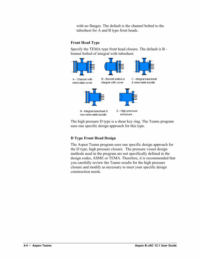
4-4 • Aspen Teams Aspen B-JAC 12.1 User Guide
with no flanges. The default is the channel bolted to the tubesheet for A and B type front heads.
Front Head Type Specify the TEMA type front head closure. The default is B - bonnet bolted of integral with tubesheet.
The high pressure D type is a shear key ring. The Teams program uses one specific design approach for this type.
D Type Front Head Design The Aspen Teams program uses one specific design approach for the D type, high pressure closure. The pressure vessel design methods used in the program are not specifically defined in the design codes, ASME or TEMA. Therefore, it is recommended that you carefully review the Teams results for the high pressure closure and modify as necessary to meet your specific design construction needs.
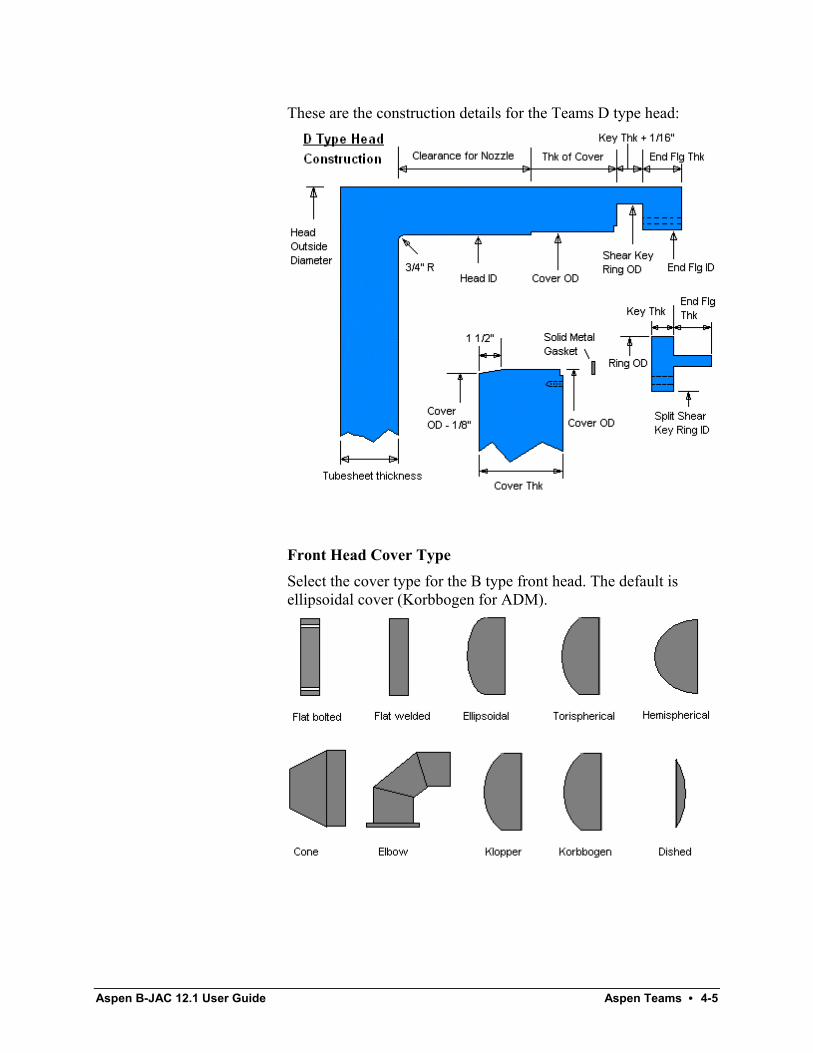
Aspen B-JAC 12.1 User Guide Aspen Teams • 4-5
These are the construction details for the Teams D type head:
Front Head Cover Type Select the cover type for the B type front head. The default is ellipsoidal cover (Korbbogen for ADM).
4-6 • Aspen Teams Aspen B-JAC 12.1 User Guide
Front Head Cylinder Details Sheet Use this sheet to specify these front head cylinder details: • Outside and inside diameters • Thickness • Length • Length for external pressure • Joint efficiency • Girth weld location • Longitudinal weld location angle
If you specify an outside diameter, the program will hold the outside diameter and calculate and inside diameter based upon the calculated required cylinder thickness. If you specify an inside diameter, the program will hold the inside diameter and calculate and an outside diameter based upon the calculated required cylinder thickness.
If a pipe material is specified, cylinders 24 inches and smaller, we recommend that you specify the outside diameter so that a standard pipe wall thickness can be determined.
If check rating an existing design, specify the cylinder outside diameter or inside diameter, thickness, length, length for external pressure, and joint efficiency.
Cover Details Sheet Use this sheet to specify these front head cover details: • Outside and inside diameters • Thickness • Forming tolerance • Joint efficiency • Head ratio • Straight flange length • Depth
If check rating an existing design, specify the cover outside diameter, cover inside diameter, cover thickness, and cover joint efficiency.

Aspen B-JAC 12.1 User Guide Aspen Teams • 4-7
Front Head Flat Heads Sheet If you select a font head type that includes flat heads, use this sheet to specify the relevant details.
Front head flat bolted cover If check rating an existing design, specify the following flat bolted, front head cover information: • Clad thickness • Clad OD (if cladded) • 1st recess depth (from center) • 1st recess diameter • 2nd recess depth (from center) • 2nd recess diameter
Front head flat welded cover If check rating an existing design, specify the following flat welded, front head cover information: • Clad thickness (if cladded) • Flat head weld attachment type • "C" factor in calculation of flat cover
Shell Sheet Use this sheet to specify: • Shell type
This is the shell TEMA type, except type V. • Exchanger (vessel) position
Specify horizontal (default) or vertical position. • Shell outside and inside diameters
If you specify an outside diameter, the program will hold the outside diameter and calculate and inside diameter based upon the calculated required cylinder thickness. If you specify and inside diameter, the program will hold the inside diameter and calculate and an outside diameter based upon the calculated required cylinder thickness. If a pipe material is specified, shells 24 inches and smaller, we recommend that you specify the outside diameter so that a standard pipe wall thickness can be determined.
Shell

4-8 • Aspen Teams Aspen B-JAC 12.1 User Guide
Shell Type These are the shell type choices:
The V type shell, which is not currently part of the TEMA standards, is used for very low shell side pressure drops. It is especially well suited for vacuum condensers and has an advantage over the X shell, in that it can readily have vents at the top of the bundle.
The vapor belt is an enlarged shell over part of the bundle length. It is essentially a cross flow exchanger in this section. The remaining portions of the bundle on each side are then baffled and fitted with vents and drains.
Default: E type (except pool boilers), K type for pool boilers
Shell Cylinder Sheet If check rating an existing design, use this sheet to specify these shell cylinder details: • Cylinder thickness • Cylinder length • Length for external pressure • Cylinder joint efficiency • Girth weld location • Longitudinal weld location angle Note: girth and longitudinal weld locations are not considered in the code calculations.
If external pressure is controlling the shell cylinder design, you can specify shell stiffening rings to reinforce the shell. If details are not provided, the program will select a ring size.

Aspen B-JAC 12.1 User Guide Aspen Teams • 4-9
Kettle Cylinder Sheet If the exchanger has a kettle type shell, use this sheet to specify the kettle cylinder outside or inside diameter.
If you are check rating an existing design, use this sheet to specify these details: • Kettle length • Kettle length for external pressure • Kettle joint efficiency
Kettle Reducer/Weir Sheet If the exchanger has a kettle type shell and you are check rating an existing design, use this sheet to specify these kettle reducer details: • Reducer thickness • Reducer cover joint efficiency • Reducer conical angle
When liquid recirculation is required in a kettle reboiler service, a weir plate is generally specified beyond the U-bends. Use this sheet to specify the following Weir related details: • Weir in kettle option • Weir plate material • Weir thickness • Weir plate outer diameter • Weir height
Teams will add additional required shell length for the weir plate and reservoir.
Vapor Belt Sheet Use this sheet to specify the details for the vapor belt assembly.
The vapor belt acts as a distribution device for the flow into the bundle. The vapor belt may act also as a flange & flued type expansion joint devise

4-10 • Aspen Teams Aspen B-JAC 12.1 User Guide
Rear Head Sheet Use this sheet to specify: • Rear head type
The rear head type selection should be based on service requirements.
• Rear head cover type Select the cover type for the rear head.
• Rear head connected to a cylinder A cylinder is required if a nozzle has been indicated at Zone 8 on the Nozzles sheet of the Nozzles - General input form. The default is the rear head cylinder provided for one-pass exchangers.
• Rear channel/cover bolted to tubesheet Select Yes to have the channel assembly bolted to the tubesheet. Select No to have the head welded to the tubesheet. The default is the channel bolted to the tubesheet for L and M type rear heads.
Rear Head Type The rear head type selection should be based upon service requirements.
The removable tube bundle types - P, S, T, U, and W - provide access to the bundle for cleaning and do not require an expansion joint.
Rear Head

Aspen B-JAC 12.1 User Guide Aspen Teams • 4-11
The fixed tubesheet types - L, M, and N - do no allow access to the bundle but have lower construction costs.
The default is U type for kettle shells; M type for all others.
Rear Head Cover Type Select the cover type for the rear head.
The default is flat bolted for L, N, P, and W types; ellipsoidal for M type; dished for S and T types
Rear Head Cylinder Details Sheet Use this sheet to specify these rear head cylinder details: • Outside and inside diameters • Thickness • Length • Length for external pressure • Joint efficiency • Girth weld location • Longitudinal weld location angle
If you specify an outside diameter, the program will hold the outside diameter and calculate and inside diameter based upon the calculated required cylinder thickness. If you specify and inside diameter, the program will hold the inside diameter and calculate and an outside diameter based upon the calculated required cylinder thickness.

4-12 • Aspen Teams Aspen B-JAC 12.1 User Guide
If a pipe material is specified, cylinder 24 inches and smaller, it is recommended to input the outside diameter so that a standard pipe wall thickness can be determined.
If check rating an existing design, specify the cylinder outside diameter or inside diameter, thickness, length, length for external pressure, and joint efficiency.
Rear Head Cover Details Sheet Use this sheet to specify these rear head cover details: • Outside and inside diameters • Thickness • Forming tolerance • Joint efficiency
If check rating an existing design, specify the rear head cover outside diameter or inside diameter, thickness, and joint efficiency. Depending on the type of cover, other parameters may be required.
Rear Head Flat Heads Sheet If you select a rear head type that includes flat heads, use this sheet to specify the relevant details.
Rear head flat bolted cover If check rating an existing design, specify the following flat bolted, rear head cover information: • Cladding thickness and clad OD (if cladded) • 1st recess depth (from center) • 1st recess diameter • 2nd recess depth (from center) • 2nd recess diameter
Rear head flat welded cover If check rating an existing design, specify the following flat welded, rear head cover information: • Clad thickness (if cladded) • Flat head weld attachment type • "C" factor in calculation of flat cover
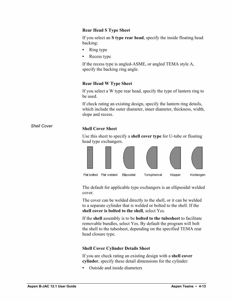
Aspen B-JAC 12.1 User Guide Aspen Teams • 4-13
Rear Head S Type Sheet If you select an S type rear head, specify the inside floating head backing: • Ring type • Recess type
If the recess type is angled-ASME, or angled TEMA style A, specify the backing ring angle.
Rear Head W Type Sheet If you select a W type rear head, specify the type of lantern ring to be used.
If check rating an existing design, specify the lantern ring details, which include the outer diameter, inner diameter, thickness, width, slope and recess.
Shell Cover Sheet Use this sheet to specify a shell cover type for U-tube or floating head type exchangers.
The default for applicable type exchangers is an ellipsoidal welded cover.
The cover can be welded directly to the shell, or it can be welded to a separate cylinder that is welded or bolted to the shell. If the shell cover is bolted to the shell, select Yes.
If the shell assembly is to be bolted to the tubesheet to facilitate removable bundles, select Yes. By default the program will bolt the shell to the tubesheet, depending on the specified TEMA rear head closure type.
Shell Cover Cylinder Details Sheet If you are check rating an existing design with a shell cover cylinder, specify these detail dimensions for the cylinder: • Outside and inside diameters
Shell Cover

4-14 • Aspen Teams Aspen B-JAC 12.1 User Guide
• Thickness • Length • Length for external pressure • Joint efficiency • Girth weld location • Longitudinal weld location
Shell Cover Details Sheet Use this sheet to specify these shell cover details: • Outside and inside diameters • Thickness • Forming tolerance • Joint efficiency
If you are check rating an existing design, specify shell cover outside and inside diameters, the thickness, and joint efficiency.
For a torispherical type shell cover, specify: • Knuckle radius, 5 or diameter • Crown radius, % of diameter • Straight flange length • Cover depth
Shell Cover Flat Heads Sheet If you select a shell cover that is a flat head type, use this sheet to specify the relevant details.
For a flat bolted shell cover, specify: • Cladding thickness and cladding outside diameter (if cladded) • 1st recess depth (from center) • 1st recess diameter • 2nd recess depth (from center) • 2nd recess diameter
For a flat welded shell cover, specify: • Cladding thickness (if cladded) • Flat head weld attachment type • "C" factor in the calculation of the flat cover

Aspen B-JAC 12.1 User Guide Aspen Teams • 4-15
Body Flanges Sheet Use this sheet to specify: • Tube side and shell side flange type
Select the general form of the flange. The categories refer to the shape of the flange as found in ASME Section VIII Division 1, Appendix 2 and other applicable construction codes.
• Tube side and shell side flange design standard For exchanger applications with shell sizes greater that 24" (610mm) diameter, the body flanges are normally custom designed flanges, and the program optimizes to find the best and lowest cost solution for the flange. If you want a pre-designed, standard flange (quite often used for shells 24" and smaller), select the appropriate standard. Note that with a pre-designed flange, flange design calculations will not be provided because they are not required per the code. By default the program optimizes the design based on the applicable code.
• Tube side and shell side confined joints A flange can have different types of faces in relation to the adjoining surface. The default is unconfined (except TEMA R).
Tube Side Flange Type Select the general form of the flange, which may be a ring flange, lap joint flange, or hub flange.
These categories refer to the shape of the flange as found in ASME Section VIII Division 1, Appendix 2 and other applicable construction codes.
Default: ring flange according to figure 2-4(8) of ASME, if attached to a carbon steel cylinder or head; lap joint flange when attached to an alloy cylinder or head.
Shell Side Flange Type Specify the general form of the flange, which may be a ring flange, lap joint flange, or hub flange.
Body Flanges

4-16 • Aspen Teams Aspen B-JAC 12.1 User Guide
These categories refer to the shape of the flange as found in ASME Section VIII Division 1, Appendix 2 or other applicable construction codes.
Default: ring flange according to figure 2-4(8) of ASME, if attached to a carbon steel cylinder or head; lap joint flange when attached to an alloy cylinder or head.
Tube Side/Shell Side Confined Joints A flange can have different types of faces in relation to the adjoining surface. The simplest form is a flat face on which the gasket seats without being restricted radially. A confined joint forms a containment around the gasket.
Default: unconfined (except TEMA R)
Individual Standards Sheet Use this sheet to modify individual standards for • Front head flange at the cover or the tubesheet • Front shell flange • Rear shell flange • Shell cover flange • Rear head flange at the tubesheet or the cover
You can specify a design standard, code type, standard type, standard rating, code facing, standard facing, and confined joint.

Aspen B-JAC 12.1 User Guide Aspen Teams • 4-17
Special Flange Types per ASME Fig. 2.4 Select the code type from the list.
Special Flange Facing Types per ASME Table 2.5.2 Select the code facing from the list.

4-18 • Aspen Teams Aspen B-JAC 12.1 User Guide
Dimensions Sheet Use this sheet to specify these major flange dimensions for all the flanges on the exchanger: • Flange outside and inside diameter, bolt circle, and thickness • Gasket outside diameter, width, and thickness • Bolt diameter and number • Hub length and slope • Weld height
Body flanges can be designed per code rules or selected from standards. You can also enter flange dimensions when executing a rating program run. Designed flanges follow the rules dictated by the specified code. As in the case of nozzle flanges, typical flange types available are ring, lap joint and hub type. The program also automatically investigates the feasibility of optional type flanges calculated as loose or integral.
If check rating an existing flange, you may specify all of the geometry parameters listed of the existing flange or you can specify only partial geometry data. If you are providing partial information, you must, at least, specify all the information listed in one of the following data groups for the flange: • Flange thickness only • Bolt diameter only • Bolt diameter and number of bolts • Gasket diameter, gasket width, gasket thickness, bolt diameter,
and number of bolts • Flange OD, bolt circle, gasket O.D., gasket width, gasket
thickness, bolt diameter, number of bolts, hub length, hub slope, and weld height (if applicable)
• All the flange geometry data listed

Aspen B-JAC 12.1 User Guide Aspen Teams • 4-19
Nubbin/Recess/Gasket Sheet Use this sheet to specify these flange dimensions: • Nubbin width, height, and diameter • Recess depth and diameter • Overlay thickness • Gasket factor m and factor y
If check rating an existing flange, specify the nubbin width, height, and diameter; the recess depth and diameter; the overlay thickness; the gasket m factor and gasket seating stress, when applicable.
Options Sheet Use this sheet to specify these body flange design options: • Design temperature - flanges shell side and flanges tube side
You can set specific design temperatures for the body flanges in lieu of the global design temperatures.
• Include gasket rib area for gasket seating The program will adjust the flange design to include the rib seating area of the gasket (default). This assures that the flange will be able to keep the gasket sealed for operating conditions. You may omit the gasket seating area for the pass partition ribs for the flange calculations.
• Type of bolt You can set the bolt type to US or Metric or Din. The default is the type applicable to the specified code and standards.
• Body flange full bolt load Per Note 2 of ASME Section VIII, paragraph 2-5(e), if additional safety is needed against abuse or where is it is necessary to withstand the full available bolt load, AbSa, specify Yes, for this full bolt load to be considered. The default is standard bolt load, (Am+Ab) * Sa / 2
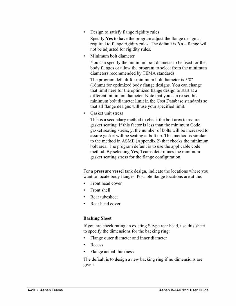
4-20 • Aspen Teams Aspen B-JAC 12.1 User Guide
• Design to satisfy flange rigidity rules Specify Yes to have the program adjust the flange design as required to flange rigidity rules. The default is No � flange will not be adjusted for rigidity rules.
• Minimum bolt diameter You can specify the minimum bolt diameter to be used for the body flanges or allow the program to select from the minimum diameters recommended by TEMA standards. The program default for minimum bolt diameter is 5/8" (16mm) for optimized body flange designs. You can change that limit here for the optimized flange design to start at a different minimum diameter. Note that you can re-set this minimum bolt diameter limit in the Cost Database standards so that all flange designs will use your specified limit.
• Gasket unit stress This is a secondary method to check the bolt area to assure gasket seating. If this factor is less than the minimum Code gasket seating stress, y, the number of bolts will be increased to assure gasket will be seating at bolt up. This method is similar to the method in ASME (Appendix 2) that checks the minimum bolt area. The program default is to use the applicable code method. By selecting Yes, Teams determines the minimum gasket seating stress for the flange configuration.
For a pressure vessel tank design, indicate the locations where you want to locate body flanges. Possible flange locations are at the: • Front head cover • Front shell • Rear tubesheet • Rear head cover
Backing Sheet If you are check rating an existing S type rear head, use this sheet to specify the dimensions for the backing ring: • Flange outer diameter and inner diameter • Recess • Flange actual thickness
The default is to design a new backing ring if no dimensions are given.
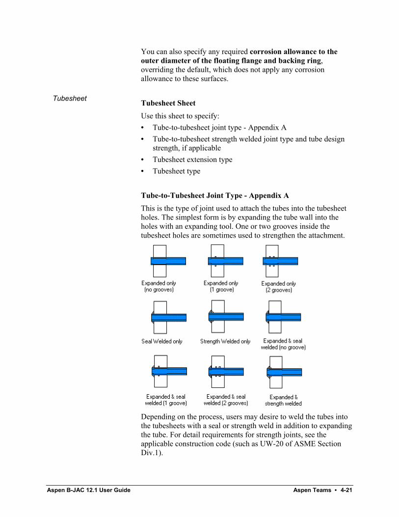
Aspen B-JAC 12.1 User Guide Aspen Teams • 4-21
You can also specify any required corrosion allowance to the outer diameter of the floating flange and backing ring, overriding the default, which does not apply any corrosion allowance to these surfaces.
Tubesheet Sheet Use this sheet to specify: • Tube-to-tubesheet joint type - Appendix A • Tube-to-tubesheet strength welded joint type and tube design
strength, if applicable • Tubesheet extension type • Tubesheet type
Tube-to-Tubesheet Joint Type - Appendix A This is the type of joint used to attach the tubes into the tubesheet holes. The simplest form is by expanding the tube wall into the holes with an expanding tool. One or two grooves inside the tubesheet holes are sometimes used to strengthen the attachment.
Depending on the process, users may desire to weld the tubes into the tubesheets with a seal or strength weld in addition to expanding the tube. For detail requirements for strength joints, see the applicable construction code (such as UW-20 of ASME Section Div.1).
Tubesheet
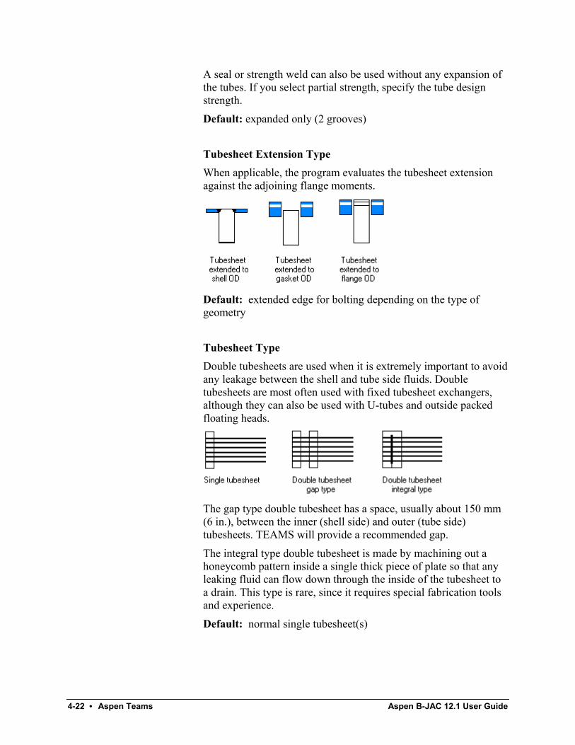
4-22 • Aspen Teams Aspen B-JAC 12.1 User Guide
A seal or strength weld can also be used without any expansion of the tubes. If you select partial strength, specify the tube design strength.
Default: expanded only (2 grooves)
Tubesheet Extension Type When applicable, the program evaluates the tubesheet extension against the adjoining flange moments.
Default: extended edge for bolting depending on the type of geometry
Tubesheet Type Double tubesheets are used when it is extremely important to avoid any leakage between the shell and tube side fluids. Double tubesheets are most often used with fixed tubesheet exchangers, although they can also be used with U-tubes and outside packed floating heads.
The gap type double tubesheet has a space, usually about 150 mm (6 in.), between the inner (shell side) and outer (tube side) tubesheets. TEAMS will provide a recommended gap.
The integral type double tubesheet is made by machining out a honeycomb pattern inside a single thick piece of plate so that any leaking fluid can flow down through the inside of the tubesheet to a drain. This type is rare, since it requires special fabrication tools and experience.
Default: normal single tubesheet(s)

Aspen B-JAC 12.1 User Guide Aspen Teams • 4-23
Tubesheet Types/Welds Sheet Use this sheet to specify the tubesheet attachment type and tube-to-TS weld type - UW-20. • Tubesheet attachment type • Tube-to-TS weld type - UW-20
Specify if the tube to tubesheet welds are to be considered as strength welds per ASME, and specify the af and ag dimensions:
• Fillet weld length, af - Fillet weld leg size for the tube to tubesheet welds.
• Grove weld length, ag - Groove weld leg for the tube to tubesheet welds.
Tubesheet Attachment Type Select a tubesheet attachment type:
The tubesheet attachment defaults to land. This is a recess behind the tubesheet on which the shell rests (typically 3/16" - 5 mm).
Stub end is an extension parallel to the shell axis to which the shell is attached. This method normally requires machining of the stub end with inner and outer radii. For an example, see ASME VIII-1 Fig. UW-13.3(c).
Tubesheet Method/Dimensions Sheet Use this sheet to specify the tubesheet: • Tubesheet design method • Tubesheet/Cylinder optimization • Dimensions
If you specify the tubesheet design temperature on this sheet, the program uses this temperature as the design temperature for the tubesheets in lieu of the general shell/tube side design temperatures specified on the Design Specifications sheet.
4-24 • Aspen Teams Aspen B-JAC 12.1 User Guide
Tubesheet Design Method You can select one of these tubesheet design methods: • TEMA (Eight Edition) • Code (Appendix AA - latest addenda) • The thicker of the two methods • The thinner of the two methods
Code accepts both methods for the tubesheet design. If no method is selected, the program will use the thicker tubesheet of the two methods. Depending on the design conditions and materials of construction, either method may result in a thicker tubesheet.
Generally the ASME method will result in thicker tubesheets, especially, if the tubesheet is welded to the shell or head cylinder. Most users select the thinner tubesheet of the two methods to save cost.
ASME UHX Tubesheet design Select Yes to have Teams apply the new ASME (non-mandatory) heat exchanger standard requirements. Refer to the appendix in ASME Section VIII for additional details for these requirements.
Tubesheet/Cylinder Optimization Select the tubesheet/Cylinder optimization method: • Program
Program calculates the minimum required tubesheet thickness for bending and shear. Then it checks the stresses on the tubes and cylinders (shell or channel) welded to the tubesheet(s). If the stresses on the tubes are exceeded, the program automatically inserts an expansion joint. If the welded shell (i.e., BEM) or welded channel (i.e., NEN) is overstressed at the junction with the tubesheet, the program will issue a warning.
• Increase tubesheet thickness The program increases the tubesheet thickness until all stresses are satisfied, including adjacent components � tubes, shell, channel. This selection results in the thickest tubesheet(s) and thinnest cylinder thickness at the junction.
• Increase adjacent cylinder thickness The program increases the shell thickness (only a small portion adjacent to the tubesheet) and/or the channel thickness (depending of which one is controlling) until the cylinder stresses at the junction with the tubesheet(s) are satisfied. This selection results in the thinnest tubesheet(s) and thickest

Aspen B-JAC 12.1 User Guide Aspen Teams • 4-25
cylinder thickness at the junction. As the cylinder thickness is increased, the tubesheet is reinforced by the thicker cylinder welded to it, and consequently the tubesheet thickness is automatically reduced. If a warning message appears stating that either the shell cylinder or channel cylinder at the tubesheet junction is overstressed, select the increase adjacent cylinder thickness method and rerun the program. This may take a while in some designs. If the resulting cylinder thickness adjacent to the tubesheet is acceptable, the optimization run is finished. If this thickness is not acceptable (too thick), fix this thickness on the Miscellaneous sheet of the Tubesheet form. Then select increase tubesheet thickness and rerun the program. This methodology usually results in a tubesheet thickness less than TEMA with a somewhat thicker cylinder welded to the tubesheet.
Note: The program automatically adjusts all the affected components (adjacent flange geometry) during these optimizations.
Tubesheet Dimensions Specify these front and rear tubesheet dimensions on the Method/Dimensions sheet: • Tubesheet outer diameter and thickness • Front tubesheet partition groove width and rear pass partition
plate groove width • Front tubesheet partition groove depth and rear pass partition
plate groove depth
Tubesheet cladding is typically a layer of alloy material applied to a carbon steel base on the tube-side face of the tubesheet. If cladded, enter the front and rear: • Clad diameter and thickness • Tubesheet cladding material, tube side

4-26 • Aspen Teams Aspen B-JAC 12.1 User Guide
Specify how the cladding is bonded to the tubesheet base material, explosively bonded or loose type. The type of bonding does not affect Code calculations.
If check rating an existing exchanger, enter the tubesheet outer diameter, and width and depth partition groove. If cladded, enter the clad diameter and thickness and tubesheet cladding material.
Recess/Corrosion Allowance Sheet Use this sheet to specify corrosion allowance requirements for the shell side and tube side of the tubesheets. The values entered here override the global corrosion allowances entered for the shell and tube sides on the Design Specifications sheet.
You can specify any reasonable value for corrosion allowance. By default the corrosion Allowance is obtained from the TEMA standards as follows: • For carbon steel TEMA C and , 0.0625" (1.6 mm) • For carbon steel TEMA R, 0.125" (3.2 mm)
Enter zero for no corrosion allowance. There is no default corrosion allowance for materials other than carbon steel.
If check rating an existing exchanger, enter the these recess dimensions for the front/rear tubesheet shell side and tube side: • Recess depth and diameter at ID gasket surface • Recess depth and diameter at OD gasket surface
A backing flange behind the tubesheet is used to avoid transferring the flange moment caused by the adjoining flange to the tubesheet. You can specify the front/rear backing ring flange material. When the tubesheet is made of alloy, the backing ring flange can be made of inexpensive steel material.
Select tubesheet tapped option to have bolt holes tapped in the rear tubesheet instead of bolted through the tubesheet.
Miscellaneous Sheet Use this sheet to specify: • Adjacent tubesheet data
if cylinders attached to the tubesheet are of different materials and design specifications from that of the general cylinders specifications, specify the applicable data here.

Aspen B-JAC 12.1 User Guide Aspen Teams • 4-27
• Differential design pressure if you select Yes, the tubesheets will be designed to a differential design pressure condition between the tube side and shell side of the exchanger. The normal default is to design the tubesheet applying the full tube side pressure for the first case and then the full shell side pressure for the second case and use the greater tubesheet thickness for those two conditions.
• Tube expansion depth ratio You can specify the ratio of the tube expansion length in the tubesheet to the total length of the tubesheet. This will be used for the tube pull out load analysis. The default is TEMA requirements.
• Load transferred from flange to tubesheet The program will automatically transfer the calculated load from the body flange to the tubesheet for the flange extension calculations. For special design considerations, you can specify the load to be used in these calculations.
• Tubesheet allowable stress at design temperature If you wish to specify a special allowable design stress for the tubesheet calculations, enter that value. If not specified, the program will use an allowable design stress per the applicable code.
• Actual differential pressure If you have specified to design the tubesheets using a differential design criteria, the program, by default, uses the design pressures to determine the differential design pressure. You can override the default and specify the differential pressure to be used.
• ASME for thermal cases - use design temperature By default the program uses the mean metal (operating) temperatures for the tubesheet thermal cases. Select this option to have the program use the design temperatures for these cases instead.
• Expansion joint height, hj You can specify the height of the bellows for the expansion joint calculations. If not specified, the program will optimize and select a height.
Double Tubesheet Sheet If double tubesheets have been selected, use this sheet to specify any special temperature and geometry design requirements. For

4-28 • Aspen Teams Aspen B-JAC 12.1 User Guide
any value not provided, the program will select optimum values for design.
Tube Expansion Sheet Use this sheet to specify these tube expansion parameters: • Tube expansion maximum length
The length of the tube expansion into the tubesheet affects the strength of the joint. You can set a maximum tube expansion length limit. By default, Teams uses a tube expansion length as recommended by TEMA or as limited by the tubesheet thickness.
• Tube expansion clearance from shell/channel face Aspen Teams follows TEMA guidelines for the recommended clearance (non-expanded tube sections near the tubesheet faces), unless you specify the clearance needed here.
• Tube expansion depth ratio The ratio of the tube expansion length to the total thickness of the tubesheet. This value is used in the tube pull out load analysis.
Heat Transfer Data Use the following to specify the heat transfer tube parameters: • Heat Transfer Data
If the mean metal temperatures are not known, you can provide shell and tube coefficients, temperatures, and conductivity. From the specified data, Teams estimates the actual mean metal temperatures to use in the tubesheet and expansion joint calculations. If the mean metal temperatures are not provided, Teams uses the specified design temperatures as the mean metal temperatures.
Expansion Joints Sheet Use this sheet to specify if you want an expansion joint for the fixed tubesheet design. Choices are: • Program - program checks and adds expansion joint if
required. This is the default. • Yes -program will add an expansion, even if one is not
required. • No - the unit will be designed without an expansion joint. The
program will notify you if the unit is overstressed.
Expansion Joints

Aspen B-JAC 12.1 User Guide Aspen Teams • 4-29
Select the expansion joint type. Aspen Teams defaults to the flanged and flued type for TEMA exchangers. If a suitable joint cannot be determined, specify the bellows type.
The program uses the specified shell mean metal temperature and the tubes mean metal temperature to design a fixed tubesheet and expansion joint. If not specified, the program will use the design temperatures.
The shell/tubes mean metal temperatures are very important in the correct calculation of the relative expansion of tubes and shell. It is especially important when the program defaults to the design temperatures because these may not be realistic. If the Teams input file is generated by Aspen Hetran, the mean metal temperatures is provided automatically, based upon the TEMA method.
Specify the tubesheet mean metal temperature to be used in the tubesheet design calculations. Normally, the tubesheet metal temperature is very close to the tube metal temperature.
Expansion Joint Type You can select Program or one of the following:
The flange and flued type refers to an expansion joint with two radii. The flanged only type has a radius only at the outer edge. The joint with the shell is a straight angle.
The thin-wall expansion joint is also known as a bellows type and has as an "S" shape. Typical thicknesses are less than 1/8" (3.2 mm) and made of alloy materials. Reinforced bellows requires extra material to be placed on the outside of the joint to provide additional rigidity.
The flanged type is generally the lowest cost expansion joint but is not as flexible as the bellows type.

4-30 • Aspen Teams Aspen B-JAC 12.1 User Guide
Aspen Teams defaults to the flange and flued type for TEMA exchangers. If a suitable joint cannot be determined, specify the bellows type.
The design method for the flanged type is TEMA; for the bellows type, per the specified Code.
Aspen Teams will design thick-wall expansion joints per TEMA Section 5 and thin -wall expansion joints per ASME-VIII-1 App. 26.
Default: flanged and flued type
Geometry Sheet If an expansion joint is required, use this sheet to specify the dimensions.
You can also specify the maximum thickness multiplier and outer diameter multiplier, and whether an outer cylinder is required.
If you are check rating an existing expansion joint, specify the outer cylinder thickness, annular plate thickness, cylinder length, straight flange length, knuckle radius
For additional information, see TEMA 1988 section 5.
Corrosion Allowance/Spring Rate Sheet Use this sheet to specify: • Expansion joint corrosion allowance
The corrosion allowance specified here overrides the global corrosion allowance.
• Number of joints You can specify up to two expansion joints.
• Location one This is the Zone location for the first expansion joint.

Aspen B-JAC 12.1 User Guide Aspen Teams • 4-31
• Location two This is the Zone location for the second expansion joint.
• Spring rate (corroded), Spring rate (new) These are the bellows type expansion joint spring rates for the corroded and new conditions. If not specified, the program will calculate the spring rate.
• Expansion joint cycle life You can specify a required life cycle, or the program will calculate the estimated cycle life.
If you are check rating an existing joint specify the applicable corrosion allowance, number of joints, location of first joint and second joint (if required), spring rates (corroded, new), and the expansion joint life cycle.
Bellows Sheet If check rating an existing bellows type expansion joint, use this sheet to specify the: • Bellows reinforcing material • Number of convolutions • Geometry details
Stress Factors Sheet Use this sheet to specify stress multipliers to adjust the allowable design stresses used in the TEMA expansion joint calculations. If left blank, the program uses allowable stresses recommended by TEMA.

4-32 • Aspen Teams Aspen B-JAC 12.1 User Guide
Tubes Sheet Use this sheet to specify the tube geometry: • Number of tubes: If you do not specify the number of tubes,
the program calculates the maximum number of tubes that will fit in a given exchanger geometry. This number varies not only with the tube diameter, pitch and layout, but also with the type of exchanger (floating head, etc.). The default is program calculated.
• Tube length: Specify the overall tube length for straight tubes. For U-tubes specify the tangent straight length.
• Tube OD: Specify the actual dimensional outside diameter. • Tube wall thickness: The program will check if the tube wall
thickness is adequate to withstand the design pressure, both internal and external. If you enter the average tube wall thickness, determine the minimum tube wall based upon the manufacturing tolerance (generally in the range of 10 to 12%) and verify it is not less than the calculated required thickness for the tubes. For low fin tubes, the tube wall thickness specified will be maintained below the fins.
• Tube type: Plain tubes do not have any enhancing type of surface on them. Fin tubes are classified as integral low-fin types with densities of 16 to 30 fins per inch (630 to 1181 fins per meter). Typical fin heights are 0.015 to 0.040 inches (0.4 to 1 mm). The program requires only the fin density.
• Tube wall specification: Specify the tube wall specification, which appears on the TEMA data sheet. The default is minimum wall. If you specified average wall thickness, see tube wall thickness. The program does not adjust the tube wall thickness based upon this average or minimum wall specification. This option only sets a tubing requirement specification on the data sheet.
• Tube projection from tubesheet: Tube projection from the tubesheet face should be based upon the type of attachment and any customer specification requirements. The default is 1.5 mm or 0.625 in.
• Tubes design temperature: Specify the tube design temperature, which will determine the physical properties used in the code calculations. The default is higher of shell and tube side design temperatures.
• Tubes corrosion allowance: For most design applications no corrosion allowance is applied to the tubes, even if you have specified a general corrosion allowance for the shell and tube sides of the exchanger. Specify the total corrosion (shell side
Tubes/Baffles

Aspen B-JAC 12.1 User Guide Aspen Teams • 4-33
and tube side) allowance required. The default is zero corrosion allowance.
• Tubes allowable design stress at design temperature: If not provided, the program will determine the design stress based upon tube material specified at the design temperature. You may override this calculated design stress by entering it here. The default is the allowable design stress at design temperature based upon material specified.
If you specify fin tubes as the tube type, you must specify the desired fin density.
Fin Tubes If you specify fin tubes as the tube type, then you must specify the desired fin density (the number of fins per inch or per meter depending on the system of measure). Since the possible fin densities are very dependent on the tube material, you should be sure that the desired fin density is commercially available.
The dimensional standards for finned tubes made by Wolverine, High Performance Tube, and Wieland are built into the program. If you choose one of these, the program will automatically supply the corresponding fin height, fin thickness, and ratio of tube outside to inside surface area. If you do not choose one of the standard fin densities, then you must also supply the other fin data which follows in the input.
The standard fin densities, fins/inch, for various materials are: Tube Material Fins/Inch Carbon Steel 19 Stainless Steel 16, 28 Copper 19, 26 Copper-Nickel 90/10 16, 19, 26 Copper-Nickel 70/30 19, 26 Nickel Low Carbon Alloy 201 19 Nickel Alloy 400 (Monel) 28 Nickel Alloy 600 (Inconel) 28 Nickel Alloy 800 28 Hastelloy 30 Titanium 30 Admiralty 19, 26 Aluminum-Brass Alloy 687 19

4-34 • Aspen Teams Aspen B-JAC 12.1 User Guide
Fin height The fin height is the height above the root diameter of the tube.
Fin thickness The fin thickness is the average fin thickness.
Teams Baffles Sheet Use this sheet to specify: • Baffle type, which can be divided into two general categories:
Segmental baffles, which are pieces of plate with holes for the tubes and a segment that has been cut away for a baffle window. Single, double, triple, no tubes in window, and disk & donut are examples of segmental baffles. Grid baffles, which are made from rods or strips of metal that are assembled to provide a grid of openings through which the tubes can pass. The program covers two types of grid baffles - rod baffles and strip baffles.
• Baffle orientation - horizontal, vertical, or rotated - is with respect to a horizontal exchanger. On vertical units the baffle cut will be typically perpendicular to the shell nozzles axes.
• Bundle removal space, the bundle removal space required depends on the specified TEMA type of the exchanger. Bundle removal space is not applicable to fixed tubesheet designs but is needed for removal type bundles, S / T / P / W / U rear head types. The type of front head specified also affects the removal space needed. The A & B front type heads are generally removed before the bundles are removed and therefore, removable clearance for the front heads is not needed.
Teams Baffle Type Baffle types can be divided up into two general categories: • Segmental baffles • Grid baffles
Segmental baffles, the most common type of baffle, are pieces of plate with holes for the tubes and a segment that has been cut away for a baffle window. Single, double, triple, no tubes in window, and disk & donut are examples of segmental baffles, with the single segmental baffle being the type used in a majority of shell and tube heat exchangers.

Aspen B-JAC 12.1 User Guide Aspen Teams • 4-35
The baffles should have at least one row of overlap, and therefore become practical for a 20 mm or 0.75 in. tube in shell diameters of 305 mm (12 in.) or greater for double segmental and 610 (24 in.) or greater for triple segmental baffles. Note: The B-JAC triple segmental baffle is different than the TEMA triple segmental baffle.
Full supports are used in K and X type shells where baffling is not necessary to direct the shell side flow.
No tubes in window is a layout using a single segmental baffle with tubes removed in the baffle windows. This type is used to avoid tube vibration and may be further enhanced with intermediate supports to shorten the unsupported tube span. The standard abbreviation for no tubes in the window is NTIW.
Grid baffles are made from rods or strips of metal that are assembled to provide a grid of openings through which the tubes can pass. The program covers two types of grid baffles - rod baffles and strip baffles.
Rod baffle design is based on the construction and correlations developed by Phillips Petroleum. Rod baffles are limited to a square tube pattern. The rods are usually about 6 mm (0.25 in.) in diameter. The rods are placed between every other tube row and welded to a circular ring. There are four repeating sets where eachbaffle is rotated 90 degrees from the previous baffle.
Strip baffles are normally used with a triangular tube pattern. The strips are usually about 25 mm (1 in.) wide and 3 mm (0.125 in.) thick. The strips are placed between every tube row. Intersecting strips can be notched to fit together or stacked and tack welded. The strips are welded to a circular ring. Strip baffles are also sometimes referred to as nest baffles.
Default: single segmental except X shells; full support for X shell

4-36 • Aspen Teams Aspen B-JAC 12.1 User Guide
Baffle Details Sheet Use this sheet to specify these baffle details: • Baffle cut in percent of vessel diameter: The baffle cut is
based on the percent of shell diameter. Typically 15% to 45%, depending on flow parameters and type of baffle (single vs. double vs. triple segmental or no-tubes-in-window). For double-segmental baffles, the baffle cut is the size of the inner window divided by the shell diameter X 100. For triple-segmental baffles, the baffle cut is the size of the innermost window divided by the shell diameter X 100. For nests or rod baffles, there is no baffle cut (leave blank or zero).
• Baffle number: Number of transverse baffles including full supports when applicable. The number of baffles applies to all transverse baffles and full supports. It should include the full support(s) under the nozzle(s) on a G, H, or J type shell. It should not include the full support at the beginning of the u-bend of a u-tube bundle.
• Baffle spacing: Specify the center-to-center baffle spacing. This number and the number of baffles are complementary. If not entered, the program will determine the inlet and outlet baffle spacing.
• Baffle inlet spacing: Specify the baffle spacing at the inlet nozzle. If not entered, the program will set based upon the center to center spacing and outlet spacing if specified. If the outlet spacing is not specified, the program will set the inlet and outlet spacing the same based upon available tube length.
• Baffle outlet spacing: Specify the baffle spacing at the outlet nozzle. If not entered, the program will set based upon the center to center spacing and the inlet spacing if specified. If the inlet spacing is not specified, the program will set the inlet and outlet the spacing the same based upon available remaining tube length.
• Baffle thickness: Specify the actual thickness of the baffles. The default is TEMA standards.
• Baffle diameter: Specify the actual baffle outside diameter. The default is TEMA standards.
• Unsupported tube span: Normally you allow the program to calculate the unsupported tube span based upon the baffles spacing. If you specify an unsupported tube span, Aspen Teams uses this value in lieu of the program value in the TEMA fixed tubesheet calculations.
• Unsupported tube span Factor k: Enter the unsupported tube span k factor used to determine the Cc variable in the TEMA

Aspen B-JAC 12.1 User Guide Aspen Teams • 4-37
tube compressive stress calculations, if you want to override the program calculated k factor.
Double/Triple Cuts Sheet Use this sheet to specify double baffle and triple segmental cuts. The baffle cut is based on the percent of shell diameter.
For more information on double and triple segmental baffle cuts, see the Appendix.
Tubesheet Layout Sheet Use this sheet to specify: • Tube pattern
The tube pattern is the layout of the tubes in relation to the shell side crossflow direction, which is normal to the baffle cut edge. The default is 30 degrees.
• Tube pitch This is the center-to-center distance between adjacent tubes within the tube pattern. The default is the minimum recommended by TEMA.
• Tube passes Specify the number of tube passes.
• Tube pass layout type This is the layout of the tubes for four or more passes.
• Impingement protection type The purpose of impingement protection is to protect the tubes directly under the inlet nozzle by deflecting the bullet shaped flow of high velocity fluids or the force of entrained droplets.
• Outer tube limit diameter The outer tube limit (OTL) is the diameter of the circle beyond which no portion of a tube will be placed. If you specify an OTL, the program determines the maximum number of tubes that will fit. If no OTL is specified, the program calculates the OTL based upon the specified shell diameter and TEMA standard bundle clearances. By default the program calculates the OTL.
• Layout option You can select to have the program generate a new tube layout for each run (default), or you can select to use an existing layout. For the second option, you must first run Teams to
Tubesheet Layout

4-38 • Aspen Teams Aspen B-JAC 12.1 User Guide
establish a layout and then select the option to use the existing layout for all subsequent runs.
Tube Pass Layout Type There are several possible ways to layout tubes for four or more passes.
Quadrant layout has the advantage of usually (but not always) giving the highest tube count. It is the required layout for all U-tube designs of four or more passes. The tube side nozzles must be offset from the centerline when using quadrant layout. The program automatically avoids quadrant layout for shells with longitudinal baffles and 6, 10, or 14 pass, to avoid having the longitudinal baffle bisect a pass.
Mixed layout has the advantage of keeping the tube side nozzles on the centerline. It often gives a tube count close to quadrant and sometimes exceeds it. The program automatically avoids mixed layout for shells with longitudinal baffles and 4, 8, 12, or 16 passes.
Ribbon layout nearly always gives a layout with fewer tubes than quadrant or mixed layout. It is the layout the program always uses for an odd number of tube passes. It is also the layout preferred by the program for X-type shells. The primary advantage of ribbon layout is the more gradual change in operating temperature of adjacent tubes from top to bottom of the tubesheet. This can be important when there is a large change in temperature on the tube side, which might cause significant thermal stresses in mixed and quadrant layouts.
Default: program will optimize
Impingement Protection Type The purpose of impingement protection is to protect the tubes directly under the inlet nozzle by deflecting the bullet shaped flow of high velocity fluids or the force of entrained droplets. TEMA recommends that inlet impingement protection be installed under the following conditions:

Aspen B-JAC 12.1 User Guide Aspen Teams • 4-39
• when the rho*V² through the inlet nozzle exceeds 2232 kg/(m*s²) or 1500 lb/(ft*s²) for non-corrosive, non-abrasive, single phase fluids
• when the rho*V² through the inlet nozzle exceeds 744 kg/(m*s²) or
• 500 lb/(ft*s²) for corrosive or abrasive liquids • when there is a nominally saturated vapor • when there is a corrosive gas • when there is two phase flow at the inlet
If you choose a plate on the bundle the program automatically removes tubes under the inlet nozzle so that the shell entrance area equals the cross-sectional area of the nozzle. This is approximately equal to removing any tubes within a distance of 1/4 the nozzle diameter under the center of the nozzle. The program default uses a circular impingement plate equal in diameter to the inside diameter of the nozzle, and approximately 3 mm or 1/8 in. thick.
An alternative is to put a plate in a nozzle dome, which means suspending the impingement plate in an enlarged nozzle neck, which may be a dome or a cone.
Details/Pass Partitions Sheet Use this sheet to specify tubesheet layout details and pass partitions details.
You can specify these tubesheet layout details: • Max deviation per pass in percent
The program defaults to 5% maximum deviation per pass when calculating how many tubes can fit in a given pass.
• Degree of symmetry If specified, the program will attempt to put the same number of tubes per pass. If not specified, the program will optimize as many tubes as possible in a given configuration.
• Min U-bend Diameter The program default is 3 times the tube OD.
4-40 • Aspen Teams Aspen B-JAC 12.1 User Guide
You can specify the following detailed information about the pass partitions: • Pass partition lane clearance • Allowable pressure drop across the partition plate • Pass partition corrosion allowance • Front (top) pass partition plate thickness • Front head pass partition rib length and width • Pass partition dimension �a� and pass partition dimension �b�
(TEMA standards).
Tie Rods/Spacers Sheet Use this sheet to specify tie rod and tie rod spacer information.
You can specify the following tie rod information: • Number of tie rods • Diameter and length of the tie rod • Tie rod material
You can specify the following for the information for the tie rod spacers:
Number of spacers Diameter and thickness of the spacer Spacer material
Drawing Sheet Once you have run the Teams program and have mechanical design results, you can interactively make modifications to the tube layout.
Tubes: Tubes can be removed from the layout by clicking on the tube to be removed (tube will be highlighted in red) and then selecting the red X in the menu. If you want to designate a tube as a plugged tube or as a dummy tube, click on the tube (tube will be highlighted in red) and then select the plugged tube icon or dummy tube icon from the menu.
Tie Rods: To remove a tie rod, click on the tie rod (tie rod will be highlighted in red) and then select the red X in the menu. To add a tie rod, select the add a tie rod icon in the menu and then specify the location for the tie rod.
Sealing Strips: To remove a sealing strip, click on the sealing strip (sealing strip will be highlighted in red) and then select the red X

Aspen B-JAC 12.1 User Guide Aspen Teams • 4-41
in the menu. To add a sealing strip, select the add a sealing strip icon in the menu and then specify the location for the sealing strip. Once you have completed your changes to the tube layout, you may want to elect to fix the layout for subsequent Teams runs by selecting the "Use existing layout" option located on the Tubesheet Layout tab.
Shell Side & Tube Side Nozzles Sheets (General) Use the Shell Side sheet and Tube Side sheet to specify the following information: • Nozzle flange design
Select the design. ISO or DIN standards can be referenced. Also an optimized, program calculated flange, may be selected.
• Nozzle elevation above vessel wall Specify the nozzle elevation from vessel centerline to face of nozzle.
• Couplings on nozzles Select number of couplings to be provide in each nozzle. The default is TEMA standards.
• Nozzle flange rating Select the flange rating. The default is to select a flange rating in accordance with the applicable specified code.
• Nozzle flange type Select the nozzle flange type from the list. The default is slip on type.
• Code flange type For code calculated flanges, select a flange type for the optimized nozzle flange.
• Nozzle flange facing Select raised or flat face type. The default is flat face.
• Code flange face type Select facing type for a calculated nozzle flange. The default is a flat facing.
Nozzles & Couplings Sheets Use the Nozzles sheet and Couplings sheet to specify the following information: • Name
Specify the identification of each nozzle for the drawings and text output. Program default starts with the letter A through J.
Nozzles General

4-42 • Aspen Teams Aspen B-JAC 12.1 User Guide
• Description You can provide a description for each nozzle that will appear in the text output.
• Function Select the function of nozzle, such as inlet, outlet, vent, drain. Note that by identifying the inlet nozzles, the program locates impingement plates if one has been specified.
• Type For couplings only, select the coupling design rating.
• Diameter Specify the nominal diameter of nozzle. If actual diameters are specified, the program selects the closest standard nozzle diameter per the applicable code. Program determines actual diameter from the application pipe standards.
• Location Specify a zone location for the nozzle or coupling. This is an approximate location from which the program will calculate the actual dimensional location. Specify a general zone location for the nozzle, zones 1 and 2 for front head nozzles, zones 3 through 7 for shell nozzles, and zones 8 and 9 for rear head nozzles. Nozzles should be located in accordance with the TEMA type of shell that you have selected. Note that the specified zone locations override standard TEMA locations.
• Angle Specify the angle location. For example a nozzle located at the 45 degree points (i.e. 0, 45, 90, 135 �.) will be oriented radially to the cylinder. All other angles result in the nozzle being located hill side on the cylinder.
Domes/Distributor Belts Sheet Use this sheet to specify dome and distributor belt information. In design mode, the program will calculate (or use defaults) for the following dome/distributor information, if program is selected. • Dome type
Select the type of dome: ellipsoidal (default), torispherical, conical, or distributor belt.
• Dome diameter Specify the outside diameter of the dome cylinder.
• Dome location Specify the zone location for the dome at the same location as the location for the attaching nozzle.

Aspen B-JAC 12.1 User Guide Aspen Teams • 4-43
• Dome angle Specify the angle for the dome as the same for the attaching nozzle.
• Dome thickness Specify the thickness for the dome. The default is program calculated.
• Dome cylinder thickness Specify the thickness for the cylinder attached to the dome. The default is program calculated.
• Dome attachment type Select the weld attachment type to vessel. The default is program selected.
• Reinforcing pad If pad is to be provided, specify the OD and thickness. The default is added by program if required.
• Weld leg Weld size for the dome to vessel attachment weld. The default is program calculated.
• Distributor belt type Select type from ASME appendix 9.
• Knuckle radius Specify the knuckle radius for flanged and flued type distributor belt. The default is program selected.
If you are running in the check rating mode, specify the information required, as applicable.
Nozzle Cylinders/Re-Pads Sheet Use this sheet to specify nozzle cylinder and nozzle reinforcing pad details. In design mode, the program calculates (or uses defaults) for the following information. • nozzle cylinder thickness • nozzle reinforcing pad OD • nozzle reinforcing pad thickness • nozzle reinforcing pad parallel limit
In check rating mode, specify the nozzle-related information, as applicable.
Nozzle Details
4-44 • Aspen Teams Aspen B-JAC 12.1 User Guide
Nozzle Projection/Elevation/Distances Sheet Use this sheet to specify the nozzle projection, elevation, and distances details. In design mode, the program calculates (or uses defaults) for the following nozzle detail information: • Type attachment
Select the type of nozzle attachment to the vessel from the list • Weld leg height, Nozzle
Specify the weld leg height at the nozzle attachment to the cylinder at the outside surface.
• Weld leg height, Internal Projection Specify the weld leg height of the nozzle attachment to the vessel cylinder at the nozzle projection into the vessel.
• Weld leg height, Re Pad Specify the weld leg height at the reinforcement pad.
• Projection Specify the projection of the nozzle into the vessel from the inside surface. The program default is having the nozzles flush with the inside vessel surface.
• Elevation Specify the distance the nozzle extends beyond the vessel OD. The elevation above the vessel wall defaults to a minimum of 6" (152 mm). The user can enter values to clear the thickness of insulation, if present.
• Distance from nozzle centerline, Gasket Specify the distance from nozzle center line to from tubesheet gasket face.
• Nozzle distance from nozzle centerline head Specify the distance from nozzle center line to centerline of front head nozzles.
• Offset distance, Nozzle As an alternate to specifying the angle location for an offset nozzle (Nozzles-General form, Nozzles sheet), you can specify the offset distance from the nozzle centerline tot he vessel centerline.
In check rating mode, specify the nozzle-related information, as applicable.

Aspen B-JAC 12.1 User Guide Aspen Teams • 4-45
Nozzle Flanges & Nozzle Clearances Sheets (Details) Use the Nozzle Flanges sheet and the Nozzle Clearances sheet to specify the nozzle flanges details. In design mode, the program calculates (or uses defaults) for the following information: • Nozzle flange standard
The nozzle flanges can be designed or selected from standards. • Nozzle flange type
The nozzle flange types in ASME follow the ANSI B16.5 standard including long weld neck types (thicker necks).
• Nozzle flange rating You can select a flange rating or allow the program to determine the appropriate rating based on materials of construction and the design pressure and temperature of the flanges per applicable standards (ANSI, DIN, or AFNOR). The default is to allow the program to determine flange rating per applicable standards.
• Nozzle face Select the nozzle facing type. The default is flat face.
• Nozzle clearances Specify minimum clearances for nozzles to flanges and tubesheets. The default is one nozzle diameter.
In check rating mode, specify the nozzle-related information, as applicable.
Nozzle Flange Type
The nozzle flange types in ASME follow the ANSI B16.5 standard, including long weld neck types (thicker necks). If you do not want separate reinforcing plates, self-reinforced nozzle styles 'H' and 'S' are also available. Style 'S' provides a

4-46 • Aspen Teams Aspen B-JAC 12.1 User Guide
thicker neck at the junction to the vessel than style 'H' which also provides a thicker neck than a long weld neck.
External Loads Sheet Use this sheet to specify external loads and moments information. In design mode, the program calculates (or uses defaults) for the following nozzle detail information:
In the check rating mode, specify the nozzle-related information, as applicable.
Nozzle external loads: To evaluate external piping loads to WRC-107, enter loads and moments as indicated.
Horizontal Sheet Use this sheet to specify: • Support type - horizontal
The program analyzes the shell stresses caused by supports in both the horizontal (saddles). For saddles the program uses the method developed by L.P.Zick. When this method indicates an over-stressed condition, the program warns the user. Typical locations and angle for saddles are 4 and 6 and 180 degrees. Other angles are only used for stacked exchangers (zero degrees). Calculation methods for supports for stacked exchangers are not yet available.
• Saddle support A location
Horizontal Supports

Aspen B-JAC 12.1 User Guide Aspen Teams • 4-47
Specify general zone (zones 3 or 4) location for the front saddle support.
• Saddle support B location Specify general zone (zones 6 or 7) location for the rear saddle support.
• Saddle support location angle Specify angle location for the saddle supports (180 degrees for bottom supports or 0 degrees for top support with stacked units).
• Distance from face of front tubesheet to bolt hole in support A You can specify the actual dimensional location of the front support from the front tubesheet.
• Distance from face of front tubesheet to bolt hole in support B You can specify the actual dimensional location of the rear support from the front tubesheet
• Distance from bolt hold in support A to nearest stiffening element This will define the nearest shell stiffening element to be considered in the Zick support analysis.
• Distance from bolt hold in support B to nearest stiffening element This will define the nearest shell stiffening element to be considered in the Zick support analysis.
• Load on Saddles You can specify dead weight loads for the Saddle �A� and Saddle �B� supports. Program uses these values in lieu of the calculated loads based on the full weight of the vessel.
Details Sheet Use this sheet to specify your own design for the saddle supports.
Saddle to shell angle of contact
The angle of contact is normally set at 120 degrees.

4-48 • Aspen Teams Aspen B-JAC 12.1 User Guide
Support elevation This is the projection of the saddle support from the vessel centerline.
Wear plate thickness
Plate thickness varies from 0.25 inches up to the thickness of the shell cylinder. Program defaults to no wear plate.
Base plate thickness
The normal thickness ranges from 0.5 inches to 2 inches.
Base plate width Any width is accepted up to the diameter of the shell.
Base plate depth The normal depth is from 4 inches to 12 inches.
Gussets/Bolts Sheet Use this sheet to specify the gussets and bolt hole information for your design.
Gusset thickness Gusset thickness ranges from 0.375 inch
to 1 inch.
Gusset number per support
Ranges from one to four gussets.
Gusset direction Supports opened towards the center of the vessel or outward towards the ends of the vessel.
Bolt holes diameter (dh)
Size ranges from 0.625 inch to 3 inch allowing for 1/8 inch clearance to bolt diameter.
Bolt distance edge to x axis (ce)
Allow a minimum of 2 times the bolt hole size.
Bolt center to center distance (cc)
Any dimension less than the diameter of the vessel.
Bolt slot length (lh) Generally the slot is 2 times the bolt hole diameter.
Bolt quantity Normal ranges from 2 to 8 bolts.

Aspen B-JAC 12.1 User Guide Aspen Teams • 4-49
Stacked Units Sheet Use this sheet to specify the number of stacked exchangers, up to four units.
The detailed drawings include a sketch showing the stacking arrangement for the exchangers. However, you will need to evaluate the vessel support design for base and intermediate supports.
Note that it is possible to input a total weight for the stacked exchangers, and the program will design the base support using this total weight. The program also uses the base support design for the intermediate supports.
Vertical Sheet Currently the program provides a design for vertical lug type supports. The program analyzes the shell stresses caused by vertical (lugs) positions. For vertical lug supports the program will calculate the required lug weld height to avoid over-stressing the shell. Calculations methods for (3) vertical ring supports are not yet available.
Use this sheet to specify the following vertical support information: • Support type- vertical
Specify type of vertical vessel support type. From two to four lug type supports can be specified. The vertical ring type is a single continuous ring around the shell. Calculations for the ring type are not yet available.
• Support location- vertical Specify general zone location (zones 3 through 7) for the support.
• Distance from tubesheet to support Specify the distanced from the tubesheet to the bolt hole in the support.
Vertical Supports

4-50 • Aspen Teams Aspen B-JAC 12.1 User Guide
• Vertical Support angles Specify the angle location for the lug type supports, for example, 180 degrees apart for two lugs and every 45 degrees for 4 lugs.
Lugs Sheet Use this sheet to specify your own design details for the saddle supports:
Wear plate thickness
Plate thickness varies from 0.25 inches up to the thickness of the shell cylinder. Program defaults to no wear plate.
Base plate thickness
Normal thickness ranges from 0.5 inches to 2 inches.
Base plate width Any width is accepted up to the diameter of the shell.
Base plate depth Normal depth is from 4 inches to 12 inches.
Gusset thickness Gusset thickness ranges from 0.375 inch to 1 inch.
Gusset number per support
The number ranges from one to four gussets.
Bolt holes diameter
Diameter size ranges from 0.625 inch to 3 inch, allowing for 1/8 inch clearance to bolt diameter.
Bolt distance edge to x axis
Allow a minimum of 2 times the bolt hole size.
Bolt center to center distance
Specify any dimension less than the diameter of the vessel.
Bolt quantity Quantity ranges from 2 to 8 bolts.
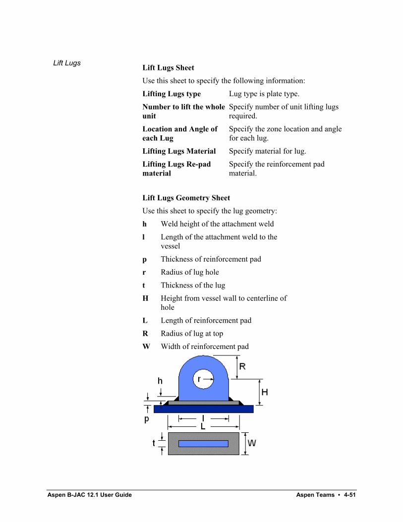
Aspen B-JAC 12.1 User Guide Aspen Teams • 4-51
Lift Lugs Sheet Use this sheet to specify the following information:
Lifting Lugs type Lug type is plate type.
Number to lift the whole unit
Specify number of unit lifting lugs required.
Location and Angle of each Lug
Specify the zone location and angle for each lug.
Lifting Lugs Material Specify material for lug.
Lifting Lugs Re-pad material
Specify the reinforcement pad material.
Lift Lugs Geometry Sheet Use this sheet to specify the lug geometry:
h Weld height of the attachment weld
l Length of the attachment weld to the vessel
p Thickness of reinforcement pad
r Radius of lug hole
t Thickness of the lug
H Height from vessel wall to centerline of hole
L Length of reinforcement pad
R Radius of lug at top
W Width of reinforcement pad
Lift Lugs

4-52 • Aspen Teams Aspen B-JAC 12.1 User Guide
Use this sheet to specify materials for required components. You can use the generic material types such as carbon steel (default), and the program will assign actual default material specifications depending on the product form.
For carbon steel plate, a material specification of SA-516-70 is used for an ASME design. Appropriate specifications are selected for other design construction codes.
To search for a specific material specification, click the Search Databank button. Type the first few characters to search for a material in the databank. Click the Advanced tab to view additional detailed information about the materials in the database.
The Advanced search mode is especially useful to view special ASME material notes. ASME, per the 2002 addendum, allows higher secondary stress limits if (a) the allowable stress for the material is not governed by time-dependent properties as stated in the notes, (b) the ratio of minimum yield to minimum tensile, at room temperature, is less than 0.7, (c) the yield strength at temperature is available from Table Y-1of Section II, Part D.
You can use the DefMats utility to change the default materials.
Use this sheet to specify that all carbon steel materials be normalized per Fig. UCS-66. The program default is to normalize materials when required by the applicable design code.
Use this sheet to specify nozzle materials for required components. The materials specified here apply globally. You can use the generic material types such as "carbon steel" which the program will assign an actual default material specifications depending on the product form. For carbon steel pipe material, a material specification of SA-106-B will be used for an ASME design. Appropriate specifications will be selected for other design construction codes.
To search for a specific material specification, click the Search Databank button. Type the first few characters to search for a material in the databank.
You can use the DefMats utility to change the default materials.
Default: carbon steel
Use this sheet to specify materials for specific nozzles. Any materials specified on this sheet override global settings.
Identify each nozzle for the drawings and text output. The program default starts with the letter A through H. For each nozzle specify:
Materials Material Specifications Sheet
Normalized Materials Sheet
Nozzle Materials Sheet
Nozzle Individual Materials Sheet

Aspen B-JAC 12.1 User Guide Aspen Teams • 4-53
• The nominal pipe size for the diameter. If actual diameters are specified, the program selects the closest standard nozzle diameter per the applicable code. Program determines the actual diameter from the application pipe standards.
• Generic or actual material specification for the cylinder material, nozzle reinforcing pad material, flange, gasket, and bolting. If not specified, the program sets the materials to the default, carbon steel.
You can use the generic material types such as "carbon steel" and the program will assign actual default material specifications depending on the product form. For carbon steel pipe, a material specification of SA-106-B will be used for an ASME design. Appropriate specifications will be selected for other design construction codes.
To search for a specific material specification, click the Search Databank button. Type the first few characters to search for a material in the databank.
You can use the DefMats utility to change the default materials.
Use this sheet to specify the dome and distributor belt formed and cylinder materials and dome reinforcement material. Enter the material in the same order as the nozzles on the domes.
To search for a specific material specification, click the Search Databank button. Type the first few characters to search for a material in the databank.
Use this sheet to specify the shell side and tube side couplings material.
To search for a specific material specification, click the Search Databank button. Type the first few characters to search for a material in the databank.
Use this sheet to specify the external nozzle attachments loads, and they will be analyzed per the Welding Research Council Bulletin, WRC-107. If the nozzle loads are not known but you need the allowable loads based upon your final design, select the Heat Exchange Institute, HEI, method for external nozzle loads and the allowable loads will be calculated.
Dome/DB Materials Sheet
Couplings Materials Sheet
Program Options External Loads/Code Cases Sheet

4-54 • Aspen Teams Aspen B-JAC 12.1 User Guide
Use this sheet to specify the following wind load information: • Vessel effective length and diameter • Velocity pressure exposure coefficient • Topographic factor, Kzt • Importance Factor • Basic wind speed • Gust response factor • Force coefficient • Moment arm
Wind loads are analyzed per ANSI/ASCE 7-95. The default is 160 km/hr (100 mph) wind load
To apply the wind loads to the supports, click the Seismic Loads tab, and select Yes to Apply wind and seismic loads to supports.
Use this sheet to specify the following seismic load information: • Seismic effective vessel length/height • Seismic zone coefficient, Cv • Seismic building period coefficient, CT • Seismic response modification factor, R • Seismic loads are evaluated per ANSI/ASCE 7-95. The default
is zone 1.
To apply wind and seismic loads to vessel supports analysis, select Yes. By default external loads not applied to supports.
Use this sheet to specify exchanger weights. The weights specified here: • Override the program calculated weights • Are used for the vessel support analysis • Appear on the drawings
The support analysis applies one half of the full weight to each support. If support loads have been specified in the vessel support sections, those loads override what is specified here.
If weights for accessories or attachments (interconnecting shell and tube side piping) are specified, they are used in the vessel support stress analysis.
When Insulation is required, the weight of the insulation is added to the total weight of the unit. If insulation is required but you did not specify the details for the insulation, Teams sets the thickness to 2.5" with a density of 8 Lb/ft3. If insulation thickness is
Wind Loads Sheet
Seismic Loads Sheet
Weights Sheet

Aspen B-JAC 12.1 User Guide Aspen Teams • 4-55
specified, Teams checks and adjusts the nozzle projections to clear the insulation. The default is set to "no" insulation.
Shell side and tube side fluid densities are used for the determination of the liquid weight inside the exchanger. If no densities are specified, the density of water is used for weight calculations.
Use the Drawings sheet to select the drawings to be generated when the program runs. You can also specify a title for the drawing number.
If the vessel is being designed to CODAP or AD code, use the sheets of the CODAP and AD Codes form to define the necessary construction categories, safety factors, and design factors.
Using the Change Codes Form Use the Aspen Teams Change Codes form to specify change codes with the associated values.
The format for change code entries is: CODE=value
Change codes are processed after all of the other input and override any previously set value. For instance, if you specify the tube outside diameter as 20 mm in the regular input screens, then enter the change code TODX=25, the 25 will override the 20. If you enter the same change code more than once, the last value will prevail.
Another good use of the change code screen is to "chain" to another file containing only change codes. This is especially convenient if you have a line of standard designs, which you want to use after you have found a similar solution in design mode.
To do this, use the FILE= change code, followed by the name of the file containing the other change codes. The other file must also have a .BJI filetype. You can create this change code file with a standard edit program.
For example, the entry FILE=S-610-2 would point to a file named S-610-2.BJI, which might contain the following data:
SODX=610,TLNG=5000,TNUM=458,TPAS=2,BSPA=690,TODX=20,TPAT=1
These are the change codes that are available in the Aspen Teams program.
Drawings
CODAP and AD Codes
Change Codes

4-56 • Aspen Teams Aspen B-JAC 12.1 User Guide
General Change Codes These are the general change codes that are available in the Teams program:
Code Description bttk baffle thickness cfac "C" factor in calculation of flat covers coan conical head angle (must be less than or equal to 30 degrees) code code requirement: 1=ASME, 2=CODAP, 3=AD/DIN elra radius of turn for 90 degree elbow fcgw front head cylinder girth butt welds present: 0=no, 1=yes fhct front head flat removable cover thickness file specify the name of a file which contains change codes jess joint efficiency for shell side cylinders for nozzle repad calcs jets joint efficiency for tube side cylinders for nozzle repad calcs lang language for input and output: 1=English, 2=French, 3=Spanish, 4=German, 5=Italian meas system of measure: 1=U.S., 2=SI, 3=metric nodr no drawings in TEAMS summary output: 0, 1=yes, 2=no otlm outer tube limit rblf/rblr total length of pass partition ribs in front/rear head srmt/stf1 stiffening ring material / number of stiffening rings rbwf effective width of pass partition ribs in front head rbwr effective width of pass partition ribs in rear head rcgw rear head cylinder girth butt welds present: 0=no, 1=yes rhct rear head flat removable cover thickness scgw shell cover cylinder girth butt welds present: 0=no, 1=yes scat CODAP construction category shell side: 1=A, 2=B, 3=C, 4=D shgw shell girth butt welds present: 0=no, 1=yes shje shell joint efficiency (ASME) sjef CODAP joint efficiency on shell side (0.85 or 1) sstp shell side test pressure ssto shell side tolerance for plate suts tubesheet considered supported: 0=program, 1=yes, 2=no tcat CODAP construction category tube side: 1=A, 2=B, 3=C, 4=D tjef CODAP joint efficiency on tube side (0.85 or 1) tkmn determines if input thickness of pipe is: 0=nominal, 1=minimum tsto tube side tolerance for plate tstp tube side test pressure tupr distance tubes project from tubesheet weir option to eliminate weir in kettle (-1=no weir) heat carbon steel material normalized/tempered: 0=no, 1=yes

Aspen B-JAC 12.1 User Guide Aspen Teams • 4-57
Cylinders & Covers Change Codes These are the cylinders and covers change codes that are available in the Teams program:
Front Head Rear Head cover cyl cover cyl thickness fcot= fcyt= rcot= rcyt= outside diameter fcod= fcyd= rcyd= rcod= length (+) fcyl= rcyl= ext.press.length eln2= eln3= ellip head ratio fcer= rcer= toris head dish r.* fcdr= rcdr= toris head k. rad.* fckr= rckr= over "hub" length fhlg= rhlg=
Shell Shell Cover cyl cyl cover thickness shth= scyt= scot= outside diameter scyd= sccd= scod= length (+) scyl= sccl= ext.press.length (&) eln2= eln4= ellip head ratio scer= toris head dish r.* scdr= toris head k. rad.* sckr= cover "hub" length sclg=
(+)=flange/ts face-to-face or weld *=in percent of head diameter. (&)=eln1 and stf1 should be issued together stf1=number of stiff.rings
Eccentric
Kettle Vapor Distr Belt A Distr Belt B
Redcr Cyl Belt Cyl Ann. Ring
Cyl Ann. Ring
thickness erth= keth= vbth= � � � � outside dia
� keod= vbod= � � � �
material ermt= kemt= � � � � � id/length � keid/
kcyl � � � � �

4-58 • Aspen Teams Aspen B-JAC 12.1 User Guide
Nozzles Change Codes These are the nozzles change codes that are available in the Teams program.
Note that nozzle NZ*A items are for the first nozzle listed in the input, NZ*B changes are for the second nozzle, etc.
Nozzle Nozzle Dome Cyl Reinf
Pad Redcr Cyl Reinf
Pad thickness nzta-j zrta-j nnta-j ncta-j nrta-j outside dia
� zrda-j � � nrda-j
parallel limit
� nzpa-j � � �
Code Description nzxa thru nzxj distance nozzle extends beyond inner surface of vessel fnfa thru fnfj BJAC facing type for nozzle flange (ASME 2-5-2)
(value=1 to 9) wnfa thru wnfj width of nubbin for nozzle flange (ASME table 2-5-2) nwld increase nozzle to vessel weld leg to eliminate pad:
0=yes, 1=no nplm percent parallel limit for shell nozzle adjacent to
tubesheet (0=100%) nfct clearance between tube nozzle flange and back side of
flange (0=0.5") nrtp provide 100% metal replacement in pad:
0=no, 1=uncorroded, 2=corroded rpmt minimum reinforcing pad thickness nrcl clearance between reinf. pad weld and back of
flange/tubesheet (0=2") nccl clearance between nozzle cyl. weld and back of
flange/tubesheet (0=2") nfcs clearance between shell nozzle flange & front side of
tubesheet (0=0.5")

Aspen B-JAC 12.1 User Guide Aspen Teams • 4-59
Body Flanges Change Codes These are the body flanges change codes that are available in the Teams program:
Front Head Rear Head
Cover at TbSh
at TbSh
Cover
thickness ffct= fftt= rftt= rfct= min bolt dia fcmb= ftmb= rtmb= rcmb= facing type fbfa= fbfb= fbff= fbfg= nubbin width wbfa= wbfb= wbff= wbfg= confined joint(**)
fccj= ftcj= rtcj= rccj=
gasket width gawa= gawb= gawf= gawg= weld height fwla= fwlb= fwlf= fwlg=
Shell Front Rear Cover thickness fsft= rsft= scft= min bolt dia � � scmb= facing type fbfc= fbfd fbfe= nubbin width wbfc= wbfd= wbfe= confined joint(**)
fscj= �- sccj=
gasket width gawc= gawd= gawe= weld height fwlc= fwld= fwle=
**=(0=no, 1=yes) fbft= front backing ring flange thickness rbft= rear backing ring flange thickness bolt= bolt type: 1=u.s., 2=metric shnk= DIN bolt type: 1=waisted-shank, 2=rigid sfdt= design temperature for shell side body flanges and bolting tfdt= design temperature for tube side body flanges and bolting

4-60 • Aspen Teams Aspen B-JAC 12.1 User Guide
Floating Head Flange Change Codes These are the floating head flange change codes that are available in the Teams program:
Code Description fhft floating head - flange thickness (recess not included) fhid floating head - flange inside diameter fhdi floating head - dish inside crown radius fhdt floating head - dish (or head) thickness fhhr floating head - dish lever arm(+ toward tube side/- toward
shell side) fhmb floating head - minimum bolt outside diameter fhbf floating head - backing ring flange thickness (recess not
included) cifh floating head - corrosion on the shell side of floating cover fhtd floating head - design temperature rtcj confined joint for rear head gasket at tubesheet: 0=no, 1=yes fhnu bjac facing type for inside flt. head flange (ASME 2-5-2)
(value=1 to 9) fhwi width of nubbin for inside float. head flange (ASME table 2-
5-2) FHFL or BFLF
floating head - flange rating (FHFL or BFLF=1 for rating)
BRRE IFH "S" type backing ring recess: 0=program, 1=none, 2=std., 3=angled
Tubesheets & Expansion Joint Change Codes These are the tubesheets and expansion joint change codes that are available in the Teams program:
Code Description conv number of convolutions cycl minimum expansion joint cycle life (TEMA default=2000
cycles) diff differential design pressure: 0=no, 1=yes difp actual diff. pressure ejbe bellows: 1=unreinforced, 2=reinforced ejca expansion joint corrosion all ejfa expansion joint straight flange - inner cylinder (TEMA
fig. rcb-8.21) **
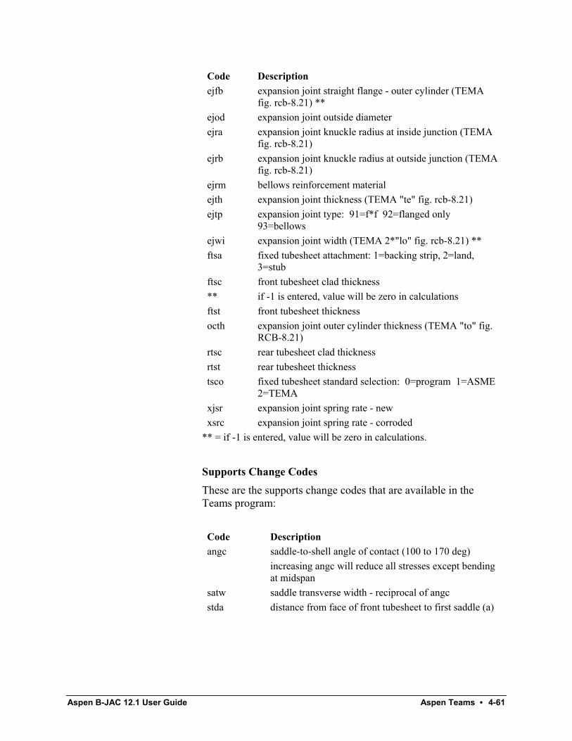
Aspen B-JAC 12.1 User Guide Aspen Teams • 4-61
Code Description ejfb expansion joint straight flange - outer cylinder (TEMA
fig. rcb-8.21) ** ejod expansion joint outside diameter ejra expansion joint knuckle radius at inside junction (TEMA
fig. rcb-8.21) ejrb expansion joint knuckle radius at outside junction (TEMA
fig. rcb-8.21) ejrm bellows reinforcement material ejth expansion joint thickness (TEMA "te" fig. rcb-8.21) ejtp expansion joint type: 91=f*f 92=flanged only
93=bellows ejwi expansion joint width (TEMA 2*"lo" fig. rcb-8.21) ** ftsa fixed tubesheet attachment: 1=backing strip, 2=land,
3=stub ftsc front tubesheet clad thickness ** if -1 is entered, value will be zero in calculations ftst front tubesheet thickness octh expansion joint outer cylinder thickness (TEMA "to" fig.
RCB-8.21) rtsc rear tubesheet clad thickness rtst rear tubesheet thickness tsco fixed tubesheet standard selection: 0=program 1=ASME
2=TEMA xjsr expansion joint spring rate - new xsrc expansion joint spring rate - corroded
** = if -1 is entered, value will be zero in calculations.
Supports Change Codes These are the supports change codes that are available in the Teams program:
Code Description angc saddle-to-shell angle of contact (100 to 170 deg)
increasing angc will reduce all stresses except bending at midspan
satw saddle transverse width - reciprocal of angc stda distance from face of front tubesheet to first saddle (a)
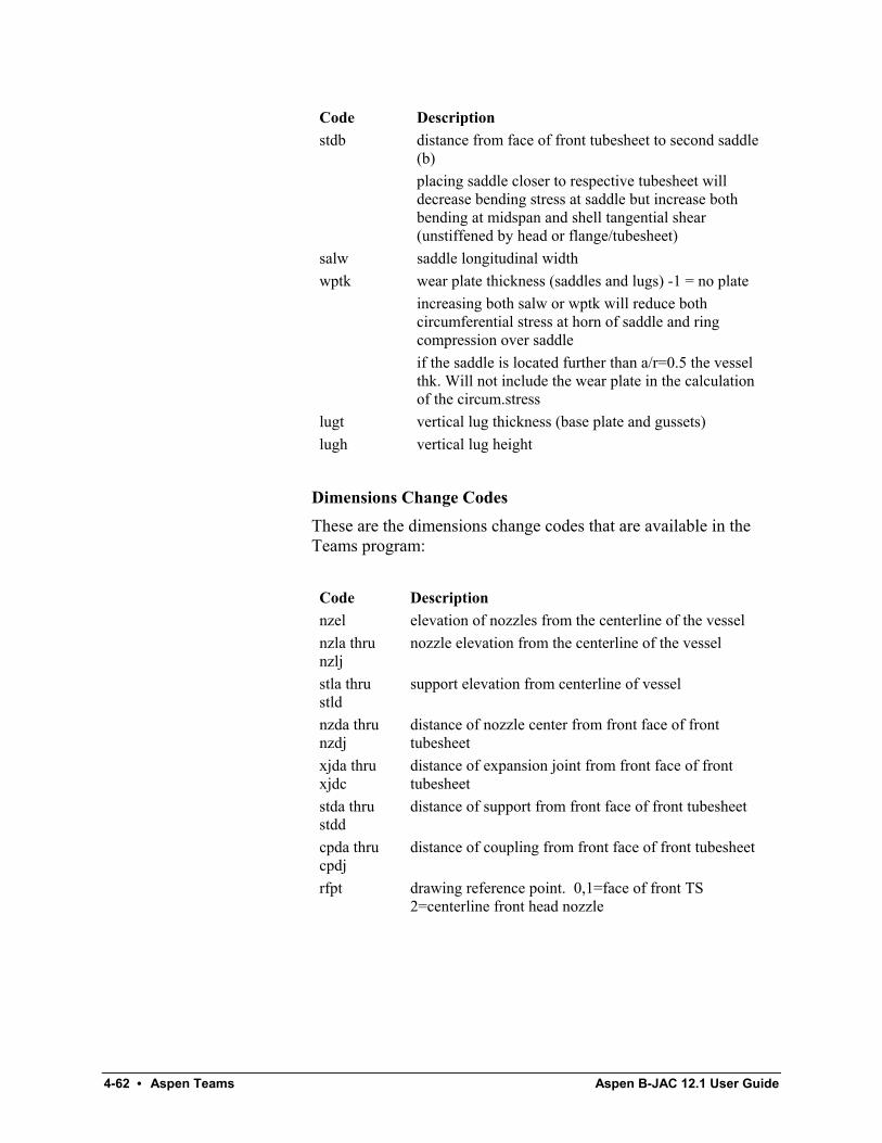
4-62 • Aspen Teams Aspen B-JAC 12.1 User Guide
Code Description stdb distance from face of front tubesheet to second saddle
(b) placing saddle closer to respective tubesheet will decrease bending stress at saddle but increase both bending at midspan and shell tangential shear (unstiffened by head or flange/tubesheet)
salw saddle longitudinal width wptk wear plate thickness (saddles and lugs) -1 = no plate
increasing both salw or wptk will reduce both circumferential stress at horn of saddle and ring compression over saddle if the saddle is located further than a/r=0.5 the vessel thk. Will not include the wear plate in the calculation of the circum.stress
lugt vertical lug thickness (base plate and gussets) lugh vertical lug height
Dimensions Change Codes These are the dimensions change codes that are available in the Teams program:
Code Description nzel elevation of nozzles from the centerline of the vessel nzla thru nzlj
nozzle elevation from the centerline of the vessel
stla thru stld
support elevation from centerline of vessel
nzda thru nzdj
distance of nozzle center from front face of front tubesheet
xjda thru xjdc
distance of expansion joint from front face of front tubesheet
stda thru stdd
distance of support from front face of front tubesheet
cpda thru cpdj
distance of coupling from front face of front tubesheet
rfpt drawing reference point. 0,1=face of front TS 2=centerline front head nozzle

Aspen B-JAC 12.1 User Guide Aspen Teams • 4-63
Teams Results The reported Results are divided into six sections: • Input Summary • Design Summary • Vessel Dimensions • Price • Drawings • Code Calculations
The Input Summary contains three sections: • Basic Data/ Fittings/Flanges • Cylinders/Covers/Tubesheets • Materials/Lift Lugs/Partitions
This part of the input file summary includes information on: • Description/Codes and Standards • Design Specifications • Geometry • Tubesheet/Tubes • Baffles/Tube Layout • Supports -Horizontal/Vertical • Nozzles • Nozzle Cyl/Re-pads • Flanges • Flange Misc.
This part of the input file summary provides the detailed input information on: • Cylinders • Front Head Details • Rear Head Details • Front Head Cover • Front Head Cover Details • Rear Head Cover • Rear Head Cover Details
Input Summary
Basic Data/Fittings/Flanges
Cylinders/Covers/ Tubesheets Details

4-64 • Aspen Teams Aspen B-JAC 12.1 User Guide
• Shell Cylinder • Tubesheets Details • Expansion Joint Details • Shell Cover
This part of the input file summary includes information on: • Main Materials • Nozzle Global Materials • Nozzle Specific Materials • Domes/Coupling Materials • Lift Lug Details • Pass Partitions • Tie Rods and Spacers • Nozzle Clearances
The Design Summary contains five sections: • Warnings & Messages • Design Specifications/Materials • Overall Dimensions/Fitting Locations • MDMT/MAWP/Test Pressure
Aspen B-JAC provides an extensive system of warnings and messages to help the designer of heat exchanger design. Messages are divided into five types. There are several hundred messages built into the program. Those messages requiring further explanation are described here.
Warning Messages: These are conditions, which may be problems, however the program will continue.
Error Messages: Conditions which do not allow the program to continue.
Limit Messages: Conditions which go beyond the scope of the program.
Notes: Special conditions which you should be aware of.
Suggestions: Recommendations on how to improve the design.
This is intended to be a concise summary of the design requirements, including calculated design information such as weights and nozzle flange ratings. The codes in effect are clearly shown indicating applicable date of issue.
Materials/Lift Lugs/Partitions
Design Summary
Warnings & Messages
Design Specifications

Aspen B-JAC 12.1 User Guide Aspen Teams • 4-65
Provides a summary of materials used in the design for all major components. For example:
Component Material Name Shell Cylinder SA-516 Gr 70 Steel Plt Front Head Cylinder SA-516 Gr 70 Steel Plt Rear Head Cylinder SA-516 Gr 70 Steel Plt Front Head Cover SA-516 Gr 70 Steel Plt Rear Head Cover SA-516 Gr 70 Steel Plt Front Tubesheet SA-516 Gr 70 Steel Plt Rear Tubesheet SA-516 Gr 70 Steel Plt Front Head Flange At TS SA-516 Gr 70 Steel Plt Rear Head Flange At TS SA-516 Gr 70 Steel Plt Front Head Flange At Cov SA-516 Gr 70 Steel Plt Front Head Gasket At TS Flt Metal Jkt Asbestos Soft Steel Rear Head Gasket At TS Flt Metal Jkt Asbestos Soft Steel Front Head Gasket At Cov Flt Metal Jkt Asbestos Soft Steel Tubes SA-214 Wld C Steel Tube Baffles SA-285 Gr C Steel Plt Tie Rods SA-36 Bar Spacers SA-214 Wld C Steel Tube Shell Support A SA-285 Gr C Steel Plt Shell Support B SA-285 Gr C Steel Plt Nozzle A SA-106 Gr B Sml Steel Pipe Nozzle B SA-106 Gr B Sml Steel Pipe Nozzle C SA-106 Gr B Sml Steel Pipe Nozzle D SA-106 Gr B Sml Steel Pipe Nozzle Flange A SA-105 Carbon Steel Forg Nozzle Flange B SA-105 Carbon Steel Forg Nozzle Flange C SA-105 Carbon Steel Forg Nozzle Flange D SA-105 Carbon Steel Forg Nozzle Reinforcement A SA-516 Gr 70 Steel Plt Nozzle Reinforcement B SA-516 Gr 70 Steel Plt Nozzle Reinforcement C SA-516 Gr 70 Steel Plt Nozzle Reinforcement D SA-516 Gr 70 Steel Plt Front Hd Bolting At TS SA-193 B7 Steel Blt Rear Hd Bolting At TS SA-193 B7 Steel Blt Front Hd Bolting At Cov SA-193 B7 Steel Blt Expansion Joint SA-516 Gr 70 Steel Plt Nozzle Flange Bolting A SA-193 B7 Steel Blt
Materials of Construction

4-66 • Aspen Teams Aspen B-JAC 12.1 User Guide
Component Material Name Nozzle Flange Bolting B SA-193 B7 Steel Blt Nozzle Flange Bolting C SA-193 B7 Steel Blt Nozzle Flange Bolting D SA-193 B7 Steel Blt Nozzle Flg Gasket A Flt Metal Jkt Asbestos Soft Steel Nozzle Flg Gasket B Flt Metal Jkt Asbestos Soft Steel Nozzle Flg Gasket C Flt Metal Jkt Asbestos Soft Steel Nozzle Flg Gasket D Flt Metal Jkt Asbestos Soft Steel Shell Side Nozzle Cplgs SA-105 C Steel Coupl Tube Side Nozzle Cplgs SA-105 C Steel Coupl
Overall dimensions are calculated as well as intermediate component lengths. These dimensions will also be shown on some of the TEAMS drawings, such as the setting plan and sectional drawing.
The dimensions shown are: • Overall front head assembly • Front Tubesheet • Tubesheet thickness • Tube side recess • Shell side recess • Welding stub end(s) • Cladding Thickness • Shell • Rear Tubesheet • Tubesheet thickness • Tube side recess • Shell side recess • Welding stub end(s) • Cladding Thickness • Overall rear head assembly • Overall shell cover assembly • Unit overall length
All fittings are located from two reference points: distance from the front tubesheet and distance from the front head nozzle. These dimensions will also appear on Aspen TEAMS setting plan drawings.
Overall Dimensions
Fitting Locations

Aspen B-JAC 12.1 User Guide Aspen Teams • 4-67
If any nozzles are offset from the vessel centerline, the amount of the offset will also be indicated.
A general center of gravity is calculated based on each component weight. This reference point can be used when preparing for vessel installation and for proper anchoring during movement.
Minimum Design Metal Temperatures are set based upon the lowest operating temperature the pressure vessel will encounter. Material specifications, impacting testing, and PWHT should be selected that will meet the MDMT requirements per the applicable design construction code.
The program will examine each component separately and calculate its minimum design metal temperature without having to impact test the material. An "*" indicates the controlling component (the one with the highest temperature).
By changing material specifications or testing the component the user can lower the minimum design metal temperature to a desired value.
The ASME Code has many rules on this subject (such as those presented in UG-20(f)) so it is recommended to use additional judgment and experience when deciding on the minimum design metal temperature for a vessel.
The Maximum Allowable Working Pressure is the maximum pressure that the vessel may encounter and not have any component's pressure stress exceed the allowable design stress value per applicable design code.
The program will calculate the maximum allowable working pressure (MAWP) for each component of the vessel. The one with the lowest pressure will be selected as the controlling component and marked with a "*" for the shell side and a "+" for the tube side.
Two sets of pressures are selected: • One for design conditions (corroded at design temperature) • One for "new and cold" conditions (uncorroded at ambient
temperature)
If you want to redesign the equipment using the MAWP, you should change the input data to rating mode. In some cases when the tubesheet controls the MAWP, it will not be possible to design the equipment using the MAWP, because the tubesheet calculation may yield a new MAWP. This occurs because the program uses
Center of Gravity
MDMT
Controlling Component
MAWP
Controlling Component
4-68 • Aspen Teams Aspen B-JAC 12.1 User Guide
the ASME design method, which is dependent not only on the tubesheet geometry but also on the shell and channel geometries as well as different operating cases, such as thermal stresses only, pressure and thermal stresses concurrently, etc. As the design pressure changes, other parameters may control the overall MAWP resulting in a different number.
The program per the applicable design construction code calculates test pressures for the unit.
Post weld heat treatment is performed if required by the applicable design code or as specified by the user in the input.
The Vessel Dimensions Section is subdivided into six sections: • Cylinders & Covers • Nozzles/Nozzle Flanges • Flanges • Tubesheets/Tube Details • Expansion Joint • Supports/Lift Lugs/Wind & Seismic Loads
This section reports the following calculated design dimensions: • Thickness
Cylinders and covers are shown with actual thicknesses selected as well as calculated minimum required thicknesses for both internal as well as external pressure. If a TEMA standard was selected, the program also displays the minimum TEMA thickness based on materials of construction, the TEMA class and the vessel diameter.
• Radiography Code rules are followed for the three typical radiography options: no radiography, spot and full. The program displays the value for the joint efficiency used in the design formulas. In many cases, the program automatically increases the radiography required based on the component calculated thickness per applicable code rules.
• External Pressure The external pressure summary provides limits of design for pressure, thickness and length. You can clearly identify which standard controls the actual thickness selected. If reinforcement rings are required for the shell cylinder, the maximum length is shown for ring placement.
Test Pressure
PWHT
Vessel Dimensions
Cylinders & Covers

Aspen B-JAC 12.1 User Guide Aspen Teams • 4-69
• Kettle Cylinder/Distributor Belt Thickness Cylinders and covers are shown with actual thicknesses selected as well as calculated minimum required thicknesses for both internal as well as external pressure. If a TEMA standard was selected, the program also displays the minimum TEMA thickness based on materials of construction, the TEMA class and the vessel diameter.
• Kettle Cylinder/Distributor Belt Radiography Code rules are followed for the three typical radiography options: no radiography, spot and full. The program displays the value for the joint efficiency used in the design formulas. In many cases, the program automatically increases the radiography required based on the component calculated thickness per applicable code rules.
• Kettle Cylinder/Distributor Belt External Pressure The external pressure summary provides limits of design for pressure, thickness and length. You can clearly identify which standard controls the actual thickness selected. If reinforcement rings are required for the shell cylinder, the maximum length is shown for ring placement.
This section reports the following calculated design dimensions: • Nozzles
Cylinder and nozzle reinforcement calculation results are summarized. Nozzles are shown one per column identifying the side where the opening is located (shell or tube side) as well as the outside diameter and corresponding thicknesses.
• Reinforcement The neck cylinder wall thickness is determined following the code rules. The reinforcement requirements follow, depending on the availability of metal around the opening including excess vessel and nozzle neck wall thickness and welds. If a reinforcing pad is necessary, the program will select one. The program optimizes the reinforcement calculation by first trying to avoid the use of a pad by increasing the nozzle weld size and then by selecting the thinnest possible pad that complies with the code. You can change all nozzle and reinforcement dimensions. For example, you can eliminate a pad by increasing the nozzle neck thickness.
• Nozzle Flanges Nozzle flanges can be calculated or selected from standards (for example ANSI B16.5). The program determines which flange is acceptable based on materials of construction and
Nozzles/Nozzle Flanges

4-70 • Aspen Teams Aspen B-JAC 12.1 User Guide
design pressure and temperature. Typical ANSI classes are 150, 300, 600, 900 and 1500 in a variety of shapes (slip-on, lap joint, weld necks). The program defaults to an ANSI slip-on (SO) flange type.
• Domes Cylinder and nozzle reinforcement calculation results are summarized. Nozzle domes are shown one per column identifying the side where the opening is located (shell or tube side) as well as the outside diameter and corresponding thicknesses.
• Reinforcement The dome cylinder wall thickness is determined following the code rules. The reinforcement requirements follow, depending on the availability of metal around the opening including excess vessel and dome cylinder wall thickness and welds. If a reinforcing pad is necessary, the program will select one. The program optimizes the reinforcement calculation by first trying to avoid the use of a pad by increasing the dome weld size and then by selecting the thinnest possible pad that complies with the code. You can change all nozzle and reinforcement dimensions. For example, you can eliminate a pad by increasing the dome cylinder thickness.
This section reports these calculated design dimensions: • Body flange design
You can easily review all the major flange dimensions for all flanges (outside diameter, bolt circle, bolt diameter and number, etc.). The results will show optimized body flanges designs per the applicable code rules. Designed flanges follow the rules dictated by the specified code. As in the case of nozzle flanges, typical flange types available are ring, lap joint and hub type. The program results will identify which optional type flange calculation method was used, loose or integral.
• Backing flange design Results for any applicable backing flanges will be provided, such as for S type rear heads and for fixed tubesheets designs with removable heads were tubesheets where not extended for bolting.
This section reports these calculated design dimensions: • Tubesheets
The tubesheet results always show both the TEMA method and the code results no matter which method was selected in the
Flanges
Tubesheets/Tube Details

Aspen B-JAC 12.1 User Guide Aspen Teams • 4-71
input (you can select TEMA, Code, or the thicker/thinner of the two methods for the tube sheet design). If no method is selected, the program uses the thicker tubesheet of the two methods. The program then uses the thickness based upon what calculation option that you selected. Note that if the shell and/or head are welded to the tubesheet with the ASME method, the program may be able to better optimize to a thinner tubesheet thickness if you vary the attaching cylinder thicknesses.
• Tube details A summary of tube details is provided. The number of tubes and the outer tube limit are either those specified in the input, in which case the program checks their validity, or those calculated by the program.
• Double Tubesheets The standard results are based upon the TEMA methods for double tubesheet design. If you have selected to use the ASME tubesheet design methods and have also specified double tubesheets, the program uses ASME to estimate the individual tubesheet thicknesses and then apply TEMA for the gap requirements.
• Bundle Removal Space The amount of space required to remove the tube bundle for servicing (not applicable for fixed tubesheet type exchangers). Space excludes the front head length if head is removable, bolted to the front of the tubesheet.
Tubesheets are designed to the applicable design construction code requirements. For example the program uses two major methods to design tubesheets to USA standards: TEMA and ASME Section VIII Division 1 Appendix AA.
The program defaults to the thicker tubesheet result from each method. However, you can select to a specific design method. Depending on many factors, such as diameter, materials, pressures, temperatures, geometry, etc., either method could result in the thinner tubesheet.
In the case of fixed tubesheet units, the program will calculate an expansion joint if required or requested in the input.
A summary of the results of the TEMA calculations for a flanged and flued type expansion joint or the results of the ASME bellows type joint or other applicable design code will be provided.
Tubesheet Calculation Methods
Expansion Joint

4-72 • Aspen Teams Aspen B-JAC 12.1 User Guide
This section reports these calculated design dimensions: • Supports • Lift lugs • Wind and Seismic overturning moments
The method used was originally developed by L.P. Zick.
The program alerts the user if any of the allowable stresses are exceeded. If that occurs several methods are available to alleviate the overstressed condition.
To alleviate an overstressed condition in horizontal units, the user can place the saddles closer to respective tubesheets/flanges (to decrease the bending at the saddle but increase both bending at midspan and shell tangential shear). Increasing the width of the saddle or adding a wear plate will reduce both circumferential stress at the horn of the saddle and ring compression over the saddle. Increasing the saddle-to-shell angle of contact will also reduce all stresses except bending at midspan.
The Price Section reports the following information: Item Description Cost estimate A summary of the detailed costing showing
material cost, total labor, and mark ups on material and labor are provided.
Cost summaries
Material, labor, mark up, and total selling cost are provided for the exchanger.
Material & Labor details
Material and labor will be provided for each major component of the heat exchanger.
Final assembly Final assembly labor and material are summarized.
Bill of Materials
A complete bill of materials is provided listing all components. A rough dimensions listing for material purchase is provided as well as a finished dimensions bill of material for manufacturing.
Labor details A complete labor per component and operation are provided for section and assemblies.
The Drawings Section is subdivided into three sections: • Setting Plan Drawing
A setting plan drawing is provided showing location of nozzle, supports, and overall dimensions.
• Tubesheet Layout Drawing
Supports / Lift Lugs / Wind & Seismic Loads
Horizontal Supports
Price
Drawings

Aspen B-JAC 12.1 User Guide Aspen Teams • 4-73
A scale tube layout is provided showing tube, tie rod, and baffle cut locations.
• All Drawings: Fabrication Drawings Teams provides a complete set of fabrication drawings showing all components for construction. Drawings are to scale.
Teams provides a complete calculation details section showing all Code methods and variables to verify the design to the applicable Code. Calculations are provided for: • Cylinders/Cover • Body Flanges • Tubesheets/Expansion Joints • Nozzles • Supports • Wind/Seismic Loads • Lifting Lugs • MAWP/MDMT/Test Pressures
Code Calculations

4-74 • Aspen Teams Aspen B-JAC 12.1 User Guide

Aspen B-JAC 12.1 User Guide Aspen Aerotran • 5-1
C H A P T E R 5
Aspen Aerotran
Aerotran Input Use this sheet to specify the following optional descriptive information: • Headings, which appear at the top of the TEMA specification
sheet, Input Summary results, and the Title block of the drawings. Headings are 1 to 5 lines of up to 75 characters per line. Note that only the first 40 characters of each line appear on the drawings.
• Fluid names, which appear with other input items to help you identify to which fluid the data applies. These names also appear in the specification sheet output. Although optional, we recommend specifying meaningful fluid descriptions. Each fluid name can be up to 19 characters long and can contain multiple words.
• Remarks, which appear at the bottom of the specification sheet output. Each line can be up to 75 characters long.
You can also create global headings for use by any B-JAC program on the Headings/Drawing tab of Program Settings under Tools.
Aerotran Application Options Sheet Use this sheet to specify these application options: • Equipment type • Tube side application
Problem Definition API Specification Sheet Descriptions
Application Options
5-2 • Aspen Aerotran Aspen B-JAC 12.1 User Guide
• Condensation or vaporization curve, depending on the selected tube-side application You can input a vapor/liquid equilibrium curve or have the program calculate the curve using ideal gas laws or several other non-ideal methods.
• Draft type • Program mode
Equipment type You must select the type of equipment. The choices are: • Air-cooled heat exchangers, which use air as the outside heat
transfer medium. The fluid on the tube side will either be a no phase change fluid that is being cooled or a fluid that is condensing.
• Hot-gas heat recuperators, which typically use a hot gas as the outside heat transfer medium. The fluid on the tube side will either be a no phase change fluid that is being heated or a fluid that is vaporizing.
• Fired heater convection sections, which typically use a hot gas such as steam as the outside heat transfer medium. The fluid on the tube side will either be a no phase change fluid that is being heated or a fluid that is vaporizing. In addition to forced convection heat transfer, the program also considers heat transfer due to radiation for this application.
• Gas-cooled heat exchangers, which use gas as the outside heat transfer medium. The fluid on the tube side will either be a no phase change fluid that is being cooled or a fluid that is condensing.
Tube side application You must select the tube side application. Depending on the selected type of equipment, the choices are: • Liquid, no phase change • Gas, no phase change • Narrow range condensation, which covers cases where the
condensing side film coefficient does not change significantly over the temperature range. Therefore, the calculations can be based on an assumed linear condensation profile. This class is recommended for cases of isothermal condensation and cases of multiple condensables without

Aspen B-JAC 12.1 User Guide Aspen Aerotran • 5-3
noncondensables where the condensing range is less than 6°C (10°F).
• Multi-component condensation, which covers the other cases of condensation where the condensing side film coefficient changes significantly over the condensing range. Therefore, the condensing range must be divided into several zones where the properties and conditions must be calculated for each zone. This class is recommended for all cases where noncondensables are present or where there are multiple condensables with a condensing range of more than 6°C (10°F).
• Narrow range vaporization, which covers cases where the vaporizing side film coefficient does not change significantly over the temperature range. Therefore, the calculations can be based on an assumed linear vaporization profile. This class is recommended for cases of single components and cases of multiple components where the vaporizing range is less than 6°C (10°F).
• Multi-component vaporization, which covers the other cases of vaporization where the vaporizing side film coefficient changes significantly over the vaporizing range. Therefore, the vaporizing range must be divided into several zones where the properties and conditions must be calculated for each zone. This class is recommended for cases where there are multiple components with a vaporizing range of more than 6°C (10°F).
Draft type
Forced draft has air pushed through the bundle by a fan. This normally provides a higher fan efficiency, and the fan is not subjected to the air outlet temperature.
Induced draft pulls the air across the bundle with the fan. This normally provides better air distribution across the bundle, but the fan is subjected to the air outlet temperature.

5-4 • Aspen Aerotran Aspen B-JAC 12.1 User Guide
Program mode Select the program mode of operation: • Design mode
In design mode, you specify the performance requirements. The program searches for a satisfactory heat exchanger configuration.
• Rating mode In rating mode, you specify the performance requirements and the heat exchanger configuration. The program checks to see if that heat exchanger is adequate.
• Simulation mode In simulation mode, you specify the heat exchanger configuration and the inlet process conditions. The program predicts the outlet conditions of the two streams.
Tube Side/Hot Side Sheet Use this sheet to specify the process data relevant to the tube side, hot side fluids. The selected application determines the required data. • Fluid quantity, total - the total flow rates for the hot side
streams. • Vapor quantity - the flow rates for the hot side, inlet and
outlet vapor streams. • Liquid quantity - the flow rates for the hot side, inlet and
outlet liquid streams. • Temperature (in/out) -hot side inlet temperatures are
required. • Dew / Bubble point - the hot side inlet dew point temperature
and outlet bubble point temperature, at a specified operating pressure.
• Operating pressure (absolute) - the absolute (not gauge) pressure. Depending on the application, the program may permit either inlet or outlet pressure to be specified. In most cases, it should be the inlet pressure.
• Allowable pressure drop - the maximum pressure drop permitted on the hot side. Where applicable, the allowable pressure drop is required. You can specify any value up to the operating pressure, although the allowable pressure drop should usually be less than 40% of the operating pressure.
• Fouling resistance - the hot side fouling resistance.
Process Data

Aspen B-JAC 12.1 User Guide Aspen Aerotran • 5-5
The fouling resistance defaults to zero if unspecified. You can specify any reasonable value. The program provides a list of typical values.
Tube Side/Cold Side Sheet Use this sheet to specify the process data relevant to the tube side, cold side fluids. The selected application determines the required data. • Fluid quantity, total - the total flow rates for the cold side
streams. • Vapor quantity - the flow rates for the cold side, inlet and
outlet vapor streams. • Liquid quantity - the flow rates for the cold side, inlet and
outlet liquid streams. • Temperature (in/out) -cold side inlet temperatures are
required. • Dew / Bubble point - the cold side inlet dew point temperature
and the outlet bubble point temperature, at a specified operating pressure.
• Operating pressure (absolute) - the absolute (not gauge) pressure. Depending on the application, the program may permit either inlet or outlet pressure to be specified. In most cases, it should be the inlet pressure.
• Allowable pressure drop - the maximum pressure drop permitted on the cold side. Where applicable, the allowable pressure drop is required. You can specify any value up to the operating pressure, although the allowable pressure drop should usually be less than 40% of the operating pressure.
• Fouling resistance - the cold side fouling resistance. The fouling resistance defaults to zero if unspecified. You can specify any reasonable value. The program provides a list of typical values.
Outside Tube Sheet Use this sheet to specify the process data relevant to the outside tube. The selected application determines the required data. • Fluid quantity, total - the total flow rate. • Temperature - enter the inlet and outlet temperatures for the
fluid outside the tubes.

5-6 • Aspen Aerotran Aspen B-JAC 12.1 User Guide
For no phase change applications, the program can calculate the required outlet temperature based on the specified heat load or the heat load on the opposite side. The flow rate and the inlet temperature must be specified.
• Altitude above sea level The altitude is used to determine the operating pressure outside the tube bundle in order to retrieve properties from the physical property data bank.
• Static pressure at inlet The gauge pressure of the flow outside the tube bundle. The gauge pressure is the pressure above or below atmospheric pressure. If below atmospheric, specify the pressure should as a negative value.
• Minimum ambient temperature This temperature is used to determine the possibility of the tube side fluid freeze-up when the air inlet temperature is at its minimum.
• Allowable pressure drop Where applicable, the allowable pressure drop across the bundle and fan, if present, is required input. You can specify any value up to the operating pressure, although the allowable pressure drop should usually be less than 40% of the operating pressure. Axial flow fans can develop a maximum static pressure of approximately 1.25 in H2O (32 mm H2O). The allowable pressure drop should not exceed this value when a fan is to be used.
• Fouling resistance The fouling resistance defaults to zero if unspecified. You can specify any reasonable value. The program provides a list of typical values.
Fluid Quantity, Total Specify the total flow rate for no phase fluid.
For no phase change applications: if flow rates are not specified, the program calculates the required flow rates to meet the specified heat load or the heat load on the opposite side. All temperatures must be specified if the flow rates are omitted.
For phase change applications: the total flow rate should be approximated. The program still calculates the total required flow rate to balance the heat loads.

Aspen B-JAC 12.1 User Guide Aspen Aerotran • 5-7
Temperature (in/out) You must specify the hot and cold side inlet/outlet temperatures.
Simple condensation applications require hot side outlet and cold side outlet temperatures. For other applications the outlet temperature can be optional if sufficient data has been specified to calculate the heat load.
For no phase change applications: specify the inlet temperature and flowrate. The program can calculate the outlet temperature based on the specified heat load or the heat load on the opposite side.
For narrow condensation and vaporization applications: specify an outlet temperature and associated vapor and liquid flows. This represents the second point on the VLE curve, which we assume to be a straight line. With this information, the program can determine the correct vapor/liquid ratio at various temperatures and correct the outlet temperature or total flow rates to balance heat loads.
Operating Pressure (absolute) Specify the absolute (not gauge) pressure. Depending on the application, the program may permit specifying either inlet or outlet pressure. In most cases, it should be the inlet pressure.
For a thermosiphon reboiler, the operating pressure should reflect the pressure at the surface of the liquid in the column.
For condensers and vaporizers: in the case where you expect the pressure drop to significantly change the condensation or vaporization curves, you should use a pressure drop adjusted vapor-liquid equilibrium data. If the program calculates the curve, you can indicate adjusting the curve for pressure drop.
Heat Load Sheet Use this sheet to specify a value for the total heat exchanged when designing to a specific heat duty. If the heat exchanged is specified, the program compares the hot and cold side calculated heat loads with the specified heat load. If they do not agree within 2%, the program corrects the flow rate, or outlet temperature.
If the heat exchanged is not specified, the program compares the hot and cold side calculated heat loads. If they do not agree within 2%, the program corrects the flow rate, or outlet temperature.
The heat load balance options determine how the program handles heat load imbalances for the tube side and outside streams.

5-8 • Aspen Aerotran Aspen B-JAC 12.1 User Guide
Use this sheet to specify whether to adjust the total flowrate or the outlet temperature to balance the heat load against the specified heat load or the heat load calculated from the opposite side. The program calculates the required adjustment.
If you select no adjustment, the program designs the exchanger with the specified flows and temperatures, but with the highest of the specified or calculated heat loads.
Databanks Sheet Use this sheet to select the source of the properties.
Properties from B-JAC Databank / User Specified properties / Interface properties from Aspen Plus Selecting this option (default), allows you to reference the B-JAC Property Databank, specify your own properties in the Tube Side and Outside Tubes property sections, or have properties passed into the B-JAC file directly from an Aspen Plus simulation program.
Note: Any properties specified in the property sections override properties coming from a property databank.
The B-JAC Property Databank contains over 1500 compounds and mixtures used in the chemical process, petroleum, and other industries. You can reference the database by entering the components for the Tube Side and/or Outside Tube streams in the Composition sections. Click the Search Database button to locate the components in the database.
If you specify properties in the Tube Side and/or Outside Tube property sections, do not reference any compounds in the Tube Side and/or Outside Tube Composition sections unless you plan to use both the B-JAC Databank properties and specified properties.
Properties passed into the B-JAC file from the Interface to an Aspen Plus simulation run are displayed in the Tube Side and/or Outside Tube Property sections. If you pass in properties from Aspen Plus, do not specify a reference Aspen Plus to an Aspen Properties file, since properties are already provided by the Aspen Plus interface in the specified property sections.
Aspen Properties Databank Aspen B-JAC provides access to the Aspen Properties physical property databank of compounds and mixtures.
If you are referencing the Aspen Properties databank, specify the flash option you want the Aspen Properties program to use with
Physical Property Data Property Options

Aspen B-JAC 12.1 User Guide Aspen Aerotran • 5-9
the VLE generation. The default is Vapor-Liquid. For more information see the Aspen Properties Users Guide.
To access the databank, first create an Aspen input file with stream information and physical property models. Run Aspen Plus and create the property file, xxxx.APPDF.
On the Databanks sheet specify the flash option and the name of the property file. If the file is not located in the same directory as your B-JAC input file, use the browse button to set the correct path to the *.APPDF file
Then specify the composition of the stream in the Property Composition section. When the B-JAC program is executed, the Aspen Properties program is accessed and the properties are passed back to the B-JAC design file.
Default: Aspen B-JAC Databank / Specified Properties
Condensation Options Sheet Use this sheet to specify the following options: • Condensation curve calculation method
The calculation method determines which correlations the program uses to determine the vapor-liquid equilibrium. The choice of method is dependent on the degree of non-ideality of the vapor and liquid phases and the amount of data available.
• Condensation curve calculation type For a condensing stream, you should determine if your case is closer to integral or differential condensation. The program defaults to integral.
• Effect of pressure drop on condensation The program defaults to calculating the condensing curve in isobaric conditions (constant operating pressure). If the B-JAC Property program generates the VLE curve, you may specify non-isobaric conditions. The program allocates the specified pressure drop based on temperature increments along the condensation/vaporization curve. The vapor/liquid equilibrium at various temperature points is calculated using an adjusted operating pressure.
• Estimated pressure drop on hot side Specify the estimated hot side pressure drop through the exchanger. The program uses this pressure drop to adjust the VLE curve.

5-10 • Aspen Aerotran Aspen B-JAC 12.1 User Guide
If actual pressure varies more than 20 percent from this estimated pressure drop, adjust this value to the actual pressure, and rerun Aspen Aerotran.
Condensation/Vaporization Curve Calculation Method The calculation method determines which correlations the program will use to determine the vapor-liquid equilibrium. The choice of method is dependent on the degree of non-ideality of the vapor and liquid phases and the amount of data available.
The methods can be divided into three general groups: • Ideal - correlations for ideal mixtures.
The ideal method uses ideal gas laws for the vapor phase and ideal solution laws for the liquid phase. You should use this method when you do not have information on the degree of nonideality. This method allows for up to 50 components.
• Soave-Redlich-Kwong, Peng-Robinson, and Chao-Seader - correlations for non-ideal mixtures which do not require interaction parameters. The Soave-Redlich-Kwong and Peng-Robinson methods can be used on a number of systems containing hydrocarbons, nitrogen, carbon dioxide, carbon monoxide, and other weakly polar components. They can also be applied with success to systems which form an azeotrope, and which involve associating substances such as water and alcohols. They can predict vapor phase properties at any given pressure. The Chao-Seader method uses Redlich-Kwong equations for vapor phase non-ideality and an empirical correlation for liquid phase non-ideality. It is used with success in the petroleum industry. It is recommended for use at pressures less than 68 bar (1000 psia) and temperatures greater than -18°C (0°F). The program uses the original Chao-Seader correlation with the Grayson-Streed modification. There is no strict demarcation between these two methods since they are closely related. These methods allow for up to 50 components.
• Uniquac, Van Laar, Wilson, and NRTL - correlations for non-ideal mixtures which require interaction parameters. These methods are limited to ten components. The Uniquac, Van Laar, Wilson, and NRTL methods require binary interaction parameters for each pair of components. The Uniquac method also requires a surface parameter and volume parameter, and the NRTL method requires an additional Alpha parameter.

Aspen B-JAC 12.1 User Guide Aspen Aerotran • 5-11
The Wilson method is particularly suitable for strongly non-ideal binary mixtures, for example, solutions of alcohols with hydrocarbons. The Uniquac method is applicable for both vapor-liquid equilibrium and liquid-liquid equilibrium (immiscibles). It can be used for solutions containing small or large molecules, including polymers. In addition, Uniquac interaction parameters are less temperature dependent than those for Van Laar and Wilson.
Condensation Curve Calculation Type For a condensing stream, you should determine if your case is closer to integral or differential condensation.
Integral condensation assumes that the vapor and liquid condensate are kept close enough together to maintain equilibrium, and that the condensate formed at the beginning of the condensing range is carried through with the vapor to the outlet. Vertical tube side condensation is the best case of integral condensation. Horizontal tube side condensation is generally considered to integral.
In differential condensation the liquid condensate is removed from the vapor, thus changing the equilibrium and lowering the dew point of the remaining vapor. The clearest case of differential condensation is seen in the knockback reflux condenser, where the liquid condensate runs back toward the inlet while the vapor continues toward the outlet.
More condensate will be present at any given temperature with integral condensation versus differential condensation. In the heat exchanger design, this results in a higher mean temperature difference for integral condensation compared to differential condensation.
Composition Sheet If the stream physical properties are being accessed from the Aspen B-JAC databank or if the program is calculating a vapor/liquid equilibrium curve (B-JAC Props or Aspen Properties); use this sheet to define the stream composition.
Select the composition specification - weight flow rate or %, mole flow rate or %, volume flow rate or % - to determine the basis of the mixture physical properties calculations. Then use the table to define the stream composition: • Components
Tube Side Composition

5-12 • Aspen Aerotran Aspen B-JAC 12.1 User Guide
List the components in the stream here if you want to access the B-JAC database for properties. Component names must match the compound name listed in the B-JAC database. Click the Search Databank button to scan and select compounds from the databank. If you are supplying the stream physical properties and VLE (for phase change) in the Hot Side and/or Cold Side properties section, do not list any components here. When the program is calculating a vapor/liquid equilibrium curve, you can specify individual component physical properties by selecting User in the Source field. In this case the component field is used to identify the component in the results.
• Vapor in, Liquid in, Liquid out These fields identify the composition of the stream in each phase and is dependant on the Composition Specification. You must specify the inlet compositions if referencing the databank for physical properties. If outlet compositions are not specified, the program assumes the same composition as the inlet. The data for each column is normalized to calculate the individual components fraction.
• Component Type Use this field to specify noncondensables and immiscible components in the stream for all complex condensing applications. If a component does not condense any liquid over the temperature range in the exchanger, it is best to identify it as a noncondensable. If a component is immiscible with the other stream components, it needs to be identified so the condensation VLE can be adjusted. If the field is left blank, the program attempts to determine if a component is a noncondensable but does not try to identify any immiscibles.
• Source This field is currently available for components only when the program is calculating vapor/liquid equilibrium curves. Databank indicates that all component properties will be retrieved from one of the B-JAC databanks. User indicates that the physical properties for this component are specified by the user.
Component Properties Sheet This sheet is used only for calculating condensing/vaporization curves within the program, allowing you to override databank properties or to specify properties of components that are not in the databank.

Aspen B-JAC 12.1 User Guide Aspen Aerotran • 5-13
These physical properties are required for various applications:
Reference temperature Density vapor
Viscosity vapor Specific heat vapor
Thermal conductivity vapor Latent heat
Vapor pressure Density liquid
Viscosity liquid Specific heat liquid
Thermal conductivity liquid Surface tension liquid
Molecular volume Molecular weight
Critical pressure Critical temperature
Interaction Parameters Sheet The Uniquac, Van Laar, Wilson, and NRTL methods need binary interaction parameters for each pair of components. This data is not available from the databank and must be provided by the user.
NRTL Method --Example with 3 components (Reference Dechema)
NRTL "A" Interactive Parameters �Aerotran input parameters
NRTL "Alpha" Parameters �Aerotran input parameters
NRTL � Conversion from Aspen Properties parameters to Hetran parameters: Aspen Properties NRTL Parameters � The parameters AIJ, AJI, DJI, DIJ, EIJ, EJI, FIJ, FJI, TLOWER, & TUPPER in Aspen Properties, which are not shown below, are not required for the Aerotran NRTL method.

5-14 • Aspen Aerotran Aspen B-JAC 12.1 User Guide
Aspen Properties NRTL Interactive Parameters
"A" Interactive Parameters � Conversion from Aspen Properties to Aerotran
"Alpha" Parameters � Conversion from Aspen Properties to Aerotran
NRTL - Alpha parameters The NRTL method requires binary interaction parameters for each pair of components and an additional Alpha parameter. This data is not available from the databank.
Uniquac - Surface & Volume parameters The Uniquac method requires binary interaction parameters for each pair of components and also needs a surface parameter and volume parameter. This data is not available from the databank.
Tube Side Properties Form Use these sheets to specify the physical properties that are required for the tube side fluids: • VLE • Vapor
Tube Side Properties

Aspen B-JAC 12.1 User Guide Aspen Aerotran • 5-15
• Liquid • Noncondensable
Properties specified here override data coming from the B-JAC Property Database or Aspen Properties programs.
VLE Properties Sheet If you are entering a vapor-liquid equilibrium curve, you must specify multiple temperature points on the curve encompassing the expected inlet and outlet temperatures of the exchanger. The dew and bubble points of the stream are recommended.
Condensation curves require the dew point and vaporization curves require the bubble point. The first point on the curve does not have to agree with the inlet temperature, although it is recommended. For simulation runs, it is best to specify the curve down to the inlet temperature of the opposite side.
You can specify one temperature point or as many as 13 temperature points. The temperatures entered for no phase change fluids should at least include both the inlet and outlet temperatures. The inlet temperature of the opposite side fluid should also be included as a third temperature point for viscous fluids. Multiple temperature points, including the inlet and outlet, should be entered when a change of phase is present.
For each temperature point you must specify a parameter defining the heat load. For heat load specify cumulative heat load, incremental heat load, or enthalpies.
For each temperature point you must also specify a parameter defining the vapor/liquid composition. For the composition, you may specify vapor flow rate, liquid flow rate, vapor mass fraction, or liquid mass fraction.
The program calculates the other parameters based on the entry and the total flow specified under process data. Vapor and liquid mass fractions are recommended because they are independent of flow rates. For complex condensers, the composition should be the total vapor stream including noncondensables.
Liquid and Vapor Properties Sheets The type of application determines the required properties. Most properties are self-explanatory.
If you are referencing the databank for a fluid, you do not need to enter any data on the corresponding physical properties input sheets. However, even if you are referencing the databank, you can

5-16 • Aspen Aerotran Aspen B-JAC 12.1 User Guide
also specify any property. The specified property overrides the value from the databank.
Specific Heat Specify the specific heat for the component at the referenced temperature.
Thermal Conductivity Specify the thermal conductivity for the component at the referenced temperature.
Viscosity The viscosity requested is the dynamic (absolute) viscosity in centipoise or mPa*s (note that centipoise and mPa*s are equal). To convert kinematic viscosity in centistokes to dynamic viscosity in centipoise or mPa*s, multiply centistokes by the specific gravity.
The program uses a special logarithmic formula to interpolate or extrapolate the viscosity to the calculated tube wall temperature. However, when a liquid is relatively viscous, say greater than 5 mPa*s (5 cp), and especially when it is being cooled, the accuracy of the viscosity at the tube wall can be very important for calculating an accurate film coefficient. In these cases, you should specify the viscosity at a third point, which extends the viscosity points to encompass the tube wall temperature. This third temperature point may extend to as low (if being cooled) or as high (if being heated) as the inlet temperature on the other side.
Density Be sure to specify density and not specific gravity. Convert specific gravity to density by using the appropriate formula:
density, lb/ft3 = 62.4 * specific gravity density, kg/m3 = 1000 * specific gravity
The density can also be derived from the API gravity, using this formula:
density, lb/ft3 = 8829.6 / ( API + 131.5 )
Surface Tension Surface tension is required for vaporizing fluids. If you do not have surface tension information available, the program estimates a value.
Latent Heat Provide latent heat for change of phase applications.

Aspen B-JAC 12.1 User Guide Aspen Aerotran • 5-17
Molecular Weight Provide the molecular weight of the vapor for change of phase applications.
Diffusivity The diffusivity of the vapor is used in the determination of the condensing coefficient for the mass transfer method. Therefore, provide this property if data is available. If not known, the program estimates a value.
Noncondensable Sheet Noncondensables are those vapor components in a condensing stream, which do not condense in any significant proportions at the expected tube wall temperature. Examples include hydrogen, CO2, Air, CO.
Noncondensables require the following properties: • Specific Heat • Thermal Conductivity • Viscosity • Density • Molecular Weight • Molecular Volume
These properties can be specified or referenced from the database.
The noncondensable flow rate is required if it has not been defined in the databank composition input.
Outside Composition Sheet If the stream physical properties are being accessed from the Aspen B-JAC databank or if the program is calculating a vapor/liquid equilibrium curve (B-JAC Props or Aspen Properties); use this sheet to define the stream composition.
Select the composition specification - weight flow rate or %, mole flow rate or %, volume flow rate or % - to determine the basis of the mixture physical properties calculations. Then use the table to define the stream composition.
Components This field identifies the components in the stream. Properties for components can be accessed from the databanks by specifying the
Outside Composition & Properties
5-18 • Aspen Aerotran Aspen B-JAC 12.1 User Guide
B-JAC Compound name. Click the Search button to scan and select compounds from the databank.
When the program is calculating a vapor/liquid equilibrium curve, you can specify individual component physical properties by selecting User in the Source field. In this case the component field is used to identify the component in the results.
Vapor in This field identifies the composition of the stream in each phase and is dependant on the Composition Specification. You must specify the inlet compositions if referencing the databank for physical properties. If outlet compositions are not specified, the program assumes the same composition as the inlet. The data for each column is normalized to calculate the individual components fraction.
Vapor Properties (Outside) The type of application determines the required properties. Most properties are self-explanatory.
If you are referencing the databank for a fluid, you do not need to enter any data on the corresponding physical properties input screens. However, it is also possible to specify any property, even if you are referencing the databank. Any specified property will then override the value from the databank.
Temperature If you are entering a vapor-liquid equilibrium curve, you must specify multiple temperature points on the curve encompassing the expected inlet and outlet temperatures of the exchanger. The dew and bubble points of the stream are recommended. Condensation curves must have the dew point and vaporization curves must have the bubble point. The first point on the curve does not have to agree with the inlet temperature although it is recommended. For simulation runs, it is best to specify the curve up to the inlet temperature of the opposite side.
You can specify as few as one temperature or as many as 13 temperatures. The temperatures entered for no phase change fluids should at least include both the inlet and outlet temperatures. The inlet temperature of the opposite side fluid should also be included as a 3rd temperature point for viscous fluids. Multiple temperature points, including the inlet and outlet, should be entered when a change of phase is present. The number of temperatures specified depends on how the composition of the fluid changes, and the

Aspen B-JAC 12.1 User Guide Aspen Aerotran • 5-19
effect on the changing physical properties from inlet to outlet temperatures.
Specific Heat Specify the specific heat for the component at the referenced temperature.
Thermal Conductivity Specify the thermal conductivity for the component at the referenced temperature.
Viscosity The viscosity requested is the dynamic (absolute) viscosity in centipoise or mPa*s (note that centipoise and mPa*s are equal). To convert kinematic viscosity in centistokes to dynamic viscosity in centipoise or mPa*s, multiply centistokes by the specific gravity.
The program uses a special logarithmic formula to interpolate or extrapolate the viscosity to the calculated tube wall temperature. However when a liquid is relatively viscous, say greater than 5 mPa*s (5 cp), and especially when it is being cooled, the accuracy of the viscosity at the tube wall can be very important to calculating an accurate film coefficient. In these cases, you should specify the viscosity at a third point, which extends the viscosity points to encompass the tube wall temperature. This third temperature point may extend to as low (if being cooled) or as high (if being heated) as the inlet temperature on the other side.
Density Be sure to specify density and not specific gravity. Convert specific gravity to density by using the appropriate formula:
density, lb/ft3 = 62.4 * specific gravity density, kg/m3 = 1000 * specific gravity
The density can also be derived from the API gravity, using this formula:
density, lb/ft3 = 8829.6 / ( API + 131.5 ).
Use this sheet to specify the following tube information: • Outside diameter
This is the outside diameter of the bare tube. The default is 20 mm or 0.75 in.
Exchanger Geometry Tubes Sheet

5-20 • Aspen Aerotran Aspen B-JAC 12.1 User Guide
• Wall thickness You should choose the thickness based on considerations of corrosion, pressure, and company standards. If you work with ANSI standards, the thicknesses follow the BWG standards. The default is 1.6 mm or 0.065 in.
• Wall roughness The relative roughness of the inside tube surface affects the calculated tube side pressure drop. The program defaults to a relatively smooth tube surface (5.91 x 10⁻⁵ in.). A commercial grade pipe has a relative roughness of 1.97 x 10⁻³ in.
• Wall specification Specify whether tubes are to be manufactured using a welded process (default) or a seamless drawn process.
• Pattern This is the tube pattern in reference to the flow outside the tube bundle. The staggered pattern (default) is used most often and will give you the best heat transfer coefficient. The in-line pattern is normally used when the pressure drop outside the tubes is controlling.
• Pitch face row Specify the tube center to center spacing between the tubes in the first tube row. The minimum spacing depends on the outside diameter of the tube or fin. The defaults are: − Plain tubes: 1.25 * Tube O.D. − Finned tubes: Fin O.D. + 12.7 mm or 0.5 in. − Plate fins: 1.5 * Tube O.D.
• Pitch rows deep Specify the distance between the centerline of adjacent tube rows along the path of gas flow outside the tubes. The defaults are: − Staggard pattern: Tube pitch face row * 0.866 − Square pattern: Tube pitch face row
• Pass arrangement This is the arrangement of the pass partition plates. Set the plates to be mixed or horizontal, or vertical. Note that pass arrangement may affect performance if temperature approach is limiting. The default is program optimized.
• Tube Surface The relative roughness of the tube surface affects the pressure drop in the exchanger. The program default is a smooth surface

Aspen B-JAC 12.1 User Guide Aspen Aerotran • 5-21
finish. You need to adjust the surface finish if you have selected a tube with a rougher commercial finish.
If the tube type is a fins tube, use this sheet to specify the Fin type and the following related information: • Fin density
This is the number of fins per unit length of tube. Typical fin spacings are between 2 and 12 fins/in or 78 and 473 fins/m. The default is 4 fins/in or 156 fins/m.
• Fin outside diameter This is the outside diameter of the fin on the finned tube. If plate fins are specified, the program calculates an equivalent fin outside diameter based on the tube pitch. The default is tube OD + 0.75 in or 19.05 mm.
• Fin thickness This is the average thickness of each fin. The Appendix provides a list of typical fin thicknesses. Defaults are: − 0.58 mm or 0.23 in (Tube O.D. < 50.8 mm (2 in.)) − 0.91 mm or 0.36 in (Tube O.D. > 50.8 mm (2 in) )
• Finned root diameter The root diameter is the outside diameter of the sleeve or coating.
• Fins segment width Segmented fin tubes are finned tubes in which pie-shaped segments have been removed from the fins. Segmented fin tubes are normally used in economizers to augment the heat transfer coefficient and reduce the tendency for fouling.
• Fin design temperature This is the maximum design temperature for which the fin material should be used. The program checks the fin temperature at normal operating conditions against this fin design temperature and issues a warning if it is exceeded.
• Fins bond resistance This is the thermal resistance due to contact between the fin and the tube. The type of finned tubing will dictate the magnitude of the fin to tube bond resistance. The bond resistance for extruded and welded fins is normally negligible. The bond resistance for wrapped and plate fins can become significant for poorly fabricated fins. The default is no resistance.
Fins Sheet
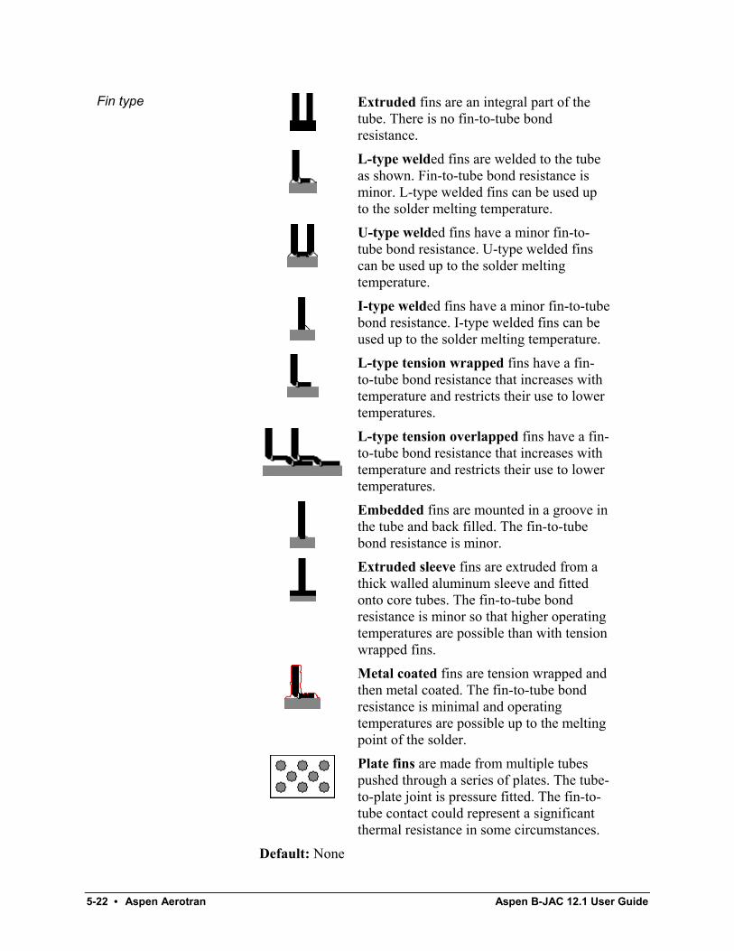
5-22 • Aspen Aerotran Aspen B-JAC 12.1 User Guide
Extruded fins are an integral part of the tube. There is no fin-to-tube bond resistance.
L-type welded fins are welded to the tube as shown. Fin-to-tube bond resistance is minor. L-type welded fins can be used up to the solder melting temperature.
U-type welded fins have a minor fin-to-tube bond resistance. U-type welded fins can be used up to the solder melting temperature.
I-type welded fins have a minor fin-to-tube bond resistance. I-type welded fins can be used up to the solder melting temperature.
L-type tension wrapped fins have a fin-to-tube bond resistance that increases with temperature and restricts their use to lower temperatures.
L-type tension overlapped fins have a fin-to-tube bond resistance that increases with temperature and restricts their use to lower temperatures.
Embedded fins are mounted in a groove in the tube and back filled. The fin-to-tube bond resistance is minor.
Extruded sleeve fins are extruded from a thick walled aluminum sleeve and fitted onto core tubes. The fin-to-tube bond resistance is minor so that higher operating temperatures are possible than with tension wrapped fins.
Metal coated fins are tension wrapped and then metal coated. The fin-to-tube bond resistance is minimal and operating temperatures are possible up to the melting point of the solder.
Plate fins are made from multiple tubes pushed through a series of plates. The tube-to-plate joint is pressure fitted. The fin-to-tube contact could represent a significant thermal resistance in some circumstances.
Default: None
Fin type

Aspen B-JAC 12.1 User Guide Aspen Aerotran • 5-23
Use this sheet to specify these parameters, when using twisted tapes: • Twisted tap ratio
Provide the ratio of the length of tape required to make a 180 degree twist to the width of the tape. The smaller the ratio, the tighter the twist.
• Twisted tape width Specify the width of twisted tape insert.
If you specified the rating or simulation program mode in the Application Options sheet, specify the following information, as applicable: • Number of tubes per bundle
This is the total number of tubes per bundle. If not specified, the program selects the maximum number of tubes per bundle.
• Tube passes per bundle This is the number of times the tube side fluid runs the length of the bundle.
• Tube rows deep per bundle The number of tube rows deep in the bundle, which is the number of rows crossed by fluid flowing across the outside of the tubes.
• Tube length This is the straight length of the tubes from front tubesheet to rear tubesheet or tangent point of the u-bends.
• Bundles in series This is the number of tube bundles per bay, or per exchanger, to which the tube side flow is fed in series. The program assumes that the flow outside the tube bundle is also in series.
• Bundles in parallel This is the number of tube bundles per bay or per exchanger to which the tube side flow is fed in parallel. The program assumes that the flow outside the tubes is also in parallel.
• Bays in series This is the number of bays fed with the tube side flow in series. Note that the flow outside the tubes is considered to be in parallel to the bays.
General Sheet
Geometry Sheet

5-24 • Aspen Aerotran Aspen B-JAC 12.1 User Guide
• Bays in parallel This is the number of bays fed with the tube side flow in parallel. The program also sets the flow outside the tubes in parallel to the bays.
• Fans per bay Enter 0 if the fan calculations are not required. The program attempts to determine the power requirements for the fans based on commercial fan manufacturer standards. These standards may not be applicable to an existing fan.
• Fan diameter This is the fan blade diameter. Enter 0 if the fan calculations are not required.
Use this sheet to specify the following header information: • Front header type
The type selected affects the overall dimensions of the exchanger and the price estimate. A Plug type header provides limited access to the tubes for cleaning. The removable bonnet type (default) or flanged covers provide full access to the tubes.
• Rear header type The type selected affects the overall dimensions of the exchanger and the price estimate. A Plug type header provides limited access to the tubes for cleaning. The removable bonnet type (default) or flanged covers provide full access to the tubes. U-tubes, which eliminate the rear header, are a low cost alternate if access to the tubes is not needed.
• Dual front header This indicates if a split front header and a single rear header are required. Split headers are commonly used when there is a large pass-to-pass temperature difference, which could result in excessive thermal stresses on the tubesheet. The default is single header.
• Header position This indicates the position of the header with respect to the ground and the tube orientation: horizontal (default), vertical, or top & bottoms (vertical tubes).
• Header slop This is the slope of the header with respect to ground level. Headers are sometimes sloped to insure drainage of the tube side fluid during condensation and for shutdown. The default is none.
Headers Sheet

Aspen B-JAC 12.1 User Guide Aspen Aerotran • 5-25
• Header box type Specify whether the header has the tubesheet and plug sheet of the same thickness (default) or different thicknesses. This item is primarily used for the budget cost estimate of the headers.
Use this sheet to specify these header dimensions: • Header width, depth, and height • Top bottom plate thickness • Plug sheet plate thickness • Tubesheet plate thickness • End plate thickness • Weld joint efficiency
You can specify the header size and thicknesses and the program will use these dimensions for the design and costing.
Default: none
Use this sheet to specify the following nozzle related information: • Nozzle nominal OD
Specify the size of the nozzles or let the program determine them based on standard pipe sizing formulas. By default the program determines the size based on TEMA standards.
• Number of nozzles When in design mode, you should let the program determine the number of nozzles. For most rating cases, the program also determines the appropriate number of nozzles.
• Nozzle flange rating The specification of the nozzle flange rating does not affect the thermal design calculations or the cost estimate. It is included in the input to make the specification of the heat exchanger more complete. The pressure-temperature charts are built into the program. The program determines the rating based on the design pressure, design temperature, and material of construction. The values are not limited to those shown next to the input field, but you should be sure to choose a rating that is consistent with the desired standard (ANSI, ISO, or DIN).
• Nozzle flange type and facing type Select the type of nozzle flange and facing that you want. The nozzle flange type and facing appear on the specification sheet. By default, they are unspecified.
Headers Dimensions Sheet
Nozzles Sheet
5-26 • Aspen Aerotran Aspen B-JAC 12.1 User Guide
Use the General sheet to specify the following construction options: • Plenum type
This is the type of ductwork used to direct air between the fan and the tube bundle. The plenum type affects the cost estimate and has a minor affect on the pressure drop outside the tubes.
• Recirculation type This indicates the type of air recirculation (if any) to be used for the exchanger. The type of recirculation appears on the specification sheet. However, it does not affect the actual design.
• Louvers control Louvers are used to provide process side temperature control and prevent damage to the bundle due to climatic conditions. Louvers affect the outside bundle pressure drop and the price estimate.
• Control action on air failure - louvers This indicates the desired response of the louvers upon air failure. The louver control appears on the equipment specification sheet.
• Bundle frame This is the material used in the fabrication of the bundle frame and is used in the cost estimate.
• Structure mounting This indicates where the exchanger will be mounted. Grade indicates the exchanger will require ground structural supports. Piperack indicates the exchanger will be mounted on existing piperacks. This option is used to estimate the price.
• Fan pitch control This is the type of control used for the fan blade pitch. The type of fan pitch appears on the equipment specification sheet.
• Fan drive type This is the type of driver used for the fans. The driver type appears on the equipment specification sheet.
• Control action on air failure - fan pitch This indicates the desired response of the fan pitch upon air failure. The air failure control appears on the equipment specification sheet.
General Construction Options

Aspen B-JAC 12.1 User Guide Aspen Aerotran • 5-27
• Steam coil Steam coils are sometimes used to prevent freeze-up in the tubes during severe climatic conditions. The requirement for steam coils appears on the equipment specification sheet.
• Soot blowers This is only available for the fired heat convection section. This equipment is used to periodically clean the heat transfer surface of fouling deposits. Use of soot blowers affect the size and price of the exchanger.
Use this sheet to specify the following design mode geometry constraints: • Tube length
The program uses the specified tube length increment when it increases or decreases the tube length. The default is 500 mm or 2 ft. The program considers the specified minimum/maximum length. The default minimum length considered is 1000 mm or 4 ft.; the default maximum length is 6000 mm or 20 ft. The maximum tube length must be greater or equal to the minimum length.
• Bundle width This is the minimum/maximum width of the bundle for a hot gas recuperator, fired heater convection section, or gas cooled exchanger that the program will consider. The default minimum width is 915 mm or 36 in. The default maximum bundle width, 2440 mm or 96 in., is based on normal shipping and handling limitations.
• Tube rows deep per bundle This sets the minimum/maximum number of rows deep per bundle for a hot gas recuperator, fired heater convection section, or a gas cooled type exchanger that the program will hold during design. The default minimum is 3 rows, and the default maximum is 20 rows.
• Tube passes per bundle This is the minimum/maximum number of tube passes per bundle limits. The default minimum is 1 pass.
• Minimum bundles in series This is the minimum number of bundles in series for a hot gas recuperator, fired heater convection section, or a gas cooled exchanger. Note that the tube side and outside fluids flow in series through the exchanger bundles.
Design Data Geometry Design Constraints Sheet

5-28 • Aspen Aerotran Aspen B-JAC 12.1 User Guide
• Minimum bundles in parallel This is the minimum number of bundles in parallel for a hot gas recuperator, fired heater convection section, or a gas cooled exchanger. Note that the program considers both the tube side and outside fluids flow in parallel.
• Minimum bays in series This is the minimum number of bays in series for air cooler applications. Note that the tube side flow is considered to be series and outside fluid flow is considered to be in parallel through the exchanger.
• Minimum bays in parallel This is the minimum number of bays in parallel for air cooler applications. Note that the program considers both the tube side and outside fluids flow to be in parallel.
For air cooler applications, you can specify the these geometry constraints: • Bay width
This is the minimum/maximum width of a bay that the program will consider. The default minimum is 915 mm or 36 in; the default maximum is 5238 mm or 192 in.
• Tube rows deep per bay This is the minimum/maximum number of tube rows per bay that the program will consider. The minimum default is 3, and less than 3 rows is not recommended. The maximum default is 20, and more than 20 rows is not recommended.
• Tube passes per bay This is the minimum/maximum number of tube passes per bay that the program will consider. The program attempts to maximize the number of tube passes within the limits of maximum velocity and tube side pressure drops. The minimum default is 1. The maximum default will restrict the maximum tube passes to 2 passes per tube rows deep.
• Minimum fans per bay This design restriction forces the program to design the bay with a width and length that will accommodate the specified minimum number of fans. The default is 1. Multiple fans per bay are sometimes desirable so that exchangers can be operated at reduced loads by turning fans off. If a fan fails, the exchanger could also operate with a reduced load.

Aspen B-JAC 12.1 User Guide Aspen Aerotran • 5-29
Use this sheet to specify the following process design constraints: • Minimum fluid velocity
The minimum velocities specified for tube side/outside are the lowest velocities the program accepts in design mode. The program may not find a design that satisfies this minimum, but it will issue a warning if the design it chooses does not satisfy the minimum.
• Maximum fluid velocity The maximum velocities specified for tube side/outside are the highest velocities the program accepts in design mode. The program tries to maximize the velocities within the allowable pressure drops and the maximum allowable velocities. Therefore, this constraint does not enter into the design mode logic. For two phase flow, it is the vapor velocity at the point where there is the most vapor.
• Minimum % excess surface are required This is the percent of excess surface required in the design to satisfy the heat transfer surface area requirements.
Use this sheet to select the material of construction for following items:
Tube Select a generic material, a general material class, for the tubes. The default is carbon steel.
Fins Select a generic material, a general material class, for the fins, if present. The default is aluminum.
Header Select a generic material, a general material class, for the hot side components. The default is carbon steel.
Plugs Select a generic material, a general material class, for the plugs, if present. The default is carbon steel.
Gasket Select a generic material, a general material class, for the gaskets, if present. If not specified, the program uses compressed fiber as the material for the mechanical design and cost estimate.
To specify a specific material grade for any of these items, click the Search Databank button.
If you specify a material designator for the tube material, the program retrieves the thermal conductivity of the tube from its built-in databank. However, if you have a tube or fin material that
Process Design Constraints Sheet
Materials Sheet

5-30 • Aspen Aerotran Aspen B-JAC 12.1 User Guide
is not in the databank, then you can specify the tube or fin thermal conductivity on this sheet.
Use this sheet to specify these design specifications: • Design code - ASME (American), CODAP (French), or AD-
Merkblatter (German) - is used to tell the program which basic mechanical design calculations to follow and also to make the heat exchanger specification more complete.
• Code stamp Select Yes if the box headers for the unit are to be designed and stamped to the selected pressure vessel design code. The default is No � code stamp is not required
• TEMA class If you want the heat exchanger to be built according to TEMA standards, select the appropriate TEMA class - B, C, or R. If TEMA is not a design requirement, specify Code only and the program will use only the design code to determine the mechanical design. API 661 may also be specified. By default the program uses the standards defined in Program Settings under Tools.
• Material standard - ASTM, AFNOR, or DIN - determines the selection of materials listed in the input for materials of construction. By default the program uses the standards defined in the Program Settings under Tools.
• Dimensional standard- ANSI (American), ISO (International), or DIN (German) - applies to such things as pipe cylinder dimensions, nozzle flange ratings, and bolt sizes. DIN also encompasses other construction standards such as standard tube pitches. This selection is included primarily to make the heat exchanger specification complete, although it does have some subtle effects on the thermal design through the basic mechanical design. By default the program uses the standards defined in the Program Settings under Tools.
• Design pressure Used in the mechanical design calculations, the specified design pressure influences the shell, head, and tubesheet required thicknesses, and therefore affects the thermal design. If you do not specify a value, the program defaults to the operating pressure plus 10% rounded up to a logical increment. This is in gauge pressure, which is one atmosphere less than the equivalent absolute pressure.
Design Specifications Sheet

Aspen B-JAC 12.1 User Guide Aspen Aerotran • 5-31
• Vacuum design pressure By default vacuum design pressure is not calculated for vacuum service. However, if the heat exchanger is going to operate under a full or partial vacuum, you should specify a vacuum service design pressure.
• Test pressure is the pressure at which the manufacturer will test the heat exchanger. This has no effect on the thermal design, but is included to make the heat exchanger specification more complete. The default is Code.
• Design temperature Used in the mechanical design calculations, the design temperature influences the shell, head, and tubesheet required thicknesses, and therefore affects the thermal design. If not specified, the program defaults to the highest operating temperature plus 33ºC (60ºF) rounded down to a logical increment.
• Corrosion allowance is included in the thickness calculations for cylinders and tubesheets, and therefore has a subtle effect on thermal design. The default is 0.125 in. or 3.2 mm for carbon steel; 0 for other materials
The design code is used to tell the program which basic mechanical design calculations to follow and also to make the heat exchanger specification more complete. Choices are: • ASME (American) • CODAP (French) • AD-Merkblatter (German)
The program defaults to the design code specified in the Program Settings under Tools.
The design code has a subtle, but sometimes significant effect on the thermal design. This is because the design code determines the : • Required thicknesses for the shell and heads, therefore
affecting the number of tubes • Thickness of the tubesheet, therefore affecting the effective
heat transfer area • Dimensions of the flanges and nozzle reinforcement, therefore
affecting the possible nozzle and baffle placements
Due to the fact that the mechanical design calculations themselves are very complex, the Aspen Aerotran program only includes some of the basic mechanical design calculations. The full calculations are the function of the Aspen B-JAC TEAMS program.
Design Code

5-32 • Aspen Aerotran Aspen B-JAC 12.1 User Guide
Process Sheet Use this sheet to specify: • Heat transfer coefficient
Normally, the film coefficients are two of the primary values you want the program to calculate. However, there may be cases where you want to force the program to use a specific coefficient, perhaps to simulate a situation that the program does not explicitly cover. You can specify neither, either, or both.
• Heat transfer coefficient multiplier You can specify a factor that becomes a multiplier on the film coefficient, which is calculated by the program. You may want to use a multiplier greater than 1 if you have a construction enhancement that is not covered by the program, for example tube inserts or internally finned tubes. You can use a multiplier of less than 1 to establish a safety factor on a film coefficient. This would make sense if you were unsure of the composition or properties of a fluid stream.
• Pressure drop multiplier Similar to the multipliers on the film coefficients, you can also specify a factor that becomes a multiplier on the bundle portion of the pressure drop, which is calculated by the program. It does not affect the pressure drop through the inlet or outlet nozzles or heads. These multipliers can be used independently or in conjunction with the multipliers on film coefficients.
• Maximum allowable heat flux For vaporizing applications, it is often important to limit the heat flux (heat exchanged per unit area) to avoid the generation of too much vapor so quickly as to blanket the tube surface, resulting in a rapid decline in the film coefficient. The Aspen Aerotran program has built in limits on the heat flux, but you can also establish your own limit by specifying a value for this item.
• Vaporization curve adjustment for pressure The program defaults to calculating the vaporization curve in isobaric conditions (constant operating pressure). You may specify non-isobaric conditions and the program will allocate the specified pressure drop based on heat load increments along the vaporization curve. The vapor/liquid equilibrium at various temperatures will be calculated using an adjusted operating pressure.
Program Options Thermal Analysis

Aspen B-JAC 12.1 User Guide Aspen Aerotran • 5-33
MTD Sheet Use this sheet to specify: • Mean temperature difference
Usually, the program determines the MTD; however you can override the program calculated corrected (or weighted) MTD by specifying a value here.
• Minimum allowable temperature approach You can limit the minimum approach temperature. The program will increase the number of shells in series and/or limit the exchanger to a one pass-one pass countercurrent geometry to meet the minimum approach temperature. The default is 3 to 5°F depending on application
• Minimum allowable MTD correction factor Since most of the correction factor curves become very steep below 0.7, the Aerotran program defaults to 0.7 as the minimum F factor before going to multiple shells in series in design mode. The only exception is the X-type shell, where the program allows the F factor to go as low as 0.5 in design mode. In rating mode, the default is 0.5. Use this item to specify a lower or higher limit.
• Flow direction for single pass exchangers For special economizer applications, you can indicate counter current or co-current flow which will adjust the temperature driving force profile.
Correlations Sheet Use this sheet to specify condensation and vaporization options.
Condensation Options • Desuperheating heat transfer method
The program defaults to determining the tube wall temperature at the hot side inlet. If this option is enabled, the program assumes a desuperheating zone exists from the specified inlet temperature down to the dew point. The program defaults to determining the tube wall temperature at the hot side inlet. If the wall temperature is below the dew point, the program assumes that the tube wall is "wet" with condensation and uses a condensing coefficient for heat transfer. If the tube wall temperature is above the dew point, the program determines at what hot side gas temperature the tube wall temperature falls below the dew point. This hot side

5-34 • Aspen Aerotran Aspen B-JAC 12.1 User Guide
gas temperature would represent the low temperature for the desuperheating zone.
• Condensation heat transfer model The Mass transfer film model (default) is based on a Colburn-Hougen correlation for condensable(s) with noncondensable(s) and a Colburn-Drew correlation for multiple condensables. The Modified proration model is an equilibrium method based on a modification of the Silver-Bell correlation. Researchers have developed several different methods of predicting the film coefficient for a condensing vapor. Each has its strengths and weaknesses. If the composition of the vapor is well known, the mass transfer film model is the most accurate.
• Tube side two phase heat transfer correlation The two major two phase condensing correlations that determine tube side film coefficients referenced in the industry are the Taborek (default) and the Chen methods.
• Liquid subcooling heat transfer method Select the calculation method to determine the liquid subcooling coefficient for a condensing application. For most applications, the larger of the free or forced convection should be considered.
Vaporization Options • Indicator to suppress nucleate boiling coefficient
If selected, the program suppresses the nucleate boiling coefficient when determining the overall film coefficient.
• Minimum temperature difference for nucleate boiling You can specify a minimum temperature difference requirement for nucleate boiling to be considered.
• Correlation for 2 phase tube side pressure drop You can select the tube side two phase pressure drop correlation to be applied: Lochart-Martinelli, Friedel, Chisholm, McKetta, or Nayyar. If not specified, the program selects the one most appropriate for the application.
• Tube side two phase heat transfer correlation The major two-phase vaporization correlations to determine tube side film coefficients referenced in the industry are the Steiner-Taborek (default), Collier-Polley, Chen, Dengler-Addoms, and the Guerrieri-Talty methods.

Aspen B-JAC 12.1 User Guide Aspen Aerotran • 5-35
Calculation Options Sheet Use this sheet to specify these calculation options: • Simulation mode tolerance
Specify the convergence tolerance for the simulation mode of the program. Note that a very low convergence tolerance may result in a longer calculation time.
• Maximum number of design mode iterations In the Design Mode the program will reiterate through the specified design parameters to converge on the lowest cost solution. You may set the maximum number of iterations for the optimization.
• Number of calculation intervals The program does an interval analysis by dividing the heat exchanger into sections. Specify how many interval sections are to be considered.
• Type of interval calculation The program does an interval analysis by dividing the heat exchanger into sections. Select whether the program is to use equal heat load or equal temperature increments for the sectional analysis of the exchanger.
• Heat transfer by radiation and convection For some waste heat recovery applications, it may be appropriate to include the radiation effects of heat transfer in addition to the normal convective heat transfer.
Change Codes Sheet Use the Change Codes sheet to specify those items that can be specified only with a change code. Change codes are processed after all of the other input and override any previously set value.
One of the best uses of the Change Codes sheet is to provide a visual path of the various changes you make during program execution. For this purpose, we recommend that you place changes for a particular alternative design on a separate line.
The format for change code entries is: CODE=value
For instance, if you specify the tube outside diameter as 20 mm in the regular input screens, then enter the change code TODX=25, the 25 will override the 20. If you enter the same change code more than once, the last value will prevail.
Another good use of the Change Code sheet is to "chain" to another file containing only change codes. This is especially
Change Codes

5-36 • Aspen Aerotran Aspen B-JAC 12.1 User Guide
convenient if you have a line of standard designs, which you want to use after you have found a similar solution in design mode.
To do this, use the FILE= change code, followed by the name of the file containing the other change codes. with the file type, for example, ABC-1.BJI. The other file must also have a .BJI filetype. You can create this change code file with a standard edit program.
For example, the entry FILE=S-610-2 would point to a file named S-610-2.BJI, containing the following data:
MODE=2,TLNG=3600,TPPB=2,TRBU=6,BUSE=2
Design Mode Change Codes These are the design mode change codes that are available for Aerotran:
MODE= program mode: 1=design 2=rating
TLMN= tube length, minimum
TLMX= tube length, maximum
BWMN= minimum bay width
BWMX= maximum bay width
MBAP= minimum bays in parallel
MBAS= minimum bays in series
MBUW= maximum bundle width
MFBA= minimum fans per bay
TRMN= minimum tube rows per bay
TRMX= maximum tube rows per bay
TPMN= minimum tube passes
TPMX= maximum tube passes
Rating Mode Change Codes These are the rating mode change codes that are available for Aerotran:
MODE= program mode: 1=design 2=rating
BAPA= number bays in parallel
BASE= number bays in series
BUPA= number bundles in parallel
BUSE= number bundles in series

Aspen B-JAC 12.1 User Guide Aspen Aerotran • 5-37
TRBU= number tube rows per bundle
TLNG= straight tube length
TNUM= number of tubes
TPPB= tube passes per bundle
FAOD= fan outside diameter
FAPB= number of fans per bay
Tube & Fin Change Codes These are the tube and fine change codes that are available for Aerotran:
FNMT= fin material
FNOD= fin outside diameter
FNSP= number of fins per unit length
FNSW= fin segment width
FNTK= fin thickness
FNTY= type of fin:
1 = none 6 = L-tension wrapped 11= plate
2 = extruded 7 = L-tension overlapped
3 = L-type weld 8 = embedded
4 = U-type weld 9 = extruded sleeve
5 = I-type weld 10= metal coated
TODX= tube outside diameter
TWTK= tube wall thickness
Mechanical Options Change Codes These are the mechanical options change codes that are available for Aerotran:
DTYP= type of draft: 1=forced 2=induced 3=not applicable
PARR= pass arrangement: 1=horizontal or mixed 2= vertical
RPIT= tube pitch between tube rows deep
TPAT= tube pattern: 1=staggered 2=in-line
TPIT= tube pitch in the face row

5-38 • Aspen Aerotran Aspen B-JAC 12.1 User Guide
General Change Codes This is the general change code that is available for Aerotran:
FILE= specify the name of the file that contains the change codes
Aerotran Results The Results Section is divided into four sections: • Design Summary • Thermal Summary • Mechanical Summary • Calculation Details
The Design Summary Section is subdivided into four sections: • Input Summary • Optimization Path • Recap of Designs • Warnings & Messages
This section provides you with a summary of the information specified in the input file. It is recommended that you request the input data as part of your printed output so that it is easy to reconstruct the input, which led to the design.
This part of the output is the window into the logic of the program. It shows some of the heat exchangers the program has evaluated in trying to find one that satisfies your design conditions. These intermediate designs can also point out the constraints that are controlling the design and point out what parameters you could change to further optimize the design.
To help you see which constraints are controlling the design, the conditions that do not satisfy your specifications are noted with an asterisk (*) next to the value. The asterisk will appear next to the required tube length if the exchanger is undersurfaced, or next to a pressure drop if it exceeds the maximum allowable. Column headings are described below:
In design mode, the Aerotran program will search for a heat exchanger configuration that will satisfy the desired process conditions. It will automatically change a number of the geometric parameters as it searches. However Aerotran will not automatically evaluate all possible configurations, and therefore it may not
Design Summary
Input Summary
Optimization Path

Aspen B-JAC 12.1 User Guide Aspen Aerotran • 5-39
necessarily find the true optimum by itself. It is up to the user to determine what possible changes to the construction could lead to a better design and then present these changes to the program.
Aerotran searches to find a design that satisfies the following:
(1) enough surface area to do the desired heat transfer
(2) pressure drops within the allowable
(3) physical size within acceptable limits
(4) velocities within an acceptable range
(5) mechanically sound and practical to construct
In addition to these criteria, Aerotran also determines a budget cost estimate for each design. However the cost does not affect the program's logic for optimization.
There are several mechanical parameters which directly or indirectly affect the thermal performance of an air cooled type heat exchanger. It is not practical for the program to evaluate all combinations of these parameters. In addition, the acceptable variations are often dependent upon process and cost considerations that are beyond the scope of the program (for example the cost and importance of cleaning). Therefore the program automatically varies only a number of parameters that are reasonably independent of other process, operating, maintenance, or fabrication considerations. The parameters that are automatically optimized are:
tubes in face row number rows deep tube length bundles in series bundles in parallel number of tubes tube passes bays in series bays in parallel
The design engineer should optimize the other parameters, based on good engineering judgment. Some of the important parameters to consider are:
fin density tube outside diameter fan size fin type tube pitch tube pattern nozzle sizes tube type exchanger orientation materials fluid allocation tube wall thickness
Face Rows: The number of tubes in the first tube row exposed to the outside bundle flow. In the design mode, the program will minimize the number of tubes in the face row to maximize the air side and tube side velocities. For an air cooler application, face rows will be incremented based upon Bay width limits set in design constraints and pressure drop limits that have been set. For
Optimization Path Items

5-40 • Aspen Aerotran Aspen B-JAC 12.1 User Guide
other types of equipment (economizers sections), the face rows optimization will be based upon bundle width limits set.
Rows Deep: The number of tube rows passed by the outside flow from entrance to exit. In the design mode, the program will minimize the number of rows deep to meet minimum surface area required and be within allowable pressure drop limits. For an air cooler application, face rows deep will be incremented based upon Bay rows deep limits set in design constraints and pressure drop limits that have been set. For other types of equipment (economizers sections), the rows deep optimization will be based upon the bundle rows deep limits set.
Tube Length: The straight length of one tube is from inlet header to outlet header or u-bend. Once the smallest bundle/bay size has been found, the program optimizes the tube length to the shortest standard length, within the allowable range, which will satisfy surface area, pressure drop, and velocity requirements. The length is incremented or decremented based on the tube length increment and is limited by the minimum tube length and maximum tube length. Each of these can be specified in the input. The actual tube Length will be shown which is the length of the straight tubes or the straight length to the tangent for U-tubes. This includes the portion of the tube, which is in the tubesheet. This length will include the portion of the tube in the tubesheet, which is ineffective for heat transfer.
Tube Pass: The number of tube side passes per bay that the tube side flow makes across the outside flow. The program seeks the maximum reasonable number of tube passes that gives a pressure drop and velocity within the maximums allowed. The program wants to maximize the tube side velocity thereby maximizing the tube side film coefficient and minimizing any velocity dependent fouling.
Bundles in Parallel: The number of tube bundles in parallel per bay or per exchanger. The program will automatically increase the number of bundles in parallel when it reaches the maximum allowable bundle width and minimum allowable tube length and still is unable to satisfy the allowable pressure drop. Note that both the outside streams and tube side streams are considered to be flowing in parallel.
Bundles in Series: The number of tube bundles in parallel per bay or per exchanger. The program will automatically increase the number of bundles in parallel when it reaches the maximum allowable bundle width and minimum allowable tube length and still is unable to satisfy the allowable pressure drop. Note that both

Aspen B-JAC 12.1 User Guide Aspen Aerotran • 5-41
the outside streams and tube side streams are considered to be flowing in parallel.
Bays in Parallel: The number bays with the tube side flow in parallel for air cooled applications only. The program will automatically increase the number of bays in parallel when it reaches the maximum allowable bay width and minimum allowable tube length and still is unable to satisfy the allowable pressure drop. Note that both the shell side streams and tube side streams are considered to be flowing in parallel.
Bays in Series: The number bays with the tube side flow in series for air cooled applications only. The program will automatically increase the number of bays in series when it reaches the maximum allowable bay width and tube length and still is unable to find a design with enough heat transfer area. It will also go to exchangers in series when the correction factor on the MTD falls below 0.7 (or the minimum allowable correction factor specified in the input). Note that both the outside stream is considered to be in parallel flow and the tube side stream is considered to be flowing in series.
Area Calculated: The calculated required surface area. This area is determined by the calculated heat load, corrected mean temperature difference, and the overall heat transfer coefficient. This area will be denoted with an * if the exchanger is undersurfaced.
Area Actual: The actual total outside surface area that is available for heat transfer. This is based upon the effective tube length that does not include the length of the tubes in the tubesheet(s).
Outside Pressure Drop: The total outside pressure drop calculated for flow outside the tubes. The pressure drop will be denoted with an * if it exceeds the allowable.
Tube Pressure Drop: The total tube side pressure drop calculated for flow through the tubes. The pressure drop will be denoted with an * if it exceeds the allowable.
Total Price: This is the estimated budget price for the total number of heat exchangers in series and in parallel.
The recap of design cases summarizes the basic geometry and performance of all designs reviewed up to that point. The side by side comparison allows you to determine the effects of various design changes and to select the best exchanger for the application. As a default, the recap provides you with the same summary information that is shown in the Optimization Path. You can customize what information is shown in the Recap by selecting the
Recap of Designs
5-42 • Aspen Aerotran Aspen B-JAC 12.1 User Guide
Customize button. You can recall an earlier design case by selecting the design case you want from the Recap list and then select the Select Case button. The program will then regenerate the design results for the selected case.
Aspen B-JAC provides an extensive system of warnings and messages to help the designer of heat exchanger design. Messages are divided into five types. There are several hundred messages built into the program. Those messages requiring further explanation are described here.
Warning Messages: These are conditions, which may be problems, however the program will continue.
Error Messages: Conditions which do not allow the program to continue.
Limit Messages: Conditions which go beyond the scope of the program.
Notes: Special conditions which you should be aware of.
Suggestions: Recommendations on how to improve the design.
The Thermal Summary section summarizes the heat transfer calculations, pressure drop calculations, and surface area requirements. Sufficient information is provided to allow you to make thermal design decisions. The Thermal Summary Section is subdivided into four headings: • Performance • Coefficients & MTD • Pressure Drop • API Sheet
Performance This section provides a concise summary of the thermal process requirements, basic heat transfer values, and heat exchanger configuration on the following sheets: • General Performance • Thermal Resistance Analysis
General Performance In the general performance section, flow rates, Gases (in/out) and Liquids (in/out), for the outside and tube sides are shown to summarize any phase change that occurred in the exchanger.
Warnings & Messages
Thermal Summary
Performance

Aspen B-JAC 12.1 User Guide Aspen Aerotran • 5-43
The Temperature (in/out) for both side of the exchanger are given along with Dew point and bubble point temperatures for phase change applications.
Film coefficients for the shell and tube sides are the weighted coefficients for any gas cooling/heating and phase change that occurred in the heat exchanger.
Velocities for single phase applications are based on an average density. For condensers, the velocity is based on the inlet conditions. For vaporizers, it is based on the outlet conditions. Outside velocities are the crossflow velocity through the cross-section.
Overall performance parameters are given, such as Heat exchanged, MTD with any applied correction factor and the effective total surface area. For single phase applications on both sides of the shell, a MTD correction factor will be applied in accordance with TEMA standards. For multi-component phase change applications, the MTD is weighted based upon a heat release curve. The effective surface area does not include the U-bend area for U-tubes unless it was specified to do so.
The exchanger geometry provided in the summary includes: TEMA type, exchanger position, number of shells in parallel and in series, exchanger size, number of tubes and tube outside diameter, baffle type, baffle cut, baffle orientation, and number of tube passes.
Thermal Resistance Analysis This portion gives information to help you evaluate the surface area requirements in the clean, specified fouled (as given in the input), and the maximum fouled conditions.
The clean condition assumes that there is no fouling in the exchanger, in the new condition. The overall coefficient shown for this case has no fouling resistance included. Using this clean overall coefficient, the excess surface area is then calculated.
The specified foul condition summarizes the performance of the exchanger with the overall coefficient based upon the specified fouling.
The maximum fouled condition is derived by taking the specified fouling factors and increasing them (if the exchanger is oversurfaced) or decreasing them (if undersurfaced), proportionately to each other, until there is no over or under surface.

5-44 • Aspen Aerotran Aspen B-JAC 12.1 User Guide
The distribution of overall resistance allows you to quickly evaluate the controlling resistance(s). You should look in the "Clean" column to determine which film coefficient is controlling, then look in the "Spec. Foul" column to see the effect of the fouling resistances. The difference between the excess surface in the clean condition and the specified fouled condition is the amount of surface added for fouling.
You should evaluate the applicability of the specified fouling resistances when they dictate a large part of the area, say more than 50%. Such fouling resistances often increase the diameter of the heat exchanger and decrease the velocities to the point where the level of fouling is self-fulfilling.
Coefficients & MTD This output section shows the various components of each film coefficient. Depending on the application, one or more of the following coefficients are shown: • desuperheating • condensing • vapor sensible • liquid sensible • boiling • liquid cooling
The Reynolds number is included so that you can readily evaluate if the flow is laminar (under 2000), transition (2000-10000), or turbulent (over 10000).
The fin efficiency factor is used in correcting the tube side film thermal resistance and the tube side fouling factor resistance.
The mean metal temperature of the shell is the average of the inlet and outlet temperatures on the shell side. The mean metal temperature of the tube wall is a function of the film coefficients on both sides as well as the temperatures on both sides. These two temperatures are intended for use in the mechanical design in order to determine the expansion joint requirements in a fixed tubesheet heat exchanger.
The calculated corrected MTD (Mean Temperature Difference) for no phase change applications is the product of the LMTD (Log Mean Temperature Difference), the correction factor (F), and the longitudinal baffle efficiency factor (if using an F, G, or H shell). For phase change applications, the process is divided into a number of intervals and a MTD is determined for each interval.
Coefficients & MTD

Aspen B-JAC 12.1 User Guide Aspen Aerotran • 5-45
The overall MTD for the exchanger is then determined by weighting the interval MTDs based on heat load. If you have specified a value for the Corrected Mean Temperature Difference in the input, it is this value which the program uses in the design instead of the calculated Corrected MTD.
The flow direction is displayed when there is a single tube pass, in which case it is either counter-current or co-current.
The heat flux is the heat transferred per unit of surface area. This is of importance for boiling applications where a high flux can lead to vapor blanketing. In this condition, the rapid boiling at the tube wall covers the tube surface with a film of vapor, which causes the film coefficient to collapse. The program calculates a maximum flux for nucleate boiling on a single tube and a maximum flux for bundle boiling (nucleate and flow boiling), which can be controlled by other limits (e.g., dryout). If you specify a maximum flux in the input, this overrides the program calculated maximum flux. To analyze this data, you should check to see if the maximum flux is controlling. If it is, consider reducing the temperature of the heating medium.
Pressure Drop The Pressure Drop section reports the following output: • Pressure drop distribution • User- specified bundle multiplier • Velocity distribution • Distribution of overall resistance
Pressure drop distribution The pressure drop distribution is one of the most important parts of the output for analysis. You should observe if significant portions or the pressure drop are expended where there is little or no heat transfer (inlet nozzle, entering bundle, through bundle, exiting bundle, and outlet nozzle). If too much pressure drop occurs in a nozzle, consider increasing the nozzle size. If too much is consumed entering or exiting the bundle, consider increase the face area of the bundle.
The program determines the dirty pressure drop in the tubes by estimating a thickness for the fouling, based on the specified tube side fouling resistance, which decreases the cross-sectional area for flow.
Pressure Drop

5-46 • Aspen Aerotran Aspen B-JAC 12.1 User Guide
User specified bundle multiplier The user specified bundle multiplier, which you can specify in the input, is included in the bundle portion of the calculated pressure drop, clean and dirty.
Velocity distribution The velocity distribution, between the inlet and outlet nozzle, is shown for reference. In other parts of the output, the velocity, which is shown for the shell side, is the diametric crossflow velocity. For the tube side it is the velocity through the tubes. For two phase applications, the velocities for crossflow, through baffle windows, and through tubes are the highest velocities based on the maximum vapor flow.
Distribution of Overall Resistance The distribution of overall resistance allows you to quickly evaluate the controlling resistance(s). You should look in the "Clean" column to determine which film coefficient is controlling, then look in the "Spec. Foul" column to see the effect of the fouling resistances. The difference between the excess surface in the clean condition and the specified fouled condition is the amount of surface added for fouling.
You should reevaluate the applicability of the specified fouling resistances when they dictate a large part of the area, say more than 50%. Such fouling resistances often increase the diameter of the heat exchanger and decrease the velocities to the point where the level of fouling is self-fulfilling.
API Sheet The Aspen Aerotran program generates the complete API data sheet.
Summary Section is subdivided into two sections: • Exchanger Dimensions • Setting Plan & Tubesheet Layout
API Sheet
Mechanical Summary

Aspen B-JAC 12.1 User Guide Aspen Aerotran • 5-47
Exchanger Dimensions These are the exchanger dimensions that are reported: Item Description Unit length The total length of the exchanger includes the tube
length and the depth of the inlet and outlet headers (if any).
Unit width The unit width is the total width of the entire unit, which includes side frames and/or ducting.
Bays in parallel
The total number of bays in parallel with the tube side flow in parallel.
Bays in series The total number of bays in series with the tube side flow in series.
Tubes/bundle Tubes/bay
The total number of tubes per bundle or bay.
Fan specifications
Fan blade and motor information is included if the unit was specified as a forced or induced air source. Fan selection is based upon the Moore Fan correlations.
Tube summary The tube summary includes: tube material, tube length, tube O.D., tube wall thickness, tube pitch first row, tube pitch first row, tube pattern, pass type, and area ratio. For additional information on these items, see the geometry input.
Fin specifications
The fin specification summary includes: Fin Material, Fin Type, Fin OD, Fin thickness, Fin density, Fin segment width. For additional information on these items, see the geometry input.
Setting Plan A scaled setting plan is provided. Setting plan shows overall dimensions, inlet / outlet nozzle arrangement and fans (if applicable).
Tubesheet Layout The tubesheet layout drawing is displayed directly after the tube details. The complete tube layout shows all tubes and their arrangement in the tube bank. Each tube row is listed with the number of tubes per row. Three additional graphics show the number of tubes per pass and tube pass arrangement, the tube pattern with tube pitch dimensions, and the finned tube geometry with dimensions.
Exchanger Dimensions
Setting Plan & Tubesheet Layout
5-48 • Aspen Aerotran Aspen B-JAC 12.1 User Guide
The Calculation Details Section is subdivided into two headings: • Interval Analysis - Tube Side • VLE - Tube Side
The Interval analysis section provides you with table of values for liquid properties, vapor properties, performance, heat transfer coefficients and heat load over the tube side temperature range.
Flow regimes are mapped in this section with the corresponding overall calculated film coefficients. The overall film coefficients are base upon the following:
The liquid coefficient is the calculated heat transfer coefficient assuming the total flow is all liquid.
The gas coefficient is the calculated heat transfer coefficient assuming the total flow is all vapor.
Flow regimes are mapped in this section with the corresponding overall calculated film coefficients. The overall film coefficients are base upon the following:
"Desuperheating Dry Wall" is for the part of the desuperheating load, which is removed, where no condensing is occurring. This only happens when the tube wall temperature is above the dew point temperature. In such a case, the film coefficient is based on a dry gas rate and the temperature difference is based on the inlet temperature.
"Desuperheating Wet Wall" which shows the part of the desuperheating load which is removed coincident with condensation occurring at the tube wall. This case is more common. The film coefficient and temperature difference are the same as the first condensing zone.
Liquid Cooling coefficient is for the cooling of any liquid entering and the condensate after it has formed and flows further through the heat exchanger. The program assumes that all liquid will be cooled down to the same outlet temperature as the vapor.
The dry gas coefficient is the heat transfer coefficient when only gas is flowing with no condensation occurring. It is used as the lower limit for the condensing coefficient for pure component condensation and in the mass transfer and proration model for complex condensation applications.
The pure condensing coefficients (shear and gravity) are the calculated condensing coefficients for the stream for that regime. The resulting pure condensing coefficient is a pure shear
Calculation Details
Interval Analysis - Tube Side
Heat Transfer Coefficient - Single Phase
Heat Transfer Coefficient - Condensation

Aspen B-JAC 12.1 User Guide Aspen Aerotran • 5-49
coefficient, pure gravity coefficient or a proration between the two, depending on the condensing regime.
The condensing film coefficient is the heat transfer coefficient resulting from the combined effects of the pure condensing coefficient and the dry gas coefficient.
The two phase factor is the correction factor applied to the liquid coefficient to calculate the two phase heat transfer coefficient.
The two phase coefficient is the heat transfer coefficient calculated based on the combined liquid and vapor flow.
The nucleate coefficient is the heat transfer coefficient due to the nucleation of bubbles on the surface of the heat transfer surface.
The vaporization film coefficient is the heat transfer coefficient for the specified side resulting from the vectorial addition of the two-phase and nucleate boiling coefficient. Observe the change in the film coefficient to see if it decreases severely at the end of the vaporizing range. This usually indicates that the tube wall is drying out and the film coefficient is approaching a dry gas rate. If a significant percentage of the area required is at this low coefficient, consider a higher circulation rate (less vaporized each time through) if it is a reboiler.
If the Aspen Aerotran program generated the heat release curve, the following VLE information is provided: • Vapor-liquid equilibrium
The condensation or vaporization curve will be provided as a function of equal heat load increments or temperature increments. Cumulative heat load and vapor/liquid flow rates as a function of temperature will be shown.
• Condensation/vaporization details Component flow rates as function of temperature increments will be provided.
• Vapor properties Vapor properties will be provided as a function of temperature increments.
• Liquid properties Liquid properties will be provided as a function of temperature increments.
Heat Transfer Coefficient - Vaporization
VLE - Tube Side

5-50 • Aspen Aerotran Aspen B-JAC 12.1 User Guide
Aerotran Design Methods In design mode, the Aspen Aerotran program searches for a heat exchanger configuration to satisfy the desired process conditions. It automatically change a number of the geometric parameters as it searches. However, Aspen Aerotran will not automatically evaluate all possible configurations, and therefore it may not necessarily find the true optimum by itself. It is up to the user to determine what possible changes to the construction could lead to a better design and then present these changes to the program.
Aspen Aerotran searches to find a design, which satisfies the following: • Enough surface area to do the desired heat transfer • Pressure drops within the allowable • Physical size within acceptable limits • Velocities within an acceptable range • Mechanically sound and practical to construct
In addition to these criteria, Aspen Aerotran also determines a budget cost estimate for each design. However cost does not affect the program's logic for optimization.
There are over thirty mechanical parameters that directly or indirectly affect the thermal performance of a heat exchanger. It is not practical for the program to evaluate all combinations of these parameters. In addition, the acceptable variations are often dependent upon process and cost considerations, which are beyond the scope of the program (for example the cost and importance of cleaning). Therefore the program automatically varies only a number of parameters which are reasonably independent of other process, operating, maintenance, or fabrication considerations. The parameters which are automatically optimized are: bundle/bay width, tube rows, bundles/bays in series, tube length, tube passes, bundles/bays in parallel, number of tubes, and fan number.
The design engineer should optimize the other parameters, based on good engineering judgment. Some of the important parameters to consider are: tube outside diameter, fin type, materials, tube pitch, fin dimensions, nozzle sizes, tube type, fin density, fan requirements, tube wall thickness, exchanger orientation, materials, tube pattern, and tubesheet type.
The program attempts to optimize on the most effective exchanger geometry that meets all the specified design criteria, while requiring the least amount of heat transfer area. The optimization logic changes the:
Optimization Logic
Optimization of Heat Transfer Area

Aspen B-JAC 12.1 User Guide Aspen Aerotran • 5-51
• Bundle/bay length, width, and tube rows • Number of tubes • Number of tube passes
Minimum and maximum limits for each of these items can be specified in the input.
The program attempts to maximize the heat transfer coefficients by maximizing velocities within the following limitations: • Maximum allowable velocity • Allowable pressure drop • Physical construction limitations
The pressure drop inside the tubes includes pressure losses: • Through the bundle • Accessory losses due to louvers, fan guards, and steam coils
The pressure drop inside the tubes includes pressure losses: • Through the inlet and outlet nozzles • Entering and exiting the tubes • Through the tubes
The price is based on the cost of materials and labor involved in fabricating a bay. Price includes the following components: • Tubes • Bundle Frame • Header • Tube Supports • Fan • Plenum • Nozzles • Flanges.
The calculation of the MTD is based on a rigorous iterative procedure in which each tube row is broken into intervals. MTDs are calculated for each interval, weighted and summed for an overall MTD. This allows the program to calculate an accurate MTD for virtually any number of rows deep and any pass arrangement.
Heat Transfer Coefficients
Pressure Drop, Outside Tubes
Pressure Drop, Inside Tubes
Pricing
MTD Calculation

5-52 • Aspen Aerotran Aspen B-JAC 12.1 User Guide
Aerotran has the following built in maximum velocity restrictions:
Tube Side:
Outside Tubes:
Fans are sized based on logic provided by the Moore Fan Company. Fan size should be used for approximation purposes only. The availability of an acceptable fan to perform the required duty does not control the design of the unit.
The Aerotran program provides at least one nozzle for every five feet or 1.5 meter of header length. This insures that all tubes are supplied adequately. The nozzle size is based on a maximum velocity through the nozzle.
(for Phase Change)
The Aspen Aerotran program assumes that the total tube length is available for heat transfer.
In rating mode, Aspen Aerotran accepts any tube pass configuration.
In design mode, Aspen Aerotran tries a maximum of two passes per row and maintains an equal number of tubes per pass. It generates all the valid pass arrangements for a given number of tubes and tube rows. It tries each of these arrangements to arrive at an acceptable geometry.
Film Coefficient The outside tube film coefficient is based on correlations developed from research conducted by Briggs & Young, Robinson & Briggs, and Weierman, Taborek, & Marner.
The tube side film coefficient is based on the Dittus-Boelter correlation.
MTD The program uses a corrected log mean temperature difference for all geometries.
Maximum Velocities
Fans
Nozzles Design Methods
Heat Transfer Area
Tube Pass Configuration
No Phase Change No Phase Change Design Methods
Aspen B-JAC 12.1 User Guide Aspen Aerotran • 5-53
Pressure Drop The pressure drop is determined by using a Fanning-type equation on the tube side. The pressure drop correlations used for finned tubes were developed from research conducted by Briggs & Young, Robinson & Briggs, and Weierman, Taborek, & Marner. The Zukauskas and Ulinskas correlations are used for bare tubes. Velocity heads are used to determine pressure losses through the nozzles.
The program divides the condensing range up into four equal zones based on temperature from the dew point to the bubble point or outlet temperature. For each zone it calculates the following: • Film coefficient, made up of a condensing coefficient, gas
cooling coefficient, liquid cooling coefficient, and two phase coefficient
• MTD • Two phase pressure drop, based on the vapor liquid
equilibrium and physical properties for each zone
The program determines the dominant flow regime in each of the zones. The flow regimes are divided into annular, annular with stratification, wavy/stratified, intermediate wavy, high wavy/slug/plug, and bubble. For each flow regime there is a separate equation, which reflects the contribution of shear, controlled or gravity controlled flow.
The shear controlled equations are derived from a single phase Dittus-Boelter equation with a two phase multiplier as a function of the Martinelli parameter. The gravity controlled equations are modified Nusselt and Dukler equations.
The cooling of the condensate (and any liquid entering) down to the outlet temperature and any subcooling below the bubble point are calculated using the greater of a forced convection or free convection equation for the full temperature range.
The program divides the condensing range up into a number of equal zones based on temperature from the dew point to the bubble point or outlet temperature. For each zone it calculates the following: • Film coefficient made up of a condensing coefficient, gas
cooling coefficient, liquid cooling coefficient, and two phase coefficient
Simple Condensation
Condensing - Film Coefficient - Horizontal Inside Tube
Liquid Cooling and Subcooling - Film Coefficient
Complex Condensation

5-54 • Aspen Aerotran Aspen B-JAC 12.1 User Guide
• MTD • two phase pressure drop, based on the vapor liquid equilibrium
and physical properties for each zone.
The program determines at what temperature point the tube wall will be wet by using a dry gas coefficient on the hot side and the coolant coefficient on the cold side. If the program determines that any part of the desuperheating range will result in a dry wall, it will calculate a separate desuperheating zone using a dry gas coefficient. Once the tube is wet, any remaining superheat is removed coincident with the condensation in the first condensing zone and the first zone film coefficient is used.
A separate condensing coefficient is determined for each zone, based on the flow regime and whether it is shear or gravity controlled.
The cooling of the vapor once condensation has begun (after any desuperheating) and the cooling of any noncondensables is based on a single phase coefficient for each zone using a modified Dittus-Boelter equation.
The cooling of the condensate and any liquid entering down to the outlet temperature and any subcooling below the bubble point is calculated using a two phase coefficient based on the Martinelli equation. It is calculated for each of the ten zones, based on the liquid carried over from previous zones.
The overall heat transfer coefficient calculated for each zone is dependent on the condensing correlation chosen. The program defaults to the mass transfer method which is a film model based on a Colburn-Hougen correlation for condensable(s) with noncondensable(s) and a Colburn-Drew correlation for multiple condensables. Our experience and research indicate that if the composition of the vapor is known, the mass transfer method is the most accurate method.
Desuperheating The program determines at what temperature point the tube wall will be wet by using a dry gas coefficient on the hot side and the coolant coefficient on the cold side. If the program determines that any part of the desuperheating range will result in a dry wall, it will use the inlet temperature and the vapor temperature point which
Desuperheating - Film Coefficient
Condensing - Film Coefficient
Gas Cooling - Film Coefficient
Liquid Cooling and Subcooling - Film Coefficient
Overall Heat Transfer Coefficient
MTD

Aspen B-JAC 12.1 User Guide Aspen Aerotran • 5-55
yields the wet tube wall to determine the MTD for the desuperheating zone.
Once the tube wall is wet, the rest of the desuperheating occurs using the dew point temperature to calculate the MTD.
Condensing The program calculates an MTD for each of the zones using the starting and ending temperature for each zone.
Liquid Cooling The liquid cooling load is divided evenly among the zones. This avoids the common mistake of assuming that the vapor and liquid are kept in equilibrium and are at the same temperature. In fact much of the liquid cooling may actually occur early in the heat exchanger. An MTD for the liquid cooling is calculated for each zone and then weighted.
Desuperheating If the program determines that there is a dry wall zone, as described above, then the tube side pressure drop for this zone is calculated using a modified Fanning equation.
Condensing The pressure drop for the vapor cooling, condensing, and condensate formed is determined using a two phase Martinelli equation.
The film coefficient for the heating of the liquid from its inlet temperature to the bubble point is the greater of the forced convection coefficient and the free convection coefficient.
The boiling coefficient for forced circulation is also determined by using a vectorial addition of the nucleate boiling coefficient and the flow boiling coefficient.
The tube side is divided into a liquid preheating zone and a number of vaporizing zones divided equally by temperature. The boiling coefficient is determined by using a vectorial addition of the nucleate boiling coefficient and the flow boiling coefficient and corrected as described above for pool boiling. The flow regime is determined using a modified Baker flow regime map.
Pressure Drop
Simple Vaporization Liquid Preheating - Film Coefficient
Forced Circulation - Film Coefficient
Natural Circulation Vaporizer (Thermosiphon) - Tube Side - Film Coefficient
5-56 • Aspen Aerotran Aspen B-JAC 12.1 User Guide
Liquid Preheating The liquid preheat MTD is calculated as a linear LMTD.
Forced Circulation The LMTD is assumed to be linear and an F factor is applied to correct for the effect of multiple tube passes.
Forced Circulation The liquid pressure drop, determined using a Fanning equation, is multiplied by a two phase Martinelli multiplier. If the exchanger is in a vertical position, a vapor acceleration pressure drop and static head pressure drop are also added.
MTD
Pressure Drop

Aspen B-JAC 12.1 User Guide Ensea • 6-1
C H A P T E R 6
Ensea
Problem Definition Use this sheet to specify Headings, which appear at the top of the TEMA specification sheet, Input Summary results, and the Title block of the drawings. Headings are 1 to 5 lines of up to 75 characters per line. Note that only the first 40 characters of each line appear on the drawings.
To create global headings for use by any B-JAC program, click Tools | Program Settings, display the Headings/Drawings tab, and enter the heading information.
Use this sheet to specify: • Application type • TEMA class
If you want the heat exchanger to be built according to TEMA standards, select the appropriate TEMA class: B (default), C, or R. If TEMA is not a design requirement, specify Code only, and the program will use only the design code to determine the mechanical design.
For the tube layout you can have the program generate a new layout every time the program runs (default), or you can run the program to generate a layout and use this existing layout for all subsequent runs.
After you have run the program and generated tube layout drawing, you can modify the tube layout interactively.
If you select design a tube layout for specified vessel diameter, the program holds the specified vessel diameter and determines the
Headings Sheet
Ensea Application Options Sheet
Application Type

6-2 • Ensea Aspen B-JAC 12.1 User Guide
number of tube holes that will fit based on other tube layout information provided.
Selecting design a tube layout for specified number of tubes allows you specify the number of tubes and the program determines what shell size is required for that number of tubes based on tube and baffle information you have provided.
Selecting specify the tube layout allows you to specify the number of tube holes in each row, the location of each row, the tie rods, baffle cuts, and pass partitions. This option is primarily aimed at preparing a drawing of an existing or known tubesheet layout.
After you specify the exchanger geometry, run the program to generate the tube layout drawing. You can modify the tube layout interactively.
Tubes To remove a tube, click the tube to highlight it (in red) and then select the red X on the menu.
To identify a tube as a plugged tube or a dummy tube, click the tube to highlight it (in red) and then select the plugged tube icon or dummy tube icon on the menu.
Tie Rods To remove a tie rod, click the tie rod to highlight it (in red) and then select the red X on the menu.
To add a tie rod, select the add a tie rod icon on the menu and then specify the location of the tie rod.
Sealing Strips To remove a sealing strip, click on the sealing strip to highlight it (in red) and then select the red X on the menu.
To add a sealing strip, select the add a sealing strip icon on the menu and then specify the location of the sealing strip.
Exchanger Geometry Use this sheet to specify: • Front head type
Drawing
Exchanger Exchanger Type Sheet

Aspen B-JAC 12.1 User Guide Ensea • 6-3
The front head type does not affect the tubesheet layout. It is included in the input for completeness of the TEMA designation (e.g., BEM). The default is B.
• Shell type The shell type does not affect the tubesheet layout, except for those cases where there is a longitudinal baffle (types F, G, and H). For these cases the program avoids a solution where the longitudinal baffle would pass through the middle of a pass, for example, a 6 pass quadrant layout. The default is E.
• Rear head type The rear head type significantly affects the tubesheet layout, because it determines the outer tube limits (OTL) and therefore the number of tubes. The L, M (default), and U type (default for K type shells) rear heads have the same OTL, which the program calculates accurately. The P, S, T, and W (and to some extent the N) rear head types have an OTL which is very dependent on the mechanical design. The program estimates the clearance requirements for these other heads, but the OTL may not be exact. Use Aspen Teams to determine the exact outer tube limit for floating head heat exchangers.
Use this sheet to specify: • Front head inside diameter
You should specify the front head inside diameter whenever it is less than the shell inside diameter. If you leave it zero, the program uses the shell ID to determine the outer tube limit.
• Shell inside diameter You should always specify the shell ID except when you want the program to determine the smallest shell size that will contain the given number of tubes. The program uses the shell ID to calculate the outer tube limit (if not specified) and the baffle OD, to locate the tie rods and the baffle cut, as well as a reference for limiting the layout along the horizontal and vertical axis.
• Shell outside diameter The program determines the smallest shell outer diameter based on the specified inner diameter. For a shell ID within 24 inches, the program defaults to a 0.375 inch tube wall thickness. Otherwise, the program determines shell OD based on 0.5 inch shell wall thickness.
Dimensions Sheet

6-4 • Ensea Aspen B-JAC 12.1 User Guide
• Outer tube limit diameter This the diameter of the circle beyond which no portion of a tube will be placed. The program allows the outer edge of a tube to be on the outer tube limit (OTL). If you specify zero, the program calculates the OTL based on the front and rear head types and the front head ID and the shell ID. The program calculated OTL should be exact for fixed tubesheet exchangers with rear head types L and M and U-tube exchangers (rear head type U). It may not be exact for exchangers with N type heads, floating head exchangers (rear head types P, S, or T), or floating tubesheet exchangers (rear head type W), since the program makes assumptions on the gasket width, bolt size, and barrel thickness. For an exact OTL, you should use Aspen Teams.
Use this sheet to specify: • Number of tube holes
If you have established an exact number of tubes, specify the number of tubes. If you want the program to maximize the number of tubes for a given shell size, you should leave this input field blank.
• Tube outside diameter You can specify any size for the tube outside diameter.
• Tube pitch This is the distance from tube center to tube center within the tube pattern. The default is per TEMA standards for specified tube diameter
• Tube pattern The tube pattern is the layout of the tubes in relation to the direction of the shell side crossflow, which is normal to the baffle cut edge. The one exception to this is pool boiling in a kettle type reboiler where the tube supports are sometimes baffles with a vertical cut.
If you want the program to maximize the number of tubes for a given shell size, you should leave this input field blank.
If you have already established an exact number of tubes, specify the number of tubes. The program attempts to find a reasonable layout with that tube count. If it cannot find a layout with that many tubes, it shows the layout with the maximum tubes it could find. If the specified tube count is below the program's normal
Tubes & Baffles Tubes Sheet
Number of tube holes

Aspen B-JAC 12.1 User Guide Ensea • 6-5
solution, the program removes tubes until it reaches the desired count.
If you want to find the smallest shell ID to contain a given number of tubes, enter the desired tube count, and enter zeros for the shell ID and outer tube limits. The program will search through several shell sizes until it finds the smallest size, rounded to the nearest 0.25 inch or the nearest 5 mm, depending upon the system of measure. For U-tubes, you should specify the number of tube holes (two times the number of U's).
Default: program calculated
Use this sheet to specify: • Type of baffles
The default is single segmental ( full support X type shell). The program also covers full supports and the two types of grid baffles: rod baffles and strip baffles. Rod baffles are limited to a tube pattern of square or rotated square. Strip baffles are for triangular tube patterns. If you specify no tubes in the window (NTIW), the program will not place any tube beyond the baffle cut, minus an edge distance of 0.125 in or 3.2 mm.
• Baffle cut (% of diameter) For single segmental baffles, specify the percentage of the baffle window height compared to the shell ID. For double and triple segmental baffles, specify the percentage of the innermost baffle window height compared to the shell ID.
• Baffle orientation The baffle orientation - horizontal (default), vertical, or rotated 45 degrees - affects the appearance of the tube pattern and the location of the tie rods. Rotated orientation may be used only with a square or rotated square tube pattern.
For single segmental baffles, specify the percentage of the baffle window height compared to the shell ID.
For double and triple segmental baffles, specify the percentage of the innermost baffle window height compared to the shell ID. Baffle Type Baffle Cut
Single segmental Between 15 and 45%
Double segmental Between 30 and 40%
Triple segmental Between 15 and 20%
Ensea Baffles Sheet
Baffle Cut

6-6 • Ensea Aspen B-JAC 12.1 User Guide
Baffle Type Baffle Cut
Full support Zero
Grid Zero Note: The values are not limited to those listed, which are provided as a convenience.
For more information on double and triple segmental baffle cuts, see the Appendix.
The program optimizes the location of the tie rods to maximize the number of tube holes in the layout. Use this sheet to specify the number of tie rods, which can be any even number between 4 and 12. The default is per TEMA standards.
You can specify the tie rod and spacer outside diameters or allow the program to use default sizes.
Program Defaults Tie Rod (mm)
Spacer (mm)
Tie Rod (in)
Space (in)
6.5 12.7 0.25 0.5 9.5 15.9 0.375 0.625 12.7 19.1 0.5 0.75 15.9 25.4 0.625 1.0
Use this sheet to specify: • Pass layout type • Number of tube passes
You can specify any number of passes from 1 to 16. • Maximum % deviation in tubes per pass
For thermal performance and pressure drop reasons, it is normally desirable to reasonably balance the number of tubes per pass in multi-pass layouts. This input indicates the maximum percentage of deviation from the median number of tubes per pass (average between the lowest and highest number of tubes in a pass). The default is 5% maximum deviation. Values are not limited to those listed. To force the same number of tubes in each pass, specify 0.001.
• Pass partition lane width The clearance lane is the edge to edge distance between the tube rows on each side of a pass partition. If the tubes are welded into the tubesheet, a clearance of at least 0.75 in or 19.1 mm should be used.
Tie Rods/Spacers Sheet
Tube Layout Tube Layout Sheet

Aspen B-JAC 12.1 User Guide Ensea • 6-7
Defaults are 15.9 mm or 0.625 in for TEMA B & C exchangers; 19.1 mm or 0.75 in for TEMA R exchangers
• Design symmetrical tube layout
For 1, 2, or 3 pass layouts, the value of this input field is not pertinent. For pass layouts of 4 or more tube passes, the value specified here determines how the tube side inlet and outlet nozzles will enter the heads and the locations of the pass partitions.
The difference between ribbon type and mixed type layouts is in how the inner passes (the passes between the first and last passes) are constructed. In the ribbon layout, each pass stretches from one side of the shell to the other, whereas the mixed layout has a vertical pass partition plate dividing the inner passes. The figure shows a 4-pass layout in each of the layout types.
Mixed and ribbon type layouts have the advantage of easier nozzle installation, especially with relatively large nozzles. Ribbon type is also preferable when there is a large pass to pass temperature change, since ribbon type minimizes the local temperature stresses in the tubesheet. Quadrant type layouts have the advantage of normally (but not always) yielding a greater number of tubes.
U-tube layouts of 4 or more passes are restricted to the quadrant type.
Default: program will optimize to the greatest number of tubes.
The program will always make the left half symmetrical to the right half of the layout, but the top half can be nonsymmetrical to the bottom half. If different values are specified on the Limits sheet for "tube limit along vertical centerline" measured in from top and from bottom, the layout will always be nonsymmetrical. In some cases of nonsymmetrical layouts, you may still want to force a pass partition to be on the horizontal centerline or a tube row to be on the centerline. To do this, select the design symmetrical tube layout option.
This parameter is also valuable in the case of a single pass layout where the number of tubes and the shell ID are specified as input to the program. If a greater number of tubes can fit in the shell, the program will eliminate tubes. For a non-symmetrical layout, the
Pass Layout Type
Design symmetrical tube layout
6-8 • Ensea Aspen B-JAC 12.1 User Guide
program will eliminate tubes only at the top of the bundle. For a symmetrical layout, the program will eliminate the appropriate tubes from both the top and the bottom of the layout.
Default: non-symmetrical
Use this sheet to specify: • Open space between shell ID and tube bundle
You can specify the clearance from the shell inside diameter to the tube bundle at the top (S1), bottom (S2), and sides (S3). By default the program minimizes clearance to maximize tube count.
• Distance from tube center - to vertical (D1), horizontal (D2) centerlines You can use either or both of these input fields to force the program to start the layout in a specific way.
• Location of center tube in 1st row Use this input field to force the program to start the layout in a specific way. The location of the first tube in the first row from the bottom is pertinent for triangular, rotated triangular, and rotated square layouts, where the rows are staggered. If you select off center line, the program locates the tubes near the vertical, off of the vertical centerline in the first row from the bottom. If you select on center line, the program locates a tube on the vertical centerline for the first row from the bottom.
• Clearance - shell ID to baffle OD This determines the outer limits for spotting tie rods. The program will place the OD of the spacer within 0.125 in or 3.2 mm of the baffle edge. The default is per TEMA standards.
• Minimum u-bend diameter This determines the minimum tube center-to-center distance of any U-tube bundle.
• Straight length for u-tubes If the layout is for a U-tube bundle, the program prints out a U-bend schedule showing the quantity for each different length U-tube. The program assumes that the bends for all the tubes start at the same distance from the tubesheet and are in parallel planes.
You can use either or both of these entries when you want to force the program to start the layout in a specific way.
Limits Sheet
Distance from tube center to vertical and horizontal centerlines

Aspen B-JAC 12.1 User Guide Ensea • 6-9
To force tubes to be on either or both of the centerlines, specify a value of zero for the respective distance. If field is left blank, the program will optimize.
For nonsymmetrical layouts, the program will observe the specified distance from the vertical centerline, but it ignores a specified distance from the horizontal centerline. However, the distance from the horizontal centerline can be controlled by entering a value for the "Tube Limit from Top of Shell ID along Vertical centerline" equal to the top edge of the last tube row.
Default: program optimized
This determines the minimum tube center-to-center distance of any U-tube bundle.
For 2-pass. U-tube layouts, it determines the distance from the pass partition to the first row of tubes on each side of the pass partition.
For layouts of 4 or more passes, it determines the distance on each side of the vertical pass partition.
The choice of a minimum bend diameter must take into account what the tube material is, what the wall thickness is, how much thinning in the bend is permissible, and what bending dies and procedures are to be used.
Default: three times the tube OD
Use this sheet to specify the shell side inlet nozzle outside diameter and orientation, and impingement protection parameters.
Shell side inlet nozzle The program uses the shell side inlet nozzle outside diameter to determine the position of the impingement plate. This dimension is not required if you specify the impingement plate diameter.
The program uses the shell inlet nozzle orientation to determine the orientation of the impingement plate. The orientation is required if you specify the impingement plate.
If you have done the thermal design for this heat exchanger, these input fields display the results determined from the thermal design program.
Impingement protection The purpose of impingement protection is to protect the tubes directly under the inlet nozzle by deflecting the bullet shaped flow of high velocity fluids or the force of entrained droplets.
Minimum U-Bend Diameter
Nozzle/Impingement Plate Sheet

6-10 • Ensea Aspen B-JAC 12.1 User Guide
If you have done the thermal design for this heat exchanger, the impingement protection type displayed is from thermal design program.
You can also specify these impingement plate dimensions: • Diameter
The diameter determines the position and the dimension of the impingement plate This input is not required if you have already specified the shell inlet nozzle OD (default).
• Length (parallel to tube axis) • Width (normal to tube axis)
Use the length and width to specify a rectangular impingement plate size. The default length and width (square plate) is the shell inlet nozzle OD.
• Thickness This is required if you specify an impingement field. You can specify any thickness for the impingement plate. The default is 3 mm or 0.125 in.
• Distance in from shell ID You can specify the distance from the shell inside diameter to the impingement plate. The default is top row of tubes.
• Clearance to tube edge You can specify the distance from the impingement plate to the first row of tubes.
• Perforation area % If you are using a perforated type impingement plate, you can specify the percent of area that the plate is perforated.
If you are specifying the details from an existing tube layout to generate a tube layout drawing, use this sheet to provide the row number, number of holes, and location of tube row for each row in the tube layout. You can also specify the tie rod, pass partition, and baffle cut locations.
Ensea Results The output from ENSEA is divided into six sections: • Input Data • Warnings and Messages • Tubesheet Layout Summary • Tube Row Details
Tube Row Details

Aspen B-JAC 12.1 User Guide Ensea • 6-11
• U-bend Details • U-bend Totals
You can display and/or print any or all parts of this output. The format of the output is consistent between display and printed output, typically with two or three display screens equal to one printed page. Most printed pages will also have a heading with the program name, version, time, date, and filename.
You can display the input data in a more condensed format than used in the input. It is recommended that you request the input data as part of your printed output so that it is easy to reconstruct the input which led to the design.
Aspen B-JAC provides an extensive system of warnings and messages to help the designer of heat exchanger design. Messages are divided into five types. There are several hundred messages built into the program. Those messages requiring further explanation are described here.
Warning Messages: These are conditions, which may be problems, however the program will continue.
Error Messages: Conditions which do not allow the program to continue.
Limit Messages: Conditions which go beyond the scope of the program.
Notes: Special conditions which you should be aware of.
Suggestions: Recommendations on how to improve the design.
The Summary section provides general information about the tubes, the tube layout design parameters, and clearances. • Outer tube circle
The outer tube circle is often slightly different than the outer tube limit. Whereas the o.t.l. is the limit beyond which no tube can extend, the outer tube circle is the actual diameter determined by the outer edge of the outermost tube, measured radially.
• Equivalent tube perimeter This is the "equivalent diameter of the tube center limit perimeter" as defined in TEMA 7.133 Tubesheet Formula - Shear. It is equal to four times the area enclosed by the tube perimeter divided by the tube perimeter.
Input Data
Warnings & Messages
Summary

6-12 • Ensea Aspen B-JAC 12.1 User Guide
• Maximum deviation from median This is the maximum deviation from the median number of tubes per pass, shown "Before Balancing" and "After Balancing." "Before Balancing" is before the program removes tubes to satisfy the specified (or defaulted) input for Maximum Deviation. "After Balancing" is the recomputed deviation for the tubesheet layout shown and should always be within the specified maximum.
The Tube Row Detail section provides a per row tube count and row location. Most of this output is self explanatory. The items needing some additional explanation are: • Row number and number of holes
Row indicates the tube row number. Row number 1 is always at the bottom of the layout. The number of holes is the total number of holes in that row.
• Distance offset from centerlines The first column is the distance from the vertical centerline (x-axis) to the center of the first tube in that row, counting from the vertical centerline. If a tube is on the vertical centerline, the value will be 0.0. The second column is the distance from the horizontal centerline (y-axis) to the center of each tube in the row. A positive value indicates the row is above the horizontal centerline; a negative value indicates it is below. If a tube is on the horizontal centerline, the value will be 0.0.
Once you have run the Ensea program and have tube layout results, you can interactively make modifications to the tube layout.
After you complete your changes to the tube layout, you may want to select the "Use existing layout" option located on the Application Options sheet.
Logic The right half and left half of layout are always symmetrical for tube hole placement. Top and bottom halves can be nonsymmetrical.
The program assumes that tube side nozzles are at the top and bottom of the layout (offset from the vertical centerline for quadrant type layouts).
Tube Row Details
Tube Layout Drawing
Ensea Logic

Aspen B-JAC 12.1 User Guide Ensea • 6-13
If the number of tubes is not given as input, the program will maximize the number of tubes by trying several solutions, varying one or more of the following: • Location of first tube row in relation to the vertical centerline • Location of pass partition plates • Pass layout type
If the number of tubes is given as input, the program will choose the layout which requires the fewest tubes to be eliminated to arrive at the desired number or the layout which has the least deviation in number of tubes per pass.
If tubes are eliminated in order to balance the number of tubes per pass or to match a given number of tubes, the program follows this procedure:
For the passes on the bottom or the top: • Tubes are eliminated starting from the end of the outermost
row and moving toward the vertical centerline in that row, until the number of tubes is met.
For inner passes: • Tubes are eliminated from each row, one tube per row, from
the periphery of the bundle until the number of tubes is met.
U-tube layouts of 4 or more passes are always quadrant type.
U-tubes are always bent in parallel planes.
Cleaning lanes are always maintained for square and rotated square patterns for removable bundles in TEMA heat exchangers.
The baffle cut is cut through the center of a tube row except for baffles with no tubes in the window.
Longitudinal baffles are assumed to be of the same thickness as pass partition plates and match the location of a pass partition.
Sealing strips are assumed to not affect the placement of tubes.
Multi-segmental baffle cuts are chosen so that the total window areas per baffle are approximately equal. Whenever possible there is at least one tube row which is common to each baffle set. Reference the Appendix for more information on baffle cuts.
Tie rods are located according to the following logic: • spacers are at least 0.125 inch or 3.2 mm from the nearest tube
and from the baffle edge. • Tie rods between the first and last tube rows are at the
periphery of the bundle on or between tube rows. • Preference is given to locations where tubes are not displaced.
6-14 • Ensea Aspen B-JAC 12.1 User Guide
• Preference is given to locations evenly distributed around the bundle or close to the baffle cut when appropriate.
The tubesheet layout is drawn to scale. The scale is chosen by the program.
The program draws all of the pitch lines within the o.t.l. It also draws the tube holes for each tube along the perimeter of each pass.
References For a further understanding of subjects relating to ENSEA, see the following publications: • Terminology, Construction Types, and Clearances
Standards of Tubular Exchanger Manufacturers Association, TEMA, Seventh Edition, 1988
• Pass Layout Types Heat Exchangers: Design and Theory Sourcebook, Afgan and Schlunder, pp.33-34 (section author, K.A. Gardner), McGraw-Hill, New York, 1974
• Numerical Control Programming for Numerical Control Machines, A.D. Roberts and R.C. Prentice, McGraw-Hill, New York, 1968 Modern Machine Shop NC/CAM Guidebook, Gardner Publications, Rookfield, Wisconsin
Ensea References

Aspen B-JAC 12.1 User Guide Qchex • 7-1
C H A P T E R 7
Qchex
Qchex Input TEMA Specification Sheet Descriptions Use this sheet to specify Headings, which appear at the top of the TEMA specification sheet, Input Summary results, and the Title block of the drawings. Headings are 1 to 5 lines of up to 75 characters per line. Note that only the first 40 characters of each line appear on the drawings.
To create global headings for use by any B-JAC program, click Tools | Program Settings, display the Headings/Drawings tab, and enter the heading information.
Use this sheet to specify the shell and head types and exchanger position. • Front head type
The front head type should be selected based on the service needs for the exchanger. A full access cover provided in the A, C, and N type heads may be needed if the tube side of the exchanger must be cleaned frequently. Type B (default) is generally the most economical type head.
• Shell type The shell type determines the shell side flow arrangement and the place of the shell side nozzles. The default is type E (except K type shell side pool boilers).
• Rear head type The rear head type affects the thermal design, because it determines the outer tube limits and therefore the number of
Problem Definition Description
Exchanger Geometry Shell/Heads Sheet

7-2 • Qchex Aspen B-JAC 12.1 User Guide
tubes and the required number of tube passes. Type U is the default for kettle shells; for all others, M.
• Exchanger position Specify whether the exchanger is to be installed in the horizontal or vertical position. The default is vertical for tube side thermosiphon; for all others, horizontal.
The shell type determines the shell side flow arrangement and the place of the shell side nozzles. Type Description
E Generally provides the best heat transfer but also the highest shell side pressure drop. Used for temperature cross applications where pure counter current flow is needed.
F This two pass shell can enhance shell side heat transfer and also maintain counter current flow if needed for temperature cross applications.
G Will enhance the shell side film coefficient for a given exchanger size.
H A good choice for low shell side operating pressure applications. Pressure drop can be minimized. Used for shell side thermosiphons.
J Used often for shell side condensers. With two inlet vapor nozzles on top and the single condensate nozzle on bottom, vibration problems can be avoided.
K Used for kettle type shell side reboilers. X Good for low shell side pressure applications. Units is
provided with support plates which provides pure cross flow through the bundle. Multiple inlet and outlet nozzles or flow distributors are recommended to assure full distribution of the flow along the bundle.
V This type is not currently part of the TEMA standards. It is used for very low shell side pressure drops. It is especially well suited for vacuum condensers. The vapor belt is an enlarged shell over part of the bundle length.
Default: E type (except K type shell side pool boilers)
Use this sheet to specify: • Tubesheet type
The tubesheet type has a very significant effect on both the thermal design and the cost.
Shell type
Tubesheets/Expansion Joints Sheet

Aspen B-JAC 12.1 User Guide Qchex • 7-3
• Tube to tubesheet joint The tube to tubesheet joint does not affect the thermal design, but it does have a small effect on the mechanical design and sometimes a significant effect on the cost.
• Expansion joint The specification of an expansion joint does not affect the thermal design calculations, but does have a significant effect on the cost. This item only applies to fixed tubesheet heat exchangers; it is ignored for all other types. The default is program, based on the estimated differential expansion. Note that the calculations required to determine the need for an expansion joint are quite complex and are beyond the scope of the Hetran program. These calculations are part of the Teams program. However the Hetran program will estimate the differential expansion between the tubes and the shell and make a simple determination on the need for an expansion joint if you use the program default.
The tubesheet type has a very significant effect on both the thermal design and the cost. The default is normal single tubesheet(s).
Double tubesheets are used when it is extremely important to avoid any leakage between the shell and tube side fluids. Double tubesheets are most often used with fixed tubesheet exchangers, although they can also be used with U-tubes and outside packed floating heads.
Double tubesheets shorten the length of the tube which is in contact with the shell side fluid and therefore reduce the effective surface area. They also affect the location of the shell side nozzles and the possible baffle spacings.
The gap type double tubesheet has a space, usually about 150 mm (6 in.), between the inner (shell side) and outer (tube side) tubesheets. The integral type double tubesheet is made by machining out a honeycomb pattern inside a single thick piece of plate so that any leaking fluid can flow down through the inside of the tubesheet to a drain. This type is rare, since it requires special fabrication tools and experience.
The tube to tubesheet joint does not affect the thermal design, but it does have a small effect on the mechanical design and sometimes a significant effect on the cost.
The most common type of tube to tubesheet joint is expanded only with 2 grooves. Although TEMA Class C allows expanded joints
Tubesheet type
Tube to tubesheet joint

7-4 • Qchex Aspen B-JAC 12.1 User Guide
without grooves, most fabricators will groove the tube holes whenever the tubes are not welded to the tubesheet.
For more rigorous service, the tube to tubesheet joint should be welded. The most common welded joints are expanded and seal welded with 2 grooves and expanded and strength welded with 2 grooves.
For normal service the default is expanded only with 2 grooves; for lethal service the default is expanded and strength welded with 2 grooves.
Use this sheet to specify these exchanger data details: • Gross surface area
If you do not know the exact configuration of the exchanger, you can specify the gross surface area, and the program will determine a reasonable geometry based on the program defaults. If you do not specify the gross surface area, then you must provide values for the number of tubes, tube outside diameter, and tube length.
• Shell outside, inside diameter If you do not specify the surface area, you must specify either the actual shell outside or inside diameter. If you specify the shell OD, we recommend leaving the ID blank. For pipe size exchangers, we recommend specifying the shell OD rather than ID, since the program references standard pipe schedules. For exchangers made of rolled and welded plate materials, specify either the shell OD or ID. For kettles, the shell diameter is for the small cylinder near the front tubesheet, not the large cylinder.
• Baffle spacing center-center Specify the center to center spacing of the baffles in the bundle.
• Baffle spacing at inlet Specify the inlet baffle spacing at the entrance to the bundle. For G, H, J, and X shell types, this is the spacing from the center of the nozzle to the next baffle. These types should have a full support under the nozzle. If left blank, the program calculates the space based on the center to center spacing and the outlet spacing. If the outlet spacing is not provided, the program determines the remaining tube length not used by the center to center spacing and provides equal inlet and outlet spacings.
• Number of baffles The number of baffles is optional input. If you do not know the number of baffles, inlet, or outlet spacing, you can approximate
Exchanger Data Shell Sheet

Aspen B-JAC 12.1 User Guide Qchex • 7-5
the number of baffles by dividing the tube length by the baffle spacing and subtracting 1. However, if you do not know the number of baffles, it is best to let the program calculate it, because it will also consider the tubesheet thickness and nozzle sizes. The number of baffles for G, H, and J type shells should include the baffle or full support under the nozzle.
• Tube length Specify the tube length. The length should include the length of tubes in the tubesheets. For U-tube exchangers, specify the straight length to the U-bend tangent point.
• Number of tubes Specify the number of tube holes in the tubesheet. This is the number of straight tubes or the number of straight lengths for a U-tube. If you specify the number, the program checks to make sure that number of tubes can fit into the shell. If you do not specify it, the program calculates number of tubes using the tubesheet layout subroutine.
• Tube passes Provide the number of tube passes in the exchanger.
• Kettle outside diameter Specify the actual kettle outside diameter. For pipe size exchangers, we recommend specifying a kettle OD rather than an ID, since the program references standard pipe schedules. For exchangers made of rolled and welded plate materials, specify either the kettle OD or ID.
Use this sheet to specify these exchanger data details: • Tube type
The program covers plain tubes (default) and external integral circumferentially finned tubes.
• Fin density If you specify fin tubes as the tube type, then you must specify the desired fin density (i.e., the number of fins per inch/per meter). Since the possible fin densities are very dependent on the tube material, you should be sure that the desired fin density is commercially available.
• Tube outside diameter You can specify any size for the tube outside diameter. Correlations have been developed based on tube sizes from 10 to 50 mm (0.375 to 2.0 inch). For integral finned tubes, this is the outer diameter of the fins.
Tubes Sheet

7-6 • Qchex Aspen B-JAC 12.1 User Guide
• Tube wall thickness The tube wall thickness should based on considerations of corrosion, pressure, and company standards. Tube wall thickness can be specified or calculated by the program.
• Tube pitch The tube pitch is the center-to-center distance between two adjacent tubes
• Tube pattern The tube pattern is the layout of the tubes in relation to the direction of the shell side crossflow, which is normal to the baffle cut edge. The one exception to this is pool boiling in a kettle type reboiler where the tube supports are sometimes baffles with a vertical cut.
The program covers plain tubes (default) and external integral circumferentially finned tubes.
Externally finned tubes become advantageous when the shell side film coefficient is much less than the tube side film coefficient. However there are some applications where finned tubes are not recommended. They are not usually recommended for cases where there is high fouling on the shell side or for condensation where there is a high liquid surface tension.
The dimensional standards for Wolverine and High Performance finned tubes are built into the program. These standard finned tubes are available in tube diameters of 12.7, 15.9, 19.1, and 25.4 mm or 0.5, 0.625, 0.75, and 1.0 inch.
If you specify fin tubes as the tube type, then you must specify the desired fin density (i.e., the number of fins per inch or per meter depending on the system of measure). Since the possible fin densities are very dependent on the tube material, you should be sure that the desired fin density is commercially available.
The dimensional standards for finned tubes made by Wolverine, and High Performance Tube are built into the program. If you choose one of these, the program will automatically supply the corresponding fin height, fin thickness, and ratio of tube outside to inside surface area.
The standard fin densities for various materials are: Material Fin Density Carbon Steel 19 Stainless Steel 16, 28 Copper 19, 26
Tube type
Fin density

Aspen B-JAC 12.1 User Guide Qchex • 7-7
Material Fin Density Copper-Nickel 90/10 16, 19, 26 Copper-Nickel 70/30 19, 26 Nickel Carbon Alloy 201 19 Nickel Alloy 400 (Monel) 28 Nickel Alloy 600 (Inconel) 28 Nickel Alloy 800 28 Hastelloy 0 Titanium 30 Admiralty 19, 26 Aluminum-Brass Alloy 687 9
You can specify any size for the tube outside diameter. However, the correlations have been developed based on tube sizes from 10 to 50 mm (0.375 to 2.0 inch). The most common sizes in the U.S. are 0.625, 0.75, and 1.0 inch. In many other countries, the most common sizes are 16, 20, and 25 mm.
If you do not know what tube diameter to use, start with a 20 mm diameter (ISO standards) or a 0.75 inch diameter (American standards). This size is readily available in nearly all tube materials. The primary exception is graphite, which is made in 32, 37, and 50 mm, or 1.25, 1.5, and 2 inch outside diameters.
For integral low fin tubes, the tube outside diameter is the outside diameter of the fin.
Default: 19.05 mm or 0.75 inch
The tube wall thickness should be based on considerations of corrosion, pressure, and company standards. If you work with ANSI standards, the thicknesses follow the BWG standards.
The program defaults are a function of material per TEMA recommendations and a function of pressure. The Aspen Hetran program checks the specified tube wall thickness for internal pressure and issues a warning if it is inadequate. For low fin tubes, the tube wall thickness specified will be maintained below the fins.
Defaults: carbon steel
titanium
graphite
other materials
0.065 in. or 1.6 mm
0.028 in. or 0.7 mm
0.180 in. or 5 mm
0.049 in. or 1.2 mm
Note: The values are not limited to those listed, which are provided as a convenience.
Tube outside diameter
Tube wall thickness

7-8 • Qchex Aspen B-JAC 12.1 User Guide
The tube pitch is the center-to-center distance between two adjacent tubes. Generally, the tube pitch should be approximately 1.25 times the tube OD. It some cases, it may be desirable to increase the tube pitch in order to better satisfy the shell side allowable pressure drop. Increasing the tube pitch beyond 1.5 times the tube OD is not recommended.
Minimum tube pitches are suggested by TEMA as a function of tube OD, tube pattern, and TEMA class. The program defaults to the TEMA minimum tube pitch, if you are designing to TEMA standards.
The DIN standards also cover tube pitch. The DIN tube pitches are a function of tube OD, tube pattern, and tube to tubesheet joint. The program defaults to the DIN standard if you are designing to DIN standards.
The tube pattern is the layout of the tubes in relation to the direction of the shell side crossflow, which is normal to the baffle cut edge. The one exception to this is pool boiling in a kettle type reboiler, where the tube supports are sometimes baffles with a vertical cut.
Use triangular when you want to maximize the shell side film coefficient and maximize the number of tubes, and shell side cleaning is not a major concern. If you must be able to mechanically clean the shell side of the bundle, then choose square or rotated square.
Square is recommended for pool boilers to provide escape lanes for the vapor generated.
Rotated square will give the higher film coefficient and higher pressure drop, but it will usually have fewer tubes than a square layout.
Rotated triangular is rarely the optimum, because it has a comparatively poor conversion of pressure drop to heat transfer.
Defaults: triangular for fixed tubesheet exchangers; square for pool boilers
Baffle types can be divided up into two general categories: • Segmental baffles are pieces of plate with holes for the tubes
and a segment that has been cut away for a baffle window. Single, double, triple, and no tubes in window are examples of segmental baffles.
Tube pitch
Tube Pattern
Baffle Type

Aspen B-JAC 12.1 User Guide Qchex • 7-9
• Grid baffles are made from rods or strips of metal, which are assembled to provide a grid of openings through which the tubes can pass.
Segmental baffles are the most common type of baffle, with the single segmental baffle being the type used in a majority of shell and tube heat exchangers. The single segmental baffle gives the highest shell film coefficient but also the highest pressure drop. A double segmental baffle at the same baffle spacing will reduce the pressure drop dramatically (usually somewhere between 50% - 75%) but at the cost of a lower film coefficient. The baffles should have at least one row of overlap and therefore become practical for a 20 mm or 0.75 in. tube in shell diameters of 305 mm (12 in.) or greater for double segmental and 610 (24 in.) or greater for triple segmental baffles. (Note: the B-JAC triple segmental baffle is different than the TEMA triple segmental baffle.)
Full Supports are used in K and X type shells where baffling is not necessary to direct the shell side flow.
No Tubes In Window is a layout using a single segmental baffle with tubes removed in the baffle windows. This type is used to avoid tube vibration and may be further enhanced with intermediate supports to shorten the unsupported tube span. The standard abbreviation for no tubes in the window is NTIW.
The program covers two types of grid baffles: rod baffles and strip baffles. Both are used in cases where the allowable pressure drop is low and the tube support is important to avoid tube vibration.
Rod Baffle design is based on the construction and correlations developed by Phillips Petroleum. Rod baffles are limited to a square tube pattern. The rods are usually about 6 mm (0.25 in.) in diameter. The rods are placed between every other tube row and welded to a circular ring. There are four repeating sets where each baffle is rotated 90 degrees from the previous baffle.
Strip Baffles are normally used with a triangular tube pattern. The strips are usually about 25 mm (1 in.) wide and 3 mm (0.125 in.) thick. The strips are placed between every tube row. Intersecting strips can be notched to fit together or stacked and tack welded. The strips are welded to a circular ring. Strip baffles are also sometimes referred to as nest baffles.
Default: single segmental except X shells; full support for X shell
The baffle cut applies to segmental baffles and specifies the size of the baffle window as a percent of the shell inside diameter.
For single segmental baffles, the program allows a cut of 15% to 45%. Greater than 45% is not practical because it does not provide
Baffle cut (% of diameter)

7-10 • Qchex Aspen B-JAC 12.1 User Guide
for enough overlap of the baffles. Less than 15% is not practical, because it results in a high pressure drop through the baffle window with relatively little gain in heat transfer (poor pressure drop to heat transfer conversion). Generally, where baffling the flow is necessary, the best baffle cut is around 25%.
For double and triple segmental baffles, the baffle cut pertains to the most central baffle window. The program automatically sizes the other windows for an equivalent flow area.
Defaults: single segmental
45% for simple condensation and pool boiling; 25% for all others
double segmental
28% (28/23)
triple segmental 14% (14/15/14)
The baffle orientation applies to the direction of the baffle cut with segmental baffles. It is very dependent on the shell side application.
For horizontal, shell side condensation applications, the cut should be oriented vertically. This will facilitate condensate drainage. For all other applications, the cut orientation is not as critical. The program defaults to vertical cut for horizontal condensers and horizontal cut for all other applications.
For a single phase fluid in a horizontal shell, the preferable baffle orientation of single segmental baffles is horizontal, although vertical and rotated are usually also acceptable. The choice will not affect the performance, but it will affect the number of tubes in a multipass heat exchanger. The horizontal cut has the advantage of limiting stratification of multicomponent mixtures, which might separate at low velocities.
The rotated cut is rarely used. Its only advantage is for a removable bundle with multiple tube passes and rotated square layout. In this case the number of tubes can be increased by using a rotated cut, since the pass partition lane can be smaller and still maintain the cleaning paths all the way across the bundle. (From the tubesheet, the layout appears square instead of rotated square.)
For horizontal shell side condensers, the orientation should always be vertical, so that the condensate can freely flow at the bottom of the heat exchanger. These baffles are frequently notched at the bottom to improve drainage. For shell side pool boiling, the cut (if using a segmental baffle) should be vertical. For shell side forced circulation vaporization, the cut should be horizontal in order to minimize the separation of liquid and vapor.
Baffle cut orientation

Aspen B-JAC 12.1 User Guide Qchex • 7-11
For double and triple segmental baffles, the preferred baffle orientation is vertical. This provides better support for the tube bundle than a horizontal cut which would leave the topmost baffle unsupported by the shell. However this can be overcome by leaving a small strip connecting the topmost segment with the bottommost segment around the baffle window between the O.T.L. and the baffle OD.
Defaults: vertical for double and triple segmental baffles vertical for shell side condensers vertical for F, G, H, and K type shells horizontal for all other cases
You should use this sheet to specify the nozzle diameters, if known. Use nominal pipe sizes. If you do not specify a value, the program assumes nozzles with a diameter equal to one-third the shell diameter.
The program determines the number of nozzles required based on the specified shell type and automatically determines the nozzle flange rating.
Use this sheet to select the material of construction for these items: • Shell • Front head • Tubesheet • Double tubesheet (inner) • Baffles • Tubes
The Qchex program uses the Metals databank to retrieve material properties and prices. You can use the generic material types such as carbon steel, and the program will assign actual default material specifications, depending on the product form. For carbon steel plate, a material specification of SA-516-70 will be used for an ASME design. Appropriate specifications will be selected for other design construction codes.
The default material is carbon steel. To select a specific material specification, click the Databank Search button.
If you want to exclude the pricing of a particular component, for example the tubes, specify a zero for that material.
You can use the DefMats utility to change the default materials.
Nozzle Sheet
Design Data Vessel Sheet

7-12 • Qchex Aspen B-JAC 12.1 User Guide
Use this sheet to specify the material of construction for these items: • Tubesheet cladding • Gaskets - shell side • Gasket -- tube side
The Qchex program uses the Metals databank to retrieve material properties and prices. You may specify a generic material number or a code for a specific material specification.
To select a specific material specification, click the Databank Search button.
If you want to exclude the pricing of a particular component, specify a zero for that material.
You can use the DefMats utility to change the default materials.
Use this sheet to specify these design specifications: • TEMA class
If you want the heat exchanger to be built according to TEMA standards, select the appropriate TEMA class: B (Default), C, or R. If TEMA is not a design requirement, then specify Code only, and program will use only the design code to determine the mechanical design.
• Design pressure Used in the mechanical design calculations, the specified design pressure influences the shell, head, and tubesheet required thicknesses, and therefore affects the thermal design. This is in gauge pressure so it is one atmosphere less than the equivalent absolute pressure.
• Design temperature Used in the mechanical design calculations, the design temperatures influence the shell, head, and tubesheet required thicknesses, and therefore affect the thermal design.
• Mean metal temperature These temperatures are used if the program needs to determine if an expansion joint should be included in the cost.
Qchex Results The results section consists of three sections: • Input Summary of the input parameters for the budget
estimate.
Cladding/Gasket sheet
Design Specifications Sheet

Aspen B-JAC 12.1 User Guide Qchex • 7-13
• Warnings & Messages • Design Summary of the pertinent mechanical parameters
shown on the construction portion of the TEMA specification sheet.
• Cost Summary reports the budget pricing for the exchanger, including the cost of material, cost of labor, and mark up
Qchex Logic The Qchex program performs an approximate mechanical design of the heat exchanger components so that the material weight can be determined. Some of the more significant assumptions used in the analysis are summarized below.
Due to limitations of the analytic procedure at high design pressures, thicknesses of flanges, tubesheets and flat covers are limited to 12 in. or 300 mm.
The maximum allowable design pressure for a TEMA W-type externally sealed floating tubesheet is as detailed in TEMA.
Design temperatures are limited by the ASME maximum allowable temperature for the material specified. For design temperatures exceeding this maximum, the allowable stress is determined at the maximum allowable temperature and a warning is displayed.
Design temperature for a TEMA W-type unit is limited as detailed in TEMA.
Corrosion allowance for cylinders, covers, and tubesheets is determined in accordance with TEMA.
Calculations are to the ASME Code Section VIII Division 1.
Thickness calculations are based on internal pressure loadings and assume spot radiography.
Flat bolted covers that are not made of carbon steel or low alloy steel are assumed to be lined with an alloy liner.
Minimum TEMA thicknesses are checked.
Component weights are calculated from finished dimensions, and rough dimensions are used to determine material costs.
Mechanical Design
Design Pressure
Design Temperature and Allowable Stresses
Corrosion Allowance
Cylinders and Covers

7-14 • Qchex Aspen B-JAC 12.1 User Guide
Approximate tubesheet thicknesses are calculated in accordance with TEMA.
Tubesheets exceeding 6 in. or 152 mm in thickness and not made of carbon or low alloy steel are assumed to be clad. The number of clad surfaces is dependent upon the shell and tube side materials.
Minimum TEMA thicknesses are checked.
The tubesheet thickness is limited to a maximum of 12 in. or 300 mm.
Rough weights are calculated assuming the tubesheet is fabricated from a square plate.
If a double tubesheet is specified, the shell side tubesheet thickness is based on the shell side design pressure.
Approximate flange thicknesses are determined using a modified bending formula.
Ring flanges are assumed for carbon and low alloy construction and for high alloy flanges less than or equal to 1 in. or 25 mm in thickness. All other flanges are assumed to be lap joint with a carbon steel ring.
The flange thickness is limited to a maximum of 12 in. or 300 mm.
Rough weights are calculated assuming the flanges are fabricated from forged rings.
Qchex accesses the same routines which are used in TEAMS to determine tube prices for bare or finned tubes.
Inlet, outlet, and condensate nozzle sizes can be specified. The program automatically determines the number of each type of nozzle based on the shell and head types specified.
Finished and rough weights are based on correlations that consider design pressure and nozzle diameter.
Material Prices The Qchex program accesses the same material price database that is used by the cost routines in the Teams program. This database contains several hundred prices and is maintained and updated by B-JAC as the market conditions change. Users can maintain their own material price database by using the COST database.
Tubesheets
Flanges
Tubes
Nozzles and Nozzle Flanges
Material Prices

Aspen B-JAC 12.1 User Guide Qchex • 7-15
The material designators listed in this section are converted to the appropriate 4 digit material designators used by the Teams and Metals programs. You can change the correspondence between the 1 or 2 digit numbers and the 4 digit numbers by using the Defmats database.
Material unit costs are multiplied by the rough weight to determine the component material cost. The material price for the heat exchanger is determined by adding all of the component material costs.
If you do not want the price of a particular part of the exchanger to be included in the total price, you should assign a value of zero for that part material. For instance, the program would not include the cost of the tubing in the selling price if you set the tube material to zero.
The labor hours required to fabricate the shell and heads of the heat exchanger are calculated from correlations that were developed by Aspen B-JAC based on several hundred labor estimates for a wide variety of exchanger types and design conditions. These correlations are a function of design pressure, shell diameter, weight, tube length, and material.
The labor hours for the bundle are determined more precisely using the same techniques used in the cost estimate portion of the Teams program. This portion of the program accesses the database of fabrication standards (machining and drilling speeds). This database is maintained by Aspen B-JAC or you can modify this database for your own use by running the Cost database.
Drilling and machining speeds for the tubesheets and baffles are based on the tubesheet material. Labor hours for loading tubes, tube-to-tubesheet joint procedures, and bending U-tubes are the same as those calculated by the Teams cost routines.
The budget price for the exchanger is calculated by adding the material costs, labor costs, and markups on material and labor. Labor costs are based on the total shop fabrication hours and the burdened labor rate. This rate and the markups on material and labor are the same as used in the Teams program.
The price is for one heat exchanger and does not include any shipping or escalation costs.
The Qchex program is intended to be used as a budget estimating tool. The accuracy of the estimate is dependent upon many factors, including: • Accuracy of the Heat Exchanger Configuration
Labor Hours
Budget Price

7-16 • Qchex Aspen B-JAC 12.1 User Guide
An estimate where the tube length, tube side, and shell size are known will be much more accurate than an estimate based on surface area alone.
The material prices stored in the Aspen B-JAC standard material price file are based on average quantity brackets. Very small or very large quantities will affect the accuracy of the material prices.
As the construction becomes more non-standard the accuracy of the estimate decreases.
When the design pressure on one or both sides becomes very high the exact mechanical design becomes more important. In these cases the TEAMS program should be used.
When using premium materials (for example titanium) the material price can be very volatile and highly dependent upon quantity.
The budget estimate is less accurate for non-competitive situations or when delivery time is a premium.
The actual price is dependent upon the country of manufacture and in the case of the United States and Canada, it is dependent upon the region of manufacture. The Qchex program does not reflect these regional differences.
Qchex References There are relatively few published sources of information on heat exchanger cost estimating. Most of the logic and much of the data in the Qchex program have come from the fabrication experience of the engineers at B-JAC who have worked with heat exchanger manufacturers.
For a further understanding of some of the underlying concepts in cost estimating, see the following publications: • Heat Exchanger Cost Estimating
Computerized Cost Estimation of Heat Exchangers, Bruce Noe� and Gregory Strickler, 21st National Heat Transfer Conference, ASME, 83-HT-62, 1983.
• Manufacturing Cost Estimating; Operations and Speeds
Quantity of Materials
Non-standard Construction
Extreme Design Conditions
Premium Materials
Non-competitive or Rush Orders
Regional Differences

Aspen B-JAC 12.1 User Guide Qchex • 7-17
Tool & Manufacturing Engineers Handbook, Daniel Dallas, Society of Manufacturing Engineers, Dearborn, Michigan, 1976. The Procedure Handbook of Arc Welding, The Lincoln Electric Company, Cleveland, Ohio, 1973. Machining Data Handbook, Metcut Research Associates Inc., Cincinnati, Ohio, 1972.

7-18 • Qchex Aspen B-JAC 12.1 User Guide

Aspen B-JAC 12.1 User Guide Props • 8-1
C H A P T E R 8
Props
Application Options Use this sheet to specify whether you want to retrieve physical properties at a single temperature point, over a range of temperatures, or to produce a vapor liquid equilibrium curve with liquid and vapor properties and a heat release curve. • At one temperature point
If you select the mode that gives the properties at a single temperature, you need to specify only the starting temperature and the pressure. Optionally, you can determine the saturation temperature or saturation pressure for a single component that has properties stored for both liquid and gas phases. To request the saturation temperature, leave the temperature input blank and specify the desired pressure in the field for pressure. The program will return the properties at the saturation temperature for the specified pressure. To request the saturation pressure, specify the desired temperature, and leave the pressure input field blank. The program will return the properties at the specified temperature and the pressure that is equal to the vapor pressure at that temperature.
• Over a temperature range: If you select this mode, Props will give you the properties over a range of temperatures: You specify starting and ending temperatures, the temperature increment, and the pressure. The maximum number of intervals is 100. Therefore, if you specify a temperature interval that is smaller than 0.01 times the difference between the starting and ending temperatures,
Props Application Options Sheet

8-2 • Props Aspen B-JAC 12.1 User Guide
the program will adjust the temperature increment to accommodate the full temperature range specified.
• Over a temperature range with VLE calculation If you select this mode, Props will generate a vapor-liquid equilibrium curve and provide heat load, composition, and physical properties per temperature increment. You specify the starting and ending temperatures, the pressure, and the flowrate total. The program will divide the condensing range into 20 equal temperature intervals. A vapor-liquid equilibrium curve will also be provided over the specified range.
Property Options If you select the application option to retrieve properties over a temperature range with VLE calculations, the Property Options form appears in the Props input tree. Use this form to specify: • Condensation options • Vaporization options
Use this sheet to specify the following options: • Condensation curve calculation method
The calculation method determines which correlations the program uses to determine the vapor-liquid equilibrium. The choice of method is dependent on the degree of non-ideality of the vapor and liquid phases and the amount of data available.
• Condensation curve calculation type For a condensing stream, you should determine if your case is closer to integral or differential condensation. The program defaults to integral.
• Effect of pressure drop on condensation The program defaults to calculating the condensing curve in isobaric conditions (constant operating pressure). If the B-JAC Property program generates the VLE curve, you may specify non-isobaric conditions. The program allocates the specified pressure drop based on temperature increments along the condensation/vaporization curve. The vapor/liquid equilibrium at various temperature points is calculated using an adjusted operating pressure.
• Estimated pressure drop for hot side
Condensation Options Sheet

Aspen B-JAC 12.1 User Guide Props • 8-3
Specify the estimated hot side pressure drop through the exchanger. If actual pressure varies more than 20 percent from this estimated pressure drop, adjust this value to the actual and rerun Hetran. If the B-JAC Property program generates the VLE curve, the program uses this pressure drop to adjust the VLE curve. The VLE calculation program does not permit the condensate to re-flash. If calculations indicate that this is happening, the program will suggest using a lower estimated pressure drop.
The calculation method determines which correlations the program will use to determine the vapor-liquid equilibrium. The choice of method is dependent on the degree of non-ideality of the vapor and liquid phases and the amount of data available.
The methods can be divided into three general groups: • Ideal - correlations for ideal mixtures.
The ideal method uses ideal gas laws for the vapor phase and ideal solution laws for the liquid phase. You should use this method when you do not have information on the degree of nonideality. This method allows for up to 50 components.
• Soave-Redlich-Kwong, Peng-Robinson, and Chao-Seader - correlations for non-ideal mixtures which do not require interaction parameters. The Soave-Redlich-Kwong and Peng-Robinson methods can be used on a number of systems containing hydrocarbons, nitrogen, carbon dioxide, carbon monoxide, and other weakly polar components. They can also be applied with success to systems which form an azeotrope, and which involve associating substances such as water and alcohols. They can predict vapor phase properties at any given pressure. The Chao-Seader method uses Redlich-Kwong equations for vapor phase non-ideality and an empirical correlation for liquid phase non-ideality. It is used with success in the petroleum industry. It is recommended for use at pressures less than 68 bar (1000 psia) and temperatures greater than -18°C (0°F). The program uses the original Chao-Seader correlation with the Grayson-Streed modification. There is no strict demarcation between these two methods since they are closely related. These methods allow for up to 50 components.
• Uniquac, Van Laar, Wilson, and NRTL - correlations for non-ideal mixtures which require interaction parameters. These methods are limited to ten components. The Uniquac, Van Laar, Wilson, and NRTL methods require binary interaction parameters for each pair of components. The
Condensation/ Vaporization Curve Calculation Method

8-4 • Props Aspen B-JAC 12.1 User Guide
Uniquac method also requires a surface parameter and volume parameter, and the NRTL method requires an additional Alpha parameter. The Wilson method is particularly suitable for strongly non-ideal binary mixtures, for example, solutions of alcohols with hydrocarbons. The Uniquac method is applicable for both vapor-liquid equilibrium and liquid-liquid equilibrium (immiscibles). It can be used for solutions containing small or large molecules, including polymers. In addition, Uniquac interaction parameters are less temperature dependent than those for Van Laar and Wilson.
For a condensing stream, you should determine if your case is closer to integral or differential condensation.
Integral condensation assumes that the vapor and liquid condensate are kept close enough together to maintain equilibrium, and that the condensate formed at the beginning of the condensing range is carried through with the vapor to the outlet. Vertical tube side condensation is the best case of integral condensation. Other cases which closely approach integral condensation are: horizontal tube side condensation, vertical shell side condensation, and horizontal shell side crossflow condensation (X-shell).
In differential condensation the liquid condensate is removed from the vapor, thus changing the equilibrium and lowering the dew point of the remaining vapor. The clearest case of differential condensation is seen in the knockback reflux condenser, where the liquid condensate runs back toward the inlet while the vapor continues toward the outlet.
Shell side condensation in a horizontal E or J shell is somewhere between true integral condensation and differential condensation. If you want to be conservative, treat these cases as differential condensation. However, the industry has traditionally designed them as integral condensation.
More condensate will be present at any given temperature with integral condensation versus differential condensation. In the heat exchanger design, this results in a higher mean temperature difference for integral condensation compared to differential condensation.
The program defaults to integral.
Condensation Curve Calculation Type

Aspen B-JAC 12.1 User Guide Props • 8-5
Use this sheet to specify the following options: • Vaporization curve calculation method
The calculation method determines which correlations the program uses to determine the vapor-liquid equilibrium. The choice of method is dependent on the degree of non-ideality of the vapor and liquid phases and the amount of data available.
• Effect of pressure drop on vaporization The program defaults to calculating the vaporization curve in isobaric conditions (constant operating pressure). If the B-JAC Property program generates the VLE curve, you may specify non-isobaric conditions. The program allocates the specified pressure drop based on temperature increments along the condensation/vaporization curve. The vapor/liquid equilibrium at various temperature points is calculated using an adjusted operating pressure.
• Estimated pressure drop for cold side Specify the estimated cold side pressure drop through the exchanger. The program uses this pressure drop to adjust the VLE curve. If actual pressure varies more than 20% from this estimated pressure drop, adjust this value to the actual and rerun Hetran.
Compositions The Aspen B-JAC Property Databank consists of over 1500 compounds and mixtures used in the chemical process, petroleum, and other industries. You can reference the database by entering the components for the stream on this sheet.
Select the composition specification - weight flow rate or %, mole flow rate or %, volume flow rate or % - to determine the basis of the mixture physical properties calculations. For a single component you can leave Composition blank. Then use the table to define the stream composition: • Components
For the databank component name, specify either the component name or its chemical formula. You can specify up to 50 components. Be careful when using the chemical formula, since several chemicals may have the same chemical formula but due to different bonding, have different properties. To search the databank directory, click the Search Databank button.
Vaporization Options Sheet
Composition Sheet

8-6 • Props Aspen B-JAC 12.1 User Guide
To enter your own properties for a component, User in the Source field, and then specify the properties on the Component Properties sheet.
• Composition For VLE calculations this is the composition of the stream in each phase and is dependant on the Composition Specification. You must specify the inlet compositions if referencing the databank for physical properties. If outlet compositions are not specified, the program assumes the same composition as the inlet. The data for each column is normalized to calculate the individual components fraction.
• Component Type This field, which is available for all VLE applications, allows you to specify whether the component is a noncondensable or an immiscible component for condensing streams, or an inert for vaporizing streams. If you are not sure of the component type, the program will attempt to determine the component type. However, in general, it is better to identify the type if known. If a component does not condense any liquid over the temperature range in the exchanger, it is best to identify it as a noncondensable.
• Source This field is currently available for components only when the program is calculating VLE curves. Databank indicates that all component properties will be retrieved from one of the B-JAC databanks. User indicates that the physical properties for this component are specified by the user.
Note: percentages do not have to add up to 100, since the program proportions each to the total.
Use this sheet to override databank properties or to specify properties not in the databank. This sheet is available only if a VLE curve has been requested. The physical properties required for various applications include: • Temperature
It is recommended that you specify property data for multiple temperature points. The dew and bubble points of the stream are recommended. The temperatures entered for no phase change fluids should at least include both the inlet and outlet temperatures. The inlet temperature of the opposite side fluid should also be included as a 3rd temperature point for viscous
Component Properties
Aspen B-JAC 12.1 User Guide Props • 8-7
fluids. Multiple temperature points, including the inlet and outlet, should be entered when a change of phase is present.
• Liquid and Vapor Properties The necessary physical properties are dependent on the type of application. If you are referencing the databank for a fluid, you do not need to enter any data on the corresponding physical properties input screens. However, it is also possible to specify any property, even if you are referencing the databank. Any specified property will then override the value from the databank. The properties should be self-explanatory. A few clarifications follow.
• Specific Heat Specify the specific heat for the component at the referenced temperature.
• Thermal Conductivity Specify the thermal conductivity for the component at the referenced temperature.
• Viscosity The viscosity requested is the dynamic (absolute) viscosity in centipoise or mPa*s (note that centipoise and mPa*s are equal). To convert kinematic viscosity in centistokes to dynamic viscosity in centipoise or mPa*s, multiply centistokes by the specific gravity. The Aspen Hetran program uses a special logarithmic formula to interpolate or extrapolate the viscosity to the calculated tube wall temperature. However when a liquid is relatively viscous, say greater than 5 mPa*s (5 cp), and especially when it is being cooled, the accuracy of the viscosity at the tube wall can be very important to calculating an accurate film coefficient. In these cases, you should specify the viscosity at a third point, which extends the viscosity points to encompass the tube wall temperature. This third temperature point may extend to as low (if being cooled) or as high (if being heated) as the inlet temperature on the other side.
• Density Be sure to specify density and not specific gravity. Convert specific gravity to density by using the appropriate formula: − density, lb/ft3 = 62.4 * specific gravity − density, kg/m3 = 1000 * specific gravity The density can also be derived from the API gravity, using this formula: − density, lb/ft3 = 8829.6 / ( API + 131.5)

8-8 • Props Aspen B-JAC 12.1 User Guide
• Latent Heat Specify latent heat for change of phase applications.
• Vapor Pressure Specify the vapor pressure for the component. If you do not enter a value for the vapor pressure, the program will estimate a value.
• Surface Tension Surface tension is needed for vaporizing fluids. If you do not have surface tension information available, the program will estimate a value.
• Molecular /Volume Specify the molecular volume of the vapor for change of phase applications. Note, the molecular volume can be approximated by molecular weight / specific gravity at the normal boiling point.
• Molecular Weight Specify the molecular weight of the vapor for change of phase applications.
• Critical Pressure The critical pressure is the pressure above which a liquid cannot be vaporized no matter how high the temperature. For mixtures, the critical pressure should be the sum of the critical pressures of each component weighted by their mole fractions. This input is required to calculate the nucleate boiling coefficient. If you do not enter a value for the critical pressure, the program will estimate a value.
The Uniquac, Van Laar, Wilson, and NRTL methods require binary interaction parameters for each pair of components. This data is not available from the databank and must be provided by the user.
NRTL Method --Example with 3 components (Reference Dechema)
NRTL "A" Interactive Parameters -Hetran input parameters
Interaction Parameters Sheet
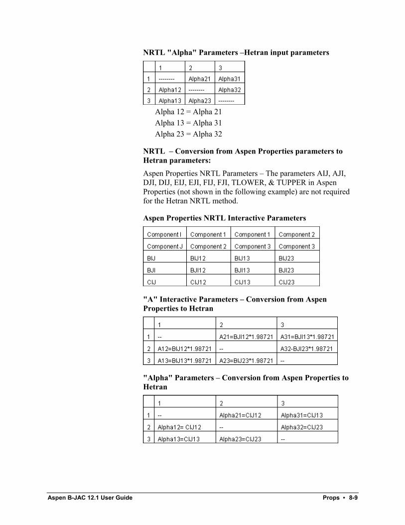
Aspen B-JAC 12.1 User Guide Props • 8-9
NRTL "Alpha" Parameters �Hetran input parameters
Alpha 12 = Alpha 21 Alpha 13 = Alpha 31 Alpha 23 = Alpha 32
NRTL � Conversion from Aspen Properties parameters to Hetran parameters: Aspen Properties NRTL Parameters � The parameters AIJ, AJI, DJI, DIJ, EIJ, EJI, FIJ, FJI, TLOWER, & TUPPER in Aspen Properties (not shown in the following example) are not required for the Hetran NRTL method.
Aspen Properties NRTL Interactive Parameters
"A" Interactive Parameters � Conversion from Aspen Properties to Hetran
"Alpha" Parameters � Conversion from Aspen Properties to Hetran

8-10 • Props Aspen B-JAC 12.1 User Guide
The NRTL method requires binary interaction parameters for each pair of components and an additional Alpha parameter. This data is not available from the databank.
The Uniquac method requires binary interaction parameters for each pair of components and also needs a surface parameter and volume parameter. This data is not available from the databank.
Results If you select this option, PROPS will display the following properties:
Specific Heat of a Liquid & Gas Latent Heat
Viscosity of Liquid & Gas Vapor Pressure
Thermal Conductivity of Liquid & Gas Surface Tension
Density of Liquid & Gas
If the VLE calculation was selected, Props will generate a vapor-liquid equilibrium curve and provide the: • Heat load • Composition • Physical properties per temperature increment
Props Logic The data in the databank is derived from a wide variety of published sources.
For constant properties, for example, molecular weight, the actual value has been stored in the databank.
For temperature dependent properties, various property specific equations are used to determine the property at the desired temperature. In these cases, the coefficients for the equation are stored in the databank.
Vapor pressures are stored using two equations - one for temperatures below the normal boiling point and one for temperatures above the normal boiling point.
There is a separate temperature range of validity stored in the databank for each property. The temperature range shown in the
NRTL - Alpha parameters
Uniquac - Surface & Volume parameters
Properties Over a Range of Temperatures
VLE
Databank Structure
Temperature Ranges

Aspen B-JAC 12.1 User Guide Props • 8-11
Databank Directory is the minimum range for all properties of the respective phase. Therefore, some properties may have a wider range than shown in the directory.
If you request a property at a temperature outside its valid temperature range, the program will display a warning and then determine that property at the appropriate temperature limit (i.e., it will not extrapolate), except for liquid viscosity and vapor pressure. The program extrapolates above and below the valid temperature range for vapor pressure. It extrapolates above for the liquid viscosity.
The program attempts to correct the gaseous properties as a function of pressure (liquid properties are assumed to be independent of pressure). To do this, the program uses a generalized correlation for all components except water/steam. The generalized correlation is reasonably accurate for most cases. However, it tends to deviate from actual measured values when the temperature or pressure approach the critical region.
For water (stored under the names WATER and STEAM), the program uses a series of specialized equations which predict the corrected steam properties to within 1% of the values in the ASME Steam Tables.
The Props program can calculate the composite properties for multicomponent mixtures for up to 50 components.
Some care should be taken in using the databank for mixtures. Some mixtures, such as immiscibles or binary mixtures where water is one of the components, do not conform to the equations. For this reason, some of the more common water solutions have been included in the databank as single components.
Mixtures are calculated according to the following techniques:
Density of Liquid
Latent Heat averaged in proportion to the weight percent
Molecular Volume
averaged in proportion to the mole percent
Effect of Pressure
Mixtures

8-12 • Props Aspen B-JAC 12.1 User Guide
Specific Heat of Gas
averaged in proportion to the weight percent
Specific Heat Liquid
averaged in proportion to the weight percent
Surface Tension averaged in proportion to the mole percent
Thermal Conductivity of Gas - Friend & Adler Equation
Thermal Conductivity of Liquid - averaged in proportion to the weight percent
Viscosity of Gas - Herning & Zipperer Equation
Viscosity of Liquid - Arrhenius Equation
Nomenclature:
µ =viscosity w=weight fraction M=molecular weight
k=thermal cond.
X=mole fraction I=i-th component
ρ=density y=gas phase mole fraction
m=mixture

Aspen B-JAC 12.1 User Guide Metals • 9-1
C H A P T E R 9
Metals
Input Use this sheet to specify: • Material name for required components • Temperature range for temperature dependent properties
For the material name you can use the generic material types, such as carbon steel (default), and the program will assign actual default material specifications depending on the product form. For carbon steel plate, a material specification of SA-516-70 will be used for an ASME design. Appropriate specifications will be selected for other design construction codes.
The selections to the right of the input field are provided for convenience. Values are not limited to those listed. To search for a specific material specification, click the Search Databank button. Type the first few characters to search for a material in the databank.
You can use the DefMats utility to change the default materials.
Many of the properties in the metals databank are temperature dependent. The starting and ending temperatures determine the temperature range. Either may be higher or lower. The program will retrieve properties beginning at the starting temperature, then incrementing the temperature by the temperature increment value until it reaches the ending temperature or a maximum of eleven points.
General Sheet

9-2 • Metals Aspen B-JAC 12.1 User Guide
Results The Metals program gives you the option of requesting properties at a single temperature or at up to ten temperatures. If you request properties at a single temperature you will also retrieve the properties which are not temperature dependent.
Aspen B-JAC provides an extensive system of warnings and messages to help the designer of heat exchanger design. Messages are divided into five types. There are several hundred messages built into the program. Those messages requiring further explanation are described here.
Warning Messages: These are conditions, which may be problems, however the program will continue.
Error Messages: Conditions which do not allow the program to continue.
Limit Messages: Conditions which go beyond the scope of the program.
Notes: Special conditions which you should be aware of.
Suggestions: Recommendations on how to improve the design.
Material Properties Property Value Price 31.75 USD/kg Density 4512 kg/m3 P No. 52 Group No. � Specified Min. Yield 379 MPa Specified Min. Tensile
448 MPa
Poisson Ratio 0.32 Material Class Titanium Alloy
This part of the output is self-explanatory. Where the property is not stored, or the temperature exceeds the acceptable range for the material, the program displays a dash.
Material Properties Property Value Price 44.09 USD/kg Density 2201 kg/m3 Gasket Factor m 2.75
Metals Results
Warnings & Messages
Properties Independent of Temperature
Properties Dependent on Temperature
Gasket Properties

Aspen B-JAC 12.1 User Guide Metals • 9-3
Property Value Min. Design Seating Stress y 25511 MPa Gasket Thickness 1.6 mm ASME Column 2
Metals Directory - ASTM - Generic Number Generic Material 1 Carbon Steel 2 Low Alloy Steel C 1/2 Mo 3 Low Alloy Steel 1/2 Cr 1/2 Mo 4 Low Alloy Steel Cr 1/2 Mo 5 Low Alloy Steel 1 1/4 Cr 1/2 Mo 6 High Alloy Steel Grade 304 7 High Alloy Steel Grade 304L 8 High Alloy Steel Grade 316 9 High Alloy Steel Grade 316L 10 High Alloy Steel Grade 347 11 High Alloy Steel Grade 310S 12 High Alloy Steel Grade 310S XM-27 (E-
brite) 13 High Alloy Steel Grade 410 14 Nickel Alloy 200 15 Nickel Low Carbon Alloy 201 16 Nickel Alloy 400 (Monel) 17 Nickel Alloy 600 (Inconel) 18 Nickel Alloy 800 19 Nickel Alloy 825 (Inconel 825) 20 Nickel Alloy B (Hastelloy B) 21 Nickel Alloy C (Hastelloy C) 22 Nickel Alloy G (Hastelloy G) 23 Nickel Alloy 20Cb (Carpenter 20) 24 Titanium 25 Copper-Nickel 70/30 Alloy CDA 715 26 Copper-Nickel 90/10 Alloy CDA 706 27 Copper-Nickel Alloy CDA 655 28 Naval Brass Alloy 464 29 Aluminum-Bronze Alloy 630 30 Aluminum Brass Alloy 687 31 Admiralty Alloy 443 33 Zirconium

9-4 • Metals Aspen B-JAC 12.1 User Guide
References For a further understanding of subjects relating to METALS, see the following publications
Material Properties ASME Boiler and Pressure Vessel Code, Section II, Materials, Part D Properties, annual
American National Standards Institute (ANSI)
Deutsches Institut für Normung e.V. (DIN)
AD-Merkblätter - Technical Rules for Pressure Vessels, Carl Heymanns Verlag KG, Berlin, Germany, annual
Verband der Technischen Überwachungs-Vereine e.V. (VdTÜV)
Association Française de Normalisation (AFNOR)
Standards of Tubular Exchangers Manufacturers Association, Seventh Edition, TEMA, New York, USA, 1988
Equivalent Materials Worldwide Guide to Equivalent Irons and Steels, ASM International, Metals Park, Ohio, USA, 1987
Worldwide Guide to Equivalent Nonferrous Metals and Alloys, ASM International, Metals Park, Ohio, USA, 1987
Stahlschlüssel, C. W. Wegst, Verlag Stahlschlüssel Wegst GmBH, Marbach, Germany,1992
Material Prices Metal Statistics - The Purchasing Guide of the Metal Industries, Fairchild Publications, New York, USA, annual
Metals References

Aspen B-JAC 12.1 User Guide Priprops • 10-1
C H A P T E R 10
Priprops
Introduction The Priprops program allows you to create your own chemical properties databank for those fluids not found in the B-JAC databank. By selecting the User databank when your private component is referenced in the B-JAC programs, the program will automatically access the private databank when the programs need to retrieve properties from the databank. The private databank can accommodate up to 400 different fluids.
Accessing the Priprops databank Accessing an existing component in the databank Access the Priprops program by selecting Data Maintenance | Chemical Databank under the Tools menu on the Menu Bar.
The user can view an existing B-JAC or Standard component in the databank by: • selecting B-JAC or Standard from the databank option menu, • then type in the component name, formula, B-JAC ID number,
or synonym, • if present the component will be shown with the stored
properties.
Adding a new component to Priprops Access the Priprops program by selecting Data Maintenance | Chemical Databank under the Tools menu on the Menu Bar.
To add a new private component to the databank: • select the User databank
10-2 • Priprops Aspen B-JAC 12.1 User Guide
• type the reference name that you wish to call the component • enter the required physical properties, constants, and curve
fitting data for the component • select the add button to add the new component to the database • select the Update button to save the new component and to
update the databank
Adding a new component using an existing component as a template: • select the B-JAC or Standard databank • search for similar component by typing in the name or
reference to locate the component • select the copy button to copy all the property information • return to the User databank • type in the name for the new component • select the Add button to add the component • select the Paste button to copy the properties from the standard
databank • modify as necessary the properties that differ from the standard
component • select the Update button to save the new component and to
update the databank
Property Reference Reference the Props section of this user guide for additional information on the components provided in the B-JAC and standard databanks.

Aspen B-JAC 12.1 User Guide Priprops • 10-3
Property Estimation Property Curves
Key Equation0 .... Y = C1 + C2 * T + C3 * T**2 + C4 * T**3 + C5 * T**41 .... Y = exp (C1 + C2 / T + C3 * ln(T) + C4 * T ** C5)2 .... Y = C1 * T ** C2 / (1 + C2 / T + C3 / T ** 2)3 .... Y = C1 + C2 * exp (-C3 / T ** C4)4 .... Y = C1 + C2 / T + C3 / T ** 3 + C4 / T ** 8 + C5 / T ** 95 .... Y = C1 / C2 ** (1 + (1 - T / C3) ** C4)6 .... Y = C1 * (1 - T / Tc) **
(C2 + C3 * ( T / Tc) + C4 * (T / Tc) ** 2 + C5 * ( T / Tc) ** 3)7 .... Y = C1 + C2 * ((C3 / T) / sinh (C3 / T)) ** 2 + C4 *
((C5 / T) / cosh (C5 / T)) ** 2C1,C2,C3,... CoefficientsT ... Input Temperature in K or RTc ... Critical Temperature in K or RY ... Calculated Value** ... Power Function
Property estimation based on NBP The physical properties program can estimate physical properties for hydrocarbon components based on their normal boiling point (NBP) and either the molecular weight or the degrees API. The estimated properties will be reasonably accurate for the hydrocarbons which meet the following criteria: 1 The normal boiling point is between 10 and 371 C (50 and 700
F). 2 The molecular weight is between 50 and 300. 3 The degrees API is between 5 and 120.
To specify the component name, use one of the following formats: • NBCxxxMWyyy where xxx is NBP in C and yyy is the
molecular weight • NBFxxxMWyyy where xxx is NBP in F and yyy is the
molecular weight • NBCxxxAPIyyy where xxx is NBP in C and yyy is the
degrees API • NBFxxxAPIyyy where xxx is NBP in F and yyy is the degrees
API
Examples: NBC113MW156 NBC98.4API40 NBF323MW70 NBF215.8API44.2
Components outside the ranges specified above will NOT be accepted.

10-4 • Priprops Aspen B-JAC 12.1 User Guide

Aspen B-JAC 12.1 User Guide Primetals • 11-1
C H A P T E R 11
Primetals
Introduction Primetal is a program that allows you to build and maintain your own databank of materials which supplements the materials in the Metals databank.
The material can be in the form of plate, pipe, tube, forging, coupling, bolt, or gasket. Once you assign a material name and store the material properties, you can then use the new material name in any of the Aspen B-JAC programs which allow specific material names (Hetran, Teams, Metals).
The Primetal program provides the following functions: • Add a material • Modify the properties of a material • Delete a material • Display or print a list of materials • Display or print the properties of a material
This program does not require an input data file, since all of the data is stored in the databank itself. You specify the input data directly into the Primetal program when you run it. The input data can be specified in either U.S., SI, or Metric units and is divided into three sections: • Names • Constant properties • Temperature dependent properties
The names are: • Full name (up to 78 characters)

11-2 • Primetals Aspen B-JAC 12.1 User Guide
• Short name (up to 39 characters) for the mechanical design output
• Very short name (up to 24 characters) for the bill of materials
The constant properties include: • Material type and class • Price and currency • Equivalent material numbers for pipe, plate, forging, coupling • Density • Minimum thickness • P number and group number • External pressure chart • Minimum tensile and yield strengths • Maximum thickness for x-ray exemption • Poisson ratio • Minimum and maximum diameter for validity
The temperature dependent properties include: • Thermal conductivity • Allowable stress • Yield strength • Coefficient of thermal expansion • Modulus of elasticity • Stress intensity • Tensile strength
For each of the temperature dependent properties, you can specify from 2 to 21 points, starting from a specified starting temperature, then according to a specified temperature increment. Each property should also have minimum and maximum temperatures. If a value is not available for one or more of the temperature points, you can specify a zero (or leave it blank) and the databank routine will automatically interpolate using the closest specified values.
This item refers to the currency of the values in the cost files. The original selections are:
1= $US 2= $Canadian 3= French Franc
4= British Pound
5= Belgium Franc
6= Deutch Mark
7= Italian Lire 8= Yen
The default values are already in US dollars. I recommend to always use 1 (US Dollar).
Currency
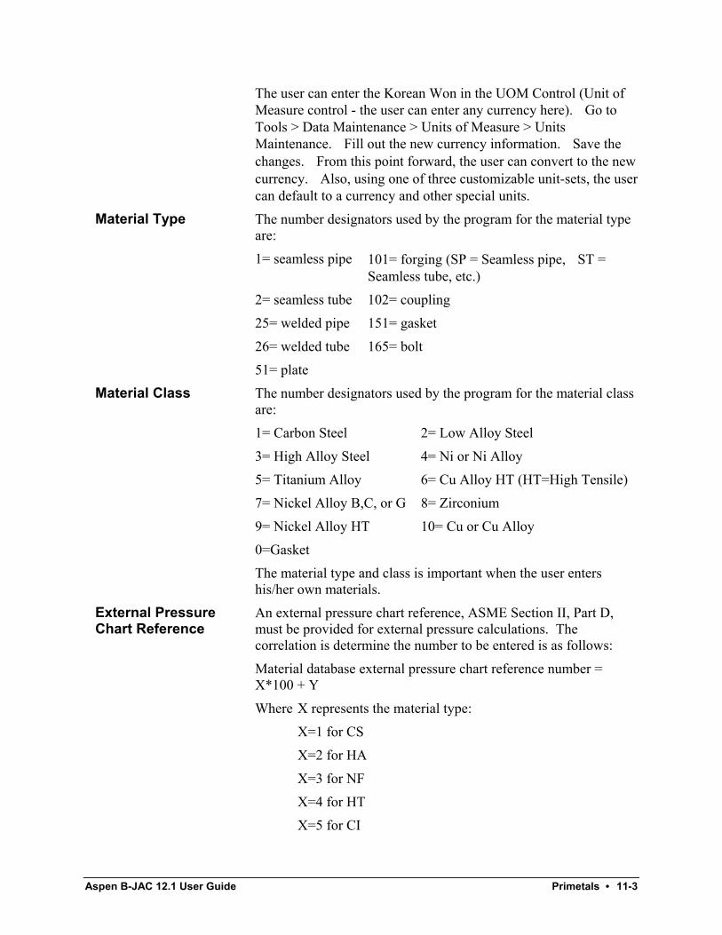
Aspen B-JAC 12.1 User Guide Primetals • 11-3
The user can enter the Korean Won in the UOM Control (Unit of Measure control - the user can enter any currency here). Go to Tools > Data Maintenance > Units of Measure > Units Maintenance. Fill out the new currency information. Save the changes. From this point forward, the user can convert to the new currency. Also, using one of three customizable unit-sets, the user can default to a currency and other special units.
The number designators used by the program for the material type are:
1= seamless pipe 101= forging (SP = Seamless pipe, ST = Seamless tube, etc.)
2= seamless tube 102= coupling
25= welded pipe 151= gasket
26= welded tube 165= bolt
51= plate
The number designators used by the program for the material class are:
1= Carbon Steel 2= Low Alloy Steel
3= High Alloy Steel 4= Ni or Ni Alloy
5= Titanium Alloy 6= Cu Alloy HT (HT=High Tensile)
7= Nickel Alloy B,C, or G 8= Zirconium
9= Nickel Alloy HT 10= Cu or Cu Alloy
0=Gasket
The material type and class is important when the user enters his/her own materials.
An external pressure chart reference, ASME Section II, Part D, must be provided for external pressure calculations. The correlation is determine the number to be entered is as follows:
Material database external pressure chart reference number = X*100 + Y
Where X represents the material type:
X=1 for CS
X=2 for HA
X=3 for NF
X=4 for HT
X=5 for CI
Material Type
Material Class
External Pressure Chart Reference
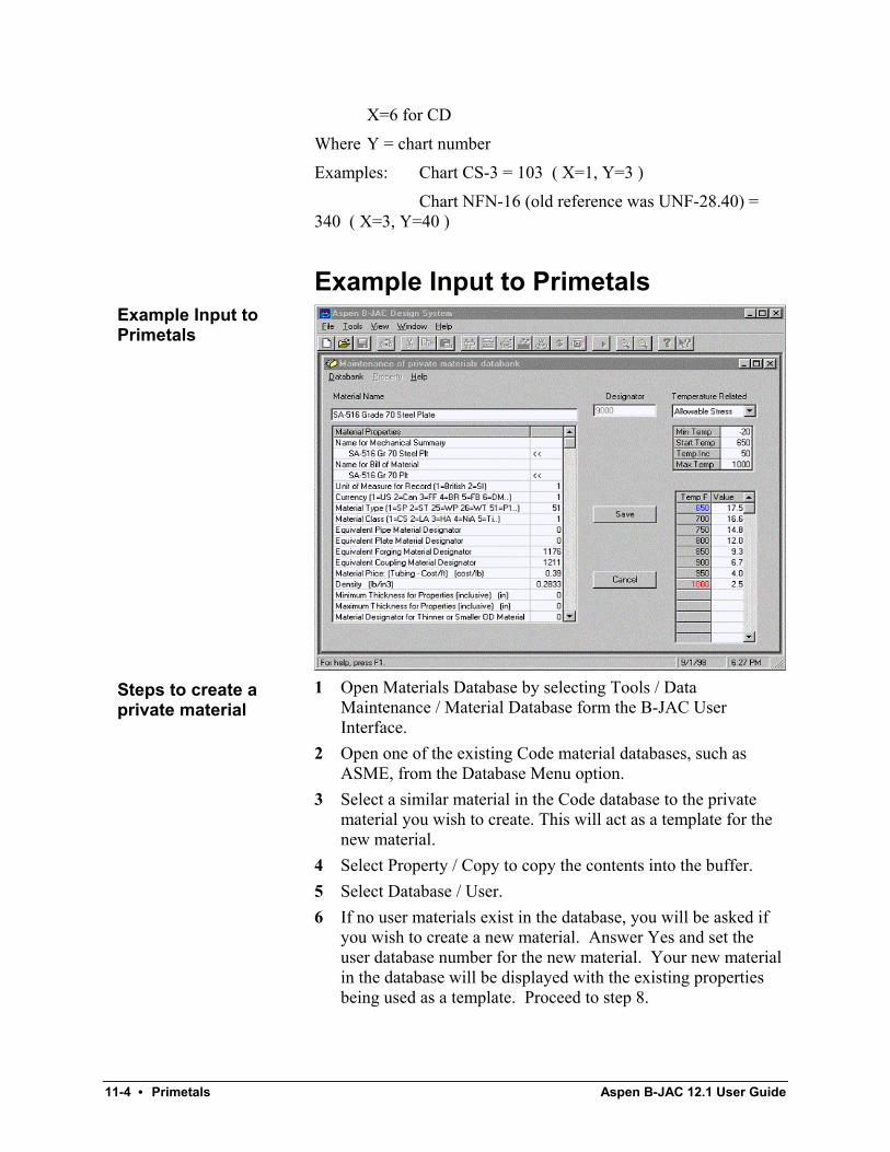
11-4 • Primetals Aspen B-JAC 12.1 User Guide
X=6 for CD
Where Y = chart number
Examples: Chart CS-3 = 103 ( X=1, Y=3 )
Chart NFN-16 (old reference was UNF-28.40) = 340 ( X=3, Y=40 )
Example Input to Primetals
1 Open Materials Database by selecting Tools / Data
Maintenance / Material Database form the B-JAC User Interface.
2 Open one of the existing Code material databases, such as ASME, from the Database Menu option.
3 Select a similar material in the Code database to the private material you wish to create. This will act as a template for the new material.
4 Select Property / Copy to copy the contents into the buffer. 5 Select Database / User. 6 If no user materials exist in the database, you will be asked if
you wish to create a new material. Answer Yes and set the user database number for the new material. Your new material in the database will be displayed with the existing properties being used as a template. Proceed to step 8.
Example Input to Primetals
Steps to create a private material

Aspen B-JAC 12.1 User Guide Primetals • 11-5
7 If user materials already exist, your existing database items will be displayed. To copy the template properties, select Property and Paste and then select a number new material reference number.
8 Now modify the template properties to generate your new material. If you have selected a very similar material, you may only need to modify the material names and the allowable design stresses.
9 Once all changes have been made, select Save to update the database. Now this new user material may be referenced from any of the B-JAC programs.

11-6 • Primetals Aspen B-JAC 12.1 User Guide
Aspen B-JAC 12.1 User Guide Newcost Database • 12-1
C H A P T E R 12
Newcost Database
Introduction Newcost is a database maintenance program, designed to modify and/or print the contents of the labor and material cost files associated with the Aspen B-JAC programs which address cost estimation (Teams, Qchex, and Hetran).
B-JAC supplies a standard database with each version of the program. When you make any changes to the database, your changes will always override any values in the standard database.
To start the Newcost database, first change your working directory to where you want the modified database to reside. This can be the same directory as the Aspen B-JAC programs or other user sub-directories. When you make changes using Newcost the changes are stored in your current directory. In this way you can build separate databases on different directories, which can reflect different costing requirements for different projects or bids. Access the Newcost program by selecting Tools from the Menu Bar and then selecting Data Maintenance and then selecting Costing.
The Newcost gives you access to these databases: 1 General cost and labor adjustment 2 Fabrication and operation standards 3 Material dependent fabrication standards 4 Welding standards 5 Labor efficiency factors 6 Material prices 7 Part numbers for bill of materials and drawings 8 Horizontal support standards

12-2 • Newcost Database Aspen B-JAC 12.1 User Guide
Labor & Cost Standards The Newcost database contains the following labor and cost standards.
This database contains the burdened labor rate (total cost per hour of labor), the markups on labor and material, and the overall efficiency factors for welding, machining, drilling, grinding, and assembly.
This section allows you to specify over 100 specific fabrication options which affect the mechanical design and/or the cost. In many cases these options will establish the defaults for the Teams program where "0 = program." Included are such things as minimum and maximum material dimensions (e.g. minimum thickness for nozzle reinforcement pads, minimum and maximum bolt diameter, and maximum length of pipe) and cost factors (e.g., cost of x-ray, stress relieving, skidding, and sandblasting). Also included are the system of measure and the money currency, which apply to all of the Newcost databases.
This file contains the fabrication variables which are dependent upon the type of material. The materials are divided into ten classes. It includes such items as machining and drilling speeds, weld deposition rates, maximum dimensions for various operations, and dimensional rounding factors.
Here you can specify the type of welding to be used for each type of vessel component made from each of ten different material classes. You can choose from stick electrode, self shielded flux core, gas metal arc, submerged arc, tungsten inert gas, and plasma welding.
The cost estimate routines use the data in this file to correct the number of hours for each labor operation for each type of component. The raw hours determined by the program are divided by the appropriate efficiency factor. For example, if the program calculates 20 hours to drill a tubesheet, and the efficiency factor is 0.5, the estimated number of hours will be 40 hours. The operations covered are layout, saw, shear, burn, bevel, drill, machine, mill, form, roll, weld, grind, and assemble.
This is the database which contains the prices for each material. Prices for most materials are price per unit weight (e.g. $/lb), except tubing which is price per unit length for a 19.05 mm (3/4") tube with a 1.65 mm (0.065") wall thickness. The standard Aspen B-JAC price is displayed. You can specify a price for any material, which will then override the standard Aspen B-JAC price.
General Cost and Labor Adjustment
Fabrication and Operation Standards
Material Dependent Fabrication Standards
Welding Standards
Labor Efficiency Factors
Material Prices

Aspen B-JAC 12.1 User Guide Newcost Database • 12-3
Default part numbers for every component are provided in this database. You can modify the default numbers as necessary.
You can customize the standard support dimensions used by the programs or use the default dimensions shown in the database.
Newcost Database Example Here is an example of the Newcost database in use:
Part numbers for bill of materials and drawings Horizontal support standard dimensions

12-4 • Newcost Database Aspen B-JAC 12.1 User Guide

Aspen B-JAC 12.1 User Guide Aspen B-JAC Example • 13-1
C H A P T E R 13
Aspen B-JAC Example
This example consists of the following sections: • The User Interface • General Specifications • Specifying Components • Completing Property Specifications • Specifying Geometry • Specifying Design Data • Running the Problem • Viewing the Results • Tuning the Design • Performing Mechanical Design • Specifying Geometry in Teams • Specifying Materials for Teams • Running Teams • Viewing Teams Results • Addressing Problems Discovered by Teams

13-2 • Aspen B-JAC Example Aspen B-JAC 12.1 User Guide
Aspen B-JAC Example: The User Interface
This is the Aspen B-JAC program window. Select File from the menu bar to open a new or existing file. For this example you will open an existing file to first perform a thermal design using Aspen Hetran and then transferring the information in the Aspen Teams program for a mechanical design. Operation of the Aspen Aerotran program is very similar to the Aspen Hetran program.

Aspen B-JAC 12.1 User Guide Aspen B-JAC Example • 13-3
On the left hand side of the window is the data browser to help you navigate through the program. The input and results sections are organized in a series of forms or folders. Each folder may contain multiple tabs to assist you through the program. For this Aspen Hetran file, select the Description section under Problem Definition. The units of measure are set at US. You can access the specific input folders by selecting a item on the navigator. As an alternate you can select the N (Next) button to help you navigate to the next required input item. Note that with the use of the Next button, the program will use default values for some design parameters.

13-4 • Aspen B-JAC Example Aspen B-JAC 12.1 User Guide
Aspen B-JAC Example: General Specifications
In this section provide the general equipment description and fluid titles that will appear on the heat exchanger data sheet and printed documentation.

Aspen B-JAC 12.1 User Guide Aspen B-JAC Example • 13-5
Applications for the hot side and cold side of the exchanger are then selected. This exchanger has a multi-component mixture condensing on the shell side and coolant on the tube side. The condensation curve will be specified by you from a process simulation run. The program will run in the Design Mode to optimize a size for the exchanger.
Now specify the process flow conditions for the hot and cold sides for the exchanger. At any point in the program you can obtain context sensitive Help by selecting the ? button and then selecting the input field that you need help on. You can also access the reference help for the subject by selecting the input field and then pressing F1. Input sections that are not complete will be identified by a red X on the navigator. Required input fields will be highlighted by a green background. Inputted valued which exceeds a normal range for that field will be highlighted in red. Note that if you still proceed with a value outside the normal range, the program will still use the inputted value.

13-6 • Aspen B-JAC Example Aspen B-JAC 12.1 User Guide
Physical property data for the streams may be supplied by the Aspen B-JAC Databank, the Aspen Properties Plus Databank, or you can input the properties. If you select the Aspen Plus Databank you must supply a APPDF interface file. For this example, you will be specifying the Aspen B-JAC Databank.

Aspen B-JAC 12.1 User Guide Aspen B-JAC Example • 13-7
Aspen B-JAC Example: Specifying Components
To reference the Aspen B-JAC Databank, specify each component of the stream in the Hot Side Composition section. Vapor in, liquid in, and liquid out flows are provided for each component. If a component is known to be a noncondensable or immiscible, it should be specified. You can access the Aspen B-JAC Databank listing by selecting the Search button.

13-8 • Aspen B-JAC Example Aspen B-JAC 12.1 User Guide
To search the Aspen B-JAC Databank for a compound, type in the component name or formula and the program will search the databank. Once located, you can select the Add key to add that component to the stream list to be referenced. Select OK to return to the composition form and the items selected will be added to the list.

Aspen B-JAC 12.1 User Guide Aspen B-JAC Example • 13-9
Aspen B-JAC Example: Completing Property Specifications
The VLE curve is specified in the Hot Side Properties section. Heat load may be provided as cumulative, incremental, or as enthalpy. Flowrate per increment may be specified by vapor/liquid flow rate or vapor/liquid mass fraction.

13-10 • Aspen B-JAC Example Aspen B-JAC 12.1 User Guide
Since you are referencing the Aspen B-JAC Databank, the liquid, vapor, and noncondensable properties will be retrieved from the databank.
The properties for the cooling water on the cold side will be retrieved from the Aspen B-JAC Property Databank. This completes the process data section of the Aspen Hetran input file. At this point you could proceed with the calculations allowing the program to set defaults for the mechanical design constraints. We will proceed through the mechanical section to review what has been specified for this exchanger.

Aspen B-JAC 12.1 User Guide Aspen B-JAC Example • 13-11
Aspen B-JAC Example: Specifying Geometry
Aspen Hetran supports all the TEMA type heads and shell configurations. For this item, a BEM type is selected. Each input field is select by clicking on the arrow in the appropriate box to see the drop down menu selections. You then select which option you want.

13-12 • Aspen B-JAC Example Aspen B-JAC 12.1 User Guide
You then provide the tubing requirements: type, diameter, and thickness. Many of the drop down menus are supported with diagrams which will assist you in you selection process, such as the tube pattern shown above. Note also the Prompt Area located at the bottom of the form which will provide additional information for many of the input fields.
For most applications, the Aspen Hetran program will default to single segmental baffles. The program will also select a baffle cut and baffle orientation based upon the application. If the shell pressure drop is controlling the design, you may want to change to a double or triple segmental type.
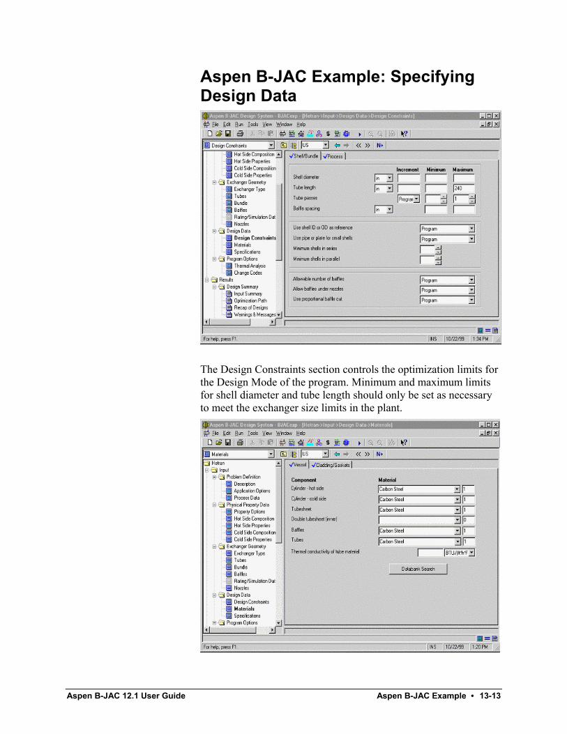
Aspen B-JAC 12.1 User Guide Aspen B-JAC Example • 13-13
Aspen B-JAC Example: Specifying Design Data
The Design Constraints section controls the optimization limits for the Design Mode of the program. Minimum and maximum limits for shell diameter and tube length should only be set as necessary to meet the exchanger size limits in the plant.

13-14 • Aspen B-JAC Example Aspen B-JAC 12.1 User Guide
The B-JAC Metals Databank provides a generic material list which allows to specify general classes of materials, such as carbon steel or 304 stainless steel. The program will then reference an appropriate material class for a specific pressure vessel component. You can search the Metals Databank by selecting the Search button.
By typing the material to be referenced, the program will search to find the material in the Databank. Once located, you can select the component and then the Set Key to select that material for that component. After all materials have been selected, click OK to return to the Material form and your selections will be inserted.

Aspen B-JAC 12.1 User Guide Aspen B-JAC Example • 13-15
Specify the applicable design code and standards for the unit. The Aspen Hetran program will estimate the design pressure and temperature for you based upon the operating conditions but it is recommended to provide these if known.
Aspen B-JAC Example: Running the Problem You have completed the input for the design. Select the Run command from the Menu Bar and then select to Run Hetran. As an alternate you can select the Run icon button located in the Tool Bar.

13-16 • Aspen B-JAC Example Aspen B-JAC 12.1 User Guide
The optimization path screen will appear. Hetran will first select an exchanger size which is close to compiling to the specification requirements. The program will then provide incremental results allowing you to see
Once the optimization is complete, you can display the final resulting design. First to be displayed are any warnings or notes. Note the heat load adjustment made by the program.

Aspen B-JAC 12.1 User Guide Aspen B-JAC Example • 13-17
Aspen B-JAC Example: Viewing Results
You can review the Performance Summary section. Process conditions, calculated film coefficients, pressure drops, and mechanical summary are provided.
Thermal Resistance Analysis includes three cases:

13-18 • Aspen B-JAC Example Aspen B-JAC 12.1 User Guide
• Clean • Spec. Foul • Max. Foul
The clean condition is expected performance assuming no fouling exists in the exchanger. For this case the exchanger is 87.7% oversurfaced in the clean condition. The Spec. Foul case shows a 7.71% excess surface area based upon the designed conditions. The last case, Max. Foul, uses all the excess surface area, the 7.71%, and translates this to additional fouling available. Fouling factors are increased to .0012 and .0024.
Hetran, for a multiphase application, will calculate separate film coefficients for the vapor, liquid, and condensing present. For this condenser, a condensing film of 313.25 is weighted with the liquid cooling film for an overall film coefficient of 310.38.

Aspen B-JAC 12.1 User Guide Aspen B-JAC Example • 13-19
The pressure drop distribution summary will help you determine if adjustments need to be made in nozzle sizes and/or baffling to re-distribute pressure loss and enhance heat transfer in the tube bundle.
A shell side stream analysis and mass velocity summaries are provided.

13-20 • Aspen B-JAC Example Aspen B-JAC 12.1 User Guide
To view the exchanger data sheet, select the TEMA Sheet in the navigator. Use the slide bars to view the balance of the data sheet.
A scaled outline drawing is provided so you can view the nozzle and baffle arrangements for the exchanger design.

Aspen B-JAC 12.1 User Guide Aspen B-JAC Example • 13-21
Also provided is a scaled tube layout drawing showing the location of the tubes, baffle cuts, tie rods, and nozzles.
To view the detail calculations, select the Interval Analysis sections. This section provide a results for each thermal interval analyzed by the program. Viewed above is the Performance section heat loads, overall coefficients, areas, and pressure drops for each increment.

13-22 • Aspen B-JAC Example Aspen B-JAC 12.1 User Guide
This section provides the incremental film coefficients.
The heat load incremental analysis is also provided.

Aspen B-JAC 12.1 User Guide Aspen B-JAC Example • 13-23
Aspen B-JAC Example: Tuning the Design
Now let us consider that the controlling design optimization parameter was the tube length. Select Design Constraints in the Navigator and change the maximum tube length to 288 inches from the original 240 inches. Select the Run button and have Aspen Hetran re-optimize the design with the longer allowable tube length.

13-24 • Aspen B-JAC Example Aspen B-JAC 12.1 User Guide
The optimization summary shows that the exchanger size and cost was reduced.
In the results section, select the Recap of Designs in the Navigator to view the comparison summary of the original design and the new design. By following these steps, you can possibly make further improvements to the design by making adjustments and having Aspen Hetran re-optimize. We have complete the thermal
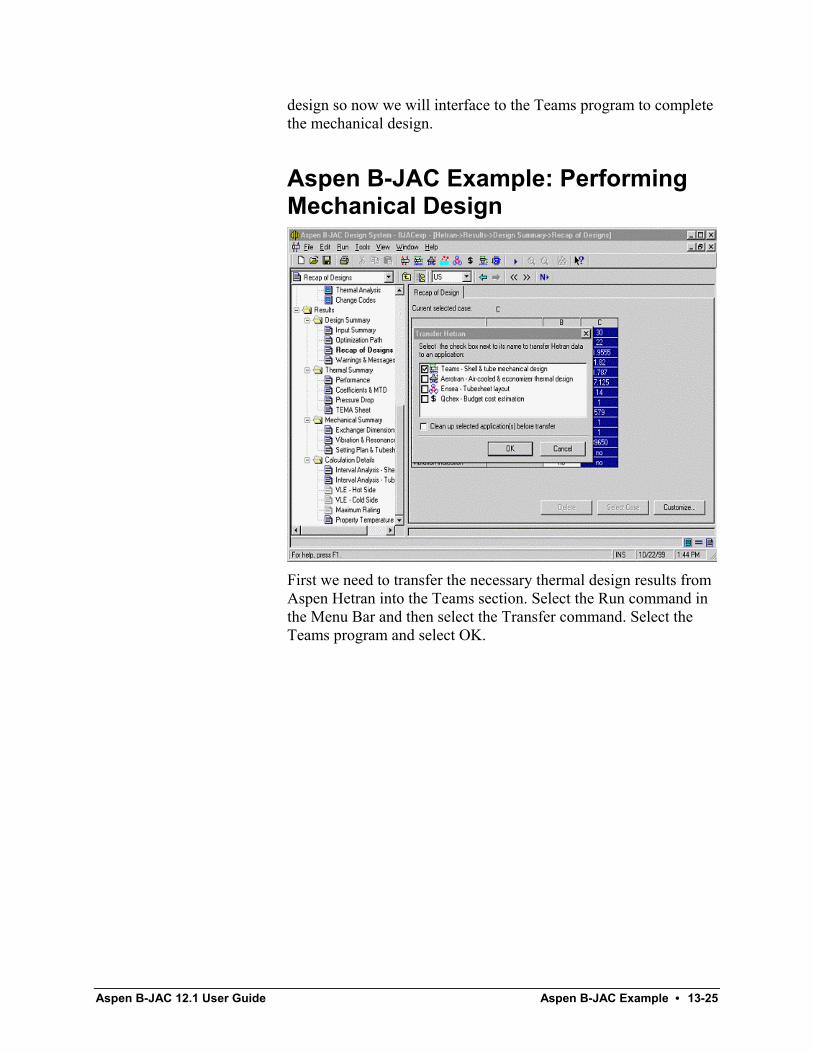
Aspen B-JAC 12.1 User Guide Aspen B-JAC Example • 13-25
design so now we will interface to the Teams program to complete the mechanical design.
Aspen B-JAC Example: Performing Mechanical Design
First we need to transfer the necessary thermal design results from Aspen Hetran into the Teams section. Select the Run command in the Menu Bar and then select the Transfer command. Select the Teams program and select OK.

13-26 • Aspen B-JAC Example Aspen B-JAC 12.1 User Guide
Specify the applicable code: ASME, Codap, or ADM. By selecting the TEMA class, default settings for flange design, corrosion allowance, and clearance will be set in accordance to the respective TEMA class.
Appropriate design conditions have been entered. Note that each input field has it own unique units control. You can enter any set of units by selecting the unit set required beside the input field. If you

Aspen B-JAC 12.1 User Guide Aspen B-JAC Example • 13-27
wish to convert to a different set of units, select the desired units and the value in the field will be converted.
Aspen B-JAC Example: Specifying Geometry in Teams
Teams has specific defaults set for each TEMA head type. For example the selected B type head will default to the ellipsoidal cover shown unless a different cover is specified. Defaults follow typical TEMA conventions. If you are rating an existing exchanger for a new set of design conditions, select the Detail Cylinder and Detail Cover tabs and enter the dimensions of the existing equipment. You can enter details for other components in a similar way.
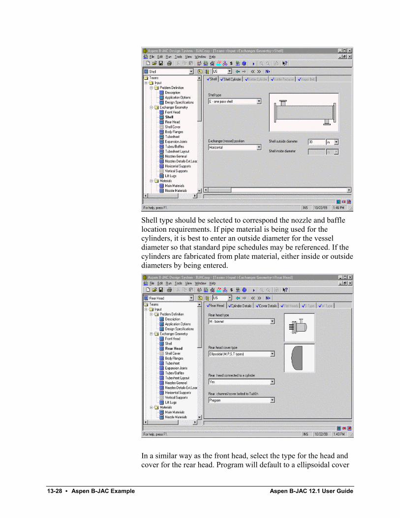
13-28 • Aspen B-JAC Example Aspen B-JAC 12.1 User Guide
Shell type should be selected to correspond the nozzle and baffle location requirements. If pipe material is being used for the cylinders, it is best to enter an outside diameter for the vessel diameter so that standard pipe schedules may be referenced. If the cylinders are fabricated from plate material, either inside or outside diameters by being entered.
In a similar way as the front head, select the type for the head and cover for the rear head. Program will default to a ellipsoidal cover

Aspen B-JAC 12.1 User Guide Aspen B-JAC Example • 13-29
unless you specify one of the alternate types. If the exchanger is a one pass unit with a nozzle located in the rear head, specify that a rear head cylinder is to be provided.
Teams will default to a hub type body flanges for a TEMA Class R exchanger. NO flanges will be specified for the shell side since this example has the tube sheet extended for bolting to the head flanges. If you need to control individual flange specifications go to the Individual Standards tab in this form. For check rating existing flange designs, enter the actual flange size by selecting the Dimensions tab.

13-30 • Aspen B-JAC Example Aspen B-JAC 12.1 User Guide
Due to the relative high design pressure on the shell side, an expanded and seal weld tube joint has been specified. The program default is to extend the tubesheet for bolting to the heads for our BEM example.
Teams will check to see if an expansion joint is required and will provide one, if necessary, if you specify by program. In this example, an expansion joint has been specified. Accurate mean

Aspen B-JAC 12.1 User Guide Aspen B-JAC Example • 13-31
metal temperatures are required to properly analyze the expansion joint/tubesheet design.
The tubing requirements are inputted. If low fin tubes are required, provide the fin density, height, and thickness.

13-32 • Aspen B-JAC Example Aspen B-JAC 12.1 User Guide
Baffle type and baffle cut orientation are specified. Enter baffle cut, number of baffles, and baffle spacings in the Baffle Details tab form.
Tubesheet layout information is provided. Teams will default to TEMA requirements if you allow the program to select. Tube pass layout type was passed into TEAMS from the Aspen Hetran results. If not specified, the program will select the layout type to provide the maximum number of tubes possible.

Aspen B-JAC 12.1 User Guide Aspen B-JAC Example • 13-33
You can set the global information for the shell side and tube side nozzles. To set specific information for each nozzle, select the Nozzles-Details section in the Navigator.
Select the Nozzles Tab to provide nominal nozzle diameters and approximate nozzle zone locations. For nozzles located in the front/rear head covers, specify zones 1 or 9 and an angle of 360 degrees. For hill side nozzles, specify any angle other than multiples of 45 degrees.

13-34 • Aspen B-JAC Example Aspen B-JAC 12.1 User Guide
Saddle support zone locations are set.
Aspen B-JAC Example: Specifying Materials for Teams

Aspen B-JAC 12.1 User Guide Aspen B-JAC Example • 13-35
For this design, Hetran passed into Teams the generic material for all the components. Teams will then use the material properties for an appropriate material specification for each component. For example, the program will use SA-516-70 for the carbon steel tubesheet since ASTM standards were referenced. If you wish to specify actual material specifications, select the Search Databank button.
The Metals search window will then be shown. Enter the material name in the top input field and the program will search for a match. Select the desired material in the list. The next step is to select the component in the component list and then select the Set button to set the material to that component. Continue this process until the materials are selected for all the components. Nozzle materials are set in a similar method located under Nozzle Materials in the Navigator.
The Teams input file is now complete and the next step is to run the program.

13-36 • Aspen B-JAC Example Aspen B-JAC 12.1 User Guide
Aspen B-JAC Example: Running Teams
Select the Run command in the Menu Bar, then select Run Teams. The Run Teams options are: calculations only, calculations plus cost estimate, calculations plus drawings, or calculations plus cost plus drawings. As an alternative, the Run icon can be selected in the Tools Bar which will run calculations plus cost estimate and plus drawings.
The Program Status window will appear to provide you with a run status.
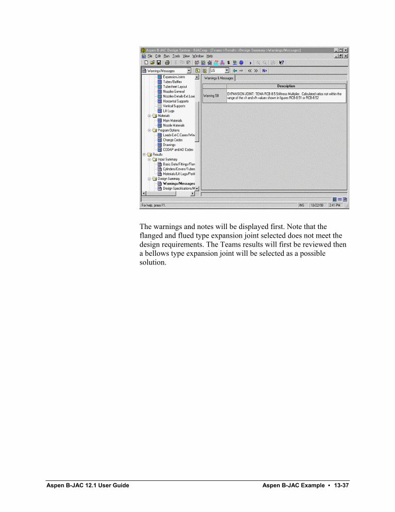
Aspen B-JAC 12.1 User Guide Aspen B-JAC Example • 13-37
The warnings and notes will be displayed first. Note that the flanged and flued type expansion joint selected does not meet the design requirements. The Teams results will first be reviewed then a bellows type expansion joint will be selected as a possible solution.

13-38 • Aspen B-JAC Example Aspen B-JAC 12.1 User Guide
Aspen B-JAC Example: Viewing Teams Results
The Teams results are organized in two five major sections: • Design Summary • Vessel Dimensions • Price • Drawings • Code Calculations
The Design Specification sections is shown here.

Aspen B-JAC 12.1 User Guide Aspen B-JAC Example • 13-39
The limiting MAWP components are shown in the above summary. The MAWP for the tubesheets are limited to the specified design conditions. To review the MDMT results, select the MDMT tab.
Select the Cylinders/Covers/Belts to review the cylinder results summary.

13-40 • Aspen B-JAC Example Aspen B-JAC 12.1 User Guide
Calculation results for the body flanges are shown above.
Teams provides results per the TEMA method and per the applicable selected code method. The program will use the thicker of the two methods.

Aspen B-JAC 12.1 User Guide Aspen B-JAC Example • 13-41
The cost estimate is based upon the Teams design code calculation results and the manufacture settings. The manufacturing standards are accessed by selecting Tools from the Menu Bar, selecting Data Maintenance, and then selecting Costing.
The scaled outline drawing can be viewed by selecting Setting Plan in the navigator. To view a specific area of the drawing, window the section of the drawing to be viewed. Select View command in the Menu Bar and then select Zoom In. As an alternative, use the
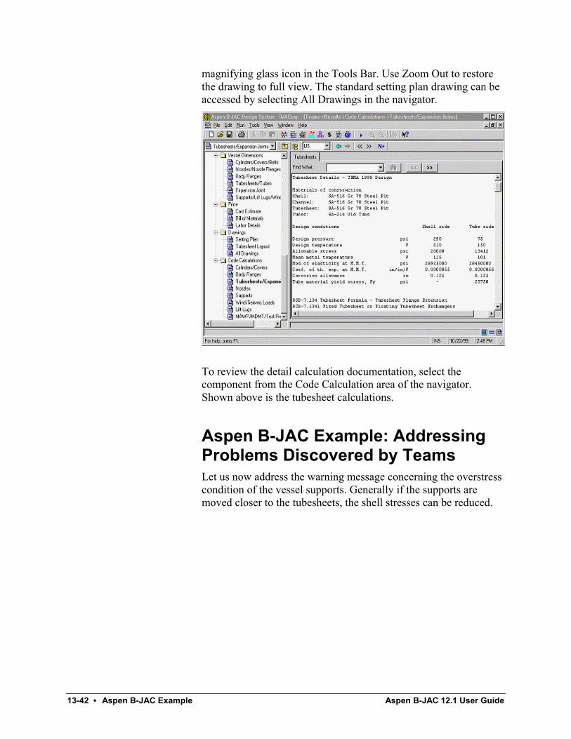
13-42 • Aspen B-JAC Example Aspen B-JAC 12.1 User Guide
magnifying glass icon in the Tools Bar. Use Zoom Out to restore the drawing to full view. The standard setting plan drawing can be accessed by selecting All Drawings in the navigator.
To review the detail calculation documentation, select the component from the Code Calculation area of the navigator. Shown above is the tubesheet calculations.
Aspen B-JAC Example: Addressing Problems Discovered by Teams Let us now address the warning message concerning the overstress condition of the vessel supports. Generally if the supports are moved closer to the tubesheets, the shell stresses can be reduced.

Aspen B-JAC 12.1 User Guide Aspen B-JAC Example • 13-43
Change the flanged and flued expansion joint type to bellow type.
Re-run the Teams calculations.

13-44 • Aspen B-JAC Example Aspen B-JAC 12.1 User Guide
Review of the warnings/notes shows that the expansion joint problem has been resolved by using the bellows type. Other adjustments to the design may done in a similar sequence by making changes and re-running Teams.
This completes our mechanical design for the heat exchanger.

Aspen B-JAC 12.1 User Guide Exporting Results from B-JAC to Excel • 14-1
C H A P T E R 14
Exporting Results from B-JAC to Excel
Introduction The Aspen B-JAC Windows user interface is designed to allow you to export input and results information into an Excel spread sheet.
This chapter describes how to use these export features. Topics include: • Export features • Exporting results to an existing spread sheet template • Creating your own customized template • Copying and pasting input and results from a B-JAC
application to Excel • Copying and pasting drawings to Excel • Launching a B-JAC application from Excel
Export Features You can export the program results to an Excel spreadsheet. Several Excel spreadsheet templates have been provided for your use. You can select one of the pre-formatted output summaries such as TeamsSummary.xlt or you can select one of the blank templates such as HetranBlank.xlt and customize your output in Excel.
B-JAC Templates

14-2 • Exporting Results from B-JAC to Excel Aspen B-JAC 12.1 User Guide
File / Export function - spread sheet created without Excel being open:
First open the B-JAC program window and open an exchanger design file, *.BJT. If no results are present, run B-JAC to obtain results. Select the "File / Export to" functions from the Menu Bar. Select to open the default template or you can specify which template to open. You can set the default template from the "Tools / Program Settings / Template" window. If you are selecting which template to open, select from the template list, HetranSummary, TeamsSummary, AerotranSummary or your customized template, located in the BJAC10\DAT\Template sub-directory. Select to open the template. Then provide a file name to save the results as a spread sheet *.xls data file. Results for the B-JAC design file will be now be saved in the created Excel spreadsheet.
First open the B-JAC program window and open an exchanger design file, *.BJT. If no results are present, run B-JAC to obtain results. Open Excel and then open the desired Excel template, HetranSummary, TeamsSummary, AerotranSummary, or your own customized template, located in the BJAC10\DAT\Template sub-directory. For information on how to create your own customized template, see the next section. Enable the macros. Results for the B-JAC design file will be shown in the Excel spreadsheet. If you wish to save these results as *.xls file, use the File / Save function in Excel.
To create you own customized Excel spreadsheet for the results from B-JAC, first make a copy of the *Blank.xlt template located in the BJAC10\DAT\Template sub-directory and rename it to use as your template for the customized results form. Open this new template in Excel. Enable the macros. Now by selecting various sections of the output results in B-JAC you can drag and drop into your template. You can change what information is moved from B-JAC by clicking on the right hand mouse button and selecting Drag-Drop format. You can select to drag-drop the value or units of measure only or to drag-drop the Caption, value, and units. For more information on customizing the spreadsheet in Excel, access Help provided in Excel. Once your customized template is complete and saved, every time B-JAC is run you can open your customized template to review the results from the run.
Exporting results to a B-JAC standard summary template or your customized template
Spread sheet created with Excel open
Creating your own customized Template

Aspen B-JAC 12.1 User Guide Exporting Results from B-JAC to Excel • 14-3
Copying Data from a B-JAC Application to Excel First you need to set the format for the copy. By default, the Drag-Drop function copies only the value (or values) of information. To reset the format, select Tools/Program Settings/Advanced and set the copy format. • Value only • Value and units of measure • Caption, value ands units of measure • Units of measure only
Select (or highlight) the information you wish to copy by clicking and holding down the left mouse button on the value and then dragging the mouse cursor to the desired location in the spread sheet. This �drag & drop" method will move the value as was as any caption and units you have set in the format described above.
Select (or highlight) the column of information you wish to copy by clicking and holding down the left mouse button on any value in the column and then dragging the mouse cursor to the desired location in the spread sheet. This �drag & drop" method will move the entire column of information as was as any caption and units that you have set to be copied in the format settings.
Select (or highlight) the table you wish to copy. Select the Edit / Copy function in the Menu Bar. Select the location for the table in the spread sheet. Select the Edit / Paste function from the Menu Bar in Excel to paste the table into the spread sheet. This copy & paste method will move the entire table of information as was as any caption and units that you have set to be copied in the format settings.
Select the drawing you wish to copy by clicking and holding down the left mouse button on the drawing then dragging the mouse cursor to the desired location in the spread sheet. This �drag & drop" method will move the drawing with border into the spread sheet.
This example shows the steps necessary to paste a column of information from the Interval Analysis Performance in the Aspen Hetran results into an Excel spreadsheet. • Open the B-JAC program window and select a Hetran file. If
results are not present, run the file. • Open Excel and open the HetranBlank.xlt template. Save as a
different template name.
Copy Format:
Copying Individual fields:
Copying Columns of information:
Copying Tables of information:
Copying drawings:
Example of Pasting Aspen B-JAC results into Excel.

14-4 • Exporting Results from B-JAC to Excel Aspen B-JAC 12.1 User Guide
• Locate the Overall Coefficient column in the Interval Analysis / Performance section of Hetran.
• Set the format for the copy to caption, values, and units under
Tools/Program settings/Advanced as described above in the Copy Format instructions.
• Using the mouse click on the Overall coefficient column with the left mouse button an hold the button down. Now drag the mouse cursor to the desired location in your Excel spread sheet and release the mouse button.

Aspen B-JAC 12.1 User Guide Exporting Results from B-JAC to Excel • 14-5
Launching B-JAC Programs from Excel Once you have created you own Excel spread sheet, it is possible to launch the B-JAC programs from within the spread sheet. To run a B-JAC program from within Excel, select Aspen B-JAC / Run from the Excel menu bar. Input design parameters may be changed within Excel and the results in the B-JAC program and in the spread sheet will reflect these changes.

14-6 • Exporting Results from B-JAC to Excel Aspen B-JAC 12.1 User Guide

Aspen B-JAC 12.1 User Guide Using the Aspen B-JAC ActiveX Automation Server • 15-1
C H A P T E R 15
Using the Aspen B-JAC ActiveX Automation Server
Introduction This chapter describes how to use the ASPEN B-JAC ActiveX Automation Server. The topics include: • About the Automation Server • Viewing the ASPEN B-JAC objects. • Overview of the ASPEN B-JAC objects • Programming with the ASPEN B-JAC objects • Reference information
This chapter assumes that you are familiar with Microsoft Visual Basic and understand the concepts of object-orientated programming.
The examples in this chapter use Visual Basic 5.0 and Visual Basic for Application (VBA) as the Automation Client. Much of the code examples in this chapter are taken from the example files, which are distributed with the standard ASPEN B-JAC installation. If you installed ASPEN B-JAC in the default location, the code examples are located in the Program Files\AspenTech\BJAC101\xmp\VB.
The examples use the example problem file LiquidLiquid.BJT, which is provided with the standard ASPEN B-JAC installation. You will find this file in Program Files\AspenTech\BJAC101\xmp if you installed ASPEN B-JAC in the default location.

15-2 • Using the Aspen B-JAC ActiveX Automation Server Aspen B-JAC 12.1 User Guide
About the Automation Server The ASPEN B-JAC Windows user interface is an ActiveX Automation Server. The ActiveX technology (formally called OLE Automation) enables an external Windows application to interact with ASPEN B-JAC through a programming interface using a language such Microsoft�s Visual Basic. The server exposes objects through the Common Object Model (COM).
With the Automation Server, you can: • connect both the inputs and the results of the ASPEN B-JAC
program to other applications such as design programs of databases.
• write your own user interface to control the ASPEN B-JAC program from creating a new application to printing results of the calculation. With your own interfaces you can use the ASPEN B-JAC program as a model for your design plan or use the ASPEN B-JAC program as a part of your design system.
Using the Automation Server In order to use the ASPEN B-JAC Automation Server, you must: • Have ASPEN B-JAC installed on your PC. • Be licensed to use ASPEN B-JAC.
The ASPEN B-JAC Automation Server consists of its principal component BJACWIN.EXE, the core component AtvCoreComponents.DLL and other supporting components.
The principal component, BJACWIN.EXE, is an out-of-process component, or ActiveX EXE. You will use this component to deal with ASPEN B-JAC documents and applications such as Hetran. The core component, ATVDataServer.DLL, is an in-process component, or ActiveX DLL. You will use this component to access application objects and data objects. The supporting components consist of several DLLs and OCXs and are intended to be for internal use only. If you installed the program in the default location, you will find those files in the Program File\AspenTech\BJAC101\xeq.
If you access ASPEN B-JAC objects using strongly typed declaration, you must reference the ASPEN B-JAC Automation Server in your project before you access the objects in your program.
To reference the ASPEN B-JAC Automation Server from Visual Basic, or Excel, open the References dialog box, and check the

Aspen B-JAC 12.1 User Guide Using the Aspen B-JAC ActiveX Automation Server • 15-3
ASPEN B-JAC Design System box and ATV core component box as shown here:
If ASPEN B-JAC Design System or ATV core component does not exist in the list, click Browse and find the ASPEN B-JAC executable directory. Select BJACWIN.EXE or ATVDataServer.DLL.
If you opened a project used earlier version of the ASPEN B-JAC or the Excel example file for the ASPEN Hetran, HETRANAUTO.XLS, you might find missing components in your project. In order to use the ASPEN B-JAC objects you should open the Reference dialog box and check the ASPEN B-JAC Design System box or the ATV core component box as mentioned earlier.
One object can not be destroyed unless all of the references to the object are released. Therefore, it is a good practice that you always release the objects you have referenced when the objects are no longer needed. Releasing an object is a simple task. This can be done by setting the object to Nothing.
As a general rule, you should release the objects in the opposite sequence as the objects are referenced. For example: Dim objBjac As ObjectDim objApp As Object‘ References objectsSet objBjac = CreateObject("BJACWIN.BJACApp")Set objApp = objBjac.LoadApp("Hetran"). . .
Releasing Objects

15-4 • Using the Aspen B-JAC ActiveX Automation Server Aspen B-JAC 12.1 User Guide
‘ Release objectsSet objApp = NothingSet objBjac = Nothing
Errors may occur in calling methods or accessing properties of the ASPEN B-JAC objects. It is important to create an error handler for all code, which accesses an automation interface. An automation interface may return a dispatch error for many reasons, most of which do not indicate fatal or even serious errors.
Although any error will normally causes a dialog box to be displayed on the user�s screen, it is strongly recommended that you write your own error handler to trap the error in order to exit the application cleanly or proceed with the next step.
Viewing the Aspen B-JAC Objects The detailed description of the ASPEN B-JAC objects, including properties, methods and named constants, may be viewed in the Automation Client Object Browser.
To use the browser, in Visual Basic and Excel, from the View menu, click Object Browser, the Object Browser will be displayed as shown here:
Error Handling

Aspen B-JAC 12.1 User Guide Using the Aspen B-JAC ActiveX Automation Server • 15-5
Overview of the Aspen B-JAC Objects The object exposed by ASPEN B-JAC Automation Server is the BJACApp object. Through this object other objects and their properties and methods may be accessed.
The following diagram provides a graphical overview of the ASPEN B-JAC object model:
Exposed by BJACWIN.EXE
Exposed by AtvDataServer.DLL
BJACApp ( The ASPEN B-JAC client object)
ATVApps ( Application object collection )
ATVApp ( Application object )
ATVArrays ( Array data objects collection )
ATVArray ( Array data object )
ATVScalars ( Scalar data objects collection )
ATVScalar ( Scalar data object )
The BJACApp object is the principal object exposed by ASPEN B-JAC. This object provides methods and properties such as: • Creating a new or opening an existing ASPEN B-JAC file • Creating a new or getting an existing ATVApp object • Controlling the default settings of the ASPEN B-JAC Window • Enumerating ATVApp objects • Printing results • Saving a file
For more information about the BJACApp object refer to the Reference Information section.
Object Model Diagram
The BJACApp Object
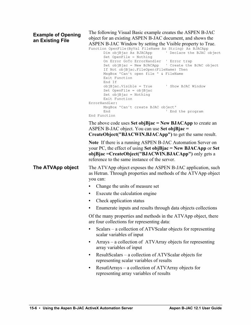
15-6 • Using the Aspen B-JAC ActiveX Automation Server Aspen B-JAC 12.1 User Guide
The following Visual Basic example creates the ASPEN B-JAC object for an existing ASPEN B-JAC document, and shows the ASPEN B-JAC Window by setting the Visible property to True. Function OpenFile(ByVal FileName As String) As BJACApp
Dim objBjac As BJACApp ' Declare the BJAC objectSet OpenFile = NothingOn Error GoTo ErrorHandler ' Error trapSet objBjac = New BJACApp ' Create the BJAC objectIf Not objBjac.FileOpen(FileName) ThenMsgBox "Can't open file " & FileNameExit FunctionEnd IfobjBjac.Visible = True ' Show BJAC WindowSet OpenFile = objBjacSet objBjac = NothingExit Function
ErrorHandler:MsgBox "Can't create BJAC object"End ' End the program
End Function
The above code uses Set objBjac = New BJACApp to create an ASPEN B-JAC object. You can use Set objBjac = CreateObject("BJACWIN.BJACApp") to get the same result.
Note If there is a running ASPEN B-JAC Automation Server on your PC, the effect of using Set objBjac = New BJACApp or Set objBjac =CreateObject("BJACWIN.BJACApp") only gets a reference to the same instance of the server.
The ATVApp object exposes the ASPEN B-JAC application, such as Hetran. Through properties and methods of the ATVApp object you can: • Change the units of measure set • Execute the calculation engine • Check application status • Enumerate inputs and results through data objects collections
Of the many properties and methods in the ATVApp object, there are four collections for representing data: • Scalars � a collection of ATVScalar objects for representing
scalar variables of input • Arrays � a collection of ATVArray objects for representing
array variables of input • ResultScalars � a collection of ATVScalar objects for
representing scalar variables of results • ResutlArrays � a collection of ATVArray objects for
representing array variables of results
Example of Opening an Existing File
The ATVApp object

Aspen B-JAC 12.1 User Guide Using the Aspen B-JAC ActiveX Automation Server • 15-7
Those data collections provide a bridge to allow you to manipulate data in the application including changing the units of measure, modifying the value and so on.
For more information about the ATVApp object refer to the Reference Information section.
The following Visual Basic example shows how to get the ASPEN B-JAC Hetran object from the BJACApp object by opening an existing file, checking the input status and launching the calculation engine.
Sub AccessHetran()Dim objBjac As BJACApp ' Declare a BJAC objectDim objHetran As ATVApp ' Declare a ATVApp objectDim nRetCode As Integer
On Error Resume Next ' Error trap
' We try to get a BJACApp objectSet objBjac = New BJACAppIf Err.Number <> 0 Then
MsgBox "Can't create BJACApp object!"End
End If
' First, we check to see if Hetran object is alreay there' in case there is a BJACApp object running and' Hetran object is created.
If objBjac.Hetran Is Nothing Then
' If no Hetran object in the current BJACApp object' then we open the sample file to get a Hetran object
If Not objBjac.FileOpen( _"C:\Program Files\AspenTech\BJAC10\xmp\LiquidLiquid.BJT") ThenMsgBox "Can't open the file."GoTo ExitThisSub
End IfEnd If
' Get the reference to HeatranSet objHetran = objBjac.GetApp("Hetran")
' Notice that this time we use method GetApp' to get Hetran object. You can use' Set objHetran = objBjac.Hetran' or' Set objHetran = objBjac.ATVApps("Hetran")
' Check to see if Hetran object is loaded' this time.
If objHetran Is Nothing ThenMsgBox "Hetran is not created."GoTo ExitThisSub
End If
' We change the units of measure to SIobjHetran.UomSet = ATV_UOMSET_SI
' Check to see if you can run HetranIf objHetran.CanRun() Then
' If yes, run Hetran and get the return codenRetCode = objHetran.Run()
Example of using an ATVApp object

15-8 • Using the Aspen B-JAC ActiveX Automation Server Aspen B-JAC 12.1 User Guide
' if we got any errorIf nRetCode <> 0 Then
MsgBox "Error in Hetran calculation. Code=" & nRetCodeEnd If
End If
' Release objectsExitThisSub:
Set objHetran = NothingSet objBjac = Nothing
End Sub
The ATVScalar object and the ATVArray object are used to represent data in the ASPEN B-JAC objects. As mentioned earlier, the ATVScalar object is used for scalar data and the ATVArray is used for array data. The ATVApp uses two pairs of collections containing ATVScalar objets and ATVArray objects to represent inputs and results, respectively. By accessing the properties and methods of the data objects, you can: • Return or set a value • Change the units of measure if the data is a physical quantity • Check the status of the variable
For more information about programming with the ATVScalar object and ATVArray object is provided in the Programming with the ASPEN B-JAC Objects section. Detailed reference information about the ATVScalar object and ATVArray object is provided in the Reference Information section.
The following Visual Basic example shows how to access a scalar input variable, change its units of measure and value, and how to retrieve an array data from results. Note that the example code is stored in the prjAccessData.VBP VB project in the xmp\VB subdirectory.
Sub Main()' Variable declarations
Dim objBjac As BJACAppDim objHetran As ATVAppDim objScalar As ATVScalarDim objArray As ATVArray
' We try to get a BJACApp objectSet objBjac = New BJACApp
' We use FileClose to make sure there is no ATVApp object' loaded since we are going to open the existing sample file
objBjac.FileClose
' Open a BJAC document file to create a Hetran objectobjBjac.FileOpen
' Get the Hetran object reference
ATVScalar Object and ATVArray Object
Example of accessing data objects

Aspen B-JAC 12.1 User Guide Using the Aspen B-JAC ActiveX Automation Server • 15-9
Set objHetran = objBjac.HetranIf objHetran Is Nothing Then
MsgBox "Cann't create Hetran object." & vbCrLf & _"Please try a different file."
EndEnd
' Get the data object for hot side flow rate' Notice that "FlRaHS" is the variable name for' hot side flow rate in Hetran object.
Set objScalar = objHetran.Scalars("FlRaHS")
' We declare a buffer to retrieve current value' in units "kg/s" no matter what units are actually' used in the data
Dim xBuf As SinglexBuf = objScalar.Value("kg/s") ' now xBuf is in kg/s
' Let's increase the flow rate by 0.5 kg/sobjScalar.Value("kg/s") = xBuf + 0.5
' Let's try to access Tube OD data objectWith objHetran.Scalars("TubeOD")
.Uom = "in" ' Change the units string to "in"
.Value = 0.75 ' Now the tube OD has value of 0.75 inEnd With
' Run the Hetran appliationIf objHetran.CanRun Then objHetran.Run
' For example, let's retrieve the shell side pressure drop shown in the' optimization path.' Notice that because variable arPresDropShell is an array' you will need to access the array collection.
Set objArray = objHetran.ResultArrays("arPresDropShell")
' Loop through the array to view every element in the arrayDim I As IntegerFor I = 1 To objArray.GetSize()
Debug.Print objArray.Values(I)Next I
' release objectsSet objScalar = NothingSet objArray = NothingSet objHetran = NothingSet objBjac = Nothing
End Sub

15-10 • Using the Aspen B-JAC ActiveX Automation Server Aspen B-JAC 12.1 User Guide
Programming with Aspen B-JAC Objects In this section we will discuss the programming with the APSEN B-JAC object in depth. The topics include: • Creating application and file operations • Enumerating objects • Checking status • Controlling the units of measure • Accessing data • Exploring variables • Limitations and restrictions
To create or get a BJACApp object, you can either use Set objBJAC = new BJACApp
or Set objBJAC = CreateObject("BJACWIN.BJACApp")
Once you have a connection to the BJACApp object, the next step is to create a new file or open an existing file.
The BJACApp object exposes several methods allowing you to deal with the ASPEN B-JAC document file including creating a new file, opening an existing file, printing a file or saving a file.
Using FileNew One way to create an ASPEN B-JAC application is to use the FileNew method in the BJACApp object. The code segment below describes how to create a new file for the ASPEN Teams: Dim objBjac As ObjectDim objTeams As ObjectSet objBjac = CreateObject("BJACWIN.BJACApp")objBjac.FileNew "Teams"
By executing above code a new Teams application is created. The document containing the new application is named as UNTITLE.BJT. Notice that the actual document is not created on the disk until the FileSave or FileSaveAs method is called.
The FileNew method takes the argument AppName as optional. If you just call the method using the default, in which the argument AppName is an empty string, then you will see the File New dialog box will appear:
Creating Application and File Operations

Aspen B-JAC 12.1 User Guide Using the Aspen B-JAC ActiveX Automation Server • 15-11
You can check the box next the application to create one or more applications. Note: Because the BJACApp object can only contain one document at a time, the FileNew method will unload the current document before creating a new one. In other words, you can not call the FileNew twice to create two different applications in the same BJACApp object.
Using LoadApp The BJACApp object can contain one or more applications. If you want to add a new application to your existing document, use the LoadApp method. For example if you want to add a Hetran application in the above example code, you use Dim objHetran as ATVAppSet objHetran = objBjac.LoadApp("Hetran")
By executing the above code, a Hetran application object will be added to the document.
Using FileOpen The Method FileOpen, in the BJACApp object, is the only way you can open an existing ASPEN B-JAC document file. The method uses one string argument to represent the name of the document file to be opened. The argument is optional. If the default is used or an empty string is assigned, a standard Windows File Open dialog box will appear, in which the user can browse the system to select a demand file. Note: The FileOpen method also unloads the current document before loading the document supplied. You should save the document if you have made changes to the document before calling the FileOpen method.
Using FilePrint Once the calculation is executed successfully, the results will be generated. And then you can use the FilePrint method to print the
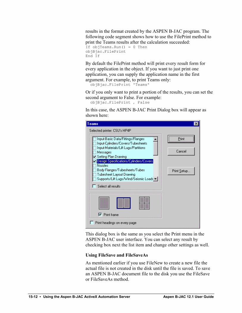
15-12 • Using the Aspen B-JAC ActiveX Automation Server Aspen B-JAC 12.1 User Guide
results in the format created by the ASPEN B-JAC program. The following code segment shows how to use the FilePrint method to print the Teams results after the calculation succeeded: If objTeams.Run() = 0 ThenobjBjac.FilePrintEnd If
By default the FilePrint method will print every result form for every application in the object. If you want to just print one application, you can supply the application name in the first argument. For example, to print Teams only: objBjac.FilePrint "Teams"
Or if you only want to print a portion of the results, you can set the second argument to False. For example: objBjac.FilePrint , False
In this case, the ASPEN B-JAC Print Dialog box will appear as shown here:
This dialog box is the same as you select the Print menu in the ASPEN B-JAC user interface. You can select any result by checking box next the list item and change other settings as well.
Using FileSave and FileSaveAs As mentioned earlier if you use FileNew to create a new file the actual file is not created in the disk until the file is saved. To save an ASPEN B-JAC document file to the disk you use the FileSave or FileSaveAs method.

Aspen B-JAC 12.1 User Guide Using the Aspen B-JAC ActiveX Automation Server • 15-13
Use the FileSaveAs method or to save a copy of an existing document under a different name or an existing document to a different drive or path. For example, supply an existing filename, path to save, and name a new document:
objBjac.SaveAs "C:\Program File\MyBJACFile\Exchanger.BJT"
Use the FileSave method to save the document in the same filename, or in the default name defined by the program. For example: objBjac.Save
It is strongly recommended that you use the FileSaveAs method to save the document in a desire filename if the document was newly created using the FileNew method. Because the default filename defined by the program is UNTITLE.BJT.
The argument of the FileSaveAs method can be omitted. If do so, a standard "Save As" Windows dialog box will appear and you will be able to specify any filename or file path.
The ASPEN B-JAC Automation Server provides following collections to keep track of the objects: • Application collection: BJACApp.ATVApps • Scalar data collection for input: ATVApp.Scalars • Array data collection for input: ATVApp.Arrays • Scalar data collection for results: ATVApp.ResultScalars • Array data collection for results: ATVApp.ResultArrays
You can use For Each �Next to enumerate the objects in the collections, without losing any part of the information for the BJACApp object. This is particularly important if you want to generate your own database to store input and results information rather than using the ASPEN B-JAC document, or create your own graphic user interface to access the ASPEN B-JAC objects.
The following example code prints names and values for all scalar variables in the input: Dim objApp as ATVAppDim objScalar as ATVScalar
…For Each objScalar In objApp.ScalarsDebug.Print objScalar.Name, objScalar.Value
Next
Checking Status for an application or for a data object is important when you want to know whether you have made changes to the application, whether you can run the program, or whether the results are present.
Enumerating Objects
Checking Status

15-14 • Using the Aspen B-JAC ActiveX Automation Server Aspen B-JAC 12.1 User Guide
Using IsSaved The IsSaved property is provided in the BJACApp object and the ATVApp object. You can use this property to check to see if any change in the input of the document has been made and the changes have not been saved. This is particularly useful when changes have been made and you need to save these changes.
The following code gives an example that shows how to use the property: Private Sub SaveFile(ByVal objBjac as BJACApp )If Not objBjac.IsSaved ThenobjBjac.FileSave
End IfEnd Sub
If you just want to check to see if a particular application has been modified or not, you can query the ATVApp.IsSaved property. For example:
Dim objHetran as ATVApp…If Not objHetran.IsSaved ThenobjBjac.FileSave
End If
Notice that once the document is saved the IsSaved property will return a value of True to reflect the change of the status.
Using IsComplete The IsComplete property is used to check the completion status for an application or check for required input data. The ASPEN B-JAC object provides a variety of comprehensive algorithms checking the completion status for applications based on various input conditions. The IsComplete property returns a value of True to indicate the status is complete.
Use the IsComplete property in an ATVApp object to check the completion status for the application. For example: Dim objHetran as ATVApp…If objHetran.IsComplete then
‘ the input is complete,…End if
Use the IsComplete property in a data object to check to see if the input data is complete. For an input data, if the data is not required then the property always returns True. If the data is required and the value is missing then the IsComplete property returns False.
The following example shows how to find an incomplete data in the input scalar objects:

Aspen B-JAC 12.1 User Guide Using the Aspen B-JAC ActiveX Automation Server • 15-15
Function FindIncompleteData(ByVal objApp As ATVApp)As ATVScalar
Dim objScalar As ATVScalar
' Loops through the scalar objectsFor Each objScalar In objApp.Scalars
' Checks to see if the data is completeIf Not objScalar.IsComplete Then
' Found the first incomplete data, return the dataand exit
Set FindIncompleteData = objScalarExit Function
End IfNext
End Function
The ASPEN B-JAC user interface has provided a solution to handle the complexity of different units of measure. Through the ASPEN B-JAC user interface, you can add your own units, or change any existing units in the units table, and then use these new or modified units for input field, calculation or printed results without even closing the application window.
The ASPEN B-JAC Automation Server provides you three different levels to control the units of measure in your program: • The UomSet property in the BACApp object • The UomSet property in the ATVApp object • The Uom property in the data objects
UomSet in BJACApp Object Use the UomSet property in the BJACApp object to view or change the units of measure set for the BJACApp object. For example: Dim objBjac as BJACAppDim nSet as Integer…
‘ Gets the current units setnSet = objBjac.UomSet
‘ Checks to see if it’s SI, if not then change it toSIif nSet <> ATV_UOMSET_SI then objBjac.UomSet =
ATV_UOMSET_SI
Note: The UomSet property is the default units set for application objects. Changing UomSet in the BJACApp object will not have any effect on the applications that are already created.
Controlling the Units of Measure

15-16 • Using the Aspen B-JAC ActiveX Automation Server Aspen B-JAC 12.1 User Guide
UomSet in ATVApp Object Use the UomSet property in an ATVApp object to return or change the units of measure set for the application. For example: Dim objApp as ATVApp. . .
‘ Sets the units set to user defined SET1objApp.UomSet = ATV_UOMSET_SET1
Note: By changing the UomSet in the ATVApp object, the units of physical quantity data objects in the application will be changed to the units defined in the units set table. Consequently the values of these data will be converted appropriately to the new units if the current units set is different. Also, you will notice that the units controls in the ASPEN B-JAC user interface will prompt in accordance with the changes.
Uom in ATVScalar Object and ATVArray Object Use the Uom property in the ATVScalar and ATVArray objects to view or change the units of measure for the data. For example: Dim objHetan as ATVApp…
‘ Changes the units of hot side flowrate to "lb/s"objHetran.Scalars("FlRaHS").Uom = "lb/s"
Notes: • The Uom property only applies to the physical quantity data,
for example, temperature and pressure. • The Uom property is a string. You must assign an existing unit
string to the data. The unit string remains unchanged if an invalid unit string is supplied.
• Changing the unit string will not result in the value being converted.
The data in the ASPEN B-JAC applications can be accessed through the two data objects: ATVScalar and the ATVArray. You can not create a new data object, but you can access all the attributes including changing the value or unit string for all the data objects. To access a data of interest, one possible method is as follows: • Locate the variable of interest. • Find out the attributes for the variable. Especially, you need to
know the variable is a scalar or an array, and input or result. • Get the reference to the data object using the appropriate data
object collection. • View or change the value or unit string if necessary.
Accessing Data

Aspen B-JAC 12.1 User Guide Using the Aspen B-JAC ActiveX Automation Server • 15-17
Detailed information about the data objects is given in the Reference Information section.
In order to access the data of interest in an ASPEN B-JAC design, you need to locate the variables of interest in the system. To do this, you can use the Application Browser together with the Variable List Window in the ASPEN B-JAC User Interface to navigate the data.
In the ASPEN B-JAC user interface, every application, for example, Hetran, is represented in an Application Browser. The Application Browser has a tree structure and contains the visual representation for inputs and results in a series of forms. On each form, for input and results, each data control is connected a data object, and each data has a variable associated with it. The Variable List window will list all the variables behind the form.
To open the Variable List Window, from the View menu, click Variable List.
The Variable List Window displays the attributes including names, variable type, current values, and descriptions for all the variables used on the form.
Notice that the indicates an input variable, and the indicate a result variable.
Another way to locate a variable is to view the variable attributes in the description pane on the Application Browser by clicking a control.
To show the variable attributes on the description pane:
Exploring Variables
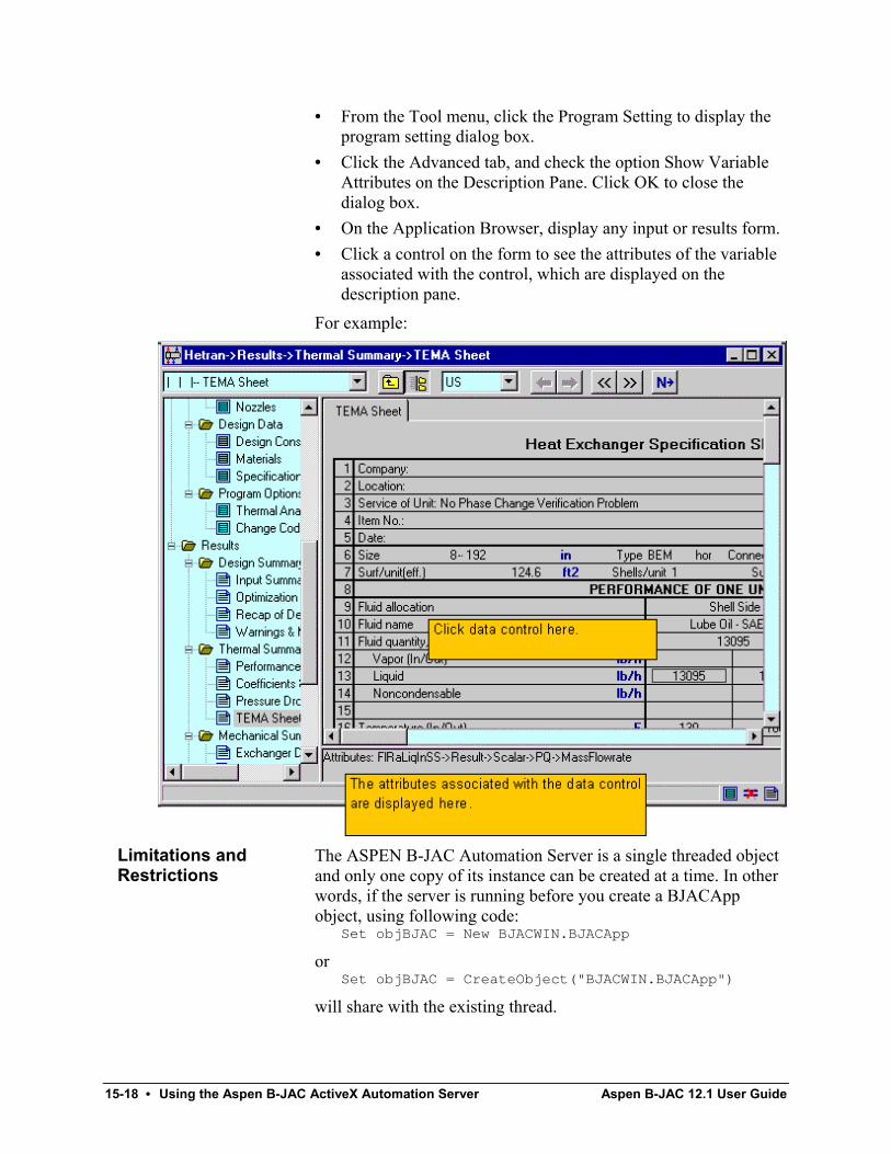
15-18 • Using the Aspen B-JAC ActiveX Automation Server Aspen B-JAC 12.1 User Guide
• From the Tool menu, click the Program Setting to display the program setting dialog box.
• Click the Advanced tab, and check the option Show Variable Attributes on the Description Pane. Click OK to close the dialog box.
• On the Application Browser, display any input or results form. • Click a control on the form to see the attributes of the variable
associated with the control, which are displayed on the description pane.
For example:
The ASPEN B-JAC Automation Server is a single threaded object and only one copy of its instance can be created at a time. In other words, if the server is running before you create a BJACApp object, using following code:
Set objBJAC = New BJACWIN.BJACApp
or Set objBJAC = CreateObject("BJACWIN.BJACApp")
will share with the existing thread.
Limitations and Restrictions

Aspen B-JAC 12.1 User Guide Using the Aspen B-JAC ActiveX Automation Server • 15-19
The BJACApp object can only deal with one document at a time. If you try to create another new document or open another existing document, the consequence is that the program will unload the current document first.
Although multiple ATVApp objects can co-exist in the BJACApp object, you can only create one kind of the application object at a time. For example, the Hetran object, is not allowed having more than one copy. In other words, you can not create two Hetran applications in the same BJACApp object.
Only the BJACApp object can be created in your code. Other objects can only be referenced. The object collections can only be referenced. You can not add any item to the collections. If you try to do so, it may cause unpredictable results.
Reference Information The topics in this section includes: • Lists of the members for each exposed ASPEN B-JAC classes • Member descriptions • Error descriptions
Name Member Type Data Type Description
Aerotran Function Object Returns the ATVApp object for AerotranATVApps Property (Get) Collection Returns the ATVApp objects collection ExecutionControlEnabled Property (Get/Let) Boolean Returns/sets a value that determines
execution control FileClose Sub Closes the current document FileExit Sub Terminates the program FileNew Function Boolean Creates a new document FileOpen Function Boolean Opens an existing document FilePrint Sub Prints the results FileSave Function Boolean Saves the document FileSaveAs Function Boolean Saves the document to a different file GetApp Function Object Returns an ATVApp object GetFileName Function String Returns the current document filename GetFilePath Function String Returns path name GetList Function Long Retrieves static list information GetListCollection Function Long Retrieves static list information GetUomString Function String Returns a valid units string GetVersion Function String Returns the version information
Members of Class BJACApp
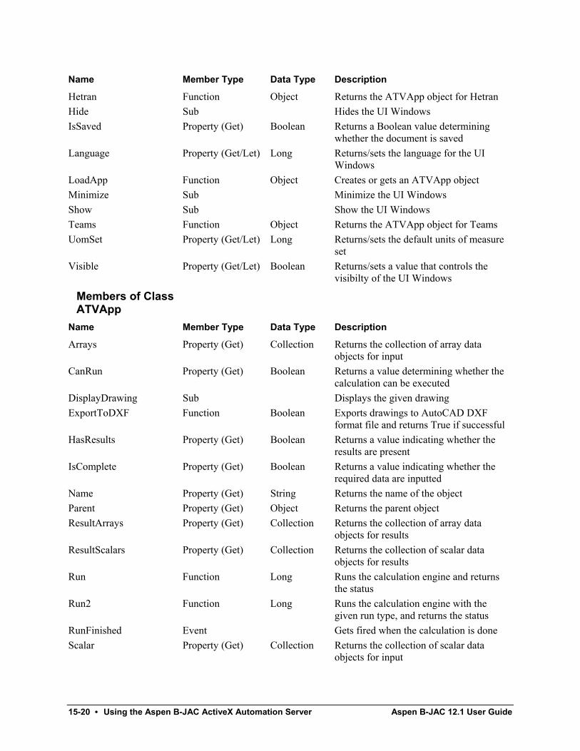
15-20 • Using the Aspen B-JAC ActiveX Automation Server Aspen B-JAC 12.1 User Guide
Name Member Type Data Type Description
Hetran Function Object Returns the ATVApp object for Hetran Hide Sub Hides the UI Windows IsSaved Property (Get) Boolean Returns a Boolean value determining
whether the document is saved Language Property (Get/Let) Long Returns/sets the language for the UI
Windows LoadApp Function Object Creates or gets an ATVApp object Minimize Sub Minimize the UI Windows Show Sub Show the UI Windows Teams Function Object Returns the ATVApp object for Teams UomSet Property (Get/Let) Long Returns/sets the default units of measure
set Visible Property (Get/Let) Boolean Returns/sets a value that controls the
visibilty of the UI Windows
Name Member Type Data Type Description
Arrays Property (Get) Collection Returns the collection of array data objects for input
CanRun Property (Get) Boolean Returns a value determining whether the calculation can be executed
DisplayDrawing Sub Displays the given drawing ExportToDXF Function Boolean Exports drawings to AutoCAD DXF
format file and returns True if successful HasResults Property (Get) Boolean Returns a value indicating whether the
results are present IsComplete Property (Get) Boolean Returns a value indicating whether the
required data are inputted Name Property (Get) String Returns the name of the object Parent Property (Get) Object Returns the parent object ResultArrays Property (Get) Collection Returns the collection of array data
objects for results ResultScalars Property (Get) Collection Returns the collection of scalar data
objects for results Run Function Long Runs the calculation engine and returns
the status Run2 Function Long Runs the calculation engine with the
given run type, and returns the status RunFinished Event Gets fired when the calculation is done Scalar Property (Get) Collection Returns the collection of scalar data
objects for input
Members of Class ATVApp

Aspen B-JAC 12.1 User Guide Using the Aspen B-JAC ActiveX Automation Server • 15-21
Name Member Type Data Type Description
UomSet Property (Get/Let) Collection Returns or sets the units of measure set for the application
Name Member Type Data Type Description
Category Property (Get) Long Returns a value that indicates the data category
IsComplete Property (Get) Boolean Returns a value that indicates whether the required data is inputted
IsEmpty Function Boolean Check to see if the data is empty Name Property (Get) String Returns the name of the data object Parent Function (Get) Object Returns the parent object PQOrListType Property (Get) String Returns the physical quantity name if the
data is a physical quantity, or the name of the list if the data is a static list.
Text Property (Get) String Returns a supplemental information Uom Property (Get/Let) String Returns a string that represents the unit
for a physical quantity data. Value Property (Get/Let) Variant Returns/sets a value for the data
Name Member Type Data Type Description
Category Property (Get) Long Returns a value that indicates the data category
Insert Sub Insets an element in the array IsComplete Property (Get) Boolean Returns a value that indicates whether the
required data are inputted IsElementEmpty Function Boolean Check to see if the given element is
empty IsEmpty Function Boolean Check to see if the whole array is empty Name Property (Get) String Returns the name Parent Property (Get) Object Returns the parent object PQOrListType Property (Get) String Returns the physical quantity name if the
data is a physical quantity, or the name of the list if the data is a static list.
Remove Sub Removes an element from the array Text Property (Get) String Returns a supplemental information Uom Property (Get/Let) String Returns a string that represents the unit
for a physical quantity data. Values Property (Get/Let) Variant Returns/sets a value for the given
element
Members of Class ATVScalar
Members of Class ATVArray

15-22 • Using the Aspen B-JAC ActiveX Automation Server Aspen B-JAC 12.1 User Guide
The descriptions of the Methods, Properties, and Events in the B-JAC classes follow.
Gets a reference to an ATVApp object that represents the Aerotran application.
Applies To BJACApp Object
Syntax object.Aerotran
Data Type Object
Remarks: This method is the same as the statement: Set objAerotran = object.GetApp("Aerotran").
Gets a reference to the collection containing array data objects for input in an ATVApp object.
Applies To ATVApp Object
Syntax object.Arrays
Data Type Collection
Gets a reference to the collection containing the ATVApp objects in the BJACApp object.
Applies To BJACApp Object
Syntax object.ATVApps
Data Type Collection
Remarks: In the ASPEN B-JAC object, an application object named "UTILITIES" is always loaded for the internal service purpose. This internal application object has no visual representation and will stay the BJACApp object as long as a document is loaded.
Returns a Boolean value that determines whether or not the calculation engine can be executed.
Applies To ATVApp Object
Syntax object.CanRun
Data Type Boolean
Remarks If the property ExecutionControlEnabled in the BJACApp object is True, the CanRun method will be controlled by the completion of the input. In this case, if the IsComplete method in the application object returns True, then the CanRun also is True. However, if the BJACApp.ExecutionControlEnabled is False, the CanRum always returns True.
Returns a long integer that determines the category for the data object.
Applies To ATVScalar Object, ATVArray Object
Member Descriptions
Aerotran Method
Arrays Property (Read-only)
ATVApps Property (Read-only)
CanRun Property (Read-only)
Category Property (Read-only)

Aspen B-JAC 12.1 User Guide Using the Aspen B-JAC ActiveX Automation Server • 15-23
Syntax object.Category
Data Type Long
Remarks The ASPEN B-JAC object has defined following seven constants for the data category:
Constant Value VB Data Type
Description
ATV_DATACATEGORY_PQ 0 Single Physical quantities, such as temperature and pressure.
ATV_DATACATEGORY_LIST 1 Long StaticList, such as TEAM Class. A StaticList data has a list of items from which the use can select one and the index of the item selected will be returned as the value of the data.
ATV_DATACATEGORY_NUM 2 Single Numeric number ATV_DATACATEGORY_STR 3 String Character string ATV_DATACATEGORY_BOOL
4 Boolean Boolean data
ATV_DATACATEGORY_VOC 5 String Vocabulary (internal use only) ATV_DATACATEGORY_MSG 6 String Message (internal use only)
Displays the given drawing.
Applies To ATVApp Object
Syntax object.DisplayDrawing (hWndClient, DrawingID)
Parameters hWndClient Long Required. A long value representing the
handle of client window, on which the drawing will be displayed.
DrawingID Long Required. A long value representing the drawing to be displayed. See Drawing ID Definitions below for details.
Drawing ID Definitions ID Description Hetran Teams Aerotran Ensea
10 Outline x x x 11 Setting plan x x 20 Material
specifications x
30 Sectional x 40 Bundle layout x 50 Tubesheet layout x x x x 60 Shell x 61 Shell A x 62 Shell B x
DisplayDrawing Method

15-24 • Using the Aspen B-JAC ActiveX Automation Server Aspen B-JAC 12.1 User Guide
ID Description Hetran Teams Aerotran Ensea
70 Shell cover x 80 Front head x 90 Rear head x 100 Floating head x 110 Bundle x 120 Baffles x 130 Flat covers x 140 Front tubesheet x 150 Rear tubesheet x 160 Expansion joint x 171 Gaskets A x 172 Gaskets B x 173 Gaskets C x 181 Body flanges A x 182 Body flanges B x 183 Body flanges C x 184 Body flanges D x 185 Body flanges E x 186 Body flanges F x 190 Vertical supports x 191 Bottom front
supports x
192 Top front Supports
x
193 Bottom rear Supports
x
194 Top rear supports x 200 Weld details x
Example The following code shows how to display the Setting Plan drawing on a VB PictureBox control. To try this example, paste the code into the Declarations section of a form with a PictureBox control, Picture1, and two command bottoms, Command1 and Command2:
Dim objBjac As ObjectDim objApp As Object
Private Sub Command1_Click()' Displays a FileOpen dialog box and let' user to select a BJAC document file' Note: the BJAC document must contain Teams' in order to test the drawing
objBjac.FileOpen

Aspen B-JAC 12.1 User Guide Using the Aspen B-JAC ActiveX Automation Server • 15-25
' Releases the object firstSet objApp = Nothing
' Gets a Teams referenceIf objApp Is Nothing Then Set objApp = NothingSet objApp = objBjac.GetApp("Teams")
If objApp is Nothing ThenBeepMsgBox "The document doesn't contain Teams." & vbCrLf & _
"Please try a differnet file."Else
' Displays the setting plan' Note: 11 is the drawing ID for setting plan
objApp.DisplayDrawing Picture1.hWnd, 11End If
' Displays the setting plan' Note: 11 is the drawing ID for setting plan
If Not objApp Is Nothing ThenobjApp.DisplayDrawing Picture1.hWnd, 11
End IfEnd Sub
Private Sub Command2_Click()Unload Me
End Sub
Private Sub Form_Load()
' Creates a BJAC objectSet objBjac = CreateObject("BJACWIN.BJACApp")
' Checks the errorIf objBjac Is Nothing Then
BeepMsgBox "Can't create BJAC object"Unload Me
End IfEnd Sub
Private Sub Form_Unload(Cancel As Integer)Set objApp = NothingSet objBjac = Nothing
End Sub
Private Sub Picture1_Paint()' Since the drawing doesn't get repainted automatically,' we need to repaint.
If Not objApp Is Nothing Then objApp.DisplayDrawingPicture1.hWnd, 11End Sub
Returns or sets a Boolean value that determines whether or not the program can take control of the calculation execution. When set to True, the input must be complete in order to execute the calculation engine. When set to False, the calculation engine can be launched at any time.
Applies To BJACApp Object
Syntax object.ExecutionControlEnabled [ = Boolean ]
ExecutionControlEnabled Property

15-26 • Using the Aspen B-JAC ActiveX Automation Server Aspen B-JAC 12.1 User Guide
Data Type Boolean
Exports the drawings to AutoCAD DXF format file and returns True if the function succeeds.
Applies To ATVApp Object
Syntax object.ExportToDXF( [DrawingID][,DXFFileName]) Data Type Boolean
Parameters DrawingID Long Optional. A long value representing
the drawing to be exported. If omitted, all the drawings in the object will be exported. For detailed definitions for DrawingID, see the DisplayDrawing method.
DXFFileName String Optional. A string value representing the filename drawing to be exported. If omitted, the current document file will be used. Note: If DrawingID is omitted, each drawing will be saved to a file with corresponding DrawingID appended to the DXFFileName.
Closes the current open document.
Applies To BJACApp Object
Syntax object.FileClose
Remarks The FileClose method will close all of the application user interface windows associated with the open document and destroy all the objects associated with the document as well. Note: Prior to calling this method, you should release all the objects you have referenced in the code except the BJACApp object.
Example Dim objBjac As ObjectDim obhApp As ObjectDim objDat As Object. . .‘ Gets a reference to the App objectSet objApp = objBjac.ATVApps("Aerotran")
‘ Gets a reference to a dataSet objDat = objApp.Arrays("BJACDBSymbHS"). . .
ExportToDXF Method
FileClose Method

Aspen B-JAC 12.1 User Guide Using the Aspen B-JAC ActiveX Automation Server • 15-27
‘ Release the references prior to calling FileCloseSet objApp = NothingSet objDat = Nothing
‘ Call FileClose to destroy the documentobjBjac.Close. . .
Destroys all the objects in the BJACApp object.
Applies To BJACApp Object
Syntax object.FileExit
Remarks The FileExit method will perform following steps: • Close all of the application user interface windows associated
with the open document if the necessary. • If there is no running BJACWIN.EXE prior to the BJAC object
is created in your code, the FileExit method will also destroy the ASPEN B-JAC user interface main window.
Note 1) Prior to calling this method, you should release all the objects referenced in your code in the opposite sequence of referencing. 2) Instead of calling this method, you could simple use Set objBjac = Nothing in your code.
Creates a document and returns a Boolean value indicating whether or not the process succeeded.
Applies To BJACApp Object
Syntax object.FileNew( [AppName])
Data Type Boolean
Parameters AppName String Optional. A string value representing the
name of an application to be created. If omitted, the File New Dialog box appears and user can select one or more applications to create.
Opens an existing document from the disk and returns a Boolean value indicating whether or not the process succeeded.
Applies To BJACApp Object
Syntax object.FileOpen( [Filename])
Data Type Boolean
FileExit Method
FileNew Method
FileOpen Method

15-28 • Using the Aspen B-JAC ActiveX Automation Server Aspen B-JAC 12.1 User Guide
Parameters Filename String Optional. A string value representing the
name of an existing document file to be opened. If omitted, the standard Windows FileOpen Dialog box will be displayed to allow user to open any existing document.
Prints the results for the document if results are present.
Applies To BJACApp Object
Syntax object.FilePrint( [AppName], [PrintAll])
Parameters AppName String Optional. A string value representing the
name of an application to be printed. If omitted, every application will be printed.
PrintAll Boolean Optional. A Boolean value that determines whether or not to print all of the results. If False, then the Print Selection Dialog box appears and user can select the results to print.
Saves the current document file to a disk without changing the name and returns a Boolean value indicating whether or not the process succeeded.
Applies To BJACApp Object
Syntax object.FileSave
Data Type Boolean
Saves a copy of the document to the disk using a different name or path and returns a Boolean value indicating whether or not the process succeeded.
Applies To BJACApp Object
Syntax object.FileSaveAs( [Filename])
Data Type Boolean
Parameters Filename String Optional. A string value representing the
full path name of the document to be saved. If omitted, the standard Windows FileSaveAs Dialog box appears and user will be able to specify the name through the dialog.
Returns a reference to the specified ATVApp object if succeeded or Nothing if failed.
Applies To BJACApp Object
FilePrint Method
FileSave Method
FileSaveAs Method
GetApp Method
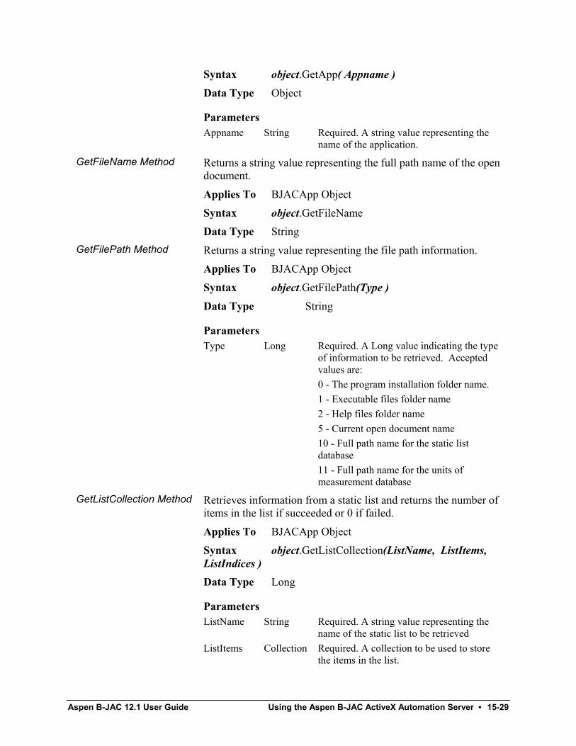
Aspen B-JAC 12.1 User Guide Using the Aspen B-JAC ActiveX Automation Server • 15-29
Syntax object.GetApp( Appname )
Data Type Object
Parameters Appname String Required. A string value representing the
name of the application.
Returns a string value representing the full path name of the open document.
Applies To BJACApp Object
Syntax object.GetFileName
Data Type String
Returns a string value representing the file path information.
Applies To BJACApp Object
Syntax object.GetFilePath(Type )
Data Type String
Parameters Type Long Required. A Long value indicating the type
of information to be retrieved. Accepted values are: 0 - The program installation folder name. 1 - Executable files folder name 2 - Help files folder name 5 - Current open document name 10 - Full path name for the static list database 11 - Full path name for the units of measurement database
Retrieves information from a static list and returns the number of items in the list if succeeded or 0 if failed.
Applies To BJACApp Object
Syntax object.GetListCollection(ListName, ListItems, ListIndices ) Data Type Long
Parameters ListName String Required. A string value representing the
name of the static list to be retrieved ListItems Collection Required. A collection to be used to store
the items in the list.
GetFileName Method
GetFilePath Method
GetListCollection Method

15-30 • Using the Aspen B-JAC ActiveX Automation Server Aspen B-JAC 12.1 User Guide
ListIndices Collection Required. A collection to be used to store the corresponding indices for the list
Example The following code shows how to retrieve the shell type list in the ASPEN B-JAC static list database:
Dim objBjac As ObjectDim ListItems As CollectionDim ListInices As CollectionDim nItems As LongDim I as Long. . .
nItems = objBjac.GetListCollection("ShellType",ListItems,ListIndices)
For I = 1 to nItmesDebug.Print ListIndices(I),"," ListItems(I)
Next I. . .
The code will print following results on the debug window: 0, Program1, E – one pass shell2, F - two pass shell with long. baffle3, G - split flow4, H - double split flow5, J - divided flow (nozzles: 1 in, 2 out)6, K – kettle7, X – crossflow8, V - vapor belt9, J - divided flow (nozzles: 2 in, 1 out)
Returns the number of elements in the array data object.
Applies To ATVArray Object
Syntax object.GetSize
Data Type Long
Returns a string value representing the current version information of the program.
Applies To BJACApp Object
Syntax object.GetVersion
Data Type String
Returns a Boolean value that indicates whether or not the results are present.
Applies To ATVApp Object
Syntax object.HasResults
Data Type Boolean
GetSize Method
GetVersion Method
HasResults Property (Read-only)

Aspen B-JAC 12.1 User Guide Using the Aspen B-JAC ActiveX Automation Server • 15-31
Gets a reference to an ATVApp object that represents the Hetran application.
Applies To BJACApp Object
Syntax object.Hetran
Data Type Object
Remarks The following statements will have the same results: Set objApp = objBjac.HetranSet objApp = objBjac.GetApp("Hetran")Set objApp = objBjac.ATVApps("Hetran")
Hides the ASPEN B-JAC user interface.
Applies To BJACApp Object
Syntax object.Hide
Remarks This is the same as if you use the statement: object.Visible = False
Inserts an element into the array data object.
Applies To ATVArray Object
Syntax object.Insert(Data [,Index] )
Parameters Data Variant Required. A variant value to be assigned Index Long Optional. A Long value indicating where
the new element should be inserted after. If omitted, the new element will be added to the last.
Returns a Boolean value that indicates whether or not the required data are inputted.
Applies To ATVApp Object, ATVArray Object, ATVScalar Object
Syntax object.IsComplete
Data Type Boolean
Returns a Boolean value that indicates whether or not an element in the array data is empty.
Applies To ATVArray Object
Syntax object.IsElementEmpty(Index )
Data Type Boolean
Hetran Method
Hide Method
Insert Method
IsComplete Property (Read-only)
IsElementEmpty Method

15-32 • Using the Aspen B-JAC ActiveX Automation Server Aspen B-JAC 12.1 User Guide
Parameters Index Long Required. A Long value indicating the
element to be checked.
Remarks Use this method to check an individual element in the array. Use the IsEmpty method to check the entire array.
Returns a Boolean value that indicates whether or not the data is empty.
Applies To ATVArray, ATVSalar Object
Syntax object.IsEmpty
Data Type Boolean
Remarks Use this method to check to see if the data is empty or not. For ATVArray objects, the return is True only if all of the elements in the array are empty.
Returns a Boolean value that indicates whether or not the new changes made to the input of the open document have been saved.
Applies To BJACApp, ATVApp Object
Syntax object.IsSaved
Data Type Boolean
Returns or sets a Long value that determines the language used in the program.
Applies To BJACApp Object
Syntax object.Language [ = Setting% ]
Data Type Long
Remarks Currently, the ASPEN B-JAC program has assigned following constants for language: Constant Value Description
ATV_LANGUAGE_ENGLISH English ATV_LANGUAGE_GERMAN German ATV_LANGUAGE_SPANISH Spanish ATV_LANGUAGE_FRENCH French ATV_LANGUAGE_ITALIAN Italian ATV_LANGUAGE_CHINESE Chinese ATV_LANGUAGE_JAPANESE Japanese
Gets or creates an ATVApp object the specified application. It returns the reference to the object if the method succeeded or Nothing if failed.
Applies To BJACApp Object
IsEmpty Method
IsSaved Property (Read-only)
Language Property
LoadApp Method

Aspen B-JAC 12.1 User Guide Using the Aspen B-JAC ActiveX Automation Server • 15-33
Syntax object.LoadApp( Appname )
Data Type Object
Parameters Appname String Required. A string value representing the
name of the application.
Remarks The LoadApp method will create the object if the specified ATVApp object is available in the BJACApp object. If the object already exists, the method will act like the GetApp method.
Minimize the ASPEN B-JAC user interface Windows
Applies To BJACApp Object
Syntax object.Minimize
Returns a string value representing the name of the object.
Applies To ATVApp Object, ATVArray Object, ATVScalar Object
Syntax object.Name
Data Type String
Remarks When used for an ATVApp object, it returns the name for the application, for example, Hetran. When used for an ATVArray object or ATVScalar object it returns the variable name associated with data.
Returns a reference to the parent object.
Applies To ATVApp Object, ATVArray Object, ATVScalar Object
Syntax object.Parent
Data Type Object
Remarks It returns a BJACApp object the ATVApp object, and returns an ATVApp object for the data objects.
Returns a string value that represents the name of the physical quantity or static list assigned to the data.
Applies To ATVScalar Object, ATVArray Object
Syntax object.PQOrListType
Data Type String
Remarks The PQOrListType property is used only for data that are physical quantities or lists. The property returns the name of the physical quantity or the list.
Minimize Method
Name Property (Read-only)
Parent Property (Read-only)
PQOrListType Property (Read-only)

15-34 • Using the Aspen B-JAC ActiveX Automation Server Aspen B-JAC 12.1 User Guide
Example The following example shows how to access the PQOrListType property: Dim objHetran As ATVApp. . .‘ For a PQ dataDebug.Print objHetran.Scalars("FlRaHS").PQOrListType‘ For a List dataDebug.Print objHetran.Scalars("ApplTypeHS").PQOrListType. . .The result of these statements prints followingstring on the Debug Window:
MassFlowrateApplicationTypeHS
Removes an element from an array data object.
Applies To ATVArray Object
Syntax object.Remove([Index] )
Parameters Index Long Optional. A Long value indicating the
element to be removed in the array. If omitted, the last element will be removed.
Gets a reference to the collection containing array data objects for results in an ATVApp object.
Applies To ATVApp Object
Syntax object.ResultArrays
Data Type Collection
Gets a reference to the collection containing scalar data objects for results in an ATVApp object.
Applies To ATVApp Object
Syntax object.ResultScalars
Data Type Collection
Launches the calculation engine to perform the calculation and returns a status. It returns 0 if the calculation succeeded and a non-zero error code to indicate an error if the calculation failed.
Applies To ATVApp Object
Syntax object.Run
Data Type Long
Remarks See the error descriptions for error code.
Remove Method
ResultArrays Property (Read-only)
ResultScalars Property (Read-only)
Run Method

Aspen B-JAC 12.1 User Guide Using the Aspen B-JAC ActiveX Automation Server • 15-35
Launches the calculation engine to perform the calculation and returns a status. It returns 0 if the calculation succeeded and a none-zero error code to indicate an error if the calculation failed.
Applies To ATVApp Object
Syntax object.Run2([RunType] )
Data Type Long
Parameters RunType Long Optional. A Long value indicating the type
of calculation to be performed. If omitted, the method will act as same as the Run method. Note: Currently only the Teams application has different run types as shown below: Calculations + Cost + Drawings Calculations only Calculations + Cost Calculations + Drawings
Gets fired when the calculation finished successfully.
Applies To ATVApp Object
Syntax Private Sub object_RunFinished
Example The following example shows how to implement the RunFinished method to catch the event when the calculation is done.
‘ DeclarationsPrivate objBjac as BJACAppPrivate WithEvents objAerotran as ATVApp ‘ you must use WithEvents. . .Private Sub MyMain( )‘ Create a BJACApp object, and open an Aerotran problem file
. . .‘ Get the Aerotran object, and run Aerotran
Set objAerotran = objBjac.AerotranobjAerotran.Run
End SubPrivate Sub objAerotran_RunFinished()‘ Add your code below. For example, retrieve some results
. . .End Sub
Gets a reference to the collection containing scalar data objects for input in an ATVApp object.
Applies To ATVApp Object
Syntax object.Scalars
Data Type Collection
Run2 Method
RunFinished Event
Scalars Property (Read-only)

15-36 • Using the Aspen B-JAC ActiveX Automation Server Aspen B-JAC 12.1 User Guide
Shows the ASPEN B-JAC user interface.
Applies To BJACApp Object
Syntax object.Show
Remarks This statement is equivalent to object.Visible = False
Returns supplemental information to the Value property of the data object.
Applies To ATVArray Object, ATVScalar Object
Syntax object.Text([Index] ) for ATVArray object
object.Text for ATVScalar object
Parameters Index Long Optional. A Long value representing the
element number in the array. If omitted, the first element is assigned.
Data Type String
Remarks The Text property has no effect on the calculation, and is only used to store extra information to help understanding of the Value property. For example, for a data object representing a material, the Value property of the data object will be the material number assigned by the ASPEN B-JAC, and the Text property will contains the description for the material.
Example The example below prints the value and its text of an ATVScalar object on the Debug Window: Private Sub ShowApplicationType( Byval objHetran AsATVApp )Dim objAppType As ATVScalar
‘ Get a reference to application type in hot sideSet objAppType = objHetran.Scalar("ApplTypeHS")
‘ Display the Value and Text in the Debug WindowDebug.Print objAppType.Value, objAppType.Text
End Sub
On the Debug Window, the results are: 1 Liquid, no phase change
Returns or sets a String that represents the unit for a physical quantity data object.
Applies To ATVArrayApp Object, ATVScalar Object
Show Method
Text Property (Read-only)
Uom Property

Aspen B-JAC 12.1 User Guide Using the Aspen B-JAC ActiveX Automation Server • 15-37
Syntax object.Uom [=NewUnitString] )
Data Type String
Remarks If an invalid unit string is supplied, the unit string remains unchanged. Changing the unit string will not cause the value conversion.
Returns or sets a units of measure used in the object.
Applies To BJACApp Object, ATVApp Object
Syntax object.UomSet [=NewSetting%] )
Data Type Long
Remarks The UomSet property accepts the following constants:
Constant Value Description
ATV_UOMSET_US 1 US units set. Predefined in the program.
ATV_UOMSET_SI 2 SI units set. Predefined in the program
ATV_UOMSET_METRIC 3 METRIC units set. Predefined in the program.
ATV_UOMSET_SET1 4 User units set. Customizable through the UI
ATV_UOMSET_SET2 5 User units set. Customizable through the UI
ATV_UOMSET_SET3 6 User units set. Customizable through the UI
When a new setting is assigned to a BJACApp object, the new setting makes no effect on the ATVApp objects that are created already. However, if a new setting is assigned to an ATVApp object, the entire object, including the contained data objects, or even the user interface window that represents the object, will be changed accordingly.
Returns or sets a value to the data object.
Applies To ATVArray Object, ATVScalar Object
Syntax object.Values([Index],[Uom] ) for ATVArray object
object.Value([Uom]) for ATVScalar object
Parameters Index Long Optional. A Long value representing the
element number in the array. If omitted, the first element is assigned.
UomSet Property
Value Property, Values Property

15-38 • Using the Aspen B-JAC ActiveX Automation Server Aspen B-JAC 12.1 User Guide
Uom String Optional. A String value representing the units of measure to be based or assigned if the data is a physical quantity. If omitted the current units of measure will be used. Note When the Uom parameter is used to returns a value, the data will be converted according to the Uom. However, if the Uom parameter is assigned the data object, the value of the data object will not be converted.
Data Type Variant
Remarks The Value or Values property is a variant type variable. Depending on the Category property, it uses different VB data types to represent the data, and assigns different undefined constants when the data is Empty, as shown in the following table:
Data Category VB Data Type
Undefined Value
Note
ATV_DATACATEGORY_PQ Single 0 Used for physical quantities. It returns 0 if the data is empty. You should use the IsEmpty method to check to see if the data is empty.
ATV_DATACATEGORY_LIST Long -30000 Used for StaticList. The Value property represents the index of an item in the list. The Text property stores the item. You must use a valid index number when you assign a value to the property.
ATV_DATACATEGORY_NUM Single 0 User for numeric data except physical quantities. You should use the IsEmpty method to check the empty status.
ATV_DATACATEGORY_STR String "" ATV_DATACATEGORY_BOOL Boolean False
The optional parameter Index is used only for an ATVArray object. It represents the element number in the array object.
The optional parameter Uom is a string description for the units of measure, for example, kg/s for mass flow rate. You can use the Uom parameter to assign a new units of measure to the data, or returns a value based the specified Uom parameter.
Example Dim objHetran As ATVAppDim objArray As ATVArrayDim objScalar As ATVScalarDim Buf As Single. . .‘ Get the reference to the hot side flow rate

Aspen B-JAC 12.1 User Guide Using the Aspen B-JAC ActiveX Automation Server • 15-39
Set objScalar = objHetran.Scalars("FlRaHS")
‘ Get the current value in kg/h no matter what units the data is‘ actually usingBuf = objScalar.Value("kg/h")
‘ Assign the 10000 lb/h to the dataobjScalar.Value("lb/h") = 10000.0 ‘ Now the data’s units is lb/h
‘ Get the reference to the specific heat for liquid cold sideSet objArray = objHetran.Arrays("SpHtLiqCS")
‘ Gets the value of the element #1 in the current unitsBuf = objArray.Values(1)
‘ Assign a value to the element and change the unitsobjArray.Values(1,"kJ/(kg*K)") = 0.2. . .
Returns or set a Boolean value that determines the ASPEN B-JAC user interface is visible or hidden.
Applies To BJACApp Object
Syntax object.Visible [=NewSetting]
Data Type Boolean Number Descriptions
-1 Input is incomplete 1000 An unknown error has occurred. 1001 Unknown security error occurred. 1002 Couldn't detect security key on your system. 1003 Couldn't detect HASP single-user security key on your
system. 1004 Couldn't detect NetHASP key on your system or no active
NetHASP server was found. 1005 License to run the program has expired. 1006 The program doesn't have enough BRUs to run. 1007 Couldn't read security key. 1008 Couldn't write to security key. 1009 The security key date or time has been changed. 1010 Failed to access NetHASP key. 1011 General security key error. 1012 Failed to access Aspen License Manager(ASPLM) or no
active ASPLM was found. 1013 Number of stations that may run the application at the same
time has been exceeded. 1014 No license was found to run the program. 1101 EXCEPTION_ACCESS_VIOLATION has occurred. 1102 EXCEPTION_BREAKPOINT has occurred.
Visible Property
Error Descriptions

15-40 • Using the Aspen B-JAC ActiveX Automation Server Aspen B-JAC 12.1 User Guide
Number Descriptions
1103 EXCEPTION_DATATYPE_MISALIGNMENT has occurred.
1104 EXCEPTION_SINGLE_STEP has occurred. 1105 EXCEPTION_ARRAY_BOUNDS_EXCEEDED has
occurred. 1106 EXCEPTION_FLT_DENORMAL_OPERAND has occurred. 1107 EXCEPTION_FLT_DIVIDE_BY_ZERO has occurred. 1108 EXCEPTION_FLT_INEXACT_RESULT has occurred. 1109 EXCEPTION_FLT_INVALID_OPERATION has occurred. 1110 EXCEPTION_FLT_OVERFLOW has occurred. 1111 EXCEPTION_FLT_STACK_CHECK has occurred. 1112 EXCEPTION_FLT_UNDERFLOW has occurred. 1113 EXCEPTION_INT_DIVIDE_BY_ZERO has occurred. 1114 EXCEPTION_INT_OVERFLOW has occurred. 1115 EXCEPTION_PRIV_INSTRUCTION has occurred. 1116 EXCEPTION_NONCONTINUABLE_EXCEPTION has
occurred. 1200 The file <$> contains an unrecognized format. 1201 Error occurred while accessing a file. 1300 Failed to load Aspen Properties Plus DLL. 1301 Error occurred while executing Aspen Properties Plus. 1400 Fatal error in Aspen Plus / BJAC interface

Aspen B-JAC 12.1 User Guide Appendix • A-1
A P P E N D I X A
Appendix
Tubing B.W.G. Gauge in mm 28 0.014 0.36 27 0.016 0.41 26 0.018 0.46 25 0.20 0.51 24 0.22 0.56 23 0.25 0.64 22 0.028 0.71 21 0.032 0.81 20 0.035 0.89 19 0.042 1.07 18 0.049 1.24 17 0.058 1.47 16 0.065 1.65 15 0.072 1.83 14 0.083 2.11 13 j0.095 2.41 12 0.109 2.77 11 0.120 3.05 10 0.134 3.40 9 0.148 3.76 8 0.165 4.19 7 0.180 4.57 6 0.203 5.16 5 0.220 5.59
Tube Wall Thickness

A-2 • Appendix Aspen B-JAC 12.1 User Guide
B.W.G. Gauge in mm 4 0.238 6.05 3 0.259 6.58 2 0.284 7.21 1 0.300 7.62
Standard fin outside diameters in: 1.5 2.0 2.5 3.0 3.5
mm: 38 50 63 76 89
Program Default: Tube Outside Diameter + 0.75 in or 19.05 mm
Standard fin thickness integral or extruded: 0.012-0.025 in or 0.3-0.7 mm
welded or wrapped: 0.025-0.165 in or 0.6-4 mm in: 0.031 0.036 0.049 0.059 mm: 0.8 0.9 1.2 1.5
Program Defaults: 0.23 in or 0.58 mm for tube O.D. less than 2 in or 50.8
0.36 in or 0.91 mm for tube O.D. greater than 2 in or 50.8 mm
The following list contains the standard available tube sizes that are available for the indicated enhance surfaces.
Manufacture Type Tube OD, in Wall Thk, in
Wolverine TURBO B MHT 1 3/4" OD .051" WALL 2 3/4" OD .054" WALL 3 3/4" OD .059" WALL 4 3/4" OD .065" WALL 7 1" OD .053" WALL Wolverine TURBO B LPD 5 3/4" OD .051" WALL 6 3/4" OD .057" WALL Wolverine TURBO C MHT 1 1" OD .052" WALL 2 3/4" OD .051" WALL 3 3/4" OD .054" WALL 4 3/4" OD .058" WALL
Tube Low Fin Information
Enhanced Surfaces Standard Sizes

Aspen B-JAC 12.1 User Guide Appendix • A-3
Manufacture Type Tube OD, in Wall Thk, in Wolverine TURBO C LPD 5 3/4" OD .051" WALL Wolverine TURBO BII 1 3/4" OD .049" WALL 2 3/4" OD .051" WALL 3 3/4" OD .058" WALL Wolverine TURBO CII 1 3/4" OD .047" WALL 2 3/4" OD .050" WALL 3 3/4" OD .056" WALL Wolverine KORODENSE MHT Wolverine KORODENSE LPD
1 5/8" OD .020" WALL 2 5/8" OD .025" WALL 3 5/8" OD .032" WALL 4 5/8" OD .035" WALL 5 5/8" OD .042" WALL 6 5/8" OD .049" WALL 7 5/8" OD .065" WALL 8 3/4" OD .020" WALL 9 3/4" OD .025" WALL 10 3/4" OD .032" WALL 11 3/4" OD .035" WALL 12 3/4" OD .042" WALL 13 3/4" OD .049" WALL 14 3/4" OD .065" WALL 15 7/8" OD .020" WALL 16 7/8" OD .025" WALL 17 7/8" OD .032" WALL 18 7/8" OD .035" WALL 19 7/8" OD .042" WALL 20 7/8" OD .049" WALL 21 7/8" OD .065" WALL 22 1" OD .020" WALL 23 1" OD .025" WALL 24 1" OD .032" WALL 25 1" OD .035" WALL 26 1" OD .042" WALL 27 1" OD .049" WALL 28 1" OD .065" WALL

A-4 • Appendix Aspen B-JAC 12.1 User Guide
Manufacture Type Tube OD, in Wall Thk, in 29 1-1/8" OD .025" WALL 30 1-1/8" OD .032" WALL 31 1-1/8" OD .035" WALL 32 1-1/8" OD .042" WALL 33 1-1/8" OD .049" WALL 34 1-1/8" OD .065" WALL 35 1-1/4" OD .025" WALL 36 1-1/4" OD .032" WALL 37 1-1/4" OD .035" WALL 38 1-1/4" OD .042" WALL 39 1-1/4" OD .049" WALL 40 1-1/4" OD .065" WALL
Material Selection Abbrev Material CS Carbon Steel C½Mo Low Alloy Steel C½Mo ½Cr½Mo Low Alloy Steel ½Cr½Mo Cr½Mo Low Alloy Steel Cr½Mo 1¼Cr½Mo Low Alloy Steel 1¼Cr½Mo SS 304 High Alloy Steel Grade 304 SS 304L High Alloy Steel Grade 304L SS 316L High Alloy Steel Grade 316L SS 310S High Alloy Steel Grade 310S SS 347 High Alloy Steel Grade 347 SS 310S High Alloy Steel Grade 310S SS XM-27 High Alloy Steel Grade XM-27 SS 410 High Alloy Steel Grade 410
Abbrev Material NI 200 Nickel Alloy 200 NI 201 Nickel Low Carbon Alloy 201 Monel Nickel Alloy 400 (Monel) Inconel Nickel Alloy 600 (Inconel) NI 800 Nickel Alloy 800 NI 825 Nickel Alloy 825 (Incoloy 825) Hast. B Nickel Alloy B (Hastelloy B)
Generic Materials

Aspen B-JAC 12.1 User Guide Appendix • A-5
Abbrev Material Hast. C Nickel Alloy C (Hastelloy C) Hast. G Nickel Alloy G (Hastelloy G) NI 20 Nickel Alloy 20 Cb (Carpenter 20) Titanium Titanium Cu-Ni 70/30 Copper-Nickel 70/30 Alloy CDA 715 Cu-Ni 90/10 Copper-Nickel 90/10 Alloy CDA 706 Cu-Si Copper-Silicon Alloy CDA 655 NavBrass Naval Brass Alloy 464 AlBronze Aluminum-Bronze Alloy 630 AlBrass Aluminum-Brass Alloy 687 Admiralty Admiralty Alloy 443 Tantalum Tantalum Zirconium Zirconium
Specify one of the following generic materials for the gaskets: • compressed fiber • flat metal jacketed fiber • solid flat metal • solid teflon • graphite • spiral wound • ring joint • self-energized • elastomers
Specify one on the following generic gasket materials: • compressed fiber • flat metal jacketed fiber • solid flat metal • solid teflon • graphite • spiral wound • ring joint • self-energized elastomers
The following table is provided as a quick reference for acceptable materials of construction. The corrosion ratings are at a single temperature (usually 20 C) and a single concentration. A final
Gaskets - hot side
Gaskets - cold side
Corrosion Table
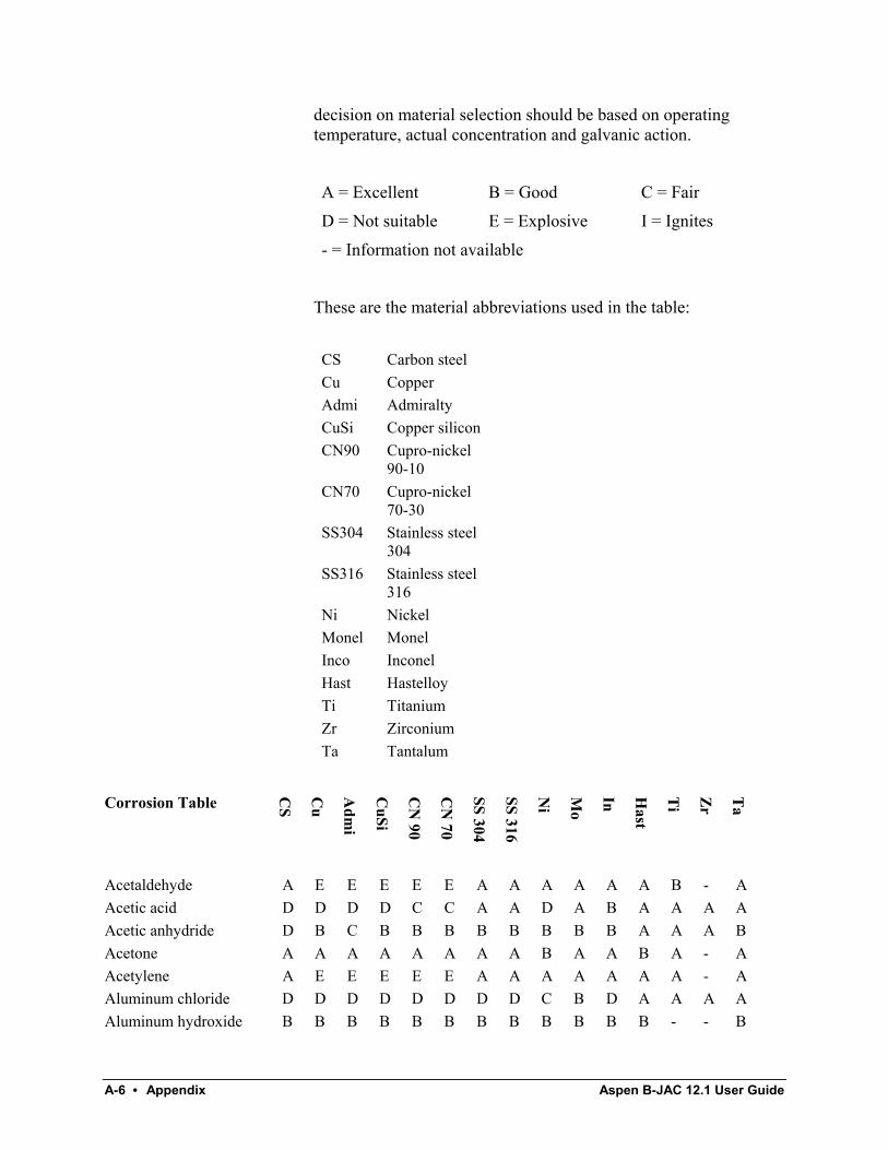
A-6 • Appendix Aspen B-JAC 12.1 User Guide
decision on material selection should be based on operating temperature, actual concentration and galvanic action.
A = Excellent B = Good C = Fair
D = Not suitable E = Explosive I = Ignites
- = Information not available
These are the material abbreviations used in the table:
CS Carbon steel Cu Copper Admi Admiralty CuSi Copper silicon CN90 Cupro-nickel
90-10 CN70 Cupro-nickel
70-30 SS304 Stainless steel
304 SS316 Stainless steel
316 Ni Nickel Monel Monel Inco Inconel Hast Hastelloy Ti Titanium Zr Zirconium Ta Tantalum
Corrosion Table
CS
Cu
Adm
i
CuSi
CN
90
CN
70
SS 304
SS 316
Ni
Mo
In
Hast
Ti
Zr
Ta
Acetaldehyde A E E E E E A A A A A A B - A Acetic acid D D D D C C A A D A B A A A A Acetic anhydride D B C B B B B B B B B A A A B Acetone A A A A A A A A B A A B A - A Acetylene A E E E E E A A A A A A A - A Aluminum chloride D D D D D D D D C B D A A A A Aluminum hydroxide B B B B B B B B B B B B - - B

Aspen B-JAC 12.1 User Guide Appendix • A-7
Corrosion Table
CS
Cu
Adm
i
CuSi
CN
90
CN
70
SS 304
SS 316
Ni
Mo
In
Hast
Ti
Zr
Ta
Ammonia (anhydrous) A A A A A A A A B A B B A - A Ammonium chloride D D D D D D B B B B B B A A A Ammonium sulfate C C C C C C C C B A B B A A A Ammonium sulfite D B B B B B C C D D D - A - A Amyl acetate B A A B A A A A A A A B A - A Aniline A D D D D D A A B B B B A - A Aroclor B A A A A A B B A A A A A - A Barium chloride B B C B B B B B B B B B A A A Benzaldehyde B B B B B B B B B B B A A - A Benzene A A A A A A B B B B B B A - A Benzoic acid D B B B B B B B B B B B A - A Boric acid D B B B B B A A B B B A A - A Butadiene A A A A A A A A A A A A A - A Butane A A A A A A A A A A A A A - A Butanol A A A A A A A A A A A A A - A Butyl acetate A B B B B B B B A B A B A - A Butyl chloride A A A A A A A A A A A A A - A Calcium chloride B B C B B B C B A A A B A A A Calcium hydroxide B B B B B B B B B B B B A - A Carbon dioxide(wet) C C C C C C A A A A A A A - A Carbon tetrachloride B B B B B B B B A A A B A A A Carbonic acid C C C C C C B B B C A A A - A Chlorine gas (dry) B B B B B B B B B B A B I A A Chloroform (dry) B B B B B B B B A A B B A A A Chromic acid D D D D D D C B D D B B B A A Citric acid D C C C C C C B B B A C A A A Creosote B B B B B B B B B B B B A - A Dibutylphthalate A A A A A A B B B B B B A - A Dichlorobenzene B B B B B B B B B B B B B - A Dichlorofluorometh A A A A A A A B B B B A A - A Diethanolamine A B B B B B A A A A A A A - A Diethyl etheride B B B B B B B B B B B B A - A Diethylene glycol A B B B B B A A B B B B A - A Diphenyl B B B B B B B B B B B B A - A Diphenyl oxide B B B B B B B B B B B B A - A Ethane A A A A A A A A A A A A A - A Ethanolamine B B B B B B A B B B B B B - A

A-8 • Appendix Aspen B-JAC 12.1 User Guide
Corrosion Table
CS
Cu
Adm
i
CuSi
CN
90
CN
70
SS 304
SS 316
Ni
Mo
In
Hast
Ti
Zr
Ta
Ether B B B B B B B B B B B B A - A Ethyl acetate (dry) B B B B B B B B B B B B A - A Ethyl alcohol B B B B B B B B B B B A A A A Ethyl ether B B B B B B B B B B B B A - A Ethylene A A A A A A A A A A A A A - A Ethylene glycol B B B B B B B B B B B B A - A Fatty acids D D D D D D D A B C B A B - A Ferric chloride D D D D D D D D D D D B A D A Ferric sulfate D D D D D D B B D D D A A - A Ferrous sulfate D B B B B B B B D D D B A - A Formaldehyde D B B B B B B B B B B B B - A Furfural B B B B B B B B B B B B A - A Glycerine A A A A A A A A A A A A A - A Hexane A A A A A A A A A A A A A - A Hydrochloric acid D D D D D D D D D D D B D D A Hydrofluoric acid D C D D D C D D D C D A D D D Iodine D D D D D D D D D D D B D - A Isopropanol A B B B B B B B B B B B A - A Lactic acid D B C B B B B A B C A A A A A Linseed oil A B B B B B A A B B B B A - A Lithium chloride B B B B B B B A A A A A - - A Lithium hydroxide B B B B B B B B B B B B - - A Magnesium chloride B B C B B B B B A B A A A A A Magnesium hydroxide B B B B B B B B B B B B A - B Magnesium sulfate B B B B B B A A B B B A A A A Methane A A A A A A A A A A A A A A A Methallyamine C B B B B B B B B C B B B - A Methyl alcohol B B B B B B B B B A B A A A A Methyl chloride (dry) A A A A A A A A B B B B A - A Methylene chloride B B B B B B B B B B B B B - A Monochlorobenzene B B B B B B B B A A A B B - A M.dichl.difl.mehane A A A A A A A A A A A A A - A Monoethanolamine B B B B B B B B B B B - - - A Naptha A B B B B B B B B B B B B - A Napthalene A B B B B B A A A A A B B - A Nickel chloride D B B B B B B B D B D A A A A Nickel sulfate D B B B B B B B B B B B B A A
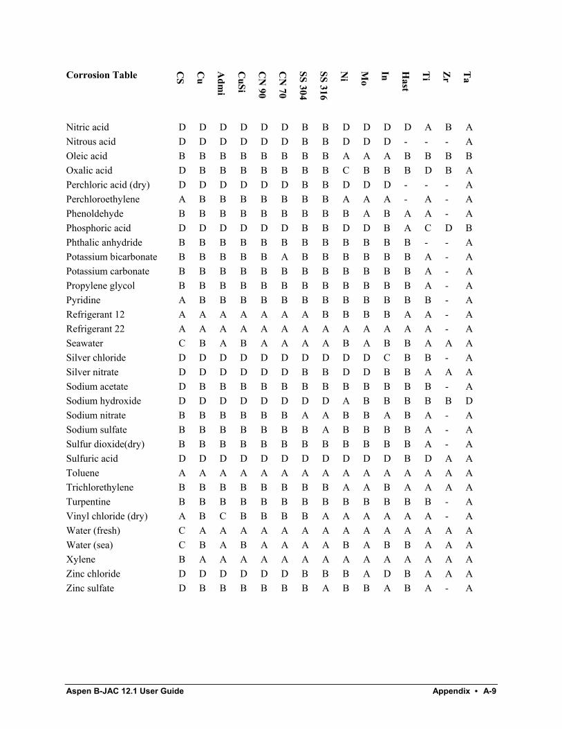
Aspen B-JAC 12.1 User Guide Appendix • A-9
Corrosion Table
CS
Cu
Adm
i
CuSi
CN
90
CN
70
SS 304
SS 316
Ni
Mo
In
Hast
Ti
Zr
Ta
Nitric acid D D D D D D B B D D D D A B A Nitrous acid D D D D D D B B D D D - - - A Oleic acid B B B B B B B B A A A B B B B Oxalic acid D B B B B B B B C B B B D B A Perchloric acid (dry) D D D D D D B B D D D - - - A Perchloroethylene A B B B B B B B A A A - A - A Phenoldehyde B B B B B B B B B A B A A - A Phosphoric acid D D D D D D B B D D B A C D B Phthalic anhydride B B B B B B B B B B B B - - A Potassium bicarbonate B B B B B A B B B B B B A - A Potassium carbonate B B B B B B B B B B B B A - A Propylene glycol B B B B B B B B B B B B A - A Pyridine A B B B B B B B B B B B B - A Refrigerant 12 A A A A A A A B B B B A A - A Refrigerant 22 A A A A A A A A A A A A A - A Seawater C B A B A A A A B A B B A A A Silver chloride D D D D D D D D D D C B B - A Silver nitrate D D D D D D B B D D B B A A A Sodium acetate D B B B B B B B B B B B B - A Sodium hydroxide D D D D D D D D A B B B B B D Sodium nitrate B B B B B B A A B B A B A - A Sodium sulfate B B B B B B B A B B B B A - A Sulfur dioxide(dry) B B B B B B B B B B B B A - A Sulfuric acid D D D D D D D D D D D B D A A Toluene A A A A A A A A A A A A A A A Trichlorethylene B B B B B B B B A A B A A A A Turpentine B B B B B B B B B B B B B - A Vinyl chloride (dry) A B C B B B B A A A A A A - A Water (fresh) C A A A A A A A A A A A A A A Water (sea) C B A B A A A A B A B B A A A Xylene B A A A A A A A A A A A A A A Zinc chloride D D D D D D B B B A D B A A A Zinc sulfate D B B B B B B A B B A B A - A

A-10 • Appendix Aspen B-JAC 12.1 User Guide
Baffle Cuts Single Segmental In all Aspen B-JAC programs, the single segmental baffle cut is always defined as the segment opening height expressed as a percentage of the shell inside diameter.
Typical baffle cut: 15% to 45%
Double Segmental In all Aspen B-JAC programs, the double segmental cut is always defined as the segment height of the innermost baffle window expressed as a percentage of the shell inside diameter. In the output, the baffle cut will be printed with the percent of the inner window / percent of one of the outer windows. The area cut away is approximately equal for each baffle.
Typical baffle cut: 20% to 42%
Triple Segmental In all Aspen B-JAC programs, the triple segmental cut is always defined as the segment height of the innermost baffle window expressed as a percentage of the shell tube inside diameter. In the output, the baffle cut will be printed with the percent of the innermost window / percent of one intermediate window / percent of one outermost window. The area cut away is approximately equal for each baffle.
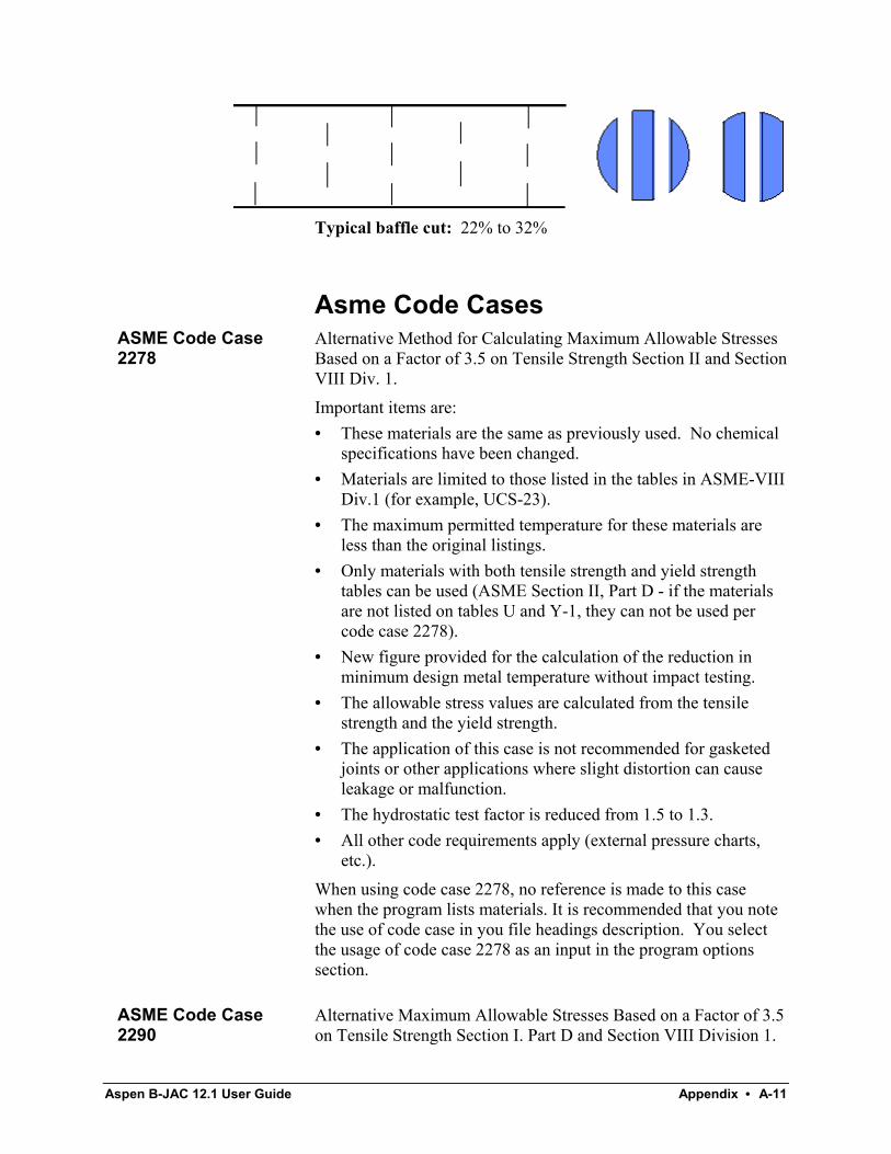
Aspen B-JAC 12.1 User Guide Appendix • A-11
Typical baffle cut: 22% to 32%
Asme Code Cases Alternative Method for Calculating Maximum Allowable Stresses Based on a Factor of 3.5 on Tensile Strength Section II and Section VIII Div. 1.
Important items are: • These materials are the same as previously used. No chemical
specifications have been changed. • Materials are limited to those listed in the tables in ASME-VIII
Div.1 (for example, UCS-23). • The maximum permitted temperature for these materials are
less than the original listings. • Only materials with both tensile strength and yield strength
tables can be used (ASME Section II, Part D - if the materials are not listed on tables U and Y-1, they can not be used per code case 2278).
• New figure provided for the calculation of the reduction in minimum design metal temperature without impact testing.
• The allowable stress values are calculated from the tensile strength and the yield strength.
• The application of this case is not recommended for gasketed joints or other applications where slight distortion can cause leakage or malfunction.
• The hydrostatic test factor is reduced from 1.5 to 1.3. • All other code requirements apply (external pressure charts,
etc.).
When using code case 2278, no reference is made to this case when the program lists materials. It is recommended that you note the use of code case in you file headings description. You select the usage of code case 2278 as an input in the program options section.
Alternative Maximum Allowable Stresses Based on a Factor of 3.5 on Tensile Strength Section I. Part D and Section VIII Division 1.
ASME Code Case 2278
ASME Code Case 2290

A-12 • Appendix Aspen B-JAC 12.1 User Guide
Important items are: • These materials are the same as previously used. No chemical
specifications have been changed. • The alternative maximum allowable stresses are listed in Table
1 of code case 2290 (same format as Section II, Part D materials).
• New figure provided for the calculation of the reduction in minimum design metal temperature without impact testing.
• The application of this case is not recommended for gasketed joints or other applications where slight distortion can cause leakage or malfunction.
• The hydrostatic test factor is reduced from 1.5 to 1.3. • All other code requirements apply (external pressure charts,
etc.).
When using code case 2290, the program will access a new database in which all materials end with the characters '2290'. Therefore, the user and inspector will know what materials fall within this code case. This new database will be listed in the user's interface as 'ASME-2290'. All materials in the new database start from the B-JAC number 5000 (5000-5999). The new database filenames for the engine are AS2290P.PDA and NAS2290I.PDA. The user selects the usage of code case 2290 by selecting any available material in the 5000 series.
Pipe Properties ANSI Pipe Dimensions Dimensions: in
Nom OD 0.75 1.0 1.25 1.5 2.0 2.5 3.0 3.5 4.0 5.0 Actual OD 1.050 1.315 1.660 1.900 2.375 2.875 3.500 4.000 4.500 5.563 Sch 5S 0.065 0.065 0.065 0.065 0.065 0.083 0.083 0.083 0.083 0.109 Sch 10S 0.083 0.109 0.109 0.109 0.109 0.120 0.120 0.120 0.120 0.134 Sch 10 --- --- --- --- --- --- --- --- --- --- Sch 20 --- --- --- --- --- --- --- --- --- --- Sch 30 --- --- --- --- --- --- --- --- --- --- Std 0.113 0.133 0.140 0.145 0.154 0.203 0.216 0.226 0.237 0.258 Sch 40 0.11 0.133 0.140 0.145 0.154 0.203 0.216 0.226 0.237 0.258 Sch 60 --- --- --- --- --- --- --- --- --- --- Ext Str 0.154 0.179 0.191 0.200 0.218 0.276 0.300 0.318 0.337 0.375 Sch 80 0.154 0.179 0.191 0.200 0.218 0.276 0.300 0.318 0.337 0.375 Sch 100 --- --- --- --- --- --- --- --- --- --- Sch 120 --- --- --- --- --- --- --- --- 0.438 0.500 Sch 140 --- --- --- --- --- --- --- --- --- --- Sch 160 0.219 0.250 0.250 0.281 0.344 0.375 0.438 --- 0.531 0.625 XX Str 0.308 0.358 0.382 0.400 0.436 0.552 0.600 --- 0.750 0.864
ANSI Pipe Dimensions

Aspen B-JAC 12.1 User Guide Appendix • A-13
ANSI Pipe Dimensions Dimensions: in Nom OD 6 8 10 12 14 16 18 20 22 24 Actual OD 6.625 8.625 10.75 12.75 14.0 16.0 18.0 20.0 22.0 24.0 Sch 5S 0.109 0.109 0.134 0.156 0.156 0.165 0.165 0.188 0.188 0.218 Sch 10S 0.134 0.148 0.165 0.180 0.188 0.188 0.188 0.218 0.218 0.250 Sch 10 --- --- --- --- 0.250 0.250 0.250 0.250 0.250 0.250 Sch 20 --- 0.250 0.250 0.250 0.312 0.312 0.312 0.375 0.375 0.375 Sch 30 --- 0.277 0.307 0.330 0.375 0.375 0.438 0.500 0.500 0.562 Std 0.280 0.322 0.365 0.375 0.375 0.375 0.375 0.375 0.375 0.375 Sch 40 0.280 0.322 0.365 0.406 0.438 0.500 0.562 0.594 --- 0.688 Sch 60 --- 0.406 0.500 0.562 0.594 0.656 0.750 0.812 0.875 0.969 Ext Str 0.432 0.500 0.500 0.500 0.500 0.500 0.500 0.500 0.500 0.500 Sch 80 0.432 0.500 0.594 0.688 0.750 0.844 0.938 1.031 1.125 1.218 Sch 100 --- 0.594 0.719 0.844 0.938 1.031 1.156 1.281 1.375 1.531 Sch 120 0.562 0.719 0.844 1.000 1.094 1.219 1.375 1.500 1.625 1.812 Sch 140 --- 0.812 1.000 1.125 1.250 1.438 1.562 1.750 1.875 2.062 Sch 160 0.719 0.906 1.125 1.312 1.406 1.594 1.781 1.969 2.125 2.344 XX Str 0.864 0.875 1.000 1.000 --- --- --- --- --- ---
ANSI Pipe Dimensions Dimensions: mm Nom OD 19 25 32 38 51 64 76 89 102 127 Actual OD 26.6 33.4 42.2 48.3 60.3 73.0 88.9 101.6 114.3 141.3 Sch 5S 1.6 1.6 1.6 1.6 1.6 2.1 2.1 2.1 2.1 2.7 Sch 10S 2.1 2.7 2.7 2.7 2.7 3.0 3.0 3.0 3.0 3.4 Sch 10 --- --- --- --- --- --- --- --- --- --- Sch 20 --- --- --- --- --- --- --- --- --- --- Sch 30 --- --- --- --- --- --- --- --- --- --- St --- 3.4 3.6 3.7 3.9 5.2 5.5 5.7 6.0 6.6 Sch 40 2.8 3.4 3.6 3.7 3.9 5.2 5.5 5.7 6.0 6.6 Sch 60 --- --- --- --- --- --- --- --- --- --- Ext Str 3.9 4.5 4.9 5.1 5.5 7.0 7.6 8.1 8.6 9.5 Sch 80 3.9 4.5 4.9 5.1 5.5 7.0 7.6 8.1 8.6 9.5 Sch 100 --- --- --- --- --- --- --- --- --- --- Sch 120 --- --- --- --- --- --- --- --- 11.1 12.7 Sch 140 --- --- --- --- --- --- --- --- --- --- Sch 160 5.5 6.4 6.4 7.1 8.7 9.5 11.1 --- 13.5 15.9 XX Str 7.8 9.1 9.7 10.2 11.1 14.0 15.2 16.2 17.1 19.1
ANSI Pipe Dimensions Dimensions: mm Nom OD 152 203 254 305 356 406 457 508 559 610 Actual OD 168.3 219.1 273.1 323.9 355.6 406.4 457.2 508.0 558.8 609.6 Sch 5S 2.7 2.7 3.4 4.0 4.0 4.0 4.0 4.8 4.8 5.5 Sch 10S 3.4 3.7 4.1 4.5 4.8 4.8 4.8 5.5 5.5 6.3 Sch 10 --- --- --- --- 6.3 6.3 6.3 6.3 6.3 6.3 Sch 20 --- --- --- --- 7.9 7.9 7.9 9.5 9.5 9.5 Sch 30 --- 7.0 7.8 8.4 9.5 9.5 11.1 12.7 12.7 14.3 Std 7.1 8.2 9.3 9.5 9.5 9.5 9.5 9.5 9.5 9.5 Sch 40 7.1 8.2 9.3 10.3 11.1 12.7 14.3 15.1 --- 17.5 Sch 60 --- 10.3 12.7 14.3 15.1 16.7 19.1 20.6 22.2 24.6 Ext Str 11.0 12.7 12.7 12.7 12.7 12.7 12.7 12.7 12.7 12.7 Sch 80 11.0 12.7 15.1 17.5 19.1 21.4 23.8 26.2 28.6 30.9 Sch 100 --- 15.1 18.3 21.4 23.8 26.2 29.4 32.5 34.9 38.9 Sch 120 13.5 18.3 21.4 25.4 27.8 31.0 34.9 38.1 --- 46.0 Sch 140 --- 20.6 25.4 28.6 31.8 36.5 39.7 44.5 --- 52.4 Sch 160 18.3 23.0 28.6 33.3 35.7 40.5 45.2 50.0 --- 59.5 XX Str 21.9 22.2 25.4 25.4 --- --- --- --- --- ---

A-14 • Appendix Aspen B-JAC 12.1 User Guide
DIN / ISO 4200 Pipe Dimensions Dimensions: mm Nom OD 20 25 32 40 50 65 80 100 125 150 Actual OD 26.9 33.7 42.4 48.3 60.3 76.1 88.9 114.3 139.7 168.3 Row A 1.6 1.6 1.6 1.6 1.6 1.6 2.0 2.0 2.0 2.0 Row B --- 2.0 2.0 2.0 2.0 2.3 2.3 2.3 2.3 2.3 Row C --- --- --- --- 2.3 2.6 2.9 2.9 3.2 3.2 Row D 1.8 2.0 2.3 2.3 2.3 2.6 2.9 3.2 3.6 4.0 Row E 2.0 2.3 2.6 2.9 2.9 2.9 3.2 3.6 4.0 4.5 Row F 3.2 3.2 3.6 3.6 4.0 5.0 5.6 6.3 6.3 7.1 Row G 4.0 4.5 5.0 5.0 5.6 7.1 8.0 8.8 10 11
DIN / ISO 4200 Pipe Dimensions Dimensions: mm Nom OD 200 250 300 350 400 450 500 600 700 800 Actual OD 219.1 273 323.9 355.6 406.4 457 508 610 711 813 Row A 2.0 2.0 2.6 2.6 2.6 3.2 3.2 3.2 4.0 4.0 Row B 2.6 3.6 4.0 4.0 4.0 4.0 5.0 5.6 6.3 7.1 Row C 3.6 4.0 4.5 5.0 5.0 5.0 5.6 6.3 7.1 8.0 Row D 4.5 5.0 5.6 5.6 6.3 6.3 6.3 6.3 7.1 8.0 Row E 6.3 6.3 7.1 8.0 8.8 10 11 12.5 14.2 16 Row F 8.0 10 10 11 12.5 14.2 16 17.5 20 22.2 Row G 12.5 14.2 16 17.5 20 22.2 25 30 32 36
ANSI 50 300 400 600 900 1500 2500 ISO 10 16 20 25 40 50 100 DIN 10 16 25 40 63 100 160 250 320 400
Technical References Aspen B-JAC updates its programs with the best of the most recent correlations for heat transfer and pressure drop available from research and published literature sources. The references have been categorized into their applicable areas as follows:
General Shell Side Heat Transfer & Pressure Drop • No Phase Change • Vaporization • Condensation
Tube Side Heat Transfer & Pressure Drop • No Phase Change • Vaporization
DIN / ISO 4200 Pipe Dimensions
Standard Nozzle Flange Ratings
Introduction

Aspen B-JAC 12.1 User Guide Appendix • A-15
• Condensation
Although AspenTech does not publish the exact formulas used in the program, we will gladly direct you to the correct source in the published literature pertaining to your question.
AspenTech continually examines new correlations as they become available and incorporates them into the Aspen B-JAC program only after extensive evaluation. This evaluation includes comparisons of results between new and old correlations, field data from a multitude of units currently in service, and many years of design experience.
Please do not request copies of references from AspenTech. Requests for copies of articles should be made to :
Engineering Societies Library 345 East 47th Street New York, NY 10017 U. S. A.
Perry's Chemical Engineers' Handbook, Sixth Edition, McGraw-Hill, 1984
General Discussion on Heat Transfer, Institution of Mechanical Engineers London, 1951
Practical Aspects of Heat Transfer, AIChE Technical Manual, 1976
Gas Engineers Handbook, C. George Segeler, Industrial Press, 1974
Heat Transfer and Fluid Flow Data Books, General Electric, 1984
Engineering Data Book, Gas Processors Suppliers Association, 1979
Standard Handbook of Engineering Calculations, Second Edition, Tyler G. Hicks, McGraw-Hill, 1985
Heat Exchanger Design Handbooks, Volumes 1-5, Hemisphere Publishing Corporation, 1984
International Heat Transfer Conference Proceedings, Hemisphere Publishing Corporation, Heat Transfer 1978, Toronto Heat Transfer 1982, Munich Heat Transfer 1986, San Francisco Heat Transfer 1990, Jerusalem
AIChE Symposium Heat Transfer Series Seattle 82 Volume 64, 1968 Philadelphia 92 Volume 65, 1969
General

A-16 • Appendix Aspen B-JAC 12.1 User Guide
Minneapolis 102 Volume 66, 1970 Tulsa 118 Volume 68, 1972 Fundamentals 131 Volume 69, 1973 Research & Design 138 Volume 70, 1974 St. Louis 164 Volume 73, 1977 Research & Application 174 Volume 74, 1978 Seattle 225 Volume 79, 1983 Niagara Falls 236 Volume 80, 1984 Denver 245 Volume 81, 1985
Process Heat Transfer, Donald Q. Kern, McGraw-Hill, 1950
Compact Heat Exchangers, Third Edition, Kays & London, McGraw-Hill, 1984
Process Design for Reliable Operations, Norman P. Lieberman, Gulf Publishing Company, 1983
Heat Exchangers: Design and Theory Sourcebook, Afgan & Schlunder, McGraw Hill, 1974
Heat Exchangers Thermal-Hydraulic Fundamentals and Design, Kakac, Bergles & Mayinger, McGraw-Hill, 1981
Convective Boiling and Condensation, John G. Collier, McGraw-Hill, 1972
Industrial Heat Exchangers, A Basic Guide, G. Walker, McGraw-Hill, 1982
Heat Transfer, J.P. Holman, McGraw-Hill, 1981
Heat Transfer in Counterflow, Parallel Flow and Cross Flow, Helmuth Hausen, McGraw-Hill, 1983
Extended Surface Heat Transfer, D.O. Kern & A.D. Kraus, McGraw-Hill, 1972
Heat Exchangers, Theory and Practice, Taborek, Hewitt & Afgan, McGraw-Hill, 1983
Two-Phase Flow and Heat Transfer in the Power and Process Industries, Bergles, Collier, Delhaye, Hewitt & Mayinger, McGraw-Hill, 1981
Standards of Tubular Exchangers Manufacturers Association, Seventh Edition, TEMA, 1988
Wolverine Trufin Engineering Data Book, Wolverine Tube Division, 1967
Heat Transfer Pocket Handbook, Nicholas P. Cheremisinoff, Gulf Publishing Company, 1984
Fluid Flow Pocket Handbook, Nicholas P. Cheremisinoff, Gulf Publishing Company, 1984

Aspen B-JAC 12.1 User Guide Appendix • A-17
Handbook of Chemical Engineering Calculations, Chopey & Hicks, McGraw-Hill, 1984
Heat Exchangers for Two-Phase Applications, ASME, HTD-Vol. 27, 1983
Reprints of AIChE Papers, 17th National Heat Transfer Conference, Salt Lake City, 1977
Standards for Power Plant Heat Exchangers, Heat Exchange Institute Inc., 1980
A Reappraisal of Shellside Flow in Heat Exchangers, ASME HTD-36, 1984
Shellside Waterflow Pressure Drop and Distribution in Industrial Size Test Heat Exchanger, Halle & Wambsganss, Argonne National Laboratory, 1983
Basic Aspects of Two Phase Flow and Heat Transfer, ASME, HTD-Vol. 34, 1984
ASME Heat Transfer Publications, 1979, 18th National Heat Transfer Conference, Condensation Heat Transfer, & Advances in Enhanced Heat Transfer
Shell and Tube Heat Exchangers, Second Symposium, American Society for Metals, Houston, Texas, September, 1981
Two-Phase Heat Exchanger Symposium 23rd National Heat Transfer Conference, Denver, Colorado, HTD-Vol.44 August, 1985
Advances in Enhanced Heat Transfer 23rd National Heat Transfer Conference, Denver, Colorado, HTD-Vol.43 August, 1985
Heat Tranfer Equipment Design, R.K. Shah, Subbarao, and R.A. Mashelkar, Hemisphere Publishing Corporation, 1988
Heat Transfer Design Methods, Edited by John J. McKetta, Marcel Dekker Inc., 1992
Boilers Evaporators & Condesers, Sadik Kakac, John Wiley & Sons Inc., 1991
Enhanced Boiling Heat Transfer, John R. Thome, Hemisphere Publishing Corporation, 1990
Handbook of Heat Transfer Applications Second Edition Editors W.M. Rohsenow, J.P. Hartnett and Ejup N. Ganic, McGraw-Hill Book Co., 1985
Piping Handbook, Sixth Edition, Mobinder L. Nayyar, McGraw-Hill Inc., 1992
A-18 • Appendix Aspen B-JAC 12.1 User Guide
Practical Aspects of Heat Transfer, Proceedings of 1976 Fall Lecture Series of New Jersey-- North Jersey Sections of AICHE, 1976.
Air Cooled Heat Exchangers For General Refinery Services, API Standard 661 Second Edition, January 1978.
ESCOA Fintube Manual, Chris W. Weierman, ESCOA Fintube Corporation
Moore Fan Company Manual, Moore Fan Company, 1982.
Heat Transfer: Research and Application, ed. John Chen, AIChE Symposium Series, No. 174, Vol. 74, 1978
Heat Transfer�Seattle 1983, Nayeem M. Farukhi, AIChE Symposium Series, No. 225, Vol. 79, 1983.
Principles of Heat Transfer, Frank Kreith, International Textbook Company, 1958.
Fundamentals of Heat Transfer, S. S. Kutateladze, Academic Press, 1963.
NGPSA Engineering Data Book, Natural Gas Processors Suppliers Association, 1979.
"Design of Air-Cooled Exchangers," Robert Brown, Chemical Engineering, March 27, 1978.
"Process Design Criteria," V. Ganapathy, Chemical Engineering, March 27, 1978.
Shell Side Characteristics of Shell and Tube Heat Exchangers, Townsend Tinker, ASME Paper No. 56-A-123.
Exchanger Design Based on the Delaware Research Program, Kenneth J. Bell, PETRO/CHEM, October, 1960
Heat Exchanger Vibration Analysis, A. Devore, A. Brothman, and A. Horowitz, Practical Aspects of Heat Transfer, (Proceedings of 1976 Fall Lecture Series of New Jersey), AIChE
The Effect of Leakage Through the Longitudinal Baffle on the Performance of Two-Pass Shell Exchangers, T. Rozenman and J. Taborek AIChE Symposium Series Heat Transfer Tulsa 118, Volume 68, 1972
Patterns of Fluid Flow in a Shell-and-Tube Heat Exchanger, J.A. Perez and E.M. Sparrow, Heat Transfer Engineering, Volume 5 Numbers 3-4, 1984, Hemisphere Publishing Corporation
Solution of Shell Side Flow Pressure Drop and Heat Transfer, Stream Analysis Method, J.W. Palen and Jerry Taborek, AIChE
Shell Side Heat Transfer and Pressure Drop Stream Analysis Type Correlations

Aspen B-JAC 12.1 User Guide Appendix • A-19
Symposium Series Heat Transfer-Philadelphia 92, Volume 65, 1969
Shellside Waterflow Pressure Drop and Distribution in Industrial Size Test Heat Exchanger, H. Halle and M.W. Wambsganss, ANL-83-9 Argonne National Laboratory, 1983
A Reappraisal of Shellside Flow in Heat Exchangers, HTD-Vol. 36, ASME, 1984
Delaware Method for Shell Side Design, Kenneth J. Bell, Heat Exchangers Thermal-Hydraulic Fundamentals and Design, McGraw-Hill Book Co., 1981
Handbook of Chemical Engineering Calculations, Nicholas P. Chopey and Tyler G. Hicks, McGraw-Hill Book Co., 1984
Wolverine Trufin Engineering Data Book, Wolverine Division, UOP Inc.
Fine-Fin Tubing Specifications, High Performance Tube Inc., 2MI/78
Improved Exchanger Design, Riad G. Malek, Hydrocarbon Processing, May 1973
Process Heat Transfer, Donald Q. Kern, McGraw Hill Book Co., 1950
The Caloric Temperature Factor for a 1-2 Heat Exchanger with An Overall Heat Transfer Coefficient Varying Linearly with Tube Side Temperature, R.B. Bannerot and K.K. Mahajan, AIChE Symposium Series 174, Volume 74, Heat Transfer - Research and Applications, 1978
The Energy-Saving NESTS Concept, Robert C. Boyer and Glennwood K. Pase, Heat Transfer Engineering, Vol. 2, Number 1, Hemisphere Publishing Corporation, July-Sept. 1980
Thermal Design Method for Single-Phase RODBaffle Heat Exchangers, C.C. Gentry and W.M. Small, Phillips Petroleum Company, 1981
RODbaffle Exchanger Thermal-Hydraulic Predictive Models Over Expanded Baffle-Spacing and Reynolds Number Ranges, C. C. Gentry and W. M. Small, AIChE Symposium Series 245, Vol 81 Heat Transfer-Denver, 1985
RODbaffle Heat Exchanger Thermal-Hydraulic Predictive Methods for Bare and Low-Finned Tubes, C. C. Gentry, R. K.
Low Fin Tube Correlations
Transfer Rates at the Caloric Temperature
Grid Baffle Correlations

A-20 • Appendix Aspen B-JAC 12.1 User Guide
Young, W. M. Small, AIChE Symposium Series Heat Transfer - Niagara Falls 236, Volume 80, 1984
Thermal Design of Horizontal Reboilers, James R. Fair and Abraham Klip, Chemical Engineering Progress, March 1983
Two-Phase Flow and Heat Transfer in the Power and Process Industries, A. E. Bergles, J. G. Collier, J. M. Delhaye, G. F. Hewitt, and F. Mayinger, McGraw-Hill, 1981
Circulation Boiling, Model for Analysis of Kettle and Internal Reboiler Performance, J. W. Palen and C. C. Yang, Heat Exchangers for Two-Phase Applications, ASME HTD-Vol 27, July 1983.
A Prediction Method for Kettle Reboilers Performance, T. Brisbane, I. Grant and P. Whalley, ASME 80-HT-42
Nucleate Boiling: A Maximum Heat Flow Correlation for Corresponding States Liquids, C. B. Cobb and E. L. Par, Jr., AIChE Symposium Series Heat Transfer Philadelphia 92, Volume 65, 1969
Boiling Coefficients Outside Horizontal Plain and Finned Tubes, John E. Myers and Donald L. Katz, Refrigerating Engineering, January, 1952
Forced Crossflow Boiling in an Ideal In-Line Tube Bundle, G. T. Pooley, T. Ralston, and I. D. R. Grant, ASME 80-HT-40
Characteristics of Boiling Outside Large-Scale Horizontal Multitube Bundles, J. W. Palen, A. Yarden, and J. Taborek, AIChE Symposium Series Heat Transfer - Tulsa 118, Volume 68, 1972
A Simple Method for Calculating the Recirculating Flow in Vertical Thermosyphon and Kettle Reboilers", P.B. Whalley and D. Butterworth, Heat Exchangers for Two-Phase Applications, ASME HTD-Vol.27, July 1983
Analysis of Performance of Full Bundle Submerged Boilers, By P. Payvar, Two-Phase Heat Exchanger Symposium, ASME HTD-Vol.44, August 1985
Enhanced Boiling Heat Transfer, Hemisphere Publishing Corporation, 1990
Handbook of Chemical Engineering Calculations, Nicholas P. Chopey and Tyler G. Hicks, McGraw-Hill Book Company, 1984
Phase Change - Natural and Forced Circulation Boiling
Phase Change Condensation

Aspen B-JAC 12.1 User Guide Appendix • A-21
Heat Transfer and Two-Phase Flow During Shell-Side Condensation, P. J. Marto, Heat Transfer Engineering, Vol. 5, Number 1-2, 1984
Process Heat Transfer, Donald Q. Kern, McGraw-Hill Book Company, 1950
Design Parameters for Condensers and Reboilers, P. C. Lord, R. E. Minton and R. P. Slusser, Chemical Engineering, March 23, 1970
Condensation of Immiscible Mixtures, S. H. Bernhardt, J.J. Sheridan, and J. W. Westwater, AIChE Symposium Heat Transfer-Tulsa No. 118, Vol. 68, 1972
Design of Cooler Condensers for Mixtures of Vapor with Noncondensing Gases, A. P. Colburn and O. A. Hougen, Industrial and Engineering Chemistry, November 1939
Simplify Design of Partial Condensers, J. Starzewski, Hydrocarbon Processing, March 1981
Calculate Condenser Pressure Drop, John E. Diehl, Petroleum Refiner, October 1957
Two-Phase Pressure Drop for Horizontal Crossflow Through Tube Banks, J. E. Diehl and C. H. Unruh, Petroleum Refiner, October 1958
Mean Temperature Difference for Shell-And-Tube Heat Exchangers with Condensing on the Shell Side, Robert S. Burligame, Heat Transfer Engineering, Volume 5, Numbers 3-4, 1984
An Assessment of Design Methods for Condensation of Vapors from a Noncondensing Gas, J. M. McNaught, Heat Exchanger Theory and Practice, McGraw-Hill Book Co., 1983
A Multicomponent Film Model Incorporating a General Matrix Method of Solution to the Maxwell-Stefan Equations, AIChE Journal, Vol 22, March 1976
Modified Resistance Proration Method for Condensation of Vapor Mixtures, R. G. Sardesai, J. W. Palen, and J. Taborek, AIChE Symposium Series Heat Transfer - Seattle 225, Volume 79, 1983
An Approximate Generalized Design Method for Multicomponent Partial Condensers, K. J. Bell and M. A. Ghaly, AIChE Symposium Series Heat Transfer No. 131, Vol 69, 1973
Rating Shell-and-Tube Condensers by Stepwise Calculations, R. S. Kistler, A. E. Kassem, and J. M. Chenoweth, ASME 76-WA/HT-5, 1976

A-22 • Appendix Aspen B-JAC 12.1 User Guide
Two-Phase Flow on the Shell-Side of a Segmentally Baffled Shell-and-Tube Heat Exchanger, I. D. R. Grant and D. Chismolm, ASME 77-WA/HT-22, 1977
Shellside Flow in Horizontal Condensers, I. D. R. Grant, D. Chisholm, and C. D. Cotchin, ASME 80-HT-56, 1980
Critical Review of Correlations for Predicting Two-Phase Flow Pressure Drop Across Tube Banks, K. Ishihara, J. W. Palen, and J. Taborek, ASME 77-WA/HT-23
Design of Binary Vapor Condensers Using the Colburn-Drew Equations, B C. Price and K. J. Bell, AIChE Symposium Series No. 138, Volume 74, 1974
Theoretical Model for Condensation on Horizontal Integral-Fin Tubes, T.M. Rudy and R. L. Webb, AIChE Symposium Series Heat Transfer Seattle 225, Volume 79, 1983
Condensers: Basic Heat Transfer and Fluid Flow, D. Butterworth, Heat Exchangers Thermal-Hydraulic Fundamentals and Design, McGraw-Hill Book Company, 1981
Condensers: Thermohydraulic Design, D. Butterworth, Heat Exchangers Thermal-Hydraulic Fundamentals and Design, McGraw-Hill Book Company, 1981
"Fired Heaters," Herbert L. Berman, Chemical Engineering, June 19, 1978.
"Bond Resistance of Bimetalic Finned Tubes," E.H. Young and D. E. Briggs, Chemical Engineering Progress, Vol. 61, No. 7, July 1965.
"Efficiency of Extended Surface," Karl A. Gardner, Transactions of the ASME, November, 1945.
Heat Transfer 1978: Sixth International Heat Transfer Conference, Vol. 1-6 Washington, D. C., Hemisphere Publishing Corporation, 1978
"Pressure Drop of Air Flowing Across Triangular Pitch Banks of Finned Tubes," K. Robinson and D. E. Briggs, Eighth National Heat Transfer Conference, Los Angeles, California, August, 1965.
"Convective Heat Transfer and Pressure Drop of Air Flowing Across Triangular Pitch Banks of Finned Tubes," D. E. Briggs and E. Young, Chemical Engineering Progress Symposium Series, No. 64, Vol. 62, 1966.
"Tube Spacing in Finned-Tube Banks," S. L. Jameson, Transactions of the ASME, Vol. 67, November 1945.
High Fin Heat Transfer & Pressure Drop

Aspen B-JAC 12.1 User Guide Appendix • A-23
"Pressure Drop of Air Flowing Across Triangular Pitch Banks of Finned Tubes," K. Robinson and D. E. Briggs, Chemical Engineering Progress Symposium Series, No. 64, Vol. 62, 1966.
"Comparison of Performance of Inline and Staggered Banks of Tubes with Segmented Fins," AIChE-ASME 15th National Heat Transfer Conference, San Francisco, 1975.
"Efficiency of Extended Surfaces," Karl Gardner, Transactions of ASME, November 1945.
"Thermal Contact Resistance in Finned Tubing," Karl Gardner and T. C. Carnavos, Journal of Heat Transfer, November 1960.
ESCOA Fintube Manual, Chris W. Weierman ESCOA Fintube Corporation.
Process Heat Transfer, Donald Q. Kern, McGraw-Hill Book Co. 1950
Improved Exchanger Design, Transfer Rates at the Caloric Temperature, Riad G. Malek, Hydrocarbon Processing, May 1973
Heat Transfer Colburn-Factor Equation Spans All Fluid Flow Regimes, Bill L. Pierce, Chemical Engineering, December 17, 1979
An Improved Heat Transfer Correlation for Laminar Flow of High Prandtl Number Liquids in Horizontal Tubes, By J. W. Palen, and J. Taborek, AIChE Symposium Series Heat Transfer-Denver 245, Volume 81, 1985
The Caloric Temperature Factor for a 1-2 Heat Exchanger with an Overall Heat Transfer Coefficient Varying Linearly with Tube Side Temperature, P. B. Bannerot and K. K. Mahajan, AIChE Symposium Series 174, Volume 74, 1978
Turbulent Heat Transfer and Pressure Drop in Internally Finned Tubes, A. P. Watkinson, D. L. Miletti and P. Tarassoff, AIChE Symposium Series 131, Volume 69, 1973
The Computation of Flow in a Spirally Fluted Tube, A. Barba, G. Bergles, I. Demirdzic, A. D. Godman, and B. E. Lauder, AIChE Symposium Series Heat Transfer-Seattle 225, Volume 79, 1983
Investigation of Heat Transer Inside Horizontal Tubes in the Laminar Flow Region, P. Buthod, University of Tulsa Report, 1959
Design Method for Tube-Side Laminar and Transition Flow Regime Heat Transfer With Effects of Natural Convection, 9th International Heat Transfer Conference, Open Forum Session, Jerusalem, Israel, 1990
Tube Side Heat Transfer and Pressure Drop No Phase Change

A-24 • Appendix Aspen B-JAC 12.1 User Guide
Simulated Performance of Refrigerant-22 Boiling Inside Tubes in a Four Tube Pass Shell and Tube Heat Exchanger, By John F. Pearson and Edwin H. Young, AIChE Symposium Series Heat Transfer-Minneapolis 102, Volume 66, 1970
Heat Transfer to Boiling Refrigerants Flowing Inside a Plain Copper Tube, B. W. Rhee and E. H. Young, AIChE Symposium Series 138, Volume 70, 1974
An Improved Correlation for Predicting Two-Phase Flow Boiling Heat Transfer Coefficient in Horizontal and Vertical Tubes, S. G. Kandliker, Heat Exchanger for Two-Phase Applications, ASME HTD-Vol. 27, July 1983
A Simple Method for Calculating the Recirculating Flow in Vertical Thermosyphon and Kettle Reboilers, P. B. Whalley and D. Butterworth, Heat Exchangers for Two-Phase Applications, ASME HTD-Vol. 27, July 1983
Performance Prediction of Falling Film Evaporators, K.R. Chun and R. A. Seban, ASME 72 HT-48
Thermal Design of Horizontal Reboilers, James R. Fair and Abraham Klip, Chemical Engineering Progress, March 1983
What You Need To Design Thermosiphon Reboilers, J. R. Fair, Petroleum Refiner, February 1960
Vaporizer and Reboiler Design Part 1, James R. Fair, Chemical Engineering, July 8, 1963
Vaporizer and Reboiler Design Part 2, James R. Fair, Chemical Engineering, August 5, 1963
Mist Flow in Thermosiphon Reboilers, J. W. Palen, C.C. Shih and J. Taborek, Chemical Engineering Progress, July 1982
A Computer Design Method for Vertical Thermosyphon, N. V. L. S. Sarma, P. J. Reddy, and P.S. Murti, Industrial Engineering Chemistry Process Design Development, Vol. 12, No. 3, 1973
Designing Thermosiphon Reboilers, G. A. Hughmark, Chemical Engineering Progress, Vol. 65, No. 7, July 1969
Design of Falling Film Absorbers, G. Guerrell and C. J. King, Hydrocarbon Processing, January 1974
Heat Transfer to Evaporating Liquid Films, K. R. Chun and R. A. Seban ASME 71-HT-H
Performance of Falling Film Evaporators, F. R. Whitt, British Chemical Engineering, December 1966, Vol. 11, No. 12
Selecting Evaporators, D. K. Mehra, Chemical Engineering, February 1986
Phase Change - Natural and Forced Circulation Boiling

Aspen B-JAC 12.1 User Guide Appendix • A-25
Heat Transfer in Condensation Boiling, Karl Stephan, Springer-Verlag, 1988
Flow Boiling Heat Transfer in Vertical Tubes Correlated by Asympotic Model, Dieter Steiner and Jerry Taborek, Heat Transfer Engineering Vol. No. 2, 1992
Flooding Velocity Correlation for Gas-Liquid Counterflow in Vertical Tubes, J. E. Diehl and C. R. Koppany, AIChE Symposium Series Heat Transfer-Philadelphia 92, Volume 65, 1969
Interpretation of Horizontal In-Tube Condensation Heat Transfer Correlations with a Two-Phase Flow Regime Map, K. J. Bell, J. Taborek, and F. Fenoglio, AIChE Symposium Series Heat Transfer-Minneapolis 102, Volume 66, 1970
Filmwise Condensation of Light Hydrocarbons and Their Mixtures in a Vertical Reflux Condenser, L. D. Clements and C. P. Colver, AIChE Symposium Series 131, Volume 69, 1973
Prediction of Horizontal Tubeside Condensation of Pure Components Using Flow Regime Criteria, G. Breber, J. Palen & J. Taborek, ASME Condensation Heat Transfer, August 1979
Prediction of Flow Regimes in Horizontal Tubeside Condensation, J. Palen, G. Breber, and J. Taborek, AIChE 17th National Heat Transfer Conference Salt Lake City, Utah, August 1977
Condensers: Basic Heat Transfer and Fluid Flow, D. Butterworth, Heat Exchangers Thermal-Hydraulic Fundamentals and Design, McGraw-Hill Book Company, 1981
Prediction of Horizontal Tubeside Condensation Using Flow Regime Criteria, Condensation Heat Transfer, National Heat Transfer Conference, San Diego, 1979, ASME 1979
Natural Frequencies and Damping of Tubes on Multiple Supports, R. L. Lowery and P.M. Moretti, AIChE Symposium Series 174, Volume 74, 1978
Tube Vibrations in Shell-And-Tube Heat Exchangers, J. M. Chenoweth and R. S. Kistler, AIChE Symposium Series 174, Volume 74, 1978
Critical Review of the Literature and Research on Flow-Induced Vibrations in Heat Exchangers, P.M. Moretti, AIChE Symposium Series 138, Volume 70, 1974
Vibration in Heat Exchangers, Franz Mayinger and H. G. Gross, Heat Exchangers Thermal-Hydraulic Fundamentals and Design, McGraw Hill Book Company, 1981
Phase Change Condensation
Vibration Analysis

A-26 • Appendix Aspen B-JAC 12.1 User Guide
Predict Exchanger Tube Damage, J. T. Thorngren, Hydrocarbon Processing, April 1970
Flow-Induced Tube Vibration Tests of Typical Industrial Heat Exchanger Configurations, H. Halle, J. M. Chenoweth and M. W. Wambsganss, ASME 81-DET-37
Moore Fan Company Manual, Moore Fan Company, 1982.
"Specifying and Rating Fans," John Glass, Chemical Engineering, March 27, 1978.
Fans

Aspen B-JAC 12.1 User Guide Index • I-1
Index
A acoustic resonance ...................................................................................................................................................3-86
design strategies...................................................................................................................................................3-86 determination .......................................................................................................................................................3-86 problems ..............................................................................................................................................................3-86
acoustic resonance analysis......................................................................................................................................3-85 Hetran mechanical summary results ....................................................................................................................3-85
Aerotran application options ....................................................................................................................... 5-2, 5-3, 5-4 draft type................................................................................................................................................................5-3 equipment type ......................................................................................................................................................5-2 program mode........................................................................................................................................................5-4 tubeside..................................................................................................................................................................5-2
Aerotran Calculation Details results ...............................................................................................................5-48, 5-49 condensation heat transfer coefficient .................................................................................................................5-48 interval analysis tube side .............................................................................................................................................................5-48
single phase heat transfer coefficient ...................................................................................................................5-48 vaporization heat transfer coefficient...................................................................................................................5-49 VLE tube side .............................................................................................................................................................5-49
Aerotran complex condensation design methods............................................................................................5-54, 5-55 condensing filem coefficient................................................................................................................................5-54 desuperheating film coefficient ...........................................................................................................................5-54 gas cooling film coefficient .................................................................................................................................5-54 liquid cooling and subcooling film coefficient ....................................................................................................5-54 MTD ....................................................................................................................................................................5-54 overall heat transfer coefficient ...........................................................................................................................5-54 pressure drop........................................................................................................................................................5-55
Aerotran design constraints.............................................................................................................................5-27, 5-29 Geometry sheet ....................................................................................................................................................5-27 Process sheet........................................................................................................................................................5-29
Aerotran design data ................................................................................................................................................5-29 Materials sheet .....................................................................................................................................................5-29
Aerotran design methods .............................................................................................................5-50, 5-51, 5-52, 5-53 Complex condensation.........................................................................................................................................5-53 condensing film coefficient - horizontal tubeside................................................................................................5-53 liquid cooling and subcooling film coefficient ....................................................................................................5-53 optimization logic ................................................................................................................................................5-50
Aerotran design methods fans ......................................................................................................................................................................5-52 heat transfer area..................................................................................................................................................5-52 heat transfer area optimization.............................................................................................................................5-50 heat transfer coefficients......................................................................................................................................5-51

I-2 • Index Aspen B-JAC 12.1 User Guide
inside tubes pressure drop....................................................................................................................................5-51 maximum velocities.............................................................................................................................................5-52 MTD calculation..................................................................................................................................................5-51 no phase change...................................................................................................................................................5-52 nozzles .................................................................................................................................................................5-52 outside tubes pressure drop..................................................................................................................................5-51 pricing..................................................................................................................................................................5-51 simple condensation.............................................................................................................................................5-53 tube pass configuration ........................................................................................................................................5-52
Aerotran Design Summary results ........................................................................................................ 5-38, 5-41, 5-42 input summary .....................................................................................................................................................5-38 optimization path .................................................................................................................................................5-38 recap of designs ...................................................................................................................................................5-41 warnings messages.............................................................................................................................................................5-42
Aerotran Exchanger Dimensions results ..................................................................................................................5-47 Aerotran exchanger geometry ..........................................................................5-19, 5-21, 5-22, 5-23, 5-24, 5-25, 5-26
construction options.............................................................................................................................................5-26 fin type.................................................................................................................................................................5-22 Fins sheet .............................................................................................................................................................5-21 General sheet ..............................................................................................................................................5-23, 5-26 Headers Dimensions sheet ...................................................................................................................................5-25 Headers sheet .......................................................................................................................................................5-24 Nozzles sheet .......................................................................................................................................................5-25 ratings/simulation data.........................................................................................................................................5-23 Tubes sheet ..........................................................................................................................................................5-19
Aerotran Film Coeffieicnts & MTD results .............................................................................................................5-44 Aerotran heat transfer coefficient....................................................................................................................5-48, 5-49
condensation ........................................................................................................................................................5-48 single phase..........................................................................................................................................................5-48 vaporization .........................................................................................................................................................5-49
Aerotran mechanical summary results .....................................................................................................................5-47 exchanger dimensions..........................................................................................................................................5-47 setting plan drawing.............................................................................................................................................5-47 tubesheet layout drawing .....................................................................................................................................5-47
Aerotran Optimization Path results ..........................................................................................................................5-39 optimization path items........................................................................................................................................5-39
Aerotran outside composition ..................................................................................................................................5-17 Composition sheet ...............................................................................................................................................5-17
Aerotran outside properties ......................................................................................................................................5-18 Vapor sheet ..........................................................................................................................................................5-18
Aerotran Performance results..........................................................................................................................5-42, 5-43 general performance ............................................................................................................................................5-42 thermal resistance analysis...................................................................................................................................5-43
Aerotran problem definition.......................................................................................................................................5-1 API specification sheet descriptions ......................................................................................................................5-1 Application Options sheet......................................................................................................................................5-1
Aerotran process data...........................................................................................................................5-4, 5-5, 5-6, 5-7 absolute operating pressure....................................................................................................................................5-7 Heat Load sheet .....................................................................................................................................................5-7 Outside Tube sheet ................................................................................................................................................5-5 temperature ............................................................................................................................................................5-7 total fluid quantity..................................................................................................................................................5-6 Tube Side/Cold Side sheet.....................................................................................................................................5-5 Tube Side/Hot Side sheet.......................................................................................................................................5-4
Aerotran program options ............................................................................................................5-35, 5-36, 5-37, 5-38

Aspen B-JAC 12.1 User Guide Index • I-3
Change Codes sheet.............................................................................................................................................5-35 design mode change codes...................................................................................................................................5-36 fin change codes ..................................................................................................................................................5-37 general change codes ...........................................................................................................................................5-38 mechanical options change codes ........................................................................................................................5-37 rating mode change codes....................................................................................................................................5-36 tube change codes ................................................................................................................................................5-37
Aerotran property options ................................................................................................................5-8, 5-9, 5-10, 5-11 condensation curve calculation method ...............................................................................................................5-10 condensation curve calculation type ....................................................................................................................5-11 Condensation Options sheet...................................................................................................................................5-9 Databanks sheet .....................................................................................................................................................5-8 vaporization curve calculation method ................................................................................................................5-10
Aerotran Recap of Designs results ...........................................................................................................................5-41 Aerotran results ............................................................................. 5-38, 5-41, 5-42, 5-43, 5-44, 5-46, 5-47, 5-48, 5-49
API data sheet ......................................................................................................................................................5-46 Calculation Details...............................................................................................................................................5-48 Design Summary .................................................................................................................................................5-38 Exchanger Dimensions ........................................................................................................................................5-47 Film Coefficients & MTD ...................................................................................................................................5-44 input summary .....................................................................................................................................................5-38 Interval Analysis tube side .............................................................................................................................................................5-48
Mechanical Summary ..........................................................................................................................................5-46 Performance.........................................................................................................................................................5-42 Recap of Designs .................................................................................................................................................5-41 Setting Plan drawing............................................................................................................................................5-47 Thermal Resistance Analysis...............................................................................................................................5-43 tubesheet layout drawing .....................................................................................................................................5-47 VLE tube side .............................................................................................................................................................5-49
Warnings & Messages .........................................................................................................................................5-42 Aerotran Setting Plan drawing .................................................................................................................................5-47 Aerotran specifications ...................................................................................................................................5-30, 5-31
design code ..........................................................................................................................................................5-31 Design Specifications sheet .................................................................................................................................5-30
Aerotran thermal analysis options......................................................................................................... 5-32, 5-33, 5-35 Calculation Options sheet ....................................................................................................................................5-35 Correlations sheet ................................................................................................................................................5-33 MTD sheet ...........................................................................................................................................................5-33 Process sheet........................................................................................................................................................5-32
Aerotran Thermal Summary results .............................................................................................5-42, 5-43, 5-45, 5-46 API sheet..............................................................................................................................................................5-46 general performance ............................................................................................................................................5-42 performance .........................................................................................................................................................5-42 pressure drop........................................................................................................................................................5-45 thermal resistance analysis...................................................................................................................................5-43
Aerotran tube side composition ...................................................................................................5-11, 5-12, 5-13, 5-14 Component Properties sheet ................................................................................................................................5-12 Composition sheet ...............................................................................................................................................5-11 Interaction Parameters sheet ................................................................................................................................5-13 NRTL sheet..........................................................................................................................................................5-14 Uniquac sheet ......................................................................................................................................................5-14
Aerotran tube side properties ................................................................................................................ 5-14, 5-15, 5-17 Liquid Properties sheet ........................................................................................................................................5-15 Noncondensable sheet .........................................................................................................................................5-17

I-4 • Index Aspen B-JAC 12.1 User Guide
Vapor Properties sheet .........................................................................................................................................5-15 VLE sheet ............................................................................................................................................................5-15
Aerotran vaporization design methods............................................................................................................5-55, 5-56 forced circulation film coefficient .......................................................................................................................5-55 liquid preheating film coefficient.........................................................................................................................5-55 MTD ....................................................................................................................................................................5-56 pressure drop........................................................................................................................................................5-56 thermosiphon tube side film coefficient ..............................................................................................................5-55
API data sheet ..........................................................................................................................................................5-46 Aerotran results....................................................................................................................................................5-46
API specification sheet descriptions ..........................................................................................................................5-1 Aerotran problem definition ..................................................................................................................................5-1
application options .....................................................................................................................................................8-1 Props ...............................................................................................................................................................8-1, 8-2
Application Options sheet ........................................................................................................................... 3-2, 5-1, 6-1 Aerotran problem definition ..................................................................................................................................5-1 Ensea problem definition.......................................................................................................................................6-1 Hetran problem definition......................................................................................................................................3-2
application type..........................................................................................................................................................6-1 Ensea application options ......................................................................................................................................6-1
ASME code case 2278 ............................................................................................................................................A-11 ASME code case 2290 ............................................................................................................................................A-11 Aspen B-JAC ...........................................................................................1-1, 1-2, 1-3, 1-4, 2-1, 2-2, 2-3, 2-4, 2-5, 2-6
Aspen Pinch integration.........................................................................................................................................1-2 Aspen Plus integration...........................................................................................................................................1-2 Aspen Zyqad integration........................................................................................................................................1-3 filenames................................................................................................................................................................2-3 filetypes .................................................................................................................................................................2-3 general operating procedure...................................................................................................................................2-4 import/export data..................................................................................................................................................2-4 license service agreements ...............................................................................................................................................1-3
overview ................................................................................................................................................................1-1 program files..........................................................................................................................................................2-2 technical support....................................................................................................................................................1-4 user interface..........................................................................................................................................................2-6 version control utility.............................................................................................................................................2-1
Aspen B-JAC programs ..................................................................................................................................2-17, 2-18 output..........................................................................................................................................................2-17, 2-18 sharing input data.................................................................................................................................................2-17
Aspen B-JAC window ..............................................................................................................2-6, 2-7, 2-8, 2-10, 2-11 forms sheets ....................................................................................................................................................................2-6
key functions..........................................................................................................................................................2-7 main toolbar.........................................................................................................................................................2-10 menu bar ................................................................................................................................................................2-8 mouse functions .....................................................................................................................................................2-7 navigation tree .......................................................................................................................................................2-6 Next function .......................................................................................................................................................2-11 program toolbar ...................................................................................................................................................2-11 prompt area ............................................................................................................................................................2-7 status bar ................................................................................................................................................................2-7 title bar...................................................................................................................................................................2-6
Aspen Pinch ...............................................................................................................................................................1-2 Aspen B-JAC integration.......................................................................................................................................1-2
Aspen Plus .................................................................................................................................................................1-2

Aspen B-JAC 12.1 User Guide Index • I-5
Aspen B-JAC integration.......................................................................................................................................1-2 Aspen Zyqad ..............................................................................................................................................................1-3
Aspen B-JAC integration.......................................................................................................................................1-3
B Backing sheet ...........................................................................................................................................................4-20
Teams exchanger geometry .................................................................................................................................4-20 baffle change codes..................................................................................................................................................3-70
Hetran program options .......................................................................................................................................3-70 baffle cut ...........................................................................................................................................................3-45, 7-9
Hetran exchanger geometry .................................................................................................................................3-45 Qchex exchanger data............................................................................................................................................7-9
baffle cut orientation .......................................................................................................................................3-46, 7-10 Hetran exchanger geometry .................................................................................................................................3-46 Qchex exchanger data..........................................................................................................................................7-10
Baffle Details sheet ..................................................................................................................................................4-36 Teams exchanger geometry .................................................................................................................................4-36
Baffle Double/Triple Cuts sheet...............................................................................................................................4-37 Teams exchanger geometry .................................................................................................................................4-37
baffle spacing ...........................................................................................................................................................3-92 Hetran optimization design method .....................................................................................................................3-92
baffle type ............................................................................................................................................... 3-44, 4-34, 7-8 Hetran exchanger geometry .................................................................................................................................3-44 Qchex exchanger data............................................................................................................................................7-8 Teams exchanger geometry .................................................................................................................................4-34
baffles design ...........................................................................................................................................................3-56 Hetran design constraints.....................................................................................................................................3-56
Baffles sheet............................................................................................................................................ 3-44, 4-34, 6-5 Ensea exchanger geometry ....................................................................................................................................6-5 Hetran exchanger geometry .................................................................................................................................3-44 Teams exchanger geometry .................................................................................................................................4-34
BJACVC.exe..............................................................................................................................................................2-1 body flange change codes ........................................................................................................................................4-59
Teams program options .......................................................................................................................................4-59 Body Flanges Dimensions sheet ..............................................................................................................................4-18
Teams exchanger geometry .................................................................................................................................4-18 Body Flanges Individual Standards sheet ................................................................................................................4-16
Teams exchanger geometry .................................................................................................................................4-16 Body Flanges Options sheet.....................................................................................................................................4-19
Teams exchanger geometry .................................................................................................................................4-19 Body Flanges sheet ..................................................................................................................................................4-15
Teams exchanger geometry .................................................................................................................................4-15
C calculation details.....................................................................................................................................................3-87
Hetran results .......................................................................................................................................................3-87 Calculation Options sheet ...............................................................................................................................3-64, 5-35
Aerotran thermal analysis options .......................................................................................................................5-35 Hetran thermal analysis options...........................................................................................................................3-64
change codes ...............................................................2-16, 2-17, 3-67, 3-68, 3-69, 3-70, 3-71, 4-55, 5-36, 5-37, 5-38 Aerotran design mode..........................................................................................................................................5-36 Aerotran fin..........................................................................................................................................................5-37 Aerotran general ..................................................................................................................................................5-38 Aerotran mechanical options ...............................................................................................................................5-37

I-6 • Index Aspen B-JAC 12.1 User Guide
Aerotran rating mode...........................................................................................................................................5-36 Aerotran tube .......................................................................................................................................................5-37 Hetran baffle ........................................................................................................................................................3-70 Hetran design mode .............................................................................................................................................3-68 Hetran head types ................................................................................................................................................3-69 Hetran miscellaneous...........................................................................................................................................3-71 Hetran program options .......................................................................................................................................3-67 Hetran rating mode ..............................................................................................................................................3-69 Hetran shell types ................................................................................................................................................3-69 Hetran tube ..........................................................................................................................................................3-70 Hetran tubesheet layout .......................................................................................................................................3-70 Teams program options .......................................................................................................................................4-55
Change Codes sheet .................................................................................................................................................5-35 Aerotran program options....................................................................................................................................5-35
chemical databank....................................................................................................................................................2-12 Cladding/Gasket sheet..............................................................................................................................................7-12
Qchex design data................................................................................................................................................7-12 Cladding/Gaskets sheet ............................................................................................................................................3-59
Hetran design materials .......................................................................................................................................3-59 Clearances sheet.......................................................................................................................................................3-44
Hetran exchanger geometry .................................................................................................................................3-44 CODAP and AD codes ............................................................................................................................................4-55
Teams program options .......................................................................................................................................4-55 Codes and Standards sheet .........................................................................................................................................4-1
Teams problem definition......................................................................................................................................4-1 cold side .....................................................................................................................................................................3-4
Hetran application options .....................................................................................................................................3-4 complex condensation.....................................................................................................................................3-96, 5-53
Aerotran design methods .....................................................................................................................................5-53 Hetran design methods ........................................................................................................................................3-96
complex vaporization.............................................................................................................................................3-100 Hetran design methods ......................................................................................................................................3-100
Component Properties sheet...........................................................................................................3-15, 3-21, 5-12, 8-6 Aerotran tube side composition ...........................................................................................................................5-12 Hetran cold side composition ..............................................................................................................................3-21 Hetran hot side composition ................................................................................................................................3-15 Props compositions................................................................................................................................................8-6
Composition sheet.................................................................................................................3-14, 3-20, 5-11, 5-17, 8-5 Aerotran outside composition..............................................................................................................................5-17 Aerotran tube side composition ...........................................................................................................................5-11 Hetran cold side composition ..............................................................................................................................3-20 Hetran hot side composition ................................................................................................................................3-14 Props compositions................................................................................................................................................8-5
condensation curve calculation method .................................................................................................. 3-10, 5-10, 8-3 Aerotran property options....................................................................................................................................5-10 Hetran property options .......................................................................................................................................3-10 Props property options...........................................................................................................................................8-3
condensation curve calculation type ....................................................................................................... 3-12, 5-11, 8-4 Aerotran property options....................................................................................................................................5-11 Hetran property options .......................................................................................................................................3-12 Props property options...........................................................................................................................................8-4
condensation options................................................................................................................................................3-65 Hetran correlation options ...................................................................................................................................3-65
Condensation Options sheet...................................................................................................................... 3-10, 5-9, 8-2 Aerotran property options......................................................................................................................................5-9 Hetran property options .......................................................................................................................................3-10

Aspen B-JAC 12.1 User Guide Index • I-7
Props property options...........................................................................................................................................8-2 condensing film coefficient.............................................................................................................................3-97, 5-54
Aerotran complex condensation design method ..................................................................................................5-54 Hetran complex condensation design method .....................................................................................................3-97
condensing film coefficient - horizontal inside tube ................................................................................................3-96 Hetran simple condensation design method.........................................................................................................3-96
condensing film coefficient - horizontal outside tube ..............................................................................................3-96 Hetran simple condensation design method.........................................................................................................3-96
condensing film coefficient - horizontal tubeside ....................................................................................................5-53 Aerotran design methods .....................................................................................................................................5-53
condensing film coefficient - vertical inside/outside tube........................................................................................3-96 Hetran simple condensation design method.........................................................................................................3-96
construction options .................................................................................................................................................5-26 Aerotran exchanger geometry..............................................................................................................................5-26
Correlations sheet.....................................................................................................................................................5-33 Aerotran thermal analysis options .......................................................................................................................5-33
corrosion allowance .................................................................................................................................................7-13 Qchex logic..........................................................................................................................................................7-13
costing database (Newcost)......................................................................................................................................2-12 Couplings Materials sheet ........................................................................................................................................4-53
Teams materials ...................................................................................................................................................4-53 Couplings sheet ........................................................................................................................................................4-41
Teams exchanger geometry .................................................................................................................................4-41 cover change codes ..................................................................................................................................................4-57
Teams program options .......................................................................................................................................4-57 Covers sheet .............................................................................................................................................................3-27
Hetran exchanger geometry .................................................................................................................................3-27 cylinder change codes ..............................................................................................................................................4-57
Teams program options .......................................................................................................................................4-57 cylinders & covers ...................................................................................................................................................7-13
Qchex logic..........................................................................................................................................................7-13 cylinders/covers/tubesheets details ..........................................................................................................................4-63
D D type front head design ............................................................................................................................................4-4
Teams exchanger geometry ...................................................................................................................................4-4 data maintenance.............................................................................................................................................2-11, 2-12
chemical databank ...............................................................................................................................................2-12 frequently used materials chemical components .........................................................................................................................................2-12
global program settings........................................................................................................................................2-12 heat exchanger standards .....................................................................................................................................2-12 materials databank ...............................................................................................................................................2-12 materials defaults (Defmats) ................................................................................................................................2-12 newcost database .................................................................................................................................................2-12 units of measure...................................................................................................................................................2-11
databank structure ....................................................................................................................................................8-10 Props logic ...........................................................................................................................................................8-10
databanks ........................................................................................................................................................2-12, 2-15 chemical - B-JAC Props Priprops ..............................................................................................................................................................2-12
costing - Newcost database..................................................................................................................................2-12 materials - B-JAC databank Primetals.............................................................................................................................................................2-12
materials defaults -Defmats .................................................................................................................................2-12
I-8 • Index Aspen B-JAC 12.1 User Guide
search...................................................................................................................................................................2-15 databanks search engine...........................................................................................................................................2-12
frequently used materials chemical components .........................................................................................................................................2-12
Databanks sheet ..................................................................................................................................................3-9, 5-8 Aerotran property options......................................................................................................................................5-8 Hetran property options .........................................................................................................................................3-9
database files.......................................................................................................................................................2-1, 2-2 customized ......................................................................................................................................................2-1, 2-2
Delta T sheet ............................................................................................................................................................3-63 Hetran thermal analysis options...........................................................................................................................3-63
Deresonating Baffles Sheet ......................................................................................................................................3-48 design code......................................................................................................................................................3-61, 5-31
Aerotran specifications ........................................................................................................................................5-31 Hetran specifications ...........................................................................................................................................3-61
design mode change codes..............................................................................................................................3-68, 5-36 Aerotran program options....................................................................................................................................5-36 Hetran program options .......................................................................................................................................3-68
design pressure.........................................................................................................................................................7-13 Qchex logic..........................................................................................................................................................7-13
Design Specifications sheet ...........................................................................................................3-60, 4-2, 5-30, 7-12 Aerotran specifications ........................................................................................................................................5-30 Hetran specifications ...........................................................................................................................................3-60 Qchex design data................................................................................................................................................7-12 Teams problem definition......................................................................................................................................4-2
design strategies ..............................................................................................................................................3-85, 3-86 acoustic resonance ...............................................................................................................................................3-86 vibration...............................................................................................................................................................3-85
design summary .......................................................................................................................................................3-71 Hetran results .......................................................................................................................................................3-71
design temperature & allowable stresses logic.........................................................................................................7-13 Qchex logic..........................................................................................................................................................7-13
desuperheating - film coefficient ....................................................................................................................3-95, 3-96 Hetran condensation design methods..........................................................................................................3-95, 3-96
desuperheating film coefficient................................................................................................................................5-54 Aerotran complex condensation design method ..................................................................................................5-54
dimensions change codes .........................................................................................................................................4-62 Teams program options .......................................................................................................................................4-62
Dimensions sheet .......................................................................................................................................................6-3 Ensea exchanger geometry ....................................................................................................................................6-3
Dome/DB Materials sheet ........................................................................................................................................4-53 Teams materials ...................................................................................................................................................4-53
Domes/Distributor Belts sheet .................................................................................................................................4-42 Teams exchanger geometry .................................................................................................................................4-42
Double Tubesheet sheet ...........................................................................................................................................4-27 Teams exchanger geometry .................................................................................................................................4-27
draft type ....................................................................................................................................................................5-3 Aerotran application options..................................................................................................................................5-3
drawings..........................................................................................................................................................4-72, 4-73 Teams results .......................................................................................................................................................4-72
Drawings sheet.........................................................................................................................................................4-55 Teams program options .......................................................................................................................................4-55
E Edit menu...................................................................................................................................................................2-8

Aspen B-JAC 12.1 User Guide Index • I-9
effect of pressure......................................................................................................................................................8-11 Props logic ...........................................................................................................................................................8-11
Ensea application options...........................................................................................................................................6-1 application type......................................................................................................................................................6-1
Ensea Design Summary results................................................................................................................................6-11 warnings messages.............................................................................................................................................................6-11
Ensea drawing............................................................................................................................................................6-2 modifying tube layout............................................................................................................................................6-2
Ensea exchanger geometry....................................................................................6-2, 6-3, 6-4, 6-5, 6-7, 6-8, 6-9, 6-10 Baffles sheet ..........................................................................................................................................................6-5 Dimensions sheet ...................................................................................................................................................6-3 distance from tube center to centerline ..................................................................................................................6-8 exchanger type.......................................................................................................................................................6-2 minimum u-bend diamter.......................................................................................................................................6-9 Nozzle/Impingement Plate sheet ...........................................................................................................................6-9 pass layout type .....................................................................................................................................................6-7 symmetrical tube layout.........................................................................................................................................6-7 tube layout limits ...................................................................................................................................................6-8 tube row details....................................................................................................................................................6-10 Tubes sheet ............................................................................................................................................................6-4
Ensea problem definition ....................................................................................................................................6-1, 6-2 Application Options sheet......................................................................................................................................6-1 drawing ..................................................................................................................................................................6-2 Headings sheet .......................................................................................................................................................6-1
Ensea program logic.................................................................................................................................................6-12 Ensea quantity of materials ......................................................................................................................................7-16 Ensea references.......................................................................................................................................................6-14 Ensea results.......................................................................................................................................... 6-10, 6-11, 6-12
Input Data ............................................................................................................................................................6-11 Summary..............................................................................................................................................................6-11 tube row details....................................................................................................................................................6-12 Warnings & Messages .........................................................................................................................................6-11
equipment type...........................................................................................................................................................5-2 Aerotran application options..................................................................................................................................5-2
exchanger dimensions ..............................................................................................................................................5-47 Aerotran results....................................................................................................................................................5-47
Exchanger Type sheet ................................................................................................................................................6-2 Ensea exchanger geometry ....................................................................................................................................6-2
exchangers in parallel...............................................................................................................................................3-93 Hetran optimization design methods ...................................................................................................................3-93
exchangers in series .................................................................................................................................................3-93 Hetran optimization design methods ...................................................................................................................3-93
expansion joint change codes...................................................................................................................................4-60 Teams program options .......................................................................................................................................4-60
expansion joint type .................................................................................................................................................4-29 Teams exchanger geometry .................................................................................................................................4-29
Expansion Joints Bellows sheet ...............................................................................................................................4-31 Teams exchanger geometry .................................................................................................................................4-31
Expansion Joints Corrosion Allowance/Spring Rate sheet ......................................................................................4-30 Teams exchanger geometry .................................................................................................................................4-30
Expansion Joints Geometry sheet ............................................................................................................................4-30 Teams exchanger geometry .................................................................................................................................4-30
Expansion Joints sheet .............................................................................................................................................4-28 Teams exchanger geometry .................................................................................................................................4-28
Expansion Joints Stress Factors sheet ......................................................................................................................4-31

I-10 • Index Aspen B-JAC 12.1 User Guide
Teams exchanger geometry .................................................................................................................................4-31 External Loads sheet ................................................................................................................................................4-46
Teams exchanger geometry .................................................................................................................................4-46 External Loads/Code Cases sheet ............................................................................................................................4-53
Teams program options .......................................................................................................................................4-53 extreme design conditions........................................................................................................................................7-16
Qchex material prices ..........................................................................................................................................7-16
F falling film evaporators..........................................................................................................................................3-101
Hetran complex vaporization design method.....................................................................................................3-101 fans 5-52
Aerotran design methods .....................................................................................................................................5-52 File menu ...................................................................................................................................................................2-8 filenames ....................................................................................................................................................................2-3 files 2-4
import/export .........................................................................................................................................................2-4 filetypes......................................................................................................................................................................2-3 fin change codes.......................................................................................................................................................5-37
Aerotran program options....................................................................................................................................5-37 fin density .........................................................................................................................................................3-34, 7-6
Hetran exchanger geometry .................................................................................................................................3-34 Qchex exchanger data............................................................................................................................................7-6
fin tubes....................................................................................................................................................................4-33 Teams exchanger geometry .................................................................................................................................4-33
fin type .....................................................................................................................................................................5-22 Aerotran exchanger geometry..............................................................................................................................5-22
Fins sheet ........................................................................................................................................................3-34, 5-21 Aerotran exchanger geometry..............................................................................................................................5-21 Hetran exchanger geometry .................................................................................................................................3-34
flanges......................................................................................................................................................................7-14 Qchex logic..........................................................................................................................................................7-14
Flanges sheet............................................................................................................................................................3-29 Hetran exchanger geometry .................................................................................................................................3-29
floating head flange change codes ...........................................................................................................................4-60 Teams program options .......................................................................................................................................4-60
forced circulation film coefficient....................................................................................................... 3-99, 3-100, 5-55 Aerotran vaporization design methods ................................................................................................................5-55 Hetran complex vaporization design method.....................................................................................................3-100 Hetran simple vaporization design method..........................................................................................................3-99
forms ..........................................................................................................................................................................2-6 Front Head Cover Details sheet .................................................................................................................................4-6
Teams exchanger geometry ...................................................................................................................................4-6 front head cover type..................................................................................................................................................4-5
Teams exchanger geometry ...................................................................................................................................4-5 Front Head Cylinder Details sheet .............................................................................................................................4-6
Teams exchanger geometry ...................................................................................................................................4-6 Front Head Flat Heads sheet ......................................................................................................................................4-7
Teams exchanger geometry ...................................................................................................................................4-7 Front Head Sheet........................................................................................................................................................4-3
Teams exchanger geometry ...................................................................................................................................4-3 front head type ...........................................................................................................................................................4-4
Teams exchanger geometry ...................................................................................................................................4-4

Aspen B-JAC 12.1 User Guide Index • I-11
G gas cooling film coefficient.............................................................................................................................3-97, 5-54
Aerotran complex condensation design method ..................................................................................................5-54 Hetran complex condesation design method .......................................................................................................3-97
Gasket Properties results ( Metals) ............................................................................................................................9-2 general change codes ......................................................................................................................................4-56, 5-38
Aerotran program options....................................................................................................................................5-38 Teams program options .......................................................................................................................................4-56
general performance.................................................................................................................................................3-76 Hetran results .......................................................................................................................................................3-76
General sheet..................................................................................................................................3-35, 5-23, 5-26, 9-1 Aerotran exchanger geometry.....................................................................................................................5-23, 5-26 Hetran exchanger geometry .................................................................................................................................3-35 Metals input ...........................................................................................................................................................9-1
General Sheet ...........................................................................................................................................................3-65 Geometry sheet ..................................................................................................................................... 3-48, 5-23, 5-27
Aerotran design constraints .................................................................................................................................5-27 Aerotran ratings/simulation data..........................................................................................................................5-23 Hetran exchanger geometry .................................................................................................................................3-48 Hetran rating/simulation data...............................................................................................................................3-48
global program settings............................................................................................................................................2-12 Gussets/Bolts sheet ..................................................................................................................................................4-48
Teams exchanger geometry .................................................................................................................................4-48
H head types change codes ..........................................................................................................................................3-69
Hetran program options .......................................................................................................................................3-69 Headers Dimensions sheet .......................................................................................................................................5-25
Aerotran exchanger geometry..............................................................................................................................5-25 Headers sheet ...........................................................................................................................................................5-24
Aerotran exchanger geometry..............................................................................................................................5-24 Headings sheet ...........................................................................................................................................................6-1
Ensea problem definition.......................................................................................................................................6-1 Headings/Application sheet .......................................................................................................................................4-1
Teams problem definition......................................................................................................................................4-1 heat duty.....................................................................................................................................................................3-8
heat exchanged.......................................................................................................................................................3-8 heat exchanged...........................................................................................................................................................3-8
Hetran process data................................................................................................................................................3-8 heat exchanger standards .........................................................................................................................................2-12 Heat Load Balance Options sheet ..............................................................................................................................3-8
Hetran process data................................................................................................................................................3-8 Heat Load sheet..........................................................................................................................................................5-7
Aerotran process data ............................................................................................................................................5-7 heat transfer area ......................................................................................................................................................5-52
Aerotran design methods .....................................................................................................................................5-52 heat transfer area optimization .................................................................................................................................5-50
Aerotran design methods .....................................................................................................................................5-50 heat transfer coefficients ..........................................................................................................................................5-51
Aerotran design methods .....................................................................................................................................5-51 Heat Transfer Data ...................................................................................................................................................4-28 Help 2-18, 2-19 Help menu..................................................................................................................................................................2-9 Hetran application options ...................................................................................................................3-3, 3-4, 3-5, 3-6

I-12 • Index Aspen B-JAC 12.1 User Guide
cold side.................................................................................................................................................................3-4 hot fluid location....................................................................................................................................................3-5 hot side...................................................................................................................................................................3-3 program mode........................................................................................................................................................3-6 vaporizer type ........................................................................................................................................................3-4
Hetran Calculation Details results......................................................................................................... 3-87, 3-88, 3-89 condensation heat transfer coefficient .................................................................................................................3-88 maximum performance rating..............................................................................................................................3-89 shell side interval analysis ...................................................................................................................................3-87 single phase heat transfer coefficient ...................................................................................................................3-88 tube side interval analysis ....................................................................................................................................3-87 vaporization heat transfer coefficient...................................................................................................................3-89 VLE cold side .............................................................................................................................................................3-89 hot side ...............................................................................................................................................................3-89
Hetran cold side composition................................................................................................................ 3-20, 3-21, 3-23 Component Properties sheet ................................................................................................................................3-21 Composition sheet ...............................................................................................................................................3-20 Interaction Parameters sheet ................................................................................................................................3-21 NRTL sheet..........................................................................................................................................................3-23 Uniquac sheet ......................................................................................................................................................3-23
Hetran cold side properties ................................................................................................................... 3-23, 3-24, 3-25 Liquid sheet .........................................................................................................................................................3-24 Pressure Correction sheet.....................................................................................................................................3-25 Vapor sheet ..........................................................................................................................................................3-24 VLE sheet ............................................................................................................................................................3-23
Hetran complex condensation design method..........................................................................................................3-98 pressure drop........................................................................................................................................................3-98
Hetran complex condensation design methods ...............................................................................................3-96, 3-97 condensing film coefficient ...................................................................................................................................................3-97
desuperheating film coefficient ...................................................................................................................................................3-97
gas cooling film coefficient .................................................................................................................................3-97 liquid cooling & subcooling film coefficient ...................................................................................................................................................3-97
MTD ....................................................................................................................................................................3-97 overall heat transfer coefficient ...........................................................................................................................3-97
Hetran complex vaporization design methods ............................................................................................3-100, 3-101 falling film evaporators......................................................................................................................................3-101 forced circulation film coefficient .....................................................................................................................3-100 liquid preheating film coefficient.......................................................................................................................3-100 MTD ..................................................................................................................................................................3-101 pressure drop......................................................................................................................................................3-101
Hetran correlation options..................................................................................................................... 3-65, 3-66, 3-67 condensation options ...........................................................................................................................................3-65 Pressure Drop sheet .............................................................................................................................................3-67 vaporization options.............................................................................................................................................3-66
Hetran design constraints .............................................................................................................3-54, 3-55, 3-56, 3-57 baffles design.......................................................................................................................................................3-56 Process sheet........................................................................................................................................................3-57 shell design ..........................................................................................................................................................3-56 Shell/Bundle sheet ...............................................................................................................................................3-54 tube passes ...........................................................................................................................................................3-55
Hetran design materials............................................................................................................................................3-59 Cladding/Gaskets sheet........................................................................................................................................3-59

Aspen B-JAC 12.1 User Guide Index • I-13
Vessel sheet .........................................................................................................................................................3-59 Hetran design methods......................................................................................................3-90, 3-94, 3-95, 3-96, 3-100
complex condensation .........................................................................................................................................3-96 complex vaporization.........................................................................................................................................3-100 no phase change...................................................................................................................................................3-94 optimization logic ................................................................................................................................................3-90 simple condensation.............................................................................................................................................3-95
Hetran Design Summary results......................................................................................................................3-71, 3-75 input summary .....................................................................................................................................................3-71 optimization path .................................................................................................................................................3-71 recap of designs ...................................................................................................................................................3-75 warnings messages.............................................................................................................................................................3-75
Hetran Exchanger Dimensions results .....................................................................................................................3-83 nozzle sizing ........................................................................................................................................................3-83
Hetran exchanger geometry . 3-26, 3-27, 3-28, 3-29, 3-30, 3-31, 3-32, 3-33, 3-34, 3-35, 3-36, 3-38, 3-39, 3-41, 3-42, 3-43, 3-44, 3-45, 3-46, 3-47, 3-48, 3-50, 3-51, 3-53
baffle cut ..............................................................................................................................................................3-45 baffle cut orientation............................................................................................................................................3-46 baffle type ............................................................................................................................................................3-44 Baffles sheet ........................................................................................................................................................3-44 Clearances sheet...................................................................................................................................................3-44 Covers sheet.........................................................................................................................................................3-27 fin density ...................................................................................................................................................3-34, 3-35 Fins sheet .............................................................................................................................................................3-34 Flanges sheet........................................................................................................................................................3-29 General sheet .......................................................................................................................................................3-35 impingement protection type ...............................................................................................................................3-38 Impingement sheet...............................................................................................................................................3-38 Kettle/Vapor Belt sheet........................................................................................................................................3-50 Layout Limits sheet .............................................................................................................................................3-43 Layout Options sheet ...........................................................................................................................................3-39 maximum % deviation in tubes per pass..............................................................................................................3-41 minimum u-bend diameter...................................................................................................................................3-43 Nozzles sheet .......................................................................................................................................................3-51 pass layout ...........................................................................................................................................................3-41 rating/simulation data ..........................................................................................................................................3-48 Rating/Simulation Geometry sheet ......................................................................................................................3-48 Rod Baffles sheet.................................................................................................................................................3-48 sealing strip pairs number ....................................................................................................................................3-42 shell entrance/exit construction options...............................................................................................................3-36 Shell Inlet/Outlet sheet ........................................................................................................................................3-36 shell type..............................................................................................................................................................3-26 Shell/Heads sheet.................................................................................................................................................3-26 surface area per unit.............................................................................................................................................3-35 Thermosiphon Piping sheet .................................................................................................................................3-53 Thermosiphon Piping Specs sheet .......................................................................................................................3-53 Thicknesses sheet.................................................................................................................................................3-51 tie rod number......................................................................................................................................................3-42 Tube Layout sheet................................................................................................................................................3-51 tube outside diameter ...........................................................................................................................................3-31 tube pattern ..........................................................................................................................................................3-33 tube pitch ....................................................................................................................................................3-32, 3-33 Tube sheet............................................................................................................................................................3-30 Tube Supports sheet.............................................................................................................................................3-47 tube type ..............................................................................................................................................................3-31
I-14 • Index Aspen B-JAC 12.1 User Guide
tube wall specification .........................................................................................................................................3-32 tube wall thickness......................................................................................................................................3-31, 3-32 tubesheet type ......................................................................................................................................................3-28 Tubesheets/Expansion Joints sheet ......................................................................................................................3-28 tube-to-tubesheet joint .........................................................................................................................................3-29
Hetran Film Coefficients & MTD results ................................................................................................................3-77 Hetran General Performance results ........................................................................................................................3-76 Hetran heat transfer coefficient.......................................................................................................................3-88, 3-89
condensation ........................................................................................................................................................3-88 single phase..........................................................................................................................................................3-88 vaporization .........................................................................................................................................................3-89
Hetran hot side composition ................................................................................................................. 3-14, 3-15, 3-17 Component Properties sheet ................................................................................................................................3-15 Composition sheet ...............................................................................................................................................3-14 Interaction Parameters sheet ................................................................................................................................3-15 NRTL sheet..........................................................................................................................................................3-17 Uniquac sheet ......................................................................................................................................................3-17
Hetran hot side properties ..................................................................................................................... 3-17, 3-18, 3-19 Liquid Properties sheet ........................................................................................................................................3-18 Noncondensable sheet .........................................................................................................................................3-19 Vapor Properties sheet .........................................................................................................................................3-18 VLE sheet ............................................................................................................................................................3-17
Hetran mechanical summary results ...................................................................................3-82, 3-83, 3-84, 3-85, 3-87 acoustic resonance analysis .................................................................................................................................3-85 exchanger dimensions..........................................................................................................................................3-83 setting plan drawing.............................................................................................................................................3-87 tubesheet layout drawing .....................................................................................................................................3-87 vibration analysis .................................................................................................................................................3-84
Hetran optimization design methods............................................................................................3-91, 3-92, 3-93, 3-94 baffle spacing.......................................................................................................................................................3-92 exchangers in parallel ..........................................................................................................................................3-93 exchangers in series .............................................................................................................................................3-93 maximum velocities.............................................................................................................................................3-94 minimum velocities .............................................................................................................................................3-94 nozzle sizing ........................................................................................................................................................3-93 number of baffles.................................................................................................................................................3-92 shell diameter.......................................................................................................................................................3-91 tube count ............................................................................................................................................................3-93 tube length ...........................................................................................................................................................3-91 tube passes ..................................................................................................................................................3-92, 3-93
Hetran Optimization Path results .............................................................................................................................3-73 optimization path items........................................................................................................................................3-73
Hetran Performance results .............................................................................................................................3-76, 3-77 thermal resistance analysis...................................................................................................................................3-77
Hetran problem definition........................................................................................................................... 3-1, 3-2, 3-6 Application Options sheet......................................................................................................................................3-2 Process Data sheet .................................................................................................................................................3-6 TEMA specification sheet descriptions .................................................................................................................3-1
Hetran process data .............................................................................................................................................3-7, 3-8 absolute operating pressure....................................................................................................................................3-8 heat exchanged.......................................................................................................................................................3-8 Heat Load Balance Options sheet ..........................................................................................................................3-8 temperature ............................................................................................................................................................3-7 total fluid quantity..................................................................................................................................................3-7
Hetran program options ......................................................................................................3-67, 3-68, 3-69, 3-70, 3-71 baffle change cods ...............................................................................................................................................3-70

Aspen B-JAC 12.1 User Guide Index • I-15
change codes........................................................................................................................................................3-67 design mode change codes...................................................................................................................................3-68 head types change codes ......................................................................................................................................3-69 miscellaneous change codes ................................................................................................................................3-71 rating mode change codes....................................................................................................................................3-69 shell types change codes ......................................................................................................................................3-69 tube change codes ................................................................................................................................................3-70 tubesheet layout change codes .............................................................................................................................3-70
Hetran property options .......................................................................................................................... 3-9, 3-10, 3-12 condensation curve calculation method ...............................................................................................................3-10 condensation curve calculation type ....................................................................................................................3-12 Condensation Options sheet.................................................................................................................................3-10 Databanks sheet .....................................................................................................................................................3-9 vaporization curve calculation method ................................................................................................................3-10 Vaporization Options sheet..................................................................................................................................3-12
Hetran rating/simulation data................................................................................................................ 3-48, 3-50, 3-51 Geometry sheet ....................................................................................................................................................3-48 Kettle/Vapor Belt sheet........................................................................................................................................3-50 Thicknesses sheet.................................................................................................................................................3-51
Hetran Recap of Designs results ..............................................................................................................................3-75 Hetran results .......................................................................3-71, 3-75, 3-76, 3-77, 3-78, 3-82, 3-83, 3-84, 3-85, 3-87
acoustic resonance analysis .................................................................................................................................3-85 calculation details ................................................................................................................................................3-87 design summary...................................................................................................................................................3-71 exchanger dimensions..........................................................................................................................................3-83 film coefficients & MTD .....................................................................................................................................3-77 general performance ............................................................................................................................................3-76 input summary .....................................................................................................................................................3-71 mechanical summary ...........................................................................................................................................3-82 performance .........................................................................................................................................................3-76 pressure drop........................................................................................................................................................3-78 recap of designs ...................................................................................................................................................3-75 setting plan drawing.............................................................................................................................................3-87 TEMA sheet.........................................................................................................................................................3-82 thermal resistance analysis...................................................................................................................................3-77 thermal summary .................................................................................................................................................3-76 tubesheet layout drawing .....................................................................................................................................3-87 vibration analysis .................................................................................................................................................3-84 warnings & messages ..........................................................................................................................................3-75
Hetran simple condensation design methods ..................................................................................................3-95, 3-96 condensing film coefficient horizontal inside tube ..............................................................................................3-96 condensing film coefficient horizontal outside tube ............................................................................................3-96 condensing film coefficient vertical inside outside tube ........................................................................................................................................................3-96
desuperheating film coefficient ...................................................................................................................................................3-95
liquid cooling subcooling film coefficient.................................................................................................................................3-96
Hetran simple vaporization design methods ....................................................................................... 3-98, 3-99, 3-100 forced circulation film coefficient .......................................................................................................................3-99 liquid preheating film coefficient.........................................................................................................................3-98 MTD ....................................................................................................................................................................3-99 pool boiling film coefficient ................................................................................................................................3-98 pressure drop......................................................................................................................................................3-100 thermosiphon tube side film coefficient ..............................................................................................................3-99
Hetran specifications.......................................................................................................................................3-60, 3-61

I-16 • Index Aspen B-JAC 12.1 User Guide
design code .................................................................................................................................................3-61, 3-62 Design Specifications sheet .................................................................................................................................3-60
Hetran thermal analysis options ............................................................................................................ 3-62, 3-63, 3-64 Calculation Options sheet ....................................................................................................................................3-64 Delta T sheet ........................................................................................................................................................3-63 Process sheet........................................................................................................................................................3-62
Hetran Thermal Summary results ......................................................................................................... 3-76, 3-77, 3-78 film coefficients & MTD .....................................................................................................................................3-77 performance .........................................................................................................................................................3-76 pressure drop........................................................................................................................................................3-78 thermal resistance analysis...................................................................................................................................3-77
horizontal supports...................................................................................................................................................4-72 Horizontal Supports Details sheet............................................................................................................................4-47
Teams exchanger geometry .................................................................................................................................4-47 Horizontal Supports sheet ........................................................................................................................................4-46
Teams exchanger geometry .................................................................................................................................4-46 hot fluid location ........................................................................................................................................................3-5
Hetran application options .....................................................................................................................................3-5 hot side.......................................................................................................................................................................3-3
Hetran application options .....................................................................................................................................3-3
I impingement protection type...........................................................................................................................3-38, 4-38
Hetran exchanger geometry .................................................................................................................................3-38 Teams exchanger geometry .................................................................................................................................4-38
Impingement sheet ...................................................................................................................................................3-38 Hetran exchanger geometry .................................................................................................................................3-38
Input Data Summary results (Ensea)........................................................................................................................6-11 input fields ......................................................................................................................................................2-13, 2-16
range check ..........................................................................................................................................................2-16 input summary ...................................................................................................................................... 3-71, 4-63, 5-38
Aerotran results....................................................................................................................................................5-38 Hetran results .......................................................................................................................................................3-71 Teams results .......................................................................................................................................................4-63
inside tubes pressure drop ........................................................................................................................................5-51 Aerotran design methods .....................................................................................................................................5-51
Interaction Parameters sheet ..........................................................................................................3-15, 3-21, 5-13, 8-8 Aerotran tube side composition ...........................................................................................................................5-13 Hetran cold side composition ..............................................................................................................................3-21 Hetran hot side composition ................................................................................................................................3-15 Props compositions................................................................................................................................................8-8
K Kettle Cylinder sheet..................................................................................................................................................4-9
Teams exchanger geometry ...................................................................................................................................4-9 Kettle Reducer/Weir sheet .........................................................................................................................................4-9
Teams exchanger geometry ...................................................................................................................................4-9 Kettle/Vapor Belt sheet............................................................................................................................................3-50
Hetran exchanger geometry .................................................................................................................................3-50
L Layout Limits sheet..................................................................................................................................................3-43
Hetran exchanger geometry .................................................................................................................................3-43
Aspen B-JAC 12.1 User Guide Index • I-17
Layout Options sheet ...............................................................................................................................................3-39 Hetran exchanger geometry .................................................................................................................................3-39
Lift Lugs Geometry sheet ........................................................................................................................................4-51 Teams exchanger geometry .................................................................................................................................4-51
Lift Lugs sheet .........................................................................................................................................................4-51 Teams exchanger geometry .................................................................................................................................4-51
Limits sheet................................................................................................................................................................6-8 Ensea exchanger geometry ....................................................................................................................................6-8
Liquid Cooling and Subcooling - Film Coefficient..................................................................................................5-54 Aerotran complex condensation design method ..................................................................................................5-54
liquid cooling and subcooling film coefficient ........................................................................................................5-53 Aerotran design methods .....................................................................................................................................5-53
liquid cooling/subcooling film coefficient ......................................................................................................3-96, 3-97 Hetran complex condensation design method .....................................................................................................3-97 Hetran simple condensation design method.........................................................................................................3-96
liquid preheating film coefficient........................................................................................................ 3-98, 3-100, 5-55 Aerotran vaporization design methods ................................................................................................................5-55 Hetran vaporization design method ..........................................................................................................3-98, 3-100
Liquid Properties sheet....................................................................................................................................3-18, 5-15 Aerotran tube side properties...............................................................................................................................5-15 Hetran hot side properties ....................................................................................................................................3-18
Liquid sheet..............................................................................................................................................................3-24 Hetran cold side properties ..................................................................................................................................3-24
Lugs sheet ................................................................................................................................................................4-50 Teams exchanger geometry .................................................................................................................................4-50
M material prices
Ensea quantity of materials..................................................................................................................................7-16 Qchex quantity of materials .................................................................................................................................7-16
material selection ......................................................................................................................................A-4, A-5, A-6 corrosion table ......................................................................................................................................................A-5 gaskets coldside ...............................................................................................................................................................A-5 hotside .................................................................................................................................................................A-5
gneric materials list...............................................................................................................................................A-4 Material Specifications sheet ...................................................................................................................................4-52
Teams materials ...................................................................................................................................................4-52 materials databank (B-JAC databank & Primetals) .................................................................................................2-12 materials defaults database (Defmats)......................................................................................................................2-12 Materials sheet .........................................................................................................................................................5-29
Aerotran design data ............................................................................................................................................5-29 maximum % deviation in tubes per pass..................................................................................................................3-41
Hetran exchanger geometry .................................................................................................................................3-41 maximum performance rating ..................................................................................................................................3-89
Hetran Calculation Details results .......................................................................................................................3-89 maximum velocities ........................................................................................................................................3-94, 5-52
Aerotran design methods .....................................................................................................................................5-52 Hetran optimization design methods ...................................................................................................................3-94
mechanical design....................................................................................................................................................7-13 Qchex logic..........................................................................................................................................................7-13
mechanical options change codes ............................................................................................................................5-37 Aerotran program options....................................................................................................................................5-37
Mechanical Summary ..............................................................................................................................................5-46 Aerotran results....................................................................................................................................................5-46

I-18 • Index Aspen B-JAC 12.1 User Guide
menu bar .............................................................................................................................................................2-8, 2-9 Edit menu...............................................................................................................................................................2-8 File menu ...............................................................................................................................................................2-8 Help menu..............................................................................................................................................................2-9 Run menu .............................................................................................................................................................2-9 Tools menu ............................................................................................................................................................2-9 View menu.............................................................................................................................................................2-9 window menu ........................................................................................................................................................2-9
Metals.........................................................................................................................................................................9-1 General sheet .........................................................................................................................................................9-1
metals directory (ASTM) ...........................................................................................................................................9-3 generic material .....................................................................................................................................................9-3
Metals results .............................................................................................................................................................9-2 gasket properties ....................................................................................................................................................9-2 properties dependent on temperature .....................................................................................................................9-2 properties independent of temperature...................................................................................................................9-2 warnings messages...............................................................................................................................................................9-2
minimum u-bend diameter .......................................................................................................................................3-43 Hetran exchanger geometry .................................................................................................................................3-43
minimum velocities..................................................................................................................................................3-94 Hetran optimization design methods ...................................................................................................................3-94
miscellaneous change codes.....................................................................................................................................3-71 Hetran program options .......................................................................................................................................3-71
mixtures ...................................................................................................................................................................8-11 Props logic ...........................................................................................................................................................8-11
modifying tube layout ................................................................................................................................................6-2 Ensea drawing........................................................................................................................................................6-2
MTD.............................................................................................................3-97, 3-98, 3-99, 3-100, 3-101, 5-55, 5-56 Aerotran complex condensation design method ..................................................................................................5-54 Aerotran vaporization design methods ................................................................................................................5-56 Hetran complex condensation design method .....................................................................................................3-97 Hetran complex vaporization design method.....................................................................................................3-101 Hetran simple vaporization design method..........................................................................................................3-99
MTD calculation ......................................................................................................................................................5-51 Aerotran design methods .....................................................................................................................................5-51
MTD sheet ...............................................................................................................................................................5-33 Aerotran thermal analysis options .......................................................................................................................5-33
Multi-Segmental Baffles Sheet ................................................................................................................................3-47
N natural circulation vaporizer tube side film coefficient............................................................................................5-55
Aerotran vaporization design methods ................................................................................................................5-55 navigation tree............................................................................................................................................................2-6 Next function ...........................................................................................................................................................2-11 no phase change ..............................................................................................................................................3-94, 5-52
Hetran design methods ........................................................................................................................................3-94 no phase change
Aerotran design methods .....................................................................................................................................5-52 non-competitive bids................................................................................................................................................7-16
Qchex material prices ..........................................................................................................................................7-16 Noncondensable sheet.....................................................................................................................................3-19, 5-17
Aerotran tube side properties...............................................................................................................................5-17 Hetran hot side properties ....................................................................................................................................3-19
non-standard construction ........................................................................................................................................7-16

Aspen B-JAC 12.1 User Guide Index • I-19
Qchex material prices ..........................................................................................................................................7-16 Normalized Materials sheet .....................................................................................................................................4-52
Teams materials ...................................................................................................................................................4-52 nozzle change codes.................................................................................................................................................4-58
Teams program options .......................................................................................................................................4-58 Nozzle Clearances sheet...........................................................................................................................................4-45
Teams exchanger geometry .................................................................................................................................4-45 Nozzle Cylinders/Re-Pads sheet ..............................................................................................................................4-43
Teams exchanger geometry .................................................................................................................................4-43 nozzle flange type ....................................................................................................................................................4-45
Teams exchanger geometry .................................................................................................................................4-45 Nozzle Flanges sheet................................................................................................................................................4-45
Teams exchanger geometry .................................................................................................................................4-45 Nozzle Individual Materials sheet............................................................................................................................4-52
Teams materials ...................................................................................................................................................4-52 Nozzle Materials sheet .............................................................................................................................................4-52
Teams materials ...................................................................................................................................................4-52 Nozzle Projection/Elevation/Distances sheet...........................................................................................................4-44
Teams exchanger geometry .................................................................................................................................4-44 Nozzle sheet .............................................................................................................................................................7-11
Qchex exchanger data..........................................................................................................................................7-11 nozzle sizing....................................................................................................................................................3-83, 3-93
Hetran exchanger dimensions..............................................................................................................................3-83 Hetran optimization design methods ...................................................................................................................3-93
Nozzle/Impingement Plate sheet................................................................................................................................6-9 Ensea exchanger geometry ....................................................................................................................................6-9
nozzles .....................................................................................................................................................................5-52 Aerotran design methods .....................................................................................................................................5-52
nozzles & nozzles flanges ........................................................................................................................................7-14 Qchex logic..........................................................................................................................................................7-14
Nozzles sheet ........................................................................................................................................ 3-51, 4-41, 5-25 Aerotran exchanger geometry..............................................................................................................................5-25 Hetran exchanger geometry .................................................................................................................................3-51 Teams exchanger geometry .................................................................................................................................4-41
NRTL sheet..................................................................................................................................3-17, 3-23, 5-14, 8-10 Aerotran tube side composition ...........................................................................................................................5-14 Hetran cold side composition ..............................................................................................................................3-23 Hetran hot side composition ................................................................................................................................3-17 Props compositions..............................................................................................................................................8-10
Nubbin/Recess/Gasket sheet ....................................................................................................................................4-19 Teams exchanger geometry .................................................................................................................................4-19
number of baffles .....................................................................................................................................................3-92 Hetran optimization design methods ...................................................................................................................3-92
O operating pressure - absolute...............................................................................................................................3-8, 5-7
Aerotran process data ............................................................................................................................................5-7 Hetran process data................................................................................................................................................3-8
optimization logic ...........................................................................................................................................3-90, 5-50 Aerotran design methods .....................................................................................................................................5-50 Hetran design methods ........................................................................................................................................3-90
Outside Tube sheet.....................................................................................................................................................5-5 Aerotran process data ............................................................................................................................................5-5
outside tubes pressure drop ......................................................................................................................................5-51 Aerotran design methods .....................................................................................................................................5-51

I-20 • Index Aspen B-JAC 12.1 User Guide
overall heat transfer coefficient.......................................................................................................................3-97, 5-54 Aerotran complex condensation design method ..................................................................................................5-54 Hetran complex condensation design method .....................................................................................................3-97
P pass layout................................................................................................................................................................3-41
Hetran exchanger geometry .................................................................................................................................3-41 pass layout type..........................................................................................................................................................6-7
Ensea exchanger geometry ....................................................................................................................................6-7 pipe properties...............................................................................................................................................A-12, A-14
ANSI pipe dimensions..............................................................................................................................A-12, A-13 DIN/ISO 4200 pipe dimensions..........................................................................................................................A-14 standard nozzle flange ratings.............................................................................................................................A-14
pool boiling film coefficient ....................................................................................................................................3-98 Hetran simple vaporization design method..........................................................................................................3-98
premium materials ...................................................................................................................................................7-16 Qchex material prices ..........................................................................................................................................7-16
Pressure Correction sheet.........................................................................................................................................3-25 Hetran cold side properties ..................................................................................................................................3-25
pressure drop...................................................................................................................3-98, 3-100, 3-101, 5-55, 5-56 Aerotran complex condensation design method ..................................................................................................5-55 Aerotran vaporization design methods ................................................................................................................5-56 Hetran complex condensation design method .....................................................................................................3-98 Hetran complex vaporization design method.....................................................................................................3-101 Hetran simple vaporization design method........................................................................................................3-100
Pressure Drop results (Aerotran).....................................................................................................................5-45, 5-46 distribution of overall resistance..........................................................................................................................5-46 pressure drop distribution ....................................................................................................................................5-45 user-specified bundle multiplier ..........................................................................................................................5-46 velocity distribution .............................................................................................................................................5-46
Pressure Drop results (Hetran) ............................................................................................3-78, 3-79, 3-80, 3-81, 3-82 pressure drop distribution ....................................................................................................................................3-79 Rho*V2 analysis..................................................................................................................................................3-81 shell side stream analysis.....................................................................................................................................3-80 thermal details shell side flow ....................................................................................................................................................3-80
thermosiphon reboilers ........................................................................................................................................3-81 used specified values ..................................................................................................................................................3-82
user-specified bundle multiplier ..........................................................................................................................3-79 velocity distribution .............................................................................................................................................3-79
Pressure Drop sheet..................................................................................................................................................3-67 Hetran correlation options ...................................................................................................................................3-67
Price results (Teams)................................................................................................................................................4-72 pricing ......................................................................................................................................................................5-51
Aerotran design methods .....................................................................................................................................5-51 Process Data sheet......................................................................................................................................................3-6
Hetran probelm definition......................................................................................................................................3-6 Process sheet ................................................................................................................................3-57, 3-62, 5-29, 5-32
Aerotran design constraints .................................................................................................................................5-29 Aerotran thermal analysis options .......................................................................................................................5-32 Hetran design constraints.....................................................................................................................................3-57 Hetran thermal analysis options...........................................................................................................................3-62
program files ..............................................................................................................................................................2-2 accessing................................................................................................................................................................2-2

Aspen B-JAC 12.1 User Guide Index • I-21
program logic ...........................................................................................................................................................6-12 Ensea....................................................................................................................................................................6-12
program mode .....................................................................................................................................................3-6, 5-4 Aerotran application options..................................................................................................................................5-4 Hetran application options .....................................................................................................................................3-6
program settings.......................................................................................................................................................2-12 global ...................................................................................................................................................................2-12
Property Methods.....................................................................................................................................................3-13 property options (Props).............................................................................................................................................8-2 Props application options ...........................................................................................................................................8-1 Props compositions ............................................................................................................................8-5, 8-6, 8-8, 8-10
Component Properties sheet ..................................................................................................................................8-6 Composition sheet .................................................................................................................................................8-5 interaction parameters............................................................................................................................................8-8 NRTL sheet..........................................................................................................................................................8-10 Uniquac surface & volume parameters................................................................................................................8-10
Props input ........................................................................................................................................................8-2, 8-10 properties over temperature range .......................................................................................................................8-10 property options .....................................................................................................................................................8-2 VLE calculation ...................................................................................................................................................8-10
Props logic ......................................................................................................................................................8-10, 8-11 databank structure................................................................................................................................................8-10 effect of pressure..................................................................................................................................................8-11 mixtures ...............................................................................................................................................................8-11 temperature ranges...............................................................................................................................................8-10
Props property options .........................................................................................................................8-2, 8-3, 8-4, 8-5 condensation curve calculation method .................................................................................................................8-3 condensation curve calculation type ......................................................................................................................8-4 Condensation Options sheet...................................................................................................................................8-2 vaporization curve calculation method ..................................................................................................................8-3 Vaporization Options sheet....................................................................................................................................8-5
PWHT ......................................................................................................................................................................4-68
Q Qchex design data ...........................................................................................................................................7-11, 7-12
cladding/gasket materials.....................................................................................................................................7-12 Design Specifications sheet .................................................................................................................................7-12 vessel materials....................................................................................................................................................7-11
Qchex exchanger data .........................................................................................7-4, 7-5, 7-6, 7-7, 7-8, 7-9, 7-10, 7-11 baffle cut .......................................................................................................................................................7-9, 7-10 baffle cut orientation............................................................................................................................................7-10 baffle type ..............................................................................................................................................................7-8 fin density ..............................................................................................................................................................7-6 Nozzle sheet.........................................................................................................................................................7-11 Shell sheet..............................................................................................................................................................7-4 tube outside diameter .............................................................................................................................................7-7 tube pattern ............................................................................................................................................................7-8 tube pitch ...............................................................................................................................................................7-8 tube type ................................................................................................................................................................7-6 tube wall thickness.................................................................................................................................................7-7 Tubes sheet ............................................................................................................................................................7-5
Qchex exchanger geometry......................................................................................................................... 7-1, 7-2, 7-3 shell type................................................................................................................................................................7-2 Shell/Heads sheet...................................................................................................................................................7-1 tubesheet type ........................................................................................................................................................7-3

I-22 • Index Aspen B-JAC 12.1 User Guide
Tubesheets/Expansion Joints sheet ........................................................................................................................7-2 tube-to-tubesheet joint ...........................................................................................................................................7-3
Qchex labor hours ....................................................................................................................................................7-15 Qchex logic .....................................................................................................................................................7-13, 7-14
corrosion allowance .............................................................................................................................................7-13 cylinders & covers ...............................................................................................................................................7-13 design pressure ....................................................................................................................................................7-13 design temperature & allowable stresses .............................................................................................................7-13 flanges..................................................................................................................................................................7-14 mechanical design................................................................................................................................................7-13 nozzles & Nozzle flanges ....................................................................................................................................7-14 tubes.....................................................................................................................................................................7-14 tubesheets.............................................................................................................................................................7-14
Qchex material prices............................................................................................................................ 7-14, 7-15, 7-16 budget price .........................................................................................................................................................7-15 extreme design conditions ...................................................................................................................................7-16 labor hours ...........................................................................................................................................................7-15 non-competitive ...................................................................................................................................................7-16 non-standard construction....................................................................................................................................7-16 premium materials ...............................................................................................................................................7-16 quantity of materials ............................................................................................................................................7-16 regional differences .............................................................................................................................................7-16 rush orders ...........................................................................................................................................................7-16
Qchex problem definition ..........................................................................................................................................7-1 TEMA specification sheet descriptions .................................................................................................................7-1
Qchex references......................................................................................................................................................7-16 Qchex results............................................................................................................................................................7-12
R rating mode change codes ...............................................................................................................................3-69, 5-36
Aerotran program options....................................................................................................................................5-36 Hetran program options .......................................................................................................................................3-69
Rear Head Cover Details sheet ................................................................................................................................4-12 Teams exchanger geometry .................................................................................................................................4-12
rear head cover type .................................................................................................................................................4-11 Teams exchanger geometry .................................................................................................................................4-11
Rear Head Cylinder Details sheet ............................................................................................................................4-11 Teams exchanger geometry .................................................................................................................................4-11
Rear Head Flat Heads sheet .....................................................................................................................................4-12 Teams exchanger geometry .................................................................................................................................4-12
Rear Head S Type sheet ...........................................................................................................................................4-13 Teams exchanger geometry .................................................................................................................................4-13
Rear Head sheet .......................................................................................................................................................4-10 Teams exchanger geometry .................................................................................................................................4-10
rear head type...........................................................................................................................................................4-10 Teams exchanger geometry .................................................................................................................................4-10
Rear Head W Type sheet .........................................................................................................................................4-13 Teams exchanger geometry .................................................................................................................................4-13
references ........................................................................................................................................................6-14, 7-16 Ensea....................................................................................................................................................................6-14 Qchex...................................................................................................................................................................7-16
regional differences..................................................................................................................................................7-16 Qchex material prices ..........................................................................................................................................7-16
results .......................................................................................................................................................................6-10 Ensea....................................................................................................................................................................6-10

Aspen B-JAC 12.1 User Guide Index • I-23
results (Qchex) .........................................................................................................................................................7-12 Rod Baffles sheet .....................................................................................................................................................3-48
Hetran exchanger geometry .................................................................................................................................3-48 Run menu..................................................................................................................................................................2-9 rush orders................................................................................................................................................................7-16
Qchex material prices ..........................................................................................................................................7-16
S sealing strip pairs number ........................................................................................................................................3-42
Hetran exchanger geometry .................................................................................................................................3-42 search databanks ......................................................................................................................................................2-15 Seismic Loads sheet .................................................................................................................................................4-54
Teams program options .......................................................................................................................................4-54 setting plan drawing .................................................................................................................................................3-87
Hetran results .......................................................................................................................................................3-87 sheets.................................................................................................................................................................2-6, 2-13
input fields ........................................................................................................................................ 2-13, 2-14, 2-15 Shell Cover Cylinder Details sheet ..........................................................................................................................4-13
Teams exchanger geometry .................................................................................................................................4-13 Shell Cover Details sheet .........................................................................................................................................4-14
Teams exchanger geometry .................................................................................................................................4-14 Shell Cover Flat Heads sheet ...................................................................................................................................4-14
Teams exchanger geometry .................................................................................................................................4-14 Shell Cover sheet .....................................................................................................................................................4-13
Teams exchanger geometry .................................................................................................................................4-13 Shell Cylinder sheet ...................................................................................................................................................4-8
Teams exchanger geometry ...................................................................................................................................4-8 shell design ..............................................................................................................................................................3-56
Hetran design constraints.....................................................................................................................................3-56 shell diameter ...........................................................................................................................................................3-91
Hetran optimization design methods ...................................................................................................................3-91 shell entrance/exit construction options ...................................................................................................................3-36
Hetran exchanger geometry .................................................................................................................................3-36 Shell Inlet/Outlet sheet.............................................................................................................................................3-36
Hetran exchanger geometry .................................................................................................................................3-36 Shell sheet ...........................................................................................................................................................4-7, 7-4
Qchex exchanger data............................................................................................................................................7-4 Teams exchanger geometry ...................................................................................................................................4-7
shell side confined joints..........................................................................................................................................4-16 Teams exchanger geometry .................................................................................................................................4-16
shell side flange type................................................................................................................................................4-15 Teams exchanger geometry .................................................................................................................................4-15
shell side heat transfer and pressure drop grid baffle correlations ..........................................................................A-19 Shell Side Nozzles sheet ..........................................................................................................................................4-41
Teams exchanger geometry .................................................................................................................................4-41 shell type ................................................................................................................................................... 3-26, 4-8, 7-2
Hetran exchanger geometry .................................................................................................................................3-26 Qchex exchanger geometry ...................................................................................................................................7-2 Teams exchanger geometry ...................................................................................................................................4-8
shell types change codes ..........................................................................................................................................3-69 Hetran program options .......................................................................................................................................3-69
Shell/Bundle sheet ...................................................................................................................................................3-54 Hetran design constraints.....................................................................................................................................3-54
Shell/Heads sheet ..............................................................................................................................................3-26, 7-1 Hetran exchanger geometry .................................................................................................................................3-26

I-24 • Index Aspen B-JAC 12.1 User Guide
Qchex exchanger geometry ...................................................................................................................................7-1 simple condensation........................................................................................................................................3-95, 5-53
Aerotran design methods .....................................................................................................................................5-53 Hetran design methods ........................................................................................................................................3-95
special flange facing types per ASME table 2.5.2 ...................................................................................................4-17 Teams exchanger geometry .................................................................................................................................4-17
special flange types per ASME fig. 2.4....................................................................................................................4-17 Teams exchanger geometry .................................................................................................................................4-17
Stacked Units sheet ..................................................................................................................................................4-49 Teams exchanger geometry .................................................................................................................................4-49
Summary results (Ensea) .........................................................................................................................................6-11 supports change codes..............................................................................................................................................4-61
Teams program options .......................................................................................................................................4-61 surface & volume parameters.......................................................................................................3-17, 3-23, 5-14, 8-10
Uniquac....................................................................................................................................3-17, 3-23, 5-14, 8-10 surface area per unit .................................................................................................................................................3-35
Hetran exchanger geometry .................................................................................................................................3-35 symmetrical tube layout .............................................................................................................................................6-7
Ensea exchanger geometry ....................................................................................................................................6-7
T Teams change codes.........................................................................................4-56, 4-57, 4-58, 4-59, 4-60, 4-61, 4-62
body flange ..........................................................................................................................................................4-59 cover ....................................................................................................................................................................4-57 cylinder ................................................................................................................................................................4-57 dimensions ...........................................................................................................................................................4-62 expansion joint............................................................................................................................................4-60, 4-61 floating head flange .............................................................................................................................................4-60 general .................................................................................................................................................................4-56 nozzle...................................................................................................................................................................4-58 supports................................................................................................................................................................4-61 tubesheet ..............................................................................................................................................................4-61
Teams Code Calculations results .............................................................................................................................4-73 Teams Design Summary result ...........................................................................................4-64, 4-65, 4-66, 4-67, 4-68
center of gravity...................................................................................................................................................4-67 design specifications............................................................................................................................................4-64 fitting locations ....................................................................................................................................................4-66 materials of construction......................................................................................................................................4-65 MAWP.................................................................................................................................................................4-67 MDMT.................................................................................................................................................................4-67 overall dimensions ...............................................................................................................................................4-66 test pressure .........................................................................................................................................................4-68
Teams exchanger geometry ..4-3, 4-4, 4-5, 4-6, 4-7, 4-8, 4-9, 4-10, 4-11, 4-12, 4-13, 4-14, 4-15, 4-16, 4-17, 4-18, 4-19, 4-21, 4-22, 4-23, 4-24, 4-25, 4-26, 4-27, 4-28, 4-29, 4-30, 4-31, 4-32, 4-33, 4-34, 4-36, 4-37, 4-38, 4-39, 4-40, 4-41, 4-42, 4-43, 4-44, 4-45, 4-46, 4-47, 4-48, 4-49, 4-50, 4-51
Baffle Details sheet..............................................................................................................................................4-36 Baffle Double/Triple Cuts sheet ..........................................................................................................................4-37 baffle type ............................................................................................................................................................4-34 Baffles sheet ........................................................................................................................................................4-34 body flange dimensions .......................................................................................................................................4-18 body flange gasket dimensions ............................................................................................................................4-19 body flange nubbin dimensions ...........................................................................................................................4-19 body flange recess dimensions ............................................................................................................................4-19 body flanges.........................................................................................................................................................4-15 Couplings sheet....................................................................................................................................................4-41

Aspen B-JAC 12.1 User Guide Index • I-25
D type front head design........................................................................................................................................4-4 Domes/Distributor Belts sheet .............................................................................................................................4-42 Double Tubesheet sheet .......................................................................................................................................4-27 expansion joint type.............................................................................................................................................4-29 Expansion Joints Bellows sheet ...........................................................................................................................4-31 Expansion Joints Corrosion Allowance/Spring Rate sheet ..................................................................................4-30 Expansion Joints Geometry sheet ........................................................................................................................4-30 Expansion Joints sheet .........................................................................................................................................4-28 Expansion Joints Stress Factors sheet..................................................................................................................4-31 External Loads sheet............................................................................................................................................4-46 fin tubes ...............................................................................................................................................................4-33 flange facing types per ASME table 2.5.2 ...........................................................................................................4-17 flange types per ASME fig. 2.4 ...........................................................................................................................4-17 front head...............................................................................................................................................................4-3 front head cover details..........................................................................................................................................4-6 Front Head Cover Details sheet .............................................................................................................................4-6 front head cover type .............................................................................................................................................4-5 front head flat heads...............................................................................................................................................4-7 front head type .......................................................................................................................................................4-4 Gussets/Bolts sheet ..............................................................................................................................................4-48 Horizontal Supports Details sheet........................................................................................................................4-47 Horizontal Supports sheet....................................................................................................................................4-46 impingement protection type ...............................................................................................................................4-38 individual flange standards ..................................................................................................................................4-16 kettle cylinder ........................................................................................................................................................4-9 kettle reducer details ..............................................................................................................................................4-9 Lift Lugs Geometry sheet ....................................................................................................................................4-51 Lift Lugs sheet .....................................................................................................................................................4-51 Lugs sheet ............................................................................................................................................................4-50 Nozzle Clearances sheet ......................................................................................................................................4-45 Nozzle Cylinders/Re-Pads sheet ..........................................................................................................................4-43 nozzle flange type ................................................................................................................................................4-45 Nozzle Flanges sheet ...........................................................................................................................................4-45 Nozzle Projection/Elevation/Distances sheet.......................................................................................................4-44 Nozzles sheet .......................................................................................................................................................4-41 rear head ..............................................................................................................................................................4-10 rear head cover details .........................................................................................................................................4-12 rear head cover type.............................................................................................................................................4-11 rear head cylinder details .....................................................................................................................................4-11 rear head flat head................................................................................................................................................4-12 rear head type.......................................................................................................................................................4-10 S type rear head ...................................................................................................................................................4-13 shell........................................................................................................................................................................4-7 shell cover............................................................................................................................................................4-13 shell cover cylinder details ..................................................................................................................................4-13 shell cover details ................................................................................................................................................4-14 shell cover flat heads ...........................................................................................................................................4-14 shell cylinder..........................................................................................................................................................4-8 shell side confined joints .....................................................................................................................................4-16 shell side flange type ...........................................................................................................................................4-15 Shell Side Nozzles sheet ......................................................................................................................................4-41 shell type................................................................................................................................................................4-8 Stacked Units sheet..............................................................................................................................................4-49 Tube Expansion Sheet .........................................................................................................................................4-28 tube pass layout type............................................................................................................................................4-38 tube side confined joints ......................................................................................................................................4-16

I-26 • Index Aspen B-JAC 12.1 User Guide
tube side flange type ............................................................................................................................................4-15 Tube Side Nozzles sheet ......................................................................................................................................4-41 Tubes sheet ..........................................................................................................................................................4-32 tubesheet attachment type....................................................................................................................................4-23 tubesheet design method......................................................................................................................................4-24 tubesheet dimensions ...........................................................................................................................................4-25 tubesheet extension type ......................................................................................................................................4-22 Tubesheet Layout Details/Pass Partitions sheet...................................................................................................4-39 Tubesheet Layout Drawing sheet ........................................................................................................................4-40 Tubesheet Layout sheet .......................................................................................................................................4-37 Tubesheet Layout Tie Rods/Spacers sheet ..........................................................................................................4-40 Tubesheet Miscellaneous sheet............................................................................................................................4-26 Tubesheet Recess/Corrosion Allowance sheet ....................................................................................................4-26 tubesheet type ......................................................................................................................................................4-22 tubesheet/cylinder optimization...........................................................................................................................4-24 tube-to-tubesheet joint type .................................................................................................................................4-21 vapor belt ...............................................................................................................................................................4-9 Vertical Supports sheet ........................................................................................................................................4-49 W type rear head..................................................................................................................................................4-13 Weir details............................................................................................................................................................4-9
Teams Input Summary results.........................................................................................................................4-63, 4-64 basic data fittings
flanges ............................................................................................................................................4-63 cylinders/covers/tubesheets details ......................................................................................................................4-63 materials/lift lugs/partitions .................................................................................................................................4-64
Teams materials ..............................................................................................................................................4-52, 4-53 Couplings Materials sheet....................................................................................................................................4-53 Dome/DB Materials sheet....................................................................................................................................4-53 Material Specifications sheet ...............................................................................................................................4-52 Normalized Materials sheet .................................................................................................................................4-52 Nozzle Individual Materials sheet .......................................................................................................................4-52 Nozzle Materials sheet.........................................................................................................................................4-52
Teams MAWT summary results ..............................................................................................................................4-67 controlling component .........................................................................................................................................4-67
Teams MDMT Summary results..............................................................................................................................4-67 controlling component .........................................................................................................................................4-67
Teams problem definition ...................................................................................................................................4-1, 4-2 application .............................................................................................................................................................4-1 application options.................................................................................................................................................4-1 codes and standards ...............................................................................................................................................4-1 design specifications..............................................................................................................................................4-2 headings .................................................................................................................................................................4-1
Teams program options......................................................................................................................... 4-53, 4-54, 4-55 change codes........................................................................................................................................................4-55 CODAP and AD codes ........................................................................................................................................4-55 code cases ............................................................................................................................................................4-53 drawings...............................................................................................................................................................4-55 external loads.......................................................................................................................................................4-53 seismic loads........................................................................................................................................................4-54 weights.................................................................................................................................................................4-54 wind loads............................................................................................................................................................4-54
Teams results ..............................................................4-63, 4-64, 4-65, 4-66, 4-67, 4-68, 4-69, 4-70, 4-71, 4-72, 4-73 basic data/fittings/flanges ....................................................................................................................................4-63 center of gravity...................................................................................................................................................4-67 code calculations..................................................................................................................................................4-73
Aspen B-JAC 12.1 User Guide Index • I-27
cylinders & covers dimensions ............................................................................................................................4-68 design specifications summary ............................................................................................................................4-64 design summary test pressure ..............................................................................................................................4-68 drawings...............................................................................................................................................................4-72 expansion joint dimensions..................................................................................................................................4-71 fitting locations design summary.........................................................................................................................4-66 flanges dimensions...............................................................................................................................................4-70 input summary .....................................................................................................................................................4-63 materials of construction summary......................................................................................................................4-65 materials/lift lugs/partitions .................................................................................................................................4-64 MAWP summary.................................................................................................................................................4-67 MDMT summary.................................................................................................................................................4-67 nozzles nozzle flanges dimensions..................................................................................................................................4-69
overall dimensions summary ...............................................................................................................................4-66 price .....................................................................................................................................................................4-72 supports lift lugs
wind & seismic loads .....................................................................................................................4-72 tubesheets tube details dimensions ......................................................................................................................................4-70
vessel dimensions ................................................................................................................................................4-68 warnings & messages ..........................................................................................................................................4-64
Teams tubesheet calculation method .......................................................................................................................4-71 Teams Vessel Dimensions results .......................................................................................4-68, 4-69, 4-70, 4-71, 4-72
cylinders & covers ...............................................................................................................................................4-68 expansion joint.....................................................................................................................................................4-71 flanges..................................................................................................................................................................4-70 horizontal supports...............................................................................................................................................4-72 nozzles nozzle flanges.....................................................................................................................................................4-69
supports lift lugs
wind & seismic loads .....................................................................................................................4-72 tubesheet calculation methods .............................................................................................................................4-71 tubesheets tube details .........................................................................................................................................................4-71
technical references............................................................... A-14, A-15, A-19, A-20, A-22, A-23, A-24, A-25, A-26 fans .....................................................................................................................................................................A-26 general ......................................................................................................................................................A-15, A-18 introduction.........................................................................................................................................................A-14 shell side heat transfer & pressure drop high fin heat.......................................................................................................................................................A-22
shell side heat transfer & pressure drop low fin tube correlations ......................................................................A-19 shell side heat transfer & pressure drop phase change condensation..................................................................A-20 shell side heat transfer & pressure drop phase change natural forced circulation boiling ..................................................................................................................................A-20
shell side heat transfer & pressure drop stream analysis type correlations .........................................................A-18 shell side heat transfer & pressure drop transfer rates at caloric temperature.....................................................A-19 tube side heat transfer & pressure drop no phase change ...................................................................................A-23 tube side heat transfer & pressure drop phase change condensation ..................................................................A-25 tube side heat transfer & pressure drop phase change natural forced circulation boiling ..................................................................................................................................A-24
vibration analysis ................................................................................................................................................A-25 technical support ........................................................................................................................................................1-4 TEMA sheet (Hetran)...............................................................................................................................................3-82

I-28 • Index Aspen B-JAC 12.1 User Guide
TEMA specification sheet descriptions......................................................................................................................3-1 Hetran problem definition......................................................................................................................................3-1
TEMA specification sheet desicriptions ....................................................................................................................7-1 Qchex problem definition ......................................................................................................................................7-1
temperature - in/out.............................................................................................................................................3-7, 5-7 Aerotran process data ............................................................................................................................................5-7 Hetran process data................................................................................................................................................3-7
Temperature Dependent Properties results (Metals) ..................................................................................................9-2 Temperature Independent Properties results (Metals)................................................................................................9-2 temperature ranges ...................................................................................................................................................8-10
Props logic ...........................................................................................................................................................8-10 temperatures........................................................................................................................................................3-7, 5-7
inlet outlet...................................................................................................................................................... 3-7, 3-8, 5-7
Thermosiphon Piping sheet......................................................................................................................................3-53 Hetran exchanger geometry .................................................................................................................................3-53
Thermosiphon Piping Specs sheet ...........................................................................................................................3-53 Hetran exchanger geometry .................................................................................................................................3-53
thermosiphon tube side film coefficient..........................................................................................................3-99, 5-55 Aerotran vaporization design methods ................................................................................................................5-55 Hetran simple vaporization design method..........................................................................................................3-99
Thicknesses sheet.....................................................................................................................................................3-51 Hetran rating/simulation data...............................................................................................................................3-51
tie rod number ..........................................................................................................................................................3-42 Hetran exchanger geometry .................................................................................................................................3-42
Tie Rods/Spacers .......................................................................................................................................................6-6 title bar .......................................................................................................................................................................2-6 toolbars............................................................................................................................................................2-10, 2-11
main .....................................................................................................................................................................2-10 program................................................................................................................................................................2-11
Tools menu ................................................................................................................................................................2-9 total flow rate ......................................................................................................................................................3-7, 5-6
hotside coldside .........................................................................................................................................................3-7, 5-6
total fluid quantity...............................................................................................................................................3-7, 5-6 Aerotran process data ............................................................................................................................................5-6 Hetran process data................................................................................................................................................3-7
Transfer function......................................................................................................................................................2-17 tube change codes ...........................................................................................................................................3-70, 5-37
Aerotran program options....................................................................................................................................5-37 Hetran program options .......................................................................................................................................3-70
tube count.................................................................................................................................................................3-93 Hetran optimization design methods ...................................................................................................................3-93
Tube Expansion Sheet..............................................................................................................................................4-28 Teams exchanger geometry .................................................................................................................................4-28
tube layout...........................................................................................................................................................6-2, 6-6 modifying Ensea drawing ......................................................................................................................................6-2
Tube Layout sheet....................................................................................................................................................3-51 Hetran exchanger geometry .................................................................................................................................3-51
tube length.......................................................................................................................................................3-91, 3-92 Hetran optimization design methods ...................................................................................................................3-91
tube outside diameter ........................................................................................................................................3-31, 7-7 Hetran exchanger geometry .................................................................................................................................3-31 Qchex exchanger data............................................................................................................................................7-7
tube pass configuration ............................................................................................................................................5-52 Aerotran design methods .....................................................................................................................................5-52

Aspen B-JAC 12.1 User Guide Index • I-29
tube pass layout type ................................................................................................................................................4-38 Teams exchanger geometry .................................................................................................................................4-38
tube passes ......................................................................................................................................................3-55, 3-92 Hetran design constraints.....................................................................................................................................3-55 Hetran optimization design methods ...................................................................................................................3-92
tube pattern........................................................................................................................................................3-33, 7-8 Hetran exchanger geometry .................................................................................................................................3-33 Qchex exchanger data............................................................................................................................................7-8
tube pitch...........................................................................................................................................................3-32, 7-8 Hetran exchanger geometry .................................................................................................................................3-32 Qchex exchanger data............................................................................................................................................7-8
Tube Row Details results (Ensea) ............................................................................................................................6-12 Tube Row Details sheet ...........................................................................................................................................6-10
Ensea exchanger geometry ..................................................................................................................................6-10 Tube sheet ................................................................................................................................................................3-30
Hetran exchanger geometry .................................................................................................................................3-30 tube side confined joints ..........................................................................................................................................4-16
Teams exchanger geometry .................................................................................................................................4-16 tube side flange type ................................................................................................................................................4-15
Teams exchanger geometry .................................................................................................................................4-15 Tube Side Nozzles sheet ..........................................................................................................................................4-41
Teams exchanger geometry .................................................................................................................................4-41 Tube Side/Cold Side sheet .........................................................................................................................................5-5
Aerotran process data ............................................................................................................................................5-5 Tube Side/Hot Side sheet ...........................................................................................................................................5-4
Aerotran process data ............................................................................................................................................5-4 Tube Supports sheet .................................................................................................................................................3-47
Hetran exchanger geometry .................................................................................................................................3-47 Tube Surface ............................................................................................................................................................3-33 tube type............................................................................................................................................................3-31, 7-6
Hetran exchanger geometry .................................................................................................................................3-31 Qchex exchanger data............................................................................................................................................7-6
tube wall specification .............................................................................................................................................3-32 Hetran exchanger geometry .................................................................................................................................3-32
tube wall thickness ............................................................................................................................................3-31, 7-7 Hetran exchanger geometry .................................................................................................................................3-31 Qchex exchanger data............................................................................................................................................7-7
tubes 7-14 Qchex logic..........................................................................................................................................................7-14
Tubes sheet.......................................................................................................................................4-32, 5-19, 6-4, 7-5 Aerotran exchanger geometry..............................................................................................................................5-19 Ensea exchanger geometry ....................................................................................................................................6-4 Qchex exchanger data............................................................................................................................................7-5 Teams exchanger geometry .................................................................................................................................4-32
tubesheet attachment type ........................................................................................................................................4-23 Teams exchanger geometry .................................................................................................................................4-23
tubesheet calculation method ...................................................................................................................................4-71 Teams results .......................................................................................................................................................4-71
tubesheet change codes ............................................................................................................................................4-60 Teams program options .......................................................................................................................................4-60
tubesheet design method ..........................................................................................................................................4-24 Teams exchanger geometry .................................................................................................................................4-24
tubesheet dimensions ...............................................................................................................................................4-25 Teams exchanger geometry .................................................................................................................................4-25
tubesheet extension type ..........................................................................................................................................4-22 Teams exchanger geometry .................................................................................................................................4-22

I-30 • Index Aspen B-JAC 12.1 User Guide
tubesheet layout change codes .................................................................................................................................3-70 Hetran program options .......................................................................................................................................3-70
Tubesheet Layout Details/Pass Partitions sheet .......................................................................................................4-39 Teams exchanger geometry .................................................................................................................................4-39
tubesheet layout drawing ................................................................................................................................3-87, 5-47 Aerotran results....................................................................................................................................................5-47 Hetran results .......................................................................................................................................................3-87
Tubesheet Layout Drawing sheet.............................................................................................................................4-40 Teams exchanger geometry .................................................................................................................................4-40
Tubesheet Layout sheet............................................................................................................................................4-37 Teams exchanger geometry .................................................................................................................................4-37
Tubesheet Layout Tie Rods/Spacers sheet...............................................................................................................4-40 Teams exchanger geometry .................................................................................................................................4-40
Tubesheet Method/Dimensions sheet.......................................................................................................................4-23 Teams exchanger geometry .................................................................................................................................4-23
Tubesheet Miscellaneous sheet ................................................................................................................................4-26 Teams exchanger geometry .................................................................................................................................4-26
Tubesheet Recess/Corrosion Allowance sheet.........................................................................................................4-26 Teams exchanger geometry .................................................................................................................................4-26
Tubesheet sheet ........................................................................................................................................................4-21 Teams exchanger geometry .................................................................................................................................4-21
tubesheet type.......................................................................................................................................... 3-28, 4-22, 7-3 Hetran exchanger geometry .................................................................................................................................3-28 Qchex exchanger geometry ...................................................................................................................................7-3 Teams exchanger geometry .................................................................................................................................4-22
Tubesheet Types/Welds sheet ..................................................................................................................................4-23 Teams exchanger geometry .................................................................................................................................4-23
tubesheet/cylinder optimization ...............................................................................................................................4-24 Teams exchanger geometry .................................................................................................................................4-24
tubesheets.................................................................................................................................................................7-14 Qchex logic..........................................................................................................................................................7-14
Tubesheets/Expansion Joints sheet ...................................................................................................................3-28, 7-2 Hetran exchanger geometry .................................................................................................................................3-28 Qchex exchanger geometry ...................................................................................................................................7-2
tubeside application....................................................................................................................................................5-2 Aerotran application options..................................................................................................................................5-2
tube-to-tubesheet joint.......................................................................................................................................3-29, 7-3 Hetran exchanger geometry .................................................................................................................................3-29 Qchex exchanger geometry ...................................................................................................................................7-3
tube-to-tubesheet joint type......................................................................................................................................4-21 Teams exchanger geometry .................................................................................................................................4-21
tubing ................................................................................................................................................................A-1, A-2 enhanced surfaces standard sizes ..........................................................................................................................A-2 tube low fin information .......................................................................................................................................A-2 tube wall thickness................................................................................................................................................A-1
U Uniquac sheet...............................................................................................................................3-17, 3-23, 5-14, 8-10
Aerotran tube side composition ...........................................................................................................................5-14 Hetran cold side composition ..............................................................................................................................3-23 Hetran hot side composition ................................................................................................................................3-17 Props compositions..............................................................................................................................................8-10
units of measure ..............................................................................................................................................2-11, 2-15 field specific ........................................................................................................................................................2-15

Aspen B-JAC 12.1 User Guide Index • I-31
V Vapor Belt sheet.........................................................................................................................................................4-9
Teams exchanger geometry ...................................................................................................................................4-9 Vapor Properties sheet ....................................................................................................................................3-18, 5-15
Aerotran tube side properties...............................................................................................................................5-15 Hetran hot side properties ....................................................................................................................................3-18
Vapor sheet .....................................................................................................................................................3-24, 5-18 Aerotran outside properties..................................................................................................................................5-18 Hetran cold side properties ..................................................................................................................................3-24
vaporization curve calculation method ................................................................................................... 3-10, 5-10, 8-3 Aerotran property options....................................................................................................................................5-10 Hetran property options .......................................................................................................................................3-10 Props property options...........................................................................................................................................8-3
vaporization options.................................................................................................................................................3-66 Hetran correlation options ...................................................................................................................................3-66
Vaporization Options sheet ...............................................................................................................................3-12, 8-5 Hetran property options .......................................................................................................................................3-12 Props property options...........................................................................................................................................8-5
vaporizer type.............................................................................................................................................................3-4 Hetran application options .....................................................................................................................................3-4
version control utility .................................................................................................................................................2-1 Vertical Supports sheet ............................................................................................................................................4-49
Teams exchanger geometry .................................................................................................................................4-49 Vessel sheet.....................................................................................................................................................3-59, 7-11
Hetran design materials .......................................................................................................................................3-59 Qchex design data................................................................................................................................................7-11
vibration ...................................................................................................................................................................3-85 acoustic natural frequencies .............................................................................................................................................3-85
crossflow critical velocities ................................................................................................................................................3-85
design strategies...................................................................................................................................................3-85 vibration analysis .....................................................................................................................................................3-84
Hetran results .......................................................................................................................................................3-84 View menu.................................................................................................................................................................2-9 VLE calculation (Props)...........................................................................................................................................8-10 VLE sheet ............................................................................................................................................. 3-17, 3-23, 5-15
Aerotran tube side properties...............................................................................................................................5-15 Hetran cold side properties ..................................................................................................................................3-23 Hetran hot side properties ....................................................................................................................................3-17
W warnings & messages............................................................................................................3-75, 4-64, 5-42, 6-11, 9-2
Aerotran results....................................................................................................................................................5-42 Ensea results ........................................................................................................................................................6-11 Hetran results .......................................................................................................................................................3-75 Metals results .........................................................................................................................................................9-2 Teams results .......................................................................................................................................................4-64
Weights sheet ...........................................................................................................................................................4-54 Teams program options .......................................................................................................................................4-54
Wind Loads sheet.....................................................................................................................................................4-54 Teams program options .......................................................................................................................................4-54
Window menu............................................................................................................................................................2-9

I-32 • Index Aspen B-JAC 12.1 User Guide
Z zoom in ....................................................................................................................................................................2-10 zoom out ..................................................................................................................................................................2-10


![SAP HowTo Guide - Unlocking User SAPStar [User Guide]](https://static.fdocuments.net/doc/165x107/544ac849b1af9f7c4f8b4bd1/sap-howto-guide-unlocking-user-sapstar-user-guide.jpg)