
Bitmap to PCL File Converter for Unix & DOS · Bitmap to PCL File Converter for Unix & DOS Spectra...
33
MKPCL Bitmap to PCL File Converter for Unix & DOS Spectra Colour Services Ltd. Surrey, B. C. Works on any character based terminal CANADA (604) 584-0977 Simple command line user interface Creates HP compatible print file Supports .BMP, .PCX, and .JPG image file formats Image scaling, compression, and rotation Output image relocatable on page Easy integration into forms and reports www.spectracolorservices.com
Transcript of Bitmap to PCL File Converter for Unix & DOS · Bitmap to PCL File Converter for Unix & DOS Spectra...

MKPCL Bitmap to PCL File Converter for Unix & DOS
Spectra Colour Services Ltd. Surrey, B. C. Works on any character based terminal CANADA (604) 584-0977 Simple command line user interface
Creates HP compatible print file
Supports .BMP, .PCX, and .JPG image file formats
Image scaling, compression, and rotation
Output image relocatable on page
Easy integration into forms and reports
www.spectracolorservices.com
M K P C L _________________________________________________________________
_______________________________________________________________________________
i
Table of Contents
Title Page
Printer Requirements ................................................................................................... i
Installation .................................................................................................................. ii
Overview ................................................................................................................... 1
Command Line Flags
Compression -c ........................................................................................................ 2
Image Scaling -s ........................................................................................................ . 3
Resolution -r................................................................................................................ 4
Height & Width -h, -w ............................................................................................... 6
User Units -u .............................................................................................................. 7
Border -b .................................................................................................................... 8
\ Brightness -B .............................................................................................................. 9
Gamma/Contrast -g .................................................................................................... 9
Highlight, Shadow Threshold -H, -S ......................................................................... 10
Trim, Trim Threshold -t, -T ....................................................................................... 11
Rotate -R .................................................................................................................... 12
Save/Restore Cursor -d .............................................................................................. 12
Watermark -W ........................................................................................................... 12
Flop -f ........................................................................................................................ 13
Invert -i ...................................................................................................................... 14
Crop -C ....................................................................................................................... 14
Color Index -I .............................................................................................................. 15
Limit Size -L ............................................................................................................... 16
Printer Macro -m, -p .................................................................................................. 16
Cursor Positioning -x, -y ............................................................................................ 17
Presentation Mode -l .................................................................................................. 18
Runtime Display -V ................................................................................................... 18
Misc.
Help ............................................................................................................................. 19
Error Codes ................................................................................................................. 20
Application Guidelines .............................................................................................. 21
Automatic Overlay ..................................................................................................... 22
Printer Macros ............................................................................................................ 22
Conclusion .................................................................................................................. 24
Filepro Usage .......................................................................................................................... 25
Macros ........................................................................................................................ 26
M K P C L _________________________________________________________________
_______________________________________________________________________________
ii
Printer Requirements
The general requirement is the printer supports the PCL5 printer language. For many years this was
the standard language on most laser printers, with the exception of those that only supported the
Postscript printer language. This matters because we are not processing our print job through a
printer driver to do any translations, but rather we are using the printer's internal capabilities and
creating the printing code directly.
Back in the 1990s, HP introduced new LaserJet 4 printers supporting PCL5, PCL6, and Postscript.
This is all fine, as long as the printer supports PCL5. It is important to understand that PCL6 is
NOT backwards compatible with PCL5 in any way, thus any printer that ONLY supports PCL6 is
not suitable for our purposes.
HP DeskJet Printers
The key to successfully merging graphic images into existing data is maintaining the correct
alignment of the data on the printed page after the graphic has been imaged. This is relatively easy
with a laser printer because the entire page is stored in the printer's memory before the page is
physically printed and the cursor can be relocated at any time. Note that PCL3 printers do not
support printer macros.
MKPCL was written specifically with PCL5 LaserJet printers in mind, and traditionally merging
text and graphics using one of the less expensive DeskJet printers was tedious at best and probably
impossible in practicalities in the context of self defined layouts. The newer DeskJet models give
the user a means to insert graphics and still maintain alignment with the database data. This applies
to the DeskJet 540, 6xx Series, and the 8xx Series and later only. For other models in the 5xx
Series, this simply won't work. Sorry! While these DeskJet models cannot store in memory an
entire page of text and graphics, they can and do store the entire page of text before the page is
printed. This presents the opportunity to position the cursor anywhere on the page and print a
graphic after the text has been processed.
The New Reality
It can be very frustrating today to find out exactly which, if any, printer language any given printer
supports. Many of these are called "host based" printers that require a printer driver on Windows or
perhaps MAC to function. Often they are described ss PCL3GUI or some such. You may find the
odd one that supports PCL3 as well as PCL3GUI. Also, there are printers around the claim PCL5m
compatibility, but these are not usable as they are "host based." We require PCL5, PCL5e(enhanced
PCL5), or PCL5c(PCL5e with color extensions). Bear in mind that these issues are more likely to
be encountered with inexpensive printers. We had a situation a few years ago with a Brother printer
where nowhere in the documentation did it say PCL5 was supported. It turned out that the printer
did in fact support PCL5 but required a PJL wrapper that selected PCL5.
M K P C L _________________________________________________________________
_______________________________________________________________________________
iii
Installation DOS - Copy MKPCL.EXE from the distribution to an appropriate directory in your path and the other sample files to any convenient directory for testing. The program is not dependent on any other config files for proper operation. It is, however, necessary to create a directory where mkpcl will write its temp files. By default, the program expects the directory \TMP to exist. Make it a shared folder if you putt on a network drive. Create \TMP, or if you prefer another location for the temp files see the PCLTEMP discussion below. UNIX - Untar the files from distribution to any convenient directory, and then move to that directory Copy the "mkpcl" executable to a directory in your PATH asappropriate to your needs. Set the ownership and permissions to suit. Copy the sample files to the directory of your choosing for testing. PCLTEMP - The program respects the environment variable PCLTEMP, and you can set it to contain the path to the temp directory of your choosing. For example, if you prefer the temp files to be written to \u\tmp\temp then enter the command... from DOS set PCLTEMP=\u\tmp\temp\ from UNIX PCLTEMP=/u/tmp/temp/; export PCLTEMP Note that there is a trailing "\" or "/" depending on the OS. This IS required, and further you must create all of the components in the directory path if they don't exist already. Put the set PCLTEMP string in "autoexec.bat" or another suitable .batfile on DOS systems. On UNIX systems, "/etc/profile" or your ".profile" files arethe likely locations. Quick Start - The file 'logo.bmp' is a scan of our Spectra logo and can be used to demonstrate 'mkpcl' operation. First, enter mkpcl logo.bmp logo.pcl Now print the 'logo.pcl' file using the appropriate 'lp' command to direct the file to your LaserJet. The top left corner of the image is at location 0,0 (X,Y) in thePCL coordinate system. Now try ... mkpcl -x 2000 logo.bmp logo.pcl Print 'logo.pcl' again and you will see that the image is now over towards the right side of the sheet but still at the top. This time ... mkpcl -x 1025 -y 1350 logo.bmp logo.pcl When the file is printed this time the logo will be roughly centered on the page. As the coordinate system is 300 units per inch, you can place the image very accurately on the page by supplying the necessary X,Y values to 'mkpcl'. The caldera.bmp file is a full color image, and the output from it can be manipulated as per the instructions on p. 9-10 of the manual. Print each of these as you create the .pcl file mkpcl caldera.bmp caldera.pcl mkpcl -B -30 caldera.bmp caldera.pcl mkpcl -B -30 -H 220 caldera.bmp caldera.pcl mkpcl -g 100 caldera.bmp caldera.pcl
Note: Unix users may need to add "-o raw" to the 'lp' command line to successfully print bitmap
images.

M K P C L _________________________________________________________________
_______________________________________________________________________________
Page 1
Overview
Mkpcl is a UNIX/DOS program that converts a BMP, PCX, or JPG raster graphic file directly to a
file that can be printed on an HP compatible laser printer. The program automatically determines
the type of input file and proceeds accordingly. This software should be of interest to database or
other users who find that their application provides no support for raster graphics and require a
method to insert logos or other graphic images in their forms and reports.
New with Version 2, the input BMP/PCX/JPG file can contain a color, black & white, or grayscale
image. Images with a pixel depth of 1, 4, 8, or 24 bits per pixel are all supported. Color images,
when processed by mkpcl, are first converted to grayscale to await further processing. If you are
scanning a new color image, it may be in your interest to output a grayscale file directly from the
scanner. This will make the input file about one-third the size of its color counterpart.
Figure 1
The program is very easy to use. In general usage, you would type at the UNIX prompt:
mkpcl [ -options ] inputfile outputfile
where "inputfile" is the source BMP/PCX/JPG file and "outputfile" is the resulting printable PCL
file to be used with your application. There is no restriction on the file naming placed by mkpcl;
however, any rules imposed by the operating system will have to be followed.
Mkpcl provides a number of command line option flags that will modify the behavior of the
program to change the printed image to suit your purpose. Note that none of these options in any
way will change the BMP/PCX/JPG input file, so you can experiment quite freely without fear of
damaging the original file. While there are several options available, most of the time it is quite
likely that you won't need any of them and once in a while maybe just one or two. As a baseline
reference, the image in Figure 1 required no options when the file was created, just the command
mkpcl inputfile outputfile.

M K P C L _________________________________________________________________
_______________________________________________________________________________
Page 2
A bitmap or raster graphic image is composed of successive rows of dots that, in the case of a laser
printer, are either black or white. The state of a dot is stored in one bit, where if the bit is "on" it
prints black on the page. Thus one byte can store only 8 different dots from the image. The number
of data bytes required to store a given image, then, is "(row width/8)*number of rows". Assuming a
300 dot per inch resolution, even a small image will require several thousand bytes to describe it.
This leads us to the first of the options, compression.
File Compression ( -c # )
The raster data for the image in Figure 1 is 70,751 bytes and the with the added PCL overhead
needed to print the file on a LaserJet, we get an actual print file of 74,339 bytes. As the HP printers
have evolved over the last few years, different compression schemes have become available to
reduce the amount of data that needs to be sent to the printer for a given image. But, because not all
printers support all compression methods, we can't simply have a flag to turn compression on or off.
How we choose to compress the image data will be dependent on the printer to be used to print it.
There are four different levels of compression.
Level Type Supported by File Size
0 None LJII and earlier 74,339 bytes
2 TIFF LJIIP 34,674
3 TIFF/Delta Row LJIII 22,444
4 TIFF/Delta Row LJIIIP, 4, and later 21,009
The table above shows the file length actually achieved for the image in Figure 1 using the four
different types of compression. You can see from the byte count that compressing the graphic is
usually worthwhile. The compressed file doesn't actually save any printer memory in imaging the
graphic because the file is uncompressed within the printer, but the time saved to transmit the file to
the printer is significant. In this example, levels 3 and 4 both have a better than 3 to 1 compression
ratio. Some images will compress more than 10 to 1! The bigger the file, the greater the potential
resource saving. Line drawings will tend to compress more effectively than halftone photographic
images.
To create a compressed print file, simply supply the desired compression level as an argument to
the -c flag on the command line. For example,
mkpcl -c 3 inputfile outputfile
instructs the program to create the output using level 3 compression. While level 2 only uses TIFF
to encode the image data, levels 3 and 4 use both TIFF and delta row compression. The HP
compression routines are applied "intelligently"; i.e., each raster row is examined beforehand and

M K P C L _________________________________________________________________
_______________________________________________________________________________
Page 3
the most efficient compression method is used for that particular row. Therefore, it is very unlikely
that using a lower compression level than your printer is capable of handling would ever be to your
advantage, other than to make the file printable on as many printers as possible. In that case, the
lowest common denominator would be level 0.
The program will default to level 0 if the -c flag is omitted from the command line, however, if you
want to set up a different default(2, 3, or 4), set the environment variable PCLCOMP to the
appropriate value. For example, from the prompt...
UNIX users type PCLCOMP=4; export PCLCOMP
DOS users type set PCLCOMP=4
From that point on your new default compression level would be 4. If you are only producing print
files for one printer, you might set PCLCOMP in your .profile file. If PCLCOMP has been set, it
can still be overridden by a -c flag entry on the command line.
Image Scaling ( -s ### )
The -s flag takes as an argument the percentage size of the original bitmap that is desired for the
printed image, where 100% is the same size, values less than 100 indicate a reduction, and values
greater than 100 indicate an enlargement. The program will permit percentages from as small as
10% with the upper limit being an image with a width or depth of about 8400 dots. The latter cover
a legal size sheet at 600 dpi. That is undoubtedly a bigger image than your printer's memory can
handle, and it is very unlikely that the limits at either end will even come close to being tested. Any
positive value is valid otherwise.
The method used for scaling the image size is to duplicate or delete existing pixels from the original
image, so you are NOT gaining any detail when you enlarge the
image. We are effectively gaining image size at the expense of
image resolution. That said, the image quality is pretty good overall
and very good at relatively small magnifications of up to 150% or
so. The image to the right is the same as Figure 1 but is reduced to
50% in size. The command line was mkpcl -s 50 inputfile outputfile. Compare this to the full size
image and you will see that the drawing has held together quite well considering that 3/4 of the
pixels in the original file have been deleted.
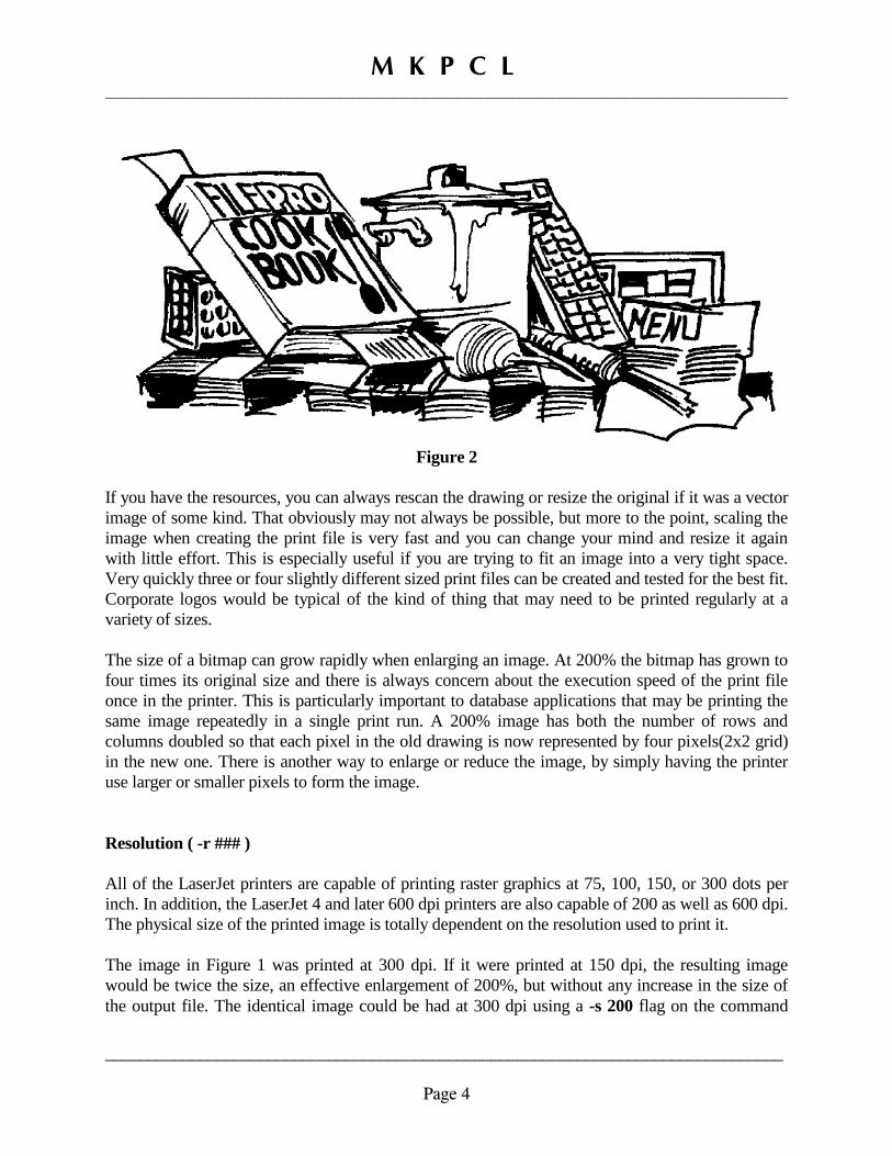
By contrast, the image in Figure 2 is the same drawing except that the scaling has now enlarged the
drawing to 175% of the original size. Again, compare the enlargement to the original and you will
see that it stands up pretty well. Its command line was mkpcl -s 175 inputfile outputfile. Enlarged
images compress very well. Although the 175% magnification more than tripled the amount of
image data, the print file only grew by about one third.
M K P C L _________________________________________________________________
_______________________________________________________________________________
Page 4
Figure 2
If you have the resources, you can always rescan the drawing or resize the original if it was a vector
image of some kind. That obviously may not always be possible, but more to the point, scaling the
image when creating the print file is very fast and you can change your mind and resize it again
with little effort. This is especially useful if you are trying to fit an image into a very tight space.
Very quickly three or four slightly different sized print files can be created and tested for the best fit.
Corporate logos would be typical of the kind of thing that may need to be printed regularly at a
variety of sizes.
The size of a bitmap can grow rapidly when enlarging an image. At 200% the bitmap has grown to
four times its original size and there is always concern about the execution speed of the print file
once in the printer. This is particularly important to database applications that may be printing the
same image repeatedly in a single print run. A 200% image has both the number of rows and
columns doubled so that each pixel in the old drawing is now represented by four pixels(2x2 grid)
in the new one. There is another way to enlarge or reduce the image, by simply having the printer
use larger or smaller pixels to form the image.
Resolution ( -r ### )
All of the LaserJet printers are capable of printing raster graphics at 75, 100, 150, or 300 dots per
inch. In addition, the LaserJet 4 and later 600 dpi printers are also capable of 200 as well as 600 dpi.
The physical size of the printed image is totally dependent on the resolution used to print it.
The image in Figure 1 was printed at 300 dpi. If it were printed at 150 dpi, the resulting image
would be twice the size, an effective enlargement of 200%, but without any increase in the size of
the output file. The identical image could be had at 300 dpi using a -s 200 flag on the command

M K P C L _________________________________________________________________
_______________________________________________________________________________
Page 5
line, except the print file would be four times the size. If it works out that a change in the printing
resolution will create the exact size that is needed, then a resolution change would generally be
preferable to using a scale command. You would either get a smaller file in the case of an
enlargement or finer detail in a reduction. On the other hand, printer resolution isn't a terribly
practical means of image scaling because the choices are so limited, which means that most of the
time none of the available resolutions would produce the wanted image size.
Figure 3 – Resolution Variations
The effect of a change in printer resolution is demonstrated in Figure 3 where the identical bitmap
image is printed at 600, 300, 200, 150 dpi on the top row and at 100 and 75 dpi on the bottom row.
This particular logo with its curved lines is a good example to show what can happen to a drawing
when printed at a coarser resolution. The original image was scanned at 300 dpi, so the image
second from the left on the top row represents the original size and resolution. The raggedness that
comes with a lower resolution is quite apparent. Note that this is only a concern when dealing with
diagonal or curved lines.

M K P C L _________________________________________________________________
_______________________________________________________________________________
Page 6
One way to keep curves and diagonals as smooth as possible, assuming a 300 dpi scanner, is to scan
the original at 200% of the size needed for printing, but use 600 dpi when actually printing the
image. Of course a 600 dpi printer is required.
When printing a large raster image or several smaller ones on the same page, there is always the
real danger of running out of printer memory. The situation can be remedied by cutting the
resolution in half; e.g., from 300 to 150, and then using the -s 50 flag on the command line to
preserve the original size. The effect of this is to reduce the required printer memory to one fourth
of what had been needed at the higher resolution.
The program will default to a 300 dpi resolution if the -r flag is absent from the command line. If a
different default resolution is wanted, the environment variable PCLRES can be set to the desired
value. An -r flag on the command line will override the resolution setting in the environment.
Height and Width ( -h ### and/or -w ### )
Rather than specifying the desired image size as a percentage of the original, the user can supply an
absolute width or height on the command line and the program will make the necessary
calculations, taking into account the resolution, to create the appropriately sized image. Usually, the
-h or -w flags would be mutually exclusive on the command line; i.e., if the width is supplied then
the height is calculated proportionally and vice versa. This is called "isotropic" scaling where units
or dots are the same size both horizontally and vertically.
If both a width and a height are supplied on the command line, then there is a good chance that to fit
the image to the specified rectangle, it will have to be scaled to different proportions on the width
and height. This would be "anisotropic" scaling where the horizontal and vertical units of measure
are different. Basically, the effect is to shrink or stretch the image in one direction or another. This
is shown in Figure 4 where the image on the left side was generated using the command mkpcl -u
px -w 925 inputfile outputfile. The resulting image is 925 dots wide as specified, and the height
scaled to 770 dots. The command mkpcl -u px -w 925 -h 600 inputfile outputfile produced the
corresponding image on the right. The second drawing has not been cropped in the sense of
clipping off part of the image, but rather it has been squeezed together from top to bottom to
conform to the 600 dot height specified on the command line. Depending on how you want to look
at it, you could also say that the 600 dot height was specified and the image width was stretched to
conform to the 925 dot width that was indicated. The scaling of the image height and width are two
completely separate operations internally and one is not dependent on the other. The -u flag will be
explained momentarily.
The default unit of measure used in the argument to the -h or -w flag is the inch, but other units are
available and they are discussed in the description of the -u flag. The argument may contain a

M K P C L _________________________________________________________________
_______________________________________________________________________________
Page 7
decimal point indicating some fractional part of a user unit. However, all measurements are
ultimately converted back to pixels, so to be meaningful the fractional component of the argument
will have to represent a least one pixel.
Figure 4
User Units ( -u ?? )
The unit of measure specified as an argument to the -u flag permits the user to define the image size
in more convenient terms perhaps than printer pixels. This flag only has meaning when used when
specifying an absolute image size on the command line in conjunction with the -h and/or -w flags.
There are six different measuring scales available, each of which has a mnemonic abbreviation that
will be used as the -u flag argument.
1. in Inch
2. px Pixel or printer dot
3. cm Centimeter (Assumes 2.54 cm to the inch)
4. mm Millimeter (Assumes 25.4 mm to the inch)
5. pc Pica (Assumes six picas to the inch exactly)
6. pt Point (Assumes 72 points to the inch exactly)

M K P C L _________________________________________________________________
_______________________________________________________________________________
Page 8
If the -u flag is absent from the command line, the program will default to using the inch as the unit
of measure. Note that the size of a pixel is determined by the resolution used and thus can vary from
one invocation of the program to the next, whereas all of the other scales are absolute fractions of
an inch. The term pixel is used here to avoid confusion with the term dot that may be used in the
same frame of reference when defining a cursor location. Traditionally, there were 300 dots to the
inch and we don't want to confuse that with the image pixel which may or may not be 300 dpi.
For an image 4.25 inches wide, type mkpcl -w 4.25 inputfile outputfile
For an image 10 cm wide, type mkpcl -u cm -w 10 inputfile outputfile
Substitute the appropriate mnemonic on the command line for the other measuring scales. The
program recognizes the environment variable PCLUNIT and it will be recognized as the default
unit of measure when set. To make the centimeter the default, at the prompt...
UNIX users type PCLUNIT=cm; export PCLUNIT
DOS users type set PCLUNIT=cm
An argument to the -u flag on the command line will override the environment setting.
Border ( -b )
This flag simply instructs the program to make all the perimeter pixels of the image black. This can
greatly enhance the "look" of a grayscale image and is useful to determine the limits of a scanned
image that has a white surround. To add the border to the image put the -b flag on the command
line without argument. Figure 5 was created with mkpcl -b inputfile outputfile.
Figure 5 – Adding a border
M K P C L _________________________________________________________________
_______________________________________________________________________________
Page 9
Grayscale Tone Manipulation
Unlike the black & white two color images we have looked at thus far, grayscale files are far more
susceptible to differences in resolution, printer density settings, and other variations from printer to
printer. The same image will probably be darker if printed at 600 dpi vs. 300 dpi on the same
printer. Printer dots tend to "bleed" some and this is proportionately greater at higher resolutions.
Mkpcl offers some command line options to modify the printed output.
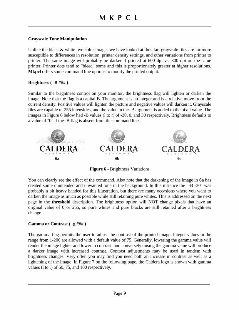
Brightness ( -B ### )
Similar to the brightness control on your monitor, the brightness flag will lighten or darken the
image. Note that the flag is a capital B. The argument is an integer and is a relative move from the
current density. Positive values will lighten the picture and negative values will darken it. Grayscale
files are capable of 255 intensities, and the value in the -B argument is added to the pixel value. The
images in Figure 6 below had -B values (l to r) of -30, 0, and 30 respectively. Brightness defaults to
a value of "0" if the -B flag is absent from the command line.
6a 6b 6c
Figure 6 - Brightness Variations
You can clearly see the effect of the command. Also note that the darkening of the image in 6a has
created some unintended and unwanted tone in the background. In this instance the "-B -30" was
probably a bit heavy handed for this illustration, but there are many occasions where you want to
darken the image as much as possible while still retaining pure whites. This is addressed on the next
page in the threshold description. The brightness option will NOT change pixels that have an
original value of 0 or 255, so pure whites and pure blacks are still retained after a brightness
change.
Gamma or Contrast ( -g ### )
The gamma flag permits the user to adjust the contrast of the printed image. Integer values in the
range from 1-200 are allowed with a default value of 75. Generally, lowering the gamma value will
render the image lighter and lower in contrast, and conversely raising the gamma value will produce
a darker image with increased contrast. Contrast adjustments may be used in tandem with
brightness changes. Very often you may find you need both an increase in contrast as well as a
lightening of the image. In Figure 7 on the following page, the Caldera logo is shown with gamma
values (l to r) of 50, 75, and 100 respectively.

M K P C L _________________________________________________________________
_______________________________________________________________________________
Page 10
7a 7b 7c
Figure 7 - Gamma Variations
Again, the effect is readily apparent. Some color images may require a significant increase in
contrast when rendered in grayscale. The color image can derive its perceived "bounce" from
contrasting colors where the grayscale image must rely entirely on tonal variations.
Threshold ( -H ###, -S ###)
The threshold command can specify two different pixel intensities. There is a "highlight" as well as
a "shadow" level, defined by the -H and -S flags respectively. The highlight threshold defines a
pixel value, and any pixel in the image with a greater value will be "promoted" to pure white(255).
Similarly, the shadow threshold also defines a pixel value, but values below it will be demoted to
pure black(0). Referring back now to the dark image in Figure 6a, it is shown again in Figure 8a. If
we run the same mkpcl command but add the -H flag to the command line, we can "restore" the
white pixels back to their original values without affecting the darker pixels. In this example we had
lowered the value of all pixels by 30 points, so considering that the maximum pixel value is 255,
lets set our threshold to 220 and see if that cleans up the background. See Figure 8b.
8a 8b
Figure 8 – Highlight Threshold
This can very useful when working with ballpoint pen signatures that have been scanned in color.
Ballpoint may not reproduce very well, as the line work tends to be broken and uneven. You can
easily darken the signature and then clean up the background by setting a highlight threshold. While
maybe not as common, a shadow threshold may save some thin lines or small text in an image that
has been lightened. It may take a bit of trial and error to establish the needed value. If you are one
point too high in the white threshold value, you get no effect at all. If you are too low you modify
pixels that you didn't want to. The inverse applies when working with a shadow threshold. The
main thing is to set your threshold right at the breakpoint so you don't change any pixels
unnecessarily. Program default values are 255 for the highlight threshold and 0 for the shadow
threshold.(No effect for either)

M K P C L _________________________________________________________________
_______________________________________________________________________________
Page 11
Trim ( -t ), Trim Threshold ( -T ### )
The trim option, when invoked by the -t flag on the command line, will "trim off" any surrounding
"white" overscan from the image if it is there. Bytes are physically deleted from the output file if
there is extra white around the image.
Aside from removing some "excess baggage" from the file, the trimmed image is potentially easier
to size to a specific dimension than its untrimmed counterpart. No argument is required to the flag
on the command line. The command mkpcl -t -b inputfile outputfile produced Figure 9 below.
Compare that to the untrimmed version in Figure 5. The border has been included for comparison
purposes only. Note that when the -t flag is used together with the -w or -h flags, the image will be
sized based on the trimmed image; i.e., the image is trimmed before any size calculations are made.
Figure 9 – Trimming the image
The -T option is used in conjunction with the -t flag to set a trim threshold on grayscale images;
i.e., both the -t and -T ### are used together on the command line. The trim function processes the
original image before any highlight adjustments are made and likely would not be effective on a
grayscale image because the brightest tone or intensity in the image is something less than pure
white. Similar to the highlight threshold command, the argument to the -T flag defines the pixel
intensity considered pure white for trim purposes. This has no effect on the rendering of the image
itself, just the criterion used to trim off excess background. This is very useful when working with
signatures that have been scanned in color. Signatures in particular are much easier to position and
size with all the overscan removed. Invariably the background tone is something "less" than white
and it will not trim with the -t flag alone; however, the addition of -T 210 to the command line may
do the trick. A little experimentation will give you a feel for the needed value. For example try
mkpcl -t -T210 -b inputfile outputfile. If the border still includes background beyond the
signature on any of the four sides, use a lower threshold and try again. Of course, you would
remove the -b from the command line once the result was satisfactory. Once in a while you will
find a "blob" of some kind in the overscan area that prevents the trim function from operating as
wanted. In that case, take the original file into a "paint" program and erase the offending mark.
M K P C L _________________________________________________________________
_______________________________________________________________________________
Page 12
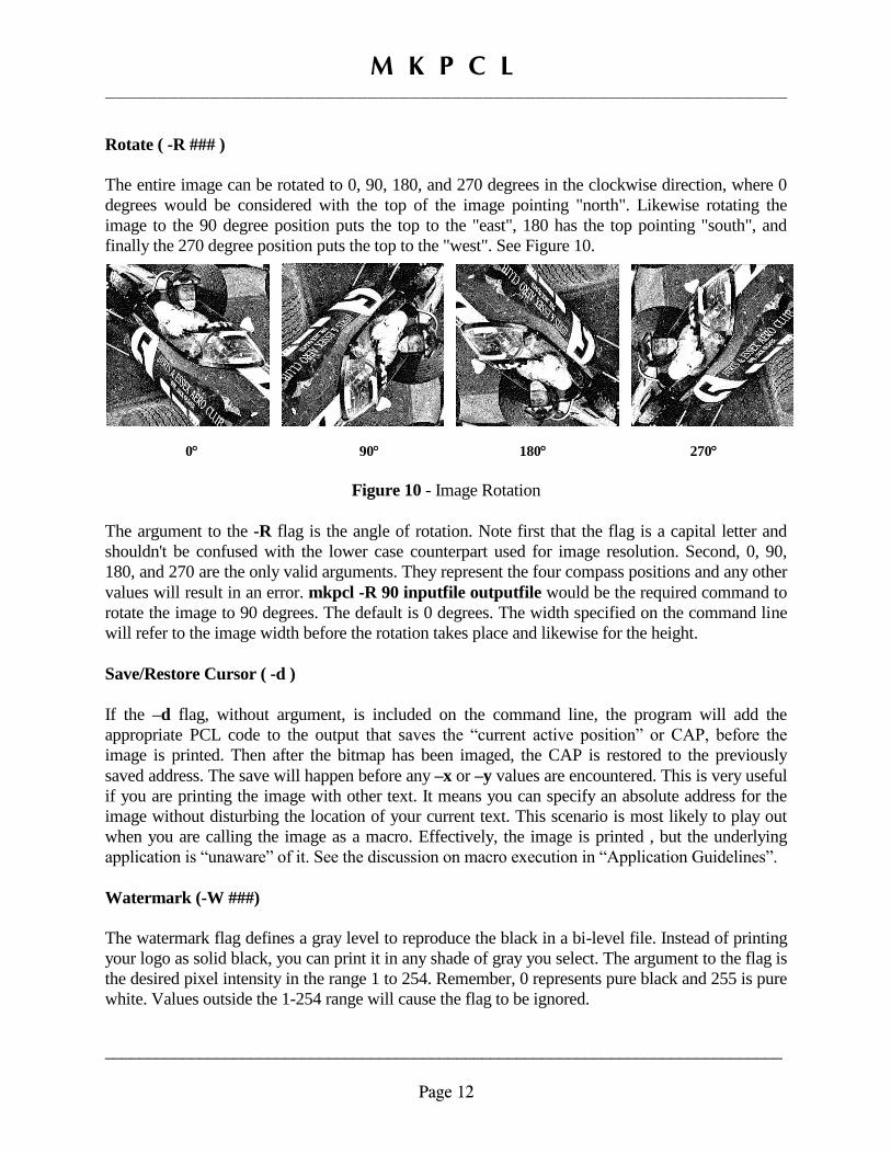
Rotate ( -R ### )
The entire image can be rotated to 0, 90, 180, and 270 degrees in the clockwise direction, where 0
degrees would be considered with the top of the image pointing "north". Likewise rotating the
image to the 90 degree position puts the top to the "east", 180 has the top pointing "south", and
finally the 270 degree position puts the top to the "west". See Figure 10.
0 90 180 270
Figure 10 - Image Rotation
The argument to the -R flag is the angle of rotation. Note first that the flag is a capital letter and
shouldn't be confused with the lower case counterpart used for image resolution. Second, 0, 90,
180, and 270 are the only valid arguments. They represent the four compass positions and any other
values will result in an error. mkpcl -R 90 inputfile outputfile would be the required command to
rotate the image to 90 degrees. The default is 0 degrees. The width specified on the command line
will refer to the image width before the rotation takes place and likewise for the height.
Save/Restore Cursor ( -d )
If the –d flag, without argument, is included on the command line, the program will add the
appropriate PCL code to the output that saves the “current active position” or CAP, before the
image is printed. Then after the bitmap has been imaged, the CAP is restored to the previously
saved address. The save will happen before any –x or –y values are encountered. This is very useful
if you are printing the image with other text. It means you can specify an absolute address for the
image without disturbing the location of your current text. This scenario is most likely to play out
when you are calling the image as a macro. Effectively, the image is printed , but the underlying
application is “unaware” of it. See the discussion on macro execution in “Application Guidelines”.
Watermark (-W ###)
The watermark flag defines a gray level to reproduce the black in a bi-level file. Instead of printing
your logo as solid black, you can print it in any shade of gray you select. The argument to the flag is
the desired pixel intensity in the range 1 to 254. Remember, 0 represents pure black and 255 is pure
white. Values outside the 1-254 range will cause the flag to be ignored.
M K P C L _________________________________________________________________
_______________________________________________________________________________
Page 13
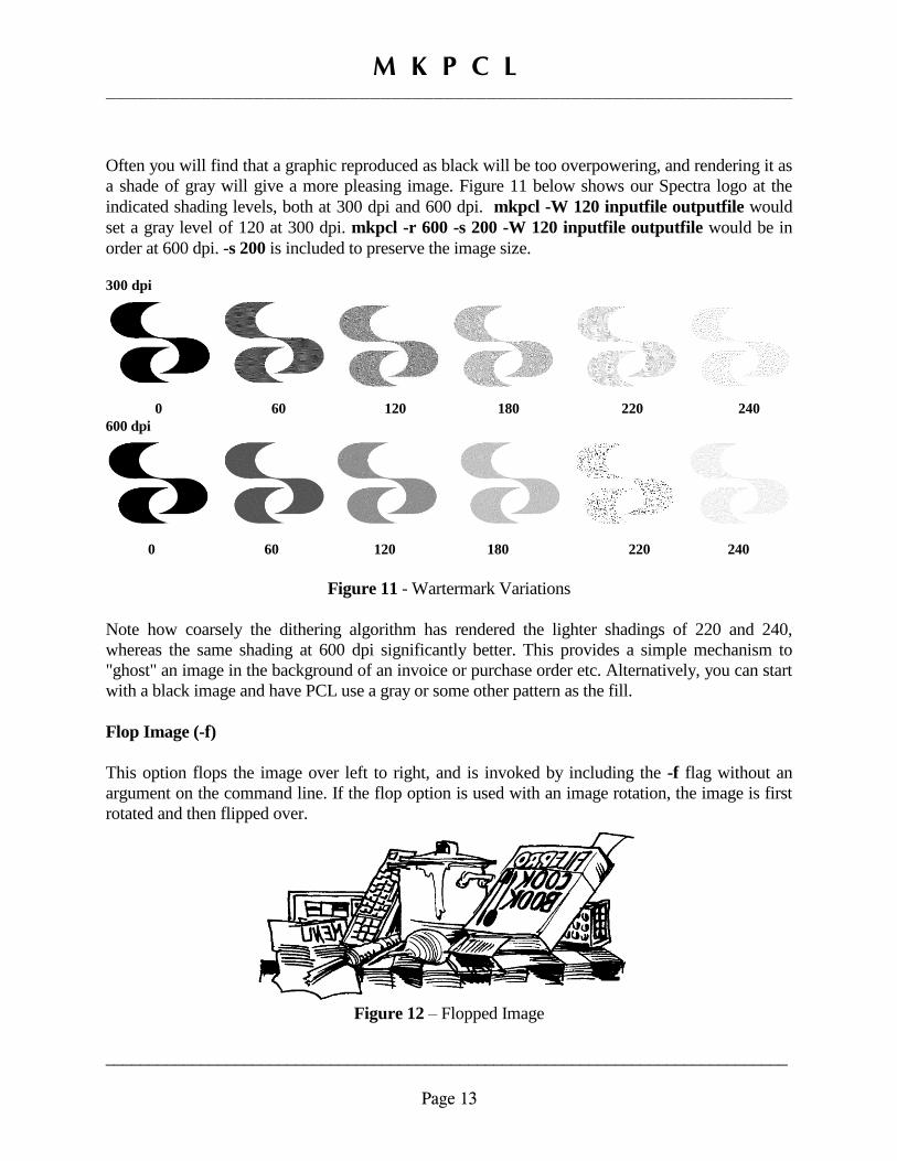
Often you will find that a graphic reproduced as black will be too overpowering, and rendering it as
a shade of gray will give a more pleasing image. Figure 11 below shows our Spectra logo at the
indicated shading levels, both at 300 dpi and 600 dpi. mkpcl -W 120 inputfile outputfile would
set a gray level of 120 at 300 dpi. mkpcl -r 600 -s 200 -W 120 inputfile outputfile would be in
order at 600 dpi. -s 200 is included to preserve the image size.
300 dpi
0 60 120 180 220 240
600 dpi
0 60 120 180 220 240
Figure 11 - Wartermark Variations
Note how coarsely the dithering algorithm has rendered the lighter shadings of 220 and 240,
whereas the same shading at 600 dpi significantly better. This provides a simple mechanism to
"ghost" an image in the background of an invoice or purchase order etc. Alternatively, you can start
with a black image and have PCL use a gray or some other pattern as the fill.
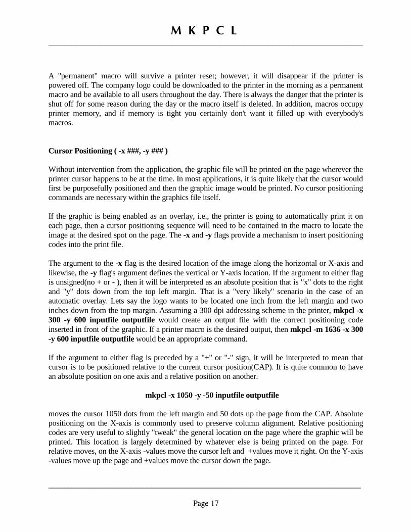
Flop Image (-f)
This option flops the image over left to right, and is invoked by including the -f flag without an
argument on the command line. If the flop option is used with an image rotation, the image is first
rotated and then flipped over.
Figure 12 – Flopped Image

M K P C L _________________________________________________________________
_______________________________________________________________________________
Page 14
Invert Image ( -i )
The invert option reverses the state of each bit in the image, effectively creating a negative of the
original. If the -i flag is present on the command line the image will be inverted. This option may be
more useful than would be immediately apparent primarily because bitmap files are typically
written for video display where a bit that is "on" will display as white, just the opposite of the
printer's behavior. Programs like mkpcl normally invert the image as a matter of course.
Figure 13 – Inverted image
When the -i flag is present on the command line, the image is inverted before any trimming of the
image that may be called for. Image inversion directly affects the "trimability" of any image, and
any image that would trim without inversion will not trim with it.
Crop Image ( -C ###,###,###,### )
The -C option crops the image per the user's specifications. The flag takes four comma separated
arguments that are the desired coordinates, in pixels, that represent the area of interest of the image
in the form -C x-begin,x-end,y-begin,y-end. No spaces are permitted within the argument. The
values are in pixels measuring from the top left of the image. Consider the image to be a two
dimensional array of pixels. We can specify the desired crop area by defining the beginning column
on the left followed by the ending column on the right and then similarly the first and last row. The
first element on either axis is 1.
For example, assume our original BMP is 1200 pixels wide by 700 pixels high. If we want to crop
out of that pixels 230-1050 on the X-axis and rows 40-640 on the Y-axis, the command mkpcl -C
230,1050,40,640 inputfile outputfile would produce the desired output. To establish the desired
coordinates, first print out a copy of the uncropped image on the printer at 300 dpi, the mkpcl
default. Issue mkpcl inputfile outputfile and then print the output file. Print the file included in the
distribution named "ruler.pcl", a ruler with a 300 dpi measuring scale. With the 300 dpi ruler you
can very quickly establish the crop parameters. Laminate and trim the ruler if you can. All
subsequent sizing of the image is based on the crop and not the original.

M K P C L _________________________________________________________________
_______________________________________________________________________________
Page 15
Color Index ( -I ## )
It is possible with a PCL5 color printer to print a monochrome image in a color other than black.
Note that this includes all of the PCL5 color LaserJets and all of the PCL5 DeskJet printers. These
DeskJets include the 2250, 2280, 2300. This will NOT work on the PCL3 DeskJets which includes
the vast majority of HP inkjet printers.
Included in the files in the distribution is ‘colors.pcl’ which is reproduced in Figure 15 below. Print
the file on your PCL5 color printer. It is shown here purely for reference and any judgment of color
fidelity and accuracy should be made from your printed copy. In any case you will see that the sheet
contains 100 copies of our Spectra logo, individually numbered 0-99. There are 10 different colors,
each at 10 different densities. The number below each logo is the argument required for the –C flag
on the command line.
Figure 15 – MKPCL Color Indexes
mkpcl –I 57 inputfile outputfile would produce a green image similar to logo 57 above. Of course
the color accuracy would be 100% when compared to the color sheet that you had printed for
reference. This could be an excellent method for creating watermarks. If you want to make a tinted
watermark, use one of the lighter colors here WITHOUT the –W flag that you would use in black
and white. If you need to reproduce an image that is monochrome, but a color, there are immense
savings in image size printing it this way rather than as a full color image .

M K P C L _________________________________________________________________
_______________________________________________________________________________
Page 16
Limit ( -L ###.##,###.## )
The limit option came as the result of a customer request. It specifies two dimensions in the form -
L maxwidth,maxheight. This represents the maximum size the image is to be in either direction;
i.e., if the image is sized to maxwidth and the height scales to greater than maxheight, then it will
be resized to fit the depth with a correspondingly narrower width. The parameters are comma
separated and no spaces are allowed. The values are stated in user units and fractional components
are permitted where applicable.
Given a 2.75 wide x 1.75 inch high area printing, mkpcl -u in -L 2.75,1.75 inputfile outputfile
will always produce an output image that fits the allocated area, so it could be run from a script and
process a number of originals without operator intervention. If you have to contend with a variety of
sizes and shapes of originals, mkpcl will insure the image fits within the limits of the defined box.
Printer Macro ( -m ###, -p )
The output file can be formatted for downloading to the printer as a macro and then later executed
by the application or enabled as an automatic overlay. See the "macro example" later in this manual
for macro details. To create a macro file, simply add the -m flag to the command line with an
integer from 1 to 32767 as the argument. This number will be the Macro ID unique to this macro
that is referenced later when it is run.
For example, mkpcl -m 1636 inputfile outputfile would create a PCL file that would store macro
number 1636 in the printer's memory once it was downloaded. Then, at the appropriate time the
underlying application would issue the "execute macro 1636" command at which time the graphic
would be integrated into the current page being printed. If the macro option is used the following is
sent to the file, using -m 1636 cited as the example.
1. Delete macro 1636 if it exists
2. Begin definition of macro 1636
3. Image data
4. End macro 1636 definition
Without the -m flag, only the image data(3) would go into the output file, and with it commands 1,
2, and 4 are added. Once downloaded, the macro will exist in the printer until it is powered off or
reset. A normal print job would reset the printer when finished and the macro would cease to exist.
If the -p flag is added to the command line, then one more command is tagged on to the end of the
file. The -p flag is ignored in the absence of the -m flag.
5. Make macro 1636 permanent
M K P C L _________________________________________________________________
_______________________________________________________________________________
Page 17
A "permanent" macro will survive a printer reset; however, it will disappear if the printer is
powered off. The company logo could be downloaded to the printer in the morning as a permanent
macro and be available to all users throughout the day. There is always the danger that the printer is
shut off for some reason during the day or the macro itself is deleted. In addition, macros occupy
printer memory, and if memory is tight you certainly don't want it filled up with everybody's
macros.
Cursor Positioning ( -x ###, -y ### )
Without intervention from the application, the graphic file will be printed on the page wherever the
printer cursor happens to be at the time. In most applications, it is quite likely that the cursor would
first be purposefully positioned and then the graphic image would be printed. No cursor positioning
commands are necessary within the graphics file itself.
If the graphic is being enabled as an overlay, i.e., the printer is going to automatically print it on
each page, then a cursor positioning sequence will need to be contained in the macro to locate the
image at the desired spot on the page. The -x and -y flags provide a mechanism to insert positioning
codes into the print file.
The argument to the -x flag is the desired location of the image along the horizontal or X-axis and
likewise, the -y flag's argument defines the vertical or Y-axis location. If the argument to either flag
is unsigned(no + or - ), then it will be interpreted as an absolute position that is "x" dots to the right
and "y" dots down from the top left margin. That is a "very likely" scenario in the case of an
automatic overlay. Lets say the logo wants to be located one inch from the left margin and two
inches down from the top margin. Assuming a 300 dpi addressing scheme in the printer, mkpcl -x
300 -y 600 inputfile outputfile would create an output file with the correct positioning code
inserted in front of the graphic. If a printer macro is the desired output, then mkpcl -m 1636 -x 300
-y 600 inputfile outputfile would be an appropriate command.
If the argument to either flag is preceded by a "+" or "-" sign, it will be interpreted to mean that
cursor is to be positioned relative to the current cursor position(CAP). It is quite common to have
an absolute position on one axis and a relative position on another.
mkpcl -x 1050 -y -50 inputfile outputfile
moves the cursor 1050 dots from the left margin and 50 dots up the page from the CAP. Absolute
positioning on the X-axis is commonly used to preserve column alignment. Relative positioning
codes are very useful to slightly "tweak" the general location on the page where the graphic will be
printed. This location is largely determined by whatever else is being printed on the page. For
relative moves, on the X-axis -values move the cursor left and +values move it right. On the Y-axis
-values move up the page and +values move the cursor down the page.

M K P C L _________________________________________________________________
_______________________________________________________________________________
Page 18
Presentation Mode ( -l # )
Raster graphics are printed in portrait orientation, regardless of the orientation of the logical page.
So if you print an image on a landscape page, without intervention, the image would still print in
portrait orientation appearing “sideways” on the landscape page. PCL code can be added to the
stream that instructs the printer to rotate the image to the current orientation automatically, or the
image can be rotated so when it is printed as portrait, it still "reads" properly when viewing the
landscape page. It is most efficient for the printer if an image is printed in portrait orientation.
The -l (ell) flag can be included on the command line to let you choose the preferred behavior. Only
values of 0 or 1 are permitted. An argument of 0 will leave the image untouched and a 1 will cause
the image to follow the orientation. The default is 1 , which means that it is unlikely you would ever
have a problem if you ignored this flag altogether.
Runtime Display (-v #)
At runtime, various messages are displayed on the screen that track the program’s execution
progress. This is pretty standard and what we expect. For most users this flag can probably be
ignored. The text below shows a typical display.
# mkpcl -c4 -s 135 logo.bmp logo.pcl Reading Source File... logo.bmp logo.pcl Current Width Width at 135% 408 Dots 551 Dots Current Height Height at 134% 321 Dots 433 Dots Scaling Image... Dithering... Generating output... 100% Complete Sun Oct 2 11:13:55 2005 mkpcl -c4 -s 135 logo.bmp logo.pcl No Errors - Normal program termination! #
For reference, the command line is shown at the top. The information displayed is determined by
the command line contents. Input and output image sizes are shown first, followed by the applicable
program functions as they are executed. This culminates with “Generating Output” that builds to
100%. The output file is complete at this point. The final three lines contain a timestamp, a copy of
the command line, and a message confirming the successful execution of the program. If the
program encounters an error while running, an error message will be shown in the third line.
M K P C L _________________________________________________________________
_______________________________________________________________________________
Page 19
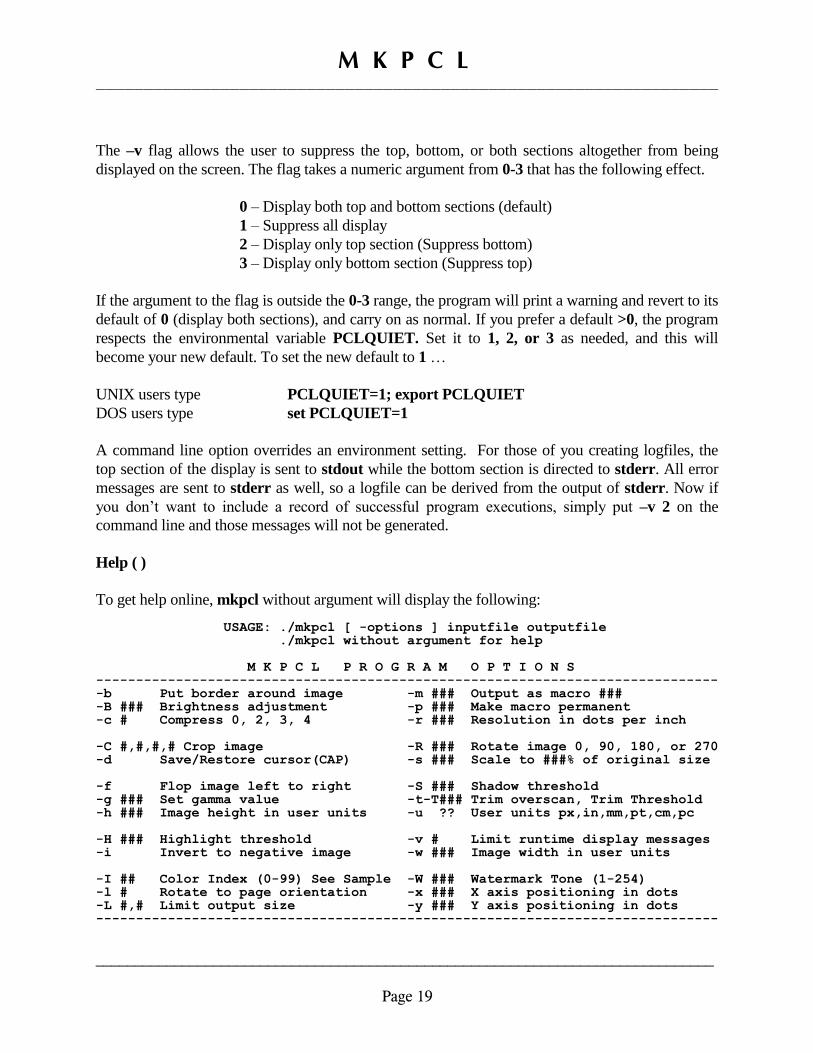
The –v flag allows the user to suppress the top, bottom, or both sections altogether from being
displayed on the screen. The flag takes a numeric argument from 0-3 that has the following effect.
0 – Display both top and bottom sections (default)
1 – Suppress all display
2 – Display only top section (Suppress bottom)
3 – Display only bottom section (Suppress top)
If the argument to the flag is outside the 0-3 range, the program will print a warning and revert to its
default of 0 (display both sections), and carry on as normal. If you prefer a default >0, the program
respects the environmental variable PCLQUIET. Set it to 1, 2, or 3 as needed, and this will
become your new default. To set the new default to 1 …
UNIX users type PCLQUIET=1; export PCLQUIET
DOS users type set PCLQUIET=1
A command line option overrides an environment setting. For those of you creating logfiles, the
top section of the display is sent to stdout while the bottom section is directed to stderr. All error
messages are sent to stderr as well, so a logfile can be derived from the output of stderr. Now if
you don’t want to include a record of successful program executions, simply put –v 2 on the
command line and those messages will not be generated.
Help ( )
To get help online, mkpcl without argument will display the following: USAGE: ./mkpcl [ -options ] inputfile outputfile ./mkpcl without argument for help M K P C L P R O G R A M O P T I O N S ------------------------------------------------------------------------------ -b Put border around image -m ### Output as macro ### -B ### Brightness adjustment -p ### Make macro permanent -c # Compress 0, 2, 3, 4 -r ### Resolution in dots per inch -C #,#,#,# Crop image -R ### Rotate image 0, 90, 180, or 270 -d Save/Restore cursor(CAP) -s ### Scale to ###% of original size -f Flop image left to right -S ### Shadow threshold -g ### Set gamma value -t-T### Trim overscan, Trim Threshold -h ### Image height in user units -u ?? User units px,in,mm,pt,cm,pc -H ### Highlight threshold -v # Limit runtime display messages -i Invert to negative image -w ### Image width in user units -I ## Color Index (0-99) See Sample -W ### Watermark Tone (1-254) -l # Rotate to page orientation -x ### X axis positioning in dots -L #,# Limit output size -y ### Y axis positioning in dots ------------------------------------------------------------------------------
M K P C L _________________________________________________________________
_______________________________________________________________________________
Page 20
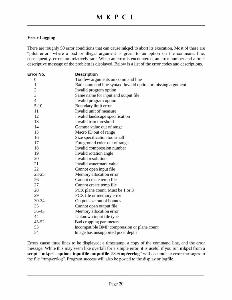
Error Logging
There are roughly 50 error conditions that can cause mkpcl to abort its execution. Most of these are
“pilot error” where a bad or illegal argument is given to an option on the command line;
consequently, errors are relatively rare. When an error is encountered, an error number and a brief
descriptive message of the problem is displayed. Below is a list of the error codes and descriptions.
Error No. Description
0 Too few arguments on command line
1 Bad command line syntax. Invalid option or missing argument
2 Invalid program option
3 Same name for input and output file
4 Invalid program option
5-10 Boundary limit error
11 Invalid unit of measure
12 Invalid landscape specification
13 Invalid trim threshold
14 Gamma value out of range
15 Macro ID out of range
16 Size specification too small
17 Foreground color out of range
18 Invalid compression number
19 Invalid rotation angle
20 Invalid resolution
21 Invalid watermark value
22 Cannot open input file
23-25 Memory allocation error
26 Cannot create temp file
27 Cannot create temp file
28 PCX plane count. Must be 1 or 3
29 PCX file or memory error
30-34 Output size out of bounds
35 Cannot open output file
36-43 Memory allocation error
44 Unknown input file type
45-52 Bad cropping parameters
53 Incompatible BMP compression or plane count
54 Image has unsupported pixel depth
Errors cause three lines to be displayed; a timestamp, a copy of the command line, and the error
message. While this may seem like overkill for a simple error, it is useful if you run mkpcl from a
script. “mkpcl –options inputfile outputfile 2>>/tmp/errlog” will accumulate error messages to
the file “/tmp/errlog”. Program success will also be posted to the display or logfile.

M K P C L _________________________________________________________________
_______________________________________________________________________________
Page 21
Application Guidelines
A raster file is either imaged by the printer immediately as the data is received, or it is downloaded
to the printer as a macro, and is then processed at some later time. In most instances it is not very
practical to download a file in the middle of the data stream. Further, many applications do not
provide the functionality to make timely downloads to the printer. Ideally, all necessary macros
would be downloaded to the printer at the beginning of the job.
A macro provides alternatives for the application to utilize the bitmap, and would most likely be the
preferred approach. In the macro scenario, the image is sent to the printer with its embedded unique
Macro ID. This download of the image to the printer can happen at the beginning of the print job or
it could be first thing in the morning for a job that is going to be printed sometime later in the day.
If the macro was defined as permanent, then only a loss of power to the printer or an explicit delete
or replace macro command will change the macro's status. In the worst case where the application
provides no way to send a file to the printer on demand, you can simply use your standard "print"
command to direct the macro to the printer before your application is started. Nothing will
physically print at this point.
Once the macro has been sent to the printer, your application only needs to send a short PCL
command to either execute the macro or enable it for automatic overlay. We will look at each of
these alternatives in detail in a moment. Your application must have the facility to permit PCL code
to be inserted in the middle of the job. In addition, as part of the PCL code, you have to be able to
enter the "escape" character, chr$(27) in basic, 0x1B in hex, \033 in octal, and of course 27 in
decimal. In the examples here, the "escape" is shown simply as <esc> in the code, but it still refers
to the real escape character. Fortunately, the balance of the PCL code is all ASCII characters. A
macro can contain any valid PCL code as well as bitmaps.
From this point forward it is assumed that macro 1636 has already been downloaded and was
declared as permanent when mkpcl created the macro. As long as they each have a unique ID,
several macros can be resident in the printer simultaneously, largely limited only by the amount of
printer memory.
Automatic Overlay
When enabled as an automatic overlay, the macro code will be run as the very last thing before the
page is actually printed and ejected from the printer. To enable a macro as automatic, we need to
insert somewhere on the page <esc>&f###y4X, where ### represents the Macro ID number that
was assigned when mkpcl was run. So in the example at hand we would issue <esc>&f1636y4X.
Once enabled the overlay will be run on every page until the overlay is explicitly disabled, a
different macro is enabled, or the printer is reset. To disable the overlay, issue <esc>&f5X anytime.
The ID is not required to disable, as only one macro can be enabled at any given time.

M K P C L _________________________________________________________________
_______________________________________________________________________________
Page 22
Because the overlay is run after the PCL page has been imaged, you must supply PCL coordinates
to position the bitmap on the page. Do this with the -x and -y flags on the mkpcl command line
when the macro is created. One advantage of the automatic overlay is that you needn't concern
yourself with the cursor's position once the image has been laid down as the cursor is reset when the
page is printed. The overlay is particularly ideal where you have a logo or some other item that is
displayed at the same location on every page.
Macro Execution
When a macro is "executed", it is immediately run at the location where the execute command was
encountered on the page. A macro is executed with the command <esc>&f###y3X where ### is
the macro ID, thus the command for the image at hand would be <esc>&f1636y3X. Once the
macro has been run, the cursor remains at the bottom left of the image, and this has probably put the
cursor "out of sync" with the application. What we can do is save the cursor address before the
image is laid down, and then restore the cursor back to its original location when done. Our
application is none the wiser. The command <esc>&f0S saves the current cursor location and
<esc>&f1S restores the cursor to the last previously saved address. This means that you could
embed X,Y coordinates in the bitmap itself or you could supply the positioning codes from within
your application.
If macro 1636 contains X,Y code within, <esc>&f0S<esc>&f1636y3X<esc>&f1S would save the
cursor, run the macro, and restore the cursor back to the point we started at. Let's say we wanted to
print at location 400X 1200Y. Rather than have the XY code in the macro we could position it
within the application, but remember to save the cursor beforehand. In this case we could issue
<esc>&f0S<esc>*p400x1200Y<esc>&f1636y3X<esc>&f1S and the image would be positioned
as desired. Sometimes the print location is determined by the data on the page and can only be
established at runtime. For example, this could be a signature at the end of some text of
undetermined length. In this case we probably always want to print at the same X location, but the
desired Y location is relative to the end of text. If our PCL command is issued right at the "end of
text", we can use a relative positioning code for the Y-axis.
The code <esc>&f0S<esc>*p400x+50Y<esc>&f1636y3X<esc>&f1S will position the image 50
dots below the point the macro call was encountered with the cursor eventually restored to the
calling point.
Macros can be nested, so if you have a macro to overlay an invoice form, you would have the
invoice macro execute the logo macro as part of the form. The logo macro would have no internal
positioning codes. This way, a single logo macro could be used on any number of forms and only
require a single download. Also, an image can be repeated on the same page just by executing the
macro at different locations. An automatic overlay that contains all of the static information on the
printed page can immensely reduce the complexity of the application as the overlay might be able
to relieve the application of font changes and other PCL overhead.

M K P C L _________________________________________________________________
_______________________________________________________________________________
Page 23
A Macro Example
To tie all of this together, we will create a letterhead macro that will be used as an automatic
overlay. The entire demonstration will require a total of three files.
1. lhead.mac the main letterhead macro
2. logo.mac a logo macro executed by lhead.mac
3. demo the application that calls lhead.mac
Although it is not shown at actual size, below is a copy of the completed macro. You can see that
there are three elements, the logo, some text, and a line.
The entire operation is controlled by the "lhead.mac" file. With the exception of the logo, all of the
PCL code in the macro can be entered with a text editor. The escape character is shown as ^[ in the
listing below. This is how it is represented by the vi editor. Remember that this is a single character
in the file. The line numbers are for display here and are not part of the file.
1. ^[&f1636y0X^[&l6d0e66F^[(s1p20v0s0b4197T 2. ^[*p475x285YSpectra Colour Services Ltd.^[(s12V
3. ^[*p475x352Y Box 2 – 10688 King George Hwy, Surrey... 4. ^[*p300x385Y^[*c1960a7bP 5. ^[*p60x85Y^[&f100y3X^[&f1X^[&f1636y10X
The first line begins ^[&f1636y0X. This is a begin macro definition command. The value preceding
the "y" is the macro ID and 0X indicates begin macro definition. Next is a page formatting
command. The "0e" in the middle of the string specifies there is NO top margin. This format is only
for the macro itself, and not the page format for the application that will later use the macro. This is
done so we can print overlay items in the application's margins if desired. The final item on the line
is the sequence to call up 20 pt. Garamond for the "company name".
Line 2 positions the cursor, prints the company name, and reduces the point size to 12 pt for the
address and phone numbers which are positioned and printed on the third line. Some of the actual
address text has been deleted here to make it fit on one line. The complete text is in the lhead.mac
file. The fourth line positions and prints the horizontal line with a PCL sequence.
Finally, on the fifth line, the logo is positioned, and then "printed" by executing macro 100, which
we will create in a moment. This is followed by ^[&f1X which is the "end macro definition"
command. The last sequence declares macro 1636 as permanent.

M K P C L _________________________________________________________________
_______________________________________________________________________________
Page 24
Logo Macro
Create the logo macro with mkpcl using the supplied logo.bmp file as the source. Enter the
command as follows:
mkpcl –c 4 -t -m 100 -p logo.bmp logo.mac
This will create "logo.mac" with a macro ID of "100" and will be marked as permanent when it is
sent to the printer.
Test File
Using your text editor, enter the following into a file called "demo":
^[&f1636y4X ^[*p825x1200YTest of letterhead macro.^L
Remember that the ^[ represents the escape character. Save the file and we can go on to test the
macro. The first line enables macro 1636 for overlay, and the second is just frivolous text with
associated positioning code. At the end there is a formfeed, shown as ^L. You would enter ^L in
"vi", but do whatever you need to with your editor to get char 12.
Putting it to Work
Direct both logo.mac and lhead.mac to your laser printer using the appropriate "print" command for
your computer system. While these macros are in separate files here, several macros could be
contained in a single file, thus requiring only a single download for all of them. Now print the demo
file, and you should have the letterhead nicely printed at the top and the sample text down towards
the center of the page. Change the text and print it again. If you haven't shut off the printer in
between, the letterhead should print again without a reload.
Conclusion
You can create sophisticated applications that require little PCL code to implement. Consider that
you can have several macros downloaded and resident in the printer. Then some logic in the
application can execute the overlay containing the logo or form that is appropriate based on some
criterion contained within the user data. A simple example might be an invoicing routine that
overlays an "invoice" form for positive amounts, but overlays a "credit note" for negative amounts.
Start out with modest goals, and build on it from there. This discussion is largely beyond the scope
of mkpcl itself, which is simply another tool used to achieve your intended goal.
The best way to learn is through experimentation. Because of the flexibility afforded by the PCL
language itself, there is usually more than one way to accomplish your print requirements. There is
a wealth of information in the PCL 5 Technical Reference Manual Set available online from
Hewlett-Packard in PDF format. If you are stuck, send email to [email protected] and
describe what you are trying to do and where you are having a problem.

M K P C L _________________________________________________________________
_______________________________________________________________________________
Page 25
FilePro Usage
Inserting a bitmap graphic into filePro output requires three general steps. First, the CAP must be
moved to the position on the page where the graphic is to be printed. The initial position marks the
top left corner of the bitmap image. Then the file containing the image is sent to the printer, and
finally the CAP may need to be relocated on the page to continue printing the balance of the page.
To position the cursor, simply send the appropriate PCL escape sequence to the printer that sets the
CAP as desired. It is possible that the CAP may already be where you want the image printed by
virtue of having the graphic downloaded at an opportune time in the filePro data stream, although,
that probably isn't practical most of the time. The graphic file itself is sent to the printer using the
"download" feature available in printer maintenance which is implemented as a printer code on the
print code table. You define in printer maintenance a print code in the form
%"pcl_filename"
The quotes are required and the filename can be either a complete path to the file or a relative path
from the 'download' directory. By default the current directory is used but you can change the
default by setting the environment variable PFDLDIR. The print code for the download can be
located anywhere on the output format from the printer's standpoint, however, if the graphic was to
only appear on the first page of the job then the download would have to be executed during the
format init or some other creative method would have to be implemented to insure the file was only
sent to the printer the one time.
Once the printer has imaged the graphic, the cursor remains at the bottom left of the image. In most
cases this will have put the cursor out of sync with the regular filePro data. The most
straightforward approach to restoring the cursor is to simply use PCL codes to save the cursor
address before the graphic is downloaded and then restore the cursor back to that position after it is
printed. An example should make this clear.
Assume that we have created PCL printable file of our logo and it resides in the file logo.pcl that is
located in the default download directory. Further, we would like to print the logo at location 200X
400Y on every page. If print code number 75, for example, is defined as
$1b &f0S $1b *p200x400Y %"logo.pcl" $1b &f1S
you could put print code 75 anywhere on the output format and the logo would be properly
positioned and subsequent filePro data would be located correctly as well. Note that the above code
is what would literally be entered into the print code table and would be defined as non printing or
not requiring a space to be allowed for it. Now an explanation.

M K P C L _________________________________________________________________
_______________________________________________________________________________
Page 26
$1b &f0S is the PCL sequence to store the CAP or to "push" it onto the "stack". Saving the CAP in
itself does not change the CAP.
$1b *p200x400Y moves the CAP to locate the graphic on the page.
%"logo.pcl" downloads the logo.pcl file to the printer. At this point the CAP is at the bottom of
the logo.
$1b &f1S restores the CAP to the address previously saved or "pops" the previous address off the
"stack". At this point the cursor is now located back to where it was before the print code was
encountered so subsequent filePro data will be unaffected by virtue of the logo having been printed.
All of the cursor positioning code can be added to the graphic file itself, thus requiring only the
download command to appear on the print code table. The -x and -y flags can be used in mkpcl for
this purpose. It would need to be wrapped with the save and restore cursor codes, but that is easily
done with the –d flag on the command line. The only drawback to that approach is the file is made
inflexible for other uses. In this regard, though, there is a public domain "vi" clone called "vim" that
has some useful attributes. It has a binary mode and will not swallow 0x00 characters, line lengths
of several megabytes are allowed, and line wrap can be disabled. These three features make minor
surgery on a PCL bitmap very easy. Invoke in binary mode with “vim –b filename”.
You will find that it is most practical to test the positioning codes etc. by editing the file and
printing with the 'lp' command. Put the image into filePro only when you are certain that you have
what you want. It will save you a lot of time in development.
FilePro and PCL Macros
To demonstrate the ease of implementing printer macros with filePro, we will setup the letterhead
macro previously created, for use in any of your output formats. It is assumed that PFDLDIR has
already been set in the environment.
This is short and sweet. First, define a printcode to download lhead.mac and logo.mac to the
printer, let's say code #65. Define it as requiring no space in the first field, and then for the
"business" part of the code enter %"lhead.mac" %"logo.mac". Now quote code 65 as the form
init code on the F8 options page in define output on the target format. This will download the
macros to the printer at the beginning of the job.
All that remains is to put a variable on the output format that enables or disables the macro for
overlay on the page. Call the variable ol(10,*,g) and in processing make the following assignments.
If you want the letterhead to be printed on the current page, set ol=chr("27"){"&f1636y4X". Once
ol has been sent to the printer, the letterhead will appear on every page. To disable the overlay set
ol=chr("27"){"&f5X". Depending on the contents of ol you can elect to print the letterhead or not.
M K P C L _________________________________________________________________
_______________________________________________________________________________
Page 27
There is a good chance that you only want the letterhead on the first page. In the case of a report,
you would need to keep track of the current page number, and then populate the variable as is
appropriate. Once disabled, the overlay will remain disabled until it is explicitly enabled again.
On a full page form, place ol anywhere that is convenient. On a report format put ol somewhere in
the heading and it will only appear once on the page. The variable only needs to be set when you are
changing the state of the overlay. The processing should be designed to make ol null on any page
where you aren't enabling or disabling the overlay.
HP DeskJet Printers
The key to successfully merging graphic images into filePro output formats is maintaining the
correct alignment of the filePro data on the printed page after the graphic has been imaged. This is
relatively easy with a laser printer because the entire page is stored in the printer's memory before
the page is physically printed and the cursor can be relocated at any time. Note that PCL3 printers
do not support printer macros.
Mkpcl was written specifically with LaserJet printers in mind, and traditionally merging text and
graphics using one of the less expensive DeskJet printers was tedious at best and probably
impossible in practicalities in the context of filePro. The newer DeskJet models give the filePro
user a means to insert graphics and still maintain alignment with the database data. This applies to
the DeskJet 540, 6xx Series, and the 8xx Series and later only. For other models in the 5xx Series,
this simply won't work. Sorry! While these DeskJet models cannot store in memory an entire page
of text and graphics, they can and do store the entire page of text before the page is printed. This
presents the opportunity to position the cursor anywhere on the page and print a graphic after the
text has been processed. Duplicating the example used previously with the LaserJet, to print the
logo on the DeskJet printer we would first need to create the following print code in printer
maintenance.
$1b *p200x400Y %"logo.pcl" $0C
This code is placed on the output format on the last character of the last line and the page should
print just as it did with the LaserJet. Briefly, the codes do the following.
$1b *p200x400Y moves the CAP to position the graphic on the page.
%"logo.pcl" downloads the logo.pcl file to the printer.
$0C is simply the hex code for a formfeed that ejects the page from the printer.

M K P C L _________________________________________________________________
_______________________________________________________________________________
Page 28
The DeskJet printers do not support the save and restore cursor commands as do the LaserJets, so
the recommended procedure is to send the formfeed immediately after the graphic has been imaged.
This creates a problem for filePro, not on the page that was just printed, but rather any subsequent
pages. Consider the timing of the execution of our print code with the code placed on the last
character of the last line. Once the code is finished filePro still has to print the final character as
well as the LF/CR for the last line. The problem is that the print code has already had the printer
eject the page, thus the trailing LF/CR etc. end up on the next page. The last character is eliminated
by defining the print code as occupying space on the format, but that still is no help on the trailing
LF/CR. Define the printcode as occupying a space.
The solution to this dilemma is to add another print code to the format that homes the cursor to
position 1,1 on the format. Put the code at 1,1 and define it in printer maintenance as follows:
$1b &a0R $1b *p0X
$1b &a0R moves the CAP vertically to the baseline of the top row.
$1b *p0X moves the CAP to the left margin.
There seems to be a bug in the PCL3 DeskJet firmware. Where $1b &a0R is supposed to locate the
cursor on the first row below the top margin as it does on a LaserJet, on every DeskJet we have
tested, it positions relative to the top of the physical page rather than the top margin. You may find
that $1b &a3R is wanted when working with a default half inch top margin. A little
experimentation will quickly show the needed value.
The actual implementation in real output formats is quite likely much simpler that it may read here,
particularly when defining a form as opposed to a report. Report formats present a problem in that
the print code to download the graphic etc. must only be executed at the end of the last text line of
the format. Even if the graphic is to appear in the heading area of the page, the print code to create it
must still be placed at the end of the text. Because the code cannot be placed in the page heading,
some means to conditionally execute the code using @LC in conjunction with not printing blank
lines perhaps, will have to be implemented in processing.
For example, assume that two data lines in a report format were defined as:
-------------------------------------------------------------------------------------------------------------------
*aa *bb *cc *dd
*ee *ff *gg *hh printcode
-------------------------------------------------------------------------------------------------------------------
M K P C L _________________________________________________________________
_______________________________________________________________________________
Page 29
Each of these lines is formatted to contain identical data, except that the second line would have the
graphic print code placed at the end of the line and would only be used when the final line on the
page was being processed. As the page was being printed the variables aa - dd would be loaded
with the appropriate values while ee - hh would be null. However, when the last line was to be
printed, the variables aa - dd would be nulled while ee - hh would be loaded with the relevant
values. Assuming that the format was defined to NOT print blank lines, then the graphic should
print as desired. An additional check would be needed in processing to make sure that the print
code was executed on the last line of the report if the last page isn't filled. If it is necessary to print a
blank line, define another format line only containing a single character variable. When a blank line
is wanted, load the variable with chr("13") otherwise make it null.
The use of this technique, and others no doubt, permits the filePro programmer to generate very
sophisticated reports that might seem impossible with filePro at first glance. Certainly the
usefulness goes far beyond conditionally executing a print code.


