Biostar Scan/Biostar V - Great Lakes Dental Tech · 2018-09-20 · Biostar ® Scan/Biostar ®V...
16
200 Cooper Avenue Tonawanda, New York 14150 1-800-828-7626 E-mail: [email protected] Biostar ® Scan/Biostar ® V Operation Manual
Transcript of Biostar Scan/Biostar V - Great Lakes Dental Tech · 2018-09-20 · Biostar ® Scan/Biostar ®V...

200 Cooper AvenueTonawanda, New York 14150
1-800-828-7626E-mail: [email protected]
Biostar® Scan/Biostar®VOperation Manual
Biostar®
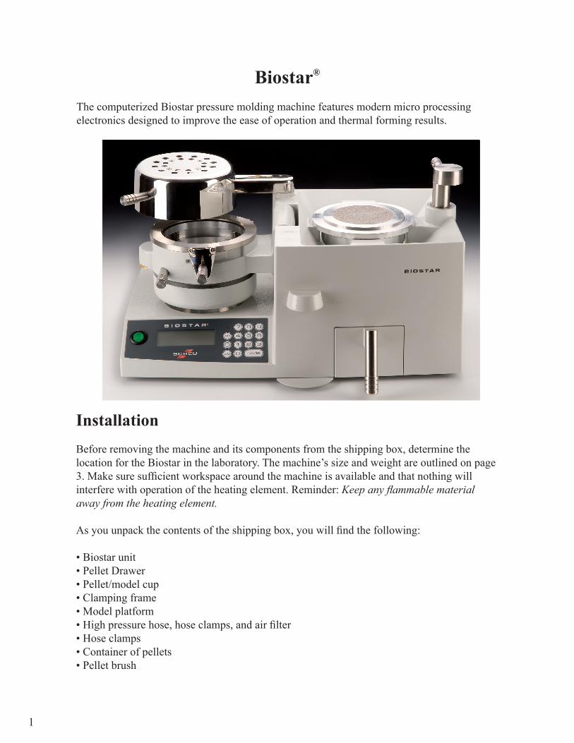
The computerized Biostar pressure molding machine features modern micro processingelectronics designed to improve the ease of operation and thermal forming results.
InstallationBefore removing the machine and its components from the shipping box, determine thelocation for the Biostar in the laboratory. The machine’s size and weight are outlined on page3. Make sure sufficient workspace around the machine is available and that nothing willinterfere with operation of the heating element. Reminder: Keep any flammable materialaway from the heating element.
As you unpack the contents of the shipping box, you will find the following:
• Biostar unit• Pellet Drawer• Pellet/model cup• Clamping frame• Model platform• High pressure hose, hose clamps, and air filter• Hose clamps• Container of pellets• Pellet brush
1
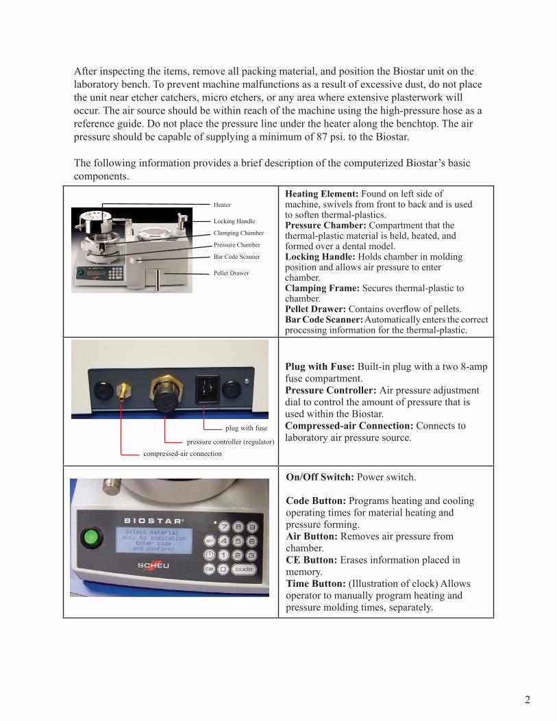
Heating Element: Found on left side ofmachine, swivels from front to back and is usedto soften thermal-plastics.Pressure Chamber: Compartment that thethermal-plastic material is held, heated, andformed over a dental model.Locking Handle: Holds chamber in moldingposition and allows air pressure to enterchamber.Clamping Frame: Secures thermal-plastic tochamber.Pellet Drawer: Contains overflow of pellets.Bar Code Scanner: Automatically enters the correct processing information for the thermal-plastic.
Plug with Fuse: Built-in plug with a two 8-ampfuse compartment.Pressure Controller: Air pressure adjustmentdial to control the amount of pressure that isused within the Biostar.Compressed-air Connection: Connects tolaboratory air pressure source.
On/Off Switch: Power switch.
Code Button: Programs heating and coolingoperating times for material heating andpressure forming.Air Button: Removes air pressure fromchamber.CE Button: Erases information placed inmemory.Time Button: (Illustration of clock) Allowsoperator to manually program heating andpressure molding times, separately.
After inspecting the items, remove all packing material, and position the Biostar unit on thelaboratory bench. To prevent machine malfunctions as a result of excessive dust, do not placethe unit near etcher catchers, micro etchers, or any area where extensive plasterwork willoccur. The air source should be within reach of the machine using the high-pressure hose as areference guide. Do not place the pressure line under the heater along the benchtop. The airpressure should be capable of supplying a minimum of 87 psi. to the Biostar.
The following information provides a brief description of the computerized Biostar’s basiccomponents.
2
plug with fuse
compressed-air connectionpressure controller (regulator)
Heater
Locking Handle
Clamping Chamber
Pressure Chamber
Bar Code Scanner
Pellet Drawer
3
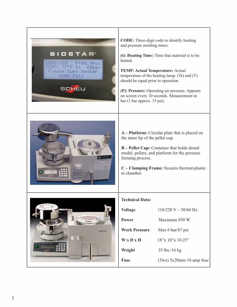
CODE: Three-digit code to identify heatingand pressure molding times.
(t): Heating Time: Time that material is to beheated.
TEMP: Actual Temperature: Actualtemperature of the heating lamp. (Ts) and (T)should be equal prior to operation.
(P): Pressure: Operating air pressure. Appearson screen every 10 seconds. Measurement inbar (1 bar approx. 15 psi).
A – Platform: Circular plate that is placed onthe inner lip of the pellet cup.
B – Pellet Cup: Container that holds dentalmodel, pellets, and platform for the pressureforming process.
C – Clamping Frame: Secures thermal-plasticto chamber.
Technical Data:
Voltage 110/220 V – 50/60 Hz
Power Maximum 850 W
Work Pressure Max 6 bar/87 psi
W x D x H 18”x 10”x 10.25”
Weight 35 lbs./16 kg
Fuse (Two) 5x20mm 10 amp fuse
A
BC
4
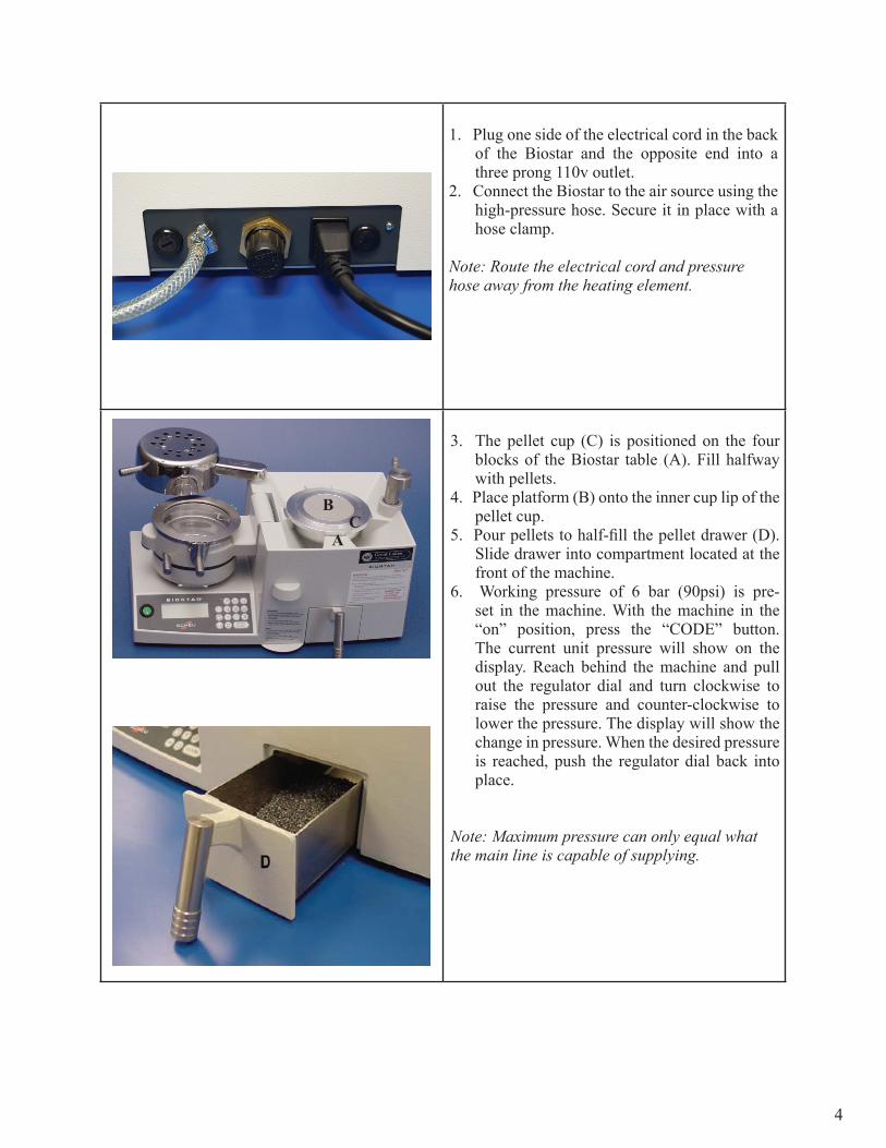
1. Plug one side of the electrical cord in the back of the Biostar and the opposite end into a three prong 110v outlet.
2. Connect the Biostar to the air source using the high-pressure hose. Secure it in place with a hose clamp.
Note: Route the electrical cord and pressurehose away from the heating element.
3. The pellet cup (C) is positioned on the four blocks of the Biostar table (A). Fill halfway with pellets.
4. Place platform (B) onto the inner cup lip of the pellet cup.
5. Pour pellets to half-fill the pellet drawer (D). Slide drawer into compartment located at the front of the machine.
6. Working pressure of 6 bar (90psi) is pre-set in the machine. With the machine in the “on” position, press the “CODE” button. The current unit pressure will show on the display. Reach behind the machine and pull out the regulator dial and turn clockwise to raise the pressure and counter-clockwise to lower the pressure. The display will show the change in pressure. When the desired pressure is reached, push the regulator dial back into place.
Note: Maximum pressure can only equal whatthe main line is capable of supplying.
A
BC
Reminder: Do not use material thicker than 5.0mm within the clamping mechanism. Thismay cause the Biostar to malfunction while pressure is in the chamber. Always wear safetyglasses when using this machine and during all fabrication procedures.
Maintenance
A regular maintenance schedule should be followed. Proper maintenance will assure betterfabrication results. Refrain from using water in the Biostar machine. Water may cause certaincomponents to rust or corrode. When the machine is not being used, engage the clampingframe to the chamber and position the chamber on the pellet cup. This prevents lab dust fromentering the pellet cup and chamber.
5
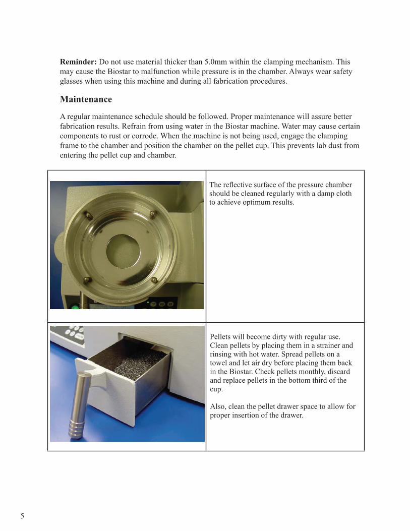
The reflective surface of the pressure chambershould be cleaned regularly with a damp clothto achieve optimum results.
Pellets will become dirty with regular use.Clean pellets by placing them in a strainer andrinsing with hot water. Spread pellets on atowel and let air dry before placing them backin the Biostar. Check pellets monthly, discardand replace pellets in the bottom third of thecup.
Also, clean the pellet drawer space to allow forproper insertion of the drawer.
6
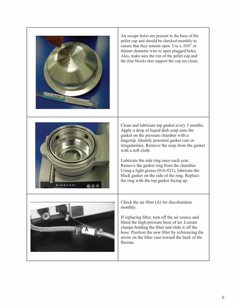
Air escape holes are present in the base of thepellet cup and should be checked monthly toensure that they remain open. Use a .036” orthinner diameter wire to open plugged holes.Also, make sure the rim of the pellet cup andthe four blocks that support the cup are clean.
Clean and lubricate top gasket every 3 months.Apply a drop of liquid dish soap onto thegasket on the pressure chamber with afingertip. Identify potential gasket cuts orirregularities. Remove the soap from the gasketwith a soft cloth.
Lubricate the side ring once each year.Remove the gasket ring from the chamber.Using a light grease (016-021), lubricate theblack gasket on the side of the ring. Replacethe ring with the top gasket facing up.
Check the air filter (A) for discolorationmonthly.
If replacing filter, turn off the air source andbleed the high-pressure hose of air. Loosenclamps holding the filter and slide it off thehose. Position the new filter by referencing thearrow on the filter case toward the back of theBiostar.

7
Place the pellet cup flush onto the four metalblocks on the Biostar table. Empty cup or reducethe pellet line to the half-way level. Make sure theinner lip of the cup is clean. Place the outer ring ofthe platform on the inner lip of the pellet cup withthe flat platform surface on top.
Operation
There are three basic functions to operate the Biostar including:
• Model preparation • Heating cycle • Pressure molding process
Preparation of Models
Prepare models for the thermal forming process by removing bubbles or filling voids whetherusing the platform or pellets. The platform is used when forming soft or thin plastics. Pelletsare used when forming thick, less flexible materials. The pellets prevent the plastic fromforming to unwanted areas of the dental cast. In either case, the model should be placed withthe incisors facing towards the locking handle.
Use of the Platform
The platform is used to expose the entire dental mold to the formation of the thermal-plastic.It eliminates having to use pellets. Pellets are difficult to remove from softer material (i.e.soft mouthguard material) and can create a higher occurrence of air leaks during the pressureforming process when using thinner thermal-plastics (i.e. < 1mm thick).
Use of the Pellets
A five-pound container of pellets is supplied with each Biostar. Pellets are used toprevent the thermal-plastic material from stretching over areas of the model that are not partof the appliance design. The pellets will flatten if compressed by the pressure chamberon the rim of the cup preventing machine damage. Stainless steel pellets are also availablebut can cause damage to the cup’s rim if compressed by the pressure chamber. Use ofmaterials other than the manufacturer’s recommended pellets may result in machinemalfunction and will void the warranty.
Work models are packed in pellets:
1. to support the model so that the occlusal-incisal plane is level with the rim of the cup.2. to prevent the material from forming on the facial surfaces of the teeth, making it hard to
remove the appliance from the work model.3. to prevent heated material from melting the wax used to support the wires on facial areas.
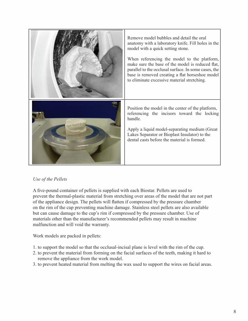
Remove model bubbles and detail the oralanatomy with a laboratory knife. Fill holes in themodel with a quick setting stone.
When referencing the model to the platform, make sure the base of the model is reduced flat, parallel to the occlusal surface. In some cases, the base is removed creating a flat horseshoe model to eliminate excessive material stretching.
Position the model in the center of the platform,referencing the incisors toward the locking handle.
Apply a liquid model-separating medium (GreatLakes Separator or Bioplast Insulator) to thedental casts before the material is formed.
8

Enough pellets must be placed in pellet cup tohold the model at proper level. Materialtermination areas, located on the facial surface ofthe model, should be referenced at the sameheight as the top ledge of the pellet cup.
Models attached to articulator mountings may bereferenced slightly higher than indicated.
Remove the pellet drawer and pour pelletsbetween the model and the inner wall of the cup.Apply more than enough pellets in these areas.Use a Biostar brush to remove excess pellets andlevel the pellet line from the occlusal-incisalplane to the top rim of the cup. Hold the brush atan angle to sweep excess pellets from the rim ofthe cup and the palatal area of the model.
Note: The pellet level should always be to the topof the cup. The height of the model in the pelletswill change with various applications.
9

For example, when constructing an orthodontic retainer, the pellets are placed against the occlusal-incisal margin to cover the wax holding the wires facially. The pellets act as an insulator when the heated material is formed.
Improper packing of a model (shown at left) can cause a blowout, air leak or machine malfunction. It is important that there is no sudden drop of the pellet margin at the inner cup wall or that the model is not positioned too high or low within the cup. This allows the material to be overstretched, thinning it to where a hole is created and air blows through.
In some instances, an air leak could cause inferior material adaptation that can result in a poorly fitted appliance.
Models mounted to articulator plates should be splitcast. If the model cannot be removed from the mounting, the pellet level will need to be at a slight incline; to appliance termination areas.
10
Material Heating Process
Select an appropriate disc of material specific to the appliance being fabricated. Place a disc of material on the gasket of the pressure chamber. Position the clamping frame over the material, so that the bayonet clamps slip under the bevel of the locking device on the sides of the chamber. Tighten by turning the handle clockwise (do not over tighten).
11
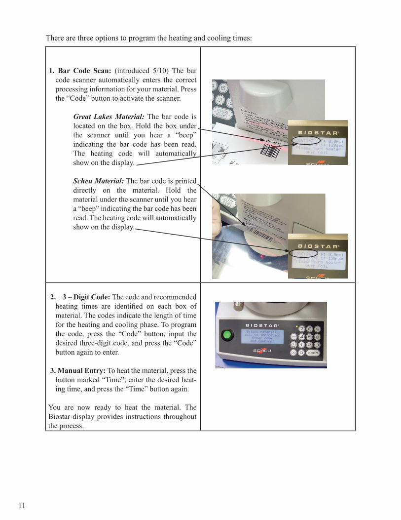
1. Bar Code Scan: (introduced 5/10) The bar code scanner automatically enters the correct processing information for your material. Press the “Code” button to activate the scanner.
Great Lakes Material: The bar code is located on the box. Hold the box under the scanner until you hear a “beep” indicating the bar code has been read. The heating code will automatically show on the display.
Scheu Material: The bar code is printed directly on the material. Hold the material under the scanner until you hear a “beep” indicating the bar code has been read. The heating code will automatically show on the display.
2. 3 – Digit Code: The code and recommended heating times are identified on each box of material. The codes indicate the length of time for the heating and cooling phase. To program the code, press the “Code” button, input the desired three-digit code, and press the “Code” button again to enter.
3. Manual Entry: To heat the material, press the button marked “Time”, enter the desired heat-ing time, and press the “Time” button again.
You are now ready to heat the material. The Biostar display provides instructions throughout the process.
There are three options to program the heating and cooling times:
12
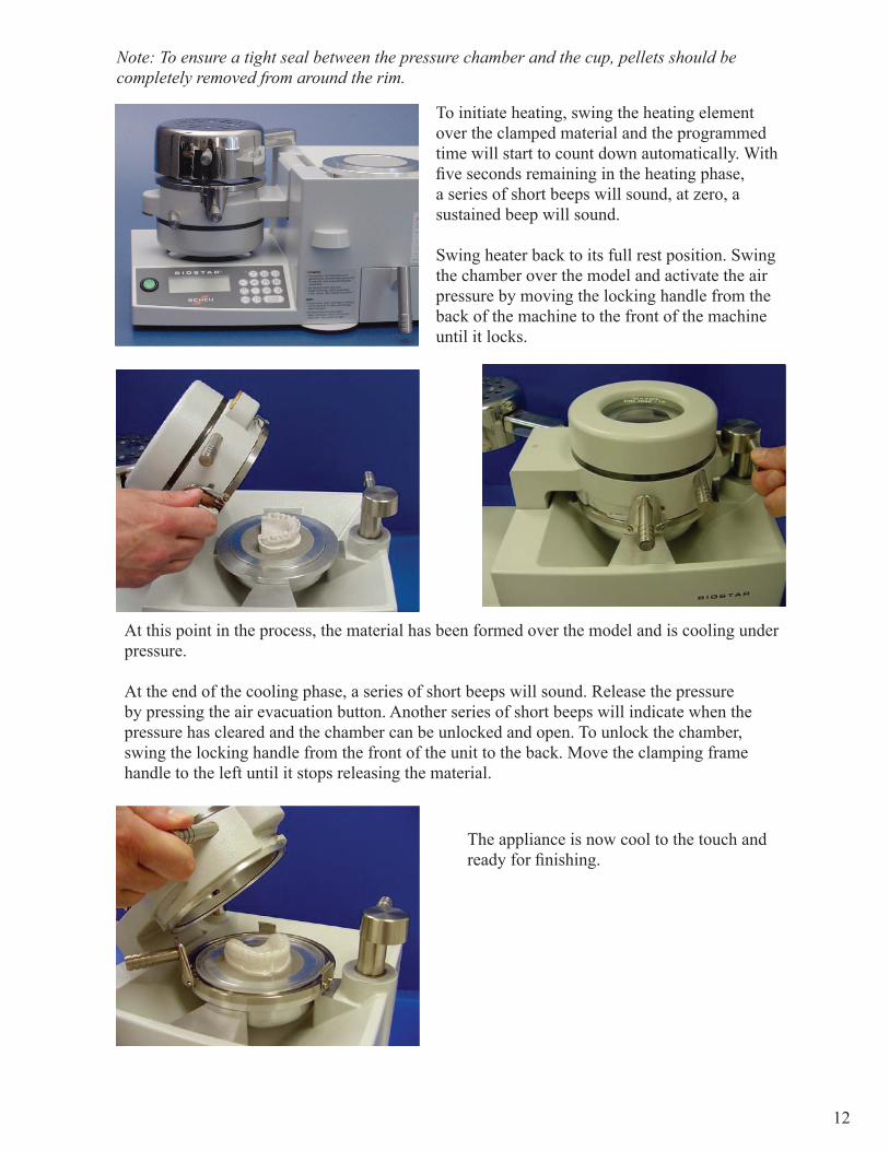
Note: To ensure a tight seal between the pressure chamber and the cup, pellets should be completely removed from around the rim.
To initiate heating, swing the heating element over the clamped material and the programmed time will start to count down automatically. With five seconds remaining in the heating phase, a series of short beeps will sound, at zero, a sustained beep will sound.
Swing heater back to its full rest position. Swing the chamber over the model and activate the air pressure by moving the locking handle from the back of the machine to the front of the machine until it locks.
At this point in the process, the material has been formed over the model and is cooling under pressure.
At the end of the cooling phase, a series of short beeps will sound. Release the pressure by pressing the air evacuation button. Another series of short beeps will indicate when the pressure has cleared and the chamber can be unlocked and open. To unlock the chamber, swing the locking handle from the front of the unit to the back. Move the clamping frame handle to the left until it stops releasing the material.
The appliance is now cool to the touch and ready for finishing.
13
Note: The BIOSTAR ispreset at 60lbs. or 4-5 barsof working pressure.
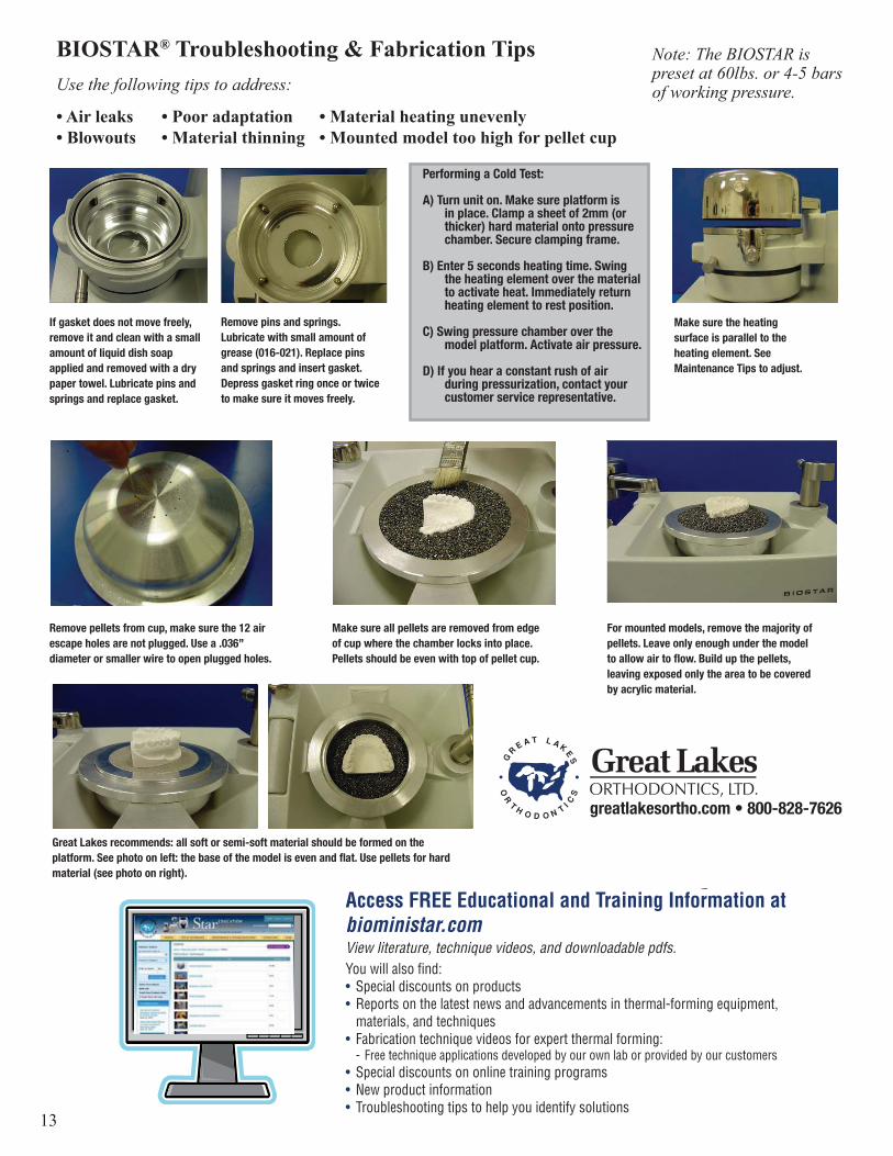
BIOSTAR® Troubleshooting & Fabrication TipsUse the following tips to address:
• Air leaks • Poor adaptation • Material heating unevenly• Blowouts • Material thinning • Mounted model too high for pellet cup
Ask for a Heating Times &
Applications Guide to help you get the
best results from your BIOSTAR.
1-800-828-7626greatlakesortho.com
Performing a Cold Test:
A) Turn unit on. Make sure platform is in place. Clamp a sheet of 2mm (or thicker) hard material onto pressure chamber. Secure clamping frame.
B) Enter 5 seconds heating time. Swing the heating element over the material to activate heat. Immediately return heating element to rest position.
C) Swing pressure chamber over the model platform. Activate air pressure.
D) If you hear a constant rush of air during pressurization, contact your customer service representative.
If gasket does not move freely,remove it and clean with a smallamount of liquid dish soapapplied and removed with a drypaper towel. Lubricate pins andsprings and replace gasket.
Remove pins and springs.Lubricate with small amount ofgrease (016-021). Replace pinsand springs and insert gasket.Depress gasket ring once or twiceto make sure it moves freely.
Make sure the heatingsurface is parallel to theheating element. SeeMaintenance Tips to adjust.
Remove pellets from cup, make sure the 12 airescape holes are not plugged. Use a .036”diameter or smaller wire to open plugged holes.
Make sure all pellets are removed from edgeof cup where the chamber locks into place.Pellets should be even with top of pellet cup.
For mounted models, remove the majority ofpellets. Leave only enough under the modelto allow air to flow. Build up the pellets,leaving exposed only the area to be coveredby acrylic material.
Great Lakes recommends: all soft or semi-soft material should be formed on theplatform. See photo on left: the base of the model is even and flat. Use pellets for hardmaterial (see photo on right).
13
Note: The BIOSTAR ispreset at 60lbs. or 4-5 barsof working pressure.
BIOSTAR® Troubleshooting & Fabrication TipsUse the following tips to address:
• Air leaks • Poor adaptation • Material heating unevenly• Blowouts • Material thinning • Mounted model too high for pellet cup
Ask for a Heating Times &
Applications Guide to help you get the
best results from your BIOSTAR.
1-800-828-7626greatlakesortho.com
Performing a Cold Test:
A) Turn unit on. Make sure platform is in place. Clamp a sheet of 2mm (or thicker) hard material onto pressure chamber. Secure clamping frame.
B) Enter 5 seconds heating time. Swing the heating element over the material to activate heat. Immediately return heating element to rest position.
C) Swing pressure chamber over the model platform. Activate air pressure.
D) If you hear a constant rush of air during pressurization, contact your customer service representative.
If gasket does not move freely,remove it and clean with a smallamount of liquid dish soapapplied and removed with a drypaper towel. Lubricate pins andsprings and replace gasket.
Remove pins and springs.Lubricate with small amount ofgrease (016-021). Replace pinsand springs and insert gasket.Depress gasket ring once or twiceto make sure it moves freely.
Make sure the heatingsurface is parallel to theheating element. SeeMaintenance Tips to adjust.
Remove pellets from cup, make sure the 12 airescape holes are not plugged. Use a .036”diameter or smaller wire to open plugged holes.
Make sure all pellets are removed from edgeof cup where the chamber locks into place.Pellets should be even with top of pellet cup.
For mounted models, remove the majority ofpellets. Leave only enough under the modelto allow air to flow. Build up the pellets,leaving exposed only the area to be coveredby acrylic material.
Great Lakes recommends: all soft or semi-soft material should be formed on theplatform. See photo on left: the base of the model is even and flat. Use pellets for hardmaterial (see photo on right).
Access FREE Educational and Training Information at bioministar.comView literature, technique videos, and downloadable pdfs. You will also fi nd:• Special discounts on products• Reports on the latest news and advancements in thermal-forming equipment,
materials, and techniques• Fabrication technique videos for expert thermal forming: - Free technique applications developed by our own lab or provided by our customers• Special discounts on online training programs• New product information• Troubleshooting tips to help you identify solutions
14
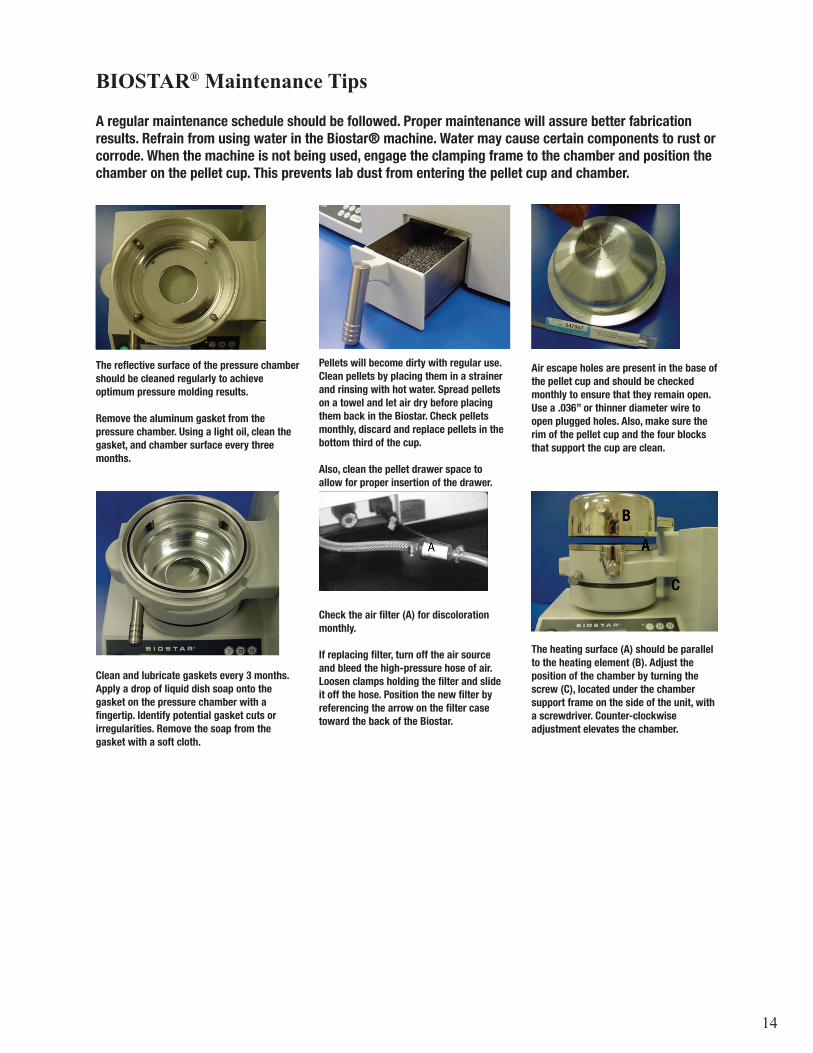
BIOSTAR® Maintenance Tips
A regular maintenance schedule should be followed. Proper maintenance will assure better fabricationresults. Refrain from using water in the Biostar® machine. Water may cause certain components to rust orcorrode. When the machine is not being used, engage the clamping frame to the chamber and position thechamber on the pellet cup. This prevents lab dust from entering the pellet cup and chamber.
The reflective surface of the pressure chambershould be cleaned regularly to achieveoptimum pressure molding results.
Remove the aluminum gasket from thepressure chamber. Using a light oil, clean thegasket, and chamber surface every threemonths.
Air escape holes are present in the base ofthe pellet cup and should be checkedmonthly to ensure that they remain open.Use a .036” or thinner diameter wire toopen plugged holes. Also, make sure therim of the pellet cup and the four blocksthat support the cup are clean.
Clean and lubricate gaskets every 3 months.Apply a drop of liquid dish soap onto thegasket on the pressure chamber with afingertip. Identify potential gasket cuts orirregularities. Remove the soap from thegasket with a soft cloth.
The heating surface (A) should be parallelto the heating element (B). Adjust theposition of the chamber by turning thescrew (C), located under the chambersupport frame on the side of the unit, witha screwdriver. Counter-clockwiseadjustment elevates the chamber.
Pellets will become dirty with regular use.Clean pellets by placing them in a strainerand rinsing with hot water. Spread pelletson a towel and let air dry before placingthem back in the Biostar. Check pelletsmonthly, discard and replace pellets in thebottom third of the cup.
Also, clean the pellet drawer space toallow for proper insertion of the drawer.
Check the air filter (A) for discolorationmonthly.
If replacing filter, turn off the air sourceand bleed the high-pressure hose of air.Loosen clamps holding the filter and slideit off the hose. Position the new filter byreferencing the arrow on the filter casetoward the back of the Biostar.

SMPI2Rev013117S-178
Exam
ple: Code # 244 =
220ºC/427ºF tem
perature
24 = 100 seconds
heating time
4 =
150 seconds cooling phase
Biostar
® C
odes
Chart 1
Heating Phase
Codes
220º C/427ºF
Standard10
1112
1314
1516
1718
1920
2122
2324
2526
2728
29
Heating Tim
eSeconds
2025
3035
4045
5055
6065
7075
8090
100110
120140
150160
Chart 2
Cooling Phase
Code
Time
(sec.)0
01
202
603
1204
1505
1806
2407
3008
3609
420


![[EN] 200820 Casestudy KNPC Kuwait · KNPC in house T&A systems Migration tool BioStar 2 API TCP/IP TCP/IP Wiegand Relay RS485 Input BioStar 2 BioStar 1 Server BioStar 1 FaceStation](https://static.fdocuments.net/doc/165x107/6067ab95910a7d53994515e1/en-200820-casestudy-knpc-kuwait-knpc-in-house-ta-systems-migration-tool-biostar.jpg)