BioScan BSR Series Operations Manual
68
© 2006 IDTi BioScan BSR Series Operations Manual Kolon Science Valley 1, #11FL. Guro Gu Guro Dong Seoul, 152-050, Korea Phone:+82-502-845-2959 Fax: +82-502-846-2950 URL: www.idti.co.kr HelpAndManual_unregistered_evaluation_copy
-
Upload
quijote1381 -
Category
Documents
-
view
153 -
download
1
Transcript of BioScan BSR Series Operations Manual

© 2006 IDTi
BioScan BSR Series Operations Manual
Kolon Science Valley 1, #11FL.Guro Gu Guro DongSeoul, 152-050, KoreaPhone:+82-502-845-2959Fax: +82-502-846-2950URL: www.idti.co.kr
HelpAndManual_unregistered_evaluation_copy
CopyrightBioScan BSR Series Operations Manual
Manual COPYRIGHT (C) 2004 IDT Inc. All rights reserved.
The Information in this document is subject to change without notice. IDT Inc.reserves the right to revise this document and to make changes from time to timein the content hereof without obligation to notify any person or persons of suchrevisions or changes. The software described in this document is supplied under alicense agreement and is protected by international copyright laws. You may copyit only for the purpose of backup and use it only as described in the Licenseagreement. Any implied warranties including any warranties of merchantability orfitness for a particular purpose are limited to the terms of the express warrantiesset out in the license agreement.
Program COPYRIGHT (C) 2003-2004 IDT Inc. All rights reserved.
Trademarks
BioScan is a registered trademark of IDT Inc.
BSR-121 is a registered trademark of IDT Inc.
Other products, trademarks or registered trademarks are the property of theirrespective owners.
HelpAndManual_unregistered_evaluation_copy

Limited Warranty
All Products sold to Dealer hereunder shall be subject to IDTi standard warrantyfor the Product included with the Product by IDTi (“Product Warranty”). TheProduct Warranty shall be extended to end user purchasers of the Products fromDealer who purchases such Products within twelve (12) months of the date theProducts are shipped to Dealer. Provided within the aforementioned time period,the warranty period for a Product shall commence upon the date stated in theProduct Warranty. Dealer shall not extend any warranty regarding the Productsother than IDTi then standard warranty. The limited warranty statement includedin the Product Warranty is the exclusive statement of the controlling terms andconditions of the limited warranties on the Products. Nothing in this Agreement orany other written document or any oral communications with Dealer or otherparties may alter the terms and conditions of the Product Warranty. IDTi may, inits sole discretion, revise its limited warranties from time to time, however; nochange in limited warranties will affect Product orders already accepted by IDTi.Dealer agrees to only pass on to Dealer’s end-users IDTi limited warranties andDealer will be liable for any greater warranty that Dealer purposely orinadvertently transfers to end-users. Dealer will indemnify, defend and hold IDTiharmless for any damages or other costs that arise because of Dealer’s failure toproperly inform Dealer’s end-users of current limited warranties.
Warranty Disclaimer: IDTi MAKES NO EXPRESS OR IMPLIED WARRANTIESFOR THE PRODUCTS EXCEPT THOSE INCLUDED IN THE PRODUCTWARRANTY. IDTi DISCLAIMS ALL OTHER WARRANTIES, EXPRESS ORIMPLIED, INCLUDING, WITHOUT LIMITATION, IMPLIED WARRANTIES OFMERCHANTABILITY AND FITNESS FOR A PARTICULAR PURPOSE.
HelpAndManual_unregistered_evaluation_copy

BioScan BSR Series Operations ManualI
© 2006 IDTi
Table of Contents
Foreword 0
Part I Overview 2
................................................................................................................................... 21 Overview
................................................................................................................................... 32 About BSR
................................................................................................................................... 43 Using the Fingeprint Scanner
Part II Quick Start 7
................................................................................................................................... 71 Pre-Installation Checklist
................................................................................................................................... 72 Entering the System Menu
.......................................................................................................................................................... 7If Administrator has been enrolled
.......................................................................................................................................................... 8If no Administrator has been enrolled
................................................................................................................................... 83 Operating BioScan
.......................................................................................................................................................... 8Operating with User PIN
.......................................................................................................................................................... 8Operating with User CARD
.......................................................................................................................................................... 9Operating with User FINGERPRINT
.......................................................................................................................................................... 9Operating in PIN & FINGERPRINT
.......................................................................................................................................................... 9Operating in CARD & FINGERPRINT
.......................................................................................................................................................... 10Operating in PIN & CARD
.......................................................................................................................................................... 10Operating in PIN & FINGERPRINT
................................................................................................................................... 104 Operating Funtion Key
.......................................................................................................................................................... 11Operating Function Key in PIN
.......................................................................................................................................................... 11Operating Function Key in CARD
.......................................................................................................................................................... 11Operating Function Key in FINGERPRINT
.......................................................................................................................................................... 12Operating Function Key in CARD and FINGERPRINT
.......................................................................................................................................................... 12Operating Function Key in PIN & FINGERPRINT
.......................................................................................................................................................... 12Operating Function Key in PIN and CARD
.......................................................................................................................................................... 13Operating Function Key in PIN & CARD & FINGERPRINT
Part III SYSTEM MENU 1 - ENROLL USER 15
................................................................................................................................... 151 1. Enroll Fingerprint User
................................................................................................................................... 162 2. Enroll Card User
................................................................................................................................... 173 3. Enroll Card & Fingerprint User
................................................................................................................................... 184 4. Enroll Block of Card User
................................................................................................................................... 195 5. Enroll Block of Card User 2
Part IV SYSTEM MENU 2 - EDIT USER 22
................................................................................................................................... 221 1. Edit User ID
................................................................................................................................... 222 2. Edit User Fingerprint
................................................................................................................................... 233 3. Edit User Card
................................................................................................................................... 234 4. Edit User Level
................................................................................................................................... 245 5. Edit User Name
IIContents
II
© 2006 IDTi
................................................................................................................................... 256 6. Option (ID)
Part V SYSTEM MENU 3 - VIEW USER 28
................................................................................................................................... 281 1. User List
................................................................................................................................... 292 2. Events
................................................................................................................................... 303 3. Firmware
................................................................................................................................... 304 4. Finger Version
Part VI SYSTEM MENU 4 - DELETE USER 33
................................................................................................................................... 331 1. Delete Single User
................................................................................................................................... 332 2. Delete All User
Part VII SYSTEM MENU 5 - SYSTEM SETUP 35
................................................................................................................................... 351 1. Time
................................................................................................................................... 352 2. Operating Mode
.......................................................................................................................................................... 37Setting Operating Mode
................................................................................................................................... 383 3. Address
................................................................................................................................... 394 4. Communication Password
................................................................................................................................... 395 5. Site Code
................................................................................................................................... 406 6. System Reset
................................................................................................................................... 417 7. Event Reset
................................................................................................................................... 428 8. Com. Speed
................................................................................................................................... 439 9. Date Format
................................................................................................................................... 4410 10. Custom Display
................................................................................................................................... 4611 11. LCD Light
................................................................................................................................... 4712 12. Conceal PIN
................................................................................................................................... 4813 13. Relay Board
................................................................................................................................... 4814 14. Attendance
Part VIII SYSTEM MENU 6 - SCANNER SETUP 50
................................................................................................................................... 501 Re-Scanning
................................................................................................................................... 502 Level
................................................................................................................................... 513 Lighting Condition
................................................................................................................................... 514 Enroll Mode
................................................................................................................................... 515 Identification Speed
Part IX USING THE BSR WITH BSC 54
................................................................................................................................... 541 BSC Connection
................................................................................................................................... 542 Synchronizing Database
Part X INSTALLATION GUIDE 56

BioScan BSR Series Operations ManualIII
© 2006 IDTi
................................................................................................................................... 561 Connector Layout
................................................................................................................................... 572 Power Connector
................................................................................................................................... 583 RRE Connector
................................................................................................................................... 594 RS232 Connector
................................................................................................................................... 605 RS422 Connector
Index 61

BioScan BSC Series Operations Manual
Part
I

BioScan BSR Series Operations Manual2
© 2006 IDTi
1 Overview
1.1 Overview
Cost effective: All-in-one solution that combines a biometric reader, proximity reader, and PINPADdevices for access control panels. BioScan lowers the cost per door for adding the convenience andsecurity of fingerprint verification technology to access control systems.
Advanced Sensor Technology: Its ability to recognize fingerprints in the face of adverse conditionslike dirt makes the BioScan useful for factories, plants, construction sites and similar environments thathave previously been unable to implement biometric-based access solutions.
FEATURES
§ Industry leading edge fingerprint algorithm (1st place in Fingerprint Verification Competition, FVC2004)
§ 1:1 Authentication and 1:Many Identification in less than 1 second§ Selectable dual or quad Fingerprint Enrollment for each user§ Multiple Security Modes: 11 total operating modes to choose from§ Custom user display name and custom standby display message § Integrated 32-character LCD display and 16 numeric keypad with luminescent backlight§ 20 programmable function keys§ Seamless Integration with BSC-101 and SmartScan Multi door control panels.§ Dual interface with Access Control and Time & Attendance software§ Free software and SDK for expanded functionality

Overview 3
© 2006 IDTi
SPECIFICATION
CONTROLLERUser Registration 4,096 Cards / 1,910 Templates / 9,000 TemplatesTransaction Buffer 16,000 TransactionsCommunications Standard: Wiegand / RS232Indicator 3 Colored Status LED with beeperPower Requirement 12V DC 1APhysical Dimensions: H130 * W147 * D51mm
Material: ABS (Polycarbonate)Environment Temperature: -0 ~50
Humidity: 10%~90%
FINGERPRINT SENSORCPU 400 MHz DSPFlash memory 1MB / 4 MBFAR 0.00008%FRR 0.09%Template size 256 ~ 384 Bytes (configurable, 384 Bytes default)Encryption 256 bit AESSize 55 x 40 x 8 mm (L x W x H)Sensor type OpticalResolution 500 (dpi)Sensing area 16.0 x 19.0 (mm)Image size 280 x 320 (pixel)
1.2 About BSR
BioScan BSR Series Operations Manual4
© 2006 IDTi
1.3 Using the Fingeprint Scanner
How Much Pressure is Required For a Good-Quality Fingerprint?
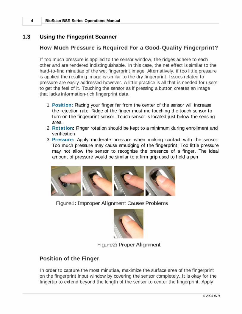
If too much pressure is applied to the sensor window, the ridges adhere to eachother and are rendered indistinguishable. In this case, the net effect is similar to thehard-to-find minutiae of the wet fingerprint image. Alternatively, if too little pressureis applied the resulting image is similar to the dry fingerprint. Issues related topressure are easily addressed however. A little practice is all that is needed for usersto get the feel of it. Touching the sensor as if pressing a button creates an imagethat lacks information-rich fingerprint data.
1. Posit ion: Placing your finger far from the center of the sensor will increasethe rejection rate. Ridge of the finger must me touching the touch sensor toturn on the fingerprint sensor. Touch sensor is located just below the sensingarea.
2. Rotation: Finger rotation should be kept to a minimum during enrollment andverification
3. Pressure: Apply moderate pressure when making contact with the sensor.Too much pressure may cause smudging of the fingerprint. Too little pressuremay not allow the sensor to recognize the presence of a finger. The idealamount of pressure would be similar to a firm grip used to hold a pen
Position of the Finger
In order to capture the most minutiae, maximize the surface area of the fingerprinton the fingerprint input window by covering the sensor completely. It is okay for thefingertip to extend beyond the length of the sensor to center the fingerprint. Apply

Overview 5
© 2006 IDTi
pressure lightly and evenly without moving it during the capturing process. Figure2shows the correct positioning of the fingerprint on the input window. Figure1 showsthe most common mistakes made during the initial phase of enrollment.
When the Red light (Fingerprint Scanner) is on, slide the finger across the scanner.1. Position the finger where the first joint of the finger meets the edge of the
sensor.2. Lower the finger onto the sensor and apply moderate pressure. 3. Keep the finger on the sensor until the Red light (fingerprint scanner) turns
off. You may then remove the finger
Getting Good Fingerprint Images
The quality of a fingerprint image is relative to the number of minutiae pointscaptured. If the number and locations of the minutiae remain consistent wheneveran individual's fingerprint image is scanned and captured, the fingerprint image issuccessfully matched to the template of the registered finger. Fingerprint imagesthat do not contain adequate minutiae data are not acceptable as personalcredentials, and are therefore invalid. Figure 3 shows poor-quality fingerprints,characterized by smudged, faded, or otherwise distorted areas on the fingerprint.Conditions like these may be attributable to a number of factors, includingexcessively dry or wet skin, or scarring.
1. Use index, middle or ring fingers2. Avoid using thumb and pinky fingers since they are typically awkward to
consistently position on the sensor3. Completely covering the area of the sensor with the fingerprint will provide the
best performance

BioScan BSC Series Operations Manual
Part
II
Quick Start 7
© 2006 IDTi
2 Quick Start
2.1 Pre-Installation Checklist
· Make sure all wires are checked.· check for communication module. There are several types of communications,
make sure you have the right modules.· If you're using converter, make sure TX and RX is crossed over between the
device and converter.· Set network address. All devices are defaulted to address 1. If you're connecting 2
or more, change network address to 2 and up.· Set site code also known as facility code if you're using cards.
2.2 Entering the System Menu
When the reader is powered on with no fingerprint templates enrolled in the unit,anyone can enter the system menu by pressing the F1/p key. If you are enrolling thefirst administrator template via the reader's keypad, you must first determine the1~16 digit PIN that the administrator will use. Once this PIN is determined, theadministrator must be present to enroll their fingerprint into the reader. Note thatthis operation is not valid if there are administrator templates in the reader.
BioScan factory default has no system administrator password. If you've just purchased the unit, youshould be able to get into the system mode by pressing the F1 key. Go to Enroll Fingerprint User toenroll template.
2.2.1 If Administrator has been enrolled
1Press F1/P key to enter system mode.
4Finger scanning message will appear
2Key in administrator ID followed by the # key
5Now you're into system mode. Press F1 key to scroll up the main menuPress F2 key to scroll down the main menu

BioScan BSR Series Operations Manual8
© 2006 IDTi
3Present either finger or card which ever administratorhas been enrolled with. For now we will use thefingerprint
2.2.2 If no Administrator has been enrolled
1Press F1/P key to enter system mode
2Now you're into system mode. Press F1 key to scroll up the main menuPress F2 key to scroll down the main menu
2.3 Operating BioScan
To use the BioScan, simply enter enrolled user fingerprint to the scanner. Touch sensor willautomatically activate the fingerprint sensor when user finger is presented to the scanner. Remove thefinger when red scanning light turns off.
There are 11 operating modes in the BioScan, depending on which mode is running, operatingBioScan varies.
2.3.1 Operating with User PIN
1From the standby menu, key in user PIN andpress the # key.
2Welcome message will appear if theverification has been successful.
2.3.2 Operating with User CARD
1From the standby menu, present user card tothe reader.
2Welcome message will appear if theverification has been successful.

Quick Start 9
© 2006 IDTi
2.3.3 Operating with User FINGERPRINT
1From the standby menu, present userfingerprint to the scanner. If the scannerdoesn't turn on then press the # key tomanually turn scanner on.
2Welcome message will appear if theverification has been successful.
2.3.4 Operating in PIN & FINGERPRINT
1 From thestandby menu, key in user PIN and press the# key.
3 Enter userfingerprint to the scanner.
2 Once theuser ID has been entered, fingerprintscanner will flash red.
4 Welcomemessage will appear if the verification hasbeen successful.
2.3.5 Operating in CARD & FINGERPRINT
1 From thestandby menu, present user card to thereader. Fingerprint scanner will flash red.
3 Welcomemessage will appear if the verification hasbeen successful.
2 Enter userfingerprint to the scanner.
BioScan BSR Series Operations Manual10
© 2006 IDTi
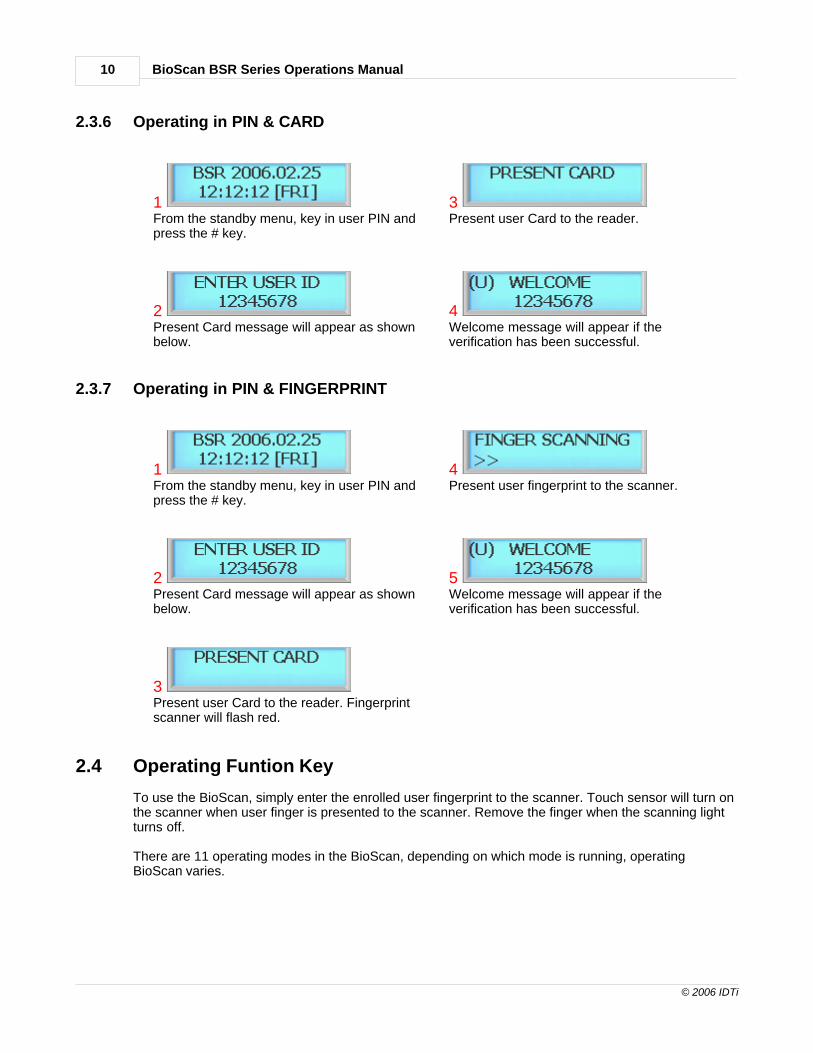
2.3.6 Operating in PIN & CARD
1From the standby menu, key in user PIN andpress the # key.
3Present user Card to the reader.
2Present Card message will appear as shownbelow.
4Welcome message will appear if theverification has been successful.
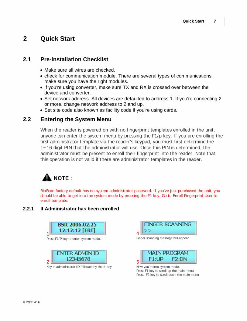
2.3.7 Operating in PIN & FINGERPRINT
1From the standby menu, key in user PIN andpress the # key.
4Present user fingerprint to the scanner.
2Present Card message will appear as shownbelow.
5Welcome message will appear if theverification has been successful.
3Present user Card to the reader. Fingerprintscanner will flash red.
2.4 Operating Funtion Key
To use the BioScan, simply enter the enrolled user fingerprint to the scanner. Touch sensor will turn onthe scanner when user finger is presented to the scanner. Remove the finger when the scanning lightturns off.
There are 11 operating modes in the BioScan, depending on which mode is running, operatingBioScan varies.

Quick Start 11
© 2006 IDTi
2.4.1 Operating Function Key in PIN
1From the standby menu, key in user PIN. DONOT PRESS THE # KEY.
3Key in user PIN but do not press the # key.
2Press function key "F2" followed by 1
4Welcome message with function key willappear if the verification has beensuccessful.
2.4.2 Operating Function Key in CARD
1From the standby menu, present user card tothe reader.
3Welcome message with function key willappear if the verification has beensuccessful.
2Press function key "F2" followed by 1
2.4.3 Operating Function Key in FINGERPRINT
1From the standby menu, present userfingerprint to the scanner. If the scannerdoesn't turn on then press the # keymanually turn on the scanner.
3Welcome message with function key willappear if the verification has beensuccessful.
2Press function key "F2" followed by 1

BioScan BSR Series Operations Manual12
© 2006 IDTi
2.4.4 Operating Function Key in CARD and FINGERPRINT
1From the standby menu, key in function key.
3Present user fingerprint to the scanner.
2Press function key "F2" followed by 1
4Welcome message with function key willappear if the verification has beensuccessful.
2.4.5 Operating Function Key in PIN & FINGERPRINT
1From the standby menu, key in user PIN. DONOT PRESS THE # KEY.
4Present user fingerprint to the scanner.
2Key in user PIN but do not press the # key.
5Welcome message with function key willappear if the verification has beensuccessful.
3Press function key "F2" followed by 1
2.4.6 Operating Function Key in PIN and CARD
1From the standby menu, key in user PIN. DONOT PRESS THE # KEY.
4Present user Card to the reader.

Quick Start 13
© 2006 IDTi
2Key in user PIN but do not press the # key.
5Welcome message with function key willappear if the verification has beensuccessful.
3Press function key "F2" followed by 1
2.4.7 Operating Function Key in PIN & CARD & FINGERPRINT
1From the standby menu, key in user PIN. DONOT PRESS THE # KEY.
4Present user Card to the reader. Fingerprintscanner will flash red
2Key in user PIN but do not press the # key.
5Present user fingerprint to the scanner.
3Press function key "F2" followed by 1
6Welcome message will appear if theverification has been successful.

BioScan BSC Series Operations Manual
Part
III

SYSTEM MENU 1 - ENROLL USER 15
© 2006 IDTi
3 SYSTEM MENU 1 - ENROLL USER
3.1 1. Enroll Fingerprint User
This command is used to add typical fingerprint only users to the reader so that theywill be able to gain entry to the location guarded by the reader. Up to 955 users or1,910 total fingerprint templates can be saved in the fingerprint reader, includingadministrative fingerprint templates, depending on the model of reader you have.The total number of user depends on how many templates has been applied to eachuser. The following key sequence performs this action:
1Press the # key to add users Fingerprint Template
5BioScan has an option to enroll 2 fingerprint templatesand 4 fingerprint templates per each user. For now wewill select number 2 key by enrolling 4 templates
2Select user level by pressing 1 through 4. Refer to NOTEabout user levels
6Present first finger to the scanner. Remove thefingerprint when the red light turns off. You can eitherenroll same fingerprint or different fingerprint after thefirst. Repeat this process until the last fingerprint
3Key in user ID from 1 to 16 digits as shown in nextfigure
7Scanning the last fingerprint.....
4Key in user ID followed by the # key
8Enroll completed. Press the # key to continue enrollinganother user fingerprint or press any others to exit offthe sub-menu
When the Red light (Fingerprint Scanner) is on, slide the finger across the scanner.1. Position the finger where the first joint of the finger meets the edge of the
sensor.2. Lower the finger onto the sensor and apply moderate pressure. 3. Keep the finger on the sensor until the Red light (fingerprint scanner) turns

BioScan BSR Series Operations Manual16
© 2006 IDTi
off. You may then remove the finger.
· Use thumb, index, middle or ring fingers.
· Avoid using pinky fingers since its typically awkward to consistently position onthe sensor.
· Completely covering the area of the sensor will provide the best performance.
There are four levels of administration,
1:USER (Level 1) - Corresponds to an ordinary user. They may verify, but are not allowed to accessany administrative functions. 2: RA (Level 2) - Corresponds to an enroller. These templates are allowed to add users to thesystem and verify existing users. However, they can only add users with no administrative privileges(Level 1) and can not access any other administrative functions. 3. AA (Level 3) - Corresponds to an administrator enroller. These templates are allowed to add upto (Level 3) administrator but not system administrator.4. SA (Level 4) - This is an system administrator level and has full rights to configure the reader.
3.2 2. Enroll Card User
This command is used to add typical card only users to the reader so that they willbe able to gain entry to the location guarded by the reader. Total number of usersare 4,096 based on card users only. If there are 500 fingerprint users enrolled in thesystem then 3,596 will be the remaining card user slots available in the system.Fingerprint user will be automatically assigned a card slot in the system memoryeven if they do not use or enrolled any card. The enrollment procedure is identical toadding fingerprint. The following key sequence performs this action:
1Press the # key to add user card
4Key in user ID followed by the # key
2Select user level by pressing 1 through 4
5Present user card to the reader or key in card numbermanually followed by the # key
SYSTEM MENU 1 - ENROLL USER 17
© 2006 IDTi
3Key in user ID from 1 to 16 digits as shown in nextfigure
6Enroll completed. Press # key to continue adding cardor press any other key to exit off the sub-menu
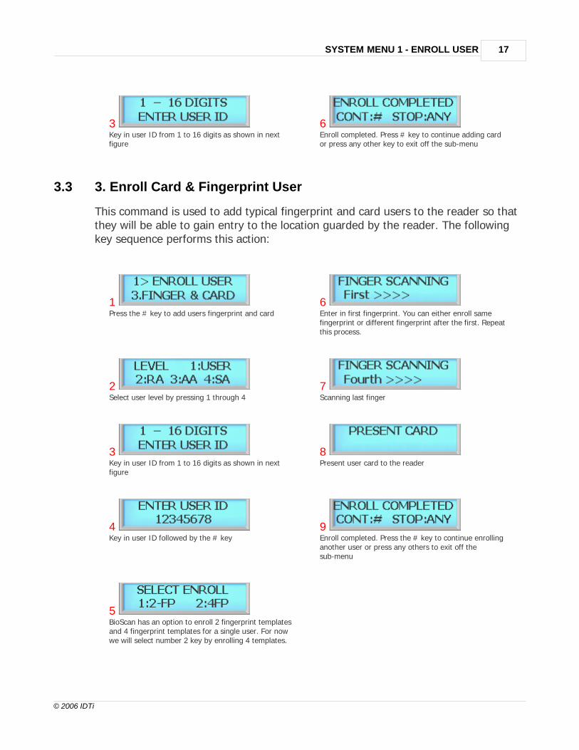
3.3 3. Enroll Card & Fingerprint User
This command is used to add typical fingerprint and card users to the reader so thatthey will be able to gain entry to the location guarded by the reader. The followingkey sequence performs this action:
1Press the # key to add users fingerprint and card
6Enter in first fingerprint. You can either enroll samefingerprint or different fingerprint after the first. Repeatthis process.
2Select user level by pressing 1 through 4
7Scanning last finger
3Key in user ID from 1 to 16 digits as shown in nextfigure
8Present user card to the reader
4Key in user ID followed by the # key
9Enroll completed. Press the # key to continue enrollinganother user or press any others to exit off thesub-menu
5BioScan has an option to enroll 2 fingerprint templatesand 4 fingerprint templates for a single user. For nowwe will select number 2 key by enrolling 4 templates.

BioScan BSR Series Operations Manual18
© 2006 IDTi
3.4 4. Enroll Block of Card User
This command is used to Enrolling a range of cards, Block enrollment by cardnumber range is best used when there is a large quantity of sequential ID numberedcards or credentials. Cards or credentials do not have to be on hand when enrolledthrough the block enrollment by card number range process, but you must have thefacility code. Below is an example to enroll 100 Users with card number starting with1000. User ID 1000 will be addressed card number 1000, User ID 1001 will beaddressed card number 1001 and so on. Card must be in sequential order to use theCard Block. Please check with your card provider for more information.
1Press the # key to add block of card user.
6Following message will appear. Enter in the totalnumber of cards to be enrolled as shown below
2Enter in first number of the block ID. This will be thefirst ID number of the card as shown in the next figure
7100 would be the total number of cards to be enrolled
31000 would be the first number of user ID
8Enrolling user card block. Please wait unit the processfinishes. This might take up to 5 minutes depending onthe total number of card block size.
4Following message will appear. Enter in the first cardnumber as shown below
9Enroll completed. Press the # key to continue addinganother or press any others to exit off the sub-menu
51000 would be the first number the card
This option will write block of cards in empty slot of the memory and will not delete currently enrolleduser. Card Block 1 will take more time than card block2 since it will search for empty slots in memory

SYSTEM MENU 1 - ENROLL USER 19
© 2006 IDTi
to enroll. Consider using card block2 if the memory is empty or stored memory is no longer needed.
3.5 5. Enroll Block of Card User 2
This command is used to Enrolling a range of cards, Block enrollment by cardnumber range is best used when there is a large quantity of sequential ID numberedcards or credentials. Cards or credentials do not have to be on hand when enrolledthrough the block enrollment by card number range process, but you must have thefacility code. Below is an example to enroll 100 Users with card number starting with1000. User ID 1000 will be addressed card number 1000, User ID 1001 will beaddressed card number 1001 and so on.
1Press the # key to add block of card user.
6 Following
message will appear. Enter in the total number of cardsto be enrolled as shown below
2Enter in first number of the block ID. This will be thefirst ID number of the card as shown in the next figure
7100 would be the total number of cards to be enrolled
31000 would be the first number of user ID
8Enrolling user card block. Please wait unit the processfinishes. This might take up to 5 minutes depending onthe total number of card block size.
4Following message will appear. Enter in the first cardnumber as shown below
9Enroll completed. Press the # key to continue addinganother or press any others to exit off the sub-menu
5 1000 would
be the first number the card
This option will write block of cards in empty slot of the memory and will not delete currently enrolled

BioScan BSR Series Operations Manual20
© 2006 IDTi
user. Card Block 1 will take more time than card block2 since it will search for empty slots in memoryto enroll. Consider using card block2 if the memory is empty or stored memory is no longer needed.

BioScan BSC Series Operations Manual
Part
IV

BioScan BSR Series Operations Manual22
© 2006 IDTi
4 SYSTEM MENU 2 - EDIT USER
4.1 1. Edit User ID
This command is used to edit existing users ID by accessing the user ID. Whenediting, Administrators have the ability to make changes to user ID only in thismenu.
1Press the # key to enter edit User ID
3Key in new user ID followed by the # key
2Key in user ID to be edited followed by the # key
4Edit completed. Press the # key to continue editinganother or press any others to exit off the sub-menu
4.2 2. Edit User Fingerprint
This command is used to edit existing users Fingerprint by accessing the user ID.When editing, Administrators have the ability to make changes to user Fingerprintonly in this menu.
1Press the # key enter user FINGER
4Enter in the first fingerprint. You can either add samefingerprint or different fingerprint after the first. Repeatthis process until the fourth fingerprint.
2Key in user ID to be edited followed by the # key
5Scanning the last finger....

SYSTEM MENU 2 - EDIT USER 23
© 2006 IDTi
3Press 1 to add 2 templatesPress 2 to add 4 templates
6Edit completed. Press the # key to continue editinganother or press any others to exit off the sub-menu
4.3 3. Edit User Card
This command is used to edit existing users Card by accessing the user ID. Whenediting, Administrators have the ability to make changes to user Card only in thismenu.
1Press the # key to enter edit user CARD
3Present new card to be enrolled or enter in the cardnumber manually followed by the # key. Make sure thecard has not been already enrolled in the BioScan
2Key in user ID to be edited followed by the # key
4Edit completed. Press the # key to continue editinganother or press any others to exit off the sub-menu
4.4 4. Edit User Level
This command is used to edit existing users level by accessing the user ID. Userlevels determine where a user will be valid. To edit an existing user edit user level,follow the steps below.
1Press the # key to enter edit user LEVEL
3(U) is the current user level. Select the user leve from1~4l to apply new level
2Key in user ID to be edited followed by the # key
4Edit completed. Press the # key to continue editinganother or press any others to exit off the sub-menu

BioScan BSR Series Operations Manual24
© 2006 IDTi
There are four levels of administration,
1:USER (Level 1) - Corresponds to an ordinary user. They may verify, but are not allowed to accessany administrative functions. 2: RA (Level 2) - Corresponds to an enroller. These templates are allowed to add users to thesystem and verify existing users. However, they can only add users with no administrative privileges(Level 1) and can not access any other administrative functions. 3. AA (Level 3) - Corresponds to an administrator enroller. These templates are allowed to add upto (Level 3) administrator but not system administrator.4. SA (Level 4) - This is an system administrator level and has full rights to configure the reader.
4.5 5. Edit User Name
BioScan is able to display custom user name instead of user ID when accessed.When the BioScan is expecting a name then the number keys on the keypad becomeletter keys: the letters below the keys apply. Press once to show the first uppercaseletter above the key; press four times to show the lowercase letter. When thedesired letter appears on the display, press the up-arrow(F1) to move on to the nextletter in the name.
1Press the # key to enter NAME
6Press the # key to continue editing the display option.Display option must be configured in order for it willwork properly
2Key in user ID to be edited followed by the # key
7Once again, enter in same ID you have just editedpreviously
3Press 1 key to enter user name
8This time select #2 to enter display option

SYSTEM MENU 2 - EDIT USER 25
© 2006 IDTi
4Key in text as shown in next figure. Continue onpressing the key to rotate from uppercase letters tolowercase letters. i.e. to display lowercase "c" press thenumber 2 key 6 times. Use the F1 key as space
9Select #2 to display ID by name. This will allow BioScanto display custom ID name instead of user ID
5Key in appropriate display name and then press the #key
10Edit completed. Press the # key to continue editinganother or press any others to exit off the sub-menu
NUMBER OF TIMES KEY IS PRESSEDKEYS 1 2 3 4 5 6 7 8
12 A B C a b c3 D E F d e f4 G H I g h i5 J K L j k l6 M N O m n o7 P Q R S p q r s8 T U V t u v9 W X Y Z w x y z0* Clear# Enter
F1 SpaceF2F3 Back SpaceF4 Escape
4.6 6. Option (ID)
ID Option is a special mode where user can access the unit with ID only. Whenapplied, user can override the current operating mode and access unit it with just anID (PIN). This option can be applied to those users who does not have card. Toapply this mode to user, follow the steps bellow.

BioScan BSR Series Operations Manual26
© 2006 IDTi
1Press the # key to enter OPTION (ID)
3Press 1 key to enable ID option to this userPress 2 key to disable ID option to this user
2Enter user ID to apply ID option followed by the # key
4Edit completed. Press the # key to continue editinganother or press any others to exit off the sub-menu

BioScan BSC Series Operations Manual
Part
V

BioScan BSR Series Operations Manual28
© 2006 IDTi
5 SYSTEM MENU 3 - VIEW USER
5.1 1. User List
At any time, you can view a list of all users of the system. The list can be an overallenrollment list of all users in the system, or it can be a list of the individual users thatare physically enrolled on any individual fingerprint reader. Total number of users are4,096 based on card users. The total number of fingerprint user depends on howmany templates has been applied to each user.
1Press the # key to enter to view USER LIST
3Press F3 key to view detail view of user
2Press F1/P key to scroll up the user list Press F2 key to scroll down the user list
4View Exit. Press the # key to continue viewing anotheror press any others to exit off the sub-menu

SYSTEM MENU 3 - VIEW USER 29
© 2006 IDTi
Viewing System User List The System User List will display the following information: . The user's PIN (Template ID) . The user's name . The user's administrator status . The user's template location in memory
5.2 2. Events
At any time, you can view all transaction of event logs of the system. A recordcreated that contains pertinent information about an occurrence in the access controland monitoring system.
1Press the # key to enter view EVENT
3Following event log will appear. Press F3 key to viewevent data
2Press F1 to scroll up the event log Press F2 key to scroll down the event log
4View Exit. Press the # key to continue viewing anotherevent or press any others to exit off the sub-menu

BioScan BSR Series Operations Manual30
© 2006 IDTi
Viewing System Event Log The System Event Log List will display the following information: . The date of event occurrence. The time of event occurrence . The total number of event log
5.3 3. Firmware
This is to view the current firmware version installed in BioScan. Other ways to verifythe firmware is to resetting the device. When first booting up, firmware version willdisplay.
1Press the # key to enter FIRMWARE VERSION
3Press # key to view firmware againPress any other key to exit
2Current firmware version number will display
5.4 4. Finger Version
This is to view the current fingerprint scanner version installed in BioScan.

SYSTEM MENU 3 - VIEW USER 31
© 2006 IDTi
1Press the # key to enter FINGER VERSION
3Press # key to view scanner version againPress any other key to exit
2Current fingerprint module version number will display.Latest version is V1.5C

BioScan BSC Series Operations Manual
Part
VI

SYSTEM MENU 4 - DELETE USER 33
© 2006 IDTi
6 SYSTEM MENU 4 - DELETE USER
6.1 1. Delete Single User
Deleting a fingerprint template from a reader will prevent that template from beinggranted access to the location via the reader. Any fingerprint template can beremoved from a fingerprint reader, including administrative and the last remainingfingerprint template on the reader. Templates can be deleted by a single user or allusers including administrative templates.
1Press the # key to enter delete Single User
3Enter in user ID from 1 to 16 digits
2Enter in user ID to be deleted as shown below
4Delete completed.
6.2 2. Delete All User
Deleting a fingerprint template from a reader will prevent that template from beinggranted access to the location via the reader. Any fingerprint template can beremoved from a fingerprint reader, including administrative and the last remainingfingerprint template on the reader. Templates can be deleted by a single user or allusers including administrative templates.
1Press the # key to enter delete All User
3Deleting. Please wait....
2Press the # key to confirm delete allPress any other key to cancel
4Delete completed.

BioScan BSC Series Operations Manual
Part
VII

SYSTEM MENU 5 - SYSTEM SETUP 35
© 2006 IDTi
7 SYSTEM MENU 5 - SYSTEM SETUP
7.1 1. Time
BioScan features an internal clock that provides the date and time for all loggedevents. This section discusses how to set the date and time that BioScan uses forevent logging. To set the current time, access the menu system and follow thesesteps:
1Press the # key to enter system Time
4Select day of the week. Press 1 through 7 to enter dayof the week. Refer to NOTE
2Enter current date
5Press the # key to confirm
3Enter current time in military time format. i.e. 20:20:20
6Set up has completed
7.2 2. Operating Mode
BioScan has 11 total operating mode. List is the detail view of the operating modesavailable in BioScan.

BioScan BSR Series Operations Manual36
© 2006 IDTi
1[CD / FP] - CARD or FINGERPRINT User can access the device by either card orfingerprint. When operating in this mode,simply enter user card or fingerprint to thedevice.
7[CD&FP] - Card & FingerprintUser must enter using user card &Fingerprint to access the unit. To operate inthis mode, enter user card followed by userfingerprint.
2[ID&FP/CD] - PIN & FINGERPRINT orCARDIn this mode, user can access the device byPIN with fingerprint or just a card. Tooperate in this mode, user must enter PINfirst before entering finger or present usercard.
8[ID&FP OR ID&CD] - PIN & Fingerprintor PIN & CardIn this mode user can access the device byentering user PIN and fingerprint or user PINand card. This mode is useful whennetworked with a proximity readers.
3[ID&CD&FP] - PIN & CARD &FINGERPRINTUser must use all three tokens to gainaccess. This is the highest security modeavailable in BioScan. To operate in thismode, first enter user PIN and press the #key, then present user card followed by userfingerprint.
9[ID&FP OR CARD&FP] - PIN &Fingerprint or Card & FingerprintIn this mode user can access the device byusing PIN with fingerprint or card withfingerprint.
4[ID/CD/FP] - PIN or CARD orFINGERPRINT (ANY MODE)User can access the device by any of theavailable tokens. This is the most convenientbut lowest security mode in BioScan. Tooperate in this mode, simply use any one ofthe token.
10[OPEN] - ALWAYS OPENAccess point will stay open for an emergencysuch as fire.

SYSTEM MENU 5 - SYSTEM SETUP 37
© 2006 IDTi
5[ F P OR ID / FP] - FINGER ONLY or ID& FINGERFingerprint reader will be the only accessibledevice and user must enter using fingerprint.All other token will be disabled. This is an1:1 or 1:N verification. User also have anoption to again access by entering user PINand entering user fingerprint for faster. Tooperate in this mode, enter user fingerprintor user PIN and Fingerprint
11[CLOSE] - ALWAYS CLOSEAccess point will stay locked for anemergency such as intrusion.
6[ID&FP] - PIN & FingerprintUser must enter using user PIN & Fingerprintto access the unit. To operate in this mode,enter user PIN and press the # key followedby user fingerprint.
12[TESTING MODE] - TESTING MODEIt will be a good idea to test the unit in thismode when first installed.
&: means "AND"
/: means "OR"
( ): means "OR"
7.2.1 Setting Operating Mode
This section provides information about how to choose the operation mode. ID/CD/FP (ALL) is the default operating mode.
1Press the # key to add users fingerprint template
3Press the # key to select operating mode. Refer to notefor available operating mode.

BioScan BSR Series Operations Manual38
© 2006 IDTi
2Press F1 key to scroll up the mode menu Press F2 key to scroll down the mode menu
4Setup completed
7.3 3. Address
Communication options allow BioScan to communicate with a PC and other doorcontrol equipment. In network applications, BioScan units communicate with aconnected PC. This requires each unit to have a unique identification code. To assigna Network ID, follow the steps listed below: Repeat this procedure for eachnetworked unit, assigning a unique identification code to each unit. Default addressis set to 1.

SYSTEM MENU 5 - SYSTEM SETUP 39
© 2006 IDTi
1Press the # key to enter Address
3Setup has completed
2Key in from 1 ~ 14 followed by the # key. You can assign network ID from 1 through 14. C standsfor current setting, sample shows address 1. Defaultaddress is set to address 1.
7.4 4. Communication Password
Communication password is used during network communication. This safeguardsthe information sent during transmission and also from hacking the system.
1Press the # key to enter Communication Password
3Key in the 8 digit password and press the # key toconfirm new password
2Current password is displayed. Enter new password asshow in next figure
4Setup has completed
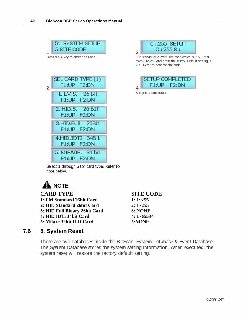
7.5 5. Site Code
A site code, which is sometimes called a facility code, differentiates one users cardgroup from another. A facility code is an integral code that is programmed into thecard at the time of manufacture. The additional code ensures that even if cardnumbers are duplicated by the manufacturer, that the cards will not operate onsomeone else's building who has a different facility code. Limitations inherent in thecard manufacturing process result in the ability to produce a finite card population,after which codes are duplicated. Facility codes overcome this limitation adding asecond code which is checked at the reader. If the facility code does not match theprogrammed code, entry is denied.
BioScan BSR Series Operations Manual40
© 2006 IDTi
1Press the # key to enter Site Code
3"C" stands for current site code which is 255. Enterfrom 0 to 255 and press the # key. Default setting is255. Refer to note for site code.
2
Select 1 through 5 for card type. Refer tonote below.
4Setup has completed
CARD TYPE SITE CODE1: EM Standard 26bit Card 1: 1~2552: HID Standard 26bit Card 2: 1~2553: HID Full Binary 26bit Card 3: NONE4: HID IDTi 34bit Card 4: 1~65534 5: Mifare 32bit UID Card 5:NONE
7.6 6. System Reset
There are two databases inside the BioScan, System Database & Event Database.The System Database stores the system setting information. When executed, thesystem reset will restore the factory default setting.

SYSTEM MENU 5 - SYSTEM SETUP 41
© 2006 IDTi
1Press the # key to enter System Reset
3System resetting message. This may take few secondsto a minute depending on the size of the database
2Press 1 to reset systemPress any other key to cancel
4Setup has completed
7.7 7. Event Reset
The Event Database only stores the access records. It does not contain any systeminformation. When executed, event reset will erase all event logs that are stored inthe memory.
EVENT RESET:
1Press the # key to enter Event Reset
4Event resetting message. This may take few seconds toa minute depending on the size of the event database
2Press 1 key to reset event
5Event Reset has finished
3Press 1 key to reset eventPress any other keys to cancel
INDEX RESET:

BioScan BSR Series Operations Manual42
© 2006 IDTi
1Press the # key to enter Event Reset
4Event resetting message. This may take few seconds toa minute depending on the size of the database
2Press 2 key to reset index
5Event Reset has finished
3Press 1 key to reset indexPress any other keys to cancel
7.8 8. Com. Speed
This command sets the baud rate that the BioScan will communicate with the deviceconnected to its serial port. The baud rate change will become effective immediatelyupon completion of the command. Default baud rate is 19,200.
1Press the # key to enter Communication Speed
2Press F1 key to scroll up the listPress the F2 key to scroll down the list
3

SYSTEM MENU 5 - SYSTEM SETUP 43
© 2006 IDTi
There are 4 different communication speed. Select the best setting for your network. Default is set to 4800 baud rateGo to Control Panel and make sure the PC baud rate is in sync with BioScan
4Setup has completed message
7.9 9. Date Format
BioScan features option to choose time format which are available in Asia time, USAtime, and Europe time. This is where user can customize time format. This sectiondiscusses how to choose time format.
1
Press the # key to enter Date Format
2
Press F1 key to scroll up the list Press F2 key to scroll down the list
3
Select the right time format for your region. To use custom message, go to Custom Display on next page.

BioScan BSR Series Operations Manual44
© 2006 IDTi
4
Time format has been set
ASIA Time display format CUSTOM 1 Custom message will display with timedisplay format with European date format. Date isdisplayed before the month
USA Time display format CUSTOM 2 Custom message will with time displayformat with American date format. Month is displayedbefore the date
EUROPE Time display format
7.10 10. Custom Display
BioScan features option to customize the display. BioScan Allows up to 32 charactersto be displayed. This is where user can customize main display window. This sectiondiscusses how to edit custom display.
1Press the # key to enter Custom Display
4Continue on writing the message where you've left offin figure 2

SYSTEM MENU 5 - SYSTEM SETUP 45
© 2006 IDTi
2Key in alphabet and press the F1 key to move on to thenext letter. To get an lowercase, continue pressing thekey until the lowercase letter appears. If the name islonger than 16, press the # key after entering the lastlast (16th) letter. This will be continued in next step
5Finished editing the custom message
3If the message is longer than 16 digits, press 1 key tocontinue on writing the message. Otherwise press 2 toend writing custom message
You can enter up to 32 digits. TheLCD will scroll the message if it'slonger than 16 digits. To view thecustom display, go to Date Formatand set display option to eitherCustom 1 or Custom 2 dependingon the date format.
NUMBER OF TIMES KEY IS PRESSEDKEYS 1 2 3 4 5 6 7 8
12 A B C a b c3 D E F d e f4 G H I g h i5 J K L j k l6 M N O m n o7 P Q R S p q r s
BioScan BSR Series Operations Manual46
© 2006 IDTi
8 T U V t u v9 W X Y Z w x y z0* Clear# Enter
F1 SpaceF2F3 Back SpaceF4 Escape
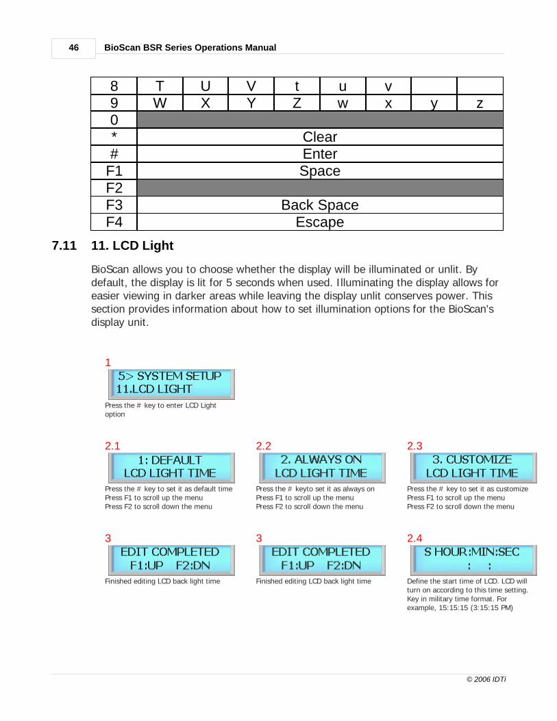
7.11 11. LCD Light
BioScan allows you to choose whether the display will be illuminated or unlit. Bydefault, the display is lit for 5 seconds when used. Illuminating the display allows foreasier viewing in darker areas while leaving the display unlit conserves power. Thissection provides information about how to set illumination options for the BioScan'sdisplay unit.
1
Press the # key to enter LCD Lightoption
2.1
Press the # key to set it as default timePress F1 to scroll up the menuPress F2 to scroll down the menu
2.2
Press the # keyto set it as always onPress F1 to scroll up the menuPress F2 to scroll down the menu
2.3
Press the # key to set it as customizePress F1 to scroll up the menuPress F2 to scroll down the menu
3
Finished editing LCD back light time
3
Finished editing LCD back light time
2.4
Define the start time of LCD. LCD willturn on according to this time setting.Key in military time format. Forexample, 15:15:15 (3:15:15 PM)
SYSTEM MENU 5 - SYSTEM SETUP 47
© 2006 IDTi
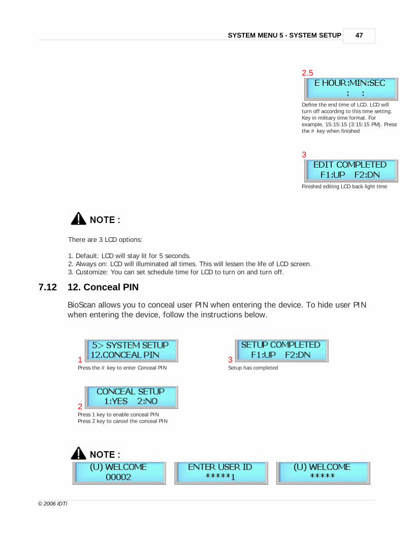
2.5
Define the end time of LCD. LCD willturn off according to this time setting.Key in military time format. Forexample, 15:15:15 (3:15:15 PM). Pressthe # key when finished
3
Finished editing LCD back light time
There are 3 LCD options:
1. Default: LCD will stay lit for 5 seconds.2. Always on: LCD will illuminated all times. This will lessen the life of LCD screen.3. Customize: You can set schedule time for LCD to turn on and turn off.
7.12 12. Conceal PIN
BioScan allows you to conceal user PIN when entering the device. To hide user PINwhen entering the device, follow the instructions below.
1Press the # key to enter Conceal PIN
3Setup has completed
2Press 1 key to enable conceal PINPress 2 key to cancel the conceal PIN

BioScan BSR Series Operations Manual48
© 2006 IDTi
Normal View Actual view during entrance Concealed User PIN View
7.13 13. Relay Board
7.14 14. Attendance
BioScan features option to display IN or OUT when function keys are used. Usermust be aware of the current attendance mode that is displayed in the standbydisplay. Last used attendance mode will be the default mode until the next mode isused. If F2-0 is used the last time, then unless second user uses a different functionkey, it will show as F2-0 even if second user do not press any function key. Thissection show how to customize the function key displays are shown.
1Press the # key to enter Date Format
4Press 1 to setup attendancePress 2 to cancel setup
2Press F1 key to scroll up the listPress F2 key to scroll down the list
5Setup has completed
3 Press the # key to enter Attendance.

BioScan BSC Series Operations Manual
Part
VIII

BioScan BSR Series Operations Manual50
© 2006 IDTi
8 SYSTEM MENU 6 - SCANNER SETUP
8.1 Re-Scanning
This is an operational mode whereby the reader repeatedly attempts to identify afingerprint on the optical unit. Access is not granted or rejected unless a finger isactually present on the optical unit. Default setting is set to 3 times and it canre-scan up to 9 times.
1Press the # key to enter Re-Scanning
3Finished setup
2"C" stands for current setting. Key in from 1 to 9
8.2 Level
This command sets both the security level that the reader will use when verifyingfingerprints and when identifying fingerprints. Security levels range from 1 to 7, with5 being the normal value for verification. The highest security setting is 7 and thelowest security setting is 1. Higher security access would normally require a highersecurity setting. For proper operation, the identification security level should be setto a value higher than the verification security level.
1Press the # key to enter Re-Scanning
3Finished setup
2"C" stands for current setting. Key in from 1 to 7.Default level is set to 5.

SYSTEM MENU 6 - SCANNER SETUP 51
© 2006 IDTi
8.3 Lighting Condition
This is an operational mode whereby the scanner sets the environment condition.There are 2 conditions available, OUTDOOR and INDOOR. Depending on the mode,scanner automatically adjust it self to the surrounding environment to enhance thescanning ability. Setting the right mode will greatly reduce the false rejection rate.
1Press the # key to enter LIGHTING CONDITION
3Finished setup
2Press 1 for OUTDOOR and press 2 for INDOOR use.Current mode is displayed in the bracket. <IN> or<OUT>
8.4 Enroll Mode
There are 2 types of enrollment procedures. Default is set to use mode 2 which is tois to enroll 1 templates per finger. Other way of enrolling the fingerprint is to usetype 1 which is to enroll 2 templates per finger. This type of enrollment will scansame finger twice.
1Press the # key to enter Enroll Mode
3Finished setup
2Press 1 for 2 fingerprint enrollmentPress 2 for 1 fingerprint enrollment
8.5 Identification Speed
The use of a new Identification Speed can accelerate the identification speed up to10 times at normal speed with relatively small degradation of authenticationaccuracy. The Identification Speed has 6 different levels from mode 1 to 6.

BioScan BSR Series Operations Manual52
© 2006 IDTi
1Press the # key to enter LIGHTING CONDITION
3Finished setup
2"C" stands for current setting. Key in from 1 to 6.Default is set to level 5.
Even though the performance degradation is not much, the fast mode does not needto be used in identification of small database, say less than 100 templates. In thatcase, the difference of matching time between a normal and a fast mode is notsignificant.

BioScan BSC Series Operations Manual
Part
IX

BioScan BSR Series Operations Manual54
© 2006 IDTi
9 USING THE BSR WITH BSC
9.1 BSC Connection
BSR SW3 must be set to RS232 as shown above.
9.2 Synchronizing Database
Once the connection is made to BSC-101, send user information such as fingerprint, card, userinformation from software to BSC-101. BSR will automatically be stored with same information BSCgets from the software thus making BSC and BSR sync with same user information.

BioScan BSC Series Operations Manual
Part
X

BioScan BSR Series Operations Manual56
© 2006 IDTi
10 INSTALLATION GUIDE
10.1 Connector Layout

INSTALLATION GUIDE 57
© 2006 IDTi
10.2 Power Connector

BioScan BSR Series Operations Manual58
© 2006 IDTi
10.3 RRE Connector

INSTALLATION GUIDE 59
© 2006 IDTi
10.4 RS232 Connector
SW3 must be set to RS232 as shown above.

BioScan BSR Series Operations Manual60
© 2006 IDTi
10.5 RS422 Connector
SW3 switch must be set to RS422.Make sure to cross the RX & TX data cable.

Index 61
© 2006 IDTi
Index- A -Address 38
Asia 43
Attendance 48
- B -baud rate 42
- C -Com. Speed 42
Communication Password 39
Conceal PIN 47
Custom Display 44
- D -Date Format 43
Delete All User 33
Delete Single User 33
display IN or OUT 48
- E -Edit User Card 23
Edit User Fingerprint 22
Edit User ID 22
Edit User Level 23
Edit User Name 24
Enroll Block of Card 18
Enroll Card 16
Enroll Card & Fingerprint 17
Enroll Fingerprint 15
Europe 43
Event Reset 41
Events 29
- F -facility code 39
Finger Version 30
firmware 30
function keys 48
- I -ID Option 25
INDOOR 51
- L -LCD Light 46
Lighting Condition 51
- N -Network ID 38
- O -Operating BioScan 8
Operating Funtion Key 10
Operating Mode 35
OUTDOOR 51
- P -Position 4
Pressure 4
- R -Re-Scanning 50
Rotation 4
- S -Security levels 50
Setting Operating Mode 37
Site Code 39
System Reset 40
- T -Time 35

BioScan BSR Series Operations Manual62
© 2006 IDTi
- U -unique identification code 38
USA 43
User List 28