
Biometric authenticationusing digital retinal images … · Biometric authenticationusing digital...
6
Biometric authentication using digital retinal images M. ORTEGA, C.MARI ˜ NO, M.G.PENEDO, M.BLANCO, F.GONZ ´ ALEZ † Grupo de Visi´ on Artificial y Reconocimiento de Patrones University of A Coru˜ na Campus de Elvi˜ na s/n, A Coru ˜ na, 15071 † University of Santiago de Compostela † School of Medicine andComplejo Hospitalario Universitario of Santiago, 15782 Santiago de Compostela SPAIN Abstract: In this work an efficient method for the identity verification of persons based on matching digital retinal images is introduced. The matching process works by extracting a set of feature points and registering them to measure the degree of similarity between the input images. The feature points are the ridge endings and ridge bifurcations from vessels obtained from a crease model of the retinal vessels. The method is developed and tested to obtain a good set of feature points. Then, pairs of sets will be matched in order to get an accurate and reliable similarity measure for the authentication procedure. Key–Words: Biometric authentication, registration, similarity measure, optic disc. 1 Introduction Reliable authentication of persons is a growing de- manding service in many fields, not only in police or military environments, but also in civilian appli- cations, such as access control or financial transac- tions. Traditional authentication systems are based on knowledge (a password, a pin) or possession (a card, a key). But these systems are not reliable enough for many environments, due to their common inability to differentiate between a true authorized user and an user who fraudulently acquired the privilege of the au- thorized user. A solution to these problems has been found in the biometric based authentication technolo- gies. A biometric system is a pattern recognition sys- tem that establishes the authenticity of a specific phys- iological or behavioral characteristic. Identification can be in the form of authentication (identity verifica- tion), verification (authenticating a claimed identity) or recognition (determination of an identity from a database of known people, this is, determining who a person is without knowledge of his/her name). Many authentication technologies can be found in the literature [1–4]. But, nowadays, the most of the efforts in authentication systems tend to develop more secure environments, where it is harder, or ideally, im- possible, to create a copy of the properties used by the system do discriminate between authorized and unau- thorized individuals. This paper proposes a biometric system for au- thentication that uses the blood vessel pattern. This is a unique pattern in each individual and it is almost impossible to forge that pattern in a false individual. Of course, the pattern does not change through the in- dividual’s life, unless a pathology appears in the eye. This biometric parameter has already shown to be a good choice in [5, 6]. In this paper, a more compact representation of the retinal vessel tree is employed. Classical fingerprint authentication methods rely on representing the two most prominent structures: ridge endings and and ridge bifurcations [1, 7]. In this work, the same landmarks are extracted and employed as the template that characterizes an individual in the system. In a first stage of our method, the extraction of the features to use as anatomical landmarks takes place. In our case, these features will be the ridge endings and ridge bifurcations of the whole retinal vessel tree extracted from a set of crest and valley lines. This technique is very similar to the methodology used in the fingerprint based authentication [8]. Once that pat- tern has been obtained, it is stored in a database of authorized people. When a person needs to be au- thenticated, the acquired image is processed to extract the set of feature points, and a registration method aligns these points with the pattern stored from this individual. For a review of medical image registra- tion methods see [9]). The registration process is nec- essary due to inevitable eye movements that must be corrected prior to the application of quantitative anal- ysis. Once the images are aligned, a similarity mea- sure can be computed. If this measure is higher than a Proceedings of the 5th WSEAS International Conference on Applied Computer Science, Hangzhou, China, April 16-18, 2006 (pp422-427)
Transcript of Biometric authenticationusing digital retinal images … · Biometric authenticationusing digital...
Biometric authentication using digital retinal images
M. ORTEGA, C.MARINO, M.G.PENEDO, M.BLANCO, F.GONZALEZ†
Grupo de Vision Artificial y Reconocimiento de PatronesUniversity of A Coruna
Campus de Elvina s/n, A Coruna, 15071†University of Santiago de Compostela
†School of Medicine andComplejo Hospitalario Universitario of Santiago, 15782 Santiago de CompostelaSPAIN
Abstract: In this work an efficient method for the identity verification of persons based on matching digital retinalimages is introduced. The matching process works by extracting a set of feature points and registering them tomeasure the degree of similarity between the input images. The feature points are the ridge endings and ridgebifurcations from vessels obtained from a crease model of the retinal vessels. The method is developed and testedto obtain a good set of feature points. Then, pairs of sets will be matched in order to get an accurate and reliablesimilarity measure for the authentication procedure.
Key–Words: Biometric authentication, registration, similarity measure, optic disc.
1 Introduction
Reliable authentication of persons is a growing de-manding service in many fields, not only in policeor military environments, but also in civilian appli-cations, such as access control or financial transac-tions. Traditional authentication systems are basedon knowledge (a password, a pin) or possession (acard, a key). But these systems are not reliable enoughfor many environments, due to their common inabilityto differentiate between a true authorized user and anuser who fraudulently acquired the privilege of the au-thorized user. A solution to these problems has beenfound in the biometric based authentication technolo-gies. A biometric system is a pattern recognition sys-tem that establishes the authenticity of a specific phys-iological or behavioral characteristic. Identificationcan be in the form of authentication (identity verifica-tion), verification (authenticating a claimed identity)or recognition (determination of an identity from adatabase of known people, this is, determining whoa person is without knowledge of his/her name).
Many authentication technologies can be found inthe literature [1–4]. But, nowadays, the most of theefforts in authentication systems tend to develop moresecure environments, where it is harder, or ideally, im-possible, to create a copy of the properties used by thesystem do discriminate between authorized and unau-thorized individuals.
This paper proposes a biometric system for au-thentication that uses the blood vessel pattern. This
is a unique pattern in each individual and it is almostimpossible to forge that pattern in a false individual.Of course, the pattern does not change through the in-dividual’s life, unless a pathology appears in the eye.This biometric parameter has already shown to be agood choice in [5, 6]. In this paper, a more compactrepresentation of the retinal vessel tree is employed.
Classical fingerprint authentication methods relyon representing the two most prominent structures:ridge endings and and ridge bifurcations [1,7]. In thiswork, the same landmarks are extracted and employedas the template that characterizes an individual in thesystem.
In a first stage of our method, the extraction of thefeatures to use as anatomical landmarks takes place.In our case, these features will be the ridge endingsand ridge bifurcations of the whole retinal vessel treeextracted from a set of crest and valley lines. Thistechnique is very similar to the methodology used inthe fingerprint based authentication [8]. Once that pat-tern has been obtained, it is stored in a database ofauthorized people. When a person needs to be au-thenticated, the acquired image is processed to extractthe set of feature points, and a registration methodaligns these points with the pattern stored from thisindividual. For a review of medical image registra-tion methods see [9]). The registration process is nec-essary due to inevitable eye movements that must becorrected prior to the application of quantitative anal-ysis. Once the images are aligned, a similarity mea-sure can be computed. If this measure is higher than a
Proceedings of the 5th WSEAS International Conference on Applied Computer Science, Hangzhou, China, April 16-18, 2006 (pp422-427)
given threshold, the individual is accepted, otherwisethe individual is rejected.
2 Feature points extraction
As stated above, the biometric parameter used by theproposed system is the whole retinal vessel tree, ex-tracted from digital retinal images. In order to re-duce the computational time, only a set of points isextracted and used to register the images and performthe authentication test, without a loss of accuracy orreliability. The point extraction is performed in threesteps: (1) Creases extraction, (2) optic nerve extrac-tion and (3) feature point extraction. Each stage isdescribed in the following sections.
2.1 Creases extractionVessels are reliable landmarks in retinal images be-cause they are almost rigid structures and they appearin all modalities. Moreover, they can be thought ofas creases (ridges or valleys) when images are seen aslandscapes.
Among the many definitions of a crease, the onebased on level set extrinsic curvature (LSEC), has use-ful invariance properties. Given a function L : IRd →IR, the level set for a constant l consists of the set ofpoints {x|L(x) = l}. For 2D images, L can be consid-ered as a topographic relief or landscape and the levelsets as its level curves. Negative minima of the levelcurve curvature κ, level by level, form valley curves,and positive maxima form ridge curves.
However, the usual discretization of LSEC is ill–defined in a number of cases, giving rise to unexpecteddiscontinuities at the center of elongated objects. Dueto this, we have employed the MLSEC−ST operator,defined in [10] and [11] for 3–D landmark extractionof CT and MRI volumes. This alternative definition isbased on the divergence of the normalized vector fieldw:
κ = −div(w) (1)
The creaseness measure κ can still be improvedby pre–filtering the image gradient vector field in or-der to increase the degree of attraction/repulsion atridge–like/valley–like creases as this is what κ ac-tually measures. This can be done by the follow-ing structure tensor analysis: (1) Compute the gra-dient vector field w and the structure tensor field MM(x;σI) = G(x;σI) ∗ (w(x) · w(x)t), where ∗ is theelement–wise convolution of matrix w(x) ·w(x)t withthe Gaussian window G(x;σI). (2) Perform the eigen-value analysis of M. The normalized eigenvector w′
corresponding to the highest eigenvalue gives the pre-dominant gradient orientation. In the structure ten-sor analysis, opposite directions are equally treated.Thus, to recover the direction w′ is located in the samequadrant in 2–d, or octant in 3–d, as w. Then, the newvector field w and the creaseness measure κd are com-puted as:
w = sign(w′tw)w′ (2)
κ = −div(w) (3)
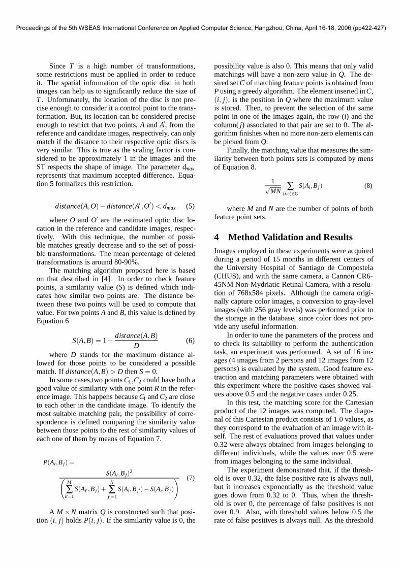
Figure 1 left, shows the result of the creases ex-traction algorithm.
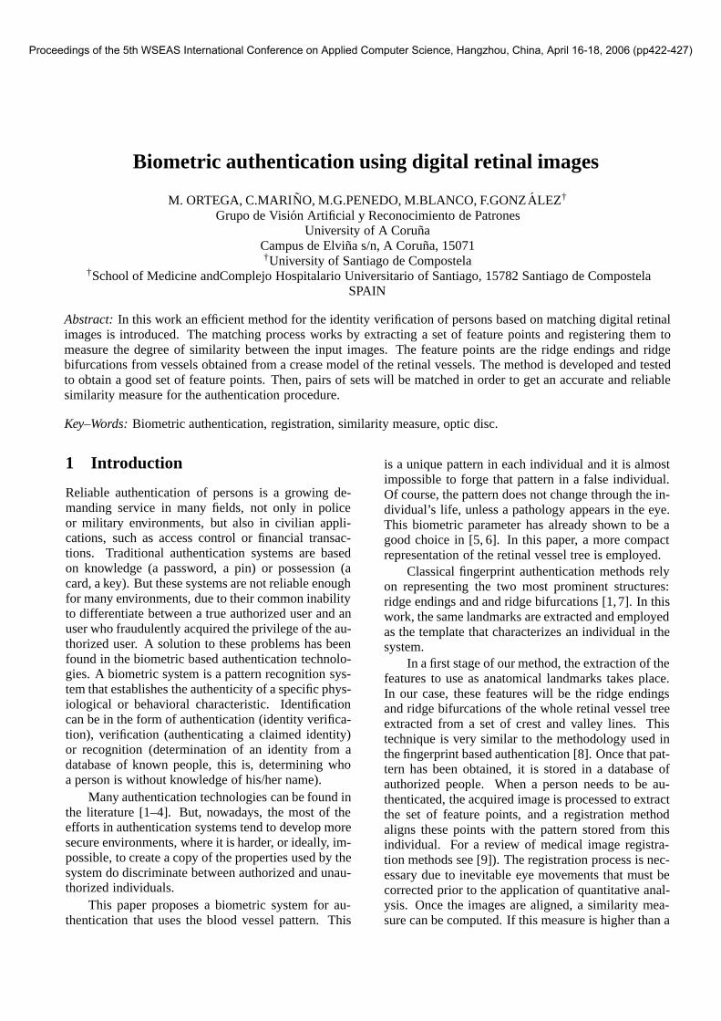
2.2 Optic disc extractionThe optic disc is the brightest area in the digital reti-nal images, with an almost circular shape. It is theentrance region of the vessels and its detection is veryimportant as it works as a landmark for the other fea-tures in the retinal image. To determine the positionof the optic disc, a two-stage algorithm is used: in thefirst stage, the area (region of interest) where the opticdisc is located is determined (Figure 1, center). Then,the fuzzy circular Hough transform is applied to theedges of the region in order to extract the optic disc.The fuzzy circular Hough transform might not extractthe disc due to the fact that there are vessels inside theoptic disc. In order to eliminate the circles belong-ing to vessel edges, the vessel edge points are elimi-nated. To this end, an automatic vessel extraction isperformed by the algorithm described in section 2.1.Once the crease image in the region of interest is com-puted by the previous process, the edge vessels are re-moved. If an edge point (xi,yi) belongs to a vessel, anwa ×wb neighborhood window centered at the creasepoint is considered in the edge image. If the direc-tion of an edge point in the window is analogous tothe direction of the crease point, this edge point is re-moved. Figure 1,right, depicts the results obtained bythis algorithm on a retinal image [12].
Fig 1: Left: result of the creases extraction. Center: result ofthe region of interest computation. Right: result of the optic discsegmentation process.
2.3 Point extractionOnce the creases image and the optic disc positionhave been computed, the feature point search stage be-
Proceedings of the 5th WSEAS International Conference on Applied Computer Science, Hangzhou, China, April 16-18, 2006 (pp422-427)
gins. As already stated, the feature points are the ridgeendings and bifurcations of the creases. In this paper,the term ’bifurcation’ refers to any of both kind of fea-ture points since they are all extracted in the same way.
To make an efficient approach to the problem, in-stead of tracking the segments trying to find featurepoints along them in a given radius, only the environ-ment around the creases segment extremes will be an-alyzed.
Still another problem must be solved prior to thefeature point extraction: the creases segments fromthe same vessel sometimes appear as different seg-ments. So, relationships between segments will beestablished in order to build the retinal vessel tree.The two kind of relationships to take into account areunions (a segment is the continuation of another one,belonging both to the same vessel) and bifurcations (asegment, coming out of another segment, starts a newvessel).
Our feature points extraction algorithm has thefollowing stages: (1) Segment detection, (2) segmentunion detection, (3) segment bifurcation candidatesdetection and finally, (4) feature point set extraction.
In order to obtain the segments in the image, asimple but very efficient algorithm is used. The entirecreases image is tracked and when a non-zero pixelis found, the disposition of its four possible neighborsis analyzed (since the image tracking is from left toright and from top to bottom, upper neighbors and leftneighbor are always zero), and in any of the 8 possiblecases the segment pixels are accordingly tracked.
As later we will have to deal with the segmentsdirections, each point is assigned a predecessor and asuccessor, to specify its direction. Also, the endingsare accordingly labelled as the start and the end of thesegment. If the set directions are not right, they willbe corrected in a next stage. The purpose of establish-ing these directions at this stage is to have a referencedirection to use in further analysis.
The unions between segments are important in or-der to build the whole vessel tree, because they allowto continue the vessels and propagate the correct di-rection to the bifurcation segment candidates.
A union is a relationship between two endpointsof different segments. A union is accepted as rightwhen the endpoints are close to each other, and, ofcourse, a segment represents the continuation of theother. This means that they must have similar orien-tations and the connection between them should besmooth.
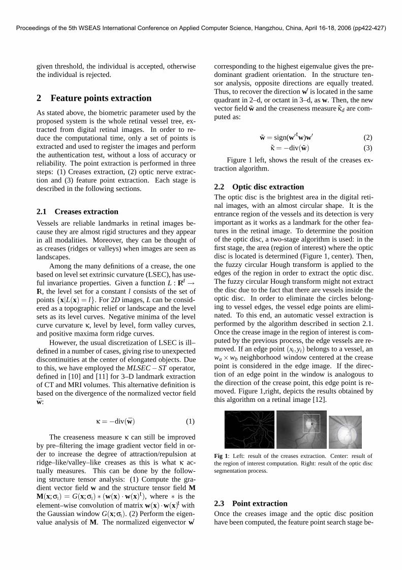
From the experiments run, it was observed thatconnecting both segments through a straight line isenough to determine the likelihood of that union tobelong to the same crease, as depicted in Figure 2.The closer to 180◦ the angles of the segments are, the
smoother the union is. An angle threshold θ is nec-essary to discard wrong unions. Values of θ close to135◦ deliver good results in the vast majority of thecases.
r
sAB sα
β
rA
B
Fig 2: Left: Union of creases segments r and s. Right: the anglesbetween the new segment AB and the creases segments r (α) ands (β) are near πrad so they are above the required threshold (3
4 π)and the union is finally accepted.
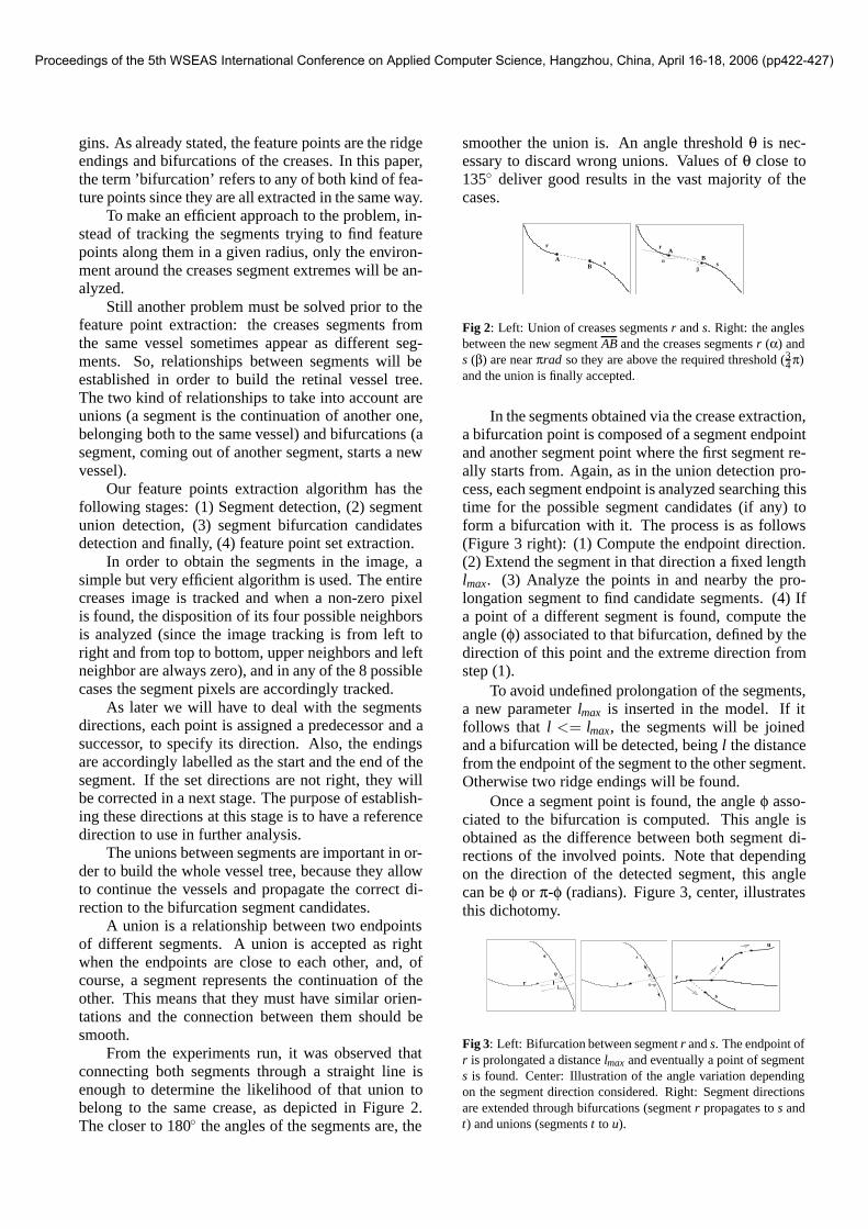
In the segments obtained via the crease extraction,a bifurcation point is composed of a segment endpointand another segment point where the first segment re-ally starts from. Again, as in the union detection pro-cess, each segment endpoint is analyzed searching thistime for the possible segment candidates (if any) toform a bifurcation with it. The process is as follows(Figure 3 right): (1) Compute the endpoint direction.(2) Extend the segment in that direction a fixed lengthlmax. (3) Analyze the points in and nearby the pro-longation segment to find candidate segments. (4) Ifa point of a different segment is found, compute theangle (φ) associated to that bifurcation, defined by thedirection of this point and the extreme direction fromstep (1).
To avoid undefined prolongation of the segments,a new parameter lmax is inserted in the model. If itfollows that l <= lmax, the segments will be joinedand a bifurcation will be detected, being l the distancefrom the endpoint of the segment to the other segment.Otherwise two ridge endings will be found.
Once a segment point is found, the angle φ asso-ciated to the bifurcation is computed. This angle isobtained as the difference between both segment di-rections of the involved points. Note that dependingon the direction of the detected segment, this anglecan be φ or π-φ (radians). Figure 3, center, illustratesthis dichotomy.
s
r
ϕl
lmaxr
s
ϕ
π−ϕr
s
t
u
Fig 3: Left: Bifurcation between segment r and s. The endpoint ofr is prolongated a distance lmax and eventually a point of segments is found. Center: Illustration of the angle variation dependingon the segment direction considered. Right: Segment directionsare extended through bifurcations (segment r propagates to s andt) and unions (segments t to u).
Proceedings of the 5th WSEAS International Conference on Applied Computer Science, Hangzhou, China, April 16-18, 2006 (pp422-427)
The direction will determine if this candidate bi-furcation is finally accepted or discarded. In the laststage, final segment directions are established allow-ing to decide whether the feature point candidates areaccepted or rejected. Due to this, a value associatedto each candidate is stored at this stage, indicating thedirection of the segment.
In order to determine the right directions of thesegments, the whole retinal vessel tree is built fromthe segments starting at the optic disc and propagatingthe directions through the bifurcations and junctions.
As the location of the optic disc is known, a cir-cle around the disc can be drawn. Tracking this circlethe segments that intersect with the circle will be ob-tained. These are the initial segments of the process.The right direction of these segments is set as the start-ing endpoint in contact with the optic disc) and then,for each one of them, bifurcation candidates are ana-lyzed. If the direction of the candidate branch to beaccepted is adequate, the bifurcation is accepted andthe direction is propagated to the other segment form-ing that bifurcation. Recursively, directions are prop-agated through bifurcations and unions. An exampleis shown in Figure 3, right.
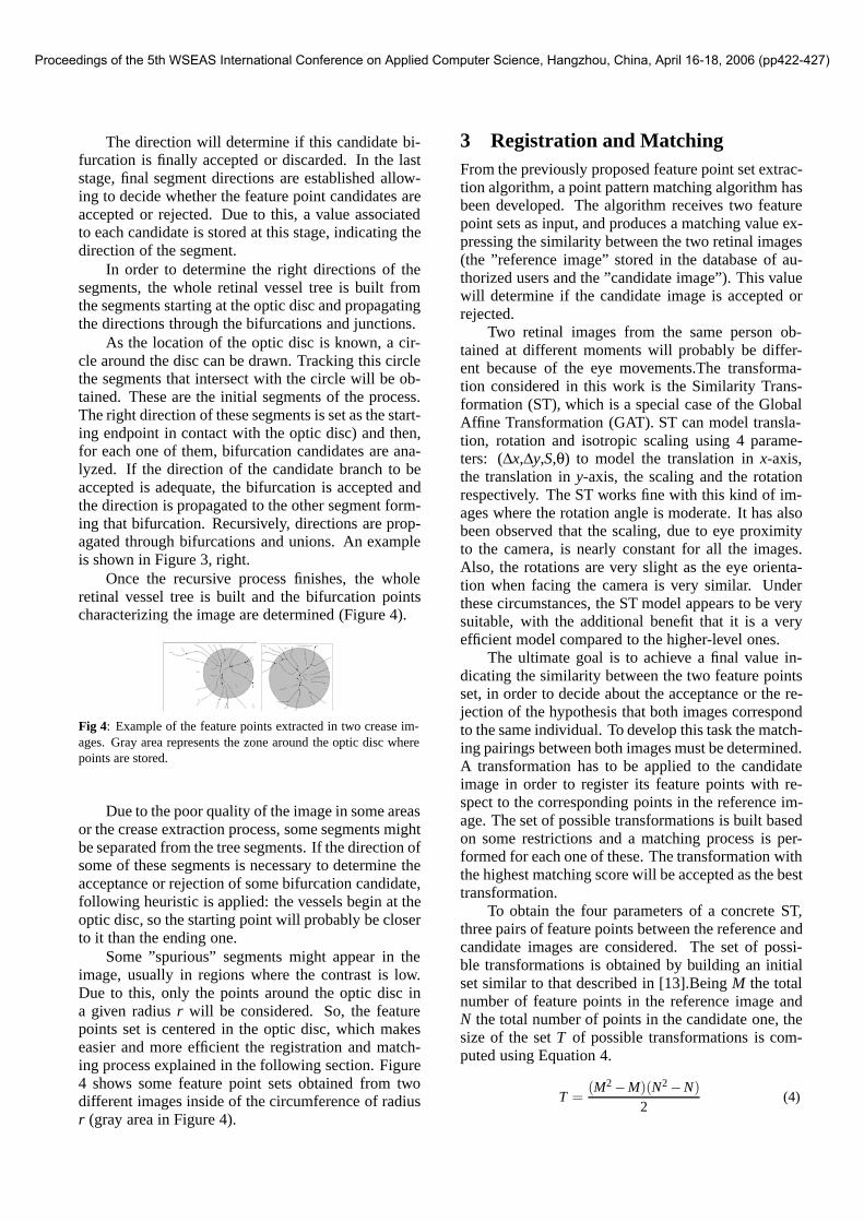
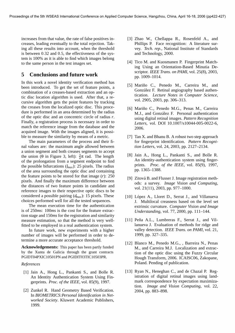
Once the recursive process finishes, the wholeretinal vessel tree is built and the bifurcation pointscharacterizing the image are determined (Figure 4).
Fig 4: Example of the feature points extracted in two crease im-ages. Gray area represents the zone around the optic disc wherepoints are stored.
Due to the poor quality of the image in some areasor the crease extraction process, some segments mightbe separated from the tree segments. If the direction ofsome of these segments is necessary to determine theacceptance or rejection of some bifurcation candidate,following heuristic is applied: the vessels begin at theoptic disc, so the starting point will probably be closerto it than the ending one.
Some ”spurious” segments might appear in theimage, usually in regions where the contrast is low.Due to this, only the points around the optic disc ina given radius r will be considered. So, the featurepoints set is centered in the optic disc, which makeseasier and more efficient the registration and match-ing process explained in the following section. Figure4 shows some feature point sets obtained from twodifferent images inside of the circumference of radiusr (gray area in Figure 4).
3 Registration and MatchingFrom the previously proposed feature point set extrac-tion algorithm, a point pattern matching algorithm hasbeen developed. The algorithm receives two featurepoint sets as input, and produces a matching value ex-pressing the similarity between the two retinal images(the ”reference image” stored in the database of au-thorized users and the ”candidate image”). This valuewill determine if the candidate image is accepted orrejected.
Two retinal images from the same person ob-tained at different moments will probably be differ-ent because of the eye movements.The transforma-tion considered in this work is the Similarity Trans-formation (ST), which is a special case of the GlobalAffine Transformation (GAT). ST can model transla-tion, rotation and isotropic scaling using 4 parame-ters: (∆x,∆y,S,θ) to model the translation in x-axis,the translation in y-axis, the scaling and the rotationrespectively. The ST works fine with this kind of im-ages where the rotation angle is moderate. It has alsobeen observed that the scaling, due to eye proximityto the camera, is nearly constant for all the images.Also, the rotations are very slight as the eye orienta-tion when facing the camera is very similar. Underthese circumstances, the ST model appears to be verysuitable, with the additional benefit that it is a veryefficient model compared to the higher-level ones.
The ultimate goal is to achieve a final value in-dicating the similarity between the two feature pointsset, in order to decide about the acceptance or the re-jection of the hypothesis that both images correspondto the same individual. To develop this task the match-ing pairings between both images must be determined.A transformation has to be applied to the candidateimage in order to register its feature points with re-spect to the corresponding points in the reference im-age. The set of possible transformations is built basedon some restrictions and a matching process is per-formed for each one of these. The transformation withthe highest matching score will be accepted as the besttransformation.
To obtain the four parameters of a concrete ST,three pairs of feature points between the reference andcandidate images are considered. The set of possi-ble transformations is obtained by building an initialset similar to that described in [13].Being M the totalnumber of feature points in the reference image andN the total number of points in the candidate one, thesize of the set T of possible transformations is com-puted using Equation 4.
T =(M2 −M)(N2 −N)
2(4)
Proceedings of the 5th WSEAS International Conference on Applied Computer Science, Hangzhou, China, April 16-18, 2006 (pp422-427)
Since T is a high number of transformations,some restrictions must be applied in order to reduceit. The spatial information of the optic disc in bothimages can help us to significantly reduce the size ofT . Unfortunately, the location of the disc is not pre-cise enough to consider it a control point to the trans-formation. But, its location can be considered preciseenough to restrict that two points, A and A′, from thereference and candidate images, respectively, can onlymatch if the distance to their respective optic discs isvery similar. This is true as the scaling factor is con-sidered to be approximately 1 in the images and theST respects the shape of image. The parameter dmaxrepresents that maximum accepted difference. Equa-tion 5 formalizes this restriction.
distance(A,O)−distance(A′ ,O′) < dmax (5)
where O and O′ are the estimated optic disc lo-cation in the reference and candidate images, respec-tively. With this technique, the number of possi-ble matches greatly decrease and so the set of possi-ble transformations. The mean percentage of deletedtransformations is around 80-90%.
The matching algorithm proposed here is basedon that described in [4]. In order to check featurepoints, a similarity value (S) is defined which indi-cates how similar two points are. The distance be-tween these two points will be used to compute thatvalue. For two points A and B, this value is defined byEquation 6
S(A,B) = 1− distance(A,B)D
(6)
where D stands for the maximum distance al-lowed for those points to be considered a possiblematch. If distance(A,B) > D then S = 0.
In some cases,two points C1,C2 could have both agood value of similarity with one point R in the refer-ence image. This happens because C1 and C2 are closeto each other in the candidate image. To identify themost suitable matching pair, the possibility of corre-spondence is defined comparing the similarity valuebetween those points to the rest of similarity values ofeach one of them by means of Equation 7.
P(Ai,B j) =
S(Ai,B j)2(M
∑i′=1
S(Ai′ ,B j)+N
∑j′=1
S(Ai,B j′)−S(Ai,B j)
) (7)
A M ×N matrix Q is constructed such that posi-tion (i, j) holds P(i, j). If the similarity value is 0, the
possibility value is also 0. This means that only validmatchings will have a non-zero value in Q. The de-sired set C of matching feature points is obtained fromP using a greedy algorithm. The element inserted in C,(i, j), is the position in Q where the maximum valueis stored. Then, to prevent the selection of the samepoint in one of the images again, the row (i) and thecolumn( j) associated to that pair are set to 0. The al-gorithm finishes when no more non-zero elements canbe picked from Q.
Finally, the matching value that measures the sim-ilarity between both points sets is computed by mensof Equation 8.
1√MN
∑(i,c)∈C
S(Ai,B j) (8)
where M and N are the number of points of bothfeature point sets.
4 Method Validation and ResultsImages employed in these experiments were acquiredduring a period of 15 months in different centers ofthe University Hospital of Santiago de Compostela(CHUS), and with the same camera, a Cannon CR6-45NM Non-Mydriatic Retinal Camera, with a resolu-tion of 768x584 pixels. Although the camera origi-nally capture color images, a conversion to gray-levelimages (with 256 gray levels) was performed prior tothe storage in the database, since color does not pro-vide any useful information.
In order to tune the parameters of the process andto check its suitability to perform the authenticationtask, an experiment was performed. A set of 16 im-ages (4 images from 2 persons and 12 images from 12persons) is evaluated by the system. Good feature ex-traction and matching parameters were obtained withthis experiment where the positive cases showed val-ues above 0.5 and the negative cases under 0.25.
In this test, the matching score for the Cartesianproduct of the 12 images was computed. The diago-nal of this Cartesian product consists of 1.0 values, asthey correspond to the evaluation of an image with it-self. The rest of evaluations proved that values under0.32 were always obtained from images belonging todifferent individuals, while the values over 0.5 werefrom images belonging to the same individual.
The experiment demonstrated that, if the thresh-old is over 0.32, the false positive rate is always null,but it increases exponentially as the threshold valuegoes down from 0.32 to 0. Thus, when the thresh-old is over 0, the percentage of false positives is notover 0.9. Also, with threshold values below 0.5 therate of false positives is always null. As the threshold
Proceedings of the 5th WSEAS International Conference on Applied Computer Science, Hangzhou, China, April 16-18, 2006 (pp422-427)
increases from that value, the rate of false positives in-creases, leading eventually to the total rejection. Tak-ing all these results into account, when the thresholdis between 0.32 and 0.5, the effectiveness of the sys-tem is 100% as it is able to find which images belongto the same person in the test images set.
5 Conclusions and future workIn this work a novel identity verification method hasbeen introduced. To get the set of feature points, acombination of a creases-based extraction and an op-tic disc location algorithm is used. After that, a re-cursive algorithm gets the point features by trackingthe creases from the localized optic disc. This proce-dure is performed in an area determined by the radiusof the optic disc and an concentric circle of radius r.Finally, a registration process is necessary in order tomatch the reference image from the database and theacquired image. With the images aligned, it is possi-ble to measure the similarity by means of a metric.
The main parameters of the process and their fi-nal values are: the maximum angle allowed betweena union segment and both creases segments to acceptthe union (θ in Figure 3, left): 3
4π rad. The lengthof the prolongation from a segment endpoint to findthe possible bifurcations (lmax): 25 pixels. The radiusof the area surrounding the optic disc and containingthe feature points to be stored for that image (r): 250pixels. And finally the maximum difference betweenthe distances of two feature points in candidate andreference images to their respective optic discs to beconsidered a possible pairing (dmax): 15 pixels. Thesechoices performed well for all the tested sequences.
The mean execution time for the authenticationis of 250ms: 100ms is the cost for the feature extrac-tion stage and 150ms for the registration and similaritymeasure estimation, so that the method is very well-fitted to be employed in a real authentication system.
In future work, new experiments with a highernumber of images will be performed in order to de-termine a more accurate acceptance threshold.
Acknowledgements: This paper has been partly fundedby the Xunta de Galicia through the grant contractsPGIDT04PXIC10501PN and PGIDIT03TIC10503PR.
References
[1] Jain A., Hong L., Pankanti S., and Bolle R.An Identity Authentication System Using Fin-gerprints. Proc. of the IEEE, vol. 85(9), 1997.
[2] Zunkel R. Hand Geometry Based Verification.In BIOMETRICS:Personal Identification in Net-worked Society. Kluwert Academic Publishers,1999.
[3] Zhao W., Chellappa R., Rosenfeld A., andPhillips P. Face recognition: A literature sur-vey. Tech. rep., National Institute of Standardsand Technology, 2000.
[4] Tico M. and Kuosmanen P. Fingerprint Match-ing Using an Orientation-Based Minutia De-scriptor. IEEE Trans. on PAMI, vol. 25(8), 2003,pp. 1009–1014.
[5] Marino C., Penedo M., Carreira M., andGonzalez F. Retinal angiography based authen-tication. Lecture Notes in Computer Science,vol. 2905, 2003, pp. 306–313.
[6] Marino C., Penedo M.G., Penas M., CarreiraM.J., and Gonzalez F. Personal authenticationusing digital retinal images. Pattern RecognitionLetters, vol. DOI 10.1007/s10044-005-0022-6,2006.
[7] Tan X. and Bhanu B. A robust two step approachfor fingerprint identification. Pattern Recogni-tion Letters, vol. 24, 2003, pp. 2127–2134.
[8] Jain A., Hong L., Pankanti S., and Bolle R.An identity-authentication system using finger-prints. Proc. of the IEEE, vol. 85(9), 1997,pp. 1365–1388.
[9] Zitova B. and Flusser J. Image registration meth-ods: a survey. Image Vision and Computing,vol. 21(11), 2003, pp. 977–1000.
[10] Lopez A., Lloret D., Serrat J., and VillanuevaJ. Multilocal creasness based on the level setextrinsic curvature. Computer Vision and ImageUnderstanding, vol. 77, 2000, pp. 111–144.
[11] Pena A.L., Lumbreras F., Serrat J., and Vil-lanueva J. Evaluation of methods for ridge andvalley detection. IEEE Trans. on PAMI, vol. 21,1999, pp. 327–335.
[12] Blanco M., Penedo M.G., , Barreira N., PenasM., and Carreira M.J. Localization and extrac-tion of the optic disc using the Fuzzy CircularHough Transform, 2006. ICAISC06, Zakopane,Poland. Pending of publication.
[13] Ryan N., Heneghan C., and de Chazal P. Reg-istration of digital retinal images using land-mark correspondence by expectation maximiza-tion. Image and Vision Computing, vol. 22,2004, pp. 883–898.
Proceedings of the 5th WSEAS International Conference on Applied Computer Science, Hangzhou, China, April 16-18, 2006 (pp422-427)