BIOMETRIC AUTHENTICATION SYSTEM FOR SECURE DIGITAL …dde.binghamton.edu/blythe/SDC.pdf ·...
120
BIOMETRIC AUTHENTICATION SYSTEM FOR SECURE DIGITAL CAMERAS BY PAUL A. BLYTHE SR. AAS, Broome Community College, 1976 BS, Binghamton University, State University of New York, 1982 MS, Binghamton University, State University of New York, 2001 DISSERTATION Submitted in partial fulfillment of the requirements for the degree of Doctor of Philosophy in Systems Science in the Graduate School of Binghamton University State University of New York 2005
Transcript of BIOMETRIC AUTHENTICATION SYSTEM FOR SECURE DIGITAL …dde.binghamton.edu/blythe/SDC.pdf ·...

BIOMETRIC AUTHENTICATION SYSTEM FOR SECURE DIGITAL CAMERAS
BY
PAUL A. BLYTHE SR.
AAS, Broome Community College, 1976 BS, Binghamton University, State University of New York, 1982 MS, Binghamton University, State University of New York, 2001
DISSERTATION
Submitted in partial fulfillment of the requirements for the degree of Doctor of Philosophy in Systems Science
in the Graduate School of Binghamton University
State University of New York 2005

2005 by Paul A. Blythe Sr. All rights reserved.
ii

Accepted in partial fulfillment of the requirements for the degree of Doctor of Philosophy in Systems Science
in the Graduate School of Binghamton University
State University of New York 2005
May 6, 2005
Harold Lewis, Department of Systems Science & Industrial Engineering, Binghamton University
George Klir, Department of Systems Science & Industrial Engineering, Binghamton University
Jessica Fridrich, Department of Electrical & Computer Engineering, Binghamton University
Rebecca Bussjager, Air Force Research Laboratory–SNDP, Rome, NY
iii
ABSTRACT
Digital camera images are not easily accepted as evidence because it is difficult
for law enforcement, insurance, news, and other such agencies to authenticate their
integrity, origin, and authorship. The integrity of digital images as evidence rests on the
accurate answering of a simple question: Who did what when?
The unique (Proof of concept) research, presented in this dissertation involved
developing the first of its kind, Biometric Authentication System (BAS), for a Secure
Digital Camera (SDC), to solve the following significant problems currently associated
with the use of digital images as evidence, such as:
Verifying the digital camera image was not damaged or tampered with. (Integrity)
Identifying exactly what camera captured the digital image. (Origin)
Exact identification of the digital photographer. (Authorship)
The concept of this invisible, inside the camera solution, involves losslessly
embedding a biometric identifier (The photographer’s iris), with cryptographic hashes,
and other forensic data, concurrently into the original scene image.
The biometric identifier (The photographer’s iris) is captured through the SDC
viewfinder when the shutter release button is depressed to take the original scene image.
The motivation for this concept was a presentation given by Dr. Jessica Fridrich,
at Binghamton University (September, 2000). Fridrich referenced a scenario of a special
tamper–proof watermarking chip inside a digital camera that would secretly watermark
the image data before it is stored in the camera’s memory i.
An overview of the concepts behind the SDC is given, and previous research
summarized. The solutions to problems encountered in developing a SDC are detailed.
iv

To My Parents
Gerald and Helen Blythe
v

ACKNOWLEDGMENTS
It is with respect and appreciation that I acknowledge my committee members,
Hal Lewis, Jessica Fridrich, George Klir, and Rebecca Bussjager for their invaluable
support, assistance, and encouragement, throughout my dissertation research project. I
also wish to thank my Professors Hal Lewis, Jessica Fridrich, and George Klir, for
providing me the opportunity to attend their enlightening and enjoyable courses, as well
as tailoring my independent study courses to support and guide me in my research efforts.
I am especially indebted to Jessica Fridrich, for the inspiration her enlightening
presentations and innovative publications i, v, xx in the fields of digital watermarking,
steganography, and data encryption gave me. For they initiated my intense, interest in
their applications to digital forensics and security. Her support and encouragement
enabled me to acquire the knowledge necessary to pursue my interests. This dissertation
incorporates one of the unique lossless watermarking embedding and extraction
techniques she pioneered xxix.
I am equally indebted to Professor Lewis, for his extraordinary dedication and
love of teaching. During my first year at Binghamton University, Professor Lewis
voluntarily offered me a study plan to refresh my knowledge in applied calculus. He
offered this same opportunity to another “math rusty” student, and my good friend,
Roberto Duran–Rodriguez. He then regularly returned to the campus during his summer
break to assist both of us in successfully achieving our summer study goals.
To my family and friends, who I have seen so little during the past several years, I
offer to them all a big “Thank You” for their continuing patience and understanding. I am
very fortunate to have so many dear friends. However, I cannot list you all, for this
vi

section would read like a telephone book. Each of you knows how much your support has
meant to me. No words can properly express my sincere gratitude.
To Ms. Zhongtao Feng, my ever-lasting appreciation for her initial
encouragement to pursue my doctorial studies.
Special thanks belong to Ms. Rebecca Bussjager ii, from the AFRL/SNDP (Air
Force Research Lab) at Rome, NY for her help with the various optical problems I
encountered.
Very special thanks to Ms. Judy Zhu, for her help and support during the most
stressful phase of this dissertation, its completion, and review.
To Dr. John Daugman go my very sincere thanks. Not only for his encouragement
and patience. But for his expert opinions, and helpful suggestions. Daugman made the
difficult task of capturing an iris image with the resolution and contrast necessary for iris
recognition, a reality.
In conclusion, I wish to thank my committee members for taking the time to
review this dissertation and for their help and support at my defense.
This dissertation research was supported by Air Force Research Laboratory, Air
Force Material Command, USAF, under the grant number F30602-02-2-0093.
The U.S. Government is authorized to reproduce and distribute reprints for
Governmental purposes notwithstanding any copyright notation there on. The views and
conclusions contained herein are those of the authors and should not be interpreted as
necessarily representing the official policies, either expressed or implied, of Air Force
Research Laboratory, or the U. S. Government.
vii
TABLE OF CONTENTS
Abstract .............................................................................................................................. iv Acknowledgments.............................................................................................................. vi Table of Contents............................................................................................................. viii List of Tables ...................................................................................................................... x Table of Figures ................................................................................................................. xi Acronyms.......................................................................................................................... xii Notational Conventions ................................................................................................... xiv 1. Introduction................................................................................................................. 1
1.1. Motivation and Background ....................................................................... 1 1.2. Scope and Contributions ............................................................................. 3
1.2.1. Scope........................................................................................................... 3 1.2.2. Contributions............................................................................................... 3
1.3. SDC Basic Design Concept Overview ....................................................... 4 1.3.1. The Internal Camera Design Concept......................................................... 5
1.4. Prior Art ...................................................................................................... 6 1.4.1. Digital Watermarking Cameras .................................................................. 6 1.4.2. Digital Data Verification Cameras.............................................................. 8
1.5. Digital Biometric Camera Patents ............................................................ 10 1.6. Related Works........................................................................................... 12
1.6.1. ETRI Journal Summary ............................................................................ 12 1.7. Digital Images as Evidence....................................................................... 15
1.7.1. Photographs as Evidence .......................................................................... 16 2. Biometric Systems .................................................................................................... 18
2.1. Choosing a Biometric Identifier ............................................................... 19 2.2. Anatomy of the Eye .................................................................................. 19 2.3. Introduction to the Iris .............................................................................. 20 2.4. The Individuality of the Iris ...................................................................... 21 2.5. Iris Functionality....................................................................................... 22 2.6. Iris Recognition – The Current Technology ............................................ 24
2.6.1. Iris Characteristics .................................................................................... 24 2.6.2. The Algorithms ......................................................................................... 25 2.6.3. Accuracy ................................................................................................... 26 2.6.4. Advantages and Disadvantages of Iris for Identification:......................... 27
2.7. Electromagnetic Spectrum........................................................................ 28 2.8. Light.......................................................................................................... 28
3. Digital Data Authentication ...................................................................................... 30 3.1. Digital Signatures for Verifying Data Authenticity.................................. 30
3.1.1. Digital Watermarking ............................................................................... 31 3.2. Watermark Classification and Terms for SDC ......................................... 31 3.3. Application Classification of Digital Watermarks.................................... 33 3.4. Authentication Watermarks ...................................................................... 34 3.5. Biometric Watermarking .......................................................................... 34 3.6. JPEG ......................................................................................................... 36
viii

3.6.1. JPEG Concepts.......................................................................................... 36 3.6.2. The JPEG Encoder Steps: ......................................................................... 38
3.7. Lossless Authentication Watermark for JPEG Images............................. 39 3.7.1. Lossless Authentication of JPEG Files (Method 1).................................. 41 3.7.2. Algorithm for Invertible Authentication of JPEG Files............................ 43 3.7.3. Integrity Verification: ............................................................................... 44 3.7.4. Lossless Authentication of JPEG Files (Method 2).................................. 46 3.7.5. Summary ................................................................................................... 48
4. Experimental (SDC).................................................................................................. 49 4.1. Capturing the Iris Image ........................................................................... 49 4.2. Canon Eye Controlled Focus System ....................................................... 50
4.2.1. Theory of Operation.................................................................................. 51 4.2.2. Canon EOS 3 Actual ECF Theory of Operation Testing.......................... 51
4.3. Iris Image Representation ......................................................................... 52 4.4. Embedding Capacity................................................................................. 53
4.4.1. Image Size vs. Compression Factor.......................................................... 54 4.5. Viewfinder System Design Concept......................................................... 55 4.6. Viewfinder System Design Calculations .................................................. 59 4.7. Focal Length Experimentation Results..................................................... 60 4.8. A Multiple Lens Design Solution ............................................................. 61 4.9. The NIR LED Experiments ...................................................................... 66 4.10. A New Prototype Viewfinder Assembly .................................................. 67
5. SDC System Specifications ...................................................................................... 68 5.1. Hardware................................................................................................... 68 5.2. Kodak—CMOS Image Sensor.................................................................. 68 5.3. National Instruments................................................................................. 69 5.4. SDC System Hardware Configuration...................................................... 70 5.5. Software .................................................................................................... 71
6. Conclusions and Future Work .................................................................................. 72 6.1. Conclusions............................................................................................... 72 6.2. Future Work .............................................................................................. 73
Glossary ............................................................................................................................ 74 Appendix A Federal Rule 901 –– Requirements .............................................................. 98 Appendix B. List of On–Line References....................................................................... 103 Bibliography ................................................................................................................... 104
ix

LIST OF TABLES
Table 1.1 Failure Causes for Iris Recognition .................................................................. 14 Table 3.1 Classes of Watermarking Applications............................................................. 33 Table 3.2 Distortion for Lossless Embedding of 128 (4,000) Bits ................................... 45 Table 3.3 Method 2 Q(i,j)→ 1 .......................................................................................... 46 Table 3.4 Method 2 Q(i,j)→ Q(i,j)/2 ................................................................................ 47 Table 3.5 File Size Comparisons – Before and After Embedding Hash .......................... 48 Table 6.1 List of On–Line References............................................................................ 103
x

TABLE OF FIGURES
Figure 1.1 O. J. Simpson Image Forgery Example............................................................. 2 Figure 1.2 Overall SDC Concept Block Diagram .............................................................. 5 Figure 1.3 Internal Camera Concept – Block Diagram ...................................................... 6 Figure 1.4 Kodak Watermarked Image............................................................................... 8 Figure 1.5 Canon Data Verification Kit {Appendix B.} ............................................................ 9 Figure 1.6 Patent Application Number: US2001000900370............................................ 10 Figure 1.7 Patent Application Number: US20020080256A1........................................... 11 Figure 1.8 Failure Examples for Iris Recognition ............................................................ 14 Figure 2.1 Basic Eye Components Cross Reference Diagram ......................................... 20 Figure 2.2 Key Eye Components for Iris Recognition Systems ....................................... 21 Figure 2.3 Camera and Eye Comparisons ........................................................................ 23 Figure 2.4 Iris Area Algorithm ......................................................................................... 25 Figure 2.5 The Electromagnetic Spectrum ....................................................................... 28 Figure 2.6 Eye Sensitivity and Visible Light Wavelengths.............................................. 29 Figure 3.1 SDC Biometric Watermarking Scheme Block Diagram................................. 35 Figure 3.2 Lossless JPEG Embedding Method 2, Q (i,j)→ Q (I,j)/2................................ 37 Figure 3.3 Three Test Images P1, P2, and P3................................................................... 45 Figure 4.1Canon ECF Components .................................................................................. 50 Figure 4.2 Canon EOS 3 Purkinje (P) Image, and Modified Viewfinder......................... 51 Figure 4.3 Disassembled Canon EOS 3............................................................................ 52 Figure 4.4 Lossless JPEG Image Capacity Calculations .................................................. 53 Figure 4.5 Capacity Calculations for JPEG Q(i,j)→ Q(i,j)/2 Embedding ........................ 54 Figure 4.6 Compressed Iris Image File Sizes Experiment Results................................... 55 Figure 4.7 Initial Iris Capture Design Concept................................................................. 56 Figure 4.8 Examples of Viewfinder Design Constraints ................................................. 56 Figure 4.9 Disassembled Viewfinder................................................................................ 57 Figure 4.10 Viewfinder Component Measurements......................................................... 57 Figure 4.11 Magnifications and Focal Length Formula ................................................... 58 Figure 4.12 Optical Formula Nomenclature ..................................................................... 58 Figure 4.13 Near IR Achromat Doublet Lens Reflection Curve Chart ............................ 60 Figure 4.14 First Single Lens Iris Image Captured (F=5mm, D=3mm) ........................... 61 Figure 4.15 Ray Trace Results for Single Element Lens Designs.................................... 62 Figure 4.16 Obtaining the Solution................................................................................... 62 Figure 4.17 Ray Trace Diagram for a Dual Lens System................................................. 63 Figure 4.18 First Dual Lens Image (F=15mm, D=6.25mm & F=30mm, D=6.25mm) .... 64 Figure 4.19 SDC Modified Viewfinder ............................................................................ 65 Figure 4.20 Viewfinder Assembly Parts........................................................................... 65 Figure 4.21 NIR LED 960nm and 850nm Wavelength Comparisons .............................. 66 Figure 4.22 New Prototype Viewfinder Assembly........................................................... 67 Figure 5.1 Basic Iris Capture System Hardware Configuration ....................................... 70 Figure 5.2 SDC Bench–Top Prototype ............................................................................. 71
xi
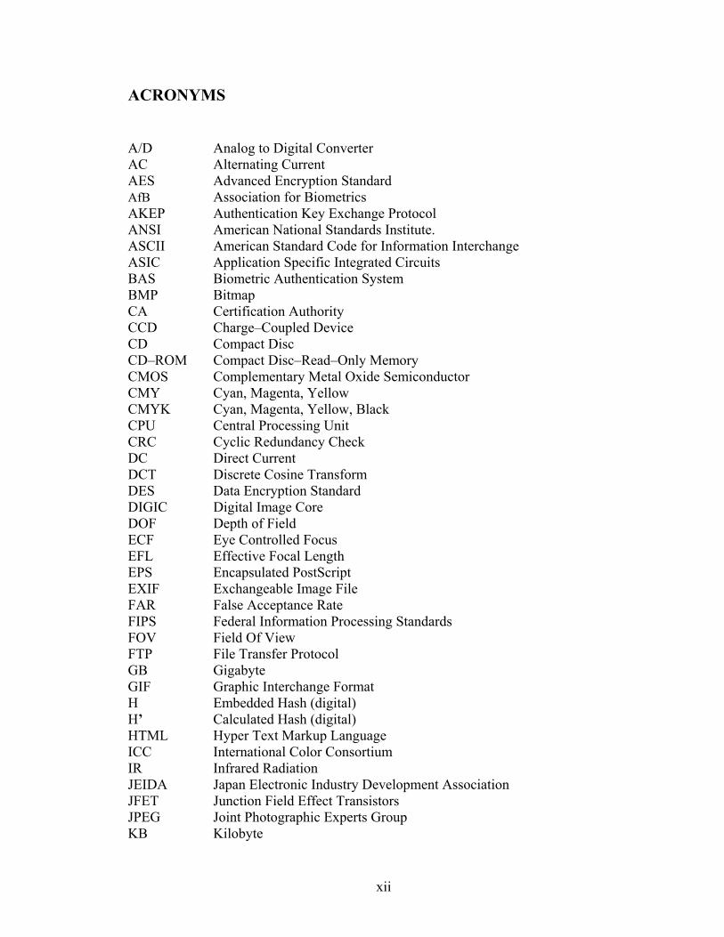
ACRONYMS
A/D Analog to Digital Converter AC Alternating Current AES Advanced Encryption Standard AfB Association for Biometrics AKEP Authentication Key Exchange Protocol ANSI American National Standards Institute. ASCII American Standard Code for Information Interchange ASIC Application Specific Integrated Circuits BAS Biometric Authentication System BMP Bitmap CA Certification Authority CCD Charge–Coupled Device CD Compact Disc CD–ROM Compact Disc–Read–Only Memory CMOS Complementary Metal Oxide Semiconductor CMY Cyan, Magenta, Yellow CMYK Cyan, Magenta, Yellow, Black CPU Central Processing Unit CRC Cyclic Redundancy Check DC Direct Current DCT Discrete Cosine Transform DES Data Encryption Standard DIGIC Digital Image Core DOF Depth of Field ECF Eye Controlled Focus EFL Effective Focal Length EPS Encapsulated PostScript EXIF Exchangeable Image File FAR False Acceptance Rate FIPS Federal Information Processing Standards FOV Field Of View FTP File Transfer Protocol GB Gigabyte GIF Graphic Interchange Format H Embedded Hash (digital) H’ Calculated Hash (digital) HTML Hyper Text Markup Language ICC International Color Consortium IR Infrared Radiation JEIDA Japan Electronic Industry Development Association JFET Junction Field Effect Transistors JPEG Joint Photographic Experts Group KB Kilobyte
xii

LAN Local Area Network LCD Liquid Crystal Display LED Light–Emitting Diode SB Least Significant Bit MA, (ma) Milliamphere MAA Message Authenticator Algorithm MAC Message Authentication Code MB Megabyte MD5 Message Digest 5 MP Megapixel MSB Most Significant Bit NIR Near Infrared NIST National Institute of Standards and Technology PC Personal Computer PCMCIA Personal Computer Memory Card International Association PNG Portable Network Graphics POTS Plain Old Telephone Service PRNG Pseudo Random Number Generator RAM Random Access Memory RGB Red, Green, and Blue ROM Read Only Memory RSA Data Security (Inc.) Algorithm (Initials of the 3 co–developers) SDC Secure Digital Camera SOP Standard Operating Procedures SSD Solid State Disk TIFF Tagged Image File Format USB Universal Serial Bus V Voltage or Volts VAC Volts (of) Alternating Current VDC Volts (of) Direct Current VGA Video Graphics Array VLSI Very Large Scale Integration (Electronic circuit chip) WORM Write Once, Read Many WWW World Wide Web WYSIWYG What You See Is What You Get
xiii

NOTATIONAL CONVENTIONS
ai , ao Angular half field of view in infinite conjugate systems.
D Distance between two elements.
F Effective focal length of the entire lens system.
F/# F/# is the lens’ ability to focus light.
Fi , Fo Focal length of the lens closest to the image and object, respectively.
Hi , Ho Image and object height, respectively. This represents HALF of the actual full
image and object size. In afocal systems, this represents half of the full beam
waist.
I , O Image and object distance measured from the lens closest to the image and
object respectively. M Magnification is the system’s ability to produce an enlarged/reduced image or
projection of an object.
q FULL angle of the cone of light accepted or emitted by a lens system (closely
linked to numerical aperture).
TP Throughput is the system’s ability to transfer light.
Superscripts Superscripts are used as indicate by the symbol or text below:
( )♥ A references a footnote at end of the page.
( )ii A sequentially numbered bibliography reference.
{ }{Appendix X } A cross–linked reference, used to further describe a new or uncommon
term not previously mentioned. It could be a cross–link to a Glossary
term, Bookmark, Section, Page number, etc.
Other: [ ] A cross–link to a Figure or Table, in this Dissertation i.e. [Figure 2.1]
xiv
1. Introduction
1.1. Motivation and Background
According to Blond’s Evidence iii, photographic evidence can be authenticated by
two methods, depending on the type of imagery. The traditional method is to consider
images as “illustrative of a witness testimony”. Given the advances in imaging
technology, many jurisdictions have adopted an alternative method based upon the silent
witness theory. This states that photographic evidence “speaks for itself” and is thus
admissible through testimony that establishes how it was produced.
In today’s world, not only is the general public rapidly replacing classical analog
cameras (film) with digital cameras, law enforcement agencies are doing so as well.
Increasingly, agencies are relying on digital photography to preserve a visual record of
crime scenes, physical evidence, and victim’s injuries. This is quite understandable
because a digital camera image gives the photographer immediate visual feedback of
each picture taken. Digital images can be readily shared via computer networks and
conveniently processed for queries in databases. In addition, properly stored digital
images do not age or degrade with usage. On the other hand, thanks to powerful editing
programs, it is very easy even for an amateur to maliciously modify digital media and
create “perfect” forgeries. An example of an illegitimate forensic application is the
“burning in ”of O. J. Simpson’s mug shot to make the stubble on his face appear darker,
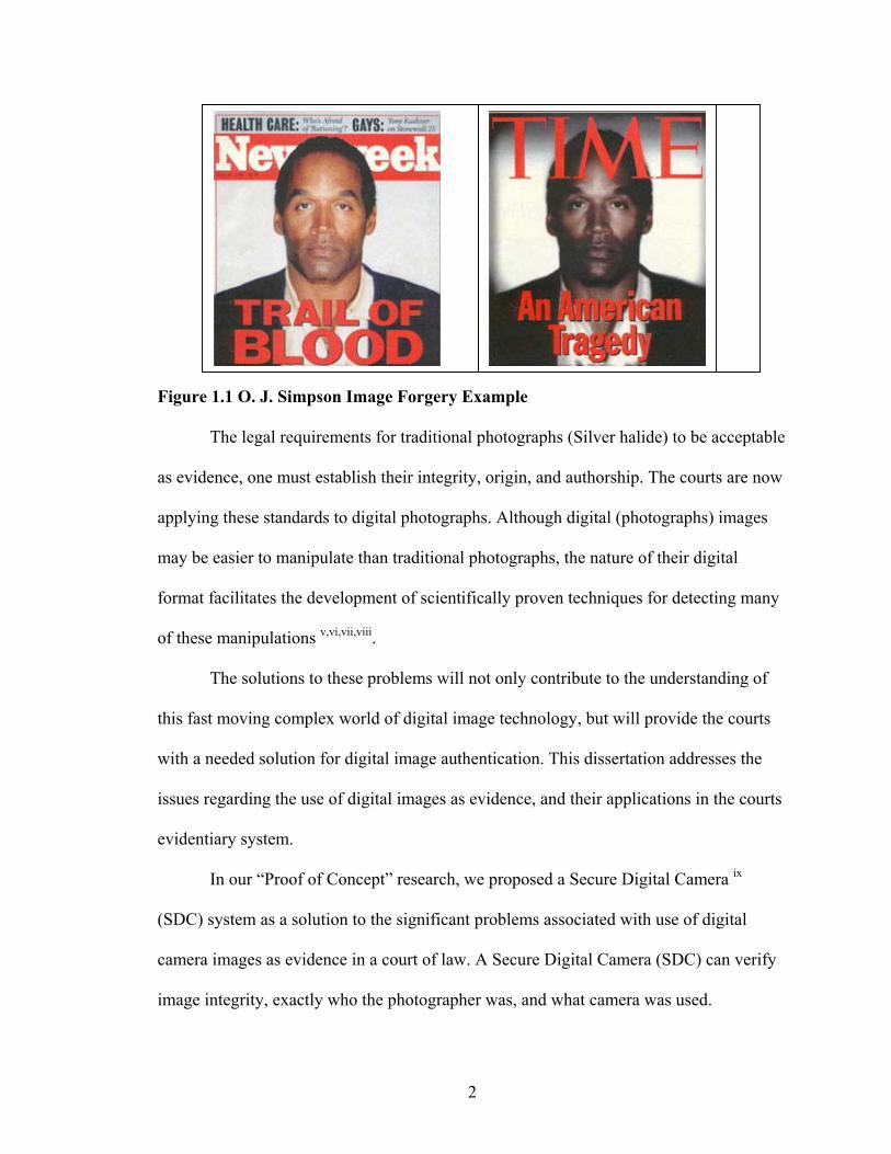
as shown in [Figure 1.1]. This is a deliberate effort to appeal to a viewer’s prejudice iv.
1
Figure
as evid
applyin
may be
format
of thes
this fas
with a
issues r
eviden
(SDC)
camera
image
1.1 O. J. Simpson Image Forgery Ex
The legal requirements for traditional p
ence, one must establish their integrity,
g these standards to digital photograph
easier to manipulate than traditional ph
facilitates the development of scientific
e manipulations v,vi,vii,viii.
The solutions to these problems will no
t moving complex world of digital imag
needed solution for digital image authen
egarding the use of digital images as ev
tiary system.
In our “Proof of Concept” research, we
system as a solution to the significant p
images as evidence in a court of law. A
integrity, exactly who the photographer
2
ample
hotographs (Silver halide) to be acceptable
origin, and authorship. The courts are now
s. Although digital (photographs) images
otographs, the nature of their digital
ally proven techniques for detecting many
t only contribute to the understanding of
e technology, but will provide the courts
tication. This dissertation addresses the
idence, and their applications in the courts
proposed a Secure Digital Camera ix
roblems associated with use of digital
Secure Digital Camera (SDC) can verify
was, and what camera was used.

Forensic tools that help verify the integrity, establish the origin, and authenticate a
digital image are thus very essential to the forensic examiner. These tools may prove to
have additional benefits, such as decreasing the possibility for human error, in the chain
of custody process. These forensic tools can prove to be vital whenever questions of
digital image integrity are raised.
Chain of custody♥ can be one of the most difficult issues faced by the forensic
professional trying to introduce a digital image as evidence in a criminal case.
1.2. Scope and Contributions
1.2.1. Scope
The work presented in this dissertation addresses the evidentiary problems
associated with the integrity, verification, and authentication of digital images in a court
of law. We offer a unique, first of its kind biometric authentication solution using our
secure digital camera. In the context of lossless authentication watermarking, we address
biometric watermarking, and detail the various techniques and technologies that were
involved.
1.2.2. Contributions
The particular contributions of this dissertation are as follows:
• Identified, detailed, and summarized the significant problems currently associated
with the use of digital images as evidence in a court. No system currently exists
that can verify the integrity, origin, and authorship of digital images.
• Proposed the first of its kind, Biometric Authentication System (BAS), for a
Secure Digital Camera (SDC), as a solution to these evidentiary issues.
♥ Chain of Custody: A process used to maintain and document the chronological history of the evidence.
3
• Designed and developed an iris capture system for iris recognition, that is located
inside of a standard camera viewfinder.
• Tested and explored the capacity vs. image quality issues associated with the
lossless data embedding technique implemented in our SDC, using the algorithms
developed by Fridrich, et al xxix.
• Designed and developed a working bench top prototype of a secure digital camera
system, using a novel approach, based on lossless watermarks for digital images
with a bioforensic identifier.
1.3. SDC Basic Design Concept Overview
The overall concept of a secure digital camera is to offer a solution to the
problems associated with the chain of custody for digital images presented to the court.
The SDC system consists of a secure digital camera that contains a unique fragile
watermarking chip, and a secret hard–wired embedding key inside of it. This
watermarking chip securely, losslessly, and invisibly embeds the photographer’s JPEG
compressed iris image, the hash of the scene image, date, time, and other camera/picture
information into the image of the scene photographed. This watermarked image is then
stored on the camera’s memory card for off line extraction and verification using the
secret camera key as diagramed in [Figure 1.2].
The problem of authorship is solved by the using the iris as a biometric identifier
of the photographer. Image integrity is guaranteed by the use of secure cryptographic
hashes (e.g., MD5) that detect any image modification. The secret camera ID key
identifies the exact camera used. Once authenticated, the SDC image is transferred to a
read only memory (ROM) type of archival storage system, such as a CD–ROM.
4

F
a
e
c
a
a
d
igure 1.2 Overall SDC Concept Block Diagram
1.3.1. The Internal Camera Design Concept
[Figure 1.3] illustrates our basic concept of how a secure digital camera
utomatically captures a digital image of the human iris, through the viewfinder with
very digital photograph taken.
This iris image is then JPEG compressed and combined with a hard–wired secret
amera identification key, the hash of the original scene image being photographed, and
dditional digital camera specifics, e.g. a time stamp. The result is a digital bioforensic
uthentication signature losslessly embedded by the watermarking chip, inside the secure
igital camera.
5

F
a
igure 1.3 Internal Camera Concept – Block Diagram
1.4. Prior Art
1.4.1. Digital Watermarking Cameras
Epson:
The following are the Epson cameras that have watermarking capabilities. They
re all discontinued camera models, as is the corresponding IAS software:
• Epson PhotoPC 700/750Z (1.2Mp)
• Epson PhotoPC 800/800Z (2.1Mp)
• Epson PhotoPC 3000Z (3.1Mp)
6

Epson uses a system called the “image authentication system”(IAS). The user
must purchase the software as an option and then upload it to the camera from a personal
computer. Once the IAS is installed in the camera, it will transparently add a digital
watermark (encrypted fingerprint) to each image captured. This still allows viewing of
images using any software that can read JPEGs, but the IAS software can verify the
authenticity of images. It can also detect any tampering, even if a single pixel has been
changed.
While not likely to be an essential feature for most users, it has clear forensic
benefits in many applications. If the camera is opened, the IAS system must be installed
again. The offline software allows one to verify the image integrity, as well as show the
areas that have been modified on a personal computer.
Kodak:
The following are the Kodak cameras that have watermarking capabilities. They
are all discontinued camera models:
• Kodak DC–200 (0.9Mp)
• Kodak DC–260 (1.3Mp)
• Kodak DC–290 (2.1Mp)
The Kodak DC–290 was the only camera Kodak made with digital watermarking
capabilities built in. It is also discontinued from manufacturing. The watermark settings
allow one to place any or all of the following watermarking options: date, time, text, or
logo visibly into the pictures. One can also select the watermarks characteristics, such as
left and top offset in picture, transparency level, text color, and background color as
shown in [
7

Figure 1.4].
Figure 1.4 Kodak Watermarked Image
The main difference between the Epson and the Kodak cameras is that the Epson
is better suited to camera image verification. It has an invisible watermark and can detect
a change in a single pixel.
The Kodak camera has a visible watermark. The watermark logo can be added
after the picture is taken with Kodak software. This has limited forensic use.
1.4.2. Digital Data Verification Cameras
Although the two previous cameras are obsolete, the strong need for law
enforcement, insurance, news and other agencies for a system capable of at least
verifying the originality of digital photographs has been recognized and addressed by the
Canon Corporation Inc., a camera manufacturing company.
8
Canon:
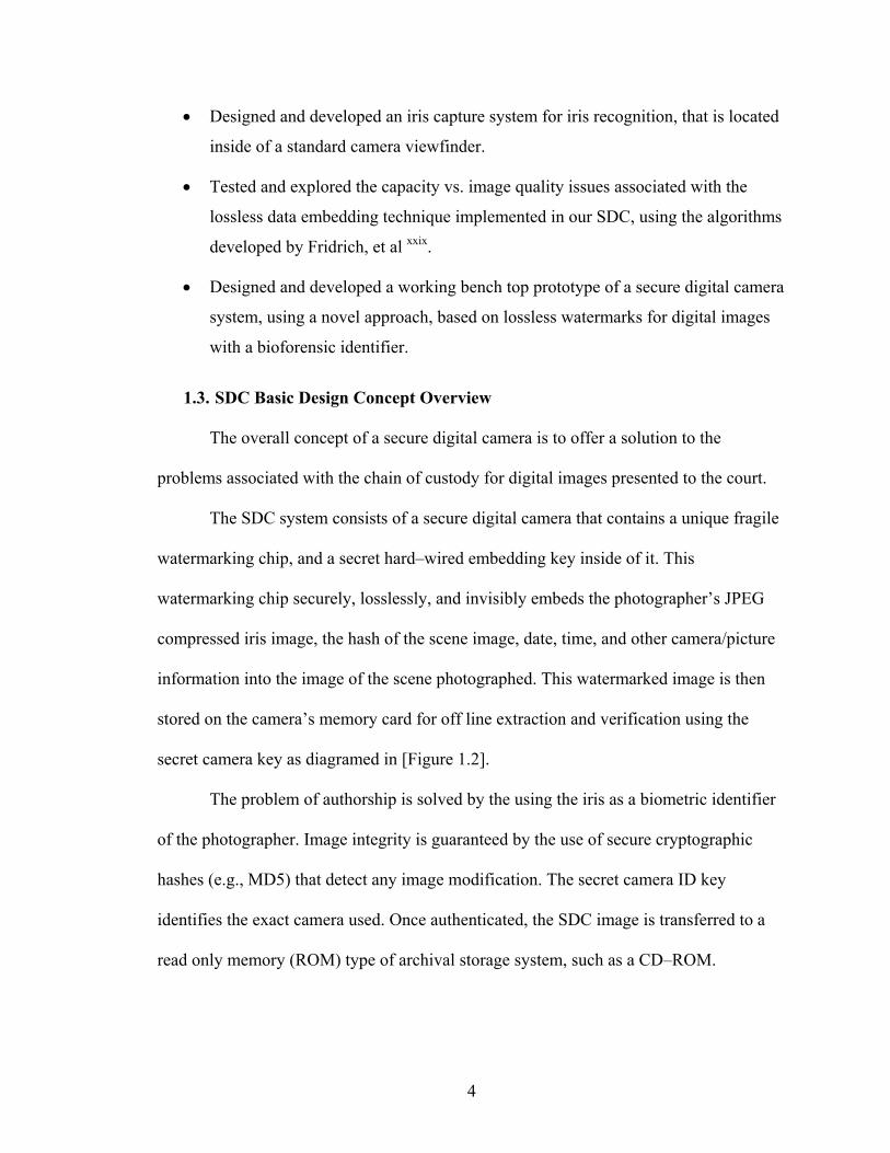
Canon now offers the data verification kit shown in Figure 1.5. This kit consists
of a dedicated SM (secure mobile) card reader/writer and verification software that
quickly scans image files from the following cameras:
• EOS–1D Mark II, & EOS–20D (8.2 Mp)
• EOS–1Ds (11.0 Mp)
• EOS–1Ds Mark II (17.2 Mp)
F
b
v
w
c
igure 1.5 Canon Data Verification Kit {Appendix B.}
When the personal function (# 31) on the above cameras is activated, a code
ased on the image contents is generated and appended to the image. When the image is
iewed, the data verification software determines the code for the image and compares it
ith the attached code. If the image contents have been manipulated in any way, the
odes will not match and the image cannot be verified as the original.
9

1.5. Digital Biometric Camera Patents
Searching the U.S. Patent Office database and other on–line resources, such as the
biometric consortium, we located only two patents that were close in design. However,
neither one had the unique features of our SDC. The following are the details for the two
patents and their abstracts:
1. Application Number: US2001000900370, as shown in [Figure 1.6].
Abstract: (Verbatim) An iris camera module includes an image pickup optical
system and a target optical system and the optical path is divided by a half mirror. An
image of an iris is picked up by an image pickup element of an image pickup section. The
iris image thus picked up is compared with a reference iris image stored in storage in
advance and the comparison result is output. The iris camera module has a configuration
fit for a compact design. The reference iris image as a reference for comparison is stored
in the storage of the comparison chip. It is thus difficult to falsify the reference iris image
thereby providing a high security.
Figure 1.6 Patent Application Number: US2001000900370
10

In the first referenced patent (US2001000900370), the only similarity to our SDC
is the viewfinder iris image system. The concept of this camera is for use as a security
camera. It does not allow unauthorized users to operate the camera based on a reference
iris image that was stored in advance. This not only limits the number of users, it does not
append or insert the iris image into the scene. This camera does not offer a solution to the
evidentiary problems of digital images.
2. Application Number: US20020080256A1: Digital camera apparatus with
biometric capability, as shown in [Figure 1.7].
Abstract: (Verbatim) A digital camera contains biometric capability to identify a
photographer, which is preferably provided by the camera’s own optical sensors. The
biometric feature is preferably the iris of a photographer's eye, which is recognized as
unique for each individual. The camera captures an image of an iris, abstracts a set of
distinguishing features, and matches this set to an on–board database. The iris image is
preferably captured when the photographer brings his eye in the vicinity of the camera's
viewing window, through a combination of mirrors, lenses, prisms, and the like. This
capability may be used to record the identity of a photographer with the image, as an
anti–theft or privacy device, or to personalize the camera settings.
Figure 1.7 Patent Application Number: US20020080256A1
11

In the second referenced patent (US20020080256A1), the only similarity to our
SDC is the viewfinder iris image system. The concept of this camera is as an anti–theft
deterrent, privacy device, or to personalize the camera settings. This camera performs the
feature extraction and matching of the iris image done on–board (within) the camera. The
on–board database is costly. It would reduce camera performance time, with current
technology, in addition to limiting the number of camera users.
Both of the referenced patents are conceptually similar, since they focus on
personal security issues of camera’s use. They both use on board recognition systems that
severely limit the number of users.
Unlike the SDC, neither patent offers a solution to the evidentiary problems
associated with the use of digital image as evidence.
1.6. Related Works
In this section, we refer to works concerned with iris recognition since, to our
knowledge, no one has attempted to losslessly embed the iris into a digital image. Most
of the existing papers deal with converting an acquired iris image into a suitable code that
can be easily manipulated. The iris recognition systems of Boles, Daugman, and Wildes,
are compared by author Lim, S., in the following abbreviated summary of an article in the
ETRI Journal x.
1.6.1. ETRI Journal Summary
As briefly stated in the ETRI Journal, Daugman xiv developed the feature
extraction process based on information from a set of 2–D Gabor filters. He generated a
256byte code by quantizing the local 2,048 bit phase vectors according to the outputs of
the real and imaginary parts of the filtered image. A test of statistical independence is
12

implemented by the simple Boolean Exclusive-OR operator (XOR) applied to the 2,048
bit phase vectors that encode any two iris patterns. The norms (|| ||) of the resultant
XOR'ed phase bit vectors and of the filtered (AND'ed mask) vectors are then measured in
order to compute a fractional Hamming Distance as the measure of the dissimilarity
between any two irises
On the contrary, the Wildes’ xi system made use of a Laplacian pyramid
constructed with four different resolution levels to generate iris code. It also exploited a
normalized correlation based on goodness–of match values and Fisher’s linear
discriminant for pattern matching. Both iris recognition systems make use of band pass
image decompositions to get multi–scale information.
Boles xii implemented the system operating the set of 1–D signals composed of
normalized iris signatures at a few intermediate resolution levels and obtaining the iris
representation of these signals via the zero crossing of the dyadic wavelet transform. It
made use of two dissimilarity functions to compare the new pattern with the reference
patterns.
Boles’ approaches have the advantage of processing 1–D iris signals rather than a
2–D image used by both Daugman and Wildes. They both proposed and implemented a
whole system for personal identification or verification, including the configuration of
image acquisition device. Boles’ only focused on the iris representation and matching
algorithm without an image acquisition module.
The ETRI paper identifies some of the problems that the author, Shin Young Lim,
experienced in his attempts to acquire a human iris image. Many similar problems had to
be considered when designing the SDC viewfinder capture (Acquisition) module.
13

Figu
For e
1.8],
Tabl
DW
Glawit
DatG
re 1.8 Failure Examples for Iris Recognition
xplanations of the types of errors (Numbers 1–9) below each iris image in Figure
refer to their tabulated failure analysis shown in [Table 1.1].
e 1.1 Failure Causes for Iris Recognition
Cause of Failure # of Data Ratio (%)(1) Occlusion by eyelids 178 31 (2) Inappropriate eye positioning 127 22 (3) Shadow of eyelids 121 21 (4) Noises with pupil 34 6 (5) Etc 115 20
ata ithout sses and h Lens
Total 575 100 (6) Noises of dirt on the glasses 49 37 (7) Reflection of glasses 28 21 (8) Shadow of the rim of glasses 20 15 (9) Etc 36 27
a With lasses
Total 133 100
14

In the ETRI experiments, the iris image was obtained at a distance of 200mm. Many
of the iris capture problems would be significantly reduced or eliminated in the SDC, due
to the close proximity of the iris to the camera’s viewfinder capture system.
1.7. Digital Images as Evidence
We believe that the legal concerns raised by digital images, as opposed to
traditional photographs, are not as different as one may believe. Currently, the courts
accept traditional photography as a process that is known to be a “trustworthy” one.
There are many similarities that exist between traditional and digital photographs.
For example, traditional cameras use photographic film to record an image using
light–sensitive collectors called silver halide. A digital camera records an image using
light–sensitive collectors called pixels. As light strikes the surface of the film, individual
particles of silver halide change chemically. As light strikes the surface of the digital
camera sensor, individual pixels change (Opto) electronically. The longer the exposure,
the greater is the change with both photographic film, and digital image sensors.
The accuracy and detail of traditional camera images are dependent upon the
resolution of the optical system used in the camera, as well as the film density (grain),
and physical size. The larger the film size is, the greater the image resolution will be. Just
as with traditional cameras, the accuracy and detail of digital camera images are
dependent upon the resolution of the cameras optical system, as well as the size of the
image sensor. The larger the physical size of the image sensor (In Mp), the greater the
image resolution will be. In general, the better the optics, the higher the light intensity,
and the larger the size of the film, or image sensor, the more accurate and detailed the
images will be with either technology.
15
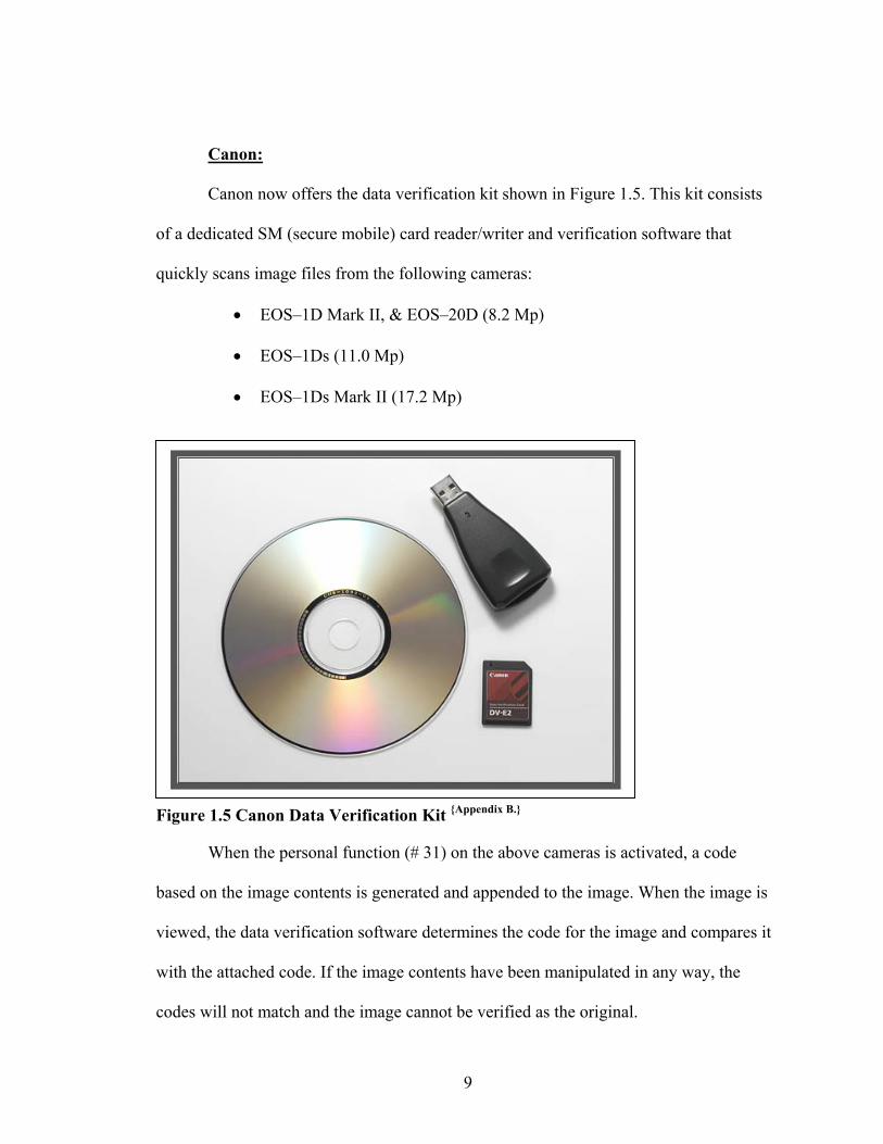
The actual process of capturing an image on photographic film, or digital image
sensor is more complex than our simplified explanation, but for the purposes of this
dissertation, it should be adequate to show the similarities between a typical digital image
and photographic film.
These similarities should be clear to anyone who has used a camera from
believing a digital camera image is the result of some novel scientific process. With
recent advances in digital camera sensor sizes and image processing technology, the
ability of photographic film to record an image more accurately is now being questioned.
The world has taken photographs for granted since the first daguerreotype was
presented on August 19, 1839 xiii. Digital images, on the other hand, still represent a
mystique when shown to the average citizen. The origin and validity of digital images are
looked upon with some suspicion. This is especially true when the image is introduced
into legal proceedings. Defense attorneys and judges tend to be distrustful of technology;
and jurors get easily confused by technical explanations.
1.7.1. Photographs as Evidence
The principal requirements to admit a photograph (digital or film–based) into
evidence are relevance and authentication. Unless the photograph is admitted by the
stipulation of both parties, the party attempting to admit the photograph into evidence
must be prepared to offer testimony that the photograph is an accurate representation of
the scene. This usually means someone must testify that the photograph accurately
portrays the scene as viewed by that witness.
Evidence that is merely illustrative of verbal testimony and carries no independent
probative value may be used as demonstrative evidence to aid a witness’ testimony or to
16
help counsel in opening or closing arguments. Demonstrative evidence has been an
effective courtroom tool; litigators have used chalkboards, maps, diagrams, photographs,
films, and videos to help the jury understand and remember witness testimony.
The Courts also recognize that “general admissibility” is not the sole admissibility
factor for scientific evidence; trial courts should also look to peer review and publication,
the known or potential rate of error (i.e. FAR) of the process or technique, and whether
the process or technique has been tested. ♥The Courts stress the importance of “testing”
[scientific techniques] to see if they can be “falsified” and mentioned “the criterion of the
scientific status of a theory is its falsifiability. This “testing” will be a requirement for our
SDC system to be a useful and accepted tool.
In addition to the methods of authentication listed in Rule 901(b), the common
law sets forth various authentication procedures. By examining common law
authentication tests for types of evidence similar in nature to digital images, focusing on
trends in the courts and the explanations for those trends, one might better judge the
nature of the authentication requirements to which digital images may be subjected.
From the extensive legal research we performed, it appears that the current
evidentiary system is not equipped to authenticate digital images. The SDC will help the
courts by eliminating the many obstacles that traditional photographs now face.
Despite the fact that digital images are a different media form than traditional
photographs, courts often use the same methods to authenticate digital images that they
use to authenticate traditional photographs.
♥ Quoting: Popper, K., Conjectures and Refutations, “The Growth of Scientific Knowledge”, 37 (5th ed. 1989).
17
2. Biometric Systems
Introduction
The term ‘Biometric’ is derived from the Greek words bio (life) and metric (the
measure of). ‘Biometrics’ can been defined as: “A pattern recognition system that
recognizes a person by determining the authenticity of a specific physiological and/or
behavioral characteristic possessed by that person.” The most commonly used form of
biometrics in use today is a fingerprint. Fingerprints are a good choice for biometric
identification because they possess two very important characteristics required for
biometric identification. The first characteristic is that fingerprints are unique for each
individual. The second characteristic is that fingerprints are permanent, since they do not
change over time. It is for these two reasons that fingerprints were the first legally
accepted biometric technique used for identification.
Biometric–based authentication applications include cell phones, computers,
transaction security (ATM), remote and local resource access, and web security.
Common physical biometric technologies include the following:
• Finger Print (dactylogram) Identification
• Hand or palm Geometry Identification
• Voice Recognition
• Signature Recognition
• Retina Identification
• Facial Recognition
• Iris Identification
18

2.1. Choosing a Biometric Identifier
Of the many biometric technologies available, only the following two met the
physical size constraints of our (SDC) camera, and possessed the biometric
characteristics our SDC design required; uniqueness, and permanency:
• Fingerprint Patterns: The analysis of an individual’s unique fingerprints.
• Iris: The analysis of the colored ring that surrounds the eye’s pupil
1. Uniqueness: Is the characteristic that a biometric identifier is
unique for each individual.
2. Permanency: Is the characteristic that a biometric identifier
remains permanent, since it does not change over time (I.e. a
person’s face does change over time).
The fingerprint identification systems currently under testing were proving to be
difficult to use due to moisture problems. A glove would hamper its use as well.
We considered many variables when we compared the two technologies. They
included, but were not limited to implementation and integration time and costs, user
friendliness, reliability, and legal acceptability. The iris was selected to be the biometric
identifier that the SDC watermarking chip losslessly embeds into the cover image.
2.2. Anatomy of the Eye
The very front of the eye is essentially made up of two parts: the sclera, or
“white” of the eye, and cornea. The sclera consists of closely interwoven fibers and
covers the entire surface of the eye, except for a small section in the back, where the optic
nerve leaves the eye, and a small section directly in front and centered, known as the
cornea as shown in [Figure 2.1].
19
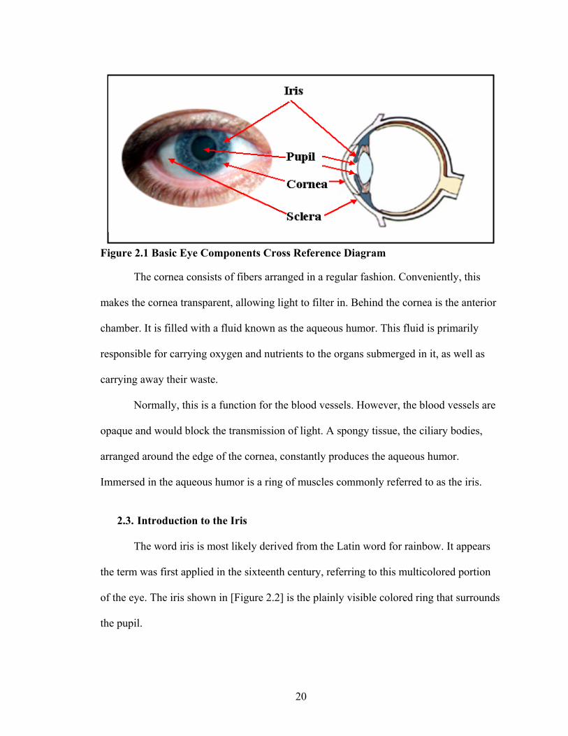
Figure 2.1 Basic Eye Components Cross Reference Diagram
The cornea consists of fibers arranged in a regular fashion. Conveniently, this
makes the cornea transparent, allowing light to filter in. Behind the cornea is the anterior
chamber. It is filled with a fluid known as the aqueous humor. This fluid is primarily
responsible for carrying oxygen and nutrients to the organs submerged in it, as well as
carrying away their waste.
Normally, this is a function for the blood vessels. However, the blood vessels are
opaque and would block the transmission of light. A spongy tissue, the ciliary bodies,
arranged around the edge of the cornea, constantly produces the aqueous humor.
Immersed in the aqueous humor is a ring of muscles commonly referred to as the iris.
2.3. Introduction to the Iris
The word iris is most likely derived from the Latin word for rainbow. It appears
the term was first applied in the sixteenth century, referring to this multicolored portion
of the eye. The iris shown in [Figure 2.2] is the plainly visible colored ring that surrounds
the pupil.
20

Figure 2.2 Key Eye Components for Iris Recognition Systems
The function of the iris is to control the amount of light entering through the
pupil. The sphincter and the dilator muscles adjust the size of the pupil accordingly to the
amount of light entering the eye. The average diameter of the iris is 12mm xiv, and the
pupil size can vary from 10% to 80% of the iris diameter.
The pupil may not be exactly circular in shape. The centers of the iris and pupil
are different, and can differ from each other of about 20% xv.
2.4. The Individuality of the Iris
No two irises are alike. There is no detailed correlation between the iris patterns
of even identical twins or the right and left eye of an individual. The amount of
information that can be measured in a single iris is much greater than fingerprints. It is
extremely difficult to surgically tamper the texture of the iris. Further, it is rather easy to
detect artificial irises xvi (e.g., designer contact lenses). Developmental biology further
suggests that, while the general structure of the iris is genetically determined, the
21

particular aspects of its details are dependent upon circumstance, like the conditions in
the embryonic precursor to the iris. Developmental biology also supports the lack of
variance through life idea. The human iris begins to form during the third month of
gestation. The structures creating its distinctive pattern are complete by the eighth month
of gestation. But pigmentation continues into the first years after birth.
The only marked exceptions are the pigmentation, which does not fully mature
until adolescence, and the size of the pupil, which is also not fully determined until
puberty. However, once out of the teenage years, a person’s iris variations will likely
remain the same for the rest of his/her life (thus the enormous interest in utilizing iris
variation in a biometric system).
2.5. Iris Functionality
The actual physical functionality of the iris is quite remarkable. It is often
compared to the diaphragm (Opening for light to pass) of a camera, as it shares some
characteristics. A typical iris has an f–number around f/2 or f/3, ideal for maximum
exposure to light. An f-number is the diameter of a camera lens diaphragm aperture in
terms of the effective focal length of the lens. For example, f/11 represents a diaphragm
aperture diameter that is one-eleventh of the focal length (or the focal length is 11 times
the aperture) The iris can change the amount of light coming into the eye in about a fifth
of a second, but the reduction amount is minuscule – less than a factor of 20 (about
another f–stop). This obviously points out that the iris is not responsible for control of
light intensity, for this is primarily the job of the rods and cones in the back of the retina.
However, like changing the f–stop on a camera, the iris can seriously reduce aberrations,
especially in bright conditions, and increase depth of field {DOF}.
22

When using a manual camera in bright light situations, you decrease the (iris size)
f–stop, for proper exposure. The human eye functions in a manner by decreasing the
pupil size to allow less light in, which makes it easier to identify incoming images. When
focusing in on close objects, such as a book, computer monitor, or watch, the iris stops
down to increase the depth of field.
This is also the case in photography, where decreasing the f–stop (Opening for
light), sharpens the resulting image. During low light levels, however, the iris serves the
opposite purpose. Much like one would do for night photography, increasing the f–stop to
let in more light, the iris opens as much as possible to allow the faintest light to enter the
eye. Once the rods have adjusted to current light levels, a small amount of light is all they
need to perform basic image detection.
Fig
ma
cam
ray
the
eye
ure 2.3 Camera and Eye Comparisons
To summarize in a simple manner, the individual components of the eye work in a
nner similar to a camera as shown in [Figure 2.3]. The cornea’s function is similar to a
era lens cover. The eye's main focusing element, the cornea, takes widely diverging
s of light and bends them through the pupil, the dark, round opening in the center of
colored iris. The iris and pupil act like the aperture of a camera. The function of the
lens, like the camera lens, is to focus light to the back of the eye.
23

The very back of the eye is lined with a layer called the retina. The retina acts
very much like the film of the camera, or the image sensor in a digital camera. The retina
is a membrane containing photoreceptor nerve cells that lines the inside back wall of the
eye. The photoreceptor nerve cells of the retina change the light rays into electrical
impulses. The optic nerve transmits these electrical impulses to the brain, where an image
is perceived. The macula, the center 10% of the retina, is responsible for sharp vision,
such as when reading. The peripheral retina is responsible for the peripheral vision.
2.6. Iris Recognition – The Current Technology
Daugman’s (University of Cambridge) research patents on iris recognition form
the basis of this section (Iridian Technologies, Inc. of Moorestown, NJ, formerly IrisScan
Corporation). This section (2.6.) summarizes the iris recognition information obtained
from Daugman’s web page. {Appendix B.}.
2.6.1. Iris Characteristics
Iris recognition is based on visible (via regular and/or infrared light) qualities of
the iris. Expressed simply, iris recognition technology converts these visible
characteristics into a 512 byte IrisCode®, a template stored for future verification
attempts. 512 bytes is a compact size for a biometric template, but the quantity of
information derived from the iris is massive.
From the 11mm diameter iris, Daugman’s algorithms provide 3.4 bits of data per
square mm. This density of information is such that each iris can be said to have 266
unique “spots”, as opposed to 13–60 for traditional biometric technologies (I.e.
fingerprint). Daugman concludes that 173 “independent binary degrees–of–freedom” can
be extracted from his algorithm–an exceptionally large number for a biometric.
24

2.6.2. The Algorithms
The first step is location of the iris by a dedicated camera no more than 3 feet
from the eye as shown in [Figure 2.4]. After the camera situates the eye, the algorithm
narrows in from the right and left of the iris to locate its outer edge. This horizontal
approach accounts for obstruction caused by the eyelids. It simultaneously locates the
inner edge of the iris (at the pupil), excluding the lower 90 degrees because of inherent
moisture and lighting issues.
F
i
u
(
o
igure 2.4 Iris Area Algorithm
The monochrome camera uses both visible and infrared light, the latter of which
s located in the 700–900nm range. Upon location of the iris, as seen above, an algorithm
ses 2–D Gabor wavelets to filter and map segments of the iris into hundreds of vectors
known here as phasors). Not the entire iris is used, a portion of the top, as well as 45deg.
f the bottom, are unused to account for eyelids and camera–light reflections. For future
25
identification, the database will not be comparing images of irises, but rather hexadecimal
representations of data returned by wavelet filtering and mapping.
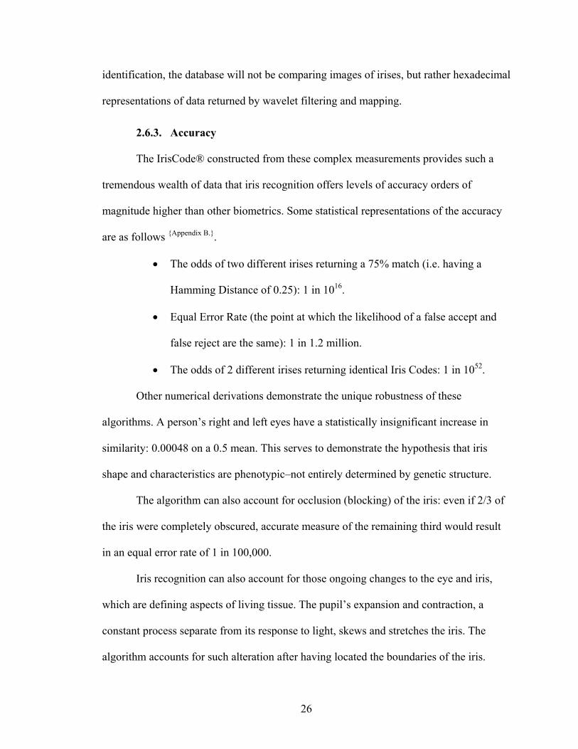
2.6.3. Accuracy
The IrisCode® constructed from these complex measurements provides such a
tremendous wealth of data that iris recognition offers levels of accuracy orders of
magnitude higher than other biometrics. Some statistical representations of the accuracy
are as follows {Appendix B.}.
• The odds of two different irises returning a 75% match (i.e. having a
Hamming Distance of 0.25): 1 in 1016.
• Equal Error Rate (the point at which the likelihood of a false accept and
false reject are the same): 1 in 1.2 million.
• The odds of 2 different irises returning identical Iris Codes: 1 in 1052.
Other numerical derivations demonstrate the unique robustness of these
algorithms. A person’s right and left eyes have a statistically insignificant increase in
similarity: 0.00048 on a 0.5 mean. This serves to demonstrate the hypothesis that iris
shape and characteristics are phenotypic–not entirely determined by genetic structure.
The algorithm can also account for occlusion (blocking) of the iris: even if 2/3 of
the iris were completely obscured, accurate measure of the remaining third would result
in an equal error rate of 1 in 100,000.
Iris recognition can also account for those ongoing changes to the eye and iris,
which are defining aspects of living tissue. The pupil’s expansion and contraction, a
constant process separate from its response to light, skews and stretches the iris. The
algorithm accounts for such alteration after having located the boundaries of the iris.
26

Daugman draws the analogy to a “homogenous rubber sheet” which, despite its
distortion, retains certain consistent qualities. A question asked of all biometrics is their
ability to determine fraudulent samples. Iris recognition can account for this in several
ways: the detection of papillary (pupil) changes, reflections from the cornea, detection of
contact lenses atop the cornea, and use of infrared illumination to determine the state of
the sample eye tissue.
2.6.4. Advantages and Disadvantages of Iris for Identification:
Advantages of the Iris for Identification:
• Highly protected, internal organ of the eye
• Externally visible; patterns imaged from a distance
• Iris patterns possess a high degree of randomness
o Variability: 244 degrees–of–freedom
o Entropy: 3.2 bits per square–millimeter
o Uniqueness: set by combinatorial complexity
• Changing pupil size confirms natural physiology
• Pre–natal morphogenesis (7th month of gestation)
• Limited genetic penetrance of iris patterns
• Patterns apparently stable throughout life
• Encoding and decision–making are tractable
Disadvantages of the Iris for Identification :
• Small target (1 cm) to acquire from a distance (1 m)
• Moving target ...within another... on yet another
• Located behind a curved, wet, reflecting surface
• Obscured by eyelashes, lenses, reflections
• Partially occluded by eyelids, often drooping
• Deforms non–elastically as pupil changes size
• Illumination should not be visible or bright.
• Some negative (Orwellian) connotations.
27

2.7. Electromagnetic Spectrum
The electromagnetic spectrum covers the total range of possible wavelengths of
photons from the shortest “gamma rays” through x–rays, the ultraviolet, the visible,
infrared, and microwave to the longest “radio waves” [Figure 2.5]
n
s
a
m
i
s
Figure 2.5 The Electromagnetic Spectrum
2.8. Light
The main characterization of light is by its wavelength, most often specified in
anometers (nm). We can also define a frequency for each wavelength by dividing the
peed of light by the wavelength.
The range of light wavelengths we see are called the “visible spectrum”. It covers
range from about 400nm to 555nm to 750nm (violet to green to red). The human eye is
ost sensitive to light at a wavelength of 555nm, which is equal to 5.4 × 10¹⁴ Hz.
The range just above the visible, the near infrared (NIR), is most commonly used
n infrared (IR) remote controls and is the dominant wavelength in the night sky
pectrum.
28

In the SDC, the NIR LED’s (850nm) utilize this non–visible feature to illuminate
the iris. This feature provides for a less intrusive biometric (iris) acquisition system.
Figure
2.6 Eye Sensitivity and Visible Light Wavelengths
29
3. Digital Data Authentication
Introduction
The concepts behind data authentication are well stated in the following definition
on the Cisco web site’s {Appendix B.} glossary:
It states that data authentication includes two concepts:
1. Data integrity (verify that data has not been altered).
2. Data origin authentication (verify that the data was actually sent by the
claimed sender).
Data authentication can refer either to integrity alone or to both of these concepts
(although data origin authentication is dependent upon data integrity).
We begin with the technical history of digital data verification by describing the
original concepts, and specific terms, or techniques required for a thorough understanding
of data authentication. Data verification began with the use of digital signatures.
3.1. Digital Signatures for Verifying Data Authenticity
Historically, digital data authenticity was verified by the use of digital signatures.
The integrity and authenticity of digital data relied upon the use of digital signatures xvii.
A digital signature is binary information (Digital) that is appended to a (digital) message
to assure the recipient of the authenticity and integrity of the message.
Digital signatures use public–key cryptography {Cryptography}, in which the signer
has a private key used for creating signatures and a public key used for signature
30
verification. Digital signatures and their cryptographic properties have been well studied.
A number of algorithms, such as RSA {RSA algorithm } and DSA {DSA algorithm}, are used
extensively in the various authentication techniques xvii. A hash function is used to create
and verify a digital signature. A hash function is an algorithm which creates a standard
length digital representation (Fingerprint) of the document called a hash value. Hashing
algorithms are “one–way” since you are able to create a hash from a document, but you
are unable to recreate the document from a hash. A hash is usually smaller than the
document, but it is not an encryption of the document. The main disadvantage of a digital
signature over a digital watermark is a digital signature is appended in the header of an
image file and it may be easily stripped off, such as when opening a document, or when
saving it under a different format.
3.1.1. Digital Watermarking
Introduction
A digital watermark is best described by comparing it to a traditional watermark.
Traditional watermarks are added to some types of paper to offer proof of authenticity.
They are imperceptible, except when the paper is held up to a light for inspection.
Similarly, digital watermarks are added to still images in a way that can be seen by a
computer but is imperceptible to the human eye under normal observation conditions.
This is possible by taking advantage of imperfections in the human senses, such as
masking, and other properties of the human visual systemxviii, xix.
3.2. Watermark Classification and Terms for SDC
Watermarks can be visible or invisible depending on their application and their
relationship to the cover media.
31

Visible watermarks are designed to convey visual message indicating proof of
ownership such as a company logo. Visible watermarks should not detract from the
content of the digital data.
Invisible watermarks are imperceptible/inaudible under normal
viewing/listening conditions. The existence of such a watermark is determined only by
using a watermark extraction or detection algorithm.
A further classification of watermarks is into fragile, semi–fragile, and robust.
Fragile watermarks detect every possible modification of the image with high
certainty. Fragile watermarks are usually realized by embedding a cryptographic hash
into the image xx xxviii, xxx .
Semi–fragile watermarks are supposed to be insensitive to “allowed”
manipulations, such as lossy compression or small amount of common processing, but
react sensitively to malicious content–changing manipulations, such as adding or
removing objects xxi, xxii.
Robust watermarks are detectable even after attempts are made to remove them.
Robust hashes xxiii, and robust watermarks xxiv, are employed to facilitate content
authentication of digital images.
It is doubtful a universal watermarking technique will ever exist that can satisfy
all the requirements of all applications. Watermarking systems are designed within the
context of their application, which in turn dictate the applicable watermarking
technique(s). The use of the terms, “digital watermarking”, “data embedding”, and “data
hiding”, and are often interchanged. For example, the term data hiding only implies that
the embedded information is imperceptible to a human observer, as opposed to a
32
reference to steganography or covert communications, where statistical undetectability is
an additional requirement. A watermarking system consists of two basic components, a
watermark embedding system, and a watermark extraction (Authentication) system.
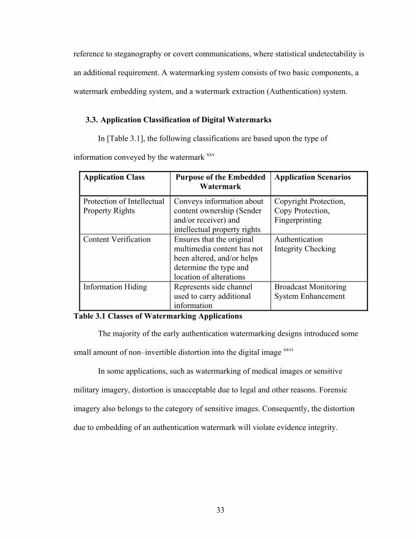
3.3. Application Classification of Digital Watermarks
In [Table 3.1], the following classifications are based upon the type of
information conveyed by the watermark xxv
Application Class Purpose of the Embedded Watermark
Application Scenarios
Protection of Intellectual Property Rights
Conveys information about content ownership (Sender and/or receiver) and intellectual property rights
Copyright Protection, Copy Protection, Fingerprinting
Content Verification Ensures that the original multimedia content has not been altered, and/or helps determine the type and location of alterations
Authentication Integrity Checking
Information Hiding Represents side channel used to carry additional information
Broadcast Monitoring System Enhancement
Table 3.1 Classes of Watermarking Applications
The majority of the early authentication watermarking designs introduced some
small amount of non–invertible distortion into the digital image xxvi
In some applications, such as watermarking of medical images or sensitive
military imagery, distortion is unacceptable due to legal and other reasons. Forensic
imagery also belongs to the category of sensitive images. Consequently, the distortion
due to embedding of an authentication watermark will violate evidence integrity.
33
3.4. Authentication Watermarks
Authentication watermarks are broken down into two categories, fragile and
semi–fragile watermarks. Since semi–fragile watermarks allow authorized image
modifications, we will restrict our attention to fragile watermarks, which address the
issues of image authentification and verification.
A fragile watermarking system consists of the two common components of all
watermarking systems, a watermark embedding system and a watermark extraction
system.
Authentication watermarks embedded by a watermarking chip inside the digital
video and still cameras have been proposed in the past xxvii, xxviii. However, because the
authentication process invariably modifies the image, the legal problems associated with
watermarking prevented the spread of watermarking technology. To overcome this
problem of authentication watermarks, the novel scheme of “lossless watermarking” was
proposed xxix. In lossless watermarking, the embedding distortion is completely removed
from the watermarked image and thus one can obtain the unmodified original image
3.5. Biometric Watermarking
Biometric Watermarking is the process that creates a link between a human
subject and the digital media by embedding biometric information into the digital object
as shown in [Figure 3.1].
Using a secret key, the SDC combines a fragile watermarking scheme with a
biometric watermark (The iris) to produce a watermarked image inside of the camera.
34

Fig
Secret Key
em
ure 3.1 SDC Biometric Watermarking Scheme Block Diagram
(Digital Image)Carrier
Fragile Watermark Embedding
Scheme
BiometricWatermark
(Digital)
(Biometrically)Watermarked
Carrier
Within the limited context of image authentication, and the lossless watermark–
bedding scheme of our SDC, we can define lossless biometric watermarking as:
“The p
authentication
introducing vis
inserted informa
Lossless Biometric Watermarking
rocess of losslessly embedding biometric
information into the cover image, without
ible artifacts, and subsequently utilizing the
tion to validate the authenticity and integrity
of the cover image.”
35

3.6. JPEG
Introduction
The main goal of this dissertation is to prove the feasibility of our proposed
concept. Therefore, we did not implement the lossless watermark embedding technique in
hardware. Instead, we simulated the Watermarking Chip inside of the camera using a
software implementation of a lossless data embedding technique for JPEG images
described in xxix, the paper that is the basis of this section.
In this section, we describe two watermarking techniques for JPEG files that
embed a MAC (Message Authentication Code){MAC} in quantized DCT coefficients in a
lossless manner so that anyone who possesses the authentication key can revert to the
exact copy of the original image before authentication occurred. The first technique
described in section {3.7.1}, is based on lossless compression of biased bit–streams derived
from the quantized coefficients. In {3.7.4}, we introduce another very simple technique in
which one entry of the quantization table is modified to obtain a completely biased
sequence of coefficients that can be readily used for lossless data embedding and
authentication. A summary is given in Section {3.7.5}.
3.6.1. JPEG Concepts
We will begin with a definition, and then a description of the JPEG compression
process.
JPEG stands for Joint Photographic Experts Group, the original name of the
committee that wrote the standard. JPEG is a standardized image compression algorithm.
36

JPEG is designed for compressing either full–color or gray–scale images
consisting of natural, real world scenes. JPEG is "lossy", meaning that the decompressed
image isn't the same as the uncompressed image. A photograph actually contains
considerable information that the human visual system cannot detect and that can be
safely discarded.
There are lossless image compression algorithms, but JPEG achieves much
greater compression than is possible with lossless methods. JPEG is designed to exploit
known limitations of the human visual system, notably the fact that small color changes
are perceived less accurately than small changes in brightness. A useful property of JPEG
is that adjusting compression parameters can vary the degree of lossiness. That allows the
trade off of the file size, against the output image quality.
Since the majority of JPEG files use the Baseline Sequential compression
technique as a standard, this dissertation will address JPEG compression within that
context. The lossless embedding method as part of the JPEG compression is illustrated in
[Figure 3.2], and a description given in section {3.7.4}.
Figure 3.2 Lossless JPEG Embedding Method 2, Q (i,j)→ Q (I,j)/2
37

3.6.2. The JPEG Encoder Steps:
1) The linear transformation in color space: [R G B] –> [Y Cb Cr]
(R, G, B are 8–bit unsigned values) The following is the formula for the
transformation:
Y = 0.2990 × R + 0.5870 × G + 0.114 × B (Luminance)
Cb = – 0.1687 × R – 0.3313 × G + 0.5 × B + 128 (Chrominance)
Cr = 0.5 × R – 0.4187 × G – 0.0813 × B + 128 (Chrominance)
2) Sampling: The JPEG standard takes into account the fact that the eye seems to
be more sensitive to luminance than to color (the white–black view cells have more
influence than the day view cells). On most JPEG’s, luminance is taken in every pixel
while the chrominance is taken as a medium value for a 2x2 block of pixels images.
3) Level shift: All 8–bit unsigned values (Y, Cb, and Cr) in the image are "level
shifted": they are converted to an 8–bit signed representation, by subtracting 128 from
their value.
4) The 8 × 8 Discrete Cosines Transform (DCT)
The image is divided into 8×8 blocks of pixels, then for each 8x8 block is applied
the DCT transform. The 8×8 blocks are processed from left to right and from top to
bottom.
5) The zig–zag reordering of the 64 DCT coefficients
After we are done with traversing in zig–zag the 8×8 matrix we have now a vector
with 64 coefficients (0….63) The reason for this zig–zag traversing is that we traverse the
8×8 DCT coefficients in the order of increasing the spatial frequencies. Therefore, we get
a vector sorted by the criteria of the spatial frequency: The first value in the vector (at
index 0) corresponds to the lowest spatial frequency present in the image – it's called the
38

DC term. As we increase the index in the vector, we get values corresponding to higher
frequencies (The value at index 63 corresponds to the amplitude of the highest spatial
frequency present in the 8×8 block). The rest of the DCT coefficients are called AC
terms.
6) Quantization
We now have a sorted vector with 64 values corresponding to the amplitudes of
the 64 spatial frequencies present in the 8×8 block. These 64 values are quantized: Each
value is divided by a specified 64 value vector –– the quantization (Q) table. It is then
rounded to the nearest integer.
7) The Zero Run Length Coding (RLC)
The quantized vector is losslessly compressed using run length encoding..
The JPEG decompression is done in a reverse order as previously listed.
3.7. Lossless Authentication Watermark for JPEG Images
Note: This section {3.7} is taken from a paper titled “Invertible Authentication
Watermark for JPEG Images”, Fridrich (et all).
The advantage of having the authentication code embedded in the image rather
than appended is obvious. Lossless format conversion leads to a different representation
of the image data but does not change the visual appearance of the image and its
authenticity status. In addition, if the authentication information can be lumped and
localized in the image, potentially enabling localization of modifications as well as
verification of content integrity of image fragments after cropping. Another advantage of
fragile watermarks is that authentication based on invisible watermarking is less obvious.
39

One possible drawback of authentication based on watermarking is the fact that
the authenticated image will inevitably be distorted by some small amount of noise due to
the authentication itself. In virtually all previously proposed authentication watermarking
scheme’s xx, xxx, this distortion cannot be completely removed even when the image is
deemed authentic. Although the distortion is often quite small, it may be unacceptable for
medical imagery (for legal reasons) or images with a high strategic importance in certain
military applications. In the case of JPEG files, the extent of the modifications must be
obviously higher than for uncompressed image formats, which makes the issue of
distortion more pressing.
The general paradigm of authentication based on watermarking assumes that the
image can be divided into two disjoint sets: The set that determines the Message
Authentication Code or MAC (hash or some other derived image features) and the set
that will hold the MAC. It is important that these two sets do not interact, so that the act
of embedding the MAC does not change the MAC itself. These two sets may consist of
the seven most significant bits and the set of all least significant bits. In algorithms that
work directly with JPEG streams, certain subset of coefficients or blocks is assigned to
one set while a different set of coefficients (or blocks) holds the authentication bits xxx
This paradigm, however, always seems to introduce some additional weakness into the
algorithm and makes it vulnerable to attacks. This seems to be especially true when pairs
of original and authenticated images become available or when an attacker can submit his
image for authentication or for integrity verificationxxxi.
The concept of invertible (or lossless) authentication and data embedding enables
us to design watermarks that do not follow the above–mentioned paradigm. The MAC
40

will be calculated from the whole image and embedded, together with other data, in a
lossless (invertible) manner in the image. After a positive integrity check, the extracted
data can be used to completely remove the authentication watermark from the
watermarked image. Even though the watermark is lossless (Erasable), one must still pay
close attention to the distortion introduced to the image and try to keep it as small as
possible.
3.7.1. Lossless Authentication of JPEG Files (Method 1)
Following the methodology for lossless authentication first described in xxix, let us
assume that we have an object X represented in a discrete form using bits. For example, X
could be a JPEG file, a complex multimedia object, an audio file, a digitized hologram, a
representation of a 3D structure, or any other digital object that needs to be authenticated.
Let us further assume that it is possible to identify a subset E ⊂ X that has a structure and
that can be randomized without changing the essential properties of X or its semantic
meaning. For authentication, the subset E needs to have enough structure to allow
lossless compression by at least 128 bits (the hash of X). One can then authenticate X in
an invertible manner by replacing the subset E with an encrypted version of its
compressed form concatenated with the hash H(X).
We note that if the set E is easily compressible, we do not need to work with the
whole set E but only with a smaller portion of it that would give us enough space for the
hash after lossless compression. We use this general authentication principle to develop
lossless authentication of JPEG files.
In this chapter, we will focus only on grayscale images, although the technology
can be extended to color images in a straightforward manner. JPEG compression starts
41
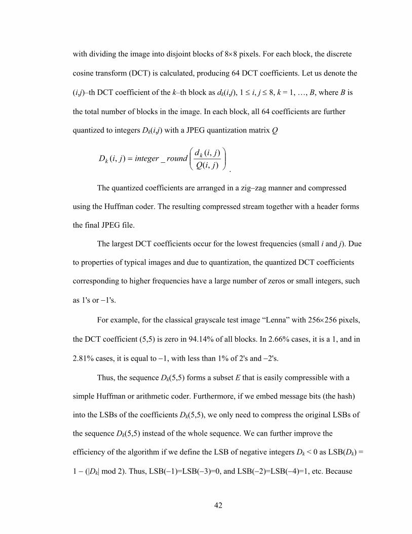
with dividing the image into disjoint blocks of 8×8 pixels. For each block, the discrete
cosine transform (DCT) is calculated, producing 64 DCT coefficients. Let us denote the
(i,j)–th DCT coefficient of the k–th block as dk(i,j), 1 ≤ i, j ≤ 8, k = 1, …, B, where B is
the total number of blocks in the image. In each block, all 64 coefficients are further
quantized to integers Dk(i,j) with a JPEG quantization matrix Q
=
),(),(
_),(jiQjid
roundintegerjiD kk
.
The quantized coefficients are arranged in a zig–zag manner and compressed
using the Huffman coder. The resulting compressed stream together with a header forms
the final JPEG file.
The largest DCT coefficients occur for the lowest frequencies (small i and j). Due
to properties of typical images and due to quantization, the quantized DCT coefficients
corresponding to higher frequencies have a large number of zeros or small integers, such
as 1's or −1's.
For example, for the classical grayscale test image “Lenna” with 256×256 pixels,
the DCT coefficient (5,5) is zero in 94.14% of all blocks. In 2.66% cases, it is a 1, and in
2.81% cases, it is equal to −1, with less than 1% of 2's and −2's.
Thus, the sequence Dk(5,5) forms a subset E that is easily compressible with a
simple Huffman or arithmetic coder. Furthermore, if we embed message bits (the hash)
into the LSBs of the coefficients Dk(5,5), we only need to compress the original LSBs of
the sequence Dk(5,5) instead of the whole sequence. We can further improve the
efficiency of the algorithm if we define the LSB of negative integers Dk < 0 as LSB(Dk) =
1 − (|Dk| mod 2). Thus, LSB(−1)=LSB(−3)=0, and LSB(−2)=LSB(−4)=1, etc. Because
42

DCT coefficients Dk have a symmetrical distribution with zero mean, this simple measure
will increase the bias between zeros and ones in the LSB bit–stream of original DCT
coefficients.
DCT coefficients Dk(i,j) corresponding to higher–frequencies will produce a set E
with a larger bias between zeros and ones, but because the quantization factor Q(i,j) is
also higher for such coefficients, the distortion in each modified block will also be higher.
To obtain the best results, one should use different DCT coefficients for different JPEG
quality factors to minimize the overall distortion and avoid introducing easily detectable
artifacts.
Below, we give a pseudo–code for lossless authentication of grayscale JPEG files.
3.7.2. Algorithm for Invertible Authentication of JPEG Files
1. Based on the JPEG quality factor, determine the set of L authentication pairs
(i1,j1), (i2,j2), …, (iL,jL), 1≤ il, jl ≤ 8, in middle frequencies.
2. Read the JPEG file and use Huffman decompressor to obtain the values of
quantized DCT coefficients, Dk(i,j), 1 ≤ i, j ≤ 8, k = 1, …, B, where B is the total number
of blocks in the image.
3. Calculate the hash H of the Huffman decompressed stream Dk(i,j).
4. Seed a PRNG with a secret key and follow a random non–intersecting walk
through the set E={D1(i1,j1), …, DB(i1,j1), D1(i2,j2), …, DB(i2,j2), …, D1(iL,jL), …,
DB(iL,jL)}. There are L×B elements in the set E.
5. While following the random walk, run the adaptive context–free lossless
arithmetic compression algorithm for the least significant bits of the coefficients from E.
While compressing, check for the difference between the length of the compressed bit–
43

stream C and the number of processed coefficients. Once there is enough space to insert
the hash H, stop running the compression algorithm. Denote the set of visited coefficients
as E1, E1 ⊆ E.
6. Concatenate the compressed bit–stream C and the hash H and insert the
resulting bit–stream into the least significant bits of the coefficients from E1. Huffman
compress all DCT coefficients Dk(i,j) including the modified ones and store the
authenticated image as a JPEG file on a disk.
3.7.3. Integrity Verification:
1. Based on the JPEG quality factor, determine the set of L authentication pairs
(i1,j1), (i2,j2), …, (iL,jL), 1 ≤ il, jl ≤ 8.
2. Read the JPEG file and use Huffman decompressor to obtain the values of
quantized DCT coefficients, Dk(i,j), 1 ≤ i, j ≤ 8, k = 1, …, B.
3. Seed a PRNG with a secret key and follow a random non–intersecting walk
through the set E={D1(i1,j1), …, DB(i1,j1), D1(i2,j2), …, DB(i2,j2), …, D1(iL,jL), …,
DB(iL,jL)}.
4. While following the random walk, run the context–free lossless arithmetic
decompression algorithm for the least significant bits of the coefficients visited during the
random walk. Once the length of the decompressed bit–stream reaches B+|H| (the number
of 8×8 blocks in the image plus the hash length), stop the procedure.
5. Separate the decompressed bit–stream into the LSBs of visited DCT
coefficients and the extracted candidate for hash H'. Replace the LSBs of all visited
coefficients with the decompressed bit–stream and calculate the hash H of the resulting
stream of all quantized DCT coefficients Dk(i,j), 1 ≤ i, j ≤ 8, k = 1, …, B.
44

6. Compare H' with H. If they agree, the JPEG file is authentic and the original
JPEG image is obtained. If H≠H', the image is deemed non–authentic.
7. The selection of the L authentication coefficients can be adjusted according to
the quality factor to minimize the distortion and other artifacts. For example, using L=3
coefficients (5,5), (4,6), and (6,3) in a random fashion will contribute to the overall
security of the scheme because the statistical artifacts due to lossless authentication will
be more difficult to detect.
For color JPEG images, it is advisable to use the chrominance instead of the
luminance as it introduces much less visible distortion into the image. [Table 3.3] shows
the distortion measured using the PSNR.. In the experiments, 128 (4,000) bits were
embedded using one fixed DCT coefficient (6,6), and three color test images; P1, P2, and
P3. The JPEG images in [Figure 3.3], were obtained by saving raw bitmaps as JPEGs
with four different quality factors in PaintShop Pro 7.0.
Table 3.2 Distortion for Lossless Embedding of 128 (4,000) Bits
F
Distortion (dB) Test Image JPEG 90%
JPEG 85%
JPEG 75%
JPEG 50%
P1 (512×330)
55.0 (42.0)
52.0 (38.8)
48.0 (34.6)
43.0 (28.8)
P2 (256×256)
50.5 (38.6)
47.8 (35.3)
44.0 (30.0)
37.6 (25.2)
P3 (878×586)
59.7 (46.4)
56.6 (43.3)
53.6 (39.2)
47.2 (33.4)
igure 3.3 Three Test Images
P1, P2, and P345

3.7.4. Lossless Authentication of JPEG Files (Method 2)
The idea for the second method is quite simple. If for a given DCT coefficient (i,j)
the quantization factor Q(i,j) is even, we could divide it by two and multiply all
coefficients Dk(i,j) by two without changing the visual appearance of the image at all.
Because now all Dk(i,j) are even, we can embed any binary message into the LSBs of
Dk(i,j) and this LSB embedding will be trivially invertible.
If Q(i,j) is odd, we replace it with floor(Q(i,j)/2) and multiply all Dk(i,j) by two. In
this case, we need to include a flag to the hash telling us that Q(i,j) was originally odd in
order to be able to reconstruct the original JPEG stream during verification. Because this
method uses a non–standard quantization table, the table must be included in the header
of the authenticated image. Because the table entry Q(i,j) will not be compatible with the
rest of the table, this authentication method is steganographically obvious.
Method 2 Q(i,j)→ 1 Image QF (6,6) (5,4) (4,2)
50 66.6 (54.4) 66.2 (54.6) 66.6 (54.2) 75 66.9 (55.0) 66.5 (55.2) 67.0 (54.8) 85 66.5 (55.0) 66.0 (55.0) 66.6 (54.8)
P1 512×330
90 66.9 (55.1) 66.7 (55.1) 67.0 (54.7) 50 62.0 (53.5) 61.8 (53.1) 62.0 (52.7) 75 62.7 (53.5) 62.2 (53.0) 62.5 (52.5) 85 62.3 (53.5) 61.8 (53.0) 62.5 (52.6)
P2
256×256 90 62.5 (53.5) 62.3 (53.1) 62.2 (52.5) 50 70.8 (56.8) 70.3 (56.4) 70.6 (56.7) 75 71.4 (57.8) 71.4 (57.4) 71.8 (57.7) 85 71.4 (58.0) 70.6 (57.6) 71.2 (57.9)
P3
878×586 90 71.7 (58.1) 71.5 (57.7) 71.6 (57.9)
Table 3.3 Method 2 Q(i,j)→ 1
46

For Method 2, Q(I,j)→ 1: The distortion for lossless JPEG authentication and for
embedding 4000 bits in an invertible manner (numbers in parenthesis) is shown in [Table
3.4]. Three test images P1, P2, P3, and different JPEG quality factors were used.
For Method 2, Q(i, j)→ Q(i,j)/2: The distortion for lossless JPEG authentication
and for embedding 4,000 bits in an invertible manner (numbers in parenthesis) is shown
in [Table 3.4]. Three test images P1, P2, P3, and different JPEG quality factors used.
Method 2 Q(i,j)→ Q(i,j)/2 Image QF (6,6) (5,4) (4,2)
50 49.3 (34.7) 46.5 (32.3) 49.2 (33.2) 75 54.6 (40.4) 52.0 (38.0) 52.9 (39.1) 85 58.0 (44.4) 55.6 (42.1) 57.0 (43.1)
P1 512×330
90 60.4 (47.1) 58.6 (45.1) 58.7 (46.3) 50 43.7 (31.1) 40.8 (28.2) 43.2 (27.1) 75 50.8 (37.1) 48.1 (34.3) 49.0 (32.9) 85 54.1 (41.2) 51.5 (38.5) 53.1 (37.2)
P2
256×256 90 56.0 (44.3) 54.0 (41.8) 54.7 (40.7) 50 53.6 (39.4) 50.7 (36.4) 53.3 (38.4) 75 59.2 (44.8) 56.6 (42.0) 57.6 (44.2) 85 62.7 (48.4) 60.3 (45.8) 61.7 (47.5)
P3
878×586 90 64.9 (50.5) 63.0 (48.5) 61.7 (50.4)
Table 3.4 Method 2 Q(i,j)→ Q(i,j)/2
One can imagine several other possible implementations of the above idea. For
example, we could replace Q(i,j) with a 1 instead of its half and multiply each Dk(i,j) with
Q(i,j). This version of the method will introduce very small distortion because the DCT
coefficients used for embedding have a quantization factor equal to 1. On the other hand,
the modified stream of quantized coefficients will be less compressible using the
Huffman code thus worsening the overall compression ratio.
[Table 3.5] shows the file sizes before and after embedding the image hash (128
bits), using the coefficient (6,6).
47

Image QF Original Size
Method 1
Method 2 Q(i,j)→ 1
Method 2 Q(I,j)→ Q(i,j)/2
50 19,413 19,617 19,608 19,627 75 30,451 30,711 30,713 30,674 85 41,865 42,138 42,119 42,065
P1 90 53,292 53,574 53,551 53,478 50 7,969 8,181 8,169 8,172 75 11,782 11,997 11,990 11,948 85 15,818 16,025 16,019 15,986
P2 90 19,839 20,060 20,045 20,008 50 52,864 53,452 53,126 53,089 75 81,281 81,606 81,597 81,513 85 110,441 110,721 110,748 110,692
P3 90 140,098 140,389 140,392 140,332
Table 3.5 File Size Comparisons – Before and After Embedding Hash
3.7.5. Summary
In this section, we reviewed two new methods for authentication watermarks for
JPEG files. Both methods can be conveniently added to JPEG compressors and de–
compressors. The distortion due to watermarking is very small and can be completely
removed from the watermarked image if it is deemed authentic.
In the first method, the original LSBs of selected middle frequency coefficients
are losslessly compressed and inserted with the hash of the whole image into the LSBs of
the same coefficients.
Of the two variations of method 2, we selected the Q(i,j)→ Q(i,j)/2 technique for
implementation in the SDC watermarking chip. As it gave us the high embedding
capacity and lower distortion we desired.
This method is more steganographically obvious than the first one, but that is not
a concern in our application.
48

4. Experimental (SDC)
Introduction
This section discusses the process of designing, implementing, and testing an iris
image capture device that is located within the viewfinder of a standard camera. We
detail the procedure of integrating a standard viewfinder into a working bench top
prototype of an iris capture device. The hardware, mechanics, optics, and software of the
SDC bench top prototype are detailed, and the experimental result summarized.
4.1. Capturing the Iris Image
Introduction
Goal of the SDC Iris Image Capture System is: “To capture an iris image that
meets the technical specifications, and image quality♥ of existing iris recognition systems
(FAR of 1 in 1.2 million).
Capturing a well defined, high contrast image of the iris through the viewfinder
was one of the major challenges we encountered in development of our SDC. The Canon
ECF viewfinder system contained several key components that are required in the SDC,
such as the NIR LED illumination system, NIR dichroic mirror (beam–splitter), and a
viewfinder housing.
♥ Some of the components of imaging quality are resolution, image contrast, perspective errors, geometric errors (such as distortion), and depth of field
49

Figu
that r
only
prove
estim
4
until
funct
new
the k
Integ
re 4.1Canon ECF Components
The simplified diagram of the Canon ECF system [Figure 4.1], made it appear
eplacing the Canon view sensor with a Kodak CMOS image sensor would require
a moderate amount of design, implementation, and testing. Unfortunately, this
d not to be the case, since it proved to be a significantly more difficult task than first
ated.
.2. Canon Eye Controlled Focus System
Canon first introduced their ECF system in 1999, but it did not get much attention
2004. That is when Canon greatly increased the speed of many of their camera
ions by improving the DIGIC (Digital Image Core) processor. They introduced the
DIGIC II, as an in the camera hardware based, image processor. Canon transferred
nowledge gained from the development and incorporation of Application Specific
rated Circuits (ASIC) for use on their digital cameras to the analog 35mm cameras.
50
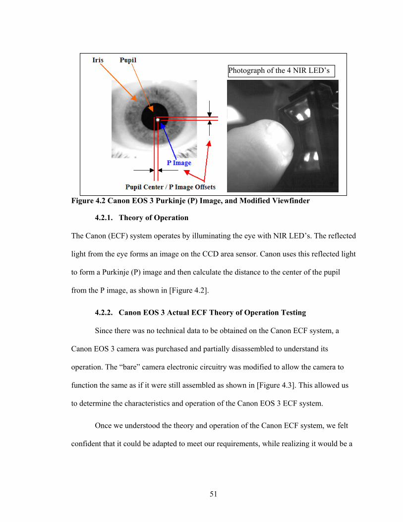
Fig
Th
ligh
to f
fro
Ca
ope
fun
to d
con
Photograph of the 4 NIR LED’s
ure 4.2 Canon EOS 3 Purkinje (P) Image, and Modified Viewfinder
4.2.1. Theory of Operation
e Canon (ECF) system operates by illuminating the eye with NIR LED’s. The reflected
t from the eye forms an image on the CCD area sensor. Canon uses this reflected light
orm a Purkinje (P) image and then calculate the distance to the center of the pupil
m the P image, as shown in [Figure 4.2].
4.2.2. Canon EOS 3 Actual ECF Theory of Operation Testing
Since there was no technical data to be obtained on the Canon ECF system, a
non EOS 3 camera was purchased and partially disassembled to understand its
ration. The “bare” camera electronic circuitry was modified to allow the camera to
ction the same as if it were still assembled as shown in [Figure 4.3]. This allowed us
etermine the characteristics and operation of the Canon EOS 3 ECF system.
Once we understood the theory and operation of the Canon ECF system, we felt
fident that it could be adapted to meet our requirements, while realizing it would be a
51
challenging task. The purchase of an electrical wiring schematic, and a Canon viewfinder
assembly for the Canon EOS 3 camera, were helpful in the SDC hardware design phase.
Figure
4.3
a digita
iris into
represe
verify t
from th
4.3 Disassembled Canon EOS 3
. Iris Image Representation
After choosing the iris image as our SDC biometric identifier, we were faced with
l format decision. Which of two possible techniques to transform the image of the
its representative digital form we should choose? The two possibilities were:
1. To losslessly embed the actual iris image xxix.
2. losslessly a bit stream representation of the iris image iii.
Both approaches have certain advantages and disadvantages. A Bit stream
ntation could embed the information in a robust manner, allowing the user to
he image author from a processed image. The need to extract a digital fingerprint
e iris is a difficult task that involves feature extraction and processing. This may
52
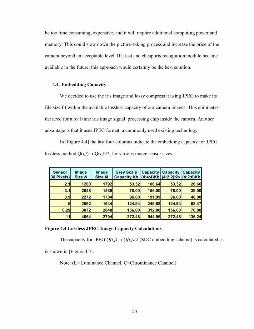
be too time consuming, expensive, and it will require additional computing power and
memory. This could slow down the picture–taking process and increase the price of the
camera beyond an acceptable level. If a fast and cheap iris recognition module became
available in the future, this approach would certainly be the best solution.
4.4. Embedding Capacity
We decided to use the iris image and lossy compress it using JPEG to make its
file size fit within the available lossless capacity of our camera images. This eliminates
the need for a real time iris image signal–processing chip inside the camera. Another
advantage is that it uses JPEG format, a commonly used existing technology.
In [Figure 4.4] the last four columns indicate the embedding capacity for JPEG
lossless method Q(i,j)→ Q(i,j)/2, for various image sensor sizes.
(M
Figu
is sh
Sensor Pixels)
Image Size N
Image Size M
Grey Scale Capacity Kb
Capacity (4:4:4)Kb
Capacity (4:2:2)Kb
Capacity (4:2:0)Kb
2.1 1200 1792 53.32 106.64 53.32 26.663.1 2048 1536 78.00 156.00 78.00 39.003.9 2272 1704 96.00 191.99 96.00 48.00
5 2592 1944 124.94 249.88 124.94 62.476.29 3072 2048 156.00 312.00 156.00 78.00
11 4064 2704 272.48 544.96 272.48 136.24
re 4.4 Lossless JPEG Image Capacity Calculations
The capacity for JPEG Q(i,j)→ Q(i,j)/2 (SDC embedding scheme) is calculated as
own in [Figure 4.5].
Note: (L= Luminance Channel, C=Chrominance Channel):
53

Figure 4.5 Capacity Calculations for JPEG Q(i,j)→ Q(i,j)/2 Embedding
Capacity Calculations for JPEG Q(i,j)→ Q(i,j)/2 Embedding
For gray scale images: Capacity=L×N/8×M/8
*(See note: 5.1) For color images:
If the sample ratio is L:U:V=1:1:1 (i.e. format 4:4:4):
Capacity=2×C×N/8×M/8
If the sample ratio is L:U:V=2:1:1 (i.e. format 4:2:2):
Capacity=2×C×N/8×M/16
If the sample ratio is L:U:V=4:1:1 (i.e. format 4:2:0):
Capacity=2×C×N/16×M/16
*Note: 5.1: Only the two chrominance channels are used to embed data.
Both L and C equal (64–51) =13, (i.e. 13 DCT coefficients in one 8 block are used for data embedding).
The SDC watermarking chip was simulated using software that incorporates the
above capacity formulas, as well as the implementation of Fridrich’s lossless
watermarking embedding and extraction algorithm xx.
4.4.1. Image Size vs. Compression Factor
In the context of iris recognition, we need to know which method of iris image
file size reduction is the best fit for an iris recognition system. Should we decrease the iris
image file size by downsizing the image or by decreasing the quality factor (JPEG
compression ratio)?
54

With the continuing increase in image sensor sizes, the embedding capacity will
soon be less of a factor. The largest iris image size obtained was 170Kb.
The following [Figure 4.6] illustrates the results of compressing a 170Kb gray
scale iris image file, with actual N × M dimensions of 632 pixels 472 pixels (Paint Shop
Pro software was used):
Figure 4.6 Com
Accordin
compression, we
successful iris r
quality and detai
image is of little
4.5. Viewfin
Before b
assumptions mad
furnish us with d
unknown questio
CMOS SENSOR = 632 × 472 (170K) Quality Factor % (Q) File Size
90 58.7K 80 31.0K 70 20.8K 60 15.6K
pressed Iris Image File Sizes Experiment Results
g to Daugmanxxxii, if there is a decision between image size and
should always maintain the largest image size possible. That is because
ecognition is possible with very large compression ratios. Both iris image
l are important, but without sufficient iris image details, a high quality
use in an iris recognition system.
der System Design Concept
eginning any lens system design, we must consider the constraints and
e about the existing Canon viewfinder assembly. Canon could not
etail specific camera technical specifications. We had to solve the
ns by physical, electrical, and optical testing and actual measurements.
55

Our initial concept was to design and test a basic iris capture system consisting of
a CMOS sensor and a single lens, as shown in [Figure 4.7].
Fig
wa
spa
the
mo
Fig
ure 4.7 Initial Iris Capture Design Concept
Some of the unknown specifications included items, such as the NIR LED
velength, types of glass used in the viewfinder lenses, their focal lengths and their lens
cing, and dichroic mirror specifications, as shown in [Figure 4.8]. These are but a few
initial design considerations, constraints, or assumptions we encountered in the
dification of the viewfinder assembly.
Viewfinder Physical Measurements Viewfinder Optical Constraints ure 4.8 Examples of Viewfinder Design Constraints
56

The viewfinder was disassembled and measurements taken to design the simple
lens system within the constraints of the viewfinder assembly, as shown in [Figure 4.10]
Figure 4.9 Disassembled Viewfinder
[Figure 4.10] illustrates that even a simple lens system has many factors that must
be considered before we can begin the design of our SDC.
Figure
57
4.10 Viewfinder Component Measurements

Using the formulas in [Figure 4.11], from the Edmunds Optics web site {Appendix
B.}, we calculated our optical parameters.
Figure 4.11 M
A desc
Figure 4.12 O
agnifications and Focal Length Formula
ription of the formula nomenclature is shown in [Figure 4.12].
Hi,Ho Image and object height, respectively. This represents HALF of the actual full image and object size. In afocal systems, this represents half of the full beam waist.
I, O Image and object distance measured from the lens closest to the image and object respectively.
Fi Fo Focal length of the lens closest to the image and object, respectively.
F Effective focal length of the entire lens system.
M Magnification is the system’s ability to produce an enlarged/reduced image or projection of an object.
D Distance between two elements.
θ FULL angle of the cone of light accepted or emitted by a lens system (closely linked to numerical aperture).
αi, αo Angular HALF field of view in infinite conjugate systems.
TP Throughput is the system’s ability to transfer light.
F/# F/# is the lens’ ability to focus light.
ptical Formula Nomenclature
58

4.6. Viewfinder System Design Calculations
The SDC viewfinder is a typical Finite/Finite Conjugate lens application (Refer to
Edmunds web site for detailed information {Appendix B.}). We can begin by stating our
problem: We want to capture an object (iris) of 10mm in size (Ho) on a CMOS image
sensor that has a horizontal (Iris) sensing distance (Hi) of 3.7mm (Max).
Let us begin by calculating the required magnification (M) of the system:
M= Hi /Ho, (3.7mm/10.0mm = –0.37). This gives us an overall system
magnification of (M) = –0.37 (All objective distances are negative). Clarifying the above
formula in [Figure 4.11] is as follows:
F = O × I / O + I
(Note: All objective distances are negative). F = Fo × Fi / Fo + Fi –d
M = I / O = F / (F + O) = Hi / Ho
M = I / O = –Fi / Fo = Hi / Ho
Since we now know M = –0.37, our viewfinder housing size is our major limiting
design restriction. We simply measured the maximum distance in the viewfinder to
current ECF sensor to be approximately 50mm
Substituting in the above formula, F = O × I / O + I, for I=50mm, and O=10mm,
gives us a first lens choice of 8.3mm Effective Focal Length (EFL).
We now had enough information to design and build a simple iris capture system,
and begin the initial proof of concept experiments. The major issue remaining was iris
illumination. The Canon viewfinder was equipped with eight NIR LED’s that were
properly positioned to reflect off of the pupil of the eye, which is perfect for our SDC
application. The only unknown was their operational wavelength. We checked with many
59

sources in the electronic/optics industry and were not able to identify the part by number
or physical characteristics. Based on recommendations from the manufactures, we
estimated their wavelength to be over 900nm. This proved to be correct, however,
subsequent testing indicated that that was not the ideal wavelength for maximum iris
image contrast.
Edmunds Optics have a large off the shelf selection of Near IR Achromat doublet
lenses that are designed to provide the smallest spot size possible for polychromatic light
between 700 and 1100nm. [Figure 4.13]
Three NIR Achromat doublet lenses with focal lengths of 5mm, 10mm, and
15mm, with D=3mm were ordered for the initial iris image capture system
experimentation.
Figure 4.13 Near IR Achromat Doublet Lens Reflection Curve Chart
4.7. Focal Length Experimentation Results
The image was encouraging, but they all had magnification issues:
60

The F=5 mm, lens had too much magnification and very poor image quality, as
shown in [Figure 4.14], the first iris image that we captured..
Figure 4.14 F
Neithe
have better im
4.8. A Mu
We now
system to mee
obtain the ima
We cou
lens system ha
optical defects
Rome, NY, wa
the multiple le
The sim
magnification,
irst Single Lens Iris Image Captured (F=5mm, D=3mm)
r the 10mm and 15mm lenses had enough magnification, but appeared to
age details.
ltiple Lens Design Solution
faced a more complex lens design problem. We needed a multiple lens
t our previously mentioned iris image constraints and requirements, yet still
ge quality needed for an accurate iris recognition system.
ld no longer use a few basic formulas to design such a system. A multiple
s a much higher degree of complexity as well as the possibility of addition
. An optical engineer, (Ms. R. Bussjager) with the USAF Research Lab at
s willing to use their sophisticated lens design software to assist us with
ns design.
ulation software, trace results indicate, why our initial iris images had
and quality issues as shown if [Figure 4.15].
61

Iris Image Rays Overshoot Sensor
Figure 4.15 Ray Trace Results for Single Element Lens Designs
In [Figure 4.15], the 5mm lens is shown with too much magnification (–0.19),
however the rays from the object plane (Iris image) do not overshoot the image sensor.
The 10mm lens does not provide enough magnification (–0.478), and one can
notice that rays from the top of the iris overshoot the area on the CMOS image sensor.
The 15mm lens performance is as expected, showing an even larger CMOS image
sensor overshoot.
Figure 4.16 Obtaining the Solution
Software simulations were performed on alternative single lens types for use in
the viewfinder, but no good choices were found. When using only a single lens, the ray
tracing analysis showed large effects of aberrations, such as spherical, coma, and field
curvature.
Additional software simulations were performed using a two–lens system in
conjunction with the viewfinder lens. For our “proof of concept” purposes, an intense
lens combination design is not necessary. The diagram in [Figure 4.17] shows a first cut
analysis for a dual lens system.
62

Note: All lens design diagrams
were provided by R. Bussjager.
Figure 4.17 Ray Trace Diagram for a Dual Lens System
To keep the costs down, we desired to use our existing Edmund lenses with F=15
mm and D=3mm, combined with an Edmund lens with F=30 mm and D=6.25mm. The
ray trace diagram illustrated in [Figure 4.17] indicated that this combination would yield
a magnification of –0.33. This is slightly less than the necessary –0.37 magnification
needed, so the image of a 10 mm iris should just under-fill the camera sensor, leaving
room for a slightly larger iris.
If our calculations and the necessary assumptions were correct, there should be no
vignetting of the iris image. With this encouraging information, we decided to implement
the lens design as our initial test system.
In conclusion, after significant design modifications, additional simulations, and
optical parts fabrication, we implemented the recommend initial multi–element lens
combination with the following specifications:
63

• Lens 1 is a NIR Achromat doublet lens: F=30 mm and D=6.25 mm lens.
• Lens 2 is a NIR Achromat doublet lens: F=15mm and D=6.25mm lens.
• The type of glass used in both of these lenses is BK7 and SF5.
The initial results of the above lens design were encouraging, as shown in the first
dual lens iris image obtained through the SDC viewfinder [Figure 4.18].
Figure 4.18 First Dual Lens Image (F=15mm, D=6.25mm & F=30mm, D=6.25mm)
The following is an illustrated parts diagram of the components that were replaced
in the Canon viewfinder [Figure 4.19] to construct the SDC Iris Image Capture
viewfinder [Figure 4.20]:
64
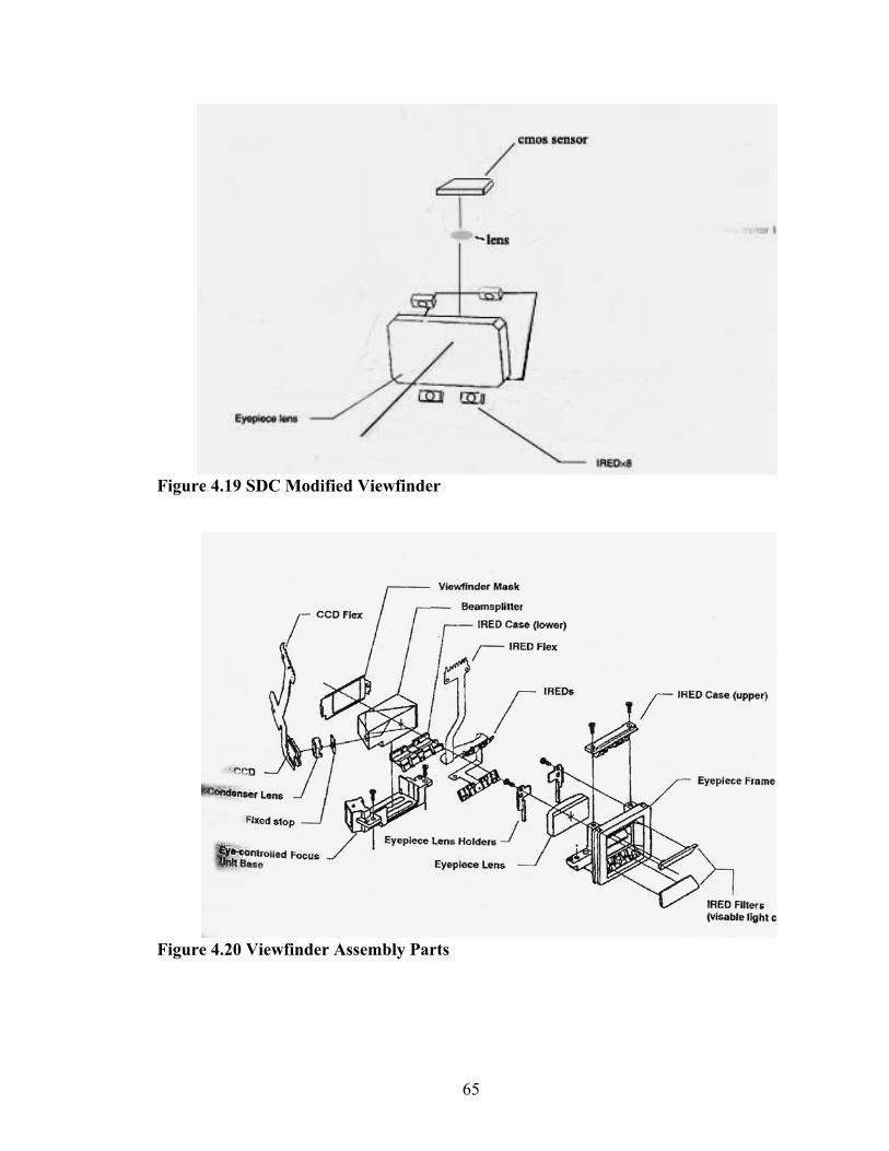
Figure 4.19 SDC Modified Viewfinder
Figure 4.20 Viewfinder Assembly Parts
65

4.9. The NIR LED Experiments
After our initial meeting, and several e–mail follow up questions with Professor
Daugman, he indicated that the initial iris images that we sent to him for image
compression questions, were of too low a contrast level to achieve reliable iris
identification.
Figu
Initial @ 960nm Iris Image Initial (960nm) Iris Sample Image (Low Contrast)
850nm (High Resolution) IMAQ System
New (850nm) Sample Iris Image (Higher Contrast)
re 4.21 NIR LED 960nm and 850nm Wavelength Comparisons
66

Daugman suspected the low contrast was a result of the high wavelength
(Approximately 960nm) of the NIR LED’s in the original Canon viewfinder. Additional
experiments were performed with lower wavelength (850nm) NIR LED’s, and the results
sent to Daugman for his evaluation. The new 850nm NIR LED iris images were now
deemed to be of high enough quality for use in an iris recognition system [Figure 4.21].
4.10. A New Prototype Viewfinder Assembly
Although the new prototype viewfinder assembly was quickly constructed to be
functional, but not esthetically pleasing [Figure 4.22], the resulting images it obtained
exceeded our expectations. The holes for the NIR LED’s were made with a hot soldering
iron, and then we centered the 4 new (850nm) NIR LED’s to the top and bottom of a
spare viewfinder housing. We held them in an approximate alignment by melting the
viewfinder housing plastic around them.
Adding two additional NIR LED’s, to the left and right side of the viewfinder,
they would provide a more uniform illumination for the iris images. We plan to perform
additional testing of even lower wavelength NIR LED’s.
Figure 4.22 Ne
w Prototype Viewfinder Assembly
67
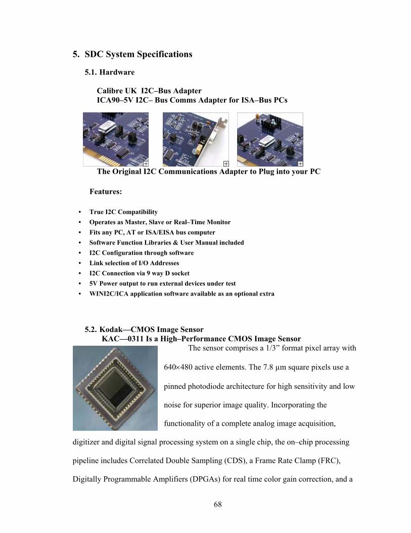
5. SDC System Specifications
5.1. Hardware
Calibre UK I2C–Bus Adapter ICA90–5V I2C– Bus Comms Adapter for ISA–Bus PCs
The Original I2C Communications Adapter to Plug into your PC
Features:
• True I2C Compatibility • Operates as Master, Slave or Real–Time Monitor • Fits any PC, AT or ISA/EISA bus computer • Software Function Libraries & User Manual included • I2C Configuration through software • Link selection of I/O Addresses • I2C Connection via 9 way D socket • 5V Power output to run external devices under test • WINI2C/ICA application software available as an optional extra
5.2. Kodak—CMOS Image Sensor KAC—0311 Is a High–Performance CMOS Image Sensor
The sensor comprises a 1/3” format pixel array with
640×480 active elements. The 7.8 µm square pixels use a
pinned photodiode architecture for high sensitivity and low
noise for superior image quality. Incorporating the
functionality of a complete analog image acquisition,
digitizer and digital signal processing system on a single chip, the on–chip processing
pipeline includes Correlated Double Sampling (CDS), a Frame Rate Clamp (FRC),
Digitally Programmable Amplifiers (DPGAs) for real time color gain correction, and a
68

10–bit Analog to Digital Converter (ADC) that converts the analog data to a 10–bit
digital word stream. This fully differential analog signal–processing pipeline provides
improved noise immunity, signal to noise ratio, and system dynamic range.
5.3. N
N
digital ca
Kodak KAC—0311 Image Sensor Specifications
ational Instruments
I PCI—1424 (Frame Grabber)
The National
Instruments PCI–1424 digital
image acquisition boards are
designed to acquire color and
grayscale images and to control
meras. Designed for high–speed, large–image, high–resolution digital image
69
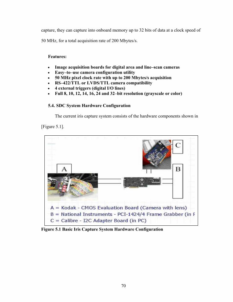
capture, they can capture into onboard memory up to 32 bits of data at a clock speed of
50 MHz, for a total acquisition rate of 200 Mbytes/s.
Features:
• Image acquisition boards for digital area and line–scan cameras • Easy–to–use camera configuration utility • 50 MHz pixel clock rate with up to 200 Mbytes/s acquisition • RS–422/TTL or LVDS/TTL camera compatibility • 4 external triggers (digital I/O lines) • Full 8, 10, 12, 14, 16, 24 and 32–bit resolution (grayscale or color)
5.4. SDC System Hardware Configuration
The current iris capture system consists of the hardware components shown in
[Figure 5.1].
Figure 5.1 Basic Iris Capture System Hardware Configuration
70
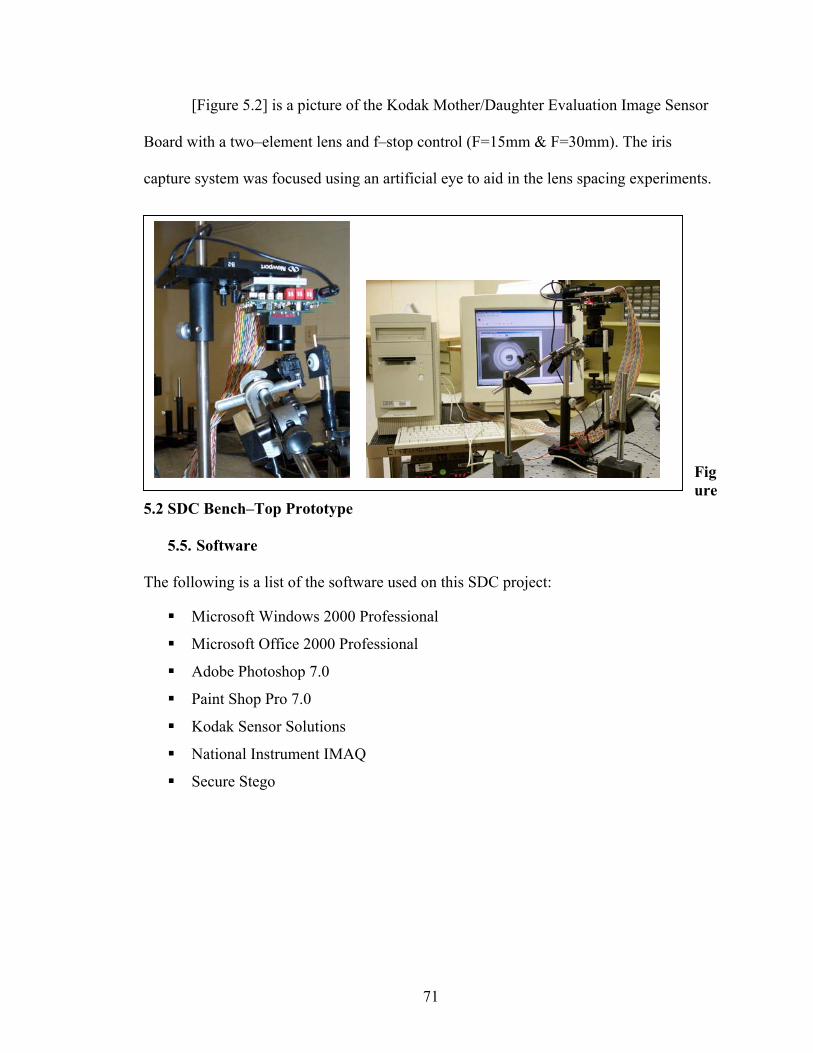
[Figure 5.2] is a picture of the Kodak Mother/Daughter Evaluation Image Sensor
Board with a two–element lens and f–stop control (F=15mm & F=30mm). The iris
capture system was focused using an artificial eye to aid in the lens spacing experiments.
Figure
5.2 SDC Bench–Top Prototype
5.5. Software
The following is a list of the software used on this SDC project:
Microsoft Windows 2000 Professional
Microsoft Office 2000 Professional
Adobe Photoshop 7.0
Paint Shop Pro 7.0
Kodak Sensor Solutions
National Instrument IMAQ
Secure Stego
71
6. Conclusions and Future Work
6.1. Conclusions
In this dissertation we proposed a new concept of a Secure Digital Camera that
offers a solution to the evidentiary problems associated with verifying the integrity,
establishing the origin, and authenticating a digital image. The SDC will not only
eliminate the current evidentiary problems, but will simplify and strengthen the chain of
custody procedures for digital images.
We explained how the camera (SDC) losslessly embeds the photographer’s iris
image, the hash of the scene image, date, time, and other camera/picture information into
the image of the scene. The embedding process depends on a secret camera key. The
embedded data can be later extracted to verify the image integrity, establish the image
origin and verify the image authenticity (identify the camera and the photographer). The
watermark is not only invisible but also completely removable (lossless). The use of the
iris as a biometric reliably verifies the photographer. Secure cryptographic hashes (e.g.,
MD5) guarantee that no modifications can be made to the image that cannot be detected.
Our Secure Digital Camera (SDC) provides a scientifically verifiable
authentication method for its digital images by proving that they:
• Were not tampered with (Integrity).
• Were taken by this particular camera (Origin)
• Were taken by a specific person (Authorship).
72

6.2. Future Work
We would like to automate as much of the manual SDC process as possible. By
taking it from a bench–top prototype to a system that resembles a camera would make a
more impressive demonstration for my supporters as well as potential manufacturers.
We would also like to make additional experiment with various wavelength NIR
LED’s, in addition to the many small issues, such as the effects larger diameter lenses
have on image quality.
If current trends in electronic miniaturization and increased computing power
continue, it would be interesting to actually implement the watermarking chip in
hardware. The SDC watermarking chip seems feasible with current technology.
To implement a real time “in the camera” hardware iris recognition system would
be challenging with current technology, but foreseeable in the near future.
73

GLOSSARY
Achromat Lens (Achromatic Doublet): Two lenses, usually one of crown glass and one flint glass, cemented together. Corrects for chromatic and spherical aberrations. Can also be air spaced.
Acquire: A method of locating images on peripheral devices (such as scanners and digital cameras) and adding them to your hard disk drive; taking screen captures.
Additive Colors: When the colors red, green, and blue are added together, they become white.
Advanced Encryption Standard (AES): New encryption standard to be approved by NIST for next 20–30 years use.
Afocal: Refers to an optical system that does not form an image. A telescope with an eyepiece is afocal, because it does not form an image of its own (the optics of the eye must be used as a “re–imager”). Literally, “without a focal length”; an optical system with its object and image point at infinity.
Algorithm: A set of mathematical rules (logic) used in the processes of encryption and decryption. The specific process in a computer program used to solve a particular problem.
Alias: An assumed name (dummy) mail address that routes the message to all real addresses associated with the assumed name.
Aliasing: An effect caused by sampling an image (or signal) at too low a rate. It makes rapid change (high texture) areas of an image appear as a slow change in the sample image. Once aliasing occurs, there is no way to accurately reproduce the original image from the sampled image.
American National Standards Institute (ANSI): Represents the U.S. in the ISO. A private standards body that develops industry standards through various Accredited Standards Committees (ASC). The X9 committee focuses on security standards for the financial services industry.
American Standard Code for Information Interchange (ASCII): The standard code, using a coded character set consisting of 7–bit coded characters (8 bits including parity check), used for information.
Analog to Digital Converter (A/D Converter): A device that converts analog information (a photograph or video frame) into a series of numbers that a computer can store and manipulate.
Analog: Analog transmitted data can be represented electronically by a continuous wave form signal. Examples of analog items are traditional photographed images and phonograph albums.
Anonymity: Of unknown or undeclared origin or authorship, concealing an entity’s identification.
74

Application: Information processing according to a set of instructions to accomplish a given end. Application examples: electronic mail, credit card verification, electronic data interchange, database search, LAN/WAN connections, remote computing services, distributed data processing, information gateways, international access services, frame–relay services, ATM networks, electronic publishing, electronic trading, authentication, database SQL, etc.
Archive: Long–term storage of data or images. Archiving is generally accomplished on some form of magnetic media; such as disk or tape, or optical media; such as Writable CD.
Artifact: An undesirable degradation of an electronic image. Usually occurs during the electronic capture, manipulation, or output of an image.
Aspect Ratio: The ratio of horizontal to vertical dimensions of an image (35mm slide frame is 3:2, TV 4:3, HDTV 16:9, 4X5 film 5:4).
Asymmetric Key Encryption: A separate but integrated user key pair comprised of one public key and one private key. Each key is one way meaning that key used to encrypt information and can not be used to decrypt information.
Asymmetric: Do not need the same key on each end of a communication link.
Asynchronous: Character–by–character or cell–by–cell or data unit–by–data unit transfer. Data units from any one source need not be periodically spaced within the overall data unit stream.
Audit: The process of examining the history of a transaction to find out what happened. An operational audit can be an examination of ongoing activities to determine what is happening.
Authentication Key Exchange Protocol (AKEP): Key transport based on symmetric encryption allowing two parties to end up with a shared secret key, secure against passive adversaries.
Authentication: The process of ensuring the identity of the connecting user or participants exchanging electronic data. Makes sure the person or server at either end of a connection is who they/it claim to be and not an impostor.
Authorization: To convey official sanction, access or legal power to an entity.
Bayer Filter: A color filtering array for RGB colors. It uses subunits of four pixels. There are two green sites for every red or blue site. This is because cone cells in the human eye are more sensitive to green light than other colors.
Beamsplitter: An optical component that divides light (i.e., a beam) into two separate portions (beams). When the component is inserted into an optical path at a specific angle (typically 45 degrees), a portion of the beam will be diverted (reflected) in a different direction (typically 90 degrees from the input beam). A beamsplitter will reflect a portion of the incident energy, absorb a relatively small portion, and transmit the remaining energy. It is essentially an optical window (clear glass or film) that has a metallic or dielectric coating on one side with specific reflecting and transmitting characteristics. A
75

plate beamsplitter is the most common type and has a thin glass substrate. They are also known as "mirror–type" beamsplitters due to the reflective nature of the coatings used.
Bi–Level: An image containing only two colors–a background color and a foreground color, for example, a black and white image.
Binary Digit: One of the two symbols (0 & 1) commonly used to represent numerical entries in the binary number system.
Binary: A mathematical base 2, which uses only 1's and 0's to represent numbers. 0001 represents 1 decimal, 0010 represents 2 decimal and so forth. Binary numbers are used indirectly to refer to color depth, as in 24–bit or 8–bit color.
Biometric Accuracy: There are two different methods to rate biometric accuracy: False–Acceptance Rate (FAR) and False–Rejection Rate (FRR). These measures can vary significantly, depending on how you adjust the sensitivity of the mechanism that matches the biometric. For example, you can require a tighter match between the measurements of hand geometry and the user’s template (increase the sensitivity). This will probably decrease the false–acceptance rate, but at the same time can increase the false–rejection rate.
Birthday Attack: A particular class of attack against one–way functions. The technique does not allow the function to be completely inverted, but it does find two inputs that correspond to the same output. It does this by computing the function value of many different randomly generated inputs and searching for identical pairs in the set of outputs. If some function, when supplied with a random input, returns one of k equally–likely values, then by repeatedly evaluating the function for different inputs, we expect to obtain the same output after about 1.2k1/2 trials. If we are trying to find a collision, then by the birthday paradox we would expect that after trying 1.2(2n/2) possible input values we would have some collision.
Bit: A binary digit, a fundamental digital quantity representing either 1 or 0, on or off.
Bitmap (BMP): An image made up of dots, or pixels. Refers to a raster image, in which the image consists of rows or pixels rather than vector coordinates.
Block Cipher: Block algorithms–algorithms that operate on plain text in blocks (strings or groups) of bits.
Block: A string or group of bits that a block algorithm operates on; typical values are 40, 50, 64, 128, 512, 1024, …
Brightness: The value of a pixel in an electronic image, representing its lightness value from black to white. Usually defined as brightness levels ranging in value from 0 (black) to 255 (white).
Brute Force Cracking: The process of trying to recover a crypto key by trying all reasonable possibilities.
Byte: A set of Bits that represent a single character. Usually there are 8 Bits in a Byte, sometimes more, depending on how the measurement is being made (See also Bit).
Cache: A high–speed storage mechanism. The ACD Systems database is a cache.
76

Calibration: The act of adjusting the color of one device relative to another, such as a monitor to a printer, or a scanner to a film recorder. Or, it may be the process of adjusting the color of one device to some established standard.
Caption: A comment or description added to an image. Captions above images are called headers, while captions below are referred to as footers.
Capture: The method of taking a biometric sample from the end user.
CBR–Constant Bit Rate: A type of encoding that maintains a fixed bit rate throughout a file, so that data is sent in a steady stream.
Central Processing Unit (CPU): The chip in a computer where virtually all information is processed.
Certificate (Digital Certificate): An electronic document attached to a public key by a trusted third party which provides proof that the public key belongs to a legitimate owner and has not been compromised.
Certificate Authority: A trusted third party who issues, revokes, and manages certificates, validating that public keys are not compromised and that they belong to the correct owners.
Certification Authority (CA): A trusted third party that creates certificates that essentially notarize the association of an identified entity with a public key and other attributes.
Certification: The process of testing a biometric system to ensure that it meets certain performance criteria. Systems that meet the testing criteria are said to have passed and are certified by the testing organization. The administrative act of approving a computer system, component, product, etc., for use in a particular application; endorsement of information by a trusted entity.
Chain of Custody: A process used to maintain and document the chronological history of the evidence. (Documents should include name or initials of the individual collecting the evidence, each person or entity subsequently having custody of it, dates the items were collected or transferred, agency and case number, victim’s or suspect’s name, and a brief description of the item).
Channel: A piece of information stored with an image. True color images, for example, have three channels–red, green and blue.
Charge–Coupled Device Sensor (CCD): The device in a digital camera or scanner that converts light into proportional (analog) electrical current.
Checksum: A numeric value used to verify the integrity of a block of data. The value is computed suing a checksum procedure. A crypto checksum incorporates secret information in the checksum procedure so that it can’t be reproduced by third parties that don’t know the secret information.
Chi–Square Test: Is a statistical test which computes the probability that there is no significant difference between the expected frequency of an occurrence with the observed frequency of that occurrence. Any statistical hypothesis test in which the test statistic has a chi–square distribution if the null hypothesis is true.
77

Chroma: The color of an image element (pixel) made up of saturation and hue values, but separate from the luminance value.
Chrominance: The color portion of an image comprised of a mixture of hue and saturation or the combination of three primary colors, such as red, green, and blue.
Cipher System (Cryptosystem): The hardware and/or software making up the means to encrypt and decrypt plaintext. Encryption and decryption can be implemented in software on the host computer or in hardware devices placed on the links between computers.
Ciphertext: Data that has been encrypted with a cipher, as opposed to plaintext.
Claim of Identity: When a biometric sample is submitted to a biometric system to verify a claimed identity.
Claimant: A person who is submitting a biometric sample for verification or identification whilst claiming a legitimate or false identity.
Closed–Set Identification: When an unidentified end–user is known to be enrolled in the biometric system. Opposite of ‘Open–Set Identification’.
C–MOUNT: The first standard for CCTV lens screw mounting. It is defined with the thread of 1”(2.54mm) in diameter and 32 threads/inch, and the back flange–to–sensor (CCD, CMOS, JFET) distance of 17.526mm (0.69”). The C–mount description applies to both lenses and cameras. C–mount lenses can be both, C–mount and CS–mount cameras, only in the later case an adaptor is required.
Color Correction: The process of correcting or enhancing the color of an image.
Color Matching/Management System (CMS): Software meant to ensure color matching and calibration between video or computer monitors and any form of hard copy output.
Compact Disc (CD): The abbreviation for, a laser–encoded plastic medium designed to store a large amount of data. A variety of CD formats are available for use by computers.
Compact Disc Drive: A drive mechanism for recording or playing CDs. The most common types are CD–ROM, and WORM (Write Once, Read Many).
Compact Disc, Read–Only Memory (CD–ROM): A non–rewritable CD used by a computer as a storage medium for data. Once written, the data on a CD–ROM can only be read, not changed or altered.
Compact Flash: A type of storage card used in digital cameras to store images captured by the camera. The Compact Flash can then be erased when the images have been transferred or are no longer needed, and reused.
Complementary Metal Oxide Semiconductor (CMOS) Sensor: A type of imaging sensor that capture images taken by digital cameras. A type of semiconductor technology that uses both NMOS (negative polarity) and PMOS (positive polarity) circuits. Since only one of the circuit types is on at any given time, CMOS chips require less power than chips using just one type of transistor sensors (I.e. CCD).
Composite Image: An image made up of two or more sub–images stored separately in a file.
78

Compression: The reduction of data to reduce file size for storage. Compression can be “lossy” (such as JPEG) or “lossless” (such as TIFF LZW). Greater reduction is possible with lossy compression than with lossless schemes.
Conjugate Distances: Is the distance from the lens to the object/source (object distance) and the distance from the lens to the detector/image (image distance). For example, in an infinite conjugate design one of these distances approaches infinity.
Conjugate Sizes: is the size of the object/source (object size) and the size of the detector/image plane (image size). For example, in systems with an infinite conjugate, the conjugate "size" can be expressed as an angle.
Continuous Tone: An image where brightness appears consistent and uninterrupted. Each pixel in a continuous tone image file uses at least one byte each for its red, green, and blue values which permits 256 density levels per color or more than 16 million mixture colors.
Contouring: A visual effect in an image as a result of low brightness resolution which appears as bands of sharp, distinct, brightness change–similar to banding.
Contrast: The relationship between the lightest and the darkest areas of an image. An image with deep shadows, bright highlights and few steps between the two is said to be high contrast. An image with weak shadows, dim highlights and many smooth steps between the two is said to be low contrast. High contrast implies dark black and bright white content. Medium contrast implies a good spread from black to white. Low contrast implies a small spread of values from black to white.
Convert: To change a file from one format to another.
Cropping tool: The cropping tool simulates the traditional method for cropping–that is, trimming photographs.
Cryptanalysis: The art or science of transferring ciphertext into plaintext without initial knowledge of the key used to encrypt the plaintext.
Cryptography: (From Greek kryptós, “hidden”, and gráphein, “to write”) Traditionally, the study of means of converting information from its normal, comprehensible form into an incomprehensible format, rendering it unreadable without secret knowledge – the art of encryption The branch of cryptographic science which deals with the means, methods, and apparatus of converting plain text messages into secret messages and visa versa.
CS–MOUNT: A newer standard for lens mounting. It uses the same physical thread as the C–mount, but the back flange–to–CCD distance is reduced to 12.5mm in order to have the lenses made smaller, more compact and less expensive. CS–mount lenses can only be used on CS–mount cameras.
Cyan, Magenta, Yellow, Black (CMYK): One of several color encoding system used by printers for combining primary colors to produce a full–color image. In CMYK, colors are expressed by the “subtractive primaries” (cyan, magenta, yellow) and black. Black is called “K” or keyline since black, keylined text appears on this layer.
79

Cyclic Redundancy Check (CRC): An algorithm used to detect data transmission errors.
Data Compression: The process of converting data from one format to another format that is physically smaller in size. The same logical information is stored using less physical information.
Data Encryption: The process of changing data from an intelligible format to an unintelligible, but decryptable, format.
Data Integrity: Ensuring information has not been altered by unauthorized or unknown means.
Data key: A crypto key that encrypts data as opposed to a key that encrypts other keys.
Data: Digital information or just information, depending on the context.
Database: An electronic filing system for data–a collection of data organized by fields, records, and files such that a computer program can select desired pieces of the collection. The generic name for anything input to, output from, or stored in a computer. All data must be in digital format.
Decode: To read (or view) a file format. That section of a code book in which the code groups are in alphabetical order, or other systematic order. To convert by codebook, not cryptanalysis.
Decrypt: To convert cipher text into the original plain text using a cryptosystem. Decryption (and encryption ) can be implemented in software on computers or in hardware devices placed on the links between computers.
Default Setting: A preset parameter in computer programs which will be used unless changed by the operator.
Degrees of Freedom: The number of statistically independent features in biometric data.
Densitometer: A tool used to measure the amount of light that is reflected or transmitted by an object.
Depth of Field (DOF): The difference between the closest and farthest distances an object may be shifted before an unacceptable blur is observed at a particular resolution. The DOF is also the amount of object movement (into and out of focus) allowable while maintaining an acceptable focus. With a greater the depth of field, more of the scene near to far is in focus. Lens aperture and scene lighting will greatly influence the DOF.
DES–Data Encryption Standard : National Bureau of Standards. A mathematical algorithm for encrypting (enciphering) and decrypting (deciphering) binary coded information. Encrypting data converts it to an unintelligible form called cipher. Decrypting cipher converts the data back to its original form called plaintext.
Dichroic Coating: A filter or mirror coating that transmits or reflects light depending on wavelength rather than upon polarization.
Dichromatic Mirror, (Chromatic Beam–Splitter): A semi–transparent band pass filter that reflects light shorter than a specific wavelength and transmits light that is longer than that wavelength.
80
Dictionary Attack: A calculated, brute–force attack to reveal a password by trying obvious combinations.
Digital Camera (Still): A camera that records images in digital form on a CCD (Charged Coupled Device), CMOS (Complimentary Metal Oxide Semiconductor) or JFET (Junction Field Effect Transistors) sensor, and stores it on an electronic media such as a flash card. It might also be called a film–less camera. All image sensors use an electronic chip which is comprised of a grid of phototransistors to sense the light intensities across the plane of focus of the camera lens. Unlike traditional analog cameras that record infinitely variable intensities of light, digital cameras record discrete numbers for storage.
Digital Camera Software: Software intended to support users of digital cameras to manage their digital photos.
Digital Certificate: A signed electronic document (digital ID) that notarizes and binds the connection between a public key and its legitimate owner. Similar to how a drivers license or passport proves the owner’s identify. Its purpose is to prevent unauthorized impersonation and provide confidence in public keys.
Digital Image: An image composed of pixels.
Digital Scripts: These are coding commands that turn complex digital imaging tasks into menu options that can be executed with a few steps. Scripts can be written for capture, post–processing, and application–related tasks.
Digital Signature Algorithm (DSA): A public–key digital signature. The DSA algorithm was proposed by NIST for use in DSS. DSA was developed by the US National Security Agency (NSA) to generate a digital signature for the authentication of electronic documents. It can not be used for encryption, only for digital signatures.
Digital Signature Standard (DDS): A NIST proposed standard (FIPS) for digital standards using DSA.
Digital Signature: Information that is encrypted with an entity private key and is appended to a message to assure the recipient of the authenticity and integrity of the message. The digital signature proves that the message was signed by the entity that owns, or has access to, the private key or shared secret symmetric key. Computed by using a set of rules and a set of parameters such that the identity of the signer and the integrity of the data can be verified. An electronic identification of a person or thing created by using a public–key algorithm, intended to verify to a recipient the integrity of the data and the identity of the sender of the data.
Digital Time Stamp: A digital signature, which includes a time and date thereby certifying that the content was signed at a given time. Time Stamps may be made of the data being certified it or on a sufficiently strong hash value of that data.
Digital vs. Analog Information: Digital data is represented by discrete values. Analog information is represented by ranges of values, and is therefore less precise.
Digital Zoom: Allows the user to zoom in on a subject beyond the range provided by the optical zoom lens. Digital zooming crops the center of the digital picture and resizes the new cropped picture to the size of the selected resolution. Because digital zoom removes
81
image information it is preferable not to use it when taking photos meant for enlarged printing.
Digital: A system or device in which information is stored or manipulated by on/off impulses, so that each piece of information has an exact or repeatable value (code).
Digitalization: The process of converting analog information into digital format for use by a computer.
Disc: Term used to describe optical storage media (video disc, laser disc, compact disc), as opposed to magnetic storage systems.
Discrete Cosine Transform (DCT): Is used in the JPEG and MPEG image compression algorithms. Refers to the coding methodology used to reduce the number of bits for actual data compression. DCT transforms a block of pixel intensities into a block of frequency transform coefficients. The transform is then applied to new blocks until the entire image is transformed.
Disk: Term used to describe magnetic storage media (floppy disk, diskette, hard disk), as opposed to optical storage systems.
Dots Per Inch (DPI): The measurement of resolution of a printer or video monitor based on dot density. For example, most laser printers have a resolution of 300 dpi, most monitors 72 dpi, most PostScript images 1200 to 2450 dpi. The measurement can also relate to pixels in an input file, or line screen dots (halftone screen) in a prepress output film. The more dots per inch, the higher the resolution, and therefore quality of the image. For example, 92 DPI means 92 dots horizontally and 92 dots vertically, which equals 8464 dots per square inch.
Download: The transfer of files or other information from one piece of computer equipment to another.
Drag and Drop: The process of moving text, graphics, or photos to different locations in a document.
Driver: A software utility designed to tell a computer how to operate an external device. For instance, to operate a printer or a scanner, a computer will need a specific driver.
Due Diligence: Such a measure of prudence, activity, or assiduity, as is properly to be expected from, and ordinarily exercised by, a reasonable and prudent person under the particular circumstances; not measured by any absolute standard, but depending on the relative facts of the special case.
Effective ISO: Analogous to film speed. A higher number means the camera sensor needs less light to make a good exposure. Higher numbers can help in situations of low light where flash may not be effective, e.g., large interiors in low light.
Encapsulated PostScript (EPS): A graphic file format developed by Aldus, Adobe, and Altsys to allow exchange of PostScript graphic files (image information) between professional graphics programs.
Encipher: To convert a plaintext into unintelligible language or signals by means of cipher system.
82

Encode: To write (or save) a file format.
Encrypt (Encode, Encipher): To convert plain text into unintelligible forms by means of a cipher system (crypto system). Encryption (and decryption) can be implemented in software on computers or in hardware–the set of mathematical logic that actually converts (encrypts/decrypts) data.
Encryption: A method of converting data into a secure format. You need a password or key to read an encrypted file. The act of converting electronic data into a code so that people will be unable to read it. A key or a password is used to decrypt (decode) the encrypted biometric data.
End User: A person who interacts with a biometric system to enroll or have his/her identity checked.
Enrollee (Biometric): A person who has a biometric reference template on file.
Enrolment (Biometric): The process of collecting biometric samples from a person and the subsequent preparation and storage of biometric reference templates representing that person’s identity.
Entropy: A mathematical measurement of the amount of uncertainty or randomness.
Equal Error Rate: The error rate occurring when the decision threshold of a system is set so that the proportion of false rejections will be approximately equal to the proportion of false acceptances.
Exchangeable Image File (EXIF): A standard for storing information, primarily with images that use JPEG compression. Most digital cameras create EXIF information. EXIF information is embedded in the image file.
Export: The process of transporting data from one computer, program, type of file format, or device to another.
Extended Graphics Array (XGA): Is a high–resolution graphics standard introduced by IBM. It provides resolutions of 640 by 480 or 1024 by 768 pixels, and supports simultaneous colors (65 thousand colors). In addition, XGA allows monitors to be non–interlaced.
Extraction (Biometric): The process of converting a captured biometric sample into biometric data so that it can be compared to a reference template.
f-number (Photography): (focal ratio) Is the diameter of the camera lens diaphragm aperture in terms of the effective focal length of the lens. For example, f/11 represents a diaphragm aperture diameter that is one-eleventh of the focal length (or the focal length is 11 times the aperture). Some times called F-stop(see F-stop).
Failure to Acquire Rate: The frequency of a failure to acquire.
Failure to Acquire: Failure of a biometric system to capture and extract biometric data (comparison data).
Failure to Enrol Rate: The proportion of the population of end–users failing to complete enrolment.
83

Failure to Enrol: Failure of the biometric system to form a proper enrolment template for an end–user. The failure may be due to failure to capture the biometric sample or failure to extract template data (of sufficient quality).
False Acceptance Rate (FAR): The probability that a biometric system will incorrectly identify an individual or will fail to reject an impostor. The rate given normally assumes passive impostor attempts.
False Acceptance: When a biometric system incorrectly identifies an individual or incorrectly verifies an impostor against a claimed identity.
False Match Rate: Alternative to ‘False Acceptance Rate’. Used to avoid confusion in applications that reject the claimant if their biometric data matches that of an enrollee. In such applications, the concepts of acceptance and rejection are reversed, thus reversing the meaning of ‘False Acceptance’ and ‘False Rejection’. See also ‘False Non–Match Rate’.
False Non–Match Rate: Alternative to ‘False Rejection Rate’. Used to avoid confusion in applications that reject the claimant if their biometric data matches that of an enrollee. In such applications, the concepts of acceptance and rejection are reversed, thus reversing the meaning of ‘False Acceptance’ and ‘False Rejection’. See also ‘False Match Rate’.
False Rejection Rate (FRR): The FRR is the frequency that an authorized person is rejected access. FRR is generally thought of as a comfort criteria, because a false rejection is most of all annoying. FRR is a non–stationary statistical quantity which does not only show a strong personal correlation, it can even be determined for each individual feature (called personal FRR).
False Rejection: When a biometric system fails to identify an enrollee or fails to verify the legitimate claimed identity of an enrollee.
Federal Information Processing Standards (FIPS): A set of standards developed by the National Institute of Standards and Technology for use by the US government. FIPS use algorithms and cryptographic functions to ensure security. FIPS 140–1 is one of the more commonly known FIPS standards that specifies security requirements related to the design and implementation of cryptographic modules.
Field Of View (FOV): The horizontal or vertical scene size at a given length from the camera to the subject.
Field Test/Field Trial: A trial of a biometric application in ‘real world’ as opposed to laboratory conditions.
File Format: A method for encoding information in a file. Each type of file has a different file format that specifies how the information is organized. Some common image file formats include JPEG, TIFF, BMP, and GIF.
File Server: A computer that serves as the storage component of a local area network and permits users to share its hard disks, storage space, files, etc.
File Transfer: The electrical transfer of a file from one storage or processing unit to another.
84

File: In database terms, a collection of records stored and handled as a single unit. For example, an executive telephone book may be a file consisting of the names, titles and telephone numbers of the executives listed in the company’s human resources database.
Filtering (Biometric): The process of classifying biometric data according to information that is unrelated to the biometric data itself. This may involve filtering by sex, age, hair color or other distinguishing factors, and including this information in an end user’s database record. This term is particularly used in conjunction with Automated Fingerprint Identification Systems.
Filters/Optical: A glass or acetate sheet usually placed over a camera lens for changing characteristics of an image or to create a special effect.
Filters/Software: A program that accepts data as input, transforms it in some manner, and then outputs the transformed data. For example, a software program such as PhotoShop can take blurry pictures and filter them to produce a clearer picture.
Firewire: A very fast external bus that supports data transfer rates of up to 400 Mbps. Firewire was developed by Apple and falls under the IEEE 1394 standard. Other companies follow the IEEE 1394 but have names such as Lynx and I–link.
Fixed Focus Lens: Worry free camera operation. Fixed–focus lenses have their focus distance set to obtain good results within a wide range of distances without the need for a focus mechanism.
Flash Memory: A type of memory chip (Solid–State Removable Storage) that can retain data after the system has been turned off. Its advantage is that digital cameras with flash memory can have batteries go “dead” and yet retain image data. Abbreviated SSD, a solid state disk is a high–performance that contains no moving parts.
Focal Length: The distance from the center of the lens to a plane at which point a sharp image of an object viewed at an infinite position. The focal length determines the size of the image and angle of FOV seen by the camera through the lens. This is the center of the lens to the image pickup device.
Forgery: an unauthorized alteration made with the intent to deceive or defraud
F–Stop: A term used to indicate the speed of a lens. The smaller the F–number the greater amount of light passes through the lens.
Genetic Penetrance (Biometric) The degree to which characteristics are passed from generation to generation.
Gigabyte (GB): A measure of computer memory or disk space consisting of about one thousand million bytes (A thousand megabytes).
Goats (Biometric): Biometric system end users whose pattern of activity when interfacing with the system varies beyond the specified range allowed by the system, and who consequently may be falsely rejected by the system.
Graphic Converter: A digital imaging software application that enables you to convert images and photos from one file format to another.
85
Graphic Interchange Format (GIF): A raster graphic file format developed by CompuServe to exchange image files across multiple platforms. GIFs are also the preferred file format for web graphics because they have small file sizes.
Gray Level: The brightness of a pixel. The value associated with a pixel representing it’s lightness from black to white. Usually defined as a value from 0 to 255, with 0 being black and 255 being white.
Gray Scale: A term used to describe an image containing shades of gray as well as black and white.
Hamming Distance: The number of disagreeing bits between two binary vectors. Used as measure of dissimilarity.
Hardware: The ‘nuts and bolts’ of the computer system, that includes the monitor, CPU, printers, disc drives, etc.
Hash Code: Also known as message digest. A unique fingerprint of data that can be used for image tamper identification or comparison.
Hash Function: One–way hash function–a function that produces a message digest that cannot be reversed to produce the original.
Header: A comment or description added to the top of an image. Also referred to as a caption.
Histogram: A bar graph analysis tool that can be used to identify contrast and dynamic range image problems. Histograms are found in most software programs that are used to manipulate digital images.
Hue: A term used to describe the entire range of colors of the spectrum; hue is the component that determines just what color you are using. In gradients, when you use a color model in which hue is a component, you can create rainbow effects.
Icon: A small graphic symbol or picture on a computer screen that represents a file, folder, disk, or command.
Identification/Identify (Biometric): The one–to–many process of comparing a submitted biometric sample against all of the biometric reference templates on file to determine whether it matches any of the templates and, if so, the identity of the enrollee whose template was matched. The biometric system using the one–to–many approach is seeking to find an identity amongst a database rather than verify a claimed identity. Contrast with ‘Verification’.
Image Processing: Capturing and manipulating images in order to enhance or extract information.
Image Resolution: The number of pixels per unit length of image. For example, pixels per inch, pixels per millimeter, or pixels wide.
Import: The process of bringing data into a document from another computer, program, type of file format, or device.
Impostor (Biometric): A person who submits a biometric sample in either an intentional or inadvertent attempt to pass him/herself off as another person who is an enrollee.
86
Infinite/Finite Conjugate: A lens design in which light from a source (not at infinity) is focused down to a spot. Most video lenses, which take the image of an object at a finite distance away and focus it onto a CCD array, are designed for this scenario.
Infrared Data Association (IrDA): A method of transferring data that relies on an infrared connection rather than a cable connection. Requires IrDA receiving capability on your computer.
Infrared Radiation (IR): Is electromagnetic radiation of a wavelength longer than visible light, but shorter than microwave radiation. The name means “below red” (from the Latin infra, “below”), red being the color of visible light of longest wavelength. Infrared radiation spans three orders of magnitude and has wavelengths between 700nm and 1000nm.
Institute of Electrical and Electronics Engineers (IEEE): Abbreviation of Institute of Electrical and Electronics Engineers. IEEE is an organization composed of engineers, scientists, and students. The IEEE is best known for developing standards for the computer and electronics industry. In particular, the IEEE 802 standards for local–area networks are widely followed.
Integrated Services Digital Network (ISDN): A system of digital phone connections which has been available for over a decade.(post POTS) This system allows voice and data to be transmitted simultaneously across the world using end–to–end digital connectivity.
Integrity: Knowing or having assurance that data or information is transmitted from source to destination without undetected alteration.
International Color Consortium (ICC): Founded in 1993 by 8 industry vendors for creating, promoting and encouraging the standardization and evolution of an open and accessible color management system for hardware and software.
Interpolation: When resizing an image, a process that uses nearby pixels to estimate the color of new pixels added to the larger image.
ISO–International Organization for Standardization: Created the seven layer OSI structure for telecommunications
Joint Photographic Experts Group (JPEG): Is an acronym for Joint Photographic Experts Group, which is the organization that developed the format. for storing high–quality color and grayscale photographs in bitmap form. JPEG provides lossy compression by segmenting the picture into small blocks, which are divided to get the desired ratio; the process is reversed to decompress the image. JPEG uses the JPEG File Interchange Format, or JFIF.
JPEG Compression: A file compression standard established by the Joint Photographic Experts Group that uses a combination of DCT and Huffman encoding to compress images. JPEG is a “lossy” compression algorithm, meaning that it slightly degrades image quality.
JPEG File Interchange Format (JFIF): A minimal file format which enables JPEG bit streams to be exchanged between a wide variety of platforms and applications.
87

Junction Field Effect Transistors (JFET): in which semiconductor channels of low conductivity join the source and drain and in which these channels are reduced and cut off by the junction depletion regions, which reduce the conductivity and cause a voltage to be applied between the gate electrodes. Used for junction field effect transistors.
Key Exchange: The process for getting session keys into the hands of the conversants.
Key Length: The number of bits representing the key size. The longer the key, the stronger it is.
Key Recovery: A mechanism for determining the key used to encrypt some data.
Kilobyte (KB): An amount of computer memory, disk space, or document size consisting of approximately one thousand bytes.
Least Significant Bit (LSB): The LSB is the right most bit in a binary number. For Example 00000001, 1 is the LSB.
Light–Emitting Diode (LED): A semiconductor diode that converts electric energy into electromagnetic radiation at a visible and near infrared frequencies when its pn junction is forward biased.
Liquid Crystal Display (LCD): A flat panel of tiny cells used on most mobile computers in place of a monitor. Or a convenient, full–color display found on a digital camera that lets you view and review your digital pictures when they are taken.
Live Capture (Biometric): The process of capturing a biometric sample by an interaction between an end user and a biometric system.
Local Area Network (LAN): A communications network connected by cables and confined to a single office or building. It enables a group of computers to exchange files and share peripheral devices.
Lossy Compression: A method of reducing image file size by throwing away unneeded data, causing a slight degradation of image quality. Tiff is a lossless file format.
Luminance: The brightness, darkness, and contrast information of an image.
Man–in–the–Middle (MIM): An attack against a public key exchange in which the attacker substitutes his own public key for the requested public key; also called a bucket brigade attack.
Marquee: The outline of dots created by the selection tool on an image when an operator is performing a task such as cropping, cutting, drawing a mask, etc.
Mask: A defined area used to limit the effect of image–editing operations to certain regions of the image. In an electronic imaging system, masks are drawn manually (with a stylus or mouse) or created automatically–keyed to specific density levels or hue, saturation and luminance values in the image. It is similar to photographic lith masking in an enlarger.
Masking (Human Visual System): Generally defined as any interference between two or more visual signals or stimuli that results in an increase or, more often, a decrease of their visibility.
88
Match/Matching: The process of comparing a biometric sample against a previously stored template and scoring the level of similarity. An accept or reject decision is then based upon whether this score exceeds the given threshold.
MD2–Message Digest 2: (Message Digest Algorithm 2) A cryptographic hash function developed by Ronald Rivest in 1989. The algorithm is optimized for 8–bit computers. MD2 is specified in RFC 1319. Although other algorithms have been proposed since, such as MD4, and MD5. Even as of 2004 MD2 remains in use in public key infrastructures as part of certificates generated with MD2 and RSA.
MD4–Message Digest 4: (Message Digest Algorithm 4) A message digest algorithm (the fourth in a series) designed by Professor Ronald Rivest of MIT in 1990. It implements a cryptographic hash function for use in message integrity checks. The digest length is 128 bits. The algorithm has influenced later designs, such as the MD5 algorithm.
MD5–Message Digest 5: (Message Digest Algorithm 5) A standard algorithm that takes as input a message of arbitrary length and produces as output a 128–bit fingerprint or message digest of the input. Any modifications made to the message in transit can then be detected by recalculating the digest. (Similar in concept to a CRC).
Megabyte (MB): An amount of computer memory consisting of about one million bytes.
Megapixel (Mp): This is an approximate measure of an image's resolution. One Mega Pixel equals approximately one million pixels. It is only approximate because it is a term derived by the marketing departments of camera manufacturers, not engineers, and different formulas are used to determine what a Mega Pixel is, including varying the definition of one million pixels.
Message Authentication Code (MAC): Is a short piece of information used to authenticate a message. A MAC algorithm (sometimes termed a keyed hash function) accepts as input a secret key as well as the message, and produces a MAC (sometimes known as a tag). The MAC protects both a message's integrity–by ensuring that a different MAC will be produced if the message has changed–as well as its authenticity–because only someone who knows the secret key could have generated a valid MAC
Message Digest: A number derived from a message. A single change in a character in the message will change the message digest.
Metadata: Information about an image. For example, metadata with images from digital cameras can contain the date and time the picture was taken, the shutter speed, the exposure settings of the camera, and if a flash was used.
Monochrome: An image containing a single color.
Morphing: A special effect used in motion pictures and video to produce a smooth transformation from one object or shape to another.
Most Significant Bit (MSB): In computing, the most significant bit (MSB) is the bit position in a binary number having the greatest value. The MSB is sometimes referred to as the left–most bit.
Motion Picture Experts Group (MPEG): Motion Pictures Experts Group. A body within the International Organization for Standardization (ISO) that established the
89

MPEG–1, MPEG–2, and MPEG–4 digital audio and video compression standards. MPEG is also used to refer to video and audio clips compressed using the MPEG standards and the MPEG standards themselves.
Multimedia: The combination of two or more media into a single presentation. For example, combining video, audio, photos, graphics and/or animations into a presentation.
Multiple Biometric: A biometric system that includes more than one biometric system or biometric technology.
National Institute of Standards and Technology (NIST): An agency of the U.S. government that establishes national standards [http://csrc.nist.gov].
National Science Foundation (NSF): An independent U.S. government agency that sponsors, funds, and fosters research and development in science and engineering. The NSF became involved in wide area networking in the mid 1980s and founded NSFNET, which connected academic and research institutions. NSFNET was later connected to the Advanced Research Projects Agency Network (ARPANET), and eventually developed into the network that we now refer to as the Internet.
National Security Agency (NSA): An agency of the U.S. government responsible for intercepting foreign communications for intelligence reasons and for developing crypto systems to protect U.S. government communications.
Near Infrared (NIR): Near Infrared light is not visible to human eyes, but many celestial objects shine brightly with this light. Typically associated with heat, NIR images show the presence of molecules and complex compounds.
Neural Net/Neural Network: One particular type of algorithm. An artificial neural network uses artificial intelligence to learn by past experience and compute whether a biometric sample and template is a match.
Nickel Metal Hydride Battery: Recommended for digital cameras, these batteries have high energy density (50% more than Ni–Cd) and can be charged over 500 times in their life cycle. They charge very fast and hold their energy longer than other batteries. When they are disposed of they have a low environmental impact.
One–to–a–Few: A hybrid of one–to–many identification and one–to–one verification. Typically the one–to–a–few process involves comparing a submitted biometric sample against a small number of biometric reference templates on file.
One–to–Many: Synonym for ‘Identification’.
One–to–One: Synonym for ‘Verification’.
One–Way Hash: A hash function for which it is extremely difficult to construct two blocks of data that yields exactly the same hash result. Ideally, it should require a brute force search to find two data blocks that yield the same result.
Open–Set Identification (Biometric): Identification, when it is possible that the individual is not enrolled in the biometric system. Opposite of ‘Closed–Set Identification’.
90

Out of Set (Biometric): In open–set identification, when the individual is not enrolled in the biometric system.
Palette: A thumbnail of all available colors to a computer or devices. The palette allows the user to chose which colors are available for the computer to display. The more colors the larger the data and the more processing time required to display your images. If the system uses 24–bit color, then over 16.7 million colors are included in the palette.
Passive Impostor Acceptance: When an impostor submits his/her own biometric sample and claiming the identity of another person (either intentionally or inadvertently) he/she is incorrectly identified or verified by a biometric system. Compare with ‘Active Impostor Acceptance’.
PCMCIA Card: A credit card size memory or PC card that meets the PC Card Standard developed jointly by the Personal Computer Memory Card International Association (PCMCIA) and the Japan Electronic Industry Development Association (JEIDA).
PCX: A popular bitmapped graphics file format, designed by Zsoft, that handles black and white, 2–bit, 4–bit, 8–bit and 24–bit color. A Windows Paintbrush bitmap image standard.
Performance Criteria (Biometric): Pre–determined criteria established to evaluate the performance of the biometric system under test.
Peripheral: A term used to collectively describe computer hardware accessories such as printers, modems, scanners, etc.
Personal Computer (PC): A small, single–user computer based on a microprocessor. In addition to the microprocessor, a personal computer has a keyboard for entering data, a monitor for displaying information, and a storage device for saving data. (Note: Another often used definition for (PC) is Printed Circuit; i.e. printed circuit board).
Personal Computer Memory Card International (PICT): A graphics file format used primarily on Macintosh computers. PICT files can contain both object–oriented and bit–mapped graphics. There are two types: PICT I and PICT II. PICT II is the current standard and supports color up to 24–bit.
Personal Computer Memory Card International Association (PCMCIA): A standard for a credit card–size memory or input/output device that fits into a notebook, laptop or personal computer. The PCMCIA card eliminates the need to have the camera connected to the PC to record pictures.
Photons: The force particles which carry electromagnetic interactions that behave like both a wave and a particle. They possess no mass or charge. Photons move at the speed of light, 300,000,000 meters per second.
Physical/Physiological Biometric: A biometric, which is characterized by a physical characteristic rather than a behavioral trait. Such as:’ Ear Shape’, ‘Face Recognition’, ‘Finger Geometry’, ‘Finger Image’, ‘Hand Geometry’, ‘Iris Recognition’, ‘Palm’, ‘Retina’, ‘Speaker Verification’ and ‘Vein check’. Contrast with ‘Behavioral Biometric’.
PIN (Personal Identification Number): A security method whereby a (usually) four–digit number is entered by an individual to gain access to a particular system or area.
91

Pixel (PICture ELement): The smallest element of a digitized image. Also, one of the tiny points of light that make up a picture on a computer screen. The number of pixels n for a given maximum resolution (w horizontal pixels by h vertical pixels) can be found using the formula: n = wh. This yields e. g. 1.92 megapixels (= 1,920,000 pixels) for an image of 1600 x 1200. The majority of digital cameras have a 3:2, or 4:3 aspect ratio, i.e. w/h = 4/3
Pixels per Inch (PPI): A measurement of how an image is displayed. The greater the number of pixels per inch, the higher the quality of the image.
Plain Old Telephone service (POTS): Refers to the standard telephone service that most homes use. In contrast, telephone services based on high–speed, digital communications lines, such as ISDN. ISDN is not POTS. The main distinctions between POTS and non–POTS services are speed and bandwidth. (POTS is generally restricted to about 52 Kbps) (52,000 bits per second). The POTS network is also called the public switched telephone network (PSTN).
Plain Text: (clear text) The readable data or message before it is encrypted.
Plug and Play: An automated installation process used to connect peripheral devices such as digital cameras to computers. When new devices are plugged into the computer the computer recognizes the device and prompts the user to choose setup options and finish installation. USB devices are plug and play.
Plug–In: A software module that adds functionality to a larger program.
Polychromatic Light: Light of more than one color or wavelength.
Population (Biometric): The set of end–users for the application.
Portable Network Graphics (PNG): Pronounced ping. A new standard that has been approved by the World Wide Web consortium to replace GIF because GIF uses a patented data compression algorithm. PNG is completely patent and license–free.
PostScript: A page description language developed by Adobe Systems, Inc. to control precisely how and where shapes and type will appear on a page. Software and hardware may be described as being PostScript compatible.
Primary Colors: Colors that can produce other colors by mixing them together. For example, in the RGB color model, red, green, and blue are primary colors.
Private Key: The privately held “secret” component of an integrated asymmetric key pair.
Pseudorandom Number Generator (PRNG): A procedure that generates a sequence of numerical value that appear random. Cryptographic PRNGs strive to generate sequences that are almost impossible to predict. Most PRNGs in commercial software are statistical PRNGs that strive to produce randomly distributed data with a sequence that may in fact be somewhat predictable.
Public Key Algorithm: A cipher that uses a pair of keys, a public key and private key, for encryption and decryption; also called an asymmetric algorithm.
92

Public Key: A key used in public key crypto that belongs to an individual entity and is distributed publicly. Others can use the public key to encrypt data that only the key’s owner can decrypt.
Purkinje Images: A threefold image of a single object seen by one person reflected in the eye of another person. This effect is caused by the object being reflected by the surface of the cornea and by the anterior and posterior surfaces of the eye lens.
Random Access Memory (RAM): The most common form of computer memory in which the CPU stores data that is currently in use. RAM is usually volatile memory, meaning that when the computer is turned off, crashes, or loses power it is lost.
Random Number: A number with a value that cannot be predicted. Truly random numbers are often generated by physical events that are believed to occur randomly.
Raster: Raster images are made up of individual dots; each of which have a defined value that precisely identifies its specific color, size and place within the image. (Also known as bitmap images.) Therefore, resizing the image can affect its quality.
Read Only Memory (ROM): This form of memory can be read but not updated or changed by a computer. It refers to specific electronics in a computer; however non–alterable disks like CDs or CD ROMs are another type of read only memory. It is non–volatile because does not disappear when power is shut off.
Real Time Image Processing: A data processing system that responds immediately to the user. Image processing that executes each function immediately and displays it at a high enough resolution to be viewed.
Receiver Operating Curves (ROC): A graph showing how the false rejection rate and false acceptance rate vary according to the threshold.
Recognition (Biometric): The preferred term is ‘Identification’.
Record (Biometric): The template and other information about the end–user (e.g. access permissions)
Resize: To alter the resolution or the horizontal or vertical size of an image.
Resolution: The number of pixels per unit length of image. For example, pixels per inch, pixels per millimeter, or pixels wide. The minimum feature size of the object under inspection. Resolution is also a measurement of the imaging system’s ability to reproduce object detail.
Response Time (Biometric): The time period for a biometric system to return a decision on identification or verification of a biometric sample.
Reusable Password: A password that can be used over and over, as opposed to a one–time password. Most passwords used today are reusable passwords.
RGB: Short for Red, Green, and Blue; the primary colors used to simulate natural color on computer monitors and television sets.
RSA Data Security, Inc. (RSA): Refers to the principles: Ron Rivest, Adi Shamir, and Len Adleman; or to the algorithm they invented. The RSA algorithm is used in public–
93

key cryptography and is based on the fact that it is easy to multiply two large prime numbers together, but hard to factor them out of the product.
Saturation: The degree to which a color is undiluted by white light. If a color is 100 percent saturated, it contains no white light. If a color has no saturation, it is a shade of gray.
Score: The level of similarity from comparing a biometric sample against a previously stored template.
Secret Key Algorithm: A crypto algorithm that uses the same key to encrypt data and to decrypt data; also called a symmetric algorithm.
Secret Key: A (Crypto) key that is used in a secret key (symmetric) algorithm. The secrecy of encrypted data depends solely on the secrecy of the secret key.
Secure: Safe, protected, free from attack or damage.
Seed, Random: A random data value used when generating a random sequence of data values with a PRNG.
Sensor Size: The size of a camera sensor’s active area, typically specified in the horizontal dimension. This parameter is important in determining the proper lens.
Sequence: An ordered arrangement of symbols (letter, digits, etc.) having continuity. The members of a component of a cipher alphabet; the symbols in a row, column, or diagonal of the cipher square in order; key letters or key figures in order.
Serial: A data transfer method used to connect a peripheral, such as a digital camera, to a computer. The serial connection will allow for the peripheral to transfer data to the computer and vise versa.
Session Key: The secret (symmetric) key used to encrypt each set of data on a transaction basis. A different session key or set of session keys is used for each communication session.
Smart Card: Tamper–resistant hardware devices that store private keys & other sensitive information.
Smoothing: Averaging pixels with their neighbors. It reduces contrast and simulates an out–of–focus image.
Square Pixels/Rectangular Pixels: Point and shoot digital cameras utilize camcorder technology. Camcorders use rectangular pixels because TV displays are rectangular. For computers square is better because computer monitors display square pixels. When you start with a rectangular pixel you have to “lob” off part of the pixel to display it. Essentially you lose image data and introduce artifacts with rectangular pixels.
Steganography: Is the art and science of writing hidden messages in such a way that no one apart from the intended recipient knows of the existence of the message; this is in contrast to cryptography, where the existence of the message is clear, but the meaning is obscured. The name comes from Johannes Trithemius’s Steganographia: a treatise on cryptography and steganography disguised as a book on black magic, and is Greek for “hidden writing.”
94

Strong Crypto: Crypto facilities that exceed the standards for lightweight or medium–strength crypto and therefore face significant restrictions under U.S. export rules.
Sub Pixel: On both full–color LCD flat panels and CRT monitors, each pixel is constructed from three sub–pixels for the three colors, spaced closely together. Each single–color sub–pixel is brightened according to the triplicate number reference, and due to their proximity, they create an illusion of being one specially–tinted pixel. A recent technique for increasing the apparent resolution of a color display, named sub–pixel rendering, uses knowledge of pixel geometry to manipulate the three colored sub–pixels separately, which seems to be most effective with LCD displays set at native resolution. This is a form of anti–aliasing, and is mostly used to improve the appearance of text. Microsoft’s Clear Type™, which is available in Windows XP, is an example of this.
Subroutines: A set of instructions, appearing within a computer program, for performing a specific task.
Subtractive Colors: Transparent colors that can be combined to produce a full range of color. Subtractive colors subtract or absorb elements of light to produce other colors.
Symmetric Algorithm: A crypto algorithm that uses the same crypto key for encrypting and decrypting; also called a secret key algorithm.
Symmetric Key Encryption: Process using one and only one key to perform both the encryption and decryption processes.
Synchronous Transmission: The entire message is sent with control information surrounding the text portion of the transmission.
T1: A digital communications line which has a capacity of 1.544 megabits per second (Mbps)
T3: A digital communications line having a capacity of 44.736 Mbps.
Tagged Image File Format (TIFF): The standard file format for high–resolution bit–mapped graphics. TIFF files have cross–platform compatibility.
Tagged Image File Format for Electronic Photography(TIFF/EP): A version of TIFF file format used by Kodak digital cameras to store non–image data with many different types of image data. Timestamp: The dates and times associated with a file.
Template Ageing (Biometric): The degree to which biometric data evolves and changes over time, and the process by which templates account for this change.
Template Size: The amount of computer memory taken up by the biometric data.
Template/Reference Template: Data, which represents the biometric measurement of an enrolee, used by a biometric system for comparison against subsequently submitted biometric samples.
Text: Part of the message containing the basic information which the originator desires to be communicated.
Third Party Test: An objective test, independent of a biometric vendor, usually carried out entirely within a test laboratory in controlled environmental conditions.
95

Threshold/Decision Threshold: The acceptance or rejection of biometric data is dependent on the match score falling above or below the threshold. The threshold is adjustable so that the biometric system can be more or less strict, depending on the requirements of any given biometric application.
Throughput Rate: The number of end users that a biometric system can process within a stated time interval.
Thumbnail: A small, low–resolution version of a larger image file that is used for quick identification or speedy editing choices.
Timestamping: Recording the time of creation or existence of information.
Transparency: Allowing an application to perform on a circuit/connection without impacting on the usual operations or the operators of the circuit.
Triple DES (3DES): An encryption configuration in which the DES algorithm is used three times with three different keys.
Trojan Horse: A program with secret functions that are surreptitiously access information without the operator’s knowledge, usually to circumvent security protections.
True Color Display: A device capable of displaying 16,777,216 colors. Truecolor formerly referred to any device capable of displaying 32,768 colors or more, but hicolor more accurately describes this color level as well as 65,536 colors.
True Color: Color that has a depth of 24–bits and 16.7 million colors.
Trust: A firm belief or confidence in the honesty, integrity, justice, reliability, etc., of a person, company, etc.
TTP (Trust Third Party): A responsible party which all participants involved agree upon in advance, to provide a service or function, such as certification by binding a public key to an entity, time–stamping, or key–escrow.
Type I Error: In statistics, the rejection of the null hypothesis (default assumption) when it is true. In a biometric system the usual default assumption is that the claimant is genuine, in which case this error corresponds to a ‘False Rejection’.
Type II Error: In statistics, the acceptance of the null hypothesis (default assumption) when it is false. In a biometric system the usual default assumption is that the claimant is genuine, in which case this error corresponds to a ‘False Acceptance’.
Universal Resource Locator (URL): The global address of documents and other resources of the World Wide Web (www) These are the internet’s equivalent to addresses.
Universal Serial Bus (USB): The USB offers a simplified way to attach peripherals and have them be recognized by the computer. USB ports are about 10 times faster than a typical serial connection. These USB ports are usually located in easy to access locations on the computer.
Unsharp Masking: A process by which the apparent detail of an image is increased; generally accomplished by the input scanner or through computer manipulation.
96
User: The client to any biometric vendor. The user must be differentiated from the end user and is responsible for managing and implementing the biometric application rather than actually interacting with the biometric system.
Vector Image: An image made up of individual objects instead of pixels. The objects are defined by mathematical equations. You can adjust the size of a vector image and the image remains clear and of high quality. This type of file format is typically used in engineering and architecture.
Verification/Verify: The process of comparing a submitted biometric sample against the biometric reference template of a single enrolee whose identity is being claimed, to determine whether it matches the enrollee’s template. Contrast with ‘Identification’.
Video Graphics Array (VGA): a resolution type that uses analog signals and is only capable of 16 colors @ 640x480 and 256 colors @320x200 respectively. VGA is considered to be the lowest common denominator in graphics display.
Virtual Memory: Disk space on a hard drive that is identified as RAM through the operating system, or other software. Since hard drive memory is often less expensive than additional RAM, it is an inexpensive way to get more memory and increase the operating speed of applications.
Watermark (Digital): A code embedded into digital material that can be used to establish ownership, may be visible or invisible to the user. Font or graphics added to an image, usually to provide copyright protection. A fragile watermark is to detect every possible modification of the image. A semi–fragile watermark is should be insensitive to allowed manipulations, such as lossy compression, or image resizing.
What You See Is What You Get (WYSIWYG): Refers to the ability to output data from the computer exactly as it appears on the screen.
Whitepoint: The whitest area of an image. You can control the intensity of the white in an image by adjusting the whitepoint.
Working Distance: .The distance from the front of the lens to the object under inspection.
World Wide Web (www): Is a system of Internet servers that support specially formatted documents. The documents are formatted in a language called HTML (HyperText Markup Language) that supports links to other documents, as well as graphics, audio, and video files. This means you can jump from one document to another simply by clicking on hot spots. Not all Internet servers are part of the World Wide Web.
Write Once; Read Many (WORM): Most common to optical disks, WORM refers to data storage that cannot be changed once written. However, it may be read as many times as desired. (CD–R)
Zero Effort Forgery: Where an impostor uses his or her own biometric sample and claims the identity of a different enrollee.
Zoom Lens: A variable length lens that can be adjusted from wide angle to telephoto. The higher the number, the greater the range of the zoom.
97

Appendix A FEDERAL RULE 901 –– Requirements
ARTICLE IX. AUTHENTICATION AND IDENTIFICATION
RULE 901.REQUIREMENT OF AUTHENTICATION OR IDENTIFICATION
(a) General Provision. The requirement of authentication or identification as a condition
precedent to admissibility is satisfied by evidence sufficient to support a finding that the
matter in question is what its proponent claims.
(b) Illustrations. By way of illustration only, and not by way of limitation, the following
are examples of authentication or identification conforming with the requirements of this
rule:
(1) Testimony of Witness With Knowledge. Testimony that a matter is what it is
claimed to be.
(2) Nonexpert Opinion on Handwriting. Nonexpert opinion as to the genuineness of
handwriting, based upon familiarity not acquired for purposes of the litigation.
(3) Comparison by Trier or Expert Witness. Comparison by the trier of fact or by
expert witnesses with specimens which have been authenticated.
(4)Distinctive Characteristics and the Like. Appearance, contents, substance, internal
patterns, or other distinctive characteristics, taken in conjunction with circumstances.
(5)Voice Identification. Identification of a voice, whether heard firsthand or through
mechanical or electronic transmission or recording, by opinion based upon hearing the
voice at any time under circumstances connecting it with the alleged speaker.
(6)Telephone Conversations. Telephone conversations, by evidence that a call was
made to the number assigned at the time by the telephone company to a particular person
or business, if
98

(A) in the case of a person, circumstances, including self–identification, show the person
answering to be the one called, or
(B) in the case of a business, the call was made to a place of business and the
conversation related to business reasonably transacted over the telephone.
(7)Public Records or Reports. Evidence that a writing authorized by law to be recorded
or filed and in fact recorded or filed in a public office, or a purported public record,
report, statement, or data compilation, in any form, is from the public office where items
of this nature are kept.
(8)Ancient Documents or Data Compilation. Evidence that a document or data
compilation, in any form,
(A) Is in such condition as to create no suspicion concerning its authenticity,
(B) Was in a place where it, if authentic, would likely be, and
(C) Has been in existence 20 years or more at the time it is offered.
(9)Process or System. Evidence describing a process or system used to produce a result
and showing that the process or system produces an accurate result.
(10)Methods Provided by Statute or Rule. Any method of authentication or
identification provided by Act of Congress or by other rules prescribed by the Supreme
Court pursuant to statutory authority.
Rule 1001. Definitions
(1) Writings and Recordings. “Writings” and “recordings” consist of letters, words, or
numbers, or their equivalent, set down by handwriting, typewriting, printing,
photostatting, photographing, magnetic impulse, mechanical or electronic recording, or
other form of data compilation.
99

(2) Photographs.“Photographs” include still photographs, X–ray films, video tapes, and
motion pictures.
(3) Original. An “original” of a writing or recording is the writing or recording itself or
any counterpart intended to have the same effect by a person executing or issuing it. An
“original” of a photograph includes the negative or any print therefrom. If data are stored
in a computer or similar device, any printout or other output readable by sight, shown to
reflect the data accurately, is an “original”.
(4) Duplicate. A “duplicate” is a counterpart produced by the same impression as the
original, or from the same matrix, or by means of photography, including enlargements
and miniatures, or by mechanical or electronic re–recording, or by chemical reproduction,
or by other equivalent techniques which accurately reproduces the original.
Nebraska Court Opinions
State of Nebraska, appellee, v. Romona Anglemyer,
also known as Romona Werner, appellant.
State v. Anglemyer, 269 Neb. 237
Filed January 28, 2005. No. S–04–57
U.S. FEDERAL RULES OF EVIDENCE (For the Admissibility of Film)
The admissibility of film has been well established in American jurisprudence since
1859. These rules are codified in Article X of the Federal Rules of Evidence. The
following excerpt summarizes the requirements for using photographs as evidence:
100

FEDERAL RULES OF EVIDENCE ARTICLE X. CONTENTS OF WRITINGS,
RECORDINGS, AND PHOTOGRAPHS
Rule 1003. Admissibility of Duplicates
A duplicate is admissible to the same extent as an original unless (1) a genuine
question is raised as to the authenticity of the original or (2) in the circumstances it would
be unfair to admit the duplicate in lieu of the original.
Rule 1004. Admissibility of Other Evidence of Contents
The original is not required, and other evidence of the contents of a writing,
recording, or photograph is admissible if–
(1) Originals lost or destroyed. All originals are lost or have been destroyed,
unless the proponent lost or destroyed them in bad faith; or
(2) Original not obtainable. No original can be obtained by any available judicial
process or procedure; or
(3) Original in possession of opponent. At a time when an original was under the
control of the party against whom offered, that party was put on notice, by the pleadings
or otherwise, that the contents would be a subject of proof at the hearing, and that party
does not produce the original at the hearing; or
(4) Collateral matters. The writing, recording, or photograph is not closely related
to a controlling issue.
Rule 1005. Public Records
The contents of an official record, or of a document authorized to be recorded or
filed and actually recorded or filed, including data compilations in any form, if otherwise
admissible, may be proved by copy, certified as correct in accordance with rule 902 or
testified to be correct by a witness who has compared it with the original. If a copy which
101

complies with the foregoing cannot be obtained by the exercise of reasonable diligence,
then other evidence of the contents may be given.
Rule 1006. Summaries
The contents of voluminous writings, recordings, or photographs which cannot
conveniently be examined in court may be presented in the form of a chart, summary, or
calculation. The originals, or duplicates, shall be made available for examination or
copying, or both, by other parties at reasonable time and place. The court may order that
they be produced in court.
Rule 1007. Testimony or Written Admission of Party
Contents of writings, recordings, or photographs may be proved by the testimony
or deposition of the party against whom offered or by that party’s written admission,
without accounting for the non–production of the original. (United States)
U.S. CHAIN OF CUSTODY
For evidence to be admissible in a court of law, certain conditions must be met.
One of these is know as “chain of custody.” This simply means that any material, e.g.
film, must be handled in such a way as to ensure that it is not altered, substituted, or
contaminated in any way. Requirement for chain of custody in photo enforcement is
usually met with a log that tracks who have had possession of the recorded images and
associated data since the occurrence of the violation, and securing original film in limited
access areas to prevent tampering.
102

APPENDIX B. LIST OF ON–LINE REFERENCES
http://law.wustl.edu/Journal/10/p267_Witkowski_book_pages.pdf http://www.seanet.com/~rod/digiphot.html#II3 http://www.fbi.gov/hq/lab/fsc/backissu/oct2000/berg.htm#Digital%20Imaging http://www.acdsystems.com/English/Community/Resources/Glossary/index http://www.kodak.com/US/en/digital/dlc/book4/chapter2/glossaryA.shtml http://www.crime–scene–investigator.net/admissibilityofdigital.html http://www.afb.org.uk/docs/glossary.htm
http://www.eyeticket.com/index.html http://www.tedmontgomery.com/the_eye/index.html http://www.pasadenaeye.com http://www.cisco.com/en/US/products/sw/secursw/ps2120/ http://www.cl.cam.ac.uk/users/jgd1000/
http://www.icsalabs.com/html/communities/ipsec/education/GlossaryDevelopin
Table 6.1 List of On–Line References
103
104
BIBLIOGRAPHY
i Fridrich, J.: “Image Watermarking for Tamper Detection”, In: Proc. of ICIP '98,
Chicago, October, 1998. ii Bussjager, R., Hayduk, M., Payson, P., Theimer, J., and Getbehead, M.: “Photonic
Analog to Digital Conversion Using Light Absorbers”, In: AFRL, Technology Horizons, Vol. 3, No. 2, June, 2002.
iii Blond, N., Bahn, M., Loring, S., and Meyers, W.: “Blond's Evidence”, Sulzburger and Graham, New York, 1994.
iv Russ, J.: “Forensic Uses of Digital Imaging” 125 (CRC Press). O. J. Simpson's skin was darkened in a police photograph, 2001.
v Fridrich, J.: “Methods for Tamper Detection in Digital Images”, In: Proc. of ACM, Workshop on Multimedia and Security, Orlando, FL, pp. 19–23, October 30–31, 1999.
vi Fridrich, J.: “Methods for Detecting Changes in Digital Images”, In: Proc. of 6th IEEE International Workshop on Intelligent Signal Processing and Communication Systems (ISPACS'98), Melbourne, Australia, pp. 173–177, November 4–6, 1998.
vii Fridrich, J., Soukal, D., and Lukas, J.: “Detection of Copy–Move Forgery in Digital Images”, In: Proc. of DFRWS 2003, Cleveland, OH, USA, August 5–8, 2003.
viii Johnson, V. and Farid, H.: “Exposing Digital Forgeries by Detecting Inconsistencies in Lighting”, In: Proc. of ACM Multimedia and Security Workshop, New York, NY, August 1-2, 2005.
ix Blythe, P. and Fridrich, J.: “Secure Digital Camera”, In: Proc. of Digital Forensic Research Workshop (DFRWS), Linthicum, MD, August 17-19, 2004.
x Kim, T.: “Efficient Iris Recognition through Improvement of Feature Vector and Classifier”, In ETRI Journal, Vol. 23, No. 2, June, 2001.
xi Wildes, P.: “Iris Recognition Technology” In: Proc. of IEEE, Vol. 85, No. 9, pp. 1348–1363, 1997.
xii Boles, W. and Boashash, B.: “A Human Identification Technique Using Images of the Iris and Wavelet Transforms”, In: Proc. of IEEE, Trans. On Signal Processing Vol. 46, No.4, pp. 1185–1188, 1998.
xiii Crawford, W.: “Keepers of Light, A History and Working Guide to Early Photographic Processes”, Dobbs Ferry, NY, Morgan and Morgan, 1979.
xiv Daugman, J.: “How Iris Recognition Works”, In: Proc. of ICIP ’02, Vol. 1, 2002. xv Muron, J. and Pospisil, J.: “The Human Iris Structure and its Usages”, Dept. of
Experimental Physics, paper No. 39, pp. 87–95, Palacky University, Czech Republic, March, 2000.
105
xvi Daugman J.: “Recognizing Persons by their Iris Patterns”, In: Proc. of Biometrics:
Personal Identification in Networked Society, Sec. 8, Ch. 5, pp.103–121, 1999. xvii Menezes, A., Van Oorchot, P., and Vanstone,S.: “Handbook of Applied
Cryptography”, CRC Press, Florida, 1997. xviii Delaigle, F., De Vleeschouwer, C., and Macq, B.: “Human Visual System Features
Enabling Watermarking“, Proc. of SPIE, Optical Security and Counterfeit Deterrence Techniques, Vol. 2659, pp. 99–110, San Jose, California, February, 1996.
xix Wolfgang, B., Podilchuk, C., and Delp, V.: “Perceptual Watermarks for Digital Images and Video”, In: Proc of IEEE, Vol. 87, No. 7, pp. 1108–1126, July, 1999.
xx Fridrich, J., Goljan, M., and Baldoza, A.: “New Fragile Authentication Watermark for Images, ICIP 2000, Vancouver, Canada, September 10–13, 2000.
xxi Kundur, D. and Hatzinakos, D.: “Digital Watermarking for Telltale Tamper Proofing and Authentication”, In: Proc. of IEEE, Vol. 87, No. 7, pp. 1167–1180, July, 1999.
xxii Eggers, J. and Girod, B.: “Blind Watermarking Applied to Image Authentication”, In Proc. of IEEE, Intl. Conf. Acoustics Speech and Sig. Proc., April, 2001.
xxiii Fridrich, J.: “Visual Hash for Oblivious Watermarking”. In: Proc of SPIE, Photonic West Electronic Imaging 2000, Security and Watermarking of Multimedia Contents, San Jose, California, pp. 286–294, January, 2000.
xxiv Fridrich, J. and Goljan, M.: “Comparing Robustness of Watermarking Techniques”, In: Proc. of SPIE, Vol. 3657 (Security and Watermarking of Multimedia Content), San Jose, CA, pp. 214–225, January, 25–27, 1999.
xxv Moulin, P. and O'Sullivan, A.: “Information–Theoretic Analysis of Information Hiding”, In: Proc. of IEEE, Transactions on Information Theory, Vol. 49, No. 3, pp. 563 –593, March, 2003.
xxvi Walton, S.: “Information Authentication for a Slippery New Age”, Dr. Dobbs Journal, Vol. 20, No. 4, pp. 18–26, April, 1995.
xxvii Lin, C. and Chang, S.: “Issues and Solutions for Authenticating MPEG Video”, In Proc. of SPIE, International Conf. on Security and Watermarking of Multimedia Contents, Vol. 3657, No. 06, San Jose, California, January, 1999.
xxviii Mohanty, S., Ranganathan, N., and Namballa, R.: “VLSI Implementation of Visible Watermarking for a Secure Digital Still Camera Design” In: Proc. of 17th International Conference on VLSI Design, 01 05 – 01, Mumbai, India, p. 1063, 2004.
xxix Fridrich, J., Goljan, M., and Du, R.: “Invertible Authentication Watermark for JPEG Images”, In: Proc. of ITCC 2001, Las Vegas, Nevada, April 2−4, 2001.
106
xxx Fridrich, J.: “Security of Fragile Authentication Watermarks with Localization”, In
Proc.of SPIE Photonic West, Vol. 4675, pp. 691-700, San Jose, California, January, 2002.
xxxi Marvel, L., Hartwig, G., and Boncelet, Jr., C.: "Compression-Compatible Fragile and Semi-Fragile Tamper Detection", In Proc. SPIE, Security and Watermarking of Multimedia Contents, San Jose, California, pp. 140−151, January, 2000.
xxxii Daugman, J.: “Personal Communication”, 8:33 AM, Saturday, February19, 2005.