
Thermally Homogeneous Gasification of Biomass/Coal/Waste for Medium or High Calorific Value

Work package #155 July 29, 2013
BIOMASSSYSTEMANALYSIS
Niara Wright
KTH Summer 2013 Intern Duke University
Edmund T. Pratt School of Engineering Mechanical Engineering 2014
Supervisor: Anders Malmquist
Associate Professor
KTH Energy Technology Div. Heat and Power
Polygeneration Research group SE‐100 44 STOCKHOLM, Sweden [email protected]
Study ofBiomass SystemforthePolygenerationUnit(WorkPackage#155)

Page | 1
ACKNOWLEDGEMENTS I would like to thank Mr. Anders Malmquist for his supervision and support. A special thank you also goes to Sara and Amna for their teamwork and encouragement as well as the SELECT team Group A, Mr. Richard Ljungberg, and Mr. Hans Alvenkrona for patiently answering all of my questions. Lastly I would like to thank Duke University for sponsoring this trip and KTH for hosting me.

Page | 2
TableofContents
List of Figures ................................................................................................................................................ 4
General Definitions and Terminology ........................................................................................................... 5
Abbreviations ................................................................................................................................................ 5
1 EXECUTIVE SUMMARY .......................................................................................................................... 6
2 INTRODUCTION ..................................................................................................................................... 8
3 OBJECTIVES ........................................................................................................................................... 8
4 THE BIOGAS SYSTEM ............................................................................................................................. 9
5 THE ANAEROBIC DIGESTION PROCESS ................................................................................................ 10
6 ANAEROBIC DIGESTION TECHNOLOGY ............................................................................................... 11
6.1 Types of Biomass Reactor Systems ............................................................................................. 11
6.2 Attached vs. Suspended Growth ................................................................................................. 15
6.3 Dry Digestion vs. Wet Digestion .................................................................................................. 16
6.4 Plastic Tube, Fixed Dome, and Floating Drum Digesters ............................................................ 19
7 BIOMASS DIGESTER DESIGN CONSIDERATIONS ................................................................................. 20
7.1 Oxygen Free Environment .......................................................................................................... 20
7.2 Constant Digester Temperature ................................................................................................. 21
7.3 Constant Supply of Organic Matter ............................................................................................ 22
7.4 Acidity and C‐N Ratio ................................................................................................................. 23
8 MARKET SEARCH METHODS AND RESULTS ........................................................................................ 24
8.1 CRITERIA FOR KTH’s NEXT DEMO CONTAINER ........................................................................... 25
8.2 COMPARISON CRITERIA .............................................................................................................. 26
8.3 MARKET SEARCH CONCLUSIONS ................................................................................................ 27
8.3.1 Best Biogas Engine .............................................................................................................. 27
8.3.2 Best Anaerobic Digester ...................................................................................................... 30
8.3.3 Best Digester‐Engine Pairs .................................................................................................. 32
9 SYSTEM INTEGRATION ........................................................................................................................ 33
9.1 Electricity Standard ..................................................................................................................... 34
9.2 Package Size ................................................................................................................................ 34
9.3 Safety .......................................................................................................................................... 34
9.4 Environmental, safety standards and license ............................................................................. 34

Page | 3
9.5 Installation .................................................................................................................................. 35
9.6 Adequate Manual ....................................................................................................................... 36
9.7 Monitoring Biogas Production .................................................................................................... 36
10 ANAEROBIC DIGESTION CALCULATIONS and PARAMETER JUSTIFICATIONS .................................. 37
10.1 Motivation and Explanation ........................................................................................................ 37
10.2 Calculations ................................................................................................................................. 37
10.3 Parameter Justifications .............................................................................................................. 39
11 FUTURE CONSIDERATIONS and INVESTIGATION ............................................................................ 41
11.1 Different Reactor Systems .......................................................................................................... 41
11.2 Different Types of Feedstock ...................................................................................................... 42
11.3 Incentivizing Dung Collection ...................................................................................................... 42
11.4 Uses for Output slurry ................................................................................................................. 43
11.5 Biodiesel vs. Biogas ..................................................................................................................... 43
11.6 Heat Recovery ............................................................................................................................. 43
12 FURTHER RESEARCH ....................................................................................................................... 44
WORKS CITED .............................................................................................................................................. 45
APPENDIX .................................................................................................................................................... 47
Appendix A – List Of Specifications Requested Of The Manufacturer .................................................... 47
Appendix B – Comparison of Most Common Digesters in Kenya ........................................................... 48
Appendix C – Market Search: Biomass Digesters ................................................................................... 49
Appendix D – Market Search: Biogas Engines......................................................................................... 50
Appendix E – Quotes and Official Information from Suppliers ............................................................... 56
E.1 Biogas Australia Genset Specifications ................................................................................... 56
E.2 Biogas Australia Digester Specifications ................................................................................. 57
E.3 Wuhan ACME 1 kW Genset Quote and Specifications ........................................................... 58
E.4 Wuhan ACME Household Biodigester Quotation ................................................................... 59
E.5 Chengdu Raretech 2kW Genset Specifications ....................................................................... 60
Appendix F – Matlab Code ...................................................................................................................... 62
Page | 4
ListofFigures Figure 1 – Flow chart of the biogas system used in the polygeneration unit ............................................... 9
Figure 2 – Diagram of a plastic tube digester biogas system ...................................................................... 10
Figure 3 – Process of Anaerobic Digestion .................................................................................................. 10
Figure 4 – Batch Reactor ............................................................................................................................. 11
Figure 5 – Plastic tube type plug flow digesters ......................................................................................... 12
Figure 6 – Fixed dome digester ................................................................................................................... 12
Figure 7 – Household floating drum digesters ............................................................................................ 13
Figure 8 – Schematic of the up flow anaerobic filter process. ................................................................... 13
Figure 9 – Upflow anaerobic sludge blanket .............................................................................................. 14
Figure 10 – Continuously stirred tank reactor ............................................................................................ 14
Figure 11 – Two‐stage System .................................................................................................................... 15
Figure 12 ‐ Advantages and disadvantages of dry digestion. (Source: Vandevivere) ................................. 17
Figure 13 ‐ Plug flow reactor systems used in 'dry' digestion. .................................................................... 18
Figure 14 – Comparison of Most Common Digesters in Kenya (Source: Kenya Feasibility Report) ............ 19
Figure 15 – Proper configuration of the digester inlet and outlet .............................................................. 21
Figure 16 – Biogas Australia 1.2kW generator ............................................................................................ 27
Figure 17 – ACME 1kW Biogas Generator................................................................................................... 28
Figure 18 – Chengdu Rare 2kW Biogas Generator ...................................................................................... 29
Figure 19 – Biogas Australia 16m3 Digester ................................................................................................ 30
Figure 20 – ACME 10m3 Digester ................................................................................................................ 31
Figure 21 – Chongqing Xinshui 15m3 Digester ............................................................................................ 32
Figure 22 – Biogas Australia digester kit and engine set‐up ....................................................................... 36

Page | 5
GeneralDefinitionsandTerminology
Anaerobic – without oxygen
Biomass—organic waste such as cattle, pig, or goat dung, food waste, or plant clippings
Digestate—the slurry that exits the digester; also known as effluent
Genset—refers to the biogas engine generator set
Feedstock—the waste, or biomass, that is added to the digester
Hydraulic Retention Time – the number of days the slurry remains in the tank
Methanogen—methane‐producing bacteria
Slurry – a mixture of biomass and water
Total Solids – the dry matter in the feedstock
Volatile Solids –organic matter that can be converted into biogas
Abbreviations
AD – Anaerobic Digestion
AF – Anaerobic Filter
COD – Chemical Oxygen Demand
CSTR – Continuously Stirred Tank Reactor
HRT – Hydraulic Retention Time
OLR – Organic Loading Rate
OSC – Optimal Solids Content
PTD – Plastic Tube Digester
SRT – Solids Retention Time
TS –Total Solids
UASB – Upflow Anaerobic Sludge Blanket
VFA – Volatile Fatty Acids
VS – Volatile Solids
VSD – Volatile Solid Degradation

Page | 6
1 EXECUTIVESUMMARY The analysis is for the biomass subsystem of the polygeneration module that will be field tested
in Kenya later this year. The biomass system includes the biomass digester and necessary
fittings, biogas engine generator, the digester feedstock, and the effluent exiting the digester.
This project features a literature study of biomass digesters; a market search for biomass
digesters and biogas engine generators; design considerations for the digester system; and an
outline of the integration of the best candidates into the polygeneration system.
Anaerobic digestion is a process by which organic material (volatile solids) is broken
down in the absence of oxygen by bacteria to produce biogas with a high methane content.
There are several different types of digesters that can host the process, including: batch
reactors, floating drums, fixed domes, continuously stirred tank reactors (CSTRs), plug flow
reactors (PFRs), anaerobic filters (AF), and up flow anaerobic sludge blanket reactors (UASBRs).
Reactor systems can be separated into categories according to whether they are suspended or
attached growth systems. Suspended growth refers to reactor systems that constantly have to
regrow the anaerobes (bacteria used in anaerobic digestion) because the bacteria exit the
digester with the effluent. Attached growth systems have the anaerobes permanently fixated to
a medium inside of the digester. The liquefied slurry flows through the medium, gets digested,
and flows out leaving the bacteria behind on the medium. The literature suggested that since
the attached growth systems required influent with a solids content of 2‐4%, the large water
requirement would put a strain on Kenya’s water resource. Also the attached growth system is
more suited for flushed manure installments on large dairy farms as opposed to the scraped
manure that will come from family cows in rural areas. For this reason, suspended growth
systems were decided to be most well suited to the polygeneration project.
In order to further reduce the water footprint, dry digestion was explored as an
alternative to wet digestion. In dry digestion the feedstock can have a solids content of 20‐40%
while wet digestion requires a solids content of <15%. Overall, dry digestion would be well
suited for the purpose of the polygeneration unit because of the reduced water footprint and
the more robust nature of the dry digestion process which demands a lesser amount of pre‐
and post treatment of the slurry. Also, the effluent will be closer to the usable fertilizer state
than the wet digestion effluent because it will not have to be dehydrated prior to use. Of the
digesters usually coupled with dry digestion, the plug flow reactor with a Dranco design would
be the best reactor system to use for the polygeneration unit. This design is closest to the
Indian floating dome household digesters. Unfortunately, the Indian floating dome household
digesters found in the market search were not suited for powering an electricity generator.
When coupled with dry digestion plastic tube digesters (PTDs) are horizontal plug flow reactors.
Plastic tube digesters have been used as complete mix reactors (wet digestion) in various rural
locations in Bolivia, Tanzania, Kenya, Honduras, Cameroon, etc. Even though dry digestion has

Page | 7
not been tested in these areas, the concept of the plastic bag digester is familiar and the
products are readily available for purchase, unlike the Dranco plug flow design.
For this reason the market search focused on plastic tube digesters and biogas engines.
A 16 m3 PVC digester kit and a 1.2kW biogas engine by Biogas Australia were chosen to be the
best package, at a total price of €2300 including shipping to Mombassa and all of the fittings
necessary for operation.
The review found that there are a number of factors that should be taken into
consideration during the system design. These include preserving the oxygen free environment
by preventing tearing, constant digester temperature, total solids content, volatile fatty acids
accumulation, volatile solids degradation, carbon‐nitrogen ratio, feedstock acidity, hydraulic
retention time, organic loading rate, gas production rate, and gas consumption rate (engine).
The total solids and volatile solids content of the feedstock, prevention of volatile fatty acid accumulation, and proper organic loading are some of the factors that require the most attention. Future considerations and research for the biomass system encompass (1) a market search for a Dranco designed plug flow reactor; (2) using feedstock other than cow dung and incorporating co‐digestion; (3) heat recovery; (4) uses for output slurry; (5) incentivizing dung collection.

Page | 8
2 INTRODUCTION
The purpose of this project was to analyze the biomass system of the polygeneration
project. The analysis included a literature survey of engines and digesters and a market search
for the system components. It should be used as a resource by the SELECT students and
Polygeneration Research group for furthering the work on the next polygeneration prototype.
Later this year, the team plans to build a unit that will be field tested in a rural Kenyan village.
Therefore, the leading motivation for this research is rural electrification, not natural disasters
and emergency situations. The biogas system suggested in this report is intended to power a
micro‐grid or battery charging station.
The other part of this project was a literature study of different anaerobic digestion
systems, feedstock types, and the effects of certain operational parameters of digesters. The
generator set component of the biogas system is more time tested, so an extensive literature
review of this technology was not undertaken. The market search results are a compilation of
the specifications and product information of a number of biogas engine generators and
digesters available for purchase. The products found on the market were compared with each
other according to the objectives and criteria outlined in POY Group A’s Final Report (Syed et
al., 2013). One biomass digester and one biogas engine generator were selected as the best
candidates for the biogas system that will be installed in the next polygeneration unit. Lastly, I
describe some parameters and options that are worth further consideration and investigation.
3 OBJECTIVES
1. Study KTH’s next demo container for Kenya (functions, specifications)
2. Literature survey on biogas engines and biomass digesters
3. Market search for biogas engines and biomass digesters suitable for the polygeneration
container
4. Selection of a candidate
5. Outline of physical integration
6. Outline of functional integration

Page | 9
4 THEBIOGASSYSTEM
The biogas system analyzed in this report includes the feedstock, anaerobic biomass digester,
and the biogas engine generator. The flow of the system is modeled in Figure 1 below and
mapped onto the diagram in Figure 2.
Figure 1 – Flow chart of the biogas system used in the polygeneration unit
1 Feedstock is added to the
digestr
2 Biomass Digester
Produces biogas and digestate
7 Digestate leaves the
digester at the end of the
digestion proces
Digestate can be sent to a farm as fertilizer, or a municipal soild waste plant, etc.
3 Biogas Desulfurizer
H2S is removed from the biogas
4 Biogas Pump
Biogas is sent to be stored or consumed
6 Biogas Generator Produces electricity using biogas
External Load
Water purifier, battery
charger, etc.
5 Biogas Storage Bag
Stores biogas for later use
Biogas
Digestate

Page | 10
Figure 2 – Diagram of a plastic tube digester biogas system
5 THEANAEROBICDIGESTIONPROCESS
Anaerobic digestion is a process by which organic material
(volatile solids) is broken down by bacteria in the absence
of oxygen to produce biogas with a high methane content.
Anaerobic bacteria are naturally occurring and do not
need to be separately added to the digester, but it does
require the addition of inoculates to jump start the
bacteria growth (Leggett, Graves, & Lanyon). Biogas is
about 55% methane, 40% carbon dioxide, and 5% water
vapor, hydrogen sulfide, and ammonia, with a heating
value of about 600 BTU/ft3 (Leggett et al.; Singh, 1971).
This gas can later be burned to produce energy for
cooking, heating, electricity generation, gas lighting, etc.
Acidogenesis is the first major step in the digestion
process, followed by methanogenesis. In acidogenesis,
acid bacteria convert more complex organic molecules into volatile fatty acids, or volatile solids.
Air Water Separator Biogas Desulfurizer
Biogas Engine Generator
Biogas
Storage Bag
Biogas Safety Equipment
Conical Inlet
Orifice
Biogas
Digester
SwitchPump
Feed Outlet
Discharge Pipe Feed Pipe
Discharge Valve
Feed
Inlet
7
65
3
4
21
Figure 3 – Process of Anaerobic Digestion Source: Anaerobic Digestion & Biogas Association

Page | 11
In the second stage, these simpler compounds are processed by methane‐forming anaerobes to
produce biogas and effluent.
Not all volatile solids are digested, however, due to the sensitive nature of the methane‐
producing anaerobes (Singh, 1971). Maximizing the percentage of VSD will maximize the
amount of biogas harvested from the incoming feedstock. In reactor systems using animal
waste especially, methanogenesis is the limiting step (Lyberatos & Skiadas, 1999). Thus,
choosing a reactor system that has an optimal environment for the finicky methane‐forming
bacteria is crucial for biogas production; not to mention that undigested volatile solids are the
source of the residual odor in the digestate.
6 ANAEROBICDIGESTIONTECHNOLOGY Biomass digesters are employed to host the anaerobic digestion process that outputs biogas. There are many different biomass reactor designs, but essentially a biomass digester is a heated tank into which raw organic material is added, digested, and subsequently released as effluent along with the biogas. The simplest reactor system is the batch reactor. More complicated designs use features such as stirring, excess heating, multiple tanks, etc. to maximize volatile solid degradation (VSD). According to (Nasir, Mohd Ghazi, & Omar, 2012)), various bioreactor systems have been used to digest cow manure, including batch reactors, semi‐continuous reactors, one‐ and two‐stage systems, UASB, AF, and CSTR. In accordance with the criteria outlined for this upcoming polygeneration prototype the biomass digester should be easy to install, requiring little technical expertise and only 1‐2 people for assembly. Also, all of the materials and tools needed should be included in the container. Keeping this in mind, I did a rough comparison of reactor systems based on a few categories.
6.1 TypesofBiomassReactorSystems
Batch Reactors—the reactor is filled with feedstock all at once. When a batch completes the anaerobic digestion process, the batch is removed and a fresh serving of feedstock is added. There is no daily input or output for this reactor system. The batch reactor has a very simple design and daily feedstock is not needed.
Figure 4 – Batch Reactor

Page | 12
Plug flow reactors—these reactors usually host dry anaerobic digestion. The high solids (20‐40% TS) waste flows like a plug through the tank. The flow is semi‐continuous with a HRT of 20‐30 days. The reactor itself can be an in‐ground tubular tank or a covered, concrete‐lined trench. Digestion takes place under mesophilic conditions and fibrous solids are removed post‐digestion so the reactor can handle scraped manure operations (Wilkie, 2005). The plastic tube digester under dry digestion circumstances is an example of a plug flow reactor. Plug flow reactors are generally inexpensive ("Promoting BIogas Systems in Kenya: A feasibility study," 2007).
Figure 5 – Plastic tube type plug flow digesters
Fixed Dome (Chinese) Digester—a fixed dome digester consists of an underground tank. Part of the tank is used to store biogas and the rest of the tank holds the material to be digested. These digesters use a suspended‐growth system and usually also use wet digestion. The installation is very complex.
Figure 6 – Fixed dome digester

Page | 13
Floating Drum (Indian) Digester—in a floating drum digester, the gas is trapped beneath a movable “drum”, i.e. the top of the digester. The floating drum is a bit smaller than the entire tank and “floats” in the slurry contained in the digester. The floating drum digesters pictured below are household biodigesters and the biogas is used for cooking; the biogas produced is not sufficient for electricity generation according to one of the manufacturers. However, larger floating drum digesters are able to provide a sufficient supply of biogas for electricity generation ("Promoting BIogas Systems in Kenya: A feasibility study," 2007).
Figure 7 – Household floating drum digesters
Fixed‐film Reactor—bacteria is immobilized on a fixed screen or other media within the tank. This prevents washout of anaerobic bacteria, shortening the retention time. This system operates with a total solids content of < 2% and a hydraulic retention time of 2‐4 days. At such a low total solids content, this system is best for flushed‐manure operations. Because these reactors are only used for wet digestion, fibrous solids must be removed pre‐digestion to prevent clogging. Also, only smaller amounts of sand and silt are permitted (Wilkie, 2005). Upflow anaerobic sludge blanket reactors (UASB) and anaerobic filters (AF) are examples of a fixed‐film reactor system.
Figure 8 – Schematic of the up flow anaerobic filter process.

Page | 14
Figure 9 – Upflow anaerobic sludge blanket
Continuously stirred tank reactors (CSTR)—these reactor systems use mechanical agitation, effluent recirculation, or biogas recirculation to mix the contents of the digester. Mixing ensures that heavier contents do not settle to the bottom and that anaerobes are evenly distributed throughout the substrate. Mixing also prevents foaming, but too much agitation can stress the microorganisms (Rajendran, Aslanzadeh et al. 2012). Fibrous solids are removed either pre‐ or post‐digestion and the reactor is meant to handle substrate with a solids content of 3‐10%. The CSTR is usually coupled with mesophilic temperatures and the HRT varies from 20‐25 days (Wilkie, 2005).
Figure 10 – Continuously stirred tank reactor
Semi‐Continuous—in a semi‐continuous system, slurry is loaded into the digester perhaps once
per day. A continuous reactor system is more compatible with a flushed manure disposal
system, because then the substrate could be continuously pumped into the digester. The
opposite of a continuously loaded reactor system is a batch reactor system.
One‐stage System—in one‐stage systems, acidogenesis and methanogenesis take place in the
same tank which can be counter‐productive because the pH levels are lowered during
acidogenesis. Methanogenic bacteria are very sensitive to changes in pH level—as well as

Page | 15
temperature—therefore a large decrease in pH could lower the amount of methane that results
from the digestion process (Singh, 1971).
Two‐stage System—Two‐stage systems seek to avoid the possibility of decreased yield by using
two separate tanks. In the first tank, acidogenesis takes place and methanogenesis takes place
in the subsequent holding tank. Two‐stage systems degrade about 9% more volatile solids than
one stage systems, and thus reportedly have a methane yield 6‐8% higher. (Nasir et al., 2012)
Figure 11 – Two‐stage System
6.2 Attachedvs.SuspendedGrowth Biomass reactors can have suspended‐ or attached‐growth systems. In suspended‐growth, the anaerobes are continually growing and exiting the digester with the substrate. These systems tend to have much longer retention times than their counterparts because the slurry must remain inside of the tank long enough for the anaerobes to grow and digest the substrate. Methanogens grow slowly and double every 5‐16 days, thus a HRT of at least 10‐15 days is necessary for a suspended growth system (Rajendran, Aslanzadeh et al. 2012). “If the rate of the bacteria lost from the digester with the effluent slurry exceeds the methanogen growth rate, the bacterial population in the digester will be washed out of the system. Washout is avoided by maintaining a sufficient residence time for solids, and thus bacterial cells remain in optimal concentration within the digester”(Marchaim, 1992). In high‐rate attached‐growth systems, the bacteria are attached to a medium which remains inside of the digester. As incoming substrate flows through the medium inside of the tank, the attached anaerobes digest the organic material. When effluent exits the attached‐growth system, it does not carry the anaerobes out with it as is the case with the suspended‐growth systems set up (Lyberatos & Skiadas, 1999). Because the anaerobes remain inside of the digester, the retention times are much shorter

Page | 16
(0.2‐2 days) and time since time is not needed to continuously grow replacement bacteria. A lower HRT means a smaller digester volume can be used.
Attached growth systems begin producing biogas much more quickly than suspended‐growth reactors, but the solids content of the influent is 2‐4% as opposed to 6‐14% for the latter. The incoming slurry must be able to flow through the medium without getting clogged hence the low TS content. Feeding manure into an attached growth system would require pre‐treatment of the manure to remove any fibrous solids or large particles that might clog the digester, which would increase the temporal maintenance cost. A significantly larger amount of water would be needed to make the slurry 2‐4% TS as well. Kenya already has problems with water shortages and severe droughts, so choosing a system that minimizes water usage would be in the best interest of the project. Apart from the water requirement, attached growth systems are significantly more complex and so someone with lots of technical expertise would have to manage the digester construction and maintenance (Marchaim, 1992).
6.3 DryDigestionvs.WetDigestion
Dry digestion handles substrate with a solids content of 20‐40% while wet digestion deals with
material that has <15% TS. Unlike wet digestion that uses diluted slurry, dry digesters can
process organic material in its original state (i.e. without dilution) (Vandevivere). Only material
with TS of >50% require some dilution (Oleszkiewicz and Poggi‐Varaldo 1997). The lower water
footprint makes dry digestion much more appealing than wet digestion for use in the
polygeneration module’s biomass system. However, some manures such as dairy manure have
a natural solids content of 15% making it more suitable for a wet digestion system. If dry
digestion was used then substrate with a very high solids content would have to be added to
the manure in order to increase the solids content.
Since dry digestion can handle substrate with a high total solids content, it is sturdier
than wet digestion because “impurities such as stones, glass, or wood do not cause any
hindrance” (Vandevivere). The ability to handle large items such as these makes the
pretreatment of feedstock for dry digestion much less involved than the pretreatment for wet
digestion which requires the feedstock to be transformed into a slurry. This transformation
includes adding water as well as removing any large or fibrous particles. The table below shows
the advantages and disadvantages of a dry digestion system.

Page | 17
Figure 12 ‐ Advantages and disadvantages of dry digestion. (Source: Vandevivere)
The challenges of dry digestion lie in handling, pumping, and mixing the solid streams
rather than inhibition to the chemical processes of anaerobic digestion. Economically speaking,
wet digestion is more appealing because cheaper equipment such as centrifugal pumps and
piping can be used to move the slurry. In dry digestion, more expensive pumps that are
powerful enough to move highly viscous streams are required. Despite these challenges, the
total investment cost of dry digestion is similar to that of wet digestion when the pretreatment,
dewatering equipment, and internal mixing are factored into the wet digestion process.
Environmentally dry digestion is much better than wet digestion because dry digestion has a
water consumption footprint about ten times less than that for wet digestion (Vandevivere).
Less water also means that less evaporation must be done with the output slurry because the
digestate resulting from dry digestion is already similar to the manure form. Also under
thermophilic conditions, the plug flow reactor results in the complete hygenization of waste,
thus the effluent will not contain any harmful pathogens (Baeten and Verstraete 1993).
Plug flow designs are characteristic of dry digestion, while complete mix reactors are
usually used with wet digestion. Plug flow designs are simpler because of the absence of
mechanical mixing devices used in CSTRs, but the absence of these devices makes mixing fresh
feedstock with the fermenting feedstock challenging. In the digestion process, mixing ensures
that the anaerobes are evenly distributed throughout the substrate, guaranteeing adequate
inoculation. Mixing also prevents over acidification which can decrease the pH level such that

Page | 18
methanogenesis is inhibited. There are several plug flow reactor designs shown in Figure 12
that seek to address the problem of mixing solid waste.
Figure 13 ‐ Plug flow reactor systems used in 'dry' digestion.
(A) Dranco design (B) Kompogas and BRV design (C) Valorga design
The first design is the Dranco (DRy ANaerobic COmposting) design, pictured above in
Figure 12A. This design mixes fresh substrate with the already fermenting mass by diverting
some of the effluent back into the influent stream and then pumping the mixture the digester.
In the Kompogas design pictured in Figure 12B, plug flow occurs horizontally and slow rotating
impellers are used to mix the feedstock inside of the digester. The total solids content of the
waste in this reactor must be maintained at about 23% to prevent settling of heavier substrate
to the bottom of the tank. The Valorga design injects high‐pressure streams of biogas into the
substrate every quarter hour in order to mix the waste. One drawback of this last design is that
the biogas inlet holes can become clogged.
Overall, dry digestion would be well suited for the purpose of the polygeneration unit
because of the reduced water footprint and the more robust nature of the dry digestion
process which demands a lesser amount of pre‐ and post treatment of the slurry. Also, the
effluent will be closer to the usable fertilizer state than the wet digestion effluent. If the total
solids content of the cow manure is 15% then another type of waste with a higher solids
content must be added. This works out in the end because according to Nasir et al. (2012), co‐
digestion of cow manure with another substance leads to higher biogas yields. One challenge
of using dry digestion with a plastic tube digester would be ensuring that the substrate is

Page | 19
mixed properly and flows through the reactor. If the Dranco design can be manipulated such
that a pump is not needed, then gravity will ensure that the substrate flows down to the
outlet. With semi‐continuous loading the person loading the digester for the day could add
some of the out coming digestate with the fresh manure that was collected prior to loading
the mixture into the digester.
6.4 PlasticTube,FixedDome,andFloatingDrumDigesters Suspended‐growth systems include plastic tube digester, batch reactors, plug flow digesters, floating drums, fixed domes, and CSTRs. Between these digesters, plastic tube digesters have the shortest lifetime and are the least durable ("Promoting BIogas Systems in Kenya: A feasibility study," 2007). On the other hand, they are more likely to have their substrate warmed by the sun and they are the easiest to install (Marchaim, 1992). They are not as permanent as the other digesters and this is most appropriate for the emergency energy module that is not meant to be permanent either. It would probably be better to use a floating drum or fixed dome digester for the rural electrification situations save for the fact that bricks are heavy and would take up too much space in the digester. Thus, plastic tube digesters will fit best inside of the container. They are also the cheapest which makes them the best choice for the prototype. The hydraulic retention time is extremely long, suggesting that the team might have to wait a few weeks before having a steady enough supply of biogas to do tests. Below in Figure 13 is a summary of the most common digesters in Kenya.
Figure 14 – Comparison of Most Common Digesters in Kenya (Source: Kenya Feasibility Report)
The CSTR model would require electricity to run the mixer. Technically some of the electricity
generated by the biogas system could be used to power the digester, but then the system
would have to produce more energy to reach the target capacity.
The polyethylene tube type digester being considered for the Kenya prototype features a
simple, semi‐continuous, suspended growth reactor system. This system is less sophisticated
because it does not provide extra heating aside from the heat provided through insulation and

Page | 20
there is no stirring. However, since they have already been used in Kenya, I agree with the
team that the plastic tube digester is the best reactor system to use with the polygeneration
unit for rural electrification at this time because the market search for a Dranco design plug
flow reactor was not fruitful. The other suspended growth reactors are more complex and
require advanced technical knowledge for installation. Also, the plastic tube digester is the
easiest to transport and fit into the container. However, if the horizontal plastic tube digested
is coupled with dry digestion, then some settling and VFA accumulation – inhibitors to the
digestion process – may arise due to the lack of mixing. The market search is for horizontal
plastic tube digesters, but vertical plug flow reactors (Dranco) using dry digestion should be
seriously considered.
7 BIOMASSDIGESTERDESIGNCONSIDERATIONS
All anaerobic digesters host the same process of anaerobic digestion, but individual designs are
adjusted to maximize the amount of biogas produced or the percent of volatile solids that are
destroyed. The design considerations discussed are with respect to a PTD. The adjustments are
made to create conditions that encourage activity of both acid‐ and methane‐forming bacteria,
including (Wilkie, 2005):
An oxygen free environment
A relatively constant digester temperature of about 35°C
A consistent supply of organic matter, where the input material has a solids content
of about 6‐8% (Singh, 1971); (Rajendran, Aslanzadeh, & Taherzadeh, 2012)
A pH level between 6.5 and 7.6 (Labatut & Gooch, 2012; Leggett et al.)
Carbon‐nitrogen ratio of about 13:1‐28:1 for the raw material fed into the digester
(Nasir et al., 2012; Rajendran et al., 2012)
7.1 OxygenFreeEnvironment
Preserve the anaerobic environment. In the Honduras Digester Manual (Brown, 2004), the
constructors positioned the inlet and outlet buckets on a steep incline (Figure 4), such that the
substrate would act as a stopper to prevent air from coming into the digester. The exact nature
of the digester chosen will differ from the Do‐It‐Yourself model that is described in the
Honduras manual, but the main idea is still the same: the slurry level in the digester must be
above the height of the inlet/outlet connection so that no air can enter. In general, the digester
should also be protected from rips and tearing to preserve the anaerobic environment.

Page | 21
Figure 15 – Proper configuration of the digester inlet and outlet
(Source: Honduras Biodigester Construction Manual)
Protection from tearing. PTDs are susceptible to puncture and not as durable as the floating
and fixed dome counterparts; however, setting up a fence around the perimeter of the digester
can help reduce the risk of puncture by an animal or wandering child. Also, measures should be
taken to reduce the amount of friction between the digester and the ground, especially if the
trench is set in concrete or brick.
Maintenance during the rainy season. According to a review of plastic tube digesters in
Tanzania (Atkins, Fuchs, Hoffman, & Wilhelm, 2008), farmers with PTDs in dirt trenches had to
put in up to 2‐3 more hours of maintenance per day due to erosion of the dirt trench. March to
May generally constitutes the rainy season in Kenya, thus during these times maintenance of
the PTD may prove to be as difficult for people in Kenya as it was for the people in Tanzania.
Depending upon the maintenance cost during the rainy season, it may be worthwhile to set the
trench in concrete and brick before placing the digester in it. According to the contact for
Biogas South Africa, it would take 1 week for 1 brick layer and 5 laborers to construct a brick
lined trench and install the PTD. Whether or not the investment cost is less than the
maintenance cost depends upon the lifetime of the PTD. The team should be mindful of the
rainy season in Kenya when planning the trip to test the demo container.
7.2 ConstantDigesterTemperature
Options for heating the digester. As aforementioned, the methane‐producing bacteria require
a fairly constant temperature for maximum biogas production. According to a study on
household digesters (Lyberatos & Skiadas, 1999) and another concerning dairy manure
digestion (Wilkie, 2005), a temperature of 35°C (mesophilic conditions) is optimal; but while the
average temperature in Northern Kenya is about 20‐40°C, it is 22‐30°C along the coast and even
lower in Nairobi (Muli & Saha). Several options are available for heating the digester (Singh,
1971):
(a) Having a black digester can provide some solar heating.

Page | 22
(b) Insulate the digester by lining the trench with a 50‐100cm layer of straw or wood
shavings.
(c) Circulate hot water throughout the outside of the digester.
(d) Use a CHP unit to redirect the excess heat from the electrical generator to the biomass
digester. However, a CHP is mainly appropriate for more extreme weather conditions.
7.3 ConstantSupplyofOrganicMatter
Dung Collection. The plastic tube digester (plug flow reactor system) is usually coupled with a
scrape waste management system as opposed to one that utilizes flushing (Wilkie 2005).
People will have to scrape the dung from the ground and bring it to the polygeneration unit for
digestion. According to Wilkie and Burke neither plug‐flow nor complete‐mix reactors are
suitable for dairy farms using sand bedding and scraped manure because the sand and silt can
have a negative impact on the digestion process (Burke, 2001; Wilkie, 2005). Housing cattle in
zero‐grazing units with concreted floors would prevent sand and silt from being scraped up
with the dung (Gichohi, 2009). Kenya has been encouraging the use of zero grazing units
("Promoting BIogas Systems in Kenya: A feasibility study," 2007) so if these units increase, then
dung harvest will be much simpler.
Creating the Feedstock. According to the literature, the optimal solids content of the slurry is 6‐
8% for greater volatile solids reduction (Barker 2001; Singh 1971; Rajendran, Aslanzadeh et al.
2012). The solids content of dairy cow manure is usually about 10‐15%, therefore, the manure
has to be mixed with water to reach the OSC for wet digestion. Wilke claims that plug‐flow
reactors can handle 10‐14% total solids in the slurry. If this number is closer to the optimal
value for the PTD, then water would not have to be added to the manure in order for it to be
digested. The OSC for dry digestion ranges from 20‐40% TS so cow manure would have to be
mixed with a material that had a higher TS content. Note that the solids content of manure
varies depending upon the type of cow.
Loading the Digester (OLR). A mix of fresh cow manure should be loaded into the digester at
the optimal OLR. The OLR should be outlined in the installation manual provided by the
manufacturer. The organic loading rate is the amount of VS or COD per unit volume of the
digester, thus the amount of feedstock needed to satisfy the OLR depends upon the
composition of the feedstock as well as the size of digester. The starter batch of slurry should
include some rumen, which slightly accelerates anaerobe growth and biogas production
(Budiyono, Widiasa, Johari, & Sunarso, 2010). Rumen can be acquired from the stomach
contents of a cow at a local slaughterhouse. It acts as an inoculate to enhance the growth of

Page | 23
anaerobic bacteria. In order to prevent washout of anaerobic bacteria, some of the effluent can
be mixed with the fresh manure prior to being loaded into the digester.
Removing output slurry. The slurry should exit the digester at the same rate that it is input
because this is a semi‐continuous reactor system with zero mass accumulation (after the initial
batch). In a digester, gravity pushes the digestate out of the tank. In the case of plastic tube
digesters, the digester is placed inside of a slanted trench so that the substrate slowly moves
toward the exit until it is pushed out.
7.4 AcidityandC‐NRatio
Type of Cow. The solids content, volatile solids content, pH level, and C‐N ratio of manure
depends upon the type of cow and the amount of biogas produced depends specifically on the
amount of volatile solids in the manure not just the amount of manure itself. The percent of
volatile solids in the manure varies enough between different types of cows that this parameter
requires attention. Live weight of the cow is used to determine the amount of total solids – and
thus volatile solids – that a cow will produce. In Kenya, the main livestock are dairy cows that
are zero grazed (Matiri & Kiruiro, 2009). Only 20% of the national milk production comes from
large‐scale dairy farming; the rest comes from small‐scale farms. The most common breeds are
Friesian and Ayrshire with some Guernsey, Jersey, and East African Zebu as well ("Promoting
BIogas Systems in Kenya: A feasibility study," 2007). Once the type of cow is determined, better
biogas production estimates can be made using the Matlab code (addressed later and found in
the Appendix).
Acidity. The digester must be held at a pH level between 6.5 and 7.6 in order optimize
anaerobic digestion. The methanogens are sensitive to acidic conditions, so a lowered pH level
will result in a lower biogas yield. Problematic acidic conditions are caused by accumulation of
volatile fatty acids in the digester. Accumulation happens when excess volatile fatty acids are
loaded into the digester or a toxic substance that has a very low pH is introduced into the
feedstock. Generally In order to prevent a drop in pH, there must be enough buffer capacity
(alkalinity) in the system. For anaerobic digestion the bicarbonate ion (HCO3‐) acts as the buffer
to keep the system in the optimal pH range. Fortunately, cow manure has a typical pH of 7.4
and provides enough buffering capacity to keep the digestate in the optimal range (Labatut &
Gooch, 2012). When experimenting with co‐digestion of manure plus other substances (food
waste, etc.), the pH level of the feedstock should be measured with a pH meter to make sure
that the acidity is not below the optimal range. The amount of volatile fatty acids is an early
indicator of digester upsets, and thus should be checked weekly during the testing period.

Page | 24
Labatut and Gooch (2012) measured the VFA by distilling a sample and doing a titration of the
distillate with sodium hydroxide 0.1 N to pH 8.3. If monitoring during the testing period in
Kenya reveals the eventual stability of the acidity levels in the substrate, then consumers
should not be concerned about measuring the acidity levels in the same manner as long as they
follow the digester loading instructions – outlined in our digester manual – carefully.
Carbon‐Nitrogen Ratio. A C‐N ratio of 13:1‐28:1 is optimal for anaerobic digestion. According to
a study reviewed by (Nasir et al., 2012), cow manure has a ratio of about 5.8:1 which is below
the optimal range. Co‐digestion of cow manure with readily biodegradable organic matter is
suggested to raise the C‐N ratio. During the field testing period in Kenya, this parameter should
be measured when experimenting with co‐digestion of cow manure. Once the optimal loading
ratio of cow manure to the additional substrate is determined, the C‐N ratio should not have to
be monitored by the consumer. Again, the consumer must make sure to follow the loading
instructions provided in the operational manual very carefully.
8 MARKETSEARCHMETHODSANDRESULTS
Search engines Alibaba.com, Lulusoso.com, Made‐in‐china.com, and environmental
expert.com were used to locate prospective digester and engine models. Some of the engines
and digesters had already been found by previous students working on the biomass system.
Since the two students had already contacted some of the manufactures to get specifications
for the models that they found, I went back to the site and double checked these numbers but I
did not re‐contact suppliers about the same product. Once I found a suitable product based on
the 3.6kWh electricity output, I contacted the supplier for more detailed specifications. Most of
the suppliers replied, but not all of the information requested was provided. Some of the
suppliers gave me official specification sheets or quotes which can be found in the Appendix.
Just like the SELECT team, I found it difficult to find and contact African biogas system
manufacturers. The GTZ commissioned Feasibility Survey found that there are at least three
companies involved in the installation of PTDs in Kenya: Pioneer Technologies Limited,
Modeline Electrical and Mechanical Engineers, and Biens Limited ("Promoting BIogas Systems in
Kenya: A feasibility study," 2007). Pioneer Technologies, a local plastics company, is regarded as
the company that started to distribute PTDs on a large scale in Kenya. I tried to contact Pioneer
Technologies but was unable to do so. However, I was able to contact BiogasSA and Biogas
International—headquartered in Johannesburg, South Africa and Nairobi, Kenya, respectively—
about polyethylene tube digesters. I received specifications from BiogasSA, but I was unable to
procure more information about the Flexi Biogas System by Biogas International. BiogasSA
offers biogas gensets, but they are actually manufactured by PUXIN. This suggests that

Page | 25
BiogasSA digesters are compatible with PUXIN gensets. Preferably all of the components of the
biogas system should be purchased from the same manufacturer however one goal of the
project is to buy as many materials locally as possible. Therefore, if a suitable local digester kit is
available, then it is better to buy the engine and digester from separate companies even if the
Chinese companies offer digesters as well.
In general, it is best for the digester to be purchased from a local manufacturer because
the digester performance is more dependent upon environment conditions (including feedstock
type) than the biogas generator. Also, the shipping costs will be minimized.
8.1 CRITERIAFORKTH’sNEXTDEMOCONTAINER
Overall, the goal of the polygeneration unit is to produce electricity and clean water for people
in rural Kenya. The main criteria (below) taken under consideration in choosing the best biogas
engine and anaerobic digester candidates are among those outlined in the SELECT Group A
Final Report and the Subsystem Integration Report by the WP2 team.
Main Criteria for the Biomass System
Produce 3.6kWh/day
Low Cost
Fit into container (Dimensions and weight)
Relatively easy installation (minimal time and technical expertise required)
General
Cost and lead times for shipping the solution from Stockholm to Kenya must be considered.
The contained solution will not be connected to the main grid.
Assembly, disassembly, start up and maintenance must be possible without any external electricity.
Electricity
Voltage and frequency must comply with local standard for all electrical equipment used.
50 Wh/day per person has to be provided.
Equipment should be obtained locally if possible
Storage of energy should be considered.
Other
It must be possible to fit all equipment into a standard container for transport.
Page | 26
No more than two persons should be required to assemble/disassemble the production
unit.
All tools required for assembly/disassembly must be included – if not available locally
Simple technical documentation and an operation manual as well as an assembly and
disassembly guide (“IKEA type”) must be provided.
Recycling of certain components of the contained solution must be considered.
8.2 COMPARISONCRITERIA
Comparisons were based on the following criteria and other areas of interest. See the
Comparisons Excel sheet in the Appendix for the complete compilation of all the specifications
for all of the engines and digesters found during the market search. Choices were made based
on the following criteria.
Biomass System Criteria (Syed et al., 2013)
Produce 3.6kWh/day
Low Cost
Fit into container (Dimensions and Weight)
Relatively easy installation (minimal time and technical expertise required)
Local manufacturer (preferably Kenyan)
Biogas Engine‐Generator Set Criteria:
Lowest gas consumption rate
Electrical standards compatible with the region
Low Cost
Local supplier, reputable company (safety certification)
Engine specifically made for biogas
Biomass Digester Criteria:
High Gas Production
Kit includes all fittings
Low Cost
Ease of Installation
Local Manufacturer (preferably in Kenya)
Ease of connection to the engine
Page | 27
8.3 MARKETSEARCHCONCLUSIONS
8.3.1 BestBiogasEngine
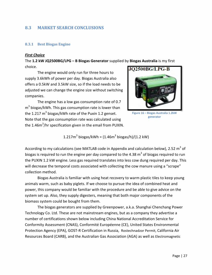
First Choice
The 1.2 kW JQ2500BG/LPG – B Biogas Generator supplied by Biogas Australia is my first
choice.
The engine would only run for three hours to
supply 3.6kWh of power per day. Biogas Australia also
offers a 0.5kW and 3.5kW size, so if the load needs to be
adjusted we can change the engine size without switching
companies.
The engine has a low gas consumption rate of 0.7
m3 biogas/kWh. This gas consumption rate is lower than
the 1.217 m3 biogas/kWh rate of the Puxin 1.2 genset.
Note that the gas consumption rate was calculated using
the 1.46m3/hr specification given in the email from PUXIN.
1.217m3 biogas/kWh = (1.46m3 biogas/h)/(1.2 kW)
According to my calculations (see MATLAB code in Appendix and calculation below), 2.52 m3 of
biogas is required to run the engine per day compared to the 4.38 m3 of biogas required to run
the PUXIN 1.2 kW engine. Less gas required translates into less cow dung required per day. This
will decrease the temporal costs associated with collecting the cow manure using a “scrape”
collection method.
Biogas Australia is familiar with using heat recovery to warm plastic tiles to keep young
animals warm, such as baby piglets. If we choose to pursue the idea of combined heat and
power, this company would be familiar with the procedure and be able to give advice on the
system set up. Also, they supply digesters, meaning that both major components of the
biomass system could be bought from them.
The biogas generators are supplied by Greenpower, a.k.a. Shanghai Chenchang Power
Technology Co. Ltd. These are not mainstream engines, but as a company they advertise a
number of certifications shown below including China National Accreditation Service for
Conformity Assessment (CNAS), Conformité Européenne (CE), United States Environmental
Protection Agency (EPA), GOST‐R Certification in Russia, Rostechnadzor Permit, California Air
Resources Board (CARB), and the Australian Gas Association (AGA) as well as Electromagnetic
Figure 16 – Biogas Australia 1.2kW generator

Page | 28
Compatibility (EMC) . In light of these certifications, this engine has a stronger guarantee of being
safer than the ACME engine.
Second Choice
The AM1500BG 1kW biogas generator set by Wuhan
Acme Agro‐Tech Co. was chosen to be the second best
genset candidate based on its low price and low gas
consumption rate. It has an investment cost of €320
and a gas consumption rate of 0.7m3 biogas/kWh
according to a quote supplied by the manufacturer
upon email request. Just like for Biogas Australia, the
low gas consumption rate makes it considerably more
desirable than the PUXIN engine. The generator is
tailored for biogas only and outputs a current at 230V
and 50Hz, which is the standard for Kenya; thus the electricity generated should be highly
compatible with the appliance loads there. Lastly, ACME produces a 2kW and 3kW version of
this generator set, so if the electricity load on the biogas system needs to be increased in the
future we can easily do so.
Note: Shengdong new Energy Technology Co. (€435), Guangzhou Dingfeng (€600), and Juangsu
Hopepower New Energy have prices and gas consumption rates comparable to ACME, but they
were not ranked for various reasons.
Shengdong new Energy Tech was not ranked because the user manual provided for the
generator set seemed inadequate. However, I do not know what the user’s manual for the
ACME engine will look like. Also, ACME offers biogas digesters suggesting that the company is
more familiar with the entire biomass system.
I did not get a reply from Guangzhou Dingfeng Machinery Co. nor Juangsu Hopepower New
Energy, therefore this engine was not ranked. If I could not get a response, then it might be
difficult working with the company in the future. Both Kristel and I have been in contact with
Leo Liu from ACME and while I did not find that many safety standard certificates, they do have
many manufacturing/economic/business certificates and awards unlike Shengdong who had
none available.
Third Choice
Figure 17 – ACME 1kW Biogas Generator
Page | 29
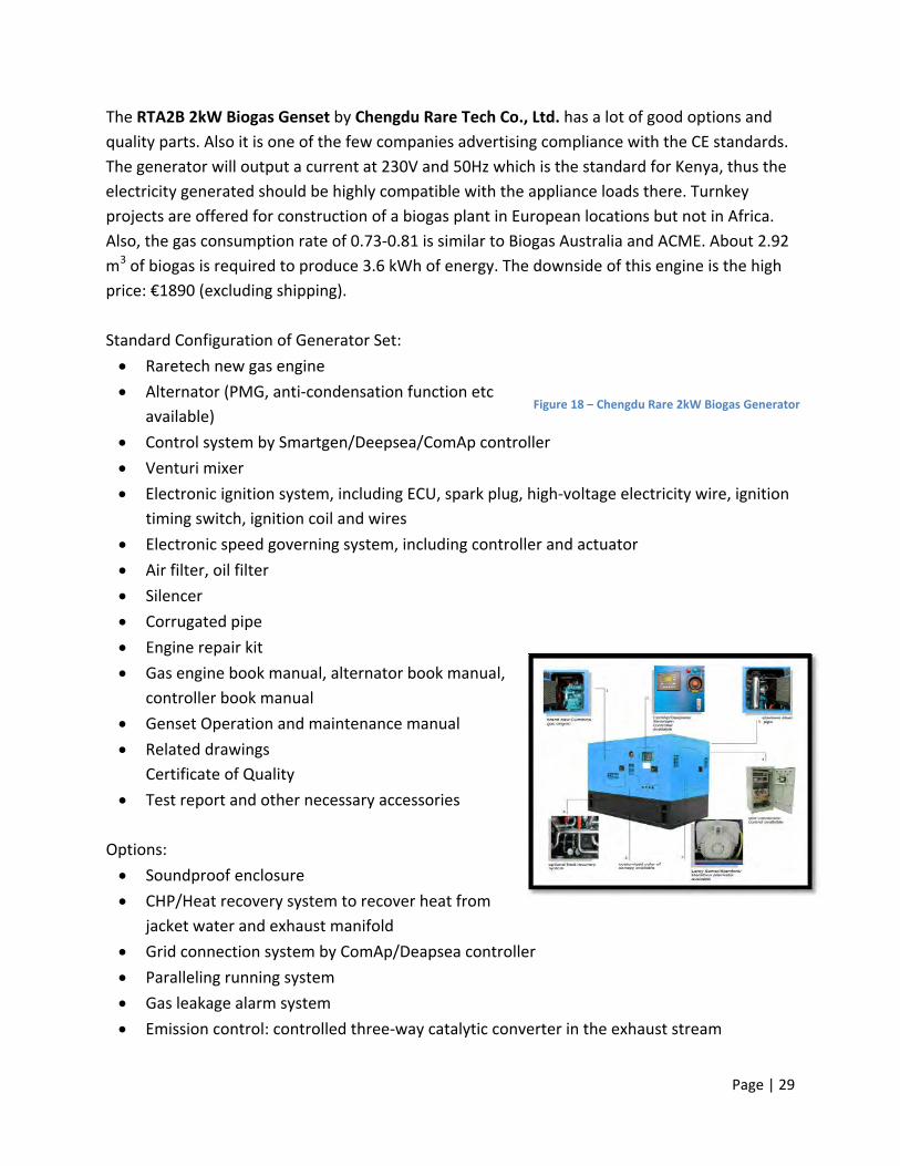
The RTA2B 2kW Biogas Genset by Chengdu Rare Tech Co., Ltd. has a lot of good options and
quality parts. Also it is one of the few companies advertising compliance with the CE standards.
The generator will output a current at 230V and 50Hz which is the standard for Kenya, thus the
electricity generated should be highly compatible with the appliance loads there. Turnkey
projects are offered for construction of a biogas plant in European locations but not in Africa.
Also, the gas consumption rate of 0.73‐0.81 is similar to Biogas Australia and ACME. About 2.92
m3 of biogas is required to produce 3.6 kWh of energy. The downside of this engine is the high
price: €1890 (excluding shipping).
Standard Configuration of Generator Set:
Raretech new gas engine
Alternator (PMG, anti‐condensation function etc
available)
Control system by Smartgen/Deepsea/ComAp controller
Venturi mixer
Electronic ignition system, including ECU, spark plug, high‐voltage electricity wire, ignition
timing switch, ignition coil and wires
Electronic speed governing system, including controller and actuator
Air filter, oil filter
Silencer
Corrugated pipe
Engine repair kit
Gas engine book manual, alternator book manual,
controller book manual
Genset Operation and maintenance manual
Related drawings
Certificate of Quality
Test report and other necessary accessories
Options:
Soundproof enclosure
CHP/Heat recovery system to recover heat from
jacket water and exhaust manifold
Grid connection system by ComAp/Deapsea controller
Paralleling running system
Gas leakage alarm system
Emission control: controlled three‐way catalytic converter in the exhaust stream
Figure 18 – Chengdu Rare 2kW Biogas Generator

Page | 30
Remote genset running online monitor
Automatic transfer switch (ATS)
Maintenance‐free storage battery 12V DC for starting and power supply control
Battery charger 12V DC
Latest Design Choice
The most recent biomass system design proposal suggests the use of a PX‐BG 1.2 kW Biogas
Genset from Shenzhen Puxin Technology Co. Ltd. This engine has an appealing size and price
but the gas consumption rate of 1.2 m3/kWh makes it less desirable. As aforementioned, at this
rate 4.38 m3 of biogas is required to run the engine for 3 hours per day.
8.3.2 BestAnaerobicDigester
Best Value
If either the 1.2 kW Biogas Australia genset or the 1kW ACME genset is used to reach the target capacity (3.6 kWh/day), then the accompanying digester must produce at least 2.52 m3 of biogas. The DIY 16 m3 PVC Digester Kit from Biogas Australia reports the highest gas production rate of 6.2 m3 biogas/day. At this rate, the digester would
be able to produce an adequate supply of biogas to keep the genset running for up to about 7‐8 hours a day.
Biogas Australia Genset
(4 m3 biogas produced/day) x [(0.7 m3/kWh) x (1.2kW)]‐1 = 4.7 hours/day (5.6 kWh)
(6.2 m3 biogas produced/day) x [(0.7 m3/kWh) x (1.2kW)]‐1 = 7.4 hours/day (8.8 kWh)
ACME Genset
(4 m3 biogas produced/day) x [(0.7 m3/kWh) x (1 kW)]‐1 = 5.7 hours/day (4 kWh)
(6.2 m3 biogas produced/day) x [(0.7 m3/kWh) x (1 kW)]‐1 = 8.8 hours/day (8.8 kWh)
If it is only run for the 4 hours that we are aiming for right now, then the excess biogas
produced that day will amount to a full day’s supply that could be used during peak hours. The
6.2 m3 production rate is most likely an overestimate of a maximum production under ideal
Figure 19 – Biogas Australia 16m3 Digester
Page | 31
conditions, so if the rate turns out to be lower, suppose 4 m3, the amount of biogas produced
will still be adequate for the day’s supply.
This digester also has a fairly simple installation process and an adequate kit. The kit
includes the double membrane PVC biogas digester, pipes and fittings, biogas booster pump
(electric), water separator, biogas purifier, safety relief valve, and single burner stove. The stove
is not needed, so we can request a reduction in the price to have it omitted from the standard
kit. They also offer a consultation service—at a cost—to help you to estimate the parameters of
your biomass system so that you can choose the appropriate digester size out of the range
offered: 6 m3 to 50 m3. The quote of €2300 includes the 16 m3 soft digester with all fittings
water separator, biogas purifier, and booster pump, a 20m3 biogas storage bag (required for
genset use), 1 1.2kW biogas genset (manual start), and sea freight to Mombassa, Kenya.
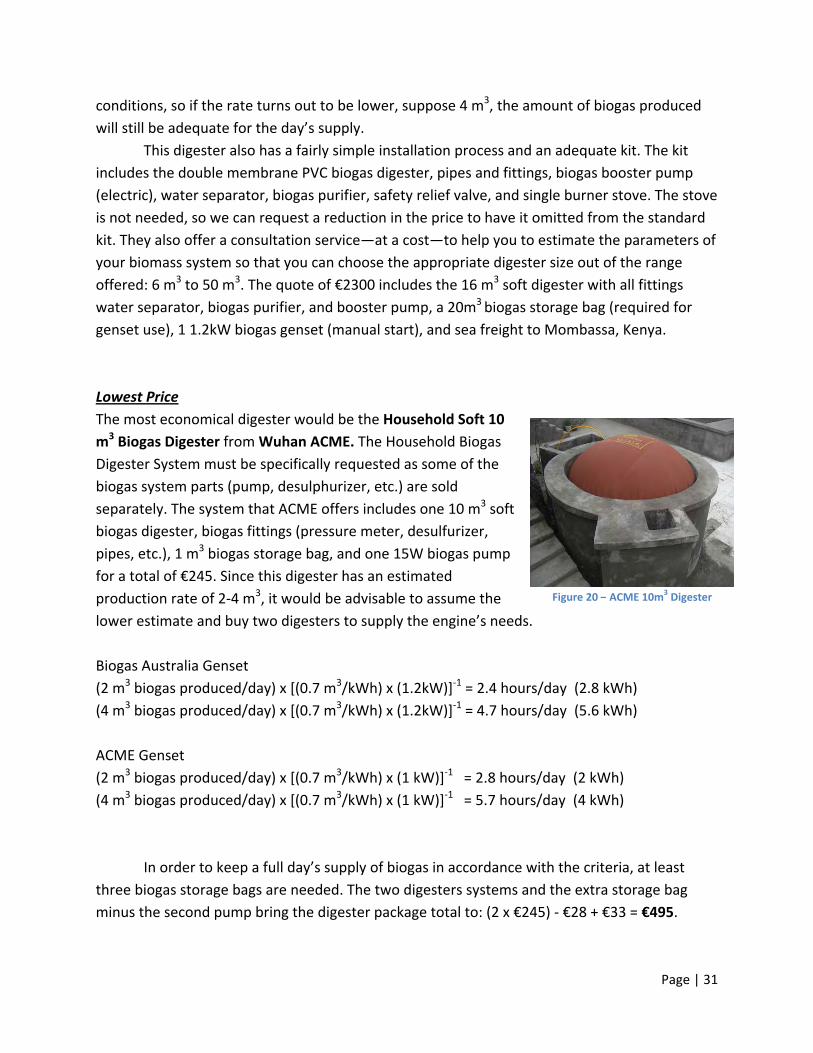
Lowest Price
The most economical digester would be the Household Soft 10
m3 Biogas Digester from Wuhan ACME. The Household Biogas
Digester System must be specifically requested as some of the
biogas system parts (pump, desulphurizer, etc.) are sold
separately. The system that ACME offers includes one 10 m3 soft
biogas digester, biogas fittings (pressure meter, desulfurizer,
pipes, etc.), 1 m3 biogas storage bag, and one 15W biogas pump
for a total of €245. Since this digester has an estimated
production rate of 2‐4 m3, it would be advisable to assume the
lower estimate and buy two digesters to supply the engine’s needs.
Biogas Australia Genset
(2 m3 biogas produced/day) x [(0.7 m3/kWh) x (1.2kW)]‐1 = 2.4 hours/day (2.8 kWh)
(4 m3 biogas produced/day) x [(0.7 m3/kWh) x (1.2kW)]‐1 = 4.7 hours/day (5.6 kWh)
ACME Genset
(2 m3 biogas produced/day) x [(0.7 m3/kWh) x (1 kW)]‐1 = 2.8 hours/day (2 kWh)
(4 m3 biogas produced/day) x [(0.7 m3/kWh) x (1 kW)]‐1 = 5.7 hours/day (4 kWh)
In order to keep a full day’s supply of biogas in accordance with the criteria, at least
three biogas storage bags are needed. The two digesters systems and the extra storage bag
minus the second pump bring the digester package total to: (2 x €245) ‐ €28 + €33 = €495.
Figure 20 – ACME 10m3 Digester

Page | 32
Using multiple digesters in the system presents the problem of consistency and physical
integration. First, it will be difficult to assure that the two digesters are loaded in the exact
same way, so the percent methane of the biogas from one of the digesters might be different
than the biogas from the other digester. If this is the case, then the mixed gas flowing into the
genset could cause engine problems. Second, connecting the two digesters to two separate
bags and biogas pumps and then to one engine means multiple pipe connections and more
chances for biogas leaks. Also, it might not be feasible for the engine to accept biogas from
both pumps at the same rate if the pipes from the two pumps are connected to the single pipe
leading into the pump. In reality, having two digesters may not present problems, but it will
most likely require additional effort to prepare the system.
Latest Design Choice
The Chongqing Xinshui Machine Manufacture Series H H15‐Q80
15m3 PVC digester was the digester of choice in the latest
polygeneration system design proposal. It is a PVC tube type
digester that produces 2 m3 of biogas per day. Two digesters would
be needed to meet the demands of the ACME engine for a total
price of €772. This price includes the biogas digester, 25 m of
pipeline, the joint, gas nozzle, safety valve, gas‐water separate,
biogas desulfurizer, PVC hoop, booster pump, and pipeline control
switch. Having all of the fittings included with the digester ensures that the pieces will fit
together properly. The downside to choosing this digester is the need for two digesters. Also,
they do not provide a biogas storage bag in the package, so this will have to be purchased
separately. Chongqing Xinshui Machine Manufacture Company was awarded a Certificate of
Conformity of Quality Management System Certification from CNAB for the years 2004‐2010.
8.3.3 BestDigester‐EnginePairs**
**Please note that Biogas Australia is the only company to include the shipping cost in the price.
#1 Biogas Australia: €2300 incl. shipping to Mombassa
Includes: Biogas Australia digester & fittings, H2O separator, H2S scrubber, booster pump, 1
20 m3 storage bag, 1.2 kW engine
Total Package Size and Weight: 0.93 m3 and 103 kg
Pros: Both the digester and engine are supplied by the same company which assures that
the pipes will all be included in the kit and they will all fit properly. They also offer a 0.5 kW,
1.2 kW, and 3.5 kW engine. Consultation service (at a cost) to help you with digester sizing.
Figure 21 – Chongqing Xinshui 15m3 Digester

Page | 33
Cons: The engine is not actually manufactured by Biogas Australia so it may take longer to
get spare parts if needed. Large package size. Short lifetime (5 years).
Other Options: Biogas Australia is able to supply absorption chillers which utilize the heat
from the exhaust system of a genset to provide refrigeration. The genset can also be fitted
with a CHP unit.
#2 ACME: €815 excl. shipping
Includes: 2 digesters & fittings, H2S scrubber, pump, 3 ACME 1 m3 biogas storage bags, 1
kW engine
Total Package Size and Weight: 2*(600x300x400) + (610x450x470) = 0.28 m3 and 93 kg
Pros: All parts are manufactured by ACME. Lowest investment cost.
Cons: You need 2 digesters so you will have to make some alterations in order to connect
two digesters with one engine.
#3 Chongquing digester + ACME 1 kW engine: €1194 excl. shipping
Includes: 2 digesters & fittings, H2O separator, H2S scrubber, pump, 2 1m3 ACME storage
bag, 1 kW engine
Total Package Area: 2*(600x300x400) + (610x450x470) = 0.27 m3 and >43 kg (engine weight
only, digester size not provided)
Pros: Second cheapest option.
Cons: Products are from 2 separate companies so alterations will most likely be needed. 2
digesters required.
Latest Configuration = Chongquing digester + PUXIN 1.2 kW engine: €1905 excl. shipping
Includes: 3 digesters & fittings, H2O separator, H2S scrubber, pump, 1 storage bag, 1.2 kW
engine
Total Package Area: 3*(600x300x400) + (620x480x480) = 0.36 m3 and >43kg (engine weight)
Pros: 10 year lifetime
Cons: Second most expensive. Products from 2 separate manufacturers and 3 digesters
needed, so alterations will most likely be necessary.
9 SYSTEMINTEGRATIONThis section outlines the integration of the Biogas Australia digester and engine into the
polygeneration unit. The integration requirements were suggested in the ‘WP2 – Subsystem
Integration Strategy’ report.

Page | 34
9.1 ElectricityStandardThe standard for Kenyan electrical appliances is 220‐240 V, 50Hz, and Type G British BS‐1363
electrical outlets. The Biogas Australia 1.2 kW JQ2500BG/LPG – B biogas generator is a single
phase brushless generator with an AC output at 50 Hz and 230 V. According to the integration
strategy in the WP2 report, the AC output should be at 240V, therefore, an alternator may be
needed to properly integrate this electrical system.
9.2 PackageSize According to the Subsystem Integration Report SELECT 2011, a standard container sized 6.1m x
2.44m x 2.6m (l x w x h) will be used. It can hold a net weight of 21600 kg. The digester package
size and weight was given to be 1100 x 900 x 800 mm and 53 kg, but the genset package size
was not provided. Based on the size and weight of the other 1‐1.2 kW engines that I found, the
size and weight of the Biogas Australia genset is estimated to be about 610 x 460 x 470 mm and
50 kg. This makes the total package size 0.93 m3 and 103 kg. The weight is not significant
compared to the gross weight that the container can hold, but this package will take up about
2.4 % of the total volume.
9.3 SafetySpecial caution should be taken with regards to the following:
Biomass and biogas storage
Biomass feeding and handling (Use gloves)
Engine high temperature
Conditioning of gas including gas cleaning and safety valve
Control systems
Electrical configuration
The operational manuals provided by the suppliers will contain safety information that should
be included in the overall safety guidelines for the container.
9.4 Environmental,safetystandardsandlicenseThe biomass system should be configured such that it complies with all necessary safety and
environmental standards. These standards will apply to engine emissions, digester emissions,
safety of electrical configuration, and the quality of the digester effluent (solid waste). Since
the container will be developed in Sweden and tested in Kenya, both Swedish and Kenyan

Page | 35
emissions and environmental standards should be met. Some of the requirements will most
likely be developed by the following governing bodies:
Kenya Ministry of Environment, Water and Natural Resources
<http://www.environment.go.ke/>
Kenya Solid Waste Managements
<http://www.unep.or.jp/ietc/GPWM/data/T2/IS_6_P_PolicyAndRegulations_Nairobi.pdf>
Swedish Environmental Zones regulation
<http://www.dieselnet.com/standards/se/zones.php#intro>
There are also general engine generator guidelines developed by China National Accreditation
Service for Conformity Assessment (CNAS), Conformité Européenne (CE), United States
Environmental Protection Agency (EPA), GOST‐R Certification in Russia, Rostechnadzor Permit,
California Air Resources Board (CARB), and the Australian Gas Association (AGA). If the engine
complies with these, then it is more likely that they will comply with the Kenyan and Swedish
environmental and electrical standards.
9.5 InstallationThe system should be set up according to the instructions manual included with the kit
provided by Biogas Australia. There are also a number of other manuals outlining the
construction of polyethylene tube type biomass digesters that would be valuable
supplementary material for the installation, including the Cameroon DIY manual (Harris, 2008)
and the Honduras Gas Biodigester Information and Construction Manual for Rural Families by
FUCOSOH (Brown, 2004).
The main set up of the Biomass Australia system is pictured in Figure 22. The biogas safety
equipment, air water separator, biogas desulfurizer, pump, storage bag, and engine can be kept
inside of the container, while the digester will be set up outside of the container. The demo
container at KTH has the biogas system sectioned off from the rest of the container by a wall so
that the systems operator will not be breathing in the fumes from the engine. This set up
should be utilized in the next prototype for the same reasons. A hole will have to be cut into the
door so that the biogas tube can be connected from the gas holder (outside) to the biogas
pump (inside).

Page | 36
Figure 22 – Biogas Australia digester kit and engine set‐up
9.6 AdequateManualThe digester purchased will contain a manual outlining the construction of that specific
digester. For the all‐inclusive manual that will be created for the polygeneration unit, the
authors should consult a few other manuals for polyethylene tube type digesters for extra tips
and advice. There were a number of said manuals found during this project and previous work
by the research team including the Cameroon DIY manual (Harris, 2008) and the Honduras Gas
Biodigester Information and Construction Manual for Rural Families by FUCOSOH (Brown,
2004). The following needs to be addressed in the final manual:
Connecting the biogas tube from the biodigester to the biogas storage bag to the
biogas pump to the engine
How to mix the manure and water
How to properly load the digester
How long it will take before biogas production can be expected
Gas pressure required by the generator set
9.7 MonitoringBiogasProduction There is a Matlab script for anaerobic digestion optimization found during the review that
might be available for purchase (Gaida 2011). The value of purchasing the Matlab Toolkit can be
Air Water Separator Biogas Desulfurizer
Biogas Engine Generator
Biogas
Storage Bag
Biogas Safety Equipment
Conical Inlet
Orifice
Biogas
Digester
SwitchPump
Feed Outlet
Discharge Pipe Feed Pipe
Discharge Valve
Feed
Inlet

Page | 37
determined once more research is done on the unit functionality. In the meantime, the script
created as part of this project can be used to do rough estimations of the amount of manure
needed given the desired amount of electricity per day.
10 ANAEROBICDIGESTIONCALCULATIONSandPARAMETERJUSTIFICATIONS
A Matlab code was written that estimates the amount of manure and the number of cows
needed to run the biogas engine. This script was designed to be flexible so that if some
parameters of the systems are changed in the future the appropriate adjustments can be made
in the code as well. The user can get a sense of the amount of resources required for a certain
electrical capacity by going into the script and adjusting the desired electrical capacity (‘Target’)
from 3.6kWh to the new quantity. In this code, I tried to take into account the percentage of
volatile solids in the manure, type, breed, and live weight of the cows, and the gas consumption
rate of the engine.
10.1 MotivationandExplanation
Not all of the manufacturers provided the hydraulic retention time or organic loading
rates of their digesters which are needed to determine the amount of dung and number of
cows needed to supply the digester. Since this information was not readily available, I tried
bypassing the digester data by determining the amount of manure needed based on the gas
production per kilogram of volatile solids added to the digester. Further research should be
done to develop a reliable calculation that outputs the digester volume required given the
amount of biogas needed in a given day. A Matlab Toolkit for anaerobic digestion was located
but the author of the paper was not contacted and it is unclear whether or not the program is
available for purchase (Gaida 2011). It might be worthwhile to invest in the program because
customers will want biogas production estimates for their region. If there has not been enough
data collected for different climates, then it might be difficult to provide a satisfactory estimate
without a program.
10.2 Calculations
A combination of calculations and case study data was used to estimate the amount of manure
and the number of cows needed to run the biogas engine. The literature survey of the
anaerobic digestion process also informed the calculations needed to determine the amount of
dung and water required to run a biogas genset. The calculations were done using Matlab and
Page | 38
the code can be found in the Appendix. The calculations below explain the ‘Alternate’ portion
of the code that is based on the gas produced per unit of volatile solids degraded (Barker,
2001). The ‘Original’ calculations (not described below) are based on the biogas yield per cow
specification from the Kenyan Ministry of Agriculture.
The volume of biogas required to run the engine for the load of one day
Gas Required, m3 = (Gas Consumption Rate, m3/kWh) x (Target Capacity, kWh)
Total solids (dry matter) produced per cow. It is generally accepted that a ruminant produces
0.8% of its live weight as faecal dry matter in a day (Lekasi, Tanner, Kimani, & Harris, 2001)
TS per cow = 0.008 x (Live Weight, kg)
Calculate the amount of manure that a cow produces in one day.
Manure per cow, kg = (TS per cow, kg)/(TS content of cow manure)
Calculate the volume of biogas that can be expected from one cow.
Gas per cow, m3 = (TS per cow, kg) x (%VS in faecal DM) x (%VS degradation/100) x (Gas per kg
of volatile solids degraded in digester, m3/kg VS)
Number of cows required.
# Cows Required = (Gas Required, m3) / (Gas produced per cow, m3)
Calculate the total amount of manure required to run the engine.
TS Required, kg = (TS per cow, kg) x (# Cows Required)
Manure Required, kg = (TS Required, kg) / (TS content of cow manure)
The amount of water required to dilute the manure to the optimal solids content of the slurry.
H2O Required, kg = [(TS Required, kg)/(OSC)] – (Manure Required, kg)
Total amount of slurry that must be added to the digester.

Page | 39
Slurry Required, kg = Manure Required, kg + H2O Required
10.3 ParameterJustifications
Here I have defined a number of parameters of a biomass digestion and biogas engine system.
Most of the parameters deal with the biomass anaerobic digestion process itself. It is very
important that each parameter be carefully chosen to optimize the system productivity, but
they should also be chosen to optimize the cost and economic aspects of the project. The
feedstock parameters play a crucial role in determining the biogas production per day. For this
reason, I examined the types of cows, different feedstock combinations, and types of biomass
reactor systems in depth. Total volatile solids content and total solids content are two of the
most important feedstock parameters needed to design the system.
Type of Cow = Friesian dairy cow The most common cattle breed in Kenya is the Friesian dairy cow. Type of cow must be taken
under consideration because dairy cow manure has a much lower percentage of total solids –
and so volatile solids as well – compared to beef (Barker, 2001; Gichohi, 2009).
LiveWeight = 500 kg Live weight depends upon the type of cow. Other common cows in Kenya include dairy cows Friesian, Ayrshire, Guernsey, and Jersey. These dairy cows weight 500‐550kg, 450kg, 400kg, and 350kg respectively. Since Friesian cows have a weight ranging from 500‐550kg, I chose to use the lower limit to account for the other cows in Kenya (Ouda, 2011).
TSC = 0.4 Total solids (also dry matter) content of cattle faeces is 40% and that of small ruminants is 50% (Lekasi et al., 2001). GasVSD = 0.6861 m3 biogas/kg VS This value for gas produced per kilogram of VS degraded was used in the James Barker calculations for a 1400lb Dairy Cow (Barker, 2001). GasCow = 0.96 m3 biogas/cow/day This value was taken from data compiled by the Kenya Ministry of Agriculture (Gichohi, 2009). I chose to use the data for the Garissa district in Kenya because it has an arid climate similar to that of the proposed Lodwar test site. It also seemed like the most rural option because it has a 50% poverty rate and 39.7% literacy level, and they are the farthest from a major city.

Page | 40
VSDPerc = 35% From manipulation of James Barker calculations I found that a value of 35% was used for the percentage of VS that was degraded out of the total amount of VS added to the digester (Barker, 2001). Volatile solids degradation is estimated to be 40% for the digestion of dairy manure (Wilkie, 2005). I went with the smaller number because it is better to overestimate the amount of manure required than underestimate it. VSTS = 0.76 This value represents the percentage of VS in TSC of manure. It is based on swine manure data from a study by Clemson University. I divided the volatile solids found in swine manure, 4.5 lb/AU/day, by the total solids found in swine manure, 5.9 lb/AU/day. This resulted in a percent volatile solids of about 76% (Chastain, Camberato, & Albrecht, 2001). OSC = 0.08 Optimal solids content is 6‐8% for maximum volatile solid degradation (Singh, 1971; Rajendran et al., 2012). HRT and OLR
In the literature study, the hydraulic retention time and organic loading rate were reoccurring
parameters (Nasir et. al, 2012). Thus, I tried using them to calculate the digester volume but
without knowing the organic loading rate of the digester, I was not able to define a satisfactory
relationship between the required amount of slurry, the HRT, and the necessary digester
volume. Since only two manufacturers provided me with an organic loading rate and the rates
of the studies in (Nasir et al., 2012)AD of LM varied over such a large range (1.9 – 20 kg VS/m3
digester capacity/day), I did not feel comfortable estimating this parameter and using it to
estimate the appropriate digester capacity. In a study referenced in Nasir et al., the methane
yield did not significantly increase upon increasing the HRT from 20 days to 30 days, leading to
the conclusion that HRT is not a significant operational parameter (Alkaya, Erguder, & Demirer,
2010). The HRT is actually dependent upon the optimal loading rate and how quickly the slurry
moves through the digester. For suspended growth systems, an HRT of at least 10‐15 days is
required for adequate bacteria growth. Based on the study and the correlation between the
HRT and the OLR, I decided not to use either of the two parameters and to determine the
necessary digester capacity directly based on the gas production rates that the manufacturers
provided me with. The gas production rates and corresponding capacities can be found in excel
spreadsheet in the (Appendix—Market Search: Biomass Digesters).
Reference (Alkaya et al., 2010)

Page | 41
11 FUTURECONSIDERATIONSandINVESTIGATION The biogas digester and engine candidates were made based on the criteria outlined by POY Group A in their final report. The two candidates are the best for the next prototype in the Kenyan rural village but many other considerations should be taken when selecting the final biogas system. Insofar the intended use of the polygeneration project has been to provide rural electrification as well as serve as an emergency energy module after natural disasters. The biogas system chosen in this project might be too permanent to be effective in a natural disaster situation. There are a number of portable biodigester systems that could work, but it would still take a few days before a sufficient amount of biogas could be produced to run the biogas genset. A gasoline engine would be the most efficient in this case, though it would go against the goal for the unit to be 100% renewable.
11.1 DifferentReactorSystems
An attached growth system should be considered for its low hydraulic retention time and ability
to quickly digest a larger amount of substrate than the suspended growth system. The up flow
anaerobic sludge blanket (UASB) and anaerobic filter (AF) reactor are just two examples of
attached growth reactor systems that might be suitable for large‐scale dairy farms with flushed
manure systems (Nasir et al., 2012). They would also be useful if there was a very high demand
for fertilizer because then more output slurry would be needed per day.
Below is a list of dairy farms that have Friesian cows. The farms would be good sites to test the
polygeneration unit on a larger‐scale operation. (Ouda, 2011)
1. Manera (Delamere Estates), Naivasha
2. KARI Naivasha, PO Box 25 Naivasha
3. KAR Lanet, PO Box 1275, Nakuru
4. Agricultural Development Corporation (ADC) Katuke Complex, PO Box 1392‐30200
Kitale
5. Makongi Farm, PO Box 1320‐30100 Eldoret
6. Kisima Farm, PO Box 19‐ 20107 Njoro
7. Gogar Farm PO Box 6‐201080 Rongai
8. University of Nairobi Farm PO Box 29053‐10202 Kabete
9. Sanctuary Farm PO Box 244‐20177 Naivasha
10. Marimba Farm PO Box 32 Meru
11. ADC Olngatongo PO Box 680‐30200 Kitale
12. Gicheha Farm, PO Box 236 Ruiru

Page | 42
11.2 DifferentTypesofFeedstock
The compilation put together in the review by Nasir et al. (2012), the biogas yield for cow
manure Is lower than the yield for swine or chicken. The lower biodegradability is due to the
high amount of inorganic compounds and fibers left undigested after exiting the cow digestion
system. According to Table 1 in a study by Nasir et al, pig and swine manure have resulted in a
higher percentage of CH4 in the biogas. Also, they have much shorter hydraulic retention times
(HRT) which minimize reactor volume and ensure thorough mixing with an effective transfer of
organic material for the active microbial biomass.
The conclusion of the review held that co‐digestion improves biogas yield and
bioreactor performance. Several studies concluded that co‐digestion of manure with easily
biodegradable organic waste yields a higher methane content (Nasir et al., 2012; Rajendran et
al., 2012; Boe, 2006). Based on this conclusion, and the results of the review, the team should
consider finding a feedstock supply that combines animal manure and perhaps human
excretion, food scraps, or some type of plant clippings. Please note that mixing hog and chicken
waste was not very effective and somewhat detrimental to the anaerobic digestion process
(Nasir et al., 2012).
According to data collected by the Kenya National Bureau of Statistics (2010) goats, pigs, camels
are other available livestock in Kenya.
11.3 IncentivizingDungCollection
If the cows are free range, then collecting the dung will be challenging. If the system is for a
couple of households, who is to say that one family will make sure to collect all of the dung
while other families will fail to contribute dung yet continue to reap the benefits of electricity
and clean water? Either there should be someone hired to collect dung, or people who input
dung should get a discount on their electricity. They could also get an end of the month refund
or something comparable based on how many kilograms of dung they contribute. You would
only need a scale to check the weight of the feedstock and the person manning the container
would keep records so that at the end of the month refunds could be awarded to families who
contribute to the feedstock. This might help avoid the Tragedy of the Commons. On the other
hand, it might be that the community members do not mind working together for the
electricity and clean water generation.
If, however, the dung comes from cows that are on a large scale farm, then a flush
system might be employed. If this is the case, then the feedstock supply will only depend on
one large farm as opposed to collection by 25 different households.

Page | 43
11.4 UsesforOutputslurry
The two main questions for the output slurry are:
1) What should be done with it? and
2) Who will be responsible for removing it?
In resource‐poor regions of East Africa, cattle are more valuable for their manure and strength
than their milk or meat because the dung is a nutrient rich fertilizer. Since fertilizer can be
expensive for poorer families, there is a demand for a cheaper option in lower‐socioeconomic
regions. According to case studies of plastic tube digesters in Honduras (Brown, 2004) and
household biogas digesters (Rajendran et al., 2012), the output slurry of the PTD is a clean,
organic fertilizer that can be used for crop production. Burke 2001 suggests that the output
slurry fertilizer can be sold to the public, nurseries, or other crop producers for some
profit(Burke, 2001).
The KTH field team may want to see how many farms there are in the area and if they
use manure as fertilizer. If there is a high demand, then sale of the output slurry might be a
viable option and the profit could go toward the polygeneration unit maintenance. If someone
is hired to man the unit, then he or she can sell the manure to local farmers. The farmers would
have to come to the unit bringing their own containers to transport the slurry back to their
farms. The reactor would get extremely messy if there was not a guaranteed demand for
fertilizer.
Another option would be to have the sludge treated as municipal solid waste and disposed of at
a nearby municipal waste unit. If the test region has a centralized sewage system in place and
there is not a high enough demand for the slurry as fertilizer, then this could be a good option.
11.5 Biodieselvs.Biogas
Biological waste from sugar cane, corn, etc. can be used to produce biodiesel. Biodiesel might
be more suitable than biogas for natural disaster circumstances. For natural disasters, it will
probably be necessary to transport the fuel in the container instead of producing it on site as is
the case for rural electrification. I do not know the dimensions, weight, or logistics of
transporting biodiesel or biogas, but it might be more cost effective and safer to transport
biodiesel. The digester would not be needed, which would leave more space in the container
for the fuel. If biodiesel proves to be more efficient than biogas, then this option should be
considered for emergency situations.
11.6 HeatRecovery

Page | 44
Heat can be recovered from the exhaust pipe of the biogas engine. It was previously discussed
as being used to heat the digester. This heat can also be used to provide central heating for
houses, heating for livestock stables, newborn incubation units, refrigeration, etc.
12 FURTHERRESEARCH
Study the electrical compatibility of the generator set with the load appliance. I am not versed
in enough electrical engineering to know which standards and requirements to look for in
generator systems so someone should make sure that the engine I chose complies with the
safety standards, from an electrical engineering perspective.
When you do field tests in Kenya, you will have to experiment with feedstock, loading rate, and
water dung ratios to determine the maximum biogas production rate. There is only so much
you can gain from calculations. In case studies of PTD installments in Kenya, Bolivia, Honduras,
etc. the study concluded that failure of digesters is largely due to lack of proper loading (Brown,
2004). Thus, the operational manual for the polygeneration unit should have as detailed as
possible instructions on how to properly load the digester and how long people can expect to
wait before seeing steady biogas production.

Page | 45
WORKSCITED
Alkaya, E., Erguder, T. H., & Demirer, G. N. (2010). Effect of operational parameters on anaerobic co‐digestion of dairy cattle manure and agricultural residues: a case study for the Kahramanmaras region in Turkey. Engineering in Life Sciences, 10, 552‐559.
Atkins, Melea, Fuchs, Miriam, Hoffman, Adam, & Wilhelm, Natalie. (2008). Plastic Tubular Biogas Digesters: A Pilot Project in Uru, Kilimanjaro, Tanzania. Rhode Island, USA: Project Assida.
Barker, James C. (2001). Methane Fuel Gas from Livestock Wastes A Summary. Water Quality & Waste Management. North Carolina Cooperative Extension Service. Retrieved from http://www.bae.ncsu.edu/programs/extension/publicat/wqwm/ebae071_80.html
Boe, Kanokwan. (2006). Online monitoring and control of the biogas process. (Ph. D.), Technical University of Denmark, Denmark. Retrieved from www.er.dtu.dk
Brown, Laura. (2004). Gas bio‐digester Information and Construction Manual For Rural Families: Fundación Cosecha Sostenible Honduras.
Budiyono, Widiasa, I. N., Johari, S., & Sunarso. (2010). The Kinetic of Biogas Production Rate from Cattle Manure in Batch Mode. International Journal of Chemical and Biological Engineering, 3(1), 39‐44.
Burke, Dennis A. (2001). Dairy Waste Anaerobic Digestion Handbook: Environmental Energy Company.
Cattle Breeds. 2013, from http://kenya.thebeehive.org/en/content/881/2090
Chastain, John P., Camberato, James J., & Albrecht, John E. (2001). Nutrient Content of Livestock and Poultry Manure: Clemson University.
Gichohi, Peter. (2009). Analysis of the Market Potential for Domestic Biogas in Rural Kenya: Kenya Ministry of Agriculture and EU‐GTZ Biogas Promotion.
Harris, Paul. (2008). DIY Poly Digester.
Labatut, Rodrigo A., & Gooch, Curt A. (2012). Monitoring of Anaerobic Digestion Process to Optimize Performance and Prevent System Failure. Got Manure Conference Proceedings.
Leggett, Jeannie, Graves, Robert E., & Lanyon, Les E. Anaerobic Digestion: Biogas Production and Odor Reduction from Manure (A. a. B. Engineering, Trans.): Pennsylania State University College of Agricultural Sciences.
Page | 46
Lekasi, J. K., Tanner, J. C., Kimani, S. K., & Harris, P. J. C. (2001). Manure Management in the Kenya Highlands: Practices and Potential (Second ed.). Kenilworth, UK: Henry Doubleday Research Association.
Lyberatos, G., & Skiadas, I. V. (1999). Modelling of Anaerobic Digestion ‐ A Review. Global Nest: The International Journal, 1(2), 66‐76.
Marchaim, Uri. (1992). Anaerobic processes, plant design and control Biogas processes for sustainable development. Rome, Italy: Food and Agriculture Organization of the United Nations.
Matiri, F. M., & Kiruiro, E. M. (2009). The Impacts of Plastic Tube Digester (PTD) Technology at the household level: A Case Study of Central Kenya Highlands.
Muli, M. B., & Saha, H. M. Characterization of Readily Available Organic Manures in Coastal Kenya Natural Resource Management. Mtwapa, Kenya: Kenya Agricultural Research Institute.
Nasir, Ismail M., Mohd Ghazi, Tinia I., & Omar, Rozita. (2012). Anaerobic digestion technology in livestock manure treatment for biogas production: A review. Engineering in Life Sciences, 12(3), 258‐269. doi: 10.1002/elsc.201100150
Ouda, Jack. (2011). Cattle breeds and Breeding. 2013
Promoting BIogas Systems in Kenya: A feasibility study. (2007) Biogas for Better Life: ETC Group.
Rajendran, Karthik, Aslanzadeh, Solmaz, & Taherzadeh, Mohammad J. (2012). Household Biogas Digesters—A Review. Energies, 5(12), 2911‐2942. doi: 10.3390/en5082911
Singh, Ram Bux. (1971). Biogas Production.
Syed, Anas, Gupta, Arjun, Lykissa, Iliana, George, Johannes, Hartl, Judith, Sucipto, Juli, . . . Laux, Tillmann. (2013). Electricity and Water Supply in Developing Countries (S. P. o. t. Year, Trans.): Royal Institute of Technology.
Wilkie, Ann C. (2005). Anaerobic Digestion of Dairy Manure: Design and Process Considerations. Dairy Manure Managment: Treatment, Handling, and Community Relations, (NRAES‐176). Natural Resource, Agriculture, and Engineering Service, Ithaca, NY.
Page | 47
APPENDIX
AppendixA–ListOfSpecificationsRequestedOfTheManufacturerBiogas Genset
a) Rated power (Boe) b) Part Load Efficiency c) Gas consumption (m3/kWh) d) Biogas Conditions for the genset (Required methane content, %) e) Lifetime (years) f) Dimensions (mm x mm x mm) g) Weight (kg) h) Inlet pressure (kPa) i) AC or DC? j) Phase (single or three) k) Speed (rpm) l) Rated Voltage (V) m) Rated Current (A) n) Frequency (Hz) o) Shipping time p) Cost; Is it possible to buy a single genset?
Biogas Digester
a) Gas production (m3/day) b) Methanization Rate/Methane Content c) Capacity (m3) d) Lifetime e) Temperature it can withstand f) Optimal Feedstock (rice, corn husks, cow dung, etc.) g) Water‐Dung Ratio h) Hydraulic Retention Time i) Organic Loading Rate j) Gas pressure k) Inlet/outlet diameter and diameter of biogas pipe l) Ease of installation (Technicians required? Moderate, difficult? How many people are
needed? How long will it take?) m) Safety: Fire resistant? Protection from rain needed? Easily punctured? UV resistant? n) Package size (mm x mm x mm) o) Package weight (kg) p) Maintenance cost q) Delivery time r) Price s) Other fittings:
a. H2S scrubber included? How much?

Page | 48
b. Gas storage bag: material, thickness, size, pressure, weight c. Piping d. Biogas pump: specifications and price for this
AppendixB–ComparisonofMostCommonDigestersinKenya

Page | 49
Company
Biogas Australia Pty Ltd
BiogasSA
(Biogas
South Africa)
ACME
Guangdoh
ng
Huizho
u Biogas
Ecofys
Biogas International
Shen
zhen
Puxin
Techno
logy Co. Ltd.
Samuchit Enviro
Tech Pvt Ltd
Mod
elDIY PV
C Digester kit
DIY Biob
ag (P
VC)
Digester Kit
Househ
old Soft Biogas
Digester
Serie
s M
M15‐K120
Serie
s H
H15‐Q80
Family
sized
digester and
plastic
bag digester
Plastic
Bag Digester
Flexi Biogas S
ystem
Portable Biogas
plant
ARTI Hou
seho
ld
Biogas Kit
Capacity (m
3)16
2010
1515
8 (0.55m
m
thickness)
––
21
Gas P
rodu
ction (m
3/day)
6.2 (rou
gh estim
ate)
4‐6
2‐4
32
1.2‐2.4m
3/day
(abo
ve 15°)
––
1.5
1
Price (EUR
)2300* (in
cl. Shipp
ing)
1382 ex works
168
3860
386*
76300
–
Lifetim
e (years)
510 (15 if covered)
1510
1010
––
Ease of Installatio
n
(Mod
erate, difficult)
1/2 day for 2
peo
ple
Simple; 1 wee
k for 1
brick layer and
5
labo
urers
––
–1/2 day for 2
peo
ple
Easy (0.5‐1day)
1‐2days
Retention Time (days)
–25
60–
–7‐15
––
Commen
ts: Fittings and
Accessories
Kit Include
s: Dou
ble
mem
brane PV
C biogas
digester, pipes and
fittin
gs, biogas b
ooster
pump (electric), water
separator, biogas
purifier, safety re
lief
valve, single burne
r
stove. *Price includ
es 1
16m3 digester with
fittin
gs, w
ater se
parator,
biogas purifier and
booster p
ump; 1 20m
3
biogas holde
r; 1 2kWh
biogas gen
set, manual
start; and shipping
to
Mom
bassa, Ken
ya.
Kit Include
s: 20m
3
PVC Bag, Gas pipe
and fittin
gs, digester
pipe
fittings &
valves, pressure
pump &de
sulfu
rizer,
moisture trap
&safety valve,
Owne
rs Manual w
ith
full installatio
n and
operation de
tail. (A
n
extra gas storage
back is not includ
ed
because the gas is
stored
in th
e actual
biob
ag)
Fittings and
pum
p no
t
includ
ed as in a kit, bu
t
they
are available for
purchase. (See 'Fittings'
tab)
* Price includ
es
fittin
g and pu
mp.
*Price includ
es
biogas digester,
pipe
line (25m
).
joint , gas nozzle,
safety valve, gas‐
water se
parater,
biogas
desulfu
rizer, PVC
hoop
, boo
ster
pump, pipeline
control switch
Digester package
includ
es digester
(cylindrical or
rectangular), 2
clam
ps, spe
cial
glue
, 0.3 m2 extra
PVC material, and 1
gas p
ipe.
Internal gas storage bag,
no se
cond
ary gas storage
need
ed
Includ
es: Flexi digester,
suscreen
micro
gree
nhou
se tu
nel
Ramtons W
hirlw
ind
Techno
logy 501 Dou
ble
Burner Stove, piping and
fittin
gs (u
p to 30m
/kit),
training
on mainten
ance
and repair
The
plant includ
es a
PUXIN portable
digester, a
desulfu
rizer, a gas
storage bag, a gas
pump, a so
lar
charger, as well as a
gas p
ipeline and
applicances
Alon
g with
the
SET kit, we
wou
ld have to
provide a plastic
tank
(one
common
ly used
for w
ater
storage). A
lso,
the biogas is
mainly used
for
cooking and
might not be
sufficient fo
r
energy
gene
ratio
n
Picture
Coun
try He
adqu
arters
Australia
Johann
esbu
rg, SA
China
China
China
China
Nethe
rland
sNairobi, Ken
yaCh
ina
India
Chon
gqing Xinshu
i Machine
Manufacture
AppendixC–MarketSearch:BiomassDigesters

Page | 50
AppendixD–MarketSearch:BiogasEngines
Company manufacturing
Biogas Australia Pty Ltd Chongqing
Wangliyuan
Agricultural
Anhui Fenghuo
Renewable
Energy CO.,LTD
Wuhan Acme Agro‐
Tech Co.
Shenzhen Puxin
Technology Co. Ltd.
ENGINE MODEL
Handy type
JQ1600BG/LPG Biogas
Genset (Engine model
CC152F) 0,6kW 0,8kW
AM1500BG 1kW
Biogas Generator
(Engine model
AM168FG)
PX‐BG 1.2kW Biogas
Genset (Engine Model
CC168F)
Max power (kW) 0.5 0.6 0.8 1 1.2
Investment Cost (EUR) 2300* (incl. Shipping) 765‐1149 1934 320 517
Gas consumption (m3/kWh) 0.7m3/kWh – ≤0.45 < 0.7m3/kWh 1.2 m3/kWh
Required Methane Content (%) > 55% – – > 60% –
Lifetime (years) – – – – –
Dimensions (mm) – "carton size" 435x340x400 610x450x470 6200X480X480
Weight (kg) – – 24.3 43 56
Inlet pressure (kPa) 2‐12 – – 0.6‐1.2 –
Phase Single – single Single Single
Cylinders – – – 1
AC/DC AC – DC AC
AC AC
output: 220V 50Hz, DC
output: 12V 8.3A
Starting System Manual – – Electric/Manual –
Speed (rpm) – – – 1500 –
Rated Voltage (V) 230 220/110 220/110 230 220
Rated Current (A) – – 3.6 12V 8.3A 8.3
Frequency (Hz) 50 50/60 50/60 50/60 50
Shipping time – 1 week 34 days 10‐15 days 1 month
Company replied to inquiry? Yes no no Yes Previously contacted
Country of Origin Australia China China China China
Standard Engine Configuration
Waterproof socket, AC
circuit breaker, DC
overload protection, V
DC socket
Other Comments
Size of connecting pipe:
9.5mm inside diameter,
15mm outside diameter
*Price includes: 1 16m3
digester with fittings,
water separator, biogas
purifier and booster
pump; 1 20m3 biogas
holder; 1 2kWh biogas
genset, manual start;
and shipping to
Mombassa, Kenya.No longer
available
They also have sizes 3,
4, 5, and 10 kW
http://puxinbiogas.en.
alibaba.com/productgr
ouplist‐210329530‐
3/Biogas_generators.ht
ml?isGallery=Y

Page | 51
Company manufacturing
ENGINE MODELMax power (kW)
Investment Cost (EUR)
Gas consumption (m3/kWh)
Required Methane Content
Lifetime (years)
Dimensions (mm)
Weight (kg)
Inlet pressure (kPa)
Phase
Cylinders
AC/DC
Starting System
Speed (rpm)
Rated Voltage (V)
Rated Current (A)
Frequency (Hz)
Shipping time (month)
Contacted?
Country of Origin
Standard Configuration
Other Comments
Biogas Australia Pty Ltd Chongqing Xinshui
Machine Manufacture
Chengdu Rare Tech
Co., Ltd.
Shengdong New
Energy Technology
Co., Ltd.
Jiangsu Hopepower
New Energy
Development Co.,
Fuan Kinger
Electrical
Machinery Co.
JQ2500BG/LPG‐B
Biogas Genset (Engine
model CC107F)
RTA2B 2kW Biogas
Genset (Engine model
R‐D400) and optional
CHP Unit
2kW Biogas Genset
(Engine Model 168FB‐
B)
HOPEPOWER HP2000‐
B Biogas Genset
KIGER LPG5500
Biogas Genset
(Engine model
LPG160) also have
1.2 2 2 2 2 2
2300* (incl. shipping) 232 1890 435 – 80‐270
0.7m3/kWh 2 0.73 ‐ 0.81 m3/kWh 0.6 m3/kwh 0.33 m3/kWh 1.4‐1.8 m3/kWh
> 55% – > 50% – – –
– 2 – – – –
– 625X460X500 800x800x800 610x450x470 600x450x470 602x442x445
– 43 180 47 42 37
2‐12 3–8 1‐5 > 5 – –
Single Single Single – – Single
– – 1 1 1 –
AC AC – DC (12V/8.3A) AC DC (12V/8.3A)
Manual – Electronic
Manual (electric
opt.)CDI Ignition
system Electronic –
– 3600 1500 – 3600 3600
230 220 230 220/230 110/120/220/230/240 230
– 12 8.7 – – 25
50 60 50 50 50/60 50
– 1 month 1‐2 months 20 business days – 1 month
Yes Previously contacted Yes Yes No No
Australia China China China China China
Waterproof socket, AC
circuit breaker, DC
overload protection, V
DC socket
CE
EPA and EC
approved. Do not use
the generator
indoors nor in a
humid environment.
Generator must be
on firma and flat
ground.
Size of connecting
pipe: 9.5mm inside
diameter, 15mm
outside diameter
*Price includes: 1 16m3
digester with fittings,
water separator, biogas
purifier and booster
pump; 1 20m3 biogas
holder; 1 2kWh biogas
genset, manual start;
and shipping to
Mombassa, Kenya.
2kW (RTS, RTT, RTI,
RTC) Biogas Genset
(Cummins Biogas
Generator (RTC)). CHP
system is $2800 They
have a ton of
generators. They have
a Cummins Biogas
Generator (RTC). All of
the generators are
advertised as having
the same info but I
think the cummins is
on the larger side so
above are the specs
They also have 3kW,
5kW, 10kW, and
15kW

Page | 52
Company manufacturing
KIGER KIGER KIGER Wuhan Acme Agro‐
Tech Co.
Wuhan Acme Agro‐
Tech Co.
Shenzhen Puxin
Technology Co. Ltd.
ENGINE MODEL 2kW 2.5kW 2.8kW
ACME 2kW Biogas
Generator (They also
have 1kW and 2kW)
AM3500BG 3kW
Biogas Generator
(Engine model
AM190FG)
Max power (kW) 2 2.5 2.8 3 3 3
Investment Cost (EUR) 200‐270 200‐270 200‐270 519 672 935
Gas consumption (m3/kWh) 1.4‐1.8 1.4‐1.8 1.4‐1.8 < 0.7m3/kWh < 0.7m3/kWh 3.5
Required Methane Content (%) – – – > 60% > 60% –
Lifetime (years) 5years – – – – 15
Dimensions (mm) 595*445*460 595*445*460 595*445*460 710x710x600 700x525x560 620X480X480
Weight (kg) 41 42 44 93 81 93
Inlet pressure (kPa) 1.2‐1.7 1.2‐1.7 1.2‐1.7 – 0.6‐1.2 –
Phase single single single Single Single Single
Cylinders – – – 1 1 –
AC/DC AC AC AC AC AC AC
Starting System – – – – Electric/Manual –
Speed (rpm) 3000 3000 3000 1500 1500 –
Rated Voltage (V) 220 220 220 230 230 –
Rated Current (A) 9 11 12 12V 8.3A 12V 8.3A –
Frequency (Hz) 50 50 50 50 50/60 –
Shipping time 1 week 1 week 1 week 10‐15 days 10‐15 days 1 month
Contacted? yes yes yes Yes Yes Yes
Country of Origin China China China China China China
Standard Configuration
Other Comments
Min 100 pieces Min 100 pieces Min 100 pieces
The above details are
kind of sketch, based
on alibaba not the
original spec sheet
(p.22)

Page | 53
Company manufacturing
ENGINE MODELMax power (kW)
Investment Cost (EUR)
Gas consumption (m3/kWh)
Required Methane Content
Lifetime (years)
Dimensions (mm)
Weight (kg)
Inlet pressure (kPa)
Phase
Cylinders
AC/DC
Starting System
Speed (rpm)
Rated Voltage (V)
Rated Current (A)
Frequency (Hz)
Shipping time (month)
Contacted?
Country of Origin
Standard Configuration
Other Comments
Jiangsu
Hopepower New
Energy
GUANGZHOU
DINGFENG
MACHINERY
Shenzhen Puxin
Technology Co.,
Ltd.
Shanghai Better
Industry Co., Ltd.
Biogas Australia Pty Ltd Shanghai Better
Industry Co.
KIGER Weifang Heng An Imp&Exp Co.
HOPEPOWER
HP3000‐B Biogas
Genset
3kW 3kW 3kW
JQ6500BG/LPG‐B
Biogas Genset (Engine
model CC188F)
BETTER BG350 Biogas
Generator
5kW
CFEM5K Biogas Genset (Engine
model CFQ188FE)
3 3 3 3 3.5 3.5 5 5
– 1225
g ,
1000 generators 766‐3828 2300* (incl. shipping) 766‐3828 200‐270 915‐1220
0.33 m3/kWh 0.7 (m3/kWh) 3.5 (m3/kWh) – 0.7m3/kWh 3.5m3/hour 1.4‐1.8 0.7
– – – – > 55% – – –
– – 15 years – – – – –
700x525x580 700*525*560 620*480*480 – – – 690*515*565 675x510x550
72 75 93 – – – 72 190
– – 2‐12 – 1.2‐1.7 3
– single single – Single Single single Single
1 – – – – – –
AC AC AC – AC AC (DC output 12V) AC
Electronic – – – Manual – –
3600 – – – – 1500 3000 3000
110/120/220/230/
240 220 230 230 230 230 220 230
– 8.3 8.3 – 8.3 20 10
50/60 50 50 50/60 50 50/60 50 50
– 10 days 30 days 20‐30 days – 20‐30 days 1 week
No yes yes yes Yes Yes yes Yes
China China China China Australia China China China
Waterproof socket, AC
circuit breaker, DC
overload protection, V
DC socket
http://www.weik
u.com/products/
8813800/Guangzh
ou_Biogas_gener
ator_distributor_
DF_3500BG.html
Size of connecting
pipe: 9.5mm inside
diameter, 15mm
outside diameter
*Price includes: 1 16m3
digester with fittings,
water separator, biogas
purifier and booster
pump; 1 20m3 biogas
holder; 1 2kWh biogas
genset, manual start;
and shipping to
Mombassa, Kenya.
Min 100 pieces
Currently out of 5kW, they only
have 10kW and 20kW

Page | 54
Company manufacturing
KIGER KIGER Weifang Naipute Gas
Genset Co.
Shandong Lvhuan
Power
Equipment Co.
Weifang
Huaxin Electric
Motor Co.
ENGINE MODEL 6.5kW 6.5kW
NPT 10GFT Biogas
Genset (Engine
Model NQ15D1.5)
LVHUAN LHBG10
Biogas Genset
(Engine Model
LH2100)
HORIS HQ10GF
Biogas Genset
(Engine Model
HX2100DT)
Max power (kW) 6.5 6.5 10 10 11 (they offer
Investment Cost (EUR) 200‐270 200‐270 5035 per set 4222
Gas consumption (m3/kWh) 1.4‐1.8 1.4‐1.8 0.6 (32% generating
Required Methane Content ─ ≥ 40
Lifetime (years) 15‐20 15‐20
Dimensions (mm) 690*515*565 690*515*565 1200x650x980 1450X700X1100
Weight (kg) 75 75 380 700
Inlet pressure (kPa) 1.2‐1.7 1.2‐1.7 2‐50 5‐20
Phase single three ─ Three Three
Cylinders 4 2 2.L
AC/DC AC AC ─ AC AC
Starting System
Speed (rpm) 3000 3000 1500 1500/1800 1500/1800
Rated Voltage (V) 220 220 400/230 400/230 220/380
Rated Current (A) 20 20 18 18
Frequency (Hz) 50 50 50 50/60 50/60
Shipping time (month) 2 weeks 2 weeks 1 month 1 month
Contacted? yes yes No Yes No
Country of Origin China China China China China
Standard Configuration
Other Comments
Min 100 pieces
Min 100
pieces Kind of sketchy
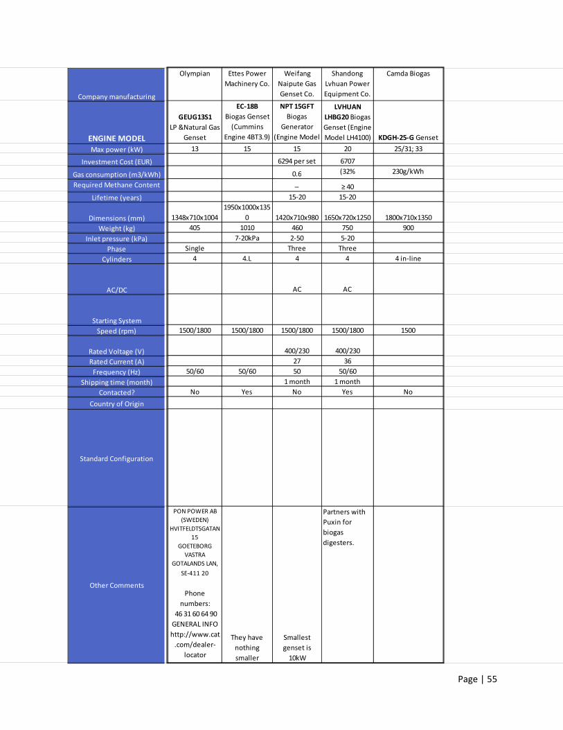
Page | 55
Company manufacturing
ENGINE MODELMax power (kW)
Investment Cost (EUR)
Gas consumption (m3/kWh)
Required Methane Content
Lifetime (years)
Dimensions (mm)
Weight (kg)
Inlet pressure (kPa)
Phase
Cylinders
AC/DC
Starting System
Speed (rpm)
Rated Voltage (V)
Rated Current (A)
Frequency (Hz)
Shipping time (month)
Contacted?
Country of Origin
Standard Configuration
Other Comments
Olympian Ettes Power
Machinery Co.
Weifang
Naipute Gas
Genset Co.
Shandong
Lvhuan Power
Equipment Co.
Camda Biogas
GEUG13S1
LP &Natural Gas
Genset
EC‐18B
Biogas Genset
(Cummins
Engine 4BT3.9)
NPT 15GFT
Biogas
Generator
(Engine Model
LVHUAN
LHBG20 Biogas
Genset (Engine
Model LH4100) KDGH‐25‐G Genset
13 15 15 20 25/31; 33
6294 per set 6707
0.6 (32% 230g/kWh
─ ≥ 40
15‐20 15‐20
1348x710x1004
1950x1000x135
0 1420x710x980 1650x720x1250 1800x710x1350
405 1010 460 750 900
7‐20kPa 2‐50 5‐20
Single Three Three
4 4.L 4 4 4 in‐line
AC AC
1500/1800 1500/1800 1500/1800 1500/1800 1500
400/230 400/230
27 36
50/60 50/60 50 50/60
1 month 1 month
No Yes No Yes No
PON POWER AB
(SWEDEN)
HVITFELDTSGATAN
15
GOETEBORG
VASTRA
GOTALANDS LAN,
SE‐411 20
Phone
numbers:
46 31 60 64 90
GENERAL INFO
http://www.cat
.com/dealer‐
locator
They have
nothing
smaller
Smallest
genset is
10kW
Partners with
Puxin for
biogas
digesters.

Page | 56
AppendixE–QuotesandOfficialInformationfromSuppliers
E.1 BiogasAustraliaGensetSpecifications

Page | 57
E.2 BiogasAustraliaDigesterSpecifications

Page | 58
E.3 WuhanACME1kWGensetQuoteandSpecifications

Page | 59
E.4 WuhanACMEHouseholdBiodigesterQuotation

Page | 60
E.5 ChengduRaretech2kWGensetSpecifications

Page | 61

Page | 62
AppendixF–MatlabCode
% By: Niara Wright
% Biogas Yield Calculations
% Domain: KTH Polygeneration Research team
% Variable Definition
% DigV = Minimum digester volume required
% GasVS = volume of biogas yield per kg of VS
% GasPerCow = Volume of biogas yielded per day per cow
% GasProd = Volume of biogas produced per day
% GasReq = Volume of biogas required per day to run the engine
% HRT = Hydraulic Retention Time (days)
% H2OV = Volume of Dilution water needed to reach the optimal solids
% content
% Manure = Mass of manure produced by one cow
% ManureV = Volume of manure produced by one cow
% ManureReq = Mass of manure required to sustain electricity capacity
% OLR = Organic Loading Rate
% OSC = Optimal Solids Content of manure is 6‐8% according to the
% literature.
% OVSC = Optimal Volatile Solids Content of manure
% SlurryV = total volume of slurry after dilution
% TSC = total solids content of manure
% TSCow = total solids content of manure/cow/day
% VSD = Mass of volatile solids destroyed in digester
% VSManure = Volume of VS produced by one cow
% VSDig = Mass of VS inside of the digester
% VSDPerc = % volatile solids degraded in digester
% VSPerc = % volatile solids in manure (%)
% VSReq = Mass of VS required for engine
conv = 0.1; % m3 of digester volume per kg of slurry (estimated from POY)
GasVSD = 0.6861; % m3 biogas/kg VS INPUT VALUE: Based on type of cow
GasCow = 0.96; % m3 biogas/cow/day (from MinOfAgro)
% HRT = 25; % days INPUT VALUE: Digester spec
OLR = 4; % kg VS/m3 digester INPUT VALUE: Digester spec

Page | 63
OSC = 0.08;
TSC = 0.4;
VSDPerc = 40;
VSTS = 0.76; % VS/TS (TS is 76% VS)
LiveWeight = 500; % kg
%% Original: Based on biogas yield per cow specification
% ENGINE
MaxPwr = 1.2; % kW INPUT VALUE: Biogas Australia 1.2 kW Genset
GasConsR = 0.7; % m3/kWh INPUT VALUE
Target = 3.6; % kWh
Hours = Target/MaxPwr; % Hours required to reach target capacity
GasReq = GasConsR*Target; % Volume of biogas required per day (m3)
% DIGESTION
CowsReq = GasReq/GasCow;
TSCow = 0.008*LiveWeight; % kg
TSReq = TSCow*CowsReq; % kg
ManureReq = TSReq*(1/TSC); % kg
H2OReq = (ManureReq*TSC)/OSC‐ManureReq; % kg
SlurryReq = ManureReq + H2OReq % kg
DigV = SlurryReq*conv; % m3
fprintf('%0 .2f m3 of biogas are required to run the engine,\n thus you need a % d m3 digester
and % d cows to supply % d kg of manure each day. \n',...
GasReq,ceil(DigV),ceil(CowsReq),ceil(ManureReq))
%% Alternate: Uses biogas yield per kg of VS added specification.
%This calculation takes into account the amount of volatile solids that are actually degraded
in the digester.
% ENGINE
MaxPwr = 1.2; % kW INPUT VALUE: Biogas Australia 1.2 kW Genset
GasConsR = 0.7; % m3/kWh INPUT VALUE

Page | 64
Target = 3.6; % kWh
Hours = Target/MaxPwr; % Hours required to reach target capacity
GasReq = GasConsR*Target; % Volume of biogas required per day (m3)
% DIGESTION
TSCow = 0.008*LiveWeight; % kg TS/cow
ManureCow = TSCow*(1/TSC); % kg manure/cow
% GasCowCalc = TSCow*VSTS*GasVS
GasCowCalc = TSCow*VSTS*(VSDPerc/100)*GasVSD % This would be used if the biogas yield
is given per unit of VS destroyed not just VS added
CowsReqAlt = GasReq/GasCowCalc
TSReqAlt = TSCow*CowsReqAlt; % kg
ManureReqAlt = TSReqAlt*(1/TSC); % kg
H2OReqAlt = (ManureReqAlt*TSC)/OSC‐ManureReqAlt; % kg
SlurryReqAlt = ManureReqAlt + H2OReqAlt % kg
DigVAlt = SlurryReqAlt*conv; % m3
% DigVAlt = (TSReqAlt*VSTS)/OLR; % m3
fprintf('Alternate: %0 .2f m3 of biogas are required to run the engine,\n thus you need a % d
m3 digester and % d cows to supply % d kg of manure each day. \n',...
GasReq,ceil(DigVAlt),ceil(CowsReqAlt),ceil(ManureReqAlt))


