Biologically-Inspired Locomotion of a 2g Hexapod Robot · PDF fileBiologically-Inspired...
6
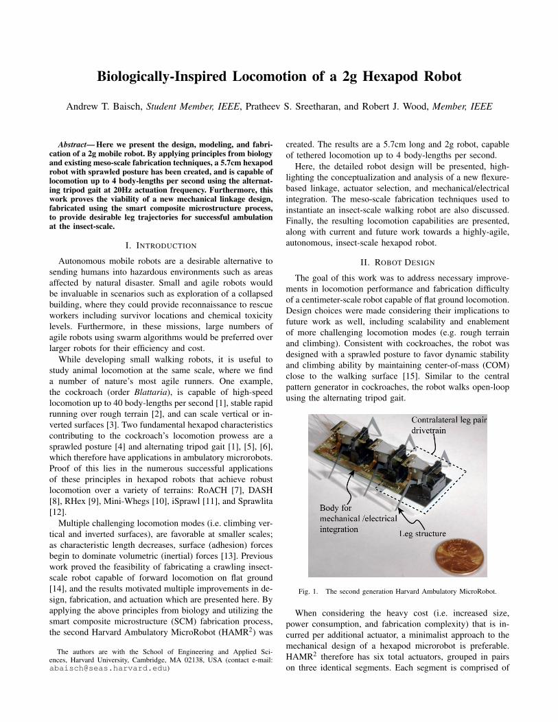
Biologically-Inspired Locomotion of a 2g Hexapod Robot Andrew T. Baisch, Student Member, IEEE, Pratheev S. Sreetharan, and Robert J. Wood, Member, IEEE Abstract— Here we present the design, modeling, and fabri- cation of a 2g mobile robot. By applying principles from biology and existing meso-scale fabrication techniques, a 5.7cm hexapod robot with sprawled posture has been created, and is capable of locomotion up to 4 body-lengths per second using the alternat- ing tripod gait at 20Hz actuation frequency. Furthermore, this work proves the viability of a new mechanical linkage design, fabricated using the smart composite microstructure process, to provide desirable leg trajectories for successful ambulation at the insect-scale. I. I NTRODUCTION Autonomous mobile robots are a desirable alternative to sending humans into hazardous environments such as areas affected by natural disaster. Small and agile robots would be invaluable in scenarios such as exploration of a collapsed building, where they could provide reconnaissance to rescue workers including survivor locations and chemical toxicity levels. Furthermore, in these missions, large numbers of agile robots using swarm algorithms would be preferred over larger robots for their efficiency and cost. While developing small walking robots, it is useful to study animal locomotion at the same scale, where we find a number of nature’s most agile runners. One example, the cockroach (order Blattaria), is capable of high-speed locomotion up to 40 body-lengths per second [1], stable rapid running over rough terrain [2], and can scale vertical or in- verted surfaces [3]. Two fundamental hexapod characteristics contributing to the cockroach’s locomotion prowess are a sprawled posture [4] and alternating tripod gait [1], [5], [6], which therefore have applications in ambulatory microrobots. Proof of this lies in the numerous successful applications of these principles in hexapod robots that achieve robust locomotion over a variety of terrains: RoACH [7], DASH [8], RHex [9], Mini-Whegs [10], iSprawl [11], and Sprawlita [12]. Multiple challenging locomotion modes (i.e. climbing ver- tical and inverted surfaces), are favorable at smaller scales; as characteristic length decreases, surface (adhesion) forces begin to dominate volumetric (inertial) forces [13]. Previous work proved the feasibility of fabricating a crawling insect- scale robot capable of forward locomotion on flat ground [14], and the results motivated multiple improvements in de- sign, fabrication, and actuation which are presented here. By applying the above principles from biology and utilizing the smart composite microstructure (SCM) fabrication process, the second Harvard Ambulatory MicroRobot (HAMR 2 ) was The authors are with the School of Engineering and Applied Sci- ences, Harvard University, Cambridge, MA 02138, USA (contact e-mail: [email protected]) created. The results are a 5.7cm long and 2g robot, capable of tethered locomotion up to 4 body-lengths per second. Here, the detailed robot design will be presented, high- lighting the conceptualization and analysis of a new flexure- based linkage, actuator selection, and mechanical/electrical integration. The meso-scale fabrication techniques used to instantiate an insect-scale walking robot are also discussed. Finally, the resulting locomotion capabilities are presented, along with current and future work towards a highly-agile, autonomous, insect-scale hexapod robot. II. ROBOT DESIGN The goal of this work was to address necessary improve- ments in locomotion performance and fabrication difficulty of a centimeter-scale robot capable of flat ground locomotion. Design choices were made considering their implications to future work as well, including scalability and enablement of more challenging locomotion modes (e.g. rough terrain and climbing). Consistent with cockroaches, the robot was designed with a sprawled posture to favor dynamic stability and climbing ability by maintaining center-of-mass (COM) close to the walking surface [15]. Similar to the central pattern generator in cockroaches, the robot walks open-loop using the alternating tripod gait. Fig. 1. The second generation Harvard Ambulatory MicroRobot. When considering the heavy cost (i.e. increased size, power consumption, and fabrication complexity) that is in- curred per additional actuator, a minimalist approach to the mechanical design of a hexapod microrobot is preferable. HAMR 2 therefore has six total actuators, grouped in pairs on three identical segments. Each segment is comprised of
Transcript of Biologically-Inspired Locomotion of a 2g Hexapod Robot · PDF fileBiologically-Inspired...
Biologically-Inspired Locomotion of a 2g Hexapod Robot
Andrew T. Baisch, Student Member, IEEE, Pratheev S. Sreetharan, and Robert J. Wood, Member, IEEE
Abstract— Here we present the design, modeling, and fabri-cation of a 2g mobile robot. By applying principles from biologyand existing meso-scale fabrication techniques, a 5.7cm hexapodrobot with sprawled posture has been created, and is capable oflocomotion up to 4 body-lengths per second using the alternat-ing tripod gait at 20Hz actuation frequency. Furthermore, thiswork proves the viability of a new mechanical linkage design,fabricated using the smart composite microstructure process,to provide desirable leg trajectories for successful ambulationat the insect-scale.
I. INTRODUCTION
Autonomous mobile robots are a desirable alternative tosending humans into hazardous environments such as areasaffected by natural disaster. Small and agile robots wouldbe invaluable in scenarios such as exploration of a collapsedbuilding, where they could provide reconnaissance to rescueworkers including survivor locations and chemical toxicitylevels. Furthermore, in these missions, large numbers ofagile robots using swarm algorithms would be preferred overlarger robots for their efficiency and cost.
While developing small walking robots, it is useful tostudy animal locomotion at the same scale, where we finda number of nature’s most agile runners. One example,the cockroach (order Blattaria), is capable of high-speedlocomotion up to 40 body-lengths per second [1], stable rapidrunning over rough terrain [2], and can scale vertical or in-verted surfaces [3]. Two fundamental hexapod characteristicscontributing to the cockroach’s locomotion prowess are asprawled posture [4] and alternating tripod gait [1], [5], [6],which therefore have applications in ambulatory microrobots.Proof of this lies in the numerous successful applicationsof these principles in hexapod robots that achieve robustlocomotion over a variety of terrains: RoACH [7], DASH[8], RHex [9], Mini-Whegs [10], iSprawl [11], and Sprawlita[12].
Multiple challenging locomotion modes (i.e. climbing ver-tical and inverted surfaces), are favorable at smaller scales;as characteristic length decreases, surface (adhesion) forcesbegin to dominate volumetric (inertial) forces [13]. Previouswork proved the feasibility of fabricating a crawling insect-scale robot capable of forward locomotion on flat ground[14], and the results motivated multiple improvements in de-sign, fabrication, and actuation which are presented here. Byapplying the above principles from biology and utilizing thesmart composite microstructure (SCM) fabrication process,the second Harvard Ambulatory MicroRobot (HAMR2) was
The authors are with the School of Engineering and Applied Sci-ences, Harvard University, Cambridge, MA 02138, USA (contact e-mail:[email protected])
created. The results are a 5.7cm long and 2g robot, capableof tethered locomotion up to 4 body-lengths per second.
Here, the detailed robot design will be presented, high-lighting the conceptualization and analysis of a new flexure-based linkage, actuator selection, and mechanical/electricalintegration. The meso-scale fabrication techniques used toinstantiate an insect-scale walking robot are also discussed.Finally, the resulting locomotion capabilities are presented,along with current and future work towards a highly-agile,autonomous, insect-scale hexapod robot.
II. ROBOT DESIGN
The goal of this work was to address necessary improve-ments in locomotion performance and fabrication difficultyof a centimeter-scale robot capable of flat ground locomotion.Design choices were made considering their implications tofuture work as well, including scalability and enablementof more challenging locomotion modes (e.g. rough terrainand climbing). Consistent with cockroaches, the robot wasdesigned with a sprawled posture to favor dynamic stabilityand climbing ability by maintaining center-of-mass (COM)close to the walking surface [15]. Similar to the centralpattern generator in cockroaches, the robot walks open-loopusing the alternating tripod gait.
Fig. 1. The second generation Harvard Ambulatory MicroRobot.
When considering the heavy cost (i.e. increased size,power consumption, and fabrication complexity) that is in-curred per additional actuator, a minimalist approach to themechanical design of a hexapod microrobot is preferable.HAMR2 therefore has six total actuators, grouped in pairson three identical segments. Each segment is comprised of
all components necessary to drive two contralateral legs,and are modular to decrease fabrication difficulty, as will bediscussed in Section III. The mechanics and electronics ofthe three segments are integrated by a single body, detailedin Section II-C.
A. Mechanical Design
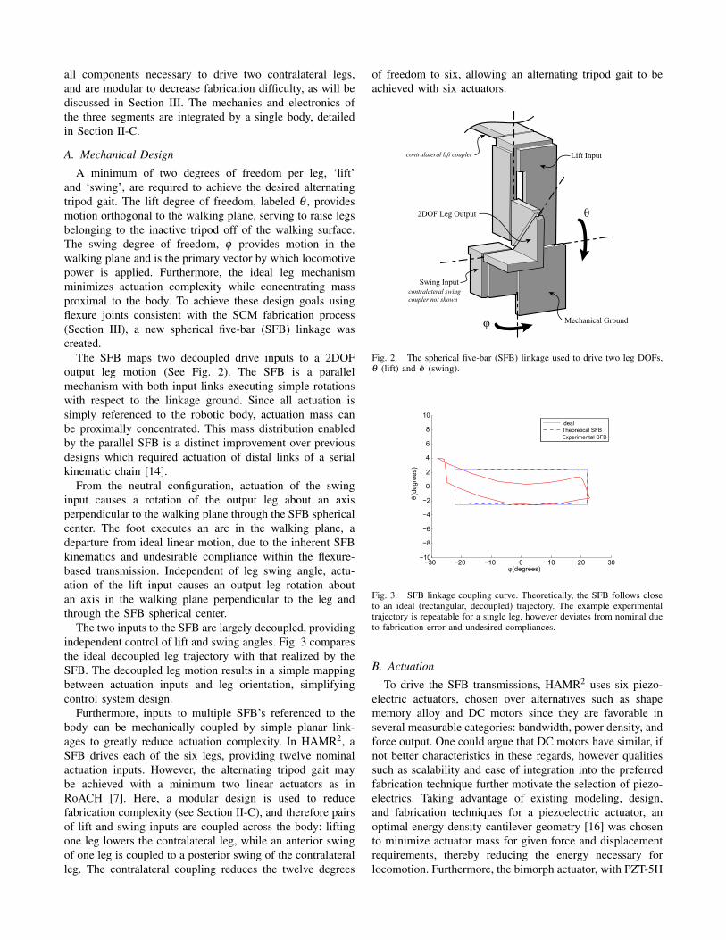
A minimum of two degrees of freedom per leg, ‘lift’and ‘swing’, are required to achieve the desired alternatingtripod gait. The lift degree of freedom, labeled θ , providesmotion orthogonal to the walking plane, serving to raise legsbelonging to the inactive tripod off of the walking surface.The swing degree of freedom, φ provides motion in thewalking plane and is the primary vector by which locomotivepower is applied. Furthermore, the ideal leg mechanismminimizes actuation complexity while concentrating massproximal to the body. To achieve these design goals usingflexure joints consistent with the SCM fabrication process(Section III), a new spherical five-bar (SFB) linkage wascreated.
The SFB maps two decoupled drive inputs to a 2DOFoutput leg motion (See Fig. 2). The SFB is a parallelmechanism with both input links executing simple rotationswith respect to the linkage ground. Since all actuation issimply referenced to the robotic body, actuation mass canbe proximally concentrated. This mass distribution enabledby the parallel SFB is a distinct improvement over previousdesigns which required actuation of distal links of a serialkinematic chain [14].
From the neutral configuration, actuation of the swinginput causes a rotation of the output leg about an axisperpendicular to the walking plane through the SFB sphericalcenter. The foot executes an arc in the walking plane, adeparture from ideal linear motion, due to the inherent SFBkinematics and undesirable compliance within the flexure-based transmission. Independent of leg swing angle, actu-ation of the lift input causes an output leg rotation aboutan axis in the walking plane perpendicular to the leg andthrough the SFB spherical center.
The two inputs to the SFB are largely decoupled, providingindependent control of lift and swing angles. Fig. 3 comparesthe ideal decoupled leg trajectory with that realized by theSFB. The decoupled leg motion results in a simple mappingbetween actuation inputs and leg orientation, simplifyingcontrol system design.
Furthermore, inputs to multiple SFB’s referenced to thebody can be mechanically coupled by simple planar link-ages to greatly reduce actuation complexity. In HAMR2, aSFB drives each of the six legs, providing twelve nominalactuation inputs. However, the alternating tripod gait maybe achieved with a minimum two linear actuators as inRoACH [7]. Here, a modular design is used to reducefabrication complexity (see Section II-C), and therefore pairsof lift and swing inputs are coupled across the body: liftingone leg lowers the contralateral leg, while an anterior swingof one leg is coupled to a posterior swing of the contralateralleg. The contralateral coupling reduces the twelve degrees
of freedom to six, allowing an alternating tripod gait to beachieved with six actuators.
Lift Input
Swing Input
Mechanical Ground
θ
φ
contralateral swingcoupler not shown
contralateral lift coupler
2DOF Leg Output
Fig. 2. The spherical five-bar (SFB) linkage used to drive two leg DOFs,θ (lift) and φ (swing).
−30 −20 −10 0 10 20 30−10
−8
−6
−4
−2
0
2
4
6
8
10
φ (degrees)
θ (d
egre
es)
IdealTheoretical SFBExperimental SFB
Fig. 3. SFB linkage coupling curve. Theoretically, the SFB follows closeto an ideal (rectangular, decoupled) trajectory. The example experimentaltrajectory is repeatable for a single leg, however deviates from nominal dueto fabrication error and undesired compliances.
B. Actuation
To drive the SFB transmissions, HAMR2 uses six piezo-electric actuators, chosen over alternatives such as shapememory alloy and DC motors since they are favorable inseveral measurable categories: bandwidth, power density, andforce output. One could argue that DC motors have similar, ifnot better characteristics in these regards, however qualitiessuch as scalability and ease of integration into the preferredfabrication technique further motivate the selection of piezo-electrics. Taking advantage of existing modeling, design,and fabrication techniques for a piezoelectric actuator, anoptimal energy density cantilever geometry [16] was chosento minimize actuator mass for given force and displacementrequirements, thereby reducing the energy necessary forlocomotion. Furthermore, the bimorph actuator, with PZT-5H
piezoelectric layers (Piezo Systems Inc. www.piezo.com) anda single carbon fiber elastic layer, has been proven suitablefor microrobot applications [17], [18], and is easily integratedinto the fabrication process described in Section III.
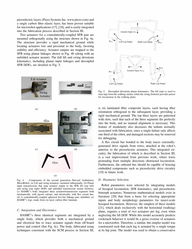
Two actuators for a contralaterally-coupled SFB pair aremounted orthogonally using the structure shown in Fig. 4a.The structure provides a rigid mechanical ground whilelocating actuators low and proximal to the body, favoringstability and efficiency. Actuator outputs are mapped to theSFB using planar linkages shown in Fig. 4b (along with anunfolded actuator mount). The full lift and swing drivetrainkinematics, including planar input linkages and decoupledSFB DOFs, are detailed in Fig. 5.
(a) (b)
(c) (d)
(e)
Fig. 4. Components of the second generation Harvard AmbulatoryMicroRobot: (a) Lift and swing actuators, mounted orthogonally. (b) Planarinput transmissions that map actuator output to the SFB lift (top left)and swing (top right) DOFs and unfolded transmission mount (bottom).(c) HAMR2’s body integrates three actuator/transmission segments bothmechanically, with jigsaw cutouts, and electrically, with flex circuit bus.(d) A contralaterally-coupled spherical five-bar linkage pair, unfolded. (e)HAMR2’s legs, made from six-layer carbon fiber laminate.
C. Integration and Electronics
HAMR2’s three identical segments are integrated by asingle body, which provides both a mechanical groundand electrical bus to trace actuator signals from off-boardpower and control (See Fig. 4c). The body, fabricated usingtechniques consistent with the SCM process in Section III,
Actuator Input, δSwing
Left Leg Output Right Leg Output
φLeft
φRight
Actuator Input, δLift
θRightθLeft Right Leg OutputLeft Leg Output
Fig. 5. Decoupled drivetrain planar kinematics. The lift (top) is used toraise legs from the walking surface while the swing (bottom) provides powerfor locomotion in the walking plane.
is six laminated fiber composite layers, each having fiberorientation orthogonal to the subsequent layer, providing arigid mechanical ground. The top three layers are patternedwith slots, such that each of the three segments fits perfectlyinto the body, and no manual alignment is necessary. Thisfeature of modularity also decreases the tedium normallyassociated with fabrication, since a single failure only affectsone third of the robot, and damaged sections may be removedfor debugging.
A flex circuit bus bonded to the body traces externally-generated drive signals from wires, attached at the robot’santerior, to the piezoelectric actuators. This integrated cir-cuitry, the fabrication of which is described in Section III,is a vast improvement from previous work, where wiresprotruding from multiple directions obstructed locomotion.Furthermore, the onboard bus should be capable of housingembedded components such as piezoelectric drive circuitry[19] in future work.
D. Parameter Selection
Robot parameters were selected by integrating modelsof hexapod locomotion, SFB kinematics, and piezoelectricbimorph actuators. Numerous mathematical models exist inliterature [20] that form a basis for selecting appropriateinputs and body morphology parameters for insect-scalehexapod locomotion. However, the simplest of these models[21], which deals exclusively with the horizontal (walking)plane, requires a total of two actuators per leg, even whenneglecting the lift DOF. While this model accurately predictscockroach behavior it would be a gross overuse of actuatorsfor a microrobot. Therefore, a similar, but simpler model wasconstructed such that each leg is actuated by a single torqueat its hip joint. The model was used to obtain a conservative
estimate of the necessary hip-torque inputs to achieve thedesired locomotion of a hexapod robot.
Decoupled horizontal and vertical plane kinematic modelsof the SFB (See Fig. 5) were created, assuming swingand lift DOFs are sufficiently decoupled. The swing planemodel quasi-statically maps hip torque approximations fromhorizontal-plane dynamics to the actuator output, ensuringactuator force and displacement outputs sufficient for loco-motion. Similarly, lift plane kinematics ensure that actuatoroutputs are sufficient to lift the robot. An existing actuatormodel [16] was used to determine geometric parameters foran energy density-optimizing piezoelectric cantilever, usingconservative estimates of necessary actuator outputs obtainedfrom the dynamic and kinematic models. The results of thisanalysis yielded HAMR2’s design parameters, summarizedin Table I.
III. FABRICATION
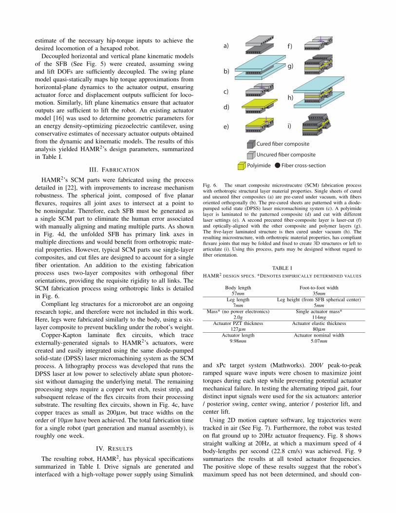
HAMR2’s SCM parts were fabricated using the processdetailed in [22], with improvements to increase mechanismrobustness. The spherical joint, composed of five planarflexures, requires all joint axes to intersect at a point tobe nonsingular. Therefore, each SFB must be generated asa single SCM part to eliminate the human error associatedwith manually aligning and mating multiple parts. As shownin Fig. 4d, the unfolded SFB has primary link axes inmultiple directions and would benefit from orthotropic mate-rial properties. However, typical SCM parts use single-layercomposites, and cut files are designed to account for a singlefiber orientation. An addition to the existing fabricationprocess uses two-layer composites with orthogonal fiberorientations, providing the requisite rigidity to all links. TheSCM fabrication process using orthotropic links is detailedin Fig. 6.
Compliant leg structures for a microrobot are an ongoingresearch topic, and therefore were not included in this work.Here, legs were fabricated similarly to the body, using a six-layer composite to prevent buckling under the robot’s weight.
Copper-Kapton laminate flex circuits, which traceexternally-generated signals to HAMR2’s actuators, werecreated and easily integrated using the same diode-pumpedsolid-state (DPSS) laser micromachining system as the SCMprocess. A lithography process was developed that runs theDPSS laser at low power to selectively ablate spun photore-sist without damaging the underlying metal. The remainingprocessing steps require a copper wet etch, resist strip, andsubsequent release of the flex circuits from their processingsubstrate. The resulting flex circuits, shown in Fig. 4c, havecopper traces as small as 200µm, but trace widths on theorder of 10µm have been achieved. The total fabrication timefor a single robot (part generation and manual assembly), isroughly one week.
IV. RESULTS
The resulting robot, HAMR2, has physical specificationssummarized in Table I. Drive signals are generated andinterfaced with a high-voltage power supply using Simulink
a)
b)
c)
d)
e)
f )
g)
h)
i)
Cured �ber composite
Uncured �ber composite
Polyimide Fiber cross-section
Fig. 6. The smart composite microstrucutre (SCM) fabrication processwith orthotropic structural layer material properties. Single sheets of curedand uncured fiber composites (a) are pre-cured under vacuum, with fibersoriented orthogonally (b). The pre-cured sheets are patterned with a diode-pumped solid state (DPSS) laser micromachining system (c). A polyimidelayer is laminated to the patterned composite (d) and cut with differentlaser settings (e). A second precured fiber-composite layer is laser-cut (f)and optically-aligned with the other composite and polymer layers (g).The five-layer laminated structure is then cured under vacuum (h). Theresulting microstructure, with orthotropic material properties, has compliantflexure joints that may be folded and fixed to create 3D structures or left toarticulate (i). Using this process, parts may be designed without regard tofiber orientation.
TABLE IHAMR2 DESIGN SPECS. *DENOTES EMPIRICALLY DETERMINED VALUES
Body length Foot-to-foot width57mm 35mm
Leg length Leg height (from SFB spherical center)7mm 5mm
Mass* (no power electronics) Single actuator mass*2.0g 114mg
Actuator PZT thickness Actuator elastic thickness127µm 80µm
Actuator length Actuator nominal width9.98mm 5.07mm
and xPc target system (Mathworks). 200V peak-to-peakramped square wave inputs were chosen to maximize jointtorques during each step while preventing potential actuatormechanical failure. In testing the alternating tripod gait, fourdistinct input signals were used for the six actuators: anterior/ posterior swing, center swing, anterior / posterior lift, andcenter lift.
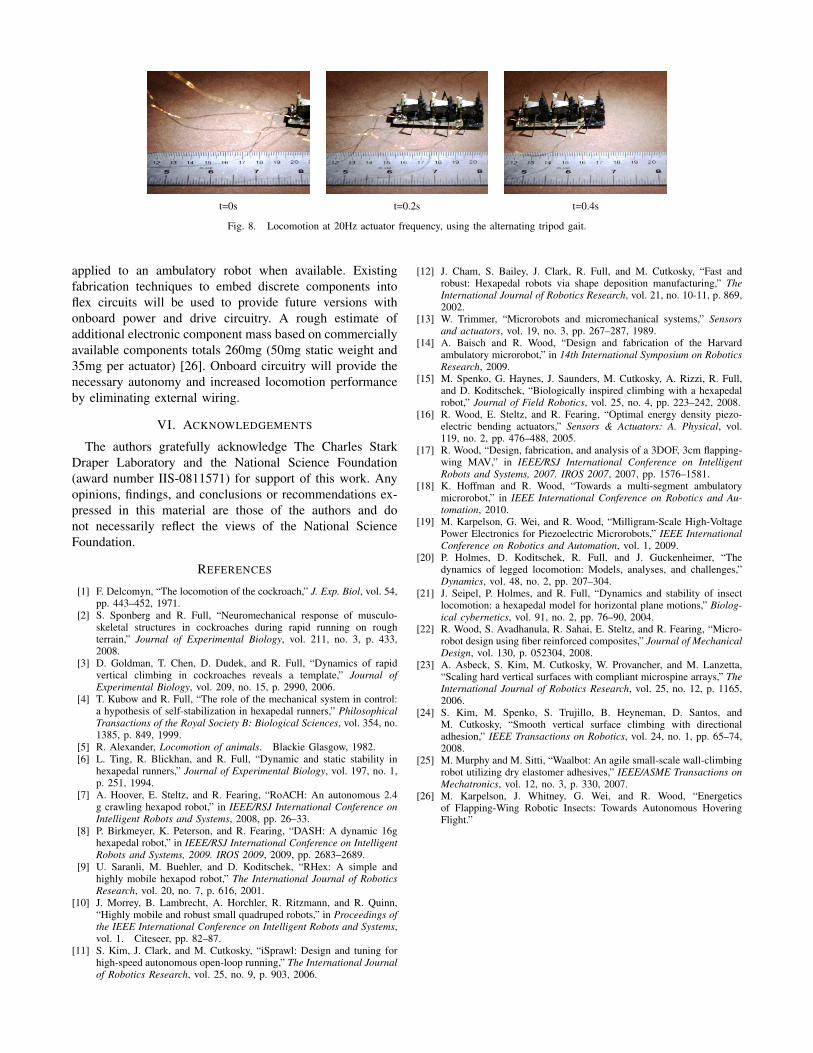
Using 2D motion capture software, leg trajectories weretracked in air (See Fig. 7). Furthermore, the robot was testedon flat ground up to 20Hz actuator frequency. Fig. 8 showsstraight walking at 20Hz, at which a maximum speed of 4body-lengths per second (22.8 cm/s) was achieved. Fig. 9summarizes the results at all tested actuator frequencies.The positive slope of these results suggest that the robot’smaximum speed has not been determined, and should con-
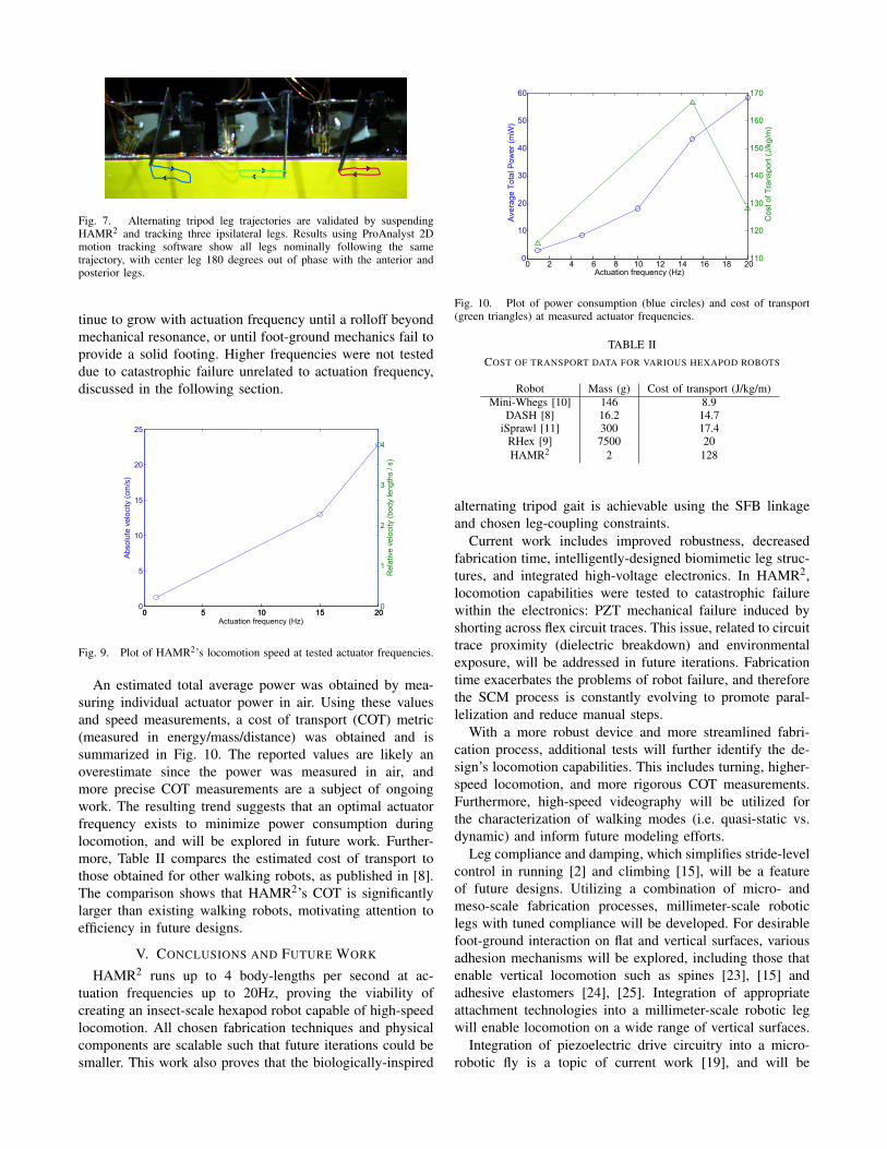
Fig. 7. Alternating tripod leg trajectories are validated by suspendingHAMR2 and tracking three ipsilateral legs. Results using ProAnalyst 2Dmotion tracking software show all legs nominally following the sametrajectory, with center leg 180 degrees out of phase with the anterior andposterior legs.
tinue to grow with actuation frequency until a rolloff beyondmechanical resonance, or until foot-ground mechanics fail toprovide a solid footing. Higher frequencies were not testeddue to catastrophic failure unrelated to actuation frequency,discussed in the following section.
0 5 10 15 200
5
10
15
20
25
Actuation frequency (Hz)
Abs
olut
e ve
loci
ty (c
m/s
)
0 5 10 15 200
1
2
3
4
Rel
ativ
e ve
loci
ty (b
ody
leng
ths
/ s)
Fig. 9. Plot of HAMR2’s locomotion speed at tested actuator frequencies.
An estimated total average power was obtained by mea-suring individual actuator power in air. Using these valuesand speed measurements, a cost of transport (COT) metric(measured in energy/mass/distance) was obtained and issummarized in Fig. 10. The reported values are likely anoverestimate since the power was measured in air, andmore precise COT measurements are a subject of ongoingwork. The resulting trend suggests that an optimal actuatorfrequency exists to minimize power consumption duringlocomotion, and will be explored in future work. Further-more, Table II compares the estimated cost of transport tothose obtained for other walking robots, as published in [8].The comparison shows that HAMR2’s COT is significantlylarger than existing walking robots, motivating attention toefficiency in future designs.
V. CONCLUSIONS AND FUTURE WORK
HAMR2 runs up to 4 body-lengths per second at ac-tuation frequencies up to 20Hz, proving the viability ofcreating an insect-scale hexapod robot capable of high-speedlocomotion. All chosen fabrication techniques and physicalcomponents are scalable such that future iterations could besmaller. This work also proves that the biologically-inspired
0 2 4 6 8 10 12 14 16 18 200
10
20
30
40
50
60
Actuation frequency (Hz)
Ave
rage
Tot
al P
ower
(mW
)
110
120
130
140
150
160
170
Cos
t of T
rans
port
(J/k
g/m
)
Fig. 10. Plot of power consumption (blue circles) and cost of transport(green triangles) at measured actuator frequencies.
TABLE IICOST OF TRANSPORT DATA FOR VARIOUS HEXAPOD ROBOTS
Robot Mass (g) Cost of transport (J/kg/m)Mini-Whegs [10] 146 8.9
DASH [8] 16.2 14.7iSprawl [11] 300 17.4
RHex [9] 7500 20HAMR2 2 128
alternating tripod gait is achievable using the SFB linkageand chosen leg-coupling constraints.
Current work includes improved robustness, decreasedfabrication time, intelligently-designed biomimetic leg struc-tures, and integrated high-voltage electronics. In HAMR2,locomotion capabilities were tested to catastrophic failurewithin the electronics: PZT mechanical failure induced byshorting across flex circuit traces. This issue, related to circuittrace proximity (dielectric breakdown) and environmentalexposure, will be addressed in future iterations. Fabricationtime exacerbates the problems of robot failure, and thereforethe SCM process is constantly evolving to promote paral-lelization and reduce manual steps.
With a more robust device and more streamlined fabri-cation process, additional tests will further identify the de-sign’s locomotion capabilities. This includes turning, higher-speed locomotion, and more rigorous COT measurements.Furthermore, high-speed videography will be utilized forthe characterization of walking modes (i.e. quasi-static vs.dynamic) and inform future modeling efforts.
Leg compliance and damping, which simplifies stride-levelcontrol in running [2] and climbing [15], will be a featureof future designs. Utilizing a combination of micro- andmeso-scale fabrication processes, millimeter-scale roboticlegs with tuned compliance will be developed. For desirablefoot-ground interaction on flat and vertical surfaces, variousadhesion mechanisms will be explored, including those thatenable vertical locomotion such as spines [23], [15] andadhesive elastomers [24], [25]. Integration of appropriateattachment technologies into a millimeter-scale robotic legwill enable locomotion on a wide range of vertical surfaces.
Integration of piezoelectric drive circuitry into a micro-robotic fly is a topic of current work [19], and will be
t=0s t=0.2s t=0.4s
Fig. 8. Locomotion at 20Hz actuator frequency, using the alternating tripod gait.
applied to an ambulatory robot when available. Existingfabrication techniques to embed discrete components intoflex circuits will be used to provide future versions withonboard power and drive circuitry. A rough estimate ofadditional electronic component mass based on commerciallyavailable components totals 260mg (50mg static weight and35mg per actuator) [26]. Onboard circuitry will provide thenecessary autonomy and increased locomotion performanceby eliminating external wiring.
VI. ACKNOWLEDGEMENTS
The authors gratefully acknowledge The Charles StarkDraper Laboratory and the National Science Foundation(award number IIS-0811571) for support of this work. Anyopinions, findings, and conclusions or recommendations ex-pressed in this material are those of the authors and donot necessarily reflect the views of the National ScienceFoundation.
REFERENCES
[1] F. Delcomyn, “The locomotion of the cockroach,” J. Exp. Biol, vol. 54,pp. 443–452, 1971.
[2] S. Sponberg and R. Full, “Neuromechanical response of musculo-skeletal structures in cockroaches during rapid running on roughterrain,” Journal of Experimental Biology, vol. 211, no. 3, p. 433,2008.
[3] D. Goldman, T. Chen, D. Dudek, and R. Full, “Dynamics of rapidvertical climbing in cockroaches reveals a template,” Journal ofExperimental Biology, vol. 209, no. 15, p. 2990, 2006.
[4] T. Kubow and R. Full, “The role of the mechanical system in control:a hypothesis of self-stabilization in hexapedal runners,” PhilosophicalTransactions of the Royal Society B: Biological Sciences, vol. 354, no.1385, p. 849, 1999.
[5] R. Alexander, Locomotion of animals. Blackie Glasgow, 1982.[6] L. Ting, R. Blickhan, and R. Full, “Dynamic and static stability in
hexapedal runners,” Journal of Experimental Biology, vol. 197, no. 1,p. 251, 1994.
[7] A. Hoover, E. Steltz, and R. Fearing, “RoACH: An autonomous 2.4g crawling hexapod robot,” in IEEE/RSJ International Conference onIntelligent Robots and Systems, 2008, pp. 26–33.
[8] P. Birkmeyer, K. Peterson, and R. Fearing, “DASH: A dynamic 16ghexapedal robot,” in IEEE/RSJ International Conference on IntelligentRobots and Systems, 2009. IROS 2009, 2009, pp. 2683–2689.
[9] U. Saranli, M. Buehler, and D. Koditschek, “RHex: A simple andhighly mobile hexapod robot,” The International Journal of RoboticsResearch, vol. 20, no. 7, p. 616, 2001.
[10] J. Morrey, B. Lambrecht, A. Horchler, R. Ritzmann, and R. Quinn,“Highly mobile and robust small quadruped robots,” in Proceedings ofthe IEEE International Conference on Intelligent Robots and Systems,vol. 1. Citeseer, pp. 82–87.
[11] S. Kim, J. Clark, and M. Cutkosky, “iSprawl: Design and tuning forhigh-speed autonomous open-loop running,” The International Journalof Robotics Research, vol. 25, no. 9, p. 903, 2006.
[12] J. Cham, S. Bailey, J. Clark, R. Full, and M. Cutkosky, “Fast androbust: Hexapedal robots via shape deposition manufacturing,” TheInternational Journal of Robotics Research, vol. 21, no. 10-11, p. 869,2002.
[13] W. Trimmer, “Microrobots and micromechanical systems,” Sensorsand actuators, vol. 19, no. 3, pp. 267–287, 1989.
[14] A. Baisch and R. Wood, “Design and fabrication of the Harvardambulatory microrobot,” in 14th International Symposium on RoboticsResearch, 2009.
[15] M. Spenko, G. Haynes, J. Saunders, M. Cutkosky, A. Rizzi, R. Full,and D. Koditschek, “Biologically inspired climbing with a hexapedalrobot,” Journal of Field Robotics, vol. 25, no. 4, pp. 223–242, 2008.
[16] R. Wood, E. Steltz, and R. Fearing, “Optimal energy density piezo-electric bending actuators,” Sensors & Actuators: A. Physical, vol.119, no. 2, pp. 476–488, 2005.
[17] R. Wood, “Design, fabrication, and analysis of a 3DOF, 3cm flapping-wing MAV,” in IEEE/RSJ International Conference on IntelligentRobots and Systems, 2007. IROS 2007, 2007, pp. 1576–1581.
[18] K. Hoffman and R. Wood, “Towards a multi-segment ambulatorymicrorobot,” in IEEE International Conference on Robotics and Au-tomation, 2010.
[19] M. Karpelson, G. Wei, and R. Wood, “Milligram-Scale High-VoltagePower Electronics for Piezoelectric Microrobots,” IEEE InternationalConference on Robotics and Automation, vol. 1, 2009.
[20] P. Holmes, D. Koditschek, R. Full, and J. Guckenheimer, “Thedynamics of legged locomotion: Models, analyses, and challenges,”Dynamics, vol. 48, no. 2, pp. 207–304.
[21] J. Seipel, P. Holmes, and R. Full, “Dynamics and stability of insectlocomotion: a hexapedal model for horizontal plane motions,” Biolog-ical cybernetics, vol. 91, no. 2, pp. 76–90, 2004.
[22] R. Wood, S. Avadhanula, R. Sahai, E. Steltz, and R. Fearing, “Micro-robot design using fiber reinforced composites,” Journal of MechanicalDesign, vol. 130, p. 052304, 2008.
[23] A. Asbeck, S. Kim, M. Cutkosky, W. Provancher, and M. Lanzetta,“Scaling hard vertical surfaces with compliant microspine arrays,” TheInternational Journal of Robotics Research, vol. 25, no. 12, p. 1165,2006.
[24] S. Kim, M. Spenko, S. Trujillo, B. Heyneman, D. Santos, andM. Cutkosky, “Smooth vertical surface climbing with directionaladhesion,” IEEE Transactions on Robotics, vol. 24, no. 1, pp. 65–74,2008.
[25] M. Murphy and M. Sitti, “Waalbot: An agile small-scale wall-climbingrobot utilizing dry elastomer adhesives,” IEEE/ASME Transactions onMechatronics, vol. 12, no. 3, p. 330, 2007.
[26] M. Karpelson, J. Whitney, G. Wei, and R. Wood, “Energeticsof Flapping-Wing Robotic Insects: Towards Autonomous HoveringFlight.”


![Complex-order dynamics in hexapod locomotion · -leg locomotion systems and several [1,18,19]. Based on this tool, the present foot–ground interaction during the robot locomotion,](https://static.fdocuments.net/doc/165x107/5f7ccd3368d50b680f1479c4/complex-order-dynamics-in-hexapod-locomotion-leg-locomotion-systems-and-several.jpg)