Biologically Inspired Locomotion Control of a …cdn.intechweb.org/pdfs/15776.pdf · 2.1 Overview...
21
20 Biologically Inspired Locomotion Control of a Climbing Robot Reinaldo de Bernardi 1 , Arturo Forner-Cordero 2 and José Jaime Da Cruz 1 1 Department of Telecommunications and Control, São Paulo University 2 Department of Mechatronics, São Paulo University Brazil 1. Introduction Gait generation is the formulation and selection of a sequence of coordinated leg and body motions that propel a legged robot along a desired path. Free gaits are the ones in which any leg is permitted to move at any time and fixed, or regular, gaits are those ones in which a specific pattern of leg movement is imposed. All animals move with fixed gaits (Pal & Jayarajan, 1991; Wettergreen & Thorpe, 1992; Pack & Kang, 1999). Online gait generation for robots with multiple degrees of freedom (DOF) is still a difficult problem, in particular for non-steady state locomotion, that is, when the robot has to move in non-structured environments with continuous variations of the speed, direction, and type of locomotor behavior (Crespi et al., 2008; Diedam et al., 2008). However, in nature, the motion of the legs follows stereotyped patterns with small variations from cycle to cycle related to the adaptation or entrainment with the environment (Taga, 1994; Forner-Cordero et al, 2006). This work addresses the problem of controlling a four legged climbing robot using a control architecture based on several coupled Central Pattern Generators (CPG). CPGs are neural circuits found in both invertebrate and vertebrate animals that can produce rhythmic patterns of neural activity even in the absence of excitatory inputs (Delcomyn, 1980; Ijspeert, 2008). The term central indicates that sensory feedback from the peripheral nervous system is not necessary to generate the rhythmical patterns, nevertheless, sensory feedback is important for the modulation of these patterns and entrain with the environment (Brown, 1914; Grillner, 1985; Collins & Stewart, 1993; Duysens & Van de Crommert, 1998). CPGs are fundamental building blocks for the motion neural circuits which present several interesting properties including distributed control, the ability to deal with redundancies, fast control loops and disturbance rejection. They also allow modulation of locomotion by simple control signals (Fukuoka, Kimura, & Cohen, 2003; Ijspeert, 2008). The purpose of CPG models is to exhibit limit cycle behavior, i.e. to produce stable rhythmic patterns. When this is the case, the system rapidly returns to its normal rhythmic behavior after transient perturbations of the state variables, thus providing robustness against perturbations. The choice of CPG is justified by the cited robustness in the generation of patterns. In addition, the artificial CPG, like its biological counterpart, can produce coordinated patterns of rhythmic activity while being modulated by control parameters (Matsuoka, 1987). www.intechopen.com
Transcript of Biologically Inspired Locomotion Control of a …cdn.intechweb.org/pdfs/15776.pdf · 2.1 Overview...

20
Biologically Inspired Locomotion Control of a Climbing Robot
Reinaldo de Bernardi1, Arturo Forner-Cordero2 and José Jaime Da Cruz1 1Department of Telecommunications and Control, São Paulo University
2Department of Mechatronics, São Paulo University Brazil
1. Introduction
Gait generation is the formulation and selection of a sequence of coordinated leg and body motions that propel a legged robot along a desired path. Free gaits are the ones in which any leg is permitted to move at any time and fixed, or regular, gaits are those ones in which a specific pattern of leg movement is imposed. All animals move with fixed gaits (Pal & Jayarajan, 1991; Wettergreen & Thorpe, 1992; Pack & Kang, 1999). Online gait generation for robots with multiple degrees of freedom (DOF) is still a difficult problem, in particular for non-steady state locomotion, that is, when the robot has to move in non-structured environments with continuous variations of the speed, direction, and type of locomotor behavior (Crespi et al., 2008; Diedam et al., 2008). However, in nature, the motion of the legs follows stereotyped patterns with small variations from cycle to cycle related to the adaptation or entrainment with the environment (Taga, 1994; Forner-Cordero et al, 2006). This work addresses the problem of controlling a four legged climbing robot using a control architecture based on several coupled Central Pattern Generators (CPG). CPGs are neural circuits found in both invertebrate and vertebrate animals that can produce rhythmic patterns of neural activity even in the absence of excitatory inputs (Delcomyn, 1980; Ijspeert, 2008). The term central indicates that sensory feedback from the peripheral nervous system is not necessary to generate the rhythmical patterns, nevertheless, sensory feedback is important for the modulation of these patterns and entrain with the environment (Brown, 1914; Grillner, 1985; Collins & Stewart, 1993; Duysens & Van de Crommert, 1998). CPGs are fundamental building blocks for the motion neural circuits which present several interesting properties including distributed control, the ability to deal with redundancies, fast control loops and disturbance rejection. They also allow modulation of locomotion by simple control signals (Fukuoka, Kimura, & Cohen, 2003; Ijspeert, 2008). The purpose of CPG models is to exhibit limit cycle behavior, i.e. to produce stable rhythmic patterns. When this is the case, the system rapidly returns to its normal rhythmic behavior after transient perturbations of the state variables, thus providing robustness against perturbations. The choice of CPG is justified by the cited robustness in the generation of patterns. In addition, the artificial CPG, like its biological counterpart, can produce coordinated patterns of rhythmic activity while being modulated by control parameters (Matsuoka, 1987).
www.intechopen.com

Biomimetic Based Applications
554
These properties, when transferred to mathematical models, make CPGs interesting building blocks for locomotion controllers in robots and have been well studied by a number of researchers with possible applications to the control of walking machines (Inagaki, Yuasa & Arai, 2003; Ishii, Masakado, & Ishii, 2004; Inagaki, Yuasa & Suzuki, 2006; Liu et al, 2007; Ijspeert, Crespi & Ryczko, 2007; Aoi & Tsuchiya, 2007; Morimoto, Endo & Nakanishi, 2008).
2. The four legged robot platform: Kamanbaré
2.1 Overview of the platform
Purporting the main goal of climbing trees for environmental research applications, a bio-inspired robotic platform named Kamanbaré was designed and built (Bernardi & Da Cruz, 2007). The project's main application is climbing trees for non-invasive research purposes, reaching points that may represent a risk to humans. The mechanical structure of the Kamanbaré platform consists of a central rigid body with four identical legs distributed symmetrically, Fig 1. Each leg comprises three links connected by three rotating joints and fixed to the central body. Each joint has 1 DOF. Identical motor and reduction groups are responsible by the rotary movements. Fig. 2 shows the kinematic configuration of a leg.
Fig. 1. Kamanbaré robot. Left: CAD model. Right: prototype picture.
2.2 Hardware architecture
The computations of locomotion strategies, motion control algorithms, sensor information processing and communication with the base station must be done in real-time. This significant computer load requires an advanced architecture processor running a very efficient operating system, therefore the ARM9 core running a Real Time Linux were chosen.
www.intechopen.com
Biologically Inspired Locomotion Control of a Climbing Robot
555
Fig. 2. Kinematic configuration of a leg.
Due to the control complexity present in this particular robotic platform, a main board for the execution of the highest hierarchical level control activities was considered. As a solution for the main board, the TS-7250 (Technologic Systems, USA) was selected. The main reasons for this choice were: it is compact, it contains different standard interfaces, and it is based on the EP9302 Cirrus Logic processor, with an ARM9 core, Fig. 3. The EP9302 implements an advanced processor core: 200 MHz ARM920T with support for a memory management unit (MMU). This ensemble allows the use of a high-level operating system, in this case Linux. The ARM920T core has a 32-bit architecture with a 5-stage pipeline, offering high performance and low energy consumption levels. With a 200 MHz clock, the TS-7250 module offers a performance approximately twice as fast as similar boards based on 586-core processors.
Fig. 3. Main board diagram.
Other motor control boards were also developed using a Texas Instruments microcontroller of the MSP430 family and specific integrated circuits to implement the power actuation module, based on the so-called H-bridge technique. To implement the control systems for the Kamanbaré platform, an electronic architecture was defined. Initially only one joint was considered as represented in Fig. 4, where the main components are shown: a DC motor, a potentiometer and a micro switch.
www.intechopen.com
Biomimetic Based Applications
556
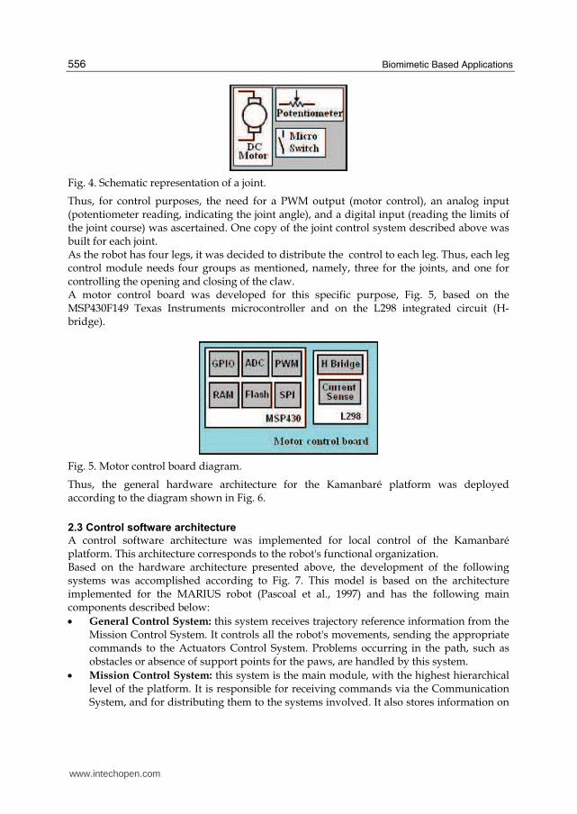
Fig. 4. Schematic representation of a joint.
Thus, for control purposes, the need for a PWM output (motor control), an analog input (potentiometer reading, indicating the joint angle), and a digital input (reading the limits of the joint course) was ascertained. One copy of the joint control system described above was built for each joint. As the robot has four legs, it was decided to distribute the control to each leg. Thus, each leg control module needs four groups as mentioned, namely, three for the joints, and one for controlling the opening and closing of the claw. A motor control board was developed for this specific purpose, Fig. 5, based on the MSP430F149 Texas Instruments microcontroller and on the L298 integrated circuit (H-bridge).
Fig. 5. Motor control board diagram.
Thus, the general hardware architecture for the Kamanbaré platform was deployed according to the diagram shown in Fig. 6.
2.3 Control software architecture
A control software architecture was implemented for local control of the Kamanbaré platform. This architecture corresponds to the robot's functional organization. Based on the hardware architecture presented above, the development of the following systems was accomplished according to Fig. 7. This model is based on the architecture implemented for the MARIUS robot (Pascoal et al., 1997) and has the following main components described below:
• General Control System: this system receives trajectory reference information from the Mission Control System. It controls all the robot's movements, sending the appropriate commands to the Actuators Control System. Problems occurring in the path, such as obstacles or absence of support points for the paws, are handled by this system.
• Mission Control System: this system is the main module, with the highest hierarchical level of the platform. It is responsible for receiving commands via the Communication System, and for distributing them to the systems involved. It also stores information on
www.intechopen.com

Biologically Inspired Locomotion Control of a Climbing Robot
557
the general status of the platform (battery voltage, position of the legs, angles of joints, etc.) keeping them available. This system gathers information from the Environmental Inspection System to be subsequently forwarded to a base station.
Fig. 6. Hardware architecture of the Kamanbaré platform.
• General Control System: this system receives trajectory reference information from the Mission Control System. It controls all the robot's movements, sending the appropriate commands to the Actuators Control System. Problems occurring in the path, such as obstacles and absence of support points for the paws, are handled by this system.
• Mission Control System: this system is the main module, with the highest hierarchical level of the platform. It is responsible for receiving commands via the Communication System, and for distributing them to the systems involved. It also stores information on the general status of the platform (battery voltage, position of the legs, angles of joints, etc.) keeping them available. This system gathers information from the Environmental Inspection System to be subsequently forwarded to a base station.
• Communication System: this system is the module in charge of the communication interfaces existing in the platform, managing communications and exchanging data with the Mission Control System.
• Environmental Inspection System: this system is responsible for gathering data from the installed sensors and for controlling any additional hardware required for that purpose as well. All acquired data are sent to the Mission Control System.
www.intechopen.com

Biomimetic Based Applications
558
Fig. 7. Kamanbaré’s control software architecture.
2.4 Kamanbaré Simulink models
The CAD model of the Kamanbaré robotic platform, described in section 2, was designed
using Solidworks® (Dassault Systèmes SolidWorks Corp). Thus a Simulink Kamanbaré
model was generated using the SolidWorks®-to-SimMechanics (MATLAB®, Simulink®, The
MathWorks Inc.) translator. This translation process is based on two major steps:
exportation of the CAD assembly into a physical modeling XML format file and importation
of the generated XML file into a SimMechanics model in Simulink®.
For the translation procedure, some configurations like the name of the joints and legs were
adopted as well the desired sense of movement, as shown in Fig. 8.
The complete model obtained for the Kamanbaré platform is depicted in Fig. 9. For a better
understanding and visualization the legs were represented as model blocks.
Since all four legs are identical, one detailed leg model block, namely, the Front Left Leg, is
described in Fig. 10.
A Gait Generator was also implemented with the main function of providing the correct
angle references for joints as functions of time. This block is presented and detailed in
section 3.
3. Gait
A gait is a repetitive (quasi-cyclical: consider small variations from cycle to cycle to adapt to
ground irregularities) pattern of foot placements (Forner-Cordero et al., 2006). It is usual to
assume that each leg is sufficiently specified as a two-state device: on the ground and off it.
The legs on the ground are supporting and propelling the robot, and those in the air are
being retracted.
www.intechopen.com

Biologically Inspired Locomotion Control of a Climbing Robot
559
Fig. 8. Kamanbaré’s configuration of joints: top view.
www.intechopen.com

Biomimetic Based Applications
560
BF
Weld1
B F
Weld
CS3 CS2
RootPart
RootGround
Conn1
Rear Right Leg
LEG 4
Conn1
Rear Left Leg
LEG 3
Env
Gait Generator
Conn1
Front Right Leg
LEG 2
Conn1
Front Left Leg
LEG 1
CS2
CS5
CS3
CS6
CS4
Corpo-1
Fig. 9. Kamanbaré’s Simulink model.
1
Conn1
simout2sJ13simout1sJ12simoutsJ11
CS3 CS2
coxa2-1
CS2 CS3
coxa1-1
CS2
canela-1
Joint
Sensor
13
Joint
Sensor
12
Joint
Sensor
11
Joint
Actuator
13
Joint
Actuator
12
Joint
Actuator
11
BF
J13
B F
J12
B F
J11
P12
From 12
P11
From 11
du/dt
Derivative4
du/dt
Derivative3
du/dt
Derivative2
du/dt
Derivative19
du/dt
Derivative18
du/dt
Derivative1
0
Constant
Fig. 10. Simulink Leg model: Front Left.
www.intechopen.com

Biologically Inspired Locomotion Control of a Climbing Robot
561
The concept of gait assumes a regular progression forwards or backwards and can be expressed as a function of time or distance. Fig. 10 presents a plan view of a walker´s footfalls at four successive times, t1, t2, t3 and t4, as it walks with a diagonal gait in which the front left (FL) and rear right (RR) legs move as a pair, and the front right (FR) and rear left (RL), as a second pair. At times t2 and t4 the walker alternates from one support pair to the other (Todd, 1985).
Fig. 11. A walker´s footfalls at four successive times. A black circle represent a foot on the ground (adapted from Todd, 1985).
Fig. 12 shows the gait as a function of time. Each bar represents the time during which a foot is on the ground. This is called a gait diagram. Another way normally used to represent a gait is shown in Fig. 13 where each wave represents the joint angles as a function of time for a set of corresponding joints, for example, all the four hips joints of a robot. Quadrupeds can adopt a number of different gaits, depending upon their speed of locomotion and the terrain. Three of the more common gaits are: Walk, Trot, and Bound (Collins & Richmond, 1994). These gaits are shown schematically in Fig. 14. In the Walk, which is a slow-speed gait, the limbs move a quarter period out of turn, in a figure-eight wave. In the Trot, which is a medium-speed gait, diagonal limbs, e.g., front right and rear left, move together and in phase, and pairs of diagonal limbs move half a period out of phase with one another. The Bound, which is a fast-speed gait, is similar to the trot, except that front and rear limbs, respectively, move together and in phase.
www.intechopen.com

Biomimetic Based Applications
562
Fig. 12. Gait diagram (adapted from Todd, 1985).
0 0.5 1 1.5 2 2.5 3 3.5 4-40
-30
-20
-10
0
10
20
30
40
t (s)
Join
t A
ng
le
LEG 1
LEG 2
LEG 3
LEG 4
Fig. 13. Gait represented in the form of joint angles as functions of time.
Fig. 14. Phase relations for three common quadruped gaits: Walk, Trot and Bound (adapted from Collins & Richmond, 1994).
www.intechopen.com

Biologically Inspired Locomotion Control of a Climbing Robot
563
In the present work, a CPG model was considered to be a locomotion control for only the particular gait mode Walk.
4. CPG controller architecture
4.1 Matsuoka nonlinear neural oscillators
The model of Matsuoka’s nonlinear neural oscillator (Matsuoka, 1985, 1987; Liu et al, 2007) consists of two first-order coupled differential equations, one representing the membrane potential of the neuron and the other one, the degree of neuron fatigue, where the output of the neuron is nonlinear logic.
01
ni
r i ij j i ij
duT u w y u bv feed
dt =+ = + − +∑ (1)
ia i i
dvT v y
dt+ = (2)
{ },n _mii i sat vy eu alu= (3)
Which equation represents: 1. Membrane potential; 2. Rate of neuron fatigue; 3. Non-linear output (saturation function). The mathematical neuron model has two state variables and a few constant parameters. The first state variable is the inner variable ui, corresponding to the membrane potential of the neuron. The second state variable is vi, representing the degree of adaptation or self-inhibition in the i-th neuron, b is the adaptation constant, and yi is the output of the i-th neuron. Subscripts i, j denote the neuron number. Tr is the time constant specifying the rise time for a step input and the frequency of the output is proportional to 1/Tr. Ta is the time constant specifying the adaptation time lag, wij denotes the inhibitory synaptic connection weight from the j-th neuron to the i-th neuron, wij ≤ 0 for i ≠ j, and wij = 0 for i = j. Σ(wij yj) represents the total input from neurons inside a neural network, u0 is the constant drive input and feedi is an input feedback sensor signal to the i-th neuron representing internal sensory information and interaction between the robot and its environment; it is mainly used in a closed-loop CPG model or else it is set to zero. Input feedi may be any number of inputs applied to the i-th neuron model, which may be either proprioceptive signals or signals from other neurons. Time constants Tr and Ta change frequency and the input u0 changes amplitude. Fig. 15 shows the general Matsuoka neuron model described by the equations presented above. Assuming that the Matsuoka oscillator consists of two neurons with four state variables (Liu et al., 2007), two variables, ui and uj, represent the inner state of each neuron and the other two state variables, vi and vj, represent the degree of adaptation for each neuron. These neurons, linked reciprocally, alternately inhibit and excite each other to produce an oscillation as output. Such activity accounts for the alternating and mutually inhibition of the flexor and extensor muscles at joints during walking. The extensor and flexor are physiologically driven based on the output of each neuron. Self-inhibition is governed by b� vi and b� vj connections and mutual inhibition by wijyj and wjiyi connections, as shown in Fig. 16.
www.intechopen.com
Biomimetic Based Applications
564
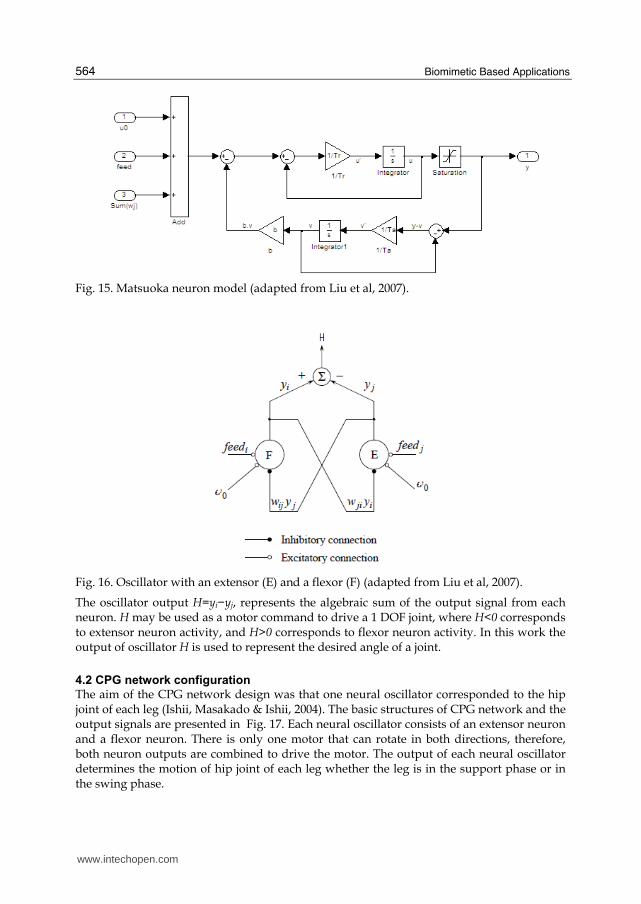
Fig. 15. Matsuoka neuron model (adapted from Liu et al, 2007).
Fig. 16. Oscillator with an extensor (E) and a flexor (F) (adapted from Liu et al, 2007).
The oscillator output H=yi−yj, represents the algebraic sum of the output signal from each neuron. H may be used as a motor command to drive a 1 DOF joint, where H<0 corresponds to extensor neuron activity, and H>0 corresponds to flexor neuron activity. In this work the output of oscillator H is used to represent the desired angle of a joint.
4.2 CPG network configuration
The aim of the CPG network design was that one neural oscillator corresponded to the hip joint of each leg (Ishii, Masakado & Ishii, 2004). The basic structures of CPG network and the output signals are presented in Fig. 17. Each neural oscillator consists of an extensor neuron and a flexor neuron. There is only one motor that can rotate in both directions, therefore, both neuron outputs are combined to drive the motor. The output of each neural oscillator determines the motion of hip joint of each leg whether the leg is in the support phase or in the swing phase.
www.intechopen.com
Biologically Inspired Locomotion Control of a Climbing Robot
565
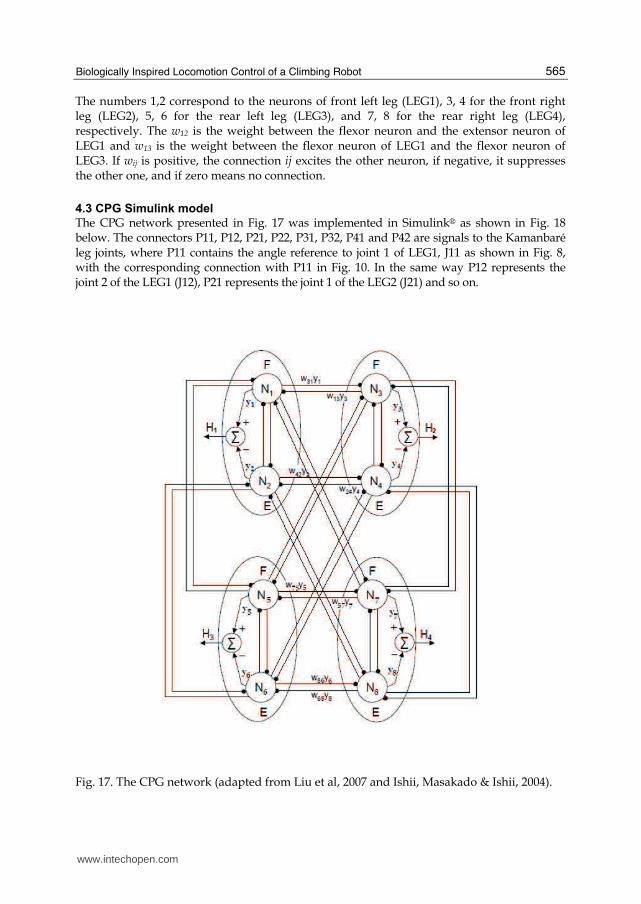
The numbers 1,2 correspond to the neurons of front left leg (LEG1), 3, 4 for the front right leg (LEG2), 5, 6 for the rear left leg (LEG3), and 7, 8 for the rear right leg (LEG4), respectively. The w12 is the weight between the flexor neuron and the extensor neuron of LEG1 and w13 is the weight between the flexor neuron of LEG1 and the flexor neuron of LEG3. If wij is positive, the connection ij excites the other neuron, if negative, it suppresses the other one, and if zero means no connection.
4.3 CPG Simulink model
The CPG network presented in Fig. 17 was implemented in Simulink® as shown in Fig. 18 below. The connectors P11, P12, P21, P22, P31, P32, P41 and P42 are signals to the Kamanbaré leg joints, where P11 contains the angle reference to joint 1 of LEG1, J11 as shown in Fig. 8, with the corresponding connection with P11 in Fig. 10. In the same way P12 represents the joint 2 of the LEG1 (J12), P21 represents the joint 1 of the LEG2 (J21) and so on.
Fig. 17. The CPG network (adapted from Liu et al, 2007 and Ishii, Masakado & Ishii, 2004).
www.intechopen.com

Biomimetic Based Applications
566
Fig. 18. The Simulink CPG network model.
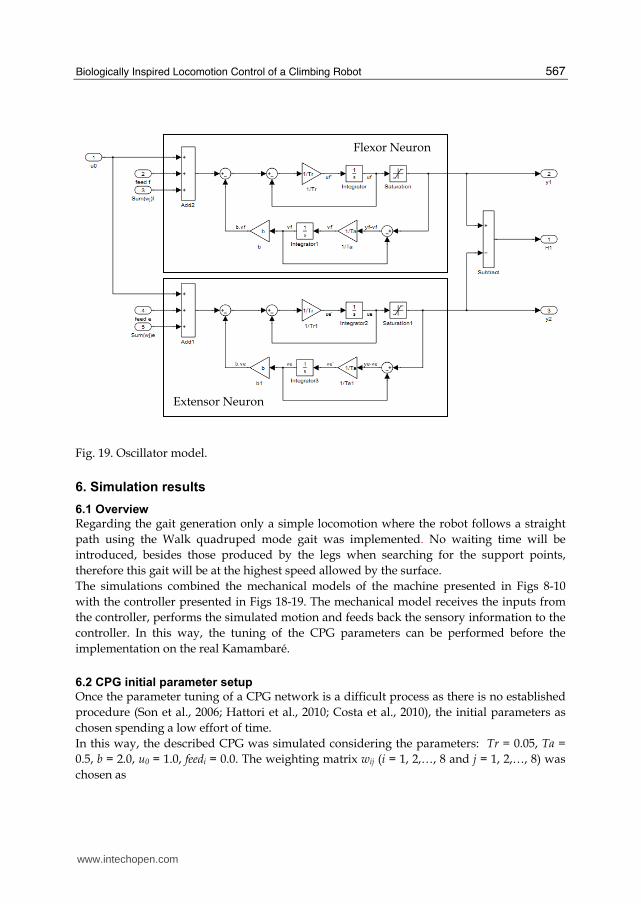
The content of Neural Oscillators blocks of Fig. 18 is the corresponding implementation of the oscillator presented in Fig. 16 with two neurons: Flexor and Extensor, as shown in Fig. 19.
www.intechopen.com
Biologically Inspired Locomotion Control of a Climbing Robot
567
Fig. 19. Oscillator model.
6. Simulation results
6.1 Overview
Regarding the gait generation only a simple locomotion where the robot follows a straight
path using the Walk quadruped mode gait was implemented. No waiting time will be
introduced, besides those produced by the legs when searching for the support points,
therefore this gait will be at the highest speed allowed by the surface.
The simulations combined the mechanical models of the machine presented in Figs 8-10
with the controller presented in Figs 18-19. The mechanical model receives the inputs from
the controller, performs the simulated motion and feeds back the sensory information to the
controller. In this way, the tuning of the CPG parameters can be performed before the
implementation on the real Kamambaré.
6.2 CPG initial parameter setup
Once the parameter tuning of a CPG network is a difficult process as there is no established
procedure (Son et al., 2006; Hattori et al., 2010; Costa et al., 2010), the initial parameters as
chosen spending a low effort of time.
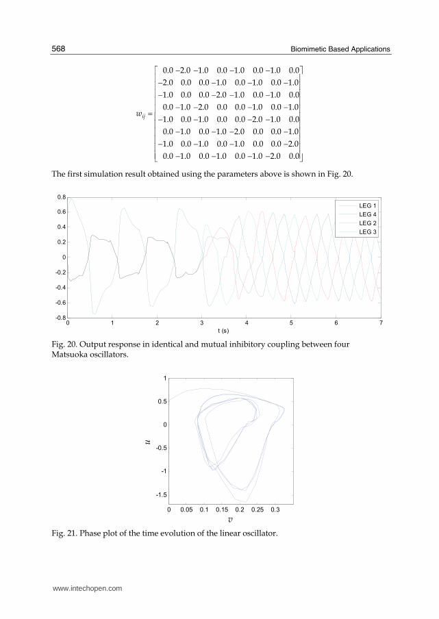
In this way, the described CPG was simulated considering the parameters: Tr = 0.05, Ta =
0.5, b = 2.0, u0 = 1.0, feedi = 0.0. The weighting matrix wij (i = 1, 2,…, 8 and j = 1, 2,…, 8) was
chosen as
Flexor Neuron
Extensor Neuron
www.intechopen.com
Biomimetic Based Applications
568
0.0 2.0 1.0 0.0 1.0
2.0 0.0 0.0 1.0 0.0
1.0 0.0 0.0 2.0
0.0 1.0 2.0 0.0
1.0 0.0 1.0 0.0
0.0 1.0 0.0 1.0
1.0 0.0 1.0 0.0
0.0 1.0 0.0 1.0
ijw
− − −− −− −
− −= − −− −
− −− −
0.0 1.0 0.0
1.0 0.0 1.0
1.0 0.0 1.0 0.0
0.0 1.0 0.0 1.0
0.0 2.0 1.0 0.0
2.0 0.0 0.0 1.0
1.0 0.0 0.0 2.0
0.0 1.0 2.0 0.0
−⎡ ⎤⎢ ⎥− −⎢ ⎥⎢ ⎥− −⎢ ⎥− −⎢ ⎥⎢ − −⎢ − −⎢⎢ − −⎢⎢ − −⎣ ⎦
⎥⎥⎥⎥⎥⎥
The first simulation result obtained using the parameters above is shown in Fig. 20.
0 1 2 3 4 5 6 7-0.8
-0.6
-0.4
-0.2
0
0.2
0.4
0.6
0.8
t (s)
LEG 1
LEG 4
LEG 2
LEG 3
Fig. 20. Output response in identical and mutual inhibitory coupling between four Matsuoka oscillators.
0 0.05 0.1 0.15 0.2 0.25 0.3
-1.5
-1
-0.5
0
0.5
1
v
u
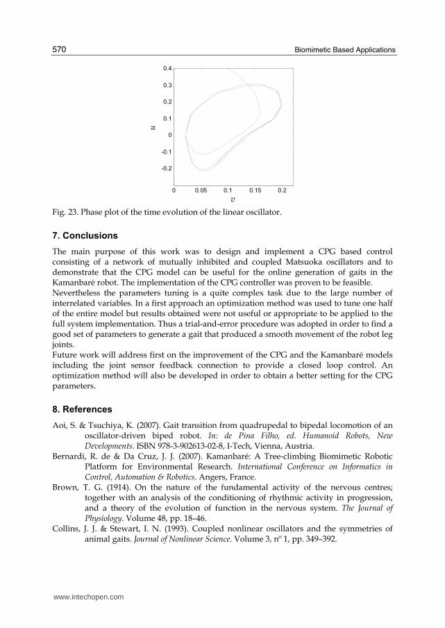
Fig. 21. Phase plot of the time evolution of the linear oscillator.
www.intechopen.com

Biologically Inspired Locomotion Control of a Climbing Robot
569
Analysing Fig. 20, certain initial transient of the oscillators can be clearly noted in the first 4 seconds of simulation. In order to better verify this behaviour, a phase plot of the state variables u and v is presented in Fig. 21. The initial transient is obviously undesirable, since it will produce a non-acceptable robot behavior, e.g movements of the legs joints. In this way, tuning of the CPG parameters turns out to be mandatory.
6.3 Parameter tuning
The parameter tuning of a CPG network is a difficult process since it implies in a task of
changing a substantial number of interrelated parameters. In this work a trial-and-error procedure was adopted in order to find a set of the parameters that provided the required control signals. Thus, after several iterations and tests for analyzing the gait wave form, it was concluded that the initial transient obtained was directly correlated to the values used as initial conditions in the integrator blocks of the neural oscillator’s models. Once these initial conditions were adjusted, the complete neural system showed a stable behaviour. The following set of parameters has then been adopted: Tr = 0.4, Ta = 0.5, b = 4.0, u0 = 1.0, feedi = 0.0 and the weighting matrix wij (i = 1, 2,…, 8 and j = 1, 2,…, 8) chosen as
0.0 1.8 1.2 0.0 1.2
1.8 0.0 0.0 1.2 0.0
1.2 0.0 0.0 1.8
0.0 1.2 1.8 0.0
1.2 0.0 1.2 0.0
0.0 1.2 0.0 1.2
1.2 0.0 1.2 0.0
0.0 1.2 0.0 1.2
ijw
− − −− −− −
− −= − −− −
− −− −
0.0 1.2 0.0
1.2 0.0 1.2
1.2 0.0 1.2 0.0
0.0 1.2 0.0 1.2
0.0 1.8 1.2 0.0
1.8 0.0 0.0 1.2
1.2 0.0 0.0 1.8
0.0 1.2 1.8 0.0
−⎡ ⎤⎢ ⎥− −⎢ ⎥⎢ ⎥− −⎢ ⎥− −⎢ ⎥⎢ − −⎢ − −⎢⎢ − −⎢⎢ − −⎣ ⎦
⎥⎥⎥⎥⎥⎥
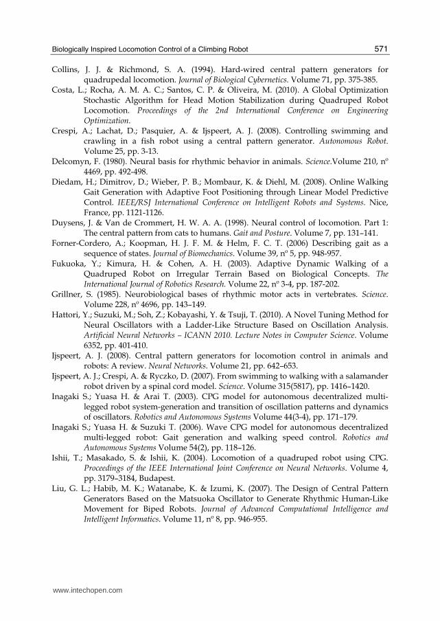
The final simulation result obtained is shown in Fig. 22, where a significant reduction of the initial transient time to about 0.8 sec can be observed. This improved behaviour can also be checked in Fig. 23 by the analysis of the phase plot of the states variables u and v.
0 1 2 3 4 5 6 7-0.4
-0.3
-0.2
-0.1
0
0.1
0.2
0.3
0.4
t (s)
LEG 1
LEG 4
LEG 2
LEG 3
Fig. 22. Output response using the tuned set of parameters.
www.intechopen.com
Biomimetic Based Applications
570
0 0.05 0.1 0.15 0.2
-0.2
-0.1
0
0.1
0.2
0.3
0.4
v
u
Fig. 23. Phase plot of the time evolution of the linear oscillator.
7. Conclusions
The main purpose of this work was to design and implement a CPG based control consisting of a network of mutually inhibited and coupled Matsuoka oscillators and to demonstrate that the CPG model can be useful for the online generation of gaits in the Kamanbaré robot. The implementation of the CPG controller was proven to be feasible. Nevertheless the parameters tuning is a quite complex task due to the large number of interrelated variables. In a first approach an optimization method was used to tune one half of the entire model but results obtained were not useful or appropriate to be applied to the full system implementation. Thus a trial-and-error procedure was adopted in order to find a good set of parameters to generate a gait that produced a smooth movement of the robot leg joints. Future work will address first on the improvement of the CPG and the Kamanbaré models including the joint sensor feedback connection to provide a closed loop control. An optimization method will also be developed in order to obtain a better setting for the CPG parameters.
8. References
Aoi, S. & Tsuchiya, K. (2007). Gait transition from quadrupedal to bipedal locomotion of an oscillator-driven biped robot. In: de Pina Filho, ed. Humanoid Robots, New Developments. ISBN 978-3-902613-02-8, I-Tech, Vienna, Austria.
Bernardi, R. de & Da Cruz, J. J. (2007). Kamanbaré: A Tree-climbing Biomimetic Robotic Platform for Environmental Research. International Conference on Informatics in Control, Automation & Robotics. Angers, France.
Brown, T. G. (1914). On the nature of the fundamental activity of the nervous centres; together with an analysis of the conditioning of rhythmic activity in progression, and a theory of the evolution of function in the nervous system. The Journal of Physiology. Volume 48, pp. 18–46.
Collins, J. J. & Stewart, I. N. (1993). Coupled nonlinear oscillators and the symmetries of animal gaits. Journal of Nonlinear Science. Volume 3, nº 1, pp. 349–392.
www.intechopen.com
Biologically Inspired Locomotion Control of a Climbing Robot
571
Collins, J. J. & Richmond, S. A. (1994). Hard-wired central pattern generators for quadrupedal locomotion. Journal of Biological Cybernetics. Volume 71, pp. 375-385.
Costa, L.; Rocha, A. M. A. C.; Santos, C. P. & Oliveira, M. (2010). A Global Optimization Stochastic Algorithm for Head Motion Stabilization during Quadruped Robot Locomotion. Proceedings of the 2nd International Conference on Engineering Optimization.
Crespi, A.; Lachat, D.; Pasquier, A. & Ijspeert, A. J. (2008). Controlling swimming and crawling in a fish robot using a central pattern generator. Autonomous Robot. Volume 25, pp. 3-13.
Delcomyn, F. (1980). Neural basis for rhythmic behavior in animals. Science.Volume 210, nº 4469, pp. 492-498.
Diedam, H.; Dimitrov, D.; Wieber, P. B.; Mombaur, K. & Diehl, M. (2008). Online Walking Gait Generation with Adaptive Foot Positioning through Linear Model Predictive Control. IEEE/RSJ International Conference on Intelligent Robots and Systems. Nice, France, pp. 1121-1126.
Duysens, J. & Van de Crommert, H. W. A. A. (1998). Neural control of locomotion. Part 1: The central pattern from cats to humans. Gait and Posture. Volume 7, pp. 131–141.
Forner-Cordero, A.; Koopman, H. J. F. M. & Helm, F. C. T. (2006) Describing gait as a sequence of states. Journal of Biomechanics. Volume 39, nº 5, pp. 948-957.
Fukuoka, Y.; Kimura, H. & Cohen, A. H. (2003). Adaptive Dynamic Walking of a Quadruped Robot on Irregular Terrain Based on Biological Concepts. The International Journal of Robotics Research. Volume 22, nº 3-4, pp. 187-202.
Grillner, S. (1985). Neurobiological bases of rhythmic motor acts in vertebrates. Science. Volume 228, nº 4696, pp. 143–149.
Hattori, Y.; Suzuki, M.; Soh, Z.; Kobayashi, Y. & Tsuji, T. (2010). A Novel Tuning Method for Neural Oscillators with a Ladder-Like Structure Based on Oscillation Analysis. Artificial Neural Networks – ICANN 2010. Lecture Notes in Computer Science. Volume 6352, pp. 401-410.
Ijspeert, A. J. (2008). Central pattern generators for locomotion control in animals and robots: A review. Neural Networks. Volume 21, pp. 642–653.
Ijspeert, A. J.; Crespi, A. & Ryczko, D. (2007). From swimming to walking with a salamander robot driven by a spinal cord model. Science. Volume 315(5817), pp. 1416–1420.
Inagaki S.; Yuasa H. & Arai T. (2003). CPG model for autonomous decentralized multi-legged robot system-generation and transition of oscillation patterns and dynamics of oscillators. Robotics and Autonomous Systems Volume 44(3-4), pp. 171–179.
Inagaki S.; Yuasa H. & Suzuki T. (2006). Wave CPG model for autonomous decentralized multi-legged robot: Gait generation and walking speed control. Robotics and Autonomous Systems Volume 54(2), pp. 118–126.
Ishii, T.; Masakado, S. & Ishii, K. (2004). Locomotion of a quadruped robot using CPG. Proceedings of the IEEE International Joint Conference on Neural Networks. Volume 4, pp. 3179–3184, Budapest.
Liu, G. L.; Habib, M. K.; Watanabe, K. & Izumi, K. (2007). The Design of Central Pattern Generators Based on the Matsuoka Oscillator to Generate Rhythmic Human-Like Movement for Biped Robots. Journal of Advanced Computational Intelligence and Intelligent Informatics. Volume 11, nº 8, pp. 946-955.
www.intechopen.com
Biomimetic Based Applications
572
Matsuoka, K. (1985). Sustained oscillations generated by mutually inhibiting neurons with adaptation. Journal of Biological Cybernetics. Volume 52, pp. 367–376.
Matsuoka, K. (1987). Mechanisms of frequency and pattern control in the neural rhythm generators. Journal of Biological Cybernetics, Volume 56, pp. 345-353.
Morimoto, J.; Endo, G. & Nakanishi, J. (2008). A biologically inspired biped locomotion strategy for humanoid robots: Modulation of sinusoidal patterns by a coupled oscillator model. IEEE Transactions on Robotics Volume 24(1), pp. 185–191.
Pack, D. J. & Kang, H. (1999), Free gait control for a quadruped walking robot. Laboratory Robotics and Automation. Volume 11, pp. 71–81.
Pal, P. K. & Jayarajan, K. (1991). Generation of Free Gait – A Graph Search Approach. IEEE Transactions on Robotics and Automation. Volume 7, nº 3, pp. 299-305.
Pascoal, A.; Oliveira, P.; Silvestre, C.; Bjerrum, A.; Ishloy, A.; Pignon, J. P.; Ayela, G. & Petzelt, C. (1997). MARIUS: An Autonomous Underwater Vehicle for Coastal Oceanography. IEEE Robotics & Automation Magazine. pp. 46-57.
Son, Y.; Kamano, T.; Yasuno, T.; Suzuki, T. & Harada, H. (2006). Generation of adaptive gait patterns for quadruped robot with CPG network including motor dynamic model. Electrical Engineering in Japan. Volume 155, Issue 1, pp. 35–43.
Taga, G. (1994). Emergence of bipedal locomotion through entrainment among the neuro- musculo-skeletal system and the environment. Physica D: Nonlinear Phenomena. Volume 75, Issue 1-3, pp. 190-208.
Todd, D. J. (1985). Walking machines: an introduction to legged robots. Published by Kogan Page Ltd.
Wettergreen, D. & Thorpe, C. (1992). Gait Generation for Legged Robots, Proceedings of the IEEE International Conference on Intelligent Robots and Systems. Volume 2, pp. 1413-1420.
www.intechopen.com

Biomimetic Based ApplicationsEdited by Prof. Marko Cavrak
ISBN 978-953-307-195-4Hard cover, 572 pagesPublisher InTechPublished online 26, April, 2011Published in print edition April, 2011
InTech EuropeUniversity Campus STeP Ri Slavka Krautzeka 83/A 51000 Rijeka, Croatia Phone: +385 (51) 770 447 Fax: +385 (51) 686 166www.intechopen.com
InTech ChinaUnit 405, Office Block, Hotel Equatorial Shanghai No.65, Yan An Road (West), Shanghai, 200040, China
Phone: +86-21-62489820 Fax: +86-21-62489821
The interaction between cells, tissues and biomaterial surfaces are the highlights of the book "BiomimeticBased Applications". In this regard the effect of nanostructures and nanotopographies and their effect on thedevelopment of a new generation of biomaterials including advanced multifunctional scaffolds for tissueengineering are discussed. The 2 volumes contain articles that cover a wide spectrum of subject matter suchas different aspects of the development of scaffolds and coatings with enhanced performance and bioactivity,including investigations of material surface-cell interactions.
How to referenceIn order to correctly reference this scholarly work, feel free to copy and paste the following:
Reinaldo de Bernardi, Arturo Forner-Cordero and José Jaime Da Cruz (2011). Biologically InspiredLocomotion Control of a Climbing Robot, Biomimetic Based Applications, Prof. Marko Cavrak (Ed.), ISBN: 978-953-307-195-4, InTech, Available from: http://www.intechopen.com/books/biomimetic-based-applications/biologically-inspired-locomotion-control-of-a-climbing-robot