BIOGAS-TECH notes
37
1 NOTES ON BIOGAS TECHNOLOGY Introduction Properties of biogas Feedstock for biogas: Aqueous wastes containing biodegradable organic matter, animal & agro - residues Microbial and biochemical aspects, Operating parameters for biogas production. Kinetics and mechanism Dry and wet fermentation. Digesters for rural application High rate digesters for industrial waste water treatment. TEXT BOOKS AND REFERENCES 1. Biotechnology Volume 8, H.J. Rehm and G. Reed, 1986, Chapter 5, „Biomethanation Processes.‟ Pp 207-267 2. K. M. Mital, Non-conventional Energy Systems, (1997), A P H Wheeler Publishing, N. Delhi. 3. K. M. Mital, Biogas Systems: Principles and Applications, (1996) New Age International Publishers (p) Ltd, N. Delhi. 4. Nijaguna, B.T., Biogas Technology, New Age International publishers (P) Ltd., 2002, Reprinted in 2009 References: 1. Effluent Treatment & Disposal: I Ch. E, U.K., Symposium Series No 96, 1986, P 137-147, Application of anaerobic biotechnology to waste treatment and energy production, Anderson & Saw. 2. „Anaerobic Rotating Biological Drum Contactor for the Treatment of Dairy Wastes‟, S. Satyanarayana, K. Thackar, S. N. Kaul, S.D. Badrinath and N.G. Swarnkar, Indian Chemical Engineer, vol 29, No 3, July-Sept, 1987
-
Upload
selfhelp-citizen-dream-merchant -
Category
Education
-
view
116 -
download
11
Transcript of BIOGAS-TECH notes
1
NOTES ON BIOGAS TECHNOLOGY
Introduction
Properties of biogas
Feedstock for biogas: Aqueous wastes containing biodegradable organic matter,
animal & agro - residues
Microbial and biochemical aspects,
Operating parameters for biogas production.
Kinetics and mechanism
Dry and wet fermentation.
Digesters for rural application
High rate digesters for industrial waste water treatment.
TEXT BOOKS AND REFERENCES
1. Biotechnology Volume 8, H.J. Rehm and G. Reed, 1986, Chapter 5,
„Biomethanation Processes.‟ Pp 207-267
2. K. M. Mital, Non-conventional Energy Systems, (1997), A P H Wheeler
Publishing, N. Delhi.
3. K. M. Mital, Biogas Systems: Principles and Applications, (1996) New Age
International Publishers (p) Ltd, N. Delhi.
4. Nijaguna, B.T., Biogas Technology, New Age International publishers (P) Ltd.,
2002, Reprinted in 2009
References:
1. Effluent Treatment & Disposal: I Ch. E, U.K., Symposium Series No 96, 1986,
P 137-147, Application of anaerobic biotechnology to waste treatment and energy
production, Anderson & Saw.
2. „Anaerobic Rotating Biological Drum Contactor for the Treatment of Dairy Wastes‟,
S. Satyanarayana, K. Thackar, S. N. Kaul, S.D. Badrinath and N.G. Swarnkar, Indian
Chemical Engineer, vol 29, No 3, July-Sept, 1987

2
3. Energy Environment Monitor, 12(1), 45-51,„Biomethanation Technologies in
Industrial Water Pollution Control‟ A. Gangagni Rao, Pune.
4. „Biogas production from sugar mill sludge by anaerobic digestion and evaluation of
bio-kinetic coefficients‟, Tharamani. P, and Elangovan. R. Indian journal of
Environmental protection, 20, (10), 745-748, 2001.
5. „Biogas Production Technology: An Indian Perspective‟, B. Nagamani and K.
Ramasamy (TNAU), Current Science, Vol7, No1, pp 44-55 10th
July, 1999
6. Khandelwal K. C. and Mahdi, “Bio-gas Technology”, Tata McGraw-Hill publ. Co.
Ltd., New Delhi, 1986.
7. State-of-the-art of anaerobic digestion technology for industrial wastewater treatment -
KV Rajeshwari, M Balakrishnan, A Kansal, K Lata, … - Renewable and Sustainable
Energy Reviews, 2000 – Elsevier
8. Anaerobic digestion technologies for energy recovery from industrial wastewater - a
study in Indian context, Arun Kansal, K V Rajeshwari, Malini Balakrishnan, Kusum
Lata, V V N Kishore, TERI Information Monitor on Environmental Science 3(2): 67–75,
9. Biogas Purification and Bottling into CNG Cylinders: Producing Bio-CNG from
Biomass for Rural Automotive Applications, Virendra K. Vijay1,*, Ram Chandra1,
Parchuri M. V. Subbarao2 and Shyam S. Kapdi3 1Centre for Rural Development and
Technology, Indian Institute of Technology, Delhi, Hauz Khas, New Delhi – 110 016,
The 2nd Joint International Conference on “Sustainable Energy and Environment (SEE
2006)” C-003 (O) 21-23 November 2006, Bangkok, Thailand
3
10. Biogas scrubbing, compression and storage: perspective and prospectus in Indian
Context, S.S. Kapdi, V.K. Vijay*, S.K. Rajesh, Rajendra Prasad, Centre for Rural
Development and Technology, Indian Institute of Technology, New Delhi 110 016
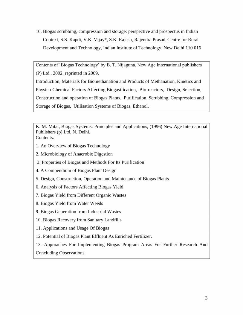
Contents of „Biogas Technology‟ by B. T. Nijaguna, New Age International publishers
(P) Ltd., 2002, reprinted in 2009.
Introduction, Materials for Biomethanation and Products of Methanation, Kinetics and
Physico-Chemical Factors Affecting Biogasification, Bio-reactors, Design, Selection,
Construction and operation of Biogas Plants, Purification, Scrubbing, Compression and
Storage of Biogas, Utilisation Systems of Biogas, Ethanol.
K. M. Mital, Biogas Systems: Principles and Applications, (1996) New Age International
Publishers (p) Ltd, N. Delhi.
Contents:
1. An Overview of Biogas Technology
2. Microbiology of Anaerobic Digestion
3. Properties of Biogas and Methods For Its Purification
4. A Compendium of Biogas Plant Design
5. Design, Construction, Operation and Maintenance of Biogas Plants
6. Analysis of Factors Affecting Biogas Yield
7. Biogas Yield from Different Organic Wastes
8. Biogas Yield from Water Weeds
9. Biogas Generation from Industrial Wastes
10. Biogas Recovery from Sanitary Landfills
11. Applications and Usage Of Biogas
12. Potential of Biogas Plant Effluent As Enriched Fertilizer.
13. Approaches For Implementing Biogas Program Areas For Further Research And
Concluding Observations
4
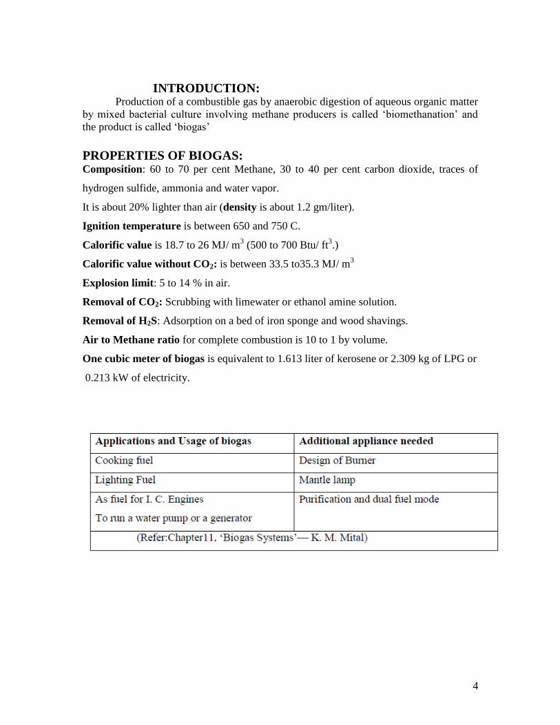
INTRODUCTION: Production of a combustible gas by anaerobic digestion of aqueous organic matter
by mixed bacterial culture involving methane producers is called „biomethanation‟ and
the product is called „biogas‟
PROPERTIES OF BIOGAS: Composition: 60 to 70 per cent Methane, 30 to 40 per cent carbon dioxide, traces of
hydrogen sulfide, ammonia and water vapor.
It is about 20% lighter than air (density is about 1.2 gm/liter).
Ignition temperature is between 650 and 750 C.
Calorific value is 18.7 to 26 MJ/ m3 (500 to 700 Btu/ ft
3.)
Calorific value without CO2: is between 33.5 to35.3 MJ/ m3
Explosion limit: 5 to 14 % in air.
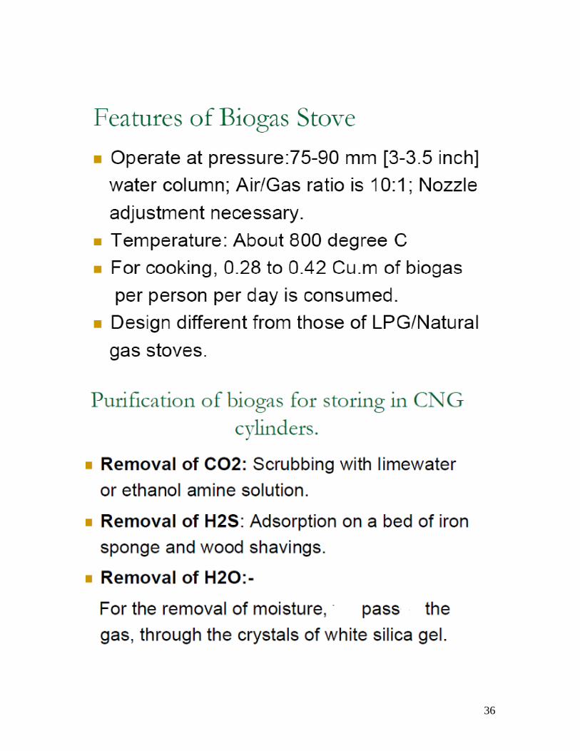
Removal of CO2: Scrubbing with limewater or ethanol amine solution.
Removal of H2S: Adsorption on a bed of iron sponge and wood shavings.
Air to Methane ratio for complete combustion is 10 to 1 by volume.
One cubic meter of biogas is equivalent to 1.613 liter of kerosene or 2.309 kg of LPG or
0.213 kW of electricity.
5
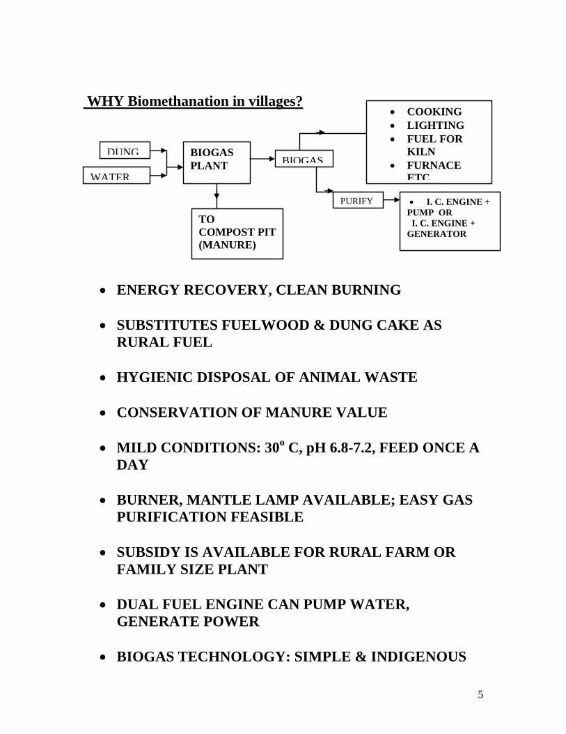
WHY Biomethanation in villages?
ENERGY RECOVERY, CLEAN BURNING
SUBSTITUTES FUELWOOD & DUNG CAKE AS
RURAL FUEL
HYGIENIC DISPOSAL OF ANIMAL WASTE
CONSERVATION OF MANURE VALUE
MILD CONDITIONS: 30o C, pH 6.8-7.2, FEED ONCE A
DAY
BURNER, MANTLE LAMP AVAILABLE; EASY GAS
PURIFICATION FEASIBLE
SUBSIDY IS AVAILABLE FOR RURAL FARM OR
FAMILY SIZE PLANT
DUAL FUEL ENGINE CAN PUMP WATER,
GENERATE POWER
BIOGAS TECHNOLOGY: SIMPLE & INDIGENOUS
DUNG
WATER
BIOGAS
PLANT BIOGAS
PURIFY I. C. ENGINE +
PUMP OR
I. C. ENGINE +
GENERATOR
COOKING
LIGHTING
FUEL FOR
KILN
FURNACE
ETC.
TO
COMPOST PIT
(MANURE)
6
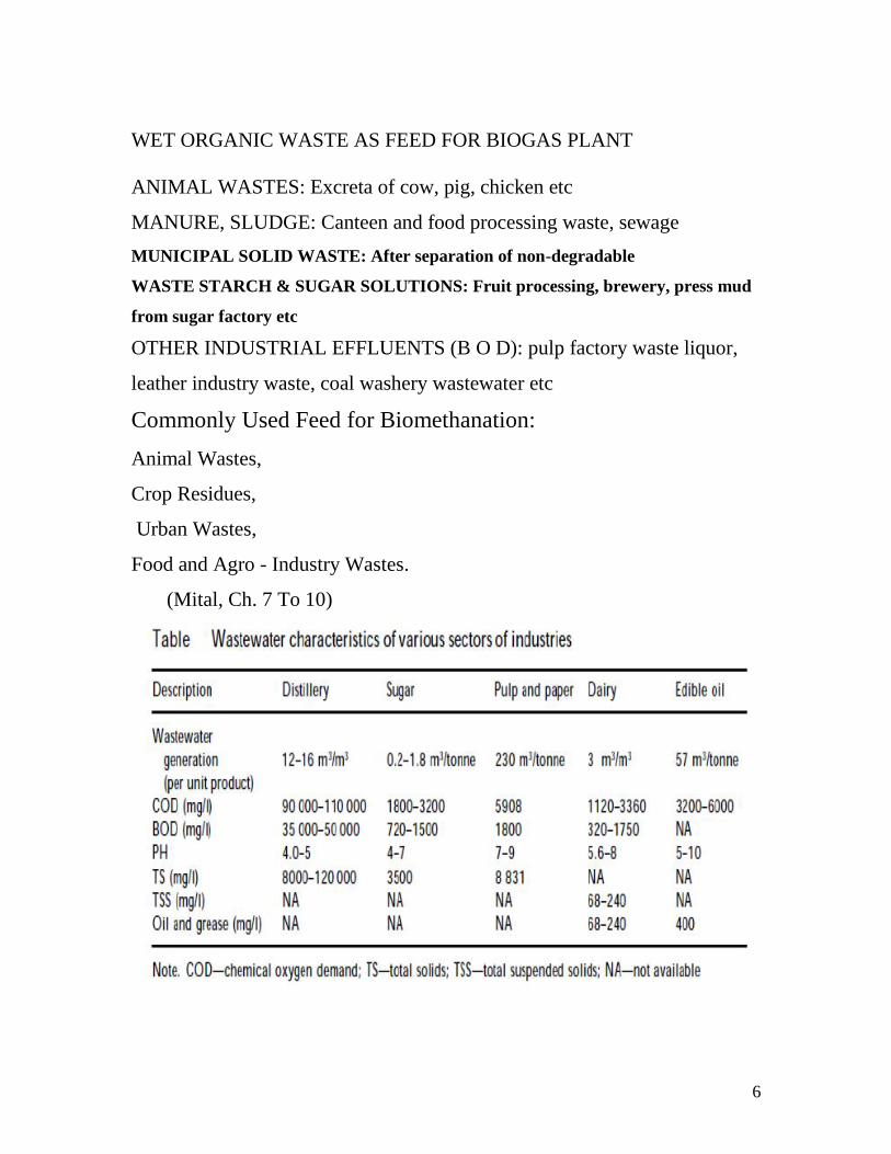
WET ORGANIC WASTE AS FEED FOR BIOGAS PLANT
ANIMAL WASTES: Excreta of cow, pig, chicken etc
MANURE, SLUDGE: Canteen and food processing waste, sewage
MUNICIPAL SOLID WASTE: After separation of non-degradable
WASTE STARCH & SUGAR SOLUTIONS: Fruit processing, brewery, press mud
from sugar factory etc
OTHER INDUSTRIAL EFFLUENTS (B O D): pulp factory waste liquor,
leather industry waste, coal washery wastewater etc
Commonly Used Feed for Biomethanation:
Animal Wastes,
Crop Residues,
Urban Wastes,
Food and Agro - Industry Wastes.
(Mital, Ch. 7 To 10)
7
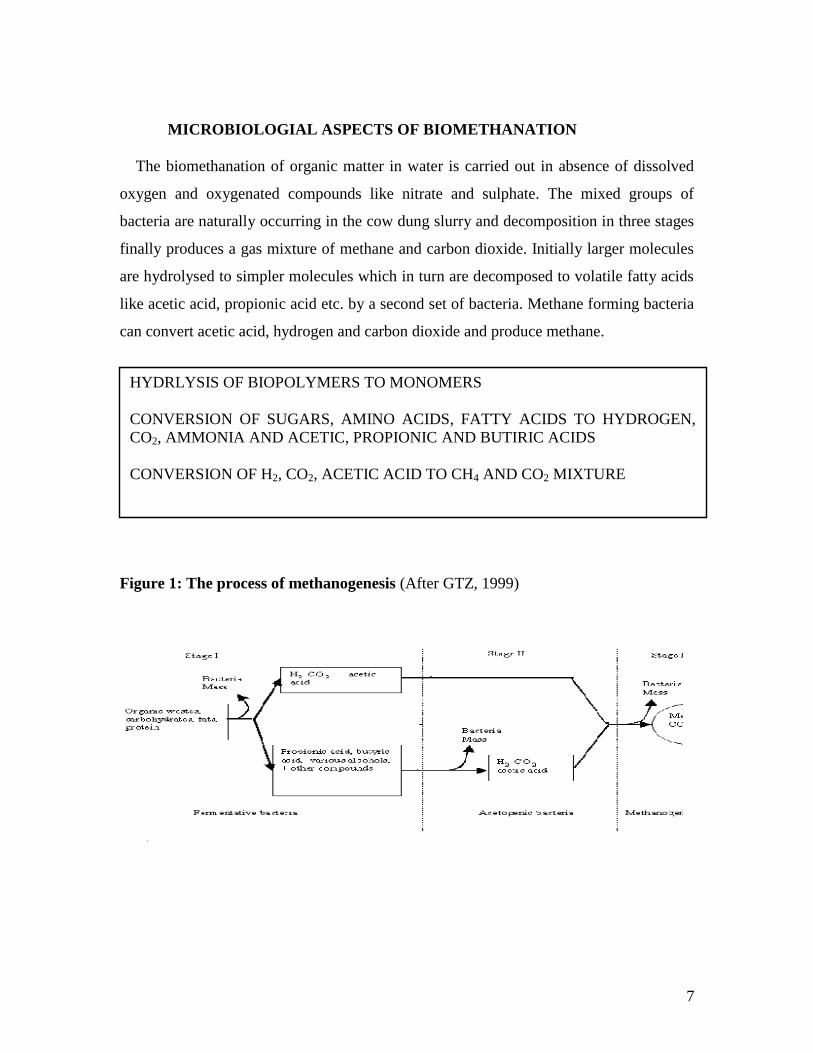
MICROBIOLOGIAL ASPECTS OF BIOMETHANATION
The biomethanation of organic matter in water is carried out in absence of dissolved
oxygen and oxygenated compounds like nitrate and sulphate. The mixed groups of
bacteria are naturally occurring in the cow dung slurry and decomposition in three stages
finally produces a gas mixture of methane and carbon dioxide. Initially larger molecules
are hydrolysed to simpler molecules which in turn are decomposed to volatile fatty acids
like acetic acid, propionic acid etc. by a second set of bacteria. Methane forming bacteria
can convert acetic acid, hydrogen and carbon dioxide and produce methane.
Figure 1: The process of methanogenesis (After GTZ, 1999)
HYDRLYSIS OF BIOPOLYMERS TO MONOMERS
CONVERSION OF SUGARS, AMINO ACIDS, FATTY ACIDS TO HYDROGEN,
CO2, AMMONIA AND ACETIC, PROPIONIC AND BUTIRIC ACIDS
CONVERSION OF H2, CO2, ACETIC ACID TO CH4 AND CO2 MIXTURE
8
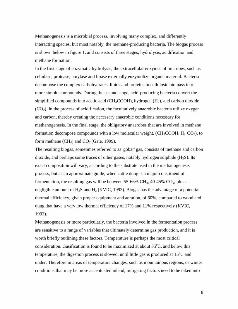
Methanogenesis is a microbial process, involving many complex, and differently
interacting species, but most notably, the methane-producing bacteria. The biogas process
is shown below in figure 1, and consists of three stages; hydrolysis, acidification and
methane formation.
In the first stage of enzymatic hydrolysis, the extracellular enzymes of microbes, such as
cellulase, protease, amylase and lipase externally enzymolize organic material. Bacteria
decompose the complex carbohydrates, lipids and proteins in cellulosic biomass into
more simple compounds. During the second stage, acid-producing bacteria convert the
simplified compounds into acetic acid (CH3COOH), hydrogen (H2), and carbon dioxide
(CO2). In the process of acidification, the facultatively anaerobic bacteria utilize oxygen
and carbon, thereby creating the necessary anaerobic conditions necessary for
methanogenesis. In the final stage, the obligatory anaerobes that are involved in methane
formation decompose compounds with a low molecular weight, (CH3COOH, H2, CO2), to
form methane (CH4) and CO2 (Gate, 1999).
The resulting biogas, sometimes referred to as 'gobar' gas, consists of methane and carbon
dioxide, and perhaps some traces of other gases, notably hydrogen sulphide (H2S). Its
exact composition will vary, according to the substrate used in the methanogenesis
process, but as an approximate guide, when cattle dung is a major constituent of
fermentation, the resulting gas will be between 55-66% CH4, 40-45% CO2, plus a
negligible amount of H2S and H2 (KVIC, 1993). Biogas has the advantage of a potential
thermal efficiency, given proper equipment and aeration, of 60%, compared to wood and
dung that have a very low thermal efficiency of 17% and 11% respectively (KVIC,
1993).
Methanogenesis or more particularly, the bacteria involved in the fermentation process
are sensitive to a range of variables that ultimately determine gas production, and it is
worth briefly outlining these factors. Temperature is perhaps the most critical
consideration. Gasification is found to be maximized at about 35oC, and below this
temperature, the digestion process is slowed, until little gas is produced at 15oC and
under. Therefore in areas of temperature changes, such as mountainous regions, or winter
conditions that may be more accentuated inland, mitigating factors need to be taken into
9
account, such as increased insulation (Kalia, 1988), or the addition of solar heaters to
maintain temperatures (Lichtman, 1983).
Loading rate and retention period of material are also important considerations. In the
KVIC model, retention ranges between 30-55 days, depending upon climatic conditions,
and will decrease if loaded with more than its rated capacity (which may result in
imperfectly digested slurry). KVIC state that maximum gas production occurs during the
first four weeks, before tapering off, therefore a plant should be designed for a retention
that exploits this feature. Retention period is found to reduce if temperatures are raised, or
more nutrients are added to the digester. Human excreta, due to its high nutrient content,
needs no more than 30 days retention in biogas plants (KVIC, 1983).
Various factors such as biogas potential of feedstock, design of digester, inoculum, nature
of substrate, pH, temperature, loading rate, hydraulic retention time (HRT), C : N ratio,
volatile fatty acids (VFA), etc. influence the biogas production.
Meher et al. reported that the performance of floating dome biogas plant was better than
the fixed dome biogas plant, showing an increase in biogas production by 11.3 per cent,
which was statistically significant. Furthermore, the observed reduction in biogas yield
was due to the loss of gas from the slurry-balancing chambers of fixed dome plant.
Dhevagi et al. used different feedstocks like cow dung, buffalo dung, dry animal waste,
stray cattle dung, goat waste, and poultry droppings for their biomethanation potential
and observed that poultry droppings showed higher gas production. Earlier Yeole and
Ranade compared the rates of biogas yield from pig dung-fed and cattle dung-fed
digesters and reported that the biogas yield was higher in the former. They attributed this
higher biogas yield to the presence of native microflora in the dung. Shivraj and
Seenayya reported that digesters fed with 8 per cent TS of poultry waste gave better
biogas yield, and attributed the lower yield of biogas at higher TS levels to high ammonia
content of the slurry
10
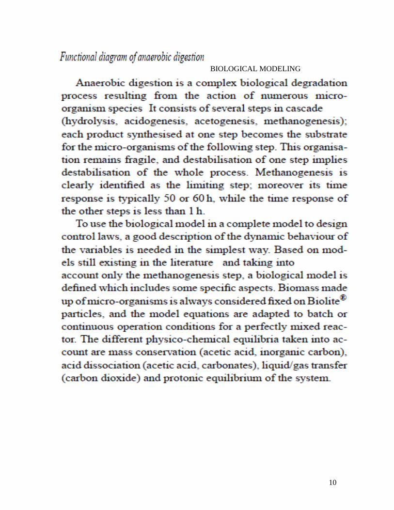
BIOLOGICAL MODELING
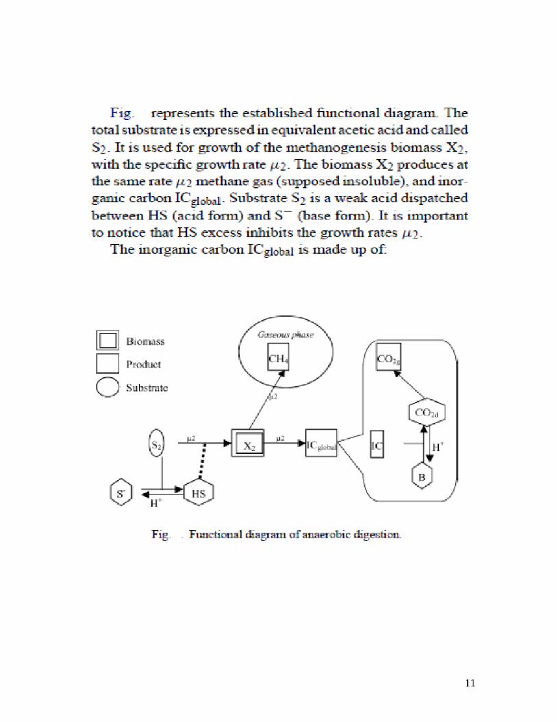
11
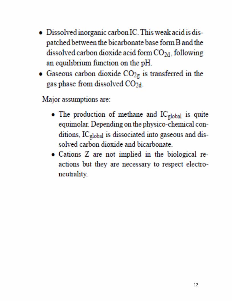
12
13
The modeling and its simulation referred to is from the following paper:
14
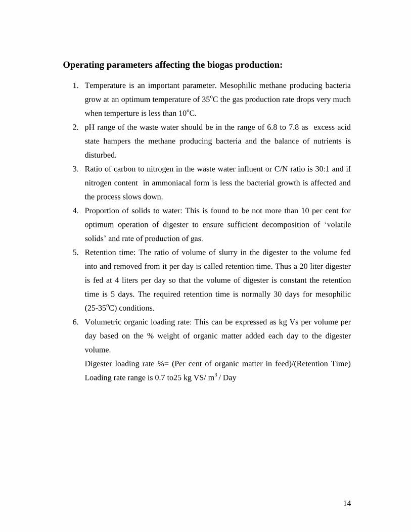
Operating parameters affecting the biogas production:
1. Temperature is an important parameter. Mesophilic methane producing bacteria
grow at an optimum temperature of 35oC the gas production rate drops very much
when temperture is less than 10oC.
2. pH range of the waste water should be in the range of 6.8 to 7.8 as excess acid
state hampers the methane producing bacteria and the balance of nutrients is
disturbed.
3. Ratio of carbon to nitrogen in the waste water influent or C/N ratio is 30:1 and if
nitrogen content in ammoniacal form is less the bacterial growth is affected and
the process slows down.
4. Proportion of solids to water: This is found to be not more than 10 per cent for
optimum operation of digester to ensure sufficient decomposition of „volatile
solids‟ and rate of production of gas.
5. Retention time: The ratio of volume of slurry in the digester to the volume fed
into and removed from it per day is called retention time. Thus a 20 liter digester
is fed at 4 liters per day so that the volume of digester is constant the retention
time is 5 days. The required retention time is normally 30 days for mesophilic
(25-35oC) conditions.
6. Volumetric organic loading rate: This can be expressed as kg Vs per volume per
day based on the % weight of organic matter added each day to the digester
volume.
Digester loading rate %= (Per cent of organic matter in feed)/(Retention Time)
Loading rate range is 0.7 to25 kg VS/ m3
/ Day
15
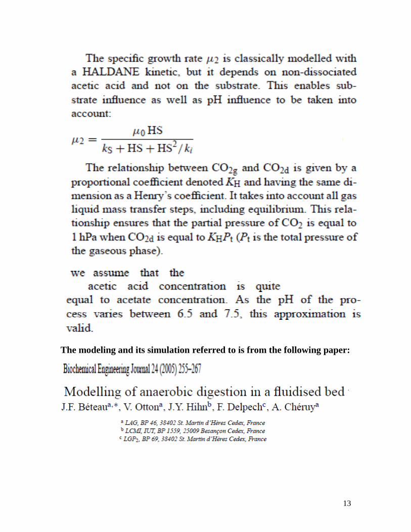
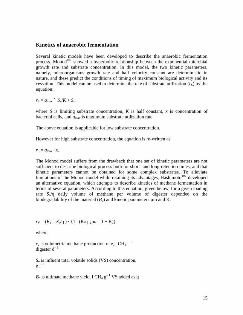
Kinetics of anaerobic fermentation
Several kinetic models have been developed to describe the anaerobic fermentation
process. Monod101
showed a hyperbolic relationship between the exponential microbial
growth rate and substrate concentration. In this model, the two kinetic parameters,
namely, microorganisms growth rate and half velocity constant are deterministic in
nature, and these predict the conditions of timing of maximum biological activity and its
cessation. This model can be used to determine the rate of substrate utilization (rS) by the
equation:
rS = qmax ´ Sx/K + S,
where S is limiting substrate concentration, K is half constant, x is concentration of
bacterial cells, and qmax is maximum substrate utilization rate.
The above equation is applicable for low substrate concentration.
However for high substrate concentration, the equation is re-written as:
rS = qmax · x.
The Monod model suffers from the drawback that one set of kinetic parameters are not
sufficient to describe biological process both for short- and long-retention times, and that
kinetic parameters cannot be obtained for some complex substrates. To alleviate
limitations of the Monod model while retaining its advantages, Hashimoto102
developed
an alternative equation, which attempts to describe kinetics of methane fermentation in
terms of several parameters. According to this equation, given below, for a given loading
rate So/q daily volume of methane per volume of digester depended on the
biodegradability of the material (Bo) and kinetic parameters µm and K.
rV = (Bo ´ So/q ) · {1– (K/q µm – 1 + K)}
where,
rv is volumetric methane production rate, l CH4 l– 1
digester d– 1
So is influent total volatile solids (VS) concentration,
g l– 1
Bo is ultimate methane yield, l CH4 g– 1
VS added as q
16
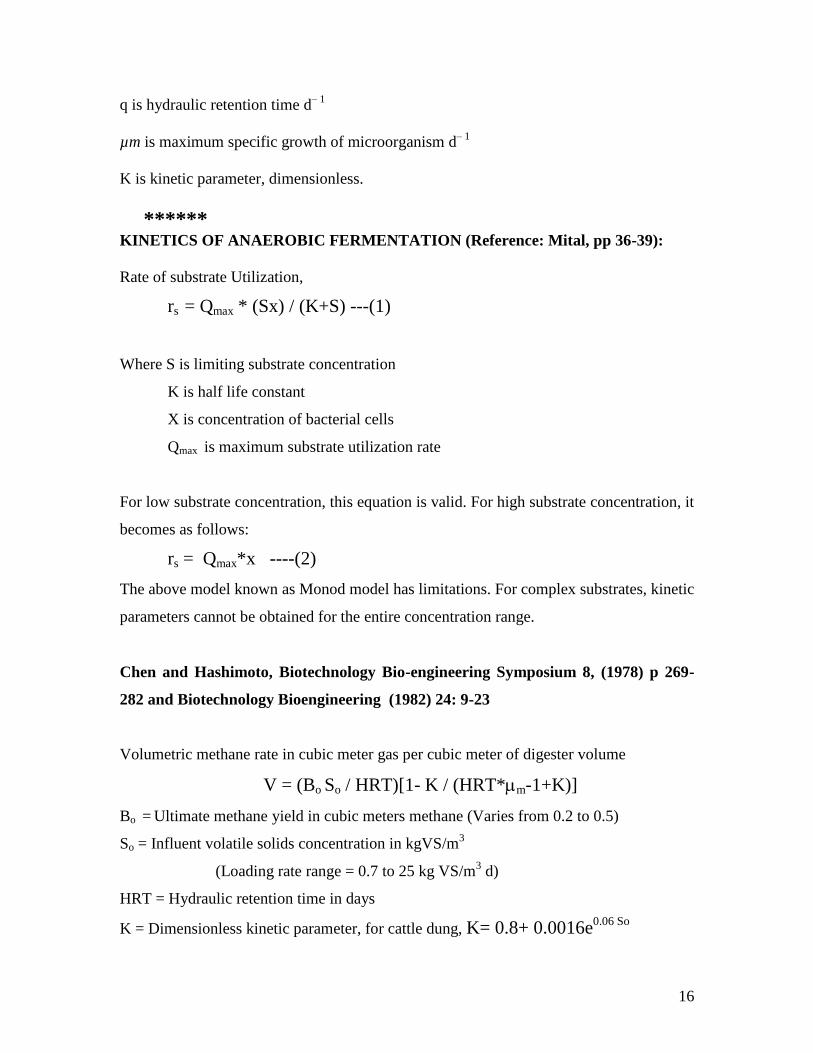
q is hydraulic retention time d– 1
µm is maximum specific growth of microorganism d– 1
K is kinetic parameter, dimensionless.
****** KINETICS OF ANAEROBIC FERMENTATION (Reference: Mital, pp 36-39):
Rate of substrate Utilization,
rs = Qmax * (Sx) / (K+S) ---(1)
Where S is limiting substrate concentration
K is half life constant
X is concentration of bacterial cells
Qmax is maximum substrate utilization rate
For low substrate concentration, this equation is valid. For high substrate concentration, it
becomes as follows:
rs = Qmax*x ----(2)
The above model known as Monod model has limitations. For complex substrates, kinetic
parameters cannot be obtained for the entire concentration range.
Chen and Hashimoto, Biotechnology Bio-engineering Symposium 8, (1978) p 269-
282 and Biotechnology Bioengineering (1982) 24: 9-23
Volumetric methane rate in cubic meter gas per cubic meter of digester volume
V = (Bo So / HRT)[1- K / (HRT*m-1+K)]
Bo = Ultimate methane yield in cubic meters methane (Varies from 0.2 to 0.5)
So = Influent volatile solids concentration in kgVS/m3
(Loading rate range = 0.7 to 25 kg VS/m3 d)
HRT = Hydraulic retention time in days
K = Dimensionless kinetic parameter, for cattle dung, K= 0.8+ 0.0016e0.06 So
17
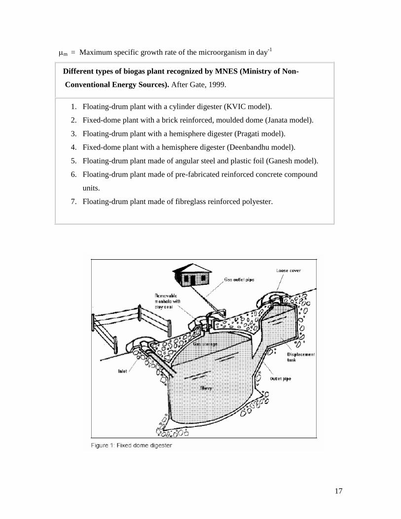
m = Maximum specific growth rate of the microorganism in day-1
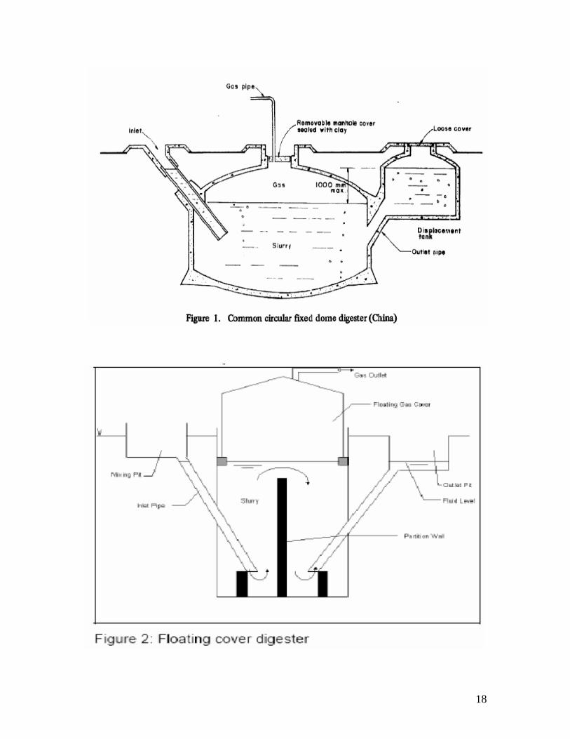
Different types of biogas plant recognized by MNES (Ministry of Non-
Conventional Energy Sources). After Gate, 1999.
1. Floating-drum plant with a cylinder digester (KVIC model).
2. Fixed-dome plant with a brick reinforced, moulded dome (Janata model).
3. Floating-drum plant with a hemisphere digester (Pragati model).
4. Fixed-dome plant with a hemisphere digester (Deenbandhu model).
5. Floating-drum plant made of angular steel and plastic foil (Ganesh model).
6. Floating-drum plant made of pre-fabricated reinforced concrete compound
units.
7. Floating-drum plant made of fibreglass reinforced polyester.
18
19
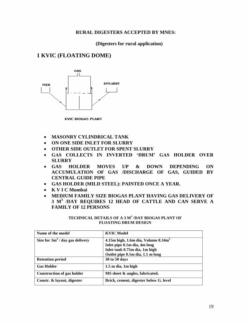
RURAL DIGESTERS ACCEPTED BY MNES:
(Digesters for rural application)
1 KVIC (FLOATING DOME)
MASONRY CYLINDRICAL TANK
ON ONE SIDE INLET FOR SLURRY
OTHER SIDE OUTLET FOR SPENT SLURRY
GAS COLLECTS IN INVERTED ‘DRUM’ GAS HOLDER OVER
SLURRY
GAS HOLDER MOVES UP & DOWN DEPENDING ON
ACCUMULATION OF GAS /DISCHARGE OF GAS, GUIDED BY
CENTRAL GUIDE PIPE
GAS HOLDER (MILD STEEL): PAINTED ONCE A YEAR.
K V I C Mumbai
MEDIUM FAMILY SIZE BIOGAS PLANT HAVING GAS DELIVERY OF
3 M3 /DAY REQUIRES 12 HEAD OF CATTLE AND CAN SERVE A
FAMILY OF 12 PERSONS
TECHNICAL DETAILS OF A 3 M
3 /DAY BIOGAS PLANT OF
FLOATING DRUM DESIGN
Name of the model KVIC Model
Size for 3m3 / day gas delivery 4.15m high, 1.6m dia, Volume 8.34m
3
Inlet pipe 0.1m dia, 4m long
Inlet tank 0.75m dia, 1m high
Outlet pipe 0.1m dia, 1.1 m long
Retention period 30 to 50 days
Gas Holder 1.5 m dia, 1m high
Construction of gas holder MS sheet & angles, fabricated.
Constr. & layout, digester Brick, cement, digester below G. level
20
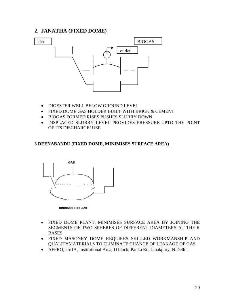
2. JANATHA (FIXED DOME)
DIGESTER WELL BELOW GROUND LEVEL
FIXED DOME GAS HOLDER BUILT WITH BRICK & CEMENT
BIOGAS FORMED RISES PUSHES SLURRY DOWN
DISPLACED SLURRY LEVEL PROVIDES PRESSURE-UPTO THE POINT
OF ITS DISCHARGE/ USE
3 DEENABANDU (FIXED DOME, MINIMISES SURFACE AREA)
FIXED DOME PLANT, MINIMISES SURFACE AREA BY JOINING THE
SEGMENTS OF TWO SPHERES OF DIFFERENT DIAMETERS AT THEIR
BASES
FIXED MASONRY DOME REQUIRES SKILLED WORKMANSHIP AND
QUALITYMATERIALS TO ELIMINATE CHANCE OF LEAKAGE OF GAS
AFPRO, 25/1A, Institutional Area, D block, Panka Rd, Janakpury, N.Delhi.
BIOGAS inlet
outlet
21
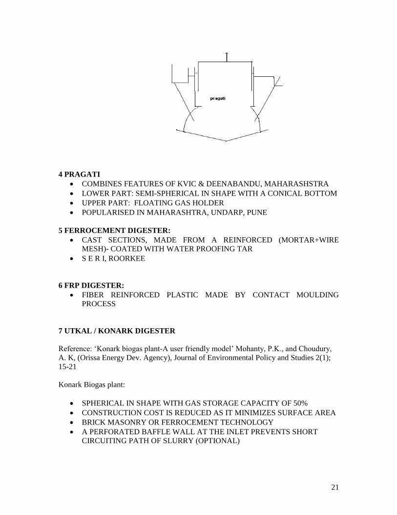
4 PRAGATI
COMBINES FEATURES OF KVIC & DEENABANDU, MAHARASHSTRA
LOWER PART: SEMI-SPHERICAL IN SHAPE WITH A CONICAL BOTTOM
UPPER PART: FLOATING GAS HOLDER
POPULARISED IN MAHARASHTRA, UNDARP, PUNE
5 FERROCEMENT DIGESTER:
CAST SECTIONS, MADE FROM A REINFORCED (MORTAR+WIRE
MESH)- COATED WITH WATER PROOFING TAR
S E R I, ROORKEE
6 FRP DIGESTER:
FIBER REINFORCED PLASTIC MADE BY CONTACT MOULDING
PROCESS
7 UTKAL / KONARK DIGESTER
Reference: „Konark biogas plant-A user friendly model‟ Mohanty, P.K., and Choudury,
A. K, (Orissa Energy Dev. Agency), Journal of Environmental Policy and Studies 2(1);
15-21
Konark Biogas plant:
SPHERICAL IN SHAPE WITH GAS STORAGE CAPACITY OF 50%
CONSTRUCTION COST IS REDUCED AS IT MINIMIZES SURFACE AREA
BRICK MASONRY OR FERROCEMENT TECHNOLOGY
A PERFORATED BAFFLE WALL AT THE INLET PREVENTS SHORT
CIRCUITING PATH OF SLURRY (OPTIONAL)
22
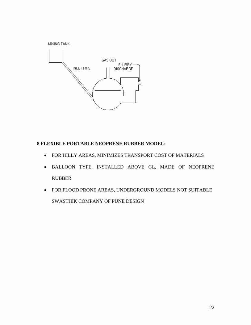
8 FLEXIBLE PORTABLE NEOPRENE RUBBER MODEL:
FOR HILLY AREAS, MINIMIZES TRANSPORT COST OF MATERIALS
BALLOON TYPE, INSTALLED ABOVE GL, MADE OF NEOPRENE
RUBBER
FOR FLOOD PRONE AREAS, UNDERGROUND MODELS NOT SUITABLE
SWASTHIK COMPANY OF PUNE DESIGN
23
24
25
HIGH RATE DIGESTERS FOR WASTE WATER TREATMENT:
1. ANAEROBIC FILTER (UPFLOW and DOWNFLOW)
2. UPFLOW ANAEROBIC SLUDGE BLANKET DIGESTER( UASB)
3. ANAEROBIC LIQUID FLUIDISED/ EXPANDED BED DIGESTER
4. ANAEROBIC ROTATING DISC CONTACTING DIGESTER
5. ANAEROBIC MEMBRANE DIGESTER
6. ANAEROBIC CONTACT DIGESTER
Effluent Treatment & Disposal: I Ch. E, U.K., Symposium Series No96,
1986., P 137-147, Application of anaerobic biotechnology to waste
treatment and energy production Anderson & Saw.
Energy & Environment Monitor, 12(1) 45- 51, „Biomethanation
Technologies in industrial water pollution Control‟ A.Gangagni Rao, Pune.
Techniques for enhancing biogas production
Different methods used to enhance biogas production can be classified into
the following categories:
(i) Use of additives.
(ii) Recycling of slurry and slurry filtrate.
(iii) Variation in operational parameters like temperature, Hydraulic
retention time (HRT) and particle size of the substrate.
(iv) Use of fixed film / biofilters.
26
HIGH RATE DIGESTERS FOR WASTE WATER TREATMENT:
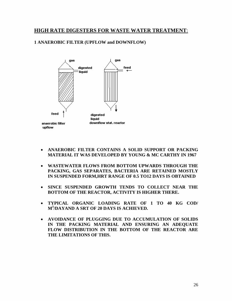
1 ANAEROBIC FILTER (UPFLOW and DOWNFLOW)
ANAEROBIC FILTER CONTAINS A SOLID SUPPORT OR PACKING
MATERIAL IT WAS DEVELOPED BY YOUNG & MC CARTHY IN 1967
WASTEWATER FLOWS FROM BOTTOM UPWARDS THROUGH THE
PACKING, GAS SEPARATES, BACTERIA ARE RETAINED MOSTLY
IN SUSPENDED FORM,HRT RANGE OF 0.5 TO12 DAYS IS OBTAINED
SINCE SUSPENDED GROWTH TENDS TO COLLECT NEAR THE
BOTTOM OF THE REACTOR, ACTIVITY IS HIGHER THERE.
TYPICAL ORGANIC LOADING RATE OF 1 TO 40 KG COD/
M3/DAYAND A SRT OF 20 DAYS IS ACHIEVED.
AVOIDANCE OF PLUGGING DUE TO ACCUMULATION OF SOLIDS
IN THE PACKING MATERIAL AND ENSURING AN ADEQUATE
FLOW DISTRIBUTION IN THE BOTTOM OF THE REACTOR ARE
THE LIMITATIONS OF THIS.
27
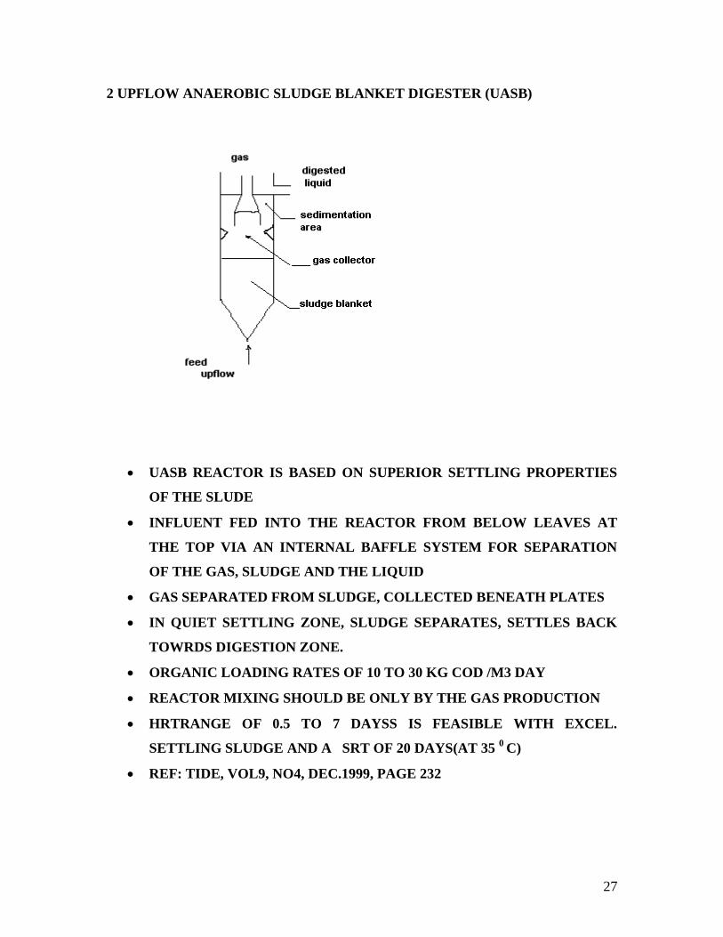
2 UPFLOW ANAEROBIC SLUDGE BLANKET DIGESTER (UASB)
UASB REACTOR IS BASED ON SUPERIOR SETTLING PROPERTIES
OF THE SLUDE
INFLUENT FED INTO THE REACTOR FROM BELOW LEAVES AT
THE TOP VIA AN INTERNAL BAFFLE SYSTEM FOR SEPARATION
OF THE GAS, SLUDGE AND THE LIQUID
GAS SEPARATED FROM SLUDGE, COLLECTED BENEATH PLATES
IN QUIET SETTLING ZONE, SLUDGE SEPARATES, SETTLES BACK
TOWRDS DIGESTION ZONE.
ORGANIC LOADING RATES OF 10 TO 30 KG COD /M3 DAY
REACTOR MIXING SHOULD BE ONLY BY THE GAS PRODUCTION
HRTRANGE OF 0.5 TO 7 DAYSS IS FEASIBLE WITH EXCEL.
SETTLING SLUDGE AND A SRT OF 20 DAYS(AT 35 0
C)
REF: TIDE, VOL9, NO4, DEC.1999, PAGE 232
28
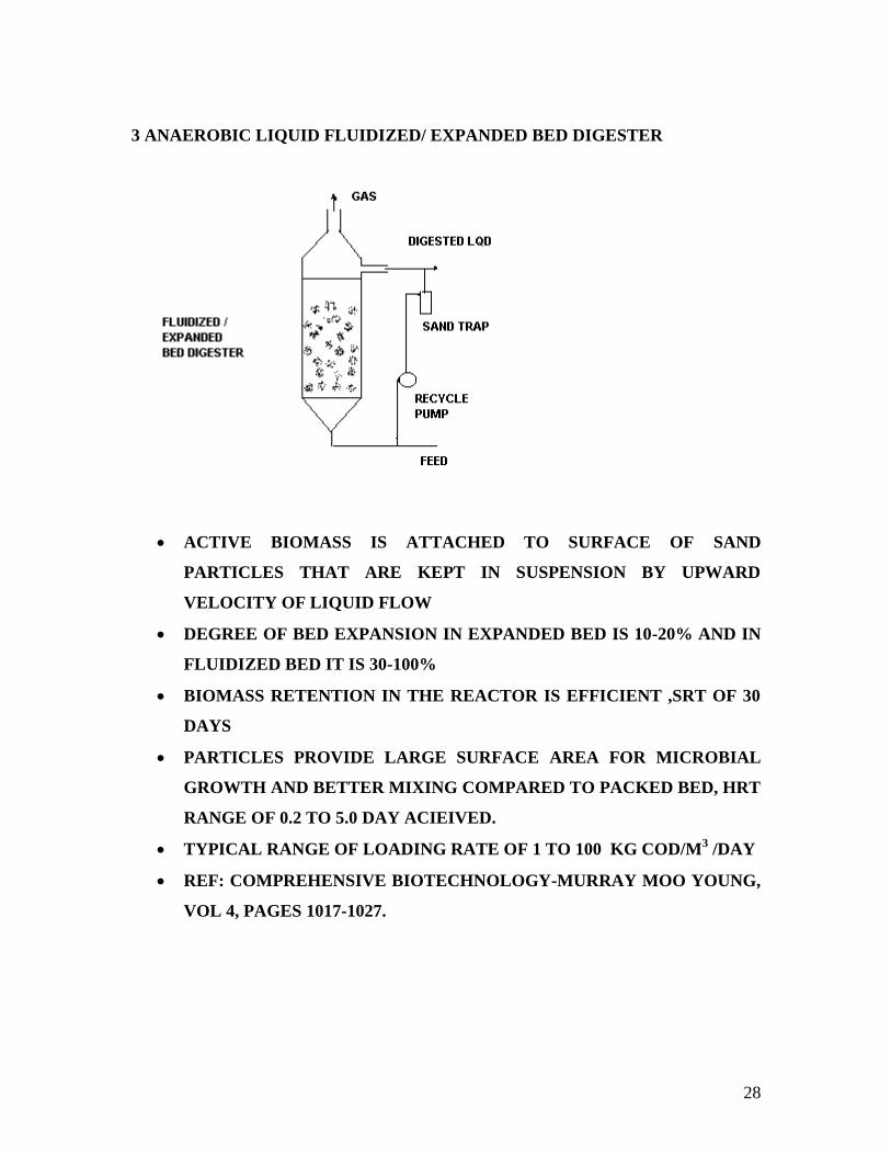
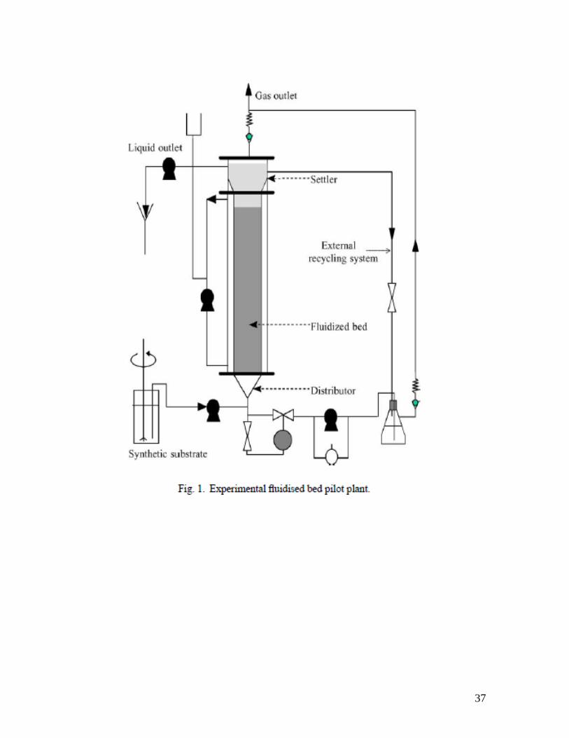
3 ANAEROBIC LIQUID FLUIDIZED/ EXPANDED BED DIGESTER
ACTIVE BIOMASS IS ATTACHED TO SURFACE OF SAND
PARTICLES THAT ARE KEPT IN SUSPENSION BY UPWARD
VELOCITY OF LIQUID FLOW
DEGREE OF BED EXPANSION IN EXPANDED BED IS 10-20% AND IN
FLUIDIZED BED IT IS 30-100%
BIOMASS RETENTION IN THE REACTOR IS EFFICIENT ,SRT OF 30
DAYS
PARTICLES PROVIDE LARGE SURFACE AREA FOR MICROBIAL
GROWTH AND BETTER MIXING COMPARED TO PACKED BED, HRT
RANGE OF 0.2 TO 5.0 DAY ACIEIVED.
TYPICAL RANGE OF LOADING RATE OF 1 TO 100 KG COD/M3 /DAY
REF: COMPREHENSIVE BIOTECHNOLOGY-MURRAY MOO YOUNG,
VOL 4, PAGES 1017-1027.
29
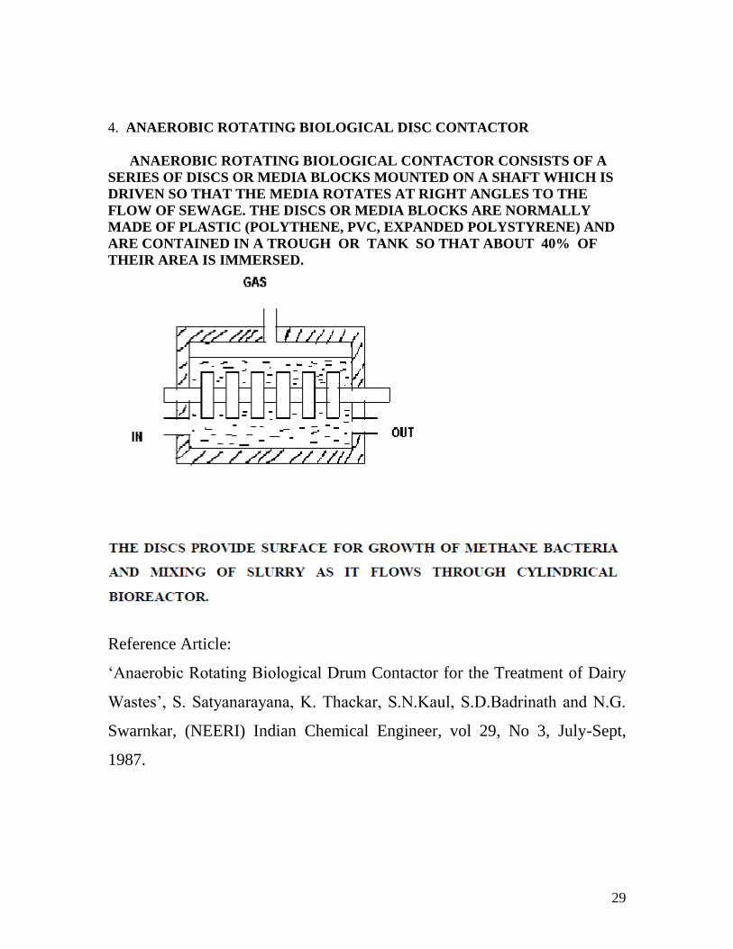
4. ANAEROBIC ROTATING BIOLOGICAL DISC CONTACTOR
ANAEROBIC ROTATING BIOLOGICAL CONTACTOR CONSISTS OF A
SERIES OF DISCS OR MEDIA BLOCKS MOUNTED ON A SHAFT WHICH IS
DRIVEN SO THAT THE MEDIA ROTATES AT RIGHT ANGLES TO THE
FLOW OF SEWAGE. THE DISCS OR MEDIA BLOCKS ARE NORMALLY
MADE OF PLASTIC (POLYTHENE, PVC, EXPANDED POLYSTYRENE) AND
ARE CONTAINED IN A TROUGH OR TANK SO THAT ABOUT 40% OF
THEIR AREA IS IMMERSED.
Reference Article:
„Anaerobic Rotating Biological Drum Contactor for the Treatment of Dairy
Wastes‟, S. Satyanarayana, K. Thackar, S.N.Kaul, S.D.Badrinath and N.G.
Swarnkar, (NEERI) Indian Chemical Engineer, vol 29, No 3, July-Sept,
1987.
30
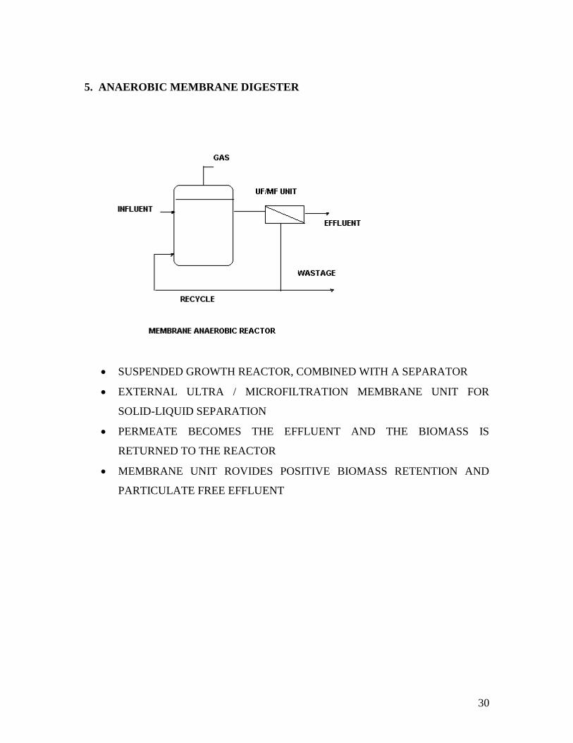
5. ANAEROBIC MEMBRANE DIGESTER
SUSPENDED GROWTH REACTOR, COMBINED WITH A SEPARATOR
EXTERNAL ULTRA / MICROFILTRATION MEMBRANE UNIT FOR
SOLID-LIQUID SEPARATION
PERMEATE BECOMES THE EFFLUENT AND THE BIOMASS IS
RETURNED TO THE REACTOR
MEMBRANE UNIT ROVIDES POSITIVE BIOMASS RETENTION AND
PARTICULATE FREE EFFLUENT
31
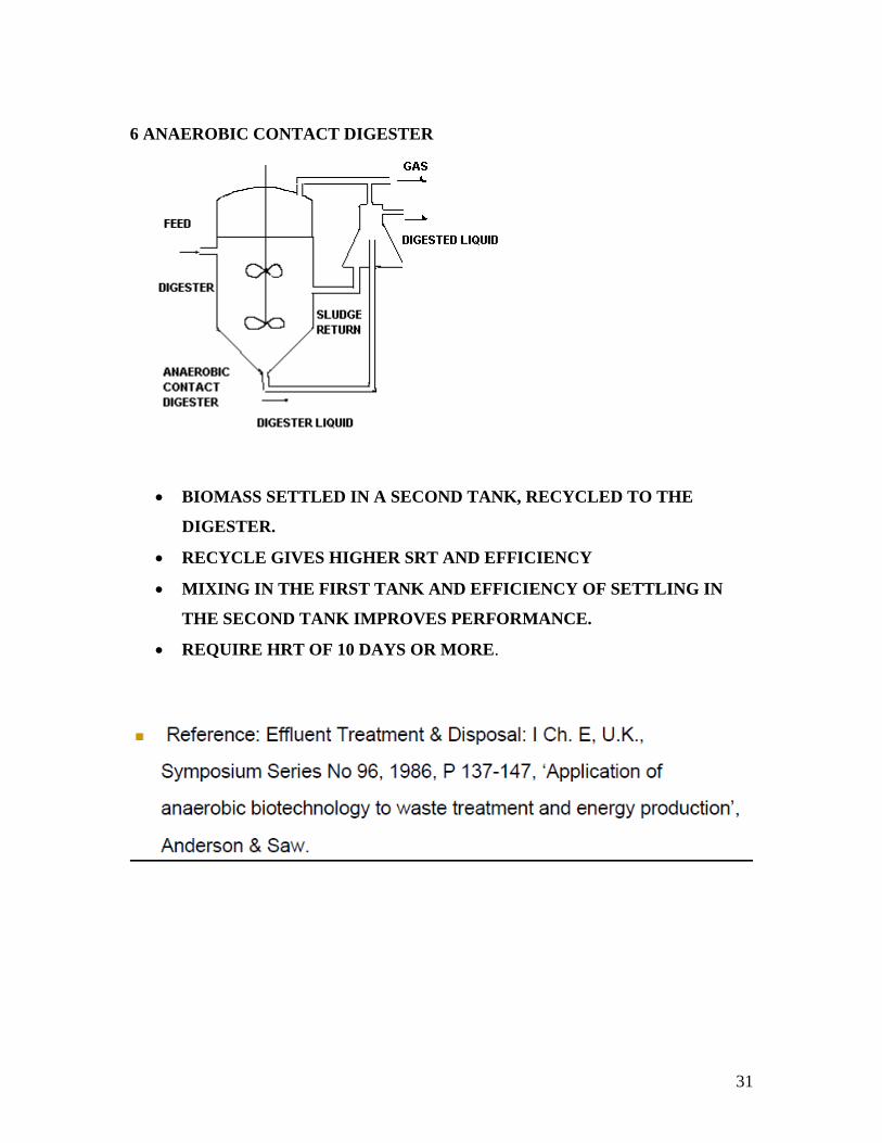
6 ANAEROBIC CONTACT DIGESTER
BIOMASS SETTLED IN A SECOND TANK, RECYCLED TO THE
DIGESTER.
RECYCLE GIVES HIGHER SRT AND EFFICIENCY
MIXING IN THE FIRST TANK AND EFFICIENCY OF SETTLING IN
THE SECOND TANK IMPROVES PERFORMANCE.
REQUIRE HRT OF 10 DAYS OR MORE.
32
33
34
Comments on Rural biogas plants:
Biogas has shown to be a useful component in the rural economy in India,
though its application is logistically difficult. Ill-co-ordinated dissemination
has led to high rates of non-functioning plants, and may endanger further
uptake, as such, its status as a fuel remains marginal.
Participation in biogas technology varies across socio-economic groups, and
across regions. Despite a well-intentioned attempt to cater for the energy
needs of rural India, and particularly the poor, as defined by 'scheduled caste'
and 'scheduled tribe', the biogas programme has not appeared to meet these
needs on any meaningful scale, through insurmountable constraints
associated with their very marginality, paradoxically. Limited success has
occurred in other agricultural groups.
Further, the essential 'commodification' of dung, which has occurred since
the introduction of biogas systems may impact detrimentally upon the
poorest families, who may experience a scarcity of the fuel once gathered for
free. The need to provide rural India with a viable and sustainable source of
fuel has perhaps never been more urgent, yet curiously, this is not reflected
in current literature, as biogas seemingly drops out of journals in the 1990's,
as a subject to be written about. Therefore, the very current situation
regarding the status of biogas technology in India is unknown, though
dissemination is still being undertaken. Bapu's (Gandhi's) dream therefore
remains largely unrealized, though 'small steps' may have been achieved.
35
1. What properties of biogas have to be improved before it is used
as an engine fuel?
2. Write short notes on (i) Feedstock for biogas, (ii) Dry and wet
fermentation, (iii) Microbial and biochemical aspects.
3. Discuss the operating parameters for biogas production by
anaerobic digestion.
4. What criteria are applied in selecting a rural biogas plant of a
small family size?
5. Why biogas is not supplied in cylinders like LPG? Can we use
same stove for both?
6. Explain hydraulic and solid retention time for a fixed film biogas
digester.
7. In a flood prone area, what type of small biogas plant would
you use?
36
37