Biochemical Sensor Interface Circuits with Differential ...soc.inha.ac.kr/images/APCCA2012.pdf ·...
4
Biochemical Sensor Interface Circuits with Differential Difference Amplifier Shin-Il Lim, In-Sub Choi, Dept. of Electronics Engineering Seokyeong University Seoul, Korea [email protected] , [email protected] , Han-Ho Lee Dept. of Information and Communication Engineering Inha University Incheon, Korea [email protected] Abstract—A simple three-electrode CMOS interface system for electrochemical sensor is described. To maintain a constant potential between the reference electrode (RE) and working electrode (WE), only one differential difference amplifier (DDA) is exploited in this proposed design, while conventional sensor interface system requires at least 2 operational amplifiers and 2 resistors, or more than 3 operational amplifiers and 4 resistors for low voltage differential CMOS integrated interface circuits. The DDA with rail-to-rail design not only enables the full range operation to supply voltage but also provides simple interface system with small hardware and low power consumption. This new interface system was implemented in a 0.35um standard CMOS technology and experimentally verified. I. INTRODUCTION Electro-biochemical sensors are widely used in glucose monitoring, pH variation detection, protein classification, neurotransmitter sensing, oxygen concentration monitoring, dissolved molecules in liquid and toxic gas detection, etc. [1]- [9]. Interface circuits for biochemical sensor provide constant voltage to the sensor and detect the sensor current as the resistance of sensor varies by its electro-chemical status (concentration, type, etc) of solution. Amperometric potentiostat, one of the techniques in electro-biochemical analysis, is based on the chemical reaction of certain species that involves a gain of electron (oxidation) and/or a loss of electrons (reduction) while maintaining a characteristic potential. Two or three sensor electrodes are commonly used in amperometric measurement technique. To prevent the effect of the voltage loss that is caused by the resistance of the analyte solution, three-electrode potentiostat is usually preferred for accurate sensor measurement system. Recent in- vivo biochemical sensor, such as implantable glucose sensor and neuro-transmitters, needs a miniaturized potentiostat which can measure the small redox (reduction and oxidation) current of ~nA range while maintaining a certain redox potential. Reducing the signal path from sensor to the interface circuit is very important to reduce the noise and interfering signals. The best solution for this problem is to place the interface circuits and sensors on one small package or on one chip. A simple and new CMOS interface (potentiostat) circuit for biochemical sensor is proposed in this design. One amplifier without any passive components is enough to maintain the potential between the reference electrode (RE) and working electrode (WE). The Portable or disposable or implantable biosensor can be implemented with this small and robust interface circuits. More details are described in following sections. II. CONVENTIONAL BIOCHEMICAL SENSOR DESIGN Conventional amperometric potentiostat is shown in Fig. 1(a) [5] and it's fully differential version for wide swing in low voltage applications is in Fig. 1(b) [6]. If the gain of A2 is big enough and R1 and R2 have same values in Fig. 1(a), the source potential VSRC can be equal to the applied cell potential of VCELL to the sensor that has the Faradaic resistance of RFW, (VSRC = VCELL). This potential difference of VCELL between the reference electrode (RE) and working electrode (WE) induces an sensor reaction current that has the value of VCELL/RFW. This sensor reaction current can be measured by using trans- impedance amplifier (TIA) or by using charge based counting ADC. The fully differential implementation of conventional amperometric potentiostat shows larger dynamic range than single ended mode in low voltage application. Since the conventional amperometric potentiostat needs several op-amps and passive resistors for three electrode biochemical sensor system, it is vulnerable to mismatch, offset and noise. And it shows larger hardware consumption and larger power consumption than proposed simple CMOS interface (potentiostat) circuit for biochemical sensor. III. PROPOSED BIOCHEMICAL INTERFACE CIRCUITS Fig. 2 illustrates the architecture of proposed simple biochemical interface circuit. The proposed circuits consist of differential difference amplifier (DDA) and trans-impedance amplifier (TIA). This work supported by NRF and ETRI. 176 978-1-4577-1729-1/12/$26.00 ©2012 IEEE.
Transcript of Biochemical Sensor Interface Circuits with Differential ...soc.inha.ac.kr/images/APCCA2012.pdf ·...

Biochemical Sensor Interface Circuits with Differential Difference Amplifier
Shin-Il Lim, In-Sub Choi, Dept. of Electronics Engineering
Seokyeong University Seoul, Korea
[email protected], [email protected],
Han-Ho Lee Dept. of Information and Communication Engineering
Inha University Incheon, Korea
Abstract—A simple three-electrode CMOS interface system for electrochemical sensor is described. To maintain a constant potential between the reference electrode (RE) and working electrode (WE), only one differential difference amplifier (DDA) is exploited in this proposed design, while conventional sensor interface system requires at least 2 operational amplifiers and 2 resistors, or more than 3 operational amplifiers and 4 resistors for low voltage differential CMOS integrated interface circuits. The DDA with rail-to-rail design not only enables the full range operation to supply voltage but also provides simple interface system with small hardware and low power consumption. This new interface system was implemented in a 0.35um standard CMOS technology and experimentally verified.
I. INTRODUCTION Electro-biochemical sensors are widely used in glucose
monitoring, pH variation detection, protein classification, neurotransmitter sensing, oxygen concentration monitoring, dissolved molecules in liquid and toxic gas detection, etc. [1]-[9]. Interface circuits for biochemical sensor provide constant voltage to the sensor and detect the sensor current as the resistance of sensor varies by its electro-chemical status (concentration, type, etc) of solution. Amperometric potentiostat, one of the techniques in electro-biochemical analysis, is based on the chemical reaction of certain species that involves a gain of electron (oxidation) and/or a loss of electrons (reduction) while maintaining a characteristic potential. Two or three sensor electrodes are commonly used in amperometric measurement technique. To prevent the effect of the voltage loss that is caused by the resistance of the analyte solution, three-electrode potentiostat is usually preferred for accurate sensor measurement system. Recent in-vivo biochemical sensor, such as implantable glucose sensor and neuro-transmitters, needs a miniaturized potentiostat which can measure the small redox (reduction and oxidation) current of ~nA range while maintaining a certain redox potential. Reducing the signal path from sensor to the interface circuit is very important to reduce the noise and interfering signals. The best solution for this problem is to place the
interface circuits and sensors on one small package or on one chip.
A simple and new CMOS interface (potentiostat) circuit for biochemical sensor is proposed in this design. One amplifier without any passive components is enough to maintain the potential between the reference electrode (RE) and working electrode (WE). The Portable or disposable or implantable biosensor can be implemented with this small and robust interface circuits. More details are described in following sections.
II. CONVENTIONAL BIOCHEMICAL SENSOR DESIGN Conventional amperometric potentiostat is shown in Fig.
1(a) [5] and it's fully differential version for wide swing in low voltage applications is in Fig. 1(b) [6]. If the gain of A2 is big enough and R1 and R2 have same values in Fig. 1(a), the source potential VSRC can be equal to the applied cell potential of VCELL to the sensor that has the Faradaic resistance of RFW, (VSRC = VCELL). This potential difference of VCELL between the reference electrode (RE) and working electrode (WE) induces an sensor reaction current that has the value of VCELL/RFW. This sensor reaction current can be measured by using trans-impedance amplifier (TIA) or by using charge based counting ADC. The fully differential implementation of conventional amperometric potentiostat shows larger dynamic range than single ended mode in low voltage application.
Since the conventional amperometric potentiostat needs several op-amps and passive resistors for three electrode biochemical sensor system, it is vulnerable to mismatch, offset and noise. And it shows larger hardware consumption and larger power consumption than proposed simple CMOS interface (potentiostat) circuit for biochemical sensor.
III. PROPOSED BIOCHEMICAL INTERFACE CIRCUITS Fig. 2 illustrates the architecture of proposed simple
biochemical interface circuit. The proposed circuits consist of differential difference amplifier (DDA) and trans-impedance amplifier (TIA).
This work supported by NRF and ETRI.
176978-1-4577-1729-1/12/$26.00 ©2012 IEEE.
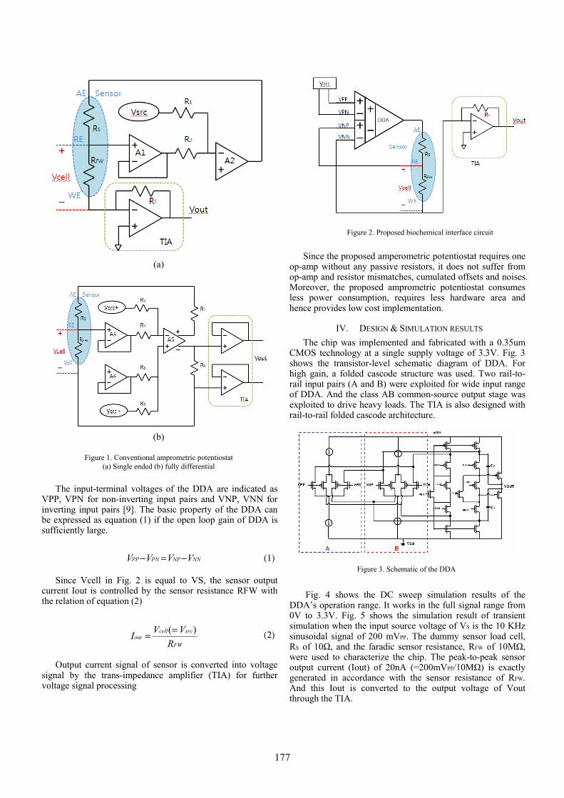
The input-terminal voltages of the DDA are indicated as
VPP, VPN for non-inverting input pairs and VNP, VNN for inverting input pairs [9]. The basic property of the DDA can be expressed as equation (1) if the open loop gain of DDA is sufficiently large.
NNNPPNPP VVVV −=− (1)
Since Vcell in Fig. 2 is equal to VS, the sensor output current Iout is controlled by the sensor resistance RFW with the relation of equation (2)
FW
srccellout
RVVI )(== (2)
Output current signal of sensor is converted into voltage signal by the trans-impedance amplifier (TIA) for further voltage signal processing
Since the proposed amperometric potentiostat requires one
op-amp without any passive resistors, it does not suffer from op-amp and resistor mismatches, cumulated offsets and noises. Moreover, the proposed amprometric potentiostat consumes less power consumption, requires less hardware area and hence provides low cost implementation.
IV. DESIGN & SIMULATION RESULTS The chip was implemented and fabricated with a 0.35um
CMOS technology at a single supply voltage of 3.3V. Fig. 3 shows the transistor-level schematic diagram of DDA. For high gain, a folded cascode structure was used. Two rail-to-rail input pairs (A and B) were exploited for wide input range of DDA. And the class AB common-source output stage was exploited to drive heavy loads. The TIA is also designed with rail-to-rail folded cascode architecture.
Fig. 4 shows the DC sweep simulation results of the
DDA’s operation range. It works in the full signal range from 0V to 3.3V. Fig. 5 shows the simulation result of transient simulation when the input source voltage of VS is the 10 KHz sinusoidal signal of 200 mVPP. The dummy sensor load cell, RS of 10Ω, and the faradic sensor resistance, RFW of 10MΩ, were used to characterize the chip. The peak-to-peak sensor output current (Iout) of 20nA (=200mVPP/10MΩ) is exactly generated in accordance with the sensor resistance of RFW. And this Iout is converted to the output voltage of Vout through the TIA.
Figure 3. Schematic of the DDA
Figure 2. Proposed biochemical interface circuit
(a)
(b)
Figure 1. Conventional amprometric potentiostat
(a) Single ended (b) fully differential
177

Fig. 6 shows the layout of the implemented biochemical sensor chip. The core area is only 300um×445um without pads. Table 1 shows the performance summary of the proposed interface circuits. The DDA has the simulated DC gain of 135 dB, the CMRR of 175 dB and the phase margin of 65°. The TIA shows the simulated DC gain of 155 dB. Total power consumption including bias circuits, buffer, DDA and TIA is 532 uW at the supply voltage of 3.3V
TABLE I. PERFORMANCE SUMMARY
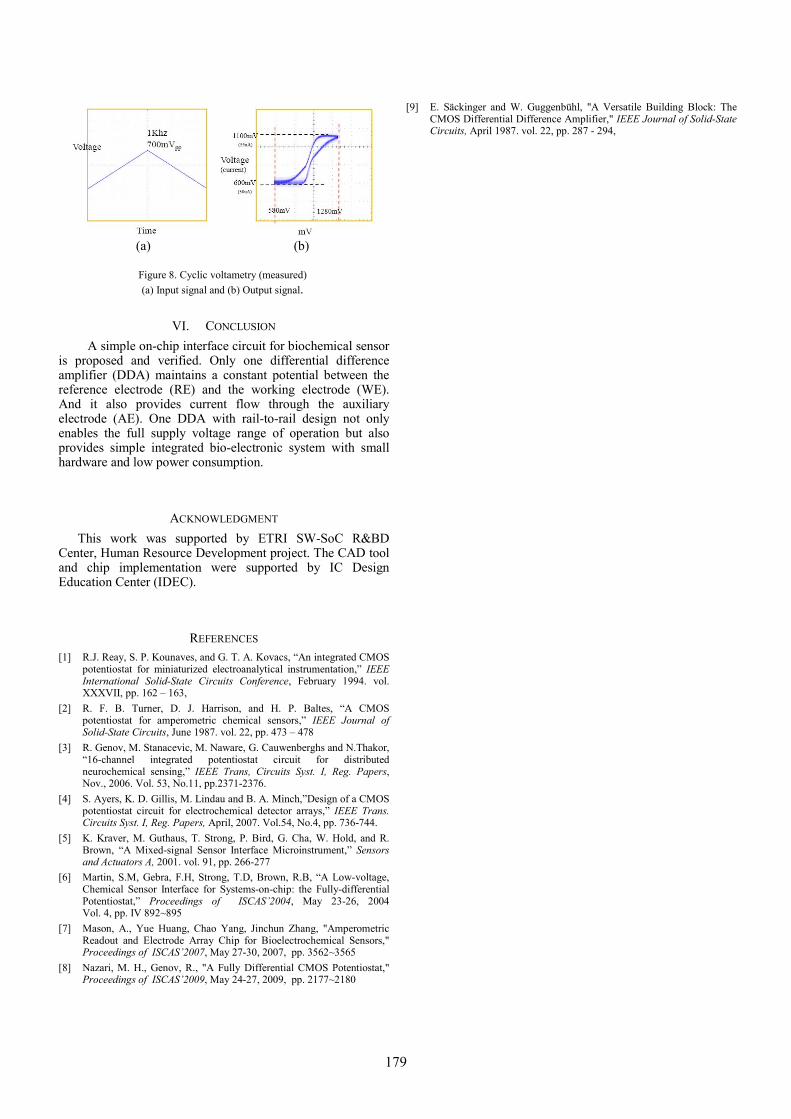
V. MEASUREMENT Fig. 7 shows the cell (solution) kit and biochemical sensor
chip for evaluation. In order to characterize the performance of the proposed biochemical sensor interface chip, electrochemical cell with three-electrode (the auxiliary electrode: AE, the reference electrode: RE, and the working electrode: WE) was connected to this implemented sensor interface chip. The triangular waveform as shown in Fig. 8 (a) is applied to the cell solution of 1 Mol ammonium sulfate [(NH4)2SO4] through the graphite electrodes to confirm cyclic voltametry operation. The data was captured at the output of TIA using a Tektronix MSO4104 mixed signal oscilloscope. Fig. 8 (b) clearly shows the measured result of oxidation peak and reduction peak in cyclic voltametry.
Technology M/H 0.35um CMOS
Operation Voltage 3.3V
Power Consumption 532uW
Core size 300um x 445um(without pads)
DDA gain 135dB
DDA Phase Margin 65˚
DDA CMRR 170dB
TIA gain 125dB
Figure 4. Simulation results of DC sweep
Figure 7. Test set up for evaluation
Figure 6. Layout of proposed circuits
Figure 5. Transient simulation results
178
VI. CONCLUSION
A simple on-chip interface circuit for biochemical sensor is proposed and verified. Only one differential difference amplifier (DDA) maintains a constant potential between the reference electrode (RE) and the working electrode (WE). And it also provides current flow through the auxiliary electrode (AE). One DDA with rail-to-rail design not only enables the full supply voltage range of operation but also provides simple integrated bio-electronic system with small hardware and low power consumption.
ACKNOWLEDGMENT This work was supported by ETRI SW-SoC R&BD
Center, Human Resource Development project. The CAD tool and chip implementation were supported by IC Design Education Center (IDEC).
REFERENCES [1] R.J. Reay, S. P. Kounaves, and G. T. A. Kovacs, “An integrated CMOS
potentiostat for miniaturized electroanalytical instrumentation,” IEEE International Solid-State Circuits Conference, February 1994. vol. XXXVII, pp. 162 – 163,
[2] R. F. B. Turner, D. J. Harrison, and H. P. Baltes, “A CMOS potentiostat for amperometric chemical sensors,” IEEE Journal of Solid-State Circuits, June 1987. vol. 22, pp. 473 – 478
[3] R. Genov, M. Stanacevic, M. Naware, G. Cauwenberghs and N.Thakor, “16-channel integrated potentiostat circuit for distributed neurochemical sensing,” IEEE Trans, Circuits Syst. I, Reg. Papers, Nov., 2006. Vol. 53, No.11, pp.2371-2376.
[4] S. Ayers, K. D. Gillis, M. Lindau and B. A. Minch,”Design of a CMOS potentiostat circuit for electrochemical detector arrays,” IEEE Trans. Circuits Syst. I, Reg. Papers, April, 2007. Vol.54, No.4, pp. 736-744.
[5] K. Kraver, M. Guthaus, T. Strong, P. Bird, G. Cha, W. Hold, and R. Brown, “A Mixed-signal Sensor Interface Microinstrument,” Sensors and Actuators A, 2001. vol. 91, pp. 266-277
[6] Martin, S.M, Gebra, F.H, Strong, T.D, Brown, R.B, “A Low-voltage, Chemical Sensor Interface for Systems-on-chip: the Fully-differential Potentiostat,” Proceedings of ISCAS’2004, May 23-26, 2004 Vol. 4, pp. IV 892~895
[7] Mason, A., Yue Huang, Chao Yang, Jinchun Zhang, "Amperometric Readout and Electrode Array Chip for Bioelectrochemical Sensors," Proceedings of ISCAS’2007, May 27-30, 2007, pp. 3562~3565
[8] Nazari, M. H., Genov, R., "A Fully Differential CMOS Potentiostat," Proceedings of ISCAS’2009, May 24-27, 2009, pp. 2177~2180
[9] E. Säckinger and W. Guggenbühl, "A Versatile Building Block: The CMOS Differential Difference Amplifier," IEEE Journal of Solid-State Circuits, April 1987. vol. 22, pp. 287 - 294,
(a) (b)
Figure 8. Cyclic voltametry (measured) (a) Input signal and (b) Output signal.
179