Bimodal Cavities for RF Breakdown Studies · 300 12.57 2.403 15.301 TM 010 TM 020 RF power...
22
Bimodal Cavities for RF Breakdown Studies Research supported in part by US DoE –Office of High Energy Physics Y. Jiang, 1 S.V. Kuzikov, 2,3 and J. L. Hirshfield 1,2 1 Beam Physics Laboratory, Yale University, New Haven, CT 06511, USA 2 Omega-P, Inc., 258 Bradley St., New Haven, CT 06510, USA 3 Institute of Applied Physics, Nizhny Novgorod, Russia
Transcript of Bimodal Cavities for RF Breakdown Studies · 300 12.57 2.403 15.301 TM 010 TM 020 RF power...

Bimodal Cavities for RF Breakdown Studies
Research supported in part by US DoE –Office of High Energy Physics
Y. Jiang,1 S.V. Kuzikov,2,3 and J. L. Hirshfield1,2
1Beam Physics Laboratory, Yale University, New Haven, CT 06511, USA2Omega-P, Inc., 258 Bradley St., New Haven, CT 06510, USA
3Institute of Applied Physics, Nizhny Novgorod, Russia

Contents
References:
• “Asymmetric bimodal accelerator cavity for raising RF breakdown thresholds,” by S.V. Kuzikov, S.Yu. Kazakov, Y. Jiang, and J.L. Hirshfield, Phys. Rev. Lett. 104, 214801 (2010).
• “High-gradient two-beam accelerator structure,” by S.Yu. Kazakov, S.V. Kuzikov, Y. Jiang, and J.L. Hirshfield, submitted to Phys. Rev. ST – Accel. & Beams (2010).
• Motivation
• Multi-Harmonic Cavity Example
• Bimodal Test Cavity
• Dual Frequency Test Facility
• Multi-Harmonic Accelerator Structure

Multi-Harmonic Cavities to Increase Breakdown Threshold
• shorten the exposure times on metallic cavitysurfaces to the peak RF electric fields during eachRF cycle;
• yield RF electric fields that point into metalliccavity surfaces to be always smaller than fieldsthat point away from the surfaces; and
• cause the exposed areas on the cavity surfacewhere RF magnetic fields have peak values toshrink and sweep around the surface during eachRF cycle.
Superimposing harmonically-related modes
• Initiated by electron emission driven bythe RF electric field directing towards thewall, where electrons can be accelerated toescape from the wall, and stimulate abreakdown event;
• Promoted at surface irregularities whichare accentuated by stresses induced bypulsed heating due to surface RF magneticfields.
Hypotheses of the onset of RF breakdown
These interconnected mechanisms may occur together
Eigenmodes TM010 TM020 TM030
Freq (GHz) 2.99998 5.99995 8.99993
Q (Cu walls) 7041.63 10789.1 14077.5
Tri-modal cavity supports three modes at harmonically-related frequencies. Cavity fields are symmetric around the cavity axis, but asymmetric along the axis.
Example of Multi-Harmonic Mode Cavity (3 Modes)

Peak electric field envelope around the cavityperiphery as coordinate s advances along thecavity perimeter and along the cavity axis. Redsegments are anodelike, while blue segments arecathodelike. Magenta segments are fields alongthe cavity axis.
Anode-Cathode Effect in Multi-Harmonic Cavity
Ec is peak magnitude of electric field pointingtowards a cavity surface (cathodelike), and Gis the acceleration gradient. For the cavityprofile shown, R = 1.55 with field amplituderatio E1:E2=1 : 0.4.
Thus, a structure using such multimodecavities might support an accelerationgradient about 55% greater than that for astructure using similar single-mode cavities,without an increase in breakdownprobability.
multi-mode
PillboxCavity
/
/
c
c
G ER
G E
b
Za c
de
S
We define a “benefit ratio” R, as
cavity profile
Anode
Anode
Cathode
Cathode
axisPeak
Ele
ctri
c Fi
eld
periphery distance s (mm)
a b c d e

b
a
c
dS
a b c d
periphery distance s (mm)H
2(A
rb. U
nit
)
Magnetic field pattern
3 GHz 6 GHz
RF Pulse Heating in Multi-Harmonic Cavity
It has been estimated by the coauthor S. Kuzikov that the total temperature risefrom two mode excitation in similar multi-harmonic cavities driven by CTF3 beamis ~50 C. Such temperature level suggests that the multi-harmonic cavity issuitable to accumulate necessary statistical information about breakdown rate.
Temperature rise ΔT proportional to H2

(a) Development of bimodal asymmetric demountable cavities to incorporate practical couplers and diagnostics;
(b) Implementation of low-power cavities for cold tests to confirm the designs; and
(c) Preparation of a dual-frequency multi-MW mutually-phase coherent RF source for high-power dual-frequency tests to follow.
RF Breakdown Experiment using Bimodal Cavity
Experimental efforts are being carried out with

Frequency (GHz) 2.85599 5.71196
Q 8229.97 12856.8
R (M Ω/m) 41.30 48.26
R/Q (Ω/m) 5018.34 3753.43
Pw(MW) @100MV/m Esurface 3.492 1.976
Bimodal Asymmetric Cavity
TM010 TM020
Electric Field Map
Magnetic Field MapEsurface
(MV/m)P1 (MW) P2(MW) Ptotal (MW)
100 1.397 0.267 1.700
200 5.587 1.068 6.800
300 12.57 2.403 15.301
TM010 TM020
RF power requirements for 2.856 GHz and 5.712 GHzcoherent sources needed to sustain the listed peaksurface fields with E2 = 0.5812E1, assuming thatbreakdown would not intervene.

A coupling design is used to couple power from two phase-locked high-power RF sources into the bimodal cavity. Amplitude and phase of RF can be adjusted to study various scenarios with certain effect dominant.
Coupling Design for Bimodal Cavity
Courtesy of S. Kazakov

A bimodal asymmetric cavity design in a clamped structure with demountable bottom flat surface allows convenient replacement of test plates for inspection and reassembling without disconnecting or changing the dual-frequency RF coupling and power feeding systems.
• The bottom surface is expected to exhibit the greatest damage from breakdown, due to the anode-cathode field imbalance.
• The two input waveguides and the top portion of the cavity are to be reused for a series of tests with varying power levels and phases for the two RF sources, to gauge the validity of the anode-cathode imbalance conjecture.
Conceptual Design of Demountable Bimodal Cavity

Drawing of the test cavity with a flexible wall:
1 – cavity body; 2 – simulated beam tunnel; 3 –
tuning screw, 4 – coupling holes; 5 – waveguide
flanges.Courtesy of S. Kuzikov
Cold Test of Tunable Bimodal Cavity
Bimodal symmetric cavity wasbuilt with its TM010-like modewith f1 = 7.0 GHz and TM020-like mode with f2 = 14.0 GHz,with greater sensitivity tofabrication errors.
Tuning of frequencies wasachieved by slightly squeezing2-mm thick flexible copper wallwhich could be easily deformedby ~1 mm without plasticdeformation. The first mode ismore sensitive to such walldisplacement than is thesecond.

Measured transmission vs frequency: (a) before cavity deformation, (b) after cavity deformation.Red curve corresponds to 14 GHz mode, blue curve corresponds to 7 GHz mode, whose transmissionis plotted as function of 2×f.
The difference between the doubled frequency of the first mode and thefrequency of the second mode, i.e., Δf = 2f1 – f2, characterizes a measure of modeharmonicity.
Initial mode equidistance exceeded 26 MHz. Δf ~ 1 MHz can be achieved bysqueezing the wall to shift by approximately 0.1 mm.
Tuning of Bimodal Cavity
(a) (b)

Dual-Frequency Test Facility
Layout of dual-frequency RF source, shown
feeding a bimodal test cavity.
1 – S-band klystron; 2 – variable power splitter; 3
– 3-dB hybrid splitter; 4 – 250-kV gun tank; 5 –
variable power splitter and phase shifter; 6 - bimodal
test cavity.
This dual-frequency source isbased on an XK-5 24-MW S-bandklystron, an S-band waveguidetransmission line with provisionfor power splitting into twoportions with adjustableamplitude and phase, and asecond-harmonic frequencymultiplier to produce the C-bandpower.
Thus, the two sources would beautomatically phase-locked, andno new modulator or C-banddriver would be needed.

input power at 2856 MHz 6.0 MWoutput power at 5712 MHz ~5.3 MW
RF-to-RF conversion efficiency ~88 %operating mode in drive cavity TE111
maximum surface field in drive cavity 46 kV/cmloaded Q of drive cavity 150
operating mode in output cavity TE211
maximum surface field in output cavity 113 kV/cmloaded Q of output cavity 400
output cavity length and diameter 60 mm, 55.7 mm
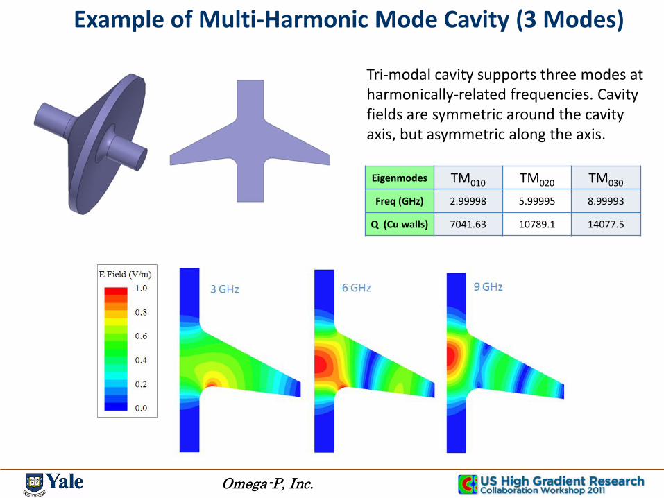
Second-Harmonic Frequency Multiplier
The 2nd harmonic source uses the250 kV, 20 A gun, modulator,magnetic system, and beamcollector. 6 MW Power from theklystron is going to the input toyield 5.712 GHz output power ofabout 5.3 MW.

Cavities for Second-Harmonic Frequency Multiplier
The frequency multiplier is built with a demountable output cavity, to allowsubstitution of different output cavities to operate at different harmonics.
Drive Cavity for Second-Harmonic Frequency Multiplier

Output Cavity for Second-Harmonic Frequency Multiplier

Computations of beam particle energies (blue) andorbit radii (red) for the 5.7 GHz 2nd harmonic frequencymultiplier. Cavity and pole piece outlines are shown.
Magnetic field profile in the 5.7 GHz, 2nd harmonicfrequency multiplier. Shown at bottom are the coilsystem and iron circuit, plus the cavity outlines.
Computational Predictions for Second-Harmonic Frequency Multiplier
The 2nd harmonic frequency multiplier is to be built using a TE111 rotating mode input cavity with a TE211 rotating mode output cavity.

Multi-Harmonic Cavity Acceleration Structure with Helical Waveguide
Usual way of feeding rf through the cavity beam channel may not work for multi-frequencies as they will have different dispersion property.
Double helical waveguide structure isintroduced to couple individualcavities with correct synchronizationfor each frequency:
Fast wave in waveguide propagateslonger helical path to match the phase ofthe test beam passing the cavity axis.
* Simplified model: uniform coupling without choke

Multi-Harmonic Excitation and Synchronization via Double Helical Waveguide
Bunch frequency: 3 GHzPhase advance in waveguide: 2π/3Phase advance of particle: 2π/3
External rf: 3 GHz
Test beam

External rf: 6 GHz
test beam
Bunch frequency: 3 GHzPhase advance of particle: 2π/3Phase advance in waveguide: 4π/3 @ 6 GHz
Multi-Harmonic Excitation and Synchronization via Double Helical Waveguide

Summary
• Use of bimodal cavities may allow an increase in RF breakdown threshold, due to:
a. Reduced exposure times to high fields;b. Cathode-like fields being weaker than anode-like fields;c. Migration of field patterns around cavity periphery.
• A two-frequency synchronous multi-MW RF source and a demountable test cavity are being built at Yale for breakdown studies of bimodal cavities, at 2.85 and 5.7 GHz.
• When/if bimodal cavities are proven to allow an increase in RF breakdown thresholds, inventive coupling schemes will be needed; a double-helix scheme has been illustrated.