
Dr. Feras Fraige Faculty of Applied Engineering King Saud ...
Upload
arnold-watsonCategory
view
218download
0
BIM and Preconstruction
King Saud UniversityEngineering College
Civil Engineering Department
-CE 613-
Presented by Dr. Khalid Al-Ghtani

BIM and Construction Management
Outline
Conclusion
Site Coordination
Estimating
Digital Information Transfer Standards
Defining Responsibilities and Ownership
Contracts
Planning a BIM Project

Planning a BIM Project
A good construction manager knows that any successful project begins with good planning (see Figure 2-1). This is true for planning a BIM project.
Figure 2-2: The construction of the Pantheon in Rome required precision, the right tools, and years of experience.
Planning a BIM Project
The following are critical factors in planning a BIM project:
Educate the team Educate team members on the reasons BIM technology is being used.
Achieve team buy-in All the members of the team should realize the importance of their role in the process
Set goals This is a good way of quantifying successes in a scalable manner.
Take it a step at a time Identify which technologies your group will be using on a project at what time in a project.
Contracts
The intention of a contract, especially when geared toward BIM users, is not to point fingers if something goes wrong but rather to clearly define tasks, responsibilities, and rights at the onset of a project.
Contracts on a BIM project determine a contractor’s ability to influence and collect and share data throughout the project’s life cycle.

Contracts
A number of groups have model contracts geared toward integrated projects and language you can use to develop contracts such as:
American Institute of Architects (AIA),Associated General Contractors of America (AGC),Design-Build Institute of America (DBIA)

Defining Responsibilities and Ownership
In all the types of contracts discussed, the project team members need to define how data will be shared and used (see Figure 2-5) in order to do the following:Eliminate confusionOrganize tasksStandardize information
transferDefine the scheduleFocus on project quality Figure 2-5: BIM has multiple uses and stakeholders, so
defining the rights and responsibilities are critical between team members and model users.

Defining Responsibilities and Ownership
Although the answer to the model sharing solution does not have a standard answer, it does offer flexibility for the team and positions the responsibilities of a project to be most effective (see Figure 2-7).

Information Exchange (IE) Plan
Architect’s IE Responsibilities:Responsible for communicating the design intent of the structure
through documentation to the team. Responsible for coordinating information regarding life safety,
code compliance, and accessibility issues.Responsible for issuing BIM information and documentation.Responsible for tracking the date, time, and people.Responsible for model coordination and model ownership through
the design phase and 100 percent construction documentation milestone of the project
The following is a preliminary draft of the IE plan for different members of the project team:

Information Exchange (IE) Plan
Contractor’s IE Responsibilities:Responsible for reviewing the architect’s design intent modelResponsible for maintaining and layering information onto the
singular modelResponsible for creating and maintaining sequencing animationResponsible for clash detection reportingResponsible for creating the as-built or record BIM
The following is a preliminary draft of the IE plan for different members of the project team:

Information Exchange (IE) Plan
Mechanical, Electrical, Plumbing, and Structural Engineers’ IE Responsibilities:Responsible for the 3D creation of the systemsResponsible for accurately updating the project team on model
changesResponsible for making recommendations to the design team on
performanceResponsible for making alterations to the design model after a
clash has been reportedResponsible for submitting the completed clash report
The following is a preliminary draft of the IE plan for different members of the project team:
Digital Information Transfer Standards
There are two schools of thought on using BIM:
Creating a parallel BIM model for use by individual professionalsUsing a composite BIM model for all disciplines

Digital Information Transfer Standards
Parallel BIM:The idea of parallel BIM model is to create a separate model for
use by contractors based on the information provided by the architects and engineers.
Although this helps ensure that the model will be useful and specific to the contractor’s needs, there is a liability that the model may not be an exact reflection of the architect’s and engineers’ models; there may also be a conflict with the architect’s and engineers’ contractual responsibility for communicating the design intent for theproject.

Digital Information Transfer Standards
Single BIM
The second method of BIM is maintaining a composite BIM model.
Although this method requires an advanced understanding of BIM software programs and relationships, it is truly where BIM shines.
Understand that singular modeling is not necessarily everyone working on the same model at the same time; instead, it lets users work on their own models and link or import the models together to create a “composite” model.

Estimating
Extracting quantities, areas, and volumes from a model is one of the most useful functions BIM technology offers.
The following tutorial uses a Revit model and shows how to use Innovaya’s estimating tool to extract quantities from the model and then tie them to a Timberline estimate.
Other software combinations are also available, such as Vico Software and Beck Technology’s DProfiler, with which you can accomplish similar tasks.

Revit
Autodesk Revit is a BIM software modeling program that allows you to design with parametric modeling and drafting elements.
In other words, the model is interconnected; a change in one place propagates changes throughout the model. For instance, if a wall is moved 3 feet in plan, that wall now moves in elevation, section, perspective, and all other relative views.
Revit is not the only BIM software available. ArchiCAD, Bentley, and VectorWorks, among others, all offer BIM modeling packages, which all accomplish approximately the same tasks.
Revit
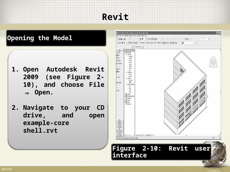
1. Open Autodesk Revit 2009 (see Figure 2-10), and choose File Open.⇒
2. Navigate to your CD drive, and open example-core shell.rvt
Opening the Model
Figure 2-10: Revit user interface

Revit
3. Once Revit has loaded the file, click the View tab, and specify 3D view or click the 3Dbutton at the top of the Revit toolbar (see Figure 2-11).
Opening the Model
Figure 2-11: Revit 3D view control

Revit
Opening the Model
4. With the 3D view open, you can move around and position the model for viewing and for enhanced understanding of the model, giving you a better understanding of the scope of the model and showing you any potentially incomplete components around the structure.
5. Click View Visibility/Graphics to isolate components. ⇒Alternatively, type VG.Once you have explored the sample structure enough to have a basic understanding about what is being estimated, you can export the model into an Innovaya (INV) file.

Revit
Innovaya Composer
Innovaya Composer (www.innovaya.com) is a model-linking Revit plug-in tool that converts an RVT file to an INV file.
In essence, it converts all the BIM components into a file format that is easy to view as estimate-related data and quantity information.
Innovaya Composer creates a link in the chain from Revit through Innovaya to Timberline.

Revit
Innovaya Composer
In Revit, choose Tools ⇒External Tools ⇒Innovaya Composer for Revit (see Figure 2-12).
Figure 2-12: Exporting to Innovaya
Revit
Innovaya Composer
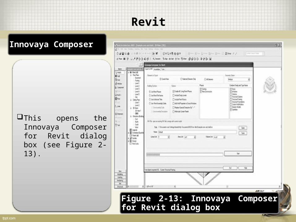
This opens the Innovaya Composer for Revit dialog box (see Figure 2-13).
Figure 2-13: Innovaya Composer for Revit dialog box

Revit
Innovaya Composer
Exporting an Innovaya File
1. Click Start at the bottom right of the Composer window.
2. 2. Specify where you want to save the file.
3. 3. Click Save. You should see a message that your export was successful (see Figure 2-14).
Figure 2-14: Successful export message
Innovaya
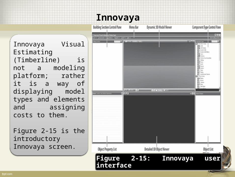
Innovaya Visual Estimating (Timberline) is not a modeling platform; rather it is a way of displaying model types and elements and assigning costs to them.
Figure 2-15 is the introductory Innovaya screen.
Figure 2-15: Innovaya user interface

Innovaya
1. Launch Innovaya Visual Estimating (Timberline).
2. Click Start Open ⇒Project, as shown in Figure 2-16. Innovaya should default to the location you last exported a file to. If not, specify the file you exported.
Figure 2-16: Opening a project in Innovaya
Exploring the Innovaya Interface

Innovaya
1. Launch Innovaya Visual Estimating (Timberline).
2. Click Start Open ⇒Project, as shown in Figure 2-16.
3. Maximize the New Construction window at the top left.
Figure 2-16: Opening a project in Innovaya
Exploring the Innovaya Interface

Innovaya
1. Select Quantities Batch Generate ⇒
(see Figure 2-18).
2. Use the default settings, and export all the items in the model.
Figure 2-18: Using the Batch Generate function
Generating Managed Quantities

Innovaya
3. Select Quantities ⇒Export to Excel (see Figure 2-20) to quickly export an estimate of items in the BIM to Microsoft Excel.
Figure 2-20: Exporting to Excel from Innovaya
Generating Managed Quantities

Innovaya
4. In the Export Excel dialog box, specify the number of digits after the decimal. This opens an Excel workbook (see Figure 2-21) that shows you square footage, width, height, level association, assembly codes, counts, and so forth.
Figure 2-21: Exported Innovaya BIM takeoff in Excel
Generating Managed Quantities

Timberline
Next, link your model to a Timberline estimate, which is linked to a database.
Timberline estimating, from Sage Software, is a large database geared specifically toward estimators.
The basic functionality of Timberline is to enable users to automate their estimating processes.
Timberline
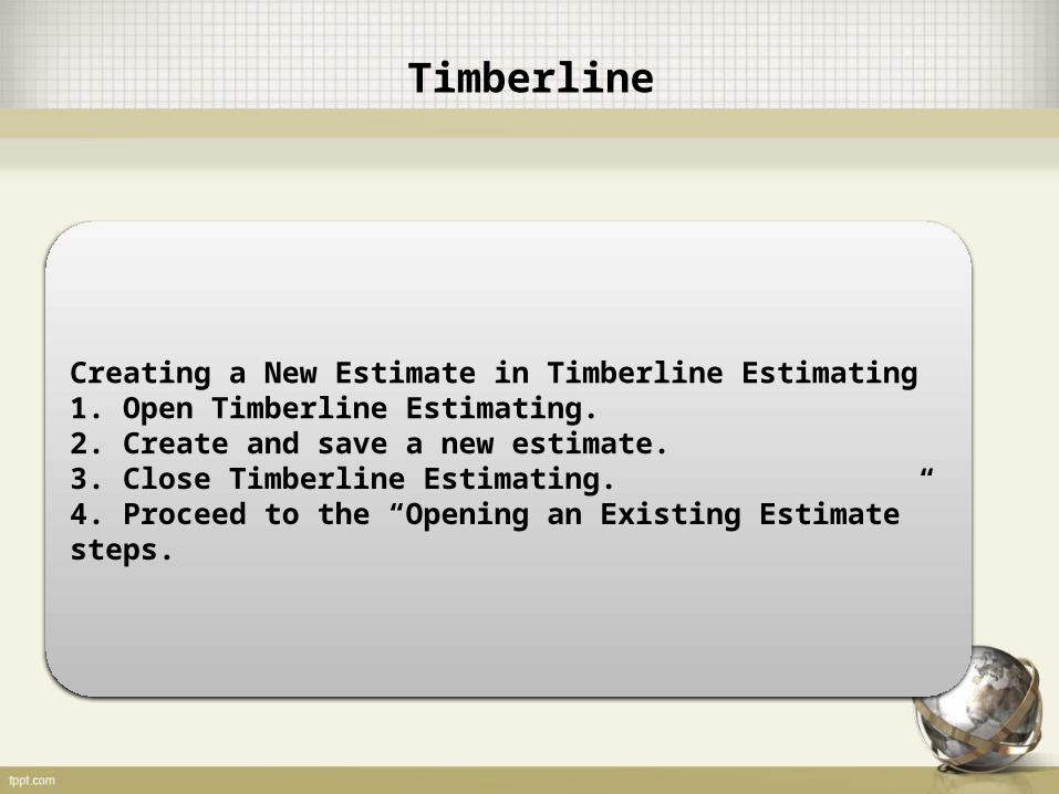
Creating a New Estimate in Timberline Estimating1. Open Timberline Estimating.2. Create and save a new estimate.3. Close Timberline Estimating.4. Proceed to the “Opening an Existing Estimate” steps.
Timberline
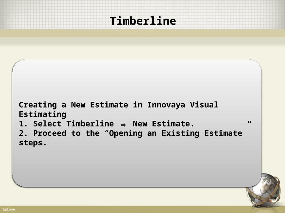
Creating a New Estimate in Innovaya Visual Estimating1. Select Timberline New Estimate.⇒2. Proceed to the “Opening an Existing Estimate” steps.

Timberline
1. Click Sort by Component Types in the Managed Quantities pane, as shown in Figure 2-23.
2. Expand the Level 1 listing and then the Walls category.3. Click the first wall listed, 12² Concrete Foundation Wall.
Figure 2-23: Using Sort by Component Type to identify a BIM element
Assigning Costs
Timberline
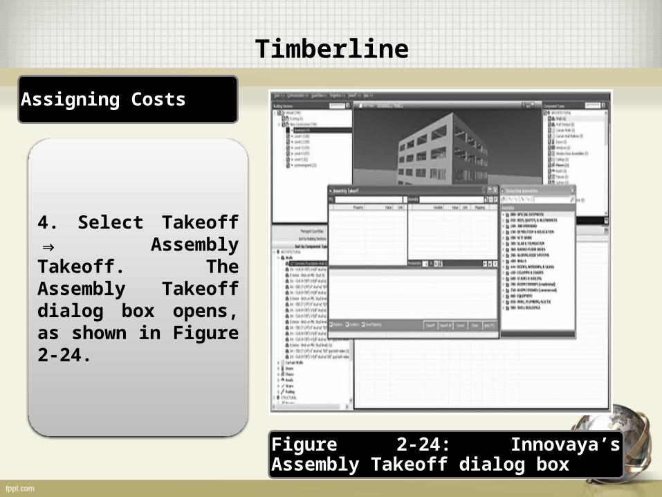
4. Select Takeoff ⇒Assembly Takeoff. The Assembly Takeoff dialog box opens, as shown in Figure 2-24.
Figure 2-24: Innovaya’s Assembly Takeoff dialog box
Assigning Costs

Timberline
5. Now drag and drop the 12˝ Concrete Foundation Wall item from the Managed Quantities pane to the MQ field at the upper left of the Assembly Takeoff dialog box (see Figure 2-25).
Figure 2-25: Dragging and dropping quantities into the Assembly Takeoff dialog box
Assigning Costs

Timberline
6. In the Timberline Assemblies window, assign a cost link to the 12˝ Concrete Foundation Wall by clicking the 400 Walls category to expand it and then dragging and dropping the Concrete Wall category on top of the blank Assembly pane (see Figure 2-26).
Figure 2-26: Dragging and dropping Timberline assemblies to the Assembly Takeoff dialog box
Assigning Costs

Timberline
7. Drag and drop the length and height from the MQ pane onto the corresponding variables in the Assembly pane to create a takeoff (see Figure 2-27).
Figure 2-27: Assembly pane after takeoff
Assigning Costs

Timberline
8. At the lower right of the Assembly pane is the Pass box; it’s the one with a green check mark in it with 0 showing to its right.
9. Ensure that the Replace check box at the lower left of the Assembly pane is selected.
10. Click the Takeoff button at the bottom of the Assembly Takeoff dialog box to add the wall to the estimate.
The concrete wall has now been added to the Timberline estimate and should be visible in the Estimate pane (see Figure 2-28).
Repeat the previous steps for the Int-S1A (4 7⁄8˝) wall, using the 436-Metal Framed Wall Interior Timberline assembly. Add a pass, and then click the Takeoff button (see Figure 2-29).
Assigning Costs

Timberline
Figure 2-28: Wall added to estimate
Figure 2-29: Using the Takeoff tool

Timberline
1. Select Takeoff Auto-⇒Takeoff (see Figure 2-30).
2. Accept the default settings in the Auto-Takeoff window, and click the Go button.
3. Continue assigning costs and mapping components to the estimate for the walls, roofs, and floors.
Figure 2-30: Auto-Takeoff on the Takeoff menu
Using the Auto-Takeoff Function

Site Coordination
Google SketchUp (http://sketchup.google.com) is a free, intuitive program that is useful during the schematic and conceptual phase of projects for designers who want to understand the tectonics, scale, and massing of a design.
Starting the Site Coordination Plan in SketchUp

Site Coordination
1. Start Revit Architecture.
2. Navigate to your CD drive, and open example-core-shell.rvt
3. Switch to 3D view in the Project Browser.
4. Select File Export ⇒ ⇒CAD Formats (see Figure 2-33). The Export CAD dialog box opens.
Figure 2-33: Exporting from Revit to a CAD format for use in SketchUp
Exporting from Revit to SketchUp

Site Coordination
5. Specify the type of file you want to export your 3D model as. Choose AutoCAD.
6. In the Export CAD Formats dialog box, click Options.
7. Select ACIS Solids as the export type.
8. Click Save to export the file and keep the file nomenclature the same.
Exporting from Revit to SketchUp

Site Coordination
1. Launch Google SketchUp.2. In SketchUp, select File Import.⇒3. In the Files of Type field, choose ACAD files (*.dwg, .*dxf).4. Navigate to the CAD file you just exported, and, using the default settings, click Open.5. After the model loads, click the selection tool (the arrow at the upper left of the SketchUp interface), and click the model. It should highlight in blue.6. Right-click, and choose Explode (see Figure 2-34). This breaks the model into its original components.
Importing into SketchUp and Exploding the Model

Site Coordination
Importing into SketchUp and Exploding the Model
Figure 2-34: Exploding the model in SketchUp

Site Coordination
1. Click the Materials toolbar to expand it.
2. You can now begin painting the model by clicking a material in the toolbar and then clicking the model component you want to assign it to (see Figure 2-35).
Figure 2-35: Applying materials in SketchUp
Painting the Model in SketchUp

Inserting the Site
1. Enter an address in the Search field.2. Zoom into the area you want to use as the site,3. Toggle back over to Google SketchUp without closing
Google Earth.4. In SketchUp, move to the top or plan view.5. Click the Get Current View button; this is the world icon with a yellow arrow over the top of it (see Figure 2-38).6. Place the model on the site by moving the model on top of the site image and positioning it. After your building is positioned, it should look like Figure 2-39.7. Click the Toggle Terrain button (see Figure 2-40) to view the slope of the terrain.
Importing a Site with Google Earth

Inserting the Site
Importing a Site with Google Earth
Figure 2-38: Get Current View button in SketchUp
Figure 2-39: Google Earth terrain placed in SketchUp

Inserting the Site
Importing a Site with Google Earth
Figure 2-40: Toggle the view between a flat photo of site and a 3D representation of terrain with the Toggle Terrain button.

Inserting the Site
Click the Place Model button in SketchUp (see Figure 2-43).
This inserts the SketchUp site coordination plan into Google Earth temporarily (see Figure 2-44) so you can use it to analyze a particular site.
Exporting a Site Coordination Plan to Google Earth

Site Coordination
Figure 2-43: Clicking the Place Model button exports the SketchUp site coordination plan to Google Earth.
Exporting a Site Coordination Plan to Google Earth
Figure 2-44: A model placed into Google Earth, showing a 3D view

Conclusion
Using BIM and BIM-aware tools can give you an early understanding of what the scale, site, and building conditions are and what the cost of a project is.
Using BIM, and the technologies that support its varied uses, helps inform the project team and streamline processes.
As a design model changes throughout the course of a project, you can use the BIM as a tool to coordinate takeoff and costs.