Bigelow Expandable Activity Module (BEAM) ISS … · Bigelow Expandable Activity Module ... (April...
37
Bigelow Expandable Activity Module (BEAM) ISS Year-One Gerard Valle & Nathan Wells BEAM Project Management and Instrumentation Team ISS R&D Conference, Washington DC 19-July-2017 1 https://ntrs.nasa.gov/search.jsp?R=20170006506 2018-08-20T05:23:27+00:00Z
Transcript of Bigelow Expandable Activity Module (BEAM) ISS … · Bigelow Expandable Activity Module ... (April...
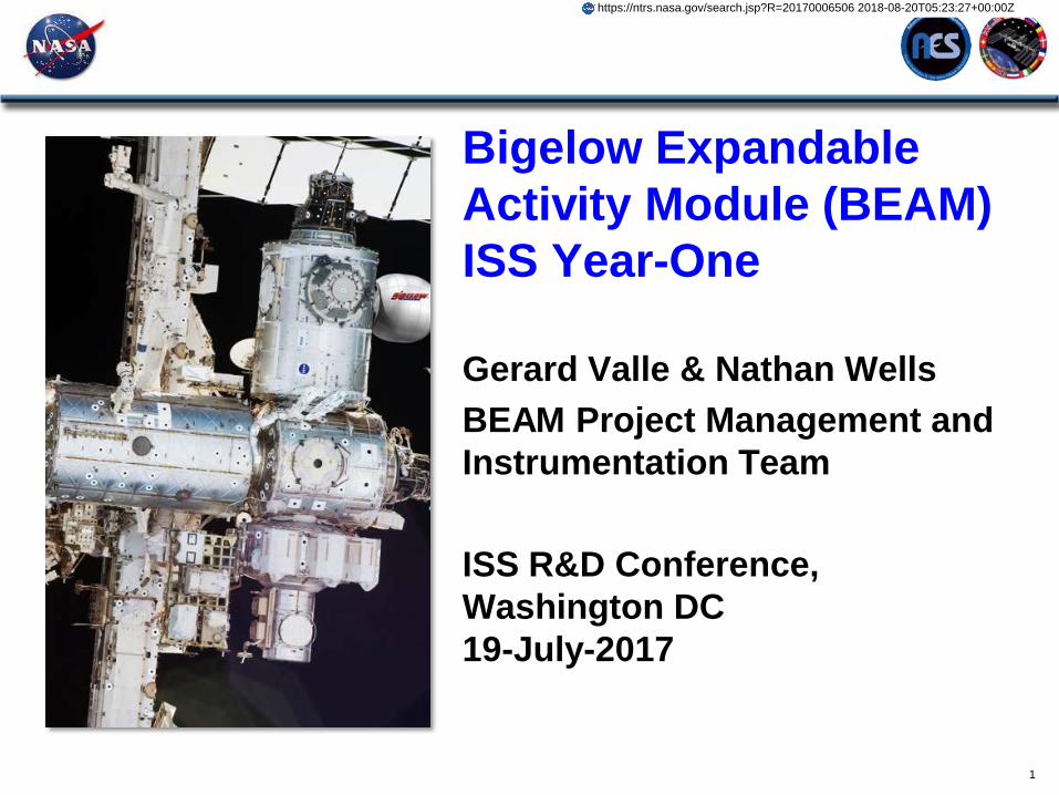
Bigelow Expandable
Activity Module (BEAM)
ISS Year-One
Gerard Valle & Nathan Wells
BEAM Project Management and
Instrumentation Team
ISS R&D Conference,
Washington DC
19-July-2017
1
https://ntrs.nasa.gov/search.jsp?R=20170006506 2018-08-20T05:23:27+00:00Z
BEAM Project
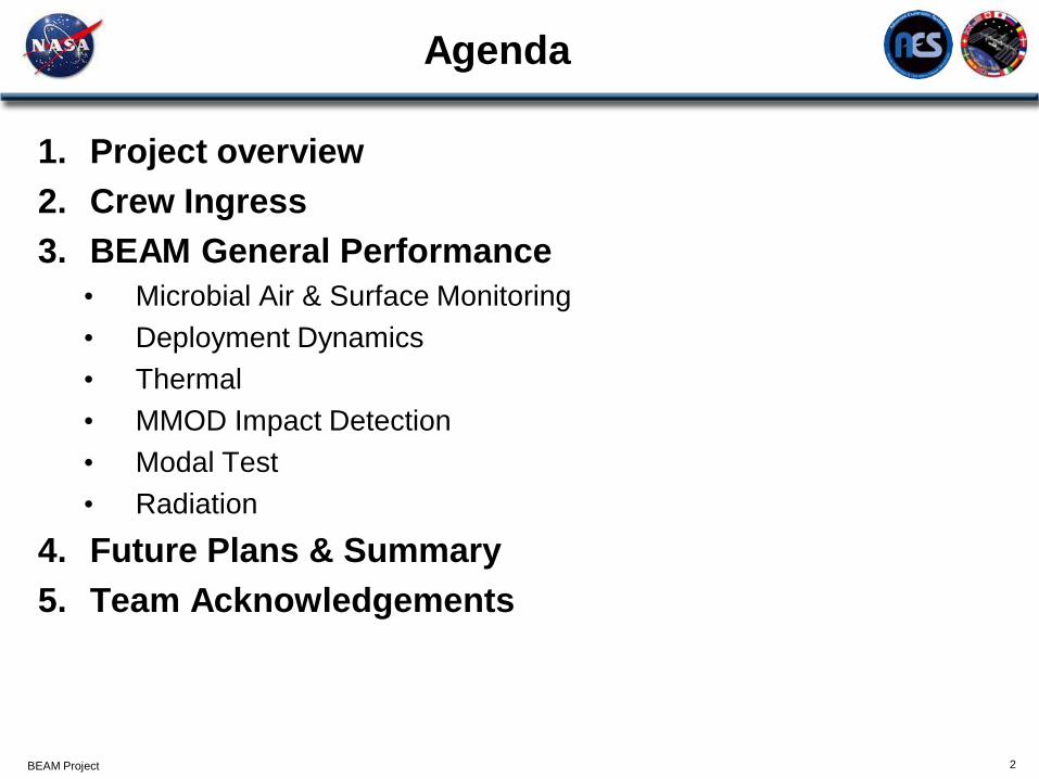
Agenda
1. Project overview
2. Crew Ingress
3. BEAM General Performance
• Microbial Air & Surface Monitoring
• Deployment Dynamics
• Thermal
• MMOD Impact Detection
• Modal Test
• Radiation
4. Future Plans & Summary
5. Team Acknowledgements
2

BEAM Project
BEAM project objectives
3
BEAM on ISS Node 3 Aft
Demonstrate a commercial expandable habitat module on ISS in partnership with Bigelow
Aerospace (BA)
Increase human-rated inflatable structure Technology Readiness Level (TRL) to 9
Address key elements of NASA’s Space Technology Roadmaps to prepare for future deep
space and surface habitat missions
Exploit experience from NASA’s TransHab design and BA’s Genesis I & II pathfinder flights
BEAM animation by NASA/JSC on YouTube
https://youtu.be/VopaBsuwikk
BEAM Project
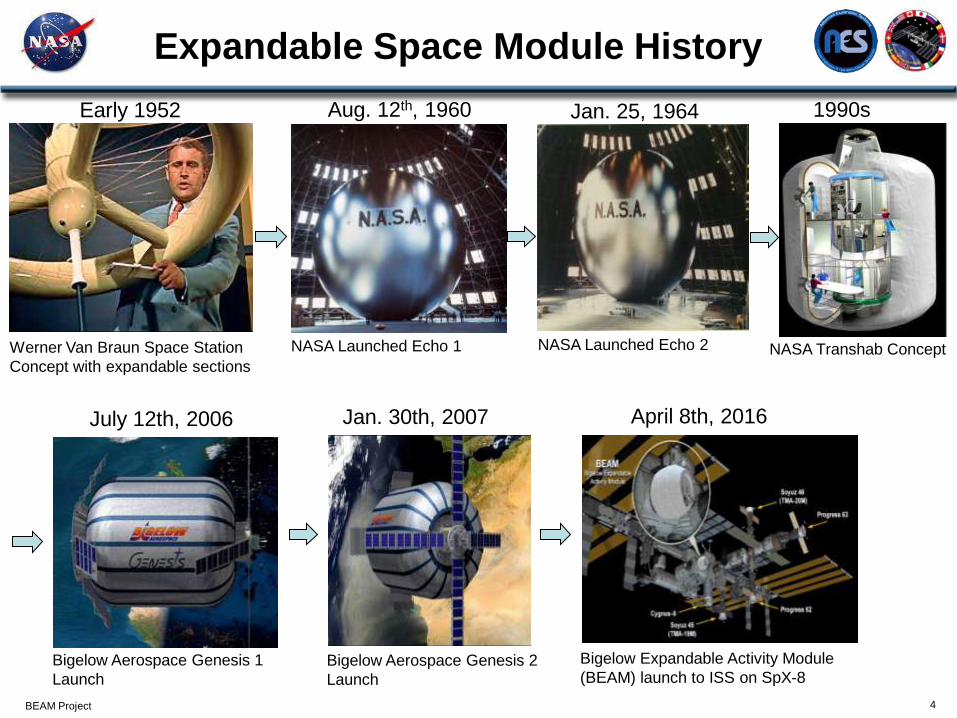
Expandable Space Module History
4
NASA Launched Echo 1 Werner Van Braun Space Station
Concept with expandable sections
NASA Launched Echo 2 NASA Transhab Concept
Early 1952 Aug. 12th, 1960 Jan. 25, 1964 1990s
July 12th, 2006 Jan. 30th, 2007
Bigelow Aerospace Genesis 1
Launch
Bigelow Aerospace Genesis 2
Launch
April 8th, 2016
Bigelow Expandable Activity Module
(BEAM) launch to ISS on SpX-8
BEAM Project
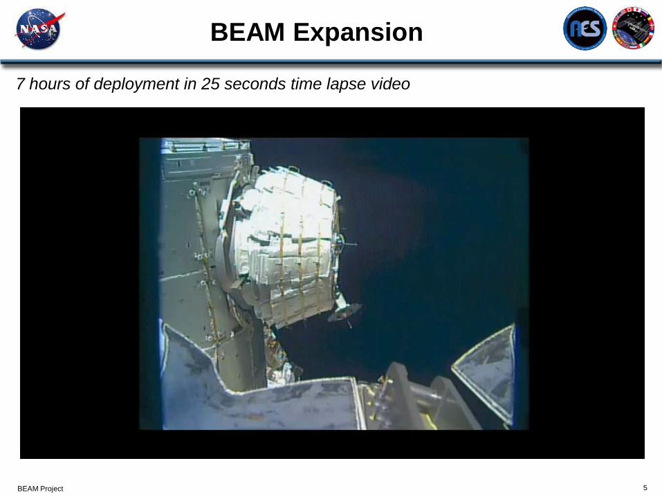
BEAM Expansion
5
7 hours of deployment in 25 seconds time lapse video
BEAM Project
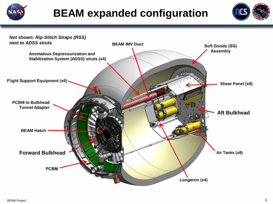
BEAM expanded configuration
6
Air Tanks (x8)
BEAM Hatch
Forward Bulkhead
PCBM to Bulkhead
Tunnel Adapter
Anomalous Depressurization and
Stabilization System (ADSS) struts (x4)
BEAM IMV Duct
Shear Panel (x8)
Aft Bulkhead
Not shown: Rip-Stitch Straps (RSS)
next to ADSS struts
BEAM Project
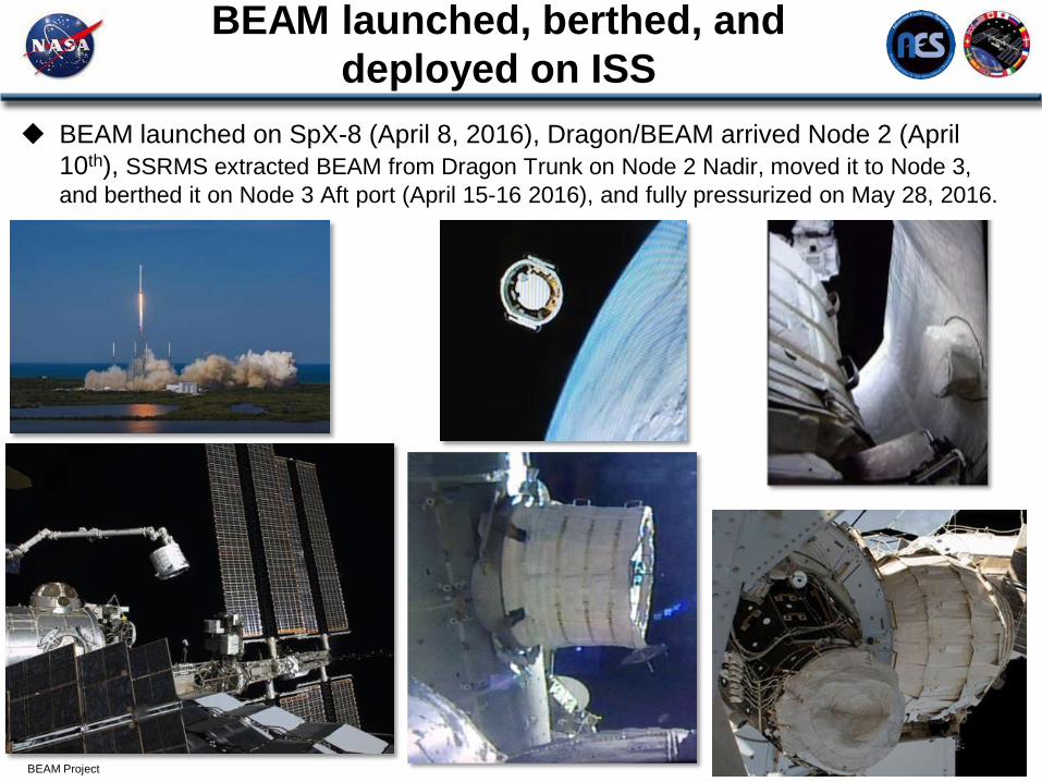
BEAM launched, berthed, and
deployed on ISS
BEAM launched on SpX-8 (April 8, 2016), Dragon/BEAM arrived Node 2 (April
10th), SSRMS extracted BEAM from Dragon Trunk on Node 2 Nadir, moved it to Node 3,
and berthed it on Node 3 Aft port (April 15-16 2016), and fully pressurized on May 28, 2016.
7
8
Ingress #4
Ingress #1-#3
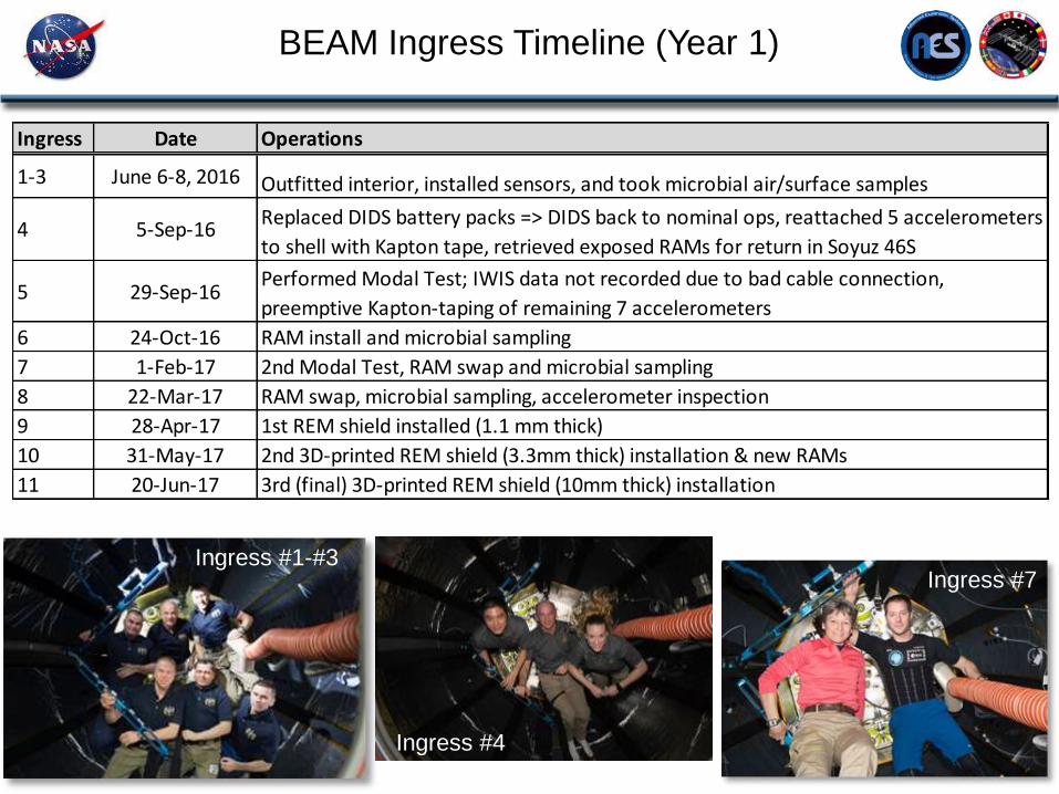
BEAM Ingress Timeline (Year 1)
Ingress #7
Ingress Date Operations
1-3 June 6-8, 2016 Outfitted interior, installed sensors, and took microbial air/surface samples
4 5-Sep-16Replaced DIDS battery packs => DIDS back to nominal ops, reattached 5 accelerometers
to shell with Kapton tape, retrieved exposed RAMs for return in Soyuz 46S
5 29-Sep-16Performed Modal Test; IWIS data not recorded due to bad cable connection,
preemptive Kapton-taping of remaining 7 accelerometers
6 24-Oct-16 RAM install and microbial sampling
7 1-Feb-17 2nd Modal Test, RAM swap and microbial sampling
8 22-Mar-17 RAM swap, microbial sampling, accelerometer inspection
9 28-Apr-17 1st REM shield installed (1.1 mm thick)
10 31-May-17 2nd 3D-printed REM shield (3.3mm thick) installation & new RAMs
11 20-Jun-17 3rd (final) 3D-printed REM shield (10mm thick) installation
BEAM Project
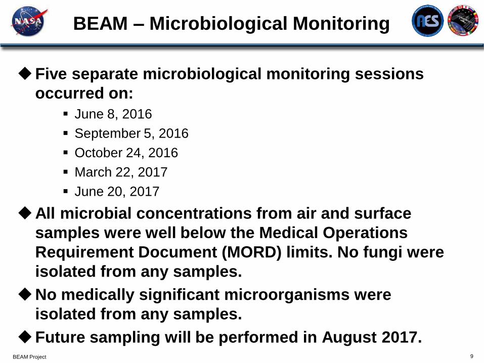
BEAM – Microbiological Monitoring
Five separate microbiological monitoring sessions
occurred on:
June 8, 2016
September 5, 2016
October 24, 2016
March 22, 2017
June 20, 2017
All microbial concentrations from air and surface
samples were well below the Medical Operations
Requirement Document (MORD) limits. No fungi were
isolated from any samples.
No medically significant microorganisms were
isolated from any samples.
Future sampling will be performed in August 2017.
9
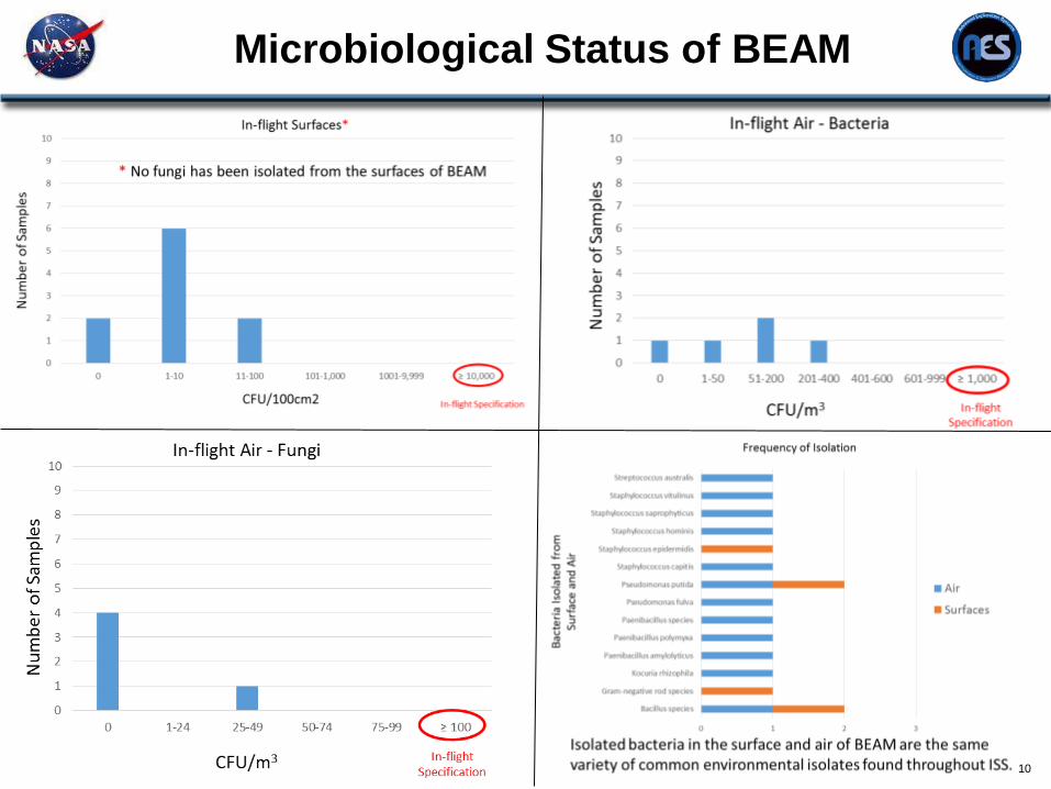
Microbiological Status of BEAM
10
BEAM Project 11
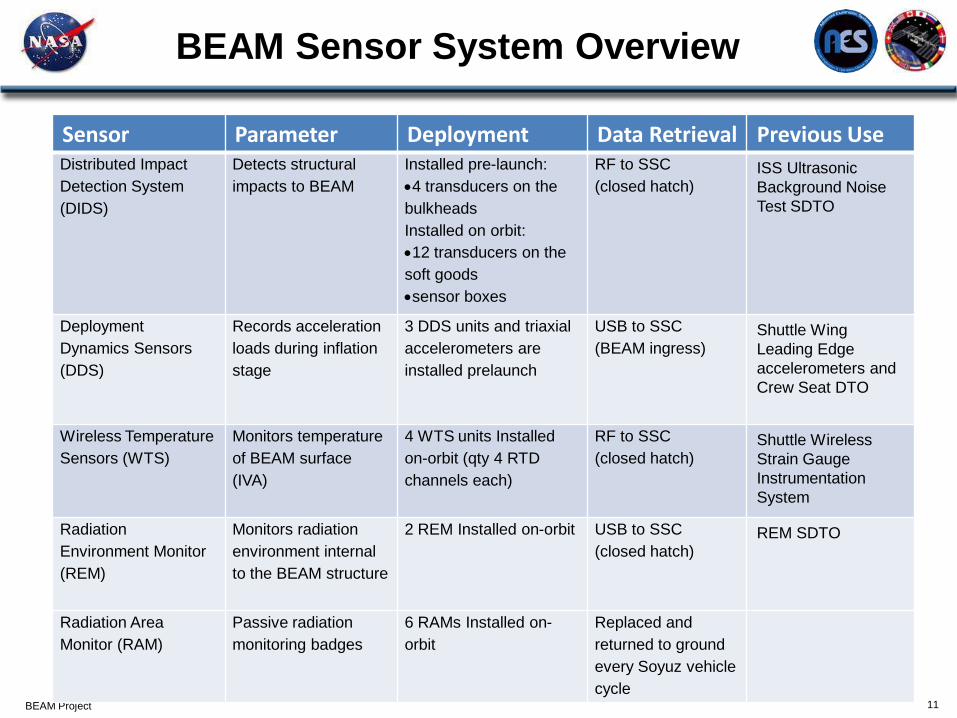
BEAM Sensor System Overview
Sensor Parameter Deployment Data Retrieval Previous Use Distributed Impact
Detection System
(DIDS)
Detects structural
impacts to BEAM
Installed pre-launch:
4 transducers on the
bulkheads
Installed on orbit:
12 transducers on the
soft goods
sensor boxes
RF to SSC
(closed hatch) ISS Ultrasonic
Background Noise
Test SDTO
Deployment
Dynamics Sensors
(DDS)
Records acceleration
loads during inflation
stage
3 DDS units and triaxial
accelerometers are
installed prelaunch
USB to SSC
(BEAM ingress) Shuttle Wing
Leading Edge
accelerometers and
Crew Seat DTO
Wireless Temperature
Sensors (WTS)
Monitors temperature
of BEAM surface
(IVA)
4 WTS units Installed
on-orbit (qty 4 RTD
channels each)
RF to SSC
(closed hatch) Shuttle Wireless
Strain Gauge
Instrumentation
System
Radiation
Environment Monitor
(REM)
Monitors radiation
environment internal
to the BEAM structure
2 REM Installed on-orbit USB to SSC
(closed hatch) REM SDTO
Radiation Area
Monitor (RAM)
Passive radiation
monitoring badges
6 RAMs Installed on-
orbit
Replaced and
returned to ground
every Soyuz vehicle
cycle
BEAM Project 12
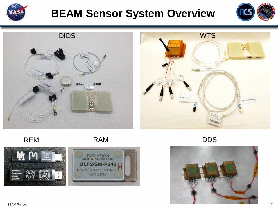
BEAM Sensor System Overview
DIDS WTS
REM RAM DDS
BEAM Project 13
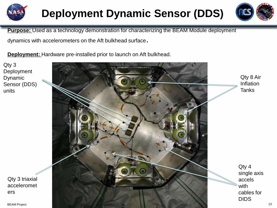
Deployment Dynamic Sensor (DDS)
Purpose: Used as a technology demonstration for characterizing the BEAM Module deployment
dynamics with accelerometers on the Aft bulkhead surface.
Deployment: Hardware pre-installed prior to launch on Aft bulkhead.
Qty 8 Air
Inflation
Tanks
Qty 3 triaxial
acceleromet
ers
Qty 3
Deployment
Dynamic
Sensor (DDS)
units
Qty 4
single axis
accels
with
cables for
DIDS
BEAM Project
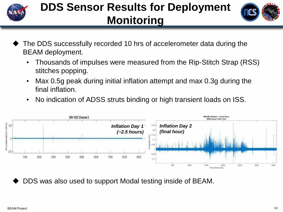
DDS Sensor Results for Deployment
Monitoring
14
The DDS successfully recorded 10 hrs of accelerometer data during the
BEAM deployment.
• Thousands of impulses were measured from the Rip-Stitch Strap (RSS)
stitches popping.
• Max 0.5g peak during initial inflation attempt and max 0.3g during the
final inflation.
• No indication of ADSS struts binding or high transient loads on ISS.
DDS was also used to support Modal testing inside of BEAM.
Inflation Day 1
(~2.5 hours)
Inflation Day 2
(final hour)
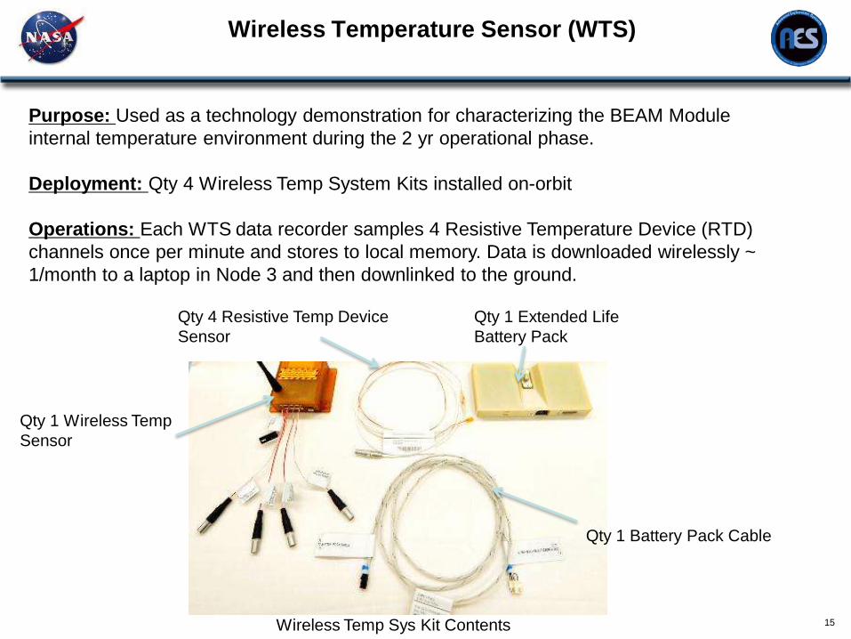
Wireless Temperature Sensor (WTS)
15
Purpose: Used as a technology demonstration for characterizing the BEAM Module
internal temperature environment during the 2 yr operational phase.
Deployment: Qty 4 Wireless Temp System Kits installed on-orbit
Operations: Each WTS data recorder samples 4 Resistive Temperature Device (RTD)
channels once per minute and stores to local memory. Data is downloaded wirelessly ~
1/month to a laptop in Node 3 and then downlinked to the ground.
Qty 1 Extended Life
Battery Pack
Qty 1 Wireless Temp
Sensor
Wireless Temp Sys Kit Contents
Qty 4 Resistive Temp Device
Sensor
Qty 1 Battery Pack Cable
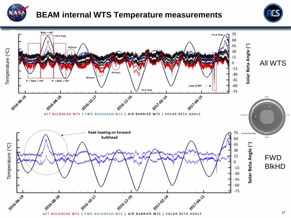
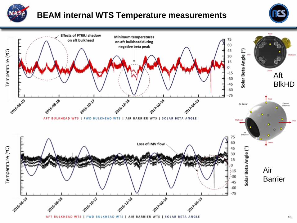
BEAM Thermal Performance
16
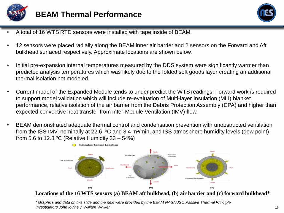
• A total of 16 WTS RTD sensors were installed with tape inside of BEAM.
• 12 sensors were placed radially along the BEAM inner air barrier and 2 sensors on the Forward and Aft
bulkhead surfaced respectively. Approximate locations are shown below.
• Initial pre-expansion internal temperatures measured by the DDS system were significantly warmer than
predicted analysis temperatures which was likely due to the folded soft goods layer creating an additional
thermal isolation not modeled.
• Current model of the Expanded Module tends to under predict the WTS readings. Forward work is required
to support model validation which will include re-evaluation of Multi-layer Insulation (MLI) blanket
performance, relative isolation of the air barrier from the Debris Protection Assembly (DPA) and higher than
expected convective heat transfer from Inter-Module Ventilation (IMV) flow.
• BEAM demonstrated adequate thermal control and condensation prevention with unobstructed ventilation
from the ISS IMV, nominally at 22.6 ºC and 3.4 m³/min, and ISS atmosphere humidity levels (dew point)
from 5.6 to 12.8 ºC (Relative Humidity 33 – 54%)
Locations of the 16 WTS sensors (a) BEAM aft bulkhead, (b) air barrier and (c) forward bulkhead*
* Graphics and data on this slide and the next were provided by the BEAM NASA/JSC Passive Thermal Principle
Investigators John Iovine & William Walker
17
BEAM internal WTS Temperature measurements Tem
pera
ture
(oC
) Tem
pera
ture
(oC
)
All WTS
FWD
BlkHD
18
BEAM internal WTS Temperature measurements Tem
pera
ture
(oC
) Tem
pera
ture
(oC
)
Air
Barrier
Aft
BlkHD
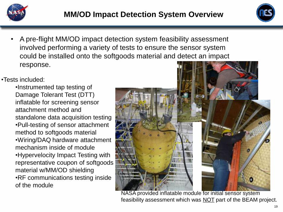
MM/OD Impact Detection System Overview
19
• A pre-flight MM/OD impact detection system feasibility assessment
involved performing a variety of tests to ensure the sensor system
could be installed onto the softgoods material and detect an impact
response.
•Tests included:
•Instrumented tap testing of
Damage Tolerant Test (DTT)
inflatable for screening sensor
attachment method and
standalone data acquisition testing
•Pull-testing of sensor attachment
method to softgoods material
•Wiring/DAQ hardware attachment
mechanism inside of module
•Hypervelocity Impact Testing with
representative coupon of softgoods
material w/MM/OD shielding
•RF communications testing inside
of the module
NASA provided inflatable module for initial sensor system
feasibility assessment which was NOT part of the BEAM project.
MM/OD Impact Detection System Overview
20
Demonstrated that the system recorded signal matched accurately with a
calibrated data acquisition system at White Sands Test Facility (WSTF).
Verified that adhesive attachment method for accelerometers to smooth
surfaces (Bladder) survives HVI impacts.
Velocity behavior of the restraint layer was determined (Anisotropic effects
and speed of sound measured).
Most of these HVI tests did not reach the restraint layer, and instead were
captured by the shielding layers. Since the shielding system was resting on
the restraint layer in these tests, the momentum from those impacts did
transfer into the restraint layer via the foam coupling.
Hypervelocity Impact (HVI) Testing Accomplishments
Distributed Impact Detection System Overview
21
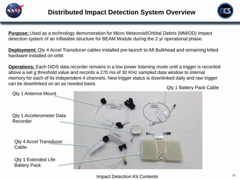
Purpose: Used as a technology demonstration for Micro Meteoroid/Orbital Debris (MM/OD) Impact
detection system of an inflatable structure for BEAM Module during the 2 yr operational phase.
Deployment: Qty 4 Accel Transducer cables installed pre-launch to Aft Bulkhead and remaining kitted
hardware installed on-orbit
Operations: Each DIDS data recorder remains in a low power listening mode until a trigger is recorded
above a set g threshold value and records a 270 ms of 30 KHz sampled data window to internal
memory for each of its independent 4 channels. New trigger status is downlinked daily and raw trigger
can be downlinked on an as needed basis.
Qty 1 Battery Pack Cable
Qty 1 Extended Life
Battery Pack
Qty 1 Accelerometer Data
Recorder
Qty 4 Accel Transducer
Cable
Impact Detection Kit Contents
Qty 1 Antenna Mount
Distributed Impact Detection System Overview
22
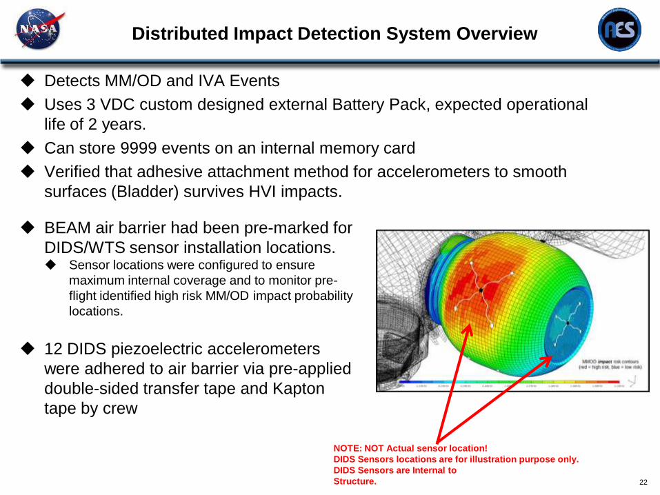
Detects MM/OD and IVA Events
Uses 3 VDC custom designed external Battery Pack, expected operational
life of 2 years.
Can store 9999 events on an internal memory card
Verified that adhesive attachment method for accelerometers to smooth
surfaces (Bladder) survives HVI impacts.
NOTE: NOT Actual sensor location!
DIDS Sensors locations are for illustration purpose only.
DIDS Sensors are Internal to
Structure.
BEAM air barrier had been pre-marked for
DIDS/WTS sensor installation locations. Sensor locations were configured to ensure
maximum internal coverage and to monitor pre-
flight identified high risk MM/OD impact probability
locations.
12 DIDS piezoelectric accelerometers
were adhered to air barrier via pre-applied
double-sided transfer tape and Kapton
tape by crew
DIDS Sensor Labeling/On-Orbit Installation
23
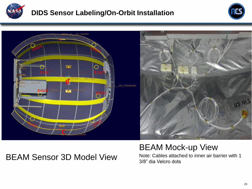
BEAM Sensor 3D Model View
BEAM Mock-up View Note: Cables attached to inner air barrier with 1
3/8” dia Velcro dots
B
B1W1 B2W2
B3W3B4W4
BEAM Impact Detection Performance Overview
24
Initial DIDS operations required engineering to tweak the trigger threshold
parameters to ensure DIDS accelerometers would not falsely trigger due to
low level ISS background noise being injected into the module structure.
Crew activity induced loads to structure have been routinely recorded during
previous crew ingresses in the module
DIDS operations had to be adjusted initially to disable an internal amplifier
which had been left active and was causing increased power consumption.
BEAM Impact Detection Performance Overview
25
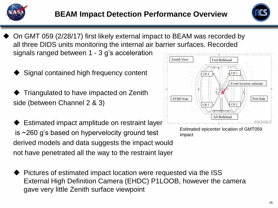
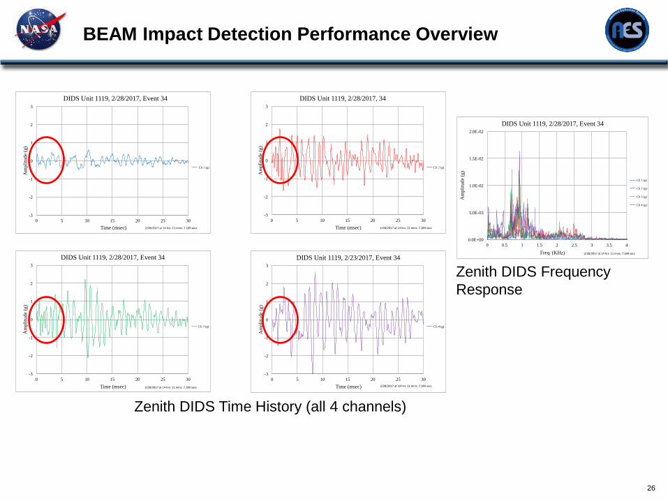
On GMT 059 (2/28/17) first likely external impact to BEAM was recorded by
all three DIDS units monitoring the internal air barrier surfaces. Recorded
signals ranged between 1 - 3 g’s acceleration
Signal contained high frequency content
Triangulated to have impacted on Zenith
side (between Channel 2 & 3)
Estimated impact amplitude on restraint layer
is ~260 g’s based on hypervelocity ground test
derived models and data suggests the impact would
not have penetrated all the way to the restraint layer
Pictures of estimated impact location were requested via the ISS
External High Definition Camera (EHDC) P1LOOB, however the camera
gave very little Zenith surface viewpoint
Estimated epicenter location of GMT059
impact
BEAM Impact Detection Performance Overview
26
-3
-2
-1
0
1
2
3
0 5 10 15 20 25 30
Am
pli
tude
(g)
Time (msec)
DIDS Unit 1119, 2/28/2017, 34
Ch 2 (g)
2/28/2017at14hrs:11mins:7.189secs
-3
-2
-1
0
1
2
3
0 5 10 15 20 25 30
Am
pli
tude
(g)
Time (msec)
DIDS Unit 1119, 2/28/2017, Event 34
Ch 3 (g)
2/28/2017at14hrs:11mins:7.189secs
-3
-2
-1
0
1
2
3
0 5 10 15 20 25 30
Am
pli
tude
(g)
Time (msec)
DIDS Unit 1119, 2/23/2017, Event 34
Ch 4 (g)
2/28/2017at14hrs:11mins:7.189secs
-3
-2
-1
0
1
2
3
0 5 10 15 20 25 30
Am
pli
tude
(g)
Time (msec)
DIDS Unit 1119, 2/28/2017, Event 34
Ch 1 (g)
2/28/2017at14hrs:11mins:7.189secs
0.0E+00
5.0E-03
1.0E-02
1.5E-02
2.0E-02
0 0.5 1 1.5 2 2.5 3 3.5 4
Am
pli
tude
(g)
Freq. (KHz)
DIDS Unit 1119, 2/28/2017, Event 34
Ch 1 (g)
Ch 2 (g)
Ch 3 (g)
Ch 4 (g)
2/28/2017at14hrs:11mins:7.189secs
Zenith DIDS Frequency
Response
Zenith DIDS Time History (all 4 channels)
Modal Test
27
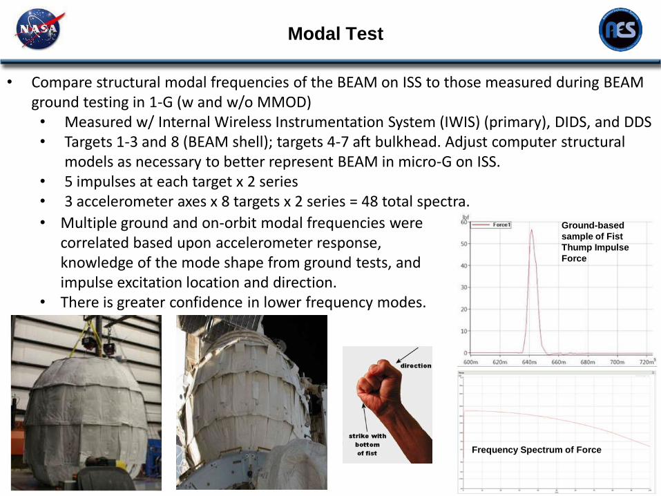
• Compare structural modal frequencies of the BEAM on ISS to those measured during BEAM ground testing in 1-G (w and w/o MMOD) • Measured w/ Internal Wireless Instrumentation System (IWIS) (primary), DIDS, and DDS • Targets 1-3 and 8 (BEAM shell); targets 4-7 aft bulkhead. Adjust computer structural
models as necessary to better represent BEAM in micro-G on ISS. • 5 impulses at each target x 2 series • 3 accelerometer axes x 8 targets x 2 series = 48 total spectra.
Ground-based
sample of Fist
Thump Impulse
Force
Frequency Spectrum of Force
• Multiple ground and on-orbit modal frequencies were correlated based upon accelerometer response, knowledge of the mode shape from ground tests, and impulse excitation location and direction.
• There is greater confidence in lower frequency modes.
Modal Test- Preliminary Results and Forward Work
28
• Preliminary Results
• Large frequency differences between the on-orbit and ground-based tests for
the first three modes: the first lateral bending modes are 10 – 14% higher and
the first torsion mode is 28% higher on-orbit than in ground tests. Possible
reasons for these differences include the following:
• MMOD layer interaction with the BEAM restraint layer/wall is different on-
orbit than under 1-G ground test conditions. Performing ground tests with
and without MMOD was valuable for showing this.
• The spaceflight article and the ground test article have different masses.
The first two mode frequencies are higher than in ground-based tests,
even without MMOD installed.
• The ISS interface with BEAM is different from the ground-based test.
• Forward work
• Compare modal frequencies of the ISS-attached BEAM loads model to on-orbit
test frequencies.
• Investigate modelling techniques for attaching MMOD layers
• Investigate mass differences and perform an operational modal analysis (OMA)
• Perform a similar analysis on the DDS, DIDS, and Camera Microphone data.
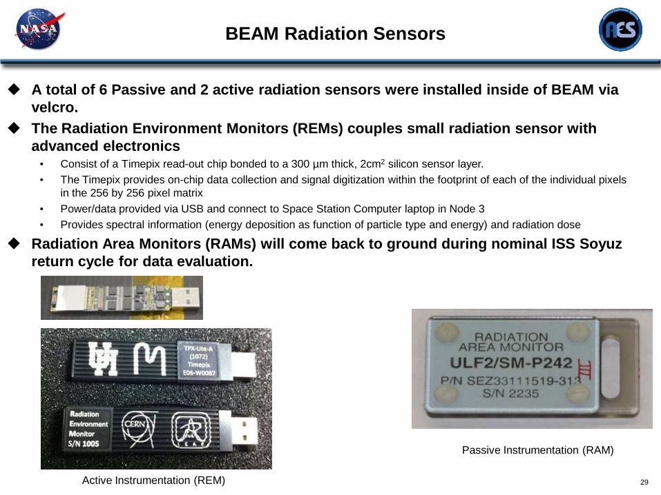
BEAM Radiation Sensors
29
A total of 6 Passive and 2 active radiation sensors were installed inside of BEAM via
velcro.
The Radiation Environment Monitors (REMs) couples small radiation sensor with
advanced electronics • Consist of a Timepix read-out chip bonded to a 300 µm thick, 2cm2 silicon sensor layer.
• The Timepix provides on-chip data collection and signal digitization within the footprint of each of the individual pixels
in the 256 by 256 pixel matrix
• Power/data provided via USB and connect to Space Station Computer laptop in Node 3
• Provides spectral information (energy deposition as function of particle type and energy) and radiation dose
Radiation Area Monitors (RAMs) will come back to ground during nominal ISS Soyuz
return cycle for data evaluation.
Passive Instrumentation (RAM)
Active Instrumentation (REM)

Radiation Performance
30
Radiation (REM) initial results
• System has been operating without issues since installation (although GUI
needs to be relaunched on a weekly basis due to scheduled laptop reboots.
• Galactic Cosmic Ray (GCR) dose rate similar to other ISS modules
• As expected, REMs measured higher trapped field dose rate — e.g., in South
Atlantic Anomaly (SAA) — inside BEAM than in other ISS modules due to
thinner shell and lack of equipment racks in BEAM technology demonstrator
• Currently an additional test is underway to determine if the particles being
measured inside of BEAM are of low energy and if so, can they be effectively
shielded out with 3D printed plastic hemispheres of various thicknesses (1.1mm,
3.3 mm & 10mm.
3D printed hemispheres were printed with the on-board ISS
”Made in Space” 3D printer
• BEAM tech demo data will be used to assess shielding requirements for
expandable habitat modules configured for human exploration missions
Future Plans & Summary
31
Future Plans
BEAM was originally planned for a 2 yr operational mission to demonstrate
and advance the technology with infrequent human ingresses.
• ISS management is evaluating options for using BEAM as a long-term
hardware stowage module which would require extending the two year
life and reconfiguration of the wireless instrumentation communication &
additional batteries.
Summary
Overall BEAM has been performing beyond expectations!
BEAM will help advance the human rated expandable module to TRL 9 and
in the future should be considered as a solution for volume/mass savings in
future planetary and space exploration applications.
Use BEAM sensor data and lessons learned to fold into future expandable
module design
• Evaluate methods to embed sensors into softgoods material during
fabrication process that would not risk damage to the module during
compression/expansion phases to reduce crew time for installation.
Team Acknowledgements
32
The authors of this presentation would like to provide a special thanks to the
entire BEAM project team and Bigelow Aerospace.
Specifically the authors would like to acknowledge the following people who
provided BEAM specific performance data:
• Microbial Monitoring Performance – Ariel Macatangay, William Misek & Melanie
Smith
• Deployment Dynamics & Modal Test Results – Michael Grygier
• Thermal Performance – John Iovine & Dr. William Walker
• MM/OD Monitoring Performance – Dr. Eric Madaras
• Radiation Sensor System & Performance – Dr. Dan Fry and the entire Space
Radiation Analysis Group (SRAG)
BEAM Project
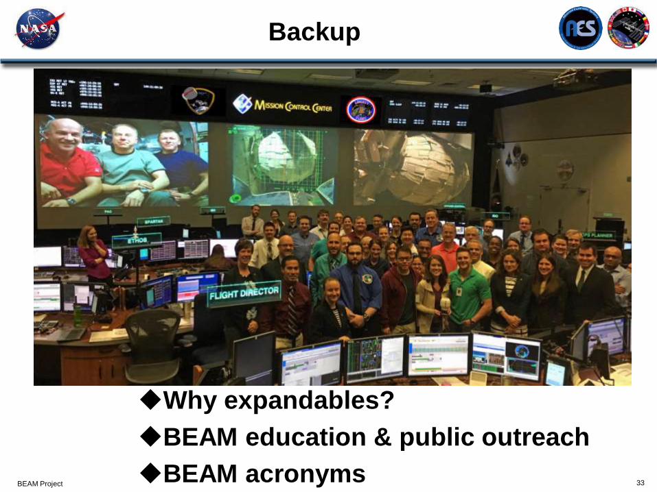
Backup
33
Why expandables?
BEAM education & public outreach
BEAM acronyms
BEAM Project
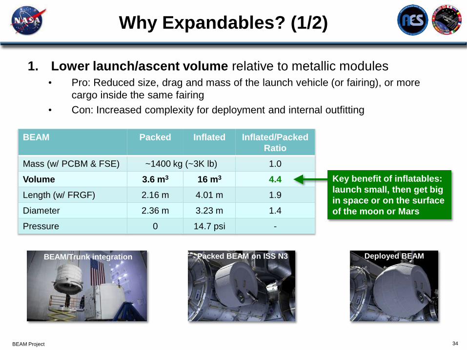
Why Expandables? (1/2)
34
BEAM Packed Inflated Inflated/Packed
Ratio
Mass (w/ PCBM & FSE) ~1400 kg (~3K lb) 1.0
Volume 3.6 m3 16 m3 4.4
Length (w/ FRGF) 2.16 m 4.01 m 1.9
Diameter 2.36 m 3.23 m 1.4
Pressure 0 14.7 psi -
Key benefit of inflatables:
launch small, then get big
in space or on the surface
of the moon or Mars
1. Lower launch/ascent volume relative to metallic modules
• Pro: Reduced size, drag and mass of the launch vehicle (or fairing), or more
cargo inside the same fairing
• Con: Increased complexity for deployment and internal outfitting
BEAM/Trunk integration Packed BEAM on ISS N3 Deployed BEAM

BEAM Project
Why Expandables? (2/2)
35
0
50
100
150
200
250
300
0 50 100 150 200 250 300 350 400
Den
sit
y =
Ma
ss
/Vo
lum
e (
kg
/m3)
Volume (m3)
Quick-Look Module Density Comparison
Expandable
Metallic
BEAM
BA330 design TransHab design
Genesis
Leonardo PMM
Skylab Orbital Workshop Kibo JEM Cygnus PCM (enhanced)
2. Less mass for the same volume as metallic modules? Maybe. • Depends upon mission and design requirements, outfitting, materials, size, etc.
• Current expandable module experience only at low volumes, not mass-optimized
• Small, mass-optimized metallic modules can be less dense than robust BEAM tech demo
• Large expandable module designs potentially offer lower density due to much greater
specific strength of fabrics vs. metal alloys, though this must be proven in flight
• More experience with expandable modules may reduce mass due to reduced factor of
safety (e.g., ISS requires FoS = 4.0 for fabric structures, 2.0 for aluminum)
Other ISS modules
BEAM Project
Education and Public Outreach
BEAM full-size mockup in B.9 at JSC
(publicly visible on the Space Center Houston Red Tour)
NASA Twitter & Facebook posts, Facebook Live, Reddit AMA
TV, radio and print media interviews and articles • NASA TV Space Station Live interview
• Aerospace Daily & Defense Report
• The Economist article, “Pump it up, Scotty”, described BEAM as “bouncy castles in space”
• 60 Minutes aired segment with Robert Bigelow and Bigelow Aerospace
Online articles • Bigelow Aerospace BEAM page: http://bigelowaerospace.com/beam/
• NASA Feature: http://www.nasa.gov/mission_pages/station/news/beam_feature.html
• NASA Landing Page: http://cms.nasa.gov/content/bigelow-expandable-activity-module
• NASA Announcement:
http://www.nasa.gov/home/hqnews/2013/jan/HQ_13-024_Bigelow_ISS_Module.html
• Space News: http://spacenews.com/bigelow-module-ready-to-fly-to-space-station/
• American Airlines magazine: http://magazines.aa.com/content/beam-me
36
BEAM installation animation by JSC/IGOAL on YouTube
https://youtu.be/VopaBsuwikk
BEAM Project
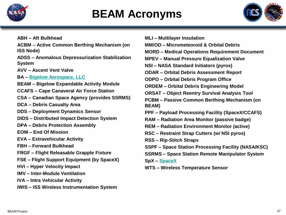
BEAM Acronyms
ABH – Aft Bulkhead
ACBM – Active Common Berthing Mechanism (on
ISS Node)
ADSS – Anomalous Depressurization Stabilization
System
AVV – Ascent Vent Valve
BA – Bigelow Aerospace, LLC
BEAM – Bigelow Expandable Activity Module
CCAFS – Cape Canaveral Air Force Station
CSA – Canadian Space Agency (provides SSRMS)
DCA – Debris Casualty Area
DDS – Deployment Dynamics Sensor
DIDS – Distributed Impact Detection System
DPA – Debris Protection Assembly
EOM – End Of Mission
EVA – Extravehicular Activity
FBH – Forward Bulkhead
FRGF – Flight Releasable Grapple Fixture
FSE – Flight Support Equipment (by SpaceX)
HVI – Hyper Velocity Impact
IMV – Inter-Module Ventilation
IVA – Intra Vehicular Activity
IWIS – ISS Wireless Instrumentation System
MLI – Multilayer Insulation
MM/OD – Micrometeoroid & Orbital Debris
MORD – Medical Operations Requirement Document
MPEV – Manual Pressure Equalization Valve
NSI – NASA Standard Initiators (pyros)
ODAR – Orbital Debris Assessment Report
ODPO – Orbital Debris Program Office
ORDEM – Orbital Debris Engineering Model
ORSAT – Object Reentry Survival Analysis Tool
PCBM – Passive Common Berthing Mechanism (on
BEAM)
PPF – Payload Processing Facility (SpaceX/CCAFS)
RAM – Radiation Area Monitor (passive badge)
REM – Radiation Environment Monitor (active)
RSC – Restraint Strap Cutters (w/ NSI pyros)
RSS – Rip-Stitch Straps
SSPF – Space Station Processing Facility (NASA/KSC)
SSRMS – Space Station Remote Manipulator System
SpX – SpaceX
WTS – Wireless Temperature Sensor
37