
BIG-IP Reference Guideytan/i450-02/materials/bigip_ref.pdf · Reference Guide i Service and Support...
377
BIG-IP ® Reference Guide version 4.0 MAN-0036-00
Transcript of BIG-IP Reference Guideytan/i450-02/materials/bigip_ref.pdf · Reference Guide i Service and Support...

BIG-IP® Reference Guide
version 4.0
MAN-0036-00

Service and Support Information
Product VersionThis manual applies to version 4.0 of the BIG-IP® Controller.
Obtaining Technical Support
Contacting F5 Networks
Web tech.f5.com
Phone (206) 272-6888
Fax (206) 272-6802
Email (support issues)
Email (suggestions) [email protected]
Web www.f5.com
Toll-free phone (888) 961-7242
Corporate phone (206) 272-5555
Fax (206) 272-5556
Email [email protected]
Mailing Address 401 Elliott Avenue WestSeattle, Washington 98119
Reference Guide i

Legal Notices
Copyright
F5 Networks, Inc. (F5) believes the information it furnishes to be accurate and reliable. However, F5 assumes no responsibility for the use of this information, nor any infringement of patents or other rights of third parties which may result from its use. No license is granted by implication or otherwise under any patent, copyright, or other intellectual property right of F5 except as specifically described herein. F5 reserves the right to change specifications at any time without notice.
Copyright 1997-2001, F5 Networks, Inc. All rights reserved.
Trademarks
F5, BIG-IP, 3-DNS, SEE-IT, and GLOBAL-SITE are registered trademarks of F5 Networks, Inc. EDGE-FX, iControl, and FireGuard are trademarks of F5 Networks, Inc. Other product and company names are registered trademarks or trademarks of their respective holders.
Export Regulation Notice
The BIG-IP® Controller may include cryptographic software. Under the Export Administration Act, the United States government may consider it a criminal offense to export this BIG-IP® Controller from the United States.
Export Warning
This is a Class A product. In a domestic environment this product may cause radio interference in which case the user may be required to take adequate measures.
FCC Compliance
This equipment generates, uses, and may emit radio frequency energy. The equipment has been type tested and found to comply with the limits for a Class A digital device pursuant to Part 15 of FCC rules, which are designed to provide reasonable protection against such radio frequency interference.
Operation of this equipment in a residential area may cause interference, in which case the user at his own expense will be required to take whatever measures may be required to correct the interference.
Any modifications to this device, unless expressly approved by the manufacturer, can void the user's authority to operate this equipment under part 15 of the FCC rules.
Canadian Regulatory Compliance
This class A digital apparatus complies with Canadian I CES-003.
Standards Compliance
The product conforms to ANSI/UL Std 1950 and Certified to CAN/CSA Std. C22.2 No. 950.
ii BIG-IP® Controller 4.0

Acknowledgments
This product includes software developed by the University of California, Berkeley and its contributors.
This product includes software developed by the Computer Systems Engineering Group at the Lawrence Berkeley Laboratory.
This product includes software developed by the NetBSD Foundation, Inc. and its contributors.
This product includes software developed by Christopher G. Demetriou for the NetBSD Project.
This product includes software developed by Adam Glass.
This product includes software developed by Christian E. Hopps.
This product includes software developed by Dean Huxley.
This product includes software developed by John Kohl.
This product includes software developed by Paul Kranenburg.
This product includes software developed by Terrence R. Lambert.
This product includes software developed by Philip A. Nelson.
This product includes software developed by Herb Peyerl.
This product includes software developed by Jochen Pohl for the NetBSD Project.
This product includes software developed by Chris Provenzano.
This product includes software developed by Theo de Raadt.
This product includes software developed by David Muir Sharnoff.
This product includes software developed by SigmaSoft, Th. Lockert.
This product includes software developed for the NetBSD Project by Jason R. Thorpe.
This product includes software developed by Jason R. Thorpe for And Communications, http://www.and.com.
This product includes software developed for the NetBSD Project by Frank Van der Linden.
This product includes software developed for the NetBSD Project by John M. Vinopal.
This product includes software developed by Christos Zoulas.
This product includes software developed by Charles Hannum.
This product includes software developed by Charles Hannum, by the University of Vermont and State Agricultural College and Garrett A. Wollman, by William F. Jolitz, and by the University of California, Berkeley, Lawrence Berkeley Laboratory, and its contributors.
This product includes software developed by the University of Vermont and State Agricultural College and Garrett A. Wollman.
In the following statement, "This software" refers to the Mitsumi CD-ROM driver: This software was developed by Holger Veit and Brian Moore for use with "386BSD" and similar operating systems. "Similar operating systems" includes mainly non-profit oriented systems for research and education, including but not restricted to "NetBSD," "FreeBSD," "Mach" (by CMU).
In the following statement, "This software" refers to the parallel port driver: This software is a component of "386BSD" developed by William F. Jolitz, TeleMuse.
Reference Guide iii

This product includes software developed by the Apache Group for use in the Apache HTTP server project (http://www.apache.org/).
This product includes software developed by Darren Reed. (© 1993-1998 by Darren Reed).
This product includes software licensed from Richard H. Porter under the GNU Library General Public License (© 1998, Red Hat Software), www.gnu.org/copyleft/lgpl.html.
This product includes the standard version of Perl software licensed under the Perl Artistic License (© 1997, 1998 Tom Christiansen and Nathan Torkington). All rights reserved. You may find the most current standard version of Perl at http://www.perl.com.
iv BIG-IP® Controller 4.0

Table of Contents
Table of Contents
IntroductionGetting started ....................................................................................................... Intro-1
Choosing a configuration tool ................................................................... Intro-1Using the Administrator Kit ............................................................................... Intro-2
Stylistic conventions .................................................................................... Intro-3Finding additional help and technical support resources .................... Intro-6
What’s new in version 4.0 ................................................................................... Intro-73-DNS on the BIG-IP Controller ............................................................. Intro-7OneConnect™ content switching with HTTP Keep-Alives .............. Intro-7Bridging and Layer 2 forwarding ............................................................... Intro-7HTTP Redirect pool property .................................................................. Intro-8Load balance any IP protocol .................................................................... Intro-8Link aggregation and fail-over .................................................................... Intro-8On-the-fly content converter .................................................................... Intro-8SNAT automap feature ............................................................................... Intro-9Health monitors ........................................................................................... Intro-9Performance monitors ................................................................................ Intro-9Default controller configuration ............................................................... Intro-9Web-based Configuration utility enhancements .................................Intro-10
Learning more about the BIG-IP Controller product family .....................Intro-10
1Configuring the BIG-IP Controller
Introduction ...................................................................................................................1-1Pools ................................................................................................................................1-2Load Balancing ...............................................................................................................1-4
Understanding individual load balancing modes ...........................................1-6Setting the load balancing method for a pool ...............................................1-9Setting ratio weights and priority levels for node addresses ..................1-11Configuring servers and the BIG-IP Controller for Dynamic Ratio load balancing ..........................................................................................1-12
Setting up persistence for a pool ............................................................................1-22Basic types of persistence ...............................................................................1-22Advanced types of Persistence .......................................................................1-23Setting up SSL persistence ...............................................................................1-23Setting up simple persistence .........................................................................1-25Using HTTP cookie persistence ....................................................................1-26Using destination address affinity (sticky persistence) .............................1-32Using a simple timeout and a persist mask on a pool ..............................1-34Maintaining persistence across virtual servers that use the same virtual addresses .....................................................................................1-35Maintaining persistence across all virtual servers ......................................1-36HTTP redirect (specifying a fallback host) ..................................................1-38
Reference Guide vii

Table of Contents
Rules ..............................................................................................................................1-40Pool selection based on HTTP request data ..............................................1-40Pool selection based on IP packet header information ............................1-41
Rule statements ..........................................................................................................1-42Questions (expressions) ..................................................................................1-43Constant operands ...........................................................................................1-43Variable operands (variables) .........................................................................1-43HTTP request string variables ........................................................................1-45Configuring rules ...............................................................................................1-47Configuring virtual servers that reference rules ........................................1-47
Cache statement syntax ............................................................................................1-50Configuring a remote origin server ..............................................................1-52
Additional rule examples ..........................................................................................1-54Cookie rule .........................................................................................................1-54Language rule ......................................................................................................1-55Cache rule ...........................................................................................................1-55AOL rule .............................................................................................................1-56IP protocol specific rule ...................................................................................1-57
Virtual servers .............................................................................................................1-58Using standard or wildcard virtual servers ..........................................................1-59
Defining virtual servers ....................................................................................1-59Defining wildcard virtual servers ...................................................................1-60
Configuring a network virtual server ....................................................................1-64Mirroring virtual server state ..................................................................................1-65Additional virtual server options ............................................................................1-66
Using additional BIG-IP Controller features with virtual servers ..........1-72Proxies ..........................................................................................................................1-73
Creating a content converter gateway from the command line ............1-74Disabling VLANs for a gateway ......................................................................1-76
Nodes ............................................................................................................................1-78Services .........................................................................................................................1-82Address translation & forwarding ...........................................................................1-86NATs .............................................................................................................................1-87
Defining a network address translation (NAT) ..........................................1-88Additional restrictions ......................................................................................1-90
SNATs ...........................................................................................................................1-90Setting SNAT global properties .....................................................................1-91Configuring SNAT address mappings ...........................................................1-92Enabling or disabling SNAT automap ...........................................................1-94
Forwarding ...................................................................................................................1-97Forwarding virtual servers ..............................................................................1-98IP forwarding ......................................................................................................1-99
VLANs, self IPs, interfaces & trunks .................................................................... 1-102VLANs ........................................................................................................................ 1-102
viii BIG-IP® Controller 4.0

Table of Contents
Default VLAN mapping with grouping ...................................................... 1-104Creating, renaming, and deleting VLANs .................................................. 1-106VLAN group .................................................................................................... 1-107Tagging VLANs ............................................................................................... 1-108Setting up security for VLANs .................................................................... 1-110Setting fail-safe timeouts for VLANs .......................................................... 1-110Setting the MAC masquerade address ...................................................... 1-111
Self IP address ........................................................................................................... 1-113Enabling or disabling SNAT automap ........................................................ 1-114
Interface ..................................................................................................................... 1-115Interface naming convention ........................................................................ 1-115Displaying status for interfaces ................................................................... 1-117Setting the media type ................................................................................... 1-117Setting the duplex mode ............................................................................... 1-118
Trunks ........................................................................................................................ 1-118Health monitors ....................................................................................................... 1-120Selecting the monitor template ............................................................................ 1-122
Working with templates for simple monitors ......................................... 1-123Working with templates for ECV monitors ............................................ 1-125Working with templates for EAV monitors ............................................. 1-127
Configuring a monitor ............................................................................................ 1-132Entering string values ..................................................................................... 1-135Setting destinations ........................................................................................ 1-136Using send, receive, url, and get statements ............................................ 1-136Using transparent and reverse modes ...................................................... 1-137Testing SQL service checks ......................................................................... 1-138Running user-added EAVs ............................................................................ 1-139Showing, disabling, and deleting monitors ................................................ 1-140
Associating the monitor with a node or nodes ............................................... 1-143Reviewing types of association .................................................................... 1-144Showing and deleting associations .............................................................. 1-149
Redundant systems ................................................................................................. 1-152Synchronizing configurations between controllers ......................................... 1-153Configuring fail-safe settings ................................................................................. 1-155
Arming fail-safe on a VLAN ......................................................................... 1-155Mirroring connection and persistence information ......................................... 1-157
Commands for mirroring ............................................................................. 1-158Mirroring virtual server state ...................................................................... 1-159Mirroring SNAT connections ...................................................................... 1-159
Using gateway fail-safe ............................................................................................ 1-160Adding a gateway fail-safe check ................................................................. 1-160
Using network-based fail-over ............................................................................. 1-163Setting a specific BIG-IP Controller to be the preferred active unit ........... 1-164Setting up active-active redundant controllers ................................................. 1-165
Reference Guide ix

Table of Contents
Configuring an active-active system ........................................................... 1-166Understanding active-active system fail-over ........................................... 1-172Introducing additional active-active BIG/db configuration parameters ....................................................................................................... 1-174Reviewing specific active-active bigpipe commands ............................... 1-175Returning an active-active installation to active/standby mode ........... 1-176
Filters .......................................................................................................................... 1-177IP filters ...................................................................................................................... 1-178
Configuring IP filters ...................................................................................... 1-178Rate filters and rate classes ................................................................................... 1-179
Configuring rate filters and rate classes .................................................... 1-179
2bigpipe Command Reference
bigpipe commands ........................................................................................................2-1-? .......................................................................................................................................2-4config ...............................................................................................................................2-5
Synchronizing configuration files ......................................................................2-5Saving configuration files to an archive ..........................................................2-6Installing an archived configuration file ...........................................................2-6
conn .................................................................................................................................2-7failover ............................................................................................................................2-8global ...............................................................................................................................2-9-h and -help ..................................................................................................................2-17interface ........................................................................................................................2-18
Setting the media type ......................................................................................2-18Setting the duplex mode ..................................................................................2-18
load ................................................................................................................................2-19maint ..............................................................................................................................2-20makecookie ..................................................................................................................2-21merge ............................................................................................................................2-22monitor .........................................................................................................................2-23
Showing, disabling, and deleting monitors ...................................................2-23Monitor templates .............................................................................................2-24Send, receive and get statements ..................................................................2-29Transparent and reverse modes ....................................................................2-30Testing SQL service checks ............................................................................2-31Running user-added EAVs ...............................................................................2-32Node and port aliasing .....................................................................................2-33Using wildcards to specify node addresses and ports ..............................2-35
-n ....................................................................................................................................2-36nat ..................................................................................................................................2-37
Defining a NAT ..................................................................................................2-37
x BIG-IP® Controller 4.0

Table of Contents
Disabling VLANs for a NAT ...........................................................................2-39Viewing a controller’s unit ID number .........................................................2-39Disabling ARP requests ....................................................................................2-39
node ...............................................................................................................................2-40Marking nodes and node ports up and down .............................................2-41Setting connection limits for nodes and node addresses .........................2-41Displaying status of all nodes ..........................................................................2-42Associating a health monitor with a node ...................................................2-43
pool ................................................................................................................................2-45 Creating a pool .................................................................................................2-45Activating HTTP cookie persistence ............................................................2-48Activating sticky persistence ...........................................................................2-51Activating SSL persistence ...............................................................................2-52Specifying priority based member activation ..............................................2-52Specifying a fallback host for HTTP redirect ..............................................2-54
proxy .............................................................................................................................2-56Creating an SSL gateway ..................................................................................2-56Configuring a content converter ...................................................................2-57Disabling ARP requests ....................................................................................2-59Enabling, disabling, or deleting a gateway ....................................................2-59Disabling VLANs for a gateway ......................................................................2-59Displaying gateway configuration information ............................................2-60Adding a last hop pool to a gateway from the command line ................2-60
ratio ...............................................................................................................................2-62Setting ratio weight for one or more node addresses .............................2-62
reset ...............................................................................................................................2-64rule .................................................................................................................................2-65
Creating rules .....................................................................................................2-65Associating a rule with virtual server ...........................................................2-66Rule elements .....................................................................................................2-66
save ................................................................................................................................2-68self ..................................................................................................................................2-69
Self IP addresses and SNAT auto-mapping ..................................................2-70service ...........................................................................................................................2-71
Setting connection limits on services ...........................................................2-71Displaying service settings ...............................................................................2-72Configuring TCP services ................................................................................2-72Configuring UDP services ...............................................................................2-73
snat .................................................................................................................................2-74Defining the default SNAT ..............................................................................2-75Creating individual SNAT addresses ............................................................2-75Creating a network SNAT address ...............................................................2-75SNAT auto-mapping .........................................................................................2-76Deleting SNAT Addresses ..............................................................................2-76
Reference Guide xi

Table of Contents
Disabling VLANs for a SNAT .........................................................................2-76Showing SNAT mappings ................................................................................2-76Limiting connections .........................................................................................2-77Enabling mirroring for redundant systems ..................................................2-77Setting idle connection timeouts ...................................................................2-77Disabling ARP requests ....................................................................................2-78Clearing statistics ..............................................................................................2-78
summary .......................................................................................................................2-79trunk ..............................................................................................................................2-81
Creating a trunk ................................................................................................2-81unit .................................................................................................................................2-83verbose .........................................................................................................................2-84verify ..............................................................................................................................2-86version ...........................................................................................................................2-87virtual .............................................................................................................................2-88
Defining a virtual server ...................................................................................2-88Displaying information about virtual servers ..............................................2-89Disabling VLANs for a virtual server ............................................................2-90Disabling ARP requests ....................................................................................2-90Setting a user-defined netmask and broadcast for a network virtual server ......................................................................................................2-90Setting a connection limit ................................................................................2-92Setting translation properties for virtual addresses and ports ...............2-92Setting up last hop pools for virtual servers ...............................................2-92Mirroring virtual server state .........................................................................2-93Enabling and disabling a virtual server ..........................................................2-94Enabling and disabling a virtual address ........................................................2-94Displaying information about virtual addresses .........................................2-95Deleting a virtual server ..................................................................................2-95Turning software acceleration off for virtual servers using IPFW rate filters ............................................................................................................2-95Enabling and disabling Any IP ..........................................................................2-96
vlan .................................................................................................................................2-97Creating and assigning a VLAN ......................................................................2-99Tagged VLANs ...................................................................................................2-99Enabling and disabling port lockdown ....................................................... 2-100Setting the fail-over timeout and arming the fail-safe ............................ 2-100Enabling and disabling SNAT auto-mapping ............................................. 2-101Setting the MAC masquerade address ...................................................... 2-102
vlangroup ................................................................................................................... 2-104
xii BIG-IP® Controller 4.0

Table of Contents
3BIG-IP Controller Base Configuration Tools
Introducing the BIG-IP Controller base configuration tools ..............................3-1config ...............................................................................................................................3-3
Selecting a keyboard ...........................................................................................3-3Product selection ................................................................................................3-4Defining a root password ..................................................................................3-4Defining a host name ..........................................................................................3-5Configuring a default route ...............................................................................3-5Setting up a redundant system .........................................................................3-5Configuring interfaces ........................................................................................3-6Defining VLANs and IP addresses ...................................................................3-7Assigning interfaces to VLANs .........................................................................3-7Selecting the primary IP address ......................................................................3-8Configuring settings for remote web access .................................................3-8Configuring a time zone .....................................................................................3-9Configuring the DNS forwarding proxy settings .......................................3-10Configuring remote command line access ..................................................3-10NTP support .......................................................................................................3-11NameSurfer ........................................................................................................3-11
config combo ...............................................................................................................3-12config dns ......................................................................................................................3-13config ftpd .....................................................................................................................3-14config httpd ..................................................................................................................3-15config password ..........................................................................................................3-16config redundant .........................................................................................................3-17config remote ..............................................................................................................3-18config rshd ....................................................................................................................3-19config sshd ....................................................................................................................3-20config telnetd ...............................................................................................................3-21config timezone ...........................................................................................................3-22
4BIG/db Configuration Keys
Supported BIG/db configuration keys ......................................................................4-1Displaying current setting of a BIG/db configuration key ..........................4-1Setting a BIG/db configuration key ..................................................................4-2Unsetting a BIG/db configuration key .............................................................4-2Failover and Cluster keys ..................................................................................4-2StateMirror keys ..................................................................................................4-4
Reference Guide xiii

Table of Contents
Using Gateway Pinger keys ...............................................................................4-6Bigd keys ................................................................................................................4-6Other keys ............................................................................................................4-8
5Configuration Files
Glossary
Index
xiv BIG-IP® Controller 4.0

Introduction
• Getting started
• Using the Administrator Kit
• What’s new in version 4.0
• Learning more about the BIG-IP Controller product family

Introduction
Getting startedBefore you start installing the controller, we recommend that you browse the BIG-IP Administrator Guide and find the load balancing solution that most closely addresses your needs. If the BIG-IP Controller is running the 3-DNS software module, you may also want to browse the 3-DNS Administrator Guide to find a wide area load balancing solution. Briefly review the basic configuration tasks and the few pieces of information, such as IP addresses and host names, that you should gather in preparation for completing the tasks.
Once you find your solution and gather the necessary network information, turn back to the Installation Guide for hardware installation instructions, and then return to the Administrator Guide to follow the steps for setting up your chosen solution.
Choosing a configuration tool
The BIG-IP Controller offers both web-based and command line configuration tools, so that users can work in the environment that they are most comfortable with.
The First-Time Boot utility
All users will use the First-Time Boot utility, a wizard that walks you through the initial system set up. You can run the First-Time Boot utility from the command line, or from a web browser. The First-Time Boot utility prompts you to enter basic system information including a root password and the IP addresses that will be assigned to the network interfaces. The BIG-IP Installation Guide provides a list of the specific pieces of information that the First-Time Boot utility prompts you to enter.
The Configuration utility
The Configuration utility is a web-based application that you use to configure and monitor the load balancing setup on the BIG-IP Controller. Once you complete the installation instructions described in this guide, you can use the Configuration utility to
Reference Guide Intro - 1
Introduction
perform the configuration steps necessary for your chosen load balancing solution. In the Configuration utility, you can also monitor current system performance, and download administrative tools such as the SNMP MIB or the SSH client. The Configuration utility requires Netscape Navigator version 4.7 or later, or Microsoft Internet Explorer version 5.0 or later.
The bigpipe and bigtop command line utilities
The bigpipe™ utility is the command line counter-part to the Configuration utility. Using bigpipe commands, you can configure virtual servers, open ports to network traffic, and configure a wide variety of features. To monitor the BIG-IP Controller, you can use certain bigpipe commands, or you can use the bigtop™ utility, which provides real-time system monitoring. You can use the command line utilities directly on the BIG-IP Controller console, or you can execute commands via a remote shell, such as the SSH client (encrypted communications only), or a Telnet client (for countries restricted by cryptography export laws). For detailed information about the command line syntax, see the BIG-IP Reference Guide, Chapter 2, bigpipe Command Reference, and the BIG-IP Administrator Guide, Chapter 18, Monitoring and Administration.
Using the Administrator KitThe BIG-IP® Administrator Kit provides all of the documentation you need to work with the BIG-IP Controller. The information is organized into the guides described below.
◆ BIG-IP Installation GuideThis guide walks you through the basic steps needed to get the hardware plugged in and the system connected to the network. Most users turn to this guide only the first time that they set up a controller. The BIG-IP Installation Guide also covers general network administration issues, such as setting up common network administration tools including Sendmail.
Intro - 2 BIG-IP® Controller 4.0

Introduction
◆ BIG-IP Administrator GuideThis guide provides examples of common load balancing solutions, as well as additional administrative information. Before you begin installing the controller hardware, we recommend that you browse this guide to find the load balancing solution that works best for you.
◆ BIG-IP Reference GuideThis guide provides basic descriptions of individual BIG-IP objects, such as pools, nodes, and virtual servers. It also provides syntax information for bigpipe commands, other command line utilities, configuration files, and system utilities.
◆ F-Secure SSH User GuideThis guide provides information about installing and working with the SSH client, a command line shell that supports remote encrypted communications. The SSH client and corresponding user guide is distributed only with BIG-IP Controllers that support encryption.
◆ 3-DNS Administrator and Reference GuidesIf your BIG-IP Controller includes the optional 3-DNS software module, your administrator kit also includes manuals for using 3-DNS Controller software. The 3-DNS Administrator Guide provides wide area load balancing solutions and general administrative information. The 3-DNS Reference Guide provides information about configuration file syntax and system utilities specific to the 3-DNS Controller.
Stylistic conventions
To help you easily identify and understand important information, our documentation uses the stylistic conventions described below.
Using the solution examples
All examples in this documentation use only non-routable IP addresses. When you set up the solutions we describe, you must use IP addresses suitable to your own network in place of our sample addresses.
Reference Guide Intro - 3
Introduction
Identifying new terms
To help you identify sections where a term is defined, the term itself is shown in bold italic text. For example, a virtual server is a specific combination of a virtual address and virtual port, associated with a content site that is managed by a BIG-IP Controller or other type of host server.
Identifying references to objects, names, and commands
We apply bold text to a variety of items to help you easily pick them out of a block of text. These items include web addresses, IP addresses, utility names, and portions of commands, such as variables and keywords. For example, with the bigpipe pool <pool_name> show command, you can specify a specific pool to show by specifying a pool name for the <pool_name> variable.
Identifying references to other documents
We use italic text to denote a reference to another document. In references where we provide the name of a book as well as a specific chapter or section in the book, we show the book name in bold, italic text, and the chapter/section name in italic text to help quickly differentiate the two. For example, you can find information about bigpipe commands in Chapter 2, bigpipe Command Reference.
Identifying command syntax
We show complete commands in bold Courier text. Note that we do not include the corresponding screen prompt, unless the command is shown in a figure that depicts an entire command line screen. For example, the following command shows the configuration of the specified pool name:bigpipe pool <pool_name> show
or b pool <pool_name> show
Intro - 4 BIG-IP® Controller 4.0

Introduction
Table Intro.1 explains additional special conventions used in command line syntax.
Item in text Description
\ Indicates that the command continues on the following line, and that users should type the entire command without typing a line break.
< > Identifies a user-defined parameter. For example, if the command has <your name>, type in your name, but do not include the brackets.
| Separates parts of a command.
[ ] Indicates that syntax inside the brackets is optional.
... Indicates that you can type a series of items.
Table Intro.1 Command line syntax conventions
Reference Guide Intro - 5

Introduction
Finding additional help and technical support resources
You can find additional technical information about this product in the following locations:
◆ Release notesRelease notes for the current version of this product are available from the product web server home page, and are also available on the technical support site. The release notes contain the latest information for the current version, including a list of new features and enhancements, a list of fixes, and, in some cases, a list of known issues.
◆ Online helpYou can find help online in three different locations:
• The web server on the product has PDF versions of the guides included in the Administrator Kit.
• The web-based Configuration utility has online help for each screen. Simply click the Help button.
• Individual bigpipe commands have online help, including command syntax and examples, in standard UNIX man page format. Simply type the command followed by the word help, and the BIG-IP Controller displays the syntax and usage associated with the command.
◆ Third-party documentation for software add-onsThe web server on the product contains online documentation for all third-party software, such as GateD.
◆ Technical support via the World Wide WebThe F5 Networks Technical Support web site, http://tech.F5.com, provides the latest technical notes, answers to frequently asked questions, updates for administrator guides (in PDF format), and the Ask F5 natural language question and answer engine. To access this site, you need to obtain a customer ID and a password from the F5 Help Desk.
Intro - 6 BIG-IP® Controller 4.0

Introduction
What’s new in version 4.0The BIG-IP Controller offers the following major new features in version 4.0, in addition to many smaller enhancements.
3-DNS on the BIG-IP Controller
With this release of the BIG-IP Controller, you can order the full wide-area load balancing functionality of the 3-DNS Controller combined with the local-area load balancing functionality of the BIG-IP Controller. An advantage you gain with this configuration is that the combined configuration requires less rack space.
OneConnect™ content switching with HTTP Keep-Alives
OneConnect content switching allows you to turn on the Keep-Alive functionality on your Web servers.
You can now configure BIG-IP Controller rules to support HTTP 1.1 Keep-Alive functionality. This feature allows you to benefit from the Keep-Alive features on your Web servers.
Another benefit of this feature is client aggregation. You can aggregate client connections by configuring a SNAT for inbound requests. This reduces the number of connections from the BIG-IP Controller to back-end servers and from clients to the BIG-IP Controller.
Bridging and Layer 2 forwarding
The bridging and Layer 2 forwarding functionality in this release provides the ability to bridge packets between VLANs and between VLANs on the same IP network. The Layer 2 forwarding feature provides the ability to install a BIG-IP Controller without changing the IP network configuration. For an example of how to use Layer 2 forwarding, see VLAN group in Chapter 1, Configuring the BIG-IP Controller.
Reference Guide Intro - 7

Introduction
HTTP Redirect pool property
The HTTP redirect feature adds the ability to redirect clients to another site or server or to a 3-DNS Controller when the members of a pool they were destined for are not available. For more information, see HTTP Redirect (specifying a fallback host) in Chapter 1, Configuring the BIG-IP Controller.
Load balance any IP protocol
The load balance any IP protocol feature provides the ability to load balance IP protocols other than TCP or UDP. This means that you can load balance VPN client connections across a number of VPNs, eliminating the possibility of a single point of failure. For more information, see the BIG-IP Administrator Guide, Chapter 7, Using IPSEC with VPN Gateways.
Link aggregation and fail-over
The link aggregation feature provides the ability to combine multiple Ethernet links into a single trunk. This allows you to increase available bandwidth incrementally and improve link reliability. For more information, see Trunks in Chapter 1, Configuring the BIG-IP Controller.
On-the-fly content converter
The on-the-fly content converter provides a simplified method of converting URLs in HTML files passing through the BIG-IP Controller to ARLs that point to the Akamai Freeflow NetworkTM. For more information, see the BIG-IP Administrator Guide, Chapter 13, Configuring a Content Converter.
Intro - 8 BIG-IP® Controller 4.0

Introduction
SNAT automap feature
The SNAT automap feature provides the ability to automatically map a SNAT to a BIG-IP Controller VLAN or self IP address. This simplifies the ability to load balance multiple internet ISPs. For more information, see SNATs in Chapter 1, Configuring the BIG-IP Controller.
Health monitors
This release contains predefined templates that you can use to define many different types of monitors (EAVs and ECVs) that check the health and availability of devices in the network. You can associate a monitor with a single node or many nodes. For more information, see the Health monitors in Chapter 1, Configuring the BIG-IP Controller.
Performance monitors
A performance monitor gathers statistics that are the basis for load balancing decisions made with the Dynamic Ratio load balancing method. You can implement Dynamic Ratio load balancing on RealNetworks RealServer platforms, Windows platforms equipped with Windows Management Instrumentation (WMI), and on platforms that support simple network management protocol (SNMP). For more information, see Configuring servers and the BIG-IP Controller for Dynamic Ratio load balancing under Pools in Chapter 1, Configuring the BIG-IP Controller.
Default controller configuration
The BIG-IP Controller includes a default configuration that allows you to connect to a controller remotely and configure it by command line or from a web-based user interface. The default configuration provides a default IP address (RFC 1918) on the default internal VLAN or on the Admin VLAN if the controller has three interfaces. You can connect to the default IP address and log
Reference Guide Intro - 9

Introduction
on to the controller with the default user name and password. This provides the ability to run the First-Time Boot utility from a remote SSH client or from a web browser. For more information, see the BIG-IP Installation Guide, Chapter 2, Creating the Initial Software Configuration.
Web-based Configuration utility enhancements
This release includes a number of improvements to the web-based Configuration utility. There are new wizards for tasks such as adding virtual servers, rules, monitors, and initial setup. A new tab-style navigation system simplifies navigation in the utility. In addition to the wizards for completing simple tasks, this release includes several configuration wizards that simplify creating a configuration for the BIG-IP Controller. These wizards include the Basic Site Configuration wizard, the Secure Site Configuration wizard, and the Active-active wizard.
Learning more about the BIG-IP Controller product family
The BIG-IP Controller platform offers many different software systems. These systems can be stand-alone, or can run in redundant pairs, with the exception of the BIG-IP e-Commerce Controller, which is only available as a stand-alone system. You can easily upgrade from any special-purpose BIG-IP Controller to the BIG-IP HA Controller, which supports all BIG-IP Controller features.
◆ The BIG-IP HA Controller with optional 3-DNS software moduleThe BIG-IP HA Controller provides the full suite of local area load balancing functionality. The BIG-IP HA Controller also has an optional 3-DNS software module which supports wide-area load balancing.
Intro - 10 BIG-IP® Controller 4.0

Introduction
◆ The combined product BIG-IP ControllerThe combined product BIG-IP Controller provides the ability to choose from three different BIG-IP Controller feature sets. When you run the First-Time Boot utility, you specify the controller type:
• The BIG-IP LB Controller The BIG-IP LB Controller provides basic load balancing features.
• The BIG-IP FireGuard ControllerThe BIG-IP FireGuard Controller provides load balancing features that maximize the efficiency and performance of a group of firewalls.
• The BIG-IP Cache ControllerThe BIG-IP Cache Controller uses content-aware traffic direction to maximize the efficiency and performance of a group of cache servers.
◆ The BIG-IP e-Commerce ControllerThe BIG-IP e-Commerce Controller uses SSL acceleration technology to increase the speed and reliability of the secure connections that drive e-commerce sites.
Reference Guide Intro - 11

1
Configuring the BIG-IP Controller

Introduction
IntroductionThis chapter covers the major configuration objects and settings on BIG-IP Controller. Topics are organized as much as possible according to their priority in the configuration flow. (For a configuation overview, refer to Chapter 1, Overview, in the BIG-IP Administrator Guide.) The topics included in this chapter are:
• Pools
• Rules
• Virtual servers
• Proxies
• Nodes
• Services
• Address translation & forwarding
• VLANs, self IPs, interfaces & trunks
• Health monitors
• Redundant systems
• Filters
Reference Guide 1 - 1

Chapter 1: Configuring the BIG-IP Controller
PoolsA load balancing pool is the primary object in a network managed by a BIG-IP Controller. A pool is a set of nodes grouped together to receive traffic according to a load balancing method. When a pool is created, the members of the pool become visible as part the BIG-IP Controller network and can acquire the various properties that attach to nodes. They can also be accessed through a routable virtual server, either directly or through a rule, which chooses among two or more pools.
Use the Configuration utility or the bigpipe pool command to create, delete, modify, or display the pool definitions on the BIG-IP Controller. Table 1.1 contains the attributes you can configure for a pool.
You can define pools from the command line, or define one in the web-based Configuration utility. This section describes how to define a simple pool using each of these configuration methods.
To create a pool using the Configuration utility
1. In the navigation pane, click Pools.The Pools screen opens.
Pool Attributes Description
Pool name You can define the name of the pool.
Member specification
You can define each network device, or node, that is a member of the pool.
Load balancing method
You must define a specific load balancing method for a pool. You can have various pools configured with different load balancing methods.
Persistence method
You can define a specific persistence method for a pool. You can have various pools configured with different persistence methods.
Table 1.1 The attributes of a pool
1 - 2 BIG-IP® Controller 4.0

Pools
2. Click the Add button.The Add Pool screen opens.
3. In the Add Pool screen, fill in the fields to create the new pool. For additional information about creating a pool, click the Help button.
To define a pool from the command line
To define a pool from the command line, use the following syntax:b pool <pool_name> {lb_method <lb_method> member <member_definition> ...
member <member_definition>}
For example, if you want to create the pool my_pool with two members and Fastest load balancing mode, from the command line, you would type the following command:
b pool my_pool { lb_method fastest member 11.12.1.101:80 member 11.12.1.100:80 }
Command line options
Use the following elements to construct pools from the command line.
Pool Element Description
Pool name A string from 1 to 31 characters, for example: new_pool
Member definition member <ip address>:<service> [ratio <value>] [priority <value>]
lb_method_specificaton lb_method [ rr | ratio | fastest | least_conn | predictive | observed | ratio_member | least_conn_member | observed_member | predictive_member | dynamic_ratio ]
persist_mode_specification persist_mode [ cookie | simple | ssl | sticky ]
Table 1.2 The elements you can use to construct a pool
Reference Guide 1 - 3
Chapter 1: Configuring the BIG-IP Controller
To delete a pool
To delete a pool use the following syntax:b pool <pool_name> delete
All references to a pool must be removed before a pool can be deleted.
To modify pools
You can add or delete members from a pool. You can also modify the load balancing mode for a pool from the command line. To add a new member to a pool, use the following syntax:b pool <pool_name> add { member 1.2.3.2:telnet }
To delete a member from a pool use the following syntax:b pool <pool_name> delete { member 1.2.3.2:telnet }
To specify a non-default (non-rr) load balancing method for a pool, use the following syntax:
b pool <pool_name> { lb_method <method> member 11.12.1.101:80 ... }
Example:b pool <pool_name> { lb_method >predictive member 11.12.1.101:80 member 11.12.1.100:80 }
To display pools
Use the following syntax to display all pools:b pool show
Use the following syntax to display a specific pool:b pool <pool_name> show
Load BalancingLoad balancing is an integral part of the BIG-IP Controller. A load balancing mode defines, in part, the logic that a BIG-IP Controller uses to determine which node should receive a connection hosted by a particular virtual server.
1 - 4 BIG-IP® Controller 4.0

Pools
The default load balancing mode on the BIG-IP Controller is Round Robin, which simply passes each new connection request to the next server in line, eventually distributing connections evenly across the array of machines being load balanced. All other load balancing modes take server capacity and/or status into consideration. Ratio and Ratio Member modes base distribution on static user-assigned ratio weights that are proportional to the capacity of the servers. Dynamic Ratio, Least Connections, Observed, and Predictive modes distribute connections based on various aspects of real-time server performance analysis, such as the current number of connections per node or the fastest node response time. For this reason, these modes are referred to as dynamic load balancing modes.
Load balancing mode is always specified as a pool attribute. In all the modes that take the capacity and/or status of individual servers into account (with the exception of Dynamic Ratio), load balancing calculations may be localized to each pool (member-based calculation) or they may apply to all pools of which a server is a member (node-based calculation). The variant of the modes using member-based calculation is distinguished by the extension _member: ratio_member, least_conn_member, observed_member, predictive_member. This distinction is especially important in Ratio and Ratio Member modes: in Ratio Member mode, the actual ratio weight is a member attribute in the pool definition, whereas in Ratio mode, the ratio weight is an attribute of the node.
If the equipment that you are load balancing is roughly equal in processing speed and memory, Round Robin mode works well in most configurations. If you want to use the Round Robin load balancing mode, you can skip this section, and begin configuring features that you want to add to the basic configuration.
If you are working with servers that differ significantly in processing speed and memory, you may want to switch to Ratio load balancing mode or to one of the dynamic modes.
Reference Guide 1 - 5

Chapter 1: Configuring the BIG-IP Controller
Understanding individual load balancing modes
Individual load balancing modes take into account one or more dynamic factors, such as current connection count. Because each application of the BIG-IP Controller is unique, and node performance depends on a number of different factors, we recommend that you experiment with different load balancing modes, and choose the one that offers the best performance in your particular environment.
Round Robin
Round Robin passes each new connection request to the next server in line, eventually distributing connections evenly across the array of machines being load balanced. Round Robin mode works well in most configurations, especially if the equipment that you are load balancing is roughly equal in processing speed and memory.
Ratio
In Ratio mode, the BIG-IP Controller distributes connections among machines according to ratio weights that you define, where the number of connections that each machine receives over time is proportionate to a ratio weight you define for each machine. Ratios may be assigned to nodes as nodes (Ratio mode) or as members of a pool (Ratio Member mode).
Dynamic Ratio
Dynamic Ratio mode is like Ratio mode except that ratio weights are based on continuous monitoring of the servers and are therefore continually changing. Dynamic Ratio load balancing may currently be implemented on RealNetworks RealServer platforms, on Windows platforms equipped with Windows Management Instrumentation (WMI), or a servers equipped with the UC Davis SNMP agent or the Windows 2000 Server SNMP agent. To install and configure the necessary server software for these systems, refer to Configuring servers and the BIG-IP Controller for Dynamic Ratio load balancing on page 1-12.
1 - 6 BIG-IP® Controller 4.0

Pools
Fastest mode
Fastest mode passes a new connection based on the fastest response of all currently active nodes. Fastest mode may be particularly useful in environments where nodes are distributed across different logical networks.
Fastest mode calculations for each individual server may be localized to a pool (Fastest mode) or performed across all pools containing the node as a member (Fastest Member mode).
Least Connections mode
Least Connections mode is relatively simple in that the BIG-IP Controller passes a new connection to the node with the least number of current connections. Least Connections mode works best in environments where the servers or other equipment you are load balancing have similar capabilities.
Least Connections mode calculations for each individual server may be localized to a pool (Least Connections mode) or performed across all pools containing the node as a member (Least Connections Member mode).
Observed mode
Observed mode uses a combination of the logic used in the Least Connection and Fastest modes. In Observed mode, nodes are ranked based on a combination of the number of current connections and the response time. Nodes that have a better balance of fewest connections and fastest response time receive a greater proportion of the connections. Observed mode also works well in any environment, but may be particularly useful in environments where node performance varies significantly.
Observed mode calculations for each individual server may be localized to a pool (Observed mode) or performed across all pools containing the node as a member (Observed Member mode).
Reference Guide 1 - 7

Chapter 1: Configuring the BIG-IP Controller
Predictive mode
Predictive mode also uses the ranking methods used by Observed mode, where nodes are rated according to a combination of the number of current connections and the response time. However, in Predictive mode, the BIG-IP Controller analyzes the trend of the ranking over time, determining whether a node’s performance is currently improving or declining. The nodes with better performance rankings that are currently improving, rather than declining, receive a higher proportion of the connections. Predictive mode works well in any environment.
Predictive mode calculations for each individual server may be localized to a pool (Predictive mode) or performed across all pools containing the node as a member (Predictive Member mode)
Priority based member activation
You can load balance traffic across all members of a pool or only members that are currently activated according to their priority number. In priority based member activation, each member in a pool is assigned a priority number that places it in a priority group designated by that number. With all nodes available (meaning they are enabled, marked up, and have not exceeded their connection limit), the BIG-IP Controller distributes connections to all nodes in the highest priority group only, that is, the group designated by the highest priority number. The min_active_members value determines the minimum number of members that must remain available for traffic to be confined to that group. If the number of available nodes in the highest priority group goes below the minimum number, the controller also distributes traffic to the next higher priority group, and so on.
1 - 8 BIG-IP® Controller 4.0

Pools
The configuration shown in Figure 1.1 has three priority groups, 3, 2, and 1. Connections are first distributed to all nodes with priority 3. If fewer than two priority 3 nodes are available, traffic is directed to the priority 2 nodes as well. If both the priority 3 group and the priority 2 group have fewer than two nodes available, traffic is directed to the priority 1 group as well. The BIG-IP Controller continuously monitors the higher priority groups, and each time a higher priority group once again has the minimum number of available nodes, the BIG-IP Controller again limits traffic to that group.
Setting the load balancing method for a pool
Load balancing method is specified as a pool attribute when a pool is defined and may be changed by changing this pool attribute. For information about configuring a pool, see Proxies on page 1-73. The following example describes how to configure a pool to use
pool my_pool {lb_mode fastestmin_active_members 2member 10.12.10.1:80 priority 3member 10.12.10.2:80 priority 3member 10.12.10.3:80 priority 3member 10.12.10.4:80 priority 2member 10.12.10.5:80 priority 2member 10.12.10.6:80 priority 2member 10.12.10.7:80 priority 1member 10.12.10.8:80 priority 1member 10.12.10.9:80 priority 1}
Figure 1.1 Sample pool configuration for priority based member activation
Reference Guide 1 - 9

Chapter 1: Configuring the BIG-IP Controller
Ratio Member load balancing. Note that for Ratio Member, in addition to changing the load balancing attribute you must assign a ratio weight to each member node.
Tip
The default ratio weight for a node is 1. If you keep the default ratio weight for each node in a virtual server mapping, the nodes receive an equal proportion of connections as though you were using Round Robin load balancing.
To configure the pool and load balancing mode using the Configuration utility
1. In the navigation pane, click Pools.The Pools screen opens.
• If you are adding a new pool, click the Add button.The Add Pool screen opens.
• If you are changing an existing pool, click the pool in the Pools list. The Pool Properties screen opens.
2. In the Add Pool screen or Pool Properties screen, configure the pool attributes. For additional information about defining a pool, click the Help button.
Note
Round Robin is the default load balancing mode and never needs to be set unless you are returning to it from a non-default mode.
Note
If you are changing an existing pool to use Ratio Member load balancing, click the member you want to edit in the Current Members list. Click the back button (<<) to pull the member into the resources section. Change or add the Ratio value for the member. Click the add button (>>) to add the member back to the Current Members list.
1 - 10 BIG-IP® Controller 4.0

Pools
To switch the pool to Ratio mode from the command line
To switch the pool use the modify keyword with the bigpipe pool command. For example, if you want change the pool my_pool, to use the ratio_member load balancing mode and to assign each member its ratio weight, you can type the following command:
b pool my_pool modify { lb_method ratio_member member 11.12.1.101:80 ratio 1 member 11.12.1.100:80 ratio 3}
Setting ratio weights and priority levels for node addresses
If you set the load balancing mode to Ratio mode (as opposed to Ratio Member mode), you need to set a ratio weight for each node address.
To set ratio weights and priority levels using the Configuration utility
1. In the navigation pane, click Nodes.
2. In the Nodes list, click the Node Addresses tab.The Node Addresses screen opens.
3. In the Node Addresses screen, click the Address of the node.The Global Node Address screen opens.
4. In the Ratio box, type the ratio weight of your choice.
5. Click the Apply button to save your changes.
To set ratio weights from the command line
The bigpipe ratio command sets the ratio weight for one or more node addresses:b ratio <node_ip> [<node_ip>...] <ratio weight>
Reference Guide 1 - 11

Chapter 1: Configuring the BIG-IP Controller
The following example defines ratio weights and priority for three node addresses. The first command sets the first node to receive half of the connection load. The second command sets the two remaining node addresses to each receive one quarter of the connection load.b ratio 192.168.10.01 2
b ratio 192.168.10.02 192.168.10.03 1
WARNING
If you set the load balancing mode to Ratio (as opposed to Ratio Member), you must define the ratio settings for each node address.
Configuring servers and the BIG-IP Controller for Dynamic Ratio load balancing
You can configure Dynamic Ratio load balancing on RealNetworks RealServer platforms, Windows platforms equipped with Windows Management Instrumentation (WMI), or any server equipped with an SNMP agent such as the UC Davis SNMP agent or Windows 2000 Server SNMP agent.
Configuring RealNetwork RealServers
For RealNetworks, we provide a monitor plugin for the server that gathers the necessary metrics. Configuring a RealServer for Dynamic Ratio load balancing consists of four tasks:
• Installing the monitor plugin on the RealServer
• Configuring a real_server health check monitor on the BIG-IP Controller
• Associating the health check monitor with the server to gather the metrics
• Creating or modifying the server pool to use Dynamic Ratio load balancing
1 - 12 BIG-IP® Controller 4.0

Pools
To install the monitor plugin on the RealServer
1. Download the monitor plugin F5RealMon.dll from the BIG-IP Controller. The plugin is located in /usr/contrib/f5/isapi.
2. Copy F5RealMon.dll to the RealServer Plugins directory. (For example, C:\Program Files\RealServer\Plugins.)
3. If the RealServer process is running, restart it.
To configure a real_server monitor for the server node
Using the Configuration utility or bigpipe, create a health check monitor using the real_server monitor template. The real_server monitor template is shown in the following figure:
The real_server monitor template may be used as is, without modifying any of the attributes. Alternatively, you may add metrics and modify metric attribute values. To do this, you will need to create a custom monitor. For example: b monitor my_real_server ’{ use real_server metrics "ServerBandwidth:2.0" }’
monitor type real_server {interval 5timeout 16dest *.12345method "GET"cmd "GetServerStats"metrics "ServerBandwidth:1.5,CPUPercentUsage, MemoryUsage, TotalClientCount"agent "Mozilla/4.0 (compatible: MSIE 5.0; Windows NT)}
Figure 1.2 real_server monitor template
Reference Guide 1 - 13

Chapter 1: Configuring the BIG-IP Controller
The complete set of metrics and metric attribute default value is shown in Table 1.3.
The metric coefficient is a factor determining how heavily the metric’s value counts in the overall ratio weight calculation. The metric threshold is the highest value allowed for the metric if the metric is to have any weight at all. To understand how to use these values, it is necessary to understand how the overall ratio weight is calculated. The overall ratio weight is the sum of relative weights calculated for each metric. The relative weights, in turn, are based on three factors:
• the value for the metric returned by the monitor
• the coefficient value
• the threshold value
Metric Default Coefficient Default Threshold
ServerBandwidth (Kbps) 1.0 10,000
CPUPercentUsage 1.0 80
MemoryUsage (Kb) 1.0 100,000
TotalClientCount 1.0 1,000
RTSPClientCount 1.0 500
HTTPClientCount 1.0 500
PNAClientCount 1.0 500
UDPTransportCount 1.0 500
TCPTransportCount 1.0 500
MulticastTransportCount 1.0 500
Table 1.3 real_server monitor metrics
1 - 14 BIG-IP® Controller 4.0

Pools
Given these values, the relative weight is calculated as follows:w=((threshold-value)/threshold)*coefficient
You can see that the higher the coefficient, the greater the relative weight calculated for the metric. Similarly, the higher the threshold, the greater the relative weight calculated for any metric value that is less than the threshold. (When the value reaches the threshold, the weight goes to zero.)
Note that the default coefficient and default threshold values shown in Table 1.3 are metric defaults, not template defaults. The template defaults take precedence over the metric defaults, just as user-specified values in the custom real_server monitor take precedence over the template defaults. For example, in Figure 1.2, the template specifies a coefficient value of 1.5 for ServerBandwidth and no value for the other metrics. This means that the template will use the template default of 1.5 for the ServerBandwidth coefficient and the metric default of 1 for the coefficients of all other metrics. However, if a custom monitor my_real_server were configured specifying 2.0 as the ServerBandwidth coefficient, this user-specified value would override the template default.
The syntax for specifying non-default coefficient or threshold values is:<metric>:<coefficient |<*>:<threshold>
The following examples show how to specify a coefficient value only, a threshold value only, and a coefficient and a threshold value both:
b monitor my_real_server ’{ use real_server metrics CPUPercentUsage:1.5 }’b monitor my_real_server ’{ use real_server metrics CPUPercentUsage:*:70 }’b monitor my_real_server ’{ use real_server metrics CPUPercentUsage:1.5:70 }’
Metric coefficient and threshold are the only non-template defaults. If a metric not in the template is to be added to the custom monitor, it must be added to the metric list:
b monitor my_real_server ’{ use real_server metrics "HTTPClientCount" }’
Reference Guide 1 - 15

Chapter 1: Configuring the BIG-IP Controller
To associate the monitor with the member node
Associate the custom health check monitor with the server node, creating an instance of the monitor for that node:b node <node_addr> monitor use my_real_server
To set the load balancing method to Dynamic Ratio
Create or modify the load balancing pool to which the server belongs to use Dynamic Ratio load balancing:
b pool <pool_name> { lb_method dynamic_ratio <member definition>... }
Configuring Windows servers with WMI
For Windows, we provide a Data Gathering Agent F5Isapi.dll for the server. Configuring a Windows platform for Dynamic Ratio load balancing consists of four tasks:
• Installing the Data Gathering Agent F5Isapi.dl on the server
• Configuring a wmi health check monitor on the BIG-IP Controller
• Associating the health check monitor with the server to gather the metrics
• Creating or modifying the server pool to use Dynamic Ratio load balancing
To install the Data Gathering Agent (F5Isapi) on the server
1. Download the Data Gathering Agent (F5Isapi.dll) from the BIG-IP Controller. The plugin is located in /usr/contrib/f5/isapi. Copy it to the directory C:\Inetpub\scripts.
2. Open the Internet Services Manager.
3. In the left pane of the Internet Services Manager, open the folder <machine_name>\Default Web Site\Script, where <machine_name> is the name of the server you are configuring. The contents of Scripts folder will open in the right pane.
4. In the right pane, right click on F5Isapi.dll and select Properties. The Properties box for F5Isapi.dll will open.
1 - 16 BIG-IP® Controller 4.0

Pools
5. On the Properties box, unselect Logvisits. (Logging of each visit to the agent quickly fills up the log files.)
6. On the Properties box, click the File Security tab. The File Security options will appear.
7. In the Anonymous access and authentication control group box, click Edit. The Authentication Methods box will open.
8. In the Authentication methods box, clear all check boxes, then select Basic Authentication.
9. In the Authentication methods box, click OK to accept the changes.
10. In the Properties box, click Apply. The WMI Data Gathering Agent is now ready to be used.
To configure a wmi monitor for the server node
Using the Configuration Utility or bigpipe, create a health check monitor using the wmi monitor template. The wmi monitor template is shown in Figure 1.3.
monitor type wmi {interval 5timeout 16dest *:12346username ""password ""method "POST"urlpath "/scripts/F5Isapi.dll"cmd "GetCPUInfo, GetDiskInfo, GetOSInfo"metrics "LoadPercentage, DiskUsage, PhysicalMemoryUsage:1.5,VirtualMemoryUsage:2.0"post "<input type=’hidden’ name=’RespFormat’ value=’HTML’>"agent "Mozilla/4.0 (compatible: MSIE 5.0; Windows NT)}
Figure 1.3 wmi monitor template
Reference Guide 1 - 17

Chapter 1: Configuring the BIG-IP Controller
The monitor template contains default values for all the attributes. These are template defaults. In creating a custom monitor from the template, the only default values you are required to change are the null values for username and password. For example:
b monitor my_wmi ’{ use wmi username "dave" password "$getm" }’
You may also add commands and metrics and modify metric attribute values. The complete set of commands, associated metrics and metric attribute default values are shown in Table 1.4.
Command MetricDefault Coefficient
Default Threshold
GetCPUInfo LoadPercentage (%) 1.0 80
GetOSInfo PhysicalMemoryUsage (%) 1.0 80
VirtualMemoryUsage (%) 1.0 80
NumberRunningProcesses 1.0 100
GetDiskInfo DiskUsage (%) 1.0 90
GetPerfCounters TotalKBytesPerSec 1.0 10,000
ConnectionAttemptsPerSec 1.0 500
CurrentConnections 1.0 500
GETRequestsPerSec 1.0 500
PUTRequestsPerSec 1.0 500
POSTRequestsPerSec 1.0 500
AnonymousUsersPerSec 1.0 500
CurrentAnonymousUsers 1.0 500
NonAnonymousUsersPerSec 1.0 500
Table 1.4 wmi monitor commands and metrics
1 - 18 BIG-IP® Controller 4.0

Pools
For more information about the metric coefficients and thresholds, refer to the description accompanying Table 1.3, real_server monitor metrics on page 1-14. Note that for a wmi monitor you may add commands. To do this, simply add them to the cmd list.
To associate the monitor with the member node
Associate the custom health check monitor with the server node, creating an instance of the monitor for that node:b node <node_addr> monitor use my_wmi
To set the load balancing method to Dynamic Ratio
Create or modify the load balancing pool to which the server belongs to use Dynamic Ratio load balancing:
b pool <pool_name> { lb_method dynamic_ratio <member definition>... }
Configuring servers for SNMP Dynamic Ratio load balancing
The BIG-IP Controller possesses an SNMP data collecting agent that can query remote SNMP agents of various types, including the UC Davis agent and the Windows 2000 Server agent. Configuring a server to use its SNMP agent for Dynamic Ratio load balancing consists of three tasks:
• Configuring an snmp_dca health check monitor
CurrentNonAnonymousUser 1.0 500
CGIRequestsPerSec 1.0 500
CurrentCGIRequests 1.0 500
ISAPIRequestsPerSec 1.0 500
CurrentISAPIRequests 1.0 500
Command MetricDefault Coefficient
Default Threshold
Table 1.4 wmi monitor commands and metrics
Reference Guide 1 - 19

Chapter 1: Configuring the BIG-IP Controller
• Associating the health check monitor with the server to gather the metrics
• Creating or modifying the server pool to use Dynamic Ratio load balancing
To configure a snmp_dca monitor for the server node
Using the Configuration utility or bigpipe, create a health check monitor using the snmp_dca monitor template. The snmp_dca monitor template is shown in Figure 1.4.
The snmp_dca monitor template may be used as is to communicate with a remote UCD SNMP agent. For a remote Win2000 SNMP agent, you will need to create a custom monitor specifying WIN2000 as agent_type:
b monitor my_snmp_dca ’{ use snmp_dca agent_type "WIN2000" }’
You may modify the metrics attribute value in the same manner. The default attribute values are shown in Table 1.5.
monitor type snmp_dca {interval 5timeout 16dest *.161agent_type "UCD"cpu_coefficient "1.5"cpu_threshold "80"mem_coefficient "1.0"mem_threshold "70"disk_coefficient "2.0"disk_threshold "90"}
Figure 1.4 snmp_dca monitor template
1 - 20 BIG-IP® Controller 4.0

Pools
For more information about the metric coefficients and thresholds, refer to the description accompanying Table 1.3, real_server monitor metrics on page 1-14.
Note that for an snmp_dca monitor, coefficient and threshold for each metric are independent attributes taking quoted string values. To specify a non-default coefficient or threshold value, simply specify the attribute with the new string value. Example:
b monitor <name> ’{ use snmp_dca mem_coefficient "1.5" }’
To associate the health check monitor with the member node
Associate the custom health check monitor with the server node, creating an instance of the monitor for that node:b node <node_addr> monitor use my_snmp_dca
To set the load balancing method to Dynamic Ratio
Create or modify the load balancing pool to which the server belongs to use Dynamic Ratio load balancing:
b pool <pool_name> { lb_method dynamic_ratio <member definition>... }
Metric Default Coefficient Default Threshold
CPU Usage (%) 1.5 70
Memory Usage (%) 1.0 90
Disk Usage (%) 1.2 90
Table 1.5 snmp_dca monitor metrics
Reference Guide 1 - 21

Chapter 1: Configuring the BIG-IP Controller
Setting up persistence for a poolIf you are setting up an e-commerce or other type of dynamic content site, you may need to configure persistence on the BIG-IP Controller. Whether you need to configure persistence or not simply depends on how you store client-specific information, such as items in a shopping cart, or airline ticket reservations. For example, you may store the airline ticket reservation information in a back-end database that all nodes can access, or on the specific node to which the client originally connected, or in a cookie on the client’s machine.
If you store client-specific information on specific nodes, you need to configure persistence. When you turn on persistence, returning clients can bypass load balancing and instead can go to the node where they last connected in order to get to their saved information.
The BIG-IP Controller tracks information about individual persistent connections, and keeps the information only for a given period of time. The way in which persistent connections are identified depends on the type of persistence. The BIG-IP Controller supports two basic types of persistence, and six advanced types of persistence.
Basic types of persistence
The two basic types of persistence are:
◆ SSL persistenceSSL persistence is a type of persistence that tracks SSL connections using the SSL session ID, and it is a property of each individual pool. Using SSL persistence can be particularly important if your clients typically have translated IP addresses or dynamic IP addresses, such as those that Internet service providers typically assign. Even when the client’s IP address changes, the BIG-IP Controller still recognizes the connection as being persistent based on the session ID.
◆ Simple persistenceSimple persistence supports TCP and UDP protocols, and it tracks connections based only on the client IP address. When a
1 - 22 BIG-IP® Controller 4.0

Pools
client requests a connection to a virtual server that supports simple persistence, the BIG-IP Controller checks to see if that client previously connected, and if so, returns the client to the same node.
You may want to use SSL persistence and simple persistence together. In situations where an SSL session ID times out, or where a returning client does not provide a session ID, you may want the BIG-IP Controller to direct the client to the original node based on the client’s IP address. As long as the client’s simple persistence record has not timed out, the BIG-IP Controller can successfully return the client to the appropriate node.
Advanced types of Persistence
In addition to the simple persistence and SSL persistence options provided by the BIG-IP Controller, there are six advanced persistence options available. The advanced options include:
◆ HTTP cookie persistence
◆ Destination address affinity (sticky persistence)
◆ Persist masking
◆ Maintaining persistence across virtual servers with the same address
◆ Maintaining persistence across all virtual servers
◆ Backward compatibility with node list virtual servers
Note
All persistence methods are properties of pools
Setting up SSL persistence
SSL persistence is a property of a pool. You can set up SSL persistence from the command line or using the Configuration utility. To set up SSL persistence, you need to do two things:
Reference Guide 1 - 23

Chapter 1: Configuring the BIG-IP Controller
• Turn SSL persistence on.
• Set the SSL session ID timeout, which determines how long the BIG-IP Controller stores a given SSL session ID before removing it from the system.
To configure SSL persistence using the Configuration utility
1. In the navigation pane, click Pools.The Pools screen opens.
2. Click the appropriate pool in the list.The Pool Properties screen opens.
3. Click the Persistence tab.The Persistence screen opens.
4. Click the SSL button.
5. In the Timeout box, type the number of seconds that the BIG-IP Controller should store SSL session IDs before removing them from the system.
6. Click the Apply button.
To activate SSL persistence from the command line
Use the following syntax to activate SSL persistence from the command line:
b pool <pool_name> modify { persist_mode ssl ssl_timeout <timeout> }
For example, if you want to set SSL persistence on the pool my_pool, type the following command:
b pool my_pool modify { persist_mode ssl ssl_timeout 3600 }
To display persistence information for a pool
To show the persistence configuration for the pool:b pool <pool_name> persist show
To display all persistence information for the pool named my_pool, use the show option:b pool my_pool persist show
1 - 24 BIG-IP® Controller 4.0

Pools
Setting up simple persistence
Persistence settings for pools apply to all protocols. When the persistence timer is set to a value greater than 0, persistence is on. When the persistence timer is set to 0, persistence is off.
To configure simple persistence for pools using the Configuration utility
1. In the navigation pane, click Pools.The Pools screen opens.
2. Select the pool for which you want to configure simple persistence.The Pool Properties screen opens.
3. Click the Persistence tab.The Persistence Properties screen opens.
4. In the Persistence Type section, click the Simple button.Type the following information:
• Timeout (seconds)Set the number of seconds for persistence on the pool. (This option is not available if you are using rules.)
• MaskSet the persistence mask for the pool. The persistence mask determines persistence based on the portion of the client's IP address that is specified in the mask.
5. Click the Apply button.
To configure simple persistence for pools from the command line
You can use the bigpipe pool command with the modify keyword to set simple persistence for a pool. Note that a timeout greater than 0 turns persistence on, and a timeout of 0 turns persistence off.
b pool <pool_name> modify { persist_mode simple simple_timeout <timeout> simple_mask <ip_mask> }
For example, if you want to set simple persistence on the pool my_pool, type the following command:
Reference Guide 1 - 25

Chapter 1: Configuring the BIG-IP Controller
b pool my_pool modify { persist_mode simple simple_timeout 3600 simple_mask 255.255.255.0 }
Using HTTP cookie persistence
You can set up the BIG-IP Controller to use HTTP cookie persistence. This method of persistence uses an HTTP cookie stored on a client’s computer to allow the client to reconnect to the same server previously visited at a web site.
There are four types of cookie persistence available:
• Insert mode
• Rewrite mode
• Passive mode
• Hash mode
The mode you choose affects how the cookie is handled by the BIG-IP Controller when it is returned to the client.
Insert mode
If you specify Insert mode, the information about the server to which the client connects is inserted in the header of the HTTP response from the server as a cookie. The cookie is named BIGipServer <pool_name>, and it includes the address and port of the server handling the connection. The expiration date for the cookie is set based on the timeout configured on the BIG-IP Controller.
To activate Insert mode using the Configuration utility
1. In the navigation pane, click Pools.The Pools screen opens.
2. In the Pools list, click the pool for which you want to set up Insert mode.The properties screen for the pool you clicked opens.
3. Click the Persistence tab.The Persistence screen opens.
1 - 26 BIG-IP® Controller 4.0

Pools
4. Click the Active HTTP Cookie button.
5. Select Insert mode from the Method list.
6. Type the timeout value in days, hours, minutes, and seconds. This value determines how long the cookie lives on the client computer before it expires.
7. Click the Apply button.
To activate Insert mode from the command line
To activate Insert mode from the command line, use the following syntax:
b pool <pool_name> { <lb_mode_specification> persist_mode cookie cookie_mode insert cookie_expiration <timeout> <member definition> }
The <timeout> value for the cookie is written using the following format:<days>d hh:mm:ss
Rewrite mode
If you specify Rewrite mode, the BIG-IP Controller intercepts a Set-Cookie, named BIGipCookie, sent from the server to the client and overwrites the name and value of the cookie. The new cookie is named BIGipServer <pool_name> and it includes the address and port of the server handling the connection.
Rewrite mode requires you to set up the cookie created by the server. In order for Rewrite mode to work, there needs to be a blank cookie coming from the web server for the BIG-IP Controller to rewrite. With Apache variants, the cookie can be added to every web page header by adding an entry in the httpd.conf file: Header add Set-Cookie BIGipCookie=0000000000000000000000000...
Reference Guide 1 - 27

Chapter 1: Configuring the BIG-IP Controller
(The cookie must contain a total of 120 zeros.)
Note
For backward compatibility, the blank cookie may contain only 75 zeros. However, cookies of this size do not allow you to use rules and persistence together.
To activate Rewrite mode cookie persistence using the Configuration utility
1. In the navigation pane, click Pools.The Pools screen opens.
2. In the Pools list, click the pool for which you want to set up Rewrite mode.The properties screen for the pool you clicked opens.
3. Click the Persistence tab.The Persistence screen opens.
4. Click the Active HTTP Cookie button.
5. Select Rewrite mode from the Method list.
6. Type the timeout value in days, hours, minutes, and seconds. This value determines how long the cookie lives on the client computer before it expires.
7. Click the Apply button.
To activate Rewrite mode cookie persistence from the command line
To activate Rewrite mode from the command line, use the following syntax:
b pool <pool_name> { <lb_mode_specification> persist_mode cookie cookie_mode rewrite cookie_expiration <timeout> <member definition> }
The <timeout> value for the cookie is written using the following format:<days>d hh:mm:ss
1 - 28 BIG-IP® Controller 4.0

Pools
Passive mode
If you specify Passive mode, the BIG-IP Controller does not insert or search for blank Set-Cookies in the response from the server. It does not try to set up the cookie. In this mode, the server provides the cookie formatted with the correct node information and timeout.
In order for Passive mode to work, there needs to be a cookie coming from the web server with the appropriate node information in the cookie. With Apache variants, the cookie can be added to every web page header by adding an entry in the httpd.conf file:
Header add Set-Cookie: "BIGipServer my_pool=184658624.20480.000; expires=Sat, 19-Aug-2000 19:35:45 GMT; path=/"
In this example, my_pool is the name of the pool that contains the server node, 184658624 is the encoded node address and 20480 is the encoded port. You can generate a cookie string with encoding automatically added using the bigpipe makecookie command:b makecookie <server_address:service> [ > <file> ]
The command above prints a cookie template, similar to the following two examples below, to the screen or the redirect file specified.
Set-Cookie:BIGipServer[poolname]=336268299.20480.0000; path=/
Set-Cookie:BIGipServer[poolname]=336268299.20480.0000; expires=Sat, 01-Jan-2000 00:00:00 GMT; path=/
To create your cookie from this string, type the actual pool names and the desired expiration date and time.
Alternatively, you can perform the encoding using the following equation for address (a.b.c.d): d*(256^3) + c*(256^2) + b*256 +a
The way to encode the port is to take the two bytes that store the port and reverse them. So, port 80 becomes 80 * 256 + 0 = 20480. Port 1433 (instead of 5 * 256 + 153) becomes 153 * 256 + 5 = 39173.
Reference Guide 1 - 29

Chapter 1: Configuring the BIG-IP Controller
To activate Passive mode cookie persistence using the Configuration utility
After you set up the cookie created by the web server, you must activate Passive mode on the BIG-IP Controller.
1. In the navigation pane, click Pools.The Pools screen opens.
2. In the Pools list, click the pool for which you want to set up Passive mode.The properties screen for the pool you clicked opens.
3. Click the Persistence tab.The Persistence screen opens.
4. Select Passive HTTP Cookie mode.
5. Click the Apply button.
To activate Passive mode cookie persistence from the command line
After you set up the cookie created by the web server, you must activate Passive mode on the BIG-IP Controller. To activate HTTP cookie persistence from the command line, use the following syntax:
b pool <pool_name> { <lb_mode_specification> persist_mode cookie cookie_mode passive <member definition> }
Note
The <timeout> value is not used in Passive mode.
Hash mode
If you specify Hash mode, the hash mode consistently maps a cookie value to a specific node. When the client returns to the site, the BIG-IP Controller uses the cookie information to return the client to a given node. With this mode, the web server must generate the cookie. The BIG-IP Controller does not create the cookie automatically like it does with Insert mode.
1 - 30 BIG-IP® Controller 4.0

Pools
To configure the cookie persistence hash option using the Configuration utility
Before you follow this procedure, you must configure at least one pool.
1. In the navigation pane, click Pools.The Pools screen opens.
2. In the Pools list, click the pool for which you want to set up hash mode persistence.The properties screen for the pool you clicked opens.
3. Click the Persistence tab.The Persistence screen opens.
4. Click the Cookie Hash button.Set the following values (see the following Table 1.6 for more information):
• Cookie NameType the name of an HTTP cookie being set by the Web site. This could be something like Apache or SSLSESSIONID. It depends on the type of web server your site is running.
• Hash ValuesThe Offset is the number of bytes in the cookie to skip before calculating the hash value. The Length is the number of bytes to use when calculating the hash value.
5. Click the Apply button.
To configure the hash cookie persistence option from the command line
Use the following syntax to configure the hash cookie persistence option:
b pool <pool_name> { <lb_mode_specification> persist_mode cookie cookie_mode hash cookie_name <cookie_name> cookie_hash_offset <cookie_value_offset> cookie_hash_length <cookie_value_length> <member definition> }
Reference Guide 1 - 31

Chapter 1: Configuring the BIG-IP Controller
The <cookie_name>, <cookie_value_offset>, and <cookie_value_length> values are described in Table 1.6.
Using destination address affinity (sticky persistence)
You can optimize your proxy server array with destination address affinity (also called sticky persistence). Address affinity directs requests for a certain destination to the same proxy server, regardless of which client the request comes from.
This enhancement provides the most benefits when load balancing caching proxy servers. A caching proxy server intercepts web requests and returns a cached web page if it is available. In order to improve the efficiency of the cache on these proxies, it is necessary to send similar requests to the same proxy server repeatedly. Destination address affinity can be used to cache a given web page on one proxy server instead of on every proxy server in an array. This saves the other proxies from having to duplicate the web page in their cache, wasting memory.
WARNING
In order to prevent sticky entries from clumping on one server, use a static load balancing mode for the members of the pool, such as Round Robin.
Hash mode values Description
<cookie_name> This is the name of an HTTP cookie being set by a Web site.
<cookie_value_offset> This is the number of bytes in the cookie to skip before calculating the hash value.
<cookie_value_length> This is the number of bytes to use when calculating the hash value.
Table 1.6 The cookie hash mode values
1 - 32 BIG-IP® Controller 4.0

Pools
To activate destination address affinity using the Configuration utility
You can only activate destination address affinity on pools directly or indirectly referenced by wildcard virtual servers. For information on setting up a wildcard virtual server, see the Defining wildcard virtual servers on page 1-60. Follow these steps to configure destination address affinity:
1. In the navigation pane, click Pools.The Pools screen opens.
2. In the Pools list, click the pool for which you want to set up destination address affinity.The properties screen for the pool you clicked opens.
3. Click the Persistence tab.The Persistence screen opens.
4. Click the Destination Address Affinity button to enable destination address affinity.
5. In the Mask box, type in the mask you want to apply to sticky persistence entries.
6. Click the Apply button.
To activate sticky persistence from the command line
Use the following command to activate sticky persistence for a pool:
b pool <pool_name> modify { persist_mode sticky sticky_mask <ip address> }
Use the following command to delete sticky entries for the specified pool:
b pool <pool_name> sticky clear
To show the persistence configuration for the pool:b pool <pool_name> persist show
Reference Guide 1 - 33

Chapter 1: Configuring the BIG-IP Controller
Using a simple timeout and a persist mask on a pool
The persist mask feature works only on pools that implement simple persistence. By adding a persist mask, you identify a range of client IP addresses to manage together as a single simple persistent connection when connecting to the pool.
To apply a simple timeout and persist mask using the Configuration utility
1. In the navigation pane, click Pools.The Pools screen opens.
2. In the Pools list, click the pool for which you want to set up simple persistence.The properties screen for the pool you clicked opens.
3. Click the Persistence tab.The Persistence screen opens.
4. Select Simple mode.
5. In the Timeout box, type the timeout in seconds.
6. In the Mask box, type the persist mask you want to apply.
7. Click the Apply button.
To apply a simple timeout and persist mask from the command line
The complete syntax for the command is:b pool <pool_name> modify { [<lb_mode_specification>] persist_mode simple
simple_timeout <timeout> simple_mask <dot_notation_longword> }
For example, the following command would keep persistence information together for all clients within a C class network that connect to the pool my_pool:
b pool my_pool modify { persist_mode simple simple_timeout 1200 simple_mask 255.255.255.0 }
1 - 34 BIG-IP® Controller 4.0

Pools
You can turn off a persist mask for a pool by using the none option in place of the simple_mask mask. To turn off the persist mask that you set in the preceding example, use the following command:b pool my_pool modify { simple_mask none }
To display all persistence information for the pool named my_pool, use the show option:b pool my_pool persist show
Maintaining persistence across virtual servers that use the same virtual addresses
When this mode is turned on, the BIG-IP Controller attempts to send all persistent connection requests received from the same client, within the persistence time limit, to the same node only when the virtual server hosting the connection has the same virtual address as the virtual server hosting the initial persistent connection. Connection requests from the client that go to other virtual servers with different virtual addresses, or those connection requests that do not use persistence, are load balanced according to the load balancing mode defined for the pool.
If a BIG-IP Controller configuration includes the following virtual server mappings, where the virtual server v1:http references the http_pool (contains the nodes n1:http and n2:http) and the virtual server v1:ssl references the pool ssl_pool (contains the nodes n1:ssl and n2:ssl). Each virtual server uses persistence:b virtual v1:http use pool http_pool
b virtual v1:ssl use pool ssl_pool
b virtual v2:ssl use pool ssl_pool
However, if the client subsequently connects to v1:ssl, the BIG-IP Controller uses the persistence session established with the first connection to determine the node that should receive the connection request, rather than the load balancing mode. The BIG-IP Controller should send the third connection request to n1:ssl, which uses the same node address as the n1:http node that currently hosts the client's first connection with which it shares a persistent session.
Reference Guide 1 - 35

Chapter 1: Configuring the BIG-IP Controller
For example, a client makes an initial connection to v1:http and the load balancing mechanism assigned to the pool http_pool chooses n1:http as the node. If the same client then connects to v2:ssl, the BIG-IP Controller starts tracking a new persistence session, and it uses the load balancing mode to determine which node should receive the connection request because the requested virtual server uses a different virtual address (v2) than the virtual server hosting the first persistent connection request (v1). In order for this mode to be effective, virtual servers that use the same virtual address, as well as those that use TCP or SSL persistence, should include the same node addresses in the virtual server mappings.
The global variable persist_across_services turns this mode on and off. To activate the persistence mode, type:b global persist_across_services enable
To deactivate the persistence mode, type:b global persist_across_services disable
To activate persistence for virtual servers that use the same address using the Configuration utility
1. In the navigation pane, click System.The Network Map screen opens.
2. Click the Advanced Properties tab.The BIG-IP System Control Variables screen opens.
3. Click the Allow Persistence Across All Ports for Each Virtual Address check box to activate this persistence mode. Clear the check box to disable this persistence mode.
4. Click the Apply button.
Maintaining persistence across all virtual servers
You can set the BIG-IP Controller to maintain persistence for all connections requested by the same client, regardless of which virtual server hosts each individual connection initiated by the client. When this mode is turned on, the BIG-IP Controller
1 - 36 BIG-IP® Controller 4.0

Pools
attempts to send all persistent connection requests received from the same client, within the persistence time limit, to the same node. Connection requests from the client that do not use persistence are load balanced according to the currently selected load balancing mode.
If a BIG-IP Controller configuration includes the following virtual server mappings, where the virtual servers v1:http and v2:http reference the http1_pool and http2_pool (both pools contain the nodes n1:http and n2:http) and the virtual servers v1:ssl and v2:ssl reference the pools ssl1_pool and ssl2_pool (both pools contain the nodes n1:ssl and n2:ssl). Each virtual server uses persistence:b virtual v1:http use pool http1_pool
b virtual v1:ssl use pool ssl1_pool
b virtual v2:http use pool http2_pool
b virtual v2:ssl use pool ssl2_pool
Say that a client makes an initial connection to v1:http and the BIG-IP Controller’s load balancing mechanism chooses n1:http as the node. If the same client subsequently connects to v1:ssl, the BIG-IP Controller would send the client’s request to n1:ssl, which uses the same node address as the n1:http node that currently hosts the client’s initial connection. What makes this mode different from maintaining persistence across virtual servers that use the same virtual address is that if the same client subsequently connects to v2:ssl, the BIG-IP Controller would send the client’s request to n1:ssl, which uses the same node address as the n1:http node that currently hosts the client’s initial connection.
WARNING
In order for this mode to be effective, virtual servers that use pools with TCP or SSL persistence should include the same member addresses in the virtual server mappings.
The global variable persist_across_virtuals turns this mode on and off. To activate the persistence mode, type:b global persist_across_virtuals enable
Reference Guide 1 - 37

Chapter 1: Configuring the BIG-IP Controller
To deactivate the persistence mode, type:b global persist_across_virtuals disable
To activate persistence across all virtual servers using the Configuration utility
1. In the navigation pane, click the System icon.The Network Map screen opens.
2. Click the Advanced Properties tab.The BIG-IP System Control Variables screen opens.
3. Click the Allow Persistence Across All Virtual Servers check box to activate this persistence mode. Clear the check box to disable this persistence mode.
4. Click the Apply button.
HTTP redirect (specifying a fallback host)
You can configure a pool with a fallback host for HTTP redirect. If all members of the pool are unavailable (meaning they are disabled, marked down, and have exceeded their connection limit), the HTTP request is redirected to the fallback host with the HTTP reply Status Code "302 Found." The fallback host may be specified as an IP address or as a fully qualified domain name. In either case, it may include a port number.
pool my_pool {member 10.12.10.1:80member 10.12.10.2:80member 10.12.10.3:80fallback redirector.sam.com
Figure 1.5 Fallback host in a pool
1 - 38 BIG-IP® Controller 4.0

Pools
The example in Figure 1.5 redirects the request to http://redirector.sam.com.
Note
The HTTP redirect mechanism is not a load balancing method. The redirect URL may be a virtual server pointing to the requested HTTP content, but this is not implicit in its use.
The following table shows how different fallback host specifications are resolved.
Table 1.7 How the fallback host specifications are resolved
Requested URL Fallback Host Specification Redirect URL
http://www.sam.com/ fallback.sam.com http://falback.sam.com/
http://www.sam.com/ fallback.sam.com:8002 http://fallback.sam.com:8002/
http://www.sam.com:8001 fallback.sam.com http://fallback.sam.com/
http://www.sam.com:8001/ fallback.sam.com:8002 http://fallback.sam.com:8002/
http://www.sam.com/sales fallback.sam.com http://fallback.sam.com/sales
http://192.168.101.3/ fallback.sam.com http://fallback.sam.com/
http://192.168.101.3/sales fallback.sam.com http://fallback.sam.com/sales
http://www.sam.com/sale 192.168.101.5 http://192.168.101.5/sales
http://192.168.101.3/sales/default.asp?q=6
fallback.sam.com http://fallback.sam.com/sales/default.asp?q=6
Reference Guide 1 - 39

Chapter 1: Configuring the BIG-IP Controller
RulesAs described in the Pools section, a pool may be referenced directly by the virtual server, or indirectly through a rule, which chooses among two or more load balancing pools. In other words, a rule selects a pool for a virtual server. A rule is referenced by a 1- to 31-character name. When a packet arrives that is destined for a virtual server that does not match a current connection, the BIG-IP Controller can select a pool by evaluating a virtual server rule to pick a node pool. The rule is configured to ask true or false questions such as:
◆ HTTP header load-balancing: Does the packet data contain an HTTP request with a URI ending in cgi?
◆ IP header load balancing: Does the source address of the packet begin with the octet 206?
The attributes you can configure for a rule are shown in Table 1.8.
Pool selection based on HTTP request data
The rule specifies what action the BIG-IP Controller takes depending on whether a question is answered true or false. The rule may either select a pool or ask another question. For example,
Attributes Description
Pool selection based on HTTP request data
This type of rule sends connections to a pool, or pools based on HTTP header information you specify.
Pool selection based on IP packet header information
This type of rule sends connections to a pool, or pools based on IP header information you specify.
Cache rule This type of rule is any rule that contains a cache statement. A cache rule selects a pool based on HTTP header data. You cannot use it with FTP.
Table 1.8 The attributes you can configure for a rule
1 - 40 BIG-IP® Controller 4.0

Rules
you may want a rule that states if the packet data contains an HTTP request with a URI ending in cgi, then load balance using the pool cgi_pool. Otherwise, load balance using the pool default_pool.
Figure 1.6 shows a rule with an HTTP request variable that illustrates this example.
Load balancing normally happens right after the BIG-IP Controller receives a packet that does not match a current connection. However, in the case of an HTTP request, the first packet is a TCP SYN packet that does not contain the HTTP request. In this case, the BIG-IP Controller proxies the TCP handshake with the client and begins evaluating the rule again when the packet containing the HTTP request is received. When a pool has been selected and a server node selected, the BIG-IP Controller proxies the TCP handshake with the server node and then passes traffic normally.
Pool selection based on IP packet header information
In addition to the HTTP variables, you can also use IP packet header information such as the client_addr or ip_protocol variables to select a pool. For example, if you want to load balance based on part of the client’s IP address, you may want a rule that states:
"All client requests with the first byte of their source address equal to 206 will load balance using a pool named clients_from_206 pool. All other requests will load balance using a pool named other_clients_pool."
rule cgi_rule { if (http_uri ends_with "cgi") { use ( cgi_pool ) } else { use ( default_pool ) }}
Figure 1.6 A rule based on an HTTP header variable
Reference Guide 1 - 41
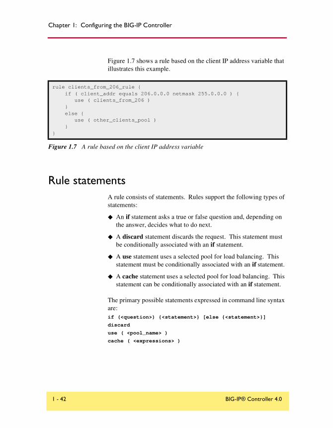
Chapter 1: Configuring the BIG-IP Controller
Figure 1.7 shows a rule based on the client IP address variable that illustrates this example.
Rule statementsA rule consists of statements. Rules support the following types of statements:
◆ An if statement asks a true or false question and, depending on the answer, decides what to do next.
◆ A discard statement discards the request. This statement must be conditionally associated with an if statement.
◆ A use statement uses a selected pool for load balancing. This statement must be conditionally associated with an if statement.
◆ A cache statement uses a selected pool for load balancing. This statement can be conditionally associated with an if statement.
The primary possible statements expressed in command line syntax are:if (<question>) {<statement>} [else {<statement>}]
discard
use ( <pool_name> )
cache ( <expressions> )
rule clients_from_206_rule { if ( client_addr equals 206.0.0.0 netmask 255.0.0.0 ) { use ( clients_from_206 ) } else { use ( other_clients_pool ) }}
Figure 1.7 A rule based on the client IP address variable
1 - 42 BIG-IP® Controller 4.0

Rules
Questions (expressions)
A question or expression is asked by an if statement and has a true or false answer. A question or expression has two parts: a predicate (operator), and one or two subjects (operands).
There are two types of subjects (operands); some subjects change and some subjects stay the same.
• Changing subjects are called variable operands.
• Subjects that stay the same are called constant operands.
A question, or expression, asks questions about variable operands by comparing their current value to constant operands with relational operators.
Constant operands
Possible constant operands are:
◆ IP protocol constants, for example:UDP or TCP
◆ IP addresses expressed in masked dot notation, for example:206.0.0.0 netmask 255.0.0.0
◆ Strings of ASCII characters, for example:"pictures/bigip.gif"
◆ Regular expression strings
Variable operands (variables)
Since variable operands change their value, they need to be referred to by a constant descriptive name. The variables available depend on the context in which the rule containing them is evaluated. Possible variable operands are:
◆ IP packet header variables, such as:
Reference Guide 1 - 43

Chapter 1: Configuring the BIG-IP Controller
• Client request source IP address with the client_addr variable. The client_addr variable is replaced with an unmasked IP address.
• IP protocol, UDP or TCP, with the ip_protocol variable. The ip_protocol variable is replaced with either the UDP or TCP protocol value.
◆ HTTP request strings (see HTTP request string variables on page 1-45). All HTTP request string variables are replaced with string literals.
The evaluation of a rule is triggered by the arrival of a packet. Therefore, variables in the rule may refer to features of the triggering packet. In the case of a rule containing questions about an HTTP request, the rule is evaluated in the context of the triggering TCP SYN packet until the first HTTP request question is encountered. After the proxy, the rule continues evaluation in the context of the HTTP request packet, and variables may refer to this packet. Before a variable is compared to the constant in a relational expression, it is replaced with its current value.
In a rule, relational operators compare two operands to form relational expressions. Possible relational operators and expressions are described in Table 1.9.
Expression Relational Operator
Are two IP addresses equal? <address> equals <address>
Do a string and a regular expression match?
<variable_operand> matches_regex <regular_expression>
Are two strings identical? <string> equals <string>
Is the second string a suffix of the first string?
<variable_operand> ends_with <string>
Table 1.9 The relational operators
1 - 44 BIG-IP® Controller 4.0

Rules
In a rule, logical operators modify an expression or connect two expressions together to form a logical expression. Possible logical operators and expressions are described in Table 1.10.
HTTP request string variables
HTTP request variables are referred to in command line syntax by a predefined set of names. Internally, an HTTP request variable points to a method for extracting the desired string from the current HTTP request header data. Before an HTTP request variable is used in a relational expression, it is replaced with the extracted string. The allowed variable names are:
◆ http_methodThe http_method is the action of the HTTP request. Common values are GET or POST.
Is the second string a prefix of the first string?
<variable_operand> starts_with <string>
Does the first string contain the second string?
<variable_operand> contains <literal_string>
Expression Logical Operator
Is the expression not true? not <expression>
Are both expressions true? <expression> and <expression>
Is either expression true? <expression> or <expression>
Table 1.10 The logical operators
Expression Relational Operator
Table 1.9 The relational operators
Reference Guide 1 - 45

Chapter 1: Configuring the BIG-IP Controller
◆ http_uriThe http_uri is the URL, but does not include the protocol and the fully qualified domain name (FQDN). For example, if the URL is "http://www.url.com/buy.asp", then the URI is "/buy.asp".
◆ http_versionThe http_version is the HTTP protocol version string. Possible values are HTTP/1.0 or HTTP/1.1.
◆ http_hostThe http_host is the value in the Host: header of the HTTP request. It indicates the actual FQDN that the client requested. Possible values are a FQDN or a host IP address in dot notation.
◆ http_cookie <cookie name>The HTTP cookie header is value in the Cookie: for the specified cookie name. An HTTP cookie header line can contain one or more cookie name value pairs. The http_cookie <cookie name> variable evaluates to the value of the cookie with the name <cookie name>. For example, given a request with the following cookie header line:
Cookie: green-cookie=4; blue-cookie=horses
The variable http_cookie blue-cookie evaluates to the string horses. The variable http_cookie green-cookie evaluates to the string 4.
◆ http_header <header_tag_string>The variable http_header evaluates the string following an HTTP header tag that you specify. For example, you can specify the http_host variable with the http_header variable. In a rule specification, if you wanted to load balance based on the host name "andrew" it might look like this:
if ( http_header "Host" starts_with "andrew" ) { use ( andrew_pool ) } else { use ( main_pool ) }
1 - 46 BIG-IP® Controller 4.0
Rules
Configuring rules
You can create rules from the command line or with the Configuration utility. Each of these methods is described in this section.
To add a rule using the Configuration utility
1. In the navigation pane, click Rules.This opens the Rules screen.
2. Click the Add button.The Add Rule screen opens.
3. In the Add Rule screen, fill in the fields to add a rule.You can type in the rule as an unbroken line, or you can use the Enter key to add line breaks. For additional information about configuring rules, click the Help button.
To define a rule from the command line
To define a rule from the command line, use the following syntax:b rule <rule_name> ’ { <if statement> } ’
For more information about the elements of a rule, see Table 1.12, on page 1-49.
Configuring virtual servers that reference rulesYou can define a virtual server that references a rule using the Configuration utility or from the command line.
Note
You must define a pool before you can define a rule that references the pool.
Reference Guide 1 - 47
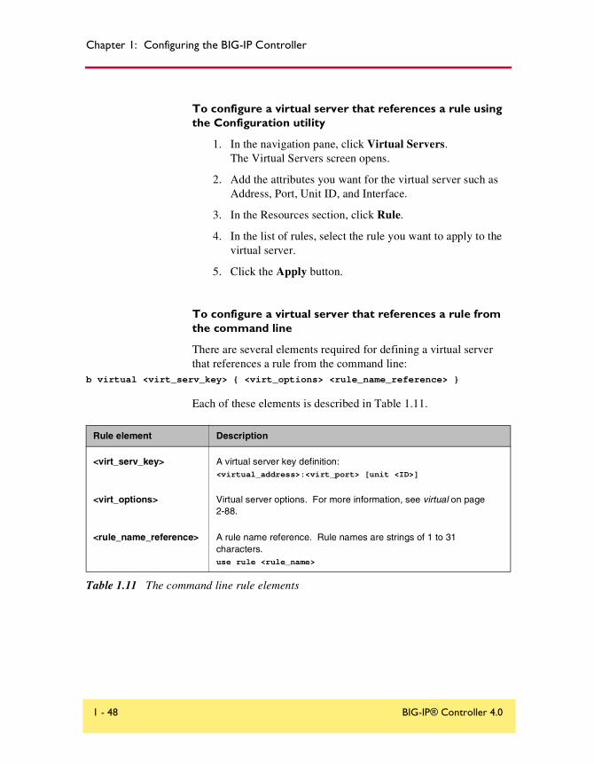
Chapter 1: Configuring the BIG-IP Controller
To configure a virtual server that references a rule using the Configuration utility
1. In the navigation pane, click Virtual Servers.The Virtual Servers screen opens.
2. Add the attributes you want for the virtual server such as Address, Port, Unit ID, and Interface.
3. In the Resources section, click Rule.
4. In the list of rules, select the rule you want to apply to the virtual server.
5. Click the Apply button.
To configure a virtual server that references a rule from the command line
There are several elements required for defining a virtual server that references a rule from the command line:
b virtual <virt_serv_key> { <virt_options> <rule_name_reference> }
Each of these elements is described in Table 1.11.
Rule element Description
<virt_serv_key> A virtual server key definition:<virtual_address>:<virt_port> [unit <ID>]
<virt_options> Virtual server options. For more information, see virtual on page 2-88.
<rule_name_reference> A rule name reference. Rule names are strings of 1 to 31 characters.use rule <rule_name>
Table 1.11 The command line rule elements
1 - 48 BIG-IP® Controller 4.0

Rules
Table 1.12 contains descriptions of all the elements you can use to create rules.
Element Description
rule definitionrule <rule_name { <if_statement> | <cache_statement>}
if statement if ( <expression> ) { <statement> }[ { else <statement> } ] [ { else if <statement> } ]
expression <literal> <variable>( <expression> )exists <variable>not <expression><expression> <binary_operator> <expression>
statement<use_statement><if_statement>discard <cache_statement>
cache statementcache ( <expression> ) { origin_pool <pool_name> cache_pool <pool_name> [ hot_pool <pool_name> ] [ hot_threshold <hit_rate> ] [ cool_threshold <hit_rate> ] [ hit_period <seconds> ][ content_hash_size <sets_in_content_hash> ] }
use statementuse ( <pool_name> )
IP protocol constants UDPTCP
literal<regex_literal> <string_literal><address_literal>
regular expression literal Is a string of 1 to 63 characters enclosed in quotes that may contain regular expressions
string literal Is a string of 1 to 63 characters enclosed in quotes
address literal <dot_notation_longword> [netmask <dot_notation_longword>]
Dot notation longword<0-255>.<0-255>.<0-255>.<0-255>
Table 1.12 The elements you can use to construct rules
Reference Guide 1 - 49

Chapter 1: Configuring the BIG-IP Controller
Cache statement syntaxA cache statement may be either the only statement in a rule or it may be nested within an if statement. The syntax of a cache statement is shown in Figure 1.8.
variablehttp_methodhttp_header <header tag>http_versionhttp_urihttp_hosthttp_cookie <cookie_name>client_addrip_protocol
binary operator orandcontainsmatchesequalsstarts_withends_withmatches_regex
cache ( <expression> ) { origin_pool <pool_name> cache_pool <pool_name> [ hot_pool <pool_name> ] [ hot_threshold <hit_rate> ] [ cool_threshold <hit_rate> ] [ hit_period <seconds> ] [ content_hash_size <sets_in_content_hash> ] }
Figure 1.8 An example of cache statement syntax
Element Description
Table 1.12 The elements you can use to construct rules
1 - 50 BIG-IP® Controller 4.0

Rules
The following table describes the cache statement syntax.
Rule Syntax Description
expression A Boolean expression setting the condition or conditions under which the rule applies.
origin_pool <pool_name> This required attribute specifies a pool of servers with all the content to which requests are load balanced when the requested content is not cacheable or when all the cache servers are unavailable or when you use a BIG-IP Controller to redirect a miss request from a cache.
cache_pool <pool_name> This required attribute specifies a pool of cache servers to which requests are directed to optimize cache performance.
hot_pool <pool_name> This optional attribute specifies a pool of servers that contain content to which requests are load balanced when the requested content is frequently requested (hot). If you specify any of the following attributes in this table, the hot_pool attribute is required.
hot_threshold <hit_rate> This optional attribute specifies the minimum number of requests for content that cause the content to change from cool to hot at the end of the period (hit_period).
cool_threshold <hit_rate> This optional attribute specifies the maximum number of requests for specified content that cause the content to change from hot to cool at the end of the period.
hit_period <seconds> This optional attribute specifies the period in seconds over which to count requests for particular content before deciding whether to change the hot or cool state of the content.
content_hash_size <sets_in_content_hash>
This optional attribute specifies the number subsets into which the content is divided when calculating whether content is hot or cool. The requests for all content in the same subset are summed and a single hot or cool state is assigned to each subset. This attribute should be within the same order of magnitude as the actual number of requests possible. For example, if the entire site is composed of 500,000 pieces of content, a content_hash_size of 100,000 would be typical.
Table 1.13 Description of cache statement syntax
Reference Guide 1 - 51

Chapter 1: Configuring the BIG-IP Controller
A cache statement returns either the origin pool, the hot pool, or the cache pool. When the cache pool is selected, it is accompanied by the indicated node address and port. When a rule returns both a pool and a node, the BIG-IP Controller does not do any additional load balancing or persistence processing.
Figure 1.9 shows an example of a rule containing a cache statement.
Configuring a remote origin server
To ensure that a remote origin server or cache server responds to the BIG-IP Controller rather than to the original cache server that generated the miss request, the BIG-IP Controller also translates the source of the miss request to the translated address and port of the associated SNAT connection.
In order to enable these scenarios, you must:
• Create a SNAT for each cache server.
• Create a SNAT auto-mapping for bounceback.
rule my_rule { if ( http_host starts_with "dogfood" ) { cache ( http_uri ends_with "html" or http_uri ends_with "gif" ) { origin_pool origin_server cache_pool cache_servers hot_pool cache_servers hot_threshold 100 cool_threshold 10 hit_period 60 content_hash_size 1024 } } else { use ( catfood_servers ) }}
Figure 1.9 An example of a cache load balancing rule
1 - 52 BIG-IP® Controller 4.0

Rules
Configuring a SNAT for each origin server
The SNAT translates the address of a packet from the cache server to the address you specify. For more information about SNATs, see SNATs on page 1-90.
To configure a SNAT mapping using the Configuration utility
1. In the navigation pane, click SNATs.The SNATs screen opens.
2. Click the Add button.The Add SNAT screen opens.
3. In the Add SNAT screen, configure the attributes required for the SNAT you want to add. For additional information about configuring a pool, click the Help button.
To configure a SNAT mapping on the command line
The bigpipe snat command defines one SNAT for one or more node addresses. b snat map <orig_ip>... to <snat_ip>
Creating a SNAT automap for bounceback
You must now configure a second SNAT mapping, in this case with the SNAT automap feature, so that when requests are directed to the origin server, the server will reply through the BIG-IP Controller and not directly to the client. (If this were to happen, the next request would then go directly to the origin server, removing the BIG-IP Controller from the loop.)
To configure a SNAT automap from the command line
Configure the existing SNAT address on the external interface as a self address. b self <snat_addr? vlan external snat automap enable
Enable SNAT automap on the external VLAN: b vlan external snat automap enable
Reference Guide 1 - 53

Chapter 1: Configuring the BIG-IP Controller
Additional rule examplesThis section contains additional examples of rules including:
◆ Cookie rule
◆ Language rule
◆ Cache rule
◆ AOL rule
◆ Protocol specific rule
Cookie rule
Figure 1.10 shows a cookie rule that load balances based on the user ID that contains the word VIRTUAL.
if ( exists http_cookie "user-id" and http_cookie "user-id" contains "VIRTUAL" ) { use ( virtual_pool )}else { use ( other_pool )}
Figure 1.10 Cookie rule example
1 - 54 BIG-IP® Controller 4.0

Rules
Language rule
Figure 1.11 shows a rule that load balances based on the language requested by the browser.
Cache rule
Figure 1.12 shows an example of a rule that you can use to send cache content, such as .gifs, to a specific pool.
if ( exists http_header "Accept-Language" ) { if ( http_header "Accept-Language" equals "fr" ) { use ( french_pool ) } else if ( http_header "Accept-Language" equals "sp" ) { use (spanish_pool ) } else { use ( english_pool )}
Figure 1.11 Sample rule that load balances based on the language requested by the browser
if ( http_uri ends_with "gif" or http_uri ends_with "html" ) { use ( cache_pool )}else { use ( server_pool )}
Figure 1.12 An example of a cache rule
Reference Guide 1 - 55
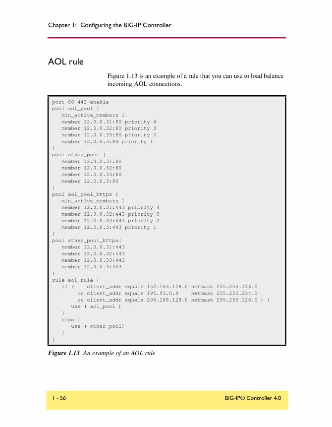
Chapter 1: Configuring the BIG-IP Controller
AOL rule
Figure 1.13 is an example of a rule that you can use to load balance incoming AOL connections.
port 80 443 enablepool aol_pool { min_active_members 1 member 12.0.0.31:80 priority 4 member 12.0.0.32:80 priority 3 member 12.0.0.33:80 priority 2 member 12.0.0.3:80 priority 1}pool other_pool { member 12.0.0.31:80 member 12.0.0.32:80 member 12.0.0.33:80 member 12.0.0.3:80 }pool aol_pool_https { min_active_members 1 member 12.0.0.31:443 priority 4 member 12.0.0.32:443 priority 3 member 12.0.0.33:443 priority 2 member 12.0.0.3:443 priority 1}pool other_pool_https{ member 12.0.0.31:443 member 12.0.0.32:443 member 12.0.0.33:443 member 12.0.0.3:443}rule aol_rule { if ( client_addr equals 152.163.128.0 netmask 255.255.128.0 or client_addr equals 195.93.0.0 netmask 255.255.254.0 or client_addr equals 205.188.128.0 netmask 255.255.128.0 ) { use ( aol_pool ) } else { use ( other_pool) }}
Figure 1.13 An example of an AOL rule
1 - 56 BIG-IP® Controller 4.0

Rules
IP protocol specific ruleFigure 1.14 shows a rule that you can use to send TCP DNS to the pool tcp_pool and UDP DNS to the pool udp_pool.
rule aol_rule_https { if ( client_addr equals 152.163.128.0 netmask 255.255.128.0 or client_addr equals 195.93.0.0 netmask 255.255.254.0 or client_addr equals 205.188.128.0 netmask 255.255.128.0 ) { use ( aol_pool_https ) } else { use ( other_pool_https) }}virtual 15.0.140.1:80 { use rule aol_rule }virtual 15.0.140.1:443 { use rule aol_rule_https special ssl 30 }
Figure 1.13 An example of an AOL rule
rule myrule { if ( ip_protocol equals UDP ) { use ( udp_pool ) } else { use ( tcp_pool ) }
Figure 1.14 An example of an IP protocol rule
Reference Guide 1 - 57

Chapter 1: Configuring the BIG-IP Controller
Virtual serversVirtual servers provide the ability to map a number of network devices to a single virtual address. A virtual server in combination with a load balancing pool, or rule, provides the ability to load balance connections, use persistence, and also provide high availability features on the BIG-IP Controller.
You must configure a pool of servers before you can create a virtual server that references the pool. Before you configure virtual servers, you need to know:
• If standard virtual servers or wildcard virtual servers meet the needs of your network
• Whether you need to activate optional virtual server properties
Once you know which virtual server options are useful in your network, you can define two types of servers:
• virtual servers
• wildcard virtual servers
The attributes you can configure for a virtual server are in Table 1.14.
Attributes Description
Standard virtual server
A standard virtual server sends connection requests to load balancing pools or rules.
Wildcard virtual server
A wildcard virtual server is typically used to make requests to hosts on the Internet from a network behind the BIG-IP Controller.
Network virtual server
A network virtual server handles a whole range of addresses in a network.
Other virtual server attributes
You can set connection limits, translation properties, last hop pools, and mirroring information for virtual servers.
Table 1.14 The attributes you can configure for a virtual server
1 - 58 BIG-IP® Controller 4.0

Virtual servers
Using standard or wildcard virtual serversVirtual servers reference a pool you create that contains a group of content servers, firewalls, routers, or cache servers, and they are associated with one or more external interfaces on the BIG-IP Controller.
You can configure two different types of virtual servers:
◆ Standard virtual serversA standard virtual server represents a site, such as a web site or an FTP site, and it provides load balancing for a pool of content servers or other network devices. The virtual server IP address should be the same IP address that you register with DNS for the site that the virtual server represents.
◆ Wildcard virtual serversA wildcard virtual server load balances a pool of transparent network devices such as firewalls, routers, or cache servers. Wildcard virtual servers are configured with an IP address of 0.0.0.0, and sometimes with a virtual port of 0.
Note that both the Configuration utility and the bigpipe utility accept host names in place of IP addresses, and also accept standard service names in place of port numbers.
Defining virtual servers
A standard virtual server represents a specific site, such as an Internet web site or an FTP site, and it load balances content servers that are members of a pool. The IP address that you use for a standard virtual server should match the IP address that DNS associates with the site’s domain name.
Note
If you are using a 3-DNS Controller in conjunction with the BIG-IP Controller, the 3-DNS Controller uses the IP address associated with the registered domain name in its own configuration. For details, refer to the 3-DNS Administrator Guide.
Reference Guide 1 - 59

Chapter 1: Configuring the BIG-IP Controller
To define a standard virtual server using the Configuration utility
1. In the navigation pane, click Virtual Servers.
2. Click the Add button.The Add Virtual Server screen opens.
3. In the Address box, enter the virtual server's IP address or host name.
4. In the Port box, either type a port number, or select a service name from the drop-down list.
5. In the Select Physical Resources screen, click the Pool button.If you want to assign a load balancing rule to the virtual server, click Rule and select a rule you have configured.
6. In the Pool list, select the pool you want to apply to the virtual server.
7. Click the Apply button.
To define a standard virtual server mapping from the command line
Type the bigpipe virtual command as shown below. Also, remember that you can use host names in place of IP addresses, and that you can use standard service names in place of port numbers.b virtual <virt_ip>:<service> use pool <pool_name>
b virtual <virt_ip>:<service> use rule <rule_name>
For example, the following command defines a virtual server that maps to the pool my_pool:b virtual 192.200.100.25:80 use pool my_pool
Defining wildcard virtual servers
Wildcard virtual servers are a special type of virtual server designed to manage network traffic for transparent network devices, such as transparent firewalls, routers, proxy servers, or
1 - 60 BIG-IP® Controller 4.0

Virtual servers
cache servers. A wildcard virtual server manages network traffic that has a destination IP address unknown to the BIG-IP Controller. A standard virtual server typically represents a specific site, such as an Internet web site, and its IP address matches the IP address that DNS associates with the site’s domain name. When the BIG-IP Controller receives a connection request for that site, the BIG-IP Controller recognizes that the client’s destination IP address matches the IP address of the virtual server, and it subsequently forwards the client to one of the content servers that the virtual server load balances.
However, when you are load balancing transparent nodes, a client’s destination IP address is going to seem random. The client is connecting to an IP address on the other side of the firewall, router, or proxy server. In this situation, the BIG-IP Controller cannot match the client’s destination IP address to a virtual server IP address. Wildcard virtual servers resolve this problem by not translating the incoming IP address at the virtual server level on the BIG-IP Controller. For example, when the BIG-IP Controller does not find a specific virtual server match for a client’s destination IP address, it matches the client’s IP address to a wildcard virtual server. The BIG-IP Controller then forwards the client’s packet to one of the firewalls or routers that the wildcard virtual server load balances, which in turn forwards the client’s packet to the actual destination IP address.
A note about wildcard ports
When you configure wildcard virtual servers and the nodes that they load balance, you can use a wildcard port (port 0) in place of a real port number or service name. A wildcard port handles any and all types of network services.
A wildcard virtual server that uses port 0 is referred to as a default wildcard virtual server, and it handles traffic for all services. A port-specific wildcard virtual server handles traffic only for a particular service, and you define it using a service name or a port number. If you use both a default wildcard virtual server and port-specific wildcard virtual servers, any traffic that does not
Reference Guide 1 - 61

Chapter 1: Configuring the BIG-IP Controller
match either a standard virtual server or one of the port-specific wildcard virtual servers is handled by the default wildcard virtual server.
You can use port-specific wildcard virtual servers for tracking statistics for a particular type of network traffic, or for routing outgoing traffic, such as HTTP traffic, directly to a cache server rather than a firewall or router.
We recommend that when you define transparent nodes that need to handle more than one type of service, such as a firewall or a router, you specify an actual port for the node and turn off port translation for the virtual server.
Defining the wildcard virtual server mappings
There are two procedures required to set up a wildcard virtual server. First, you must define the wildcard virtual server. Then you must turn port translation off for the virtual server.
To define a wildcard virtual server using the Configuration utility
1. In the navigation pane, click Virtual Servers.
2. Click the Add button.The Add Virtual Server screen opens.
3. In the Address box, type the wildcard IP address 0.0.0.0.
4. In the Port box, type a port number, or select a service name from the drop-down list. Note that port 0 defines a wildcard virtual server that handles all types of services. If you specify a port number, you create a port-specific wildcard virtual server. The wildcard virtual server only handles traffic for the port specified.
5. In Resources, click the Pool button.
6. In the Pool list, select the pool you want to apply to the virtual server.
7. Click the Apply button.
1 - 62 BIG-IP® Controller 4.0

Virtual servers
To turn off port translation for a wildcard virtual server using the Configuration utility
After you define the wildcard virtual server with a wildcard port, you must disable port translation for the virtual server.
1. In the navigation pane, click Virtual Servers.The Virtual Servers screen opens.
2. In the virtual server list, click the virtual server for which you want to turn off port translation.The Virtual Server Properties screen opens.
3. In the Enable Translation section, clear the Port box.
4. Click the Apply button.
To define a wildcard virtual server mapping from the command line
There are three commands required to set up a wildcard virtual server. First, you must define a pool that contains the addresses of the transparent devices. Next, you must define the wildcard virtual server. Then you must turn port translation off for the virtual server. To define the pool of transparent devices, use the bigpipe pool command. For example, you can create a pool of transparent devices called transparent_pool that uses the Round Robin load balancing mode:
b pool transparent_pool { member <member_definition>... member <member_definition> }
To define the virtual server, use the bigpipe virtual command:b virtual <virt_ip>:<service> use pool <pool_name>
After you define the virtual server, you can enable or disable port translation using the following command:
b virtual <virt_ip>:<service> translate port enable | disable
For example, you can create a pool of transparent devices called transparent_pool:
b pool transparent_pool { member 10.10.10.101:80 member 10.10.10.102:80 member 10.10.10.103:80 }
Reference Guide 1 - 63

Chapter 1: Configuring the BIG-IP Controller
After you create the pool of transparent nodes, use the following command to create a wildcard virtual server that maps to the pool transparent_pool. Because the members are firewalls and need to handle a variety of services, the virtual server is defined using port 0 (or * or any). You can specify any valid non-zero port for the node port and then turn off port translation for that port. In this example, service checks ping port 80.
b virtual 0.0.0.0:0 use pool transparent_pool
After you define the virtual server, turn off port translation for the port in the virtual server definition. In this example, port 80 is used for service checking. If you do not turn off port translation, all incoming traffic would be translated to port 80.
b virtual 0.0.0.0:0 translate port disable
Configuring a network virtual serverYou can configure a network virtual server to handle a whole network range, instead of just one IP address, or all IP addresses (wildcard virtual servers). For example, the virtual server in Figure 1.15 handles all traffic addresses in the 192.168.1.0 network.
A network virtual server is a virtual server that has no bits set in the host portion of the IP address. In other words, the host portion is zero. You must specify a network mask to indicate which portion of the address is the network address and which portion is the host address. In the previous example, since the network mask is 255.255.255.0, the network portion of the address is 192.168.1 and the host portion is .0. The previous example would direct all traffic destined to the subnet 192.168.1.0/24 through the BIG-IP Controller to the ingress_firewalls pool.
bigpipe virtual 192.168.1.0:0 { netmask 255.255.255.0 broadcast 192.168.1.255 use pool ingress_firewalls}
Figure 1.15 A sample network virtual server
1 - 64 BIG-IP® Controller 4.0

Virtual servers
Another way you can use this feature is to create a catch-all web server for an entire subnet. For example, you could create the following network virtual server (Figure 1.16).
This configuration directs a web connection destined to any address within the subnet 192.168.1.0/24 to the default_webservers pool.
Mirroring virtual server stateMirroring provides seamless recovery for current connections, persistence information, SSL persistence, or sticky persistence when a BIG-IP Controller fails. When you use the mirroring feature, the standby controller maintains the same state information as the active controller. Transactions such as FTP file transfers continue as though uninterrupted.
Note
Mirroring slows BIG-IP Controller performance and is primarily for long-lived services like FTP and Telnet. Mirroring is not useful for short-lived connections like HTTP.
Since mirroring is not intended to be used for all connections and persistence, it must be specifically enabled for each virtual server.
To control mirroring for a virtual server, use the bigpipe virtual mirror command to enable or disable mirroring of persistence information, or connections, or both. The syntax of the command is:
b virtual <virt addr>:<service> mirror [ persist | conn ] \ enable | disable
bigpipe virtual 192.168.1.0:http { netmask 255.255.255.0 broadcast 192.168.1.255 use pool default_webservers}
Figure 1.16 A catch-all web server configuration.
Reference Guide 1 - 65

Chapter 1: Configuring the BIG-IP Controller
Use persist to mirror persistence information for the virtual server. Use conn to mirror connection information for the virtual server. To display the current mirroring setting for a virtual server, use the following syntax:
b virtual <virt addr>:<service> mirror [ persist | conn ] show
If you do not specify either persist, for persistent information, or conn, for connection information, the BIG-IP Controller assumes that you want to display both types of information.
Note
If you set up mirroring on a virtual server that supports FTP connections, you need to mirror the control port virtual server, and the data port virtual server.
The following example shows the two commands used to enable mirroring for virtual server v1 on the FTP control and data ports:b virtual v1:21 mirror conn enable
b virtual v1:20 mirror conn enable
Additional virtual server optionsThis section contains information on the following features you can use to manage virtual servers:
• Display information about a virtual server
• Set a netmask and broadcast
• Set a connection limit
• Set translation properties for virtual addresses and ports
• Set up a last hop pool for a virtual server
• Enable or disable a virtual address
• Display information about a virtual address
• Delete a virtual server
• Reset statistics for a virtual server
1 - 66 BIG-IP® Controller 4.0

Virtual servers
• Set software acceleration properties for virtual server with IPFW turned on
To display information about virtual servers
Use the following syntax to display information about all virtual servers included in the configuration:b virtual show
Use the following syntax to display information about one or more virtual servers included in the configuration:
b virtual <virt_ip>:<service> [...<virt_ip>:<service>] show
The command displays information such as the nodes associated with each virtual server, the nodes’ status, and the current, total, and maximum number of connections managed by the virtual server since the BIG-IP Controller was last rebooted.
To set a user-defined netmask and broadcast
The default netmask for a virtual address, and for each virtual server hosted by that virtual address, is determined by the network class of the IP address entered for the virtual server. The default broadcast is automatically determined by the BIG-IP Controller, and it is based on the virtual address and the current netmask. You can override the default netmask and broadcast for a network virtual address only.
All virtual servers hosted by the virtual address use the netmask and broadcast of the virtual address, whether they are default values or they are user-defined values.
If you want to use a custom netmask and broadcast, you define both when you define the network virtual server:
b virtual <virt_ip>[:<service>] [vlan <vlan_name> disable | enable] [netmask <ip>] [broadcast <ip>] use pool <pool_name>
Note
The BIG-IP Controller calculates the broadcast based on the IP address and the netmask. In most cases, a user-defined broadcast address is not necessary.
Reference Guide 1 - 67
Chapter 1: Configuring the BIG-IP Controller
Again, even when you define a custom netmask and broadcast in a specific network virtual server definition, the settings apply to all virtual servers that use the same virtual address. The following sample command shows a user-defined netmask and broadcast:
b virtual www.SiteOne.com:http netmask 255.255.0.0 broadcast 10.0.140.255 use pool my_pool
The /bitmask option shown in the following example applies network and broadcast address masks. In this example, a 24-bit bitmask sets the network mask and broadcast address for the virtual server: b virtual 206.168.225.0:80/24 use pool my_pool
You can generate the same broadcast address by applying the 255.255.255.0 netmask. The effect of the bitmask is the same as applying the 255.255.255.0 netmask. The broadcast address is derived as 206.168.225.255 from the network mask for this virtual server.
To set a connection limit
The default setting is to have no limit to the number of concurrent connections allowed on a virtual server. You can set a concurrent connection limit on one or more virtual servers using the following command:
b virtual <virt_ip>[:<service>] [...<virt_ip>[:<service>] ] limit <max conn>
The following example shows two virtual servers set to have a concurrent connection limit of 5000 each:
b virtual www.SiteOne.com:http www.SiteTwo.com:ssl limit 5000
To turn the limit off, set the <max conn> variable to zero:b virtual <virt_ip>[:<service>] [...<virt_ip>[:<service>] ] limit 0
To set translation properties for virtual addresses and ports
Turning off port translation for a virtual server is useful if you want to use the virtual server to load balance connections to any service. Use the following syntax to enable or disable port translation for a virtual server:
1 - 68 BIG-IP® Controller 4.0

Virtual servers
b virtual <virt_ip>:<service> translate port enable | disable | show
You can also configure the translation properties for a virtual server address. This option is useful when the BIG-IP Controller is load balancing devices which have the same IP address. This is typical with the nPath routing configuration where duplicate IP addresses are configured on the loopback device of several servers. Use the following syntax to enable or disable address translation for a virtual server:
b virtual <virt_ip>:<service> translate addr enable | disable | show
To set up last hop pools for virtual servers
In cases where you have more than one router sending connections to a BIG-IP Controller, connections are automatically sent back through the same router from which they were received when the auto_lasthop global variable is enabled, as it is by default. If the global auto_lasthop is disabled for any reason (for example, you may not want it for an SSL gateway), you can direct your replies to the same router using a last hop pool
To configure a last hop pool, you must first create a pool containing the router inside addresses. After you create the pool, use the following syntax to configure a last hop pool for a virtual server:
b virtual <virt_ip>:<service> lasthop pool <pool_name> | none | show
To enable or disable a virtual server
You can remove an existing virtual server from network service, or return the virtual server to service, using the disable and enable keywords. When you disable a virtual server, the virtual server no longer accepts new connection requests, but it allows current connections to finish processing before the virtual server goes down.
Use the following syntax to remove a virtual server from network service:
b virtual <virt_ip>:<service> [...<virt_ip>:<service>] disable
Use the following syntax to return a virtual server to network service:b virtual <virt_ip>:<service> enable
Reference Guide 1 - 69
Chapter 1: Configuring the BIG-IP Controller
To enable or disable a virtual address
You can remove an existing virtual address from network service, or return the virtual address to service, using the disable and enable keywords. Note that when you enable or disable a virtual address, you inherently enable or disable all of the virtual servers that use the virtual address.b virtual <virt_ip> disable
Use the following syntax to return a virtual address to network service:b virtual <virt_ip> enable
To display information about virtual addresses
You can also display information about the virtual addresses that host individual virtual servers. Use the following syntax to display information about one or more virtual addresses included in the configuration:b virtual <virt_ip> [... <virt_ip> ] show
The command displays information such as the virtual servers associated with each virtual address, the status, and the current, total, and maximum number of connections managed by the virtual address since the BIG-IP Controller was last rebooted, or since the BIG-IP Controller became the active unit (redundant configurations only).
To delete a virtual server
Use the following syntax to permanently delete one or more virtual servers from the BIG-IP Controller configuration:
b virtual <virt_ip>:<service> [... <virt_ip>:<service>] delete
To reset statistics for a virtual server
Use the following command to reset the statistics for an individual virtual server:b virtual [<virt_ip:port>] stats reset
1 - 70 BIG-IP® Controller 4.0

Virtual servers
Turning software acceleration off for virtual servers using IPFW rate filters
Additional enhancements are included in this release that speed packet flow for TCP connections when the packets are not fragmented. In most configurations these software enhancements are automatically turned on and do not require any additional configuration.
However, you may want to turn off these enhancements for individual virtual servers that use IPFW rate filters. With the speed enhancements on, IPFW only examines the first SYN packet in any given connection. If want to filter all packets, you should turn the speed enhancements off. To do this, you must first set the global state of the system on, and then you must turn the feature off for individual virtual servers that use IPFW rate filtering. You can change the settings for these enhancements from the command line or in the Configuration utility.
To set software acceleration controls from the command line
Before you can turn off software acceleration for a virtual server, you must set the bigpipe global variable fastflow_active to on with the following command:b global fastflow_active on
After you set the global variable, use the following bigpipe commands to disable software acceleration for existing virtual servers that use IPFW rate filtering:b virtual <ip>:<service> accelerate disable
For example, if you want to turn acceleration off for the virtual server 10.10.10.50:80, type the following command:b virtual 10.10.10.50:80 accelerate disable
You can define a virtual server with acceleration disabled using the following syntax:
b virtual <ip>:<service> use pool the_pool accelerate disable
For example, if you want to define the virtual server 10.10.10.50:80 with the pool IPFW_pool and acceleration turned off, type the following command:
Reference Guide 1 - 71

Chapter 1: Configuring the BIG-IP Controller
b virtual 10.10.10.50:80 use pool IPFW_pool accelerate disable
Using additional BIG-IP Controller features with virtual serversAfter you create a pool and define a virtual server that references the pool, you can set up additional features, such as network address translation (NAT) or extended content verification (ECV). For details on Network address translations, see NATs on page 1-87. For details on persistence for connections that should return to the node to which they last connected, see Setting up persistence for a pool on page 1-22.
1 - 72 BIG-IP® Controller 4.0

Proxies
ProxiesUse the proxy command to create, delete, modify, or display the SSL or content converter gateway definitions on the BIG-IP Controller. For detailed information about setting up the SSL Accelerator feature, see the BIG-IP Administrator Guide, Chapter 8, Configuring an SSL Accelerator. For detailed information about setting up the content converter feature, see the BIG-IP Administrator Guide, Chapter 13, Configuring a Content Converter.
To create an SSL gateway from the command line
Use the following command syntax to create an SSL gateway:b proxy <ip>:<service> [unit <unit_id>] [vlans <vlan_name> disable |
enable] [<unit id>] target <server | virtual> <ip>:<service> ssl enable key <key> cert <cert>
For example, from the command line you can create an SSL gateway that looks like this:
b proxy 10.1.1.1:443 unit 1 target virtual 20.1.1.1:80 ssl enable key my.server.net.key cert my.server.net.crt }
Note that when the configuration is written out in the bigip.conf file, the line ssl enable is automatically added. When the SSL gateway is written in the /config/bigip.conf file, it looks like the sample in Figure 1.17.
proxy 10.1.1.1:443 3.1 unit 1 { netmask 255.255.255.0 broadcast 10.1.1.255 target virtual 20.1.1.1:80 ssl enable key my.server.net.key cert my.server.net.crt}
Figure 1.17 An example SSL gateway configuration
Reference Guide 1 - 73

Chapter 1: Configuring the BIG-IP Controller
Creating a content converter gateway from the command line
Configuring a content converter consists of two steps. First, configure the Akamai on-the-fly conversion software for your network. Second, create the content converter gateway using the proxy command. (If the software is not configured first, the attempt to create a proxy will fail.)
To configure the on-the-fly conversion software
1. On the BIG-IP Controller, bring up the Akamai configuration file /etc/config/akamai.conf in an editor like vi or pico.
2. Under the heading [CpCode] you will find the text default=XXXXX. Replace the Xs with the CP code provided by your Akamai Integration Consultant. (If contacting your consultant, specify that you are using the BIG-IP on-the-fly Akamaizer based on Akamai's 1.0 source code.) Example:
default=773
3. Under the heading [Serial Number] you will find the text staticSerialNumber=XXXXX. Replace the Xs with the static serial number provided by your Akamai Integration Consultant. Example:
staticSerialNumber=1025
Note: This value needs to be set only if the algorithm under [Serial Number] is set to static, as it is in the default file. If you choose to set the algorithm to deterministicHash or deterministicHashBounded, the static serial number is not applicable. If you are unsure what method to select, contact your Akamai Integration Consultant.
4. Under the heading [URLMetaData] you will find the text httpGetDomains=XXXXX. Replace the X’s with domain name of the content to be converted. Example:
httpGetDomains=www.f5.com
5. Save and exit the file.
1 - 74 BIG-IP® Controller 4.0

Proxies
To configure the content converter gateway
Use the following command syntax to create an content converter gateway:
b proxy <ip>:<service> [unit <unit_id>] target server | virtual <ip>:<service> akamaize enable
For example, from the command line you can create a gateway that looks like this:
b proxy 10.1.1.1:80 unit 1 target virtual 20.1.1.1:80 akamaize enable
Note that when the configuration is written out in the bigip.conf file, the line akamaize enable is automatically added. When the content converter gateway is written in the /config/bigip.conf file, it looks like the sample in Figure 1.18.
To enable, disable, or delete a gateway from the command line
You can enable, disable, or delete a gateway with the following syntax:b proxy <ip>:<service> enable
b proxy <ip>:<service> disable
b proxy <ip>:<service> delete
If you want to enable the gateway 209.100.19.22:443, you might type the following command:b proxy 209.100.19.22:443 enable
If you want to disable the gateway 209.100.19.22:443, you could type the following command:b proxy 209.100.19.22:443 disable
proxy 10.1.1.1:80 unit 1 { netmask 255.255.255.0 broadcast 10.1.1.255 target virtual 20.1.1.1:80 akamaize enable }
Figure 1.18 An example content converter gateway configuration
Reference Guide 1 - 75

Chapter 1: Configuring the BIG-IP Controller
For example, if you want to delete the SSL gateway 209.100.19.22:443, type the following command:b proxy 209.100.19.22:443 delete
Disabling VLANs for a gateway
A gateway is mapped by default to all VLANs on the internal and external networks of the BIG-IP Controller. You must disable any VLANs to which you do not want the gateway mapped using the bigpipe proxy vlans <vlan_list> disable syntax:b proxy vlans <vlan_name> disable
To display configuration information for a gateway from the command line
Use the following syntax to view the configuration for the specified gateway:b proxy <ip>:<service> show
For example, if you want to view configuration information for the SSL gateway 209.100.19.22:80, type the following command:b proxy 209.100.19.22:80 show
1 - 76 BIG-IP® Controller 4.0

Proxies
Figure 1.19 is a sample output from the bigpipe proxy show command.
PROXY +---> 11.12.1.200:443 -- Originating Address -- Enabled Unit 1 | Key File Name balvenie.scotch.net.key | Cert File Name balvenie.scotch.net.crt | LastHop Pool Name | SSL Encryption: enabled | Akamiaize Content: disabled +===> 11.12.1.111:80 -- Destination Address -- server
PROXY +---> 11.12.1.120:443 -- Originating Address -- Enabled Unit 1 | Key File Name balvenie.scotch.net.key | Cert File Name balvenie.scotch.net.crt | LastHop Pool Name | SSL Encryption: enabled | Akamiaize Content: disabled +===> 11.12.1.111:80 -- Destination Address -- virtual
Figure 1.19 Output from the bigpipe proxy show command
Reference Guide 1 - 77

Chapter 1: Configuring the BIG-IP Controller
NodesNodes are the network devices to which the BIG-IP Controller passes traffic. A node can be referenced by a load balancing pool. You can display information about nodes and set properties for nodes.
The attributes you can configure for a node are in Table 1.15.
Table 1.15 The attributes you can configure for a node.
To enable and disable nodes and node addresses
A node must be enabled in order to accept traffic. When a node is disabled, it allows existing connections to time out and accept new connections only if they belong to an existing session. (In this way a disabled node differs from a node that is set down. The down node allows existing connections to time out, but accepts no new connections.)
To enable a node or node address, use the node command with the enable option:b node 192.168.21.1 enable
To disable a node or node address, use the node command with the disable option:
Node Attributes Description
Enable/Disable nodes
You can enable or disable nodes independently from a load balancing pool.
Set node up/down You can set a node up or down.
Connection limit You can place a connection limit on a node.
Associate a node with a monitor
You can associate a health monitor with a node, creating an instance of that monitor.
Add a node as a member of a pool
You can add a node to a pool as a member. This allows you to use the load balancing and persistence methods defined in the pool to control connections handled by the node.
Fallback host You can specify a fallback host for http redirect.
1 - 78 BIG-IP® Controller 4.0

Nodes
b node 192.168.21.1 disable
To enable one or more nodes or node addresses, use the node command with and the enable option:b node 192.168.21.1:80 enable
To disable one or more node or node addresses, use the node command with disable option: b node 192.168.21.1:80 disable
To mark nodes and node ports up or down
A node must be marked up in order to accept traffic. When a node is marked down it allows existing connections to time out but accepts no new connections.
To mark a node down, use the node command with a node and the down option. (Note that marking a node down prevents the node from accepting new connections. Existing connections are allowed to complete.)b node 192.168.21.1 down
To mark a node up, use the node command with the up option: b node 192.168.21.1 up
To mark a particular service down, use the node command with a node and port, and the down option. (Note that marking a port down prevents the port from accepting new connections. Existing connections are allowed to complete.)b node 192.168.21.1:80 down
To mark a particular port up, use the node command with up option: b node 192.168.21.1:80 up
To set connection limits for nodes
Use the following command to set the maximum number of concurrent connections allowed on a node:
b node <node_ip>[:<service>][...<node_ip>[:<service>]] \limit <max conn>
Note that to remove a connection limit, you also issue the preceding command, but set the <max conn> variable to 0 (zero). For example:
Reference Guide 1 - 79

Chapter 1: Configuring the BIG-IP Controller
b node 192.168.21.1:80 limit 0
To set connection limits for nodes
The following example shows how to set the maximum number of concurrent connections to 100 for a list of nodes:b node 192.168.21.1 192.168.21.1 192.168.21.1 limit 100
To remove a connection limit, you also issue this command, but set the <max conn> variable to 0 (zero).
To associate a health monitor with a node
Use the following command to associate a health monitor with a node:node <node> monitor use <monitor>
A monitor can be placed on multiple nodes and a node can have multiple monitors placed on it. To place a monitor on multiple nodes:node <node_list> monitor use <monitor>
To place multiple monitors on a node:node <node> monitor use <monitor1> and <monitor2>...
For more information on using the node command with health monitors, refer to Health monitors on page 1-120.
To display status of all nodes
When you issue the node show command, the BIG-IP Controller displays the node status (up or down, or unchecked), and a node summary of connection statistics, which is further broken down to show statistics by port. b node show
The report shows the following information:
❖ current number of connections
❖ total number of connections made to the node since last boot
❖ maximum number of concurrent connections since the last boot
❖ concurrent connection limit on the node
❖ the total number of connections made to the node since last boot
1 - 80 BIG-IP® Controller 4.0

Nodes
❖ total number of inbound and outbound packets and bits
Figure 1.20 shows the output of this command.
To display the status of individual nodes and node addresses
Use the following command to display status and statistical information for one or more node addresses:b node 192.168.21.1 show
The command reads the status of each node address, the number of current connections, total connections, and connections allowed, and the number of cumulative packets and bits sent and received.
Use the following command to display status and statistical information for one or more specific nodes:b node 192.168.21.1:80 show
To reset statistics for a node
Use the following command to reset the statistics for an individual node address:b node [<node_ip>:<service>] stats reset
To add a node as a member to a pool
You can add a node as a member to a load balancing pool. For detailed information about how to do this, see Proxies on page 1-73.
bigpipe node 192.168.200.50:20NODE 192.168.200.50 UP | (cur, max, limit, tot) = (0, 0, 0, 0)| (pckts,bits) in = (0, 0), out = (0, 0)+- PORT 20 UP (cur, max, limit, tot) = (0, 0, 0, 0) (pckts,bits) in = (0, 0), out = (0, 0)
Figure 1.20 Node status and statistics
Reference Guide 1 - 81

Chapter 1: Configuring the BIG-IP Controller
ServicesEnables and disables network traffic on services, and also sets connection limits and timeouts. You can use port numbers or service names (for example, www, http, or 80) for the <service> parameter. Note that the settings you define with this command control the service for all virtual servers that use it. By default, all services are disabled.
A service is any valid port number, between 0 and 65535, inclusive, or any valid service name in the /etc/services file.
Tip
Virtual servers using the same service actually share a port on the BIG-IP Controller. This command is global, you only need to open access to a port once; you do not need to open access to a port for each instance of a virtual server that uses it.
The attributes you can configure for a port are shown in Table 1.16
Table 1.16 The attributes you can configure for a service.
To allow access to services in the Configuration utility
Any time you create a virtual server and define a port or service with the Configuration utility, the port or service is automatically enabled.
Attributes Description
Allow access to services
As a security measure, all services are locked down on the BIG-IP Controller. In order for the BIG-IP Controller to load balance traffic, you must enable access to the service on which the BIG-IP Controller will receive traffic.
Connection limits You can define a connection limit for a service so that a flood of connections does not overload the BIG-IP Controller.
Set idle connection timeouts
You can set the idle connection timeout to close idle connections.
1 - 82 BIG-IP® Controller 4.0

Services
To allow access to services on the command line
Using the bigpipe port command, you can allow access to one or more ports at a time.b port <port>... <port> enable
For example, in order to enable HTTP (port 80) and Telnet (port 23) services, you can enter the following bigpipe port command:b port 80 23 443 enable
To set connection limits on services
Use the following syntax to set the maximum number of concurrent connections allowed on a service. Note that you can configure this setting for one or more services.b service <service> [...<service>] limit <max conn>
To turn off a connection limit for one or more services, use the same command, setting the <max conn> parameter to 0 (zero) like this:b service <service> [...<service>] limit 0
To enable or disable TCP for services
You can enable or disable TCP for specific services. The default setting for all services is enabled. Use the following syntax to disable TCP for one or more services:b service <service> [...<service>] tcp disable
To re-enable TCP, use this syntax:b service <service> [...<service>] tcp enable
To enable or disable UDP for services
You can enable or disable UDP for specific services. The default setting for all services is disabled. Use the following syntax to enable UDP for one or more services:b service <service> [...<service>] udp enable
To disable UDP, use this syntax:b service <service> [...<service>] udp disable
Reference Guide 1 - 83

Chapter 1: Configuring the BIG-IP Controller
To set the idle connection timeout for TCP traffic
To set the TCP timeout on one or more services, where the <seconds> parameter is the number of seconds before an idle connection is dropped, use the following syntax:b service <service> [<service>...] timeout tcp <seconds>
For example, the following command sets the TCP timeout to 300 seconds for port 53:b service 53 timeout tcp 300
To turn off TCP timeout for a service, use the above command, setting the <seconds> parameter to zero:b service 53 timeout tcp 0
To set the idle connection timeout for UDP traffic
To set the UDP timeout on one or more services, where the <seconds> parameter is the number of seconds before an idle connection is dropped, use the following syntax:b service <service> [<service>...] timeout udp <seconds>
For example, the following command sets the UDP timeout to 300 seconds for port 53:b service 53 timeout udp 300
To turn off UDP timeout for a service, use the above command, setting the <seconds> parameter to zero:b service 53 timeout udp 0
To display service settings
Use the following command to display the settings for all services:b service show
Use the following syntax to display the settings for a specific service of services:b service <service> [...<service>] show
The system displays the output shown in Figure 1.21.
1 - 84 BIG-IP® Controller 4.0

Services
Figure 1.22 shows a sample of formatted output of the port command.
SERVICE 80 http tcp enabled timeout 1005 udp disabled timeout 60 (cur, max, limit, tot, reaped) = (0, 0, 0, 0, 0)
(pckts,bits) in = (0, 0), out = (0, 0)
Figure 1.21 Sample output of the service show command
bigpipe port telnet show
PORT 23 telnet enable(cur, max, limit, tot, reaped) = (37,73,100,691,29)
(pckts,bits) in = (2541, 2515600), out = (2331, 2731687)
Figure 1.22 Formatted output of port command showing the Telnet port statistics
Reference Guide 1 - 85

Chapter 1: Configuring the BIG-IP Controller
Address translation & forwardingAddress translation and forwarding are used in various ways on the BIG-IP Controller to make accessible nodes that would otherwise be hidden on its internal VLAN.
◆ A virtual server translates the destination address of an inbound packet from its own address (the virtual server’s) to the address of the node to which it load balances the packet. It then translates the origin address of the reply back to its own address so the originating host will not try to address the member node directly. This translation is basic to the way the virtual server works in most configurations and it is enabled by default.
◆ You can configure a NAT (Network Address Translation) or SNAT (Secure Network Address Translation) to give a node that is a member of a load balancing pool a routable address as an origin address for purposes of generating its own outbound traffic. A SNAT can be configured manually, or automatically using the SNAT auto-map feature.
◆ You can configure forwarding virtual server to expose selected nodes to the external network.
◆ You can configure IP forwarding globally to expose all internal nodes to the external network
For more information on enabling address translation for virtual servers, refer to Virtual servers on page 1-58. The following sections describe how to configure NATS, SNATS, forwarding virtual servers, and IP forwarding.
1 - 86 BIG-IP® Controller 4.0

Address translation & forwarding
NATsA network translation address (NAT) provides a routable alias IP address that a node can use as its source IP address when making or receiving connections to clients on the external network. You can configure a unique NAT for each node address included in a virtual server mapping.
Note
Note that NATs do not support port translation, and are not appropriate for protocols that embed IP addresses in the packet, such as FTP, NT Domain or CORBA IIOP. You cannot define any NAT if you configure a default SNAT.
The attributes you can configure for a NAT are shown in Table 1.17.
The IP addresses that identify nodes on the BIG-IP Controller’s internal network need not be routable on the external network. This protects nodes from illegal connection attempts, but it also prevents nodes (and other hosts on the internal network) from
NAT Attributes Description
Original address The original address is the node IP address of a host that you want to be able to connect to through the NAT.
Translated address
The translated address is an IP address that is routable on the external network of the BIG-IP Controller. This IP address is the NAT address.
Disabled VLAN list
VLANs to which the NAT is not to be mapped can be explicitly disabled, as when there is more than one internal VLAN.
Unit ID You can specify a unit ID for a NAT if the BIG-IP Controller is configured to run in active-active mode.
Table 1.17 The attributes you can configure for a NAT.
Reference Guide 1 - 87
Chapter 1: Configuring the BIG-IP Controller
receiving direct administrative connections, or from initiating connections to clients, such as mail servers or databases, on the BIG-IP Controller’s external interface.
Using network address translation resolves this problem. Network address translations (NATs) assign to a particular node a routable IP address that the node can use as its source IP address when connecting to servers on the BIG-IP Controller’s external interface. You can use the NAT IP address to connect directly to the node through the BIG-IP Controller, rather than having the BIG-IP Controller send you to a random node according to the load balancing mode.
Note
In addition to these options, you can set up forwarding virtual servers which allow you to selectively forward traffic to specific addresses. The BIG-IP Controller maintains statistics for forwarding virtual servers.
Defining a network address translation (NAT)
When you define standard network address translations (NATs), you need to create a separate NAT for each node that requires a NAT. You also need to use unique IP addresses for NAT addresses; a NAT IP address cannot match an IP address used by any virtual or physical servers in your network. You can configure a NAT with the Configuration utility or from the command line.
To configure a NAT using the Configuration utility
1. In the navigation pane, click NATs.The NATs screen opens.
2. Click the Add button.The Add NAT screen opens.
3. In the Add NAT screen, fill in the fields to configure the NAT. For additional information configuring a NAT, click the Help button.
1 - 88 BIG-IP® Controller 4.0

Address translation & forwarding
To configure a NAT from the command line
A NAT definition maps the IP address of a node <orig_addr> to a routable address on the external interface <trans_addr>. Use the following syntax to define a NAT:
b nat <orig_addr> to <trans_addr> [vlans <vlan_list> disable | enable] [unit <unit ID>]
The vlans <vlan_list> parameter is used to disable the specified VLANs for translation. By default, all VLANs are enabled.
Use the unit <unit ID> parameter to specify the controller to which this NAT applies in an active-active redundant system.
The following example shows a NAT definition:b nat 10.10.10.10 to 10.12.10.10/24
To delete NATs
Use the following syntax to delete one or more NATs from the system:b nat <orig_addr> [...<orig_addr>] delete
To display status of NATs
Use the following command to display the status of all NATs included in the configuration:b nat show
Use the following syntax to display the status of one or more selected NATs (see Figure 1.23).b nat <orig_addr> [...<orig_addr>] show
NAT { 10.10.10.3 to 9.9.9.9 } (pckts,bits) in = (0, 0), out = (0, 0)
NAT { 10.10.10.4 to 12.12.12.12 netmask 255.255.255.0 broadcast 12.12.12.255 } (pckts,bits) in = (0, 0), out = (0, 0)
Figure 1.23 Output when you display the status of a NAT
Reference Guide 1 - 89

Chapter 1: Configuring the BIG-IP Controller
To reset statistics for a NAT
Use the following command to reset the statistics for an individual NAT:b nat [<orig_addr>] stats reset
Use the following command to reset the statistics for all NATs:b nat stats reset
Additional restrictions
The nat command has the following additional restrictions:
◆ The IP address defined in the <orig_addr> parameter must be routable to a specific server behind the BIG-IP Controller.
◆ You must delete a NAT before you can redefine it.
SNATsWhen you define secure network address translations (SNATs), you can use the SNAT in any of the following ways:
• assign a single SNAT address to a single node
• assign a single SNAT address to multiple nodes
• enable a SNAT for a VLAN (using vlan command) for SNAT auto-mapping.
Note that a SNAT address does not necessarily have to be unique; for example, it can match the IP address of a virtual server.
1 - 90 BIG-IP® Controller 4.0

Address translation & forwarding
The attributes you can configure for a SNAT are shown in Table 1.18.
Setting SNAT global propertiesThe SNAT feature supports three global properties that apply to all SNAT addresses:
◆ Connection limitsThe connection limit applies to each node that uses a SNAT.
◆ TCP idle connection timeoutThis timer defines the number of seconds that TCP connections initiated using a SNAT address are allowed to remain idle before being automatically disconnected.
◆ UDP idle connection timeoutThis timer defines the number of seconds that UDP connections initiated using a SNAT address are allowed to remain idle before being automatically disconnected. This value should not be set to 0.
To configure SNAT global properties using the Configuration utility
1. In the navigation pane, click SNATs.The SNATs screen opens.
Attributes Description
Global SNAT properties
Before you can configure a SNAT, you must configure global properties for all SNATs on the BIG-IP Controller.
Default SNAT If you do not wish to configure specific SNATs, you can configure a default SNAT.
Individual SNAT You can configure individual SNATs for specific hosts in the network.
SNAT auto-map You can map a VLAN automatically to a SNAT address
Table 1.18 The attributes you can configure for a SNAT
Reference Guide 1 - 91
Chapter 1: Configuring the BIG-IP Controller
2. In the Connection Limit box, type the maximum number of connections you want to allow for each node using a SNAT. To turn connection limits off, set the limit to 0.
3. In the TCP Idle Timeout box, type the number of seconds that TCP connections initiated by a node using a SNAT are allowed to remain idle.
4. In the UDP Idle Timeout box, type the number of seconds that UDP connections initiated by a node using a SNAT are allowed to remain idle. This value should not be set to 0.
5. Click the Apply button.
To configure SNAT global properties from the command line
Configuring global properties for a SNAT requires that you enter three bigpipe commands. The following command sets the maximum number of connections you want to allow for each node using a SNAT.b snat limit <value>
The following commands set the TCP and UDP idle connection timeouts:b snat timeout tcp <seconds>
b snat timeout udp <seconds>
Configuring SNAT address mappings
Once you have configured the SNAT global properties, you can configure SNAT address mappings. The SNAT address mappings define each SNAT address, and also define the node or group of nodes that uses the SNAT address. Note that a SNAT address does not necessarily have to be unique; for example, it can match the IP address of a virtual server. A SNAT address cannot match an address already in use by a NAT or another SNAT address.
1 - 92 BIG-IP® Controller 4.0

Address translation & forwarding
SNAT mapping is done manually or automatically. A SNAT is mapped manually using Add SNAT in the Configuration utility or using the bigpipe snat map command. A SNAT is mapped automatically (to VLANs only) by enabling the snat automap flag on a VLAN using the vlan command.
To configure a SNAT mapping using the Configuration utility
1. In the navigation pane, click SNATs.The SNATs screen opens.
2. Click the Add button.The Add SNAT screen opens.
3. To Configure the SNAT, fill in the fields on the screen. For additional information about the options on this screen, click the Help button.
To configure a SNAT mapping from the command line
The bigpipe snat command defines one SNAT for one or more node addresses. b snat map <orig_ip>... to <snat_ip>
For example, the command below defines a SNAT for two nodes:b snat map 192.168.75.50 192.168.75.51 to 192.168.100.10
To define the default SNAT
Use the following syntax to define the default SNAT. If you use the netmask parameter and it is different from the external interface default netmask, the command sets the netmask and derives the broadcast address.
You can use the unit <unit ID> parameter to specify a unit in an active-active redundant configuration.
b snat map default to <snat_ip> [vlan <vlan_name> disable | enable] [unit <unit ID>] [netmask <ip>]
Reference Guide 1 - 93

Chapter 1: Configuring the BIG-IP Controller
To create individual SNAT addresses
Use the following command syntax to create a SNAT mapping:b snat map <orig_ip> [...<orig_ip>] to \
<snat_ip> [vlan <vlan_name> disable | enable] [unit <unit ID>] [netmask <ip>]
If the netmask is different from the external interface default netmask, the command sets the netmask and derives the broadcast address.
Enabling or disabling SNAT automap
A VLAN may be mapped automatically to a SNAT address. This means that by enabling snat automap on an internal VLAN, a SNAT is performed on any connection made from that VLAN. If the external VLAN has one self IP address enabled for snat automap, the translation address will be that self IP address. For VLANs external and internal, this would be implemented as follows:b vlan internal snat automap enableb self 10.0.0.1 vlan external snat automap enable
If the external VLAN has more than one self IP address enabled for snat automap (implying more than one IP network), the following rules apply:
◆ If the connection is handled by a non-forwarding virtual server, the translation address is the self IP address for the node selected by load balancing.
◆ If the connection is handled by a forwarding virtual server or no virtual server, the translation address is the IP address of the next hop to the destination.
◆ If there are no self addresses that match the IP network of the node or the next hop, any self IP address on the VLAN is eligible.
1 - 94 BIG-IP® Controller 4.0

Address translation & forwarding
The SNAT automap feature is useful in the following cases:
◆ Where a traditional single SNAT address would quickly exhaust the number of ephemeral ports available. As long as there is more than one eligible self IP address, SNAT auto-mapping can increase the number of simultaneous connections possible by using the same ephemeral port on multiple addresses.
◆ When the equivalent of a default SNAT is required for BIG-IP Controllers in active-active mode. (The conventional default SNAT does not work in active-active mode.)
◆ Where there is a need to ensure that outbound traffic returning through ISP’s or NAT-less firewalls returns through the same ISP or firewall.
To create the equivalent of a default SNAT for BIG-IP Controllers in active-active mode, it is necessary to assign each controller its own floating self IP address on the external interface. This is done for the same reason that separate aliases are assigned to the internal network as part of routine active-active setup. (Refer to Configuring an active-active system on page 1-166.) Since you already have a floating self IP address for the external interface that is configured as belonging to unit one on unit one and unit two on unit two, the recommended way to create two unit-specific IP aliases is as follows:
1. On unit two, re-assign the existing internal floating self IP address to unit one. Example:b self 11.11.11.3 deleteb self 11.11.11.3 vlan internal unit 1 floating enable
2. On unit two, create the second internal floating self IP address and assign it to unit two:b self 11.11.11.4 vlan internal unit 1 floating enable
3. Repeat the same command on unit one:b self 11.11.11.4 vlan internal unit 1 floating enable
Then set up SNAT automap as you would for an active/standby system, only enable both external aliases:b self 11.11.11.3 vlan external snat automap enable
b self 11.11.11.4 vlan external snat automap enable
b vlan internal snat automap enable
Reference Guide 1 - 95
Chapter 1: Configuring the BIG-IP Controller
ISPs and NAT-less firewalls are handled in the following manner. If multiple external interfaces are available, the inside addresses of the firewalls in the load balancing pool may each be connected to different interfaces and assigned to different VLANs. Each VLAN is then automatically mapped to a SNAT when the snat automap flag is enabled. The snat automap flag must also be enabled for the internal VLAN. For example, if the internal VLAN is named internal and the external VLANs are named external1 and external2, you would type the following commands:b vlan internal snat_automap enable
b vlan external1 snat_automap enable
b vlan external2 snat_automap enable
If multiple external interfaces are not available, the ISP routers or firewalls are assigned to different IP networks. This will already be the case for ISPs. For firewalls, the separate IP address ranges must be established on the inside and outside interfaces of each firewall. The separate networks are then assigned separate self addresses, for example, 10.0.0.1 and 11.0.0.1. Thus if the internal and external VLANs are named internal and external, you would type the following commands:b self 10.0.0.1 vlan external snat automap enable
b self 11.0.0.1 vlan external snat automap enable
b vlan internal snat automap enable
To delete SNAT addresses
The following syntax deletes a specific SNAT:b snat <snat_ip> | default delete
To show SNAT mappings
The following bigpipe command shows mappings:b snat [<snat_ip>] [...<snat_ip>] show
b snat default show
The <snat_ip> can be either the translated or original IP address of the SNAT.
The following command shows the current SNAT connections:b snat [<snat_ip>] [...<snat_ip>] dump [ verbose ]
b snat default dump [ verbose ]
1 - 96 BIG-IP® Controller 4.0

Address translation & forwarding
The optional verbose keyword provides more detailed output.
The following command prints the global SNAT settings:b snat globals show
To enable mirroring for redundant systems
The following example sets SNAT mirroring for all SNAT connections originating at 192.168.225.100:b snat 192.168.225.100 mirror enable
To clear statistics
You can reset statistics by node or by SNAT address. Use the following syntax to clear all statistics for one or more nodes:
b snat <node_ip> [ ...<node_ip> ] stats reset
Use the following syntax to clear all statistics for one or more SNAT addresses:
b snat <snat_ip> [ ...<snat_ip> ] stats reset
Use the following command to reset the statistics to zero for the default:b snat default stats reset
ForwardingForwarding is the direct exposure of internal nodes to the external network. Because forwarding is inherently not secure, the use of NATs and SNATs is generally preferred to forwarding for the purpose of making hidden nodes accessible. By the same token, use of forwarding virtual servers, in which only selected nodes are exposed, is preferable to global IP forwarding.
Reference Guide 1 - 97

Chapter 1: Configuring the BIG-IP Controller
Forwarding virtual servers
A forwarding virtual server is just like other virtual servers, except that the virtual server has no nodes to load balance. It simply forwards the packet directly to the node. Connections are added, tracked, and reaped just as with other virtual servers. You can also view statistics for forwarding virtual servers.
To configure forwarding virtual servers using the Configuration utility
1. In the navigation pane, click Virtual Servers.The Virtual Servers screen opens.
2. Click the Add button.The Add Virtual Server screen opens. Type the virtual server attributes including address and port.
3. In the Configure Basic Properties, box, remove the check from Enable Arp.
4. In the Select Physical Resources screen, click in the Forwarding button.
5. Click the Apply button.
To configure a forwarding virtual server from the command line
Use the following syntax to configure forwarding virtual servers:b virtual <virt_ip>:<service> forward
b virtual arp disable
For example, to allow only one service in:b virtual 206.32.11.6:80 forward
b virtual arp disable
Use the following command to allow only one server in:b virtual 206.32.11.5:0 forward
b virtual arp disable
To forward all traffic, use the following command:
1 - 98 BIG-IP® Controller 4.0

Address translation & forwarding
b virtual 0.0.0.0:0 forward
b virtual arp disable
Currently, there can be only one wildcard virtual server, whether that is a forwarding virtual server or not. In some of the configurations described here, you need to set up a wildcard virtual server on one side of the BIG-IP Controller to load balance connections across transparent devices. Another wildcard virtual server is required on the other side of the BIG-IP Controller to forward packets to virtual servers receiving connections from the transparent devices and forward them to their destination. You can per-connection routing, with forwarding virtual servers, to route connections back through the device from which the connection originated. In these configurations, you need to create a forwarding virtual server for each possible destination network or host if a wildcard virtual server is already defined to handle traffic coming from the other direction.
IP forwarding
IP forwarding is a global setting that exposes the IP address of all internal nodes to the BIG-IP Controller’s external network and clients can use it as a standard routable address. When you turn IP forwarding on, the BIG-IP Controller acts as a router when it receives connection requests for node addresses. You can use the IP filter feature to implement a layer of security that can help protect your nodes.
Options associated with IP forwarding are shown in Table 1.19.
Reference Guide 1 - 99

Chapter 1: Configuring the BIG-IP Controller
Setting up IP forwarding
If you do not want to translate addresses with a NAT or SNAT or use a forwarding virtual server, you can use the IP forwarding configuration option. IP forwarding is an alternate way of allowing nodes to initiate or receive direct connections from the BIG-IP Controller’s external network. IP forwarding exposes all of the node IP addresses to the external network, making them routable on that network. If your network uses the NT Domain or CORBA IIOP protocols, IP forwarding is an option for direct access to nodes.
To set up IP forwarding, you need to complete two tasks:
◆ Turn IP forwarding onThe BIG-IP Controller uses a system control variable to control IP forwarding, and its default setting is off.
◆ Verify the routing configurationYou probably have to change the routing table for the router on the BIG-IP Controller’s external network. The router needs to direct packets for nodes to the BIG-IP Controller, which in turn directs the packets to the nodes themselves.
Option Description
Enable IP forwarding globally
You can turn IP forwarding on for the BIG-IP Controller globally either with the Configuration utility, or by turning on the sysctl variable net.inet.ip.forwarding.
Addressing routing issues
If you turn on IP forwarding, you need to route packets to the node addresses through the BIG-IP Controller.
Enable IP forwarding for a virtual server
Instead of turning IP forwarding on globally, you can create a special virtual server with IP forwarding on.
Table 1.19 The attributes you can configure for IP forwarding
1 - 100 BIG-IP® Controller 4.0

Address translation & forwarding
Turning on IP forwarding
IP forwarding is a property of the BIG-IP Controller system, and is controlled by the system control variable net.inet.ip.forwarding.
To set the IP forwarding system control variable using the Configuration utility
1. In the navigation pane, click System.The Network Map screen opens.
2. Click the Advanced Properties tab.The Advanced Properties screen opens.
3. Check the Allow IP Forwarding box.
4. Click Apply.
To set the IP forwarding system control variable from the command line
Use the standard sysctl command to set the variable. The default setting for the variable is 0, which is off. You want to change the setting to 1, which is on:sysctl -w net.inet.ip.forwarding=1
To permanently set this value, you can use a text editor, such as vi or pico, to manually edit the /etc/rc.sysctl file.
Addressing routing issues for IP forwarding
Once you turn on IP forwarding, you probably need to change the routing table on the default router. Packets for the node addresses need to be routed through the BIG-IP Controller. For details about changing the routing table, refer to your router’s documentation.
Reference Guide 1 - 101

Chapter 1: Configuring the BIG-IP Controller
VLANs, self IPs, interfaces & trunksThis section describes VLANs and the related topics of self IP addresses, interfaces and trunks.
By default, the first two interfaces on a BIG-IP Controller are configured as internal and external VLANs. VLANs options include tagging, creating new VLANS for additional interfaces, and associating a single VLAN with multiple interfaces. In addition, you can group separate VLANs for the purpose of sharing packets between them.
Each default VLAN has an address associated with it, which is a called a self IP address, with an additional floating self IP address for a redundant controller pair. You can change self IP addresses or create any number of additional ones for a VLAN.
Most properties, such as address, commonly thought of as attaching to interfaces are attached instead to the VLANs associated with them. An exception is link aggregation. In link aggregation, interfaces (also known as links) can be combined into a trunk to increase their bandwidth. To manipulate interfaces, it is necessary to understand their naming convention, which is based on slot and port number of the physical NIC.
VLANsVirtual local area networks (VLANs) provide flexible configuration options on the BIG-IP Controller. A VLAN is a group of interfaces configured so that the devices connected to those interfaces can communicate with each other. The BIG-IP Controller can now interoperate with switches that support marking packets for VLANs. You can also create security settings per VLAN. For additional details about VLAN configuration options, see Table 1.20. You can configure the BIG-IP Controller for two types of VLAN packet tagging:
◆ Interface-based access to VLANsInterface-based access to VLANs allows untagged traffic into the VLAN that contains untagged interfaces based on the
1 - 102 BIG-IP® Controller 4.0

VLANs, self IPs, interfaces & trunks
destination interface of the traffic. If the destination port is configured on the VLAN, and the VLAN contains at least one untagged interface, the traffic is passed on the VLAN.
◆ Tag-based access to VLANsTag-based access to VLANs allows traffic from a tagged interface into the VLAN if it contains an interface with the same tag ID as the traffic.
You can configure untagged interfaces and tagged interfaces as part of the same VLAN. The untagged interfaces can accept packets into the VLAN simply by being members of the VLAN. The tagged interfaces only accept packets into the VLAN if the VLAN tag is present in the packet and matches the VLAN tag ID.
Reference Guide 1 - 103
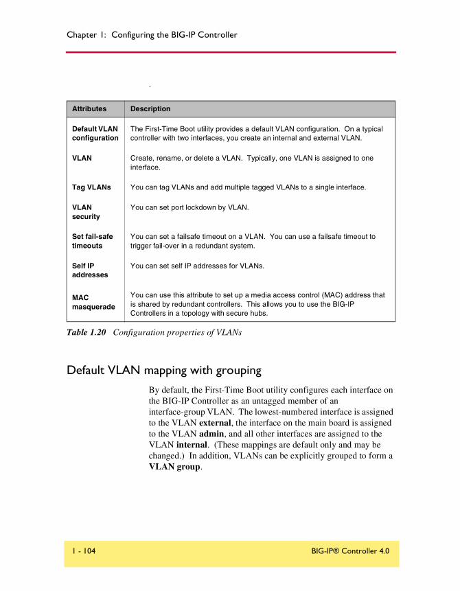
Chapter 1: Configuring the BIG-IP Controller
.
Default VLAN mapping with grouping
By default, the First-Time Boot utility configures each interface on the BIG-IP Controller as an untagged member of an interface-group VLAN. The lowest-numbered interface is assigned to the VLAN external, the interface on the main board is assigned to the VLAN admin, and all other interfaces are assigned to the VLAN internal. (These mappings are default only and may be changed.) In addition, VLANs can be explicitly grouped to form a VLAN group.
Attributes Description
Default VLAN configuration
The First-Time Boot utility provides a default VLAN configuration. On a typical controller with two interfaces, you create an internal and external VLAN.
VLAN Create, rename, or delete a VLAN. Typically, one VLAN is assigned to one interface.
Tag VLANs You can tag VLANs and add multiple tagged VLANs to a single interface.
VLAN security
You can set port lockdown by VLAN.
Set fail-safe timeouts
You can set a failsafe timeout on a VLAN. You can use a failsafe timeout to trigger fail-over in a redundant system.
Self IP addresses
You can set self IP addresses for VLANs.
MAC masquerade
You can use this attribute to set up a media access control (MAC) address that is shared by redundant controllers. This allows you to use the BIG-IP Controllers in a topology with secure hubs.
Table 1.20 Configuration properties of VLANs
1 - 104 BIG-IP® Controller 4.0

VLANs, self IPs, interfaces & trunks
This scenario creates the mapping shown in Figure 1.24.
Figure 1.24 VLANs and a VLAN group
As Figure 1.24 shows, VLAN flexibility is such that separate IP networks can belong to a single VLAN, while a single IP network can be split among multiple VLANs. (The latter case allows the BIG-IP Controller to be inserted into an existing LAN without renaming the nodes.) In either case, the separate networks can be made to behave like a single network for intercommunication purposes. This is done in one of two ways:
◆ For nodes on different networks within the same VLAN, direct packet exchange is performed using feature called VLAN bridging.
Eth
erne
t
Ethernet
BIG-IP Controller
11.1.11.2
L2 Forwarding
Ethernet
12.1.11.4
VLANinternal
Bridging
VLANextermal 12.1.11.3
VLANGROUP
MY_GROUP
Reference Guide 1 - 105

Chapter 1: Configuring the BIG-IP Controller
◆ For nodes on the same IP network on different VLANs, direct packet exchange is performed by a feature called L2 forwarding. This requires that the VLANs be grouped.
Except for self-addresses (which must be mapped explicitly to VLANs), all addresses created as objects on the BIG-IP Controller (virtual servers, NATs, SNATs, and proxies) are automatically mapped to all untagged VLANs. Thus, bridging always takes place.
Creating, renaming, and deleting VLANs
Typically, if you use the default controller configuration, one VLAN is assigned to each interface. However, if you need to change your network configuration, or if the default VLANs are not adequate for a network configuration, you can create new VLANs, rename existing VLANs, or delete a VLAN.
To create a VLAN using the Configuration utility
1. In the navigation pane, click Network.The VLANs screen opens.
2. Click the Add button to start the Add VLAN wizard.
To rename or delete a VLAN using the Configuration utility
1. In the navigation pane, click Network.The VLANs screen opens.
2. In the VLANs screen, use one of the following options:
• To rename a VLAN, click the VLAN name you want to change. The VLAN properties screen opens. Type the new name in the VLAN name box.
• To delete a VLAN, click the Delete button for the VLAN you want to delete.
1 - 106 BIG-IP® Controller 4.0
VLANs, self IPs, interfaces & trunks
To create, rename, or delete a VLAN from the command line
To create a VLAN from the command line, use the following syntax.b vlan <vlan name> interfaces add <if name> <if name>
For example, if you want to create a VLAN named myvlan that contains the interfaces 1.1 and 1.2, type the following command.b vlan myvlan interfaces add 1.1 1.2
To rename an existing VLAN, use the following syntax.b vlan <vlan name> rename <new vlan name>
For example, if you want to rename the VLAN myvlan to yourvlan, type the following command.b vlan myvlan rename yourvlan
To delete a VLAN, use the following syntax.b vlan <vlan name> delete
For example, to delete the VLAN named yourvlan, type the following command.b vlan yourvlan delete
VLAN group
A VLAN group is a grouping of two or more VLANs belonging to the same IP network for the purpose of allowing Layer 2 packet forwarding, also known as L2 forwarding, between those VLANs.
For a VLAN group to use Layer 2 forwarding, you must configure the following BIG-IP Controller features:
• The VLANs between which the packets are to be passed must be on the same IP network.
• The VLANs between which the packets are to be passed must be grouped.
• Layer 2 forwarding must be enabled for the VLAN group.
• A self IP address must be assigned to the VLAN group for routing purposes.
Reference Guide 1 - 107

Chapter 1: Configuring the BIG-IP Controller
To create a VLAN group from the command line
You can define a VLAN group from the command line using the vlangroup command. For example:b vlangroup network11 { vlans add internal external }
To assign the self IP address to the VLAN group, use the following syntax:b self <ip address> vlan <vlangroup name>
Layer 2 forwarding must be enabled for the VLAN group using the vlan proxy_forward attribute. This attribute is enabled by default when the VLAN group is enabled. To verify that proxy forwarding is enabled, type the following command:b vlans show
Check the output of the VLAN group for proxy_forward enable.
Tagging VLANs
You can create tagged VLANs, tag existing VLANs, and add multiple tagged VLANs to a single interface. There are three steps to creating multiple tagged VLANs on one interface.
• Create the VLANs you want for which you want to tag the interface.
• Mark the interface as tagged.
• Add the tagged VLANs to the tagged interface
To create a tagged VLAN using the Configuration utility
1. In the navigation pane, click Network.The VLAN screen opens.
2. Click the Add button.The Add VLAN screen opens.
3. On the Add VLAN screen, enter the VLAN name and specify the tagged interfaces by choosing them from the Resources list and clicking tagged >>.
1 - 108 BIG-IP® Controller 4.0

VLANs, self IPs, interfaces & trunks
4. Configure the other VLAN options as desired and click the Done button. (It is not necessary to fill in a VLAN tag number. This is done automatically.)
To tag an existing VLAN using the Configuration utility
1. In the navigation pane, click Network.The VLAN screen opens.
2. Click on the VLAN name in the list. The properties screen for that VLAN opens.
3. On the screen, specify the tagged interfaces by choosing them from the Resources list and clicking tagged >>. (It is not necessary to fill in a VLAN tag number. This is done automatically.)
To create a tagged VLAN from the command line
You create a new tagged VLAN using the bigpipe vlan tag command, specifying a tag number. For example: b vlan my_vlan tag 1209
A tagged VLAN is mapped to an interface or interfaces (or an untagged VLAN is tagged and mapped an interface or interfaces) using the tagged flag. For example: b vlan external interfaces add tagged 4.1 5.1 5.2
The effect of the command is to place a tag on interfaces 4.1.and 5.1, which in turn makes external a tagged VLAN. (However, it remains an untagged VLAN for interfaces which are part of it but not tagged.)
An interface can have more than one tag, for example, it can be a member of more than one tagged VLAN. b vlan external interfaces add tagged 4.1
b vlan internal interfaces add tagged 4.1
Reference Guide 1 - 109

Chapter 1: Configuring the BIG-IP Controller
Setting up security for VLANs
You can lock down a VLAN to prevent direct connection to the BIG-IP Controller through that VLAN.
To enable or disable port lockdown using the Configuration utility
1. In the navigation pane, click Network.The VLAN screen opens.
2. Click on the VLAN name in the list. The properties screen for that VLAN opens.
3. To enable port lockdown, click a check in the Port Lockdown box. To disable port lockdown, clear the check from the Port Lockdown box
To enable or disable port lockdown from the command line
To enable port lockdown, type:
b vlan <vlan_name> port_lockdown enable
To disable port lockdown, type:
b vlan <vlan_name> port_lockdown disable
Setting fail-safe timeouts for VLANs
For redundant BIG-IP Controller pairs, fail-over occurs when loss of traffic is detected on a VLAN, and traffic is not restored during the fail-over timeout period for that VLAN. You can enable a fail-safe mechanism to attempt to generate traffic when half the timeout has elapsed. If the attempt is successful, the failover is aborted.
To set the fail-over timeout and arm the fail-safe using the Configuration utility
1. In the navigation pane, click Network.The VLAN screen opens.
1 - 110 BIG-IP® Controller 4.0

VLANs, self IPs, interfaces & trunks
2. Click on the VLAN name in the list. The properties screen for that VLAN opens.
3. Check the Arm Failsafe box and specify the timeout in seconds in the Timeout box.
To set the fail-over timeout and arm the fail-safe from the command line
Using the vlan command, you may set the timeout period and also arm or disarm the fail-safe.
To set the timeout, type:b vlan <vlan_name> timeout <timeout_in_seconds>
To arm the fail-safe, type:b vlan <vlan_name> failsafe arm
To disarm the fail-safe, type:b vlan <vlan_name> failsafe disarm
Setting the MAC masquerade address
Sharing the media access control (MAC) masquerade address makes it possible to use BIG-IP Controllers in a network topology using secure hubs. The MAC address for a VLAN is the MAC address of the first interface to be mapped to the VLAN, typically 4.1 for external and 5.1 for internal. You can view the interfaces mapped to a VLAN using the following command:b vlan show
You can view the MAC addresses for the interfaces on the controller using the following command:b interface show
Reference Guide 1 - 111

Chapter 1: Configuring the BIG-IP Controller
Use the following syntax to set the MAC masquerade address that will be shared by both BIG-IP Controllers in the redundant system.b interface <ifname> mac_masq <MAC_addr>
WARNING
You must specify a default route before using the mac_masq command. You specify the default route in the /etc/hosts and /etc/netstart files.
Find the MAC address on both the active and standby units and choose one that is similar but unique. A safe technique for choosing the shared MAC address follows:
Suppose you want to set up mac_masq on the external interfaces. Using the b interface show command on the active and standby units, you note that their MAC addresses are:Active: 3.1 = 0:0:0:ac:4c:a2
Standby: 3.1 = 0:0:0:ad:4d:f3
In order to avoid packet collisions, you now must choose a unique MAC address. The safest way to do this is to select one of the addresses and logically OR the first byte with 0x40. This makes the MAC address a locally administered MAC address.
In this example, either 40:0:0:ac:4c:a2 or 40:0:0:ad:4d:f3 would be a suitable shared MAC address to use on both BIG-IP Controllers in the redundant system.
The shared MAC address is used only when the BIG-IP Controller is in active mode. When the unit is in standby mode, the original MAC address of the network card is used.
If you do not configure mac_masq, on startup, or when transitioning from standby mode to active mode, the BIG-IP Controller sends gratuitous ARP requests to notify the default router and other machines on the local Ethernet segment that its MAC address has changed. See RFC 826 for more details on ARP.
Note
The MAC masquerade information is stored in the bigip_base.conf file.
1 - 112 BIG-IP® Controller 4.0

VLANs, self IPs, interfaces & trunks
Self IP addressA self IP address is an IP address mapping to a one or more VLANs and their associated interfaces on a BIG-IP Controller. A "one true" self IP address is assigned to each interface on the controller as part of first time boot configuration, and also a floating (shared) alias for controllers in a redundant pair. You may create additional self addresses for health checking, gateway failsafe, routing, or other purposes. You can create these additional self IP addresses using the self command.
To add a self IP addresses to a VLAN in the Configuration utility
1. In the navigation pane, click Network.The VLANs page opens.
2. In the VLANs page, click the Self IP Addresses tab.The Self IP Addresses screen opens.
3. On the Self IP Addresses screen, click the Add button.The Add Self IP Address screen opens.
4. In the IP Address box, type the self IP address to be assigned.
5. In the Netmask box, you may type an optional netmask.
6. In the Broadcast box, you may type an optional broadcast address.
7. In the Floating box, click a check if you want to configure the self IP address as floating address.
8. In the SNAT Automap box, place a check if you want to enable the address for SNAT auto-mapping.
9. In the VLAN box, type the name of the VLAN to which you want to assign the self IP address.
10. Click the Done button.
Reference Guide 1 - 113

Chapter 1: Configuring the BIG-IP Controller
To add a self IP address to a VLAN using the Configuration utility
To add a self IP address to a VLAN at the command line, use the following syntax:
b self <addr> vlan <vlan_name> [ netmask <ip_mask> ][ broadcast <broadcast_addr>] [unit <id>]
You can add any number of additional self IP addresses to a VLAN to create aliases. For example:b self 11.11.11.4 vlan external
b self 11.11.11.5 vlan external
b self 11.11.11.6 vlan external
b self 11.11.11.7 vlan external
Also, any one self IP address may have floating enabled to create a floating alias that is shared by both units of a BIG-IP Controller redundant pair:b self 11.11.11.8 floating enable
Assigning a self IP address to a VLAN automatically maps it to the VLAN’s interfaces. Since all interfaces must be mapped to one and only one untagged VLAN, assigning a self IP address to an interface not mapped to an untagged VLAN produces an error message.
Enabling or disabling SNAT automap
The translation address for SNAT automapping is determined by the enablement of self IP addresses on the external VLAN. For more information about SNAT auto-mapping, refer to Enabling or disabling SNAT automap on page 1-94.
1 - 114 BIG-IP® Controller 4.0

VLANs, self IPs, interfaces & trunks
InterfaceYou can use interface attributes to configure how traffic flows through the BIG-IP Controller. Many configurations require you to set the attributes of one or more interfaces on the BIG-IP Controller.
The attributes you can configure for an interface are in Table 1.21.
Interface naming convention
By convention, the Ethernet interfaces on a BIG-IP Controller take the name <s>.<p> where s is the slot number of the NIC and p is the port number on the NIC. As shown in Figure 1.25, for vertically oriented NICs, slot numbering is left-to-right and port numbering is top-to-bottom. Note that slot 1 is reserved for the onboard NIC whether or not it is present.
Interface Attributes Description
media You may specify a media type or use auto for automatic detection.
duplex You may specify a full or half duplex mode or use auto for automatic selection.
Table 1.21 The attributes you can configure for an interface
Reference Guide 1 - 115
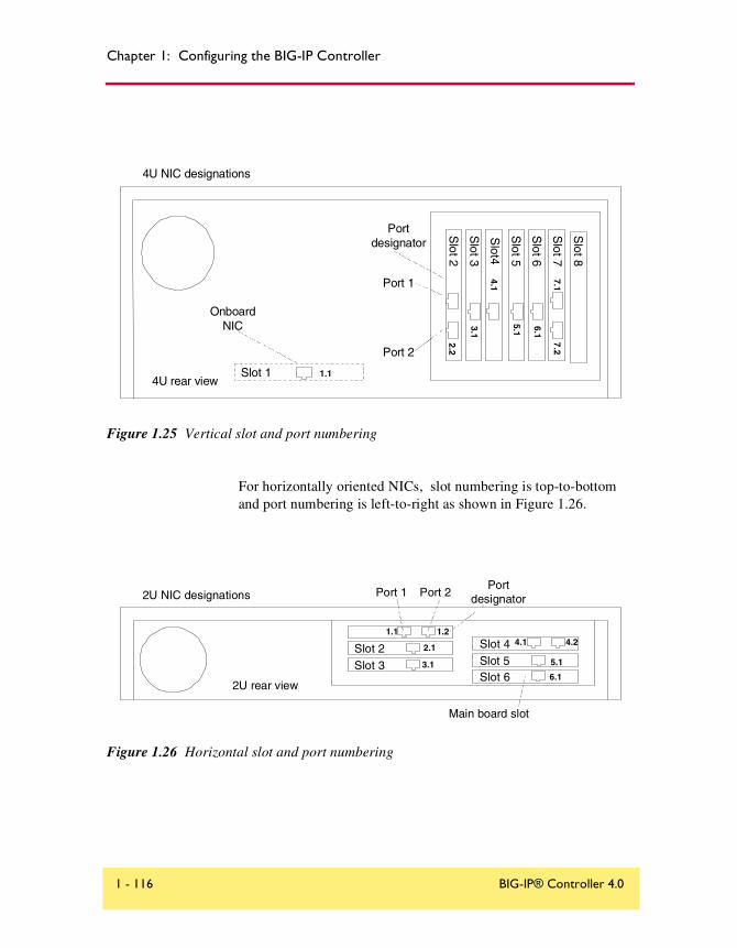
Chapter 1: Configuring the BIG-IP Controller
Figure 1.25 Vertical slot and port numbering
For horizontally oriented NICs, slot numbering is top-to-bottom and port numbering is left-to-right as shown in Figure 1.26.
Figure 1.26 Horizontal slot and port numbering
4U NIC designations
4U rear view
Port 1
Port 2
Portdesignator
Slot
3
4.1
3.1
Slot
5
Slot4
7.17.2
6.1
5.1
Slot
7
Slot
6
Slot
8
2.1S
lot2
2.2
Slot 1 1.1
OnboardNIC
2U NIC designations
Slot 2Slot 3
Slot 4Slot 5Slot 6
Main board slot
2U rear view
Port 1 Port 2
1.1 1.2
2.1
3.16.1
Portdesignator
5.1
4.1 4.2
1 - 116 BIG-IP® Controller 4.0

VLANs, self IPs, interfaces & trunks
When a list of interfaces is called for by a bigpipe command, the list may consist of one or more interfaces, with multiple interfaces separated by spaces. For example:2.1 2.2 2.4 2.6
Displaying status for interfaces
Use the following syntax to display the current status and the settings for all installed interface cards:b interface show
Figure 1.27 is an example of the output you see when you issue this command on an active/standby controller in active mode.
Use the following syntax to display the current status and the setting for a specific interface.b interface <if_name> show
Setting the media typeThe media type may be set to the specific media type for the interface card or it may be set to auto for auto detection. If the media type is set to auto and the card does not support auto detection, the default type for that interface is used, for example 1000BaseTX.
Use the following syntax to set the media type:b interface media <media_type>
interface 5.1 0:d0:b7:25:84:27 enabled status active media auto (100baseTX) duplex half (half)
interface 4.1 0:d0:b7:25:82:3d enabled status active media auto (100baseTX) duplex half (half))
Figure 1.27 The bigpipe interface show command output
Reference Guide 1 - 117
Chapter 1: Configuring the BIG-IP Controller
Setting the duplex mode
Duplex mode may be set to full or half duplex. If the media type does not allow duplex mode to be set, this is indicated by an onscreen message. If media type is set to auto, or if setting duplex mode is not supported, the duplex setting is not saved to bigip.conf.
Use the following syntax to set the duplex mode:b interface duplex full | half | auto
TrunksLink aggregation is the grouping of links (individual physical interfaces) to form a trunk. Link aggregation increases the bandwidth of the individual links in an additive manner. Thus four fast Ethernet links, if aggregated, create a single 400 Mbps link. The other advantage of link aggregation is link fail-over. If one link in a trunk goes down, traffic is simply redistributed over the remaining links.
A trunk must have a controlling link and acquires all the attributes of that controlling link from Layer 2 and above. Thus the trunk automatically acquires the VLAN membership of the controlling link but does not acquire its media type and speed. Outbound packets to the controlling link are load balanced across all of the known-good links in the trunk. Inbound packets from any link in the trunk are treated as if they came from the controlling link.
A maximum of eight links may be aggregated. For optimal performance, links should be aggregated in powers of two. Thus ideally you will aggregate two, four, or eight links.
To configure a trunk using the Configuration utility
1. In the navigation pane, click Network.The VLANs screen opens.
2. Click the Trunks tab. The Trunks screen opens.
1 - 118 BIG-IP® Controller 4.0

VLANs, self IPs, interfaces & trunks
3. On the Trunks screen, click the Add button. The Add Trunk screen opens.
4. Select the link that is to be the controlling link from the Available Interfaces list and click controlling >>. The interface appears at the top of the Aggregated Interfaces list.
5. Select the remaining link(s) from the Available Interfaces list and click aggregated >>. The interface(s) appears in the Aggregated Interfaces list below the controlling link.
6. Click Done.
To configure a trunk from the command line
Use the following syntax to configure a trunk from the command line:b trunk <controlling_if> define <if_list>
Interfaces are specified using the s.p convention, where s is slot number and p is port number. An <if_list> is one or more such interfaces, with multiple interfaces separated by spaces.
For more information on interface naming, refer to Interface naming convention on page 1-115.
Reference Guide 1 - 119

Chapter 1: Configuring the BIG-IP Controller
Health monitorsHealth monitors verify connections and services on nodes that are members of load balancing pools. The monitor checks the node at a set interval. If the node does not respond within a specified timeout period, the node is marked down and traffic is no longer directed to it.
By default, an icmp (Internet Control Message Protocol) monitor is associated with every node that is a member of a load balancing pool. This monitor is of the simplest type, checking only the node address and checking only for a ping response. To change the interval and timeout values of this default check, or to check specific services on a node, you need to configure a custom monitor or monitors to add to the default monitor. The BIG-IP Controller provides a variety of service-specific monitors in template form. Some of these monitors are usable as is (assuming their default values are acceptable) and may be put in service simply by associating them with the nodes to be monitored. In most cases, however, the template is used purely as a template for configuring custom monitors. Configuring custom monitors and placing them in service is a three-step process:
• Selecting the template
• Configuring the monitor from the template
• Associating the monitor with the node or nodes
For example, for the default icmp monitor, we selected the icmp monitor template, as shown in Figure 1.28.
The icmp monitor template has three attributes, interval, timeout, and dest, each with a default value. (All monitor templates have these three basic attributes. As will be seen, other monitor
monitor type icmp {interval 5timeout 16dest *
}
Figure 1.28 The icmp monitor template
1 - 120 BIG-IP® Controller 4.0

Health monitors
templates have additional attributes as required by the service type.) These attributes are inherited by the custom monitor when it is configured and can be left at their default values or assigned new values as required.
For the default monitor, template icmp is used as is, that is, as monitor icmp with its default attribute values. To change any of these default values, you would need to create a custom monitor based upon icmp, for example, my_icmp. Only the values that are actually to be changed would need to be specified in the definition of the custom monitor. Therefore, if you wanted to change the timeout values only, you would define the custom monitor as follows:b monitor my_icmp ’{ use icmp timeout 20 }’
This would create a new monitor in /config/bigip.conf, as shown in Figure 1.29. You can display this monitor using the command b monitor my_icmp show.
Once the custom monitor exists, you associate it with a node or nodes using the Configuration utility or the bigpipe node command as follows.
b node 11.11.11.1 11.11.11.2 11.11.11.3 monitor use my_icmp
Note
The nodes are identified by IP address only. icmp can ping addresses only, not specific ports on addresses. This creates three instances of monitor my_icmp, one for each address. You can display the instances using the command b node monitor my_icmp show.
monitor my_icmp{#type icmpuse "icmp"interval 5timeout 20}
Figure 1.29 Custom icmp monitor
Reference Guide 1 - 121

Chapter 1: Configuring the BIG-IP Controller
Note that each instance takes as its destination the selfsame node it is associated with. This is because the dest value in my_icmp was left at the default *, which tells the instance to use the associated node as its destination. Assigning a specific address to dest, such as 11.11.11.1, would cause the monitor to verify all three addresses by checking that one address, making 11.11.11.2 and 11.11.11.3 dependent on 11.11.11.1.
Selecting the monitor templateSelecting a template is straightforward. Like icmp, each of the templates has a type based on the type of service it checks, for example, http, https, ftp, pop3, and takes that type as its name. (Exceptions are port-specific templates, like https_443, and the external template, which calls a user-supplied program.) To select a template, simply choose the one that corresponds in name and/or type to the service you want to check. If more than one service is to be checked, for example http and https, more than one monitor can be placed on the node. (This creates a rule, namely that the node will not be considered up unless both monitors run successful
+- NODE ADDRESS 11.11.11.1 UP| || +- icmp| 11.11.11.1 up enabled |+- NODE ADDRESS 11.11.11.2 UP| || +- icmp| 11.11.11.2 up enabled |+- NODE ADDRESS 11.11.11.3 UP | +- icmp 11.11.11.3 up enabled
Figure 1.30 Output for the command b node monitor show
1 - 122 BIG-IP® Controller 4.0

Health monitors
checks.) You may not want to check all services available on a node specifically. If you want to verify only that the destination IP address is alive, or that the path to it through a transparent node is alive, use one of the simple templates, icmp or tcp_echo. If you want to verify TCP only, use the monitor template tcp.
All monitor templates are contained in the read-only file /etc/base_monitors.conf. The following sections describe each of the monitor templates, its function, and the information required to configure a monitor from it. The templates are divided into three groups based on the types of monitors they support: simple monitors, ECV (Extended Content Verification) monitors, and EAV (Extended Application Verification) monitors. Also described are the port-specific monitor templates, which are derived from the other types.
Working with templates for simple monitors
Simple monitors are those that check node addresses only and verify simple connections only. Templates for these monitors are icmp and tcp_echo.
Note
The templates icmp and tcp_echo are both usable as is, that is, they may be associated with nodes. It is important to understand, however, that using a template as is means that you are using the default attribute values. To change any of these values, you have to configure a custom monitor based on the template.
Reference Guide 1 - 123

Chapter 1: Configuring the BIG-IP Controller
Using icmp
The icmp template uses Internet Control Message Protocol to make a simple node check. The check is successful if a response to an ICMP_ECHO datagram is received. icmp has no attributes other than the standard interval, timeout, and dest.
Using tcp_echo
The tcp_echo template uses Transmission Control Protocol. The check is successful if a response to a TCP ECHO message is received. tcp_echo also supports transparent mode. In this mode, the node with which the monitor is associated is pinged through to the destination node. (For more information about transparent mode, refer to Using transparent and reverse modes on page 1-137.)
To use tcp_echo, you must ensure that TCP ECHO is enabled on the nodes being monitored.
monitor icmp {type icmpinterval 5timeout 16dest *}
Figure 1.31 The icmp monitor template
monitor tcp_echo {type tcp_echointerval 5timeout 16dest *
//transparent }
Figure 1.32 The tcp_echo monitor template
1 - 124 BIG-IP® Controller 4.0

Health monitors
Working with templates for ECV monitors
ECV monitors attempt to retrieve explicit content from nodes using send and recv statements. These include http, https and tcp.
Note
The templates http, https, and tcp are all usable as is, and you may associate them with nodes. It is important to understand, however, that using a template as is means that you are using the default attribute values. To change any of these values, you have to configure a custom monitor based on the template.
Using tcp
The tcp template is for Transmission Control Protocol. A tcp monitor attempts to receive specific content. The check is successful when the content matches the recv expression. A tcp monitor takes a send string and a recv expression. If the send string is left blank, the service is considered up if a connection can be made. A blank recv string matches any response. Both transparent and reverse modes are options. (For more information about transparent and reverse modes, refer to Using transparent and reverse modes on page 1-137.)
monitor tcp {
# type tcpinterval 5timeout 16dest *:*send ""recv ""//reverse//transparent}
Figure 1.33 The tcp monitor template
Reference Guide 1 - 125

Chapter 1: Configuring the BIG-IP Controller
Using http
The http template is for HyperText Transfer Protocol. Like a tcp monitor, an http monitor attempts to receive specific content from a web page, and unlike a tcp monitor, sends a user name and password. The check is successful when the content matches the recv expression. An http monitor uses a send string, a recv expression, username, password, and optional get, url, transparent and reverse statements. (If there is no password security, use blank strings [""] for username and password.) The optional get statement replaces the send statement, automatically filling in the string "GET". Thus the following two statements are equivalent:send "GET/"get "/"
The optional url statement takes the HTTP URL as a value and automatically fills in the dest value with the address the URL resolves to. (For more information about transparent and reverse modes, refer to Using transparent and reverse modes on page 1-137.) Both transparent and reverse modes are also options. (For more information about the get and url statements, refer to Using send, receive, url, and get statements on page 1-136.)
monitor http {type httpinterval 5timeout 16dest *:*send "GET /"recv ""username ""password ""//get//url//reverse//transparent}
Figure 1.34 The http monitor template
1 - 126 BIG-IP® Controller 4.0
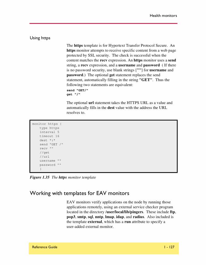
Health monitors
Using https
The https template is for Hypertext Transfer Protocol Secure. An https monitor attempts to receive specific content from a web page protected by SSL security. The check is successful when the content matches the recv expression. An https monitor uses a send string, a recv expression, and a username and password ( If there is no password security, use blank strings [""] for username and password.) The optional get statement replaces the send statement, automatically filling in the string "GET". Thus the following two statements are equivalent:send "GET/"get "/"
The optional url statement takes the HTTPS URL as a value and automatically fills in the dest value with the address the URL resolves to.
Working with templates for EAV monitors
EAV monitors verify applications on the node by running those applications remotely, using an external service checker program located in the directory /user/local/lib/pingers. These include ftp, pop3, smtp, sql, nntp, lmap, idap, and radius. Also included is the template external, which has a run attribute to specify a user-added external monitor.
monitor https {type httpsinterval 5timeout 16dest *:*send "GET /"recv ""//get//urlusername ""password ""}
Figure 1.35 The https monitor template
Reference Guide 1 - 127

Chapter 1: Configuring the BIG-IP Controller
Using ftp
The ftp template is for File Transfer Protocol. The monitor attempts to download a specified file to the /var/tmp directory. The check is successful if the file is retrieved. The ftp monitor takes a get statement, username, and password. The get statement takes the full path to the file as a value. The optional url statement may be used in place of get. The url takes the FTP URL as a value and automatically fills in the dest value with the address the URL resolves to. (For more information about the get and url statements, refer to Using send, receive, url, and get statements on page 1-136.)
Using pop3
The pop3 template is for Post Office Protocol. The check is successful if the monitor is able to connect to the server, log in as the indicated user, and log out. The pop3 monitor requires username and password.
monitor ftp {type ftpinterval 5timeout 16dest *:*username ""password ""get ""//url}
Figure 1.36 The ftp monitor template
monitor pop3 {type pop3interval 5timeout 16dest *:*username ""password ""}
Figure 1.37 The pop3 monitor template
1 - 128 BIG-IP® Controller 4.0

Health monitors
Using smtp
The smtp template is for Simple Mail Transport Protocol servers. An smtp monitor is an extremely simple monitor that checks only that the server is up and responding to commands. The check is successful if the mail server responds to the standard SMTP HELO and QUIT commands. An smtp monitor requires a domain name.
Using nntp
The nntp template is for Usenet News. The check is successful if the monitor retrieves a newsgroup identification line from the server. An nntp monitor requires a newsgroup name (for example, “alt.cars.mercedes”) and, if necessary, username and password.
monitor smtp {type smtpinterval 5timeout 16dest *:*domain ""}
Figure 1.38 The smtp monitor template
monitor nntp {type nntpinterval 5timeout 16dest *:*username ""password ""newsgroup ""}
Figure 1.39 The nntp monitor template
Reference Guide 1 - 129

Chapter 1: Configuring the BIG-IP Controller
Using sql
The sql template is for service checks on SQL-based services such as Microsoft SQL Server versions 6.5 and 7.0, and also Sybase. The service checking is accomplished by performing an SQL login to the service. An executable program, tdslogin performs the actual login. The check is successful if the login succeeds.
An sql monitor requires a database (for example, "server_db"), username, and password.
Using imap
The imap template is for Internet Message Access Protocol. The imap monitor is essentially a pop3 monitor with the addition of the attribute folder, which takes the optional key message_num. The check is successful if the specified message number is retrieved. An imap monitor requires username, password, and a folder. It also takes an optional message number, message_num.
monitor sql {type sqlinterval 5timeout 16dest *:*username ""password ""database ""}
Figure 1.40 The sql monitor template
monitor imap {type imapinterval 5timeout 16dest *:*username ""password ""folder ""/message_num ""}
Figure 1.41 The imap monitor template
1 - 130 BIG-IP® Controller 4.0

Health monitors
Using radius
The radius template is for Remote Access Dial-in User Service servers. The check is successful if the server authenticates the requesting user. A radius monitor requires a username, a password, and a shared secret string secret for the code number.
Note
Servers to be checked by a radius monitor typically require special configuration to maintain a high level of security while also allowing for monitor authentication.
Using ldap
The ldap template is for Lightweight Directory Access Protocol, which implements standard X.500 for e-mail directory consolidation. A check is successful if entries are returned for the base and filter specified. An ldap monitor requires a username, a password, and a base and a filter string. The username is a distinguished name, that is, an LDAP-format user name. The base is the starting place in the LDAP hierarchy from which to begin the query. The filter is an LDAP-format key of what is to be searched for.
monitor radius {type radiusinterval 5timeout 16dest *username ""password ""secret ""}
Figure 1.42 The radius monitor template
Reference Guide 1 - 131

Chapter 1: Configuring the BIG-IP Controller
Note
Servers to be checked by an imap monitor typically require special configuration to maintain a high level of security while also allowing for monitor authentication.
Using external
The external template is for a user-supplied monitor. An external monitor requires the executable name (run) of that monitor and any command line arguments (args) required.
Configuring a monitorThe second step in creating a monitor and placing it in service is to configure the monitor from the monitor template. Configuring a monitor consists of giving it a name distinct from the monitor
monitor ldap {type ldapinterval 5timeout 16dest *:*username ""password ""base ""filter ""}
Figure 1.43 A Sample monitor template
monitor external {type externalinterval 5timeout 16dest *:*run ""args ""}
Figure 1.44 The external monitor template
1 - 132 BIG-IP® Controller 4.0

Health monitors
template name and assigning values to all attributes that are not to be left at their default values (and adding any optional attributes that are not present by default, like reverse or transparent). You can do this using the Configuration utility or at the command line using the bigpipe monitor command.
To configure a monitor using the Configuration utility
1. In the navigation pane, click Monitors.The Network Monitors screen opens.
2. Click the Add button.The Add Monitor screen opens.
3. In the Add Monitor screen, type in the name of your monitor (it must be different from the monitor template name), and choose the monitor template you want to use.
4. Click the Next button and you will be guided through the configuration of your monitor.For additional information configuring a Monitor, click the Help button.
To configure a monitor from the command line
Use the bigpipe monitor command to configure the monitor at the command line. If the monitor is to be defined with all attributes set to their default values, type:b monitor <name> ’{ use <template_name> }’
If you want to set one or more attributes to a new value, specify only those attributes and their values. For example, to create a tcp_echo monitor my_tcp_echo in bigpipe using the default values for the attributes interval, timeout, and dest, you would type:b monitor my_tcp ’{ use tcp_echo }’
If any of the default values are to be changed, only these changes need to be specified. For example:
b monitor my_tcp-echo ’{ use tcp_echo interval 10 timeout 20 }’
Reference Guide 1 - 133

Chapter 1: Configuring the BIG-IP Controller
If an optional attribute is to be used, like transparent, add it to the list:
b monitor my_tcp-echo ’{ use tcp_echo interval 10 timeout 20 transparent }’
Table 1.22 provides a summary of the monitor attributes and their definitions. For more information on the monitor templates and attributes, refer to Selecting the monitor template on page 1-122.
Attribute Definition
interval <seconds> Ping frequency time interval in seconds.
timeout <seconds> Ping timeout in seconds.
dest <node_addr> Ping destination node. <node_address> Usually *:* for simple monitors, *:* for all others, causing the monitor instance to ping the address or address:port for which it is instantiated. Specifying address and/or port forces the destination to that address/port.
send <string> Send string for ECV. Default send and recv values are empty (""), matching any string.
recv <string> Receive expression for ECV. Default send and recv values are empty (""), matching any string.
get <string> For the http and https monitors get replaces the recv statement, automatically filling in "GET". For the ftp monitor get can be used to specify a full path to a file. This automatically fills in dest.
url For the http and https, and ftp monitors, url replaces the recv statement, supplies a URL and automatically fills in dest with the URL address.
reverse A mode that sets the node down if the received content matches the recv string.
transparent A mode that forces pinging through the node to the dest address for transparent nodes, such as firewalls.
run <program> An external user-added EAV program.
Table 1.22 Monitor attributes
1 - 134 BIG-IP® Controller 4.0

Health monitors
Entering string valuesExcept for interval, timeout, and dest, you should enter all attribute values as quoted strings, even if they are numeric, as in the case of code numbers.
args <program_args> List of command line arguments for external program. The args are quoted strings set apart by spaces.
username <username> Username for services with password security. For ldap this is a distinguished, that is, LDAP-format user name.
password <password> Password for services with password security.
newsgroup <newsgroup> Newsgroup, for type nntp EAV checking only
database <database> Database name, for type sql EAV checking only.
domain <domain_name> Domain name, for type smtp EAV checking only
secret Shared secret for radius EAV checking only.
folder Folder name for imap EAV checking only.
message_num Optional message number for imap EAV.
base Starting place in the LDAP hierarchy from which to begin the query, for ldap EAV checking only.
filter LDAP- format key of what is to be searched for, for ldap EAV checking only.
Attribute Definition
Table 1.22 Monitor attributes
Reference Guide 1 - 135

Chapter 1: Configuring the BIG-IP Controller
Setting destinations
By default, all dest values are set to the wildcard "*" or "*:*". This causes the monitor instance created for a node to take that node’s address or address and port as its destination. An explicit dest value is used only to force the instance destination to a specific address and/or port which may not be that of the node. For more information about setting destinations, refer to Associating the monitor with a node or nodes on page 1-143.
Using send, receive, url, and get statements
The ECV monitor templates http, https, and tcp have the attributes send and recv for the send string and receive expression, respectively.
The most common send string is “GET /” which simply retrieves a default HTML page for a web site. To retrieve a specific page from a web site, simply enter a fully qualified path name:"GET /www/support/customer_info_form.html"
The receive expression is the text string the monitor looks for in the returned resource. The most common receive expressions contain a text string that would be included in a particular HTML page on your site. The text string can be regular text, HTML tags, or image names.
The sample receive expression below searches for a standard HTML tag."<HEAD>"
You can also use the default null recv value "". In this case, any content retrieved is considered a match. If both send and recv are left empty, only a simple connection check is performed.
For http and ftp, the special attributes get or url may be used in place of send and recv statements. get takes the full path to the file as a value and automatically fills in the dest value with the address the path resolves to. The following two statements are equivalent:
1 - 136 BIG-IP® Controller 4.0

Health monitors
send "GET/"get "/"
url takes the URL as a value and automatically fills in the dest value with the address the URL resolves to. The URL is then resolved to supply the dest address automatically. The third statement below is equivalent to the first two combined:dest 198.192.112.13:22get "/"
url "ftp://www.my_domain.com/"
Using transparent and reverse modes
The ECV monitors have optional keywords transparent and reverse. (transparent may also be used by tcp_echo.) The normal and default mode for a monitor is to ping the dest node by an unspecified route and to mark the node up if the test is successful. There are two other modes, transparent and reverse.
In transparent mode, the monitor is forced to ping through the node it is associated with, usually a firewall, to the dest node. (In other words, if there are two firewalls in a load balancing pool, the destination node will always be pinged through the one specified and not through the one picked by the load balancing method.) In this way, the transparent node is tested as well: if there is no response, the transparent node is marked down. For more information about transparent mode, refer to Using transparent mode on page 1-146.
In reverse mode, the monitor marks the node down when the test is successful. For example, if the content on your web site home page is dynamic and changes frequently, you may want to set up a reverse ECV service check that looks for the string "Error". A match for this string would mean that the web server was down. Transparent mode can also be used with tcp_echo.
Transparent and reverse modes cannot be used on the same monitor.
Reference Guide 1 - 137
Chapter 1: Configuring the BIG-IP Controller
Testing SQL service checks
SQL service checks may require manual testing before being implemented in a monitor, as follows:cd /usr/local/lib/pingers
./tdslogin 192.168.1.1 1433 mydata user1 mypass1
Replace the IP address, port, database, user, and password in this example with your own information.
You should receive the message: Login succeeded!
If you receive the connection refused message, verify that the IP and port are correct.
If you are still having trouble, you should verify that you can log in using another tool. For example, if you have Microsoft NT SQL Server version 6.5, there is a client program ISQL/w included with the SQL software. This client program performs simple logins to SQL servers. Use this program to test whether you can login using the ISQL/w program before attempting logins from the BIG-IP Controller.
On the SQL Server, you can run the SQL Enterprise Manager to add logins. When first entering the SQL Enterprise Manager, you may be prompted for the SQL server to manage.
You can register servers by entering the machine name, user name, and password. If these names are correct, the server will be registered and you will be able to click an icon for the server. When you expand the subtree for the server, there will be an icon for Logins.
Underneath this subtree, you can find the SQL logins. Here, you can change passwords or add new logins by right-clicking the Logins icon. Click this icon to open an option to Add login. After you open this option, enter the user name and password for the new login, as well as which databases the login is allowed to access. You must grant the test account access to the database you specify in the EAV configuration.
1 - 138 BIG-IP® Controller 4.0

Health monitors
Running user-added EAVs
You may add your own monitors to those contained in /user/local/lib/pingers. For running these added programs, the monitor template external is used. The executable program is specified as the value of the attribute run. By default the monitor will look for the run program in /user/local/lib/pingers. If the program resides elsewhere, a fully qualified pathname must be entered. Any command line arguments to be used with the program are entered as args values. For example, suppose the program my_pinger is to be run with a -q option, so that it would be entered on the command line as follows:my_pinger -q
This monitor might be specified as follows:b monitor custom ’{ use external run "my_pinger" args "-q" }’
Alternatively, you may pass arguments to the external monitor as environment variables. For example, you might want to enter this command:/var/my_pinger /www/test_files/first_test
This could be specified in the conventional manner:b monitor custom ’{ use external run "/var/my_pinger" args
"www/test_files/first_test" }’
It could also be specified in this way:b monitor custom ’{ use external run "/var/my_pinger" DIRECTORY "
"www/test_files" FILE "first_test" }’
This defines the monitor as shown in Figure 1.45.
monitor custom { use externalrun "/var/my_pinger"DIRECTORY "www/test_files" FILE "first_test" }
Figure 1.45 Monitor template for an external monitor
Reference Guide 1 - 139

Chapter 1: Configuring the BIG-IP Controller
This frees the monitor definition from the rigidity of a strictly ordered command line entry. The arguments are now order-independent and may be used or ignored by the external executable.
Showing, disabling, and deleting monitors
Showing, disabling, and deleting monitors can be performed in the Configuration utility or at the command line. Deleting a monitor removes it from the /config/bigip.conf file. Disabling a monitor instance simply removes that instance from service until it is re-enabled. Disabling a monitor (which can be performed only at the command line) disables all instances of the monitor. All monitor instances are enabled by default.
To show or delete a monitor using the Configuration utility
1. In the navigation pane, click Monitors.A screen opens that lists monitors in two columns, System Supplied and User Defined.
2. To show a monitor, simply click the monitor name.
3. To delete a monitor, click the Delete button for the monitor. Note that only user-defined monitors can be deleted.
To show a monitor from the command line
You can display a selected monitor or all monitors using the bigpipe monitor show command:b monitor <name> show
b monitor show all
To delete a monitor from the command line
You can delete a selected monitor using the bigpipe monitor delete command:b monitor <name> delete
1 - 140 BIG-IP® Controller 4.0

Health monitors
To disable a monitor instance using the Configuration utility
1. In the navigation pane, click Monitors.The Monitors screen appears.
2. Click the appropriate tab for the monitor instances: Basic Associations, Node Associations, or Node Address Associations. The resulting screen will show the existing associations (monitor instances).
3. Click the node you want to disable.The Properties screen for that node opens.
4. In the Monitor Instances portion of the screen, clear the Enable check box.
5. Click Apply.The monitor instance is now disabled.
To disable a monitor or monitor instance from the command line
To disable a monitor, use the bigpipe monitor <name> disable command: b monitor <name> disable
Reference Guide 1 - 141

Chapter 1: Configuring the BIG-IP Controller
This has the effect of disabling all instances of the monitor, as shown in Figure 1.46.
To disable a monitor instance, use the bigpipe monitor instance <addr:port> disable command:b monitor instance <addr:port> disable
Disabled monitors and instances may be re-enabled as follows:b monitor <name> enable
b monitor instance <addr:port> enable
To delete a monitor from the command line
You can delete a monitor with no existing node associations and no references in a monitor rule. To delete a monitor, use the bigpipe monitor <name> delete command:b monitor my_http delete
If the monitor has instances, the instances must first be deleted using the bigpipe node <addr:port> monitor delete command. (Refer to Showing and deleting associations on page 1-149.)
+- NODE 11.12.11.20:80 UP| || +- http| 11.12.11.20:80 up disabled |+- NODE 11.12.11.21:80 UP| || +- http| 11.12.11.21:80 up disabled |+- NODE 11.12.11.22:80 UP | +- http 11.12.11.22:80 ip disabled
Figure 1.46 All monitor instances disabled
1 - 142 BIG-IP® Controller 4.0

Health monitors
Associating the monitor with a node or nodesNow that your monitor exists, the next step is to associate it with the nodes to be monitored. This creates an instance of the monitor for each node. At the command line, association is done using bigpipe node command:b node <addr_list> monitor use <name>
For example, to associate monitor http with nodes 11.12.11.20:80, 11.12.11.21:80, and 11.12.11.22:80, the bigpipe node command would be as follows:
b node 11.12.11.20:80 11.12.11.21:80 11.12.11.22:80 monitor use http
This creates a monitor instance of http for each of these nodes. You can verify this association using the bigpipe monitor show command:b node monitor show
This would produce the output shown in Figure 1.47.
The actual monitor instance for each node is represented by the output lines highlighted with bold text in Figure 1.47.
+- NODE 11.12.11.20:80 UP| || +- http| 11.12.11.20:80 up enabled |+- NODE 11.12.11.21:80 UP| || +- http| 11.12.11.21:80 up enabled |+- NODE 11.12.11.22:80 UP | +- http 11.12.11.22:80 ip enabled
Figure 1.47 The output of the b node monitor show command
Reference Guide 1 - 143

Chapter 1: Configuring the BIG-IP Controller
Reviewing types of association
While the term node association is applied generally, there are three types of association based on whether the monitor is associated with an address and a port, address(es) only, or port only. These are node association, address association, and port association.
• Node association, strictly defined, is the association of a monitor with an address and port.
• Address association is the association of a monitor with an address only.
• Port association is the association of a monitor with a port only. For a port association, a wildcard character (*) is used to represent all addresses.
Once a monitor has been associated with a node, address, or port, no other monitor can be associated with the same node, address or port. However, an address association does not prevent a monitor from being associated with a node of the same address, or vice versa.
Using a simple association
The http example given above is the simplest kind of association, a node association performed using a monitor with a dest value of *:*. It can be seen in Figure 1.34, on page 1-126, that in each case the instance destination node is identical to the node the monitor has been associated with. This is because the template http, shown in Figure 1.34, was used as is, with a dest value of *:*. Either or both wildcard symbols can be replaced by an explicit dest value by creating a new monitor based on http. This is referred to as node and port aliasing, described below.
Using node and port aliasing
Usually the health of a node is checked by pinging that node. For this reason the dest attribute in the monitor template is always set to "*" or "*:*". This causes the monitor instance created for a node to take that node’s address or address and port as its destination. An explicit dest value forces the instance destination
1 - 144 BIG-IP® Controller 4.0

Health monitors
to a specific address and/or port which may not be that of the node. This causes the monitor to ping that forced destination by an unspecified path. Suppose, for example, that the association performed using http instead used a monitor my_http with a dest value of *:443. The node association command would be identical except that http is now replaced with my_http:
b node 11.12.11.20:80 11.12.11.21:80 11.12.11.22:80 monitor use my_http
This would create three instances of the monitor with the following dest values as shown in Figure 1.48.
This is referred to as port aliasing. The node itself can also be aliased, by assigning an explicit address to dest. For example, dest could set to 11.11.11.1:80. This is called node aliasing and for the
+- NODE 11.12.11.20:80 UP| || +- my_http| 11.12.11.20:443 up enabled |+- NODE 11.12.11.21:80 UP| || +- my_http| 11.12.11.21:443 up enabled |+- NODE 11.12.11.22:80 UP | +- my_http 11.12.11.22:443 up enabled
Figure 1.48 Node ports aliased
Reference Guide 1 - 145

Chapter 1: Configuring the BIG-IP Controller
nodes 11.12.11.20:80, 11.12.11.21:80, and 11.12.11.21:80 it would produce the following instances, (which are in fact one instance associated with three different nodes) as shown in Figure 1.49.
Using transparent mode
Sometimes it is necessary to ping the aliased destination through a transparent node. Common examples are checking a router, or checking a mail or FTP server through a firewall. For example, you might want to check the router address 10.10.10.53:80 through a transparent firewall 10.10.10.101:80. To do this, you would specify 10.10.10.53:80 as the monitor dest address (a node alias) and add the flag transparent:
b monitor http_trans ’{ use http dest 10.10.10.53:80 transparent }’
Then you would associate the monitor http_trans with the transparent node:b node 10.10.10.101:80 monitor use http_trans
+- NODE 11.12.11.20:80 ADDR UP| || +- my_http| 11.11.11.1:80 checking enabled |+- NODE 11.12.11.21:80 ADDR UP| || +- my_http| 11.11.11.1:80 checking enabled |+- NODE 11.12.11.22:80 ADDR UP | +- my_http 11.11.11.1:80 checking enabled
Figure 1.49 Node addresses aliased
1 - 146 BIG-IP® Controller 4.0

Health monitors
This causes the address 10.10.10 53:80 to be checked through 10.10.10.101:80. (In other words, the check of 10.10.10.53:80 is routed through 10.10.10.101:80.) If the correct response is not received from 10.10.10.53:80, then 10.10.10.101:80 is marked down.
Note
Transparent mode applies only to the ECV monitors and to tcp_echo.)
Using logical grouping
In the examples above, only one monitor has been associated with the nodes. You may associate more than one monitor with a node or nodes by joining them with the Boolean operator and. This creates a rule, and the node is marked down if the rule evaluates to false, that is, if not all the checks are successful. The most common example is use of an HTTP monitor and an HTTPS monitor:b node 11.12.11.20:80 monitor use my_http and my_https
The monitors themselves must be configured with the grouping in mind. For example, if the dest values of both monitors were set to *:*, then both monitor instances would try to ping the default port 80. This would both defeat the purpose of the HTTPS monitor and cause an automatic failure, since two monitors would be trying to ping the same address and port simultaneously.
Reference Guide 1 - 147

Chapter 1: Configuring the BIG-IP Controller
Instead, monitor my_http should be given a dest value of *:* and monitor my_https should be given a dest value of *:443. This causes only the my_http monitor instances to default to 80. The my_https monitor instances are forced to the explicit port 443, avoiding a conflict as shown in Figure 1.50.
Using wildcards to specify addresses
The wildcard * can be used to specify addresses. A wildcard address association will create instances of the monitor for all nodes load balanced by the BIG-IP Controller:b node * monitor use my_tcp_echo:
A wildcard with a port association creates instances of the monitor for every node configured to service that port:b node *:80 monitor use my_http:
To associate a monitor using the Configuration utility
1. In the navigation pane, click Monitors.The Network Monitors screen opens.
MONITOR my_http and https_443|+- NODE 11.12.11.20:80 UP| || +- my_http| | 11.12.11.20:80 up enabled | || +- https_443 11.12.11.20:443 up enabled
Figure 1.50 Use of a rule
MONITOR my_tcp_echo (default node address monitor)
Figure 1.51 Wildcard address association
MONITOR my_http (default port 80 monitor)
Figure 1.52 Wildcard address with port association
1 - 148 BIG-IP® Controller 4.0

Health monitors
2. Click one of three tabs:
a) If you are associating the monitor with a node (the IP address plus the port) click the Node Associations tab.
b) If you are associating the monitor with a node address only (the IP address minus the port), click the Node Address Associations tab.
c) If you are associating the monitor with a port only (the port minus the IP address), click the Port Associations tab.
3. Regardless of the selection you made in step 2, a dialog box appears with the entry fields Choose Monitor and Monitor Rule. Enter the monitor or select one from the list.
4. If more than one monitor is to be associated, click the move >> button to enter the monitor selected in the Monitor Rule box.
5. Repeat the previous two steps for each monitor to be associated.
6. Click Apply to associate the monitor(s).For additional information associating a Monitor, click the Help button.
Showing and deleting associations
There are node commands for showing, and deleting node associations.
To show or delete associations using the Configuration utility
1. In the navigation pane, click Monitors.The Network Monitors screen opens.
Reference Guide 1 - 149

Chapter 1: Configuring the BIG-IP Controller
2. Click one of three tabs:
a) If you are showing or deleting a node association (a node is the IP address plus the port) click the Node Associations tab.
b) If you are showing or deleting a node address association (the IP address minus the port), click the Node Address Associations tab.
c) If you are showing or deleting a port association (the port minus the IP address), click the Port Associations tab.
3. Regardless of the selection you made in step 2, a dialog box appears showing existing associations and with a Delete Existing Associations check box. Delete associations by checking the box, then clicking Apply. Note that for wildcard address associations, the wildcard (*) association itself is shown in addition to each of the individual associations it produces. To delete all these associations, it is necessary to delete the wildcard association.
To show associations from the command line
You can display a selected node association or all node associations using the bigpipe node monitor show command:b node monitor show
b node <addr:port> monitor show
To delete associations from the command line
You can delete a selected node association or all node associations using the bigpipe node monitor delete command:b node <addr:port> monitor delete
In deleting specific monitor instances, it is important to consider how the association was made. If a monitor instance was created using a wildcard address, the wildcard must be deleted. For example, if multiple associations were created by entering b node *:80 monitor use my_tcp_echo, you would delete it by typing:
1 - 150 BIG-IP® Controller 4.0

Health monitors
b node *:80 monitor delete
If multiple associations were created by entering b node * monitor use my_tcp_echo, you would delete it by typing:b node * monitor delete
Reference Guide 1 - 151

Chapter 1: Configuring the BIG-IP Controller
Redundant systemsRedundant BIG-IP Controller systems have special settings that you need to configure, such as VLAN fail-safe settings. One convenient aspect of configuring a redundant system is that once you have configured one of the controllers, you can simply copy the configuration to the other controller in the system using the configuration synchronization feature.
There are two basic aspects about working with redundant systems:
• Synchronizing configurations between two controllers
• Configuring fail-safe settings for the VLANs
In addition to the simple redundant features available on the BIG-IP Controller, several advanced redundant features are available. Advanced redundant system features provide additional assurance that your content is available if a BIG-IP Controller experiences a problem. These advanced redundant system options include:
• Mirroring connection and persistence information
• Gateway fail-safe
• Network-based fail-over
• Setting a specific BIG-IP Controller to be the active controller
• Setting up active-active redundant controllers
The attributes you can configure for a redundant systems are shown in Table 1.23.
Attributes Description
Synchronizing configurations
This feature allows you to configure one controller and then synchronize the configuration with the other controller.
Fail-safe for VLANs
Fail-safe for VLANs provides the ability to cause a controller to fail over if a VLAN is no longer generating traffic.
Table 1.23 The attributes you can configure for redundant systems
1 - 152 BIG-IP® Controller 4.0

Redundant systems
Synchronizing configurations between controllers
Once you complete the initial configuration on the first controller in the system, you can synchronize the configurations between the active unit and the standby unit. When you synchronize a configuration, the following configuration files are copied to the other BIG-IP Controller:
• The common BIG/db keys
• All files in /config
• All common files in /etc
Mirroring connections and persistence information
You can mirror connection and/or persistence information between redundant controllers. This enables you to provide seamless fail-over of client connections.
Gateway fail-safe This feature allows you to fail-over between two gateway routers.
Network-based fail-over
You can configure the BIG-IP Controller to use the network to determine the status of the active controller.
Setting a dominant controller
You can set up one controller in a pair to be the dominant active controller. The controller you set up as the dominant controller will always attempt to be active.
Active-active configuration
The default mode for a BIG-IP Controller redundant system is Active/Standby. However, you can configure both controllers to run in active mode.
Attributes Description
Table 1.23 The attributes you can configure for redundant systems
Reference Guide 1 - 153

Chapter 1: Configuring the BIG-IP Controller
If you use command line utilities to set configuration options, be sure to save the current configuration to the file before you use the configuration synchronization feature. (Alternatively, if you want to test the memory version on the standby unit first, use bigpipe config sync running.)
Use the following bigpipe command to save the current configuration:b save
Note
A file named /usr/local/ucs/cs_backup.ucs is created prior to installing a UCS from a remote machine.
To synchronize the configuration using the Configuration utility
1. In the navigation pane, click System.The Network Map screen opens.
2. Click the Redundant Properties tab.The Redundant Properties screen opens.
3. Click the Synchronize Configuration button.
To synchronize the configuration from the command line
Synchronize the configuration from the command line using the bigpipe config sync command. Using the bigpipe config sync without the all option to synchronize only the boot configuration file /config/bigip.conf.
bigpipe config sync all synchronizes the following configuration files:
• The common BIG/db keys
• All files in /config
• All common files in /etc
1 - 154 BIG-IP® Controller 4.0
Redundant systems
The config sync running command synchronizes the running version of /config/bigip.conf, which is the image that resides in memory as the system runs. This file is written only to memory on the standby unit, it is not saved.
Configuring fail-safe settingsFor maximum reliability, the BIG-IP Controller supports failure detection on both internal and external VLANs. When you arm the fail-safe option on a VLAN, the BIG-IP Controller monitors network traffic going through the VLAN. If the BIG-IP Controller detects a loss of traffic on an VLAN when half of the fail-safe timeout has elapsed, it attempts to generate traffic. A VLAN attempts to generate network traffic by issuing ARP requests to nodes accessible through the VLAN. Also, an ARP request is generated for the default route if the default router is accessible from the VLAN. Any traffic through the VLAN, including a response to the ARP requests, averts a fail-over.
If the BIG-IP Controller does not receive traffic on the VLAN before the timer expires, it initiates a fail-over, switches control to the standby unit, and reboots.
WARNING
You should arm the fail-safe option on a VLAN only after the BIG-IP Controller is in a stable production environment. Otherwise, routine network changes may cause fail-over unnecessarily.
Arming fail-safe on a VLAN
Each interface card installed on the BIG-IP Controller is mapped to a different VLAN, which you need to know when you set the fail-safe option on a particular VLAN. You can view VLAN names in the Configuration utility, or you can use the bigpipe vlan show command to VLAN names from the command line.
Reference Guide 1 - 155

Chapter 1: Configuring the BIG-IP Controller
To arm fail-safe on an interface using the Configuration utility
1. In the navigation pane, click Network.The VLANs list opens and displays each VLAN.
2. Select a VLAN name.The VLAN Properties screen opens.
3. Check Arm Failsafe to turn on the fail-safe option for the selected VLAN.
4. In the Timeout box, type the maximum time allowed for a loss of network traffic before a fail-over occurs.
5. Click the Apply button.
To arm fail-safe on a VLAN from the command line
If you need to look up the names of the existing VLANs, use the bigpipe vlan command with the show keyword:b vlan show
To arm fail-safe on a particular VLAN, use the bigpipe vlan command with the failsafe arm keyword and interface name parameter:b vlan <vlan_name> timeout <seconds>
b vlan <vlan_name> failsafe arm
For example, you have an external VLAN named vlan1 and an internal interface named vlan2. To arm the fail-safe option on both cards with a timeout of 30 seconds, you need to issue the following commands:b vlan vlan1 timeout 30
b vlan vlan2 timeout 30
b vlan vlan1 failsafe arm
b vlan vlan2 failsafe arm
1 - 156 BIG-IP® Controller 4.0

Redundant systems
Mirroring connection and persistence information
When the fail-over process puts the active controller duties onto a standby controller, the connection capability of your site returns so quickly that it has little chance to be missed. By preparing a redundant system for the possibility of fail-over, you effectively maintain your site’s reliability and availability in advance. But fail-over alone is not enough to preserve the connections and transactions on your servers at the moment of fail-over; they would be dropped as the active controller goes down unless you have enabled mirroring.
The mirror feature on BIG-IP Controllers is the ongoing communication between the active and standby controllers that duplicates the active controller’s real-time connection or persistence information state on the standby controller. If mirroring has been enabled, fail-over can be seamless to such an extent that file transfers can proceed uninterrupted, customers making orders can complete transactions without interruption, and your servers can generally continue with whatever they were doing at the time of fail-over.
The mirror feature is intended for use with long-lived connections, such as FTP, Chat, and Telnet sessions. Mirroring is also effective for persistence information.
WARNING
If you attempt to mirror all connections, the performance of the BIG-IP Controller may degrade.
Reference Guide 1 - 157

Chapter 1: Configuring the BIG-IP Controller
Commands for mirroring
Table 1.24 contains the commands that support mirroring capabilities. For complete descriptions, syntax, and usage examples, see Chapter 2, bigpipe Command Reference.
To configure global mirroring
You must enable mirroring on a redundant system at the global level before you can set mirroring of any specific types of connections or information. However, you can set specific types of mirroring and then enable global mirroring to begin mirroring. The syntax of the command for setting global mirroring is:b global mirror enable | disable | show
To enable mirroring on a redundant system, use the following command:b global mirror enable
To disable mirroring on a redundant system, use the following command:b global mirror disable
To show the current status of mirroring on a redundant system, use the following command:b global mirror show
bigpipe command Options
b global mirror Options for global mirroring
b virtual mirror Options for mirroring connection and persistence information on a virtual server.
b snat mirror Options for mirroring secure NAT connections
Table 1.24 Mirroring command in bigpipe
1 - 158 BIG-IP® Controller 4.0
Redundant systems
Mirroring virtual server state
Mirroring provides seamless recovery for current connections, persistence information, SSL persistence, or sticky persistence when a BIG-IP Controller fails. When you use the mirroring feature, the standby controller maintains the same state information as the active controller. Transactions such as FTP file transfers continue as though uninterrupted.
Since mirroring is not intended to be used for all connections and persistence, it must be specifically enabled for each virtual server.
Note
Mirroring cannot be used with SSL gateways
To control mirroring for a virtual server, use the bigpipe virtual mirror command to enable or disable mirroring of persistence information, or connections, or both. The syntax of the command is:
b virtual <virt addr>:<service> mirror [ persist | conn ] \ enable | disable
Use persist to mirror persistence information for the virtual server. Use conn to mirror connection information for the virtual server. To display the current mirroring setting for a virtual server, use the following syntax:
b virtual <virt addr>:<service> mirror [ persist | conn ] show
If you do not specify either persist, for persistent information, or conn, for connection information, the BIG-IP Controller assumes that you want to display both types of information.
Mirroring SNAT connections
SNAT connections are mirrored only if specifically enabled. You can enable SNAT connection mirroring by specific node address, and also by enabling mirroring on the default SNAT address. Use the following syntax to enable SNAT connection mirroring on a specific address:
b snat <node addr> [...<node addr>] mirror enable | disable
Reference Guide 1 - 159

Chapter 1: Configuring the BIG-IP Controller
In the following example, the enable option turns on SNAT connection mirroring to the standby controller for SNAT connections originating from 192.168.225.100.b snat 192.168.225.100 mirror enable
Use the following syntax to enable SNAT connection mirroring the default SNAT address:b snat default mirror enable | disable
Using gateway fail-safeFail-safe features on the BIG-IP Controller provide network failure detection based on network traffic. Gateway fail-safe monitors traffic between the active controller and the gateway router, protecting the system from a loss of the internet connection by triggering a fail-over when the gateway is unreachable for a specified duration.
You can configure gateway fail-safe in the Configuration utility or in BIG/db. If you configure gateway fail-safe in BIG/db, you can toggle it on and off with bigpipe commands.
Adding a gateway fail-safe check
When you can set up a gateway fail-safe check using the Configuration utility, you need to provide the following information:
• Name or IP address of the router (only one gateway can be configured for fail-safe)
• Time interval (seconds) between pings sent to the router
1 - 160 BIG-IP® Controller 4.0

Redundant systems
• Time-out period (seconds) to wait for replies before proceeding with fail-over
Note
We recommend a gateway failsafe ping interval of 2 seconds with a timeout of 10 seconds. If this interval is too small, you can use any 1 to 5 ratio that works for you.
To configure gateway fail-safe using the Configuration utility
1. In the navigation pane, click System.The Network map screen opens.
2. Click the Redundant Properties tab.The Redundant Properties screen opens.
3. In the Gateway Fail-safe section of the screen, make the following entries:
• Check the Enabled box.
• In the Router box, type the IP address of the router you want to ping.
• In the Ping (seconds) box, type the interval, in seconds, you want the BIG-IP Controller to wait before it pings the router.
• In the Timeout (seconds) box, type the timeout value, in seconds. If the router does not respond to the ping within the number of seconds specified, the gateway is marked down.
4. Click the Apply button.
To configure gateway fail-safe in BIG/db
To enable gateway fail-safe in BIG/db, you need to change the settings of three specific BIG/db database keys using the bigpipe db command. The keys set the following values:
• The IP address of the router
Reference Guide 1 - 161

Chapter 1: Configuring the BIG-IP Controller
• The ping interval
• The timeout period
To set the IP address of the router, type the following entry, where <gateway IP> is the IP address, or host name, of the router you want to ping:
b db set Local.Bigip.GatewayPinger.Ipaddr=<gateway IP>
To set the ping interval, type the following entry, where <seconds> is the number of seconds you want the BIG-IP Controller to wait before pinging the router:
b db set Local.Bigip.GatewayPinger.Pinginterval=<seconds>
To set the timeout, type the following entry, where <seconds> is the number of seconds you want the BIG-IP Controller to wait before marking the router down:
b db set Local.Bigip.GatewayPinger.Timeout=<seconds>
After you make these changes, you must restart bigd to activate the gateway pinger:bigstart reinit bigd
For more information about BIG/db and using bigpipe db, see Chapter 4, Supported BIG/db configuration keys.
To enable gateway fail-safe from the command line
Gateway fail-safe monitoring can be toggled on or off from the command line using the bigpipe gateway command.
For example, arm the gateway fail-safe using the following command: b global gateway failsafe arm
To disarm fail-safe on the gateway, enter the following command: b global gateway failsafe disarm
To see the current fail-safe status for the gateway, enter the following command: b global gateway failsafe show
1 - 162 BIG-IP® Controller 4.0

Redundant systems
Finding gateway fail-safe messages
The destination for gateway fail-safe messages is set in the standard syslog configuration (/etc/syslog.conf), which directs these messages to the file /var/log/bigd. Each message is also written to the BIG-IP Controller console (/dev/console).
Using network-based fail-overNetwork-based fail-over allows you to configure your redundant BIG-IP Controller to use the network to determine the status of the active controller. Network-based fail-over can be used in addition to, or instead of, hard-wired fail-over.
To configure network-based fail-over using the Configuration utility
1. In the navigation pane, click System.The Network Map screen opens.
2. Click the Redundant Properties tab.The Redundant Properties screen opens.
3. Check the Network Failover Enabled box.
4. Click the Apply button.
To configure network-based fail-over in BIG/db
To enable network-based fail-over, you need to change the settings of specific BIG/db database keys using the bigpipe db command. To enable network-based fail-over, the Common.Sys.Failover.Network key must be set to one (1). To set this value to one, type:b db set Common.Sys.Failover.Network=1
b failover init
Reference Guide 1 - 163
Chapter 1: Configuring the BIG-IP Controller
Other keys are available to lengthen the delay to detect the fail-over condition on the standby controller, and to lengthen the heart beat interval from the active unit. The default number of seconds required for the standby unit to notice a failure in the active unit is 3 seconds. To change the default setting use the following syntax:
b db set Common.Bigip.Cluster.StandbyTimeoutSec=<value>
b failover init
The default heart beat interval is 1 second. To change it from the active BIG-IP Controller, change the following value using b db:
b db set Common.Bigip.Cluster.ActiveKeepAliveSec=<value>
b failover init
Setting a specific BIG-IP Controller to be the preferred active unit
Setting a preferred active controller means overlaying the basic behavior of a BIG-IP Controller with a preference toward being active. A controller that is set as the active controller becomes active whenever the two controllers negotiate for active status.
To clarify how this differs from default behavior, contrast the basic behavior of a BIG-IP Controller in the following description. Each of the two BIG-IP Controllers in a redundant system has a built-in tendency to try to become the active controller. Each system attempts to become the active controller at boot time; if you boot two BIG-IP Controllers at the same time, the one that becomes the active controller is the one that boots up first. In a redundant configuration, if the BIG-IP Controllers are not configured with a preference for being the active or standby controller, either controller can become the active controller by becoming active first.
The active or standby preference for the BIG-IP Controller is defined by setting the appropriate startup parameters for sod (the switch over daemon) in BIG/db. For more details on sod startup and functioning, see sod on page 6-5.
The following example shows how to set the controller to standby:
1 - 164 BIG-IP® Controller 4.0

Redundant systems
b db set Common.Bigip.Failover.ForceStandby
b failover init
A controller that prefers to be standby can still become the active controller if it does not detect an active controller.
This example shows how to set a controller to active:b db set Common.Bigip.Failover.ForceActive
b failover init
A controller that prefers to be active can still serve as the standby controller when it is on a live redundant system that already has an active controller. For example, if an active controller that preferred to be active failed over and was taken out of service for repair, it could then go back into service as the standby controller until the next time the redundant system needed an active controller, for example, at reboot.
Setting up active-active redundant controllersYou can use the active-active feature to simultaneously load balance traffic for different virtual addresses on redundant BIG-IP Controllers. Performance improves when both BIG-IP Controllers are in active service at the same time. In active-active mode, you configure virtual servers to be served by one of the two controllers. If one controller fails, the remaining BIG-IP Controller assumes the virtual servers of the failed machine. For this configuration to work, each controller must have its own unit ID number. Each virtual server, NAT, or SNAT that you create includes a unit number designation that determines which active controller handles its connections.
Note
If you do not want to use this feature, redundant BIG-IP Controllers operate in active/standby mode by default.
Reference Guide 1 - 165

Chapter 1: Configuring the BIG-IP Controller
WARNING
MAC masquerading is not supported in active-active mode.
Configuring an active-active system
The default mode for BIG-IP Controller redundant systems is active/standby. To use active-active mode on the redundant BIG-IP Controller system, you must perform the following tasks, in order. Each task included below is outlined in the following sections.
◆ Enable active-active on the controller.
◆ Configure an additional floating self IP address on the internal VLAN for each unit. You must have two floating self IP addresses for the redundant system.
◆ Set the routing configuration on the servers that are load balanced by the active-active BIG-IP Controller system.
◆ Make sure the BIG/db key Local.Bigip.Failover.UnitId is set at 1 for one of the controllers, and 2 for the other.
◆ Define the virtual servers, NATs, and/or SNATs to run on either unit 2 or 1.
◆ Update the fail-over daemon (/sbin/sod) with the configuration changes made in BIG/db.
◆ Synchronize the configuration.
◆ Transition from active/standby to active-active.
Task 1: Enabling active-active on the controller
The first task you need to complete is to enable active-active on the controllers in the redundant system.
To enable active-active using the Configuration utility
Perform this procedure on the active controller first. After the active controller is enabled, wait several seconds and open the Configuration utility for the other controller. Follow this procedure
1 - 166 BIG-IP® Controller 4.0

Redundant systems
on the other controller. After you perform this task on the standby controller, wait several seconds and click the Refresh button (Microsoft Internet Explorer) or Reload button (Netscape Navigator) on the browser for both controllers.
1. In the navigation pane, click System.The Network Map screen opens.
2. Click the Redundant Properties tab.The Redundant Properties screen opens.
3. Click the Active-Active Mode Enabled check box.
4. Click the Apply button.
To enable active-active from the command line
Set the Common.Bigip.Failover.ActiveMode key to one (1). Use the following commands on each controller to enable active-active mode:b db set Common.Bigip.Failover.ActiveMode = 1
b failover init
The default for this entry is 0 which indicates that the controller is in active/standby mode.
Task 2: Configuring an additional floating self IP address
When you configure a redundant system, you enter a pair of shared floating self IP addresses, one for the external VLAN and one for the internal VLAN. As defined during First-Time Boot utility configuration, the floating self IP addresses are configured as belonging to unit one and unit two.
In an active-active configuration, each BIG-IP Controller must have its own floating self IP address on the internal VLAN. This is the address to which the servers behind the BIG-IP Controller route traffic. For example, you could use 11.12.11.3 as the internal floating self IP address for unit one and 11.12.11.4 as the internal floating self IP address for unit two. Configured correctly, 11.12.11.3 should appear on both units as a floating self IP address belonging to unit one and 11.12.11.4 should appear on both units as a floating self IP address belonging to unit two.
Reference Guide 1 - 167
Chapter 1: Configuring the BIG-IP Controller
Since you already have a floating self IP address for the internal interface that is configured for unit one and unit two, you only need to create a second floating IP address for unit two.
To create an additional floating self IP address
On unit two, create the second internal floating self IP address and assign it to unit two:b self 11.12.11.4 vlan internal unit 2 floating enable
If the BIG-IP Controller fails over, its shared IP address is assumed by the remaining unit and the servers continue routing through the same IP address.
You can configure additional shared IP aliases on the external VLANs of each BIG-IP Controller, as well. This makes it possible for routers to route to a virtual server using virtual noarp mode.
Task 3: Configuring servers for active-active
In an active-active system, the servers must be logically segregated to accept connections from one BIG-IP Controller or the other. To do this, set the default route of some of your servers to the floating self IP address on one controller and the default route on some of your servers to the floating self IP address on the other controller (see Task 2: Configuring an additional floating self IP address on page 1-167). When a controller fails over, the surviving BIG-IP Controller assumes the internal IP alias of the failed machine, providing each server a default route.
Task 4: Checking the BIG-IP Controller unit number
Using the bigpipe db get *unit* command, check the value of the BIG/db key Local.Bigip.Failover.UnitId. This value should be 1 for one of the controllers, and 2 for the other.
1 - 168 BIG-IP® Controller 4.0

Redundant systems
Each BIG-IP Controller in an active-active configuration requires a unit number: either a 1 or a 2. The First-Time Boot utility allows a user to specify a unit number for each BIG-IP Controller. In an active-active configuration, specify the unit number when you configure virtual addresses, NATs, and SNATs.
Note
You set the unit number for the controller in the First-Time Boot utility.
To check the BIG-IP Controller unit number using the Configuration utility
Follow this procedure on each BIG-IP Controller in a redundant system to check the BIG-IP Controller unit number with the Configuration utility:
1. Open the Configuration utility.
2. In the navigation pane, check the upper left-hand corner. The status of the controller is Active and the unit number is either 1 or 2.
Task 5: Defining the virtual address configuration
Both BIG-IP Controllers must have the exact same configuration file (/config/bigip.conf). When a virtual server is defined, it must be defined with a unit number that specifies which BIG-IP Controller handles connections for the virtual server. Each BIG-IP Controller has a unit number, 1 or 2, and serves the virtual servers with corresponding unit numbers. If one of the BIG-IP Controllers fails over, the remaining BIG-IP Controller processes the connections for virtual servers for both units.
To define virtual servers, NATs, and SNATs on active-active controllers from the command line
Use the following commands to define virtual servers, NATs, and SNATs on active-active controllers:
Reference Guide 1 - 169

Chapter 1: Configuring the BIG-IP Controller
b virtual <virt addr>:<service> [unit <1|2>] use pool <pool_name> | rule <rule_name>
b nat <internal_ip> to <external_ip> ... [unit <1|2>]
b snat map <orig_ip> to <snat_ip> ... [unit <1|2>]
Each BIG-IP Controller in an active-active configuration requires a unit number: either a 1 or a 2. Use the First-Time Boot utility to specify a unit number for each BIG-IP Controller. If you do not specify a unit number, the unit number for the virtual server defaults to 1.
Note
You must specify the unit number when defining virtual servers, NATs, and SNATs. You cannot add the unit number at a later time without redefining the virtual server, NAT, or SNAT.
Note
The default SNAT is not compatible with an active-active system. However, you may create the equivalent of a default SNAT using SNAT automap. Refer to Enabling or disabling SNAT automap, on page 1-94.
To define virtual servers, NATs, and SNATs on active-active controllers using the Configuration utility
The following example illustrates the unit ID number in a virtual server definition. Although the steps to create a NAT or SNAT are slightly different, the unit ID number serves the same purpose.
1. In the navigation pane, click Virtual Servers.The Virtual Servers screen opens.
2. Click the Add button.
3. When you reach the Configure Redundant Properties screen, select the unit number for the virtual server from the Unit ID list. The connections served by this virtual server are managed by the controller assigned this unit ID.
1 - 170 BIG-IP® Controller 4.0

Redundant systems
4. Complete the Resources section of the screen. For more information about individual settings, refer to the online help.
5. Click the Apply button.
Task 6: Updating the fail-over daemon (/sbin/sod) with the configuration changes made in BIG/db
Active-active mode is implemented by the fail-over daemon (/sbin/sod). If you change a BIG/db key that affects the fail-over daemon (keys that contain the word Failover) the fail-over daemon needs to be updated with the change. To update the fail-over daemon, type the following command:b failover init
Task 7: Synchronizing the configuration
After you complete tasks 1 through 6 on each controller in the active-active system, synchronize the configurations on the controllers with the Configuration utility, or from the command line.
To synchronize the configuration using the Configuration utility
1. In the navigation pane, click System.The Network Map screen opens.
2. Click the Redundant Properties tab.The Redundant Properties screen opens.
3. Click the Synchronize Configuration button.
To synchronize the configuration from the command line
To synchronize the configuration between two controllers from the command line, use the following command:b config sync all
Reference Guide 1 - 171

Chapter 1: Configuring the BIG-IP Controller
Task 8: Transitioning from active/standby to active-active
To transition from active/standby to active-active, type the following command on the active BIG-IP Controller:b failover standby
This command puts the active BIG-IP Controller into partial active-active mode. To complete the transition, type in the following command on the other BIG-IP Controller which now considers itself the active unit.b failover standby
Now both units are in active-active mode.
Note
This task is not required if you enable active-active in the Configuration utility. The transition is made during Task 1: Enabling active-active on the controller, on page 1-166.
Understanding active-active system fail-overBefore a failure in an active-active installation, one BIG-IP Controller is servicing all requests for virtual servers configured on unit 1, and the other BIG-IP Controller is servicing all requests for virtual servers configured on unit 2. If one of the BIG-IP Controllers fails, the remaining BIG-IP Controller handles all requests for virtual servers configured to run on unit 1 and also those configured to run on unit 2. In other words, the surviving BIG-IP Controller is acting as both units 1 and 2.
If the BIG-IP Controller that failed reboots, it re-assumes connections for the unit number with which it was configured. The BIG-IP Controller that was running as both units stops accepting connections for the unit number that has resumed service. Both machines are now active.
When the unit that was running both unit numbers surrenders a unit number to the rebooted machine, all connections are lost that are now supposed to run on the rebooted machine, unless they were mirrored connections.
1 - 172 BIG-IP® Controller 4.0

Redundant systems
Disabling automatic fail back
In some cases, you may not want connections to automatically fail back. The fact that a machine has resumed operation may not be reason enough to disrupt connections that are running on the BIG-IP Controller serving as both units. Note that because of addressing issues, it is not possible to slowly drain away connections from the machine that was running as both units, giving new requests to the recently rebooted machine.
To disable automatic fail back, set the BIG/db key Common.Bigip.Failover.ManFailBack to 1. When you set this key to 1, a BIG-IP Controller running as both units does not surrender a unit number to a rebooted peer until it receives the bigpipe failover failback command. By default, this key is not set.
Taking an active-active controller out of service
You can use the bigpipe failover standby command to place an active controller in standby mode. In active-active mode, type the following command to place a one of the active controllers in standby mode:b failover standby
This command causes the BIG-IP Controller to surrender its unit number to its peer. That is, its peer now becomes both units 1 and 2, the BIG-IP Controller appears out of service from a fail-over perspective, it has no unit numbers. You can make any changes, such as configuration changes, before causing the machine to resume normal operation.
Placing an active-active controller back in service if automatic failback is disabled
If the Common.Bigip.Failover.ManFailBack key is set to 0 (off), normal operation is restored when you issue a bigpipe failover failback command on the controller with no unit number.
In active-active mode, type the following command to place a standby controller back in service:b failover failback
Reference Guide 1 - 173

Chapter 1: Configuring the BIG-IP Controller
This command causes the BIG-IP Controller to resume its unit number. That is, the peer now relinquishes the unit number of the controller that has resumed service.
However, if the Common.Bigip.Failover.ManFailBack key is set to 1 (on), normal operations are restored when you issue a bigpipe failover failback command on the controller running with both unit numbers.
Introducing additional active-active BIG/db configuration parameters
There are several new BIG/db parameters for active-active mode.
◆ Common.Bigip.Failover.ActiveModeSet this BIG/db parameter to 1 to enable active-active mode. The default setting is off, and redundant systems run in active/standby mode.
◆ Local.Bigip.Failover.UnitIdThis is the default unit number of the BIG-IP Controller. This value is set by the First-Time Boot utility or when you upgrade your controllers to this version of the BIG-IP Controller.
◆ Common.Bigip.Failover.ManFailBackThis is set to 1 so that manual intervention is required (the bigpipe failover failback command is issued) before a BIG-IP Controller running both unit numbers surrenders a unit number to its peer. This feature is off by default, fail-back is automatic. For more details, see the section Understanding active-active system fail-over on page 1-172.
◆ Common.Bigip.Failover.AwaitPeerDeadDelayThe BIG-IP Controller checks to see that its peer is still alive at this rate (in seconds). The default value for this parameter is one second.
◆ Common.Bigip.Failover.AwaitPeerAliveDelayCheck status of a peer BIG-IP Controller while waiting for it to come to life with this frequency (in seconds). The default value of this parameter is three seconds.
1 - 174 BIG-IP® Controller 4.0

Redundant systems
◆ Common.Bigip.Failover.DbgFileIf a file name is specified, the fail-over daemon logs state change information in this file. This value is not set by default.
◆ Common.Bigip.Failover.PrintPeerStateCauses the fail-over daemon to periodically write the state of its connections to its peer (hard-wired and/or network) to the log file Common.Bigip.Failover.DbgFile.
Additional commands for displaying active vs. mirrored data
The dump commands explicitly show those connections (and other objects) that are active on the BIG-IP Controller, and those that are standby connections for the peer BIG-IP Controller. In prior versions of the BIG-IP Controller, one controller is the active unit and the other is the standby. When the bigpipe conn dump command is issued on the active unit, each of the connections shown is active. Similarly, when the bigpipe conn dump command is issued on the standby unit, it is clear that each of the connections listed is a standby connection. These standby connections are created by mirroring the active connections on the standby unit.
In an active-active installation, each unit can be considered a standby for its peer BIG-IP Controller. By default, the dump command only shows items that are active on the given unit. To see standby items you must use the mirror qualifier. You can use the following commands with the mirror option:b conn dump [mirror]
b virtual persist dump [mirror]
b sticky dump [mirror]
Also, the bigpipe snat show command output has been modified to show whether a connection listed is an active connection or a mirror connection.
Reviewing specific active-active bigpipe commands
Several specific commands are included in bigpipe to reflect new or changed functionality.b failover init
Reference Guide 1 - 175
Chapter 1: Configuring the BIG-IP Controller
This command causes the fail-over daemon (/sbin/sod) to read the BIG/db database and refresh its parameters.b failover failback
After a bigpipe failover standby command is issued, issue this command to allow the BIG-IP Controller to resume normal operation. If manual fail back is enabled, this command causes a BIG-IP Controller that is running as both units to release a unit number to its peer unit when the peer becomes active. You can use the following commands to view the unit number on the controller you are logged into:b unit [show]
To view the unit number, or numbers, of the peer BIG-IP Controllers in a redundant system, type the following command:b unit peer [show]
Returning an active-active installation to active/standby mode
Returning to active/standby mode from active-active mode is relatively simple in that only a few things need be undone.
1. Enable active/standby mode by setting the BIG/db key Common.Bigip.Failover.ActiveMode to 0.
2. Update the fail-over daemon with the change by typing bigpipe failover init.
3. To synchronize the configuration, type the command bigpipe configsync all.
4. Since each BIG-IP Controller is an active unit, type the command bigpipe failover standby on each controller. This transitions each controller into active/standby mode.
When in active/standby mode, the active BIG-IP Controller runs all objects (virtual servers, SNATs and NATs) that are defined to run on unit 1 or unit 2. It is not necessary to redefine virtual servers, SNATS, or NATs when you transition from active-active mode to active/standby mode.
1 - 176 BIG-IP® Controller 4.0

Filters
FiltersFilters control network traffic by setting whether packets are forwarded or rejected at the external network interface. Filters apply to both incoming and outgoing traffic. When creating a filter, you define criteria which are applied to each packet that is processed by the BIG-IP Controller. You can configure the BIG-IP Controller to forward or block each packet based on whether or not the packet matches the criteria.
The BIG-IP Controller supports two types of filters, IP filters and rate filters.
The attributes you can configure for a filter are shown in Table 1.25
WARNING
Filtering should be kept to the minimum necessary, as filters adversely affect performance.
Filter Attributes Description
IP filter You can configure IP filters to control requests sent to the BIG-IP Controller by other hosts in the network.
Rate filter You can configure rate filters to control the flow of traffic into the BIG-IP Controller based on rate classes you define. In order to create a rate filter, you must first define a rate class.
Rate class You can define a rate class for use with a rate filter. A rate class is a definition used by a rate filter to restrict the flow of traffic into the BIG-IP Controller.
Table 1.25 The attributes you can configure for a filter
Reference Guide 1 - 177

Chapter 1: Configuring the BIG-IP Controller
IP filtersTypical criteria that you define in IP filters are packet source IP addresses, packet destination IP addresses, and upper-layer protocol of the packet. However, each protocol has its own specific set of criteria that can be defined.
For a single filter, you can define multiple criteria in multiple, separate statements. Each of these statements should reference the same identifying name or number, to tie the statements to the same filter. You can have as many criteria statements as you want, limited only by the available memory. Of course, the more statements you have, the more difficult it is to understand and maintain your filters.
Configuring IP filters
When you define an IP filter, you can filter traffic in two ways:
• You can filter traffic going to a specific destination or coming from a specific destination, or both.
• The filter can allow network traffic through, or it can reject network traffic.
To define an IP filter using the Configuration utility
1. In the navigation pane, click Filters.The IP Filters screen opens.
2. In the IP Filters screen, click the Add button.The Add IP Filter screen opens.
3. In the Add IP Filter screen, fill in the fields to define the filter. For additional information about defining an IP filter, click the Help button.
Note
For information on configuring IP filters from the command line, refer to the IPFW man page by typing man ipfw at the command prompt. You can configure more complex filtering from the IPFW command line interface than you can in the Configuration utility.
1 - 178 BIG-IP® Controller 4.0

Filters
WARNING
Any ipfw-specific settings will be removed if the filter is subsequently modified using the Configuration utility.
Rate filters and rate classesIn addition to IP filters, you can also define rates of access by using a rate filter. Rate filters consist of the basic filter and a rate class. Rate classes define how many bits per second are allowed per connection and the number of packets in a queue.
Configuring rate filters and rate classes
Rate filters are a type of extended IP filter. They use the same IP filter method, but they apply a rate class which determines the volume of network traffic allowed through the filter.
Tip
You must define at least one rate class in order to apply a rate filter.
Rate filters are useful for sites that have preferred clients. For example, an e-commerce site may want to set a higher throughput for preferred customers, and a lower throughput for random site traffic.
Configuring rate filters involves both creating a rate filter and a rate class. When you configure rate filters, you can use existing rate classes. However, if you want a new rate filter to use a new rate class, you must configure the new rate class before you configure the new rate filter.
Reference Guide 1 - 179

Chapter 1: Configuring the BIG-IP Controller
To configure a new rate class using the Configuration utility
1. In the navigation pane, click Filters.The IP Filters screen opens.
2. In the IP Filters screen, click the Rate Filters tab.The Rate Filters screen opens.
3. In the Rate Filters screen, click the Add Class button.The Add Rate Class screen opens.
4. In the Add Rate Filters screen, enter the necessary information to configure a new rate class. For additional information about configuring a new rate class, click the Help button.
Note
For information on configuring IP filters from the command line, refer to the IPFW man page.
After you have added a rate class, you can configure rate filters for your system.
To configure a rate filter using the Configuration utility
1. In the navigation pane, click Filters.The IP Filters screen opens.
2. In the IP Filters screen, click the Rate Filters tab.The Rate Filters screen opens.
3. In the Rate Filters screen, click Add Filter button.The Add Rate Filter screen opens.
4. In the Add Rate Filters screen, enter the necessary information to configure a new rate filter. For additional information about configuring a rate filter, click the Help button.
Note
For information on configuring IP filters on the command line, refer to the IPFW man page.
1 - 180 BIG-IP® Controller 4.0

2
bigpipe Command Reference

bigpipe commands
bigpipe commandsThis chapter lists the various bigpipe commands, including syntax requirements and functional descriptions. Table 2.1 outlines the conventions used in the command line syntax.
The following table provides a concise listing of the individual bigpipe commands, along with the page reference where you can find the detailed description.
Item in text Description
\ Continue to the next line without typing a line break.
< > You enter text for the enclosed item. For example, if the command has <your name>, type in your name.
| Separates alternate options for a command.
[ ] Syntax inside the brackets is optional.
... Indicates that you can type a series of items.
Table 2.1 Command line conventions
Reference Guide 2 - 1

Chapter 2: bigpipe Command Reference
Command Description Page
-? Displays online help for an individual bigpipe command. 2-4
config Synchronizes the /config/bigip.conf between the two BIG-IP Controller units in a redundant system.
2-5
conn Shows information about current connections such as the source IP address, virtual server and port, and node.
2-7
failover Sets the BIG-IP Controller as active or standby. 2-8
global Sets global variable definitions. 2-9
-h and -help Displays online help for bigpipe command syntax. 2-17
interface Sets options on individual interfaces. 2-18
load Loads the BIG-IP Controller configuration and resets. 2-19
maint Toggles the BIG-IP Controller into and out of maintenance mode. 2-20
makecookie Loads the BIG-IP Controller configuration without resetting the current configuration.
2-21
merge Loads a saved BIG-IP Controller configuration without resetting the current configuration.
2-22
monitor Defines a health check monitor 2-23
-n Displays addresses ports numerically rather than by name 2-36
nat Defines external network address translations for nodes. 2-37
node Defines node property settings. 2-40
pool Defines load balancing pools. 2-45
proxy Defines the properties of the SSL gateway for the SSL Accelerator.
2-56
2 - 2 BIG-IP® Controller 4.0

bigpipe commands
ratio Sets load-balancing weights and priority levels used in the Ratio and Priority load balancing modes.
2-62
reset Clears the BIG-IP Controller configuration and counter values. 2-64
rule Defines load balancing rules. 2-65
save Writes the current configuration to a file. 2-68
self Assigns a self IP address for a VLAN or interface 2-69
service Defines properties for services. 2-71
snat Defines and sets options for SNAT (Secure NAT). 2-71
summary Displays summary statistics for the BIG-IP Controller. 2-79
trunk Aggregates links to form a trunk 2-81
unit Displays the unit number assigned to a particular BIG-IP Controller.
2-83
verbose Used to modify the verbose log level. 2-84
verify Parses the command line and checks syntax without executing the specified command.
2-86
version Displays the bigpipe utility version number. 2-87
virtual Defines virtual servers, virtual server mappings, and virtual server properties.
2-88
vlan Defines VLANs, VLAN mappings, and VLAN properties. 2-97
vlangroup Defines VLAN groups 2-104
Command Description Page
Reference Guide 2 - 3

Chapter 2: bigpipe Command Reference
-?
For certain commands, displays online help, including complete syntax, description, and other related information. For example, to see online help for the bigpipe service command, type:b service -?
b <command> -?
2 - 4 BIG-IP® Controller 4.0

config
config
Synchronizes configurations of two BIG-IP Controllers in a redundant system by collecting and copying the configuration file(s) from the active unit to the standby unit (config sync). Also archives configuration files for backup purposes (config save) and installs saved files (config install).
Synchronizing configuration files
config sync without the all option synchronizes only the basic configuration file /config/bigip.conf.
config sync all synchronizes the following configuration files:
• The common BIG/db keys
• All common files in /config
• All common files in /etc
config sync running synchronizes the running version of /config/bigip.conf, which is the image that resides in memory as the system runs. This file is loaded into memory on the standby unit, it is not saved.
b config sync
b config sync all
b config sync running
b config save <file>
b config install <file>
Reference Guide 2 - 5

Chapter 2: bigpipe Command Reference
Saving configuration files to an archive
config save <file> saves all configuration files to a single archive file <file>.ucs on the local unit without copying it to the standby unit. By default, <file>.ucs is saved to the directory /user/local/ucs. An alternate location can be specified by expressing <file> as a relative or absolute path. For example:b config save /user/local/config_backup/my_conf
This writes the file my_conf.ucs to the directory /user/local/config_backup.
Installing an archived configuration fileconfig install <file> de-archives the configuration files saved as <file>.ucs to their working locations on the local unit.
If you use command line utilities to set configuration options, be sure to save the current configuration to the relevant files before you use the configuration synchronization feature. (Alternatively, if you want to test the memory version on the standby unit first, use bigpipe config sync running.) Use the following bigpipe command to save the current configuration:b save
Note
A file named /usr/local/ucs/cs_backup.ucs is created prior to installing a UCS from a remote machine.
2 - 6 BIG-IP® Controller 4.0

conn
conn
Displays information about current client connections to virtual addresses and virtual servers.
The following command displays all current client connections:b conn dump
The output shows the source IP, virtual server and port, and node connected to.
This command can also show connections that are active on the given controller as well as those that are standby connections for the peer BIG-IP Controller. By default, the dump command only shows items that are active on the given unit. To see standby items, you must use the mirror qualifier.b conn dump mirror
b conn [ <client_ip>[:<service>] ] dump [mirror]
bigip conn dump
fromvirtualnode100.100.100.30:49152 ->100.100.100.100:23 ->200.200.200.10:23100.100.101.90:49153 ->100.100.100.100:80 ->200.200.200.10:80...
Figure 2.1 Formatted output of the conn command
Reference Guide 2 - 7

Chapter 2: bigpipe Command Reference
failover
This group of commands affects the fail-over status of the BIG-IP Controller.
In an active/standby or active-active configuration, run the following command to place a controller in standby mode:b failover standby
Show the status of the controller with the following command:b failover show
Note
The failback command is only applicable if you are running a redundant system in active-active mode.
In an active-active configuration, run the following command after you issue the bigpipe failover standby command. This allows the inactive controller to resume handling connections:b failover failback
You can use the bigpipe failover init command to refresh the parameters of the fail-over daemon (/sbin/sod) with any new configuration data entered in the BIG/db database.b failover init
b failover active | standby | show | init | failback
2 - 8 BIG-IP® Controller 4.0
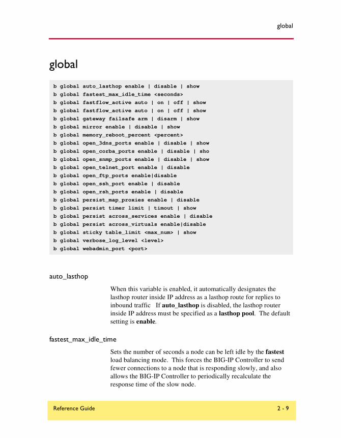
global
global
auto_lasthop
When this variable is enabled, it automatically designates the lasthop router inside IP address as a lasthop route for replies to inbound traffic If auto_lasthop is disabled, the lasthop router inside IP address must be specified as a lasthop pool. The default setting is enable.
fastest_max_idle_time
Sets the number of seconds a node can be left idle by the fastest load balancing mode. This forces the BIG-IP Controller to send fewer connections to a node that is responding slowly, and also allows the BIG-IP Controller to periodically recalculate the response time of the slow node.
b global auto_lasthop enable | disable | show
b global fastest_max_idle_time <seconds>
b global fastflow_active auto | on | off | show
b global fastflow_active auto | on | off | show
b global gateway failsafe arm | disarm | show
b global mirror enable | disable | show
b global memory_reboot_percent <percent>
b global open_3dns_ports enable | disable | show
b global open_corba_ports enable | disable | sho
b global open_snmp_ports enable | disable | show
b global open_telnet_port enable | disable
b global open_ftp_ports enable|disable
b global open_ssh_port enable | disable
b global open_rsh_ports enable | disable
b global persist_map_proxies enable | disable
b global persist timer limit | timout | show
b global persist across_services enable | disable
b global persist across_virtuals enable|disable
b global sticky table_limit <max_num> | show
b global verbose_log_level <level>
b global webadmin_port <port>
Reference Guide 2 - 9

Chapter 2: bigpipe Command Reference
fastflow_active
You can use this variable to control additional enhancements that speed packet flow for TCP connections when the packets are not fragmented. In most configurations these software enhancements are automatically turned on and do not require any additional configuration.
However, you may want to turn off these enhancements for individual virtual servers that use IPFW rate filters. With the speed enhancements on, IPFW only examines the first SYN packet in any given connection. If you want to filter all packets, you should turn the speed enhancements off. To do this, you first set the global state of the system on, and then you turn the feature off for individual virtual servers that use IPFW rate filtering. You can also change the settings for these enhancements from the command line or in the Configuration utility.
There are three global states you can set with fastflow_active. The default state is auto. The global states are:off
auto
on
The additional speed enhancements are globally disabled if the sysctl variable fastflow_active is off or if fastflow_active is set to auto and an IPFW rate filter exists in the configuration.
To provide the benefits of software acceleration for virtual servers that do not use rate filtering and turn off software acceleration for virtual servers that use IPFW rate filtering, you can set the sysctl variable fastflow_active to on with the following command:sysctl -w fastflow_active on
After you set the sysctl variable, use the following bigpipe command to disable software acceleration for virtual servers that use IPFW rate filtering:b virtual <ip>:<port> accelerate disable
gateway
Turns the gateway fail-safe feature on and off. This command is supported only for redundant systems.
2 - 10 BIG-IP® Controller 4.0

global
The typical use of gateway fail-safe is a setup where active and standby BIG-IP Controllers use different routers as gateways to the internet. Fail-over is triggered if the gateway for the active controller is unreachable.
To arm fail-safe on the gateway, enter the following command: b global gateway failsafe arm
To disarm fail-safe on the gateway, enter the following command: b global gateway failsafe disarm
To see the current fail-safe status for the gateway, enter the following command: b global gateway failsafe show
For more information about configuring gateway fail-safe, see Health monitors, on page 1-120.
mirror
Enables mirroring functions globally for the BIG-IP Controller. The mirror feature duplicates the active controller’s real-time connection or persistence information state on the standby controller for smooth transition to the inactive controller at failover. The default setting is enabled.
memory_reboot_percent
The value you type, 80 or higher, is the percentage of memory that is in use before the BIG-IP Controller automatically reboots. The default value for this variable is 0, which is disabled. The minimum value for this variable is 80, or 80 percent of the total physical memory on the controller.
open_3dns_ports
This variable is required only when running one or more separate 3-DNS Controllers in the network. It does not apply to running the 3-DNS software module on the BIG-IP Controller itself. The variable is disabled on the BIG-IP Controller when the 3-DNS Controller is not present in the network configuration. (See the 3-DNS Administrator Guide for more information.)
Reference Guide 2 - 11

Chapter 2: bigpipe Command Reference
open_corba_ports
This variable enables and disables the CORBA ports, which allow administrative CORBA connections. The default setting is disabled.
open_snmp_ports
This variable enables and disables the SNMP ports, which allow administrative SNMP connections. The default setting is disabled.
open_telnet_port
This variable enables or disables ports for Telnet access, and the default setting is disable.
The following command sets this variable to open the Telnet port (23) to allow administrative Telnet connections. This is useful for BIG-IP Controllers that do not support encrypted communications, or for a controller that needs to communicate with 3-DNS Controllers that do not support encrypted communications.
The following command opens the Telnet port.
b global open_telnet_port enable
The following command closes the Telnet port.b global open_telnet_port disable
open_ftp_ports
This variable enables or disables ports for FTP access, and the default setting is disable.
The following command open the FTP ports (20 and 21) to allow administrative FTP connections, which is useful for BIG-IP Controllers that do not support encrypted communications.b global open_ftp_ports enable
The following command closes FTP ports.b global open_ftp_ports disable
2 - 12 BIG-IP® Controller 4.0

global
open_ssh_por
This variable enables or disables ports for SSH access on BIG-IP Controllers that support encrypted communication. The default setting is enable.
The following command opens the SSH port (22) to allow encrypted administrative connections. b global open_ssh_port enable
The following command closes the SSH port.b global open_ssh_port disable
open_rsh_ports
This variable enables or disables ports for RSH access, and it is useful for BIG-IP Controllers that do not support encrypted communications, or for connecting to 3-DNS Controllers that do not support encrypted communication. The default setting is disable.
The following command opens the RSH ports (512, 513, and 514) to allow RSH connections.b global open_rsh_ports enable
The following command closes RSH ports.b global open_rsh_ports disable
persist map_proxies
The default setting for the map proxies for the persistence variable is enable. The AOL proxy addresses are hard-coded in this release. This enables you to use client IP address persistence with a simple persist mask, but forces all AOL clients to persist to the same server. All AOL clients will persist to the node that was picked for the first AOL client connection received.
The class B networks, 195.93 and 205.188, are mapped to 152.163 for persistence. For example, client 195.93.3.4 would map to 152.63.3.4 for persistence records only. This mapping is done prior to applying the persist mask. Use bigpipe pool persist dump to verify that the mapping is working.
Reference Guide 2 - 13

Chapter 2: bigpipe Command Reference
We recommend that in addition to setting this sysctl variable, you set a persist mask of 255.255.0.0 so that all the AOL addresses map to a common address. For example, Table 2.2 is an example of how setting this variable and a persist mask of 255.255.0.0 would map a sample set of client addresses.
persist timer
The following command forces the persistent connection timer to reset on each packet for persistent sessions. This is the default value.
b global persist timer limit
The following command resets the timer only when the persistent connection is initiated.
b global persist timer timout
Note
For SSL persistence, the timer is always reset on each packet.
Sample Client Address Persist Address
152.44.12.3 195.93.0.0
152.2.99.7 195.93.0.0
170.11.19.22 195.93.0.0
202.67.34.11 195.93.0.0
205.188.11.2 195.93.0.0
208.33.23.4 208.33.0.0 (non AOL address is not mapped)
Table 2.2 Address mapping of sample clients
2 - 14 BIG-IP® Controller 4.0

global
persist across_services
When this variable is enabled, all simple persistence connections from a client IP address that go to the same virtual address also go to the same node (matches the client address and the virtual IP address but not the virtual port).
The default setting for this variable is disabled.
persist across_virtuals
When this variable is enabled, all simple persistent connections from the same client IP address are sent to the same node (matches the client IP address but not the virtual address or virtual port the client is using). The default setting for this variable is disabled.
sticky table_limit
This is the maximum number of sticky entries allowed to accumulate on the BIG-IP Controller when using destination address affinity (sticky persistence). When the maximum value is reached, the BIG-IP Controller stops accumulating sticky entries. The default value for this entry is 2048.
verbose_log_leve
This variable set logging levels for both TCP and UDP traffic. Each log level is identified by a level number used in place of the <level> parameter.
The following command turns on port denial logging for both TCP and UDP traffic. This logs TCP and UDP port denials to the virtual server address and the BIG-IP Controller address.verbose_log_level=15
The following command turns logging off altogether:verbose_log_level=0
Setting log levels only for TCP traffic
The following command turns on only TCP port denial logging, which logs TCP port denials to the BIG-IP Controller address.verbose_log_level=2
Reference Guide 2 - 15

Chapter 2: bigpipe Command Reference
The following command turns on virtual TCP port denial logging, which logs TCP port denials to the virtual server address.verbose_log_level=8
Setting log levels for UDP traffic
The following command turns on only UDP port denial logging, which logs UDP port denials to the BIG-IP Controller address.verbose_log_level=1
The following command turns on only virtual UDP port denial logging, which logs UDP port denials to the virtual server address.verbose_log_level=4
webadmin_port
Specifies the port number used for administrative web access. The default port for web administration is port 443.
2 - 16 BIG-IP® Controller 4.0

-h and -help
-h and -help
Displays the bigpipe command syntax or usage text for all current commands.
Note
More detailed man pages are available for some individual bigpipe commands. To display detailed online help for the bigpipe command, type: man bigpipe.
b [-h | -help ]
Reference Guide 2 - 17

Chapter 2: bigpipe Command Reference
interface
Displays names of installed network interface cards and allows you to set properties for each network interface card.
Setting the media type
The media type may be set to the specific media type for the interface card or it may be set to auto for auto detection. If the media type is set is set to auto and the card does not support auto detection, the default type for that interface will be used, for example 1000BaseTX.
Setting the duplex mode
Duplex mode may be set to full or half duplex. If the media type does not allow duplex mode to be set, this will be indicated by an onscreen message. If media type is set to auto, or if setting duplex mode is not supported, the duplex setting will not be saved to bigip.conf.
b interface <if_name> media <media_type>|show
b interface <if_name> duplex full|half|auto|show
b interface [<if_name>] show
2 - 18 BIG-IP® Controller 4.0
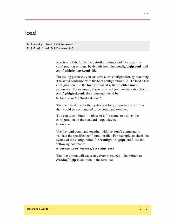
load
load
Resets all of the BIG-IP Controller settings and then loads the configuration settings, by default from the /config/bigip.conf and /config/bigip_base.conf file.
For testing purposes, you can save a test configuration by renaming it to avoid confusion with the boot configuration file. To load a test configuration, use the load command with the <filename> parameter. For example, if you renamed your configuration file to /config/bigtest.conf, the command would be:b load /config/bigtest.conf
The command checks the syntax and logic, reporting any errors that would be encountered if the command executed.
You can type b load - in place of a file name, to display the configuration on the standard output device.b save -
Use the load command together with the verify command to validate the specified configuration file. For example, to check the syntax of the configuration file /config/altbigpipe.conf, use the following command:b verify load /config/altbigip.conf
The -log option will cause any error messages to be written to /var/log/bigip in addition to the terminal.
b [verify] load [<filename>|-]
b [-log] load [<filename>|-]
Reference Guide 2 - 19
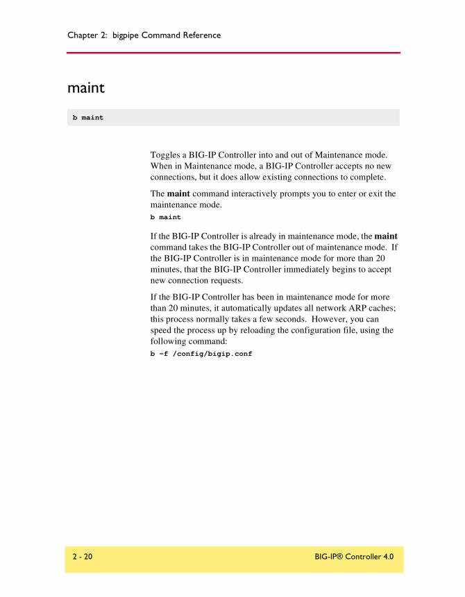
Chapter 2: bigpipe Command Reference
maint
Toggles a BIG-IP Controller into and out of Maintenance mode. When in Maintenance mode, a BIG-IP Controller accepts no new connections, but it does allow existing connections to complete.
The maint command interactively prompts you to enter or exit the maintenance mode.b maint
If the BIG-IP Controller is already in maintenance mode, the maint command takes the BIG-IP Controller out of maintenance mode. If the BIG-IP Controller is in maintenance mode for more than 20 minutes, that the BIG-IP Controller immediately begins to accept new connection requests.
If the BIG-IP Controller has been in maintenance mode for more than 20 minutes, it automatically updates all network ARP caches; this process normally takes a few seconds. However, you can speed the process up by reloading the configuration file, using the following command:b -f /config/bigip.conf
b maint
2 - 20 BIG-IP® Controller 4.0

makecookie
makecookie
Generates a cookie string with encoding automatically added for cookie persistence Passive mode:b makecookie <server_address:service> [ > <file>]
This command prints a cookie template similar to the templates shown in Figure 2.2 and Figure 2.3.
To create your cookie using the sample string above, simply enter the actual pool names and the desired expiration date and time.
b makecookie <ip_addr:service>
Set-Cookie:BIGipServer[poolname]=336268299.20480.0000; path=/
Figure 2.2 Sample cookie template
Set-Cookie:BIGipServer[poolname]=336268299.20480.0000; expires=Sat, 01-Jan-2000 00:00:00 GMT; path=/
Figure 2.3 Sample cookie template with additional information
Reference Guide 2 - 21

Chapter 2: bigpipe Command Reference
merge
Use the merge command to load the BIG-IP Controller configuration from <file_name> without resetting the current configuration.
b [-log] merge [<file_name>]
2 - 22 BIG-IP® Controller 4.0

monitor
monitor
Defines a health monitor. A health monitor is a configuration object that defines how and at what intervals a node is pinged to determine if it is up or down. Once a monitor is defined, instances of the monitor are created for a node or nodes, one instance per node, using the bigpipe node command.
Showing, disabling, and deleting monitors
There are monitor commands for showing, disabling, and deleting monitors.
To show monitors
You can display a selected monitor or all monitors using the bigpipe monitor show command:b monitor <name> show
b monitor show all
To disable a monitor or monitor instance
All monitors and monitors instances are enabled by default. You can disable a selected monitor or monitor instance, which effectively removes the monitor or instance from service. To disable a monitor and all of its instances, use the bigpipe monitor <name> disable command: b monitor <name> disable
b monitor <monitor_name> {use <monitor_template> [<attr> <attr_value>]... }
b monitor show [all]
b monitor dump [all]
b monitor <name> show
b monitor <name> delete
b monitor <name> enable | disable
b monitor instance <ip>:<service> enable | disable
b monitor instance <ip> enable | disable
Reference Guide 2 - 23
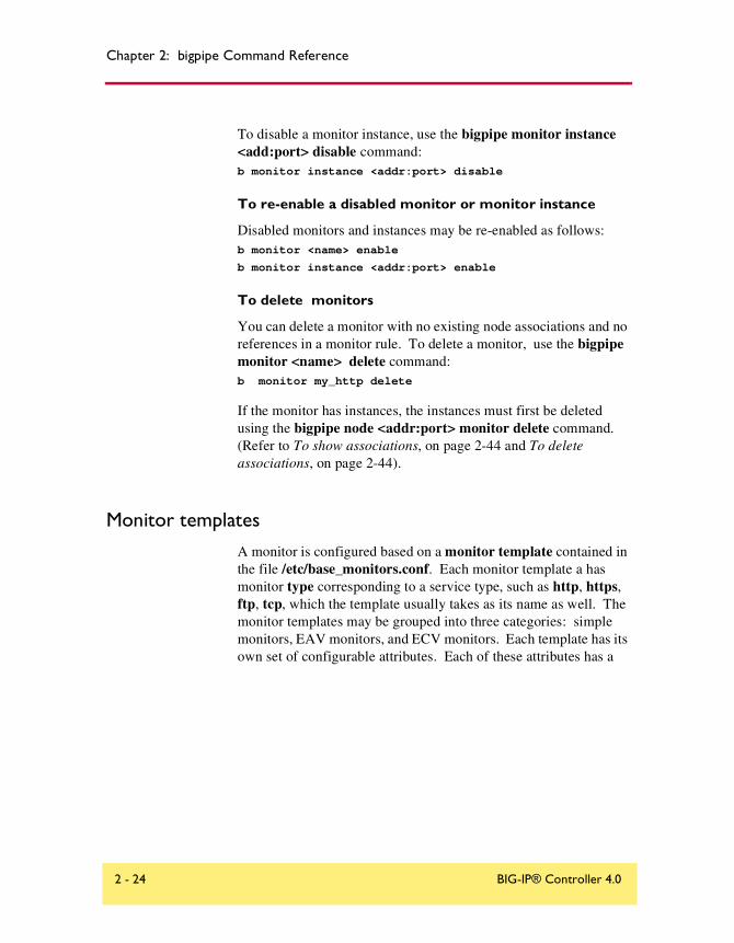
Chapter 2: bigpipe Command Reference
To disable a monitor instance, use the bigpipe monitor instance <add:port> disable command:b monitor instance <addr:port> disable
To re-enable a disabled monitor or monitor instance
Disabled monitors and instances may be re-enabled as follows:b monitor <name> enable
b monitor instance <addr:port> enable
To delete monitors
You can delete a monitor with no existing node associations and no references in a monitor rule. To delete a monitor, use the bigpipe monitor <name> delete command:b monitor my_http delete
If the monitor has instances, the instances must first be deleted using the bigpipe node <addr:port> monitor delete command. (Refer to To show associations, on page 2-44 and To delete associations, on page 2-44).
Monitor templates
A monitor is configured based on a monitor template contained in the file /etc/base_monitors.conf. Each monitor template a has monitor type corresponding to a service type, such as http, https, ftp, tcp, which the template usually takes as its name as well. The monitor templates may be grouped into three categories: simple monitors, EAV monitors, and ECV monitors. Each template has its own set of configurable attributes. Each of these attributes has a
2 - 24 BIG-IP® Controller 4.0
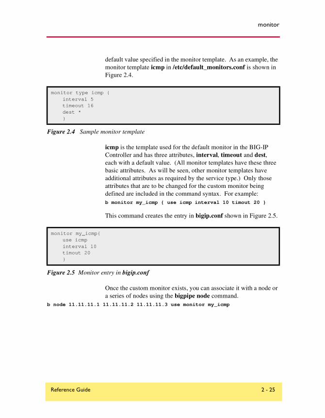
monitor
default value specified in the monitor template. As an example, the monitor template icmp in /etc/default_monitors.conf is shown in Figure 2.4.
icmp is the template used for the default monitor in the BIG-IP Controller and has three attributes, interval, timeout and dest, each with a default value. (All monitor templates have these three basic attributes. As will be seen, other monitor templates have additional attributes as required by the service type.) Only those attributes that are to be changed for the custom monitor being defined are included in the command syntax. For example:b monitor my_icmp { use icmp interval 10 timout 20 }
This command creates the entry in bigip.conf shown in Figure 2.5.
Once the custom monitor exists, you can associate it with a node or a series of nodes using the bigpipe node command.
b node 11.11.11.1 11.11.11.2 11.11.11.3 use monitor my_icmp
monitor type icmp {interval 5timeout 16dest *}
Figure 2.4 Sample monitor template
monitor my_icmp{use icmpinterval 10timout 20}
Figure 2.5 Monitor entry in bigip.conf
Reference Guide 2 - 25

Chapter 2: bigpipe Command Reference
Monitor template attributes
Table 2.3 lists the monitor templates and shows the template-specific attribute sets for each.
Name/Type Template-Specific Attribute Set
icmp none
tcp_echo transparent (optional)
tcp send ""recv ""transparent (optional)
reverse (optional)
http username ""password ""send "GET /index.html"recv ""get (optional)url (optional)transparent (optional)reverse (optional)
https username ""password ""send "GET /index.html"recv ""get (optional)url (optional)transparent (optionalreverse (optional
external run ""args ""
ftp username "anonymous"password "bigip1@internal"get "/README"url (optional)
Table 2.3 The monitor templates
2 - 26 BIG-IP® Controller 4.0

monitor
Table 2.4 defines the attributes used in the templates.
nntp username ""password ""newsgroup "local"
pop3 username ""password ""
smtp domain "bigip1@internal"
imap username ""password ""folder "INBOX"message_num (optional)
radius username "username"password "password"secret "12345678"
ldap base "o=Org, c=US"filter "sn=Doe"
sql username ""password ""database ""
https_443 dest *:443
Attribute Definition
interval <seconds> Ping frequency time interval in seconds.
timeout <seconds> Ping timeout in seconds.
Table 2.4 Monitor attributes
Name/Type Template-Specific Attribute Set
Table 2.3 The monitor templates
Reference Guide 2 - 27
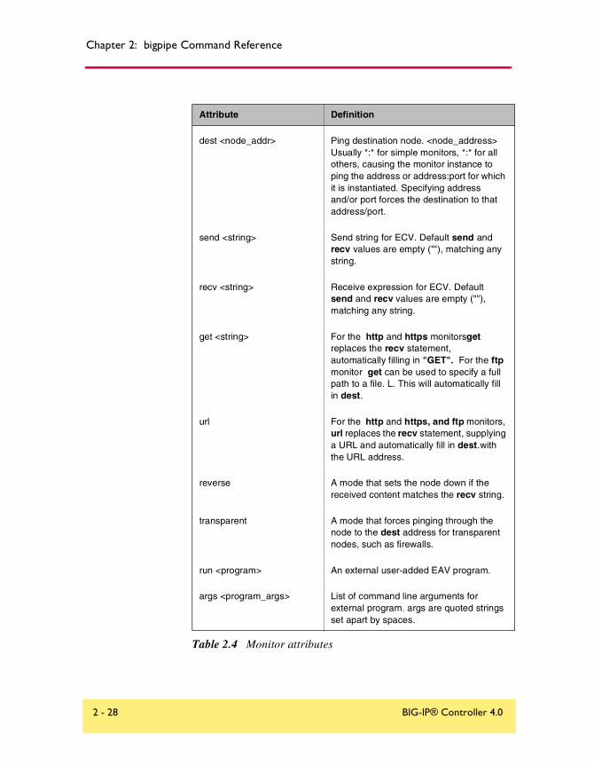
Chapter 2: bigpipe Command Reference
dest <node_addr> Ping destination node. <node_address> Usually *:* for simple monitors, *:* for all others, causing the monitor instance to ping the address or address:port for which it is instantiated. Specifying address and/or port forces the destination to that address/port.
send <string> Send string for ECV. Default send and recv values are empty (""), matching any string.
recv <string> Receive expression for ECV. Default send and recv values are empty (""), matching any string.
get <string> For the http and https monitorsget replaces the recv statement, automatically filling in "GET". For the ftp monitor get can be used to specify a full path to a file. L. This will automatically fill in dest.
url For the http and https, and ftp monitors, url replaces the recv statement, supplying a URL and automatically fill in dest.with the URL address.
reverse A mode that sets the node down if the received content matches the recv string.
transparent A mode that forces pinging through the node to the dest address for transparent nodes, such as firewalls.
run <program> An external user-added EAV program.
args <program_args> List of command line arguments for external program. args are quoted strings set apart by spaces.
Attribute Definition
Table 2.4 Monitor attributes
2 - 28 BIG-IP® Controller 4.0

monitor
Send, receive and get statementsThe ECV monitor templates http, https, and tcp have the attributes send and recv for the send string and receive expression, respectively.
username <username> Username for services with password security. For ldap this is a distinguished name (an LDAP-format username).
password <password> Password for services with password security.
newsgroup <newsgroup> Newsgroup, for type nntp EAV checking only
database <database> Database name, for type sql EAV checking only.
domain <domain_name> Domain name, for type smtp EAV checking only
secret Shared secret for radius EAV checking only.
folder Folder name for imap EAV checking only.
message_num optional message number for imap EAV checking only
base Starting place in the LDAP hierarchy from which to begin the query, for ldap EAV checking only.
filter LDAP- format key of what is to be searched for, for ldap EAV checking only.
Attribute Definition
Table 2.4 Monitor attributes
Reference Guide 2 - 29

Chapter 2: bigpipe Command Reference
The most common send string is “GET /” which simply retrieves a default HTML page for a web site. To retrieve a specific page from a web site, simply enter a fully qualified path name:"GET /www/support/customer_info_form.html"
The receive expression is the text string the monitor looks for in the returned resource. The most common receive expressions contain a text string that would be included in a particular HTML page on your site. The text string can be regular text, HTML tags, or image names.
The sample receive expression below searches for a standard HTML tag."<HEAD>"
You can also use the default null recv value "". In this case, any content retrieved is considered a match. If both send and recv are left empty, only a simple connection check is performed.
For http and ftp, the special attributes get or url may be used in place of send and recv statements. get takes the full path to the file as a value and automatically fills in the dest value with the address the path resolves to. The following two statements are equivalent:send "GET/"
get "/"
url takes the URL as a value and automatically fills in the dest value with the address the URL resolves to. The URL is then resolved to supply the dest address automatically. The third statement below is equivalent to the first two combined:dest 198.192.112.13:22
get "/"
url "ftp://www.my_domain.com/"
Transparent and reverse modes
The ECV monitors have optional keywords transparent and reverse. (transparent is also used by the simple monitor template tcp_echo.) The normal and default mode for a monitor is to ping
2 - 30 BIG-IP® Controller 4.0

monitor
the dest node by an unspecified route and to mark the node up if the test is successful. There are two other modes, transparent and reverse.
In transparent mode, the monitor is forced to ping through the node it is associated with, usually a firewall, to the dest node. (In other words, if there are two firewalls in a load balancing pool, the destination node will always be pinged through the one specified and not through the one picked by the load balancing method.) In this way, the transparent node is tested as well.
In reverse mode, the monitor marks the node down when the test is successful. For example, if the content on your web site home page is dynamic and changes frequently, you may want to set up a reverse ECV service check that looks for the string "Error". A match for this string would mean that the web server was down. Transparent mode can also be used with the monitor template tcp_echo.
Testing SQL service checks
SQL service checks may require manually testing before being implemented in a monitor, as follows:cd /usr/local/lib/pingers
./tdslogin 192.168.1.1 1433 mydata user1 mypass1
Replace the IP address, port, database, user, and password in this example with your own information.
You should receive the message: Login succeeded!
If you receive the connection refused message, verify that the IP and port are correct.
If you are still having trouble, you should verify that you can log in using another tool. For example, if you have Microsoft NT SQL Server version 6.5, there is a client program ISQL/w included with the SQL software. This client program performs simple logins to
Reference Guide 2 - 31

Chapter 2: bigpipe Command Reference
SQL servers. Use this program to test whether you can login using the ISQL/w program before attempting logins from the BIG-IP Controller.
On the SQL Server, you can run the SQL Enterprise Manager to add logins. When first entering the SQL Enterprise Manager, you may be prompted for the SQL server to manage.
You can register servers by entering the machine name, user name, and password. If these names are correct, the server will be registered and you will be able to click an icon for the server. When you expand the subtree for the server, there will be an icon for Logins.
Underneath this subtree, you can find the SQL logins. Here, you can change passwords or add new logins by right-clicking the Logins icon. Click this icon to open an option to Add login. After you open this option, enter the user name and password for the new login, as well as which databases the login is allowed to access. You must grant the test account access to the database you specify in the EAV configuration.
Running user-added EAVs
You may add your own pingers to those contained in /user/local/lib/pingers. For running these added programs, the monitor template external is used. The program is specified as the value or the attribute run. The monitor will look for the run program in /user/local/lib/pingers. If the program resides elsewhere, a fully qualified pathname must be entered. Any command line arguments to be used with the program are entered as args values. For example, suppose the program my_pinger is to be run with a -q option, so that it would be entered on a command line as follows:my_pinger -q
This monitor might be specified as follows:monitor custom {use external run "my_pinger" args "-q"}
2 - 32 BIG-IP® Controller 4.0

monitor
Alternatively, you may pass arguments to the external monitor as environment variables. For example, you might want to enter this command:/var/my_pinger /www/test_files/first_test
This could be specified in the conventional manner:b monitor custom { use external run "/var/my_pinger" args
"www/test_files/first_test" }
It could also be specified in this way:b monitor custom { use external run "/var/my_pinger" DIRECTORY "
"www/test_files" FILE "first_test" }
This defines the monitor as shown in Figure 2.6.
The custom monitor requirements free the monitor definition from the rigidity of a strictly ordered command line entry. The arguments are now order-independent and may be used or ignored by the external executable.
Node and port aliasing
Usually the health of a node is checked by pinging that node. For this reason the dest attribute is usually set to "*" or "*:*". This will cause the instance of the monitor created for that node to take the address and port of the node as its destination. Suppose, for example, that the following command were entered:
b node 11.11.11.1:80 11.11.11.2:80 11.11.11.3:80 use monitor my_tcp
Assuming the dest attribute on the monitor was left at the default *:*, this will create three monitor instances with the following destinations:
monitor custom { use externalrun "/var/my_pinger"DIRECTORY "www/test_files" FILE "first_test" }
Figure 2.6 Monitor definition for external pinger
Reference Guide 2 - 33

Chapter 2: bigpipe Command Reference
11.11.11.1:80
11.11.11.2:80
11.11.11.3:80
An explicit dest value is used only to force the instance destination to a specific address or port which may not be that of the node. This will cause the monitor to ping to that forced destination by an unspecified path. (If it is necessary to ping the forced destination through the node, as when a router address is checked through a firewall, then the transparent attribute is used. This applies only to the ECV monitors and to tcp_echo.) Thus, for the example above, an explicit dest value of *:443, would create three instances of the monitor with the following destinations:11.11.11.1:443
11.11.11.2:443
11.11.11.3:443
This is referred to as port aliasing. The node itself can also be aliased by assigning an explicit node address to dest. For example, if dest were set to 11.11.11.5:*, the monitor instances created for nodes 11.11.11.1:80, 11.11.11.2:80, 11.11.11.3:80 and 11.11.11.4:80 would have the following destinations:11.11.11.5:80
11.11.11.5:80
11.11.11.5:80
Logical grouping
In the example above, only one monitor, my_tcp, has been associated with the nodes. You may associate more than one monitor. This creates a rule, and the node will be marked down if the rule evaluates to false. The most common example is use of an HTTP monitor and an HTTPS monitor:
node 11.11.11.1:80 11.11.11.2:80 11.11.11.3:80 use monitor my_http and my_https
Logical groupings must be logical, which means that the monitors themselves must be configured with the grouping in mind. In this case, monitor my_http would need to have a dest value of *:* and monitor my_https would need to have a dest value of *:443. This would cause the my_http monitor instances to ping the port 80’s of
2 - 34 BIG-IP® Controller 4.0

monitor
each address and the my_https monitor instances to ping the port 443’s of each address. If the dest values of both monitors were set to *:*, then both monitor instances would try to ping port 80. This would both defeat the purpose of the HTTPS monitor and cause an automatic failure, since two monitors would be trying to ping the same address and port simultaneously.
Using wildcards to specify node addresses and ports
The wildcard * can be used to specify node addresses and ports. For example, if a monitor instance of my_tcp_echo were to be created for port 80 on all nodes being load balanced by the BIG-IP, this could be done as follows:b node *:80 use monitor my_tcp_echo
load the BIG-IP Controller configuration from <file_name> without resetting the current configuration.
Reference Guide 2 - 35
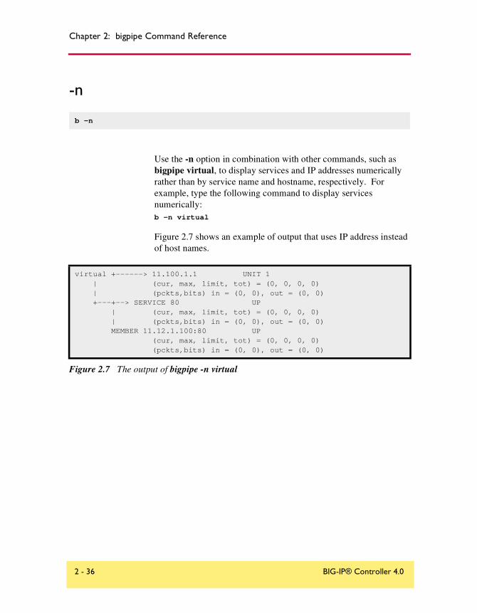
Chapter 2: bigpipe Command Reference
-n
Use the -n option in combination with other commands, such as bigpipe virtual, to display services and IP addresses numerically rather than by service name and hostname, respectively. For example, type the following command to display services numerically:b -n virtual
Figure 2.7 shows an example of output that uses IP address instead of host names.
b -n
virtual +------> 11.100.1.1 UNIT 1 | (cur, max, limit, tot) = (0, 0, 0, 0) | (pckts,bits) in = (0, 0), out = (0, 0) +---+--> SERVICE 80 UP | (cur, max, limit, tot) = (0, 0, 0, 0) | (pckts,bits) in = (0, 0), out = (0, 0) MEMBER 11.12.1.100:80 UP (cur, max, limit, tot) = (0, 0, 0, 0) (pckts,bits) in = (0, 0), out = (0, 0)
Figure 2.7 The output of bigpipe -n virtual
2 - 36 BIG-IP® Controller 4.0

nat
nat
Defines an IP address, routable on the external network, that a node can use to initiate connections to hosts on the external network and receive direct connections from clients on the external network. The NAT (Network Address Translation) command defines a mapping between the IP address of a server behind the BIG-IP Controller <orig_addr> and an unused routable address on the network in front of the BIG-IP Controller <trans_addr>.
Defining a NAT
A NAT definition maps the IP address of a node <orig_addr> to a routable address on the external interface <trans_addr>, and can include an optional interface and netmask specification.
To define a NAT
Use the following syntax to define a NAT:b nat <orig_addr> to <trans_addr> [vlan <vlan_name> disable | enable] [unit
<unit ID>]
To delete NATs
Use the following syntax to delete one or more NATs from the system:b nat <orig_addr> [...<orig_addr>] delete
b nat <orig_addr> to <trans_addr> [unit <unit ID>]
b nat <orig_addr> [...<orig_addr>] delete
b nat [<trans_addr> [...<trans_addr>] ] show | delete
b nat [<orig_addr> [...<orig_addr>] ] show | delete
b nat [<orig_addr>...] stats reset
b nat <orig_addr> vlans <vlan_list> enable | disable
b nat <orig_addr> vlans delete all
b nat <orig_addr> vlans show
b nat <orig_addr> arp [enable|disable|show]
Reference Guide 2 - 37

Chapter 2: bigpipe Command Reference
To display status of NATs
Use the following command to display the status of all NATs included in the configuration:b nat show
See Figure 2.8 for the output when you display the status of a NAT. Use the following syntax to display the status of one or more selected NATs:b nat <orig_addr> [...<orig_addr>] show
To reset statistics for a NAT
Use this command to reset the statistics for an individual NAT:b nat [<orig_addr>] stats reset
Use the following command to reset the statistics for all NATs:b nat stats reset
Additional Restrictions
The nat command has the following additional restrictions:
◆ The IP address defined in the <orig_addr> parameter must be routable to a specific server behind the BIG-IP Controller.
◆ You must delete a NAT before you can redefine it.
◆ The interface for a NAT may only be configured when the NAT is first defined.
NAT { 10.10.10.3 to 9.9.9.9 } (pckts,bits) in = (0, 0), out = (0, 0)
NAT { 10.10.10.4 to 12.12.12.12 netmask 255.255.255.0 broadcast 12.12.12.255 } (pckts,bits) in = (0, 0), out = (0, 0)
Figure 2.8 Output when you display the status of a NAT
2 - 38 BIG-IP® Controller 4.0

nat
Disabling VLANs for a NAT
A NAT is mapped by default to all VLANs on the internal and external networks of the BIG-IP Controller. Any VLANs to which the NAT is not to be mapped must be explicitly disabled using the vlan <vlan_name> disable syntax.
Viewing a controller’s unit ID number
You can use the unit <unit ID> parameter to specify the controller to which this NAT applies in an active-active redundant system.
Disabling ARP requests
By default, the BIG-IP controller responds to ARP requests for the NAT address and sends a gratuitous ARP request for router table update. If you want to disable the NAT address for ARP requests, you must specify arp disable.
Reference Guide 2 - 39

Chapter 2: bigpipe Command Reference
node
Displays information about nodes and allows you to set properties for nodes, and node addresses. Nodes may be identified using wildcard notation. Thus * represents all nodes on the network, *.80 represents all port 80 nodes, 11.11.11.1:* represents all nodes with address 11.11.11.1.
To enable and disable nodes and node addresses
A node must be enabled in order to accept traffic. When a node is disabled, it will allow existing connections to time out and accept new connections only if they belong to an existing session. (In this way a disabled node differs from a node that is set down. The down node will allow existing connections to time out but will accept no new connections.)
To enable a node address, use the node command with a node address and the enable option:b node 192.168.21.1 enable
To disable a node address, use the node command with the disable option: b node 192.168.21.1 disable
To enable one or more node addresses, use the node command with a node address and port, and the enable option:b node 192.168.21.1:80 enable
b node <node_ip>[:<service>]... enable | disable
b node <node_ip>[:<service>... show
b node <node_ip>[:<service>]... limit <max_conn>
b node [<node_ip>:<service>]... stats reset
b node <node_ip>[:service] up | down
b node <node_ip>[:<service>] monitor use <monitor_name> [and <monitor_name]...
b node [<node_ip>[:<service>]] monitor show | delete
b node <node_ip>[<node_ip>]... virtual | actual
2 - 40 BIG-IP® Controller 4.0

node
To disable one or more node addresses, use the node command with the disable option: b node 192.168.21.1:80 disable
Marking nodes and node ports up and down
A node must be marked up in order to accept traffic. When a node is marked down it will allow existing connections to time out but will accept no new connections.
To mark a node address down, use the node command with a node address and the down option. (Note that marking a node down prevents the node from accepting new connections. Existing connections are allowed to complete.)b node 192.168.21.1 down
To mark a node address up, use the node command with the up option: b node 192.168.21.1 up
To mark a service down, use the node command with a node address and port, and the down option. (Note that marking a port down prevents the port from accepting new connections. Existing connections are allowed to complete.)b node 192.168.21.1:80 down
To mark a port up, use the node command with up option: b node 192.168.21.1:80 up
Setting connection limits for nodes and node addresses
Use the following command to set the maximum number of concurrent connections allowed on a node:
b node <node_ip>[:<service>][...<node_ip>[:<service>]] \limit <max conn>
Note that to remove a connection limit, you also issue the preceding command, but set the <max conn> variable to 0 (zero). For example:b node 192.168.21.1:80 limit 0
Reference Guide 2 - 41

Chapter 2: bigpipe Command Reference
The following example shows how to set the maximum number of concurrent connections to 100 for a list of node addresses:b node 192.168.21.1 192.168.21.1 192.168.21.1 limit 100
To remove a connection limit, you also issue this command, but set the <max conn> variable to 0 (zero).
Displaying status of all nodes
The following command displays the status of all nodes defined on the controller.b node show
When you issue the node show command, the BIG-IP Controller displays the node status (up or down, or unchecked), and a node summary of connection statistics, which is further broken down to show statistics by port. The report shows the following information:
• current number of connections
• total number of connections made to the node since last boot
• maximum number of concurrent connections since the last boot
• concurrent connection limit on the node
• total number of connections made to the node since last boot
• total number of inbound and outbound packets and bits
Figure 2.9 shows the output of this command.
bigpipe node 192.168.200.50:20NODE 192.168.200.50 UP | (cur, max, limit, tot) = (0, 0, 0, 0)| (pckts,bits) in = (0, 0), out = (0, 0)+- PORT 20 UP (cur, max, limit, tot) = (0, 0, 0, 0) (pckts,bits) in = (0, 0), out = (0, 0)
Figure 2.9 Node status and statistics
2 - 42 BIG-IP® Controller 4.0

node
Displaying the status of individual nodes and node addresses
Use this command to display status and statistical information for one or more node addresses:b node 192.168.21.1 show
The command reads the status of each node address, the number of current connections, total connections, and connections allowed, and the number of cumulative packets and bits sent and received.
Use the following command to display status and statistical information for one or more specific nodes:b node 192.168.21.1:80 show
Resetting statistics for a node
Use the following command to reset the statistics for an individual node address:b node [<node_ip>:<service>] stats reset
Associating a health monitor with a node
Use the following command to associate a health monitor with a node:node <node> monitor use <monitor>
A monitor can be placed on multiple nodes and a node can have multiple monitors placed on it. To place a monitor on multiple nodes:node <node_list> monitor use <monitor>
To add multiple monitors to a node
To place multiple monitors on a node:node <node> monitor use <monitor1> and <monitor2>...
For more information on using the node command with health monitors, refer to monitor, on page 2-23.
Reference Guide 2 - 43

Chapter 2: bigpipe Command Reference
To show associations
You can display a selected node association or all node associations using the bigpipe node monitor show command:b node monitor show
b node <addr:port> monitor show
To delete associations
You can delete a selected node association or all node associations using the bigpipe node monitor delete command:b node monitor delete
b node <addr:port> monitor delete
In deleting specific monitor instances, it is important to consider how the association was created and therefore how it exists in the /config/bigip.conf file. For example, if an association exists through aliasing, the delete cannot be performed on the alias, but instead on the node that was actually associated. Or, if a monitor instance was created using wildcard address or port, the wildcard must be deleted.
For example, if multiple associations were created by entering b node *:80 monitor use my_tcp_echo, you would delete it by typing:b node *:80 monitor delete
2 - 44 BIG-IP® Controller 4.0

pool
pool
Use the pool command to create, delete, modify, or display the pool definitions on the BIG-IP Controller. Use pools to group members together with a common load balancing mode and persistence mode. For additional information about configuring pools, see the BIG-IP Administrator Guide, Working with Intelligent Traffic Control.
Creating a pool
To create a pool use the following syntax:b pool <pool_name> {lb_method <lb_method_specification> [persist_mode
<persist_mode_specification>] <member_definition>... member <member_definition>}
b pool <pool_name> { lb_method <lb_method_specification> <member_definition>
b pool <pool_name> { lb_method <lb_method_specification> persist_mode <persist_mode_specification> <member definition>... }
b pool <pool_name> { lb_method <lb_method_specification> min_active_members <min_value> <member definition>... }
b pool <pool_name> { lb_method <lb_method_specification> <member_definition> fallback <host>
b pool <pool_name> add { <member definition>... }
b pool <pool_name> delete { <member definition>... }
b pool <pool_name> modify { [lb_method <lb_method_specification>] [persist_mode <persist_mode_specification>] <member definition>... }
b pool <pool_name> delete
b pool [<pool_name>] show
b pool <pool_name> lb_method show
b pool <pool_name> persist dump
b pool <pool_name> persist dump mirror
b pool <pool_name> sticky clear
b pool <pool_name> stats reset
Reference Guide 2 - 45

Chapter 2: bigpipe Command Reference
Each of the elements included in the pool command is described in Table 2.6, on page 2-47. You can also find detailed information about setting up persistence with pools in Setting up persistence for a pool, on page 1-22.
Specifying load balancing mode
The load balancing modes are specified as values of the attribute lb_mode. The lb_mode values are shown in Table 2.5.
For more information about the load balancing modes, refer to Proxies, on page 1-73.
Mode Name lb_mode attribute value
Round Robin rr or omit lb_mode specification
Ratioratio
Ratio Member ratio_member
Fastest fastest
Fastest Member fastest_member
Least Connections least_conn
Least Connections Member least_conn_member
Observed observed
Observed Member observed_member
Predictive predictive
Predictive Member predictive_member
Dynamic Ratio dynamic_ratio
Table 2.5 Load balancing modes
2 - 46 BIG-IP® Controller 4.0

pool
Table 2.6 shows additional elements available for the pool command.
Table 2.6 The elements you can use to construct a pool
Deleting a pool
To delete a pool, use the following syntax:b pool <pool_name> delete
All references to a pool must be removed before a pool can be deleted.
Modifying pools
You can use the command line to add or delete members from a pool. You can also modify the load balancing mode for a pool from the command line. To add a new member to a pool use the following syntax:b pool <pool_name> add { 1.2.3.2:telnet }
To delete a member from a pool use the following syntax:b pool <pool_name> delete { 1.2.3.2:telnet }
Pool Element Description
Pool name A string from 1 to 31 characters, for example: new_pool
Member definition member <ip address>:<service> [ratio <value>] [priority <value>]
lb_method_specificaton lb_method [ rr | ratio | fastest | least_conn | predictive | observed | ratio_member | least_conn_member |observed_member | predictive_member | dynamic_ratio ]
min_value minimum number of members that must be active for a priority group to remain active.
persist_mode_specification persist_mode [ cookie | simple | ssl | sticky ]
Reference Guide 2 - 47

Chapter 2: bigpipe Command Reference
Displaying pool statistics
Use the following syntax to display all pools:b pool show
Use the following syntax to display a specific pool:b pool <pool_name> show
Activating HTTP cookie persistence
The following syntax activates HTTP cookie persistenceb pool <pool_name> { <lb_method_specification> persist_mode cookie
cookie_mode passive <member definition> }
Note
The <timeout> value is not used in Passive mode.
Configuring the hash cookie persistence option
If you specify hash mode, the hash mode consistently maps a cookie value to a specific node. When the client returns to the site, the BIG-IP Controller uses the cookie information to return the client to a given node. With this mode, the web server must generate the cookie. The BIG-IP Controller does not create the cookie automatically like it does with Insert mode.
To configure hash cookie persistence
Use the following syntax to configure the hash cookie persistence option:
b pool <pool_name> { <lb_method_specification> persist_mode cookie cookie_mode hash cookie_hash_name <cookie_name> cookie_hash_offset <cookie_value_offset> cookie_hash_length <cookie_value_length> <member definition> }
2 - 48 BIG-IP® Controller 4.0

pool
The <cookie_name>, <cookie_value_offset>, and <cookie_value_length> values are described in Table 2.7.
Activating Insert HTTP cookie persistence
If you specify Insert mode, the BIG-IP Controller inserts a cookie from the server in the header of the HTTP response with information about the server to which the client connects. The cookie is named BIGipServer<pool_name>, and it includes the address and port of the server handling the connection. The expiration date for the cookie is set based on the timeout configured on the BIG-IP Controller.
To activate Insert mode
To activate Insert mode from the command line, use the following syntax:
b pool <pool_name> { <lb_method_specification> persist_mode cookie cookie_mode insert cookie_expiration <timeout> <member definition> }
The <timeout> value for the cookie is written using the following format:<days>d hh:mm:ss
Hash mode values Description
<cookie_name>This is the name of an HTTP cookie being set by a Web site.
<cookie_value_offset> This is the number of bytes in the cookie to skip before calculating the hash value.
<cookie_value_length> This is the number of bytes to use when calculating the hash value.
Table 2.7 The cookie hash mode values
Reference Guide 2 - 49

Chapter 2: bigpipe Command Reference
Activating Rewrite mode cookie persistence
If you specify Rewrite mode, the BIG-IP Controller intercepts a Set-Cookie, named BIGipCookie, sent from the server to the client and overwrites the name and value of the cookie. The new cookie is named BIGipServer<pool_name> and it includes the address and port of the server handling the connection.
To use Rewrite mode, you must set up the cookie created by the server. For Rewrite mode to work, the BIG-IP Controller needs a blank cookie coming from the web server to rewrite. With Apache variants, you can add the cookie to every web page header by adding an entry in the httpd.conf file: Header add Set-Cookie BIGipCookie=00000000000000000000000000000000000000000...
The cookie should contain a total of 120 zeros.
WARNING
For backward compatibility, the blank cookie can contain only 75 zeros. However, cookies of this size do not allow you to use rules and persistence together.
To activate Rewrite mode
The following syntax activates Rewrite mode.b pool <pool_name> { <lb_method_specification> persist_mode cookie
cookie_mode rewrite cookie_expiration <timeout> <member definition> }
The <timeout> value for the cookie is written using the following format:<days>d hh:mm:ss
Activating Passive mode cookie persistence
If you specify Passive mode, the BIG-IP Controller does not insert or search for blank Set-Cookies in the response from the server. It does not try to set up the cookie. In this mode, BIG-IP Controller assumes that the server provides the cookie formatted with the correct node information and timeout.
2 - 50 BIG-IP® Controller 4.0

pool
In order for Passive mode to work, a cookie needs to come from the web server with the appropriate node information in the cookie. With Apache variants, you can add the cookie to every web page header by adding an entry in the httpd.conf file:
Header add Set-Cookie: "BIGipServerMY_POOL=184658624.20480.000; expires=Sat, 19-Aug-2000 19:35:45 GMT; path=/"
In this example, my_pool is the name of the pool that contains the server node, 184658624 is the encoded node address and 20480 is the encoded port.
The equation for an address (a.b.c.d) is: d*256^3 + c*256^2 + b*256 +a
The way to encode the port is to take the two bytes that store the port and reverse them. So, port 80 becomes 80 * 256 + 0 = 20480. Port 1433 (instead of 5 * 256 + 153) becomes 153 * 256 + 5 = 39173.
After you set up the cookie created by the web server, you must activate Passive mode on the BIG-IP Controller.
Activating sticky persistence
Use the following command to enable sticky persistence for a pool:b pool <pool_name> modify { persist_mode sticky <enable | disable>
sticky_mask <ip address> }
Use the following command to disable sticky persistence for a pool:
b pool <pool_name> modify { persist_mode sticky disable sticky_mask <ip address> }
Use the following command to delete sticky entries for the specified pool:b pool <pool_name> sticky clear
Reference Guide 2 - 51

Chapter 2: bigpipe Command Reference
Activating SSL persistence
Use the following syntax to activate SSL persistence from the command line:
b pool <pool_name> modify { persist_mode ssl ssl_timeout <timeout> }
For example, if you want to set SSL persistence on the pool my_pool, type the following command:
b pool my_pool modify { persist_mode ssl ssl_timeout 3600 }
To apply a simple timeout and persist mask
The complete syntax for the command is:b pool <pool_name> modify { [<lb_method_specification>] persist_mode simple
simple_timeout <timeout> simple_mask <dot_notation_longword> }
For example, the following command would keep persistence information together for all clients within a C class network that connect to the pool classc_pool:
b pool classc_pool modify { persist_mode simple simple_timeout 1200 simple_mask 255.255.255.0 }
You can turn off a persist mask on a pool by using the none option in place of the simple_mask mask. To turn off the persist mask that you set in the preceding example, use the following command:b pool classc_pool modify { simple_mask none }
To display persistence information for a pool
To show the persistence configuration for the pool:b pool <pool_name> persist show
To display all persistence information for the pool named classc_pool, use the show option:b pool classc_pool persist show
Specifying priority based member activation
You can load balance traffic across all members of a pool or only members that are currently activated according to their priority number. In priority based member activation, each member in a
2 - 52 BIG-IP® Controller 4.0

pool
pool is assigned a priority number that places it in a priority group designated by that number. With all nodes up, the BIG-IP Controller distributes connections to all nodes in the highest priority group only (the group designated by the highest priority number). The min_active_members value determines the minimum number of members in that must remain up for traffic to be confined to that group. If the number of up nodes in the highest priority group goes below the minimum number, the controller distributes traffic to the next higher priority group, and so on.
An example is shown in Figure 2.10.
The configuration shown above has three priority groups, 3, 2, and 1. Connections are first distributed to all nodes with priority 3. If fewer than two priority 3 nodes are up, traffic is directed to the priority 2 nodes. If both the priority 3 group and the priority 2 group have fewer than two nodes up, traffic is directed to the priority 1 group. The BIG-IP Controller continuously monitors the higher priority groups, and each time a higher priority group once again has the minimum number of up nodes, the BIG-IP Controller again limits traffic to that group.
pool my_pool {lb_mode fastestmin_active_members 2member 10.12.10.1:80 priority 3member 10.12.10.2:80 priority 3member 10.12.10.3:80 priority 3member 10.12.10.4:80 priority 2member 10.12.10.5:80 priority 2member 10.12.10.6:80 priority 2member 10.12.10.7:80 priority 1member 10.12.10.8:80 priority 1member 10.12.10.9:80 priority 1}
Figure 2.10 A pool configured for priority based member activation
Reference Guide 2 - 53

Chapter 2: bigpipe Command Reference
Specifying a fallback host for HTTP redirect
You can configure a pool with a fallback host for HTTP redirect. If all members of the pool are down, the HTTP request is then redirected to that fallback host with the HTTP reply Status Code 302 Found. The fallback host may be specified as an IP address or as a fully qualified domain name. In either case it may include a port number, as shown in Figure 2.11.
The example above redirects the request to http://redirector.sam.com.
Note
The HTTP redirect mechanism is not a load balancing option. There is no presumption that the redirect URL will represent a virtual server pointing to the requested HTTP content.
The following table shows how different fallback host specifications would be resolved.
pool my_pool {member 10.12.10.1:80member 10.12.10.2:80member 10.12.10.3:80fallback redirector.sam.com
Figure 2.11 A pool that specifies a fallback host
Requested URL <host> value Redirect URL
http://www.sam.com/ redirector.sam.com http://redirector.sam.com/
http://www.sam.com/ redirector.sam.com:80 http://redirector.sam.com:80/
http://www.sam.com/80 redirector.sam.com http://redirector.sam/
http://www.sam.com:8001/ redirector.sam.com:8002 http://redirector.sam.com:8002/
http://www.sam.com/sales redirector.sam.com http://redirector.sam.com/sales
Table 2.8 Fallback host name resolution
2 - 54 BIG-IP® Controller 4.0

pool
http://www.sam.com/sales 192.168.101.5 http://192.168.101.5/sales
http://www.sam.com f5.com http://www.f5.com
Requested URL <host> value Redirect URL
Table 2.8 Fallback host name resolution
Reference Guide 2 - 55

Chapter 2: bigpipe Command Reference
proxy
Use the proxy command to create, delete, modify, or display the SSL or content converter gateway definitions on the BIG-IP Controller. For detailed information about setting up the SSL Accelerator feature, see the BIG-IP Administrator Guide, Configuring an SSL Accelerator. For detailed information about setting up the content converter feature, see the BIG-IP Administrator Guide, Configuring a Content Converter.
Creating an SSL gateway
Use the following command syntax to create an SSL gateway:b proxy <ip>:<service> [vlan <vlan_name> disable | enable] [<unit id>]
target <server | virtual> <ip>:<service> ssl enable key <key> cert <cert>
For example, from the command line you can create an SSL gateway that looks like this:
b proxy 10.1.1.1:443 unit 1 { target virtual 20.1.1.1:80 ssl enable key my.server.net.key cert my.server.net.crt }
b proxy <ip>:<service> [<unit id>] target <server | virtual> <ip>:<service> ssl enable key <key> cert <cert>
b proxy <ip>:<service> [<unit id>] target <server | virtual> <ip>:<service> akamaize enable
b proxy <ip>:<service> enable
b proxy <ip>:<service> disable
b proxy <ip>:<service> delete
b proxy <ip>:<service> show
b proxy <ip>:<service> lasthop pool <pool_name>
b proxy <addr:service> vlans <vlan_list> enable|disable
b proxy <addr:service> vlans show
b proxy <addr:service> arp [enable|disable]
2 - 56 BIG-IP® Controller 4.0

proxy
Note that when the configuration is written out in the bigip.conf file, the line ssl enable is automatically added. When the SSL gateway is written in the /config/bigip.conf file, it looks like the sample in Figure 2.12.
Configuring a content converter
Configuring a content converter consists of two steps. First, configure the Akamai on-the-fly conversion software for your network. Second, create the content converter gateway using the proxy command. ( If the software is not configured first, the attempt to create a proxy will fail.)
To configure the on-the-fly conversion software
1. On the BIG-IP Controller, bring up the Akamai configuration file /etc/config/akamai.conf in an editor like vi or pico.
2. Under the heading [CpCode] you will find the text default=XXXXX. Replace the Xs with the CP code provided by your Akamai Integration Consultant as shown below. (When contacting your consultant, specify that you are using the BIG-IP on-the-fly Akamaizer based on Akamai's 1.0 source code.)
default=773
3. Under the heading [Serial Number] you will find the text staticSerialNumber=XXXXX. Replace the Xs with the static serial number provided by your Akamai Integration Consultant as shown below.
proxy 10.1.1.1:443 3.1 unit 1 { target virtual 20.1.1.1:80 ssl enable key my.server.net.key cert my.server.net.crt}
Figure 2.12 An example SSL gateway configuration
Reference Guide 2 - 57

Chapter 2: bigpipe Command Reference
staticSerialNumber=1025
Note: This value needs to be set only if algorithm under [Serial Number] is set to static, as it is in the default file. If you choose to set algorithm to deterministicHash or deterministicHashBounded, the static serial number is not applicable. If you are unsure what method to select, contact your Akamai Integration Consultant.
4. Under the heading [URLMetaData] you will find the text httpGetDomains=XXXXX. Replace the Xs with domain name of the content to be converted, as shown below.
httpGetDomains=www.f5.com
5. Save and exit the file.
To create the content converter gateway
Use the following command syntax to create an content converter gateway:
b proxy <ip>:<service> target server target <server | virtual> <ip>:<service> akamaize enable
For example, from the command line you can create an SSL gateway that looks like this:
b proxy 10.1.1.1:443 unit 1 target virtual 20.1.1.1:80 akamaize enable
Note that when the configuration is written out in the bigip.conf file, the line akamaize enable is automatically added. When the content converter gateway is written in the /config/bigip.conf file, it looks like the sample in Figure 2.13.
proxy 10.1.1.1:443 3.1 unit 1 { target virtual 20.1.1.1:80 akamaize enable }
Figure 2.13 An example content converter gateway configuration
2 - 58 BIG-IP® Controller 4.0

proxy
Disabling ARP requests
By default, the BIG-IP Controller responds to ARP requests for proxy address and sends a gratuitous ARP request for router table update. If you want to disable the proxy address for ARP requests, you must specify arp disable.
Enabling, disabling, or deleting a gateway
You can enable, disable, or delete a gateway with the following syntax:b proxy <ip>:<service> enable
b proxy <ip>:<service> disable
b proxy <ip>:<service> delete
If you want to enable the SSL gateway 209.100.19.22:443, you might type the following command:b proxy 209.100.19.22:443 enable
If you want to disable the SSL gateway 209.100.19.22:443, you could type the following command:b proxy 209.100.19.22:443 disable
For example, if you want to delete the SSL gateway 209.100.19.22:443, type the following command:b proxy 209.100.19.22:443 delete
Disabling VLANs for a gateway
A gateway is mapped by default to all VLANs on the internal and external networks of the BIG-IP Controller. Any VLANs to which the gateway is not to be mapped must be explicitly disabled using the vlan <vlan_name> disable syntax.
Reference Guide 2 - 59

Chapter 2: bigpipe Command Reference
Displaying gateway configuration information
Use the following syntax to view the configuration for the specified gateway:b proxy <ip>:<service> show
For example, if you want to view configuration information for the SSL gateway 209.100.19.22:80, type the following command:b proxy 209.100.19.22:80 show
Figure 2.14 is a sample output from the bigpipe proxy show command.
Adding a last hop pool to a gateway from the command line
In cases where you have more than one router sending connections to a BIG-IP Controller, connections are automatically sent back through the same router from which they were received when the auto_lasthop global variable is enabled, as it is by default. If the global auto_lasthop is disabled for any reason (for example, you may not want it for a virtual server), you can direct your replies to the last hop router using a last hop pool
To configure a last hop pool, you must first create a pool containing the router inside addresses. After you create the pool, use the following syntax to configure a last hop pool for a gateway:
PROXY +---> 11.12.1.200:443 -- Originating Address -- Enabled Unit 1 | Key File Name balvenie.scotch.net.key | Cert File Name balvenie.scotch.net.crt | LastHop Pool Name | SSL Encryption: enabled | Akamiaize Content: disabled +===> 11.12.1.111:80 -- Destination Address -- server
PROXY +---> 11.12.1.120:443 -- Originating Address -- Enabled Unit 1 | Key File Name balvenie.scotch.net.key | Cert File Name balvenie.scotch.net.crt | LastHop Pool Name | SSL Encryption: enabled | Akamiaize Content: disabled +===> 11.12.1.111:80 -- Destination Address -- virtual
Figure 2.14 Output from the bigpipe proxy show command
2 - 60 BIG-IP® Controller 4.0

proxy
b proxy <virt_ip>:<service> lasthop pool <pool_name>
For example, if you want to assign the last hop pool named ssllasthop_pool to the SSL gateway 11.12.1.200:443, type the following command:b proxy 11.12.1.200:443 lasthop pool ssllasthop_pool
Reference Guide 2 - 61

Chapter 2: bigpipe Command Reference
ratio
For the Ratio load balancing mode, the command sets the weight or proportions for one or more node addresses.
Setting ratio weight for one or more node addresses
The default ratio setting for any node address is 1. If you use the Ratio (as opposed to Ratio Member) load balancing mode, you must set a ratio other than 1 for at least one node address in the configuration. If you do not change at least one ratio setting, the load balancing mode has the same affect as the Round Robin load balancing mode.
Use the following syntax to set the ratio for one or more node addresses:b ratio <node_ip> [...<node_ip>] <weight>
For example, the following command sets the ratio weight to 3 for a specific node address:b ratio 192.168.103.20 3
To display the ratio weights for node addresses
The following command displays the current ratio weight settings for all node addresses.b ratio show
The command displays the output shown in Figure 2.15.
b ratio [<node_ip>] [node_ip> ...] show
b ratio <node_ip> [<node_ip>...] <weight>
192.168.200.51 ratio = 3192.168.200.52 ratio = 1
Figure 2.15 Ratio weights for node addresses
2 - 62 BIG-IP® Controller 4.0

ratio
To display ratio weight for specific node addresses
Use the following syntax to display the ratio setting for one or more node addresses:b ratio <node_ip> [...<node_ip>] show
Note
The <weight> parameter must be a whole number, equal to or greater than 1.
Reference Guide 2 - 63

Chapter 2: bigpipe Command Reference
reset
Use the following syntax to clear the configuration values and counter values from memory:b reset
WARNING
Use this command with caution. All network traffic stops when you run this command.
Typically, this command is used on a standby BIG-IP Controller prior to loading a new /config/bigip.conf file that contains new service enable and timeout values.
For example, you can execute the following commands on a standby BIG-IP Controller:b reset
b load <filename>
This sequence of commands ensures that only the values set in the <filename> specified are in use.
b reset
2 - 64 BIG-IP® Controller 4.0

rule
rule
Use the rule command to create, delete, or display the rules on the BIG-IP Controller. Rules allow a virtual server to access any number of pools on the BIG-IP Controller. For more detailed information about using rules, see Health monitors, on page 1-120.
Note
Before you define a rule, you must define the pool or pools that you want the rule to reference.
Creating rules
You can add rules by manually typing them into an existing /config/bigip.conf file. However, you can also use the bigpipe rule command to create, delete, or display rules. To create a rule with bigpipe, type the complete rule on the command line, without line breaks. For example, you can type in this rule:
b rule cgi_rule ’ {if (http_uri ends_with "cgi") {use ( cgi_pool )} else {use ( default_pool )}} ’
If the http_uri string ends with "cgi" then the members from cgi_pool are used for load balancing. If the http_uri string does not end with "cgi", then the members of default_pool are used for load balancing.
To delete a rule
You can delete a rule using the following syntax:b rule <rule_name> delete
b rule <rule_name> ’ { <if statement> | <cache_statement} ’
b rule <rule_name> delete
b rule [<rule_name>] show
Reference Guide 2 - 65

Chapter 2: bigpipe Command Reference
To display rules
Use the following syntax to display all rules:b rule show
Use the following syntax to display a specific rule:b rule <rule_name> show
Associating a rule with virtual server
You can associate a rule with a virtual server by using the following syntax:bigpipe virtual <virt_ip>:<service> use rule <rule_name>
For example, if you want to associate the rule cgi_rule to the virtual server 10.20.2.101:http, type in the following command:b virtual 10.20.2.101:http use rule cgi_rule
Rule elementsYou can create a rule by combining a number of different elements. A simple rule could contain the following elements:
rule <rule_name> ’{ if ( <variable> <binary_operator> "<literal>" ) { use ( <pool_name> ) } else { use ( <another_pool_name> ) } }’
For example, a rule named cgi_rule that sends CGI connections to a load balancing pool named cgi_pool, or HTTP connections to a pool named http_pool looks like this:
b rule cgi_rule ’ {if (http_uri ends_with "cgi") {use ( cgi_pool )} else {use ( http_pool )}} ’
Note
For more detailed information about using rules, see Health monitors, on page 1-120.
2 - 66 BIG-IP® Controller 4.0

rule
Table 2.9 lists all the elements you can use to create rules.
Element Description
rule definitionrule <rule_name ’{ <if_statement> | <cache_statement> } ’
if statement if ( <expression> ) { <statement> }[ { else <statement> } ] [ { else if <statement> } ]
expression <literal> <variable>( <expression> )exists <variable>not <expression><expression> <binary_operator> <expression>
statement<use_statement><if_statement>discard <cache_statement>
cache statementcache ( <expression> ) { origin_pool <pool_name> cache_pool <pool_name> [ hot_pool <pool_name> ] [ hot_threshold <hit_rate> ] [ cool_threshold <hit_rate> ] [ hit_period <seconds> ][ content_hash_size <sets_in_content_hash> ] }
use statementuse ( <pool_name> )
IP protocol constants
UDPTCP
literal<regex_literal> <string_literal><address_literal>
regular expression literal
Is a string of 1 to 63 characters enclosed in quotes that may contain regular expressions
string literal Is a string of 1 to 63 characters enclosed in quotes
address literal <dot_notation_longword> [netmask <dot_notation_longword>]
Dot notation longword
<0-255>.<0-255>.<0-255>.<0-255>
Table 2.9 The elements you can use to construct rules
Reference Guide 2 - 67

Chapter 2: bigpipe Command Reference
save
The bigpipe save and base save write the current BIG-IP Controller configuration settings from memory to the configuration files named /config/bigip.conf and /config/bigip_base.conf. (/config/bigip.conf stores high level configuration settings, such as pools, virtual servers, NATs, SNATs, and proxies. /config/bigip_base.conf stores low level configuration settings, like, VLANs, non-floating self IP addresses, and interface settings.)
You can type b save <filename>, or a hyphen character (-) in place of a file name, to display the configuration on the standard output device.b [base] save -
If you are testing and integrating BIG-IP Controllers into a network, you may want to use multiple test configuration files. Use the following syntax to write the current configuration to a file name that you specify:b [base] save <filename>
For example, the following command saves the current configuration from memory to an alternate configuration file named /config/bigip.conf2.b save /config/bigip.conf2
b save [ <filename> | - ]
b base save [ <filename> | - ]
2 - 68 BIG-IP® Controller 4.0

self
self
The self command defines a self IP address on a BIG-IP Controller. A self IP address is an IP address mapping to a VLAN or VLAN group and their associated interfaces on a BIG-IP Controller. A one true self IP address is assigned to each interface on the controller as part of first time boot configuration, and also a floating (shared) self IP address for controllers in a redundant pair. Additional self addresses may be created for health checking, gateway failsafe, routing, or other purposes. These additional self addresses are created using the self command.
Any number of additional self addresses may be added to a VLAN to create aliases. Example:b self 11.11.11.4 vlan external
b self 11.11.11.5 vlan external
b self 11.11.11.6 vlan external
b self 11.11.11.7 vlan external
Also, any one self IP address may have floating enabled to create a floating self IP address that is shared by both units of a BIG-IP Controller redundant pair:b self 11.11.11.8 floating enable
Assigning a self IP address to a VLAN automatically maps it to the VLAN’s interfaces. Since all interfaces must be mapped to one and only one untagged VLAN, assigning a self IP address to an interface not mapped to an untagged VLAN produces an error message.
b self <addr> vlan <vlan_name> [ netmask <ip_mask> ][ broadcast <broadcast_addr>] [unit <id>]
b self <addr> floating enable | disable
b self <addr> delete
b self <addr> show
b self show
b self <addr> snat automap enable | disable
Reference Guide 2 - 69

Chapter 2: bigpipe Command Reference
Self IP addresses and SNAT auto-mapping
The translation address for SNAT auto-mapping is determined by the enablement of self IP addresses on the external VLAN. For more information about SNAT auto-mapping, refer to Enabling and disabling SNAT auto-mapping, on page 2-101.
2 - 70 BIG-IP® Controller 4.0
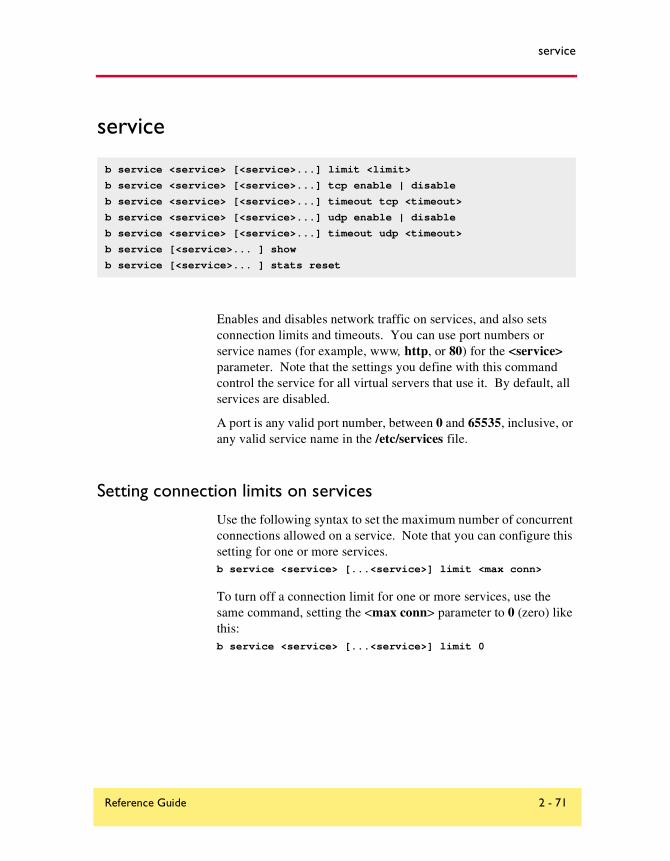
service
service
Enables and disables network traffic on services, and also sets connection limits and timeouts. You can use port numbers or service names (for example, www, http, or 80) for the <service> parameter. Note that the settings you define with this command control the service for all virtual servers that use it. By default, all services are disabled.
A port is any valid port number, between 0 and 65535, inclusive, or any valid service name in the /etc/services file.
Setting connection limits on services
Use the following syntax to set the maximum number of concurrent connections allowed on a service. Note that you can configure this setting for one or more services.b service <service> [...<service>] limit <max conn>
To turn off a connection limit for one or more services, use the same command, setting the <max conn> parameter to 0 (zero) like this:b service <service> [...<service>] limit 0
b service <service> [<service>...] limit <limit>
b service <service> [<service>...] tcp enable | disable
b service <service> [<service>...] timeout tcp <timeout>
b service <service> [<service>...] udp enable | disable
b service <service> [<service>...] timeout udp <timeout>
b service [<service>... ] show
b service [<service>... ] stats reset
Reference Guide 2 - 71

Chapter 2: bigpipe Command Reference
Displaying service settings
Use the following command to display the settings for all services:b service show
Use the following syntax to display the settings for a specific service or services:b service <service> [...<service>] show
The system displays the output shown in Figure 2.16.
Configuring TCP servicesYou can enable or disable TCP for specific services. The default setting for all services is disabled. Use the following syntax to enable TCP for one or more services:b service <service> [...<service>] tcp enable
To disable TCP, use this syntax:b service <service> [...<service>] tcp disable
To set the idle connection timeout for TCP traffic
To set the TCP timeout on one or more services, where the <seconds> parameter is the number of seconds before an idle connection is dropped, use the following syntax:b service <service> [<service>...] timeout tcp <seconds>
For example, the following command sets the TCP timeout to 300 seconds for port 53:b service 53 timeout tcp 300
SERVICE 80 http tcp enabled timeout 1005 udp disabled timeout 60 (cur, max, limit, tot, reaped) = (0, 0, 0, 0, 0)
(pckts,bits) in = (0, 0), out = (0, 0)
Figure 2.16 Service settings
2 - 72 BIG-IP® Controller 4.0

service
To turn off TCP timeout for a service, use the above command, setting the <seconds> parameter to zero:b service 53 timeout tcp 0
Configuring UDP services
You can enable or disable UDP for specific services. The default setting for all services is disabled. Use the following syntax to enable UDP for one or more services:b service <service> [...<service>] udp enable
To disable UDP, use this syntax:b service <service> [...<service>] udp disable
To set the idle connection timeout for UDP traffic
To set the UDP timeout on one or more services, where the <seconds> parameter is the number of seconds before an idle connection is dropped, use the following syntax:b service <service> [<service>...] timeout udp <seconds>
For example, the following command sets the UDP timeout to 300 seconds for port 53:b service 53 timeout udp 300
To turn off UDP timeout for a service, use the above command, setting the <seconds> parameter to zero:b service 53 timeout udp 0
Reference Guide 2 - 73

Chapter 2: bigpipe Command Reference
snat
Defines one or more addresses that nodes can use as a source IP address when initiating connections to hosts on the external network. Note that clients cannot use SNAT addresses to connect directly to nodes.
b snat map <orig_ip> [...<orig_ip>] to <snat_ip><snat_ip> [unit <unit ID>] [netmask <ip>]
b snat map default to <snat_ip> [unit <unit ID>] [netmask <ip>]
b snat <snat_ip> [...<snat_ip>] delete | show
b snat default delete | show
b snat default dump [verbose]
b snat [<snat_ip> [...<snat_ip>] ] dump [verbose]
b snat globals show
b snat default show
b snat [<snat_ip> [...<snat_ip>] ] show
b snat [<orig_ip> [...<orig_ip>] limit <max_conn>
b snat limit <max_conn>
b snat default limit <max conn>
b snat <orig_ip> [...<orig_ip>] mirror enable | disable
b snat default mirror enable | disable
b snat <orig_ip> [...<orig_ip>] timeout tcp | udp <seconds>
b snat default timeout tcp | udp <seconds>
b snat <orig_ip> [...<orig_ip>] stats reset
b snat default stats reset
b snat <orig_ip> [...<orig_ip>]> disable | enable
b snat <snat_ip> [...<snat_ip>] vlans <vlan_list> disable | enable
b snat <snat_ip> [...<snat_ip>] vlans show
b snat <snat_ip> [...<snat_ip>] arp [enable|disable]
2 - 74 BIG-IP® Controller 4.0

snat
Defining the default SNAT
Use the following syntax to define the default SNAT. If you use the netmask parameter and it is different from the external interface default netmask, the command sets the netmask and derives the broadcast address. You can use the unit <unit ID> parameter to specify a unit in an active-active redundant configuration.
b snat map default to <snat_ip> [vlan <vlan_name> disable | enable] [unit <unit ID>] [netmask <ip>]
Creating individual SNAT addressesUse the following command syntax to create a SNAT mapping:
b snat map <node_ip> [...<node_ip>] to \<snat_ip> [vlan <vlan_name> disable | enable] [unit <unit ID>] [netmask <ip>]
If the netmask is different from the external interface default netmask, the command sets the netmask and derives the broadcast address.
Creating a network SNAT address You can specify a SNAT for which the original address is a network:snat map 192.168.1.0 to 192.168.2.45
snat 192.168.1.0 netmask 255.255.255.0
This assigns all addresses in the Class C network 192.168.1 to SNAT 192.168.2.45. The assigning of a netmask to the original address is applicable when the original address is a network, which has zeros as its host portion.
Reference Guide 2 - 75

Chapter 2: bigpipe Command Reference
SNAT auto-mapping
A VLAN may be mapped automatically to a SNAT address. This means that by enabling snat automap on an internal VLAN, a SNAT is performed on any connection made from that VLAN. For more information about SNAT auto-mapping, refer to Enabling and disabling SNAT auto-mapping, on page 2-101.
Deleting SNAT Addresses
The following syntax deletes a specific SNAT:b snat <snat_ip> | default delete
Disabling VLANs for a SNAT
A SNAT is mapped by default to all VLANs on the internal and external networks of the BIG-IP Controller. Any VLANs to which the SNAT is not to be mapped must be explicitly disabled using the vlan <vlan_name> disable syntax.
Showing SNAT mappings
The following bigpipe commands show mappings:b snat [<snat_ip>] [...<snat_ip>] show
b snat default show
The following commands show the current SNAT connections:b snat [<snat_ip>] [...<snat_ip>] dump [ verbose ]
b snat default dump [ verbose ]
The optional verbose keyword provides more detailed output.
The following command prints the global SNAT settings:b snat globals show
2 - 76 BIG-IP® Controller 4.0

snat
Limiting connections
Use the following commands to set the maximum number of concurrent connections allowed for one or more SNAT addresses. Zero indicates no limit.b snat <snat_ip> limit <max conn>
The default SNAT address connection limit is set with the following command:b snat default limit <max conn>
Set the global concurrent connection limit with this command:b snat limit <max conn>
Enabling mirroring for redundant systems
The following example sets SNAT mirroring for all SNAT connections originating at 192.168.225.100:b snat 192.168.225.100 mirror enable
Setting idle connection timeouts
Use the following command to set the timeout for idle TCP connections:b snat timeout tcp <seconds>
Use the following command to set the timeout for idle UDP connections. Note that you must have a timeout set for UDP connections; zero is not allowed:b snat timeout udp <seconds>
Use the following command to set the timeout for idle TCP connections originating at this node address. Set <seconds> to 0 (zero) to disable TCP timeout for these nodes.
b snat <node_ip> [...<node_ip>] timeout tcp <seconds>
Use the following command to set the timeout for idle TCP connections originating at the default node address. Set <seconds> to 0 (zero) to disable TCP timeout for these nodes.
Reference Guide 2 - 77

Chapter 2: bigpipe Command Reference
b snat default timeout tcp <seconds>
Use the following syntax to set the timeout for idle UDP connections originating at this node address. Note that you must have a timeout set for UDP connections; zero is not allowed:
b snat <node_ip> [...<node_ip>] timeout udp <seconds>
Use the following syntax to set the timeout for idle UDP connections originating at the default SNAT address. Note that you must have a timeout set for UDP connections; zero is not allowed:b snat default timeout udp <seconds>
Disabling ARP requests
By default, the BIG-IP Controller responds to ARP requests for the SNAT address and sends a gratuitous ARP request for router table update. If you want to disable the SNAT address for ARP requests, you must specify arp disable.
Clearing statistics
You can reset statistics by node address. Use the following syntax to clear all statistics for one or more nodes:b snat <node_ip> [ ...<node_ip> ] stats reset
Use the following command to reset the statistics to zero for the default:b snat default stats reset
2 - 78 BIG-IP® Controller 4.0

summary
summary
Displays a summary of current usage statistics. The output display format for the summary command is shown in Figure 2.17. You can find detailed descriptions of each of statistic displayed by the summary command in the BIG-IP Administrator Guide, Monitoring and Administration.
b summary
Reference Guide 2 - 79

Chapter 2: bigpipe Command Reference
BIG-IP total uptime = 1 (day) 4 (hr) 40 (min) 8 (sec)BIG-IP total uptime (secs) = 103208BIG-IP total # connections = 0BIG-IP total # pkts = 0BIG-IP total # bits = 0BIG-IP total # pkts(inbound) = 0BIG-IP total # bits(inbound) = 0BIG-IP total # pkts(outbound) = 0BIG-IP total # bits(outbound) = 0BIG-IP error no nodes available = 0BIG-IP tcp port deny = 0BIG-IP udp port deny = 0BIG-IP virtual tcp port deny = 0BIG-IP virtual udp port deny = 0BIG-IP max connections deny = 0BIG-IP virtual duplicate syn ssl = 0BIG-IP virtual duplicate syn wrong dest = 0BIG-IP virtual duplicate syn node down = 0BIG-IP virtual maint mode deny = 0BIG-IP virtual addr max connections deny = 0BIG-IP virtual path max connections deny = 0BIG-IP virtual non syn = 0BIG-IP error not in out table = 0BIG-IP error not in in table = 0BIG-IP error virtual fragment no port = 0BIG-IP error virtual fragment no conn = 0BIG-IP error standby shared drop = 0BIG-IP dropped inbound = 0BIG-IP dropped outbound = 0BIG-IP reaped = 0BIG-IP ssl reaped = 0BIG-IP persist reaped = 0BIG-IP udp reaped = 0BIG-IP malloc errors = 0BIG-IP bad type = 0BIG-IP mem pool total 96636758 mem pool used 95552 mem percent used 0.10
Figure 2.17 The summary output display
2 - 80 BIG-IP® Controller 4.0

trunk
trunk
The trunk command aggregates links (individual physical interfaces) to form a trunk. This link aggregation increases the bandwidth of the individual NICs in an additive manner. Thus, four fast Ethernet links, if aggregated, create a single 400 Mb/s link. The other advantage of link aggregation is link failover. If one link in a trunk goes down, traffic is simply redistributed over the remaining links.
A trunk must have a controlling link and acquires all the attributes of that controlling link from Layer 2 and above. Thus, the trunk automatically acquires the VLAN membership of the controlling link but does not acquire its media type and speed. Outbound packets to the controlling link are load balanced across all of the known-good links in the trunk. Inbound packets from any link in the trunk are treated as if they came from the controlling link.
A maximum of eight links may be aggregated. For optimal performance, links should be aggregated in powers of two. Thus ideally you will aggregate two, four, or eight links.
Creating a trunk
To create a trunk, use the following syntax:b trunk <controlling_if> define <if_list>
Interfaces are specified using the s.p convention, where s is slot number and p is port number. An <if_list> is one or more such interfaces, with multiple interfaces separated by spaces or commas. A range may be specified as follows:2.1-2.7
b trunk <controlling_if> define <if_list>
b trunk <controlling_if> show
b trunk show
Reference Guide 2 - 81

Chapter 2: bigpipe Command Reference
For more information on interface naming, refer to Interface naming convention, on page 1-115.
2 - 82 BIG-IP® Controller 4.0
unit
unit
The unit number on a BIG-IP Controller designates which virtual servers use a particular controller in an active-active redundant configuration. You can use the bigpipe unit command to display the unit number assigned to a particular BIG-IP Controller. For example, to display the unit number of the unit you are on, type the following command:b unit show
To display the unit number of the other controller in a redundant system, type in the following command:b unit peer show
Note
If you use this command on a redundant system in active/standby mode, the active controller shows as unit 1 and 2, and the standby controller has no unit numbers.
Tip
The bigpipe unit peer show command is the best way to determine whether the respective state mirroring daemons are connected.
b unit [show]
b unit peer [show]
Reference Guide 2 - 83

Chapter 2: bigpipe Command Reference
verbose
Used to modify the verbose log level. This command is an alternative to using the bigpipe global verbose command.
Table 2.10 defines the command and shows the equivalencies.
b verbose virtual_server_udp_port_denial
b verbose virtual_server_tcp_port_denial
b verbose bigip_udp_ort_denial
b verbose bigip_tcp_port_denial
b verbose command b global verbose command
b verbose bigip_udp_port_denial
Turns UDP port denial logging on. This logs UDP port denials to the BIG-IP Controller address.
b global verbose_log_level=1
b verbose bigip_tcp_port_denial
Turns TCP port denial logging on. This logs TCP port denials to the BIG-IP Controller address.
b global verbose_log_level=2
b verbose virtual_server_udp_port_denial
Turns virtual UDP port denial logging on. This logs UDP port denials to the virtual server address.
b global verbose_log_level=4
Table 2.10 bigpipe verbose and global verbose command equivalencies
2 - 84 BIG-IP® Controller 4.0

verbose
b verbose virtual_server_tcp_port_denial
Turns virtual TCP port denial logging on. This logs TCP port denials to the virtual server address.
b global verbose_log_level=8
b verbose bigip_udp_port_denialb verbose bigip_tcp_port_denialb verbose bigip_udp_ort_denialb verbose bigip_tcp_port_denial
Turns UDP and TCP port denial on for both virtual server and BIG-IP Controller addresses.
b global verbose_log_level=15
b verbose command b global verbose command
Table 2.10 bigpipe verbose and global verbose command equivalencies
Reference Guide 2 - 85

Chapter 2: bigpipe Command Reference
verify
Parses the command line and checks syntax without executing the specified command. This distinguishes between valid and invalid commands
Use the verify command followed by a command that you want to validate:b verify virtual 10.10.10.100:80 use pool my_pool
The command checks the syntax and logic, reporting any errors that would be encountered if the command executed.
Use the verify command together with the load <filename> command to validate the specified configuration file. For example, to check the syntax of the configuration file /config/altbigpipe.conf, use the following command:b verify load /config/altbigip.conf
b [log] verify <command...]
verify load [<filename>|-]
2 - 86 BIG-IP® Controller 4.0

version
version
Displays the version of the BIG-IP Controller’s operating system and the features enabled.
For example, for a BIG-IP Controller HA, the bigpipe version command displays the output shown in Figure 2.18.
b version
Product Code:BIG-IP HA
Enabled Features:SSL Gateway Gateway Failsafe Static Load Balancing Snat Nat Pools Akamaizer Full Proxy Late Binding HTTP Rules Mirroring Failover Node HA Dynamic Load Balancing Destination Address Affinity Cookie Persistence SSL Persistence Simple Persistence EAV ECV SSL ECV ECV Transparent Health Check Filter
Figure 2.18 The version output display
Reference Guide 2 - 87

Chapter 2: bigpipe Command Reference
virtual
Creates, deletes, and displays information about virtual servers. This command also sets connection mirroring, connection limits, and timeouts on a virtual server.
Defining a virtual server
Virtual servers are port-specific, and if you are configuring a site that supports more than one service, you need to configure one virtual server for each service offered by the site. Use the
b virtual <virt_ip>[:<service>] [unit <ID>] [netmask <ip>] [broadcast <ip>] use pool <pool_name>
b virtual <virt_ip>:<service> [/<bitmask>][unit <ID>] use pool <pool_name>
b virtual <virt_ip>[:<service>] [unit <ID>] [netmask <ip>] [broadcast <ip>] use rule <rule_name>
b virtual <virt_ip>[:<service>] [unit <ID>] [netmask <ip>] forward
b virtual <virt_ip>:<service> translate port enable | disable | show
b virtual <virt_ip>:<service> svc_down_reset enable | disable | show
b virtual <virt_ip>:<service> translate addr enable | disable | show
b virtual <virt_ip>:<service> lasthop pool <pool_name> | none | show
b virtual <virt_ip>:<service> mirror conn enable | disable | show
b virtual [<virt_ip:service>] stats reset
b virtual <virt_ip>:<service> accelerate enable | disable | show
b virtual <virt_ip>:<service> use pool <pool_name> accelerate disable
b virtual <virt_ip>:<service> vlans <vlan_list> disable | enable
b virtual <virt_ip>:<service> vlans show
b virtual <virt_ip> arp enable|disable|show
b virtual <virt_ip> any_ip enable | disable
b virtual <virt_ip> any_ip timeout <seconds>
b virtual <virt_ip>[:<service>] [...<virt_ip>[:<service>]] show
b virtual <virt_ip>[:<service>] [ ... <virt_ip>[:<service>]] enable | disable
b virtual <virt_ip>[:<service>] [ ... <virt_ip>[:<service>]] delete
b virtual <virt_ip>[:<service>] [... <virt_ip>[:<service>]] limit <max_conn>
2 - 88 BIG-IP® Controller 4.0

virtual
following syntax to define the pools or rules to which a virtual server maps. The unit <ID> parameter specifies which unit handles the virtual server in an active-active redundant configuration. You can associate pools or rules with a virtual server. The following sections describe the syntax for associating a pool or a rule with a virtual server.
To configure a virtual server to use a load balancing pool
Use the following syntax to create a virtual server that references a load balancing pool. Note that you must create a pool before you can create a virtual server that references the pool. For information about creating a pool, see Creating a pool, on page 2-45.
b virtual <virt_ip>:<service> [unit <ID>] use pool <pool_name>
For example, if you want to create a virtual server that references the pool my_pool, the command might look like this:b virtual 11.12.1.53:80 use pool my_pool
To configure a virtual server to use a load balancing rule
Use the following syntax to create a virtual server that references a load balancing rule. Note that you must create a rule before you can create the virtual server that references the rule. For information about creating a rule, see Associating a rule with virtual server, on page 2-66.
b virtual <virt_ip>:<service> [unit <ID>] use rule <rule_name>
For example, if you want to create a virtual server that references the rule my_rule, the command might look like this:b virtual 11.12.1.53:80 use pool my_rule
Displaying information about virtual servers
Use the following syntax to display information about all virtual servers included in the configuration:b virtual show
Use the following syntax to display information about one or more virtual servers included in the configuration:
b virtual <virt_ip>:<service> [...<virt_ip>:<service>] show
Reference Guide 2 - 89
Chapter 2: bigpipe Command Reference
The command displays information such as the nodes associated with each virtual server, the nodes’ status, and the current, total, and maximum number of connections managed by the virtual server since the BIG-IP Controller was last rebooted.
To reset statistics for a virtual server
Use the following command to reset the statistics for an individual virtual server:b virtual [<virt_ip>:<service>] stats reset
Disabling VLANs for a virtual server
A virtual server is mapped by default to all VLANs on the internal and external networks of the BIG-IP Controller. Any VLANs to which the virtual server is not to be mapped must be explicitly disabled using the vlan <vlan_name> disable syntax:
b virtual <virt_ip>:<service> vlans <vlan_list> disable | enable
All virtual servers that share a virtual IP address must use the same VLANs. Changing the VLAN mapping for a virtual server changes the VLAN mapping for all virtual servers that have the same virtual address.
Disabling ARP requests
By default, the BIG-IP controller responds to ARP requests for the virtual server address and sends a gratuitous ARP request for router table update. If you want to disable the virtual address for ARP requests, you must specify arp disable.
Setting a user-defined netmask and broadcast for a network virtual server
The default netmask for a virtual address, and for each virtual server hosted by that virtual address, is determined by the self IP of the virtual server VLAN, if any, and if not by the network class of the IP address entered for the virtual server. The default broadcast
2 - 90 BIG-IP® Controller 4.0

virtual
is automatically determined by the BIG-IP Controller, and it is based on the virtual address and the current netmask. You can override the default netmask and broadcast for a network virtual address only.
All virtual servers hosted by the virtual address use the netmask and broadcast of the virtual address, whether they are default values or they are user-defined values.
To define a custom netmask and broadcast
If you want to use a custom netmask and broadcast, you define both when you define the network virtual server:
b virtual <virt_ip>[:<service>] [vlan <vlan_name> disable | enable] [netmask <ip>] [broadcast <ip>] use pool <pool_name>
Note
The BIG-IP Controller calculates the broadcast based on the IP address and the netmask. A user-defined broadcast address is not necessary.
Again, even when you define a custom netmask and broadcast in a specific network virtual server definition, the settings apply to all virtual servers that use the same virtual address. The following sample command shows a user-defined netmask and broadcast:
b virtual www.SiteOne.com:http netmask 255.255.0.0 broadcast 10.0.140.255 use pool my_pool
The /bitmask option shown in the following example applies network and broadcast address masks. In this example, a 24-bit bitmask sets the network mask and broadcast address for the virtual server: b virtual 206.168.225.0:80/24 use pool my_pool
You can generate the same broadcast address by applying the 255.255.255.0 netmask. The effect of the bitmask is the same as applying the 255.255.255.0 netmask. The broadcast address is derived as 206.168.225.255 from the network mask for this virtual server.
Reference Guide 2 - 91

Chapter 2: bigpipe Command Reference
Setting a connection limit
The default setting is to have no limit to the number of concurrent connections allowed on a virtual server. You can set a concurrent connection limit on one or more virtual servers using the following command:
b virtual <virt_ip>[:<service>] [...<virt_ip>[:<service>] ] limit <max conn>
The following example shows two virtual servers set to have a concurrent connection limit of 5000 each:
b virtual www.SiteOne.com:http www.SiteTwo.com:ssl limit 5000
To turn off the limit, set the <max conn> variable to zero:b virtual <virt_ip>[:<service>] [...<virt_ip>[:<service>] ] limit 0
Setting translation properties for virtual addresses and ports
Turning port translation off for a virtual server is useful if you want to use the virtual server to load balance connections to any service. Use the following syntax to enable or disable port translation for a virtual server.
b virtual <virt_ip>:<service> translate port enable | disable | show
You can also configure the translation properties for a virtual server address. This option is useful when the BIG-IP Controller is load balancing devices that have the same IP address. This is typical with the nPath routing configuration where duplicate IP addresses are configured on the loopback device of several servers. Use the following syntax to enable or disable address translation for a virtual server.
b virtual <virt_ip>:<service> translate addr enable | disable | show
Setting up last hop pools for virtual serversIn cases where you have more than one router sending connections to a BIG-IP Controller, connections are automatically sent back through the same router from which they were received when the auto_lasthop global variable is enabled, as it is by default. If the
2 - 92 BIG-IP® Controller 4.0

virtual
global auto_lasthop is disabled for any reason (for example, you may not want it for an SSL gateway), you can direct your replies to the last hop router using a last hop pool
To configure a last hop pool, you must first create a pool containing the router inside addresses. After you create the pool, use the following syntax to configure a last hop pool for a virtual server:
b virtual <virt_ip>:<service> lasthop pool <pool_name> | none | show
To remove a lasthop pool from a virtual server:b virtual <virt_ip>:<service> lasthop pool <pool_name> none
Mirroring virtual server state
Mirroring provides seamless recovery for current connections. When you use the mirroring feature, the standby controller maintains the same state information as the active controller. Then when a failover occurs, transactions such as FTP file transfers continue as though uninterrupted.
Note
Mirroring slows BIG-IP Controller performance and is primarily for long-lived services like FTP and Telnet. Mirroring is not useful for short-lived connections like HTTP.
Since mirroring is not intended to be used for all connections, it must be specifically enabled for each virtual server.
To control mirroring for a virtual server, use the bigpipe virtual mirror command to enable or disable mirroring of connections. The syntax of the command is:
b virtual <virt_ip>:<service> mirror conn enable | disable
Reference Guide 2 - 93

Chapter 2: bigpipe Command Reference
To display the current mirroring setting for a virtual server, use the following syntax:b virtual <virt_ip>:<service> mirror conn show
Note
If you set up mirroring on a virtual server that supports FTP connections, you need to mirror the control port virtual server, and the data port virtual server.
The following example shows the two commands used to enable mirroring for virtual server v1 on the FTP control and data ports:b virtual v1:21 mirror conn enable
b virtual v1:20 mirror conn enable
Enabling and disabling a virtual server
You can remove an existing virtual server from network service, or return the virtual server to service, using the disable and enable keywords. When you disable a virtual server, the virtual server no longer accepts new connection requests, but it allows current connections to finish processing before the virtual server goes down. Use the following syntax to remove a virtual server from network service:
b virtual <virt_ip>:<service> [...<virt_ip>:<service>] disable
Use the following syntax to return a virtual server to network service:b virtual <virt_ip>:<service> enable
Enabling and disabling a virtual address
You can remove an existing virtual address from network service, or return the virtual address to service, using the disable and enable keywords. Note that when you enable or disable a virtual address, you inherently enable or disable all of the virtual servers that use the virtual address.b virtual <virt_ip> disable
2 - 94 BIG-IP® Controller 4.0

virtual
Use the following syntax to return a virtual address to network service:b virtual <virt_ip> enable
Displaying information about virtual addresses
You can also display information about the virtual addresses that host individual virtual servers. Use the following syntax to display information about one or more virtual addresses included in the configuration:b virtual <virt_ip> [... <virt_ip> ] show
The command displays information such as the virtual servers associated with each virtual address, the status, and the current, total, and maximum number of connections managed by the virtual address since the BIG-IP Controller was last rebooted, or since the BIG-IP Controller became the active unit (redundant configurations only).
Deleting a virtual server
Use the following syntax to permanently delete one or more virtual servers from the BIG-IP Controller configuration:
b virtual <virt_ip>:<service> [... <virt_ip>:<service>] delete
Turning software acceleration off for virtual servers using IPFW rate filters
Additional enhancements are included in this release that speed packet flow for TCP connections when the packets are not fragmented. In most configurations these software enhancements are automatically turned on and do not require any additional configuration.
However, you may want to turn off these enhancements for individual virtual servers that use IPFW rate filters. With the speed enhancements on, IPFW only examines the first SYN packet in any
Reference Guide 2 - 95
Chapter 2: bigpipe Command Reference
given connection. If you want to filter all packets, you should turn off the speed enhancements. To do this, you must first set the global state of the system on, and then you must turn off the feature for individual virtual servers that use IPFW rate filtering. You can change the settings for these enhancements from the command line or in the Configuration utility.
To set software acceleration controls
Before you can turn off software acceleration for a virtual server, you must set the global variable fastflow_active to on with the following command:b global fastflow_active on
After you set the sysctl variable, use the following bigpipe commands to disable software acceleration for existing virtual servers that use IPFW rate filtering:b virtual <ip>:<service> accelerate disable
For example, if you want to turn acceleration off for the virtual server 10.10.10.50:80, type the following command:b virtual 10.10.10.50:80 accelerate disable
You can define a virtual server with acceleration disabled using the following syntax:
b virtual <ip>:<service> use pool the_pool accelerate disable
For example, if you want to define the virtual server 10.10.10.50:80 with the pool IPFW_pool and acceleration turned off, type the following command:
b virtual 10.10.10.50:80 use pool IPFW_pool accelerate disable
Enabling and disabling Any IP
The any_ip flag, if enabled, enables the virtual server for services other than TCP and UDP. It is used to permit IPSEC (IP Security Protocol) for VPN connections.
2 - 96 BIG-IP® Controller 4.0
vlan
vlan
The vlan command defines VLANs, VLAN mappings, and VLAN properties. By default, each interface on a BIG-IP is an untagged member of an interface-group VLAN. The lowest-numbered interface is assigned to the external VLAN, the interface on the main board is assigned to the admin VLAN, and all other interfaces are assigned to the internal VLAN.
Using the vlan command, you can create tagged and untagged VLANs, make and change assignments of VLANs to interfaces, and configure a range of VLAN attributes. This includes
b vlan <vlan_name>
b vlan <name> rename <new_name>
b vlan <vlan_name> delete
b vlan <vlan_name> tag <tag_number>
b vlan <vlan_name> interfaces add [tagged] <if_list>
b vlan <vlan_name> interfaces delete <if_list>
b vlan <vlan_name> interfaces delete all
b vlan <vlan_name> interfaces show
b vlan <vlan_name> port_lockdown enable | disable
b vlan <vlan_name> bridging enable|disable
b vlan <vlangroup_name> proxy_forward enable | disable
b vlan <vlan_name> failsafe arm|disarm|show
b vlan <vlan_name> timeout <seconds>|show
b vlan <vlan_name> snat automap
b vlan show
b vlan <vlan_name> show
b vlan <vlan_name> interfaces show
b vlan <vlan_name> rename <new_vlan_name>
b vlan <if_name> mac_masq <mac_addr> | show
b vlan <if_name> mac_masq 0:0:0:0:0
Reference Guide 2 - 97

Chapter 2: bigpipe Command Reference
enabling/disabling of port lockdown, arming and disarming failsafe, and setting the failure timeout. VLAN configuration options are shown in Table 2.11
VLAN flexibility is such that separate IP networks can belong to a single VLAN, while a single IP network can be split among multiple VLANs. (The latter case allows the BIG-IP Controller to be inserted into an existing LAN without renaming the nodes.) In either case, the separate networks can be made to behave like a single network for intercommunication purposes. This is done in one of two ways:
◆ For nodes on different networks within the same VLAN, direct packet exchange is performed using feature called VLAN bridging.
Attributes Description
Default VLAN configuration
The First-Time Boot utility provides a default VLAN configuration. On a typical controller with two interfaces, you create an internal and external VLAN.
VLAN Create, rename, or delete a VLAN. Typically, one VLAN is assigned to one interface.
Tag VLANs You can tag VLANs and add multiple tagged VLANs to a single interface.
VLAN security
You can set port lockdown by VLAN.
Set fail-safe timeouts
You can set a failsafe timeout on a VLAN. You can use a failsafe timeout to trigger fail-over in a redundant system.
Self IP addresses
You can set self IP addresses for VLANs.
MAC masquerade
You can use this attribute to set up a media access control (MAC) address that is shared by redundant controllers. This allows you to use the BIG-IP Controllers in a topology with secure hubs.
Table 2.11 VLAN configuration options
2 - 98 BIG-IP® Controller 4.0
vlan
◆ For nodes on the same IP network on different VLANs, direct packet exchange is performed by a feature called L2 forwarding. This requires that the VLANs be grouped.
Except for self-addresses (which must be mapped explicitly to VLANs), all addresses created as objects on the BIG-IP controller (virtual servers, NATs, SNATs, and proxies) are automatically mapped to all untagged VLANs. Thus bridging will always take place.
Creating and assigning a VLAN
To create a VLAN, use the following syntax:b vlan <name>
<name> is typically symbolic, as in:b vlan vlan5
Typically you will define a VLAN and specify the interfaces on the VLAN in the same command:b vlan vlan5 interfaces add [tagged] <if_list>
Tagged VLANsA new tagged VLAN is created using the bigpipe vlan tag command, specifying a tag number. For example: b vlan my_vlan tag 1209
A tagged VLAN is mapped to an interface or interfaces (or an untagged VLAN is tagged and mapped an interface or interfaces) using the tagged flag. For example: b vlan external interfaces add tagged 4.1 5.1 5.2
The effect of the command is to place a tag on interfaces 4.1.and 5.1, which in turn makes external a tagged VLAN. (However, it remains an untagged VLAN for interfaces which are part of it but not tagged.)
Reference Guide 2 - 99
Chapter 2: bigpipe Command Reference
An interface can have more than one tag; it can be a member of more than one tagged VLAN. b vlan external interfaces add tagged 4.1
b vlan internal interfaces add tagged 4.1
b vlan admin interfaces add tagged 4.1
This permits tagged VLANS to form a VLAN trunk on a single interface.
Enabling and disabling port lockdown
You can lock down a VLAN to prevent direct connection to the BIG-IP Controller through that VLAN.
Setting the fail-over timeout and arming the fail-safe
For redundant BIG-IP Controller pairs, failover (activation of the inactive system) occurs when loss of traffic is detected on a VLAN and traffic is not restored during the failover timeout period for that VLAN. A failsafe mechanism may be enable to attempt to generate traffic when half the timeout has elapsed. If the attempt is successful, the failover is aborted.
Using the vlan command, you may set the timeout period and also arm or disarm the fail-safe.
To set the timeout, type:b vlan <vlan_name> timeout <timeout_in_seconds>
To arm the failsafe, type:b vlan <vlan_name> failsafe arm
To disarm the failsafe, type:b vlan <vlan_name> failsafe disarm
2 - 100 BIG-IP® Controller 4.0

vlan
Enabling and disabling SNAT auto-mapping
A VLAN may be mapped automatically to a SNAT address. This means that by enabling snat automap on an internal VLAN, a SNAT is performed on any connection made from that VLAN. If the external VLAN has one self IP address enabled for snat automap, the translation address will be that self IP address.
For VLANs external and internal, this would be implemented as follows:b vlan internal snat automap enable
b self 10.0.0.1 vlan external snat automap enable
If the external VLAN has more than one self IP address enabled for snat automap (implying more than one IP network), the following rules are followed:
◆ If the connection is handled by a non-forwarding virtual server, the translation address will be the self IP address for the node selected by load balancing.
◆ If the connection is handled by a forwarding virtual server or no virtual server, the translation address will be the IP address of the next hop to the destination.
◆ If there are no self addresses that match the IP network of the node or the next hop, any self IP on the VLAN is eligible.
The SNAT auto-map feature is useful in the following cases:
◆ Where a traditional single SNAT address would quickly exhaust the number of ephemeral ports available. As long as there is more than one eligible self IP address, SNAT auto-mapping can increase the number of simultaneous connections possible by using the same ephemeral port on multiple addresses.
◆ When the equivalent of a default SNAT is required for BIG-IP Controllers in active-active mode. (The conventional default SNAT does not work in active-active mode.)
◆ Where there is a need to ensure that outbound traffic returning through ISPs or NAT-less firewalls returns through the same ISP or firewall.
Reference Guide 2 - 101

Chapter 2: bigpipe Command Reference
ISPs and NAT-less firewalls are handled in the following manner. If multiple external interfaces are available, the inside addresses of the firewalls in the load balancing pool may each be connected to different interfaces and assigned to different VLANs. Each VLAN is then automatically mapped to a SNAT when the snat automap flag is enabled. The snat automap flag must also be enabled for the internal VLAN. For example, if the internal VLAN were named internal, and the external VLANs were named external1 and external2, the following commands would be entered:b vlan internal snat_automap enable
b vlan external1 snat_automap enable
b vlan external2 snat_automap enable
If multiple external interfaces are not available, the ISP routers or firewalls are assigned to different IP networks. This will already be the case for ISPs. For firewalls, the separate IP address ranges must be established on the inside and outside interfaces of each firewall. The separate networks are then assigned separate self addresses, for example, 10.0.0.1 and 11.0.0.1. Thus if the internal and external VLANs were named internal and external, the following commands would be entered:b self 10.0.0.1 vlans add external snat automap enable
b self 11.0.0.1 vlans add external snat automap enable
b vlan internal snat automap enable
Setting the MAC masquerade address
Sharing the MAC masquerade address makes it possible to use BIG-IP Controllers in a network topology using secure hubs. The MAC address for a VLAN is the first interface to which the VLAN is mapped. You can view the VLAN-to--interface mapping using the following command:b vlan show
You can view the media access control (MAC) address on a given controller using the following command:b interface show
Use the following syntax to set the MAC masquerade address that will be shared by both BIG-IP Controllers in the redundant system.
2 - 102 BIG-IP® Controller 4.0

vlan
b interface <ifname> mac_masq <MAC_addr>
WARNING
You must specify a default route before using the mac_masq command. You specify the default route in the /etc/hosts and /etc/netstart files.
Find the MAC address on both the active and standby units and choose one that is similar but unique. A safe technique for choosing the shared MAC address follows:
Suppose you want to set up mac_masq on the external interfaces. Using the b interface show command on the active and standby units, you note that their MAC addresses are:Active: 3.1 = 0:0:0:ac:4c:a2
Standby: 3.1 = 0:0:0:ad:4d:f3
In order to avoid packet collisions, you now must choose a unique MAC address. The safest way to do this is to select one of the addresses and logically OR the first byte with 0x40. This makes the MAC address a locally administered MAC address.
In this example, either 40:0:0:ac:4c:a2 or 40:0:0:ad:4d:f3 would be a suitable shared MAC address to use on both BIG-IP Controllers in the redundant system.
The shared MAC address is used only when the BIG-IP Controller is in active mode. When the unit is in standby mode, the original MAC address of the network card is used.
If you do not configure mac_masq on startup, or when transitioning from standby mode to active mode, the BIG-IP Controller sends gratuitous ARP requests to notify the default router and other machines on the local Ethernet segment that its MAC address has changed. See RFC 826 for more details on ARP.
Note
You can use the same technique to configure a shared MAC address for each interface.
Reference Guide 2 - 103

Chapter 2: bigpipe Command Reference
vlangroup
The vlangroup command defines a VLAN group, which is a grouping of two or more VLANs belonging to the same IP network for the purpose of allowing L2 packet forwarding between those VLANs.
The VLANs between which the packets are to be passed must be on the same IP network, and they must be grouped using the vlangroup command. For example:b vlangroup network11 { vlans add internal external }
A self IP address must be assigned to the VLAN group using the following command:b self <ip_addr> vlan network11
L2 forwarding must be enabled for the VLAN group using the vlan proxy_forward attribute. This attribute is enabled by default when the VLAN group is enabled.
b vlangroup <vlagroup_name> { vlans add <vlan_list> }
b vlangroup <vlangroup_name> delete
2 - 104 BIG-IP® Controller 4.0

3
BIG-IP Controller Base Configuration Tools

Introducing the BIG-IP Controller base configuration tools
Introducing the BIG-IP Controller base configuration tools
The BIG-IP Controller includes a set of special tools for configuring the controller itself, or its redundant partner, as opposed to the larger network. One of these tools, config, you will normally run when the controller is first installed as part of the installation procedure. You may also use config, as well as the other special configuration utilities, to change existing settings at any time.
The following configuration utilities are available on the BIG-IP Controller:
◆ configThis utility is also known as the First-Time Boot utility. This utility runs all the other utilities required to configure or reconfigure the BIG-IP Controller, including most of the utilities in this list.
◆ config comboUse this utility to select the feature set you want to use on the combined product platform. You can choose from the following feature sets: BIG-IP Controller LoadBalancer, BIG-IP Cache Controller, or BIG-IP FireGuard Controller.
◆ config dnsUse this utility to configure or reconfigure an optional DNS proxy.
◆ config ftpdUse this utility to configure or reconfigure FTP.
◆ config httpdUse this utility to reconfigure the web server on the BIG-IP Controller.
◆ config passwordUse this utility to change your password.
◆ config redundantUse this utility to configure or reconfigure redundant system settings.
Reference Guide 3 - 1
Chapter 3: BIG-IP Controller Base Configuration Tools
◆ config remoteUse this utility to prepare a new redundant system for remote access. This utility also prepares the controller for the commands that synchronize redundant controllers.
◆ config rshdUse this utility to configure or reconfigure RSH.
◆ config sshdUse this utility to configure or reconfigure SSH.
◆ config telnetdUse this utility to configure or reconfigure Telnet and FTP.
◆ config timezoneUse this utility to set or change your time zone.
3 - 2 BIG-IP® Controller 4.0
config
configThis utility starts automatically the first time you boot up a BIG-IP Controller. The config utility, referred to as the First-Time Boot utility, is a wizard that walks you through a brief series of required configuration tasks. These tasks include defining a root password and configuring IP addresses for the interfaces. You can also run the First-Time Boot utility to reconfigure a controller.
The First-Time Boot utility is organized into three phases: configure, confirm, and commit.
When using the config utility, you first configure all of the required information, then you have the opportunity to confirm each individual setting or correct it if necessary, and finally your confirmed settings are committed and saved to the system. Note that the screens you see are tailored to the specific hardware and software configuration that you have.
If you have a stand-alone system, for example, the First-Time Boot utility skips the redundant system screens.
To run the First-Time Boot utility, type in the following command:config
Selecting a keyboard
Select the type of keyboard you want use with the BIG-IP Controller. The following options are available:
• Belgian
• Bulgarian MIK
• French
• German
• Japanese - 106 key
• Norwegian
• Spanish
• Swedish
• US + Cyrillic
Reference Guide 3 - 3

Chapter 3: BIG-IP Controller Base Configuration Tools
• US - Standard 101 key
• United Kingdom
Product selectionIf you are configuring a BIG-IP Cache Controller, FireGuard, or Load Balancer, you must now select one of these three as your product. When you have made your selection, the features supported by that product will be enabled.
Note
You may change your product selection at a later time using the config combo command.
WARNING
Once you have configured your system based on one of the three product selections (BIG-IP Cache Controller, FireGuard, or Load Balancer), changing the product selection will most likely invalidate that configuration. Therefore you will need to change and update your configuration after you have rebooted the system under the new product selection.
Defining a root password
A root password allows you command line administrative access to the BIG-IP Controller system. The password must contain a minimum of 6 characters, but no more than 32 characters. Passwords are case-sensitive, and we recommend that your password contain a combination of upper- and lower-case characters, as well as numbers and punctuation characters. Once you enter a password, the First-Time Boot utility prompts you to confirm your root password by typing it again. If the two
3 - 4 BIG-IP® Controller 4.0

config
passwords match, your password is immediately saved. If the two passwords do not match, the First-Time Boot utility provides an error message and prompts you to re-enter your password.
WARNING
The root password and keyboard selection are the only settings that are saved immediately, rather than confirmed and committed at the end of the First-Time Boot utility process. You cannot change the root password until the First-Time Boot utility completes and you reboot the BIG-IP Controller (see the BIG-IP Administration Guide, Monitoring and Administration). Note that you can change other system settings when the First-Time Boot utility prompts you to confirm your configuration settings.
Defining a host name
The host name identifies the BIG-IP Controller itself. Host names must be fully qualified domain names (FQDNs). The host portion of the name must start with a letter, and must be at least two characters.
Configuring a default route
If a BIG-IP Controller does not have a predefined route for network traffic, the controller automatically sends traffic to the IP address that you define as the default route. Typically, a default route is set to a router’s IP address.
Setting up a redundant system
On the Configure BIG-IP Interfaces screen, select Yes if you have a redundant system.
Reference Guide 3 - 5
Chapter 3: BIG-IP Controller Base Configuration Tools
Selecting a unit ID
If you are configuring a redundant system, the First-Time Boot utility prompts you to provide a unit ID and the IP address for fail-over for the BIG-IP Controller. The default unit ID number is 1. If this is the first controller in the redundant system, use the default. When you configure the second controller in the system, type 2. These unit IDs are used for active-active redundant controller configuration.
Choosing a fail-over IP address
If you are configuring a redundant system, after you type in a unit number, the First-Time Boot utility prompts you to provide an IP address for fail-over. Type in the IP address configured on the internal interface of the other BIG-IP Controller.
Configuring interfaces
Configure media settings for each interface. The media type options depend on the network interface card included in your hardware configuration. The First-Time Boot utility prompts you with the settings that apply to the interface installed in the controller. The BIG-IP Controller supports the following types:
• auto
• 10baseT
• 10baseT,FDX
• 100baseTX
• 100baseTX,FDX
• Gigabit Ethernet
Note
If you do not know the correct setting for your switch or hub, you can set the media type to auto and change it later when you know the correct setting. Check your switch or hub documentation for this information.
3 - 6 BIG-IP® Controller 4.0

config
WARNING
The configuration utility lists only the network interface devices that it detects during boot up. If the utility lists only one interface device, the network adapter may have come loose during shipping. Check the LED indicators on the network adapters to ensure that they are working and are connected.
Defining VLANs and IP addresses
You can create a new VLAN or use the default internal and external VLANs to create the BIG-IP Controller configuration.
Determine whether you want to have security turned on or off for a VLAN. Then, type the IP address settings for the VLAN. The IP address settings include:
• Security settings
• IP address, netmask, and broadcast
• Floating self IP address, netmask, and broadcast
We recommend that you set the floating self IP address as the default route for target devices, such as servers. The floating self IP address is owned by the active controller in an active/standby configuration.
Note
The IP address of the external VLAN is not the IP address of your site or sites. The IP addresses of the sites themselves are specified by the virtual IP addresses associated with each virtual server you configure.
Assigning interfaces to VLANs
After you configure the VLANs you want to use on the controller, you can assign interfaces to the VLANs. If you use the default internal and external VLANs, we recommend that you assign at least one interface to the external VLAN, and at least one interface
Reference Guide 3 - 7

Chapter 3: BIG-IP Controller Base Configuration Tools
to the internal VLAN. The external VLAN is the one on which the BIG-IP Controller receives connection requests. The internal VLAN is typically the one that is connected to the network of servers, firewalls, or other equipment that the BIG-IP Controller load balances.
Selecting the primary IP address
After you assign interfaces to VLANs, you can choose one VLAN/IP address combination as the primary IP address to associate with the controller host name.
Configuring settings for remote web access
The BIG-IP web server provides the ability to set up remote web access on each VLAN. When you set up web access on a VLAN, you can connect to the web-based configuration utility through the VLAN. To enable web access, specify a fully qualified domain name (FQDN) for each VLAN. The BIG-IP web server configuration also requires that you define a user ID and password. If SSL is available, the configuration also generates authentication certificates.
The First-Time Boot utility guides you through a series of screens to set up remote web access.
• The first screen prompts you to select the VLAN you want to configure for web access. After you select an interface to configure, the utility prompts you to type a fully qualified domain name (FQDN) for the interface. You can configure web access on one or more interfaces.
• After you configure the interface, the utility prompts you for a user name and password. After you type a user name and password, the utility prompts you for a vendor support account. The vendor support account is not required.
3 - 8 BIG-IP® Controller 4.0

config
• The certification screen prompts you for country, state, city, company, and division.
WARNING
If you ever change the IP addresses or host names on the BIG-IP Controller interfaces, you must reconfigure the BIG-IP web server to reflect your new settings. You can run the re-configuration utility from the command line using the following command:
reconfig-httpd
You can also add users to the existing password file, change a password for an existing user, or recreate the password file, without actually repeating the remote web server configuration process.
WARNING
If you have modified the remote web server configuration outside of the configuration utility, be aware that some changes may be lost when you run the reconfig httpd utility. This utility overwrites the httpd.conf file and openssl.conf, but does not warn you before doing so.
Configuring a time zone
Next, you need to specify your time zone. This ensures that the clock for the BIG-IP Controller is set correctly, and that dates and times recorded in log files correspond to the time zone of the system administrator. Scroll through the list to find the time zone at your location. Note that one option may appear with multiple names. Select the time zone you want to use, and press the Enter key to continue.
Reference Guide 3 - 9

Chapter 3: BIG-IP Controller Base Configuration Tools
Configuring the DNS forwarding proxy settings
You only need to complete this step if you want machines inside your BIG-IP Controller managed network to use DNS servers outside of that network (for example, for reverse DNS lookup from a web server).
Specify the DNS name server and domain name for DNS proxy forwarding by the BIG-IP Controller. For more information on DNS proxy forwarding see the BIG-IP Installation Guide.
Configuring remote command line access
After you configure remote web access, the First-Time Boot utility prompts you to configure remote command line access. On most BIG-IP Controllers, the first screen you see is the Configure SSH screen, which prompts you to type an IP address for SSH command line access. If SSH is not available, you are prompted to configure access through Telnet and FTP instead.
When you configure shell access, the First-Time Boot utility prompts you to create a support account for that method. You can use this support account to provide a support engineer access to the BIG-IP Controller.
When the First-Time Boot utility prompts you to enter an IP address for administration, you can type a single IP address or a range of IP addresses, from which the BIG-IP Controller will accept administrative connections (either remote shell connections, or connections to the BIG-IP web server). To specify a range of IP addresses, you can use the asterisk (*) as a wildcard character in the IP addresses.
The following example allows remote administration from all hosts on the 192.168.2 network:
3 - 10 BIG-IP® Controller 4.0

config
192.168.2.*
Note
For administration purposes, you can connect to the BIG-IP Controller floating self IP address, which always connects you to an active controller in an active/standby redundant system. To connect to a specific controller, simply connect directly to the IP address of that BIG-IP Controller.
NTP support
You can synchronize the time on the controller to a public time server by using Network Time Protocol (NTP). NTP is built on top of TCP/IP and assures accurate, local timekeeping with reference to clocks located on the Internet. This protocol is capable of synchronizing distributed clocks, within milliseconds, over long periods of time. If you choose to enable NTP, make sure UDP port 123 is open in both directions when the controller is behind a firewall.
NameSurfer
If you have the 3-DNS module installed, you can configure NameSurfer to handle DNS zone file management for the controller. We strongly recommend that you configure NameSurfer to handle zone file management by selecting NameSurfer to be the master on the controller. If you select NameSurfer as the master, NameSurfer converts the DNS zone files on the controller and handles all changes and updates to these files. (You can access the NameSurfer application directly from the Configuration utility for the 3-DNS module).
Reference Guide 3 - 11

Chapter 3: BIG-IP Controller Base Configuration Tools
config comboThe config combo utility repeats the segment of config in which you select BIG-IP Cache Controller, BIG-IP FireGuard, or BIG-IP Load Balancer as your product. The config combo command is used primarily to change an existing product selection.
WARNING
Once you have configured your system based on one of the three product selections (BIG-IP Cache Controller, BIG-IP FireGuard, or BIG-IP Load Balancer), changing the product selection will most likely invalidate that configuration. Therefore you will need to change and update your configuration after you have rebooted the system under the new product selection.
3 - 12 BIG-IP® Controller 4.0

config dns
config dnsRuns only the Configure DNS Proxy segment of config, assuming you want machines inside your BIG-IP Controller managed network to use DNS servers outside of that network (for example, for reverse DNS lookup from a web server).
Specify the DNS name server and domain name for DNS proxy forwarding by the BIG-IP Controller. For more information on DNS proxy forwarding see the BIG-IP Installation Guide.
Reference Guide 3 - 13

Chapter 3: BIG-IP Controller Base Configuration Tools
config ftpdUse this utility to configure FTP on the BIG-IP Controller. This utility prompts you for an IP address from which administrators may access the BIG-IP Controller with FTP. You can use wildcard characters (*) to include all addresses from a specific part of the network. This utility also prompts you to create a support account for access by technical support.
If the service port for FTP is closed, this script opens the service port to permit FTP connections to the BIG-IP Controller.
To run the secure shell configuration utility, type in the following command:config ftpd
Note
Re-running config sshd again replaces the current configuration.
3 - 14 BIG-IP® Controller 4.0

config httpd
config httpdUse the reconfig httpd configuration utility to reconfigure the HTTPD server on a BIG-IP Controller.
This script enables you to assign an FQNN to your internal and external VLANs. This utility also prompts you to create a support account for access by technical support.
If the service port for the web server on the BIG-IP controller (httpd) is closed, this script automatically opens the service port to permit access to the web server.
Reference Guide 3 - 15

Chapter 3: BIG-IP Controller Base Configuration Tools
config passwordRuns only the config segment for configuring the password.
3 - 16 BIG-IP® Controller 4.0

config redundant
config redundantconfig redundant is identical to config except that it skips the initial steps for setting keyboard type and root password. config redundant is for re-configuration of a standalone unit as one of a redundant pair, or for the addition of a second unit to complete a redundant pair.
Reference Guide 3 - 17

Chapter 3: BIG-IP Controller Base Configuration Tools
config remoteRuns only the config segment for configuring each controller in a redundant system in order to share keys with the peer BIG-IP Controller.
The script prompts you for the root password of the other controller in the redundant system. After confirming your input, the config remote script attempts to access the peer system and configure both systems to communicate with one another. This provides the secure communication channel that the controllers use to exchange configuration data when you run the bigpipe configsync option, or use the Config Sync button in the Configuration utility.
To run the config remote script, type the following command on the command line:config remote
3 - 18 BIG-IP® Controller 4.0
config rshd
config rshdUse the config rshd configuration utility to configure the remote shell (rshd) server on a BIG-IP Controller. This utility prompts you for an IP address from which administrators may access the BIG-IP Controller. You can use wildcard characters (*) to include all addresses from a specific part of the network. This utility also prompts you to create a support account for access by technical support.
If inetd is not currently configured, this script configures inetd for the remote shell server (rshd). If the service port for rsh is closed, this utility opens the service port to permit rsh connections to the BIG-IP Controller.
To run the rsh configuration utility, type in the following command:config rshd
Note
Running config rshd again replaces the current configuration.
Reference Guide 3 - 19

Chapter 3: BIG-IP Controller Base Configuration Tools
config sshdRuns only the config segment for configuring secure shell server (sshd) on a BIG-IP Controller. This utility prompts you for an IP address from which administrators may access the BIG-IP Controller with SSH. You can use wildcard characters (*) to include all addresses from a specific part of the network. This utility also prompts you to create a support account for access by technical support.
If the service port for SSH is closed, this script opens the service port to permit SSH connections to the BIG-IP Controller.
To run the secure shell configuration utility, type in the following command:config sshd
Note
Re-running config sshd again replaces the current configuration.
3 - 20 BIG-IP® Controller 4.0

config telnetd
config telnetdRuns only the config segment for configuring the Telnet and FTP servers on a BIG-IP Controller. The script prompts you to configure each service independently. This allows you to enable Telnet but not FTP, for example.
The script prompts you for a configuration address for each service from which administrators may access the BIG-IP Controller. You can use wildcard characters (*) to include all addresses from a specific part of the network. This utility also prompts you to create a support account for access by technical support.
If inetd is not currently configured, this script configures inetd for the requested services. If the ports for Telnet or FTP are closed, this script opens the ports to permit Telnet or FTP connections to the BIG-IP Controller.
To run the Telnet/FTP configuration utility, type in the following command:config telnetd
Note
Running config telnetd again replaces the current configuration.
Reference Guide 3 - 21

Chapter 3: BIG-IP Controller Base Configuration Tools
config timezoneRuns only the config segment for configuring the time zone. The time zone setting ensures that the clock for the BIG-IP Controller is set correctly, and that dates and times recorded in log files correspond to the time zone of the system administrator. Scroll through the list to find the time zone at your location. Note that one option may appear with multiple names. Select the time zone you want to use, and press the Enter key to continue.
3 - 22 BIG-IP® Controller 4.0

4
BIG/db Configuration Keys

Supported BIG/db configuration keys
Supported BIG/db configuration keysThe BIG/db is a database that contains configuration elements for the BIG-IP Controller. Configuration options that are supported by BIG/db include:
• Fail-over
• State mirroring
• Gateway failsafe pingers
• Configuration synchronization
• Interface related settings
• Health monitor settings
The BIG/db keys for each of these features are described in the following series of tables. The keys are viewed and set using the bigpipe db command.b db get <key>
b db get <reg_exp>
b db set <key>
b db set <key> = <value>
b db unset <key>
b db unset <reg_exp>
b db dump [filename]
Displaying current setting of a BIG/db configuration key
To display the value of a BIG/db configuration key, use the following syntax:b db get <key>
b db get <regular_exp>
For example, the following command displays the value of Local.Bigip.FTB.HostNumber:b db get Local.Bigip.FTB.HostNumber
The following command displays the value of all local keys:b db get Local.*
Reference Guide 4 - 1

Chapter 4: BIG/db Configuration Keys
Setting a BIG/db configuration key
To create (set) a BIG/db configuration key, use the following syntax:b db set <key>
To set a BIG/db configuration key and assign a value to it, use the following syntaxb db set <key> = <value>
For example, the following command sets Local.Bigip.FTB.HostNumber mode to on:b db set Local.Bigip.FTB.HostNumber = 1
Unsetting a BIG/db configuration key
To unset a BIG/db configuration key, use the following syntax.b db unset <key>
b db unset <regular_exp>
For example, the following command unsets Local.Bigip.FTB.HostNumber:b db unset Local.Bigip.FTB.HostNumber
The following command unsets all local keys:b db unset set Local.*
Failover and Cluster keysThe failover and cluster keys (Table 4.1) control failover from the active to the standby unit in a BIG-IP Controller redundant system. If you change one of these values, you must update the BIG-IP Controller configuration with the bigpipe failover init command (which is the same as bigstart reinit sod). This command forces the system to reread the BIG/db database and use the new values. To run this command, type the following:b failover init
4 - 2 BIG-IP® Controller 4.0

Supported BIG/db configuration keys
Fail-Over Key Name Description
Common.Bigip.Failover.AwaitPeerAliveDelay = 2 Delay in seconds before testing whether peer is active. The default value is 2.
Common.Bigip.Failover.AwaitPeerDeadDelay = 1 Delay in seconds before testing whether the peer has failed. The default value is 1.
Common.Bigip.Failover.FailbackDelay= 60 Use active-active mode if set to one. By default this is off and active-standby mode is used.
Local.Bigip.Failover.UnitId This key is required. Each controller must have a unique unit ID of 1 or 2 in the event that network communication is not possible with its peer.
Common.Bigip.Failover.ActiveMode = 0 Use active-active mode if set to 1. By default, this is off and active/standby mode is used.
Common.Bigip.Failover.ManFailBack = 0 If using active-active mode, the fail-over mechanism waits until receiving a command before surrendering resources to a rebooted machine.
Common.Bigip.Failover.NoSyncTime By default, one BIG-IP Controller synchronizes its time with the other. Set this key to 1 to turn off the time synchronization feature.
Common.Bigip.Failover.DbgFile File into which sod logs the fail-over debug information.
Common.Bigip.Failover.PrintPeerState = 0 The default value for this key is 0. Fail-over daemon (/sbin/sod) writes the state of its connection to its peer, hardwire and/or network. This information is written to the fail-over daemon's debug log file.
Table 4.1 The BIG/db keys that store fail-over information
Reference Guide 4 - 3
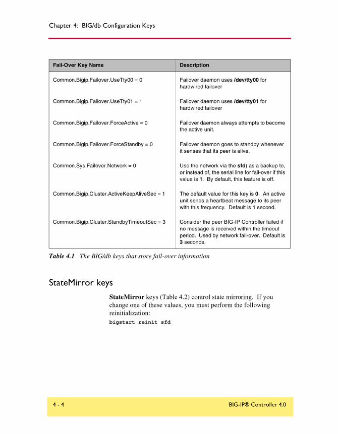
Chapter 4: BIG/db Configuration Keys
StateMirror keysStateMirror keys (Table 4.2) control state mirroring. If you change one of these values, you must perform the following reinitialization:bigstart reinit sfd
Common.Bigip.Failover.UseTty00 = 0 Failover daemon uses /dev/tty00 for hardwired failover
Common.Bigip.Failover.UseTty01 = 1 Failover daemon uses /dev/tty01 for hardwired failover
Common.Bigip.Failover.ForceActive = 0 Failover daemon always attempts to become the active unit.
Common.Bigip.Failover.ForceStandby = 0 Failover daemon goes to standby whenever it senses that its peer is alive.
Common.Sys.Failover.Network = 0 Use the network via the sfd) as a backup to, or instead of, the serial line for fail-over if this value is 1. By default, this feature is off.
Common.Bigip.Cluster.ActiveKeepAliveSec = 1 The default value for this key is 0. An active unit sends a heartbeat message to its peer with this frequency. Default is 1 second.
Common.Bigip.Cluster.StandbyTimeoutSec = 3 Consider the peer BIG-IP Controller failed if no message is received within the timeout period. Used by network fail-over. Default is 3 seconds.
Fail-Over Key Name Description
Table 4.1 The BIG/db keys that store fail-over information
4 - 4 BIG-IP® Controller 4.0

Supported BIG/db configuration keys
State Mirroring Key Name Description
Common.Bigip.StateMirror.DbgFile File into which debug information is written, required if debug level is specified (below).
Common.Bigip.StateMirror.DbgLevel = 0 The debug level is composed of the following options:
1 - log reads and writes
2 - log connection attempts and results
4 - log state changes
8 - open log files in append mode, the default is to truncate the files when opening.
The debug level is zero by default.
Common.Bigip.StateMirror.NoGC = 0 By default, state mirroring causes mirrored data structures to be deleted when it receives a new connection.
This key is brought up to date by the controller’s peer. This can cause a delay if the system is absolutely loaded. Turning off the GC is provided as an option.
Common.Bigip.StateMirror.ActiveFile Enables writing of data from the active unit's kernel into the ActiveFile file. This data file can be read with the sfread program.
Common.Bigip.StateMirror.StandbyFile Enables writing of standby data into the StandBy file. This data file can be read with the sfread program.
Common.Bigip.StateMirror.Username IP address of this BIG-IP Controller. By default sfd uses the first internal interface in the list returned by the bigapi_quer_children BIGapi command. Set this when using multiple NICs.
Common.Bigip.StateMirror.PeerListenPort = 1028 Port on which the BIG-IP Controller listens for connections from the active unit. Default is 1028.
Table 4.2 The BIG/db keys that store state mirroring information
Reference Guide 4 - 5

Chapter 4: BIG/db Configuration Keys
Using Gateway Pinger keysThe GatewayPinger keys (Table 4.3) control the gateway failsafe pinger. If you change one of these values, you must reinitialize the system as follows:bigstart reinit bigd
The following table lists the Gateway Pinger keys.
Bigd keys
The Bidgd keys (Table 4.4) control the health monitors. If you change one of these values, you must re-initialize the system as follows:bigstart reinit bigd
Local.Bigip.StateMirror.Ipaddr IP address of this BIG-IP Controller.
Local.Bigip.StateMirror.PeerIpaddr IP address of this BIG-IP Controller’s peer controller. A value is required.
Gateway Pinger Key Name Description
Local.Bigip.GatewayPinger.Ipaddr = 0.0.0.0
Local.Pinger.alias=Local.Bigip.GatewayPinger.Ipaddr
IP address or host name of the gateway router for the BIG-IP Controller
Local.Bigip.GatewayPinger.Pinginterval = 0 Ping interval of this BIG-IP Controller gateway pinger
Local.Bigip.GatewayPinger.Timeout = 0 Timeout of the BIG-IP Controller gateway pinger
Table 4.3 The BIG/db keys that store gateway pinger information
State Mirroring Key Name Description
Table 4.2 The BIG/db keys that store state mirroring information
4 - 6 BIG-IP® Controller 4.0

Supported BIG/db configuration keys
Bigd Key Name Description
Common.Bigip.Bigd.Verbose = 0 Set to non-zero to cause bigd to generate output to debug file.
Common.Bigip.Bigd.SimulatePings = 0 Set to non-zero to cause bigd to generate pings but not report results to the kernel.
Common.Bigip.Bigd.RecvMatchAll = 0 Set to non-zero to cause bigd to allow any response from the node as a receive match.
Common.Bigip.Bigd.NodePingOff = 0 Set to non-zero to turn off (noisy) bigd node pings. Service pings are still enabled.
Common.Bigip.Bigd.NodePingTcp = 0 Set non-zero so that gateway pinger uses tcp pings rather than icmp pings. This will be going away.
Common.Bigip.Bigd.HostLookup = 0 Set to non-zero to allow bigd to do host lookups.
Common.Bigip.Bigd.DbgFile = "/var/log/bigdlog.<bigd_pid>"
Open a debug output (log) file for bigd.
Table 4.4 The BIG/db keys that store bigd information
Reference Guide 4 - 7

Chapter 4: BIG/db Configuration Keys
Other keys
Table 4.5 lists other keys contained in BIG/dba, including the Akamai proxy key for the content converter, the Realserver, WMI, and SNMPDCA agent keys for dynamic ration load balancing, and the CORBA keys.
Key Names Description
Common.Bigip.Proxy.AkamaiConfigFile=/etc/config/akamai.conf
The default configuration file to use with a proxy when Akamaization is enabled.
Common.Bigip.HttpAgents.WMI.LogEnabled = "true"
Common.Bigip.HttpAgents.RealServer.LogEnabled = "true"
Common.Bigip.SNMPDCA.LogEnabled = "true"
Open a debug output file for each of the respective monitors
# when set to "true" or "yes"
Common.Bigip.CORBA.IIOPPort ="683" Default CORBA IIOP port used for LINK-IT BIG/api
Common.Bigip.CORBA.SSLPort ="684" Default CORBA IIOP SSL port used for LINK-IT BIG/api
Common.Bigip.CORBA.AddrResolveNumeric="true" Set to "true" causes the CORBA portal to resolve client addresses numerically
Common.Bigip.CORBA.IIOPPort ="683" Default CORBA IIOP port used for LINK-IT BIG/api
Table 4.5 Other BIG/db keys
4 - 8 BIG-IP® Controller 4.0
5
Configuration Files

File Description
/config/bigip.conf Stores virtual server and node definitions and settings, including node ping settings, the load balancing mode, and NAT and SNAT settings.
/config/bigip_base.conf Stores BIG-IP Controller self IP addresses and VLAN and interface configurations.
/config/bigip.license Stores authorization information for the BIG-IP Controller.
/etc/bigconf.conf Stores the user preferences for the Configuration utility.
/config/bigconfig/openssl.conf This file holds the configuration information for how the SSL library interacts with browsers, and how key information is generated.
/config/user.db This is the location of the BIG/db database. This database holds various configuration information.
/config/bigconfig/httpd.conf The main configuration file for the webserver.
//config/bigconfig/users The webserver password file. Contains the user names and passwords of the people permitted to access whatever is provided by the webserver.
/etc/hosts Stores the hosts table for the BIG-IP Controller.
/etc/hosts.allow Stores the IP addresses of workstations that are allowed to make administrative shell connections to the BIG-IP Controller.
/etc/netstart Stores basic system start up settings.
/etc/ipfw.conf Stores IP filter settings.
/etc/rateclass.conf Stores rate class definitions.
/etc/ipfwrate.conf Stores IP filter settings for filters that also use rate classes.
/etc/snmpd.conf Stores SNMP configuration settings.
Reference Guide 5 - 1

Chapter 5: Configuration Files
/etc/rc.sysctl Stores the default UNIX and the BIG-IP Controller sysctl variables.
/etc/irs.conf Controls information retrieval functions in the C library.
/etc/login.conf UNIX system file, modified for the BIG-IP Controller.
/etc/bigstart/rc UNIX system startup script, modified for the BIG-IP Controller.
/etc/sshd_config This is the configuration file for the secure shell server (SSH). It contains all the access information for people trying to get into the system via SSH.
/etc/wideip.conf This is a 3-DNS Controller configuration file. For more information, please refer to the documentation for that product.
/VENDOR This file contains information describing F5 Networks. It includes the company name, a common name, contact information, and the text of the licensing agreement for the software.
/VERSION Contains the name of the product, the number, and the access rights (BIG-IP 3.3 HA, for example).
/usr/contrib/bin/ssh-askpass This is the external program used by the SSH configuration utility to ask the user for his password from an X-windows system. It allows SSH to connect to a remote site, or generate a PPKey pair, in a secure manner.
/var/f5/httpd/conf/cert.conf The information for the public key/private key certification infrastructure for the webserver.
File Description
5 - 2 BIG-IP® Controller 4.0

Glossary

Glossary
Any IP Traffic
Any IP Traffic is a feature of the BIG-IP Controller that allows it to load balance protocols other than TCP and UDP.
ARL (Akamai Resource Locator)
A URL that is modified to point to content on the Akamai Freeflow NetworkTM. In content conversion (Akamaization), the URL is converted to an ARL, which retrieves the resource from a geographically nearby server on the Akamai Freeflow Network for faster content delivery.
BIG-IP active unit
In a redundant system, the BIG-IP active unit is the controller that currently load balances connections. If the active unit in the redundant system fails, the standby unit assumes control and begins to load balance connections.
BIG-IP web server
The BIG-IP web server runs on a BIG-IP Controller and hosts the Configuration utility.
bigpipe
The bigpipe utility provides command line access to the BIG-IP Controller.
BIG/stat
BIG/stat is a statistical monitoring utility that ships on the BIG-IP Controller. This utility provides a snap-shot of statistical information.
BIG/top
BIG/top is a statistical monitoring utility that ships on the BIG-IP Controller. This utility provides real-time statistical information.
Reference Guide Glossary - 1
Glossary
big3d
The big3d utility is a monitoring utility that collects metrics information about paths between a BIG-IP Controller and a specific local DNS server. The big3d utility runs on BIG-IP Controllers and it forwards metrics information to 3-DNS Controllers.
BIND (Berkeley Internet Name Domain)
BIND is the most common implementation of DNS, which provides a system for matching domain names to IP addresses.
cacheable content determination
Cacheable content determination is a process that determines the type of content you cache on the basis of any combination of elements in the HTTP header.
cacheable content expression
The cacheable content expression determines, based on evaluating variables in the HTTP header of the request, whether a BIG-IP Cache Controller directs a given request to a cache server or to an origin server. Any content that does not meet the criteria in the cacheable content expression is deemed non-cacheable.
cache_pool
The cache_pool specifies a pool of cache servers to which requests are directed in a manner that optimizes cache performance. The BIG-IP Cache Controller directs all requests bound for your origin server to this pool, unless you have configured the hot content load balancing feature and the request is for hot (frequently requested) content. See also hot and origin server.
chain
A chain is a series of filtering criteria used to restrict access to an IP address. The order of the criteria in the chain determines how the filter is applied, from the general criteria first, to the more detailed criteria at the end of the chain.
Glossary - 2 BIG-IP® Controller 4.0

Glossary
content affinity
Content affinity ensures that a given subset of content remains associated with a given cache server to the maximum extent possible, even when cache servers become unavailable, or are added or removed. This feature also maximizes efficient use of cache memory.
content converter gateway
A content converter gateway is a gateway for converting URLs to ARLs. See also ARL.
content demand status
The content demand status is a measure of the frequency with which content in a given hot content subset is requested over a given hit_period. Content demand status is either hot, in which case the number of requests for content in the hot content subset during the most recent hit_period has exceeded the hot_threshold, or cool, in which case the number of requests during the most recent hit period is less than the cool_threshold. See also cool, cool_threshold, hit_period, hot, hot content subset, and hot_threshold.
content_hash_size
Specifies the number of units, or hot content subsets, into which the content is divided when determining whether content is hot or cool. The requests for all content in a given subset are summed, and a state (hot or cool) is assigned to each subset. The content_hash_size should be within the same order of magnitude as the actual number of requests possible. For example, if the entire site is composed of 500,000 pieces of content, a content_hash_size of 100,000 is typical.
If you specify a value for hot_pool, but do not specify a value for this variable, the cache statement uses a default hash size of 10 subsets. See also cool, hot, and hot content subset.
Reference Guide Glossary - 3

Glossary
content stripes
In products that support caching, content stripes are cacheable content subsets distributed among your cache servers.
cookie persistence
Cookie persistence is a mode of persistence you can configure on the BIG-IP Controller where the controller stores persistent connection information in a cookie.
cool
Cool describes content demand status when you are using hot content load balancing. See also content demand status, hot, and hot content load balancing.
cool threshold
The cool threshold specifies the maximum number of requests for given content that will cause that content to change from hot to cool at the end of the hit period.
If you specify a variable for hot_pool, but do not specify a value for this variable, the cache statement uses a default cool_threshold of 10 requests. See also cool, hit_period, and hot.
default VLANs
The BIG-IP Controller is configured with two default VLANs, one for each interface. One default VLAN is named internal and one is named external. See also VLAN.
default wildcard virtual server
A default wildcard virtual server has an IP address and port number of 0.0.0.0:0. or *:* or "any":"any". This virtual server accepts all traffic which does not match any other virtual server defined in the configuration.
Glossary - 4 BIG-IP® Controller 4.0
Glossary
dynamic load balancing
Dynamic load balancing modes use current performance information from each node to determine which node should receive each new connection. The different dynamic load balancing modes incorporate different performance factors such as current server performance and current connection load.
Dynamic Ratio load balancing mode
Dynamic Ratio mode is like Ratio mode (see Ratio mode), except that ratio weights are based on continuous monitoring of the servers and are therefore continually changing. Dynamic Ratio load balancing may currently be implemented on RealNetworks RealServer platforms, on Windows platforms equipped with Windows Management Instrumentation (WMI), or on a server equipped with either the UC Davis SNMP agent or Windows 2000 Server SNMP agent.
dynamic site content
Dynamic site content is site content that is automatically generated each time a user accesses the site. Examples are current stock quotes or weather satellite images.
EAV (Extended Application Verification)
EAV is a health check that verifies an application on a node by running that application remotely. EAV health check is only one of the three types of health checks available on a BIG-IP Controller. See also health check, health monitor and external monitor.
ECV (Extended Content Verification)
ECV is a health check that allows you to determine if a node is up or down based on whether the node returns specific content. ECV health check is only one of the three types of health checks available on a BIG-IP Controller. See also health check.
Reference Guide Glossary - 5

Glossary
external monitor
A user-supplied health monitor. See also, health check, health monitor.
external VLAN
The external VLAN is a default VLAN on the BIG-IP Controller. In a basic configuration, this VLAN has the administration ports locked down. In a normal configuration, this is typically a VLAN on which external clients request connections to internal servers.
F-Secure SSH
F-Secure SSH is an encryption utility that allows secure shell connections to a remote system.
fail-over
Fail-over is the process whereby a standby unit in a redundant system takes over when a software failure or a hardware failure is detected on the active unit.
fail-over cable
The fail-over cable directly connects the two controller units together in a redundant system.
Fastest mode
A dynamic load balancing mode that bases connection distribution on which server currently exhibits the fastest response time to node pings.
FDDI (Fiber Distributed Data Interface)
FDDI is a multi-mode protocol used for transmitting data on optical-fiber cables at speeds up to 100 Mbps.
Glossary - 6 BIG-IP® Controller 4.0

Glossary
First-Time Boot utility
The First-Time Boot utility walks you through the initial system configuration process. You can run the First-Time Boot utility from either the command line or the Configuration utility start page.
floating self IP address
An additional self IP address for a VLAN that serves as a shared address by both units of a BIG-IP Controller redundant system.
forward proxy caching
Forward proxy caching is a configuration in which a BIG-IP Cache Controller redundant system uses content-aware traffic direction to enhance the efficiency of an array of cache servers storing Internet content for internal users.
health check
A health check is a BIG-IP Controller feature that determines whether a node is up or down. Health checks are implemented through health monitors. See also health monitor, ECV, EAV, and external monitor.
health monitor
A health monitor checks a node to see if it is up and functioning for a given service. If the node fails the check, it is marked down. Different monitors exist for checking different services. See also health check, EAV, ECV, and external monitor.
hit period
The hit period specifies the period, in seconds, over which to count requests for particular content before determining whether to change the state (hot or cool) of the content.
If you specify a value for hot_pool, but do not specify a value for this variable, the cache statement uses a default hit_period of 10 seconds. See also cool, hot, and hot_pool.
Reference Guide Glossary - 7

Glossary
host
A host is a network server that manages one or more virtual servers that the 3-DNS Controller uses for load balancing.
hot
Hot is a term used to define frequently requested content based on the number of requests in a given time period for a given hot content subset. See also hot content subset.
hot pool
A hot pool is a designated group of cache servers to which requests are load balanced when the requested content is hot. If a request is for hot content, the BIG-IP Cache Controller redundant system directs the request to this pool.
hot content load balancing
Identifies hot or frequently requested content on the basis of number of requests in a given time period for a given hot content subset. A hot content subset is different from, and typically smaller than, the content subsets used for content striping. Requests for hot content are redirected to a cache server in the hot pool, a designated group of cache servers. This feature maximizes the use of cache server processing power without significantly affecting the memory efficiency gained by cacheable content determination. See also hot, hot content subset, and hot pool.
hot content subset
A hot content subset is different from, and typically smaller than, the content subsets used for cacheable content determination. This is created once content has been determined to be hot and is taken or created from the content subset. See also cacheable content determination.
hot threshold
The hot threshold specifies the minimum number of requests for content in a given hot content subset that will cause that content to change from cool to hot at the end of the period.
Glossary - 8 BIG-IP® Controller 4.0

Glossary
If you specify a value for hot_pool, but do not specify a value for this variable, the cache statement uses a default hot_threshold of 100 requests. See also cool, hot, hot content subset, and hot pool.
HTTP redirect
An HTTP redirect sends an HTTP 302 Object Found message to clients. You can configure a pool with an HTTP redirect to send clients to another node or virtual server if the members of the pool are marked down.
ICMP (Internet Control Message Protocol)
An Internet communications protocol used to determine information about routes to destination addresses, such as virtual servers managed by BIG-IP Controllers and 3-DNS Controllers.
intelligent cache population
Intelligent cache population allows caches to retrieve content from other caches in addition to the origin web server. Use this feature when working with non-transparent cache servers that can receive requests destined for the cache servers themselves. Intelligent cache population minimizes the load on the origin web server and speeds cache population. See also non-transparent cache server and transparent cache server.
interface
The physical port on a BIG-IP Controller. See also link.
IPSEC
IPSEC (Internet Security Protocol) is a communications protocol that provides security for the network layer of the Internet without imposing requirements on applications running above it.
iQuery
A UDP based protocol used to exchange information between BIG-IP Controllers and 3-DNS Controllers. The iQuery protocol is officially registered for port 4353.
Reference Guide Glossary - 9

Glossary
internal VLAN
The internal VLAN is a default VLAN on the BIG-IP Controller. In a basic configuration, this VLAN has the administration ports open. In a normal configuration, this is a network interface that handles connections from internal servers.
last hop
A last hop is the final hop a connection took to get to the BIG-IP Controller. You can allow the BIG-IP Controller to determine the last hop automatically to send packets back to the device from which they originated. You can also specify the last hop manually by making it a member of a last hop pool.
Least Connections mode
A dynamic load balancing mode that bases connection distribution on which server currently manages the fewest open connections.
link
A link is a physical interface on the BIG-IP Controller connected to another physical interface in a network.
link aggregation
The link aggregation feature allows you to combine a number of links together to act as one interface.
load balancing mode
A particular method of determining how to distribute connections across an array.
loopback adapter
A loopback adapter is a software interface that is not associated with an actual network card. The nPath routing configuration requires you to configure loopback adapters on servers.
Glossary - 10 BIG-IP® Controller 4.0
Glossary
MAC (Media Access Control)
MAC is a protocol that defines the way workstations gain access to transmission media, and is most widely used in reference to LANs. For IEEE LANs, the MAC layer is the lower sublayer of the data link layer protocol.
MAC address
A MAC address is used to represent hardware devices on an Ethernet network.
member
Member is a reference to a node when it is included in a particular pool. Pools typically include multiple member nodes.
minimum active members
The number of members that must be active in a priority group in order for the BIG-IP Controller to send its requests to that group. If the number of active members falls below this number, requests are sent to the next highest priority group (the priority group with the next lowest priority number).
mirroring
A feature on the BIG-IP Controller that preserves connection and persistence information in a BIG-IP Controller redundant system.
miss request
When a cache does not have requested content and cannot respond to the request, it is called a miss request.
monitor
The BIG-IP Controller uses monitors to determine whether nodes are up or down. There are several different types of monitors and they use various methods to determine the status of a server or service.
Reference Guide Glossary - 11

Glossary
monitor destination IP address or IP address:port
The monitor destination IP address or address: port for a user defined monitor is used mainly for setting up a node alias for the monitor to check. All nodes associated with that monitor will be marked down if the alias node (destination IP address:port) is marked down. See also node alias.
monitor instance
You create a monitor instance when a health monitor is associated with a node, node address, or port. It is the monitor instance that actually performs the health check, not the monitor.
monitor template
A system-supplied health monitor that is used primarily as a template to create user-defined monitors but in some cases can be used as is. The BIG-IP Controller includes a number of monitor templates, each specific to a service type, for example, HTTP and FTP. The template has a template type that corresponds to the service type and is usually the name of the template.
named
Named is the name server daemon, which manages domain name server software.
NAT (Network Address Translation)
A NAT is an alias IP address that identifies a specific node managed by the BIG-IP Controller to the external network.
node
A node is a specific combination of an IP address and port (service) number associated with a server in the array that is managed by the BIG-IP Controller.
Glossary - 12 BIG-IP® Controller 4.0

Glossary
node address
A node address is the IP address associated with one or more nodes. This IP address can be the real IP address of a network server, or it can be an alias IP address on a network server.
node alias
A node alias is a node address that the BIG-IP Controller uses to verify the status of multiple nodes. When the BIG-IP Controller uses a node alias to check node status, it pings the node alias. If the BIG-IP Controller receives a response to the ping, it marks all nodes associated with the node alias as up. If the controller does not receive a response to the ping, the it marks all nodes associated with the node alias as down.
node port
The port number or service name that is hosted by a specific node.
node status
Node status indicates whether a node is up and available to receive connections, or down and unavailable. The BIG-IP Controller uses the node ping and health check features to determine node status.
non-cacheable content
Content that is not identified in the cacheable content condition part of a cache rule statement.
non-transparent cache server
Cache servers that can receive requests that are destined for the cache servers themselves.
origin server
The web server on which all original copies of your content reside.
Reference Guide Glossary - 13
Glossary
origin pool
Specifies a pool of servers that contain original copies of all content. Requests are load balanced to this pool when any of the following is true: the requested content is not cacheable, no cache server is available, or the BIG-IP Cache Controller redundant system is redirecting a request from a cache server that did not have the requested content.
Observed mode
A dynamic load balancing mode that bases connection distribution on a combination of two factors: the server that currently hosts the fewest connections and has the fastest response time.
performance monitor
A performance monitor gathers statistics and checks the state of a target device.
persistence
A series of related connections received from the same client, having the same session ID. When persistence is turned on, a controller sends all connections having the same session ID to the same node instead of load balancing the connections.
pool
A pool is composed of a group of network devices (called members). The BIG-IP Controller load balances requests to the nodes within a pool based on the load balancing method and persistence method you choose when you create the pool or edit its properties.
port
A port is can be represented by a number that is associated with a specific service supported by a host. Refer to the Services and Port Index for a list of port numbers and corresponding services.
Glossary - 14 BIG-IP® Controller 4.0

Glossary
port-specific wildcard virtual server
A port-specific wildcard virtual server is a wildcard virtual server that uses a port number other than 0.
Predictive mode
A dynamic load balancing mode that bases connection distribution on a combination of two factors: the server that currently hosts the fewest connections, and also has the fastest response time. Predictive mode also ranks server performance over time, and passes connections to servers which exhibit an improvement in performance rather than a decline.
rate class
You create a rate filter from the Configuration utility or command line utility. When you assign a rate class to a rate filter, a rate class determines the volume of traffic allowed through a rate filter. See also rate filter.
rate filterRate filters consist of a basic filter with a rate class. Rate filters are a type of extended IP filter. They use the same IP filter method, but they apply a rate class, which determines the volume of network traffic allowed through the filter. See also rate class.
ratio
A ratio is a parameter that assigns a weight to a virtual server for load balancing purposes.
Ratio mode
The Ratio load balancing mode distributes connections across an array of virtual servers in proportion to the ratio weights assigned to each individual virtual server.
receive expression
A receive expression is the text string that the BIG-IP Controller looks for in the web page returned by a web server during an extended content verification (ECV) health check.
Reference Guide Glossary - 15

Glossary
redundant system
Redundant system refers to a pair of controllers that are configured for fail-over. In a redundant system, there are two controller units, one running as the active unit and one running as the standby unit. If the active unit fails, the standby unit takes over and manages connection requests.
RFC 1918 addresses
An address that is within the range of non-routable addresses described in the IETF RFC 1918.
remote administrative IP address
An IP address from which a controller allows shell connections, such as Telnet or SSH.
remote server acceleration
A configuration in which a BIG-IP Cache Controller redundant system uses content-aware traffic direction to enhance the efficiency of an array of cache servers that cache content for a remote web server.
Round Robin mode
A static load balancing mode that bases connection distribution on a set server order. Round Robin mode sends a connection request to the next available server in the order.
self IP address
Self IP addresses are the IP addresses owned by the BIG-IP Controller that you use to access the internal and external VLANs.
send string
A send string is the request that the BIG-IP Controller sends to the web server during an extended content verification (ECV) health check.
Glossary - 16 BIG-IP® Controller 4.0

Glossary
service
Service refers to services such as TCP, UDP, HTTP, and FTP.
SNAT (Secure Network Address Translation)
A SNAT is a feature you can configure on the BIG-IP Controller. A SNAT defines a routable alias IP address that one or more nodes can use as a source IP address when making connections to hosts on the external network.
SNAT automap
This feature allows the BIG-IP Controller to perform a SNAT automatically on any connection that is coming from the controller’s internal VLAN. It is easier to use than traditional SNATs and solves certain problems associated with the latter.
SNMP (Simple Network Management Protocol)
SNMP is the Internet standard protocol, defined in STD 15, RFC 1157, developed to manage nodes on an IP network.
sod (switch over daemon)
The sod is a daemon that controls the fail-over process in a redundant system.
source processing
Source processing means that the interface rewrites the source of an incoming packet.
SSL gateway
A gateway for decrypting HTTP requests to an HTTP server and encrypting the reply.
standby unit
A controller in a redundant system that is always prepared to become the active unit if the active unit fails.
Reference Guide Glossary - 17
Glossary
stateful site content
Content that maintains dynamic information for clients on an individual basis and is commonly found on e-commerce sites. For example, a site that allows a user to fill a shopping cart, leave the site, and then return and purchase the items in the shopping cart at a later time has stateful site content which retains the information for that client's particular shopping cart.
static load balancing modes
Static load balancing modes base connection distribution on a pre-defined list of criteria; it does not take current server performance or current connection load into account.
static site content
A type of site content that is stored in HTML pages, and changes only when an administrator edits the HTML document itself.
sticky mask
A sticky mask is a special IP mask that you can configure on the BIG-IP Controller. This mask optimizes sticky persistence entries by grouping more of them together.
tagged VLAN
You can define any interface as a member of a tagged VLAN. You can create a list of VLAN tags or names for each tagged interface.
transparent cache server
A transparent cache server can intercept requests destined for a web server, but cannot receive requests.
transparent node
A transparent node appears as a router to other network devices, including the BIG-IP Controller.
Glossary - 18 BIG-IP® Controller 4.0

Glossary
trunk
A trunk is a combination of two or more interfaces and cables configured as one link. See also link aggregation.
user-defined monitor
A user-defined monitor is a custom monitor configured by a user, based on a system-supplied monitor template. For some monitor types, you must create a user-defined monitor in order to use them. For all monitor types, you must create a user-defined monitor to change system supplied monitor default values.
virtual address
A virtual address is an IP address associated with one or more virtual servers managed by the BIG-IP Controller.
virtual port
A virtual port is the port number or service name associated with one or more virtual servers managed by the BIG-IP Controller. A virtual port number should be the same TCP or UDP port number to which client programs expect to connect.
virtual server
Virtual servers are a specific combination of virtual address and virtual port, associated with a content site that is managed by a BIG-IP Controller or other type of host server.
VLAN
VLAN stands for virtual local area network. A VLAN is a logical grouping of network devices. You can use a VLAN to logically group devices that are on different network segments.
VLAN name
A VLAN name is the symbolic name used to identify a VLAN. For example, you might configure a VLAN named marketing, or a VLAN named development. See also VLAN.
Reference Guide Glossary - 19

Glossary
watchdog timer card
A watchdog timer card is a hardware device that monitors the BIG-IP Controller for hardware failure.
wildcard virtual server
A virtual server that uses an IP address of 0.0.0.0, * or "any". A wildcard virtual server accepts connection requests for destinations outside of the local network. Wildcard virtual servers are included only in Transparent Node Mode configurations.
Glossary - 20 BIG-IP® Controller 4.0

Index

Index
/config/bigip.conf 2-68/config/bigip.conf file 2-65/etc/services file 1-82, 2-71-? command 2-43-DNS module
NameSurfer 3-113-DNS software module Intro-3
Aaccess rates 1-179active units 1-153active-active mode
configuring an additional floating self IP address 1-167
configuring servers 1-168synchronizing configuration 1-171transitioning from active/standby 1-172understanding system fail-over. See
system fail-overupdating fail-over daemon 1-171updating the fail-over daemon 1-171
address translation. See NATs and SNATsAdministrator Kit, description Intro-2Any IP (any_ip property) 2-96ARP 1-155ASCII characters
and constant operands 1-43assigning interfaces to VLANs 3-7
Bbase configuration utilities 3-1BIG/db keys
fail-over 4-3gateway pinger 4-6state mirroring 4-5
BIG/db parametersfor active-active mode 1-166, 1-174
BIG-IP Cache Controller, selecting 3-4BIG-IP Controller product family Intro-10BIG-IP Controllers
base configuration utilities 3-1BIG-IP FireGuard, selecting 3-4
BIG-IP Load Balancer, selecting 3-4bigip.bonfire_compatibility_mode variable 2-9bigip.fastest_max_idle_time variable 2-9bigip.improved_fastest 2-11bigip.memory_reboot_percent variable 2-11bigip.open_3dns_lockdown_ports variable 2-9, 2-11bigip.open_ftp_ports variable 2-12bigip.open_rsh_ports variable 2-13bigip.open_ssh_port variable 2-13bigip.open_telnet_port variable 2-12bigip.persist_map_proxies 2-13bigip.persist_on_any_port_same_virtual variable 2-15bigip.persist_on_any_virtual variable 2-15bigip.persist_time_used_as_limit variable 2-14bigip.verbose_log_level variable 2-15bigip.virtualnoarp variable 2-16bigip.webadmin_port variable 2-16bigpipe commands 2-1–2-104
and active-active mode 1-175displaying active data 1-175mirroring 1-158snat 1-53
bigpipe ratio command 1-11bigpipe utility Intro-2bigtop utility Intro-2bitmask 1-89, 2-37broadcast 1-67, 2-90browser, supported versions Intro-2
Ccache rule
defined 1-40cache statement
defined 1-49syntax 1-50
client IP address variable 1-42See also client_addr variable
client IP addressesand rules 1-40
client_addr variable 1-43, 1-44
Reference Guide Index - 1

Index
config3-DNS module options 3-11NTP support 3-11
config combo command 3-12config command 2-9config dns utility 3-13config ftpd utility 3-14config httpd utility 3-15config password utility 3-16config redundant utility 3-17config rshd utility 3-19config sshd utility 3-20config timezone utility 3-22config utility 3-3config_rshd utility 3-21config_sshd utility 3-18Configuration 3-18configuration files 5-1configuration keys
BIG/db 4-1–4-8configuration settings 2-68Configuration utility 3-18
configuring a pool 1-2Configuration utility, web-based Intro-1configurations
clearing memory 2-64synchronizing 2-5
conn command 2-7connection limits
for node addresses 1-80for nodes 1-79, 2-41for ports 1-82, 2-71for SNAT addresses 2-77for virtual servers 1-68, 2-92
connection requests 1-61connection timeout 1-84, 2-72, 2-73connections 1-72
administrative 3-10client 2-7FTP 2-12long-lived 1-157Telnet 2-12virtual server 1-67, 2-90
constant operand types 1-43
content converterconfiguring 1-74
content serversdefault route 3-7
controller synchronization 1-153controllers
active and standby 1-157setting preferred active unit 1-164
cookie names 1-46cookies 1-180
Ddefault route 1-155default route configuration 3-5default routers 1-101destination address affinity 1-32destination IP addresses
as filter criteria 1-178DNS configuration
DNS forwarding proxy 3-10, 3-13dynamic ratio mode 1-6
configuring RealServer for 1-12configuring servers for 1-12configuring SNMP for 1-19configuring WMI for 1-16
Eexpressions
listed 1-44parts of 1-43See also logical expressions
external interfaces 1-88, 2-37external monitor 1-132external network. See external interfacesexternal VLANs 3-8
Ffailover command 2-8fail-over process 1-157fail-safe
features of 1-160fail-safe settings 1-152–1-156
Index - 2 BIG-IP® Controller 4.0

Index
fallback host. See HTTP redirectfastest mode 1-7filter types 1-177, 1-179filters
defined 1-177First-Time Boot utility 3-3
defined Intro-1floating self IP address 3-7floating self IP aliases
configuring additional 1-167forwarding virtual servers
configuring 1-98FQDNs 1-46F-Secure SSH client
remote administration Intro-2FTP 2-12ftp monitor 1-128Fully Qualified Domain Names
See FQDNs
Ggateway command 2-10gateway fail-safe 1-160–1-163gateway fail-safe messages 1-163gateway pinger key names 4-6
H-h command 2-17hard-wired fail-over 1-163Hash mode 1-30header_tag_string 1-46health monitor templates
external 1-132ftp 1-128http 1-126https 1-127icmp 1-124imap 1-130ldap 1-131nntp 1-129pop3 1-128radius 1-131
smtp 1-129sql 1-130tcp 1-125tcp_echo 1-124
health monitors 1-2, 1-120, 1-151associating with a node 1-143configuring 1-132logical grouping in 1-147transparent mode in 1-146
-help command 2-17help command 2-4host names
defining 3-5HTTP headers
configuring rules 1-40http monitor 1-126HTTP redirect 1-38, 2-54HTTP request data 1-40
and pool selection 1-40HTTP request string variables
and header data 1-45and rules 1-41as variable operands 1-44replacing 1-44
HTTP request variable names 1-45http_cookie variables 1-46http_header variables 1-46http_host variables 1-46http_method variables 1-45http_uri variables 1-46http_version variables 1-46httpd server 3-15httpd.conf 3-9https monitor 1-127
Iicmp monitor 1-124Idle connection timeout 1-102if statements 1-42imap monitor 1-130Insert mode 1-26interface cards 1-155interface command 2-18
Reference Guide Index - 3

Index
interface media typesconfiguring interface media settings 3-6
interface naming convention 1-115internal interfaces 1-87internal network. See internal interfacesinternal VLANs 3-8IP address notation 1-43IP addresses 2-37
changing 3-9configuring default route 3-5configuring fail-over 3-6defining Intro-1destination 1-61for clients 1-34See also client IP addresses
IP forwarding 1-82setting up 1-100–1-101system control variables 1-101
IP packet filtersconfiguring 1-178in the F5 Configuration utility 1-178
IP packetsand rule evaluation 1-43
Lldap monitor 1-131least connections mode 1-7LED indicators 3-7link aggregation and fail-over 1-118literals. See constant operandsload balancing
configuring Intro-1monitoring Intro-1onset 1-41transparent nodes 1-61
load balancing modesdynamic ratio 1-6fastest 1-7least connections 1-7observed 1-7predictive 1-8Ratio 2-62ratio 1-6
round robin 1-5, 1-6setting 1-9
load balancing pool selectionand client IP address 1-41and HTTP request data 1-40
load balancing pools 2-45, 2-89and client address variables 1-42defining 1-2referencing by servers and rules 1-40, 1-47selecting via use statements 1-42
load balancing rules 2-89logging 2-16, 2-84logical expressions
listed 1-45logical operators
listed 1-45
MMAC addresses 1-111, 1-112, 2-102MAC masquerade 1-111maint command 2-20masked dot notation
and constant operands 1-43media access control. See MAC addressesmessages
gateway fail-safe 1-163MIB. See SNMP MIBmirroring
described 1-157–1-160global 1-158
mirroring commands 1-158monitor command 2-23monitoring, command-line utilities Intro-2
N-n command 2-36nat command 1-87–1-90, 2-37NATs 1-87
defining 1-88netmask 1-67, 1-89, 2-37, 2-90network adapters 3-7
Index - 4 BIG-IP® Controller 4.0

Index
network address translation (NAT). See nat commandnetwork address translations. See NATsnetwork interface cards. See NICNetwork Time Protocol (NTP) 3-11network traffic 1-155
and HTTP requests 1-41and IP packet filters 1-177and ITC (intelligent traffic control) 1-180identifying 1-180
network virtual server 1-64network-based fail-over 1-163nntp monitor 1-129node addresses
and ratio weights 1-11–1-12connection limits 1-80ratio weights 2-62
node command 1-78–1-81, 2-40–2-44node configuration 1-87–1-101nodes
connection limits 1-79, 2-41connections 2-37
Oobserved mode 1-7open FTP ports 2-12openssl.conf 3-9operands 1-43operators 1-43, 1-45operators. See relational operators
Ppackets
forwarding and rejecting 1-177Passive mode 1-29persistence 2-13, 2-14, 2-15
advanced options 1-23–1-38and mirroring 1-157–1-160conditions for 1-35for connections 1-72See also destination address affinitySee also device persistence
See also HTTP cookie persistenceSee also simple persistenceSee also SSL persistenceSSL 1-23using persist mask 1-34
pool command 1-2–1-39, 2-45–2-54pool selection 1-40, 1-41pools 1-25
persistence 1-23pools. See load balancing poolspop3 monitor 1-128ports
RSH 2-9, 2-13translation properties 1-68, 2-92wildcard 1-61–1-64
predicates 1-43predictive mode 1-8Priority based member activation 1-8priority levels
setting 1-11procedures
configuring gateway fail-safe 1-161configuring NATs 1-88configuring network fail-over 1-163configuring persistence for virtual
servers 1-25configuring SNAT address mappings 1-93configuring SNAT global properties 1-91configuring SSL persistence 1-24defining virtual server mappings 1-62enabling active-active mode 1-167returning to active/standby mode 1-176setting IP forwarding 1-101synchronizing redundant systems 1-171turning off port translation 1-63
product selection 3-4
Rradius monitor 1-131rate classes 1-179, 1-180rate filters 1-179, 1-180rates of access 1-179ratio command 2-62
Reference Guide Index - 5

Index
Ratio mode 2-62ratio mode 1-6ratio weights 2-62, 2-63
setting 1-11RealServer
configuring for dynamic ratio load balancing 1-12
reconfig-httpd utility 3-9redundant system modes 1-165, 1-166, 1-176redundant systems 1-152–1-156
active unit 1-153advanced features of 1-152, 1-176choosing an interface media type 3-6choosing fail-over IP addresses 3-6configuring gateway fail-safe 2-10configuring hop pools 1-69, 2-60, 2-93default mode 1-166displaying unit number 2-83fail-over 2-8fail-safe interfaces 1-156floating self IP address 3-7gateway fail-safe. See gateway fail-safemirroring 1-97, 2-77See also active/standby modeSee also mirroringSee also network-based fail-overselecting unit ID 3-6sharing MAC addresses 1-112, 2-103standby unit 1-153synchronizing 2-5
regular expression stringsand constant operands 1-43
relation expressionsusing HTTP request variables in 1-45
relational operatorslisted 1-44
remote shell. See RSHreset command 2-64Rewrite mode 1-27root password
defining Intro-1root password definition 3-4round robin mode 1-5, 1-6routing table 1-101
RSH 2-13rule behavior 1-40rule command 2-65rule elements
listed and described 1-48, 1-49rule evaluation 1-43rule examples 1-40, 1-54
AOL rule 1-56cache content rule 1-55client IP address and IP protocol 1-41cookie rule 1-54IP protocol specific rule 1-57language rule 1-55
rule statements 1-42rules
and client address variable 1-42configuring 1-49creating 1-47defined 2-65elements 1-49example 1-41listing of 2-67load balancing 2-89load balancing pools 2-65referencing pools 1-47
Ssave command 2-68saving 2-68secure network address translation (SNAT). See snat commandsecure network address translation (SNAT). See SNATssecure shell 2-13, 3-20security
encryption. See encryptionfor web server 3-8
server resource allocation 1-180service checks
troubleshooting 1-138, 2-31service command 2-71–2-73services 1-82
displaying numerically 2-36
Index - 6 BIG-IP® Controller 4.0

Index
FTP configuration 3-21telnet configuration 3-21
Setting the MAC masquerade address 1-117, 2-18simple persistencesmtp monitor 1-129SNAT address mappings, configuring 1-53SNAT automap 1-94snat command 1-53, 1-90–1-97, 2-74SNAT connections
mirroring 1-159SNATs
address mappings 1-92connection limits 1-91defining 1-90–1-93global properties 1-91TCP idle connection timeout 1-91UDP idle connection timeout 1-91
SNMPconfiguring for dynamic ratio load
balancing 1-19SNMP MIB Intro-2sod utility 1-164source IP addresses 1-88SQL Enterprise Manager 1-138, 2-32sql monitor 1-130SQL-based service checks
troubleshooting 1-138, 2-31SQL-based services
and service checks 1-130SSH 2-13SSH client. See F-Secure SSH clientSSL persistence 1-99standby mode 1-164, 1-165standby units 1-153state mirroring key names 4-5statements
for rules 1-42function of 1-42
sticky entries 2-15string variables 1-45subjects 1-43summary command 2-79SYN packets 1-41
synchronization. See controller synchronizationsystem control variables
bigip.persist_map_proxies 2-13system fail-over
disabling automatic fail back 1-173in active-active mode 1-172, 1-174placing back in service 1-173placing in standby mode 1-173
Ttarget IP addresses
See destination IP addressesTCP handshakes
proxying 1-41tcp monitor 1-125TCP SYN packets 1-41tcp_echo monitor 1-124technical support Intro-6test accounts
creating 1-138, 2-32time zone configuration 3-9translation properties 1-68, 2-92transparent mode 1-146transparent network devices 1-59, 1-60transparent nodes 1-61, 1-62trunk 2-81trunk command 1-119, 2-81
Uunit command 2-83URLs
and http_uri variable 1-46US functionality
generating authentication certificates 3-8usage statistics 2-79use statements 1-42utilities Intro-2
bigpipe commands 2-1–2-104First-Time Boot 3-3reconfig-httpd 3-9web-based Configuration utility 3-18
Reference Guide Index - 7

Index
Vvariable names
string variable names 1-45variable operands
and rules 1-43defined 1-43types 1-43
variables 1-43verbose command 2-84virtual addresses
defining a netmask 1-67, 2-90displaying information 1-70, 2-95statistics 1-70, 2-95translation properties 1-68, 2-92
virtual command 1-58–1-70virtual server configuration
referencing rules 1-48See also rules
virtual server mappings 1-35, 1-37defining standard 1-60defining wildcard 1-62–1-64
virtual servers 1-58–1-70additional features 1-72and persistence 1-35configuring 1-58–1-64configuring addresses 1-169configuring hop pools 1-69, 2-60, 2-93configuring load balancing pools 2-89defining standard 1-59defining wildcard 1-59, 1-60–1-64displaying unit number 2-83enabling 1-69, 2-94forwarding 1-88mirroring 1-65, 1-159, 2-93rules 2-66, 2-89
vlan command 2-97VLAN group 1-107VLANs 1-102
creating 1-106external. See external VLANfloating self IP address 3-7internal. See internal VLANtagging 1-108
Wweb administration 2-16web server settings 3-8WMI
configuring for dynamic ratio load balancing 1-16
Index - 8 BIG-IP® Controller 4.0


![MFC‒J870N Windows8 (1) (InternetExplorer Safari ) (2 ...1 ( lan)( lan) ip ip ( ) ip ip lan (1) ip [ ] [ ] [ ] [ok]](https://static.fdocuments.net/doc/165x107/5e71d52e4c8f4929404a3a6d/mfcaj870n-windows8-1-internetexplorer-safari-2-1-lan-lan-ip-ip.jpg)


