Big Blue 400P Big Blue 500 X CE - Rapid Welding · Big Blue 400P Big Blue 500 X CE...
98
Processes Description TIG (GTAW) Welding Stick (SMAW) Welding MIG (GMAW) Welding Engine Driven Welding Generator OM-4421 215 075AC 2011−01 Visit our website at www.MillerWelds.com Flux Cored (FCAW) Welding Air Carbon Arc (CAC-A) Cutting and Gouging File: Engine Drive Big Blue 400P Big Blue 500 X CE R R (Perkins-Powered)
Transcript of Big Blue 400P Big Blue 500 X CE - Rapid Welding · Big Blue 400P Big Blue 500 X CE...

Processes
Description
TIG (GTAW) Welding
Stick (SMAW) Welding
MIG (GMAW) Welding
Engine Driven Welding Generator
OM-4421 215 075AC
2011−01
Visit our website at
www.MillerWelds.com
Flux Cored (FCAW) Welding
Air Carbon Arc (CAC-A)Cutting and Gouging
File: Engine Drive
Big Blue 400PBig Blue 500 X CE
�
�
(Perkins-Powered)

Miller Electric manufactures a full lineof welders and welding related equipment.For information on other quality Millerproducts, contact your local Miller distributor to receive the latest fullline catalog or individual specification sheets. To locate your nearestdistributor or service agency call 1-800-4-A-Miller, or visit us atwww.MillerWelds.com on the web.
Thank you and congratulations on choosing Miller. Now you can getthe job done and get it done right. We know you don’t have time to doit any other way.
That’s why when Niels Miller first started building arc welders in 1929,he made sure his products offered long-lasting value and superiorquality. Like you, his customers couldn’t afford anything less. Millerproducts had to be more than the best they could be. They had to be thebest you could buy.
Today, the people that build and sell Miller products continue thetradition. They’re just as committed to providing equipment and servicethat meets the high standards of quality and value established in 1929.
This Owner’s Manual is designed to help you get the most out of yourMiller products. Please take time to read the Safety precautions. Theywill help you protect yourself against potential hazards on the worksite.
We’ve made installation and operation quickand easy. With Miller you can count on yearsof reliable service with proper maintenance.And if for some reason the unit needs repair,there’s a Troubleshooting section that willhelp you figure out what the problem is. Theparts list will then help you to decide theexact part you may need to fix the problem.Warranty and service information for yourparticular model are also provided.
Miller is the first weldingequipment manufacturer inthe U.S.A. to be registered tothe ISO 9001 Quality SystemStandard.
Working as hard as you do− every power source fromMiller is backed by the mosthassle-free warranty in thebusiness.
From Miller to You
Mil_Thank 2009−09
TABLE OF CONTENTS
SECTION 1 − SAFETY PRECAUTIONS − READ BEFORE USING 1. . . . . . . . . . . . . . . . . . . . . . . . . . . . . . . . .
1-1. Symbol Usage 1. . . . . . . . . . . . . . . . . . . . . . . . . . . . . . . . . . . . . . . . . . . . . . . . . . . . . . . . . . . . . . . . . . . . . . .
1-2. Arc Welding Hazards 1. . . . . . . . . . . . . . . . . . . . . . . . . . . . . . . . . . . . . . . . . . . . . . . . . . . . . . . . . . . . . . . . .
1-3. Engine Hazards 3. . . . . . . . . . . . . . . . . . . . . . . . . . . . . . . . . . . . . . . . . . . . . . . . . . . . . . . . . . . . . . . . . . . . . .
1-4. Hydraulic Hazards 4. . . . . . . . . . . . . . . . . . . . . . . . . . . . . . . . . . . . . . . . . . . . . . . . . . . . . . . . . . . . . . . . . . . .
1-5. Compressed Air Hazards 4. . . . . . . . . . . . . . . . . . . . . . . . . . . . . . . . . . . . . . . . . . . . . . . . . . . . . . . . . . . . . .
1-6. Additional Symbols For Installation, Operation, And Maintenance 5. . . . . . . . . . . . . . . . . . . . . . . . . . . . .
1-7. California Proposition 65 Warnings 6. . . . . . . . . . . . . . . . . . . . . . . . . . . . . . . . . . . . . . . . . . . . . . . . . . . . . .
1-8. Principal Safety Standards 7. . . . . . . . . . . . . . . . . . . . . . . . . . . . . . . . . . . . . . . . . . . . . . . . . . . . . . . . . . . . .
1-9. EMF Information 7. . . . . . . . . . . . . . . . . . . . . . . . . . . . . . . . . . . . . . . . . . . . . . . . . . . . . . . . . . . . . . . . . . . . .
SECTION 2 − CONSIGNES DE SÉCURITÉ − LIRE AVANT UTILISATION 8. . . . . . . . . . . . . . . . . . . . . . . . . .2-1. Signification des symboles 8. . . . . . . . . . . . . . . . . . . . . . . . . . . . . . . . . . . . . . . . . . . . . . . . . . . . . . . . . . . . .
2-2. Dangers relatifs au soudage à l’arc 8. . . . . . . . . . . . . . . . . . . . . . . . . . . . . . . . . . . . . . . . . . . . . . . . . . . . . .
2-3. Dangers existant en relation avec le moteur 10. . . . . . . . . . . . . . . . . . . . . . . . . . . . . . . . . . . . . . . . . . . . . .
2-4. Dangers liés à l’hydraulique 11. . . . . . . . . . . . . . . . . . . . . . . . . . . . . . . . . . . . . . . . . . . . . . . . . . . . . . . . . . . .
2-5. Dangers liés à l’air comprimé 12. . . . . . . . . . . . . . . . . . . . . . . . . . . . . . . . . . . . . . . . . . . . . . . . . . . . . . . . . . .
2-6. Dangers supplémentaires en relation avec l’installation, le fonctionnement et la maintenance 13. . . . .
2-7. Proposition californienne 65 Avertissements 14. . . . . . . . . . . . . . . . . . . . . . . . . . . . . . . . . . . . . . . . . . . . . .
2-8. Principales normes de sécurité 15. . . . . . . . . . . . . . . . . . . . . . . . . . . . . . . . . . . . . . . . . . . . . . . . . . . . . . . . .
2-9. Informations relatives aux CEM 15. . . . . . . . . . . . . . . . . . . . . . . . . . . . . . . . . . . . . . . . . . . . . . . . . . . . . . . . .
SECTION 3 − DEFINITIONS 16. . . . . . . . . . . . . . . . . . . . . . . . . . . . . . . . . . . . . . . . . . . . . . . . . . . . . . . . . . . . . . . . . .3-1. Warning Label Definitions (For Wordless Labels) 16. . . . . . . . . . . . . . . . . . . . . . . . . . . . . . . . . . . . . . . . . .
3-2. Symbols And Definitions 17. . . . . . . . . . . . . . . . . . . . . . . . . . . . . . . . . . . . . . . . . . . . . . . . . . . . . . . . . . . . . . .
SECTION 4 − SPECIFICATIONS 18. . . . . . . . . . . . . . . . . . . . . . . . . . . . . . . . . . . . . . . . . . . . . . . . . . . . . . . . . . . . . .
4-1. Important Information Regarding CE Products (Sold Within The EU) 18. . . . . . . . . . . . . . . . . . . . . . . . . .
4-2. Weld, Power, And Engine Specifications 18. . . . . . . . . . . . . . . . . . . . . . . . . . . . . . . . . . . . . . . . . . . . . . . . .
4-3. Dimensions, Weights, And Operating Angles 19. . . . . . . . . . . . . . . . . . . . . . . . . . . . . . . . . . . . . . . . . . . . . .
4-4. Volt-Ampere Curves For CC Models 19. . . . . . . . . . . . . . . . . . . . . . . . . . . . . . . . . . . . . . . . . . . . . . . . . . . . .
4-5. Volt-Ampere Curves For CC/CV Models 20. . . . . . . . . . . . . . . . . . . . . . . . . . . . . . . . . . . . . . . . . . . . . . . . . .
4-6. Fuel Consumption 21. . . . . . . . . . . . . . . . . . . . . . . . . . . . . . . . . . . . . . . . . . . . . . . . . . . . . . . . . . . . . . . . . . . .
4-7. Duty Cycle And Overheating 21. . . . . . . . . . . . . . . . . . . . . . . . . . . . . . . . . . . . . . . . . . . . . . . . . . . . . . . . . . .
4-8. AC Generator Power Curve 22. . . . . . . . . . . . . . . . . . . . . . . . . . . . . . . . . . . . . . . . . . . . . . . . . . . . . . . . . . . .
4-9. Optional Three-Phase Generator Curves 22. . . . . . . . . . . . . . . . . . . . . . . . . . . . . . . . . . . . . . . . . . . . . . . . .
SECTION 5 − INSTALLATION 23. . . . . . . . . . . . . . . . . . . . . . . . . . . . . . . . . . . . . . . . . . . . . . . . . . . . . . . . . . . . . . . .
5-1. Serial Number And Rating Label Location 23. . . . . . . . . . . . . . . . . . . . . . . . . . . . . . . . . . . . . . . . . . . . . . . .
5-2. Installing Welding Generator 23. . . . . . . . . . . . . . . . . . . . . . . . . . . . . . . . . . . . . . . . . . . . . . . . . . . . . . . . . . .
5-3. Mounting Welding Generator 24. . . . . . . . . . . . . . . . . . . . . . . . . . . . . . . . . . . . . . . . . . . . . . . . . . . . . . . . . . .
5-4. Grounding Generator To Truck Or Trailer Frame 25. . . . . . . . . . . . . . . . . . . . . . . . . . . . . . . . . . . . . . . . . . .
5-5. Using Lifting Eye 25. . . . . . . . . . . . . . . . . . . . . . . . . . . . . . . . . . . . . . . . . . . . . . . . . . . . . . . . . . . . . . . . . . . . .
5-6. Installing Exhaust Pipe 26. . . . . . . . . . . . . . . . . . . . . . . . . . . . . . . . . . . . . . . . . . . . . . . . . . . . . . . . . . . . . . . .
5-7. Activating The Dry Charge Battery (If Applicable) 27. . . . . . . . . . . . . . . . . . . . . . . . . . . . . . . . . . . . . . . . . .
5-8. Connecting The Battery 27. . . . . . . . . . . . . . . . . . . . . . . . . . . . . . . . . . . . . . . . . . . . . . . . . . . . . . . . . . . . . . .
5-9. Engine Prestart Checks 28. . . . . . . . . . . . . . . . . . . . . . . . . . . . . . . . . . . . . . . . . . . . . . . . . . . . . . . . . . . . . . .
5-10. Connecting To Weld Output Terminals 29. . . . . . . . . . . . . . . . . . . . . . . . . . . . . . . . . . . . . . . . . . . . . . . . . . .
5-11. Selecting Weld Cable Sizes* 30. . . . . . . . . . . . . . . . . . . . . . . . . . . . . . . . . . . . . . . . . . . . . . . . . . . . . . . . . . .
5-12. Connecting To Remote Amperage Adjust Receptacle RC13 On CC Models 30. . . . . . . . . . . . . . . . . . . .
5-13. Connecting To Remote 14 Receptacle RC14 On CC/CV Models 31. . . . . . . . . . . . . . . . . . . . . . . . . . . . .

TABLE OF CONTENTS
SECTION 6 − OPERATING WELDING GENERATOR − CC MODELS 32. . . . . . . . . . . . . . . . . . . . . . . . . . . . . .6-1. Front Panel Controls For CC Models (See Section 6-2) 32. . . . . . . . . . . . . . . . . . . . . . . . . . . . . . . . . . . . .6-2. Description Of Front Panel Controls For CC Models (See Section 6-1) 33. . . . . . . . . . . . . . . . . . . . . . . .6-3. Remote Amperage Control On CC Models (Optional) 34. . . . . . . . . . . . . . . . . . . . . . . . . . . . . . . . . . . . . . .6-4. Weld Control/Arc Condition Information Label 34. . . . . . . . . . . . . . . . . . . . . . . . . . . . . . . . . . . . . . . . . . . . .
SECTION 7 − OPERATING WELDING GENERATOR − CC/CV MODELS 36. . . . . . . . . . . . . . . . . . . . . . . . . . .7-1. Front Panel Controls For CC/CV Models (See Section 7-2) 36. . . . . . . . . . . . . . . . . . . . . . . . . . . . . . . . . .7-2. Description Of Front Panel Controls For CC/CV Models (See Section 7-1) 37. . . . . . . . . . . . . . . . . . . . .7-3. Process/Contactor Switch On CC/CV Models 38. . . . . . . . . . . . . . . . . . . . . . . . . . . . . . . . . . . . . . . . . . . . .7-4. Remote Voltage/Amperage Control On CC/CV Models (Optional) 39. . . . . . . . . . . . . . . . . . . . . . . . . . . .
7-5. Fuel/Hour Gauge Descriptions 40. . . . . . . . . . . . . . . . . . . . . . . . . . . . . . . . . . . . . . . . . . . . . . . . . . . . . . . . . .SECTION 8 − OPERATING AUXILIARY EQUIPMENT 41. . . . . . . . . . . . . . . . . . . . . . . . . . . . . . . . . . . . . . . . . . . .
8-1. Domestic Auxiliary Power Receptacles 41. . . . . . . . . . . . . . . . . . . . . . . . . . . . . . . . . . . . . . . . . . . . . . . . . .8-2. Connecting To Optional Three-Phase Generator (CC/CV Models Only) 42. . . . . . . . . . . . . . . . . . . . . . . .
8-3. Export Auxiliary Power Receptacles 43. . . . . . . . . . . . . . . . . . . . . . . . . . . . . . . . . . . . . . . . . . . . . . . . . . . . .SECTION 9 − MAINTENANCE & TROUBLESHOOTING 44. . . . . . . . . . . . . . . . . . . . . . . . . . . . . . . . . . . . . . . . .
9-1. Maintenance Label 44. . . . . . . . . . . . . . . . . . . . . . . . . . . . . . . . . . . . . . . . . . . . . . . . . . . . . . . . . . . . . . . . . . .9-2. Routine Maintenance 45. . . . . . . . . . . . . . . . . . . . . . . . . . . . . . . . . . . . . . . . . . . . . . . . . . . . . . . . . . . . . . . . .9-3. Checking Generator Brushes 46. . . . . . . . . . . . . . . . . . . . . . . . . . . . . . . . . . . . . . . . . . . . . . . . . . . . . . . . . . .
9-4. Servicing Air Cleaner 47. . . . . . . . . . . . . . . . . . . . . . . . . . . . . . . . . . . . . . . . . . . . . . . . . . . . . . . . . . . . . . . . .9-5. Inspecting/Cleaning Optional Spark Arrestor 48. . . . . . . . . . . . . . . . . . . . . . . . . . . . . . . . . . . . . . . . . . . . . .9-6. Adjusting Engine Speed 49. . . . . . . . . . . . . . . . . . . . . . . . . . . . . . . . . . . . . . . . . . . . . . . . . . . . . . . . . . . . . . .9-7. Servicing Fuel And Lubrication Systems 50. . . . . . . . . . . . . . . . . . . . . . . . . . . . . . . . . . . . . . . . . . . . . . . . .9-8. Overload Protection 51. . . . . . . . . . . . . . . . . . . . . . . . . . . . . . . . . . . . . . . . . . . . . . . . . . . . . . . . . . . . . . . . . .
9-9. Troubleshooting 52. . . . . . . . . . . . . . . . . . . . . . . . . . . . . . . . . . . . . . . . . . . . . . . . . . . . . . . . . . . . . . . . . . . . . .SECTION 10 − ELECTRICAL DIAGRAMS 56. . . . . . . . . . . . . . . . . . . . . . . . . . . . . . . . . . . . . . . . . . . . . . . . . . . . . .SECTION 11 − RUN-IN PROCEDURE 60. . . . . . . . . . . . . . . . . . . . . . . . . . . . . . . . . . . . . . . . . . . . . . . . . . . . . . . . .
11-1. Wetstacking 60. . . . . . . . . . . . . . . . . . . . . . . . . . . . . . . . . . . . . . . . . . . . . . . . . . . . . . . . . . . . . . . . . . . . . . . . .11-2. Run-In Procedure Using Load Bank 61. . . . . . . . . . . . . . . . . . . . . . . . . . . . . . . . . . . . . . . . . . . . . . . . . . . . .
11-3. Run-In Procedure Using Resistance Grid 62. . . . . . . . . . . . . . . . . . . . . . . . . . . . . . . . . . . . . . . . . . . . . . . . .SECTION 12 − GENERATOR POWER GUIDELINES 63. . . . . . . . . . . . . . . . . . . . . . . . . . . . . . . . . . . . . . . . . . . .SECTION 13 − PARTS LIST 70. . . . . . . . . . . . . . . . . . . . . . . . . . . . . . . . . . . . . . . . . . . . . . . . . . . . . . . . . . . . . . . . . .OPTIONS AND ACCESSORIESWARRANTY
− 5 −
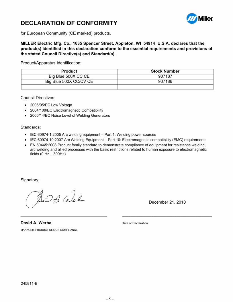
DECLARATION OF CONFORMITY
for European Community (CE marked) products.
MILLER Electric Mfg. Co., 1635 Spencer Street, Appleton, WI 54914 U.S.A. declares that the
product(s) identified in this declaration conform to the essential requirements and provisions of
the stated Council Directive(s) and Standard(s).
Product/Apparatus Identification:
Product Stock Number
Big Blue 500X CC CE 907187
Big Blue 500X CC/CV CE 907186
Council Directives:
• 2006/95/EC Low Voltage
• 2004/108/EC Electromagnetic Compatibility
• 2000/14/EC Noise Level of Welding Generators
Standards:
• IEC 609741:2005 Arc welding equipment – Part 1: Welding power sources
• IEC 6097410:2007 Arc Welding Equipment – Part 10: Electromagnetic compatibility (EMC) requirements
• EN 50445:2008 Product family standard to demonstrate compliance of equipment for resistance welding,arc welding and allied processes with the basic restrictions related to human exposure to electromagneticfields (0 Hz – 300Hz)
Signatory:
_____________________________________ ___________________________________________
David A. Werba Date of Declaration
MANAGER, PRODUCT DESIGN COMPLIANCE
245811B
December 21, 2010
OM-4421 Page 1
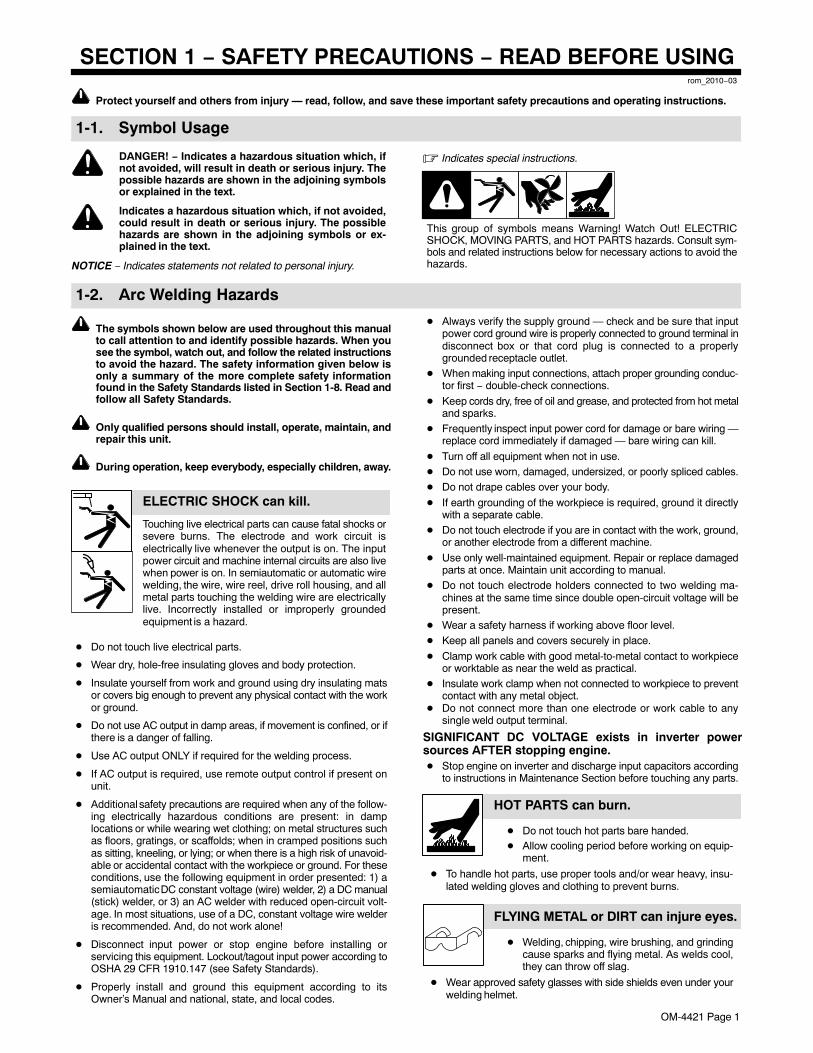
SECTION 1 − SAFETY PRECAUTIONS − READ BEFORE USINGrom_2010−03
Protect yourself and others from injury — read, follow, and save these important safety precautions and operating instructions.
1-1. Symbol Usage
DANGER! − Indicates a hazardous situation which, ifnot avoided, will result in death or serious injury. Thepossible hazards are shown in the adjoining symbolsor explained in the text.
Indicates a hazardous situation which, if not avoided,could result in death or serious injury. The possiblehazards are shown in the adjoining symbols or ex-plained in the text.
NOTICE − Indicates statements not related to personal injury.
� Indicates special instructions.
This group of symbols means Warning! Watch Out! ELECTRICSHOCK, MOVING PARTS, and HOT PARTS hazards. Consult sym-bols and related instructions below for necessary actions to avoid thehazards.
1-2. Arc Welding Hazards
The symbols shown below are used throughout this manualto call attention to and identify possible hazards. When yousee the symbol, watch out, and follow the related instructionsto avoid the hazard. The safety information given below isonly a summary of the more complete safety informationfound in the Safety Standards listed in Section 1-8. Read andfollow all Safety Standards.
Only qualified persons should install, operate, maintain, andrepair this unit.
During operation, keep everybody, especially children, away.
Touching live electrical parts can cause fatal shocks orsevere burns. The electrode and work circuit iselectrically live whenever the output is on. The inputpower circuit and machine internal circuits are also livewhen power is on. In semiautomatic or automatic wirewelding, the wire, wire reel, drive roll housing, and allmetal parts touching the welding wire are electricallylive. Incorrectly installed or improperly groundedequipment is a hazard.
ELECTRIC SHOCK can kill.
� Do not touch live electrical parts.
� Wear dry, hole-free insulating gloves and body protection.
� Insulate yourself from work and ground using dry insulating matsor covers big enough to prevent any physical contact with the workor ground.
� Do not use AC output in damp areas, if movement is confined, or ifthere is a danger of falling.
� Use AC output ONLY if required for the welding process.
� If AC output is required, use remote output control if present onunit.
� Additional safety precautions are required when any of the follow-ing electrically hazardous conditions are present: in damplocations or while wearing wet clothing; on metal structures suchas floors, gratings, or scaffolds; when in cramped positions suchas sitting, kneeling, or lying; or when there is a high risk of unavoid-able or accidental contact with the workpiece or ground. For theseconditions, use the following equipment in order presented: 1) asemiautomatic DC constant voltage (wire) welder, 2) a DC manual(stick) welder, or 3) an AC welder with reduced open-circuit volt-age. In most situations, use of a DC, constant voltage wire welderis recommended. And, do not work alone!
� Disconnect input power or stop engine before installing orservicing this equipment. Lockout/tagout input power according toOSHA 29 CFR 1910.147 (see Safety Standards).
� Properly install and ground this equipment according to itsOwner’s Manual and national, state, and local codes.
� Always verify the supply ground — check and be sure that inputpower cord ground wire is properly connected to ground terminal indisconnect box or that cord plug is connected to a properlygrounded receptacle outlet.
� When making input connections, attach proper grounding conduc-tor first − double-check connections.
� Keep cords dry, free of oil and grease, and protected from hot metaland sparks.
� Frequently inspect input power cord for damage or bare wiring —replace cord immediately if damaged — bare wiring can kill.
� Turn off all equipment when not in use.� Do not use worn, damaged, undersized, or poorly spliced cables.� Do not drape cables over your body.
� If earth grounding of the workpiece is required, ground it directlywith a separate cable.
� Do not touch electrode if you are in contact with the work, ground,or another electrode from a different machine.
� Use only well-maintained equipment. Repair or replace damagedparts at once. Maintain unit according to manual.
� Do not touch electrode holders connected to two welding ma-chines at the same time since double open-circuit voltage will bepresent.
� Wear a safety harness if working above floor level.� Keep all panels and covers securely in place.
� Clamp work cable with good metal-to-metal contact to workpieceor worktable as near the weld as practical.
� Insulate work clamp when not connected to workpiece to preventcontact with any metal object.
� Do not connect more than one electrode or work cable to anysingle weld output terminal.
SIGNIFICANT DC VOLTAGE exists in inverter powersources AFTER stopping engine.� Stop engine on inverter and discharge input capacitors according
to instructions in Maintenance Section before touching any parts.
HOT PARTS can burn.
� Do not touch hot parts bare handed.� Allow cooling period before working on equip-
ment.
� To handle hot parts, use proper tools and/or wear heavy, insu-lated welding gloves and clothing to prevent burns.
FLYING METAL or DIRT can injure eyes.
� Welding, chipping, wire brushing, and grindingcause sparks and flying metal. As welds cool,they can throw off slag.
� Wear approved safety glasses with side shields even under yourwelding helmet.
OM-4421 Page 2
Welding produces fumes and gases. Breathing thesefumes and gases can be hazardous to your health.
FUMES AND GASES can be hazardous.
� Keep your head out of the fumes. Do not breathe the fumes.� If inside, ventilate the area and/or use local forced ventilation at the
arc to remove welding fumes and gases.� If ventilation is poor, wear an approved air-supplied respirator.� Read and understand the Material Safety Data Sheets (MSDSs)
and the manufacturer’s instructions for metals, consumables,coatings, cleaners, and degreasers.
� Work in a confined space only if it is well ventilated, or whilewearing an air-supplied respirator. Always have a trained watch-person nearby. Welding fumes and gases can displace air andlower the oxygen level causing injury or death. Be sure the breath-ing air is safe.
� Do not weld in locations near degreasing, cleaning, or spraying op-erations. The heat and rays of the arc can react with vapors to formhighly toxic and irritating gases.
� Do not weld on coated metals, such as galvanized, lead, orcadmium plated steel, unless the coating is removed from the weldarea, the area is well ventilated, and while wearing an air-suppliedrespirator. The coatings and any metals containing these elementscan give off toxic fumes if welded.
BUILDUP OF GAS can injure or kill.
� Shut off shielding gas supply when not in use.� Always ventilate confined spaces or use ap-
proved air-supplied respirator.
Arc rays from the welding process produce intensevisible and invisible (ultraviolet and infrared) rays thatcan burn eyes and skin. Sparks fly off from the weld.
ARC RAYS can burn eyes and skin.
� Wear an approved welding helmet fitted with a proper shade of filterlenses to protect your face and eyes from arc rays and sparkswhen welding or watching (see ANSI Z49.1 and Z87.1 listed inSafety Standards).
� Wear approved safety glasses with side shields under yourhelmet.
� Use protective screens or barriers to protect others from flash,glare, and sparks; warn others not to watch the arc.
� Wear protective clothing made from durable, flame-resistant mate-rial (leather, heavy cotton, or wool) and foot protection.
Welding on closed containers, such as tanks, drums,or pipes, can cause them to blow up. Sparks can fly offfrom the welding arc. The flying sparks, hot workpiece,
and hot equipment can cause fires and burns. Accidental contact ofelectrode to metal objects can cause sparks, explosion, overheating,or fire. Check and be sure the area is safe before doing any welding.
WELDING can cause fire or explosion.
� Remove all flammables within 35 ft (10.7 m) of the welding arc. Ifthis is not possible, tightly cover them with approved covers.
� Do not weld where flying sparks can strike flammable material.
� Protect yourself and others from flying sparks and hot metal.
� Be alert that welding sparks and hot materials from welding caneasily go through small cracks and openings to adjacent areas.
� Watch for fire, and keep a fire extinguisher nearby.
� Be aware that welding on a ceiling, floor, bulkhead, or partition cancause fire on the hidden side.
� Do not weld on closed containers such as tanks, drums, or pipes,unless they are properly prepared according to AWS F4.1 (seeSafety Standards).
� Do not weld where the atmosphere may contain flammable dust,gas, or liquid vapors (such as gasoline).
� Connect work cable to the work as close to the welding area aspractical to prevent welding current from traveling long, possiblyunknown paths and causing electric shock, sparks, and fire haz-ards.
� Do not use welder to thaw frozen pipes.
� Remove stick electrode from holder or cut off welding wire atcontact tip when not in use.
� Wear oil-free protective garments such as leather gloves, heavyshirt, cuffless trousers, high shoes, and a cap.
� Remove any combustibles, such as a butane lighter or matches,from your person before doing any welding.
� After completion of work, inspect area to ensure it is free of sparks,glowing embers, and flames.
� Use only correct fuses or circuit breakers. Do not oversize or by-pass them.
� Follow requirements in OSHA 1910.252 (a) (2) (iv) and NFPA 51Bfor hot work and have a fire watcher and extinguisher nearby.
NOISE can damage hearing.
Noise from some processes or equipment can dam-age hearing.
� Wear approved ear protection if noise level ishigh.
ELECTRIC AND MAGNETIC FIELDS (EMF)can affect Implanted Medical Devices.
� Wearers of Pacemakers and other ImplantedMedical Devices should keep away.
� Implanted Medical Device wearers should consult their doctorand the device manufacturer before going near arc welding, spotwelding, gouging, plasma arc cutting, or induction heatingoperations.
Shielding gas cylinders contain gas under high pres-sure. If damaged, a cylinder can explode. Since gascylinders are normally part of the welding process, besure to treat them carefully.
CYLINDERS can explode if damaged.
� Protect compressed gas cylinders from excessive heat, mechani-cal shocks, physical damage, slag, open flames, sparks, and arcs.
� Install cylinders in an upright position by securing to a stationarysupport or cylinder rack to prevent falling or tipping.
� Keep cylinders away from any welding or other electrical circuits.
� Never drape a welding torch over a gas cylinder.
� Never allow a welding electrode to touch any cylinder.
� Never weld on a pressurized cylinder — explosion will result.
� Use only correct shielding gas cylinders, regulators, hoses, and fit-tings designed for the specific application; maintain them andassociated parts in good condition.
� Turn face away from valve outlet when opening cylinder valve.
� Keep protective cap in place over valve except when cylinder is inuse or connected for use.
� Use the right equipment, correct procedures, and sufficient num-ber of persons to lift and move cylinders.
� Read and follow instructions on compressed gas cylinders,associated equipment, and Compressed Gas Association (CGA)publication P-1 listed in Safety Standards.
OM-4421 Page 3
1-3. Engine Hazards
BATTERY EXPLOSION can injure.
� Always wear a face shield, rubber gloves, andprotective clothing when working on a battery.
� Stop engine before disconnecting or connect-ing battery cables, battery charging cables (ifapplicable), or servicing battery.
� Do not allow tools to cause sparks when working on a battery.
� Do not use welder to charge batteries or jump start vehicles un-less the unit has a battery charging feature designed for this pur-pose.
� Observe correct polarity (+ and −) on batteries.
� Disconnect negative (−) cable first and connect it last.
� Keep sparks, flames, cigarettes, and other ignition sourcesaway from batteries. Batteries produce explosive gases duringnormal operation and when being charged.
� Follow battery manufacturer’s instructions when working on ornear a battery.
BATTERY CHARGING OUTPUT can injure.(Battery charging feature not present on all models.)
� Have only qualified persons do battery charging work.
� Charge lead-acid batteries only. Do not use battery charger tosupply power to an extra-low-voltage electrical system or tocharge dry cell batteries.
� Do not charge a frozen battery.
� Do not use damaged charging cables.
� Do not charge a battery that has loose terminals or one showingdamage such as a cracked case or cover.
� Before charging battery, select correct charger voltage to matchbattery voltage.
� Set battery charging controls to the Off position before connect-ing to battery. Do not allow battery charging clips to touch eachother.
� Keep charging cables away from vehicle hood, door, or movingparts.
FUEL can cause fire or explosion.
� Stop engine and let it cool off before checking oradding fuel.
� Do not add fuel while smoking or if unit is nearany sparks or open flames.
� Do not overfill tank — allow room for fuel to expand.
� Do not spill fuel. If fuel is spilled, clean up before starting engine.
� Dispose of rags in a fireproof container.
� Always keep nozzle in contact with tank when fueling.
MOVING PARTS can injure.
� Keep away from moving parts such as fans,belts, and rotors.
� Keep all doors, panels, covers, and guardsclosed and securely in place.
� Stop engine before installing or connecting unit.� Have only qualified persons remove doors, panels, covers, or
guards for maintenance and troubleshooting as necessary.� To prevent accidental starting during servicing, disconnect
negative (−) battery cable from battery.� Keep hands, hair, loose clothing, and tools away from moving
parts.� Reinstall doors, panels, covers, or guards when servicing is
finished and before starting engine.� Before working on generator, remove spark plugs or injectors to
keep engine from kicking back or starting.� Block flywheel so that it will not turn while working on generator
components.
EXHAUST SPARKS can cause fire.
� Do not let engine exhaust sparks cause fire.� Use approved engine exhaust spark arrestor in
required areas — see applicable codes.
HOT PARTS can burn.
� Do not touch hot parts bare handed.� Allow cooling period before working on equip-
ment.� To handle hot parts, use proper tools and/or
wear heavy, insulated welding gloves andclothing to prevent burns.
STEAM AND HOT COOLANT can burn.
� If possible, check coolant level when engine iscold to avoid scalding.
� Always check coolant level at overflow tank, ifpresent on unit, instead of radiator (unless toldotherwise in maintenance section or enginemanual).
� If the engine is warm, checking is needed, and there is no over-flow tank, follow the next two statements.
� Wear safety glasses and gloves and put a rag over radiator cap.
� Turn cap slightly and let pressure escape slowly beforecompletely removing cap.
Using a generator indoors CAN KILLYOU IN MINUTES.
� Generator exhaust contains carbon monoxide.This is a poison you cannot see or smell.
� NEVER use inside a home or garage, EVEN IFdoors and windows are open.
� Only use OUTSIDE and far away from windows, doors, andvents.
BATTERY ACID can BURN SKIN and EYES.
� Do not tip battery.� Replace damaged battery.� Flush eyes and skin immediately with water.
ENGINE HEAT can cause fire.
� Do not locate unit on, over, or near combustiblesurfaces or flammables.
� Keep exhaust and exhaust pipes way fromflammables.
OM-4421 Page 4
1-4. Hydraulic Hazards
HYDRAULIC EQUIPMENT can injureor kill.� Incorrect installation or operation of this unit
could result in equipment failure and personalinjury. Only qualified persons should install, op-erate, and service this unit according to itsOwner’s Manual, industry standards, and na-tional, state, and local codes.
� Do not exceed the rated output or capacity of the hydraulic pumpor any equipment in the hydraulic system. Design hydraulic sys-tem so failure of any hydraulic component will not put people orproperty at risk.
� Before working on hydraulic system, turn off and lockout/tagoutunit, release pressure, and be sure hydraulic pressure cannot beaccidentally applied.
� Do not work on hydraulic system with unit running unless you area qualified person and following the manufacturer’s instructions.
� Do not modify or alter hydraulic pump or manufacturer-suppliedequipment. Do not disconnect, disable, or override any safetyequipment in the hydraulic system.
� Use only components/accessories approved by the manufac-turer.
� Keep away from potential pinch points or crush points created byequipment connected to the hydraulic system.
� Do not work under or around any equipment that is supportedonly by hydraulic pressure. Properly support equipment bymechanical means.
HYDRAULIC FLUID can injure or kill.
� Before working on hydraulic system, turn off andlockout/tagout unit, release pressure, and be surehydraulic pressure cannot be accidentally applied.
� Relieve pressure before disconnecting or con-necting hydraulic lines.
� Check hydraulic system components and all con-nections and hoses for damage, leaks, and wearbefore operating unit.
� Wear protective equipment such as safetyglasses, leather gloves, heavy shirt and trousers,high shoes, and a cap when working on hydraulicsystem.
� Use a piece of paper or cardboard to search for leaks−−never usebare hands. Do not use equipment if leaks are found.
� HYDRAULIC FLUID is FLAMMABLE−−do not work on hydraulicsnear sparks or flames; do not smoke near hydraulic fluid.
� Reinstall doors, panels, covers, or guards when servicing isfinished and before starting unit.
� If ANY fluid is injected into the skin, it must be surgically removedwithin a few hours by a doctor familiar with this type of injury or gan-grene may result.
MOVING PARTS can injure.
� Keep away from moving parts such as fans,belts and rotors.
� Keep all doors, panels, covers, and guardsclosed and securely in place.
� Keep hands, hair, loose clothing, and tools away from movingparts.
� Before working on hydraulic system, turn off and lockout/tagoutunit, release pressure, and be sure hydraulic pressure cannot beaccidentally applied.
� Have only qualified people remove guards or covers for maint-enance and troubleshooting as necessary.
� Reinstall doors, panels, covers, or guards when servicing isfinished and before starting engine.
HOT PARTS AND FLUID can burn.
� Do not touch hot parts bare handed or allow hotfluid to contact skin.
� Allow cooling period before working on equip-ment.
� To handle hot parts, use proper tools and/or wear heavy, insu-lated welding gloves and clothing to prevent burns.
READ INSTRUCTIONS.
� Read and follow all labels and the Owner’sManual carefully before installing, operating, orservicing unit. Read the safety information atthe beginning of the manual and in eachsection.
� Use only genuine replacement parts from the manufacturer.
� Perform maintenance and service according to the Owner’sManuals, industry standards, and national, state, and localcodes.
1-5. Compressed Air Hazards
COMPRESSED AIR EQUIPMENT caninjure or kill.
� Incorrect installation or operation of this unitcould result in equipment failure and personalinjury. Only qualified persons should install, op-erate, and service this unit according to itsOwner’s Manual, industry standards, and na-tional, state, and local codes.
� Do not exceed the rated output or capacity of the compressor orany equipment in the compressed air system. Design compressedair system so failure of any component will not put people or prop-erty at risk.
� Before working on compressed air system, turn off and lockout/tagout unit, release pressure, and be sure air pressure cannot beaccidentally applied.
� Do not work on compressed air system with unit running unlessyou are a qualified person and following the manufacturer’s in-structions.
� Do not modify or alter compressor or manufacturer-suppliedequipment. Do not disconnect, disable, or override any safetyequipment in the compressed air system.
� Use only components and accessories approved by the manufac-turer.
� Keep away from potential pinch points or crush points created byequipment connected to the compressed air system.
� Do not work under or around any equipment that is supported onlyby air pressure. Properly support equipment by mechanicalmeans.
OM-4421 Page 5
HOT METAL from air arc cutting andgouging can cause fire or explosion.
� Do not cut or gouge near flammables.� Watch for fire; keep extinguisher nearby.
COMPRESSED AIR can injure or kill.
� Before working on compressed air system,turn off and lockout/tagout unit, release pres-sure, and be sure air pressure cannot be acci-dentally applied.
� Relieve pressure before disconnecting or con-necting air lines.
� Check compressed air system componentsand all connections and hoses for damage,leaks, and wear before operating unit.
� Do not direct air stream toward self or others.
� Wear protective equipment such as safety glasses, hearing pro-tection, leather gloves, heavy shirt and trousers, high shoes, anda cap when working on compressed air system.
� Use soapy water or an ultrasonic detector to search forleaks−−never use bare hands. Do not use equipment if leaks arefound.
� Reinstall doors, panels, covers, or guards when servicing isfinished and before starting unit.
� If ANY air is injected into the skin or body seek medical help im-mediately.
BREATHING COMPRESSED AIR can in-jure or kill.
� Do not use compressed air for breathing.� Use only for cutting, gouging, and tools.
TRAPPED AIR PRESSURE AND WHIPPINGHOSES can injure.
� Release air pressure from tools and system be-fore servicing, adding or changing attach-ments, or opening compressor oil drain or oil fillcap.
MOVING PARTS can injure.
� Keep away from moving parts such as fans,belts and rotors.
� Keep all doors, panels, covers, and guardsclosed and securely in place.
� Keep hands, hair, loose clothing, and tools away from movingparts.
� Before working on compressed air system, turn off and lockout/tagout unit, release pressure, and be sure air pressure cannot beaccidentally applied.
� Have only qualified people remove guards or covers for maint-enance and troubleshooting as necessary.
� Reinstall doors, panels, covers, or guards when servicing isfinished and before starting engine.
HOT PARTS can burn.
� Do not touch hot compressor or air systemparts.
� Allow cooling period before working on equip-ment.
� To handle hot parts, use proper tools and/or wear heavy, insu-lated welding gloves and clothing to prevent burns.
READ INSTRUCTIONS.
� Read and follow all labels and the Owner’sManual carefully before installing, operating, orservicing unit. Read the safety information atthe beginning of the manual and in eachsection.
� Use only genuine replacement parts from the manufacturer.
� Perform maintenance and service according to the Owner’sManuals, industry standards, and national, state, and localcodes.
1-6. Additional Symbols For Installation, Operation, And Maintenance
FIRE OR EXPLOSION hazard.
� Do not install or place unit on, over, or nearcombustible surfaces.
� Do not install unit near flammables.
� Do not overload building wiring − be sure power supply system isproperly sized, rated, and protected to handle this unit.
FALLING EQUIPMENT can injure.
� Use lifting eye to lift unit and properly installedaccessories only, NOT gas cylinders. Do notexceed maximum lift eye weight rating (seeSpecifications).
� Use equipment of adequate capacity to lift andsupport unit.
� If using lift forks to move unit, be sure forks are long enough toextend beyond opposite side of unit.
� Keep equipment (cables and cords) away from moving vehicleswhen working from an aerial location.
� Follow the guidelines in the Applications Manual for the RevisedNIOSH Lifting Equation (Publication No. 94−110) when manu-ally lifting heavy parts or equipment.
OVERHEATING can damage motors.
� Turn off or unplug equipment before starting orstopping engine.
� Do not let low voltage and frequency caused bylow engine speed damage electric motors.
� Do not connect 50 or 60 Hertz motors to the 100 Hertz receptaclewhere applicable.
FLYING SPARKS can injure.
� Wear a face shield to protect eyes and face.� Shape tungsten electrode only on grinder with
proper guards in a safe location wearing properface, hand, and body protection.
� Sparks can cause fires — keep flammables away.
MOVING PARTS can injure.
� Keep away from moving parts.� Keep away from pinch points such as drive
rolls.
OM-4421 Page 6
WELDING WIRE can injure.
� Do not press gun trigger until instructed to doso.
� Do not point gun toward any part of the body,other people, or any metal when threadingwelding wire.
OVERUSE can cause OVERHEATING.
� Allow cooling period; follow rated duty cycle.� Reduce current or reduce duty cycle before
starting to weld again.� Do not block or filter airflow to unit.
STATIC (ESD) can damage PC boards.
� Put on grounded wrist strap BEFORE handlingboards or parts.
� Use proper static-proof bags and boxes tostore, move, or ship PC boards.
TILTING OF TRAILER can injure.
� Use tongue jack or blocks to support weight.� Properly install welding generator onto trailer
according to instructions supplied with trailer.
READ INSTRUCTIONS.
� Read and follow all labels and the Owner’sManual carefully before installing, operating, orservicing unit. Read the safety information atthe beginning of the manual and in eachsection.
� Use only genuine replacement parts from the manufacturer.
� Perform maintenance and service according to the Owner’sManuals, industry standards, and national, state, and localcodes.
H.F. RADIATION can cause interference.
� High-frequency (H.F.) can interfere with radionavigation, safety services, computers, andcommunications equipment.
� Have only qualified persons familiar withelectronic equipment perform this installation.
� The user is responsible for having a qualified electricianpromptly correct any interference problem resulting from theinstallation.
� If notified by the FCC about interference, stop using theequipment at once.
� Have the installation regularly checked and maintained.
� Keep high-frequency source doors and panels tightly shut, keepspark gaps at correct setting, and use grounding and shielding tominimize the possibility of interference.
ARC WELDING can cause interference.
� Electromagnetic energy can interfere withsensitive electronic equipment such as micro-processors, computers, and computer-drivenequipment such as robots.
� Be sure all equipment in the welding area iselectromagnetically compatible.
� To reduce possible interference, keep weld cables as short aspossible, close together, and down low, such as on the floor.
� Locate welding operation 100 meters from any sensitive elec-tronic equipment.
� Be sure this welding machine is installed and groundedaccording to this manual.
� If interference still occurs, the user must take extra measuressuch as moving the welding machine, using shielded cables,using line filters, or shielding the work area.
1-7. California Proposition 65 Warnings
Welding or cutting equipment produces fumes or gaseswhich contain chemicals known to the State of California tocause birth defects and, in some cases, cancer. (CaliforniaHealth & Safety Code Section 25249.5 et seq.)
Battery posts, terminals and related accessories contain leadand lead compounds, chemicals known to the State ofCalifornia to cause cancer and birth defects or otherreproductive harm. Wash hands after handling.
This product contains chemicals, including lead, known tothe state of California to cause cancer, birth defects, or otherreproductive harm. Wash hands after use.
For Gasoline Engines:
Engine exhaust contains chemicals known to the State ofCalifornia to cause cancer, birth defects, or other reproduc-tive harm.
For Diesel Engines:
Diesel engine exhaust and some of its constituents areknown to the State of California to cause cancer, birthdefects, and other reproductive harm.
OM-4421 Page 7
1-8. Principal Safety StandardsSafety in Welding, Cutting, and Allied Processes, ANSI Standard Z49.1,from Global Engineering Documents (phone: 1-877-413-5184, website:www.global.ihs.com).Safe Practices for the Preparation of Containers and Piping for Weldingand Cutting, American Welding Society Standard AWS F4.1, from Glob-al Engineering Documents (phone: 1-877-413-5184, website:www.global.ihs.com).National Electrical Code, NFPA Standard 70, from National Fire Protec-tion Association, Quincy, MA 02269 (phone: 1-800-344-3555, website:www.nfpa.org and www. sparky.org).Safe Handling of Compressed Gases in Cylinders, CGA Pamphlet P-1,from Compressed Gas Association, 4221 Walney Road, 5th Floor,Chantilly, VA 20151 (phone: 703-788-2700, website:www.cganet.com).Safety in Welding, Cutting, and Allied Processes, CSA StandardW117.2, from Canadian Standards Association, Standards Sales, 5060Spectrum Way, Suite 100, Ontario, Canada L4W 5NS (phone:800-463-6727, website: www.csa-international.org).Battery Chargers, CSA Standard C22.2 NO 107.2−01, from CanadianStandards Association, Standards Sales, 5060 Spectrum Way, Suite100, Ontario, Canada L4W 5NS (phone: 800-463-6727, website:www.csa-international.org).Safe Practice For Occupational And Educational Eye And Face Protec-tion, ANSI Standard Z87.1, from American National Standards Institute,
25 West 43rd Street, New York, NY 10036 (phone: 212-642-4900, web-site: www.ansi.org).Standard for Fire Prevention During Welding, Cutting, and Other HotWork, NFPA Standard 51B, from National Fire Protection Association,Quincy, MA 02269 (phone: 1-800-344-3555, website: www.nfpa.org.For Standards about hydraulic systems, contact the National FluidPower Association, Publications Department, 3333 North MayfairRoad, Suite 211, Milwaukee, WI 53222-3219 (phone: (414) 778-3344,website: www.nfpa.com).
OSHA, Occupational Safety and Health Standards for General Indus-try, Title 29, Code of Federal Regulations (CFR), Part 1910, Subpart Q,and Part 1926, Subpart J, from U.S. Government Printing Office, Super-intendent of Documents, P.O. Box 371954, Pittsburgh, PA 15250-7954(phone: 1-866-512-1800) (there are 10 OSHA Regional Offices—phone for Region 5, Chicago, is 312-353-2220, website:www.osha.gov).U.S. Consumer Product Safety Commission (CPSC), 4330 East WestHighway, Bethesda, MD 20814 (phone: 301-504-7923, website:www.cpsc.gov).Applications Manual for the Revised NIOSH Lifting Equation, The Na-tional Institute for Occupational Safety and Health (NIOSH), 1600Clifton Rd, Atlanta, GA 30333 (phone: 1-800-232-4636, website:www.cdc.gov/NIOSH).
1-9. EMF InformationElectric current flowing through any conductor causes localized electricand magnetic fields (EMF). Welding current creates an EMF fieldaround the welding circuit and welding equipment. EMF fields may inter-fere with some medical implants, e.g. pacemakers. Protectivemeasures for persons wearing medical implants have to be taken. Forexample, access restrictions for passers−by or individual risk assess-ment for welders. All welders should use the following procedures inorder to minimize exposure to EMF fields from the welding circuit:
1. Keep cables close together by twisting or taping them, or using acable cover.
2. Do not place your body between welding cables. Arrange cablesto one side and away from the operator.
3. Do not coil or drape cables around your body.
4. Keep head and trunk as far away from the equipment in thewelding circuit as possible.
5. Connect work clamp to workpiece as close to the weld aspossible.
6. Do not work next to, sit or lean on the welding power source.
7. Do not weld whilst carrying the welding power source or wirefeeder.
About Implanted Medical Devices:Implanted Medical Device wearers should consult their doctor and thedevice manufacturer before performing or going near arc welding, spotwelding, gouging, plasma arc cutting, or induction heating operations.If cleared by your doctor, then following the above procedures is recom-mended.
OM-4421 Page 8
SECTION 2 − CONSIGNES DE SÉCURITÉ − LIRE AVANTUTILISATION
fre_rom_2010−03
Pour écarter les risques de blessure pour vous−même et pour autrui — lire, appliquer et ranger en lieu sûr ces consignes relativesaux précautions de sécurité et au mode opératoire.
2-1. Signification des symboles
DANGER! − Indique une situation dangereuse qui si onl’évite pas peut donner la mort ou des blessures graves.Les dangers possibles sont montrés par les symbolesjoints ou sont expliqués dans le texte.
Indique une situation dangereuse qui si on l’évite paspeut donner la mort ou des blessures graves. Les dan-gers possibles sont montrés par les symboles joints ousont expliqués dans le texte.
NOTE − Indique des déclarations pas en relation avec des blessurespersonnelles.
� Indique des instructions spécifiques.
Ce groupe de symboles veut dire Avertissement! Attention! DANGERDE CHOC ELECTRIQUE, PIECES EN MOUVEMENT, et PIECESCHAUDES. Consulter les symboles et les instructions ci-dessous yafférant pour les actions nécessaires afin d’éviter le danger.
2-2. Dangers relatifs au soudage à l’arc
Les symboles présentés ci-après sont utilisés tout au long duprésent manuel pour attirer votre attention et identifier les ris-ques de danger. Lorsque vous voyez un symbole, soyezvigilant et suivez les directives mentionnées afin d’éviter toutdanger. Les consignes de sécurité présentées ci-après nefont que résumer l’information contenue dans les normes desécurité énumérées à la section 2-8. Veuillez lire et respectertoutes ces normes de sécurité.
L’installation, l’utilisation, l’entretien et les réparations nedoivent être confiés qu’à des personnes qualifiées.
Au cours de l’utilisation, tenir toute personne à l’écart et plusparticulièrement les enfants.
Un simple contact avec des pièces électriques peutprovoquer une électrocution ou des blessures gra-ves. L’électrode et le circuit de soudage sont soustension dès que l’appareil est sur ON. Le circuitd’entrée et les circuits internes de l’appareil sontégalement sous tension à ce moment-là. En soudagesemi-automatique ou automatique, le fil, le dévidoir, lelogement des galets d’entraînement et les piècesmétalliques en contact avec le fil de soudage sontsous tension. Des matériels mal installés ou mal misà la terre présentent un danger.
UN CHOC ÉLECTRIQUE peut tuer.
� Ne jamais toucher les pièces électriques sous tension.
� Porter des gants et des vêtements de protection secs ne compor-tant pas de trous.
� S’isoler de la pièce et de la terre au moyen de tapis ou d’autresmoyens isolants suffisamment grands pour empêcher le contactphysique éventuel avec la pièce ou la terre.
� Ne pas se servir de source électrique à courant électrique dans leszones humides, dans les endroits confinés ou là où on risque detomber.
� Se servir d’une source électrique à courant électrique UNIQUE-MENT si le procédé de soudage le demande.
� Si l’utilisation d’une source électrique à courant électrique s’avèrenécessaire, se servir de la fonction de télécommande si l’appareilen est équipé.
� Des précautions de sécurité supplémentaires sont requises dansdes environnements à risque comme: les endroits humides oulorsque l’on porte des vêtements mouillés; sur des structures mé-talliques au sol, grillages et échafaudages; dans des positionsassises, à genoux et allongées; ou quand il y a un risque importantde contact accidentel avec la pièce ou le sol. Dans ces cas utiliserles appareils suivants dans l’ordre de préférence: 1) un poste àsouder DC semi−automatique de type CV (MIG/MAG), 2) un poste
à souder manuel (électrode enrobée) DC, 3) un poste à soudermanuel AC avec tension à vide réduite. Dans la plupart des cas, unposte courant continu de type CV est recommandé. Et, ne pas tra-vailler seul!
� Couper l’alimentation ou arrêter le moteur avant de procéder àl’installation, à la réparation ou à l’entretien de l’appareil.Déverrouiller l’alimentation selon la norme OSHA 29 CFR1910.147 (voir normes de sécurité).
� Installer et mettre à la terre correctement cet appareil conformé-ment à son manuel d’utilisation et aux codes nationaux,provinciaux et municipaux.
� Toujours vérifier la terre du cordon d’alimentation − Vérifier ets’assurer que le fil de terre du cordon d’alimentation est bienraccordé à la borne de terre du sectionneur ou que la fiche ducordon est raccordée à une prise correctement mise à la terre.
� En effectuant les raccordements d’entrée fixer d’abord le conduc-teur de mise à la terre approprié et contre-vérifier les connexions.
� Les câbles doivent être exempts d’humidité, d’huile et de graisse;protégez−les contre les étincelles et les pièces métalliques chau-des.
� Vérifier fréquemment le cordon d’alimentation pour voir s’il n’estpas endommagé ou dénudé − remplacer le cordon immédiatements’il est endommagé − un câble dénudé peut provoquer une électro-cution.
� Mettre l’appareil hors tension quand on ne l’utilise pas.� Ne pas utiliser des câbles usés, endommagés, de grosseur insuffi-
sante ou mal épissés.� Ne pas enrouler les câbles autour du corps.� Si la pièce soudée doit être mise à la terre, le faire directement
avec un câble distinct − ne pas utiliser le connecteur de pièce ou lecâble de retour.
� Ne pas toucher l’électrode quand on est en contact avec la pièce,la terre ou une électrode provenant d’une autre machine.
� Ne pas toucher des porte électrodes connectés à deux machinesen même temps à cause de la présence d’une tension à vide dou-blée.
� N’utiliser qu’un matériel en bon état. Réparer ou remplacersur-le-champ les pièces endommagées. Entretenir l’appareilconformément à ce manuel.
� Porter un harnais de sécurité quand on travaille en hauteur.� Maintenir solidement en place tous les panneaux et capots.� Fixer le câble de retour de façon à obtenir un bon contact métal-
métal avec la pièce à souder ou la table de travail, le plus près pos-sible de la soudure.
� Isoler la pince de masse quand pas mis à la pièce pour éviter lecontact avec tout objet métallique.
Il reste une TENSION DC NON NÉGLIGEABLE dans lessources de soudage onduleur UNE FOIS le moteur coupé.� Couper l’alimentation du poste et décharger les condensateurs
d’entrée comme indiqué dans la Section Maintenance avant detoucher des composants.
OM-4421 Page 9
LES PIÈCES CHAUDES peuventprovoquer des brûlures.
� Ne pas toucher à mains nues les parties chau-des.
� Prévoir une période de refroidissement avantde travailler à l’équipement.
� Ne pas toucher aux pièces chaudes, utiliser les outils recomman-dés et porter des gants de soudage et des vêtements épais pouréviter les brûlures.
DES PIECES DE METAL ou DESSALETES peuvent provoquerdes blessures dans les yeux.
� Le soudage, l’écaillement, le passage de la pièce à la brosse enfil de fer, et le meulage génèrent des étincelles et des particulesmétalliques volantes. Pendant la période de refroidissement dessoudures, elles risquent de projeter du laitier.
� Porter des lunettes de sécurité avec écrans latéraux ou un écranfacial.
Le soudage génère des fumées et des gaz. Leurinhalation peut être dangereux pour votre santé.
LES FUMÉES ET LES GAZ peu-vent être dangereux.
� Eloigner votre tête des fumées. Ne pas respirer les fumées.
� À l’intérieur, ventiler la zone et/ou utiliser une ventilation forcée auniveau de l’arc pour l’évacuation des fumées et des gaz de soudage.
� Si la ventilation est médiocre, porter un respirateur anti-vapeursapprouvé.
� Lire et comprendre les spécifications de sécurité des matériaux(MSDS) et les instructions du fabricant concernant les métaux, lesconsommables, les revêtements, les nettoyants et les dégraisseurs.
� Travailler dans un espace fermé seulement s’il est bien ventilé ouen portant un respirateur à alimentation d’air. Demander toujours àun surveillant dûment formé de se tenir à proximité. Des fumées etdes gaz de soudage peuvent déplacer l’air et abaisser le niveaud’oxygène provoquant des blessures ou des accidents mortels.S’assurer que l’air de respiration ne présente aucun danger.
� Ne pas souder dans des endroits situés à proximité d’opérationsde dégraissage, de nettoyage ou de pulvérisation. La chaleur etles rayons de l’arc peuvent réagir en présence de vapeurs et for-mer des gaz hautement toxiques et irritants.
� Ne pas souder des métaux munis d’un revêtement, tels que l’aciergalvanisé, plaqué en plomb ou au cadmium à moins que le revête-ment n’ait été enlevé dans la zone de soudure, que l’endroit soitbien ventilé, et en portant un respirateur à alimentation d’air. Lesrevêtements et tous les métaux renfermant ces éléments peuventdégager des fumées toxiques en cas de soudage.
LES ACCUMULATIONS DE GAZrisquent de provoquer des blessuresou même la mort.
� Fermer l’alimentation du gaz protecteur en casde non utilisation.
� Veiller toujours à bien aérer les espaces confinés ou se servird’un respirateur d’adduction d’air homologué.
LES RAYONS DE L’ARC peuventprovoquer des brûlures dans lesyeux et sur la peau.Le rayonnement de l’arc du procédé de soudagegénère des rayons visibles et invisibles intenses
(ultraviolets et infrarouges) susceptibles de provoquer des brûluresdans les yeux et sur la peau. Des étincelles sont projetées pendant lesoudage.
� Porter un casque de soudage approuvé muni de verres filtrantsapproprié pour protéger visage et yeux pour protéger votre visageet vos yeux pendant le soudage ou pour regarder (voir ANSI Z49.1et Z87.1 énuméré dans les normes de sécurité).
� Porter des lunettes de sécurité avec écrans latéraux même sousvotre casque.
� Avoir recours à des écrans protecteurs ou à des rideaux pourprotéger les autres contre les rayonnements les éblouissementset les étincelles ; prévenir toute personne sur les lieux de ne pasregarder l’arc.
� Porter des vêtements confectionnés avec des matières résistan-tes et ignifuges (cuir, coton lourd ou laine) et des bottes deprotection.
LE SOUDAGE peut provoquer unincendie ou une explosion.Le soudage effectué sur des conteneurs fermés telsque des réservoirs, tambours ou des conduites peutprovoquer leur éclatement. Des étincelles peuvent
être projetées de l’arc de soudure. La projection d’étincelles, despièces chaudes et des équipements chauds peut provoquer desincendies et des brûlures. Le contact accidentel de l’électrode avecdes objets métalliques peut provoquer des étincelles, une explosion,un surchauffement ou un incendie. Avant de commencer le soudage,vérifier et s’assurer que l’endroit ne présente pas de danger.
� Déplacer toutes les substances inflammables à une distance de10,7 m de l’arc de soudage. En cas d’impossibilité les recouvrirsoigneusement avec des protections homologués.
� Ne pas souder dans un endroit là où des étincelles peuvent tombersur des substances inflammables.
� Se protéger et d’autres personnes de la projection d’étincelles etde métal chaud.
� Des étincelles et des matériaux chauds du soudage peuventfacilement passer dans d’autres zones en traversant de petitesfissures et des ouvertures.
� Surveiller tout déclenchement d’incendie et tenir un extincteur àproximité.
� Le soudage effectué sur un plafond, plancher, paroi ou séparationpeut déclencher un incendie de l’autre côté.
� Ne pas effectuer le soudage sur des conteneurs fermés tels quedes réservoirs, tambours, ou conduites, à moins qu’ils n’aient étépréparés correctement conformément à AWS F4.1 (voir les nor-mes de sécurité).
� Ne soudez pas si l’air ambiant est chargé de particules, gaz, ou va-peurs inflammables (vapeur d’essence, par exemple).
� Brancher le câble de masse sur la pièce le plus près possible de lazone de soudage pour éviter le transport du courant sur unelongue distance par des chemins inconnus éventuels en provo-quant des risques d’électrocution, d’étincelles et d’incendie.
� Ne pas utiliser le poste de soudage pour dégeler des conduites ge-lées.
� En cas de non utilisation, enlever la baguette d’électrode du porte-électrode ou couper le fil à la pointe de contact.
� Porter des vêtements de protection dépourvus d’huile tels que desgants en cuir, une chemise en matériau lourd, des pantalons sansrevers, des chaussures hautes et un couvre chef.
� Avant de souder, retirer toute substance combustible de vos po-ches telles qu’un allumeur au butane ou des allumettes.
� Une fois le travail achevé, assurez−vous qu’il ne reste aucune tra-ce d’étincelles incandescentes ni de flammes.
� Utiliser exclusivement des fusibles ou coupe−circuits appropriés.Ne pas augmenter leur puissance; ne pas les ponter.
� Suivre les recommandations dans OSHA 1910.252(a)(2)(iv) etNFPA 51B pour les travaux à chaud et avoir de la surveillance et unextincteur à proximité.
LE BRUIT peut affecter l’ouïe.
Le bruit des processus et des équipements peutaffecter l’ouïe.
� Porter des protections approuvés pour lesoreilles si le niveau sonore est trop élevé.
OM-4421 Page 10
Les CHAMPS ÉLECTROMAGNÉTIQUES (CEM)peuvent affecter les implants médicaux.
� Les porteurs de stimulateurs cardiaques etautres implants médicaux doivent rester àdistance.
� Les porteurs d’implants médicaux doivent consulter leurmédecin et le fabricant du dispositif avant de s’approcher de lazone où se déroule du soudage à l’arc, du soudage par points, dugougeage, de la découpe plasma ou une opération de chauffagepar induction.
Si des BOUTEILLES sont endomma-gées, elles pourront exploser.
Des bouteilles de gaz protecteur contiennent du gazsous haute pression. Si une bouteille est endomma-
gée, elle peut exploser. Du fait que les bouteilles de gaz fontnormalement partie du procédé de soudage, les manipuler avecprécaution.
� Protéger les bouteilles de gaz comprimé d’une chaleur excessive,des chocs mécaniques, des dommages physiques, du laitier, desflammes ouvertes, des étincelles et des arcs.
� Placer les bouteilles debout en les fixant dans un support station-naire ou dans un porte-bouteilles pour les empêcher de tomber oude se renverser.
� Tenir les bouteilles éloignées des circuits de soudage ou autrescircuits électriques.
� Ne jamais placer une torche de soudage sur une bouteille à gaz.
� Une électrode de soudage ne doit jamais entrer en contact avecune bouteille.
� Ne jamais souder une bouteille pressurisée − risque d’explosion.
� Utiliser seulement des bouteilles de gaz protecteur, régulateurs,tuyaux et raccords convenables pour cette application spécifique;les maintenir ainsi que les éléments associés en bon état.
� Ne pas tenir la tête en face de la sortie en ouvrant la soupape de labouteille.
� Maintenir le chapeau de protection sur la soupape, sauf en casd’utilisation ou de branchement de la bouteille.
� Utiliser les équipements corrects, les bonnes procédures et suffi-samment de personnes pour soulever et déplacer les bouteilles.
� Lire et suivre les instructions sur les bouteilles de gaz comprimé,l’équipement connexe et le dépliant P-1 de la CGA (CompressedGas Association) mentionné dans les principales normes de sécu-rité.
2-3. Dangers existant en relation avec le moteur
L’EXPLOSION DE LA BATTERIEpeut provoquer des blessures.
� Toujours porter une protection faciale, desgants en caoutchouc et vêtements de protec-tion lors d’une intervention sur la batterie.
� Arrêter le moteur avant de débrancher ou de brancher des câblesde batterie, des câbles de chargeur de batterie (le cas échéant) oude batterie d’entretien.
� Eviter de provoquer des étincelles avec les outils en travaillant surla batterie.
� Ne pas utiliser l’appareil de soudage pour charger des batteries oufaire démarrer des véhicules à l’aide de câbles de démarrage, saufsi l’appareil dispose d’une fonctionnalité de charge de batteriedestinée à cet usage.
� Observer la polarité correcte (+ et −) sur les batteries.
� Débrancher le câble négatif (–) en premier lieu. Le rebrancher endernier lieu.
� Les sources d’étincelles, flammes nues, cigarettes et autressources d’inflammation doivent être maintenues à l’écart desbatteries. Ces dernières produisent des gaz explosifs enfonctionnement normal et en cours de charge.
� Respecter les consignes du fabricant de la batterie pourtravailler sur une batterie ou à proximité.
Le COURANT DE CHARGE DE BATTERIE peutprovoquer des blessures (la fonctionnalité de charge debatterie n’est pas disponible sur tous les modèles).
� Les opérations de charge de batterie ne doivent être effectuéesque par des personnes qualifiées.
� Ne charger que des batteries plomb−acide. Ne pas utiliser lechargeur de batterie pour alimenter un autre circuit électriquebasse tension ou pour charger des batteries sèches.
� Ne pas charger une batterie gelée.
� Ne pas utiliser de câbles de charge endommagés.
� Ne pas charger une batterie dont les bornes sont desserrées ouprésentant une détérioration comme par exemple un boîtier ou uncouvercle fissuré.
� Avant de charger une batterie, sélectionner la tension de chargecorrespondant à la tension de la batterie.
� Régler les commandes de charge de batterie sur la position d’arrêtavant de brancher la batterie. Veiller à ce que les pinces de chargene se touchent pas.
� Ranger les câbles de charge à distance du capot, des portes etdes pièces mobiles du véhicule.
LE CARBURANT MOTEUR peut pro-voquer un incendie ou une explosion.
� Arrêter le moteur avant de vérifier le niveau decarburant ou de faire le plein.
� Ne pas faire le plein en fumant ou proche d’une source d’étincel-les ou d’une flamme nue.
� Ne pas faire le plein de carburant à ras bord; prévoir de l’espacepour son expansion.
� Faire attention de ne pas renverser de carburant. Nettoyer toutcarburant renversé avant de faire démarrer le moteur.
� Jeter les chiffons dans un récipient ignifuge.
� Toujours garder le pistolet en contact avec le réservoir lors du remplissage.
Les PIÈCES MOBILES peuvent causerdes blessures.
� S’abstenir de toucher des parties mobiles tellesque des ventilateurs, courroies et rotors.
� Maintenir fermés et verrouillés les portes, panneaux,recouvrements et dispositifs de protection.
� Arrêter le moteur avant d’installer ou brancher l’appareil.
� Lorsque cela est nécessaire pour des travaux d entretien et dedépannage, faire retirer les portes, panneaux, recouvrements oudispositifs de protection uniquement par du personnel qualifié.
� Pour empêcher tout démarrage accidentel pendant les travauxd’entretien, débrancher le câble négatif (−) de batterie de la borne.
� Ne pas approcher les mains, cheveux, vêtements lâches et outilsdes organes mobiles.
� Remettre en place les portes, panneaux, recouvrements oudispositifs de protection à la fin des travaux d’entretien et avant demettre le moteur en marche.
� Avant d’intervenir, déposer les bougies ou injecteurs pour éviter lamise en route accidentelle du moteur.
� Bloquer le volant moteur pour éviter sa rotation lors d’uneintervention sur le générateur.
OM-4421 Page 11
LES ÉTINCELLES À L’ÉCHAPPEMENTpeuvent provoquer un incendie.
� Empêcher les étincelles d’échappement dumoteur de provoquer un incendie.
� Utiliser uniquement un pare-étincellesapprouvé − voir codes en vigueur.
LES PIÈCES CHAUDES peuventprovoquer des brûlures.
� Ne pas toucher des parties chaudes à mainsnues.
� Prévoir une période de refroidissement avant detravailler à l’équipement.
� Ne pas toucher aux pièces chaudes, utiliser les outils recomman-dés et porter des gants de soudage et des vêtements épais pouréviter les brûlures.
LA VAPEUR ET LE LIQUIDE DEREFROIDISSEMENT CHAUD peuventprovoquer des brûlures.
� Il est préférable de vérifier le liquide de refroi-dissement une fois le moteur refroidi pour éviterde se brûler.
� Toujours vérifier le niveau de liquide de refroidissement dans levase d’expansion (si présent), et non dans le radiateur (sauf si pré-cisé autrement dans la section maintenance du manuel dumoteur).
� Si le moteur est chaud et que le liquide doit être vérifié, opérer com-me suivant.
� Mettre des lunettes de sécurité et des gants, placer un torchon surle bouchon du radiateur.
� Dévisser le bouchon légèrement et laisser la vapeur s’échapperavant d’enlever le bouchon.
L’utilisation d’un groupe autonomeà l’intérieur PEUT VOUS TUER ENQUELQUES MINUTES.
� Les fumées d’un groupe autonome contient dumonoxyde de carbone. C’est un poison invisi-ble et inodore.
� JAMAIS utiliser dans une maison ou garage,même avec les portes et fenêtres ouvertes.
� Uniquement utiliser à l’EXTERIEUR, loin des portes, fenêtres etbouches aération.
L’ACIDE DE LA BATTERIE peut pro-voquer des brûlures dans les YEUX etsur la PEAU.
� Ne pas renverser la batterie.� Remplacer une batterie endommagée.
� Rincer immédiatement les yeux et la peau à l’eau.
LA CHALEUR DU MOTEUR peut pro-voquer un incendie.
� Ne pas placer l’appareil sur, au-dessus ou àproximité de surfaces inflammables.
� Tenir à distance les produits inflammables de l’échappement.
2-4. Dangers liés à l’hydraulique
Les ÉQUIPEMENTS HYDRAULIQUESpeuvent provoquer des blessures oumême la mort.
� Une installation ou une utilisation incorrectede cet appareil pourrait conduire à des dégâtsmatériels ou corporels. Seul un personnelqualifié est autorisé à installer, faire fonctionneret réparer cet appareil conformément à sonmanuel d’utilisation, aux normes industrielleset aux codes nationaux, d’état ou locaux.
� Ne pas dépasser le débit nominal ou la capacité de la pompehydraulique ou de tout équipement du circuit hydraulique.Concevoir le circuit hydraulique de telle sorte que la défaillanced’un composant hydraulique ne risque pas de provoquerun accident matériel ou corporel.
� Avant d’intervenir sur le circuit hydraulique, couper l’alimentationélectrique, verrouiller et étiqueter l’appareil, détendre la pressionet s’assurer que le circuit hydraulique ne peut être remis souspression par inadvertance.
� Ne pas intervenir sur le circuit hydraulique lorsque l’appareilfonctionne. Seul un personnel qualifié et appliquant les consignesdu fabricant est autorisé le faire.
� Ne pas modifier ou altérer la pompe hydraulique oules équipements fournis par le fabricant. Ne pas débrancher,désactiver ou neutraliser les équipements de sécurité du circuithydraulique.
� Utiliser uniquement des composants et accessoires homologuéspar le fabricant.
� Se tenir à l’écart de tout point présentant un danger de pincementou d’écrasement créé par l’équipement raccordé au circuithydraulique.
� Ne pas intervenir sous ou autour d’un équipement qui n’estsoutenu que par la pression hydraulique. Soutenir l’équipementde façon appropriée par un moyen mécanique.
Le LIQUIDE HYDRAULIQUE risque deprovoquer des blessures ou même la mort.
� Avant d’intervenir sur le circuit hydraulique,couper l’alimentation électrique, verrouilleret étiqueter l’appareil, détendre la pressionet s’assurer que le circuit hydraulique ne peutêtre remis sous pression par inadvertance.
� Détendre la pression avant de débrancher oude brancher des canalisations hydrauliques.
� Avant d’utiliser l’appareil, contrôlerles composants du circuit hydraulique,les branchements et les flexibles en recherchanttout signe de détérioration, de fuite et d’usure.
� Pour intervenir sur un circuit hydraulique, porter un équipementde protection tel que des lunettes de sécurité, des gants de cuir,une chemise et un pantalon en tissu résistant, des chaussuresmontantes et une coiffe.
� Pour rechercher des fuites, utiliser un morceau de papier oude carton, jamais les mains nues. En cas de détection de fuite,ne pas utiliser l’équipement.
� Le LIQUIDE HYDRAULIQUE est INFLAMMABLE. Ne pasintervenir sur des composants hydrauliques à proximitéd’étincelles ou de flammes; ne pas fumer à proximité de liquidehydraulique.
� Remettre les portes, panneaux, recouvrements ou dispositifsde protection quand l’entretien est terminé et avant de mettreen marche l’appareil.
� En cas de pénétration d’un QUELCONQUE liquide dans la peau,celui−ci doit être retiré chirurgicalement sous quelques heures par
OM-4421 Page 12
un médecin familiarisé avec ce type de blessure, faute de quoila gangrène pourrait apparaître.
Les PIÈCES MOBILES peuvent causerdes blessures.
� S’abstenir de toucher des parties mobiles tellesque des ventilateurs, courroies et rotors.
� Maintenir fermés et verrouillés les portes,panneaux, recouvrements et dispositifsde protection.
� Ne pas approcher les mains, cheveux, vêtements lâches et outilsdes organes mobiles.
� Avant d’intervenir sur le circuit hydraulique, couper l’alimentationélectrique, verrouiller et étiqueter l’appareil, détendre la pressionet s’assurer que le circuit hydraulique ne peut être remis souspression par inadvertance.
� Demander seulement à un personnel qualifié d’enleverles dispositifs de sécurité ou les recouvrements pour effectuer,s’il y a lieu, des travaux d’entretien et de dépannage.
� Remettre en place les portes, panneaux, recouvrements oudispositifs de protection à la fin des travaux d’entretien et avantde mettre le moteur en marche.
LES PIÈCES ET LIQUIDES CHAUDSpeuvent provoquer des brûlures.
� Ne pas toucher les pièces chaudes à main nueni laisser des liquides chauds entrer en contactavec la peau.
� Prévoir une période de refroidissement avant d’intervenirsur l’équipement.
� Ne pas toucher aux pièces chaudes, utiliser les outilsrecommandés et porter des gants de soudage et des vêtementsépais pour éviter les brûlures.
LIRE LES INSTRUCTIONS.
� Lire et appliquer les instructions sur lesétiquettes et le Mode d’emploi avantl’installation, l’utilisation ou l’entretien del’appareil. Lire les informations de sécurité audébut du manuel et dans chaque section.
� N’utiliser que les pièces de rechange recommandées par leconstructeur.
� Effectuer l’entretien en respectant les manuels d’utilisation,les normes industrielles et les codes nationaux, d’état et locaux.
2-5. Dangers liés à l’air comprimé
Un ÉQUIPEMENT PNEUMATIQUE risquede provoquer des blessures ou mêmela mort.
� Une installation ou une utilisation incorrecte decet appareil pourrait conduire à des dégâtsmatériels ou corporels. Seul un personnelqualifié est autorisé à installer, utiliser etentretenir cet appareil conformément à sonmanuel d’utilisation, aux normes industrielles etaux codes nationaux, d’état ou locaux.
� Ne pas dépasser le débit nominal ou la capacité du compresseurou de tout équipement du circuit d’air comprimé. Concevoirle circuit d’air comprimé de telle sorte que la défaillanced’un composant ne risque pas de provoquer un accidentmatériel ou corporel.
� Avant d’intervenir sur le circuit d’air comprimé, couperl’alimentation électrique, verrouiller et étiqueter l’appareil,détendre la pression et s’assurer que le circuit d’air ne peut êtremis sous pression par inadvertance.
� Ne pas intervenir sur le circuit d’air comprimé lorsque l’appareilfonctionne. Seul un personnel qualifié est autorisé, et appliquantles consignes du fabricant.
� Ne pas modifier ou altérer le compresseur ou les équipementsfournis par le fabricant. Ne pas débrancher, désactiver ouneutraliser les équipements de sécurité du circuit d’aircomprimé.
� Utiliser uniquement des composants et accessoireshomologués par le fabricant.
� Se tenir à l’écart de tout point présentant un danger de pincementou d’écrasement créé par l’équipement raccordé au circuit d’aircomprimé.
� Ne pas intervenir sous ou autour d’un équipement qui n’estsoutenu que par la pression pneumatique. Soutenir l’équipementde façon appropriée par un moyen mécanique.
MÉTAL CHAUD provenant du décou-page ou du gougeage à l’arc risque deprovoquer un incendie ou une explo-sion.
� Ne pas découper ou gouger à proximité deproduits inflammables.
� Attention aux risques d’incendie: tenir un extincteur à proximité.
L’AIR COMPRIMÉ risque de provoquerdes blessures ou même la mort.
� Avant d’intervenir sur le circuit d’air comprimé,couper l’alimentation électrique, verrouilleret étiqueter l’appareil, détendre la pressionet s’assurer que le circuit d’air ne peut être missous pression par inadvertance.
� Détendre la pression avant de débrancher oude brancher des canalisations d’air.
� Avant d’utiliser l’appareil, contrôlerles composants du circuit d’air comprimé,les branchements et les flexibles enrecherchant tout signe de détérioration, de fuiteet d’usure.
� Ne pas diriger un jet d’air vers soi−même ou vers autrui.
� Pour intervenir sur un circuit d’air comprimé, porter un équipementde protection tel que des lunettes de sécurité, des gants de cuir,une chemise et un pantalon en tissu résistant, des chaussuresmontantes et une coiffe.
� Pour rechercher des fuites, utiliser de l’eau savonneuse ouun détecteur à ultrasons, jamais les mains nues. En casde détection de fuite, ne pas utiliser l’équipement.
� Remettre les portes, panneaux, recouvrements ou dispositifsde protection quand l’entretien est terminé et avant de mettreen marche l’appareil.
� En cas d’injection d’air dans la peau ou le corps, demanderimmédiatement une assistance médicale.
L’INHALATION D’AIR COMPRIMÉ risquede provoquer des blessures ou mêmela mort.
� Ne pas inhaler d’air comprimé.� Utiliser l’air comprimé uniquement pour
découper ou gouger ainsi que pour l’outillagepneumatique.
OM-4421 Page 13
Une PRESSION D’AIR RÉSIDUELLEET DES FLEXIBLES QUI FOUETTENTrisquent de provoquer des blessures.
� Détendre la pression pneumatique des outils etcircuits avant d’entretenir, ajouter ou changerdes accessoires et avant d’ouvrir le bouchonde vidange ou de remplissage d’huiledu compresseur.
Les PIÈCES MOBILES peuvent causerdes blessures.
� S’abstenir de toucher des parties mobiles tellesque des ventilateurs, courroies et rotors.
� Maintenir fermés et verrouillés les portes,panneaux, recouvrements et dispositifsde protection.
� Ne pas approcher les mains, cheveux, vêtements lâches et outilsdes organes mobiles.
� Avant d’intervenir sur le circuit d’air comprimé, couperl’alimentation électrique, verrouiller et étiqueter l’appareil,détendre la pression et s’assurer que le circuit d’air ne peut êtremis sous pression par inadvertance.
� Demander seulement à un personnel qualifié d’enleverles dispositifs de sécurité ou les recouvrements pour effectuer,s’il y a lieu, des travaux d’entretien et de dépannage.
� Remettre en place les portes, panneaux, recouvrements oudispositifs de protection à la fin des travaux d’entretien et avantde mettre le moteur en marche.
DES PIÈCES CHAUDES peuventprovoquer des brûlures graves.
� Ne pas toucher de pièces chaudesdu compresseur ou du circuit d’air.
� Prévoir une période de refroidissementavant d’intervenir sur l’équipement.
� Ne pas toucher aux pièces chaudes, utiliser les outilsrecommandés et porter des gants de soudage etdes vêtements épais pour éviter les brûlures.
LIRE LES INSTRUCTIONS.
� Lire et appliquer les instructions sur lesétiquettes et le Mode d’emploi avantl’installation, l’utilisation ou l’entretien del’appareil. Lire les informations de sécurité audébut du manuel et dans chaque section.
� N’utiliser que les pièces de rechange recommandées par leconstructeur.
� Effectuer l’entretien en respectant les manuels d’utilisation,les normes industrielles et les codes nationaux, d’état et locaux.
2-6. Dangers supplémentaires en relation avec l’installation, le fonctionnement et la maintenance
Risque D’INCENDIE OUD’EXPLOSION.� Ne pas placer l’appareil sur, au-dessus ou
à proximité de surfaces inflammables.� Ne pas installer l’appareil à proximité de pro-
duits inflammables.
� Ne pas surcharger l’installation électrique − s’assurer que l’ali-mentation est correctement dimensionnée et protégée avant demettre l’appareil en service.
LA CHUTE DE L’ÉQUIPEMENTpeut provoquer des blessures.� Utiliser l’anneau de levage pour lever l’appareil
et les accessoires correctement installéesseuls, PAS les bouteilles de gaz. Ne pas dé-passer le poids nominal maximal de l’œilleton(voir les spécifications).
� Utiliser un équipement de levage de capacité suffisante pourlever l’appareil.
� En utilisant des fourches de levage pour déplacer l’unité, s’assu-rer que les fourches sont suffisamment longues pour dépasserdu côté opposé de l’appareil.
� Tenir l’équipement (câbles et cordons) à distance des véhiculesmobiles lors de toute opération en hauteur.
� Suivre les consignes du Manuel des applications pour l’équationde levage NIOSH révisée (Publication Nº94−110) lors du levagemanuelle de pièces ou équipements lourds.
LE SURCHAUFFEMENT peutendommager le moteur électrique.
� Arrêter ou déconnecter l’équipement avant dedémarrer ou d’arrêter le moteur.
� Ne pas laisser tourner le moteur trop lentement sous risque d’en-dommager le moteur électrique à cause d’une tension et d’une fré-quence trop faibles.
� Ne pas brancher de moteur de 50 ou de 60 Hz à la prise de 100 Hz,s’il y a lieu.
LES ÉTINCELLES PROJETÉESpeuvent provoquer des blessures.
� Porter un écran facial pour protéger le visage etles yeux.
� Affûter l’électrode au tungstène uniquement àla meuleuse dotée de protecteurs. Cette ma-nœuvre est à exécuter dans un endroit sûr lors-que l’on porte l’équipement homologué de pro-tection du visage, des mains et du corps.
� Les étincelles risquent de causer un incendie − éloigner toutesubstance inflammable.
Les PIÈCES MOBILES peuventcauser des blessures.� Ne pas s’approcher des organes mobiles.� Ne pas s’approcher des points de coincement
tels que des rouleaux de commande.
LES FILS DE SOUDAGE peuventprovoquer des blessures.� Ne pas appuyer sur la gâchette avant d’en
avoir reçu l’instruction.� Ne pas diriger le pistolet vers soi, d’autres per-
sonnes ou toute pièce mécanique en enga-geant le fil de soudage.
L’EMPLOI EXCESSIF peutSURCHAUFFER L’ÉQUIPEMENT.
� Laisser l’équipement refroidir ; respecter le fac-teur de marche nominal.
� Réduire le courant ou le facteur de marcheavant de poursuivre le soudage.
� Ne pas obstruer les passages d’air du poste.
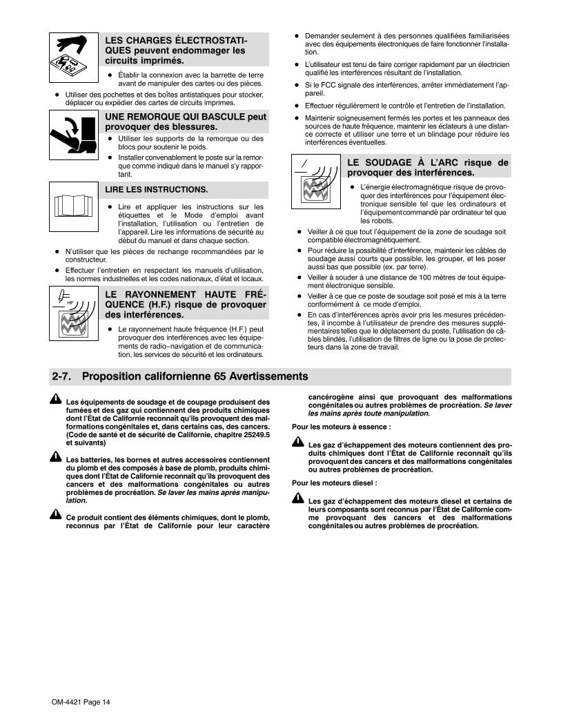
OM-4421 Page 14
LES CHARGES ÉLECTROSTATI-QUES peuvent endommager lescircuits imprimés.
� Établir la connexion avec la barrette de terreavant de manipuler des cartes ou des pièces.
� Utiliser des pochettes et des boîtes antistatiques pour stocker,déplacer ou expédier des cartes de circuits imprimes.
UNE REMORQUE QUI BASCULE peutprovoquer des blessures.� Utiliser les supports de la remorque ou des
blocs pour soutenir le poids.� Installer convenablement le poste sur la remor-
que comme indiqué dans le manuel s’y rappor-tant.
LIRE LES INSTRUCTIONS.
� Lire et appliquer les instructions sur lesétiquettes et le Mode d’emploi avantl’installation, l’utilisation ou l’entretien del’appareil. Lire les informations de sécurité audébut du manuel et dans chaque section.
� N’utiliser que les pièces de rechange recommandées par leconstructeur.
� Effectuer l’entretien en respectant les manuels d’utilisation,les normes industrielles et les codes nationaux, d’état et locaux.
LE RAYONNEMENT HAUTE FRÉ-QUENCE (H.F.) risque de provoquerdes interférences.
� Le rayonnement haute fréquence (H.F.) peutprovoquer des interférences avec les équipe-ments de radio−navigation et de communica-tion, les services de sécurité et les ordinateurs.
� Demander seulement à des personnes qualifiées familiariséesavec des équipements électroniques de faire fonctionner l’installa-tion.
� L’utilisateur est tenu de faire corriger rapidement par un électricienqualifié les interférences résultant de l’installation.
� Si le FCC signale des interférences, arrêter immédiatement l’ap-pareil.
� Effectuer régulièrement le contrôle et l’entretien de l’installation.
� Maintenir soigneusement fermés les portes et les panneaux dessources de haute fréquence, maintenir les éclateurs à une distan-ce correcte et utiliser une terre et un blindage pour réduire lesinterférences éventuelles.
LE SOUDAGE À L’ARC risque deprovoquer des interférences.
� L’énergie électromagnétique risque de provo-quer des interférences pour l’équipement élec-tronique sensible tel que les ordinateurs etl’équipement commandé par ordinateur tel queles robots.
� Veiller à ce que tout l’équipement de la zone de soudage soitcompatible électromagnétiquement.
� Pour réduire la possibilité d’interférence, maintenir les câbles desoudage aussi courts que possible, les grouper, et les poseraussi bas que possible (ex. par terre).
� Veiller à souder à une distance de 100 mètres de tout équipe-ment électronique sensible.
� Veiller à ce que ce poste de soudage soit posé et mis à la terreconformément à ce mode d’emploi.
� En cas d’interférences après avoir pris les mesures précéden-tes, il incombe à l’utilisateur de prendre des mesures supplé-mentaires telles que le déplacement du poste, l’utilisation de câ-bles blindés, l’utilisation de filtres de ligne ou la pose de protec-teurs dans la zone de travail.
2-7. Proposition californienne 65 Avertissements
Les équipements de soudage et de coupage produisent desfumées et des gaz qui contiennent des produits chimiquesdont l’État de Californie reconnaît qu’ils provoquent des mal-formations congénitales et, dans certains cas, des cancers.(Code de santé et de sécurité de Californie, chapitre 25249.5et suivants)
Les batteries, les bornes et autres accessoires contiennentdu plomb et des composés à base de plomb, produits chimi-ques dont l’État de Californie reconnaît qu’ils provoquent descancers et des malformations congénitales ou autresproblèmes de procréation. Se laver les mains après manipu-lation.
Ce produit contient des éléments chimiques, dont le plomb,reconnus par l’État de Californie pour leur caractère
cancérogène ainsi que provoquant des malformationscongénitales ou autres problèmes de procréation. Se laverles mains après toute manipulation.
Pour les moteurs à essence :
Les gaz d’échappement des moteurs contiennent des pro-duits chimiques dont l’État de Californie reconnaît qu’ilsprovoquent des cancers et des malformations congénitalesou autres problèmes de procréation.
Pour les moteurs diesel :
Les gaz d’échappement des moteurs diesel et certains deleurs composants sont reconnus par l’État de Californie com-me provoquant des cancers et des malformationscongénitales ou autres problèmes de procréation.

OM-4421 Page 15
2-8. Principales normes de sécuritéSafety in Welding, Cutting, and Allied Processes, ANSI Standard Z49.1,from Global Engineering Documents (phone: 1-877-413-5184, website:www.global.ihs.com).Safe Practices for the Preparation of Containers and Piping for Weldingand Cutting, American Welding Society Standard AWS F4.1, from Glob-al Engineering Documents (phone: 1-877-413-5184, website:www.global.ihs.com).National Electrical Code, NFPA Standard 70, from National Fire Protec-tion Association, Quincy, MA 02269 (phone: 1-800-344-3555, website:www.nfpa.org and www. sparky.org).Safe Handling of Compressed Gases in Cylinders, CGA Pamphlet P-1,from Compressed Gas Association, 4221 Walney Road, 5th Floor,Chantilly, VA 20151 (phone: 703-788-2700, website:www.cganet.com).Safety in Welding, Cutting, and Allied Processes, CSA StandardW117.2, from Canadian Standards Association, Standards Sales, 5060Spectrum Way, Suite 100, Ontario, Canada L4W 5NS (phone:800-463-6727, website: www.csa-international.org).Battery Chargers, CSA Standard C22.2 NO 107.2−01, from CanadianStandards Association, Standards Sales, 5060 Spectrum Way, Suite100, Ontario, Canada L4W 5NS (phone: 800-463-6727, website:www.csa-international.org).Safe Practice For Occupational And Educational Eye And Face Protec-tion, ANSI Standard Z87.1, from American National Standards Institute,
25 West 43rd Street, New York, NY 10036 (phone: 212-642-4900, web-site: www.ansi.org).Standard for Fire Prevention During Welding, Cutting, and Other HotWork, NFPA Standard 51B, from National Fire Protection Association,Quincy, MA 02269 (phone: 1-800-344-3555, website: www.nfpa.org.For Standards about hydraulic systems, contact the National FluidPower Association, Publications Department, 3333 North MayfairRoad, Suite 211, Milwaukee, WI 53222-3219 (phone: (414) 778-3344,website: www.nfpa.com).
OSHA, Occupational Safety and Health Standards for General Indus-try, Title 29, Code of Federal Regulations (CFR), Part 1910, Subpart Q,and Part 1926, Subpart J, from U.S. Government Printing Office, Super-intendent of Documents, P.O. Box 371954, Pittsburgh, PA 15250-7954(phone: 1-866-512-1800) (there are 10 OSHA Regional Offices—phone for Region 5, Chicago, is 312-353-2220, website:www.osha.gov).U.S. Consumer Product Safety Commission (CPSC), 4330 East WestHighway, Bethesda, MD 20814 (phone: 301-504-7923, website:www.cpsc.gov).Applications Manual for the Revised NIOSH Lifting Equation, The Na-tional Institute for Occupational Safety and Health (NIOSH), 1600Clifton Rd, Atlanta, GA 30333 (phone: 1-800-232-4636, website:www.cdc.gov/NIOSH).
2-9. Informations relatives aux CEM
Le courant électrique qui traverse tout conducteur génère des champsélectromagnétiques (CEM) à certains endroits. Le courant de soudagecrée un CEM autour du circuit et du matériel de soudage. Les CEMpeuvent créer des interférences avec certains implants médicauxcomme des stimulateurs cardiaques. Des mesures de protection pourles porteurs d’implants médicaux doivent être prises: par exemple, desrestrictions d’accès pour les passants ou une évaluation individuelledes risques pour les soudeurs. Tous les soudeurs doivent appliquer lesprocédures suivantes pour minimiser l’exposition aux CEM provenantdu circuit de soudage:
1. Rassembler les câbles en les torsadant ou en les attachant avecdu ruban adhésif ou avec une housse.
2. Ne pas se tenir au milieu des câbles de soudage. Disposer lescâbles d’un côté et à distance de l’opérateur.
3. Ne pas courber et ne pas entourer les câbles autour de votrecorps.
4. Maintenir la tête et le torse aussi loin que possible du matériel ducircuit de soudage.
5. Connecter la pince sur la pièce aussi près que possible de lasoudure.
6. Ne pas travailler à proximité d’une source de soudage, nis’asseoir ou se pencher dessus.
7. Ne pas souder tout en portant la source de soudage ou ledévidoir.
En ce qui concerne les implants médicaux :
Les porteurs d’implants doivent d’abord consulter leur médecin avantde s’approcher des opérations de soudage à l’arc, de soudage parpoints, de gougeage, du coupage plasma ou de chauffage par induc-tion. Si le médecin approuve, il est recommandé de suivre lesprocédures précédentes.
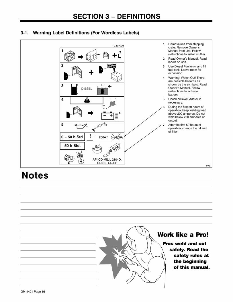
OM-4421 Page 16
SECTION 3 − DEFINITIONS
3-1. Warning Label Definitions (For Wordless Labels)
3/96
1 Remove unit from shippingcrate. Remove Owner’sManual from unit. Followinstructions to install muffler.
2 Read Owner’s Manual. Readlabels on unit.
3 Use Diesel Fuel only, and fillfuel tank. Leave room forexpansion.
4 Warning! Watch Out! Thereare possible hazards asshown by the symbols. ReadOwner’s Manual. Followinstructions to activatebattery.
5 Check oil level. Add oil ifnecessary.
6 During the first 50 hours ofoperation, keep welding loadabove 200 amperes. Do notweld below 200 amperes ofoutput.
7 After the first 50 hours ofoperation, change the oil andoil filter.
+2
1 +
4
DIESEL
API CD-MIL L 2104D,CD/SE, CD/SF
3
S-177 571
0 − 50 h Std. 0 − 200A200A
5
50 h Std.
Notes
Work like a Pro!
Pros weld and cut
safely. Read the
safety rules at
the beginning
of this manual.

OM-4421 Page 17
3-2. Symbols And Definitions
� Some symbols are found only on export products.
Stop EngineFast (Run, Weld/
Power) Slow (Idle) Start Engine
Starting Aid Battery (Engine)Engine OilPressure Engine Oil
Check Injectors/Pump
Check ValveClearance Fuel
Protective Earth(Ground)
Positive NegativeCertified/Trained
Mechanic Welding Arc
A Amperes V Volts Panel/Local Remote
EngineAir Temperature Or
EngineTemperature
OutputAlternating
Current
Stick (SMAW)Welding
Constant Current(CC)
MIG (GMAW)Welding TIG (GTAW)
Time h Hours s Seconds 1 Single Phase
3 Three PhaseRead Operator’s
Manual Circuit ProtectorDo Not SwitchWhile Welding
ElectrodeConnection Work Connection 3
G
Engine-Driven,Three-Phase
Alternator WithRectifier
Hz Hertz
X Duty Cycle U0Rated No Load
Voltage (Average) U2ConventionalLoad Voltage n
Rated LoadSpeed
n1Rated Idle
Speed n0Rated No Load
Speed I Current I2Rated Welding
Current
Contactor On
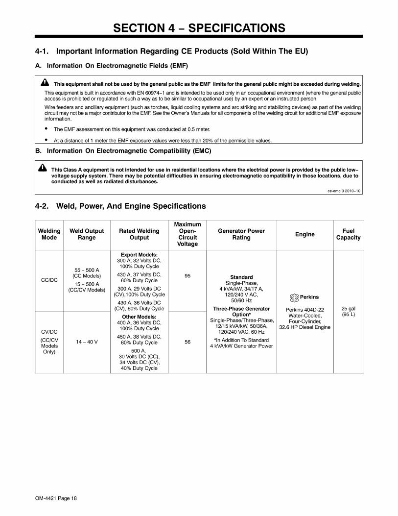
OM-4421 Page 18
SECTION 4 − SPECIFICATIONS
4-1. Important Information Regarding CE Products (Sold Within The EU)
A. Information On Electromagnetic Fields (EMF)
! This equipment shall not be used by the general public as the EMF limits for the general public might be exceeded during welding.
This equipment is built in accordance with EN 60974−1 and is intended to be used only in an occupational environment (where the general publicaccess is prohibited or regulated in such a way as to be similar to occupational use) by an expert or an instructed person.
Wire feeders and ancillary equipment (such as torches, liquid cooling systems and arc striking and stabilizing devices) as part of the weldingcircuit may not be a major contributor to the EMF. See the Owner’s Manuals for all components of the welding circuit for additional EMF exposureinformation.
� The EMF assessment on this equipment was conducted at 0.5 meter.
� At a distance of 1 meter the EMF exposure values were less than 20% of the permissible values.
B. Information On Electromagnetic Compatibility (EMC)
! This Class A equipment is not intended for use in residential locations where the electrical power is provided by the public low−voltage supply system. There may be potential difficulties in ensuring electromagnetic compatibility in those locations, due toconducted as well as radiated disturbances.
ce-emc 3 2010−10
4-2. Weld, Power, And Engine Specifications
WeldingMode
Weld OutputRange
Rated WeldingOutput
MaximumOpen-CircuitVoltage
Generator PowerRating Engine Fuel
Capacity
CC/DC
55 − 500 A(CC Models)
15 − 500 A(CC/CV Models)
Export Models:300 A, 32 Volts DC,100% Duty Cycle
430 A, 37 Volts DC,60% Duty Cycle
300 A, 29 Volts DC(CV),100% Duty Cycle
430 A, 36 Volts DC(CV), 60% Duty Cycle
Other Models:400 A, 36 Volts DC,100% Duty Cycle
450 A, 38 Volts DC,60% Duty Cycle
500 A, 30 Volts DC (CC), 34 Volts DC (CV),40% Duty Cycle
95 StandardSingle-Phase,
4 kVA/kW, 34/17 A,120/240 V AC,
50/60 Hz
Three-Phase GeneratorOption*
Single-Phase/Three-Phase,12/15 kVA/kW, 50/36A,
120/240 VAC, 60 Hz
*In Addition To Standard4 kVA/kW Generator Power
Perkins 404D-22Water-Cooled,Four-Cylinder,
32.6 HP Diesel Engine
Perkins
25 gal(95 L)
CV/DC
(CC/CVModelsOnly)
14 − 40 V 56
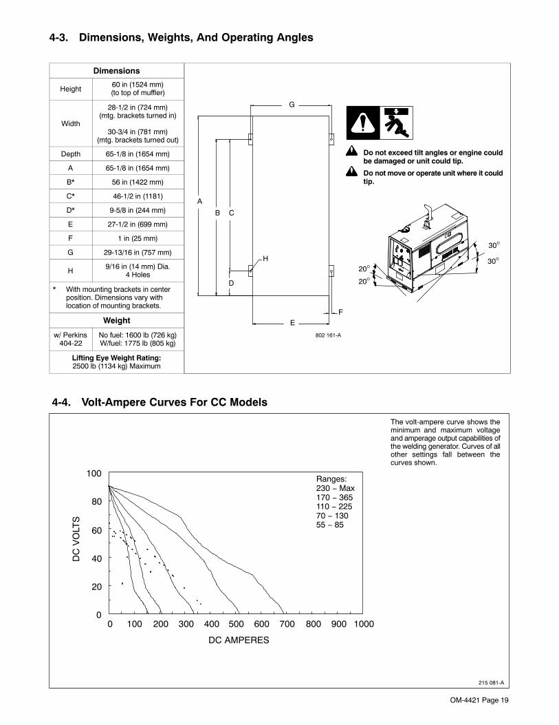
OM-4421 Page 19
4-3. Dimensions, Weights, And Operating Angles
Dimensions
D
B
A
FE
H
G
C
20°20°
30°
30°
! Do not exceed tilt angles or engine couldbe damaged or unit could tip.
! Do not move or operate unit where it couldtip.
802 161-A
Height60 in (1524 mm)(to top of muffler)
Width
28-1/2 in (724 mm)(mtg. brackets turned in)
30-3/4 in (781 mm)(mtg. brackets turned out)
Depth 65-1/8 in (1654 mm)
A 65-1/8 in (1654 mm)
B* 56 in (1422 mm)
C* 46-1/2 in (1181)
D* 9-5/8 in (244 mm)
E 27-1/2 in (699 mm)
F 1 in (25 mm)
G 29-13/16 in (757 mm)
H9/16 in (14 mm) Dia.
4 Holes
* With mounting brackets in centerposition. Dimensions vary withlocation of mounting brackets.
Weight
w/ Perkins404-22
No fuel: 1600 lb (726 kg)W/fuel: 1775 lb (805 kg)
Lifting Eye Weight Rating:2500 lb (1134 kg) Maximum
4-4. Volt-Ampere Curves For CC Models
215 081-A
The volt-ampere curve shows theminimum and maximum voltageand amperage output capabilities ofthe welding generator. Curves of allother settings fall between thecurves shown.
DC AMPERES
DC
VO
LTS
100
80
60
40
20
00 100 200 300 400 500 600 700 800 900 1000
Ranges:230 − Max170 − 365110 − 22570 − 13055 − 85
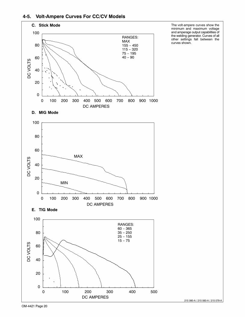
OM-4421 Page 20
4-5. Volt-Ampere Curves For CC/CV Models
215 080-A / 215 083-A / 215 079-A
The volt-ampere curves show theminimum and maximum voltageand amperage output capabilities ofthe welding generator. Curves of allother settings fall between thecurves shown.
C. Stick Mode
D. MIG Mode
E. TIG Mode
DC
VO
LTS
DC AMPERES
DC
VO
LTS
DC AMPERES
DC
VO
LTS
DC AMPERES
100
80
60
40
20
0
0 100 200 300 400 500 600 700 800 900 1000
100
80
60
40
20
00 100 200 300 400 500 600 700 800 900 1000
MAX
MIN
100
80
60
40
20
00 100 200 300 400 500
RANGES:MAX155 − 450115 − 32075 − 19540 − 90
RANGES:60 − 36535 − 25025 − 15515 − 75
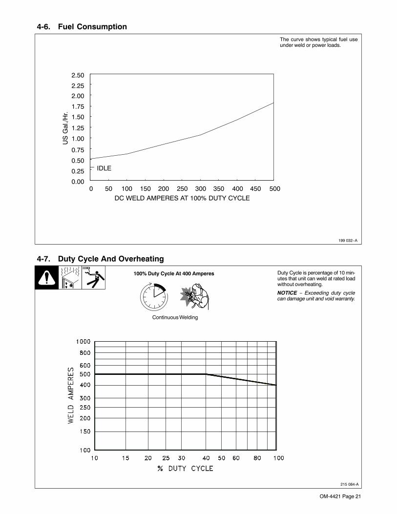
OM-4421 Page 21
4-6. Fuel Consumption
The curve shows typical fuel useunder weld or power loads.
199 032−A
DC WELD AMPERES AT 100% DUTY CYCLE
US
Gal
./Hr.
0 50 100 150 200 250 300 350 400 450 5000.00
0.25
0.50
0.75
1.00
1.25
1.50
1.75
2.00
2.25
2.50
IDLE
Continuous Welding
4-7. Duty Cycle And Overheating
Duty Cycle is percentage of 10 min-utes that unit can weld at rated loadwithout overheating.
NOTICE − Exceeding duty cyclecan damage unit and void warranty.
100% Duty Cycle At 400 Amperes
215 084-A
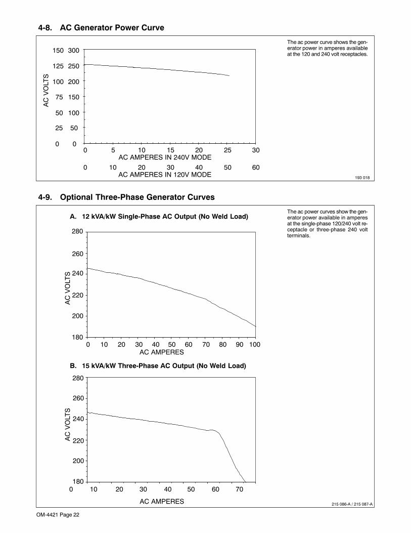
OM-4421 Page 22
4-8. AC Generator Power Curve
193 018
The ac power curve shows the gen-erator power in amperes availableat the 120 and 240 volt receptacles.
0
50
100
150
200
250
300
0 5 10 15 20 25 30AC AMPERES IN 240V MODE
AC
VO
LTS
0
25
50
75
100
150
125
0 10 20 30 40 50 60AC AMPERES IN 120V MODE
4-9. Optional Three-Phase Generator Curves
215 086-A / 215 087-A
The ac power curves show the gen-erator power available in amperesat the single-phase 120/240 volt re-ceptacle or three-phase 240 voltterminals.
A. 12 kVA/kW Single-Phase AC Output (No Weld Load)
B. 15 kVA/kW Three-Phase AC Output (No Weld Load)
AC
VO
LTS
AC
VO
LTS
AC AMPERES
AC AMPERES
280
260
240
220
200
1800 10 20 30 40 50 60 70 80 90 100
0 10 20 30 40 50 60 70
280
260
240
220
200
180
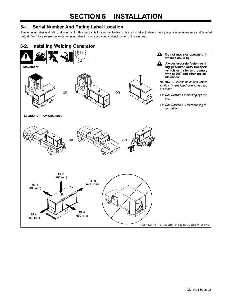
OM-4421 Page 23
SECTION 5 − INSTALLATION5-1. Serial Number And Rating Label LocationThe serial number and rating information for this product is located on the front. Use rating label to determine input power requirements and/or ratedoutput. For future reference, write serial number in space provided on back cover of this manual.
! Do not move or operate unitwhere it could tip.
! Always securely fasten weld-ing generator onto transportvehicle or trailer and complywith all DOT and other applica-ble codes.
NOTICE − Do not install unit whereair flow is restricted or engine mayoverheat.
� See Section 4-3 for lifting eye rat-ing.
� See Section 5-3 for mounting in-formation.
install3 2008-01 − Ref. 800 652 / Ref. 800 477-A / 803 274 / 804 712
18 in(460 mm)
18 in(460 mm)
18 in(460 mm)
18 in(460 mm)
18 in(460 mm)
Movement
5-2. Installing Welding Generator
OR OR
OR
Location/Airflow Clearance
OR
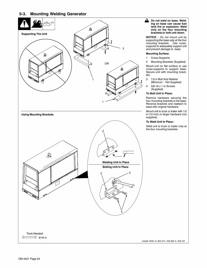
OM-4421 Page 24
5-3. Mounting Welding Generator
Tools Needed:
9/16 in
2
2
4
Welding Unit In Place
Bolting Unit In Place
! Do not weld on base. Weld-ing on base can cause fueltank fire or explosion. Weldonly on the four mountingbrackets or bolt unit down.
NOTICE − Do not mount unit bysupporting the base only at the fourmounting brackets. Use cross-supports to adequately support unitand prevent damage to base.
Mounting Surface:
1 Cross-Supports
2 Mounting Brackets (Supplied)
Mount unit on flat surface or usecross-supports to support base.Secure unit with mounting brack-ets.
3 1/2 in Bolt And Washer(Minimum − Not Supplied)
4 3/8-16 x 1 in Screws(Supplied)
To Bolt Unit In Place:
Remove hardware securing thefour mounting brackets to the base.Reverse brackets and reattach tobase with original hardware.
Mount unit to truck or trailer with 1/2in (12 mm) or larger hardware (notsupplied).
To Weld Unit In Place:
Weld unit to truck or trailer only atthe four mounting brackets.
1
2
Supporting The Unit
Using Mounting Brackets
install3 2008--01 803 274 / 200 864-A / 803 231
1
OR
3
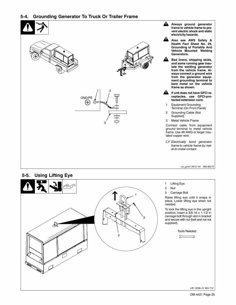
OM-4421 Page 25
! Always ground generatorframe to vehicle frame to pre-vent electric shock and staticelectricity hazards.
! Also see AWS Safety &Health Fact Sheet No. 29,Grounding of Portable AndVehicle Mounted WeldingGenerators.
! Bed liners, shipping skids,and some running gear insu-late the welding generatorfrom the vehicle frame. Al-ways connect a ground wirefrom the generator equip-ment grounding terminal tobare metal on the vehicleframe as shown.
! If unit does not have GFCI re-ceptacles, use GFCI-pro-tected extension cord.
1 Equipment GroundingTerminal (On Front Panel)
2 Grounding Cable (NotSupplied)
3 Metal Vehicle Frame
Connect cable from equipmentground terminal to metal vehicleframe. Use #8 AWG or larger insu-lated copper wire.
� Electrically bond generatorframe to vehicle frame by met-al-to-metal contact.
5-4. Grounding Generator To Truck Or Trailer Frame
rot_grnd1 2010−04 − 800 652-D
1
3
2
GND/PE
5-5. Using Lifting Eye
Lift1 2008−01 804 712
1 Lifting Eye
2 Nut
3 Carriage Bolt
Raise lifting eye until it snaps inplace. Lower lifting eye when notneeded.
To lock the lifting eye in the uprightposition, insert a 3/8-16 x 1-1/2 incarriage bolt through slot in bracketand secure with nut (bolt and nut notsupplied).
Tools Needed:
2
1
3
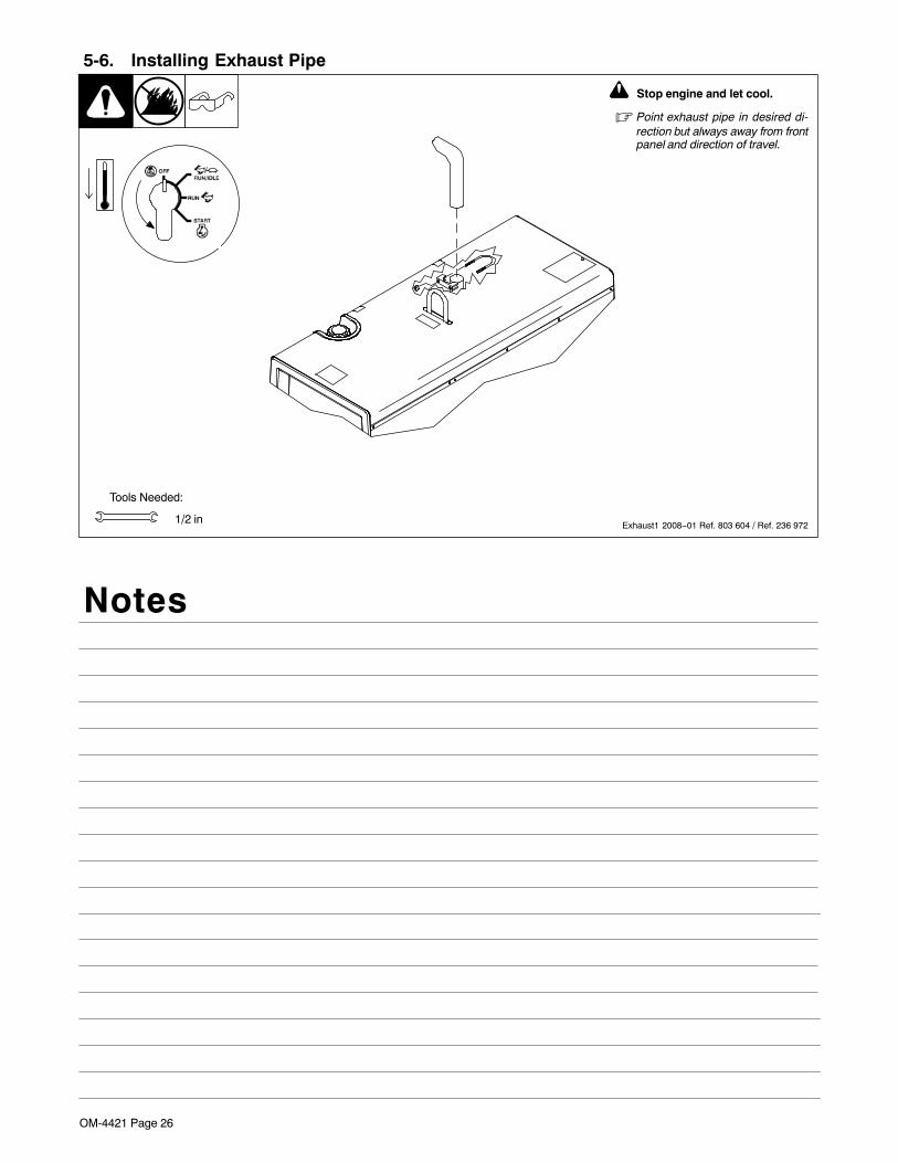
OM-4421 Page 26
5-6. Installing Exhaust Pipe
1/2 in
Tools Needed:
Exhaust1 2008−01 Ref. 803 604 / Ref. 236 972
! Stop engine and let cool.
� Point exhaust pipe in desired di-rection but always away from frontpanel and direction of travel.
Notes
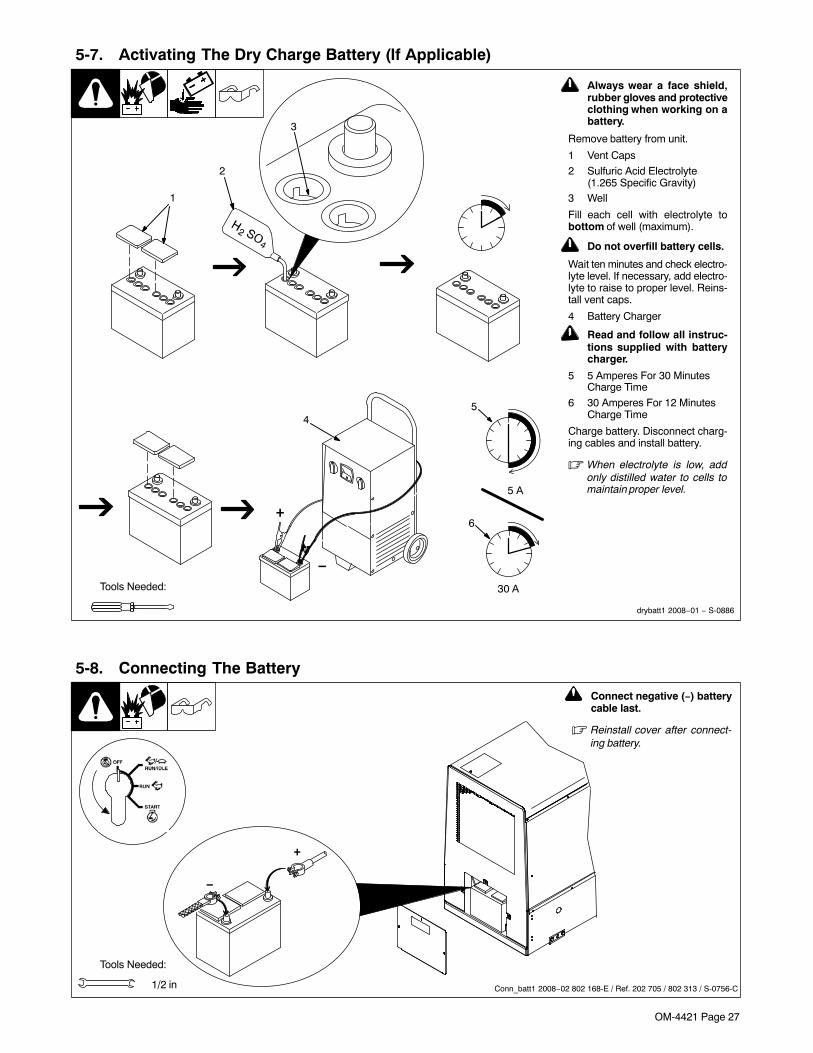
OM-4421 Page 27
5-7. Activating The Dry Charge Battery (If Applicable)
! Always wear a face shield,rubber gloves and protectiveclothing when working on abattery.
Remove battery from unit.
1 Vent Caps
2 Sulfuric Acid Electrolyte(1.265 Specific Gravity)
3 Well
Fill each cell with electrolyte tobottom of well (maximum).
! Do not overfill battery cells.
Wait ten minutes and check electro-lyte level. If necessary, add electro-lyte to raise to proper level. Reins-tall vent caps.
4 Battery Charger
! Read and follow all instruc-tions supplied with batterycharger.
5 5 Amperes For 30 MinutesCharge Time
6 30 Amperes For 12 MinutesCharge Time
Charge battery. Disconnect charg-ing cables and install battery.
� When electrolyte is low, addonly distilled water to cells tomaintain proper level.
1
Tools Needed:
2
4
+
−
3
drybatt1 2008−01 − S-0886
5
6
30 A
5 A
5-8. Connecting The Battery
1/2 in
−
+
Tools Needed:
! Connect negative (−) batterycable last.
� Reinstall cover after connect-ing battery.
Conn_batt1 2008−02 802 168-E / Ref. 202 705 / 802 313 / S-0756-C
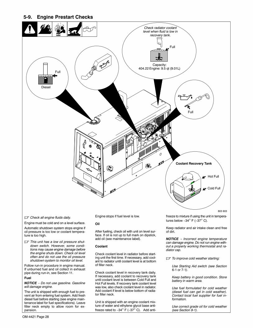
OM-4421 Page 28
5-9. Engine Prestart Checks
� Check all engine fluids daily.
Engine must be cold and on a level surface.
Automatic shutdown system stops engine ifoil pressure is too low or coolant tempera-ture is too high.
� This unit has a low oil pressure shut-down switch. However, some condi-tions may cause engine damage beforethe engine shuts down. Check oil leveloften and do not use the oil pressureshutdown system to monitor oil level.
Follow run-in procedure in engine manual.If unburned fuel and oil collect in exhaustpipe during run-in, see Section 11.
Fuel
NOTICE − Do not use gasoline. Gasolinewill damage engine.
The unit is shipped with enough fuel to pre-vent air from entering fuel system. Add freshdiesel fuel before starting (see engine main-tenance label for fuel specifications). Leavefiller neck empty to allow room for ex-pansion.
Engine stops if fuel level is low.
Oil
After fueling, check oil with unit on level sur-face. If oil is not up to full mark on dipstick,add oil (see maintenance label).
Coolant
Check coolant level in radiator before start-ing unit the first time. If necessary, add cool-ant to radiator until coolant level is at bottomof filler neck.
Check coolant level in recovery tank daily.If necessary, add coolant to recovery tankuntil coolant level is between Cold Full andHot Full levels. If recovery tank coolant levelwas low, also check coolant level in radiator.Add coolant if level is below bottom of radia-tor filler neck.
Unit is shipped with an engine coolant mix-ture of water and ethylene glycol base anti-freeze rated to −34° F (−37° C). Add anti-
freeze to mixture if using the unit in tempera-tures below −34° F (−37° C).
Keep radiator and air intake clean and freeof dirt.
NOTICE − Incorrect engine temperaturecan damage engine. Do not run engine with-out a properly working thermostat and ra-diator cap.
� To improve cold weather starting:
Use Starting Aid switch (see Section6-1 or 7-1).
Keep battery in good condition. Storebattery in warm area.
Use fuel formulated for cold weather(diesel fuel can gel in cold weather).Contact local fuel supplier for fuel in-formation.
Use correct grade oil for cold weather(see Section 9-1).
Full
803 603
Full
Capacity:404.22 Engine: 9.5 qt (9.01L)
Diesel
Full
Hot Full
Cold Full
Check radiator coolantlevel when fluid is low in
recovery tank.
Coolant Recovery Tank
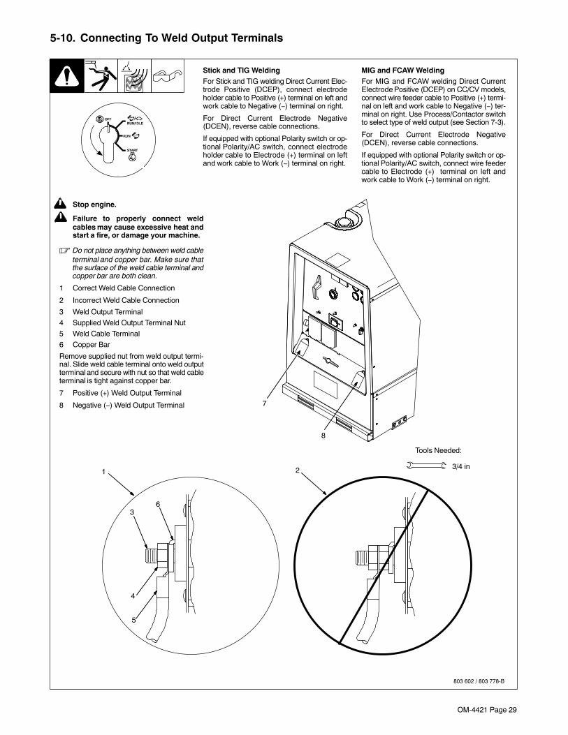
OM-4421 Page 29
5-10. Connecting To Weld Output Terminals
803 602 / 803 778-B
Tools Needed:
2 3/4 in1
MIG and FCAW WeldingFor MIG and FCAW welding Direct CurrentElectrode Positive (DCEP) on CC/CV models,connect wire feeder cable to Positive (+) termi-nal on left and work cable to Negative (−) ter-minal on right. Use Process/Contactor switchto select type of weld output (see Section 7-3).
For Direct Current Electrode Negative(DCEN), reverse cable connections.
If equipped with optional Polarity switch or op-tional Polarity/AC switch, connect wire feedercable to Electrode (+) terminal on left andwork cable to Work (−) terminal on right.
6
4
5
3
! Stop engine.
! Failure to properly connect weldcables may cause excessive heat andstart a fire, or damage your machine.
� Do not place anything between weld cableterminal and copper bar. Make sure thatthe surface of the weld cable terminal andcopper bar are both clean.
1 Correct Weld Cable Connection
2 Incorrect Weld Cable Connection
3 Weld Output Terminal
4 Supplied Weld Output Terminal Nut
5 Weld Cable Terminal
6 Copper Bar
Remove supplied nut from weld output termi-nal. Slide weld cable terminal onto weld outputterminal and secure with nut so that weld cableterminal is tight against copper bar.
7 Positive (+) Weld Output Terminal
8 Negative (−) Weld Output Terminal
Stick and TIG WeldingFor Stick and TIG welding Direct Current Elec-trode Positive (DCEP), connect electrodeholder cable to Positive (+) terminal on left andwork cable to Negative (−) terminal on right.
For Direct Current Electrode Negative(DCEN), reverse cable connections.
If equipped with optional Polarity switch or op-tional Polarity/AC switch, connect electrodeholder cable to Electrode (+) terminal on leftand work cable to Work (−) terminal on right.
7
8
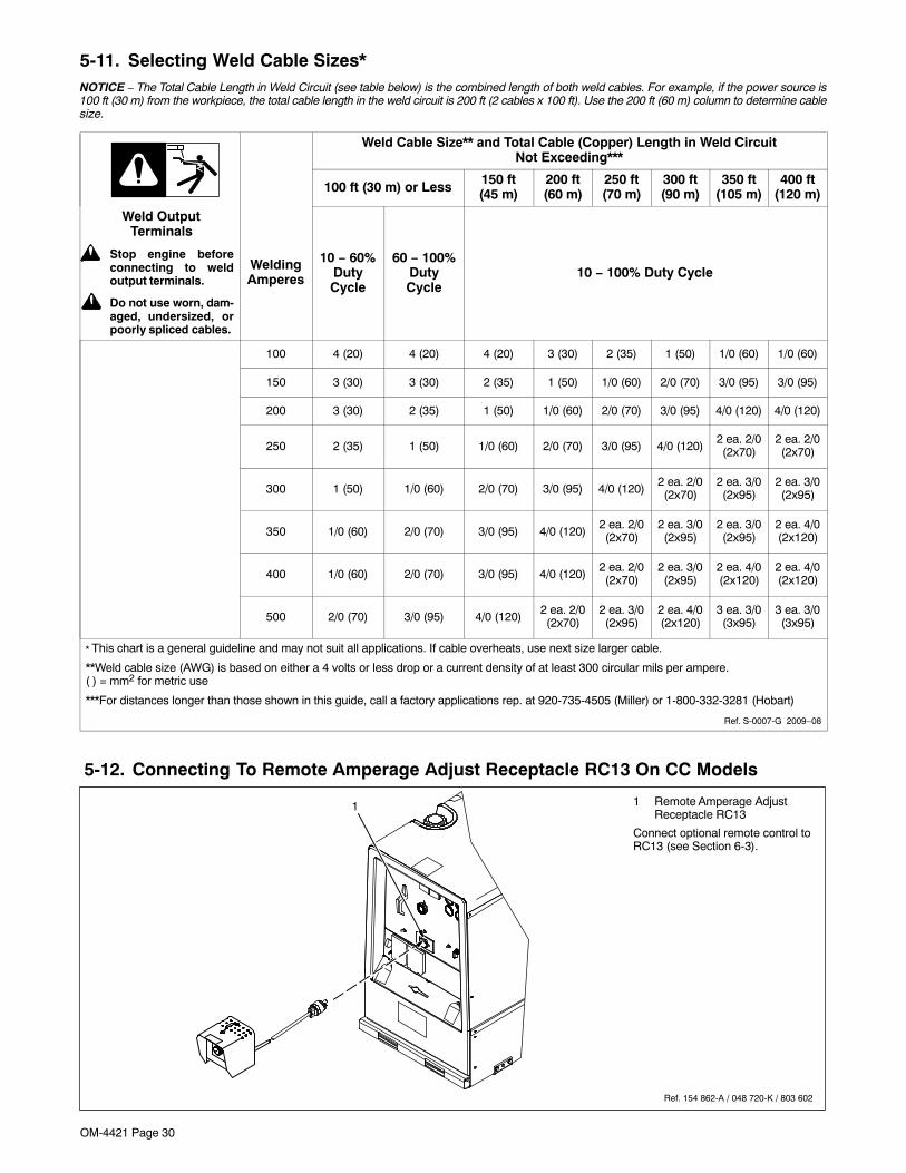
OM-4421 Page 30
5-11. Selecting Weld Cable Sizes*NOTICE − The Total Cable Length in Weld Circuit (see table below) is the combined length of both weld cables. For example, if the power source is100 ft (30 m) from the workpiece, the total cable length in the weld circuit is 200 ft (2 cables x 100 ft). Use the 200 ft (60 m) column to determine cablesize.
Weld Cable Size** and Total Cable (Copper) Length in Weld CircuitNot Exceeding***
100 ft (30 m) or Less 150 ft(45 m)
200 ft(60 m)
250 ft(70 m)
300 ft(90 m)
350 ft(105 m)
400 ft(120 m)
Weld OutputTerminals
! Stop engine beforeconnecting to weldoutput terminals.
! Do not use worn, dam-aged, undersized, orpoorly spliced cables.
WeldingAmperes
10 − 60%DutyCycle
60 − 100%DutyCycle
10 − 100% Duty Cycle
100 4 (20) 4 (20) 4 (20) 3 (30) 2 (35) 1 (50) 1/0 (60) 1/0 (60)
150 3 (30) 3 (30) 2 (35) 1 (50) 1/0 (60) 2/0 (70) 3/0 (95) 3/0 (95)
200 3 (30) 2 (35) 1 (50) 1/0 (60) 2/0 (70) 3/0 (95) 4/0 (120) 4/0 (120)
250 2 (35) 1 (50) 1/0 (60) 2/0 (70) 3/0 (95) 4/0 (120)2 ea. 2/0(2x70)
2 ea. 2/0(2x70)
300 1 (50) 1/0 (60) 2/0 (70) 3/0 (95) 4/0 (120)2 ea. 2/0(2x70)
2 ea. 3/0(2x95)
2 ea. 3/0(2x95)
350 1/0 (60) 2/0 (70) 3/0 (95) 4/0 (120)2 ea. 2/0(2x70)
2 ea. 3/0(2x95)
2 ea. 3/0(2x95)
2 ea. 4/0(2x120)
400 1/0 (60) 2/0 (70) 3/0 (95) 4/0 (120)2 ea. 2/0(2x70)
2 ea. 3/0(2x95)
2 ea. 4/0(2x120)
2 ea. 4/0(2x120)
500 2/0 (70) 3/0 (95) 4/0 (120)2 ea. 2/0(2x70)
2 ea. 3/0(2x95)
2 ea. 4/0(2x120)
3 ea. 3/0(3x95)
3 ea. 3/0(3x95)
* This chart is a general guideline and may not suit all applications. If cable overheats, use next size larger cable.
**Weld cable size (AWG) is based on either a 4 volts or less drop or a current density of at least 300 circular mils per ampere.( ) = mm2 for metric use
***For distances longer than those shown in this guide, call a factory applications rep. at 920-735-4505 (Miller) or 1-800-332-3281 (Hobart)
Ref. S-0007-G 2009−08
5-12. Connecting To Remote Amperage Adjust Receptacle RC13 On CC Models
Ref. 154 862-A / 048 720-K / 803 602
1 Remote Amperage AdjustReceptacle RC13
Connect optional remote control toRC13 (see Section 6-3).
1

OM-4421 Page 31
5-13. Connecting To Remote 14 Receptacle RC14 On CC/CV Models
Ref. 803 602
OR
Socket* Socket Information
24 VOLTS AC
A 24 volts AC. Protected by sup-plementary protector CB5.
B Contact closure to A completes24 volt AC contactor controlcircuit.
REMOTEOUTPUT
CONTROL
C Output to remote control:+10volts DC in MIG or Stick mode;0 to +10 volts DC in TIG mode.
D Remote control circuit common.
E DC input command signal: 0 to+10 volts from min. to max. ofremote control with Voltage/Amperage Adjust control atmax.
115 VOLTS ACI
115 volts, 10 amperes, 60 HzAC. Protected by supplementa-ry protector CB6.
JContact closure to I completes115 volt AC contactor controlcircuit.
GND K Chassis common.
NEUTRAL G Circuit common for 24 and 115volt AC circuit.
*The remaining sockets are not used.
Notes
Over 80,000 trained
since 1930!400 Trade Square East, Troy, Ohio 45373
1-800-332-9448 www.welding.org
Start Your Professional
Welding Career Now!
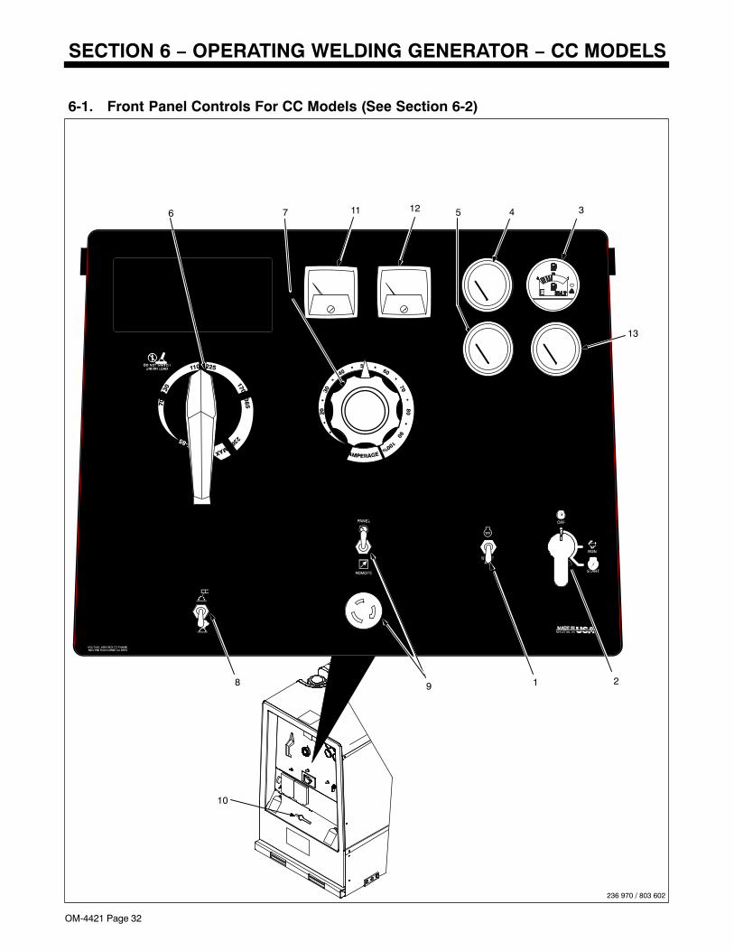
OM-4421 Page 32
SECTION 6 − OPERATING WELDING GENERATOR − CC MODELS
6-1. Front Panel Controls For CC Models (See Section 6-2)
12
236 970 / 803 602
11
218 9
76 45 3
10
13
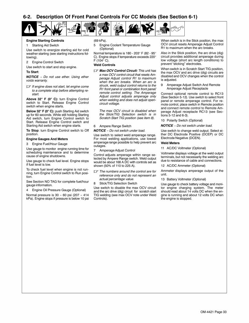
OM-4421 Page 33
6-2. Description Of Front Panel Controls For CC Models (See Section 6-1)
Engine Starting Controls1 Starting Aid SwitchUse switch to energize starting aid for coldweather starting (see starting instructions fol-lowing).
2 Engine Control Switch
Use switch to start and stop engine.
To Start:
NOTICE − Do not use ether. Using ethervoids warranty.
� If engine does not start, let engine cometo a complete stop before attempting re-start.
Above 32� F (0� C): turn Engine Controlswitch to Start. Release Engine Controlswitch when engine starts.
Below 32� F (0� C): push Starting Aid switchup for 60 seconds. While still holding StartingAid switch, turn Engine Control switch toStart. Release Engine Control switch andStarting Aid switch when engine starts.
To Stop: turn Engine Control switch to Offposition.
Engine Gauges And Meters
3 Engine Fuel/Hour Gauge
Use gauge to monitor engine running time forscheduling maintenance and to determinecause of engine shutdowns.
Use gauge to check fuel level. Engine stopsif fuel level is low.
To check fuel level when engine is not run-ning, turn Engine Control switch to Run posi-tion.
See Section NO TAG for complete fuel/hourgauge information.
4 Engine Oil Pressure Gauge (Optional)
Normal pressure is 30 − 60 psi (207 − 414kPa). Engine stops if pressure is below 10 psi
(69 kPa).5 Engine Coolant Temperature Gauge
(Optional)Normal temperature is 180 - 203° F (82 - 95°C). Engine stops if temperature exceeds 220°F (104° C).Weld Controls
� Max OCV Control Circuit: This unit hasa max OCV control circuit that resets Am-perage Adjust control R1 to maximumwhen the arc breaks. When an arc isstruck, weld output control returns to theR1 front panel or combination front panel/remote control setting. The AmperageAdjust control adjusts amperage onlywhen welding and does not adjust open-circuit voltage.
The max OCV circuit is disabled whenthe Stick/TIG Selection switch is inScratch Start TIG position (see item 8).
6 Ampere Range SwitchNOTICE − Do not switch under load.Use switch to select weld amperage range.For most welding applications, use lowestamperage range possible to help prevent arcoutages.7 Amperage Adjust ControlControl adjusts amperage within range se-lected by Ampere Range switch. Weld outputwould be about 168 A DC with controls set asshown (50% of 110 to 225 A).
� The numbers around the control are forreference only and do not represent anactual percentage value.
8 Stick/TIG Selection SwitchUse switch to disable the max OCV circuitand the arc drive (dig) circuit for scratch startTIG welding (see max OCV note under WeldControls).
When switch is in the Stick position, the maxOCV circuit resets Amperage Adjust ControlR1 to maximum when the arc breaks.
Also in the Stick position, the arc drive (dig)circuit provides additional amperage duringlow voltage (short arc length conditions) toprevent “sticking” electrodes.
When switch is in Scratch Start TIG position,the max OCV and arc drive (dig) circuits aredisabled and OCV changes when the controlis adjusted.
9 Amperage Adjust Switch And RemoteAmperage Adjust Receptacle
Connect optional remote control to RC13(See Section 5-12). Use switch to select frontpanel or remote amperage control. For re-mote control, place switch in Remote positionand connect remote control to Remote Am-perage Adjust receptacle RC13 (see Sec-tions 5-12 and 6-3).
10 Polarity Switch (Optional)
NOTICE − Do not switch under load.
Use switch to change weld output. Select ei-ther DC Electrode Positive (DCEP) or DCElectrode Negative (DCEN).
Weld Meters
11 AC/DC Voltmeter (Optional)
Voltmeter displays voltage at the weld outputterminals, but not necessarily the welding arcdue to resistance of cable and connections.
12 AC/DC Ammeter (Optional)
Ammeter displays amperage output of theunit.
13 Battery Voltmeter (Optional)
Use gauge to check battery voltage and moni-tor engine charging system. The metershould read about 14 volts DC when the en-gine is running and about 12 volts DC whenthe engine is stopped.
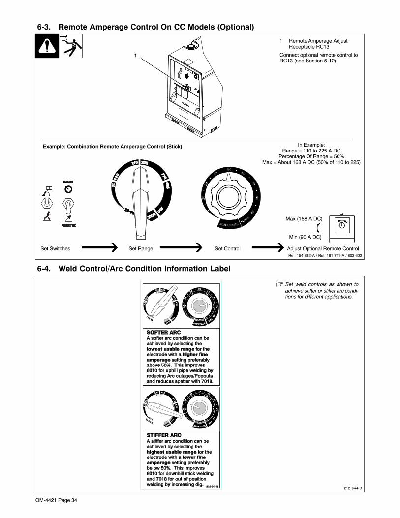
OM-4421 Page 34
6-3. Remote Amperage Control On CC Models (Optional)
1 Remote Amperage AdjustReceptacle RC13
Connect optional remote control toRC13 (see Section 5-12).
Example: Combination Remote Amperage Control (Stick)
Adjust Optional Remote ControlSet Switches Set Range Set ControlRef. 154 862-A / Ref. 181 711-A / 803 602
In Example:Range = 110 to 225 A DC
Percentage Of Range = 50%Max = About 168 A DC (50% of 110 to 225)
Max (168 A DC)
Min (90 A DC)
1
6-4. Weld Control/Arc Condition Information Label
� Set weld controls as shown toachieve softer or stiffer arc condi-tions for different applications.
212 944-B

OM-4421 Page 35
Notes
BUTTBUTTBUTT BUTT
T−JOINT T−JOINT
T−JOINT T−JOINT
FILLET
GROOVE
FLAT VERTICALHORIZONTAL OVERHEADWELD POSITION:
WELD JOINTTYPES
Ref. AWS/ANSI D1.1
1G
1F
2G
2F
3G
3F
4G
4F
Ref. 804 248-A
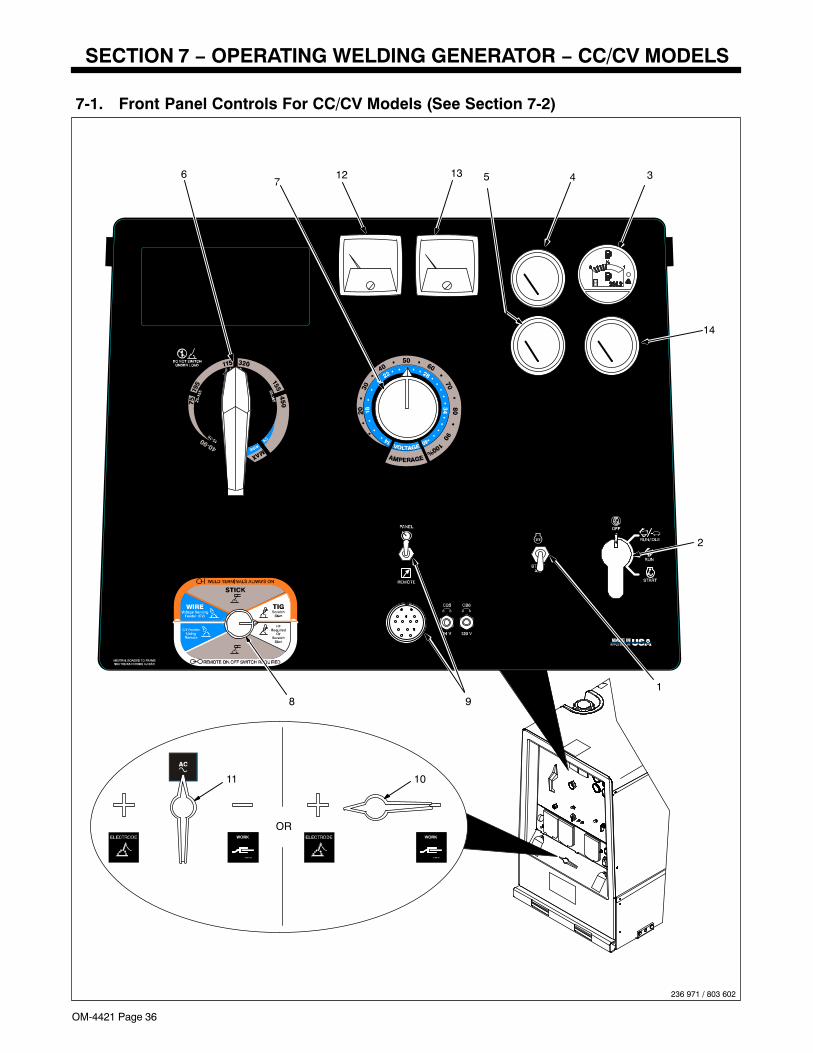
OM-4421 Page 36
SECTION 7 − OPERATING WELDING GENERATOR − CC/CV MODELS
7-1. Front Panel Controls For CC/CV Models (See Section 7-2)
236 971 / 803 602
2
19
14
76 45
8
13
OR
12 3
1011
OM-4421 Page 37
7-2. Description Of Front Panel Controls For CC/CV Models (See Section 7-1)
Engine Starting Controls
1 Starting Aid Switch
Use switch to energize starting aid for coldweather starting (see starting instructions fol-lowing).
2 Engine Control Switch
Use switch to start engine, select enginespeed ( if unit has auto idle option), and stopengine.
In Run position, engine runs at weld/powerspeed. In Run/Idle position (optional), engineruns at idle speed at no load and weld speedwith load applied.
To Start:
NOTICE − Do not use ether. Using ethervoids warranty.
� If engine does not start, let engine cometo a complete stop before attempting re-start.
Above 32� F (0� C): turn Engine Controlswitch to Start. Release Engine Controlswitch when engine starts.
Below 32� F (0� C): push Starting Aid switchup for 60 seconds. While still holding StartingAid switch, turn Engine Control switch toStart. Release Engine Control switch andStarting Aid switch when engine starts.
To Stop: turn Engine Control switch to Offposition.
Engine Gauges And Meters
3 Engine Fuel/Hour Gauge
Use gauge to monitor engine running time forscheduling maintenance and to determinecause of engine shutdowns.
Use gauge to check fuel level. Engine stopsif fuel level is low.
To check fuel level when engine is not run-ning, turn Engine Control switch to Run orRun/Idle position.
See Section NO TAG for complete fuel/hourgauge information.
4 Engine Coolant Temperature Gauge(Optional)
Normal temperature is 180 - 203° F (82 - 95°C). Engine stops if temperature exceeds 220°F (104° C).
5 Engine Oil Pressure Gauge (Optional)
Normal pressure is 30 − 60 psi (207 − 414kPa). Engine stops if pressure is below 10 psi(69 kPa).
Weld Controls
6 Process/Contactor Switch
See Section 7-3 for Process/Contactorswitch information.
7 Ampere Range Switch
NOTICE − Do not switch under load.
Use switch to select weld amperage range.
Use the lowest four ranges for Stick and TIGwelding. Read the upper set of numbers ateach range for Stick welding and the lower setat each range for TIG welding.
Use the highest range for MIG welding and forcutting and gouging (CAC-A).
For most welding applications, use lowestamperage range possible to help prevent arcoutages.
8 Voltage/Amperage Adjust Control
With Process/Contactor switch in any Stick orTIG setting, use control to adjust amperagewithin range selected by Ampere Rangeswitch. With Process/Contactor switch in anyMIG position, use control to adjust voltage.With Voltage/Amperage Adjust Switch in Re-mote position, control limits the remote am-perage in TIG mode, but has no effect in Stickand MIG modes.
Weld output would be about 218 A DC withcontrols set as shown (50% of 115 to 320 A).
� The numbers around the control are forreference only and do not represent anactual percentage value.
9 Voltage/Amperage Adjust Switch AndRemote 14 Receptacle
Use switch to select front panel or remotevoltage/amperage control. For remote con-trol, place switch in Remote position and con-nect remote control to Remote 14 receptacleRC14 (see Sections 5-13 and 7-4).
10 Polarity Switch (Optional)
NOTICE − Do not switch under load.
Use Polarity switch to change weld output.Select either DC Electrode Positive (DCEP)or DC Electrode Negative (DCEN).
11 Polarity/AC Switch (Optional)
! Electric shock can kill.
! Do not use AC output in damp areas,if movement is confined, or if there isa danger of falling.
! Use AC output ONLY if required for thewelding process. If AC output is re-quired, use remote output control ifpresent on unit.
NOTICE − Do not switch under load.
Use Polarity/AC switch to select AC or DCweld output and DC weld output polarity. ForDirect Current Electrode Negative (DCEN),turn switch to − (Negative) position. For DirectCurrent Electrode Positive (DCEP), turnswitch to + (Positive) position. For weld pro-cesses that require alternating current (AC),use AC position.
Weld Meters
12 AC/DC Voltmeter (Optional)
Voltmeter displays voltage at the weld outputterminals, but not necessarily the welding arcdue to resistance of cable and connections.
13 AC/DC Ammeter (Optional)
Ammeter displays amperage output of theunit.
14 Battery Voltmeter (Optional)
Use gauge to check battery voltage and moni-tor engine charging system. The metershould read about 14 volts DC when the en-gine is running and about 12 volts DC whenthe engine is stopped.
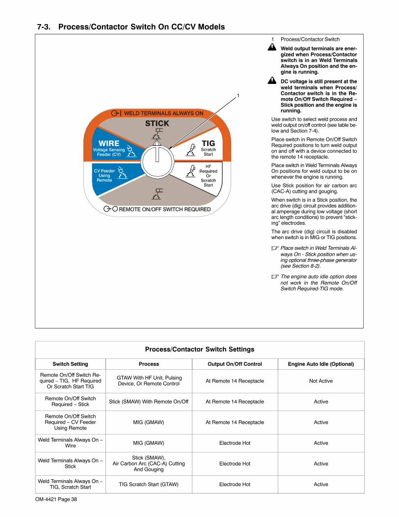
OM-4421 Page 38
7-3. Process/Contactor Switch On CC/CV Models1 Process/Contactor Switch
! Weld output terminals are ener-gized when Process/Contactorswitch is in an Weld TerminalsAlways On position and the en-gine is running.
! DC voltage is still present at theweld terminals when Process/Contactor switch is in the Re-mote On/Off Switch Required −Stick position and the engine isrunning.
Use switch to select weld process andweld output on/off control (see table be-low and Section 7-4).
Place switch in Remote On/Off SwitchRequired positions to turn weld outputon and off with a device connected tothe remote 14 receptacle.
Place switch in Weld Terminals AlwaysOn positions for weld output to be onwhenever the engine is running.
Use Stick position for air carbon arc(CAC-A) cutting and gouging.
When switch is in a Stick position, thearc drive (dig) circuit provides addition-al amperage during low voltage (shortarc length conditions) to prevent “stick-ing” electrodes.
The arc drive (dig) circuit is disabledwhen switch is in MIG or TIG positions.
� Place switch in Weld Terminals Al-ways On - Stick position when us-ing optional three-phase generator(see Section 8-2).
� The engine auto idle option doesnot work in the Remote On/OffSwitch Required-TIG mode.
1
Process/Contactor Switch Settings
Switch Setting Process Output On/Off Control Engine Auto Idle (Optional)
Remote On/Off Switch Re-quired − TIG, HF Required
Or Scratch Start TIG
GTAW With HF Unit, PulsingDevice, Or Remote Control At Remote 14 Receptacle Not Active
Remote On/Off SwitchRequired − Stick Stick (SMAW) With Remote On/Off At Remote 14 Receptacle Active
Remote On/Off SwitchRequired − CV Feeder
Using RemoteMIG (GMAW) At Remote 14 Receptacle Active
Weld Terminals Always On −Wire MIG (GMAW) Electrode Hot Active
Weld Terminals Always On −Stick
Stick (SMAW),Air Carbon Arc (CAC-A) Cutting
And GougingElectrode Hot Active
Weld Terminals Always On −TIG, Scratch Start TIG Scratch Start (GTAW) Electrode Hot Active
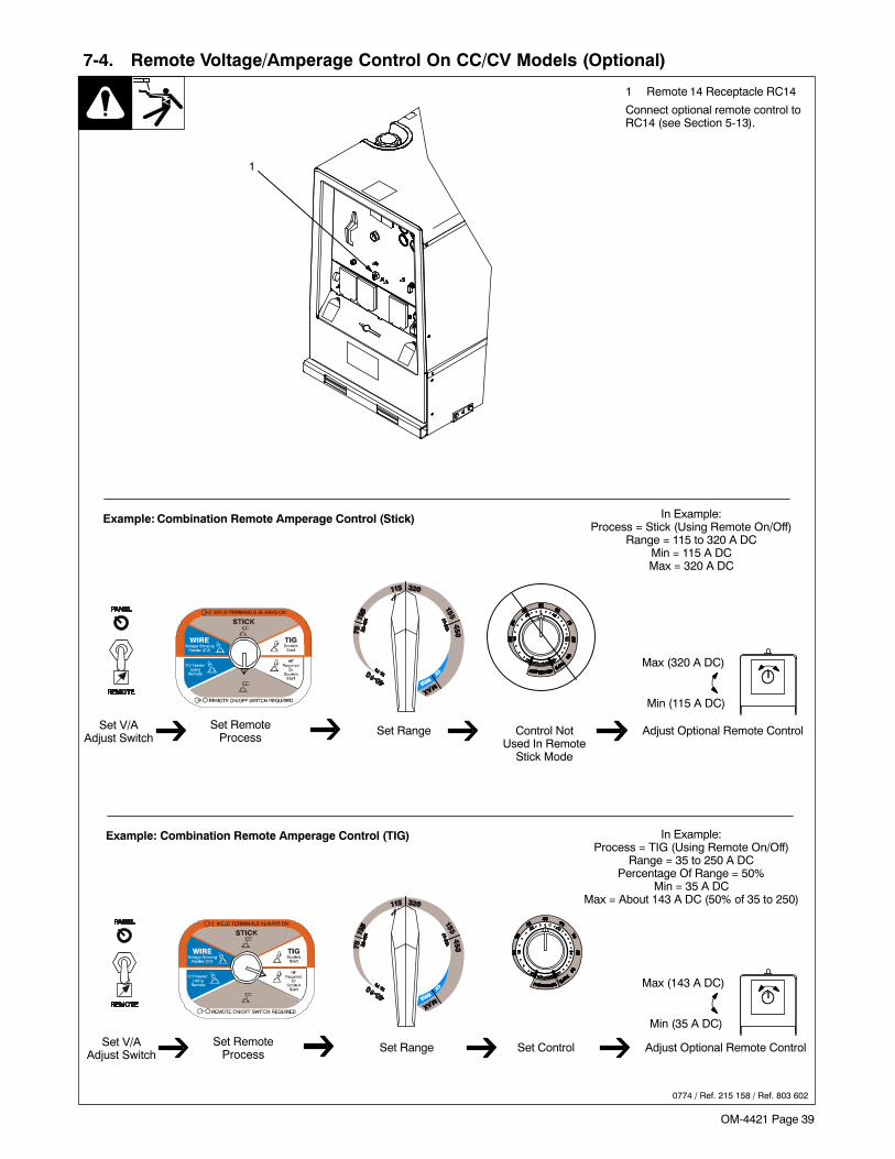
OM-4421 Page 39
7-4. Remote Voltage/Amperage Control On CC/CV Models (Optional)
1 Remote 14 Receptacle RC14
Connect optional remote control toRC14 (see Section 5-13).
0774 / Ref. 215 158 / Ref. 803 602
Example: Combination Remote Amperage Control (Stick)
Adjust Optional Remote ControlSet V/AAdjust Switch
Set Range Control NotUsed In Remote
Stick Mode
Set RemoteProcess
Example: Combination Remote Amperage Control (TIG)
Adjust Optional Remote ControlSet V/AAdjust Switch
Set Range Set ControlSet RemoteProcess
1
In Example:Process = Stick (Using Remote On/Off)
Range = 115 to 320 A DCMin = 115 A DCMax = 320 A DC
Max (320 A DC)
Min (115 A DC)
In Example:Process = TIG (Using Remote On/Off)
Range = 35 to 250 A DCPercentage Of Range = 50%
Min = 35 A DCMax = About 143 A DC (50% of 35 to 250)
Max (143 A DC)
Min (35 A DC)
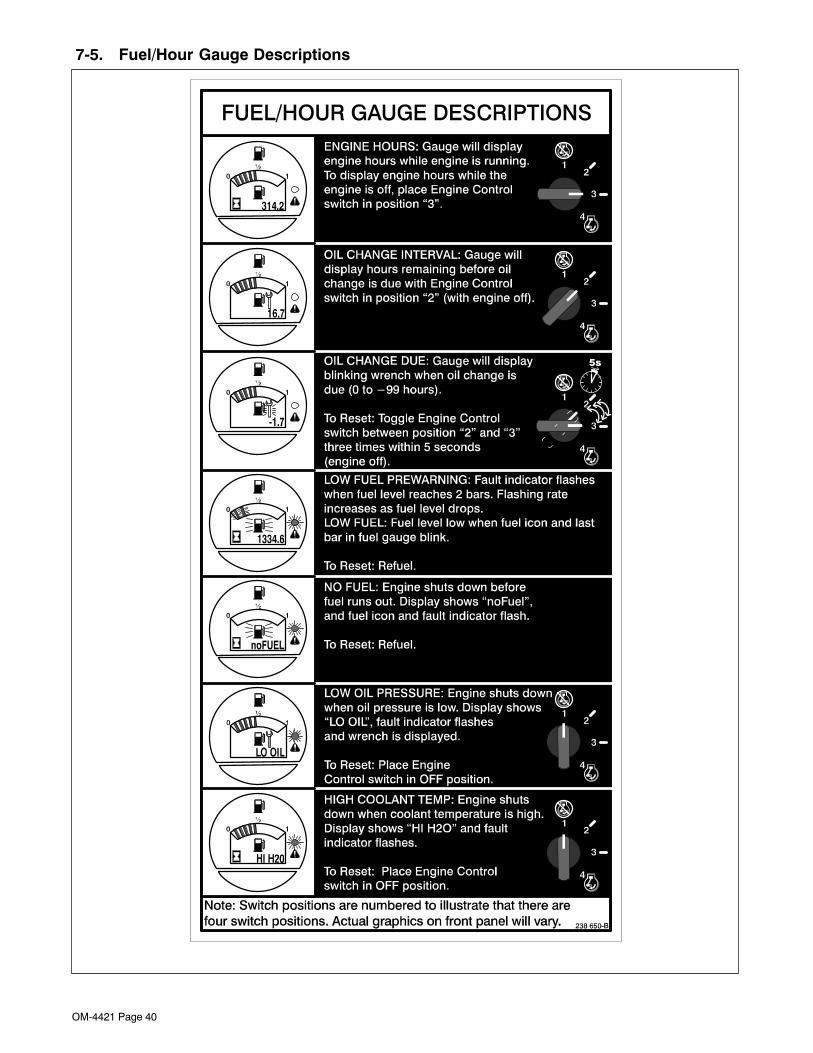
OM-4421 Page 40
7-5. Fuel/Hour Gauge Descriptions
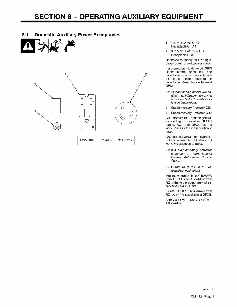
OM-4421 Page 41
SECTION 8 − OPERATING AUXILIARY EQUIPMENT
8-1. Domestic Auxiliary Power Receptacles
191 624-A
2
1 120 V 20 A AC GFCI Receptacle GFCI1
2 240 V 30 A AC TwistlockReceptacle RC1
Receptacles supply 60 Hz single-phase power at weld/power speed.
If a ground fault is detected, GFCIReset button pops out andreceptacle does not work. Checkfor faulty tools plugged inreceptacle. Press button to resetGFCI1.
� At least once a month, run en-gine at weld/power speed andpress test button to verify GFCIis working properly.
3 Supplementary Protector CB1
4 Supplementary Protector CB2
CB1 protects RC1 and the genera-tor winding from overload. If CB1opens, RC1 and GFCI1 do notwork. Place switch in On position toreset.
CB2 protects GFCI1 from overload.If CB2 opens, GFCI1 does notwork. Press button to reset.
� If a supplementary protectorcontinues to open, contactFactory Authorized ServiceAgent.
� Generator power is not af-fected by weld output.
Maximum output is 2.4 kVA/kWfrom GFCI1 and 4 kVA/kW fromRC1. Maximum output from all re-ceptacles is 4 kVA/kW.
EXAMPLE: If 13 A is drawn fromRC1, only 7 A is available at GFCI1:
(240 V x 13 A) + (120 V x 7 A) = 4.0 kVA/kW
1
3
4
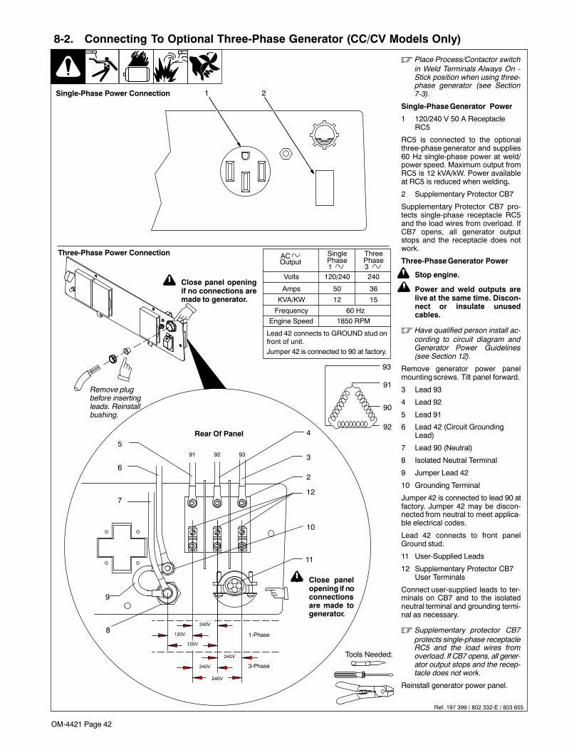
OM-4421 Page 42
8-2. Connecting To Optional Three-Phase Generator (CC/CV Models Only)
Ref. 197 399 / 802 332-E / 803 655
� Place Process/Contactor switchin Weld Terminals Always On -Stick position when using three-phase generator (see Section7-3).
Single-Phase Generator Power
1 120/240 V 50 A ReceptacleRC5
RC5 is connected to the optionalthree-phase generator and supplies60 Hz single-phase power at weld/power speed. Maximum output fromRC5 is 12 kVA/kW. Power availableat RC5 is reduced when welding.
2 Supplementary Protector CB7
Supplementary Protector CB7 pro-tects single-phase receptacle RC5and the load wires from overload. IfCB7 opens, all generator outputstops and the receptacle does notwork.
Three-Phase Generator Power
! Stop engine.
! Power and weld outputs arelive at the same time. Discon-nect or insulate unusedcables.
� Have qualified person install ac-cording to circuit diagram andGenerator Power Guidelines(see Section 12).
Remove generator power panelmounting screws. Tilt panel forward.
3 Lead 93
4 Lead 92
5 Lead 91
6 Lead 42 (Circuit GroundingLead)
7 Lead 90 (Neutral)
8 Isolated Neutral Terminal
9 Jumper Lead 42
10 Grounding Terminal
Jumper 42 is connected to lead 90 atfactory. Jumper 42 may be discon-nected from neutral to meet applica-ble electrical codes.
Lead 42 connects to front panelGround stud.
11 User-Supplied Leads
12 Supplementary Protector CB7User Terminals
Connect user-supplied leads to ter-minals on CB7 and to the isolatedneutral terminal and grounding termi-nal as necessary.
� Supplementary protector CB7protects single-phase receptacleRC5 and the load wires fromoverload. If CB7 opens, all gener-ator output stops and the recep-tacle does not work.
Reinstall generator power panel.
Tools Needed:
Volts
Amps
KVA/KW
Single
120/240
50
12
Three
240
36
15
60 HzFrequency
Engine Speed 1850 RPM
AC Phase1
Phase3
Output
Lead 42 connects to GROUND stud onfront of unit.Jumper 42 is connected to 90 at factory.
1 2
91 92 93
240V
120V
120V
240V
240V
1-Phase
3-Phase
3
4
5
6
7
8
9
10
11
12
Rear Of Panel
Three-Phase Power Connection
2
Single-Phase Power Connection
92
90
91
93
! Close panel openingif no connections aremade to generator.
! Close panelopening if noconnectionsare made togenerator.
240V
Remove plugbefore insertingleads. Reinstallbushing.
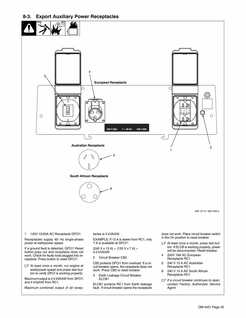
OM-4421 Page 43
8-3. Export Auxiliary Power Receptacles
1 120V 15/20A AC Receptacle GFCI1
Receptacles supply 60 Hz single-phasepower at weld/power speed.
If a ground fault is detected, GFCI1 Resetbutton pops out and receptacle does notwork. Check for faulty tools plugged into re-ceptacle. Press button to reset GFCI1.
� At least once a month, run engine atweld/power speed and press test but-ton to verify GFCI is working properly.
Maximum output is 2.4 kVA/kW from GFCI1and 4 kVa/kW from RC1.
Maximum combined output of all recep-
tacles is 4 kVA/kW.
EXAMPLE: If 13 A is drawn from RC1, only7 A is available at GFCI1:
(240 V x 13 A) + (120 V x 7 A) = 4.0 kVA/kW
2 Circuit Breaker CB2
CB2 protects GFCI1 from overload. If a cir-cuit breaker opens, the receptacle does notwork. Press CB2 to reset breaker.
3 Earth Leakage Circuit Breaker ELCB1
ELCB1 protects RC1 from Earth leakagefault. If circuit breaker opens the receptacle
does not work. Place circuit breaker switchin the On position to reset breaker.
� At least once a month, press test but-ton. If ELCB is working properly, powerwill be disconnected. Reset breaker.
4 220V 16A AC European Receptacle RC1
5 240 V 15 A AC AustralianReceptacle RC1
6 240 V 15 A AC South AfricanReceptacle RC1
� If a circuit breaker continues to open,contact Factory Authorized ServiceAgent.
4
2
3
1
European Receptacle
Australian Receptacle
South African Receptacle
5
6
238 127-A / 805 259-A
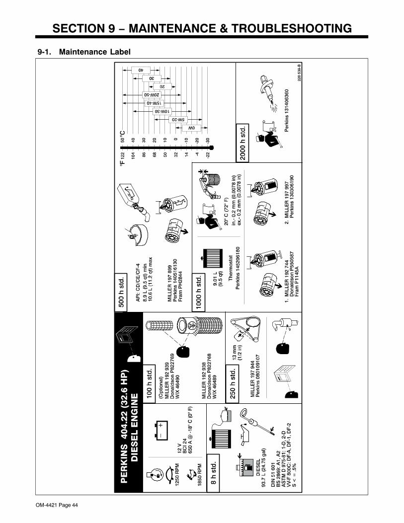
OM-4421 Page 44
SECTION 9 − MAINTENANCE & TROUBLESHOOTING
9-1. Maintenance Label
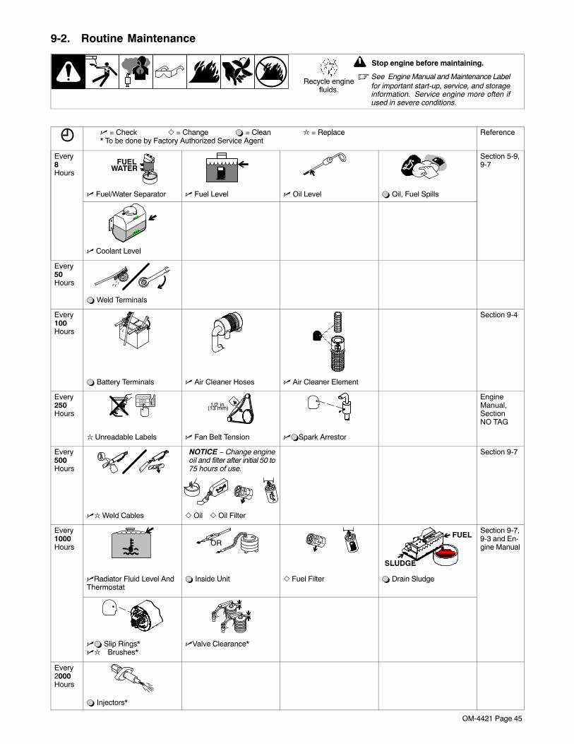
OM-4421 Page 45
9-2. Routine Maintenance
! Stop engine before maintaining.
� See Engine Manual and Maintenance Labelfor important start-up, service, and storageinformation. Service engine more often ifused in severe conditions.
Recycle enginefluids.
� = Check � = Change � = Clean = Replace* To be done by Factory Authorized Service Agent
Reference
Every8Hours
FUELWATER
Section 5-9,9-7
� Fuel/Water Separator � Fuel Level � Oil Level � Oil, Fuel Spills
� Coolant Level
Every50Hours
� Weld Terminals
Every100Hours
Section 9-4
� Battery Terminals � Air Cleaner Hoses � Air Cleaner Element
Every250Hours
1/2 in.(13 mm)
EngineManual,SectionNO TAG
Unreadable Labels � Fan Belt Tension ��Spark Arrestor
Every500Hours
NOTICE − Change engineoil and filter after initial 50 to75 hours of use.
Section 9-7
� Weld Cables � Oil � Oil Filter
Every1000Hours OR
SLUDGE
FUELSection 9-7,9-3 and En-gine Manual
�Radiator Fluid Level AndThermostat
� Inside Unit � Fuel Filter � Drain Sludge
�� Slip Rings*� Brushes*
�Valve Clearance*
Every2000Hours
� Injectors*
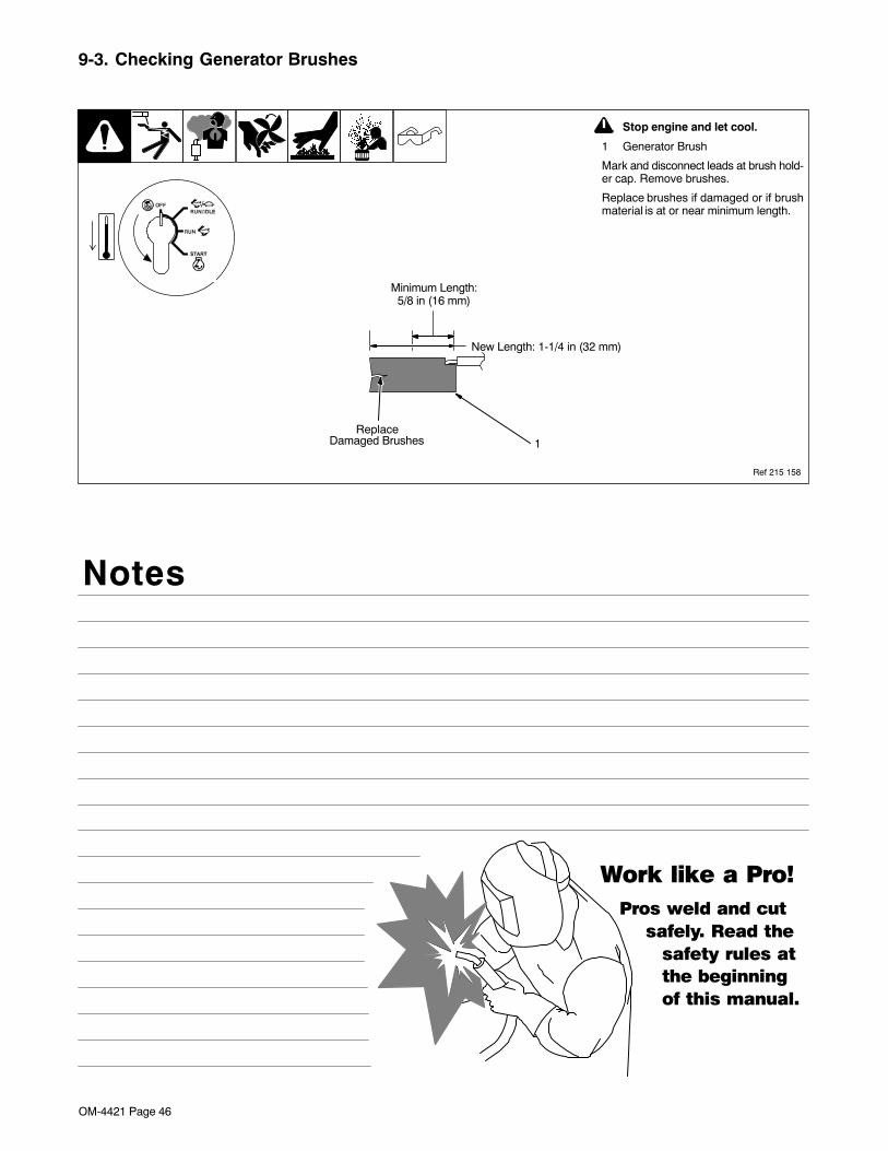
OM-4421 Page 46
9-3. Checking Generator Brushes
Ref 215 158
! Stop engine and let cool.
1 Generator Brush
Mark and disconnect leads at brush hold-er cap. Remove brushes.
Replace brushes if damaged or if brushmaterial is at or near minimum length.
1Damaged Brushes
New Length: 1-1/4 in (32 mm)
Minimum Length:5/8 in (16 mm)
Replace
Notes
Work like a Pro!
Pros weld and cut
safely. Read the
safety rules at
the beginning
of this manual.
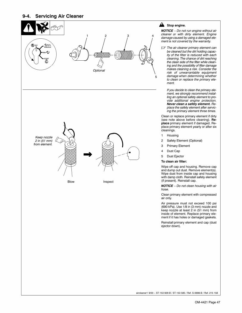
OM-4421 Page 47
9-4. Servicing Air Cleaner
! Stop engine.
NOTICE − Do not run engine without aircleaner or with dirty element. Enginedamage caused by using a damaged ele-ment is not covered by the warranty.
� The air cleaner primary element canbe cleaned but the dirt holding capac-ity of the filter is reduced with eachcleaning. The chance of dirt reachingthe clean side of the filter while clean-ing and the possibility of filter damagemakes cleaning a risk. Consider therisk of unwarrantable equipmentdamage when determining whetherto clean or replace the primary ele-ment.
If you decide to clean the primary ele-ment, we strongly recommend instal-ling an optional safety element to pro-vide additional engine protection.Never clean a safety element. Re-place the safety element after servic-ing the primary element three times.
Clean or replace primary element if dirty(see note above before cleaning). Re-place primary element if damaged. Re-place primary element yearly or after sixcleanings.
1 Housing
2 Safety Element (Optional)
3 Primary Element
4 Dust Cap
5 Dust Ejector
To clean air filter:
Wipe off cap and housing. Remove capand dump out dust. Remove element(s).Wipe dust from inside cap and housingwith damp cloth. Reinstall safety element(if present). Reinstall cap.
NOTICE − Do not clean housing with airhose.
Clean primary element with compressedair only.
Air pressure must not exceed 100 psi(690 kPa). Use 1/8 in (3 mm) nozzle andkeep nozzle at least 2 in (51 mm) frominside of element. Replace primary ele-ment if it has holes or damaged gaskets.
Reinstall primary element and cap (dustejector down).
Blow Inspect
41 3
5
Keep nozzle2 in (51 mm)
from element.
2
aircleaner1 9/00 − ST-153 929-B / ST-153 585 / Ref. S-0698-B / Ref. 215 158
Optional
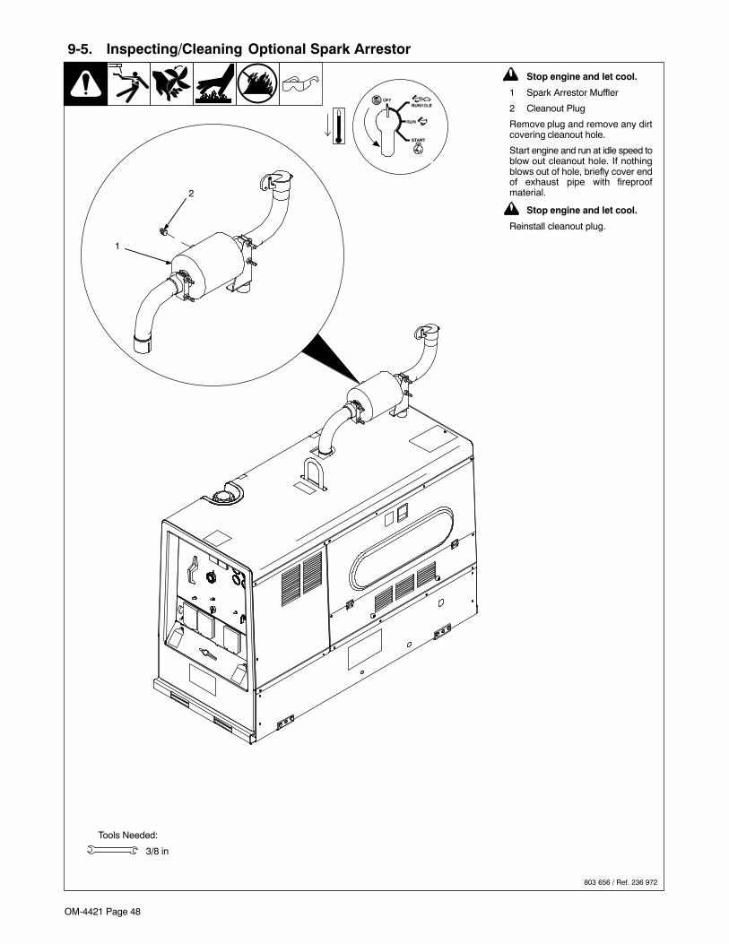
OM-4421 Page 48
9-5. Inspecting/Cleaning Optional Spark Arrestor
803 656 / Ref. 236 972
! Stop engine and let cool.
1 Spark Arrestor Muffler
2 Cleanout Plug
Remove plug and remove any dirtcovering cleanout hole.
Start engine and run at idle speed toblow out cleanout hole. If nothingblows out of hole, briefly cover endof exhaust pipe with fireproofmaterial.
! Stop engine and let cool.
Reinstall cleanout plug.
Tools Needed:
3/8 in
1
2
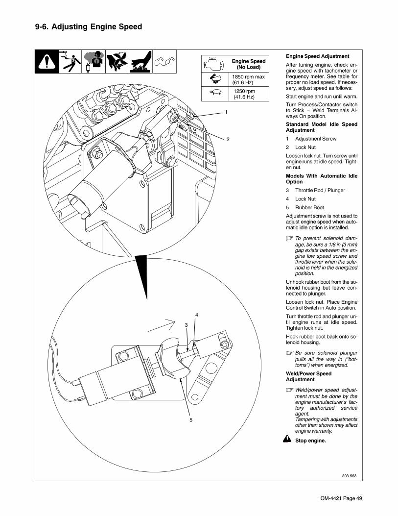
OM-4421 Page 49
9-6. Adjusting Engine Speed
803 563
Engine Speed Adjustment
After tuning engine, check en-gine speed with tachometer orfrequency meter. See table forproper no load speed. If neces-sary, adjust speed as follows:
Start engine and run until warm.
Turn Process/Contactor switchto Stick − Weld Terminals Al-ways On position.
Standard Model Idle SpeedAdjustment
1 Adjustment Screw
2 Lock Nut
Loosen lock nut. Turn screw untilengine runs at idle speed. Tight-en nut.
Models With Automatic IdleOption
3 Throttle Rod / Plunger
4 Lock Nut
5 Rubber Boot
Adjustment screw is not used toadjust engine speed when auto-matic idle option is installed.
� To prevent solenoid dam-age, be sure a 1/8 in (3 mm)gap exists between the en-gine low speed screw andthrottle lever when the sole-noid is held in the energizedposition.
Unhook rubber boot from the so-lenoid housing but leave con-nected to plunger.
Loosen lock nut. Place EngineControl Switch in Auto position.
Turn throttle rod and plunger un-til engine runs at idle speed.Tighten lock nut.
Hook rubber boot back onto so-lenoid housing.
� Be sure solenoid plungerpulls all the way in (“bot-toms”) when energized.
Weld/Power SpeedAdjustment
� Weld/power speed adjust-ment must be done by theengine manufacturer’s fac-tory authorized serviceagent.Tampering with adjustmentsother than shown may affectengine warranty.
! Stop engine.
1
2
3
4
5
1850 rpm max(61.6 Hz)
1250 rpm(41.6 Hz)
Engine Speed(No Load)
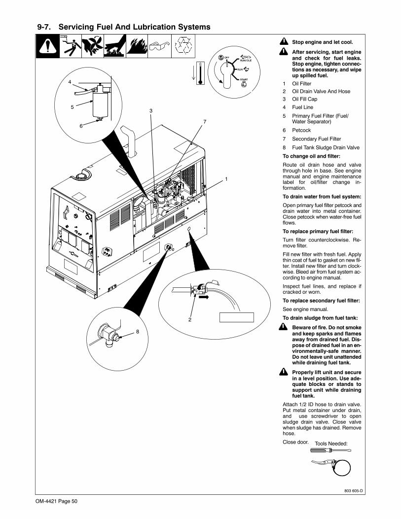
OM-4421 Page 50
9-7. Servicing Fuel And Lubrication Systems
803 605-D
! Stop engine and let cool.
! After servicing, start engineand check for fuel leaks.Stop engine, tighten connec-tions as necessary, and wipeup spilled fuel.
1 Oil Filter
2 Oil Drain Valve And Hose
3 Oil Fill Cap
4 Fuel Line
5 Primary Fuel Filter (Fuel/Water Separator)
6 Petcock
7 Secondary Fuel Filter
8 Fuel Tank Sludge Drain Valve
To change oil and filter:
Route oil drain hose and valvethrough hole in base. See enginemanual and engine maintenancelabel for oil/filter change in-formation.
To drain water from fuel system:
Open primary fuel filter petcock anddrain water into metal container.Close petcock when water-free fuelflows.
To replace primary fuel filter:
Turn filter counterclockwise. Re-move filter.
Fill new filter with fresh fuel. Applythin coat of fuel to gasket on new fil-ter. Install new filter and turn clock-wise. Bleed air from fuel system ac-cording to engine manual.
Inspect fuel lines, and replace ifcracked or worn.
To replace secondary fuel filter:
See engine manual.
To drain sludge from fuel tank:
! Beware of fire. Do not smokeand keep sparks and flamesaway from drained fuel. Dis-pose of drained fuel in an en-vironmentally-safe manner.Do not leave unit unattendedwhile draining fuel tank.
! Properly lift unit and securein a level position. Use ade-quate blocks or stands tosupport unit while drainingfuel tank.
Attach 1/2 ID hose to drain valve.Put metal container under drain,and use screwdriver to opensludge drain valve. Close valvewhen sludge has drained. Removehose.
Close door.
5
6
3
Tools Needed:
1
4
8
2
7
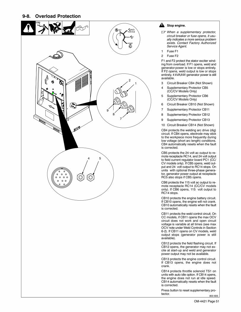
OM-4421 Page 51
9-8. Overload Protection
803 605
21
98
7
4
! Stop engine.
� When a supplementary protector,circuit breaker or fuse opens, it usu-ally indicates a more serious problemexists. Contact Factory AuthorizedService Agent.
1 Fuse F1
2 Fuse F2
F1 and F2 protect the stator exciter wind-ing from overload. If F1 opens, weld andgenerator power is low or stops entirely.If F2 opens, weld output is low or stopsentirely. 4 kVA/kW generator power is stillavailable.
3 Circuit Breaker CB4 (Not Shown)
4 Supplementary Protector CB5(CC/CV Models Only)
5 Supplementary Protector CB6(CC/CV Models Only)
6 Circuit Breaker CB10 (Not Shown)
7 Supplementary Protector CB11
8 Supplementary Protector CB12
9 Supplementary Protector CB13
10 Circuit Breaker CB14 (Not Shown)
CB4 protects the welding arc drive (dig)circuit. If CB4 opens, electrode may stickto the workpiece more frequently duringlow voltage (short arc length) conditions.CB4 automatically resets when the faultis corrected.
CB5 protects the 24 volt ac output to re-mote receptacle RC14, and 24 volt outputto field current regulator board PC1 (CC/CV models only). If CB5 opens, weld out-put and 24 volt output to RC14 stops. Onunits with optional three-phase genera-tor, generator power output at receptacleRC5 also stops if CB5 opens.
CB6 protects the 115 volt ac output to re-mote receptacle RC14 (CC/CV modelsonly). If CB6 opens, 115 volt output toRC14 stops.
CB10 protects the engine battery circuit.If CB10 opens, the engine will not crank.CB10 automatically resets when the faultis corrected.
CB11 protects the weld control circuit. OnCC models, if CB11 opens the max OCVcircuit does not work and open circuitvoltage is variable at all times (see maxOCV note under Weld Controls in Section6-2). If CB11 opens on CV models, weldoutput stops (generator power is stillavailable).
CB12 protects the field flashing circuit. IfCB12 opens, the generator may not ex-cite at start-up and weld and generatorpower output may not be available.
CB13 protects the engine control circuit.If CB13 opens, the engine does notcrank.
CB14 protects throttle solenoid TS1 onunits with auto idle option. If CB14 opens,the engine does not run at idle speed.CB14 automatically resets when the faultis corrected.
Press button to reset supplementary pro-tector.
5

OM-4421 Page 52
9-9. Troubleshooting
A. Welding − CC Models
Trouble Remedy
No weld output; generator power outputokay at ac receptacles.
Check position of Ampere Range switch.
Check position of optional Polarity switch.
Place Amperage Adjust switch in Panel position, or place switch in Remote position and connect remotecontrol to Remote Amperage Adjust receptacle RC13 (see Sections 5-12 and 6-1).
Check and secure connections to Remote Amperage Adjust receptacle RC13 (see Section 5-12).
Check fuse F2, and replace if open (see Section 9-8). Have Factory Authorized Service Agent check inte-grated rectifier SR2 and the rotor.
Have Factory Authorized Service Agent check brushes and slip rings, and weld excitation circuit.
No weld output or generator power out-put at ac receptacles.
Disconnect equipment from generator power receptacles during start-up.
Check fuses F1 and F2, and replace if open (see Section 9-8). Have Factory Authorized Service Agentcheck integrated rectifier SR1, capacitor C9, integrated rectifier SR2, and the rotor.
Reset supplementary protector CB12. Have Factory Authorized Service Agent check diode D1 (see Sec-tion 9-8).
Have Factory Authorized Service Agent check brushes and slip rings, and field excitation circuit.
Erratic weld output. Check and tighten connections inside and outside unit.
Be sure connection to work piece is clean and tight.
Use dry, properly stored electrodes.
Remove excessive coils from weld cables.
Have Factory Authorized Service Agent check brushes and slip rings.
High weld output. Check position of Ampere Range switch and Voltage/Amperage Adjust control.
Check engine speed, and have engine manufacturer’s factory authorized service agent adjust if neces-sary. See Section 9-6 for idle speed adjustment.
Have Factory Authorized Service Agent check OCV control circuit.
Low weld output. Check engine speed, and have engine manufacturer’s factory authorized service agent adjust if neces-sary. See Section 9-6 for idle speed adjustment.
Check fuses F1 and F2, and replace if open (see Section 9-8). Have Factory Authorized Service Agentcheck integrated rectifier SR1, capacitor C9, integrated rectifier SR2, and the rotor.
Electrode sticks to the workpiece morefrequently during low voltage (short arclength) conditions.
Circuit breaker CB4 may be open. CB4 automatically resets when the fault is corrected (see Section 9-8).Have Factory Authorized Service Agent check transformer T1 and integrated rectifiers SR4 and SR5.
Low open-circuit voltage. Check engine speed, and have engine manufacturer’s factory authorized service agent adjust if neces-sary. See Section 9-6 for idle speed adjustment.
Place Stick/TIG switch in Stick position.
Maximum weld output only in eachampere range (with Stick/TIG Selectionswitch in Stick position).
Have Factory Authorized Service Agent check control relay CR7.
No remote fine amperage control. Place Amperage Adjust switch in Remote position.
Check and secure connections to Remote Amperage Adjust receptacle RC13 (see Section 5-12).
Reset supplementary protector CB11 (see Section 9-8). Have Factory Authorized Service Agent checkcontrol relay CR7.
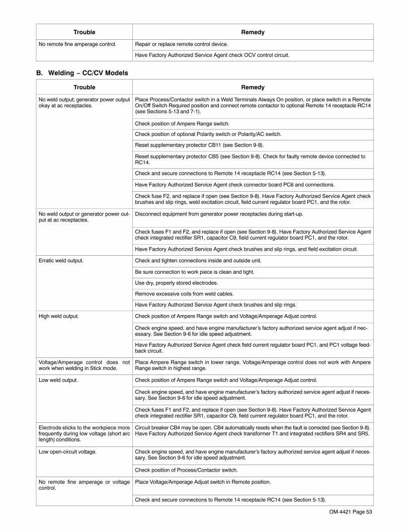
OM-4421 Page 53
Trouble Remedy
No remote fine amperage control. Repair or replace remote control device.
Have Factory Authorized Service Agent check OCV control circuit.
B. Welding − CC/CV Models
Trouble Remedy
No weld output; generator power outputokay at ac receptacles.
Place Process/Contactor switch in a Weld Terminals Always On position, or place switch in a RemoteOn/Off Switch Required position and connect remote contactor to optional Remote 14 receptacle RC14(see Sections 5-13 and 7-1).
Check position of Ampere Range switch.
Check position of optional Polarity switch or Polarity/AC switch.
Reset supplementary protector CB11 (see Section 9-8).
Reset supplementary protector CB5 (see Section 9-8). Check for faulty remote device connected toRC14.
Check and secure connections to Remote 14 receptacle RC14 (see Section 5-13).
Have Factory Authorized Service Agent check connector board PC6 and connections.
Check fuse F2, and replace if open (see Section 9-8). Have Factory Authorized Service Agent checkbrushes and slip rings, weld excitation circuit, field current regulator board PC1, and the rotor.
No weld output or generator power out-put at ac receptacles.
Disconnect equipment from generator power receptacles during start-up.
Check fuses F1 and F2, and replace if open (see Section 9-8). Have Factory Authorized Service Agentcheck integrated rectifier SR1, capacitor C9, field current regulator board PC1, and the rotor.
Have Factory Authorized Service Agent check brushes and slip rings, and field excitation circuit.
Erratic weld output. Check and tighten connections inside and outside unit.
Be sure connection to work piece is clean and tight.
Use dry, properly stored electrodes.
Remove excessive coils from weld cables.
Have Factory Authorized Service Agent check brushes and slip rings.
High weld output. Check position of Ampere Range switch and Voltage/Amperage Adjust control.
Check engine speed, and have engine manufacturer’s factory authorized service agent adjust if nec-essary. See Section 9-6 for idle speed adjustment.
Have Factory Authorized Service Agent check field current regulator board PC1, and PC1 voltage feed-back circuit.
Voltage/Amperage control does notwork when welding in Stick mode.
Place Ampere Range switch in lower range. Voltage/Amperage control does not work with AmpereRange switch in highest range.
Low weld output. Check position of Ampere Range switch and Voltage/Amperage Adjust control.
Check engine speed, and have engine manufacturer’s factory authorized service agent adjust if neces-sary. See Section 9-6 for idle speed adjustment.
Check fuses F1 and F2, and replace if open (see Section 9-8). Have Factory Authorized Service Agentcheck integrated rectifier SR1, capacitor C9, field current regulator board PC1, and the rotor.
Electrode sticks to the workpiece morefrequently during low voltage (short arclength) conditions.
Circuit breaker CB4 may be open. CB4 automatically resets when the fault is corrected (see Section 9-8).Have Factory Authorized Service Agent check transformer T1 and integrated rectifiers SR4 and SR5.
Low open-circuit voltage. Check engine speed, and have engine manufacturer’s factory authorized service agent adjust if neces-sary. See Section 9-6 for idle speed adjustment.
Check position of Process/Contactor switch.
No remote fine amperage or voltagecontrol.
Place Voltage/Amperage Adjust switch in Remote position.
Check and secure connections to Remote 14 receptacle RC14 (see Section 5-13).
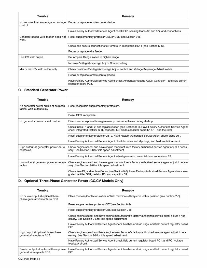
OM-4421 Page 54
Trouble Remedy
No remote fine amperage or voltagecontrol.
Repair or replace remote control device.
Have Factory Authorized Service Agent check PC1 sensing leads (36 and 37), and connections.
Constant speed wire feeder does notwork.
Reset supplementary protector CB5 or CB6 (see Section 9-8).
Check and secure connections to Remote 14 receptacle RC14 (see Section 5-13).
Repair or replace wire feeder.
Low CV weld output. Set Ampere Range switch to highest range.
Increase Voltage/Amperage Adjust Control setting.
Min or max CV weld output only. Check position of Voltage/Amperage Adjust control and Voltage/Amperage Adjust switch.
Repair or replace remote control device.
Have Factory Authorized Service Agent check Amperage/Voltage Adjust Control R1, and field currentregulator board PC1.
C. Standard Generator Power
Trouble Remedy
No generator power output at ac recep-tacles; weld output okay.
Reset receptacle supplementary protectors.
Reset GFCI receptacle.
No generator power or weld output. Disconnect equipment from generator power receptacles during start-up.
Check fuses F1 and F2, and replace if open (see Section 9-8). Have Factory Authorized Service Agentcheck integrated rectifier SR1, capacitor C9, diode/capacitor board D1/C1, and the rotor.
Reset supplementary protector CB12. Have Factory Authorized Service Agent check diode D1 .
Have Factory Authorized Service Agent check brushes and slip rings, and field excitation circuit.
High output at generator power ac re-ceptacles.
Check engine speed, and have engine manufacturer’s factory authorized service agent adjust if neces-sary. See Section 9-6 for idle speed adjustment.
Have Factory Authorized Service Agent adjust generator power field current resistor R3.
Low output at generator power ac recep-tacles.
Check engine speed, and have engine manufacturer’s factory authorized service agent adjust if neces-sary. See Section 9-6 for idle speed adjustment.
Check fuse F1, and replace if open (see Section 9-8). Have Factory Authorized Service Agent check inte-grated rectifier SR1, resistor R3, and capacitor C9.
D. Optional Three-Phase Generator Power (CC/CV Models Only)
Trouble Remedy
No or low output at optional three-phase generator/receptacle RC5.
Place Process/Contactor switch in Weld Terminals Always On - Stick position (see Section 7-3).
Reset supplementary protector CB7(see Section 8-2).
Reset supplementary protector CB5 (see Section 9-8).
Check engine speed, and have engine manufacturer’s factory authorized service agent adjust if nec-essary. See Section 9-6 for idle speed adjustment.
Have Factory Authorized Service Agent check brushes and slip rings, and field current regulator boardPC1.
High output at optional three-phasegenerator/receptacle RC5.
Check engine speed, and have engine manufacturer’s factory authorized service agent adjust if nec-essary. See Section 9-6 for idle speed adjustment.
Have Factory Authorized Service Agent check field current regulator board PC1, and PC1 voltagefeedback circuit.
Erratic output at optional three-phasegenerator/receptacle RC5.
Have Factory Authorized Service Agent check brushes and slip rings, and field current regulator boardPC1.

OM-4421 Page 55
E. Engine
Trouble Remedy
Engine will not crank. Check battery, and replace if necessary.
Check battery connections and tighten if necessary.
Circuit breaker CB10 may be open. CB10 automatically resets when fault is corrected (see Section 9-8).Have Factory Authorized Service Agent check engine wiring harness and components.
Check engine wiring harness plug connections.
Have Factory Authorized Service Agent check control relay CR1 and Engine Control switch S1.
Engine cranks but does not start. Check fuel level.
Check battery and replace if necessary. Check engine charging system according to engine manual.
Have Factory Authorized Service Agent check engine wiring harness, fuel gauge/hourmeter, controlrelay CR5, fuel pump, fuel solenoid FS1, and diode/capacitor board D10/C10.
Air in fuel system. See engine manual.
Engine starts, but stops when EngineControl switch is released.
Check oil, and coolant levels. Automatic shutdown system stops engine if oil pressure is too low or coolanttemperature is too high (see Section 5-9). Automatic shutdown system is inhibited for 30 seconds afterstart-up.
Have Factory Authorized Service Agent check fuel gauge/hourmeter, and control relay CR5.
Engine hard to start in cold weather. Use starting aid switch (see Section 6-1 or 7-1).
Keep battery in good condition. Store battery in warm area off cold surface.
Use fuel formulated for cold weather (diesel fuel can gel in cold weather). Contact local fuel supplier forfuel information.
Use correct grade oil for cold weather (see Section 9-1).
Engine suddenly stops. Check oil and coolant levels. Automatic shutdown system stops engine if oil pressure is too low or coolanttemperature is too high (see Section 5-9). Automatic shutdown system is inhibited for 30 seconds afterstart-up.
See engine manual.
Engine slowly stopped and cannot berestarted.
Check fuel level.
Check engine air and fuel filters (see Sections 9-4 and 9-7).
See engine manual.
Battery discharges between uses. Turn Engine Control switch off when unit is not running.
Clean top of battery with baking soda and water solution; rinse with clear water.
Recharge or replace battery if necessary.
Periodically recharge battery (approximately every 3 months).
Engine idles, but does not come up toweld speed (models with idle optiononly).
Have Factory Authorized Service Agent check idle module PC7 and current transformer CT1.
Check for obstructed throttle solenoid.
Engine does not run at idle speed(models with idle option only).
CC models: place Stick/TIG Selection switch in Stick position.CC/CV models: place Process/Contactor switch in any position but Remote On/Off Switch Required-TIG.
Check for obstructed throttle solenoid.
Have Factory Authorized Service Agent check idle module PC7, and control relays CR3 and CR6.
Engine uses oil during run-in period;wetstacking occurs.
Dry engine according to run-in procedure (see Section 11).
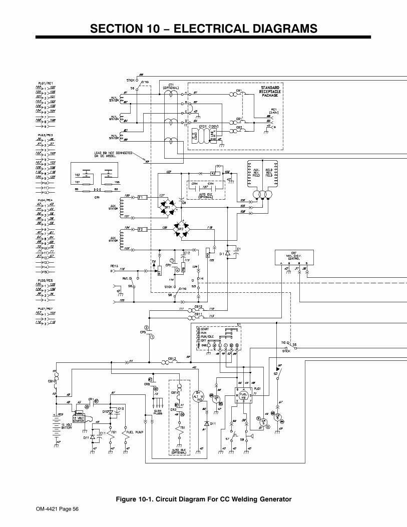
OM-4421 Page 56
SECTION 10 − ELECTRICAL DIAGRAMS
Figure 10-1. Circuit Diagram For CC Welding Generator
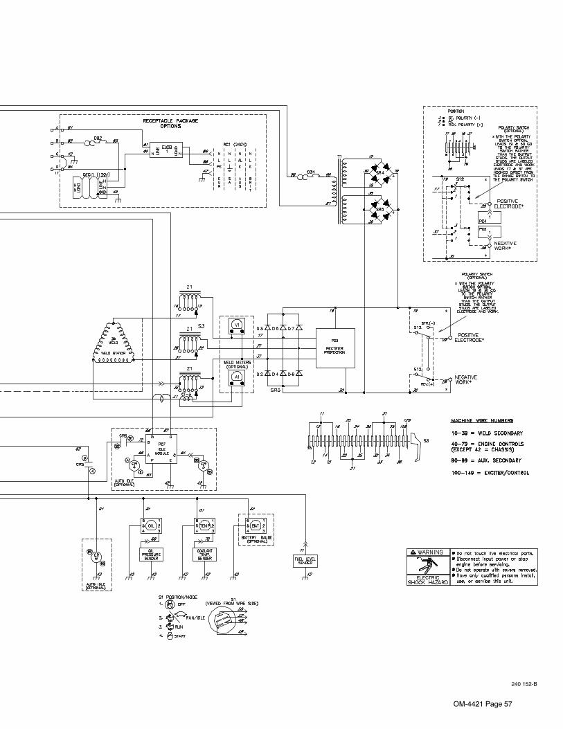
OM-4421 Page 57
240 152-B
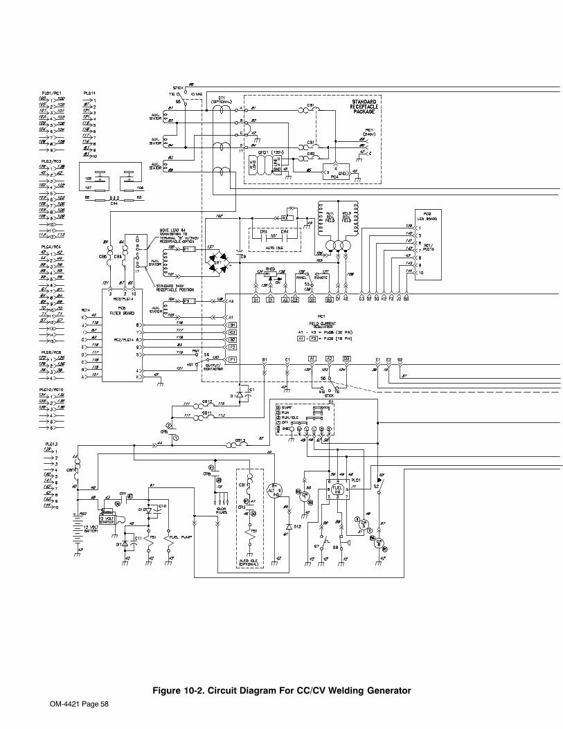
OM-4421 Page 58
Figure 10-2. Circuit Diagram For CC/CV Welding Generator
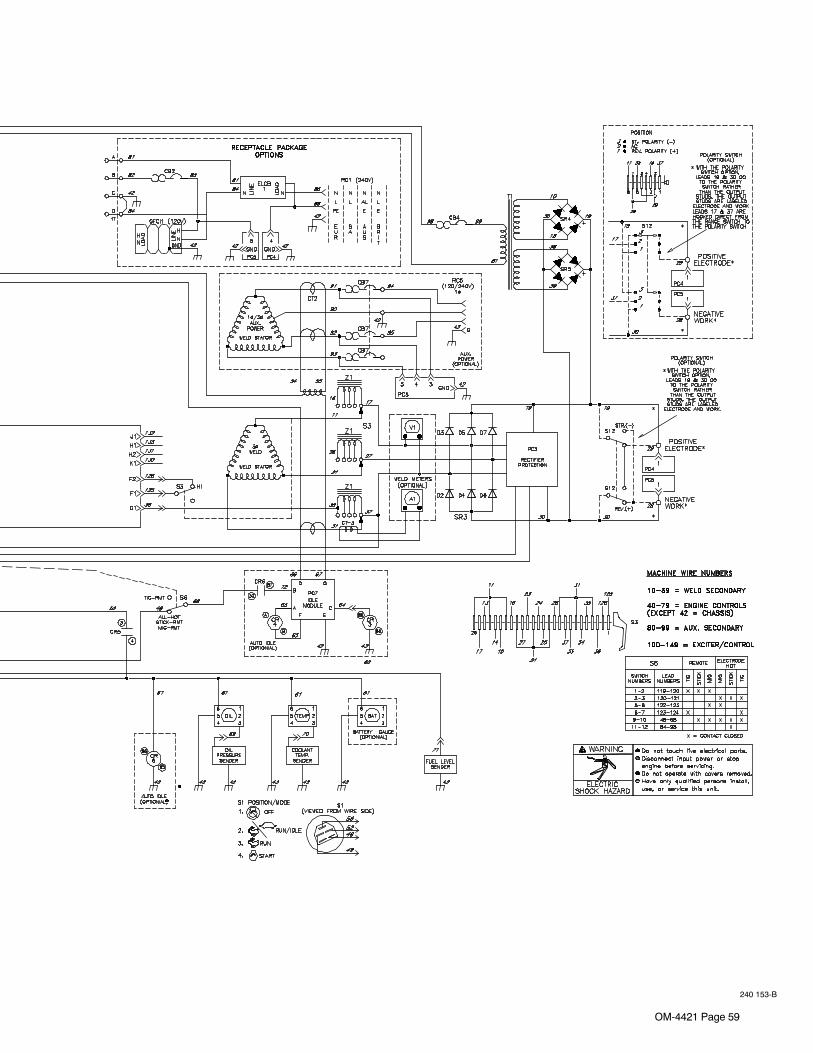
OM-4421 Page 59
240 153-B
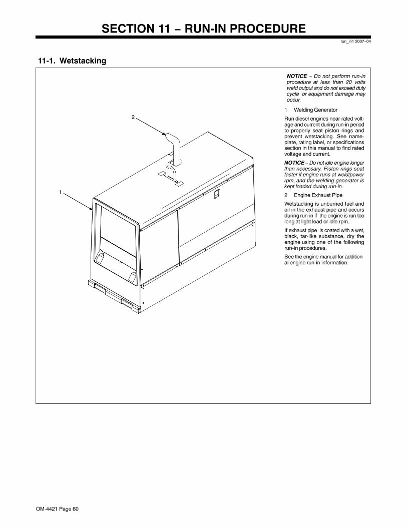
OM-4421 Page 60
SECTION 11 − RUN-IN PROCEDURErun_in1 2007−04
11-1. Wetstacking
1 Welding Generator
Run diesel engines near rated volt-age and current during run-in periodto properly seat piston rings andprevent wetstacking. See name-plate, rating label, or specificationssection in this manual to find ratedvoltage and current.
NOTICE − Do not idle engine longerthan necessary. Piston rings seatfaster if engine runs at weld/powerrpm, and the welding generator iskept loaded during run-in.
2 Engine Exhaust Pipe
Wetstacking is unburned fuel andoil in the exhaust pipe and occursduring run-in if the engine is run toolong at light load or idle rpm.
If exhaust pipe is coated with a wet,black, tar-like substance, dry theengine using one of the followingrun-in procedures.
See the engine manual for addition-al engine run-in information.
2
1
NOTICE − Do not perform run-inprocedure at less than 20 voltsweld output and do not exceed dutycycle or equipment damage mayoccur.
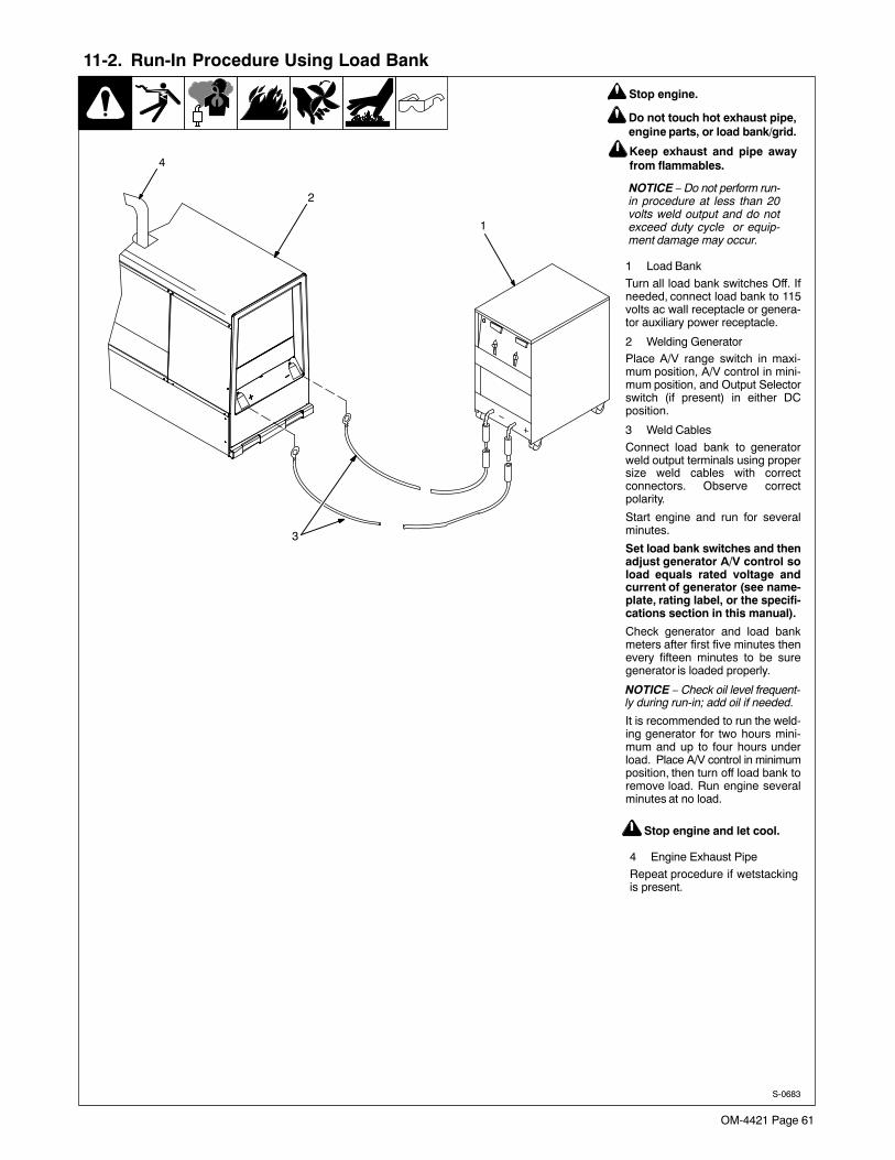
OM-4421 Page 61
11-2. Run-In Procedure Using Load Bank
S-0683
1 Load Bank
Turn all load bank switches Off. Ifneeded, connect load bank to 115volts ac wall receptacle or genera-tor auxiliary power receptacle.
2 Welding GeneratorPlace A/V range switch in maxi-mum position, A/V control in mini-mum position, and Output Selectorswitch (if present) in either DCposition.
3 Weld Cables
Connect load bank to generatorweld output terminals using propersize weld cables with correctconnectors. Observe correctpolarity.
Start engine and run for severalminutes.
Set load bank switches and thenadjust generator A/V control soload equals rated voltage andcurrent of generator (see name-plate, rating label, or the specifi-cations section in this manual).
Check generator and load bankmeters after first five minutes thenevery fifteen minutes to be suregenerator is loaded properly.
NOTICE − Check oil level frequent-ly during run-in; add oil if needed.
It is recommended to run the weld-ing generator for two hours mini-mum and up to four hours underload. Place A/V control in minimumposition, then turn off load bank toremove load. Run engine severalminutes at no load.
2
3
1
4
Stop engine.
Do not touch hot exhaust pipe,engine parts, or load bank/grid.
Keep exhaust and pipe awayfrom flammables.
NOTICE − Do not perform run-in procedure at less than 20volts weld output and do notexceed duty cycle or equip-ment damage may occur.
Stop engine and let cool.
4 Engine Exhaust Pipe
Repeat procedure if wetstackingis present.
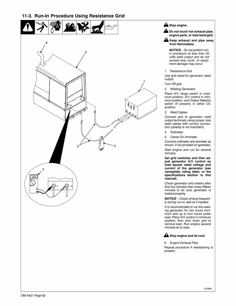
OM-4421 Page 62
11-3. Run-In Procedure Using Resistance Grid
S-0684
1 Resistance Grid
Use grid sized for generator ratedoutput.
Turn Off grid.
2 Welding Generator
Place A/V range switch in maxi-mum position, A/V control in mini-mum position, and Output Selectorswitch (if present) in either DCposition.
3 Weld Cables
Connect grid to generator weldoutput terminals using proper sizeweld cables with correct connec-tors (polarity is not important).
4 Voltmeter
5 Clamp-On Ammeter
Connect voltmeter and ammeter asshown, if not provided on generator.
Start engine and run for severalminutes.
Set grid switches and then ad-just generator A/V control soload equals rated voltage andcurrent of the generator (seenameplate, rating label, or thespecifications section in thismanual).
Check generator and meters afterfirst five minutes then every fifteenminutes to be sure generator isloaded properly.
NOTICE − Check oil level frequent-ly during run-in; add oil if needed.
It is recommended to run the weld-ing generator for two hours mini-mum and up to four hours underload. Place A/V control in minimumposition, then shut down grid toremove load. Run engine severalminutes at no load.
1
3 5
+
4
2
6
Stop engine.
Do not touch hot exhaust pipe,engine parts, or load bank/grid.
Keep exhaust and pipe awayfrom flammables.
NOTICE − Do not perform run-in procedure at less than 20volts weld output and do notexceed duty cycle or equip-ment damage may occur.
Stop engine and let cool.
6 Engine Exhaust Pipe
Repeat procedure if wetstacking ispresent.
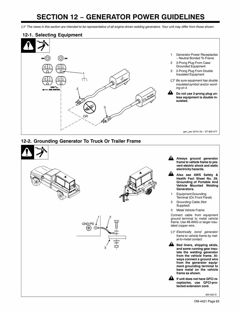
OM-4421 Page 63
SECTION 12 − GENERATOR POWER GUIDELINES� The views in this section are intended to be representative of all engine-driven welding generators. Your unit may differ from those shown.
12-1. Selecting Equipment
gen_pwr 2010−04 − ST-800 577
1 Generator Power Receptacles− Neutral Bonded To Frame
2 3-Prong Plug From CaseGrounded Equipment
3 2-Prong Plug From DoubleInsulated Equipment
� Be sure equipment has doubleinsulated symbol and/or word-ing on it.
! Do not use 2-prong plug un-less equipment is double in-sulated.
OR
2
3
1
! Always ground generatorframe to vehicle frame to pre-vent electric shock and staticelectricity hazards.
! Also see AWS Safety &Health Fact Sheet No. 29,Grounding of Portable AndVehicle Mounted WeldingGenerators.
1 Equipment GroundingTerminal (On Front Panel)
2 Grounding Cable (NotSupplied)
3 Metal Vehicle Frame
Connect cable from equipmentground terminal to metal vehicleframe. Use #8 AWG or larger insu-lated copper wire.
� Electrically bond generatorframe to vehicle frame by met-al-to-metal contact.
! Bed liners, shipping skids,and some running gear insu-late the welding generatorfrom the vehicle frame. Al-ways connect a ground wirefrom the generator equip-ment grounding terminal tobare metal on the vehicleframe as shown.
! If unit does not have GFCI re-ceptacles, use GFCI-pro-tected extension cord.
12-2. Grounding Generator To Truck Or Trailer Frame
800 652-D
1
3
2
GND/PE
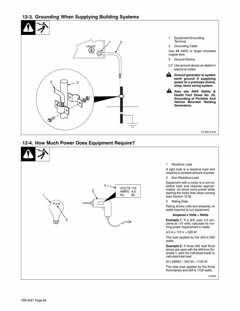
OM-4421 Page 64
12-3. Grounding When Supplying Building Systems
ST-800 576-B
1 Equipment GroundingTerminal
2 Grounding Cable
Use #8 AWG or larger insulatedcopper wire.
3 Ground Device
� Use ground device as stated inelectrical codes.
! Ground generator to systemearth ground if supplyingpower to a premises (home,shop, farm) wiring system.
! Also see AWS Safety &Health Fact Sheet No. 29,Grounding of Portable AndVehicle Mounted WeldingGenerators.
GND/PE
1 2
2 3
12-4. How Much Power Does Equipment Require?
S-0623
1 Resistive Load
A light bulb is a resistive load andrequires a constant amount of power.
2 Non-Resistive Load
Equipment with a motor is a non-re-sistive load and requires approxi-mately six times more power whilestarting the motor than when running(see Section 12-8).
3 Rating Data
Rating shows volts and amperes, orwatts required to run equipment.
Amperes x Volts = Watts
Example 1: If a drill uses 4.5 am-peres at 115 volts, calculate its run-ning power requirement in watts.
4.5 A x 115 V = 520 W
The load applied by the drill is 520watts.
Example 2: If three 200 watt floodlamps are used with the drill from Ex-ample 1, add the individual loads tocalculate total load.
(3 x 200W) + 520 W = 1120 W
The total load applied by the threeflood lamps and drill is 1120 watts.
VOLTS 1154.560
AMPSHz1
2
3
3

OM-4421 Page 65
12-5. Approximate Power Requirements For Industrial Motors
Industrial Motors Rating Starting Watts Running Watts
Split Phase 1/8 HP 800 300
1/6 HP 1225 500
1/4 HP 1600 600
1/3 HP 2100 700
1/2 HP 3175 875
Capacitor Start-Induction Run 1/3 HP 2020 720
1/2 HP 3075 975
3/4 HP 4500 1400
1 HP 6100 1600
1-1/2 HP 8200 2200
2 HP 10550 2850
3 HP 15900 3900
5 HP 23300 6800
Capacitor Start-Capacitor Run 1-1/2 HP 8100 2000
5 HP 23300 6000
7-1/2 HP 35000 8000
10 HP 46700 10700
Fan Duty 1/8 HP 1000 400
1/6 HP 1400 550
1/4 HP 1850 650
1/3 HP 2400 800
1/2 HP 3500 1100
12-6. Approximate Power Requirements For Farm/Home Equipment
Farm/Home Equipment Rating Starting Watts Running Watts
Stock Tank De-Icer 1000 1000
Grain Cleaner 1/4 HP 1650 650
Portable Conveyor 1/2 HP 3400 1000
Grain Elevator 3/4 HP 4400 1400
Milk Cooler 2900 1100
Milker (Vacuum Pump) 2 HP 10500 2800
FARM DUTY MOTORS 1/3 HP 1720 720
Std. (e.g. Conveyors, 1/2 HP 2575 975
Feed Augers, Air 3/4 HP 4500 1400
Compressors) 1 HP 6100 1600
1-1/2 HP 8200 2200
2 HP 10550 2850
3 HP 15900 3900
5 HP 23300 6800
High Torque (e.g. Barn 1-1/2 HP 8100 2000
Cleaners, Silo Unloaders, 5 HP 23300 6000
Silo Hoists, Bunk Feeders) 7-1/2 HP 35000 8000
10 HP 46700 10700
3-1/2 cu. ft. Mixer 1/2 HP 3300 1000
High Pressure 1.8 Gal/Min 500 PSI 3150 950
Washer 2 gal/min 550 PSI 4500 1400
2 gal/min 700 PSI 6100 1600
Refrigerator or Freezer 3100 800
Shallow Well Pump 1/3 HP 2150 750
1/2 HP 3100 1000
Sump Pump 1/3 HP 2100 800
1/2 HP 3200 1050

OM-4421 Page 66
12-7. Approximate Power Requirements For Contractor EquipmentContractor Rating Starting Watts Running Watts
Hand Drill 1/4 in 350 350
3/8 in 400 400
1/2 in 600 600
Circular Saw 6-1/2 in 500 500
7-1/4 in 900 900
8-1/4 in 1400 1400
Table Saw 9 in 4500 1500
10 in 6300 1800
Band Saw 14 in 2500 1100
Bench Grinder 6 in 1720 720
8 in 3900 1400
10 in 5200 1600
Air Compressor 1/2 HP 3000 1000
1 HP 6000 1500
1-1/2 HP 8200 2200
2 HP 10500 2800
Electric Chain Saw 1-1/2 HP, 12 in 1100 1100
2 HP, 14 in 1100 1100
Electric Trimmer Standard 9 in 350 350
Heavy Duty 12 in 500 500
Electric Cultivator 1/3 HP 2100 700
Elec. Hedge Trimmer 18 in 400 400
Flood Lights HID 125 100
Metal Halide 313 250
Mercury 1000
Sodium 1400
Vapor 1250 1000
Submersible Pump 400 gph 600 200
Centrifugal Pump 900 gph 900 500
Floor Polisher 3/4 HP, 16 in 4500 1400
1 HP, 20 in 6100 1600
High Pressure Washer 1/2 HP 3150 950
3/4 HP 4500 1400
1 HP 6100 1600
55 gal Drum Mixer 1/4 HP 1900 700
Wet & Dry Vac 1.7 HP 900 900
2-1/2 HP 1300 1300
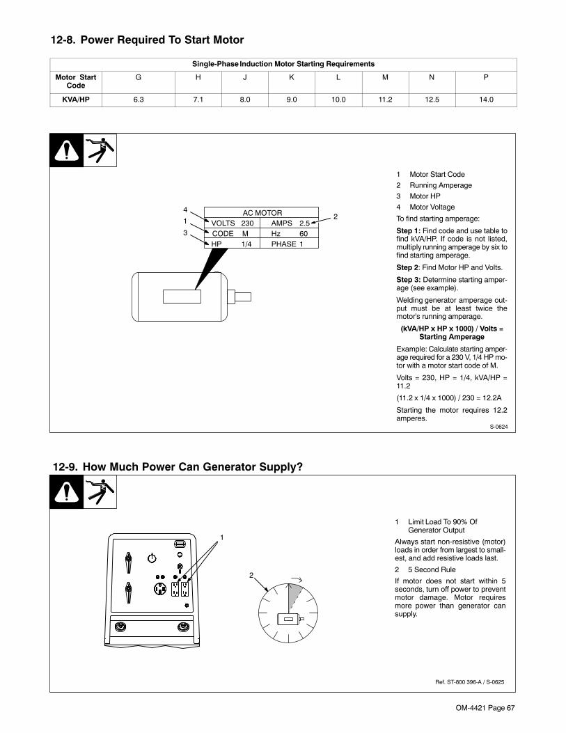
OM-4421 Page 67
12-8. Power Required To Start Motor
Single-Phase Induction Motor Starting Requirements
Motor StartCode
G H J K L M N P
KVA/HP 6.3 7.1 8.0 9.0 10.0 11.2 12.5 14.0
S-0624
1 Motor Start Code
2 Running Amperage
3 Motor HP
4 Motor Voltage
To find starting amperage:
Step 1: Find code and use table tofind kVA/HP. If code is not listed,multiply running amperage by six tofind starting amperage.
Step 2: Find Motor HP and Volts.
Step 3: Determine starting amper-age (see example).
Welding generator amperage out-put must be at least twice themotor’s running amperage.
(kVA/HP x HP x 1000) / Volts =Starting Amperage
Example: Calculate starting amper-age required for a 230 V, 1/4 HP mo-tor with a motor start code of M.
Volts = 230, HP = 1/4, kVA/HP =11.2
(11.2 x 1/4 x 1000) / 230 = 12.2A
Starting the motor requires 12.2amperes.
VOLTS AMPS
HP
230 2.5
1/4HzPHASE
CODE 601
M
AC MOTOR1
2
3
4
12-9. How Much Power Can Generator Supply?
Ref. ST-800 396-A / S-0625
1 Limit Load To 90% OfGenerator Output
Always start non-resistive (motor)loads in order from largest to small-est, and add resistive loads last.
2 5 Second Rule
If motor does not start within 5seconds, turn off power to preventmotor damage. Motor requiresmore power than generator cansupply.
1
2
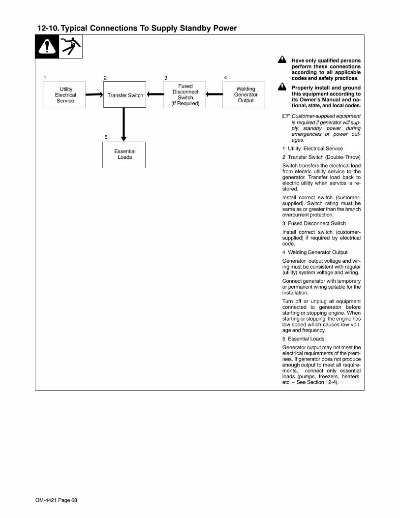
OM-4421 Page 68
12-10. Typical Connections To Supply Standby Power
Transfer Switch
EssentialLoads
FusedDisconnect
Switch(If Required)
UtilityElectricalService
1 2 3 4
5
WeldingGenerator
Output
! Have only qualified personsperform these connectionsaccording to all applicablecodes and safety practices.
! Properly install and groundthis equipment according toits Owner’s Manual and na-tional, state, and local codes.
� Customer-supplied equipmentis required if generator will sup-ply standby power duringemergencies or power out-ages.
1 Utility Electrical Service
2 Transfer Switch (Double-Throw)
Switch transfers the electrical loadfrom electric utility service to thegenerator. Transfer load back toelectric utility when service is re-stored.
Install correct switch (customer-supplied). Switch rating must besame as or greater than the branchovercurrent protection.
3 Fused Disconnect Switch
Install correct switch (customer-supplied) if required by electricalcode.
4 Welding Generator Output
Generator output voltage and wir-ing must be consistent with regular(utility) system voltage and wiring.
Connect generator with temporaryor permanent wiring suitable for theinstallation.
Turn off or unplug all equipmentconnected to generator beforestarting or stopping engine. Whenstarting or stopping, the engine haslow speed which causes low volt-age and frequency.
5 Essential Loads
Generator output may not meet theelectrical requirements of the prem-ises. If generator does not produceenough output to meet all require-ments, connect only essentialloads (pumps, freezers, heaters,etc. − See Section 12-4).
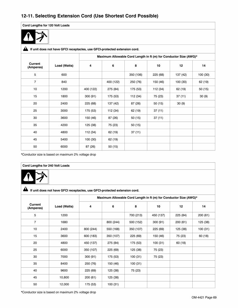
OM-4421 Page 69
12-11. Selecting Extension Cord (Use Shortest Cord Possible)
Cord Lengths for 120 Volt Loads
If unit does not have GFCI receptacles, use GFCI-protected extension cord.
Maximum Allowable Cord Length in ft (m) for Conductor Size (AWG)*
Current (Amperes) Load (Watts) 4 6 8 10 12 14
5 600 350 (106) 225 (68) 137 (42) 100 (30)
7 840 400 (122) 250 (76) 150 (46) 100 (30) 62 (19)
10 1200 400 (122) 275 (84) 175 (53) 112 (34) 62 (19) 50 (15)
15 1800 300 (91) 175 (53) 112 (34) 75 (23) 37 (11) 30 (9)
20 2400 225 (68) 137 (42) 87 (26) 50 (15) 30 (9)
25 3000 175 (53) 112 (34) 62 (19) 37 (11)
30 3600 150 (46) 87 (26) 50 (15) 37 (11)
35 4200 125 (38) 75 (23) 50 (15)
40 4800 112 (34) 62 (19) 37 (11)
45 5400 100 (30) 62 (19)
50 6000 87 (26) 50 (15)
*Conductor size is based on maximum 2% voltage drop
Cord Lengths for 240 Volt Loads
If unit does not have GFCI receptacles, use GFCI-protected extension cord.
Maximum Allowable Cord Length in ft (m) for Conductor Size (AWG)*
Current(Amperes) Load (Watts) 4 6 8 10 12 14
5 1200 700 (213) 450 (137) 225 (84) 200 (61)
7 1680 800 (244) 500 (152) 300 (91) 200 (61) 125 (38)
10 2400 800 (244) 550 (168) 350 (107) 225 (69) 125 (38) 100 (31)
15 3600 600 (183) 350 (107) 225 (69) 150 (46) 75 (23) 60 (18)
20 4800 450 (137) 275 (84) 175 (53) 100 (31) 60 (18)
25 6000 350 (107) 225 (69) 125 (38) 75 (23)
30 7000 300 (91) 175 (53) 100 (31) 75 (23)
35 8400 250 (76) 150 (46) 100 (31)
40 9600 225 (69) 125 (38) 75 (23)
45 10,800 200 (61) 125 (38)
50 12,000 175 (53) 100 (31)
*Conductor size is based on maximum 2% voltage drop
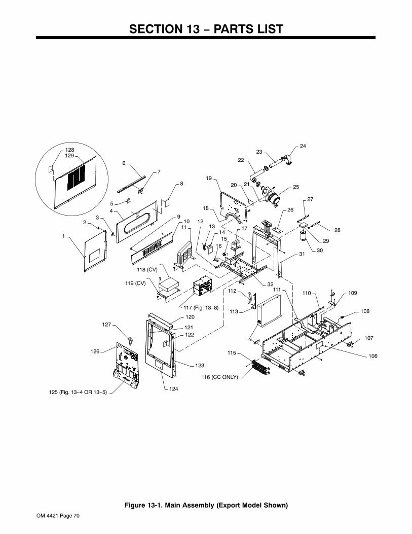
OM-4421 Page 70
SECTION 13 − PARTS LIST
1
23
45
6
7
8
910
11 131415
12
16
17
18
1920 21
22
2324
25
26
27
28
29
3031
32
106
107
108
109110111112
113
115
116 (CC ONLY)
117 (Fig. 13−8)
118 (CV)
119 (CV)
120
121122
123
124125 (Fig. 13−4 OR 13−5)
126
127
128129
Figure 13-1. Main Assembly (Export Model Shown)
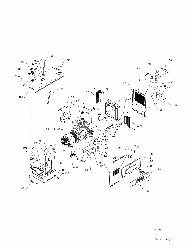
OM-4421 Page 71
803 646-J
33
34
35
36
3738
3940
41
42
4344
45
46
4748
49
5051
52
53
54
55
5657
58
59
6162
6364
6566
676869707172
7374
7576
7778 79
808182
83
85
84
8687
88
8990
91
93 (Fig. 13−7)
9596
97
9899
100
101102
103
104
105 94
128
92
60
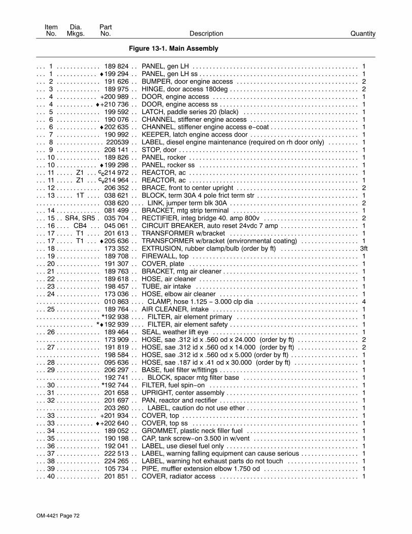
OM-4421 Page 72
DescriptionPartNo.
Dia.Mkgs.
ItemNo.
Figure 13-1. Main Assembly
Quantity
1 189 824 PANEL, gen LH 1. . . . . . . . . . . . . . . . . . . . . . . . . . . . . . . . . . . . . . . . . . . . . . . . . . . . . . . . . . . . . . . . . . .1 ♦199 294 PANEL, gen LH ss 1. . . . . . . . . . . . . . . . . . . . . . . . . . . . . . . . . . . . . . . . . . . . . . . . . . . . . . . . . . . . . . . .2 191 626 BUMPER, door engine access 2. . . . . . . . . . . . . . . . . . . . . . . . . . . . . . . . . . . . . . . . . . . . . . . . . . . . . .3 189 975 HINGE, door access 180deg 2. . . . . . . . . . . . . . . . . . . . . . . . . . . . . . . . . . . . . . . . . . . . . . . . . . . . . . . .4 +200 989 DOOR, engine access 1. . . . . . . . . . . . . . . . . . . . . . . . . . . . . . . . . . . . . . . . . . . . . . . . . . . . . . . . . . . .4 ♦+210 736 DOOR, engine access ss 1. . . . . . . . . . . . . . . . . . . . . . . . . . . . . . . . . . . . . . . . . . . . . . . . . . . . . . . . .5 199 592 LATCH, paddle series 20 (black) 1. . . . . . . . . . . . . . . . . . . . . . . . . . . . . . . . . . . . . . . . . . . . . . . . . . . .6 190 076 CHANNEL, stiffener engine access 1. . . . . . . . . . . . . . . . . . . . . . . . . . . . . . . . . . . . . . . . . . . . . . . . . .6 ♦202 635 CHANNEL, stiffener engine access e−coat 1. . . . . . . . . . . . . . . . . . . . . . . . . . . . . . . . . . . . . . . . . . .7 190 992 KEEPER, latch engine access door 1. . . . . . . . . . . . . . . . . . . . . . . . . . . . . . . . . . . . . . . . . . . . . . . . . .8 220539 LABEL, diesel engine maintenance (required on rh door only) 1. . . . . . . . . . . . . . . . . . . . . . . . . . . .9 208 141 STOP, door 1. . . . . . . . . . . . . . . . . . . . . . . . . . . . . . . . . . . . . . . . . . . . . . . . . . . . . . . . . . . . . . . . . . . . . . .
10 189 826 PANEL, rocker 1. . . . . . . . . . . . . . . . . . . . . . . . . . . . . . . . . . . . . . . . . . . . . . . . . . . . . . . . . . . . . . . . . . . .10 ♦199 298 PANEL, rocker ss 1. . . . . . . . . . . . . . . . . . . . . . . . . . . . . . . . . . . . . . . . . . . . . . . . . . . . . . . . . . . . . . . .11 Z1 CC214 972 REACTOR, ac 1. . . . . . . . . . . . . . . . . . . . . . . . . . . . . . . . . . . . . . . . . . . . . . . . . . . . . . . . . . . . . . .11 Z1 CV214 964 REACTOR, ac 1. . . . . . . . . . . . . . . . . . . . . . . . . . . . . . . . . . . . . . . . . . . . . . . . . . . . . . . . . . . . . . .12 206 352 BRACE, front to center upright 2. . . . . . . . . . . . . . . . . . . . . . . . . . . . . . . . . . . . . . . . . . . . . . . . . . . . . .13 1T 038 621 BLOCK, term 30A 4 pole frict term str 1. . . . . . . . . . . . . . . . . . . . . . . . . . . . . . . . . . . . . . . . . . . .
038 620 LINK, jumper term blk 30A 2. . . . . . . . . . . . . . . . . . . . . . . . . . . . . . . . . . . . . . . . . . . . . . . . . . . . . . . . . . . . .14 081 499 BRACKET, mtg strip terminal 1. . . . . . . . . . . . . . . . . . . . . . . . . . . . . . . . . . . . . . . . . . . . . . . . . . . . . . .15 SR4, SR5 035 704 RECTIFIER, integ bridge 40. amp 800v 2. . . . . . . . . . . . . . . . . . . . . . . . . . . . . . . . . . . .16 CB4 045 061 CIRCUIT BREAKER, auto reset 24vdc 7 amp 1. . . . . . . . . . . . . . . . . . . . . . . . . . . . . . . . . . .17 T1 201 613 TRANSFORMER w/bracket 1. . . . . . . . . . . . . . . . . . . . . . . . . . . . . . . . . . . . . . . . . . . . . . . . . . . .17 T1 ♦205 636 TRANSFORMER w/bracket (environmental coating) 1. . . . . . . . . . . . . . . . . . . . . . . . . . . . . .18 173 352 EXTRUSION, rubber clamp/bulb (order by ft) 3ft. . . . . . . . . . . . . . . . . . . . . . . . . . . . . . . . . . . . . . . . .19 189 708 FIREWALL, top 1. . . . . . . . . . . . . . . . . . . . . . . . . . . . . . . . . . . . . . . . . . . . . . . . . . . . . . . . . . . . . . . . . . .20 191 307 COVER, plate 1. . . . . . . . . . . . . . . . . . . . . . . . . . . . . . . . . . . . . . . . . . . . . . . . . . . . . . . . . . . . . . . . . . . .21 189 763 BRACKET, mtg air cleaner 1. . . . . . . . . . . . . . . . . . . . . . . . . . . . . . . . . . . . . . . . . . . . . . . . . . . . . . . . . .22 189 618 HOSE, air cleaner 1. . . . . . . . . . . . . . . . . . . . . . . . . . . . . . . . . . . . . . . . . . . . . . . . . . . . . . . . . . . . . . . . .23 198 457 TUBE, air intake 1. . . . . . . . . . . . . . . . . . . . . . . . . . . . . . . . . . . . . . . . . . . . . . . . . . . . . . . . . . . . . . . . . .24 173 036 HOSE, elbow air cleaner 1. . . . . . . . . . . . . . . . . . . . . . . . . . . . . . . . . . . . . . . . . . . . . . . . . . . . . . . . . . .
010 863 CLAMP, hose 1.125 − 3.000 clp dia 4. . . . . . . . . . . . . . . . . . . . . . . . . . . . . . . . . . . . . . . . . . . . . . . . . . . . .25 189 764 AIR CLEANER, intake 1. . . . . . . . . . . . . . . . . . . . . . . . . . . . . . . . . . . . . . . . . . . . . . . . . . . . . . . . . . . . .
*192 938 FILTER, air element primary 1. . . . . . . . . . . . . . . . . . . . . . . . . . . . . . . . . . . . . . . . . . . . . . . . . . . . . . . . . . .*♦192 939 FILTER, air element safety 1. . . . . . . . . . . . . . . . . . . . . . . . . . . . . . . . . . . . . . . . . . . . . . . . . . . . . . . . . . .
26 189 464 SEAL, weather lift eye 1. . . . . . . . . . . . . . . . . . . . . . . . . . . . . . . . . . . . . . . . . . . . . . . . . . . . . . . . . . . . .173 909 HOSE, sae .312 id x .560 od x 24.000 (order by ft) 2. . . . . . . . . . . . . . . . . . . . . . . . . . . . . . . . . . . . . . .
27 191 819 HOSE, sae .312 id x .560 od x 14.000 (order by ft) 2. . . . . . . . . . . . . . . . . . . . . . . . . . . . . . . . . . . .198 584 HOSE, sae .312 id x .560 od x 5.000 (order by ft) 1. . . . . . . . . . . . . . . . . . . . . . . . . . . . . . . . . . . . . . . . .
28 095 636 HOSE, sae .187 id x .41 od x 30.000 (order by ft) 1. . . . . . . . . . . . . . . . . . . . . . . . . . . . . . . . . . . . .29 206 297 BASE, fuel filter w/fittings 1. . . . . . . . . . . . . . . . . . . . . . . . . . . . . . . . . . . . . . . . . . . . . . . . . . . . . . . . . . .
192 741 BLOCK, spacer mtg filter base 1. . . . . . . . . . . . . . . . . . . . . . . . . . . . . . . . . . . . . . . . . . . . . . . . . . . . . . . . .30 *192 744 FILTER, fuel spin−on 1. . . . . . . . . . . . . . . . . . . . . . . . . . . . . . . . . . . . . . . . . . . . . . . . . . . . . . . . . . . . . .31 201 658 UPRIGHT, center assembly 1. . . . . . . . . . . . . . . . . . . . . . . . . . . . . . . . . . . . . . . . . . . . . . . . . . . . . . . . .32 201 697 PAN, reactor and rectifier 1. . . . . . . . . . . . . . . . . . . . . . . . . . . . . . . . . . . . . . . . . . . . . . . . . . . . . . . . . . .
203 260 LABEL, caution do not use ether 1. . . . . . . . . . . . . . . . . . . . . . . . . . . . . . . . . . . . . . . . . . . . . . . . . . . . . . . .33 +201 934 COVER, top 1. . . . . . . . . . . . . . . . . . . . . . . . . . . . . . . . . . . . . . . . . . . . . . . . . . . . . . . . . . . . . . . . . . . . .33 ♦+202 640 COVER, top ss 1. . . . . . . . . . . . . . . . . . . . . . . . . . . . . . . . . . . . . . . . . . . . . . . . . . . . . . . . . . . . . . . . .34 189 052 GROMMET, plastic neck filler fuel 1. . . . . . . . . . . . . . . . . . . . . . . . . . . . . . . . . . . . . . . . . . . . . . . . . . .35 190 198 CAP, tank screw−on 3.500 in w/vent 1. . . . . . . . . . . . . . . . . . . . . . . . . . . . . . . . . . . . . . . . . . . . . . . . .36 192 041 LABEL, use diesel fuel only 1. . . . . . . . . . . . . . . . . . . . . . . . . . . . . . . . . . . . . . . . . . . . . . . . . . . . . . . . .37 222 513 LABEL, warning falling equipment can cause serious 1. . . . . . . . . . . . . . . . . . . . . . . . . . . . . . . . . . .38 224 265 LABEL, warning hot exhaust parts do not touch 1. . . . . . . . . . . . . . . . . . . . . . . . . . . . . . . . . . . . . . .39 105 734 PIPE, muffler extension elbow 1.750 od 1. . . . . . . . . . . . . . . . . . . . . . . . . . . . . . . . . . . . . . . . . . . . . .40 201 851 COVER, radiator access 1. . . . . . . . . . . . . . . . . . . . . . . . . . . . . . . . . . . . . . . . . . . . . . . . . . . . . . . . . . .
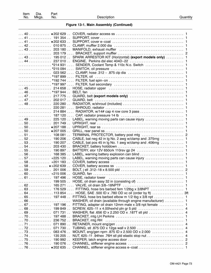
OM-4421 Page 73
DescriptionPartNo.
Dia.Mkgs.
ItemNo.
Figure 13-1. Main Assembly (Continued)
Quantity
40 ♦202 629 COVER, radiator access ss 1. . . . . . . . . . . . . . . . . . . . . . . . . . . . . . . . . . . . . . . . . . . . . . . . . . . . . . . .41 191 354 SUPPORT, cover 1. . . . . . . . . . . . . . . . . . . . . . . . . . . . . . . . . . . . . . . . . . . . . . . . . . . . . . . . . . . . . . . . . .41 ♦202 633 SUPPORT, cover e−coat 1. . . . . . . . . . . . . . . . . . . . . . . . . . . . . . . . . . . . . . . . . . . . . . . . . . . . . . . . . .42 010 875 CLAMP, muffler 2.000 dia 1. . . . . . . . . . . . . . . . . . . . . . . . . . . . . . . . . . . . . . . . . . . . . . . . . . . . . . . . . .43 203 180 MANIFOLD, exhaust muffler 1. . . . . . . . . . . . . . . . . . . . . . . . . . . . . . . . . . . . . . . . . . . . . . . . . . . . . . .
203 179 BRACKET, support muffler 2. . . . . . . . . . . . . . . . . . . . . . . . . . . . . . . . . . . . . . . . . . . . . . . . . . . . . . . . . . . . .43 195 012 SPARK ARRESTOR KIT (Horizontal) (export models only) 1. . . . . . . . . . . . . . . . . . . . . . . . . . . .44 237 010 ENGINE, Perkins dsl elec 404D−22 1. . . . . . . . . . . . . . . . . . . . . . . . . . . . . . . . . . . . . . . . . . . . . . . . .
*214 931 SENDER, Coolant Temp & 110c N.o. Switch 1. . . . . . . . . . . . . . . . . . . . . . . . . . . . . . . . . . . . . . . . . . . . .*215 094 SWITCH, oil pressure 1. . . . . . . . . . . . . . . . . . . . . . . . . . . . . . . . . . . . . . . . . . . . . . . . . . . . . . . . . . . . . . . . .023 562 CLAMP, hose .312 − .875 clp dia 1. . . . . . . . . . . . . . . . . . . . . . . . . . . . . . . . . . . . . . . . . . . . . . . . . . . . . . .
*197 899 FILTER, oil 1. . . . . . . . . . . . . . . . . . . . . . . . . . . . . . . . . . . . . . . . . . . . . . . . . . . . . . . . . . . . . . . . . . . . . . . . . .*192 744 FILTER, fuel spin−on 1. . . . . . . . . . . . . . . . . . . . . . . . . . . . . . . . . . . . . . . . . . . . . . . . . . . . . . . . . . . . . . . . . .*197 997 FILTER, fuel secondary 1. . . . . . . . . . . . . . . . . . . . . . . . . . . . . . . . . . . . . . . . . . . . . . . . . . . . . . . . . . . . . . .
45 214 658 HOSE, radiator upper 1. . . . . . . . . . . . . . . . . . . . . . . . . . . . . . . . . . . . . . . . . . . . . . . . . . . . . . . . . . . . .46 *197 944 BELT, fan 1. . . . . . . . . . . . . . . . . . . . . . . . . . . . . . . . . . . . . . . . . . . . . . . . . . . . . . . . . . . . . . . . . . . . . . . .47 217 775 GUARD, belt (export models only) 1. . . . . . . . . . . . . . . . . . . . . . . . . . . . . . . . . . . . . . . . . . . . . . . . .47 202 017 GUARD, belt 1. . . . . . . . . . . . . . . . . . . . . . . . . . . . . . . . . . . . . . . . . . . . . . . . . . . . . . . . . . . . . . . . . . . . .48 220 280 RADIATOR, w/shroud (includes) 1. . . . . . . . . . . . . . . . . . . . . . . . . . . . . . . . . . . . . . . . . . . . . . . . . . . . .
220 281 SHROUD, radiator 1. . . . . . . . . . . . . . . . . . . . . . . . . . . . . . . . . . . . . . . . . . . . . . . . . . . . . . . . . . . . . . . . . . . .214 884 RADIATOR, w/14# cap 4 row core 3 pass 1. . . . . . . . . . . . . . . . . . . . . . . . . . . . . . . . . . . . . . . . . . . . . . . .187 120 CAP, radiator pressure 14 lb 1. . . . . . . . . . . . . . . . . . . . . . . . . . . . . . . . . . . . . . . . . . . . . . . . . . . . . . . . . . .
49 225 120 LABEL, warning moving parts can cause injury 1. . . . . . . . . . . . . . . . . . . . . . . . . . . . . . . . . . . . . . . .50 201 749 UPRIGHT, rear 1. . . . . . . . . . . . . . . . . . . . . . . . . . . . . . . . . . . . . . . . . . . . . . . . . . . . . . . . . . . . . . . . . . . .50 ♦207 188 UPRIGHT, rear ss 1. . . . . . . . . . . . . . . . . . . . . . . . . . . . . . . . . . . . . . . . . . . . . . . . . . . . . . . . . . . . . . . .50 ♦207 005 GRILL, rear panel ss 1. . . . . . . . . . . . . . . . . . . . . . . . . . . . . . . . . . . . . . . . . . . . . . . . . . . . . . . . . . . . . .51 108 081 TERMINAL PROTECTOR, battery post mtg 2. . . . . . . . . . . . . . . . . . . . . . . . . . . . . . . . . . . . . . . . . .52 190 206 CABLE, bat neg 42 in lg No. 2 awg w/clamp and .375rng 1. . . . . . . . . . . . . . . . . . . . . . . . . . . . . . .53 190 207 CABLE, bat pos 45 in lg No. 1 awg w/clamp and .406rng 1. . . . . . . . . . . . . . . . . . . . . . . . . . . . . . .54 203 430 BRACKET, battery holddown 1. . . . . . . . . . . . . . . . . . . . . . . . . . . . . . . . . . . . . . . . . . . . . . . . . . . . . . . .55 190 897 BATTERY, stor 12V 650crk 110rsv gp 24 1. . . . . . . . . . . . . . . . . . . . . . . . . . . . . . . . . . . . . . . . . . . . .56 168 385 LABEL, warning battery explosion can blind 1. . . . . . . . . . . . . . . . . . . . . . . . . . . . . . . . . . . . . . . . . . .57 +225 120 LABEL, warning moving parts can cause injury 1. . . . . . . . . . . . . . . . . . . . . . . . . . . . . . . . . . . . . . .58 +201 183 COVER, battery access 1. . . . . . . . . . . . . . . . . . . . . . . . . . . . . . . . . . . . . . . . . . . . . . . . . . . . . . . . . . .58 ♦+202 639 COVER, battery access ss 1. . . . . . . . . . . . . . . . . . . . . . . . . . . . . . . . . . . . . . . . . . . . . . . . . . . . . . .59 201 006 BOLT, j stl .312−18 x 8.500 pld 2. . . . . . . . . . . . . . . . . . . . . . . . . . . . . . . . . . . . . . . . . . . . . . . . . . . . . .60 +215 006 GUARD, fan 1. . . . . . . . . . . . . . . . . . . . . . . . . . . . . . . . . . . . . . . . . . . . . . . . . . . . . . . . . . . . . . . . . . . . .61 197 496 HOSE, radiator lower 1. . . . . . . . . . . . . . . . . . . . . . . . . . . . . . . . . . . . . . . . . . . . . . . . . . . . . . . . . . . . .
199 505 HOSE, oil drain assy 32 in (consisting of) 1. . . . . . . . . . . . . . . . . . . . . . . . . . . . . . . . . . . . . . . . . . . . . . . .62 165 271 VALVE, oil drain 3/8−18NPTF 1. . . . . . . . . . . . . . . . . . . . . . . . . . . . . . . . . . . . . . . . . . . . . . . . . . . . . . .63 176 529 FITTING, hose brs barbed fem 1/2tbg x 3/8NPT 1. . . . . . . . . . . . . . . . . . . . . . . . . . . . . . . . . . . . . . .64 113 854 HOSE, SAE .500 ID x .780 OD xc oil (order by ft) 3ft. . . . . . . . . . . . . . . . . . . . . . . . . . . . . . . . . . . . . . .65 197 448 FITTING, hose brs barbed elbow m 1/2 tbg x 3/8 npt 1. . . . . . . . . . . . . . . . . . . . . . . . . . . . . . . . . . .66 WASHER, oil drain (available through engine manufacturer) 1. . . . . . . . . . . . . . . . . . . . . . . . . . . . . . . . . . . . . .67 197 196 FITTING, adapter oil drain 12mm male x 3/8 npt female 1. . . . . . . . . . . . . . . . . . . . . . . . . . . . . . . .68 199 849 SCREW, 625−11 x 4.00hexhd pln gr 5 pld 4. . . . . . . . . . . . . . . . . . . . . . . . . . . . . . . . . . . . . . . . . . . .69 071 731 WASHER, flat .656 ID x 2.250 OD x .187T stl pld 4. . . . . . . . . . . . . . . . . . . . . . . . . . . . . . . . . . . . . .70 197 488 BRACKET, mtg LH Perkins 1. . . . . . . . . . . . . . . . . . . . . . . . . . . . . . . . . . . . . . . . . . . . . . . . . . . . . . . . .70 236 752 BRACKET, mtg RH 1. . . . . . . . . . . . . . . . . . . . . . . . . . . . . . . . . . . . . . . . . . . . . . . . . . . . . . . . . . . . . . .71 071 890 RETAINER, mount eng/gen 4. . . . . . . . . . . . . . . . . . . . . . . . . . . . . . . . . . . . . . . . . . . . . . . . . . . . . . . . .72 071 730 TUBING, stl .875 OD x 12ga wall x 2.500 4. . . . . . . . . . . . . . . . . . . . . . . . . . . . . . . . . . . . . . . . . . . . .73 083 476 MOUNT, eng/gen nprn .875 ID x 2.500 OD x 2.000 4. . . . . . . . . . . . . . . . . . . . . . . . . . . . . . . . . . . .74 135 205 NUT, 625−11 .94hex .76H stl pld elastic stop nut 4. . . . . . . . . . . . . . . . . . . . . . . . . . . . . . . . . . . . . . .75 190 992 KEEPER, latch engine access door 2. . . . . . . . . . . . . . . . . . . . . . . . . . . . . . . . . . . . . . . . . . . . . . . . . .76 190 076 CHANNEL, stiffener engine access 2. . . . . . . . . . . . . . . . . . . . . . . . . . . . . . . . . . . . . . . . . . . . . . . . . .76 ♦202 635 CHANNEL, stiffener engine access e−coat 1. . . . . . . . . . . . . . . . . . . . . . . . . . . . . . . . . . . . . . . . . . .

OM-4421 Page 74
DescriptionPartNo.
Dia.Mkgs.
ItemNo.
Figure 13-1. Main Assembly (Continued)
Quantity
77 191 626 BUMPER, door engine access 4. . . . . . . . . . . . . . . . . . . . . . . . . . . . . . . . . . . . . . . . . . . . . . . . . . . . . .78 199 592 LATCH, paddle series 20 (black) 1. . . . . . . . . . . . . . . . . . . . . . . . . . . . . . . . . . . . . . . . . . . . . . . . . . . .79 220 539 LABEL, diesel engine maintenance 1. . . . . . . . . . . . . . . . . . . . . . . . . . . . . . . . . . . . . . . . . . . . . . . . . .80 +200 989 DOOR, engine access 1. . . . . . . . . . . . . . . . . . . . . . . . . . . . . . . . . . . . . . . . . . . . . . . . . . . . . . . . . . . .81 ♦+210 736 DOOR, engine access ss 1. . . . . . . . . . . . . . . . . . . . . . . . . . . . . . . . . . . . . . . . . . . . . . . . . . . . . . . . .81 Not Applicable for Perkins powered machines. . . . . . . . . . . . . . . . . . . . . . . . . . .82 189 975 HINGE, door access 180deg 2. . . . . . . . . . . . . . . . . . . . . . . . . . . . . . . . . . . . . . . . . . . . . . . . . . . . . . . .
♦+199 301 PANEL, engine side ss 1. . . . . . . . . . . . . . . . . . . . . . . . . . . . . . . . . . . . . . . . . . . . . . . . . . . . . . . . . . . . . .83 190 190 TANK, coolant recovery 1. . . . . . . . . . . . . . . . . . . . . . . . . . . . . . . . . . . . . . . . . . . . . . . . . . . . . . . . . . . .84 189 826 PANEL, rocker 1. . . . . . . . . . . . . . . . . . . . . . . . . . . . . . . . . . . . . . . . . . . . . . . . . . . . . . . . . . . . . . . . . . . .85 ♦199 298 PANEL, rocker ss 1. . . . . . . . . . . . . . . . . . . . . . . . . . . . . . . . . . . . . . . . . . . . . . . . . . . . . . . . . . . . . . . .85 208 141 STOP, door 1. . . . . . . . . . . . . . . . . . . . . . . . . . . . . . . . . . . . . . . . . . . . . . . . . . . . . . . . . . . . . . . . . . . . . . .86 189 827 PANEL, gen RH 1. . . . . . . . . . . . . . . . . . . . . . . . . . . . . . . . . . . . . . . . . . . . . . . . . . . . . . . . . . . . . . . . . . .87 ♦199 300 PANEL, gen RH ss 1. . . . . . . . . . . . . . . . . . . . . . . . . . . . . . . . . . . . . . . . . . . . . . . . . . . . . . . . . . . . . . .87 *197 997 FILTER, fuel secondary 1. . . . . . . . . . . . . . . . . . . . . . . . . . . . . . . . . . . . . . . . . . . . . . . . . . . . . . . . . . . .88 173 909 HOSE, sae .312 id x .560 od (order by ft) 1. . . . . . . . . . . . . . . . . . . . . . . . . . . . . . . . . . . . . . . . . . . . .89 PUMP, fuel (available through engine manufacturer) 1. . . . . . . . . . . . . . . . . . . . . . . . . . . . . . . . . . . . . . . . . . . .90 218 222 BRACKET, mtg fuel filter/pump 1. . . . . . . . . . . . . . . . . . . . . . . . . . . . . . . . . . . . . . . . . . . . . . . . . . . . . .91 ♦230 636 IDLE SOLENOID ASSEMBLY (consisting of) 1. . . . . . . . . . . . . . . . . . . . . . . . . . . . . . . . . . . . . . . . .
230 634 SOLENOID, throttle w/4−8.4 lb spring 1. . . . . . . . . . . . . . . . . . . . . . . . . . . . . . . . . . . . . . . . . . . . . . . . . . .230 829 BRACKET, mtg solenoid 1. . . . . . . . . . . . . . . . . . . . . . . . . . . . . . . . . . . . . . . . . . . . . . . . . . . . . . . . . . . . . . .198 018 LINKAGE, throttle solenoid 1. . . . . . . . . . . . . . . . . . . . . . . . . . . . . . . . . . . . . . . . . . . . . . . . . . . . . . . . . . . .230 830 ARM, Throttle 1. . . . . . . . . . . . . . . . . . . . . . . . . . . . . . . . . . . . . . . . . . . . . . . . . . . . . . . . . . . . . . . . . . . . . . . .198 109 SCREW, shld stl sch .250−20 x .437 x .500 shld 1. . . . . . . . . . . . . . . . . . . . . . . . . . . . . . . . . . . . . . . .
92 225 120 LABEL, warning moving parts can cause injury 2. . . . . . . . . . . . . . . . . . . . . . . . . . . . . . . . . . . . . . . .93 Figure13-6 GENERATOR 1. . . . . . . . . . . . . . . . . . . . . . . . . . . . . . . . . . . . . . . . . . . . . . . . . . . . . . . . . . . . . . . . . . .94 218 087 TANK, fuel (consisting of) 1. . . . . . . . . . . . . . . . . . . . . . . . . . . . . . . . . . . . . . . . . . . . . . . . . . . . . . . . . . .95 189 909 FITTING, stand pipe hose .250 x 9.260 lg 90deg zinc 1. . . . . . . . . . . . . . . . . . . . . . . . . . . . . . . . . . .96 095 636 HOSE, sae .187 id x .410 od x 30.000 (order by ft) 1. . . . . . . . . . . . . . . . . . . . . . . . . . . . . . . . . . . . .97 201 025 CAP, fuel fitting 1. . . . . . . . . . . . . . . . . . . . . . . . . . . . . . . . . . . . . . . . . . . . . . . . . . . . . . . . . . . . . . . . . . . .98 189 913 FITTING, stl barbed elbow zinc pld 1. . . . . . . . . . . . . . . . . . . . . . . . . . . . . . . . . . . . . . . . . . . . . . . . . . .99 190 142 SENDER, fuel gauge 9.7500 deep tank 1. . . . . . . . . . . . . . . . . . . . . . . . . . . . . . . . . . . . . . . . . . . . . . .100 189 910 FITTING, stand pipe hose .3125 x 9.260 lg 90deg zinc 1. . . . . . . . . . . . . . . . . . . . . . . . . . . . . . .101 181 572 BUSHING, tank fuel 1. . . . . . . . . . . . . . . . . . . . . . . . . . . . . . . . . . . . . . . . . . . . . . . . . . . . . . . . . . . . . .102 189 908 VALVE, drain fuel 180deg 1. . . . . . . . . . . . . . . . . . . . . . . . . . . . . . . . . . . . . . . . . . . . . . . . . . . . . . . . .103 191 446 EXTRUSION, rubber w/adhesive 1.000 x 1.000 D (order by ft) 6ft. . . . . . . . . . . . . . . . . . . . . . . . .104 124 253 BUSHING, tank fuel 4. . . . . . . . . . . . . . . . . . . . . . . . . . . . . . . . . . . . . . . . . . . . . . . . . . . . . . . . . . . . . .
084 173 CLAMP, hose .460 − .545clp dia slfttng 2. . . . . . . . . . . . . . . . . . . . . . . . . . . . . . . . . . . . . . . . . . . . . . . . . .105 189 912 FITTING, stl barbed elbow w/.047 in orf zinc pld 1. . . . . . . . . . . . . . . . . . . . . . . . . . . . . . . . . . . . .106 224 266 LABEL, warning do not weld on base 2. . . . . . . . . . . . . . . . . . . . . . . . . . . . . . . . . . . . . . . . . . . . . .107 191 897 BRACKET, mtg unit 4. . . . . . . . . . . . . . . . . . . . . . . . . . . . . . . . . . . . . . . . . . . . . . . . . . . . . . . . . . . . . .108 192 362 BRACKET, mtg nyl 1/2 conduit 1. . . . . . . . . . . . . . . . . . . . . . . . . . . . . . . . . . . . . . . . . . . . . . . . . . . .109 196 220 BRACKET, hold down fuel tank rear 1. . . . . . . . . . . . . . . . . . . . . . . . . . . . . . . . . . . . . . . . . . . . . . .110 +200 999 BASE 1. . . . . . . . . . . . . . . . . . . . . . . . . . . . . . . . . . . . . . . . . . . . . . . . . . . . . . . . . . . . . . . . . . . . . . . . .110 ♦+203 382 BASE e−coat 1. . . . . . . . . . . . . . . . . . . . . . . . . . . . . . . . . . . . . . . . . . . . . . . . . . . . . . . . . . . . . . . . .111 218 086 BRACKET, hold down fuel tank 1. . . . . . . . . . . . . . . . . . . . . . . . . . . . . . . . . . . . . . . . . . . . . . . . . . . .112 173 352 EXTRUSION, rubber clamp/bulb (order by ft) 3ft. . . . . . . . . . . . . . . . . . . . . . . . . . . . . . . . . . . . . . .113 189 731 FIREWALL, lower 1. . . . . . . . . . . . . . . . . . . . . . . . . . . . . . . . . . . . . . . . . . . . . . . . . . . . . . . . . . . . . . .114 Figures 13-2, 13-3 CONTROL BOX ASSEMBLY 1. . . . . . . . . . . . . . . . . . . . . . . . . . . . . . . . . . . . . . . . . . . .115 R3 189 699 RESISTOR, WW tap 375W 10 ohm w/mtg bkt 1. . . . . . . . . . . . . . . . . . . . . . . . . . . . . . . . . .116 R2 CC189 699 RESISTOR, WW tap 375W 10 ohm w/mtg bkt 1. . . . . . . . . . . . . . . . . . . . . . . . . . . . . . . . .117 Figure 13-7 MAIN RECTIFIER ASSEMBLY 1. . . . . . . . . . . . . . . . . . . . . . . . . . . . . . . . . . . . . . . . . . . . . . . . .118 PC1 CV189 143 MODULE, field current regulator 1. . . . . . . . . . . . . . . . . . . . . . . . . . . . . . . . . . . . . . . . . . . .119 CV193 453 BRACKET, mtg box fcr 1. . . . . . . . . . . . . . . . . . . . . . . . . . . . . . . . . . . . . . . . . . . . . . . . . . . . . . . . . .120 191 448 TOP, cover front upright 1. . . . . . . . . . . . . . . . . . . . . . . . . . . . . . . . . . . . . . . . . . . . . . . . . . . . . . . . . .
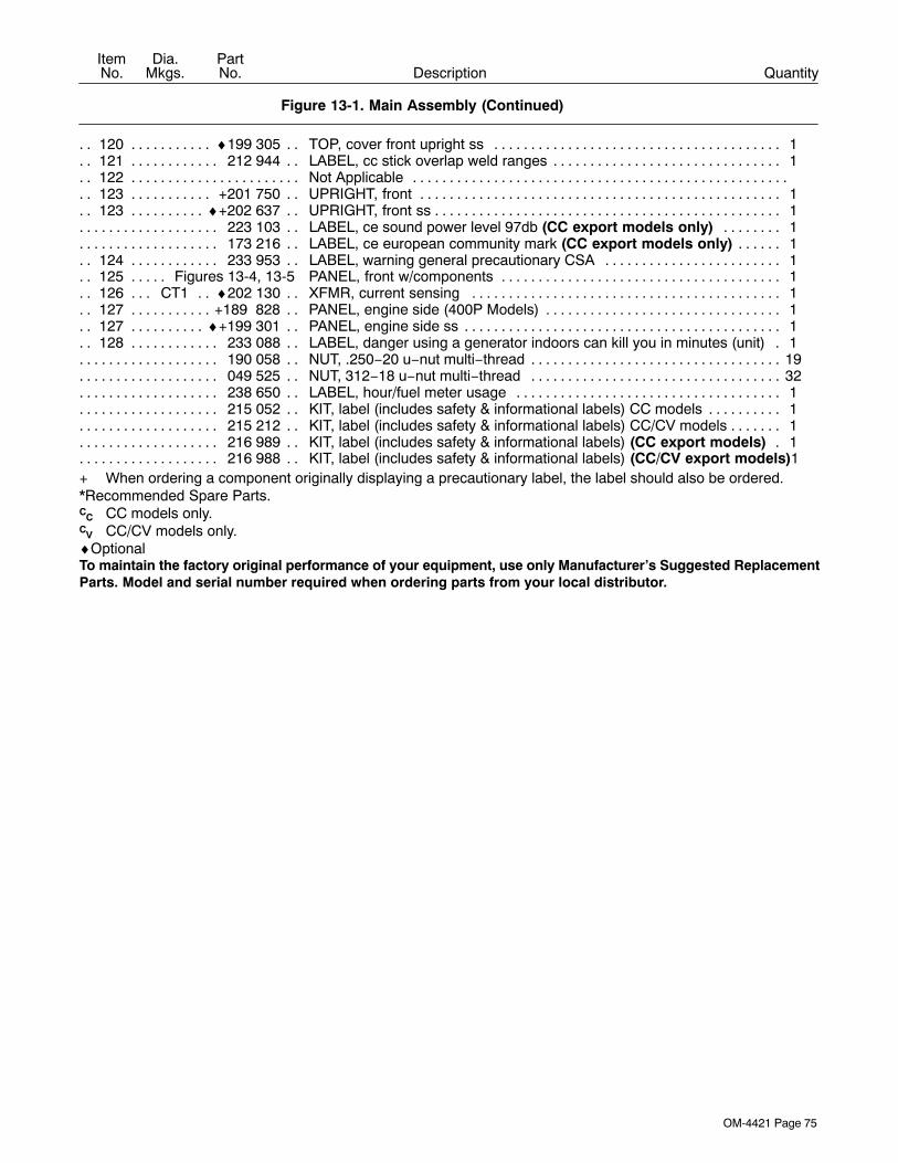
OM-4421 Page 75
DescriptionPartNo.
Dia.Mkgs.
ItemNo.
Figure 13-1. Main Assembly (Continued)
Quantity
120 ♦199 305 TOP, cover front upright ss 1. . . . . . . . . . . . . . . . . . . . . . . . . . . . . . . . . . . . . . . . . . . . . . . . . . . . . .121 212 944 LABEL, cc stick overlap weld ranges 1. . . . . . . . . . . . . . . . . . . . . . . . . . . . . . . . . . . . . . . . . . . . . . .122 Not Applicable. . . . . . . . . . . . . . . . . . . . . . . . . . . . . . . . . . . . . . . . . . . . . . . . . . . . . . . . . . . . . . . . . . . . . . . . . . . .123 +201 750 UPRIGHT, front 1. . . . . . . . . . . . . . . . . . . . . . . . . . . . . . . . . . . . . . . . . . . . . . . . . . . . . . . . . . . . . . . .123 ♦+202 637 UPRIGHT, front ss 1. . . . . . . . . . . . . . . . . . . . . . . . . . . . . . . . . . . . . . . . . . . . . . . . . . . . . . . . . . . . .
223 103 LABEL, ce sound power level 97db (CC export models only) 1. . . . . . . . . . . . . . . . . . . . . . . . . . . . .173 216 LABEL, ce european community mark (CC export models only) 1. . . . . . . . . . . . . . . . . . . . . . . . . . .
124 233 953 LABEL, warning general precautionary CSA 1. . . . . . . . . . . . . . . . . . . . . . . . . . . . . . . . . . . . . . . .125 Figures 13-4, 13-5 PANEL, front w/components 1. . . . . . . . . . . . . . . . . . . . . . . . . . . . . . . . . . . . . . . . . . . . .126 CT1 ♦202 130 XFMR, current sensing 1. . . . . . . . . . . . . . . . . . . . . . . . . . . . . . . . . . . . . . . . . . . . . . . . . . .127 +189 828 PANEL, engine side (400P Models) 1. . . . . . . . . . . . . . . . . . . . . . . . . . . . . . . . . . . . . . . . . . . . . . .127 ♦+199 301 PANEL, engine side ss 1. . . . . . . . . . . . . . . . . . . . . . . . . . . . . . . . . . . . . . . . . . . . . . . . . . . . . . . . .128 233 088 LABEL, danger using a generator indoors can kill you in minutes (unit) 1. . . . . . . . . . . . . . . . .
190 058 NUT, .250−20 u−nut multi−thread 19. . . . . . . . . . . . . . . . . . . . . . . . . . . . . . . . . . . . . . . . . . . . . . . . . . . . . . .049 525 NUT, 312−18 u−nut multi−thread 32. . . . . . . . . . . . . . . . . . . . . . . . . . . . . . . . . . . . . . . . . . . . . . . . . . . . . . .238 650 LABEL, hour/fuel meter usage 1. . . . . . . . . . . . . . . . . . . . . . . . . . . . . . . . . . . . . . . . . . . . . . . . . . . . . . . . .215 052 KIT, label (includes safety & informational labels) CC models 1. . . . . . . . . . . . . . . . . . . . . . . . . . . . . . .215 212 KIT, label (includes safety & informational labels) CC/CV models 1. . . . . . . . . . . . . . . . . . . . . . . . . . . .216 989 KIT, label (includes safety & informational labels) (CC export models) 1. . . . . . . . . . . . . . . . . . . . . .216 988 KIT, label (includes safety & informational labels) (CC/CV export models)1. . . . . . . . . . . . . . . . . . . . .
+ When ordering a component originally displaying a precautionary label, the label should also be ordered.*Recommended Spare Parts.CC CC models only.CV CC/CV models only.♦OptionalTo maintain the factory original performance of your equipment, use only Manufacturer’s Suggested ReplacementParts. Model and serial number required when ordering parts from your local distributor.
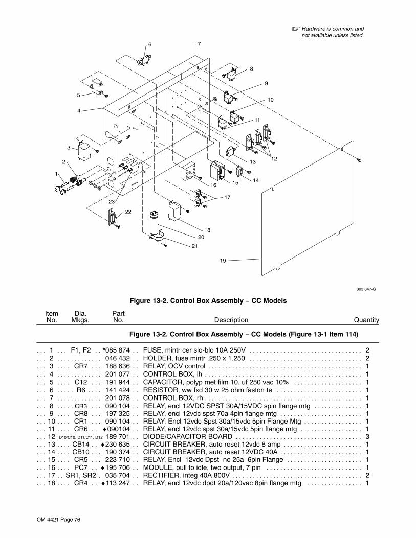
OM-4421 Page 76
� Hardware is common andnot available unless listed.
803 647-G
2
1
23
22
5
4
3
6
14
2018
21
19
16 15
17
8
11
7
10
12
9
13
Figure 13-2. Control Box Assembly − CC Models
DescriptionPartNo.
Dia.Mkgs.
ItemNo.
Figure 13-2. Control Box Assembly − CC Models (Figure 13-1 Item 114)
Quantity
1 F1, F2 *085 874 FUSE, mintr cer slo-blo 10A 250V 2. . . . . . . . . . . . . . . . . . . . . . . . . . . . . . . . . . . . . . . . . . .2 046 432 HOLDER, fuse mintr .250 x 1.250 2. . . . . . . . . . . . . . . . . . . . . . . . . . . . . . . . . . . . . . . . . . . . . . . . . . .3 CR7 188 636 RELAY, OCV control 1. . . . . . . . . . . . . . . . . . . . . . . . . . . . . . . . . . . . . . . . . . . . . . . . . . . . . . . . .4 201 077 CONTROL BOX, lh 1. . . . . . . . . . . . . . . . . . . . . . . . . . . . . . . . . . . . . . . . . . . . . . . . . . . . . . . . . . . . . . . .5 C12 191 944 CAPACITOR, polyp met film 10. uf 250 vac 10% 1. . . . . . . . . . . . . . . . . . . . . . . . . . . . . . . .6 R6 141 424 RESISTOR, ww fxd 30 w 25 ohm faston te 1. . . . . . . . . . . . . . . . . . . . . . . . . . . . . . . . . . . . . . .7 201 078 CONTROL BOX, rh 1. . . . . . . . . . . . . . . . . . . . . . . . . . . . . . . . . . . . . . . . . . . . . . . . . . . . . . . . . . . . . . . .8 CR3 090 104 RELAY, encl 12VDC SPST 30A/15VDC spin flange mtg 1. . . . . . . . . . . . . . . . . . . . . . . . . . .9 CR8 197 325 RELAY, encl 12vdc spst 70a 4pin flange mtg 1. . . . . . . . . . . . . . . . . . . . . . . . . . . . . . . . . . . .
10 CR1 090 104 RELAY, Encl 12vdc Spst 30a/15vdc 5pin Flange Mtg 1. . . . . . . . . . . . . . . . . . . . . . . . . . . . .11 CR6 ♦090104 RELAY, encl 12vdc spst 30a/15vdc 5pin flange mtg 1. . . . . . . . . . . . . . . . . . . . . . . . . . . . .12 D10/C10, D11/C11, D12 189 701 DIODE/CAPACITOR BOARD 3. . . . . . . . . . . . . . . . . . . . . . . . . . . . . . . . . . . . . . . . . .13 CB14 ♦230 635 CIRCUIT BREAKER, auto reset 12vdc 8 amp 1. . . . . . . . . . . . . . . . . . . . . . . . . . . . . . . . . .14 CB10 190 374 CIRCUIT BREAKER, auto reset 12VDC 40A 1. . . . . . . . . . . . . . . . . . . . . . . . . . . . . . . . . . . .15 CR5 223 710 RELAY, Encl 12vdc Dpst−no 25a 6pin Flange 1. . . . . . . . . . . . . . . . . . . . . . . . . . . . . . . . . .16 PC7 ♦195 706 MODULE, pull to idle, two output, 7 pin 1. . . . . . . . . . . . . . . . . . . . . . . . . . . . . . . . . . . . . . .17 SR1, SR2 035 704 RECTIFIER, integ 40A 800V 2. . . . . . . . . . . . . . . . . . . . . . . . . . . . . . . . . . . . . . . . . . . . . .18 CR4 ♦113 247 RELAY, encl 12vdc dpdt 20a/120vac 8pin flange mtg 1. . . . . . . . . . . . . . . . . . . . . . . . . . .

OM-4421 Page 77
DescriptionPartNo.
Dia.Mkgs.
ItemNo.
Figure 13-2. Control Box Assembly − CC Models Continued
Quantity
19 201 079 COVER, control box 1. . . . . . . . . . . . . . . . . . . . . . . . . . . . . . . . . . . . . . . . . . . . . . . . . . . . . . . . . . . . . . .20 C9 087 110 CAPACITOR, elctlt 240uf 200VDC 1. . . . . . . . . . . . . . . . . . . . . . . . . . . . . . . . . . . . . . . . . . . . . . . .21 177 136 CLAMP, capacitor 1.375dia 1. . . . . . . . . . . . . . . . . . . . . . . . . . . . . . . . . . . . . . . . . . . . . . . . . . . . . . . . .22 D1/C1 189 701 DIODE/CAPACITOR BOARD 1. . . . . . . . . . . . . . . . . . . . . . . . . . . . . . . . . . . . . . . . . . . . . . .23 CB11, 12, 13 139 266 SUPPLEMENTARY PROTECTOR, man reset 1p 15a 250vac 3. . . . . . . . . . . . .
♦Optional
*Recommended Spare Parts.To maintain the factory original performance of your equipment, use only Manufacturer’s SuggestedReplacement Parts. Model and serial number required when ordering parts from your local distributor.
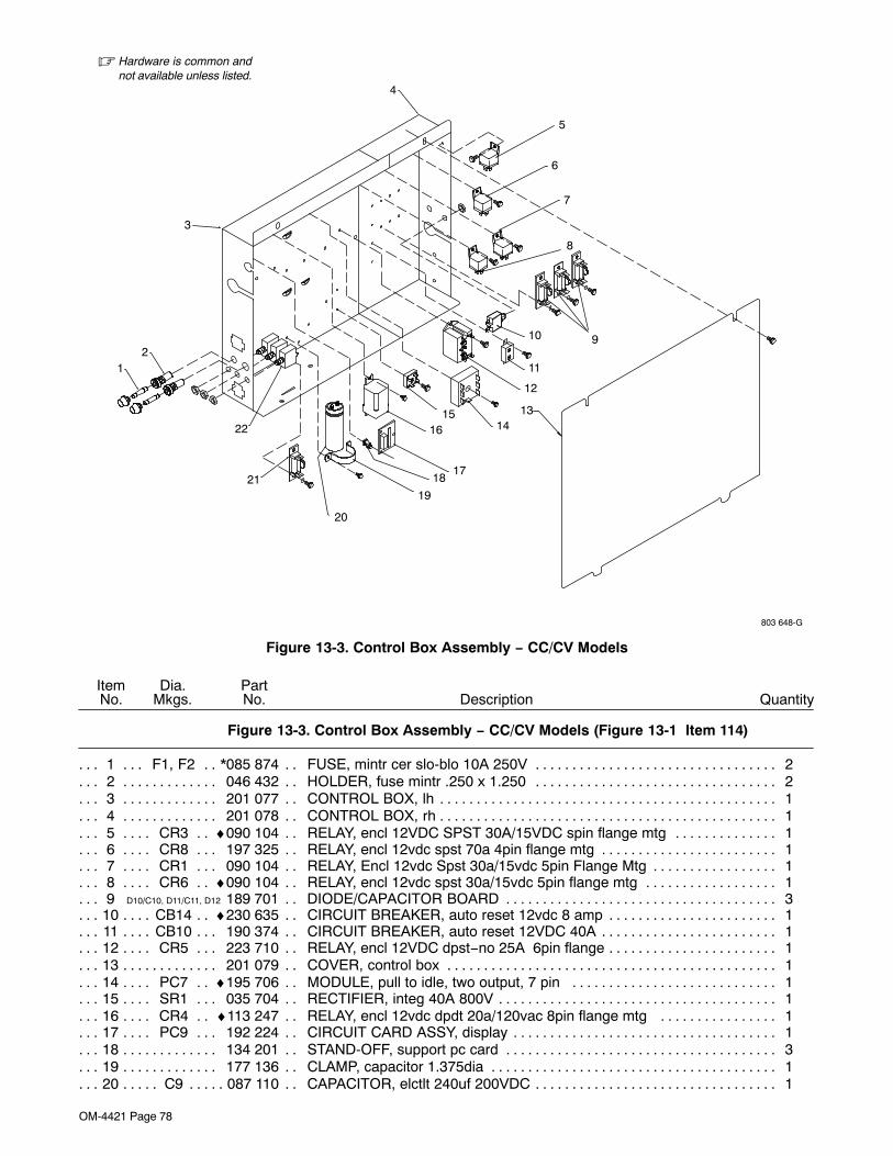
OM-4421 Page 78
� Hardware is common andnot available unless listed.
803 648-G
12
3
16
20
18
19
17
1514
5
11
8
4
7
9
6
12
22
21
10
13
Figure 13-3. Control Box Assembly − CC/CV Models
DescriptionPartNo.
Dia.Mkgs.
ItemNo.
Figure 13-3. Control Box Assembly − CC/CV Models (Figure 13-1 Item 114)
Quantity
1 F1, F2 *085 874 FUSE, mintr cer slo-blo 10A 250V 2. . . . . . . . . . . . . . . . . . . . . . . . . . . . . . . . . . . . . . . . . . .2 046 432 HOLDER, fuse mintr .250 x 1.250 2. . . . . . . . . . . . . . . . . . . . . . . . . . . . . . . . . . . . . . . . . . . . . . . . . . .3 201 077 CONTROL BOX, lh 1. . . . . . . . . . . . . . . . . . . . . . . . . . . . . . . . . . . . . . . . . . . . . . . . . . . . . . . . . . . . . . . .4 201 078 CONTROL BOX, rh 1. . . . . . . . . . . . . . . . . . . . . . . . . . . . . . . . . . . . . . . . . . . . . . . . . . . . . . . . . . . . . . . .5 CR3 ♦090 104 RELAY, encl 12VDC SPST 30A/15VDC spin flange mtg 1. . . . . . . . . . . . . . . . . . . . . . . . .6 CR8 197 325 RELAY, encl 12vdc spst 70a 4pin flange mtg 1. . . . . . . . . . . . . . . . . . . . . . . . . . . . . . . . . . . .7 CR1 090 104 RELAY, Encl 12vdc Spst 30a/15vdc 5pin Flange Mtg 1. . . . . . . . . . . . . . . . . . . . . . . . . . . . .8 CR6 ♦090 104 RELAY, encl 12vdc spst 30a/15vdc 5pin flange mtg 1. . . . . . . . . . . . . . . . . . . . . . . . . . . . .9 D10/C10, D11/C11, D12 189 701 DIODE/CAPACITOR BOARD 3. . . . . . . . . . . . . . . . . . . . . . . . . . . . . . . . . . . . . . . . . .
10 CB14 ♦230 635 CIRCUIT BREAKER, auto reset 12vdc 8 amp 1. . . . . . . . . . . . . . . . . . . . . . . . . . . . . . . . . .11 CB10 190 374 CIRCUIT BREAKER, auto reset 12VDC 40A 1. . . . . . . . . . . . . . . . . . . . . . . . . . . . . . . . . . . .12 CR5 223 710 RELAY, encl 12VDC dpst−no 25A 6pin flange 1. . . . . . . . . . . . . . . . . . . . . . . . . . . . . . . . . . .13 201 079 COVER, control box 1. . . . . . . . . . . . . . . . . . . . . . . . . . . . . . . . . . . . . . . . . . . . . . . . . . . . . . . . . . . . . . .14 PC7 ♦195 706 MODULE, pull to idle, two output, 7 pin 1. . . . . . . . . . . . . . . . . . . . . . . . . . . . . . . . . . . . . . .15 SR1 035 704 RECTIFIER, integ 40A 800V 1. . . . . . . . . . . . . . . . . . . . . . . . . . . . . . . . . . . . . . . . . . . . . . . . . .16 CR4 ♦113 247 RELAY, encl 12vdc dpdt 20a/120vac 8pin flange mtg 1. . . . . . . . . . . . . . . . . . . . . . . . . . .17 PC9 192 224 CIRCUIT CARD ASSY, display 1. . . . . . . . . . . . . . . . . . . . . . . . . . . . . . . . . . . . . . . . . . . . . . . .18 134 201 STAND-OFF, support pc card 3. . . . . . . . . . . . . . . . . . . . . . . . . . . . . . . . . . . . . . . . . . . . . . . . . . . . . . .19 177 136 CLAMP, capacitor 1.375dia 1. . . . . . . . . . . . . . . . . . . . . . . . . . . . . . . . . . . . . . . . . . . . . . . . . . . . . . . . .20 C9 087 110 CAPACITOR, elctlt 240uf 200VDC 1. . . . . . . . . . . . . . . . . . . . . . . . . . . . . . . . . . . . . . . . . . . . . . . .

OM-4421 Page 79
DescriptionPartNo.
Dia.Mkgs.
ItemNo.
Figure 13-3. Control Box Assembly − CC/CV Models (Continued)
Quantity
21 D1/C1 189 701 DIODE/CAPACITOR BOARD 1. . . . . . . . . . . . . . . . . . . . . . . . . . . . . . . . . . . . . . . . . . . . . . .22 CB11, 12, 13 139 266 SUPPLEMENTARY PROTECTOR, man reset 1p 15a 250vac 3. . . . . . . . . . . . .
♦Optional
*Recommended Spare Parts.To maintain the factory original performance of your equipment, use only Manufacturer’s SuggestedReplacement Parts. Model and serial number required when ordering parts from your local distributor.
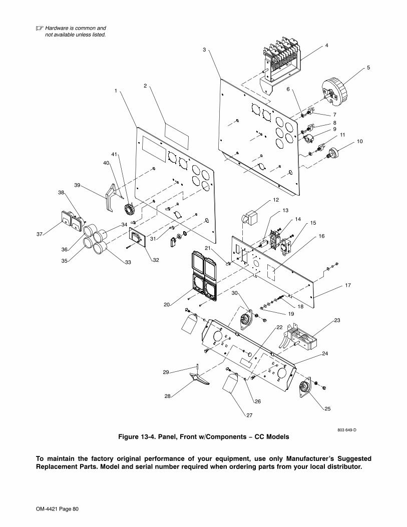
OM-4421 Page 80
� Hardware is common andnot available unless listed.
803 649-D
12
34
5
6
7
89
1110
12
13
1415
16
1819
2223
24
2526
27
29
30
20
21
31
3233
34
35
36
37
3839
40
41
17
28
Figure 13-4. Panel, Front w/Components − CC Models
To maintain the factory original performance of your equipment, use only Manufacturer’s SuggestedReplacement Parts. Model and serial number required when ordering parts from your local distributor.
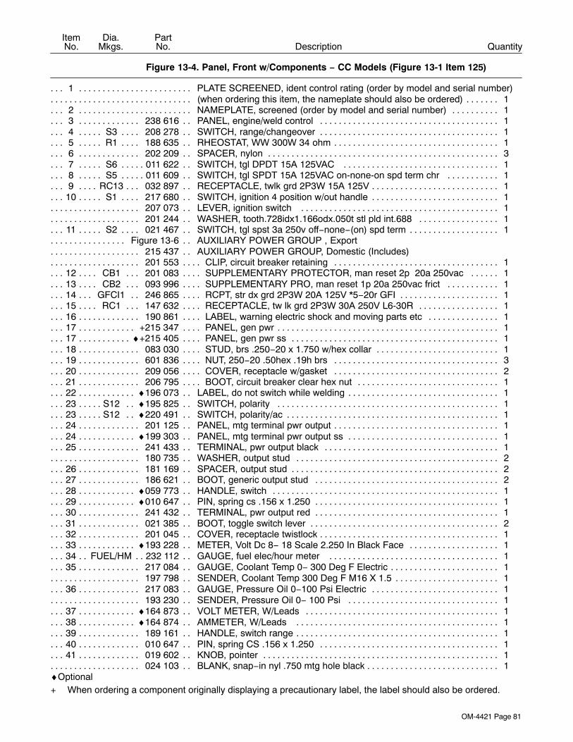
OM-4421 Page 81
DescriptionPartNo.
Dia.Mkgs.
ItemNo.
Figure 13-4. Panel, Front w/Components − CC Models (Figure 13-1 Item 125)
Quantity
1 PLATE SCREENED, ident control rating (order by model and serial number). . . . . . . . . . . . . . . . . . . . . . . . . . .(when ordering this item, the nameplate should also be ordered) 1. . . . . . . . . . . . . . . . . . . . . . . . . . . . . . . . . . . . .
2 NAMEPLATE, screened (order by model and serial number) 1. . . . . . . . . . . . . . . . . . . . . . . . . . . . . . . . . . . . .3 238 616 PANEL, engine/weld control 1. . . . . . . . . . . . . . . . . . . . . . . . . . . . . . . . . . . . . . . . . . . . . . . . . . . . . . . .4 S3 208 278 SWITCH, range/changeover 1. . . . . . . . . . . . . . . . . . . . . . . . . . . . . . . . . . . . . . . . . . . . . . . . . . . .5 R1 188 635 RHEOSTAT, WW 300W 34 ohm 1. . . . . . . . . . . . . . . . . . . . . . . . . . . . . . . . . . . . . . . . . . . . . . . . .6 202 209 SPACER, nylon 3. . . . . . . . . . . . . . . . . . . . . . . . . . . . . . . . . . . . . . . . . . . . . . . . . . . . . . . . . . . . . . . . . . .7 S6 011 622 SWITCH, tgl DPDT 15A 125VAC 1. . . . . . . . . . . . . . . . . . . . . . . . . . . . . . . . . . . . . . . . . . . . . . . .8 S5 011 609 SWITCH, tgl SPDT 15A 125VAC on-none-on spd term chr 1. . . . . . . . . . . . . . . . . . . . . . . . . .9 RC13 032 897 RECEPTACLE, twlk grd 2P3W 15A 125V 1. . . . . . . . . . . . . . . . . . . . . . . . . . . . . . . . . . . . . . .
10 S1 217 680 SWITCH, ignition 4 position w/out handle 1. . . . . . . . . . . . . . . . . . . . . . . . . . . . . . . . . . . . . . . . .207 073 LEVER, ignition switch 1. . . . . . . . . . . . . . . . . . . . . . . . . . . . . . . . . . . . . . . . . . . . . . . . . . . . . . . . . . . . . . .201 244 WASHER, tooth.728idx1.166odx.050t stl pld int.688 1. . . . . . . . . . . . . . . . . . . . . . . . . . . . . . . . . . . . . .
11 S2 021 467 SWITCH, tgl spst 3a 250v off−none−(on) spd term 1. . . . . . . . . . . . . . . . . . . . . . . . . . . . . . . . .Figure 13-6 AUXILIARY POWER GROUP , Export. . . . . . . . . . . . . . . . . .
215 437 AUXILIARY POWER GROUP, Domestic (Includes). . . . . . . . . . . . . . . . . . . . .201 553 CLIP, circuit breaker retaining 1. . . . . . . . . . . . . . . . . . . . . . . . . . . . . . . . . . . . . . . . . . . . . . . . . . . . . . . . . .
12 CB1 201 083 SUPPLEMENTARY PROTECTOR, man reset 2p 20a 250vac 1. . . . . . . . . . . . . . . . . . . .13 CB2 093 996 SUPPLEMENTARY PRO, man reset 1p 20a 250vac frict 1. . . . . . . . . . . . . . . . . . . . . . . . .14 GFCI1 246 865 RCPT, str dx grd 2P3W 20A 125V *5−20r GFI 1. . . . . . . . . . . . . . . . . . . . . . . . . . . . . . . . .15 RC1 147 632 RECEPTACLE, tw lk grd 2P3W 30A 250V L6-30R 1. . . . . . . . . . . . . . . . . . . . . . . . . . . . . . .16 190 861 LABEL, warning electric shock and moving parts etc 1. . . . . . . . . . . . . . . . . . . . . . . . . . . . . . . . . . .17 +215 347 PANEL, gen pwr 1. . . . . . . . . . . . . . . . . . . . . . . . . . . . . . . . . . . . . . . . . . . . . . . . . . . . . . . . . . . . . . . . . .17 ♦+215 405 PANEL, gen pwr ss 1. . . . . . . . . . . . . . . . . . . . . . . . . . . . . . . . . . . . . . . . . . . . . . . . . . . . . . . . . . . . . .18 083 030 STUD, brs .250−20 x 1.750 w/hex collar 1. . . . . . . . . . . . . . . . . . . . . . . . . . . . . . . . . . . . . . . . . . . . . .19 601 836 NUT, 250−20 .50hex .19h brs 3. . . . . . . . . . . . . . . . . . . . . . . . . . . . . . . . . . . . . . . . . . . . . . . . . . . . . . .20 209 056 COVER, receptacle w/gasket 2. . . . . . . . . . . . . . . . . . . . . . . . . . . . . . . . . . . . . . . . . . . . . . . . . . . . . . .21 206 795 BOOT, circuit breaker clear hex nut 1. . . . . . . . . . . . . . . . . . . . . . . . . . . . . . . . . . . . . . . . . . . . . . . . . .22 ♦196 073 LABEL, do not switch while welding 1. . . . . . . . . . . . . . . . . . . . . . . . . . . . . . . . . . . . . . . . . . . . . . . . .23 S12 ♦195 825 SWITCH, polarity 1. . . . . . . . . . . . . . . . . . . . . . . . . . . . . . . . . . . . . . . . . . . . . . . . . . . . . . . . . . .23 S12 ♦220 491 SWITCH, polarity/ac 1. . . . . . . . . . . . . . . . . . . . . . . . . . . . . . . . . . . . . . . . . . . . . . . . . . . . . . . . .24 201 125 PANEL, mtg terminal pwr output 1. . . . . . . . . . . . . . . . . . . . . . . . . . . . . . . . . . . . . . . . . . . . . . . . . . . . .24 ♦199 303 PANEL, mtg terminal pwr output ss 1. . . . . . . . . . . . . . . . . . . . . . . . . . . . . . . . . . . . . . . . . . . . . . . . .25 241 433 TERMINAL, pwr output black 1. . . . . . . . . . . . . . . . . . . . . . . . . . . . . . . . . . . . . . . . . . . . . . . . . . . . . . .
180 735 WASHER, output stud 2. . . . . . . . . . . . . . . . . . . . . . . . . . . . . . . . . . . . . . . . . . . . . . . . . . . . . . . . . . . . . . . .26 181 169 SPACER, output stud 2. . . . . . . . . . . . . . . . . . . . . . . . . . . . . . . . . . . . . . . . . . . . . . . . . . . . . . . . . . . . . .27 186 621 BOOT, generic output stud 2. . . . . . . . . . . . . . . . . . . . . . . . . . . . . . . . . . . . . . . . . . . . . . . . . . . . . . . . .28 ♦059 773 HANDLE, switch 1. . . . . . . . . . . . . . . . . . . . . . . . . . . . . . . . . . . . . . . . . . . . . . . . . . . . . . . . . . . . . . . . .29 ♦010 647 PIN, spring cs .156 x 1.250 1. . . . . . . . . . . . . . . . . . . . . . . . . . . . . . . . . . . . . . . . . . . . . . . . . . . . . . . .30 241 432 TERMINAL, pwr output red 1. . . . . . . . . . . . . . . . . . . . . . . . . . . . . . . . . . . . . . . . . . . . . . . . . . . . . . . . .31 021 385 BOOT, toggle switch lever 2. . . . . . . . . . . . . . . . . . . . . . . . . . . . . . . . . . . . . . . . . . . . . . . . . . . . . . . . . .32 201 045 COVER, receptacle twistlock 1. . . . . . . . . . . . . . . . . . . . . . . . . . . . . . . . . . . . . . . . . . . . . . . . . . . . . . . .33 ♦193 228 METER, Volt Dc 8− 18 Scale 2.250 In Black Face 1. . . . . . . . . . . . . . . . . . . . . . . . . . . . . . . . . . . .34 FUEL/HM 232 112 GAUGE, fuel elec/hour meter 1. . . . . . . . . . . . . . . . . . . . . . . . . . . . . . . . . . . . . . . . . . . . .35 217 084 GAUGE, Coolant Temp 0− 300 Deg F Electric 1. . . . . . . . . . . . . . . . . . . . . . . . . . . . . . . . . . . . . . . . .
197 798 SENDER, Coolant Temp 300 Deg F M16 X 1.5 1. . . . . . . . . . . . . . . . . . . . . . . . . . . . . . . . . . . . . . . . . . .36 217 083 GAUGE, Pressure Oil 0−100 Psi Electric 1. . . . . . . . . . . . . . . . . . . . . . . . . . . . . . . . . . . . . . . . . . . . .
193 230 SENDER, Pressure Oil 0− 100 Psi 1. . . . . . . . . . . . . . . . . . . . . . . . . . . . . . . . . . . . . . . . . . . . . . . . . . . . .37 ♦164 873 VOLT METER, W/Leads 1. . . . . . . . . . . . . . . . . . . . . . . . . . . . . . . . . . . . . . . . . . . . . . . . . . . . . . . . . .38 ♦164 874 AMMETER, W/Leads 1. . . . . . . . . . . . . . . . . . . . . . . . . . . . . . . . . . . . . . . . . . . . . . . . . . . . . . . . . . . .39 189 161 HANDLE, switch range 1. . . . . . . . . . . . . . . . . . . . . . . . . . . . . . . . . . . . . . . . . . . . . . . . . . . . . . . . . . . . .40 010 647 PIN, spring CS .156 x 1.250 1. . . . . . . . . . . . . . . . . . . . . . . . . . . . . . . . . . . . . . . . . . . . . . . . . . . . . . . .41 019 602 KNOB, pointer 1. . . . . . . . . . . . . . . . . . . . . . . . . . . . . . . . . . . . . . . . . . . . . . . . . . . . . . . . . . . . . . . . . . . .
024 103 BLANK, snap−in nyl .750 mtg hole black 1. . . . . . . . . . . . . . . . . . . . . . . . . . . . . . . . . . . . . . . . . . . . . . . . .♦Optional+ When ordering a component originally displaying a precautionary label, the label should also be ordered.
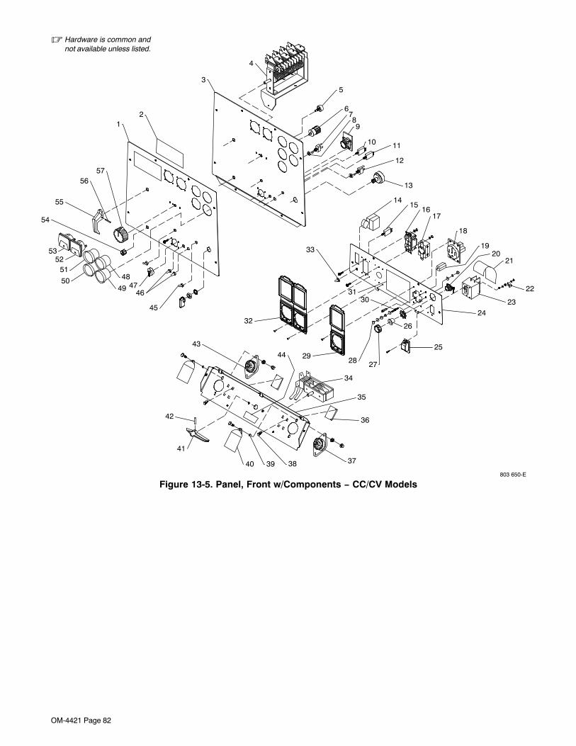
OM-4421 Page 82
� Hardware is common andnot available unless listed.
803 650-E
11
31
14
30
27
53
42
5251
50
464749
48
44
3940
41
38 37
36
35
43
34
2928
33
2
55
54
5657
17
6
8
10
9
35
4
19
24
20
25
26
22
23
21
1716
15
18
13
12
32
45
Figure 13-5. Panel, Front w/Components − CC/CV Models
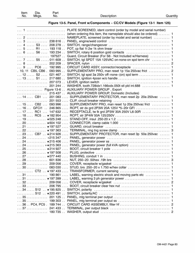
OM-4421 Page 83
DescriptionPartNo.
Dia.Mkgs.
ItemNo.
Figure 13-5. Panel, Front w/Components − CC/CV Models (Figure 13-1 Item 125)
Quantity
1 PLATE SCREENED, ident control (order by model and serial number). . . . . . . . . . . . . . . . . . . . . . . . . . .(when ordering this item, the nameplate should also be ordered) 1. . . . . . . . . . . . . . . . . . . . . . . . . . . . . . . . . . . . .
2 NAMEPLATE, screened (order by model and serial number) 1. . . . . . . . . . . . . . . . . . . . . . . . . . . . . . . . . . . . .3 238 616 PANEL, engine/weld control 1. . . . . . . . . . . . . . . . . . . . . . . . . . . . . . . . . . . . . . . . . . . . . . . . . . . . . . . .4 S3 208 278 SWITCH, range/changeover 1. . . . . . . . . . . . . . . . . . . . . . . . . . . . . . . . . . . . . . . . . . . . . . . . . . . .5 R1 193 118 POT, cp flat 1t 2w 1k ohm linear 1. . . . . . . . . . . . . . . . . . . . . . . . . . . . . . . . . . . . . . . . . . . . . . . . . .6 S6 193 234 SWITCH, rotary 6 position gold contacts 1. . . . . . . . . . . . . . . . . . . . . . . . . . . . . . . . . . . . . . . . .
197527 Guard, Circuit Breaker (For S6 - Not Included w/Harness) 1. . . . . . . . . . . . . . . . . . . . . . . . . . . . . . . . . .7 S5 011 609 SWITCH, tgl SPDT 15A 125VAC on-none-on spd term chr 1. . . . . . . . . . . . . . . . . . . . . . . . . .8 202 209 SPACER, nylon 2. . . . . . . . . . . . . . . . . . . . . . . . . . . . . . . . . . . . . . . . . . . . . . . . . . . . . . . . . . . . . . . . . . .9 PC6 192 995 CIRCUIT CARD ASSY, connector/receptacle 1. . . . . . . . . . . . . . . . . . . . . . . . . . . . . . . . . . .
10, 11 CB5, CB6 093 995 SUPPLEMENTARY PRO, man reset 1p 15a 250vac frict 2. . . . . . . . . . . . . . . . .12 S2 021 467 SWITCH, tgl spst 3a 250v off−none−(on) spd term 1. . . . . . . . . . . . . . . . . . . . . . . . . . . . . . . . .13 S1 217 680 SWITCH, ignition 4posn w/o handle 1. . . . . . . . . . . . . . . . . . . . . . . . . . . . . . . . . . . . . . . . . . . . . .
207 073 LEVER, ignition switch 1. . . . . . . . . . . . . . . . . . . . . . . . . . . . . . . . . . . . . . . . . . . . . . . . . . . . . . . . . . . . . . .201 244 WASHER, tooth.728idx1.166odx.050t stl pld int.688 1. . . . . . . . . . . . . . . . . . . . . . . . . . . . . . . . . . . . . .
Figure 13-6 AUXILIARY POWER GROUP , Export. . . . . . . . . . . . . . . . . .215 437 AUXILIARY POWER GROUP, Domestic (Includes). . . . . . . . . . . . . . . . . . . . .
14 CB1 201 083 SUPPLEMENTARY PROTECTOR, man reset 2p 20a 250vac 1. . . . . . . . . . . . . . . . . . . .201 553 CLIP, circuit breaker retaining 1. . . . . . . . . . . . . . . . . . . . . . . . . . . . . . . . . . . . . . . . . . . . . . . . . . . . . . . . . .
15 CB2 093 996 SUPPLEMENTARY PRO, man reset 1p 20a 250vac frict 1. . . . . . . . . . . . . . . . . . . . . . . . .16 GFCI1 246 865 RCPT, str dx grd 2P3W 20A 125V *5−20r GFI 1. . . . . . . . . . . . . . . . . . . . . . . . . . . . . . . . .17 RC1 147 632 RECEPTACLE, tw lk grd 2P3W 30A 250V L6-30R 1. . . . . . . . . . . . . . . . . . . . . . . . . . . . . . .18 RC5 ♦182 954 RCPT, str 3P4W 50A 125/250V 1. . . . . . . . . . . . . . . . . . . . . . . . . . . . . . . . . . . . . . . . . . . . . . .19 ♦025 248 STAND-OFF, insul .250-20 x 1.2 1. . . . . . . . . . . . . . . . . . . . . . . . . . . . . . . . . . . . . . . . . . . . . . . . . . . .20 ♦604 102 CONNECTOR, clamp cable 1.000 1. . . . . . . . . . . . . . . . . . . . . . . . . . . . . . . . . . . . . . . . . . . . . . . . . .21 ♦197 527 GUARD, circuit breaker 1. . . . . . . . . . . . . . . . . . . . . . . . . . . . . . . . . . . . . . . . . . . . . . . . . . . . . . . . . . .22 ♦197 363 TERMINAL, ring tng screw clamp 3. . . . . . . . . . . . . . . . . . . . . . . . . . . . . . . . . . . . . . . . . . . . . . . . . . .23 CB7 ♦214 926 SUPPLEMENTARY PROTECTOR, man reset 3p 50a 250vac 1. . . . . . . . . . . . . . . . . . .24 +215 347 PANEL, generator power 1. . . . . . . . . . . . . . . . . . . . . . . . . . . . . . . . . . . . . . . . . . . . . . . . . . . . . . . . . .24 ♦215 406 PANEL, generator power ss 1. . . . . . . . . . . . . . . . . . . . . . . . . . . . . . . . . . . . . . . . . . . . . . . . . . . . . . . .24 +♦215 363 PANEL, generator power (full kVA option) 1. . . . . . . . . . . . . . . . . . . . . . . . . . . . . . . . . . . . . . . . . . .25 ♦214 927 BOOT, circuit breaker 1 pole 1. . . . . . . . . . . . . . . . . . . . . . . . . . . . . . . . . . . . . . . . . . . . . . . . . . . . . . .26 ♦197 508 PLUG, protective 1. . . . . . . . . . . . . . . . . . . . . . . . . . . . . . . . . . . . . . . . . . . . . . . . . . . . . . . . . . . . . . . . .27 ♦077 440 BUSHING, conduit 1 in 1. . . . . . . . . . . . . . . . . . . . . . . . . . . . . . . . . . . . . . . . . . . . . . . . . . . . . . . . . . . .28 601 836 NUT, 250−20 .50hex .19h brs 3. . . . . . . . . . . . . . . . . . . . . . . . . . . . . . . . . . . . . . . . . . . . . . . . . . . . . . .29 209 056 COVER, receptacle w/gasket 1. . . . . . . . . . . . . . . . . . . . . . . . . . . . . . . . . . . . . . . . . . . . . . . . . . . . . . .30 083 030 STUD, brs .250−20 x 1.750 w/hex collar 1. . . . . . . . . . . . . . . . . . . . . . . . . . . . . . . . . . . . . . . . . . . . . .
CT2 ♦197 433 TRANSFORMER, current sensing 1. . . . . . . . . . . . . . . . . . . . . . . . . . . . . . . . . . . . . . . . . . . . . . .31 190 861 LABEL, warning electric shock and moving parts etc 1. . . . . . . . . . . . . . . . . . . . . . . . . . . . . . . . . . .31 ♦197 399 LABEL, warning 3 ph generator power 1. . . . . . . . . . . . . . . . . . . . . . . . . . . . . . . . . . . . . . . . . . . . . . .32 209 056 COVER, receptacle w/gasket 2. . . . . . . . . . . . . . . . . . . . . . . . . . . . . . . . . . . . . . . . . . . . . . . . . . . . . . .33 206 795 BOOT, circuit breaker clear hex nut 1. . . . . . . . . . . . . . . . . . . . . . . . . . . . . . . . . . . . . . . . . . . . . . . . . .34 S12 ♦195 825 SWITCH, polarity 1. . . . . . . . . . . . . . . . . . . . . . . . . . . . . . . . . . . . . . . . . . . . . . . . . . . . . . . . . . .
S12 ♦220 491 SWITCH, polarity/AC 1. . . . . . . . . . . . . . . . . . . . . . . . . . . . . . . . . . . . . . . . . . . . . . . . . . . . . . . . . . .35 201 125 PANEL, mtg terminal pwr output 1. . . . . . . . . . . . . . . . . . . . . . . . . . . . . . . . . . . . . . . . . . . . . . . . . . . . .35 199 303 PANEL, mtg terminal pwr output ss 1. . . . . . . . . . . . . . . . . . . . . . . . . . . . . . . . . . . . . . . . . . . . . . . . . .36 PC4, PC5 189 744 CIRCUIT CARD ASSEMBLY, filter hf 2. . . . . . . . . . . . . . . . . . . . . . . . . . . . . . . . . . . . . . .37 241 433 TERMINAL, pwr output black 1. . . . . . . . . . . . . . . . . . . . . . . . . . . . . . . . . . . . . . . . . . . . . . . . . . . . . . .
180 735 WASHER, output stud 2. . . . . . . . . . . . . . . . . . . . . . . . . . . . . . . . . . . . . . . . . . . . . . . . . . . . . . . . . . . . . . . .
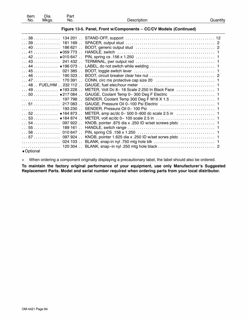
OM-4421 Page 84
DescriptionPartNo.
Dia.Mkgs.
ItemNo.
Figure 13-5. Panel, Front w/Components − CC/CV Models (Continued)
Quantity
38 134 201 STAND-OFF, support 12. . . . . . . . . . . . . . . . . . . . . . . . . . . . . . . . . . . . . . . . . . . . . . . . . . . . . . . . . . . . . .39 181 169 SPACER, output stud 2. . . . . . . . . . . . . . . . . . . . . . . . . . . . . . . . . . . . . . . . . . . . . . . . . . . . . . . . . . . . . .40 186 621 BOOT, generic output stud 2. . . . . . . . . . . . . . . . . . . . . . . . . . . . . . . . . . . . . . . . . . . . . . . . . . . . . . . . .41 ♦059 773 HANDLE, switch 1. . . . . . . . . . . . . . . . . . . . . . . . . . . . . . . . . . . . . . . . . . . . . . . . . . . . . . . . . . . . . . . . .42 ♦010 647 PIN, spring cs .156 x 1.250 1. . . . . . . . . . . . . . . . . . . . . . . . . . . . . . . . . . . . . . . . . . . . . . . . . . . . . . . .43 241 432 TERMINAL, pwr output red 1. . . . . . . . . . . . . . . . . . . . . . . . . . . . . . . . . . . . . . . . . . . . . . . . . . . . . . . . .44 ♦196 073 LABEL, do not switch while welding 1. . . . . . . . . . . . . . . . . . . . . . . . . . . . . . . . . . . . . . . . . . . . . . . . .45 021 385 BOOT, toggle switch lever 1. . . . . . . . . . . . . . . . . . . . . . . . . . . . . . . . . . . . . . . . . . . . . . . . . . . . . . . . . .46 190 323 BOOT, circuit breaker clear hex nut 2. . . . . . . . . . . . . . . . . . . . . . . . . . . . . . . . . . . . . . . . . . . . . . . . . .47 170 391 CONN, circ ms protective cap size 20 1. . . . . . . . . . . . . . . . . . . . . . . . . . . . . . . . . . . . . . . . . . . . . . .48 FUEL/HM 232 112 GAUGE, fuel elec/hour meter 1. . . . . . . . . . . . . . . . . . . . . . . . . . . . . . . . . . . . . . . . . . . . .49 ♦193 228 METER, Volt Dc 8− 18 Scale 2.250 In Black Face 1. . . . . . . . . . . . . . . . . . . . . . . . . . . . . . . . . . . .50 ♦217 084 GAUGE, Coolant Temp 0− 300 Deg F Electric 1. . . . . . . . . . . . . . . . . . . . . . . . . . . . . . . . . . . . . . .
197 798 SENDER, Coolant Temp 300 Deg F M16 X 1.5 1. . . . . . . . . . . . . . . . . . . . . . . . . . . . . . . . . . . . . . . . . . .51 217 083 GAUGE, Pressure Oil 0−100 Psi Electric 1. . . . . . . . . . . . . . . . . . . . . . . . . . . . . . . . . . . . . . . . . . . . .
193 230 SENDER, Pressure Oil 0− 100 Psi 1. . . . . . . . . . . . . . . . . . . . . . . . . . . . . . . . . . . . . . . . . . . . . . . . . . . . .52 ♦164 873 METER, amp ac/dc 0− 500 0−600 dc scale 2.5 in 1. . . . . . . . . . . . . . . . . . . . . . . . . . . . . . . . . . . .53 ♦164 874 METER, volt ac/dc 0− 100 scale 2.5 in 1. . . . . . . . . . . . . . . . . . . . . . . . . . . . . . . . . . . . . . . . . . . . . .54 097 922 KNOB, pointer .875 dia x .250 ID w/set screws plstc 1. . . . . . . . . . . . . . . . . . . . . . . . . . . . . . . . . . .55 189 161 HANDLE, switch range 1. . . . . . . . . . . . . . . . . . . . . . . . . . . . . . . . . . . . . . . . . . . . . . . . . . . . . . . . . . . . .56 010 647 PIN, spring CS .156 x 1.250 1. . . . . . . . . . . . . . . . . . . . . . . . . . . . . . . . . . . . . . . . . . . . . . . . . . . . . . . .57 097 924 KNOB, pointer 1.625 dia x .250 ID w/set scrws plstc 1. . . . . . . . . . . . . . . . . . . . . . . . . . . . . . . . . . .
024 103 BLANK, snap-in nyl .750 mtg hole blk 1. . . . . . . . . . . . . . . . . . . . . . . . . . . . . . . . . . . . . . . . . . . . . . . . . . .120 304 BLANK, snap−in nyl .250 mtg hole black 2. . . . . . . . . . . . . . . . . . . . . . . . . . . . . . . . . . . . . . . . . . . . . . . . .
♦Optional
+ When ordering a component originally displaying a precautionary label, the label should also be ordered.
To maintain the factory original performance of your equipment, use only Manufacturer’s SuggestedReplacement Parts. Model and serial number required when ordering parts from your local distributor.
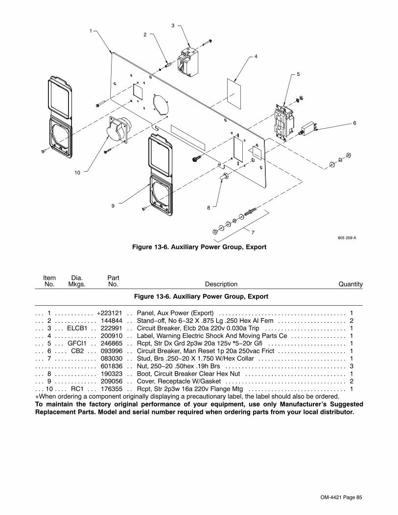
OM-4421 Page 85
805 259-A
12
3
4
5
89
10
7
6
Figure 13-6. Auxiliary Power Group, Export
DescriptionPartNo.
Dia.Mkgs.
ItemNo. Quantity
Figure 13-6. Auxiliary Power Group, Export
1 +223121 Panel, Aux Power (Export) 1. . . . . . . . . . . . . . . . . . . . . . . . . . . . . . . . . . . . . . . . . . . . . . . . . . . . . . . .2 144844 Stand−off, No 6−32 X .875 Lg .250 Hex Al Fem 2. . . . . . . . . . . . . . . . . . . . . . . . . . . . . . . . . . . . . . .3 ELCB1 222991 Circuit Breaker, Elcb 20a 220v 0.030a Trip 1. . . . . . . . . . . . . . . . . . . . . . . . . . . . . . . . . . .4 200910 Label, Warning Electric Shock And Moving Parts Ce 1. . . . . . . . . . . . . . . . . . . . . . . . . . . . . . . . . . .5 GFCI1 246865 Rcpt, Str Dx Grd 2p3w 20a 125v *5−20r Gfi 1. . . . . . . . . . . . . . . . . . . . . . . . . . . . . . . . . .6 CB2 093996 Circuit Breaker, Man Reset 1p 20a 250vac Frict 1. . . . . . . . . . . . . . . . . . . . . . . . . . . . . . . . .7 083030 Stud, Brs .250−20 X 1.750 W/Hex Collar 1. . . . . . . . . . . . . . . . . . . . . . . . . . . . . . . . . . . . . . . . . . . . .
601836 Nut, 250−20 .50hex .19h Brs 3. . . . . . . . . . . . . . . . . . . . . . . . . . . . . . . . . . . . . . . . . . . . . . . . . . . . . . . . . .8 190323 Boot, Circuit Breaker Clear Hex Nut 1. . . . . . . . . . . . . . . . . . . . . . . . . . . . . . . . . . . . . . . . . . . . . . . . .9 209056 Cover, Receptacle W/Gasket 2. . . . . . . . . . . . . . . . . . . . . . . . . . . . . . . . . . . . . . . . . . . . . . . . . . . . . . .
10 RC1 176355 Rcpt, Str 2p3w 16a 220v Flange Mtg 1. . . . . . . . . . . . . . . . . . . . . . . . . . . . . . . . . . . . . . . . . .+When ordering a component originally displaying a precautionary label, the label should also be ordered.To maintain the factory original performance of your equipment, use only Manufacturer’s SuggestedReplacement Parts. Model and serial number required when ordering parts from your local distributor.
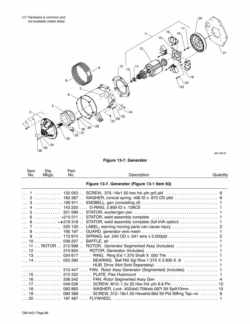
OM-4421 Page 86
802 552-B
� Hardware is common andnot available unless listed.
5
6
8
9
24
283031
3233
12
7
2526
3536
4
3
10
27
21
29
34
20
17
181115
16
12
1314
19
2223
Figure 13-7. Generator
DescriptionPartNo.
Dia.Mkgs.
ItemNo.
Figure 13-7. Generator (Figure 13-1 Item 93)
Quantity
1 132 053 SCREW, .375−16x1.50 hex hd−pln gr5 pld 6. . . . . . . . . . . . . . . . . . . . . . . . . . . . . . . . . . . . . . . . . . .2 183 387 WASHER, conical spring .406 ID x .875 OD pltd 6. . . . . . . . . . . . . . . . . . . . . . . . . . . . . . . . . . . . . . .3 195 911 ENDBELL, gen (consisting of) 1. . . . . . . . . . . . . . . . . . . . . . . . . . . . . . . . . . . . . . . . . . . . . . . . . . . . . . . .4 143 220 O-RING, 2.859 ID x .139CS 1. . . . . . . . . . . . . . . . . . . . . . . . . . . . . . . . . . . . . . . . . . . . . . . . . . . . . . . . .5 201 099 STATOR, exciter/gen pwr 1. . . . . . . . . . . . . . . . . . . . . . . . . . . . . . . . . . . . . . . . . . . . . . . . . . . . . . . . . . .6 +215 011 STATOR, weld assembly complete 1. . . . . . . . . . . . . . . . . . . . . . . . . . . . . . . . . . . . . . . . . . . . . . . . .6 +♦216 318 STATOR, weld assembly complete (full kVA option) 1. . . . . . . . . . . . . . . . . . . . . . . . . . . . . . . . . .7 225 120 LABEL, warning moving parts can cause injury 2. . . . . . . . . . . . . . . . . . . . . . . . . . . . . . . . . . . . . . . .8 190 197 GUARD, generator wire mesh 1. . . . . . . . . . . . . . . . . . . . . . . . . . . . . . . . . . . . . . . . . . . . . . . . . . . . . . .9 172 674 SPRING, ext .240 OD x .041 wire x 3.500pld 2. . . . . . . . . . . . . . . . . . . . . . . . . . . . . . . . . . . . . . . . . .
10 039 207 BAFFLE, air 1. . . . . . . . . . . . . . . . . . . . . . . . . . . . . . . . . . . . . . . . . . . . . . . . . . . . . . . . . . . . . . . . . . . . . .11 ROTOR 212 996 ROTOR, Generator Segmented Assy (Includes) 1. . . . . . . . . . . . . . . . . . . . . . . . . . . . . .12 210 824 ROTOR, Generator (Includes) 1. . . . . . . . . . . . . . . . . . . . . . . . . . . . . . . . . . . . . . . . . . . . . . . . . . . . . . .13 024 617 RING, Rtng Ext 1.375 Shaft X .050 Thk 1. . . . . . . . . . . . . . . . . . . . . . . . . . . . . . . . . . . . . . . . . . . . . .14 053 390 BEARING, Ball Rdl Sgl Row 1.370 X 2.830 X .6 1. . . . . . . . . . . . . . . . . . . . . . . . . . . . . . . . . . . . . .
HUB, Drive (Not Sold Separately) 1. . . . . . . . . . . . . . . . . . . . . . . . . . . . . . . . . . . . . . . . . . . . . . . . . . . . . . . . . . . . . . . .210 447 FAN, Rotor Assy Generator (Segmented) (includes) 1. . . . . . . . . . . . . . . . . . . . . . . . . . . . . . . . . . . . . .
15 210 332 PLATE, Flex Hubmount 1. . . . . . . . . . . . . . . . . . . . . . . . . . . . . . . . . . . . . . . . . . . . . . . . . . . . . . . . . . . .16 206 242 FAN, Rotor Segmented Assy Gen 4. . . . . . . . . . . . . . . . . . . . . . . . . . . . . . . . . . . . . . . . . . . . . . . . . . .17 049 026 SCREW, M10−1.5x 25 Hex Hd−pln 8.8 Pln 10. . . . . . . . . . . . . . . . . . . . . . . . . . . . . . . . . . . . . . . . . . . .18 083 883 WASHER, Lock .402idx0.709odx.087t Stl Split10mm 10. . . . . . . . . . . . . . . . . . . . . . . . . . . . . . . . . . .19 080 389 SCREW, 312−18x1.00 Hexwhd.66d Stl Pld Slffmg Tap−rw 8. . . . . . . . . . . . . . . . . . . . . . . . . . . . . .20 197 487 FLYWHEEL 1. . . . . . . . . . . . . . . . . . . . . . . . . . . . . . . . . . . . . . . . . . . . . . . . . . . . . . . . . . . . . . . . . . . . . .
OM-4421 Page 87
DescriptionPartNo.
Dia.Mkgs.
ItemNo.
Figure 13-7. Generator (Continued)
Quantity
21 197 486 ADAPTER, Engine 1. . . . . . . . . . . . . . . . . . . . . . . . . . . . . . . . . . . . . . . . . . . . . . . . . . . . . . . . . . . . . . . .22 083 883 WASHER, Lock .402idx0.709odx.087t Stl Split10mm 4. . . . . . . . . . . . . . . . . . . . . . . . . . . . . . . . . .23 049 026 SCREW, M10−1.5x 25 Hex Hd−pln 8.8 Pln 4. . . . . . . . . . . . . . . . . . . . . . . . . . . . . . . . . . . . . . . . . . .24 191 579 COVER, starter hole /Continental 1. . . . . . . . . . . . . . . . . . . . . . . . . . . . . . . . . . . . . . . . . . . . . . . . . . . .
195 560 GUARD, starter hole deutz 912 1. . . . . . . . . . . . . . . . . . . . . . . . . . . . . . . . . . . . . . . . . . . . . . . . . . . . . . . .25 083 883 WASHER, Lock .402idx0.709odx.087t Stl Split10mm 6. . . . . . . . . . . . . . . . . . . . . . . . . . . . . . . . . .26 172 555 SCREW, M10-1.5 x 50hexhd pln 8.8pld 6. . . . . . . . . . . . . . . . . . . . . . . . . . . . . . . . . . . . . . . . . . . . . .27 602 159 SCREW, .312−18x .75 hexwhd.66d stl pld slffmg tap−rw 6. . . . . . . . . . . . . . . . . . . . . . . . . . . . . . .28 601 961 SCREW, .312-18 x 2.25hexhd pln gr 5pld 4. . . . . . . . . . . . . . . . . . . . . . . . . . . . . . . . . . . . . . . . . . . . .29 602 211 WASHER, lock .318 ID x 0.586 6. . . . . . . . . . . . . . . . . . . . . . . . . . . . . . . . . . . . . . . . . . . . . . . . . . . . . . .30 139 341 WASHER, exciter 4. . . . . . . . . . . . . . . . . . . . . . . . . . . . . . . . . . . . . . . . . . . . . . . . . . . . . . . . . . . . . . . . .31 *190 823 BRUSH, contact 3. . . . . . . . . . . . . . . . . . . . . . . . . . . . . . . . . . . . . . . . . . . . . . . . . . . . . . . . . . . . . . . . . .32 208 469 CLIP, spring 3. . . . . . . . . . . . . . . . . . . . . . . . . . . . . . . . . . . . . . . . . . . . . . . . . . . . . . . . . . . . . . . . . . . . . .33 189 142 BRUSHHOLDER ASSEMBLY, gen 1. . . . . . . . . . . . . . . . . . . . . . . . . . . . . . . . . . . . . . . . . . . . . . . . . .34 602 242 WASHER, flat .375IDx0.875odx.083t stl pld 2. . . . . . . . . . . . . . . . . . . . . . . . . . . . . . . . . . . . . . . . . . .35 602 211 WASHER, Lock .318idx0.586odx.078t Stl Pld Split.312 2. . . . . . . . . . . . . . . . . . . . . . . . . . . . . . . . . .36 604 534 SCREW, .312−18x1.25 hex hd−pln gr5 pld 2. . . . . . . . . . . . . . . . . . . . . . . . . . . . . . . . . . . . . . . . . . .
+ When ordering a component originally displaying a precautionary label, the label should also be ordered.*Recommended Spare Parts.
♦Optional
To maintain the factory original performance of your equipment, use only Manufacturer’s SuggestedReplacement Parts. Model and serial number required when ordering parts from your local distributor.
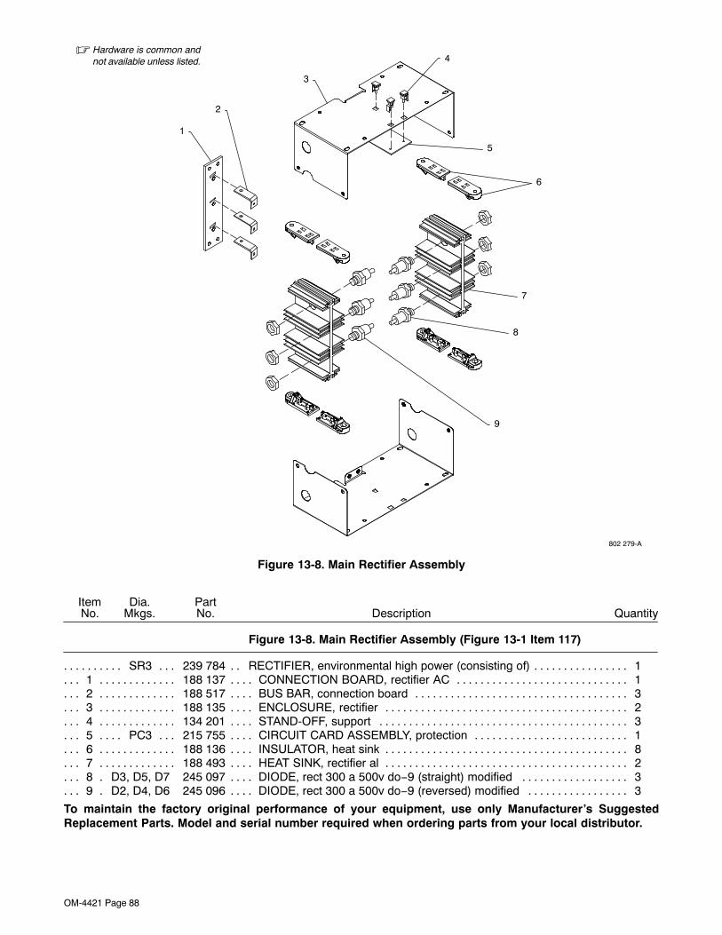
OM-4421 Page 88
� Hardware is common andnot available unless listed.
802 279-A
1
2
3
4
6
5
7
8
9
Figure 13-8. Main Rectifier Assembly
DescriptionPartNo.
Dia.Mkgs.
ItemNo.
Figure 13-8. Main Rectifier Assembly (Figure 13-1 Item 117)
Quantity
SR3 239 784 RECTIFIER, environmental high power (consisting of) 1. . . . . . . . . . . . . . . . . . . . . . . . . . . . . . .1 188 137 CONNECTION BOARD, rectifier AC 1. . . . . . . . . . . . . . . . . . . . . . . . . . . . . . . . . . . . . . . . . . . . . . . . .2 188 517 BUS BAR, connection board 3. . . . . . . . . . . . . . . . . . . . . . . . . . . . . . . . . . . . . . . . . . . . . . . . . . . . . . . .3 188 135 ENCLOSURE, rectifier 2. . . . . . . . . . . . . . . . . . . . . . . . . . . . . . . . . . . . . . . . . . . . . . . . . . . . . . . . . . . . .4 134 201 STAND-OFF, support 3. . . . . . . . . . . . . . . . . . . . . . . . . . . . . . . . . . . . . . . . . . . . . . . . . . . . . . . . . . . . . .5 PC3 215 755 CIRCUIT CARD ASSEMBLY, protection 1. . . . . . . . . . . . . . . . . . . . . . . . . . . . . . . . . . . . . . . .6 188 136 INSULATOR, heat sink 8. . . . . . . . . . . . . . . . . . . . . . . . . . . . . . . . . . . . . . . . . . . . . . . . . . . . . . . . . . . . .7 188 493 HEAT SINK, rectifier al 2. . . . . . . . . . . . . . . . . . . . . . . . . . . . . . . . . . . . . . . . . . . . . . . . . . . . . . . . . . . . .8 D3, D5, D7 245 097 DIODE, rect 300 a 500v do−9 (straight) modified 3. . . . . . . . . . . . . . . . . . . . . . . . . .9 D2, D4, D6 245 096 DIODE, rect 300 a 500v do−9 (reversed) modified 3. . . . . . . . . . . . . . . . . . . . . . . . .
To maintain the factory original performance of your equipment, use only Manufacturer’s SuggestedReplacement Parts. Model and serial number required when ordering parts from your local distributor.
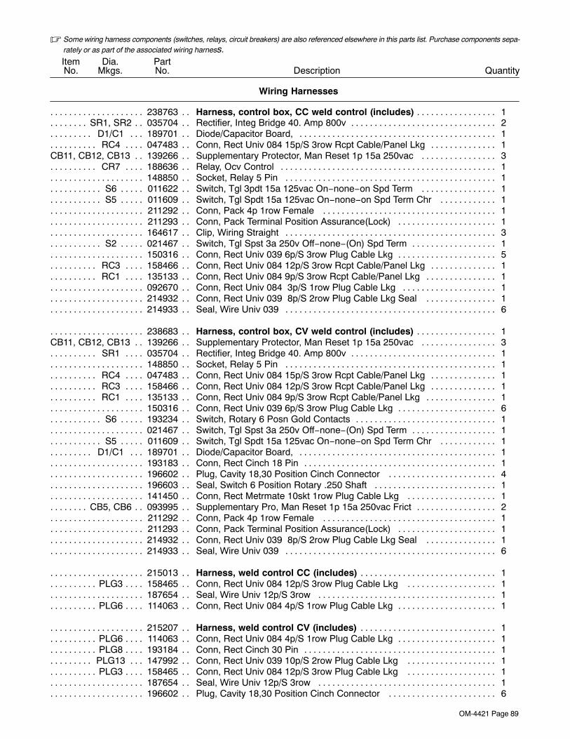
OM-4421 Page 89
� Some wiring harness components (switches, relays, circuit breakers) are also referenced elsewhere in this parts list. Purchase components sepa-rately or as part of the associated wiring harness.
DescriptionPartNo.
Dia.Mkgs.
ItemNo.
Wiring Harnesses
Quantity
238763 Harness, control box, CC weld control (includes) 1. . . . . . . . . . . . . . . . . . . . . . . . . . . . . . . . . . . . . . .SR1, SR2 035704 Rectifier, Integ Bridge 40. Amp 800v 2. . . . . . . . . . . . . . . . . . . . . . . . . . . . . . . . . . . . . . . . . . .
D1/C1 189701 Diode/Capacitor Board, 1. . . . . . . . . . . . . . . . . . . . . . . . . . . . . . . . . . . . . . . . . . . . . . . . . . . . . . . .RC4 047483 Conn, Rect Univ 084 15p/S 3row Rcpt Cable/Panel Lkg 1. . . . . . . . . . . . . . . . . . . . . . . . . . . . . .
CB11, CB12, CB13 139266 Supplementary Protector, Man Reset 1p 15a 250vac 3. . . . . . . . . . . . . . . . . . . .CR7 188636 Relay, Ocv Control 1. . . . . . . . . . . . . . . . . . . . . . . . . . . . . . . . . . . . . . . . . . . . . . . . . . . . . . . . . . . . . .
148850 Socket, Relay 5 Pin 1. . . . . . . . . . . . . . . . . . . . . . . . . . . . . . . . . . . . . . . . . . . . . . . . . . . . . . . . . . . . . . . . . . .S6 011622 Switch, Tgl 3pdt 15a 125vac On−none−on Spd Term 1. . . . . . . . . . . . . . . . . . . . . . . . . . . . . . . . . .S5 011609 Switch, Tgl Spdt 15a 125vac On−none−on Spd Term Chr 1. . . . . . . . . . . . . . . . . . . . . . . . . . . . . .
211292 Conn, Pack 4p 1row Female 1. . . . . . . . . . . . . . . . . . . . . . . . . . . . . . . . . . . . . . . . . . . . . . . . . . . . . . . . . . .211293 Conn, Pack Terminal Position Assurance(Lock) 1. . . . . . . . . . . . . . . . . . . . . . . . . . . . . . . . . . . . . . . . . . .164617 Clip, Wiring Straight 3. . . . . . . . . . . . . . . . . . . . . . . . . . . . . . . . . . . . . . . . . . . . . . . . . . . . . . . . . . . . . . . . . . .
S2 021467 Switch, Tgl Spst 3a 250v Off−none−(On) Spd Term 1. . . . . . . . . . . . . . . . . . . . . . . . . . . . . . . . . . . .150316 Conn, Rect Univ 039 6p/S 3row Plug Cable Lkg 5. . . . . . . . . . . . . . . . . . . . . . . . . . . . . . . . . . . . . . . . . . .
RC3 158466 Conn, Rect Univ 084 12p/S 3row Rcpt Cable/Panel Lkg 1. . . . . . . . . . . . . . . . . . . . . . . . . . . . . .RC1 135133 Conn, Rect Univ 084 9p/S 3row Rcpt Cable/Panel Lkg 1. . . . . . . . . . . . . . . . . . . . . . . . . . . . . . .
092670 Conn, Rect Univ 084 3p/S 1row Plug Cable Lkg 1. . . . . . . . . . . . . . . . . . . . . . . . . . . . . . . . . . . . . . . . . .214932 Conn, Rect Univ 039 8p/S 2row Plug Cable Lkg Seal 1. . . . . . . . . . . . . . . . . . . . . . . . . . . . . . . . . . . . .214933 Seal, Wire Univ 039 6. . . . . . . . . . . . . . . . . . . . . . . . . . . . . . . . . . . . . . . . . . . . . . . . . . . . . . . . . . . . . . . . . . .
238683 Harness, control box, CV weld control (includes) 1. . . . . . . . . . . . . . . . . . . . . . . . . . . . . . . . . . . . . . .CB11, CB12, CB13 139266 Supplementary Protector, Man Reset 1p 15a 250vac 3. . . . . . . . . . . . . . . . . . . .
SR1 035704 Rectifier, Integ Bridge 40. Amp 800v 1. . . . . . . . . . . . . . . . . . . . . . . . . . . . . . . . . . . . . . . . . . . . . . .148850 Socket, Relay 5 Pin 1. . . . . . . . . . . . . . . . . . . . . . . . . . . . . . . . . . . . . . . . . . . . . . . . . . . . . . . . . . . . . . . . . . .
RC4 047483 Conn, Rect Univ 084 15p/S 3row Rcpt Cable/Panel Lkg 1. . . . . . . . . . . . . . . . . . . . . . . . . . . . . .RC3 158466 Conn, Rect Univ 084 12p/S 3row Rcpt Cable/Panel Lkg 1. . . . . . . . . . . . . . . . . . . . . . . . . . . . . .RC1 135133 Conn, Rect Univ 084 9p/S 3row Rcpt Cable/Panel Lkg 1. . . . . . . . . . . . . . . . . . . . . . . . . . . . . . .
150316 Conn, Rect Univ 039 6p/S 3row Plug Cable Lkg 6. . . . . . . . . . . . . . . . . . . . . . . . . . . . . . . . . . . . . . . . . . .S6 193234 Switch, Rotary 6 Posn Gold Contacts 1. . . . . . . . . . . . . . . . . . . . . . . . . . . . . . . . . . . . . . . . . . . . . . . .
021467 Switch, Tgl Spst 3a 250v Off−none−(On) Spd Term 1. . . . . . . . . . . . . . . . . . . . . . . . . . . . . . . . . . . . . . . .S5 011609 Switch, Tgl Spdt 15a 125vac On−none−on Spd Term Chr 1. . . . . . . . . . . . . . . . . . . . . . . . . . . . . .
D1/C1 189701 Diode/Capacitor Board, 1. . . . . . . . . . . . . . . . . . . . . . . . . . . . . . . . . . . . . . . . . . . . . . . . . . . . . . . .193183 Conn, Rect Cinch 18 Pin 1. . . . . . . . . . . . . . . . . . . . . . . . . . . . . . . . . . . . . . . . . . . . . . . . . . . . . . . . . . . . . . .196602 Plug, Cavity 18,30 Position Cinch Connector 4. . . . . . . . . . . . . . . . . . . . . . . . . . . . . . . . . . . . . . . . . . . . .196603 Seal, Switch 6 Position Rotary .250 Shaft 1. . . . . . . . . . . . . . . . . . . . . . . . . . . . . . . . . . . . . . . . . . . . . . . .141450 Conn, Rect Metrmate 10skt 1row Plug Cable Lkg 1. . . . . . . . . . . . . . . . . . . . . . . . . . . . . . . . . . . . . . . . .
CB5, CB6 093995 Supplementary Pro, Man Reset 1p 15a 250vac Frict 2. . . . . . . . . . . . . . . . . . . . . . . . . . . . .211292 Conn, Pack 4p 1row Female 1. . . . . . . . . . . . . . . . . . . . . . . . . . . . . . . . . . . . . . . . . . . . . . . . . . . . . . . . . . .211293 Conn, Pack Terminal Position Assurance(Lock) 1. . . . . . . . . . . . . . . . . . . . . . . . . . . . . . . . . . . . . . . . . . .214932 Conn, Rect Univ 039 8p/S 2row Plug Cable Lkg Seal 1. . . . . . . . . . . . . . . . . . . . . . . . . . . . . . . . . . . . .214933 Seal, Wire Univ 039 6. . . . . . . . . . . . . . . . . . . . . . . . . . . . . . . . . . . . . . . . . . . . . . . . . . . . . . . . . . . . . . . . . . .
215013 Harness, weld control CC (includes) 1. . . . . . . . . . . . . . . . . . . . . . . . . . . . . . . . . . . . . . . . . . . . . . . . . . .PLG3 158465 Conn, Rect Univ 084 12p/S 3row Plug Cable Lkg 1. . . . . . . . . . . . . . . . . . . . . . . . . . . . . . . . . . .
187654 Seal, Wire Univ 12p/S 3row 1. . . . . . . . . . . . . . . . . . . . . . . . . . . . . . . . . . . . . . . . . . . . . . . . . . . . . . . . . . . .PLG6 114063 Conn, Rect Univ 084 4p/S 1row Plug Cable Lkg 1. . . . . . . . . . . . . . . . . . . . . . . . . . . . . . . . . . . . .
215207 Harness, weld control CV (includes) 1. . . . . . . . . . . . . . . . . . . . . . . . . . . . . . . . . . . . . . . . . . . . . . . . . . .PLG6 114063 Conn, Rect Univ 084 4p/S 1row Plug Cable Lkg 1. . . . . . . . . . . . . . . . . . . . . . . . . . . . . . . . . . . . .PLG8 193184 Conn, Rect Cinch 30 Pin 1. . . . . . . . . . . . . . . . . . . . . . . . . . . . . . . . . . . . . . . . . . . . . . . . . . . . . . . . .
PLG13 147992 Conn, Rect Univ 039 10p/S 2row Plug Cable Lkg 1. . . . . . . . . . . . . . . . . . . . . . . . . . . . . . . . .PLG3 158465 Conn, Rect Univ 084 12p/S 3row Plug Cable Lkg 1. . . . . . . . . . . . . . . . . . . . . . . . . . . . . . . . . . .
187654 Seal, Wire Univ 12p/S 3row 1. . . . . . . . . . . . . . . . . . . . . . . . . . . . . . . . . . . . . . . . . . . . . . . . . . . . . . . . . . . .196602 Plug, Cavity 18,30 Position Cinch Connector 6. . . . . . . . . . . . . . . . . . . . . . . . . . . . . . . . . . . . . . . . . . . . .
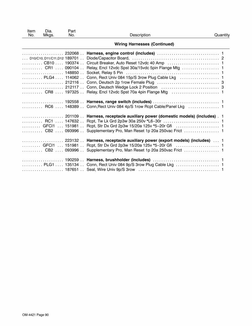
OM-4421 Page 90
DescriptionPartNo.
Dia.Mkgs.
ItemNo.
Wiring Harnesses (Continued)
Quantity
232068 Harness, engine control (includes) 1. . . . . . . . . . . . . . . . . . . . . . . . . . . . . . . . . . . . . . . . . . . . . . . . . . . .D10/C10, D11/C11,D12 189701 Diode/Capacitor Board, 2. . . . . . . . . . . . . . . . . . . . . . . . . . . . . . . . . . . . . . . . . . . . . . .
CB10 190374 Circuit Breaker, Auto Reset 12vdc 40 Amp 1. . . . . . . . . . . . . . . . . . . . . . . . . . . . . . . . . . . . . . . . .CR1 090104 Relay, Encl 12vdc Spst 30a/15vdc 5pin Flange Mtg 1. . . . . . . . . . . . . . . . . . . . . . . . . . . . . . . . . .
148850 Socket, Relay 5 Pin 1. . . . . . . . . . . . . . . . . . . . . . . . . . . . . . . . . . . . . . . . . . . . . . . . . . . . . . . . . . . . . . . . . . .PLG4 114062 Conn, Rect Univ 084 15p/S 3row Plug Cable Lkg 1. . . . . . . . . . . . . . . . . . . . . . . . . . . . . . . . . . .
212116 Conn, Deutsch 2p 1row Female Plug 3. . . . . . . . . . . . . . . . . . . . . . . . . . . . . . . . . . . . . . . . . . . . . . . . . . . .212117 Conn, Deutsch Wedge Lock 2 Position 3. . . . . . . . . . . . . . . . . . . . . . . . . . . . . . . . . . . . . . . . . . . . . . . . . .
CR8 197325 Relay, Encl 12vdc Spst 70a 4pin Flange Mtg 1. . . . . . . . . . . . . . . . . . . . . . . . . . . . . . . . . . . . . . .
192558 Harness, range switch (includes) 1. . . . . . . . . . . . . . . . . . . . . . . . . . . . . . . . . . . . . . . . . . . . . . . . . . . . . .RC6 148389 Conn,Rect Univ 084 4p/S 1row Rcpt Cable/Panel Lkg 1. . . . . . . . . . . . . . . . . . . . . . . . . . . . . . .
201109 Harness, receptacle auxiliary power (domestic models) (includes) 1. . . . . . . . . . . . . . . . . . . . . . .RC1 147632 Rcpt, Tw Lk Grd 2p3w 30a 250v *L6−30r 1. . . . . . . . . . . . . . . . . . . . . . . . . . . . . . . . . . . . . . . . . . .
GFCI1 151981 Rcpt, Str Dx Grd 2p3w 15/20a 125v *5−20r Gfi 1. . . . . . . . . . . . . . . . . . . . . . . . . . . . . . . . . . .CB2 093996 Supplementary Pro, Man Reset 1p 20a 250vac Frict 1. . . . . . . . . . . . . . . . . . . . . . . . . . . . . . . . .
223132 Harness, receptacle auxiliary power (export models) (includes) 1. . . . . . . . . . . . . . . . . . . . . . . . .GFCI1 151981 Rcpt, Str Dx Grd 2p3w 15/20a 125v *5−20r Gfi 1. . . . . . . . . . . . . . . . . . . . . . . . . . . . . . . . . . .CB2 093996 Supplementary Pro, Man Reset 1p 20a 250vac Frict 1. . . . . . . . . . . . . . . . . . . . . . . . . . . . . . . . .
190259 Harness, brushholder (includes) 1. . . . . . . . . . . . . . . . . . . . . . . . . . . . . . . . . . . . . . . . . . . . . . . . . . . . . .PLG1 135134 Conn, Rect Univ 084 9p/S 3row Plug Cable Lkg 1. . . . . . . . . . . . . . . . . . . . . . . . . . . . . . . . . . . . .
187651 Seal, Wire Univ 9p/S 3row 1. . . . . . . . . . . . . . . . . . . . . . . . . . . . . . . . . . . . . . . . . . . . . . . . . . . . . . . . . . . . .
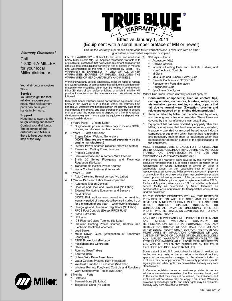
Warranty Questions?
Call1-800-4-A-MILLERfor your localMiller distributor.
miller_warr 2011−01
Your distributor also givesyou ...
ServiceYou always get the fast,reliable response youneed. Most replacementparts can be in yourhands in 24 hours.
SupportNeed fast answers to thetough welding questions?Contact your distributor.The expertise of thedistributor and Miller isthere to help you, everystep of the way.
Effective January 1, 2011(Equipment with a serial number preface of MB or newer)This limited warranty supersedes all previous Miller warranties and is exclusive with no other
guarantees or warranties expressed or implied.LIMITED WARRANTY − Subject to the terms and conditionsbelow, Miller Electric Mfg. Co., Appleton, Wisconsin, warrants to itsoriginal retail purchaser that new Miller equipment sold after theeffective date of this limited warranty is free of defects in materialand workmanship at the time it is shipped by Miller. THISWARRANTY IS EXPRESSLY IN LIEU OF ALL OTHERWARRANTIES, EXPRESS OR IMPLIED, INCLUDING THEWARRANTIES OF MERCHANTABILITY AND FITNESS.
Within the warranty periods listed below, Miller will repair or replaceany warranted parts or components that fail due to such defects inmaterial or workmanship. Miller must be notified in writing withinthirty (30) days of such defect or failure, at which time Miller willprovide instructions on the warranty claim procedures to befollowed.
Miller shall honor warranty claims on warranted equipment listedbelow in the event of such a failure within the warranty timeperiods. All warranty time periods start on the delivery date of theequipment to the original end-user purchaser, and not to exceedone year after the equipment is shipped to a North Americandistributor or eighteen months after the equipment is shipped to anInternational distributor.
1. 5 Years Parts — 3 Years Labor* Original main power rectifiers only to include SCRs,
diodes, and discrete rectifier modules2. 3 Years — Parts and Labor
* Engine Driven Welding Generators(NOTE: Engines are warranted separately by theengine manufacturer.)
* Inverter Power Sources (Unless Otherwise Stated)* Plasma Arc Cutting Power Sources* Process Controllers* Semi-Automatic and Automatic Wire Feeders* Smith 30 Series Flowgauge and Flowmeter
Regulators (No Labor)* Transformer/Rectifier Power Sources* Water Coolant Systems (Integrated)
3. 2 Years — Parts* Auto-Darkening Helmet Lenses (No Labor)
4. 1 Year — Parts and Labor Unless Specified* Automatic Motion Devices* CoolBelt and CoolBand Blower Unit (No Labor)* External Monitoring Equipment and Sensors* Field Options
(NOTE: Field options are covered for the remainingwarranty period of the product they are installed in, orfor a minimum of one year — whichever is greater.)
* Flowgauge and Flowmeter Regulators (No Labor)* RFCS Foot Controls (Except RFCS-RJ45)* Fume Extractors* HF Units* ICE Plasma Cutting Torches (No Labor)* Induction Heating Power Sources, Coolers, and
Electronic Controls/Recorders* Load Banks* Motor Driven Guns (w/exception of Spoolmate
Spoolguns)* PAPR Blower Unit (No Labor)* Positioners and Controllers* Racks* Running Gear/Trailers* Spot Welders* Subarc Wire Drive Assemblies* Water Coolant Systems (Non-Integrated)* Weldcraft-Branded TIG Torches (No Labor)* Wireless Remote Foot/Hand Controls and Receivers* Work Stations/Weld Tables (No Labor)
5. 6 Months — Parts* Batteries* Bernard Guns (No Labor)* Tregaskiss Guns (No Labor)
6. 90 Days — Parts* Accessory (Kits)* Canvas Covers* Induction Heating Coils and Blankets, Cables, and
Non-Electronic Controls* M-Guns* MIG Guns and Subarc (SAW) Guns* Remote Controls and RFCS-RJ45* Replacement Parts (No labor)* Roughneck Guns* Spoolmate Spoolguns
Miller’s True Blue® Limited Warranty shall not apply to:
1. Consumable components; such as contact tips,cutting nozzles, contactors, brushes, relays, workstation table tops and welding curtains, or parts thatfail due to normal wear. (Exception: brushes andrelays are covered on all engine-driven products.)
2. Items furnished by Miller, but manufactured by others,such as engines or trade accessories. These items arecovered by the manufacturer’s warranty, if any.
3. Equipment that has been modified by any party other thanMiller, or equipment that has been improperly installed,improperly operated or misused based upon industrystandards, or equipment which has not had reasonableand necessary maintenance, or equipment which hasbeen used for operation outside of the specifications forthe equipment.
MILLER PRODUCTS ARE INTENDED FOR PURCHASE ANDUSE BY COMMERCIAL/INDUSTRIAL USERS AND PERSONSTRAINED AND EXPERIENCED IN THE USE ANDMAINTENANCE OF WELDING EQUIPMENT.
In the event of a warranty claim covered by this warranty, theexclusive remedies shall be, at Miller’s option: (1) repair; or (2)replacement; or, where authorized in writing by Miller inappropriate cases, (3) the reasonable cost of repair orreplacement at an authorized Miller service station; or (4) paymentof or credit for the purchase price (less reasonable depreciationbased upon actual use) upon return of the goods at customer’s riskand expense. Miller’s option of repair or replacement will be F.O.B.,Factory at Appleton, Wisconsin, or F.O.B. at a Miller authorizedservice facility as determined by Miller. Therefore nocompensation or reimbursement for transportation costs of anykind will be allowed.
TO THE EXTENT PERMITTED BY LAW, THE REMEDIESPROVIDED HEREIN ARE THE SOLE AND EXCLUSIVEREMEDIES. IN NO EVENT SHALL MILLER BE LIABLE FORDIRECT, INDIRECT, SPECIAL, INCIDENTAL ORCONSEQUENTIAL DAMAGES (INCLUDING LOSS OFPROFIT), WHETHER BASED ON CONTRACT, TORT OR ANYOTHER LEGAL THEORY.
ANY EXPRESS WARRANTY NOT PROVIDED HEREIN ANDANY IMPLIED WARRANTY, GUARANTY ORREPRESENTATION AS TO PERFORMANCE, AND ANYREMEDY FOR BREACH OF CONTRACT TORT OR ANYOTHER LEGAL THEORY WHICH, BUT FOR THIS PROVISION,MIGHT ARISE BY IMPLICATION, OPERATION OF LAW,CUSTOM OF TRADE OR COURSE OF DEALING, INCLUDINGANY IMPLIED WARRANTY OF MERCHANTABILITY ORFITNESS FOR PARTICULAR PURPOSE, WITH RESPECT TOANY AND ALL EQUIPMENT FURNISHED BY MILLER ISEXCLUDED AND DISCLAIMED BY MILLER.
Some states in the U.S.A. do not allow limitations of how long animplied warranty lasts, or the exclusion of incidental, indirect,special or consequential damages, so the above limitation orexclusion may not apply to you. This warranty provides specificlegal rights, and other rights may be available, but may vary fromstate to state.
In Canada, legislation in some provinces provides for certainadditional warranties or remedies other than as stated herein, andto the extent that they may not be waived, the limitations andexclusions set out above may not apply. This Limited Warrantyprovides specific legal rights, and other rights may be available,but may vary from province to province.

ORIGINAL INSTRUCTIONS − PRINTED IN USA © 2011 Miller Electric Mfg. Co. 2011−01
Miller Electric Mfg. Co.An Illinois Tool Works Company1635 West Spencer StreetAppleton, WI 54914 USA
International Headquarters−USAUSA Phone: 920-735-4505 Auto-AttendedUSA & Canada FAX: 920-735-4134International FAX: 920-735-4125
For International Locations Visitwww.MillerWelds.com
Model Name Serial/Style Number
Purchase Date (Date which equipment was delivered to original customer.)
Distributor
Address
City
State Zip
Please complete and retain with your personal records.
Always provide Model Name and Serial/Style Number.
Contact a DISTRIBUTOR or SERVICE AGENCY near you.
Welding Supplies and Consumables
Options and Accessories
Personal Safety Equipment
Service and Repair
Replacement Parts
Training (Schools, Videos, Books)
Technical Manuals (Servicing Informationand Parts)
Circuit Diagrams
Welding Process Handbooks
Contact the Delivering Carrier to:
For Service
Owner’s Record
File a claim for loss or damage duringshipment.
For assistance in filing or settling claims, contactyour distributor and/or equipment manufacturer’sTransportation Department.
Contact your Distributor for:
To locate a Distributor or Service Agency visitwww.millerwelds.com or call 1-800-4-A-Miller