
Bidirectional syngas generator TSW work on advanced large scale non steady state reactor
8
See discussions, stats, and author profiles for this publication at: http://www.researchgate.net/publication/222015257 Bi-Directional Adiabatic Synthesis Gas Generator ARTICLE in CHEMICAL ENGINEERING SCIENCE · DECEMBER 1990 Impact Factor: 2.34 · DOI: 10.1016/0009-2509(90)80122-U CITATIONS 91 READS 27 3 AUTHORS, INCLUDING: Steve Wittrig California Institute of Technology 18 PUBLICATIONS 300 CITATIONS SEE PROFILE David Peterson BP plc 9 PUBLICATIONS 94 CITATIONS SEE PROFILE Available from: Steve Wittrig Retrieved on: 08 October 2015
-
Upload
steve-wittrig -
Category
Engineering
-
view
77 -
download
0
Transcript of Bidirectional syngas generator TSW work on advanced large scale non steady state reactor

Seediscussions,stats,andauthorprofilesforthispublicationat:http://www.researchgate.net/publication/222015257
Bi-DirectionalAdiabaticSynthesisGasGenerator
ARTICLEinCHEMICALENGINEERINGSCIENCE·DECEMBER1990
ImpactFactor:2.34·DOI:10.1016/0009-2509(90)80122-U
CITATIONS
91
READS
27
3AUTHORS,INCLUDING:
SteveWittrig
CaliforniaInstituteofTechnology
18PUBLICATIONS300CITATIONS
SEEPROFILE
DavidPeterson
BPplc
9PUBLICATIONS94CITATIONS
SEEPROFILE
Availablefrom:SteveWittrig
Retrievedon:08October2015

Chemical Engineering Science, Vol. 45, No. 8, pp. 2407-2413, 1990 Printed in Great Britain.
CW!-2509/90 $3.00 + 0.00 0 1990 Pergamon Press plc
BIDIRECTIONAL ADIABATIC SYNTHESIS GAS GENERATOR
R. F. Blanks, T. S. Wittrig. D. A. Peterson
Amoco Chemical Research and Development P. 0. Box 3011, Naperville, IL 60566
ABSTRACT
This paper describes a unique reactor for the production of synthesis gas, carbon monoxide and hydrogen, from the catalytic partial oxidation of natural gas with air. The reactor operates near atmospheric pressure with nickel on alumina catalyst at about 8OO'C. The product synthesis gas has a hydrogen to carbon monoxfde mole ratio near two, which is ideal for feed to a Fischer-Tropsch conversion reactor. The reactor operates adiabatically and autothermally, requiring no additional energy for operation other than the exothermic heat of reaction. Waste heat is efficiently recovered using packed bed heat exchangers. Problems of coke formation are effectively eliminated. The two packed beds are situated in the reactor above and below the catalyst bed. The reactor operates in an unsteady-state mode with feed and product gas flow directions periodically reversed. The reactor was tested experimentally on a laboratory scale unit processing about three liters per minute of natural gas and on a large pilot plant processing about 1400 cubic meters per day of natural gas. A mathematical and computer simulation model was developed to describe the reactor and its operation.
KEYWORDS
Synthesis Gas, Natural Gas, Reactor, Oxidation, Simulation
INTRODUCTION
The chemical industry is engaged in research to develop improved economics of processes to convert natural gas to transportable liquid fuels. One route under study is the synthesis of paraffinic hydrocarbons from natural gas-derived synthesis gas. The chemistry of producing
synthesis gas from natural gas by catalytic partial oxidation is well known. World scale
plants of this type exist. The reactions describing the process follow.
1. Methane combustion
CH4 + l/2 O2 + 1.881 N2 - 3/4 CH4 + l/4 COP t l/2 Hz0 + 1.881 N2 ;ya==-z’1”6”,‘$a’
2. & 3. Steam reforming and COP reforming combined
3,‘4 CH., + l/2 Hz0 + l/4 COP + 1.88 N2 - CO + 2H2 + 1.88 N2 ;;~=+_;;;;~~d”’
4. Water gas shift reaction
CO+H20-,C02+H2
Only three of these reactions are required to describe the state of the system. Synthesis gas generators operate very close to thermodynamic equilibrrum. Product composition and carbon monoxide yield can be calculated from a knowledge of process temperature, pressure, and feed
composition. A complication arises due to the formation of solid carbon, coke, at certain
conditions. If the feed composition has an oxygen to carbon mole ratio less than 0.52, or if
the bed temperature is below 700-C, solid carbon forms at equilibrium. On the other hand, catalyst bed temperature should be above 8OO'C to obtain good yields of carbon monoxide by
catalytic partial oxidation. The reactor engineering design issues are defined by these
factors. In an attempt to address these issues, we developed a unique synthesis gas
generation reactor, based on catalytic partial oxidation. Fig. 1.
2407
2408 R.F. BLANKS~~ ai. Dl
Natural Q-
Air
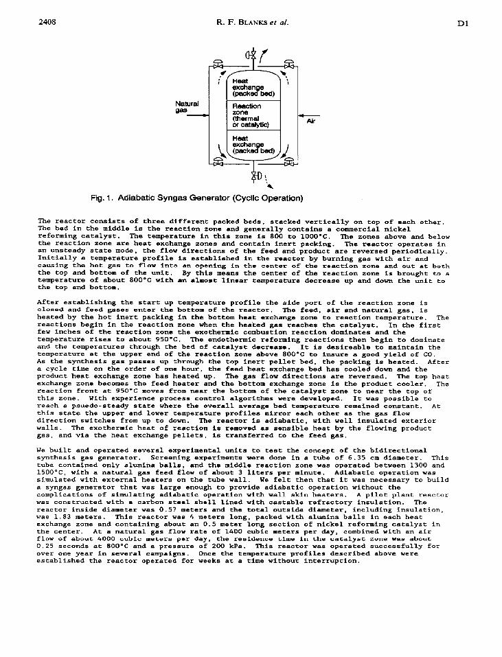
Fig. 1. Adiabatic Syngas Generator (Cyclic Operation)
The reactor consists of three different packed beds, stacked vertically on top of each other. The bed in the middle is the reaction zone and generally contains a commercial nickel reforming catalyst. The temperature in this zone is 800 to 1OOO'C. The zones above and below the reaction zone are heat exchange zones and contain inert packing. The reactor operates in an unsteady state mode. the flow directions of the feed and product are reversed periodically. Initially a temperature profile is established in the reactor by burning gas with air and causing the hot gas to flow into an opening in the center of the reaction zone and out at both the top and bottom of the unit. By this means the center of the reaction zone is brought to a temperature of about 800-C with an almost linear temperature decrease up and down the unit to the top and bottom.
After establishing the start up temperature profile the side port of the reaction zone is closed and feed gases enter the bottom of the reactor. The feed, air and natural gas, is
heated by the hot inert packing in the bottom heat exchange zone to reaction temperature. The
reactions begin in the reaction zone when the heated gas reaches the catalyst. In the first few inches of the reaction zone the exothermic combustion reactfon dominates and the temperature rises to about 95O'C. The endothermic reforming reactions then begin to dominate and the temperatures through the bed of catalyst decrease. It is desireable to maintain the temperature at the upper end of the reaction zone above 8OO'C to insure a good yield of CO. As the synthesis gas passes up through the top inert pellet bed, the packing is heated. After
a cycle time on the order of one hour, the feed heat exchange bed has cooled down and the product heat exchange zone has heated up. The gas flow directions are reversed. The top heat exchange zone becomes the feed heater and the bottom exchange zone is the product cooler. The reaction front at 950-C moves from near the bottom of the catalyst zone to near the top of this zone. With experience process control algorithms were developed. It was possible to
reach a psuedo-steady state where the overall average bed temperature remained constant. At th1.s state the upper and lower temperature profiles mirror each other as the gas flow direction switches from up to down. The reactor is adiabatic, with well insulated exterior
walls. The exothermic heat of reaction is removed es sensible heat by the flowing product
gas. and via the heat exchange pellets, is transferred to the feed gas.
We built and operated several experimental units to test the concept of the bidirectional synthesis gas generator. Screening experiments were done in a tube of 6.35 cm diameter. This
tube contained only alumina balls, and the middle reaction zone was operated between 1300 and
15OO"C, with a natural gas feed flow of about 3 liters par minute. Adiabatic operation was simulated with external heaters on the tube wall. We felt then that it was necessary to build a syngas generator that was large enough to provide adiabatic operation without the complications of simulating adiabatic operation with wall skin heaters. A pilot plant reactor
was constructed with a carbon steel shell lined with castable refractory insulation. The reactor inside diameter was 0.57 meters and the total outside diameter, including insulation, was 1.83 meters. This reactor wa8 4 meters long, packed with alumina balls in each heat exchange zone and containing about an 0.5 meter long section of nickel reforming catalyst in the center. At a natural gas flow rate of 1400 cubic meters per day, combined with an air flow of about 4000 cubic meters par day, the residence time in thha catalyst zone was about 0.25 seconds at 800°C and a pressure of 200 kPa. This reactor was operated successfully for over one year in several campaigns. Once the temperature profiles described above were
established the reactor operated for weeks at a time without interruption.

Dl Bidirectional adiabatic synthesis gas generator 2409
MATHEMATICAL AND COMPUTER MODEL OF THE CXNERATOR
The essential features of the bidirectional, adiabatic, ayngas generator are described by the following partial differential and algebraic equations.
Synthesis Gas Generator Mathematical Model
1. Fluid phase energy balance
2. Solid phase energy balance
dT,= K, d*T, - ha(T,-Tf) 1
Jt (l-E)P& J x2 (WPIICg - (1 -sk*c, 7 *HI RI
3-6. Component mass balances (02, CH b CO*, H 20)
dyl= VJY, + MW - - dt Jx PfE
El cl Ri
Syngas Generator Model - Kinetic Equations
1. Reaction 1 - Combustion
Rl = Al l exp(-El/RT, (x, t)) l (y02* yCH4) Hl = -172260 BTU/(Mol 02)
2. Reaction 2 - CO2 reforming
R2 = A2 l exp(-EYRT, (x, t)) l (yC02* yCH4) H2 = +l 11924 BTU/(Mol CH4)
3. Reactlon 3 - Steam reforming
R3 - A3 l exp(-E3/RT, (x, t)) l (yH20 l yCH,) H3 = +96966 BTU/(Mol CH4)
The above equations describe the unsteady state axial temperature change in both the gas and solid phases in the reaction or heat exchange zones, and the unsteady state change Ln gas composition. The kinetic equations describe the combustion and reforming reactions. The reactor was well insulated and measured radial temperature profiles confirmed that temperature gradients in the radial direction are small. Therefore the equations contain only one geometric dimension. We assumed plug flow through the bed and neglected axial dispersion. The total change in moles of gas caused by the reaction was neglected and average gas phase properties were used for each zone of the reactor.
The set of equations shown above was solved numerically on an Applied Dynamics, ADlOO, mulriprocessor, using a VAX host compurer. In all, the model conrains 60 input parameters. Most of these are well characterized. The twelve that could not be readily calculated from other sources were: the effective bed thermal conductivity and the convective gas-solid heat transfer coefficient for each of the three zones, and the two kinetic parameters for each of the three reactions. These parameters were estimated by a three tiered, fractional factorial fit of the model predictions to experimental data from the pilot plant.
2410 R. F. BLANKS& al. D1
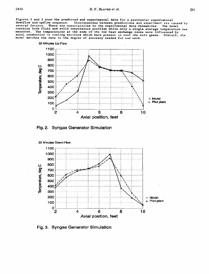
Figures 2 and 3 show the predicted and experimental data for a particular experimental
downflow and upflow sequence. several factors.
Discrepancies between predictions and experiment are caused by There are uncertainties in the experimental data themselves. The model
contains both fluid and solid temperature profiles while only a single average temperature was measured. The temperatures at the ends of the two heat exchange zones were influenced by axial conduction to cooling sections which were present to cool the exit gases. Overall. the model matches the data to the degree of accuracy needed for our work.
32 Minutes Up-Flow
1100
1000
000
0 800
g 700
- 600 s I!
500
e 400
e 300
200 i’
100 CT
0 2 4 6 6 10
Axial position, feet
Fig. 2. Syngas Generator Simulation
32 Minutes Down-Flow
0 Model + Pilot plant
1100
1000
900
0 800
_ c! 600
ff 500
2 400 c c/
e? 300
200
100
0
0 Model + Pilot plant
1
2 4 6 8 10 Axial position, feet
Fig. 3. Syngas Generator Simulation
Dl Bidirectional adiabatic synthesis gas generator
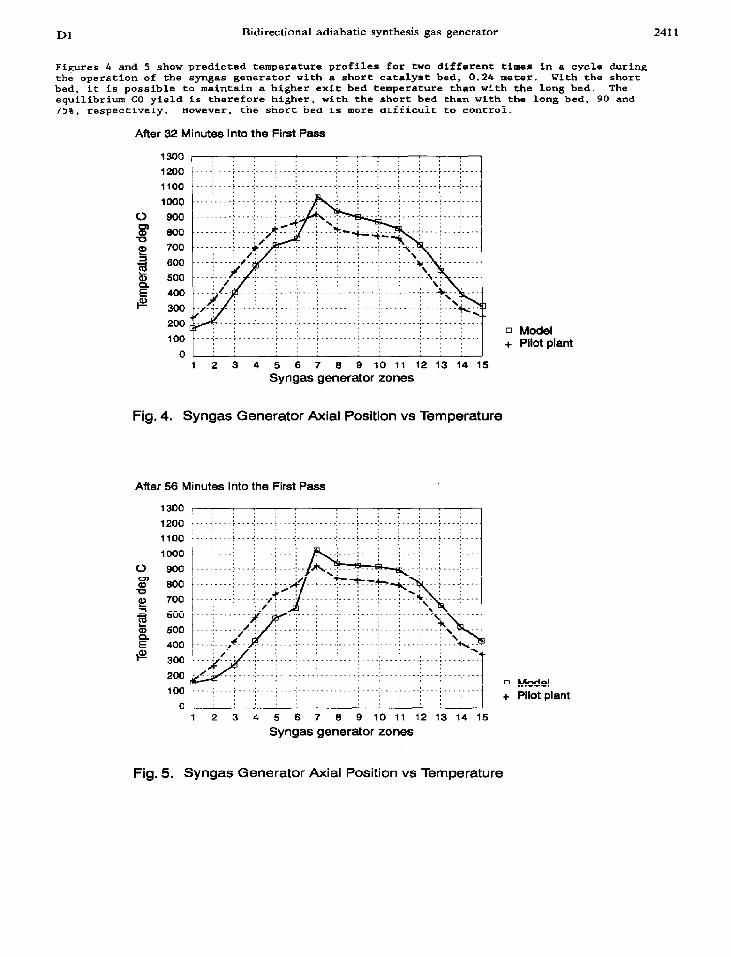
Figures 4 and 5 show predicted temperature profiles for two different times in a cycle during the operation of the syngas generator with a short catalyst bed, 0.24 meter. With the short bed, it is possible to maintain a higher exit bed temperature than with the long bed. The equilibrium CO yield is therefore higher, with the short bed than with the long bed, 90 and 75%. respectively. However, the short bed is more difficult to control.
After 32 Minutes Into the First Pass
$300 r 1200
1100
1000
0 900
8 800 -0 g! 700
g ;t
i$ 400 F 300
I 200
G3
100
0 1 2 3 4 5 6 7 6 9 1011 12131415
Syngas generator zones
: : : : : : : :
____,__.. . . . . . ..__ i_ __.:... : : :
: : : : :
. . . . . :_...:....: . . . . . ..__. :.._
0 Model + Pilot plant
Fig. 4. Syngas Generator Axial Position vs Temperature
After 56 Minutes Into the First Pass
1300
1200 1100
1000
0 900
F 800 -u E 700
f e
600 500 400
g 300
200 4 100
0 L 1 2 3 4 5 6 7 0 9 1011 12131415
Syngas generator zones
0 Model + Pilot plant
2411
Fig. 5. Syngas Generator Axial Position vs Temperature
2412 R. F. BLANKS et al.
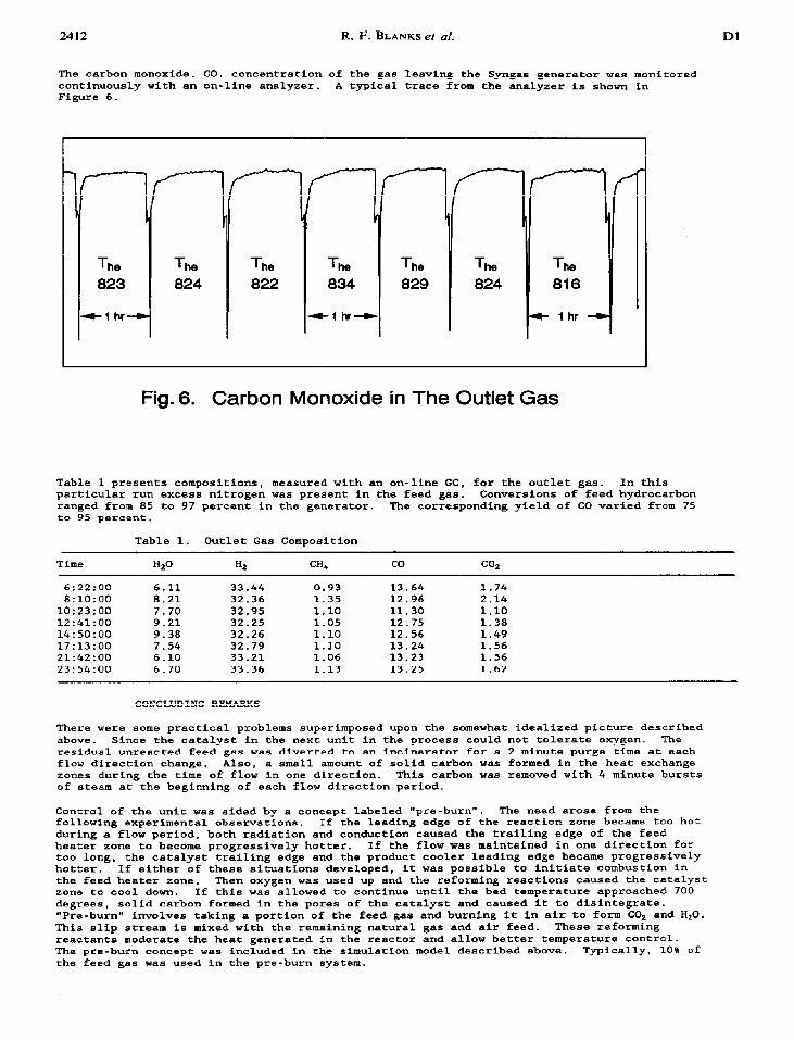
The carbon monoxide. CO, concentration of the gas leaving the Syngas generator was monitored
continuously with an on-line analyzer. A typical trace from the analyzer is shown in Figure 6.
Dl
The The 824 822
4-l hr+
The 824
Fig. 6. Carbon Monoxide in The Outlet Gas
Table 1 presents compositions, measured with an on-line GC, for the outlet gas. In this particular run excess nitrogen was present in the feed gas. Conversions of feed hydrocarbon
ranged from 85 to 97 percent in the generator. The corresponding yield of CO varied from 75 to 95 percent.
Table 1. Outlet Gas Composition
Time Hz0 HZ CH4 co CO2
6:22:00 6.11 33.44 0.93 13.64 1.74 8:lO:OO 8.21 32.36 1.35 12.96 2.14
10:23:00 7.70 32.95 1.10 11.30 1.10 12:41:00 9.21 32.25 1.05 12.75 1.38
14:50:00 9.38 32.26 1.10 12.56 1.49 17:13:00 7.54 32.79 1.10 13.24 1.56 21:42:00 6.10 33.21 1.06 13.23 1.56
23:54:00 6.70 33.36 1.13 13.25 1.62
CONCLUDING REMARKS
There were some practical problems superimposed upon the somewhat idealized picture described
above. Since the catalyst in the next unit in the process could not tolerate oxygen. The residual unreected feed gas was diverted to an inclneratar for a 2 minute purge time at each flow direction change. Also, a small amount of solid carbon was formed in the heat exchange zones during the time of flow in one direction. This carbon was removed with 4 minute bursts of steam at the beginning of each flow direction period.
Control of the unit was aided by a concept labeled "pre-burn". The need arose from the
following experimental observations. If the leading edge of the reaction zone became too hot
during a flow period. both radiation and conduction caused the trailing edge of the feed heater zone to become progressively hotter. If the flow was maIntained in one direction for
too long, the catalyst trailing edge and the product cooler leading edge became progressively hotter. If either of these situations developed, it was possible to initiate combustion in
the feed heater zone. Then oxygen was used up and the reforming reactions caused the catalyst zone to cool down. If this was allowed to continue until the bed temperature approached 700
degrees, solid carbon formed in the pores of the catalyst and caused it to disintegrate.
"Pre-burn" involves taking a portion of the feed gas and burning it in air to form CO2 and H20. This slip stream is mixed with the remaining natural gas and air feed. These reforming
reactants moderate the heat generated in the reactor and allow better temperature control. The pre-burn concept was included in the simulation model described above. Typically, 10% of
the feed gas was used in the pre-burn system.

Bidirectional adiabatic synthesis gas generator 2413
Several refinements could improve the validity of the mathematical model. Describing the
change in number of moles of the gas as the reaction proceeds allows adjustment of axial velocity in the flow direction. This effects residence time in the various zones, and the parameters in the correlations which are used to obtain bed conductivities and heat transfer
coefficients. This also effects gas physical properties and partial pressures. The thermal
conductivity of the gas changes significantly as hydrogen is produced by the reaction. The kinetic model could be refined to include the formation of solid carbon by methane pyrolysis or the Boudouard Reaction. The model could be extended by including the possibility of thermal combustion of methane in the heat transfer zones of the unit.
Nevertheless, as it stands, the model is a good representation of the performance of the bidirectional generator and is useful for design and scale up. It is also useful for
analyzing the effect of variable changes on reactor performance. The adiabatic bidirectional
synthesis gas generator is a novel and potentially low cost alternative to compare with present conventional systems.
A
a
C
E
Al3.H h
K
Mu
f;
T
NOTATION
Pre-exponential reaction rate factor Gas to solid interfacial
area, meter2/meter3 Heat capacity, J/kg*K Activation engergy. kcal/mole Heat of reaction, Kcal Gas to solid heat transfer coefficient .J/m%K Effective bed thermal I conductiving. J/m-s-K
Average molecular weight. Kg/mole Reaction rate Gas constant Temperature, 'C
AT, Adiabatic temperature rise, "C
t Time, seconds V Gas velocity, meter/set X Flow direction, meters
Y Mole fraction
Graek c Bed void fraction
P Density, kg/m'
m f Fluid phase 8 Solid phase