
BGL - Moving Bed
47
Process Engineering Division British Gas / Lurgi Gasifier IGCC Base Cases PED-IGCC-98-004 September 1998 Latest Revision June 2000
description
moving bed gasifier
Transcript of BGL - Moving Bed

Process Engineering Division
British Gas / Lurgi Gasifier IGCC Base Cases
PED-IGCC-98-004
September 1998Latest Revision June 2000

PREFACE
This report presents the results of an analysis of two British Gas/Lurgi Gasifier IGCC Base Cases. The analyses were performed by W. Shelton and J. Lyons of EG&G.
EXECUTIVE SUMMARY
1. Process Descriptions 1.1 Coal Prep / BGL Gasifier / Gas Liquor Separation
1.2 Air Separation Plant (ASU)1.3 Gas Cooling/COS Hydrolysis / Fuel Gas Saturation - Case 11.4 Cold Gas Cleanup Unit (CGCU) - Case 1
1.5 Chloride Guard Bed / Fine Particulate Removal - Case 2 1.6 Transport Desulfurization HGCU - Case 2 1.7 Sulfuric Acid Plant - Case 2 1.8 Gas Turbine
1.9 Steam Cycle1.10 Power Production
2. Simulation Development3. Cost of Electricity Analysis 3.1 Coal Handling/ Conveying/ Briquetting
3.2 Flux Receiving/Handling3.3 Oxygen Plant3.4 British Gas/ Lurgi Gasifier3.5 Low Temperature Gas Cooling/Fuel Gas Saturation and Gas Liquor Separation and
Treatment - CASE 1 only3.6 MDEA/ Claus/ SCOT Section - CASE 1 only3.7 Gas Conditioning - CASE 2 only3.8 Desulfurization Section - CASE 2 only3.9 Acid Plant Section - CASE 2 only3.10 Gas Turbine Section3.11 HRSG/Steam Turbine Section3.12 Bulk Plant Items
Appendix A COE SpreadsheetsAppendix B Modifications made to 1998 IGCC Process System Study

BRITISH GAS/ LURGI GASIFIER IGCC BASE CASE
EXECUTIVE SUMMARY
ASPEN PLUS (version 10.1) Simulation Models and the Cost of Electricity (COE) have beendeveloped for two IGCC cases based on the British Gas/ Lurgi (BGL) gasification process. Theobjective was to establish a base cases for commercially available (or nearly available) power plantsystems having a nominal size of 400 megawatts (MWe). The simulation models are based onprevious simulations (ASPEN Archive CMS Library), available literature information, and BritishGas/ Lurgi published reports. The COE estimates are based on data from the EG&G CostEstimating Notebook and several contractor reports. These cases can be used as a starting pointfor the development and analysis of proposed advanced power systems.
The cases developed have the following common process sections:& Coal Prep - separating, drying, and briquetting of fines.& BGL Gasification - oxygen-blown, moving-bed, slagging gasifier.& Air Separation Unit (ASU) - high pressure process integrated with the gas turbine.& �G� gas turbine -W501G modified for coal derived fuel gas.& Three pressure level subcritical reheat Steam Cycle - (1800 psia/1050(F/342 psia/1050(F/ 35 psia).
The approach used for gas cleanup accounts for the major differences between the two cases. Forsulfur removal, Case 1 uses cold gas cleanup (CGCU) and Case 2 uses transport desulfurizationhot gas cleanup (HGCU). In Case 1, the raw fuel gas enters a gas/liquor separation and treatmentunit where heavy hydrocarbons are removed and then is further cooled, enters a COS hydrolyzer,and is scrubbed (removes remaining particulates, ammonia and chlorides) before entering theCGCU section. In Case 2, the raw fuel gas enters a filter and a chloride guard bed prior to theHGCU section. Sulfur is recovered as elemental sulfur using the Claus process for Case 1 and assulfuric acid using an acid plant for Case 2. In Case 2, the heavy hydrocarbons remain in the fuelgas and are consumed in the gas turbine combustor.
Process flow diagrams and material and energy balances summaries are shown in Figures 1-4 andCOE summaries are given in Appendix A. In Table 1 the overall results obtained for powergeneration, process efficiency, and COE are given.

BRITISH GAS/ LURGI IGCC BASE CASES Page 2
Table 1: British Gas/ Lurgi Gasifier IGCC Base Cases Summary
CASE 1 CASE 2
Gasifier BGL BGL
Sulfur Removal CGCU HGCU
Gas Turbine Power (MWe) 272.6 272.5
Steam Turbine Power (MWe) 133.4 130.3
Misc./Ax Power (MWe) 31.1 30.7
Total Plant Power (MWe) 374.9 372.1
Efficiency, HHV (%) 45.3 49.4
Efficiency, LHV (%) 47.1 51.3
Total Capital Requirement, ($1000) 533,664 503,640
$/kW 1,423 1,354
Net Operating Costs ($1000) 46,445 40,416
COE (mills/kWh) 44.5 41.1

BRITISH GAS/ LURGI IGCC BASE CASES Page 3

BRITISH GAS/ LURGI IGCC BASE CASES Page 4
FIGURE 1B
BGL IGCC - CGCU / W501G GT
SUMMARY: POWER MWe EFFICIENCY: %
GAS TURBINE 272.6 HHV 45.3STEAM TURBINE 133.4 LHV 47MISCELLANEOUS 19.5AUXILIARY 11.6NET POWER 374.9
STREAM 1 2 3 4 5 6 7 8 9 10 11 12 13 14 15FLOW (LB/HR) 237527 178146 4228 10076 9661 9019 8841 75006 124519 446254 35011 275000 9019 712236 388896TEMPERATURE (F) 59 59 392 59 110 160 160 684 203.6 986.4 140 176 299 299 100PRESSURE (PSIA) 14.7 14.7 14.7 14.7 420 395 395 500 464.1 395 14.7 435 392 392 371H (MM BTU/HR) -281.3 -211 -1.8 -52.3 0.1 3 3.1 -413.7 3.1 -751.4 -78.5 -1858.5 3.5 -2665.1 -713.5
STREAM 16 17 18 19 20 21 22 23 24 26 30 31 32 33 34FLOW (LB/HR) 368010 7078 15010 1101 5889 29370 13172 13172 2992 2241 261884 260756 4320000 3517529 261884TEMPERATURE (F) 116 116 144.2 70 285 70 59 161.2 67.6 550.7 59 204.2 59 813.5 813.5PRESSURE (PSIA) 376 376 18.5 17.5 14.7 17.5 14.7 25 14.7 335 14.7 280.4 14.7 282.4 282.4H (MM BTU/HR) -668.1 -12.8 -37 -3.6 0.3 -73.7 -0.5 -0.2 -20.4 -3.8 -10.9 4.4 -180.3 512.2 38.1
STREAM 35 36 37 38 39 25 40 41 42 43 44 45 46 47 48FLOW (LB/HR) 261884 522639 522639 124519 126005 25654 244597 14492 137166 573255 527109 527109 4090782 4617892 71442TEMPERATURE (F) 460 333 179.4 60 62 60 62 112.8 203.8 550.7 813.5 600 2583 1124.1 59.8PRESSURE (PSIA) 280.4 280.4 280.4 92 91 265 91 425 360 335 282.4 276.8 268.5 15.2 375H (MM BTU/HR) 14.6 18.9 -0.9 -0.6 -1.4 -0.2 -2.7 0 3.3 -983.5 76.8 47.9 -510.8 -2215.5 -491.8
STREAM 49 77 78FLOW (LB/HR) 6793 70000 70000TEMPERATURE (F) 59 606.2 1055.4PRESSURE (PSIA) 14.7 350 342H (MM BTU/HR) -46.8 -388.6 -371.8

BRITISH GAS/ LURGI IGCC BASE CASES Page 5

BRITISH GAS/ LURGI IGCC BASE CASES Page 6
FIGURE 2B
BGL IGCC - CGCU / W501G GT
STEAM CYCLE / HRSG PROCESS STREAMS
STREAM 47 50 51 52 53 54 55 56 57 58 59 60 61 62 63FLOW (LB/HR) 4617892 4617892 757458 171219 201172 544214 163752 171219 171219 7467 7392 201172 201172 201172 199160TEMPERATURE (F) 1124.1 292 205 217.3 217.3 217.3 300 217.4 300 300 430 218.1 300 430 432.3PRESSURE (PSIA) 15.2 14.7 17 16.3 16.3 16.3 76.3 80.3 76.3 76.3 70.5 410.6 390 370.5 352H (MM BTU/HR) -2215.5 -3246.8 -5069.7 -1143.9 -1344 -3635.7 -1080.2 -1143.8 -1129.5 -49.3 -41.5 -1343.6 -1326.9 -1299.3 -1127.7
STREAM 64 65 66 67 68 69 70 71 72 73 74 75 76 77 78FLOW (LB/HR) 199160 544214 544214 544214 62396 481818 481818 476999 476999 62396 539396 464390 75006 70000 70000TEMPERATURE (F) 620 221.4 300 430 430 430 620 629.3 1050 1050 1049.3 606.2 695.7 606.2 1055.4PRESSURE (PSIA) 350 2345.6 2228.3 2116.9 2116.9 2116.9 2011.1 1910.5 1815 1815 1800 350 510 350 342H (MM BTU/HR) -1104.1 -3630.7 -3587.8 -3513.9 -402.9 -3111.1 -2997.6 -2729.2 -2554.6 -334.2 -2888.7 -2578.1 -413.4 -388.6 -371.8
STREAM 79 80 81 82 83 84 86 87 88 89 90 91 92 93 94FLOW (LB/HR) 5178 394390 593549 593549 663549 74421 726845 135502 135502 135502 726845 892960 892960 892960 6905TEMPERATURE (F) 820.3 606.2 610.8 1050 1050.6 598.9 430.5 205 205.1 300 88.8 87.9 87.9 205 213PRESSURE (PSIA) 150 350 350 342 342 60 35 18 75 65 0.7 0.7 18 18 15H (MM BTU/HR) -28.1 -2189.5 -3293.6 -3154.6 -3526.4 -411.9 -4081 -906.9 -906.9 -770.5 -4257.9 -6081.2 -6081.1 -5976.6 -43.4
STREAM 95 96 97 98 99 G1 G2 G3 G5 G6 G7 G8 G9FLOW (LB/HR) 166116 4606 75 2012 4818 4617892 4617892 4617892 4617892 4617892 4617892 4617892 4617892TEMPERATURE (F) 60 217.3 305.3 432.3 629.3 1124.1 880.8 690.3 578.5 447 361.2 355.5 292.7PRESSURE (PSIA) 14.7 16.3 72.5 352 1910.5 15.2 15.2 15.2 15.2 15.2 15.2 15.2 15.2H (MM BTU/HR) -1135.9 -26.3 -0.5 -13 -29.9 -2215.5 -2529.2 -2767.7 -2904.8 -3063.3 -3165.3 -3172 -3246

BRITISH GAS/ LURGI IGCC BASE CASES Page 7

BRITISH GAS/ LURGI IGCC BASE CASES Page 8
FIGURE 3B
BGL IGCC - HGCU / W501G GT
SUMMARY: POWER MWe EFFICIENCY: %
GAS TURBINE 272.5 HHV 49.4STEAM TURBINE 130.3 LHV 51.3MISCELLANEOUS 19.2AUXILIARY 11.5NET POWER 372.1
STREAM 1 2 3 4 5 6 7 8 9 10 11 15 16 17 18FLOW (LB/HR) 214558 160919 8821 9174 105509 3850 66256 6185 105509 378604 31878 377984 3744491 416055 413325TEMPERATURE (F) 59 59 120 59 60 392 700 59 203.4 973.2 140 968.8 1068 1068 1442.1PRESSURE (PSIA) 14.7 14.7 464 15 92 14.7 500 14.7 464 395 14.7 380 370 370 375H (MM BTU/HR) -244.2 -183.2 0.1 -47.6 -0.5 -1.6 -364.9 -42.6 2.6 -666.1 -71.5 -666.2 -12847.6 -1427.5 -1426
STREAM 19 20 21 22 23 24 25 26 27 28 29 3A 3B 3C V1FLOW (LB/HR) 4536020 375475 386863 11606 11606 11606 11606 2040 218 35454 35454 16559 35454 218 84786TEMPERATURE (F) 1070 1070 1065.1 1065.1 750 877.7 905.2 971.2 1065.1 190 120 120 120 100 62PRESSURE (PSIA) 375 370 360 360 350 501.2 750 294 370 277.2 272.2 464 385 380 91H (MM BTU/HR) -14940.3 -667 -687.5 -20.6 -22.2 -21.6 -21.4 -2.2 -0.9 -0.4 -1.1 0.1 -1.2 -1 -0.9
STREAM V2 30 31 32 33 34 35 36 37 38 39 40 41 42 43FLOW (LB/HR) 2536 221902 4320000 257356 3522056 257356 220960 221902 442862 21737 229237 221183 29791 221183 594400TEMPERATURE (F) 59 59 59 812.7 812.7 363 203.7 190 196.8 60 62 192.5 120 712 971.2PRESSURE (PSIA) 14.7 14.6 14.6 282.2 282.2 280.2 278 277.2 277.2 265 91 300 464 294 294H (MM BTU/HR) -17.3 -9.3 -180.3 37.5 512.9 8.1 3.6 -2.5 1.1 -0.1 -2.5 4.7 0.1 34.1 -630.6
STREAM 44 45 46 47 A1 A2 A5 A6 77 78FLOW (LB/HR) 527109 527109 4116455 4643564 54742 54742 52888 16659 70000 70000TEMPERATURE (F) 812.7 600 2583 1116.5 1442.1 850 100 100 606.2 1055.4PRESSURE (PSIA) 282.2 276.6 268.5 15.2 375 365 16 16 350 342H (MM BTU/HR) 76.8 48 -156.2 -1860.6 -4.5 -12.9 -1 -20.9 -388.6 -371.8

BRITISH GAS/ LURGI IGCC BASE CASES Page 9
BRITISH GAS/ LURGI IGCC BASE CASES Page 10
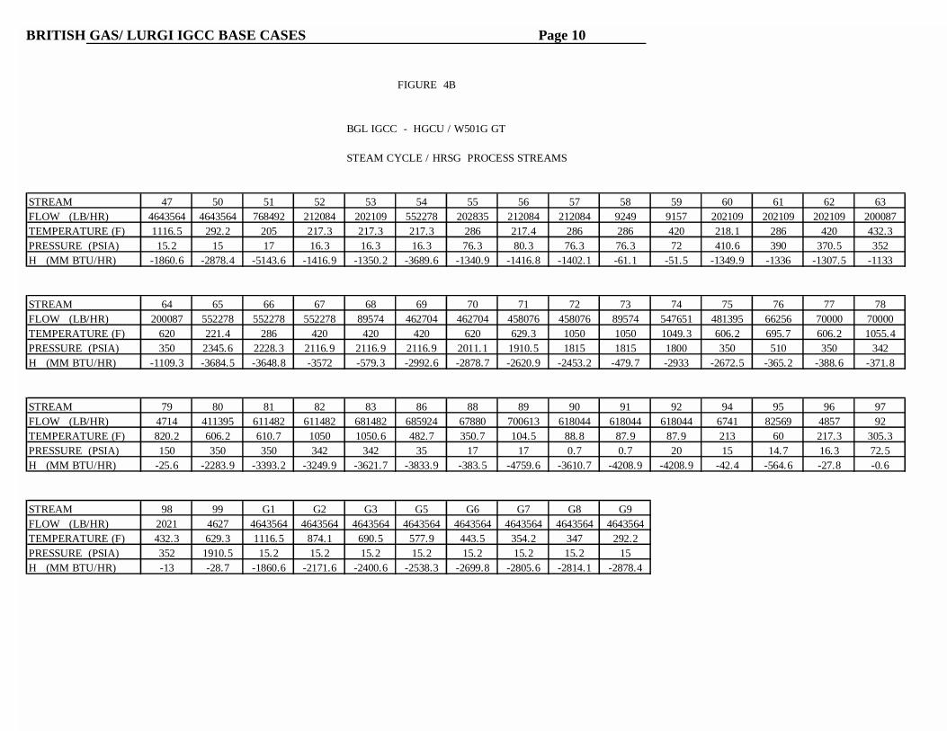
FIGURE 4B
BGL IGCC - HGCU / W501G GT
STEAM CYCLE / HRSG PROCESS STREAMS
STREAM 47 50 51 52 53 54 55 56 57 58 59 60 61 62 63FLOW (LB/HR) 4643564 4643564 768492 212084 202109 552278 202835 212084 212084 9249 9157 202109 202109 202109 200087TEMPERATURE (F) 1116.5 292.2 205 217.3 217.3 217.3 286 217.4 286 286 420 218.1 286 420 432.3PRESSURE (PSIA) 15.2 15 17 16.3 16.3 16.3 76.3 80.3 76.3 76.3 72 410.6 390 370.5 352H (MM BTU/HR) -1860.6 -2878.4 -5143.6 -1416.9 -1350.2 -3689.6 -1340.9 -1416.8 -1402.1 -61.1 -51.5 -1349.9 -1336 -1307.5 -1133
STREAM 64 65 66 67 68 69 70 71 72 73 74 75 76 77 78FLOW (LB/HR) 200087 552278 552278 552278 89574 462704 462704 458076 458076 89574 547651 481395 66256 70000 70000TEMPERATURE (F) 620 221.4 286 420 420 420 620 629.3 1050 1050 1049.3 606.2 695.7 606.2 1055.4PRESSURE (PSIA) 350 2345.6 2228.3 2116.9 2116.9 2116.9 2011.1 1910.5 1815 1815 1800 350 510 350 342H (MM BTU/HR) -1109.3 -3684.5 -3648.8 -3572 -579.3 -2992.6 -2878.7 -2620.9 -2453.2 -479.7 -2933 -2672.5 -365.2 -388.6 -371.8
STREAM 79 80 81 82 83 86 88 89 90 91 92 94 95 96 97FLOW (LB/HR) 4714 411395 611482 611482 681482 685924 67880 700613 618044 618044 618044 6741 82569 4857 92TEMPERATURE (F) 820.2 606.2 610.7 1050 1050.6 482.7 350.7 104.5 88.8 87.9 87.9 213 60 217.3 305.3PRESSURE (PSIA) 150 350 350 342 342 35 17 17 0.7 0.7 20 15 14.7 16.3 72.5H (MM BTU/HR) -25.6 -2283.9 -3393.2 -3249.9 -3621.7 -3833.9 -383.5 -4759.6 -3610.7 -4208.9 -4208.9 -42.4 -564.6 -27.8 -0.6
STREAM 98 99 G1 G2 G3 G5 G6 G7 G8 G9FLOW (LB/HR) 2021 4627 4643564 4643564 4643564 4643564 4643564 4643564 4643564 4643564TEMPERATURE (F) 432.3 629.3 1116.5 874.1 690.5 577.9 443.5 354.2 347 292.2PRESSURE (PSIA) 352 1910.5 15.2 15.2 15.2 15.2 15.2 15.2 15.2 15H (MM BTU/HR) -13 -28.7 -1860.6 -2171.6 -2400.6 -2538.3 -2699.8 -2805.6 -2814.1 -2878.4

BRITISH GAS/ LURGI IGCC BASE CASES Page 11
1. Process Descriptions
Two IGCC Base Cases have been developed based on the BGL gasification process. The BGLprocess uses an oxygen-blown, moving-bed, slagging gasifier. The Illinois #6 Coal is fed to thegasifier as a mixture of coarse coal (i.e. above 1/4"), fines, and coal briquettes. The oxygen issupplied from a cryogenic air separation plant (ASU) that is integrated with the gas turbinecompressor. The steam requirements are furnished from the bottoming steam cycle.
In Case 1, the raw fuel gas produced is cooled to remove the heavy hydrocarbon components(tars, oils, naphtha) which are recirculated to the gasifier. After additional cooling, the fuel gasthen enters a cold gas cleanup unit (CGCU) using the MDEA/Claus/Scot process for sulfurremoval and recovery. The cleaned fuel gas is reheated, resaturated and combined withrecirculated nitrogen from the ASU and sent to the gas turbine section.
In Case 2, the raw fuel gas is sent through a filter, to remove any particulates, and then through achloride guard bed before being sent to the transport desulfurization unit. The sulfur dioxidegenerated from the transport regenerator is sent to an acid plant for producing sulfur dioxide. The cleaned hot fuel gas is combined with recirculated nitrogen from the ASU and sent to the gasturbine section.
Power is recovered for both cases using a modified W501G gas turbine and a three-pressure levelreheat steam cycle. The composition for the as-received Illinois #6 Coal is listed below. Proximate : (Wt. %) (Wt. %, dry) Ultimate: (Wt. %) (Wt. % dry)Moisture 11.12 Moisture 11.12Ash 9.70 10.91 Carbon 63.75 71.72Volatiles 34.99 39.37 Hydrogen 4.50 5.06Fixed Carbon 44.19 49.72 Nitrogen 1.25 1.41 100 100 Chlorine 0.29 0.33
Sulfur 2.51 2.82HHV (Btu/lb) 11,666 13,126 Ash 9.70 10.91 Oxygen 6.88 7.75 100 100 The bitumen used as a binder in the briquetting process has the following composition:Ultimate Analysis: (Wt. %)Carbon 85.0 HHV (Btu/lb) 17,523Hydrogen 9.7Nitrogen 1.2Sulfur 3.4Oxygen 0.7
100

BRITISH GAS/ LURGI IGCC BASE CASES Page 12
Additional features for the case are given in following sections. In Table 2, overviews of theprocesses are given.
Table 2 : British Gas/ Lurgi IGCC Base Cases Process Overview
PROCESS SECTION CASE 1 CASE 2
Coal PrepBGL Gasifier Exit Temp / Press
Sizing, Briquetting
986 (F/ 395 psia
Sizing, Briquetting
973 (F/ 395 psia
Air Separation Plant Inlet Air Pres (psia) O2 Pres (psia) N2 Pres (psia)
27892
91 / 265
27892
91 / 265
Solid Waste Slag Quench Slag Quench
Gas Liquor Separation
Chloride/NH3 Removal
Low Temp Gas Cooling/Heat Recovery
Recovers, RecirculatesHeavy Hydrocarbons and
Removes Particulates.
Water Treatment
Removes Particulates &Chloride/NH3. Reheating
Fuel gas.
N/A
Chloride Guard Bed
N/A
Sulfur Removal CGCU-MDEA/CLAUS/SCOT
(elemental sulfur)
HGCU – TransportDesulfurization, Acid Plant
(sulfuric acid)
Clean Fuel Gas / Gas Addition N2 Recycle from ASU,water resaturating.
N2 Recycle from ASU
Gas Turbine - Power (MWe) - PR / TIT (F)
modified W501G272 (target)19.37 / 2583
Modified W501G272 (target)19.37 / 2583
Steam Cycle - Turb Press: HP/IP/LP - Superheat/Reheat - Exhaust LP Turb - HRSG Stack Temp
3 Pressure Level/Reheat 1800 / 342 / 35 (psia)
1050(F/ 1050(F0.67 psia292 (F
3 Pressure Level/Reheat 1800 / 342 / 35 (psia)
1050(F/ 1050(F0.67 psia292 (F

BRITISH GAS/ LURGI IGCC BASE CASES Page 13
1.1 Coal Prep / BGL Gasifier / Gas Liquor Separation
In the coal prep area, the as-received raw coal is first divided into fractions above and below 1/4"particle size. The coarse coal, along with a portion of the fines, is conveyed to the fuel storagearea. The excess fines are sent to the briquetting area, where they are first dried to removesurface moisture. The dryer is fired by the combustion of a small amount of clean fuel gas (bleedfrom the stream being sent to the gas turbine combustor). After the dryer, the fines are sent to abriquetting press that uses a bitumen binder. The coal briquettes produced are mixed with thecoarse coal, fines and flux (required to control slagging in the gasifier) in the fuel storage area.
The BGL gasifier is a counter-current, moving-bed, slagging gasifier operated at pressures of 360psia or higher. The reactor vessel is water cooled and refractory lined. The coal mixture (coarsecoal, fines, briquettes, and flux) is fed into the top of the gasifier via a lockhopper system andreacts while moving downward through the gasifier. The coal’s ash/mineral matter is removedfrom the bottom of the gasifier as molten slag through a slag tap, then quenched in water andremoved. Steam and oxygen are injected through tuyere nozzles near the base of the gasifier andreact with the coal as the gases move up. This counter-current action results in a widetemperature difference between the top and the bottom of the gasifier. The reactor can becharacterized due to this temperature profile as being divided into drying, devolatilization,gasification and combustion zones. Temperatures range from in excess of 3600(F in thecombustion zone to an exit product fuel gas temperature of approximately 900(F.
In Case 1, The hot dirty fuel gas leaving the gasifier enters a quench vessel and a BFW preheaterdesigned to lower the temperature to approximately 300(F. Entrained solids and solublecompounds are mixed with the exiting liquid and sent to the gas-liquor separation unit. Thesoluble hydrocarbon compounds, such as tars, oils, and naphtha are recovered from the aqueousliquor and recycled to the gasifier top and/or reinjected at the tuyeres.
Figures 1 and 3 illustrate the gasification section and major process streams relationship to otherprocess sections. In Table 3, gasifier conditions are listed for the BGL IGCC cases.

BRITISH GAS/ LURGI IGCC BASE CASES Page 14
Table 3. British Gas/ Lurgi IGCC Base Cases - Gasifier Conditions
CASE 1 CASE 2
Coal Flowrate (tons/day) - Total - to Dryer/Briquetting - Bitumen for Briquetting
Gasifier Flowrates (lb/hr) - Coal Feed (coarse,fines,briquettes) - Flux - Transport Nitrogen - Gasifier Steam - Oxidant - Raw Product Fuel Gas - Tars Recycle - Heavy Hydrocarbons Recycle
Gasifier Temperature Profile (((F) - Gasifier Exit - Devolatilization Zone Exit - Gasification Zone Exit - Combustion Zone Exit
285071351
237,52710,0769,661
75,006124,519446,2549,0198,841
986141317823548
257564446
214,5589,1748,821
66,256105,509378,604
N/AN/A
973132917623395
1.2 Air Separation Plant (ASU)
For both cases, an advanced high pressure cryogenic oxygen plant that takes advantage of the air(278 psia) extracted from the W501G gas turbine is employed. This advanced design is availabledue to recent improvements made to the conventional air separation technology which operatesefficiently only to about an air supply pressure of 170 psia. The advanced ASU by operating at ahigher pressure results in the oxygen and nitrogen products being available from the cold box athigher pressures than in a conventional ASU. This reduces costs for the further compression ofthese streams. For operational flexibility, (in startup and turndown), the present cases considerthat the air is supplied, in equal amounts (50%), from a bleed from the gas turbine compressorexhaust and as air supplied directly using a boost compressor. The GT Compressor bleed airpreheats a nitrogen recycle stream (98.9% purity) being sent to the gas turbine to assist in NOXcontrol and to increase the flowrate through the gas turbine expander. The nitrogen recycle isadjusted for each case to yield a net gas turbine power of approximately 272 MWe.. The amountof nitrogen recycle is about 35% for Case 1 and 66% for Case 2. The oxygen stream (95%purity) is supplied to the gasifier. Table 4 lists some of the key parameters for the ASU design.

BRITISH GAS/ LURGI IGCC BASE CASES Page 15
Table 4. British Gas/ Lurgi IGCC Base Cases - ASU Summary
Case 1 Case 2
% Air from Gas TurbineAir Inlet Press (psia)Total Air Flowrate (lb/hr)
Oxidant Stream - Flowrate (lb/hr) - Purity (mole % O2) - ASU Press (psia) - Boost Compr Press (psia)
Nitrogen Stream - Flowrate (lb/hr) - Purity (mole % N2) - ASU Pres (psia) - Boost Compr Press (psia) - % Recycled to GT - GT Recycle Temp ((F)
50278
522,639
124,51995.092
464
396,25698.9
91 / 26536035
204
50278
442,862
105,50995.092
464
335,76098.9
91 / 26530066
712
Power Requirements (MWe) - Air Compressor - O2 Boost Compressor - N2 Boost Compressors
11.42.92.8
9.72.54.3
1.3 Gas Cooling/COS Hydrolysis / Fuel Gas Saturation - Case 1
The raw fuel gas exits the BFW preheater (see Figure 1) in the gasification area and is sent to agas cooling section. This section cools the raw fuel gas in a series of heat exchangers to atemperature of 100 (F. A liquid waste stream is sent to the Gas Liquor separation process area.Any remaining hydrogen chloride and ammonia is removed in this liquid stream. The cooled rawfuel gas stream is reheated to 285 (F and enters a hydrolysis unit to convert COS to H2S. Thisstream is recooled to 100 (F and proceeds to the CGCU section for sulfur removal and recovery. This section�s heat recovery is used primarily to preheat water for use in resaturating the clean

BRITISH GAS/ LURGI IGCC BASE CASES Page 16
fuel gas returning from the CGCU section. Additionally, heat recovered in the CGCU section andfrom the air coolers preceding the ASU is used for reheating. The cleaned fuel gas from the CGCU section is combined with a nitrogen recycle stream andresaturated and reheated before being sent to the gas turbine section. This fuel stream is sent tothe gas turbine combustor at a temperature of 551 (F with a moisture content of 14.9 % (molarbasis). A small bleed of this clean fuel gas is sent to the Coal Prep section for use in coal drying.
1.4 Cold Gas Cleanup Unit (CGCU) - Case 1
The MDEA/Claus/SCOT process is used for cold gas cleanup and sulfur recovery. Refer toFigure 1 for a conceptual idea of the equipment setup for each process. In the MDEA step, thecooled fuel gas from the gas cooling section enters an absorber where it comes into contact withthe MDEA solvent. As it moves through the absorber, almost all of the H2S and a portion of theCO2 are removed. This clean fuel gas exits the absorber and is sent back to the gas cooling andfuel saturation area described in the preceding report section. The solute-rich MDEA solventexits the absorber and is heated by the solute-lean solvent from the stripper in a heat exchangerbefore entering the stripping unit. Acid gases from the top of the stripper are sent to theClaus/SCOT unit for sulfur recovery. The lean MDEA solvent exits the bottom of the stripper andis cooled through several heat exchangers. It is then cleaned in a filtering unit and sent to astorage tank before the next cycle begins.
The Claus process is carried out in two stages. In the first stage, about one-quarter of the gasesfrom the MDEA unit, which exit at 145(F, are mixed with the recycle acid gases from the SCOTunit and are burned in the first furnace. The remaining acid gases are added to the second-stagefurnace, where the H2S and SO2 react in the presence of a catalyst to form elemental sulfur. Thegas is cooled in a waste heat boiler and then sent through a series of reactors where more sulfur isformed. The sulfur is condensed and removed between each reactor. A tail gas stream containingunreacted sulfur, SO2, H2S, and COS is sent for further processing in the SCOT unit. This tailgas is heated before entering a reactor where SO2 converts to H2S with the aid of a cobalt-molybdate catalyst. The effluent is cooled by waste heat boilers and direct quench before beingsent to an absorber column where the H2S is removed. The H2S rich stream is sent to theregenerator before being recycled to the absorber. The acid gas from the regenerator is recycledto the Claus step. Further information is provided in Table 5.

BRITISH GAS/ LURGI IGCC BASE CASES Page 17
Table 5. British Gas/ Lurgi IGCC Base Cases - CGCU Conditions
Case 1
Sulfur Balance: (lb sulfur/hr) - MDEA Feed - Acidgas to Claus - Cleaned Fuel Gas - Sulfur Product - SCOT Vent Gas
Key Conditions - PPMV to CGCU - PPMV Clean Fuel Gas - Sulfur Recovery (weight %) - Steam Requirements (lb/hr) - Power Requirements (KWe)
5924.25897.726.0
5889.09.1
977444.699.6
74421765
1.5 Chloride Guard Bed / Fine Particulate Removal - Case 2
For Case 2, the raw fuel gas exits the particulate removal filter (at 904(F ) and is sent to chlorideguard bed section for hydrogen chloride removal. These guard beds containing commercial gradeNahcolite capture the chloride and any other halogens. The beds will require periodic treatmentand operate with several on-line while others are being renewed. The resulting fuel gas stream issent to the HGCU section for sulfur removal. A gas filter is used following the HGCU section toguard against any fine particulates left (or generated in HGCU) in the clean fuel gas sent to thegas turbine.
1.6 Transport Desulfurization HGCU - Case 2
The representation for this section was based on information provided by L. Bissett (NETL). NETL is currently developing an on-site (Morgantown) pilot plant to test this HGCU option for anumber of sorbents. In the HGCU section, the transport absorber operates at an inlet pressure of 380 psia. A zinc based sorbent is used. The reaction occurs as a simple exchange between theZnO portion of the sorbent and the sulfur. The cleaned fuel gas exits at 1003(F and enters a gasfilter to capture any particulates before being sent to the gas turbine combustor. (A small portionof the cleaned filtered fuel gas is recycled and pressurized for use in the gas filter.)
The absorber consists of a riser reaction section, a solids/gas separation vessel, and a solids returndipleg. The riser operates at a high void fraction of approximately 95 percent. The large amount

BRITISH GAS/ LURGI IGCC BASE CASES Page 18
of sorbent recirculation results in only a small change in the sorbent sulfur content through thissection. A slip stream of approximately 10 percent of the sorbent stream exiting the separationvessel is sent to a regenerator riser, while the remaining portion is combined with regeneratedsorbent and sent back for the next absorber cycle. The regenerator is assumed to remove only aportion of the absorbed sulfur. This removal matches the sulfur that is removed from the raw fuelgas that enters the absorber. Since only a small amount of sulfur reacts, the regenerator exittemperature can be controlled to a value of approximately 1400 (F by adjusting the amounts ofair (from GT) and nitrogen (from ASU) used. The regenerator waste gas stream is recycled tothe sulfuric acid plant for SO2 removal. HGCU conditions are listed in Table 6.
1.7 Sulfuric Acid Plant - Case 2
In the simulation model, no process details were used to represent the sulfuric acid plant. Theonly item taken into consideration was the acid plant power consumption rate of 46 watts perlb/hr SO2 fed to the plant. The sulfuric acid production was based on closing the sulfur balance. However, the following process was used as a basis for the cost analysis.
The regeneration gas from the desulfurization section enters the sulfuric acid plant and passesover a vanadium catalyst stage at temperatures between 800 and 825(F. The temperature isallowed to increase adiabatically as the SO2 is converted to SO3. After the reaction is 60 to 70percent complete, it is stopped. The gas stream is then cooled in a waste heat boiler and passedthrough subsequent stages of catalyst until the temperature of the gas passing through the laststage is below 800 (F. This process usually requires two to three stages of catalyst. Once cooled,the gas stream is sent to an intermediate absorber tower where some of the SO3 is removed with98 percent sulfuric acid. The gases leaving the absorber are reheated and passed over theremaining catalyst stages in a converter. The gases are again cooled and sent to a final absorbertower. Upon exiting the final absorber, the gases are vented to the atmosphere. The conversionof SO2 to SO3, and subsequently Sulfuric Acid, using this process is about 99.8 percent.

BRITISH GAS/ LURGI IGCC BASE CASES Page 19
Table 6. British Gas/ Lurgi Gasifier IGCC Base Cases- HGCU Conditions______________________________________________________________________________Sulfur Balance Information:
Flowrate (lb/hr) Sulfur in Raw Fuel Gas 5447.6Sulfur in Regenerator Waste 5447.2Sulfur in Clean Fuel Gas 6.0(ASPEN Convergence Error Sulfur %) 0.103
PPMV of Sulfur in Raw Fuel Gas 9330PPMV of Sulfur in Clean Fuel Gas 10 (Set in simulation)HGCU Sulfur Capture Eff. (weight %) 99.89Mole % SO2 in Regenerator Waste 9.8Regenerator Exit Gas Temp ((F) 1442Regenerator Air Temp ((F) 167
HGCU Solids: Flowrate (1000 lb/hr) Sorbent Utilization *To Absorber Rise 4157.82 0.443From Absorber Separator 4160.55 0.450To Regenerator Riser 416.05 0.450From Regenerator Separator 413.33 0.381Ratio: Solids to Absorber/Solids to Regenerator = 9.99
* Sorbent utilization = moles of ZnS/total moles of ZnX compounds
1.8 Gas Turbine
The cases were based on using a modified W501G gas turbine that was integrated with the AirSeparation Unit (ASU). From the compressor exhaust, a bleed stream is used to supplyapproximately half of the air supply needed for the ASU. An additional bleed, 14% of thecompressor discharge air, is chilled to 600(F and used for cooling in the turbine expander. Heatrecovered from the air cooler is used in the steam cycle. For Case 2, the compressor dischargealso supplies air for use in the HGCU regenerator. The remainder of the compressor discharge airis sent directly to the combustor. The fuel gas stream is augmented by the addition of a nitrogenstream supplied from the ASU. This approach is employed to both assist in NOX control and toincrease the flowrate which increases the power generated in the turbine expander. The nitrogenrecycle flowrate is set by requiring that the gas turbine power generated equals approximately 272MWe. Combustor duct cooling is accomplished using intermediate pressure steam supplied fromthe steam bottoming cycle. This reheated steam is returned to the steam cycle. The combustor

BRITISH GAS/ LURGI IGCC BASE CASES Page 20
exhaust gases enter the expander (2581(F, 269 psia), where energy is recovered to producepower.
The original turbine design specifications are based on a natural gas fuel rather than a coal derivedsyngas. The syngas�s significantly lower heating value when compared to natural gas requires ahigher flow rate to obtain the desired turbine firing temperature. To allow for the higher flowrate, an increase in the first nozzle areas will be required. The original combustor will also bereplaced with a modified design to handle the lower BTU syngas. In Table 7, the fuel gascomposition for both cases is listed both with and without the nitrogen addition. In Table 8, thegas turbine conditions are listed.
Table 7. British Gas/ Lurgi IGCC Base Cases - Fuel Gas Composition (Mole %)
(No Nitrogen Recycle) (With Nitrogen Recycle)Mole % Case 1 Case 2 Case 1** Case 2
CGCU HGCU CGCU HGCU O2 - --- 0.1 0.2 N2 2.3 2.1 19.4 31.3 Ar 0.6 0.5 0.5 0.5 H2 29.9 26.7 20.1 18.6 CO 53.8 46.3 36.2 32.3 CO2 5.2 5.9 3.4 4.1 H2O 0.3 10.2 14.9 7.2 CH4 7.5 6.9 5 4.8 H2S 45 PPMV 10 PPMV 26 PPMV 7 PPMV COS 0.4 PPMV 2 PPBV 0.3 PPMV 1.4 PPBV C2+ 0.5 -- 0.3 --- C6+ - 0.4 --- 0.3 NH3 - 1.1 --- 0.7
Heating 353 336 238 235Value (HHV)(Btu/Scf)(** Note: For Case 1 the nitrogen is added to the fuelgas, which is thenmoisturized with water)

BRITISH GAS/ LURGI IGCC BASE CASES Page 21
Table 8. British Gas/ Lurgi IGCC Base Cases - W501G Gas Turbine Conditions
CASE 1 CASE 2
Pressure (psia) - to Filter - Compressor inlet - Compressor outlet - Combustor exit - Expander exhaust Pressure Ratio
Flowrates (lb/hr) - Compressor Inlet Air - Combustor Inlet Air - Bleed Air to ASU - Bleed Air to HGCU - Air Cooling Bleed - Air Compr Leakage - Steam Combustor Duct Cooling - Fuel Gas - Expander Exhaust Gas to HRSG
14.714.5728226915.219.4
4,320,000
3,517,530 261,884
N/A527,10913,47870,000
573,2554,617,890
*(Same as Case 1)*****
*3,522,060221,90235,454
* **
596,4404,643,560
Temperature ((F) - Inlet Air - Compressor outlet - Fuel Gas - Combustor exhaust - Turbine inlet - Turbine exhaust
59813551261325831124
**
919**
1116
Power (MWe) - Compressor - Expander - Generator Loss - Net Gas Turbine
-237.2513.6-3.9
272.6
-237.2513.6-3.9
272.5

BRITISH GAS/ LURGI IGCC BASE CASES Page 22
1.9 Steam Cycle
The steam cycle used for the two cases is based on a design by D. Turek (ABB Power PlantLaboratories). Pressure drops and steam turbine isentropic efficiencies were based on informationfrom a study by Bolland1. The cycle is a three-pressure level reheat process. Major componentsinclude a heat recovery steam generator (HRSG), steam turbines (high, intermediate, and lowpressure), condenser, steam bleed for gas turbine cooling, recycle water heater, and deaerator.
In Figure 2 and Figure 4, the steam cycle and process flows are provided for the two cases. Theprimary heat recovered is from the exhaust gas stream of the gas turbine and from the BGLgasifier section. Additionally, heat is integrated for steam generation from any recoverablegasifier island heat source not required for use in reheating process streams. For example, in Case2, the heat available from the air compressor bleed air chiller is used in steam generation. However, in Case 1, this heat source is used in reheating the fuel gas and is not available to thesteam cycle. Case 1, due to the use of CGCU, has available several sources of medium to lowquality heat that are used to both reheat condensate and to generate low pressure steam (seestreams 87 - 89, in Figure 2A). Case 2 uses a HGCU for the fuel gas and has available lowquality heat to reheat the condensate to only 120(F. Further reheating of the condensate streamto 205(F requires a steam bleed (see stream 88, Figure 4A).
Steam generation occurs at the three pressure levels of 72.5 psia, 353 psia, and 1911 psia in theHRSG. The cycle includes a parallel superheating/reheating section that raises the temperature to1050(F for both the high-pressure steam and for the combined intermediate pressure steam andhigh-pressure turbine exhaust steam. Steam is extracted for the gasifier (510 psia) and gas turbineduct cooling (350 psia) from the HP steam turbine. The return steam from the gas turbine ductcooling is combined with reheat steam and sent to the IP steam turbine. An additional steamextraction (150 psia) from the IP turbine is used to provide steam requirements for the CGCU(Case 1 only) and Coal Prep areas. The LP steam turbine discharges at 89(F and 0.67 psia. Thesteam cycle conditions are summarized in Table 9.
� "A Comparative Evaluation of Advanced Combined Cycle Alternatives", Transactions of the ASME, April 1991.

BRITISH GAS/ LURGI IGCC BASE CASES Page 23
Table 9. British Gas/ Lurgi IGCC Base Cases - Steam Cycle Conditions______________________________________________________________________________HRSG Stack Gas Temperature: 292 (FDeaerator Vent: 0.5% of inlet flowrateLP,IP, and HP drum blowdown: 1.0% of inlet flowratePressure drops: 5% of inlet (except IP superheater - 2 psia and line Drop before HP turbine - 15 psia)High Pressure Turbine Inlet: 1800 psia / 1050 (FIntermediate Pressure Turbine Inlet: 342 psia / 1050 (FLow Pressure Turbine Inlet: 35 psiaLow Pressure Turbine Exhaust: 0.67 psia
PressureLevel
Steam Conditions Pressure Saturation Temp (psia) (((F)
HRSG Approach Delta Temp (((F) CASE 1 CASE 2
LowIntermediate High
72.5 305 352 432 1911 629
50 42 15 11 61 61
Power Production (MWe) CASE 1 CASE 2
Steam Turbines Generator Loss Net Steam Turbines Pumps
135.4-2.0
131.4-1.6
132.3-2.0
130.3-1.6
_____________________________________________________________________________
1.10 Power Production
An auxiliary power consumption is assumed as 3 percent of the total power production by the GasTurbine and the Steam Turbines minus the power consumed by the miscellaneous pumps,expanders, compressors, and blowers. The power production and the overall process efficiencyare listed in Table 10 for the BGL IGCC case.

BRITISH GAS/ LURGI IGCC BASE CASES Page 24
Table 10. British Gas/ Lurgi IGCC Base Cases - Power Production
CASE 1 CASE 2CGCU HGCU
Gas Turbine (MWe) 272.6 272.5Steam Turbine (MWe) 133.4 130.3Miscellaneous (MWe) -19.5 -19.2Auxiliary (MWe) -11.6 -11.5Plant Total (MWe) 374.9 372.1Overall Process Efficiency (HHV, %) 45.3 49.4Overall Process Efficiency (LHV, %) 47.1 51.3
2. Simulation Development
The BGL IGCC gasifier island section was developed based on information available in severalEPRI reports by BGL. The ASPEN PLUS model for the gasifier was adapted from an earlierDOE sponsored study by Gilbert/Commonwealth. Specifically, the references included:
& DOE Report: (used for ASPEN PLUS gasifier model)- ASPEN Model and Economics of a BGC/Lurgi Slagging Gasifier with Hot
Gas Desulfurization in a combined-cycle mode, January 1991.& EPRI Reports:
- U.S. Bituminous Coal Test Program in the British Gas/Lurgi (BGL) Gasifier, EPRI GS-7091, December 1991.- Evaluation of 450-MWe BGL GCC Power Plants Fueled with a Pittsburgh
No. 8 Coal, EPRI TR-100376, November 1992.
The models for the gas turbine (W501G ), gas cleanup, ASU and the steam cycle were based onpreviously developed ASPEN Plus Base Case Simulations (FY98 cases). Some sections of theASPEN PLUS code were based on earlier BGL IGCC ASPEN simulations developed for theDOE. These earlier cases are stored in the ASPEN Archive CMS Library (i.e. CMS BC3-1C andCMS BC3-20C). The ASPEN PLUS (version 10.1) simulation codes are stored in the EG&G�sProcess Engineering Team Library.

BRITISH GAS/ LURGI IGCC BASE CASES Page 25
3. Cost of Electricity Analysis
The cost of electricity for the BGL cases were performed using data from the EG&G CostEstimating notebook and several contractor reports. The format follows the guidelines set byEPRI TAG. Details of the individual section costs are described below and are based on capacity-factored techniques. The COE spreadsheets are included in Appendix A. All costs are reportedin 1st Quarter 1999 dollars.
3.1 Coal Handling/ Conveying/ Briquetting
The coal preparation section includes costs for coal hoppers, feeders, conveyors, screeningfacilities, and briquetting facilities. The coal flow rate in Case 1 is 2850 tons per day (Illinois #6coal), resulting in a combined section cost of $29.3 million. The coal flow rate in Case 2 is 2575tons per day (Illinois #6 coal), resulting in a combined section cost of $27.2 million.
3.2 Flux Receiving/Handling
The flux preparation section includes storage and conveying of the flux. The flux flow rate forCase 1 is 121 tons per day, resulting in a section cost of $3.2 million. The flux flow rate for Case2 is 110 tons per day, resulting in a section cost of $3.0 million.
3.3 Oxygen Plant
The cost for the oxygen plant includes the air separation unit, the air precoolers, the oxygencompressors, the nitrogen compressors and the air compressors. Both systems use a high-pressure air separation unit. The oxygen plant for Case 1 produces 1471 tons per day oxygenwith a cost of $32.0 million. The oxygen plant for Case 2 produces 1266 tons per day oxygenwith a cost of $29.2 million.
3.4 British Gas/ Lurgi Gasifier
The cost for the gasification section includes the gasifier, the quench unit, the BFW preheater andthe slag handling equipment. Both cases are based on two gasification trains. Case 1, with anominal capacity of 1400 tons per day per train, has a cost of $61.8 million. Case 2, with anominal capacity of 1300 tons per day per train, has a cost of $57.6 million. A processcontingency of 15 percent was added to the total plant cost based on the development of thegasifier.

BRITISH GAS/ LURGI IGCC BASE CASES Page 26
3.5 Low Temperature Gas Cooling/Fuel Gas Saturation and Gas LiquorSeparation and Treatment - CASE 1 only
The cost for the low temperature cooling and gas saturation section includes several heatexchangers, separators, and the saturator column. The cost is $9.8 million.
The gas liquor separation and treatment sections include the tar and oil separators, expansionvessels, product storage tank, strip columns, incinerator, and precipitator. The total cost of thesections is $11.6 million.
3.6 MDEA/ Claus/ SCOT Section - CASE 1 only
The cost of the MDEA acid gas removal system includes the absorber column, the strippingcolumn, heat exchanger and pumps. The cost is $4.7 million.
The cost for the Claus/SCOT sulfur recovery and tail gas treating units is based on 71 tons perday of sulfur entering the unit. The total cost for both units is $13.2 million.
3.7 Gas Conditioning - CASE 2 only
The gas conditioning section includes the gas filters and chloride guard beds. The cost for Case 2is $11.4 million and is based on two process trains. A process contingency of 15% was added tothe total plant cost based on the development of the gas conditioning components.
3.8 Desulfurization Section - CASE 2 only
The cost for the transport desulfurization section was derived from a previous report2. Thisincludes costs for sorbent hoppers, transport desulfurizer and cyclones. However, the previousreport was for a polishing unit and it is unclear how no sulfur capture in the gasifier will affect theprice of the unit or the amount of sorbent needed. The amount of sorbent used was basedinformation from the Separations and Gasification Engineering Division of NETL. The cost forthe transport desulfurization section is $9.5 million and is based on two process trains. A processcontingency of 15% was added to the total plant cost based on the development of thedesulfurization sections.
��Advanced Technology Repowering,� Final Report, Prepared for the U.S. Department of Energy, Morgantown
Energy Technology Center, Prepared by Parsons Power Group, Inc. May 1997

BRITISH GAS/ LURGI IGCC BASE CASES Page 27
3.9 Acid Plant Section - CASE 2 only
The cost for the sulfuric acid plant is based on a Monsanto contact process. The unit produces200 tons per day of sulfuric acid and costs $16.8 million.
3.10 Gas Turbine Section
The cost for the W501G gas turbine was derived from the Gas Turbine World 96 Handbook3. The cost from the handbook was $185/kW and included all the basic turbine components. Afactor of 7% was added for modifications and installation. The gas turbine powers of Case 1,272.6 MWe and Case 2, 272.5 resulted in an approximate cost of $54 million. A processcontingency of 5% was added to the total plant cost based on the development of the modifiedgas turbines.
3.11 HRSG/ Steam Turbine Section
The cost for the steam cycle is based on a three-pressure level steam cycle. The steam turbinepower for Case 1 is 133.4 MWe, with a combined section cost of $43 million. The steam turbinepower for Case 2 is 130.3 MWe, with a combined section cost of $42.5 million.
3.12 Bulk Plant Items
Bulk plant items include water systems, civil/structural/architectural, piping, control andinstrumentation, and electrical systems. These were calculated based on a percentage of the totalinstalled equipment costs. The percentages in parenthesis are for the hot-gas cleanup process,which has a lower water requirement, and therefore, a smaller percentage for piping and watersystems. The following percentages were used in this report.
Bulk Plant Item % of Installed Equipment CostWater Systems 7.1 (5.1)Civil/Structural/Architectural 9.2Piping 7.1 (5.1)Control and Instrumentation 2.6Electrical Systems 8.0
Total 34.0 (30.0)
Table 11, Table 12, and Table 13 show the assumptions used in this COE analysis. The totalcapital requirement for the BGL CGCU Case 1 is $533,664,000 or $1423/kW. The total capital
� Gas Turbine World Performance Specifications, annual issue, Pequot Publishing Inc., Fairfield Connecticut.

BRITISH GAS/ LURGI IGCC BASE CASES Page 28
requirement for the BGL HGCU Case 2 is $503,640,000 or $1354/kW. The levelized cost ofelectricity for the case in constant dollars for Case 1 is 44.5 mills/kWh and for Case 2 is 41.1mills/kWh.
* PPC = Process Plant Cost** TPC = Total Plant Cost*** TPI = Total Plant Investment
Table 11. Capital Cost Assumptions
Engineering Fee 10% of PPC*Project Contingency 15% of PPCConstruction Period 4 YrsInflation Rate 3%Discount Rate 11.2%Prepaid Royalties 0.5% of PPCCatalyst and Chemical Inventory 30 DysSpare Parts 0.5% of TPC**Land 200 Acres @ $6,500/Acre
Start-Up CostsPlant Modifications 2% of TPI***Operating Costs 30 DysFuel Costs 7.5 Dys
Working CapitalCoal 60 DysBy-Product Inventory 30 DysO&M Costs 30 Dys

BRITISH GAS/ LURGI IGCC BASE CASES Page 29
Table 12. Operating & Maintenance AssumptionsConsumable Material PricesIllinois #6 Coal $29.40/TonRaw Water $0.19 /TonMDEA Solvent $1.45/LbClaus Catalyst $470/TonSCOT Activated Alumina $0.067/LbSorbent $6,000/TonNahcolite $275/Ton
Off-Site Ash/Sorbent Disposal Costs $8.00/TonOperating Royalties 1% of Fuel CostOperator Labor $34.00/hourNumber of Shifts for Continuous Operation 4.2Supervision and Clerical Labor 30% of O&M LaborMaintenance Costs 2.2% of TPCInsurance and Local Taxes 2% of TPCMiscellaneous Operating Costs 10% of O&M LaborCapacity Factor 85%
Table 13. Investment Factor Economic AssumptionsAnnual Inflation Rate 3%Real Escalation Rate (over inflation)
O&M 0%Coal -1.1%
Discount Rate 11.2%
Debt 80% of Total 9.0% Cost 7.2% ReturnPreferred Stock 0% of Total 0.0% Cost 0% ReturnCommon Stock 20% of Total 20.0% Cost 4.0% Return
11.2% Total
Book Life 20 YrsTax Life 20 YrsState and Federal Tax Rate 38%Investment Tax Credit 0%Number of Years Levelized Cost 10 Yrs

BRITISH GAS/ LURGI IGCC BASE CASES Page 30
Appendix A

BRITISH GAS/ LURGI IGCC BASE CASES Page 31
British Gas/ Lurgi CGCU IGCC CASE 1 375 MW POWER PLANT1st Q 1999 Dollar
Total Plant Investment PROCESS PROCESS COST, K$AREA NO PLANT SECTION DESCRIPTION CONT, % CONT, K$ W/O CONT11 Coal Receiving/ Handling 0 $0 $14,08811 Flux Receiving/Handling 0 $0 $3,23111 Coal Screening/Conveying/Briquetting 0 $0 $15,16212 Oxygen Plant 0 $0 $32,04212 BGL Gasifier (2) 15 $9,271 $61,80414 Gas Liquor Separation 0 $0 $5,28414 Gas Liquor Treatment 0 $0 $6,35514 Low Temperature Gas Cooling/Gas Saturation 0 $0 $9,82114 MDEA 0 $0 $4,66514 Claus 0 $0 $9,27514 SCOT 0 $0 $3,92215 Gas Turbine System 5 $2,705 $54,09615 HRSG/Steam Turbine 0 $0 $42,95018 Water Systems 0 $0 $18,65130 Civil/Structural/Architectural 0 $0 $24,16840 Piping 0 $0 $18,65150 Control/ Instrumentation 0 $0 $6,83060 Electrical 0 $0 $21,016
Subtotal, Process Plant Cost $352,012
Engineering Fees $35,201Process Contingency (Using cont. listed) $11,975Project Contingency, 15 % Proc Plt & Gen Plt Fac $52,802
Total Plant Cost (TPC) $451,991
Plant Construction Period, 4.0 Years (1 or more)Construction Interest Rate, 11.2 %Adjustment for Interest and Inflation $56,738
Total Plant Investment (TPI) $508,729
Prepaid Royalties $1,760Initial Catalyst and Chemical Inventory $284Startup Costs $12,672Spare Parts $2,260Working Capital $6,659Land, 200 Acres $1,300
Total Capital Requirement (TCR) $533,664$/kW 1423

BRITISH GAS/ LURGI IGCC BASE CASES Page 32
ANNUAL OPERATING COSTS – CASE 1
Capacity Factor = 85 %UNIT $ ANNUAL
COST ITEM QUANTITY PRICE COST, K$Coal (Illinois #6) 2,850 T/D $29.40 /T $25,997
Consumable MaterialsWater 2,942 T/D $0.19 /T $173Limestone 121 T/D $16.00 /T $600Bitumen 50 T/D $130.00/T $2,014MDEA Solvent 403.2 Lb/D $1.45 /Lb $181Claus Catalyst 0.01 T/D $470 /T $1SCOT Activated Alumina 15.9 Lb/D $0.67 /Lb $3SCOT Cobalt Catalyst $5SCOT Chemicals $16
Ash/Sorbent Disposal Costs 413 T/D $8.00 /T $1,026
Plant Labor Oper Labor (incl benef) 15 Men/shift $34.00 /Hr. $4,455 Supervision & Clerical $2,530
Maintenance Costs 2.2% $9,944
Royalties $260
Other Operating Costs $843
Total Operating Costs $48,050
By-Product CreditsSulfur 69.0 T/D $75.00 /T $1,605__________________ 0.0 T/D $0.00 /T $0__________________ 0.0 T/D $0.00 /T $0__________________ 0.0 T/D $0.00 /T $0
Total By-Product Credits $1,605
Net Operating Costs $46,445

BRITISH GAS/ LURGI IGCC BASE CASES Page 33
BASES AND ASSUMPTIONS – CASE 1A. CAPITAL BASES AND DETAILS
UNIT $QUANTITY PRICE COST, K$
Initial Cat./Chem. Inventory Water 75024 T $0.19 /T $14Limestone 3083 T/D $16.00 /T $49Bitumen 1273 T/D $130.00/T $166MDEA Solvent 10282 Lb $1.45 /Lb $15Claus Catalyst 0.3 T $470 /T $0SCOT Activated Alumina 405 Lb $0.67 /Lb $0SCOT Cobalt Catalyst $16SCOT Chemicals $24
Total Catalyst and Chemical Inventory $284
Startup costs Plant modifications, 2 % TPI $10,175 Operating costs $1,869 Fuel $628
Total Startup Costs $12,672
Working capital Fuel & Consumables inv 60 days supply $5,603 By-Product inventory 30 days supply $155 Direct expenses 30 days $901
Total Working Capital $6,659
B. ECONOMIC ASSUMPTIONSProject life 20 YearsBook life 20 YearsTax life 20 YearsFederal and state income tax rate 38.0 %Tax depreciation method MACRSInvestment Tax Credit 0.0 %Financial structure
% of Current Dollar Constant Dollar Type of Security Total Cost, % Ret, % Cost, % Ret, % Debt 80 9.0 7.2 5.8 4.6 Preferred Stock 0 3.0 0.0 0.0 0.0 Common Stock 20 20.0 4.0 16.5 3.3 Discount rate (cost of capital) 11.2 7.9
Inflation rate, % per year 3.0Real Escalation rates (over inflation) Fuel, % per year -1.1 Operating & Maintenance, % per year 0.0

BRITISH GAS/ LURGI IGCC BASE CASES Page 34
C. COST OF ELECTRICITY – CASE 1
The approach to determining the cost of electricity is based upon the methodology describedin the Technical Assessment Guide, published by the Electric Power Research Institute. The cost of electricity is stated in terms of 10th year levelized dollars.
Current $ Constant $Levelizing Factors Capital Carrying Charge, 10th yr 0.179 0.148 Fuel, 10th year 1.091 0.948 Operating & Maintenance, 10th yr 1.151 1.000
Cost of Electricity - Levelized mills/kWh mills/kWh Capital Charges 34.2 28.4 Fuel Costs 10.2 8.8 Consumables 1.7 1.4 Fixed Operating & Maintenance 6.3 5.5 Variable Operating & Maintenance 1.1 1.0 By-product -0.7 -0.6
Total Cost of Electricity 52.8 44.5

BRITISH GAS/ LURGI IGCC BASE CASES Page 35
British Gas/ Lurgi HGCU IGCC CASE 2 372 MW POWER PLANT1st Q 1999 Dollar
Total Plant Investment PROCESS PROCESS COST, K$AREA NO PLANT SECTION DESCRIPTION CONT, % CONT, K$ W/O CONT11 Coal Receiving/ Handling 0 $0 $13,12211 Flux Receiving/Handling 0 $0 $3,02611 Coal Screening/Conveying/Briquetting 0 $0 $14,12212 Oxygen Plant 0 $0 $29,24112 BGL Gasifier (2) 15 $8,636 $57,57412 Gas Compression (Recycle) 5 $91 $1,81514 Gas Conditioning (2) 15 $1,707 $11,38014 Air Boost Compressor 0 $0 $66614 Transport Desulfurizer (2) 15 $1,422 $9,48014 Sulfuric Acid Plant 0 $0 $16,75915 Gas Turbine System 5 $2,704 $54,07615 HRSG/Steam Turbine 0 $0 $42,52018 Water Systems 0 $0 $12,94330 Civil/Structural/Architectural 0 $0 $23,34840 Piping 0 $0 $12,94350 Control/ Instrumentation 0 $0 $6,59860 Electrical 0 $0 $20,302
Subtotal, Process Plant Cost $329,915
Engineering Fees $32,991Process Contingency (Using cont. listed) $14,560Project Contingency, 15 % Proc Plt & Gen Plt Fac $49,487
Total Plant Cost (TPC) $426,953
Plant Construction Period, 4.0 Years (1 or more)Construction Interest Rate, 11.2 %Adjustment for Interest and Inflation $53,595
Total Plant Investment (TPI) $480,548
Prepaid Royalties $1,650Initial Catalyst and Chemical Inventory $361Startup Costs $11,738Spare Parts $2,135Working Capital $5,908Land, 200 Acres $1,300
Total Capital Requirement (TCR) $503,640$/kW 1354

BRITISH GAS/ LURGI IGCC BASE CASES Page 36
ANNUAL OPERATING COSTS – CASE 2
Capacity Factor = 85 %UNIT $ ANNUAL
COST ITEM QUANTITY PRICE COST, K$Coal (Illinois #6) 2,575 T/D $29.40 /T $23,487
Consumable MaterialsWater 1,100 T/D $0.19 /T $65HGCU Sorbent 0.05 T/D $6,000 /T $97Nahcolite 3.0 T/D $275 /T $256Limestone 110.0 T/D $16 /T $546Bitumen 46.2 T/D $130 /T $1,861
Ash/Sorbent Disposal Costs 382 T/D $8.00 /T $949
Plant Labor Oper Labor (incl benef) 15 Men/shift $34.00 /Hr. $4,455 Supervision & Clerical $2,464
Maintenance Costs 2.2% $9,393
Royalties $235
Other Operating Costs $821
Total Operating Costs $44,630
By-Product CreditsSulfuric Acid 199.7 T/D $68.00 /T $4,214__________________ 0.0 T/D $0.00 /T $0__________________ 0.0 T/D $0.00 /T $0__________________ 0.0 T/D $0.00 /T $0
Total By-Product Credits $4,214
Net Operating Costs $40,416

BRITISH GAS/ LURGI IGCC BASE CASES Page 37
BASES AND ASSUMPTIONS – CASE 2A. CAPITAL BASES AND DETAILS
UNIT $QUANTITY PRICE COST, K$
Initial Cat./Chem. Inventory Water 28050 T $0.19 /T $5HGCU Sorbent 23 T/D $6,000 /T $136Nahcolite 77 T/D $275 /T $21Limestone 2805 T/D $16 /T $45Bitumen 1177 T/D $130 /T $153
Total Catalyst and Chemical Inventory $361
Startup costs Plant modifications, 2 % TPI $9,611 Operating costs $1,560 Fuel $568
Total Startup Costs $11,738
Working capital Fuel & Consumables inv 60 days supply $4,623 By-Product inventory 30 days supply $407 Direct expenses 30 days $878
Total Working Capital $5,908
B. ECONOMIC ASSUMPTIONS
Project life 20 YearsBook life 20 YearsTax life 20 YearsFederal and state income tax rate 38.0 %Tax depreciation method MACRSInvestment Tax Credit 0.0 %Financial structure
% of Current Dollar Constant Dollar Type of Security Total Cost, % Ret, % Cost, % Ret, % Debt 80 9.0 7.2 5.8 4.6 Preferred Stock 0 3.0 0.0 0.0 0.0 Common Stock 20 20.0 4.0 16.5 3.3 Discount rate (cost of capital) 11.2 7.9
Inflation rate, % per year 3.0Real Escalation rates (over inflation) Fuel, % per year -1.1 Operating & Maintenance, % per year 0.0

BRITISH GAS/ LURGI IGCC BASE CASES Page 38
C. COST OF ELECTRICITY - CASE 2
The approach to determining the cost of electricity is based upon the methodology describedin the Technical Assessment Guide, published by the Electric Power Research Institute. The cost of electricity is stated in terms of 10th year levelized dollars.
Current $ Constant $Levelizing Factors Capital Carrying Charge, 10th yr 0.179 0.148 Fuel, 10th year 1.091 0.948 Operating & Maintenance, 10th yr 1.151 1.000
Cost of Electricity - Levelized mills/kWh mills/kWh Capital Charges 32.5 27.0 Fuel Costs 9.2 8.0 Consumables 1.6 1.4 Fixed Operating & Maintenance 6.1 5.3 Variable Operating & Maintenance 1.1 0.9 By-product -1.8 -1.5
Total Cost of Electricity 48.8 41.1

BRITISH GAS/ LURGI IGCC BASE CASES Page 39
Appendix B
Modifications made to 1998 IGCC Process System Study

BRITISH GAS/ LURGI IGCC BASE CASES Page 40
Modifications made to the 1998 IGCC Process System Study
The attached summaries show the results obtained previously for the 1998 IGCC Process SystemStudy and the results obtained based on the changes listed below to the economic analysis and theprocess simulations.
Economics
The following changes were made to the economic section of the 1998 System Study cases doneby EG&G for the Gasification Technologies Product Team. • The costs were brought to 1st Quarter 1999 dollars. • The contingencies for several sections were changed to reflect advancements in technology
development.• The operating and maintenance costs were lowered to reflect recent technology improvements
and competitive pressure (Annual Energy Outlook 2000). The number of operators was lowered.The maintenance costs were lowered. This is based on a percentage of the Total Plantcost.
• The cost for the Air Separation Units were updated to reflect recent price quotes from asupply vendor.
• The cost and attrition rate for the sorbent in the Hot Gas Cleanup cases were updated toreflect improvements in the state of the art sorbent development. The Separations andGasification Engineering Division of NETL provided this information.
• The escalation rate of coal was updated to –1.1% from –0.9% and the price of coal wasupdated to $29.40/ton from $30.60/ ton per the Annual Energy Outlook 2000 projections.
• Some equipment costs were updated after viewing recent publications and talking to technicalexperts at NETL.
Process Simulations
The following changes were made to the process simulation section of the 1998 System Studydone by EG&G for the Gasification Technologies Product Team.• For Oxygen-blown gasifiers, the Air Separation Unit (ASU) uses an advanced cryogenic plant
designed to take advantage of air being provided from a high pressure gas turbine. Thisresulted in the nitrogen and oxygen streams from the ASU being sent to boost compressors athigher pressures. This reduces power requirements for these compressors.
• Process Efficiencies for boost compressors and air compressors were based on industryrecommended values. This resulted in isentropic stage efficiencies for air and nitrogencompressors of 83% compared with 85-87% being used in the 1998 study. Additionally, theoxygen boost compressor stage efficiency was set at 74% compared to 85% used previously. These modifications increased power requirements and partially eliminated the advantage (for

BRITISH GAS/ LURGI IGCC BASE CASES Page 41
oxygen-blown systems) of the above change.• Simulation Codes are all available for use in ASPEN PLUS Version 10.1. (Some of the 1998
cases were in version 9.3). • The databank for pure component information was changed to “Pure10” which is ASPEN
PLUS latest release. Only minor changes in some stream information resulted from thischange.
• The ASPEN representation for boost compressors and the air compressor was changed from aseries of compressor + intercoolers (ASPEN Blocks “COMPR” and “HEATX”) to a multi-stage intercooled compressor (ASPEN Block “MCOMPR”). The low quality heat availablefrom intercoolers was not used in the steam cycle. This had a minimal effect since most caseshave excess low quality heat available.

BRITISH GAS/ LURGI IGCC BASE CASES Page 42
Texaco Texaco Shell DestecQuench Radiant + ConvectiveCGCU CGCU HGCU CGCU HGCU CGCU HGCU CGCU HGCUCASE 1 CASE 2 CASE 3 CASE 1 CASE 2 CASE 1 CASE 2 CASE 1 CASE 2
Gas Turbine Power (MWe) 272.7 272.4 272.1 272.3 272.5 272.8 272.6 272.6 272.5Steam Turbine Power (MWe) 152.3 191.7 183.8 188.9 187.6 172.2 171.1 133.4 130.3Misc./Aux. Power (MWe) 42.0 51.3 46.3 48.3 47.8 44.4 43.3 31.1 30.7Total Plant Power (MWe) 382.9 412.8 409.6 412.8 412.4 400.6 400.4 374.9 372.1Efficiency, HHV (%) 39.7 43.5 46.5 45.7 48.0 45.0 47.6 45.3 49.4Efficiency, LHV (%) 41.2 45.1 48.3 47.4 49.8 46.7 49.4 47.0 51.3Total Cap Requirement ($1000) $500,599 $594,053 $561,229 $566,101 $564,963 $546,993 $538,933 $533,664 $503,640 $/kW $1,307 $1,439 $1,370 $1,371 $1,370 $1,365 $1,346 $1,423 $1,354Net Operating Costs ($1000) $48,411 $49,422 $43,426 $46,969 $42,562 $46,487 $41,888 $46,445 $40,416COE (mills/kW-H) 42.5 44.3 41.1 42.1 40.7 42.3 40.4 44.5 41.1
KRW Air-Blown KRW Transport TransportWith Oxygen Blown
HGCU CGCU HGCU CGCU HGCU CGCU HGCU CGCU HGCUCASE 1 CASE 2 CASE 3 CASE 1 CASE 2
Gas Turbine Power (MWe) 272.6 272.4 272.8 272.8 272.6Steam Turbine Power (MWe) 184.8 177.0 174.3 162.6 142.4Misc./Aux. Power (MWe) 24.5 25.3 25.5 20.0 31.3Total Plant Power (MWe) 432.9 424.1 421.6 415.4 383.7Efficiency, HHV (%) 48.4 44.3 46.3 49.8 47.1Efficiency, LHV (%) 50.2 45.9 48.0 51.7 48.8Total Cap Requirement (x1000) $566,641 $544,961 $550,305 $484,062 $496,722 $/kW $1,309 $1,285 $1,305 $1,165 $1,295Net Operating Costs (x1000) $54,059 $48,032 $43,740 $45,388 $47,294COE (mills/kW-H) 42.4 40.3 39.5 38.1 41.9
/out In-Bed Sulf Captur Air-Blown Oxygen-Blown
FY 2000 IGCC Systems Summary Update* (Contingencies on Hot Gas Cleanup Sections: Gas Conditioning 15/10%, Transport Desulfurizer 15%, Sulfator 15%)
British Gas/Lurgi

BRITISH GAS/ LURGI IGCC BASE CASES Page 43
June 15, 2000 FY 1998 IGCC Systems Summary
Texaco Texaco Shell DestecQuench Radiant + ConvectiveCGCU CGCU HGCU CGCU HGCU CGCU HGCU CGCU HGCU
CASE 1 CASE 2 CASE 3 CASE 1 CASE 2 CASE 1 CASE 2 CASE 1 CASE 2Gas Turbine Power (MWe) 271.9 272.5 271.2 273.0 271.6 273.0 271.1 272.4 272.1Steam Turbine Power (MWe) 154.1 192.4 184.9 188.3 189.2 173.5 172.0 131.2 130.7Misc./Aux. Power (MWe) 44.4 54.5 49.2 54.3 53.1 48.1 46.3 34.0 33.4
Total Plant Power (MWe) 381.7 410.4 406.9 407.1 407.7 398.5 396.9 369.5 369.3
Efficiency, HHV (%) 39.6 43.4 46.3 45.4 47.5 44.8 47.4 45.4 49.1
Efficiency, LHV (%) 41.1 45.0 48.1 47.0 49.3 46.5 49.1 47.1 50.9
Total Cap Requirement ($1000) 519,625 596,034 593,781 596,811 588,502 551,179 552,513 559,717 528,069
$/KW 1,361 1,452 1,459 1,466 1,443 1,383 1,392 1,515 1,430
Net Operating Costs ($1000) 67,128 69,832 70,836 67,876 69,445 65,711 67,279 65,889 64,710COE (mills/KW-H) 47.2 48.1 48.8 47.9 48.0 46.2 47.0 50.3 48.5
KRW Air-Blown KRW Transport TransportWith Oxygen Blown
HGCU CGCU HGCU CGCU HGCU CGCU HGCU CGCU HGCUCASE 1 CASE 2 CASE 3 CASE 1 CASE 2
Gas Turbine Power (MWe) 271.8 271.7 272.9 271.4 272.1Steam Turbine Power (MWe) 181.0 172.7 170.8 160.1 141.9Misc./Aux. Power (MWe) 23.8 24.5 24.7 19.5 32.7Total Plant Power (MWe) 429.0 419.9 419.1 412.0 381.3Efficiency, HHV (%) 48.4 44.2 46.3 49.9 46.9Efficiency, LHV (%) 50.2 45.8 48.0 51.7 48.7Total Cap Requirement ($1000) 607,771 582,832 601,760 520,051 538,369 $/KW 1,417 1,388 1,436 1,262 1,412Net Operating Costs ($1000) 75,562 68,706 71,722 64,417 67,551COE (mills/KW-H) 48.3 46.1 48.0 43.6 48.4
British Gas/Lurgi
W/out In-Bed Sulf Capture Air-Blown Oxygen-Blown

BRITISH GAS/ LURGI IGCC BASE CASES Page 44
COE Summary IGCC Systems Study 2000 Update COE Summary IGCC Systems Study 1998
Transport HGCU (Air) 38.1 Transport HGCU (Air) 43.6KRW HGCU (W/out capture) 39.5 KRW CGCU (W/outcapture) 46.1KRW CGCU (W/outcapture) 40.3 Destec CGCU 46.2Destec HGCU 40.4 Destec HGCU 47.0Shell HGCU 40.7 Texaco Quench 47.2Texaco R&C HGCU 41.1 Shell CGCU 47.9BGL HGCU 41.1 KRW HGCU (W/out capture) 48.0Transport HGCU (Oxygen) 41.9 Shell HGCU 48.0Shell CGCU 42.1 Texaco R&C CGCU 48.1Destec CGCU 42.3 KRW HGCU (With capture) 48.3KRW HGCU (With capture) 42.4 Transport HGCU (Oxygen) 48.4Texaco Quench 42.5 BGL HGCU 48.5Texaco R&C CGCU 44.3 Texaco R&C HGCU 48.8BGL CGCU 44.5 BGL CGCU 50.3
IGCC Base Case COE Comparison
20.0
25.0
30.0
35.0
40.0
45.0
50.0
Trans
port
HGCU (Air)
KRW H
GCU (W/o
ut ca
ptur
e)
KRW C
GCU (W/o
utca
ptur
e)Des
tec H
GCUShe
ll HGCU
Texac
o R&C H
GCUBGL
HGCU
Trans
port
HGCU (Oxy
gen)
Shell C
GCUDes
tec C
GCU
KRW H
GCU (With
capt
ure)
Texac
o Que
nch
Texac
o R&C C
GCUBGL
CGCU
CO
E (
mill
s/kw
-h)

BRITISH GAS/ LURGI IGCC BASE CASES Page 45
END


