TESTAMENT van MARGARETHA MARIA SNOUCK VAN LOOSEN en het SNOUCK VAN LOOSEN FONDS

1
BetriebsanleitungDampflok Reihe 178
1898 entwickelte Karl Gölsdorf für die Schneebergbahn einen kleinen Vierkuppler mit Verbundtriebwerk, der in zwei Exemplaren gebaut wur-de. In Dienst gestellt wurden die beiden Lokomotiven unter den Namen „Willendorf“ und „Klaus“. Bereits die Aspergbahn, die 1899 den Betrieb übernahm, bestellte weitere acht Maschinen nach. Die kkStB nahmen sich das Fahrzeug zum Vorbild und ließen in leicht veränderter Ausführung bis 1924 211 Lokomotiven bauen. Alle Lokomotiven erhielten natürlich den Kobelschornstein. Die Vorräte und damit das Dienstgewicht differierten leicht. Hersteller waren neben Krauss, die Wiener Neustädter Lokomo-tivfabrik, die Lokomotivfabrik Floridsdorf und die Böhmisch-Mährische Maschinenfabrik. Damit war sie eine der verbreitetesten und beliebtesten altösterreichischen Lokalbahnlokomotiven. Weitere 15 Exemplare entstan-den nach 1924 für die BBÖ und auch einige andere Privatbahnen fanden Gefallen an der kleinen Lokomotive. So wurde eine Gesamtzahl von 268 gebauten Lokomotiven erreicht. Der BBÖ blieben von den bis zum Ende des Ersten Weltkrieges gebauten 178.01 - 178.213 50 Maschinen. Große Mengen mussten als Reparationssleistung abgegeben werden. Allein die CSD erhielt 105 Lokomotiven, die sie als Reihe 422.0 einsortierte. Die nach Kriegsende gebauten Maschinen wurden im Anschluss als 178.214 - 178.232 eingereiht, während man die für die NLÖB gebauten 8 Vierkuppler 1922 als 178.295 - 302 bezeichnete. Die Urmütter von der Schneebergbahn wurden 1937 als 178.801 - 807 umgezeichnet. Nachdem 1938 das DR Nummernschema in Österreich Gültigkeit erlangte, sah man für die Reihe 178 die neue Baureihe 92²² vor.

2
In 1898, Karl Gölsdorf developed a small four-coupled locomotive with a compound power unit for the Schneebergbahn. Two units were built, and they were placed in service under the names "Willendorf" and "Klaus". The Aspergbahn, which took over the operation in 1899, quickly ordered another eight machines. The kkStB used the vehicle as a model, and had 211 locomotives built in a slightly modified version by 1924. Naturally, the locomotives all featured a Kobelschornstein (diamond-smokestack). Inventories differed slightly, with a corresponding difference in service weight. In addition to Krauss, its manufacturers were Wiener Neustadt Lokomotivfabrik, Lokomotivfabrik Floridsdorf, and Böhmisch-Mährische Maschinenfabrik. It was one of the most widespread and popular old-Austrian local railway locomotives. Another 15 units were built for the BBÖ after 1924, and some other private railways liked the small locomotive as well. A total of 268 locomotives were built in this class. The BBÖ retai-ned 50 machines from the 178.01 - 178.213 class built at the end of the First World War. Large quantities had to be handed over as reparation payments. The CSD alone received 105 locomotives, which they sorted as a 422.0 class. The machines built after the war were classified as 178.214 - 178.232, while the 8 four-coupled locomotives built for the NLÖB in 1922 were designated 178.295 - 302. The founding mothers of the Schneebergbahn had their classifications changed to 178.801 – 807 in 1937. When the DR numbering system came into effect in Austria in 1938, the 178 class became the 92²².
Operating instructionsSteam Locomotive Class 178

3
InhaltsverzeichnisContents
Benennung Seite
Allgemeine Montage und Sicherheitshinweise .................................... 4Entnahme der Lok aus der Verpackung ................................................ 5Zusatzbauteile montieren ..................................................................... 6
Wartungsarbeiten• 1.Ölen ............................................................................................ 7• 2.Lokomotivengehäusedemontieren .............................................. 8• 3.Platinetauschen .......................................................................... 8• 4.Motortauschen ........................................................................... 8• 5.Digitaldecodertauschen .............................................................. 8• 6.SchleifertauschenbeiWechselstromausführung ......................... 8• 7.Beleuchtungseinrichtung ............................................................. 9• 8.KupplungsnormschachtanLokomotivetauschen ......................... 9• 9.RaucheinsatzSeutheNr.20montieren ........................................ 9• 10.Lautsprechertauschen ............................................................. 9• 11.WartungsarbeitenanRadsätzeundGetriebe ........................... 10• 12.UmrüstenaufDigitalbetrieb ..................................................... 10
Funktionstastenbelegung für Soundmodelle ............................... 12 – 13Zusatzinformationen .......................................................................... 14Mapping-Empfehlung für den Fahrdecoder DH22 ............................... 14
Ersatzteilliste Gleichstrom und WechselstromAusführung ............................. 15 – 23Bestellbeispiel ................................................................................... 22
Description Page
General assembly and safety information ............................................. 4Removing the locomotive from the packaging ...................................... 5Fitting additional parts ......................................................................... 6
Maintenance works• 1.Lubricating .................................................................................. 7• 2.Dismantlingthelocomotivehousing ............................................ 8• 3.Exchangingthemotherboard ....................................................... 8• 4.Exchangingthemotor .................................................................. 8• 5.Exchangingthedigitaldecoder .................................................... 8• 6.ExchangingthepickupintheACversion .................................... 8• 7.Lightfittings ................................................................................ 9• 8.Exchangingthestandardcouplingshaftonthelocomotive .......... 9• 9.MountingsmokeinsertSeutheNo.20 ......................................... 9• 10.Exchangingthespeaker ............................................................ 9• 11.Maintenanceworkonthewheelsetsandgears ...................... 10• 12.Convertingtodigitaloperation ................................................. 10
Function keys for sound models ................................................. 12 – 13Additional Informations ...................................................................... 14Mapping recommendation for the driving decoder DH22 .................... 14
Spare parts list Direct current and alternating current ....................................... 15 – 23Order example ................................................................................... 23

4
Allgemeine Montage und Sicherheitshinweise•DieseBedienungsanleitungbeschreibtsämtlicheArbeitsvorgängedie
zur Wartung und Instandhaltung notwendig sind. Bitte lesen Sie diese Bedienungsanleitung bevor Sie mit den Arbeiten beginnen.
•BeiunsachgemäßemUmgangmitelektrischenBauteilenkön-nen diese zerstört werden. Für entsprechende Arbeiten (z.B. Platinenwechsel) können Sie sich an Ihren Fachhändler oder den Hersteller wenden.
•BeidenfolgendenWartungsarbeitenistdiejeweiligeDemontagebeschrieben, der Zusammenbau ist in umgekehrter Reihenfolge auszuführen.
•DiefolgendenWartungsarbeitensindbeiGleichundWechselstromAusführungen fast identisch. Im Ausnahmefall wird im entsprechenden Textabschnitt Bezug genommen.
•JeglicheKabeloderVerbindungsdrähtedieindiesemProduktverbautsind dürfen nicht in eine Netzsteckdose eingeführt werden. Lebens-gefahr!
General assembly and safety information•Theseoperatinginstructionsdescribeallworkstepsnecessaryfor
maintenance and repair. Please read these operating instructions carefully before you start with your work.
•Inthecaseofincorrecthandlingofelectricalcomponents,theymaybe destroyed. Please ask your specialist dealer to help with the necessary work (e.g. changing circuit boards).
•Inthecaseofmaintenancework,thedisassemblyisdescribedbelow,to reassemble the tractor reverse the work steps.
•Themaintenanceworkdescribedbelowisvirtuallyidenticalfordirectcurrent and alternating current models. If there are any differences these will be pointed out specifically.
•Allcablesandconnectionwiresinstalledinthisproductmaynotbeinserted in a mains socket. Danger!
5
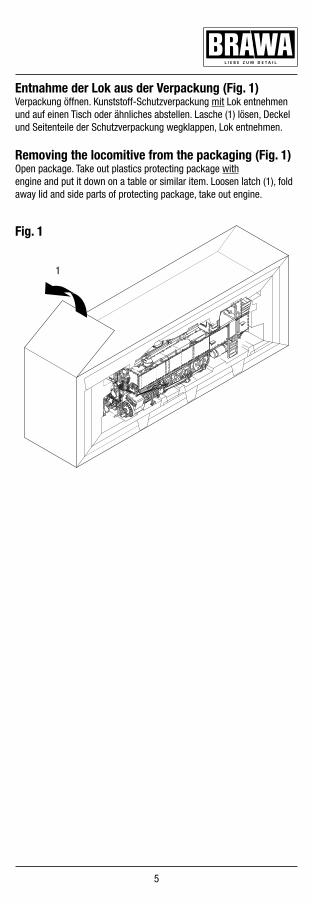
Fig. 1
Entnahme der Lok aus der Verpackung (Fig. 1)Verpackung öffnen. KunststoffSchutzverpackung mit Lok entnehmen und auf einen Tisch oder ähnliches abstellen. Lasche (1) lösen, Deckel und Seitenteile der Schutzverpackung wegklappen, Lok entnehmen.
Removing the locomitive from the packaging (Fig. 1)Open package. Take out plastics protecting package with engine and put it down on a table or similar item. Loosen latch (1), fold away lid and side parts of protecting package, take out engine.
1

6
Zusatzbauteile montieren (Fig. 2)In der Verpackung sind zusätzliche Bauteile lose beigelegt. Der Inhalt derVerpackungkannjenachVersionunterschiedlichsein.
•1=2xBremskupplung,rechts•2=2xBremskupplung,links•3=1xHeizkupplung,links•4=1xHeizkupplung,rechts•5=1xHeizkupplungsaufnahme•6=1xHaken•7=1xBremskupplungVakuumvorn•8=1xBremskupplungVakuumhinten
Fitting additional parts (Fig. 2)Accessory parts have been loosely enclosed in the packaging. The contents of the package may vary, depending on the version.
•1=2xBrakecoupling,right•2=2xBrakecoupling,left•3=1xHeatingcoupling,left•4=1xHeatingcoupling,right•5=1xHeatingcouplingadapter•6=1xHook•7=1xBrakecouplingvacuumfront•8=1xBrakecouplingvacuumback
Arbeiten vor der InbetriebnahmeWork to be performed before starting up
Fig. 2

7
1. Ölen (Fig. 3)Der Motor und die Lagerstellen der Radsätze können an den ge-kennzeichneten Punkten sparsam mit Öl der Modellbaubranche geölt werden. Zum Ölen des Motors ist das Gehäuse abzunehmen, siehe Seite 8 Punkt 2.
1. Lubricating (Fig. 3)The engine and the wheelset bearings may be sparingly lubricated at the marked places with oil used for model making purposes. In order to lubricate the engine, remove the housing, compare page 8, item 2.
Fig. 3
MotorEngine
LokomotiveLocomotiv
WartungsarbeitenMaintenance works
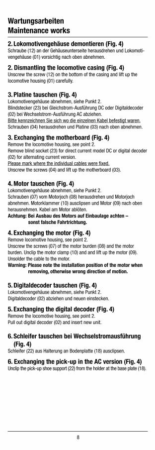
2. Lokomotivengehäuse demontieren (Fig. 4)Schraube (12) an der Gehäuseunterseite herausdrehen und Lokomoti-vengehäuse (01) vorsichtig nach oben abnehmen.
2. Dismantling the locomotive casing (Fig. 4)Unscrew the screw (12) on the bottom of the casing and lift up the locomotive housing (01) carefully.
3. Platine tauschen (Fig. 4)Lokomotivengehäuse abnehmen, siehe Punkt 2.Blindstecker (23) bei GleichstromAusführung DC oder Digitaldecoder (02) bei WechselstromAusführung AC abziehen. Bitte kennzeichnen Sie sich wo die einzelnen Kabel befestigt waren. Schrauben (04) herausdrehen und Platine (03) nach oben abnehmen.
3. Exchanging the motherboard (Fig. 4)Remove the locomotive housing, see point 2.Remove blind socket (23) for direct current model DC or digital decoder (02) for alternating current version.Please mark where the individual cables were fixed.Unscrew the screws (04) and lift up the motherboard (03).
4. Motor tauschen (Fig. 4)Lokomotivengehäuse abnehmen, siehe Punkt 2.Schrauben(07)vomMotorjoch(08)herausdrehenundMotorjochabnehmen. Motorklammer (10) ausclipsen und Motor (09) nach oben herausnehmen. Kabel am Motor ablöten.Achtung: Bei Ausbau des Motors auf Einbaulage achten – sonst falsche Fahrtrichtung.
4. Exchanging the motor (Fig. 4)Remove locomotive housing, see point 2.Unscrew the screws (07) of the motor burden (08) and the motor burden. Unclip the motor clamp (10) and and lift up the motor (09). Unsolder the cable to the motor.Warning: Please note the installation position of the motor when removing, otherwise wrong direction of motion.
5. Digitaldecoder tauschen (Fig. 4)Lokomotivengehäuse abnehmen, siehe Punkt 2.Digitaldecoder (02) abziehen und neuen einstecken.
5. Exchanging the digital decoder (Fig. 4)Remove the locomotive housing, see point 2. Pull out digital decoder (02) and insert new unit.
6. Schleifer tauschen bei Wechselstromausführung (Fig. 4)Schleifer (22) aus Halterung an Bodenplatte (18) ausclipsen.
6. Exchanging the pickup in the AC version (Fig. 4)Unclip the pick-up shoe support (22) from the holder at the base plate (18).
WartungsarbeitenMaintenance works
8

9
7. Beleuchtungseinrichtung (Fig. 4)Diese Lokomotive ist mit wartungsfreien Leuchtdioden ausgestattet. Bei einem eventuellen Defekt der Leuchtdioden wenden Sie sich bitte an Ihren Fachhändler oder den Hersteller.
7. Light fittings (Fig. 4)This locomotive is fitted with maintenancefree lightemitting diodes. If a defect occurs in the lightemitting diodes, please contact your specialist dealer or the manufacturer.
8. Kupplungsnormschacht an Lokomotive tauschen (Fig. 4)Schleifer abnehmen, siehe Punkt 6.Bremsgestänge (19) und Entwässerung (21) abnehmen. Schrauben (20) der Bodenplatte (18) herausdrehen und Bodenplatte abnehmen.Vorne: Schrauben (17) der Zylinder (16) herausdrehen und Zylinder ab-nehmen. Feder (15) aushängen. Kupplungsnormschacht (14) abnehmen und Bügelkuppplung (13) ausclipsen.Hinten: Feder (15) aushängen. Kupplungsnormschacht (14) abnehmen und Bügelkuppplung (13) ausklipsen.
8. Exchanging the standard coupling shaft on the locomotive (Fig. 4)Remove the pic-up, see point 6. Remove brake linkage (19) and drainage (21). Unscrew the screws (20) of the base plate (18) and remove base plate.Front: Unsrew the srews (17) of the cylinder (16) and remove the cy-linder. Put up the spring (15). Remove the standard coupling shaft (14) and unclip the bow coupling (13).Back: Put up the spring (15). Remove the standard coupling shaft (14) and unclip the bow coupling (13).
9. Raucheinsatz Seuthe Nr. 20 montieren (Fig. 4)Lokomotivengehäuse abnehmen, siehe Punkt 2.Raucheinsatz (Pos. 11, BestellNr. 0005069.00) an die vorhandenen Kabel anlöten und einsetzen. Gehäuse montieren.
9. Mounting smoke insert Seuthe No. 20 (Fig. 4)Remove the locomotive housing, see point 2. Solder the smoke unit (item 11, Order No. 0005069.00) at the existent cable and insert the unit. Fit housing.
10. Lautsprecher tauschen (Fig. 4)Lokomotivengehäuse abnehmen, siehe Punkt 2.Schrauben (05) herausdrehen, Platine (24) abnehmen und Lautsprecher (06) nach oben abnehmen.
10. Exchanging the speaker (Fig. 4)Remove the locomotive housing, see point 2. Unscrew the screws (05), remove the pcb (24) and lift up the speaker (06).

11. Wartungsarbeiten an Radsätze und Getriebe (Fig. 4)Bei Wartungsarbeiten an den Radsätzen, dem Kuppelgestänge und dem Getriebe muss das gesamte Fahrgestell zerlegt werden. Wir bitten Sie bei der Demontage des Fahrgestells genau darauf zu achten, wo und wiejedesEinzelteilmontiertwar. Die Einbau lage können Sie auch aus der Ersatzteilgrafik Seite 13 bis 15 ersehen. Für Beschädigungen, die durch unsachgemäße Arbeiten an den Bauteilen entstehen, kann die Firma BRAWA nicht haftbar gemacht werden.
11. Maintenance work on the wheel sets and gears (Fig. 4)When performing maintenance work on the wheel sets, the coupling rods and the gears, the whole chassis must be dismantled. We would remind you to note exactly where and how each part was assembled before dismantling the chassis. The installation position can be seen in the spare parts chart on pages 13 to 15. BRAWA is not liable for dama-ge which occurs due to improper work on construction parts.
12. Umrüsten auf Digitalbetrieb
GleichstromAusführungLokomotivengehäuse (01) abnehmen, Blindstecker (23) abziehen und Digital decoder (02) in die Schnittstelle auf der Platine (03) einstecken.Den richtigen Einbau des Digitaldecoders und dessen Einsteckrichtung entnehmen Sie der Einbauvorschrift des Decoderherstellers.
WechselstromAusführungLokomotiven in WechselstromAusführung AC werden serienmäßig mit Digitaldecoder (02) ausge liefert. Soll der Decoder umprogramiert werden, liegt die Einbau und Betriebsanleitung Digitaldecoder bei.
Der Decoder ist Werkseitig auf Adresse 03 eingestellt.
12. Converting to digital operation
DC versionRemove locomotive housing (01), pull off dummy connector (23) and insert digital decoder (02) into the serial interface at the pcb (03).Please consult the installation instructions issued by the decoder manufacturer for correct installation of the digital decoder and its insert direction.
AC versionThe digital decoder (02) is standard for the alternating current (AC) locomotives models. Please refer to the enclosed installation and opera-tion instructions “Digital Decoder” in the event that the decoder needs to be reprogrammed.
The decoder is set to address 03 in the factory.
10
WartungsarbeitenMaintenance works

11
WartungsarbeitenMaintenance works
Fig. 4

12
Funktionstastenbelegung für SoundmodelleFunction keys for sound models
Sounddecoder SD22-4 (DCC/SX1/SX2/Motorola®/DC/AC)Ausführung EXTRA / Version EXTRABRAWA-Nr.: 0014765.14Funktion /Function
Beschreibung /Description
Mapping-CV Lautsärke-CV /Volume-CV
Anmerkung /Note
F0 Hauptlicht EIN/AUSMain light ON/OFF
LV/LR(+AUX2)
3334328 348
mit Fahrtrichtung wechselnd, nur 2x bzw. 3x weiß vorne, 2x weißhinten/withdirectionchange,just2xor3xwhitefront,2x white backdas 3. Spitzenlicht vorn (wenn vorhanden) liegt über einen Schalter an AUX2 / the 3rd leading light in front (if available) is connected to AUX2 via a switch
F1 Hauptfahrgeräusch EIN/AUS /Main driving noise ON/OF
311312
331332
mit Zufallsfunktion für bestimmte Geräusche /with random function for specific sounds
F2 Pfeife kurz EIN/AUS ohne Fkt. /Whistle short ON/OFF w/o fct.
315 335
F3 Pfeife lang EIN/AUS ohne Fkt. /Whistle long ON/OFF w/o fct
316 336
F4 Rangiergang EIN/AUS /Shunting mode ON/OFF
LV+LR 38121
RangierlichtalleweißenLampenjeSeite/Shunting lights all white lights on each side
F5 Licht vorn (Kessel) AUS /Light front (boiler) OFF
LV (+AUX2) 113 AUX2 ist über Bedingungen gesteuert /AUX2 is controlled by conditions
F6 Licht hinten (Tender) AUS /Light back (tender) OFF
LR 114
F7 Rauchgenerator / Smoke generator AUX1F8 Ausblenden vom Sound / Fading of sound 329 349F9 Pfeife lang alternativ EIN/AUS o. Fkt. /
Whistle long alternative ON/OFF w/o fc317 337
F10 Injektor(Dampfstrahlspeisepumpe)/Injektor(steamjetfeedpump)
321 341
F11 Luftpumpe (langsam) / Air pump (slow) 319 339F12 Luftpumpe (schnell) / Air pump (fast) 320 340F13 Kohlen schaufeln / Coal shovel 318 338F14 Ausblasen der Zylinder (Zylinderhähne) /
Blowing out of the cylinder (cylinder tap)324 344
F15 Sicherheitsventil / Safety valve 323 343F16 Abschlammen / Blow down 322 342F17 Schaffnerpfiff / Conductor's whistle 325 345F18 Kupplungsgeräusch + Luft /
Coupling sound+Air326 346
F19 Bremsgeräusch / Brake sound 314 334F20 Leerlauf erzwingen / Force idle 377F21 Bremsgeräusch deaktivieren /
Brake sound deactivated376
F22 Lautstärke verringern / Decrease volume 374F23 Lautstärke erhöhen / Increase volume 375
Funktion /Function
Beschreibung /Description
Mapping-CV Anmerkung /Note
F0 Hauptlicht EIN/AUS /Main light ON/OFF
LV/LR 3334
mit Fahrtrichtung wechselnd, nur 2x bzw. 3x weiß vorne, 2x weiß hinten / with directionchange,just2xor3xwhitefront,2xwhitebackdas 3. Spitzenlicht vorn (wenn vorhanden) kann über einen Schalter an AUX2 ge-legt und gesondert geschaltet werden/ the 3rd leading light in front (if available) can be connected to AUX2 via a switch and switched separately
F1 Licht vorn (Kessel) AUS /Light front (boiler) OFF
LV 113
F2 Licht hinten (Tender) AUS / Light back (tender) OFF
LR 114
F3 Rauchgenerator / Smoke generator AUX1 not installed in locomotiveF4 Rangiergang EIN/AUS /
Shunting mode ON/OFFLV/LR 38
121RangierlichtalleweißenLampenjeSeite/Shunting lights all white lights on each side
Decoder ohne Sound / Decoder w/o sound DH22-4 (DCC/SX1/SX2/Motorola®/DC/AC)Ausführung Basic+ / Version Basic+BRAWA-Nr.: 0014764.02
Motorola® ist ein eingetragenes Warenzeichen der Firma Motorola Inc., Schaumburg, Illinois, USA.

Funktion /Function
Beschreibung /Description
Mapping-CV Lautsärke-CV /Volume-CV
Anmerkung /Note
F0 Hauptlicht EIN/AUSMain light ON/OFF
LV/LR(+AUX2)
3334328 348
mit Fahrtrichtung wechselnd, nur 2x bzw. 3x weiß vorne, 2x weißhinten/withdirectionchange,just2xor3xwhitefront,2x white backdas 3. Spitzenlicht vorn (wenn vorhanden) liegt über einen Schalter an AUX2 / the 3rd leading light in front (if available) is connected to AUX2 via a switch
F1 Hauptfahrgeräusch EIN/AUS /Main driving noise ON/OF
311312
331332
mit Zufallsfunktion für bestimmte Geräusche /with random function for specific sounds
F2 Pfeife kurz EIN/AUS ohne Fkt. /Whistle short ON/OFF w/o fct.
315 335
F3 Pfeife lang EIN/AUS ohne Fkt. /Whistle long ON/OFF w/o fct
316 336
F4 Rangiergang EIN/AUS /Shunting mode ON/OFF
LV+LR 38121
RangierlichtalleweißenLampenjeSeite/Shunting lights all white lights on each side
F5 Licht vorn (Kessel) AUS /Light front (boiler) OFF
LV (+AUX2) 113 AUX2 ist über Bedingungen gesteuert /AUX2 is controlled by conditions
F6 Licht hinten (Tender) AUS /Light back (tender) OFF
LR 114
F7 Rauchgenerator / Smoke generator AUX1F8 Ausblenden vom Sound / Fading of sound 329 349F9 Pfeife lang alternativ EIN/AUS o. Fkt. /
Whistle long alternative ON/OFF w/o fc317 337
F10 Injektor(Dampfstrahlspeisepumpe)/Injektor(steamjetfeedpump)
321 341
F11 Luftpumpe (langsam) / Air pump (slow) 319 339F12 Luftpumpe (schnell) / Air pump (fast) 320 340F13 Kohlen schaufeln / Coal shovel 318 338F14 Ausblasen der Zylinder (Zylinderhähne) /
Blowing out of the cylinder (cylinder tap)324 344
F15 Sicherheitsventil / Safety valve 323 343F16 Abschlammen / Blow down 322 342F17 Schaffnerpfiff / Conductor's whistle 325 345F18 Kupplungsgeräusch + Luft /
Coupling sound+Air326 346
F19 Bremsgeräusch / Brake sound 314 334F20 Leerlauf erzwingen / Force idle 377F21 Bremsgeräusch deaktivieren /
Brake sound deactivated376
F22 Lautstärke verringern / Decrease volume 374F23 Lautstärke erhöhen / Increase volume 375
Funktion /Function
Beschreibung /Description
Mapping-CV Anmerkung /Note
F0 Hauptlicht EIN/AUS /Main light ON/OFF
LV/LR 3334
mit Fahrtrichtung wechselnd, nur 2x bzw. 3x weiß vorne, 2x weiß hinten / with directionchange,just2xor3xwhitefront,2xwhitebackdas 3. Spitzenlicht vorn (wenn vorhanden) kann über einen Schalter an AUX2 ge-legt und gesondert geschaltet werden/ the 3rd leading light in front (if available) can be connected to AUX2 via a switch and switched separately
F1 Licht vorn (Kessel) AUS /Light front (boiler) OFF
LV 113
F2 Licht hinten (Tender) AUS / Light back (tender) OFF
LR 114
F3 Rauchgenerator / Smoke generator AUX1 not installed in locomotiveF4 Rangiergang EIN/AUS /
Shunting mode ON/OFFLV/LR 38
121RangierlichtalleweißenLampenjeSeite/Shunting lights all white lights on each side
Decoder ohne Sound / Decoder w/o sound DH22-4 (DCC/SX1/SX2/Motorola®/DC/AC)Ausführung Basic+ / Version Basic+BRAWA-Nr.: 0014764.02
Motorola® is a registered trademark ofMotorola Inc., Schaumburg, Illinois, USA.
13

Zusatzinformationen /Additional informations
Die Lok ist mit einer PluX22-Schnittstelle mit eingeschränktem Einbau-raum ausgestattet. Die maximale Einbaulänge des Decoders beträgt in dieser Lok 27 mm. Bitte prüfen Sie vor dem Einbau eines Decoders diese Abmessung und verwenden Sie gegebenfalls kleinere Decoder. Wir empfehlen die Verwendung der Decoder DH22 bzw. SD22 von Doehler&Haass (aktuelle Ausführung).Die Lok ist im Digitalbetrieb auf die Betriebsart DCC mit der Adresse 3 eingestellt.In der analogen Basic+ - Ausführung ist ein Lichtwechsel mit weißen LEDvorhanden(3xweißbzw.2xweißjenachModell).In allen Ausführungen kann über einen Schiebeschalter (siehe Fig. 5) bei Bedarf und Vorhandensein das 3. Frontlicht zwischen LV (F0f) und AUX2 umgeschaltet werden. Damit kann das 3. Frontlicht auch als Sondersignal genutzt werden.Die "Basic+"- Ausführungen (DC mit Analogstecker und AC mit Stan-darddecoder) haben eine Belegung der Funktionen F1 bis F4.Die "Extra"- Ausführungen (alle Soundversionen) haben eine Belegung der Funktionen F1 bis F23.
The locomotive is equipped with a PluX22 interface with limited installation space. The maximum installation length of the decoder in this locomotive is 27 mm. Please check this dimension before installing a decoder and use smaller decoders if necessary. We recommend using the decoders DH22 or SD22 from Doehler & Haass (current version).The locomotive is set to DCC mode with address 3 in digital mode.In the analog Basic+ version there is a light change with white LED (3x white or 2x white depending on the model).In all versions, the 3rd front light between LV (F0f) and AUX2 can be switched over with a slide switch (see fig. 5) if required and available. So that the 3rd front light can also be used as a special signal.The "Basic +" versions (DC with analog plug and AC with standard decoder) have an assignment of the functions F1 to F4.The "Extra" versions (all sound versions) have an assignment of the functions F1 to F23.
CV Wert /Value
Beschreibung /Description
13 0 Analogbetrieb ohne F1 / Analog operation without F133 1 Lichtwechsel vorwärts (LV) / Light change forward (LV)34 2 Lichtwechsel rückwärts (LR) / Light change backwards (LR)
35 0 keine Einschaltfunktion mit F1 / no switch-on function with F136 0 keine Einschaltfunktion mit F2 / no switch-on function with F237 4 F3 an AUX1 (für Rauchgenerator) /
F3 to AUX1 (for smoke generator)39 0 F5 ohne Funktion / F5 without function47 0 wie CV35, sollte sich automatisch anpassen /
like CV35, should adapt automatically64 0 wie CV36, sollte sich automatisch anpassen /
like CV36, should adapt automatically113 1 Ausschaltfunktion F1 (LV) / Switch-off function F1 (LV)114 2 Ausschaltfunktion F2 (LR) / Switch-off function F2 (LR)121 8 Rangierlicht bei F4 (LV+LR) / Shunting light at F4 (LV+LR)
Fig. 5
Mapping-Empfehlung für den Fahrdecoder DH22Mapping recommendation for the driving decoder DH22
14

15
ErsatzteillisteSpare parts list

101
78
23
107
7829
39
30 31
225
78
1314
102
64
117374 111
12373
48
85
124133
11
1225348 127
228
231
227
100
90
40
45
91
228
101
90231
232 100
230
40 236
ErsatzteillisteSpare parts list
16

17

ErsatzteillisteSpare Parts List
18
Artikelnummer/Article number
Pos. Bennenung DescriptionBestell Nr.Order no. 40
792
4079
4
4079
6
4079
8
01 Handrad Rauchkammertür Konterhebel Boiler front opening lever 0003412.00 – – • •0003412.04 • • – –
02 Kurbelbolzen Valve gear pin 0003505.03 • • • •03 Kurbelzapfen 1 Crankpin 1 0006938.02 • • • •04 Treibstange Connecting rod 0007162.05 • • – –
0007162.06 – – • •05 Handrad Rauchkammertür Handwheel of smokebox door 0007270.04 • • – –06 Gleitbahn Slipway 0007164.02 • • • •07 Kreuzkopf Crosshead 0007165.02 • • • •08 Kolbenstange Piston rod 0007166.00 • • • •09 Gegenkurbel Eccentric crane 0007167.02 • • • •10 Schwingenhebel Lever 0007168.02 • • • •11 Halter Schwinghebel Holder of lever 0007169.00 • • • •12 Kreuzkopfhebel Crosshead lever 0007170.02 • • • •13 Lautsprecher Loudspeaker 0015796.00 – • – •14 Dampfgenerator Nr. 20 Smoking box Nr. 20 0005069.00 – • – •18 Kuppelstange hinten rechts Coupling rod back right 0007171.02 • • • •19 Kuppelstange vorn rechts Coupling rod front right 0007172.02 • • • •20 Griff RKT Grasp of smokebox door 0007271.00 • • • •22 Sounddecoder Sounddecoder 0014765.14 – • – •23 Motorträger Engine bearer 0007175.00 • • • •29 Zylinderschraube Cylinder head screw 0007360.00 • • • •30 Passschraube Fit bolt 0007180.00 • • • •31 Motorklammer Motor clamp 0007181.00 • • • •33 Zylinderschraube Cylinder head screw 0007154.00 • • • •39 Senkschraube Vertical head screw 0007156.00 • • • •40 Zugfeder Kinematik Spring coupler socket 0003589.00 • • • •45 Senkschraube Vertical head screw 0007359.00 • • • •46 Kolbenstangenschutz Protection piston rod 0007186.00 • • • •48 Griff Pufferbohle Grasp buffer beam 0007189.00 • • • •53 Bremsleitung vorn Brake conduit front 0007301.00 • • • •61 Schwingenstange rechts Lever rod right 0007197.02 • • • •62 Schwinghebel 2 Lever 2 0007198.02 • • • •64 Schwinghebelachse Lever pivot 0007200.00 • • • •65 Schieberschutzrohr Slider protective tube 0007201.00 • • • •66 Schieberkreuzkopf rechts Slider crosshead right 0007202.02 • • • •67 Schiebergleitbahn Slider slipway 0007203.00 • • • •68 Schieberstange Slider rod 0007204.00 • • • •69 Voreilhebel rechts Control lever right 0007205.02 • • • •70 Lenkerstange Steering rod 0007206.02 • • • •71 Stütze Strut 0007207.00 • • • •72 Schieberschubstange Slider push rod 0007208.02 • • • •73 Schieberträger Slider bearer 0007209.00 • • • •74 Steuerwellenlager Steering wheel shaft bearings 0007210.00 • • • •75 Steuerwelle Control shaft 0007211.00 • • • •76 Aufwerfhebel rechts Lifting lever 0007212.00 • • • •78 Zylinderschraube Cylinder head screw 0007361.00 • • • •79 Bodenplatte Floor plate 0007214.00 • • • •82 Schleiferkontakt Wiper contact – – – – –83 Hohlniet Hollow rivet – – – – –73 Schieberträger Slider bearer 0007209.00 • • • •
0007209.01 – – – –74 Steuerwellenlager Steering wheel shaft bearings 0007210.00 • • • •
0007210.01 – – – –75 Steuerwelle Control shaft 0007211.00 • • • •
0007211.01 – – – –76 Aufwerfhebel rechts Lifting lever 0007212.00 • • • •
0007212.01 – – – –78 Zylinderschraube Cylinder head screw 0007361.00 • • • •79 Bodenplatte Floor plate 0007214.00 • • • •
0007214.02 – – – –82 Schleiferkontakt Wiper contact 0006914.00 • • • •83 Hohlniet Hollow rivet 0007160.00 • • • •

19
Artikelnummer/Article number
Pos. Bennenung DescriptionBestell Nr.Order no. 40
792
4079
4
4079
6
4079
8
01 Handrad Rauchkammertür Konterhebel Boiler front opening lever 0003412.00 – – • •0003412.04 • • – –
02 Kurbelbolzen Valve gear pin 0003505.03 • • • •03 Kurbelzapfen 1 Crankpin 1 0006938.02 • • • •04 Treibstange Connecting rod 0007162.05 • • – –
0007162.06 – – • •05 Handrad Rauchkammertür Handwheel of smokebox door 0007270.04 • • – –06 Gleitbahn Slipway 0007164.02 • • • •07 Kreuzkopf Crosshead 0007165.02 • • • •08 Kolbenstange Piston rod 0007166.00 • • • •09 Gegenkurbel Eccentric crane 0007167.02 • • • •10 Schwingenhebel Lever 0007168.02 • • • •11 Halter Schwinghebel Holder of lever 0007169.00 • • • •12 Kreuzkopfhebel Crosshead lever 0007170.02 • • • •13 Lautsprecher Loudspeaker 0015796.00 – • – •14 Dampfgenerator Nr. 20 Smoking box Nr. 20 0005069.00 – • – •18 Kuppelstange hinten rechts Coupling rod back right 0007171.02 • • • •19 Kuppelstange vorn rechts Coupling rod front right 0007172.02 • • • •20 Griff RKT Grasp of smokebox door 0007271.00 • • • •22 Sounddecoder Sounddecoder 0014765.14 – • – •23 Motorträger Engine bearer 0007175.00 • • • •29 Zylinderschraube Cylinder head screw 0007360.00 • • • •30 Passschraube Fit bolt 0007180.00 • • • •31 Motorklammer Motor clamp 0007181.00 • • • •33 Zylinderschraube Cylinder head screw 0007154.00 • • • •39 Senkschraube Vertical head screw 0007156.00 • • • •40 Zugfeder Kinematik Spring coupler socket 0003589.00 • • • •45 Senkschraube Vertical head screw 0007359.00 • • • •46 Kolbenstangenschutz Protection piston rod 0007186.00 • • • •48 Griff Pufferbohle Grasp buffer beam 0007189.00 • • • •53 Bremsleitung vorn Brake conduit front 0007301.00 • • • •61 Schwingenstange rechts Lever rod right 0007197.02 • • • •62 Schwinghebel 2 Lever 2 0007198.02 • • • •64 Schwinghebelachse Lever pivot 0007200.00 • • • •65 Schieberschutzrohr Slider protective tube 0007201.00 • • • •66 Schieberkreuzkopf rechts Slider crosshead right 0007202.02 • • • •67 Schiebergleitbahn Slider slipway 0007203.00 • • • •68 Schieberstange Slider rod 0007204.00 • • • •69 Voreilhebel rechts Control lever right 0007205.02 • • • •70 Lenkerstange Steering rod 0007206.02 • • • •71 Stütze Strut 0007207.00 • • • •72 Schieberschubstange Slider push rod 0007208.02 • • • •73 Schieberträger Slider bearer 0007209.00 • • • •74 Steuerwellenlager Steering wheel shaft bearings 0007210.00 • • • •75 Steuerwelle Control shaft 0007211.00 • • • •76 Aufwerfhebel rechts Lifting lever 0007212.00 • • • •78 Zylinderschraube Cylinder head screw 0007361.00 • • • •79 Bodenplatte Floor plate 0007214.00 • • • •82 Schleiferkontakt Wiper contact – – – – –83 Hohlniet Hollow rivet – – – – –73 Schieberträger Slider bearer 0007209.00 • • • •
0007209.01 – – – –74 Steuerwellenlager Steering wheel shaft bearings 0007210.00 • • • •
0007210.01 – – – –75 Steuerwelle Control shaft 0007211.00 • • • •
0007211.01 – – – –76 Aufwerfhebel rechts Lifting lever 0007212.00 • • • •
0007212.01 – – – –78 Zylinderschraube Cylinder head screw 0007361.00 • • • •79 Bodenplatte Floor plate 0007214.00 • • • •
0007214.02 – – – –82 Schleiferkontakt Wiper contact 0006914.00 • • • •83 Hohlniet Hollow rivet 0007160.00 • • • •

20
ErsatzteillisteSpare Parts List
Artikelnummer/Article number
Pos. Bennenung DescriptionBestell Nr.Order no. 40
792
4079
4
4079
6
4079
8
84 Bremgestänge Brake rod 0007215.00 • • • •85 Senkschraube Vertical head screw 0003560.00 • • • •90 Schienenräumer 1 Cowcatcher 1 0007302.00 • • • •91 Schienenräumer 2 Cowcatcher 2 0007303.00 • • • •96 Entwässerung rechts Drainage right 0007223.00 • • • •97 Entwässerung links Drainage links 0007224.00 • • • •98 Entwässerungswelle Drainage shaft 0007225.00 • • • •99 Sandfallrohr vorn rechts Sandy soil pipe right 0007226.00 • • • •100 Rangiergriff Maneuvering handle 0007227.00 • • • •101 Tritt Pufferbohle Occurs buffer baems 0007228.00 • • • •102 Luftleitung rechts Air pipe right 0007304.00 • • • •106 Lampenhalter hinten Rear lamp holder 0007229.00 • • • •107 PCB ana./dig. B+/E 2L/3L (Rh178) PCB ana./dig. B+/E 2L/3L (Rh178) 0020446.00 • • • •108 Kuppelstange vorn links Dome rod front left 0007231.02 • • • •109 Kuppelstange hinten links Dome rod rear left 0007232.02 • • • •110 Kreuzkopfhebel links Crosshead lever left 0007233.02 • • • •111 Aufwerfhebel links Lifting lever left 0007234.00 • • • •112 Schieberkreuzkopf links Slide crosshead left 0007235.02 • • • •113 Voreilhebel links Control lever 0007236.02 • • • •114 Schwingenstange links Swing bar left 0007237.02 • • • •122 Deckel Ölpumpe Cover of oil pump 0007312.00 • • • •123 Schwinghebelachse Pivot lever 0007313.00 • • • •124 Handkurbel Ölpumpe Crank handle oil pump 0007314.00 • • • •127 E-Leitung E-line 0007329.00 • • • •133 Kurbel Ölpumpe 2 Crank oil pump 2 0007342.00 • • • •135 Leiter Ladder 0007251.00 • • • •136 Griffstange Aufstieg kurz Handrail stair short 0007252.00 • • • •138 Haken Wasserkasten Hook radiator tank 0007255.00 • • • •144 Auftritt Wasserkasten Stair radiator tank 0007317.00 • • • •145 Griffstange Führerhausaufstieg Handrail driver's cab stair 0007284.00 – – • •146 Griffstange Seitenfenster Handrail side window 0007283.00 • • • •147 Griffstange Führerhausaufstieg 9 Handrail driver's cab stair 9 0007901.00 • • – –150 Haken Hook 0003605.00 • • • •151 Pfeife Whistle 0003580.00 • • • •161 Sicherheitsventil Dampfdom Safety valve of steam dome 0007264.00 • • • •162 Hebel Sandkasten Sandbox lever 0007265.00 • • • •163 Sandfallrohr 1 Sand pipe 1 0007266.00 • • • •164 Anbauteil Kessel Attachment part of bowl 0007268.00 • • • •166 Sandzug kpl. links Sand pipe left cpl. 0010027.00 • • • •167 Sandzug kpl. rechts Sand pipe right cpl. 0010026.00 • • • •172 Luftpumpenträger 2 Pump peg 2 0007319.00 • • • •173 Luftpumpe zweistufig Pump 0007072.00 – – • •174 Luftpumpe Luftleitung Air pump air pipe 0007321.00 – – • •175 Luftpumpe Luftleitung 178 2 Air pump air pipe 178 2 0007322.00 • • • •176 Schlauchschelle 2 Hose clamp 2 0007323.00 • • • •177 Halter Lichtmaschine Holder of alternator 0007334.00 • • • •178 Lichtmaschine Alternator 0006884.00 • • • •179 Schornstein Pruessmann Luftpumpe Chimney Pruessmann air pump – – – – –180 Luftpumpe Dampfleitung 2 Air pump steam pipe 2 – – – – –181 E-Leitung Lima 2 Electric line alternator 2 0007349.00 • • – –182 Sandfallrohr 2 Sand pipe 2 0007350.00 • • – –183 Frischdampfleitung Lima 2 Live steam alternator 2 0007351.00 • • – –184 Lampenahalter Kessel Lamp holder bowl 0007324.00 • • • •189 Vakuumpumpe Vacuum pump 0007267.00 • • • •190 Abdampfleitung Lima 2 Exhaust steam pipe alternator 2 0007353.00 • • – –192 Reglerzug Hand stop of controler 0007292.00 • • • •193 Hebel Regler Lever of controler 0007293.00 • • • •194 Griffstange Aufstieg lang Handrail stair long 0007290.00 • • • •195 Rohr Vakuum Bremse Pipe vacuum brake 0007291.00 • • • •197 Senkschraube Vertical head screw 0007157.00 • • • •200 Frischdampfleitung Lima 178 Live steam pipe alternator 178 0007338.00 – – • •201 Griff RKT 2Türer Grip smokebox 2 doors – – – – –202 Luftpumpe Luftleitung gekürzt Air pump air pipe 0007891.00 • • – –

21
Artikelnummer/Article number
Pos. Bennenung DescriptionBestell Nr.Order no. 40
792
4079
4
4079
6
4079
8
84 Bremgestänge Brake rod 0007215.00 • • • •85 Senkschraube Vertical head screw 0003560.00 • • • •90 Schienenräumer 1 Cowcatcher 1 0007302.00 • • • •91 Schienenräumer 2 Cowcatcher 2 0007303.00 • • • •96 Entwässerung rechts Drainage right 0007223.00 • • • •97 Entwässerung links Drainage links 0007224.00 • • • •98 Entwässerungswelle Drainage shaft 0007225.00 • • • •99 Sandfallrohr vorn rechts Sandy soil pipe right 0007226.00 • • • •100 Rangiergriff Maneuvering handle 0007227.00 • • • •101 Tritt Pufferbohle Occurs buffer baems 0007228.00 • • • •102 Luftleitung rechts Air pipe right 0007304.00 • • • •106 Lampenhalter hinten Rear lamp holder 0007229.00 • • • •107 PCB ana./dig. B+/E 2L/3L (Rh178) PCB ana./dig. B+/E 2L/3L (Rh178) 0020446.00 • • • •108 Kuppelstange vorn links Dome rod front left 0007231.02 • • • •109 Kuppelstange hinten links Dome rod rear left 0007232.02 • • • •110 Kreuzkopfhebel links Crosshead lever left 0007233.02 • • • •111 Aufwerfhebel links Lifting lever left 0007234.00 • • • •112 Schieberkreuzkopf links Slide crosshead left 0007235.02 • • • •113 Voreilhebel links Control lever 0007236.02 • • • •114 Schwingenstange links Swing bar left 0007237.02 • • • •122 Deckel Ölpumpe Cover of oil pump 0007312.00 • • • •123 Schwinghebelachse Pivot lever 0007313.00 • • • •124 Handkurbel Ölpumpe Crank handle oil pump 0007314.00 • • • •127 E-Leitung E-line 0007329.00 • • • •133 Kurbel Ölpumpe 2 Crank oil pump 2 0007342.00 • • • •135 Leiter Ladder 0007251.00 • • • •136 Griffstange Aufstieg kurz Handrail stair short 0007252.00 • • • •138 Haken Wasserkasten Hook radiator tank 0007255.00 • • • •144 Auftritt Wasserkasten Stair radiator tank 0007317.00 • • • •145 Griffstange Führerhausaufstieg Handrail driver's cab stair 0007284.00 – – • •146 Griffstange Seitenfenster Handrail side window 0007283.00 • • • •147 Griffstange Führerhausaufstieg 9 Handrail driver's cab stair 9 0007901.00 • • – –150 Haken Hook 0003605.00 • • • •151 Pfeife Whistle 0003580.00 • • • •161 Sicherheitsventil Dampfdom Safety valve of steam dome 0007264.00 • • • •162 Hebel Sandkasten Sandbox lever 0007265.00 • • • •163 Sandfallrohr 1 Sand pipe 1 0007266.00 • • • •164 Anbauteil Kessel Attachment part of bowl 0007268.00 • • • •166 Sandzug kpl. links Sand pipe left cpl. 0010027.00 • • • •167 Sandzug kpl. rechts Sand pipe right cpl. 0010026.00 • • • •172 Luftpumpenträger 2 Pump peg 2 0007319.00 • • • •173 Luftpumpe zweistufig Pump 0007072.00 – – • •174 Luftpumpe Luftleitung Air pump air pipe 0007321.00 – – • •175 Luftpumpe Luftleitung 178 2 Air pump air pipe 178 2 0007322.00 • • • •176 Schlauchschelle 2 Hose clamp 2 0007323.00 • • • •177 Halter Lichtmaschine Holder of alternator 0007334.00 • • • •178 Lichtmaschine Alternator 0006884.00 • • • •179 Schornstein Pruessmann Luftpumpe Chimney Pruessmann air pump – – – – –180 Luftpumpe Dampfleitung 2 Air pump steam pipe 2 – – – – –181 E-Leitung Lima 2 Electric line alternator 2 0007349.00 • • – –182 Sandfallrohr 2 Sand pipe 2 0007350.00 • • – –183 Frischdampfleitung Lima 2 Live steam alternator 2 0007351.00 • • – –184 Lampenahalter Kessel Lamp holder bowl 0007324.00 • • • •189 Vakuumpumpe Vacuum pump 0007267.00 • • • •190 Abdampfleitung Lima 2 Exhaust steam pipe alternator 2 0007353.00 • • – –192 Reglerzug Hand stop of controler 0007292.00 • • • •193 Hebel Regler Lever of controler 0007293.00 • • • •194 Griffstange Aufstieg lang Handrail stair long 0007290.00 • • • •195 Rohr Vakuum Bremse Pipe vacuum brake 0007291.00 • • • •197 Senkschraube Vertical head screw 0007157.00 • • • •200 Frischdampfleitung Lima 178 Live steam pipe alternator 178 0007338.00 – – • •201 Griff RKT 2Türer Grip smokebox 2 doors – – – – –202 Luftpumpe Luftleitung gekürzt Air pump air pipe 0007891.00 • • – –

ErsatzteillisteSpare Parts List
22
Artikelnummer/Article number
Pos. Bennenung DescriptionBestell Nr.Order no. 40
792
4079
4
4079
6
4079
8
203 Handlauf Wasserkasten rechts + links Handle water tank right + left – – – – –204 Blindstecker Blind plug – – – – –204 Analogstecker Analogue plug 0020443.00 • – • –206 Schornstein mit Kobel kpl. Chimney cpl. – – – – –207 Rohr vorn rechts Pipe front right 0007294.00 – – • •208 Abdampfleitung Lima 1 Exhaust steam pipe alternator 1 0007336.00 – – • •209 E-Leitung 178 Electric line178 0007337.00 – – • •210 Schornstein pruessmann Chimney pruessmann 0007335.00 – – • •211 Schornstein Pruessmann Chimney Pruessmann 0007299.00 • • – –212 Schornstein Pruessmann Luftpumpe kurz Chimney Pruessmann air pump short – – – – –213 Luftpumpe Dampfleitung 3 Air pump steam pipe 3 – – – – –217 Rauchkammertür genietet kpl. Smokebox door riveted cpl. 0010008.08 • • – –218 Rauchkammertür geschweißt kpl. Smokebox door welded cpl. 0010009.03 – – • •219 Rauchkammertür kpl. Smokebox door kpl. – – – – –220 Kurbel Ölpumpe Crank oil pump – – – – –221 Luftpumpe Dampfleitung 2 Air pump steam pipe 2 0007320.00 • • • •222 Luftpumpe Westinghouse West pump (T8) 0003532.00 • • – –223 Handlauf Wasserkasten rechts Handle water tank right 0010011.00 • • • •224 Handlauf Wasserkasten links Handle water tank left 0010012.00 • • • •225 Motor kpl. Motor cpl. 0003593.00 • • • •226 Einheitslampe kpl. mit LED Lamp cpl. with LED 0010018.00 • • – –227 Gaslampe Italien kpl. mit LED Italy gas lamp cpl. with LED – – – – –228 Gaslampe kpl. mit LED Gas lamp cpl. with LED 0010017.00 – – • •229 Schienenräumer 3 Cowcatcher 3 0007241.00 – – – –230 Schienenräumer 4 Cowcatcher 4 0007240.00 – – – –231 Stangenpuffer gewölbt kpl. Buffer right cpl. 0010015.00 – – • •232 Stangenpuffer flach kpl. Buffer left cpl. 0010016.00 – – • •233 Hülsenpuffer gewölbt kpl. Buffer new style round cpl. 0008888.04 • • – –234 Hülsenpuffer flach kpl. Buffer new style flat cpl. 0008887.04 • • – –235 Bremsrohr Vakuum vorn Vacuum brake pipe – – – – –236 Zurüstbeutel kpl. Add on part bag cpl. – – – – –
0010015.01 – – – –232 Stangenpuffer flach kpl. Buffer left cpl. 0010016.00 • • • •
0010016.01 – – – –233 Hülsenpuffer gewölbt kpl. Buffer new style round cpl. – – – – –234 Hülsenpuffer flach kpl. Buffer new style flat cpl. – – – – –235 Bremsrohr Vakuum vorn Vacuum brake pipe 0007243.00 • • – –236 Zurüstbeutel kpl. Add on part bag cpl. 0010025.00 • • • •
0010025.01 – – – –237 Kuppelradsatz kpl. Boxpok Wheelset cpl. 0010020.04 • • – –238 Treibradsatz kpl. Boxpok Wheelset cpl. 0010021.04 • • – –239 Kuppelradsatz kpl. Speichen Wheelset cpl. 0010022.00 – – • •240 Treibradsatz kpl. Speichen Wheelset cpl. 0010023.00 – – • •241 Scheifer kpl. Pic up shoe cpl. – – – – –242 Bügelkupplung kpl. Standardcoupler cpl. 0000729.00 • • • •241 Scheifer kpl. Pic up shoe cpl. – – – – –242 Bügelkupplung kpl. Standardcoupler cpl. 0000729.00 • • • •
Wichtiger Hinweis!Bei der Bestellung von Ersatzteilen muss die BestellNr. und die Be nennung angegeben werden. Ist dies nicht der Fall, kann die Bestellung nicht bearbeitet werden.
Bestellbeispiel: Position(225),Motorkpl.=0003593.00,Motorkpl.
•verfügbar/available– nicht verfügbar/not available
Ersatzteile bestellen:www.brawa.de/ersatzteileAbweichungen in Bedruckung, Farbton und Konstruktions- oder Form-änderungen gegenüber dem Original sowie unseren Werbeunterlagen behalten wir uns vor.

23
Artikelnummer/Article number
Pos. Bennenung DescriptionBestell Nr.Order no. 40
792
4079
4
4079
6
4079
8
203 Handlauf Wasserkasten rechts + links Handle water tank right + left – – – – –204 Blindstecker Blind plug – – – – –204 Analogstecker Analogue plug 0020443.00 • – • –206 Schornstein mit Kobel kpl. Chimney cpl. – – – – –207 Rohr vorn rechts Pipe front right 0007294.00 – – • •208 Abdampfleitung Lima 1 Exhaust steam pipe alternator 1 0007336.00 – – • •209 E-Leitung 178 Electric line178 0007337.00 – – • •210 Schornstein pruessmann Chimney pruessmann 0007335.00 – – • •211 Schornstein Pruessmann Chimney Pruessmann 0007299.00 • • – –212 Schornstein Pruessmann Luftpumpe kurz Chimney Pruessmann air pump short – – – – –213 Luftpumpe Dampfleitung 3 Air pump steam pipe 3 – – – – –217 Rauchkammertür genietet kpl. Smokebox door riveted cpl. 0010008.08 • • – –218 Rauchkammertür geschweißt kpl. Smokebox door welded cpl. 0010009.03 – – • •219 Rauchkammertür kpl. Smokebox door kpl. – – – – –220 Kurbel Ölpumpe Crank oil pump – – – – –221 Luftpumpe Dampfleitung 2 Air pump steam pipe 2 0007320.00 • • • •222 Luftpumpe Westinghouse West pump (T8) 0003532.00 • • – –223 Handlauf Wasserkasten rechts Handle water tank right 0010011.00 • • • •224 Handlauf Wasserkasten links Handle water tank left 0010012.00 • • • •225 Motor kpl. Motor cpl. 0003593.00 • • • •226 Einheitslampe kpl. mit LED Lamp cpl. with LED 0010018.00 • • – –227 Gaslampe Italien kpl. mit LED Italy gas lamp cpl. with LED – – – – –228 Gaslampe kpl. mit LED Gas lamp cpl. with LED 0010017.00 – – • •229 Schienenräumer 3 Cowcatcher 3 0007241.00 – – – –230 Schienenräumer 4 Cowcatcher 4 0007240.00 – – – –231 Stangenpuffer gewölbt kpl. Buffer right cpl. 0010015.00 – – • •232 Stangenpuffer flach kpl. Buffer left cpl. 0010016.00 – – • •233 Hülsenpuffer gewölbt kpl. Buffer new style round cpl. 0008888.04 • • – –234 Hülsenpuffer flach kpl. Buffer new style flat cpl. 0008887.04 • • – –235 Bremsrohr Vakuum vorn Vacuum brake pipe – – – – –236 Zurüstbeutel kpl. Add on part bag cpl. – – – – –
0010015.01 – – – –232 Stangenpuffer flach kpl. Buffer left cpl. 0010016.00 • • • •
0010016.01 – – – –233 Hülsenpuffer gewölbt kpl. Buffer new style round cpl. – – – – –234 Hülsenpuffer flach kpl. Buffer new style flat cpl. – – – – –235 Bremsrohr Vakuum vorn Vacuum brake pipe 0007243.00 • • – –236 Zurüstbeutel kpl. Add on part bag cpl. 0010025.00 • • • •
0010025.01 – – – –237 Kuppelradsatz kpl. Boxpok Wheelset cpl. 0010020.04 • • – –238 Treibradsatz kpl. Boxpok Wheelset cpl. 0010021.04 • • – –239 Kuppelradsatz kpl. Speichen Wheelset cpl. 0010022.00 – – • •240 Treibradsatz kpl. Speichen Wheelset cpl. 0010023.00 – – • •241 Scheifer kpl. Pic up shoe cpl. – – – – –242 Bügelkupplung kpl. Standardcoupler cpl. 0000729.00 • • • •241 Scheifer kpl. Pic up shoe cpl. – – – – –242 Bügelkupplung kpl. Standardcoupler cpl. 0000729.00 • • • •
Important notice!When ordering spare parts you must always state the order number and give the description. If you do not do this, the order cannot be processed.
Order example: Position(225),Motorcpl.=0003593.00,Motorcpl.
Ordering spare parts:www.brawa.de/en/sparepartsWe reserve the right to deviations in printing, color and structural or design modifications to the original as well as our advertising material.

Brawa Artur Braun Modellspielwarenfabrik GmbH & Co. KG Uferstraße 2630 · D73630 Remshalden
Hotline +49 (0)7151 979 35 68Telefax +49 (0)7151 746 62
http://www.brawa.de
24
4079
2.50
.250
/ 02
17
BR
A
Elektro und Elektronikaltgeräte dürfen nicht in den Hausmüll gelangen.SiemüssenentsprechendderjeweilsgültigenLänderrichtlinien fachgerecht entsorgt werden. Electrical equipment may not reach to domestic waste. According to the current terms of the country reference the electrical eqipment must professional disposed.
Dieses Produkt entspricht den gültigen CE Normen. This product conforms to the current CE standards.
Zum Betrieb des vorliegenden Produkts darf als Spannungsquelle nur ein nach VDE 0551/EN 60742 gefertigter SpielzeugTransformator verwendet werden.Only a toy transformer produced compliant with VDE 0551/EN 60742 may be used as a voltage source to operate this product.
Maßstabs und originalgetreue Kleinmodelle für erwachsene Sammler.
Scale and true to original smallsized model for adult collectors.