BETE 0813 Metric Catalog - Spray Nozzle · PDF fileρ Table of Contents W ith thousands of...
132
www.bete.com NOZZLES FOR INDUSTRY, POLLUTION CONTROL, AND FIRE PROTECTION
Transcript of BETE 0813 Metric Catalog - Spray Nozzle · PDF fileρ Table of Contents W ith thousands of...
www.bete.com
NOZZLES FOR INDUSTRY, POLLUTION CONTROL, AND FIRE PROTECTION

Table of Contents
With thousands of different spray nozzles available in hundreds of different materials, it’s often hard to know where to start. We’ve incorporated a number of unique chartsand other aids into this catalog to simplify your selection process.
0218Metric
Cover photography by Ed Judice and Greg Bardwell.
Payment with Visa, Mastercard and AmericanExpress accepted.
a b d
Nozzle Selection GuideHow to order
There are many ways to select a nozzle. Which way is right for you?
Do you know the spray pattern, but not the type of nozzle?..................see pages 2-4This section introduces you to the types of spray patterns and the spray nozzles available in each.
Want to see what nozzles excel at your specific application?.................see pages 5-11An alphabetical list of common applications and the nozzles that are used most frequently for each.
Still not sure? Don’t have time to look? Call us. BETE Customer Service Representatives and Applications Engineers will listen to your problem and guide you to the nozzle you need.Let our expertise save you time and keep your process running at peak efficiency.
www.bete.com
BY SPRAY PATTERN....PP. 2-4
BY APPLICATION....PP. 5-11
1-800-235-00491-413-772-0846
©2018 BETE Fog Nozzle, Inc. All rights reserved.
Follow us on Twitter
@BETE_tweets
Visit our website to search nozzlesby spray pattern, nozzle type,
material and more.Read case studies by industry tolearn why BETE solutions lead to
our customers’ success.

Alphabetical Nozzle IndexBJ ..........................................................................................54, 55CLUMP ..................................................................................103CW ......................................Full Cone: 28; Hollow Cone: 44EZ..................Full Cone: 30; Hollow Cone: 46; Fan: 66, 67FF..........................................................................................64, 65FINZ ........................................................................................117HydroClaw ............................................................................105HydroPulse ........................................................................56-59HydroWhirl Orbitor (HWO) ..............................................101HydroWhirl Poseidon (HWP) ............................................100HydroWhirl S (HWS)..............................................................99IS ..............................................................................................114L..................................................................................................73LEM ........................................................................................104LP ............................................................................................115MaxiPass (MP) ..................................................................26, 27MPL ..........................................................................................25MicroWhirl (MW)....................................................................70N ..............................................................................................106NC........................................................................................34, 35NCFL ........................................................................................38NCJ ............................................................................................49NCK ..........................................................................................37NCS............................................................................................36NF ..............................................................................................61NFD ..........................................................................................62NFS ............................................................................................63NFV............................................................................................60P..................................................................................................72PJ ................................................................................................71PSR ..........................................................................................116SAM ....................................................................................94, 95SC ........................................................................................32, 33SF ........................Full Cone: 31; Hollow Cone: 48; Fan: 68Swivel Joint (SJ)......................................................................118SpiralAir (SA) ....................................................................96, 97SPN ............................................................................................69SS................................................................................................75ST ..............................................................................................22STXP ..........................................................................................23TC ..............................................................................................39TDL ..........................................................................................112TF ........................................Full Cone: 20; Hollow Cone: 45TF29-180 ..................................................................................107TFXP ..........................................................................................21TH ........................................................................................50, 51THW ....................................................................................52, 53TurboMix (TM) ......................................................................113TW............................................................................................102Twist & Dry (TD)............................................................108-111UltiMist (UM) ..........................................................................74WL..............................................................................................24WT........................................................................................40, 41WTX ....................................................................................42, 43WTZ ..........................................................................................29XA ........................................................................................76-93
www.BETE.com
Nozzle Selection Guide ............................1-12
Alphabetical Nozzle Index..............................1
Nozzles by Spray Pattern ............................2-4
Nozzle by Application ..............................5-11
About BETE ..............................................13-16
Spray Lances and Analysis ....................17-19
Nozzles - Spray Pattern Types
Full Cone....................................................20-39
Hollow Cone ............................................40-53
Fan ..............................................................54-69
Misting ......................................................70-75
Air Atomizing ..........................................76-97
Tank Washing ........................................98-105
Special Purpose & Accessories..........106-119
Technical Information
Materials ..........................................................12
Engineering Data ..................................120-128
Conversion Data ................Inside Back Cover
Innovation is a BETE hallmark and we are proud that over 60% of the
nozzles we ship have beencustomized to meet your needs.
If you don’t see your nozzle listed,please call BETE.
Special flow rates and angles areavailable for most nozzle series.
1
Quickconnection system, ramped engagement forautomatic alignment.1/8” - 1/2” p. 30
EZ
By APPLICATIoN....PP. 5-11
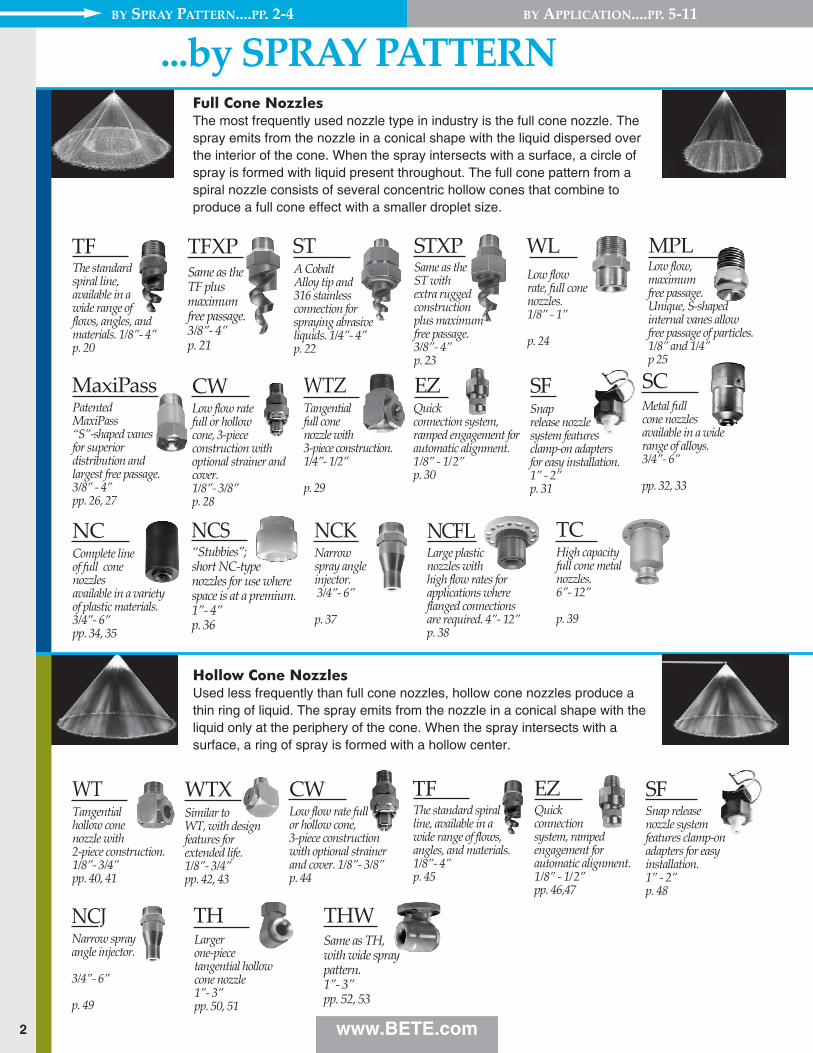
TFThe standardspiral line,available in awide range offlows, angles, and materials. 1/8”- 4” p. 20
TFXPSame as the TF plus maximum free passage.3/8”- 4” p. 21
NCFLLarge plastic nozzles withhigh flow rates forapplications whereflanged connectionsare required. 4”- 12” p. 38
NCComplete lineof full conenozzlesavailable in a varietyof plastic materials.3/4”- 6” pp. 34, 35
Narrow spray angle injector. 3/4”- 6”
p. 37
High capacityfull cone metalnozzles. 6”- 12”
p. 39
SCMetal fullcone nozzles available in a widerange of alloys. 3/4”- 6”
pp. 32, 33
WTXSimilar toWT, with designfeatures forextended life. 1/8”- 3/4”pp. 42, 43
THLarger one-piecetangential hollow cone nozzle1”- 3” pp. 50, 51
THWSame as TH,with wide spraypattern. 1”- 3”pp. 52, 53
NCS“Stubbies”;short NC-typenozzles for use wherespace is at a premium. 1”- 4” p. 36
WTZ
STXPSame as the ST with extra ruggedconstruction plus maximum free passage. 3/8”- 4” p. 23
STA Cobalt Alloy tip and 316 stainlessconnection forspraying abrasiveliquids. 1/4”- 4”p. 22
WLLow flowrate, full conenozzles. 1/8” - 1”
p. 24
CWLow flow rate fullor hollow cone, 3-piece constructionwith optional strainerand cover. 1/8”- 3/8” p. 44
WTTangentialhollow conenozzle with 2-piece construction. 1/8”- 3/4”pp. 40, 41
NCK
Tangential full cone nozzle with 3-piece construction. 1/4”- 1/2”
p. 29
...by SPrAy PATTErN
www.BETE.com
TC
CWLow flow ratefull or hollowcone, 3-piececonstruction withoptional strainer andcover. 1/8”- 3/8” p. 28
SFSnaprelease nozzle system featuresclamp-on adaptersfor easy installation. 1” - 2”p. 31
Full Cone NozzlesThe most frequently used nozzle type in industry is the full cone nozzle. Thespray emits from the nozzle in a conical shape with the liquid dispersed overthe interior of the cone. When the spray intersects with a surface, a circle ofspray is formed with liquid present throughout. The full cone pattern from aspiral nozzle consists of several concentric hollow cones that combine toproduce a full cone effect with a smaller droplet size.
MaxiPassPatentedMaxiPass“S”-shaped vanesfor superiordistribution andlargest free passage.3/8” - 4”pp. 26, 27
MPLLow flow,maximumfree passage. Unique, S-shapedinternal vanes allowfree passage of particles.1/8” and 1/4”p 25
Narrow sprayangle injector.
3/4”- 6”
p. 49
NCJ
Hollow Cone NozzlesUsed less frequently than full cone nozzles, hollow cone nozzles produce athin ring of liquid. The spray emits from the nozzle in a conical shape with theliquid only at the periphery of the cone. When the spray intersects with asurface, a ring of spray is formed with a hollow center.
TFThe standard spiralline, available in awide range of flows,angles, and materials.1/8”- 4” p. 45
SFSnap release nozzle system features clamp-onadapters for easyinstallation. 1” - 2”p. 48
Quickconnection system, rampedengagement forautomatic alignment.1/8” - 1/2” pp. 46,47
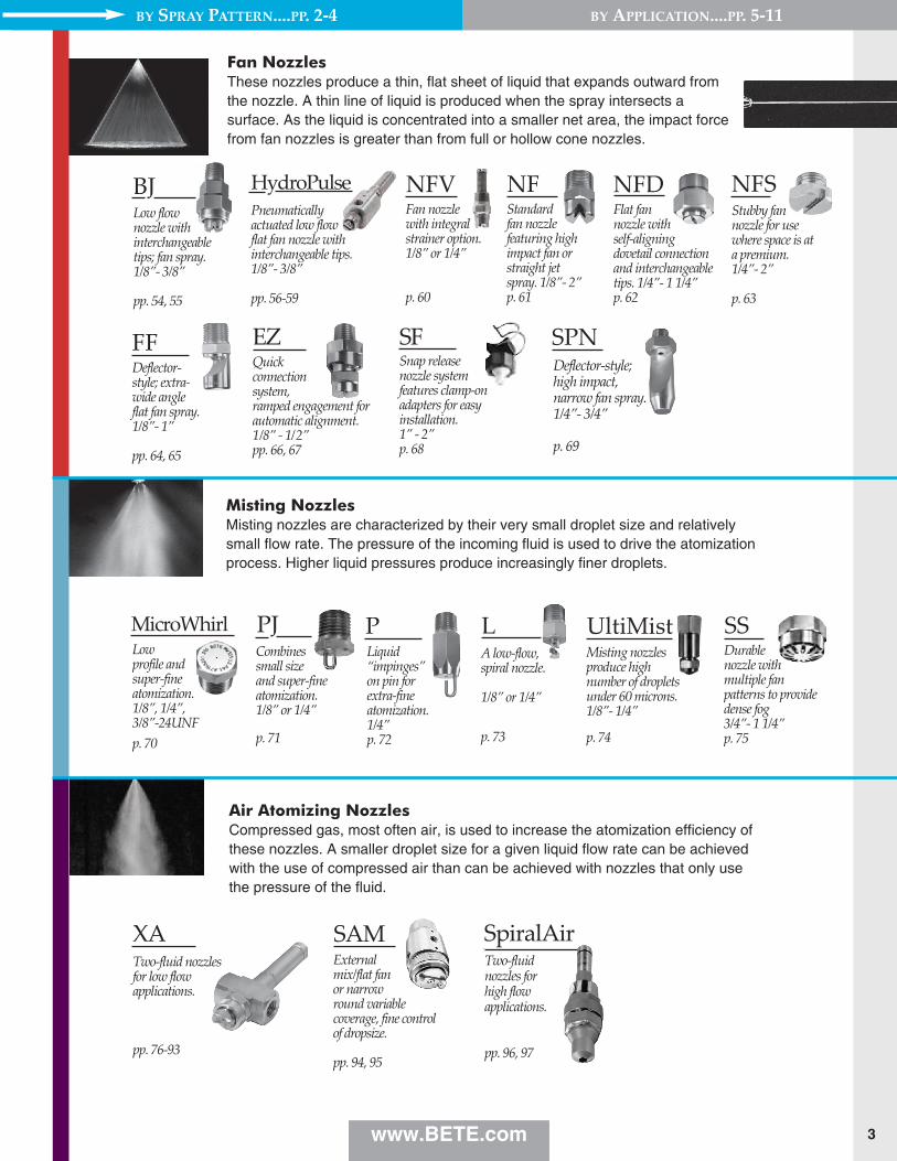
EZ
By SPrAy PATTErN....PP. 2-4
2
3
NFStandardfan nozzlefeaturing highimpact fan orstraight jetspray. 1/8”- 2” p. 61
BJLow flownozzle with interchangeable tips; fan spray.1/8”- 3/8”
pp. 54, 55
FFDeflector-style; extra-wide angle flat fan spray.1/8”- 1”
pp. 64, 65
SPNDeflector-style;high impact,narrow fan spray. 1/4”- 3/4”
p. 69
XATwo-fluid nozzles for low flow applications.
pp. 76-93
Stubby fannozzle for usewhere space is at a premium. 1/4”- 2”
p. 63
NFDFlat fannozzle withself-aligningdovetail connectionand interchangeabletips. 1/4”- 1 1/4” p. 62
NFS
Two-fluidnozzles forhigh flowapplications.
pp. 96, 97
Externalmix/flat fanor narrowround variablecoverage, fine controlof dropsize.
pp. 94, 95
SAM
PLiquid“impinges”on pin forextra-fineatomization.1/4”p. 72
PJCombines small size and super-fineatomization. 1/8” or 1/4”
p. 71
UltiMistMisting nozzlesproduce highnumber of dropletsunder 60 microns. 1/8”- 1/4”
p. 74
MicroWhirl
SpiralAir
SSDurablenozzle withmultiple fanpatterns to providedense fog 3/4”- 1 1/4”p. 75
Low profile and super-fineatomization.1/8”, 1/4”, 3/8”-24UNFp. 70
LA low-flow,spiral nozzle.
1/8” or 1/4”
p. 73
Quickconnection system, ramped engagement forautomatic alignment.1/8” - 1/2” pp. 66, 67
EZ
www.BETE.com
By APPLICATIoN....PP. 5-11
Fan NozzlesThese nozzles produce a thin, flat sheet of liquid that expands outward fromthe nozzle. A thin line of liquid is produced when the spray intersects asurface. As the liquid is concentrated into a smaller net area, the impact forcefrom fan nozzles is greater than from full or hollow cone nozzles.
NFVFan nozzlewith integralstrainer option.1/8” or 1/4”
p. 60
SFSnap release nozzle system features clamp-onadapters for easyinstallation. 1” - 2”p. 68
Misting NozzlesMisting nozzles are characterized by their very small droplet size and relativelysmall flow rate. The pressure of the incoming fluid is used to drive the atomizationprocess. Higher liquid pressures produce increasingly finer droplets.
Air Atomizing NozzlesCompressed gas, most often air, is used to increase the atomization efficiency ofthese nozzles. A smaller droplet size for a given liquid flow rate can be achievedwith the use of compressed air than can be achieved with nozzles that only usethe pressure of the fluid.
By SPrAy PATTErN....PP. 2-4
HydroPulsePneumaticallyactuated low flowflat fan nozzle withinterchangeable tips.1/8”- 3/8”
pp. 56-59

SPRAY DRYING NOZZLES
Tank Washing NozzlesThese specialized products are customized to the task of cleaning the interior surfacesof tanks. The typical 360° spray pattern covers all internal surfaces while specialized270° and 180° patterns focus the cleaning fluid on specific surfaces. Models range frombasic fixed nozzles to advanced fluid-driven tank cleaning machines.
By SPrAy PATTErN....PP. 2-4 By APPLICATIoN....PP. 5-11
Compact design;fits small openings.Unique patternsthat spray inopposing directions.3/8” & 1”p. 102
TW
Unique, clog-resistant designwith vigorous 360°rinsing action forfood-gradeapplications. 1”& 1-1/2”p. 105
HydroClaw
NSpeciallydesigned for fireprotection.Factory Mutual,UL, U.S. CoastGuard, and Lloyd's Registerapproved models.1/2”-1 1/2”p. 106
A tankwashingmanifoldwith 6 largefree passageMaxiPass nozzles. 3/4” - 1” p. 103
CLUMP
Ultra-wide fireprotection nozzle has fullcone spraycoverage close to the nozzle1/2”
p. 107
TF29-180 Twist & DryStainless steel,FDA- compliantnozzles for foodprocessing andspray dryingapplications. 1/4” - 3/4”
pp. 108-111
TDLStainless steel,FDA-compliantnozzles with lowflow rates for foodprocessing and spraydrying applications.1/8”- 3/8”
p. 112
ISMounted inpairs forrectangularcoverage. 1/16”- 1 1/2”
p. 114
LPSelf-aligning,interchangeablefamily of showernozzles.
p. 115
Tank-mixingeductor nozzle.Inherentlyclog resistant.
3/8” - 8”
p. 113
SJSwivel jointsallow customalignment ofnozzles without piping changes.1/4”- 3/4”
p. 118
TurboMix
PSRSmallphysical size, hard-driving high velocity,straight jet9/16” - 24 UNEFp. 116
High-impact air fannozzle, versatilecleaning nozzle.1/4”
p. 117
FINZ AccessoriesStrainers, bushings,adapters, couplings,manifolds, andflanges to completeyour installation.
p. 119
LEMA special tankwashing assemblywith omni-directional spray. 3/4”& 1”
p. 104
Slotted, rotating tankwashing spraynozzle. Availablewith ATEX approvalfor Zone 0.1/8” - 1-1/2”p. 99
HydroWhirl SRotating tankwashing nozzle inPTFE. Ideal forharsh chemicalenvironments.1/2”- 1-1/2”p. 100
HydroWhirl Poseidon
High impact rotarytank cleaning machine.360° and 180° washpatterns. 2 or 4 nozzleconfigurations
p. 101
HydroWhirl Orbitor
Special Purpose Nozzles and AccessoriesApplications with very specific requirements require specialized nozzles.Nozzles for fire control, spray drying, submerged tank mixing, the paperindustry, and air blowoff are some that require application-specific designs.
FIRE PROTECTION NOZZLES
www.BETE.com4

By SPrAy PATTErN....PP. 2-4 By APPLICATIoN....PP. 5-11
5www.BETE.com
...by APPLICATIoNChoosing the correct nozzle for your application fromBETE’s 20,000+ products can be daunting. To help,here is a list of some of the more common uses forspray nozzles. Each application is followed by severalBETE nozzle series which have been used in thisapplication. The series used most often is listed first.
The operating pressures, flow rate, and spray angleranges are typical for each application. The fulloperating range for each series is generally broader.
If you don't see your application, or need advice makinga nozzle selection, please call us at 413-772-0846.
3.5-7 bar2-10 l/min90°-120°
p. 20
TF
1.5-4 bar0.4-7 l/h20°-60°2.4-14 Nm3/hpp. 76-93
XA
1.5-3.5 bar10-40 l/min90°-120°
p. 20
TF
3-5 bar4.0-102 l/min0.6-90 Nm3/h
pp. 62, 63
NF (D,S)
3.5-7 bar2-10 l/min90°-120°
p. 21
TFXP
4-7 bar0.1-0.4 l/min65°-120°
p. 61
NF
1.5-3.5 bar10-40 l/min90°-120°lumpy liquidsp. 21
TFXP
3-5 bar4.0-102 l/min0.3-90 Nm3/h
pp. 64, 65
FF
4-7 bar0.03-0.4 l/min50°-80°
pp. 54, 55
BJ
0.7-3 bar5-40 l/h90°-120°lumpy liquidspp. 26, 27
MaxiPass
3-5 bar4.0-102 l/min0.6-90 Nm3/h
p. 69
SPN
3-5 bar4.0-102 l/min0.6-90 Nm3/h
p. 61
NF3-5 bar4.0-102 l/min0.3-90 Nm3/h
pp. 64, 65
FF2-30 bar3.2-100 l/min0.6-90 Nm3/h
p. 69
SPN
1.5-4 bar0.4-7 l/h20°-60°2.4-14 Nm3/hpp. 76-93
XA4-70 bar0.05-5.34 l/h90°
p. 71
PJ
0.5-1 bar371-2230 l/min90°-120°lumpy liquidspp. 26, 27
MaxiPass0.5-1 bar371-2230 l/min54°-95°SNBSC avail.pp. 50, 51
TH0.5-1 bar371-2230 l/min90°-120°
pp. 34, 35
NC0.5-1 bar371-2230 l/min90°-120°metal nozzlepp. 32, 33
SC
70-200 bar0.04-0.60 l/min20°-70°
p. 70
MicroWhirl
0.7-1 bar20°-70°0.8-7.2 Nm3/h
pp. 90, 91
SAM
0.7-6 bar7-65 Nm3/h
p. 117
FINZ
0.7-6 bar7-65 Nm3/h
p. 117
FINZ
Color Code:Full Cone
Hollow Cone
Fan
Misting
Special Purpose
Air Atomizing
Tank Washing
AbsorptionScrub hydrofluoric acid, ammonia, and other highly soluble gases
AdditivesApply small volumes of a solution onto moving product or into a mixture
AerationAerate waste water treatment, fish ponds,and impoundment ponds
Air ConditioningCooling air at gas turbine inlets
Air and SteamClean or dry productmoving past nozzle;inject gases and odorantsinto process lines; sparging; bubbling
Blowoff NozzlesRemove water or dustfrom strips and conveyors
Air NozzleBlowoff nozzle uses compressed air only

By SPrAy PATTErN....PP. 2-4 By APPLICATIoN....PP. 5-11
6 www.BETE.com
0.5-1 bar75-454 l/min90°-120°lumpy liquidsp. 21
TFXP0.5-1 bar75-454 l/min90°-120°
p. 20
TF - full0.2-1 bar61-341 l/min80°-100°
pp. 50, 51
TH0.7-1.5 bar23-341 l/min90°
pp. 26, 27
MaxiPass
1.5-4 bar11-265 l/h20°0.6-16 Nm3/hpp. 76-93
XA
2-4 bar3.2-93 l/hr20°- 70°0.9-24 Nm3/hpp. 76-93
XA
0.7-1.5 bar45-945 l/min90°-120°
p. 20
TF
3-7 bar1.2-68 l/min20°-60°40-220 Nm3/hpp. 96, 97
SpiralAir
2-5.5 bar0.8-64 l/min50°-120°
pp. 62, 63
NF (D,S)
0.2-1.5 bar23-940 l/min90°-120°lumpy liquidspp. 26, 27
MaxiPass
0.7-4 bar4.77-888 l/min90°-120°lumpy liquidspp. 26, 27
MaxiPass
4-10 bar6-68 l/min90°-120°
p. 20
TF - full
0.5-20 bar9.7-10700 l/min90°-120°lumpy liquidsp. 21
TFXP0.2-5 bar2.8-3400 l/min30°-120°lumpy liquidspp. 26, 27
MaxiPass0.7-15 bar1.9-177 l/min15°-50°
p. 69
SPN
4-7 bar0.05-1.7 l/min90°
p. 71
PJ
5-70 bar0.058-5.34 l/min90°
p. 71
PJ
0.3-1.5 bar2-53 l/min80°-120°
p. 25
WL
0.7-4 bar0.5-94 l/min90°-120°
p. 24
WL
4-10 bar6-68 l/min90°-120°lumpy liquidsp. 21
TFXP
3-7 bar1-4 l/min90°
p. 73
L
4-14 bar1.2-21 l/min90°
p. 73
L4-14 bar1.2-21 l/min90°
p. 72
P1.5-4 bar11-100 l/h20°-60°1.2-19 Nm3/hpp. 76-93
XA
2-5.5 bar0.3-40 l/min25°-80°
pp. 54, 55
BJ
2-4 bar19.3-232l/min180°- 270°very compactp. 102
TW
0.2-3 bar15.3-2230 l/min54°-95°SNBSC avail.pp. 50, 51
TH0.5-10 bar0.8-70.4 l/min90°-110°
p. 41
WTZ
0.7-4 bar11.3-640 l/min90°-120°metal nozzlepp. 32, 33
SC
0.2-10 bar0.05-757 l/min145°
pp. 64, 651
FF
0.2-1.5 bar23-940 l/min90°-120°
pp. 34, 35
NC
0.7-4 bar2.7-588 l/min90°-120°
p. 20
TF0.7-4 bar2.7-588 l/min90°-120°
p. 21
TFXP
3-5 bar4.0-102 l/min120°
p. 61
NF3-5 bar4.0-102 l/min105°-145°
pp. 64, 65
FF2-30 bar3.2-100 l/min35°-50°
p. 69
SPN
0.7-1 bar20°-70°0.8-7.2 Nm3/h
pp. 94, 95
SAM
70-200 bar0.04-0.60 l/min20°-70°
p. 70
MicroWhirl
70-200 bar0.04-0.60 l/min20°-70°
p. 70
MicroWhirl
0.5-4 bar4.39-338 l/min360°
p. 99
HydroWhirl S0.7-4 bar58.3-333 l/min360°
p. 100
HydroWhirl Poseidon
3-10 bar80-600 l/min180°, 360°
p. 101
HydroWhirl orbitor
4-10 bar6-68 l/min90°-120°
p. 45
TF - hollow
0.1-0.7 bar820-13250 l/min60°-120°
p. 39
TC
0.7-6 bar0.44-7.97 l/min90°-120°
p. 25
MPL
0.5-1 bar75-454 l/min90°-120°
p. 45
TF - hollowCooling:PondCool pond water; heat recovery
CoatingApply thin coatings (wet or dry) on productmoving past nozzles
Concrete CuringHumidify concrete tocontrol curing process
Cooling: DelugeProcess cooling for food, chemical, andindustrial processes
Cooling:EvaporativeCool hot (+ 300°F) flue gases prior to entering abaghouse or temperature-sensitive equipment
Cooling:PartsCool hot parts on conveyorsfrom pre-treatment ovens
Car Wash NozzlesHigh pressure wash nozzles used in automatedcar wash units.
Clean in PlaceNozzlesRotating and stationarybottle, drum, and tankwashing nozzles
Clog-resistantNozzlesWide free passage tospray lumpy, viscous liquids with less clogging
1.5-3 bar279-442 l/min360°
p. 105
HydroClaw
7
By SPrAy PATTErN....PP. 2-4 By APPLICATIoN....PP. 5-11
www.BETE.com
0.2-1.5 bar11-13250 l/min90°-120°plastic nozzlepp. 34, 34
NC
2-5.5 bar4.5-43 l/min90°-120°
p. 20
TF
2-5.5 bar4.6-43 l/min90°-120°
p. 20
TF
0.2-1.5 bar4-1930 l/min90°-120°lumpy liquidspp. 26, 27
MaxiPass
2-5.5 bar19.5-43 l/min90°-120°lumpy liquidsp. 21
TFXP
2-5.5 bar20-57 l/min150°wide coveragep. 20
TF150
0.2-1.5 bar7.6-1597 l/min90°-120°metal nozzlepp. 32, 33
SC
3-5.5 bar9-47 l/min90°-120°lumpy liquidspp. 26, 27
MaxiPass
3-5.5 bar9-47 l/min90°-120°lumpy liquidspp. 26, 27
MaxiPass
0.1-0.7 bar820-13250 l/min60°-120°
p. 39
TC
2-5.5 bar20-57 l/min90°-120°lumpy liquidsp. 21
TFXP
0.05-0.7 bar2-435 l/minused in pairslumpy liquidsp. 114
IS
3-5.5 bar1-13 l/min90°very fine dustp. 73
L
2-5.5 bar20-57 l/min170°wide coveragep. 20
TF170
0.3-1.5 bar4-57 l/min90°-120°
p. 24
WL
3-5.5 bar0.25-14.5 l/min90°very fine dustp. 72
P
3-5.5 bar1-14.5 l/min90°transfer pointp. 73
L
0.7-3 bar0.5-15.1 l/min60°-120°
p. 24
WL0.7-3 bar1.8-15 l/min35°-50°
p. 69
SPN0.2-1.5 bar0.05-14 l/min145°
pp. 64, 65
FF
0.2-35 bar0.05-162 l/min0°-145°
pp. 66, 67
EZ FF, NF, SPN0.2-35 bar0.13-206 l/min30°-120°
p. 30
EZ WL, TF
0.7-3 bar0.5-26.5 l/min50°-120°
pp. 62, 63
NF (D,S)
3-8 bar10-265 l/min90°-120°lumpy liquidsp. 21
TFXP3-8 bar10-265 l/min90°-120°
p. 20
TF - full3-8 bar21-246 l/min90°-120°lumpy liquidspp. 26, 27
MaxiPass
3-5 bar0.6-90 Nm3/h
p. 61
NF3-5 bar0.3-90 Nm3/h
pp. 64, 65
FF3-5 bar0.6-90 Nm3/h
p. 69
SPN0.7-6 bar7-65 Nm3/h
p. 117
FINZ
3-70 bar4-5250 l/min30°-90°
p. 61
NF3-4 bar7.9-91.2 l/min35°-50°
p. 69
SPN
70-200 bar0.09-0.28 l/min90°
p. 70
MicroWhirl
Color Code:Full Cone
Hollow Cone
Fan
Misting
Special Purpose
Air Atomizing
Tank Washing
0.2-35 bar0.13-206 l/min30°-120°
p. 46
EZ WL, TF, WT
4-10 bar6-68 l/min90°-120°
p. 45
TF - hollow
3-7 bar1.2-68 l/min20°-60°40-220 Nm3/hpp. 96, 97
SpiralAir
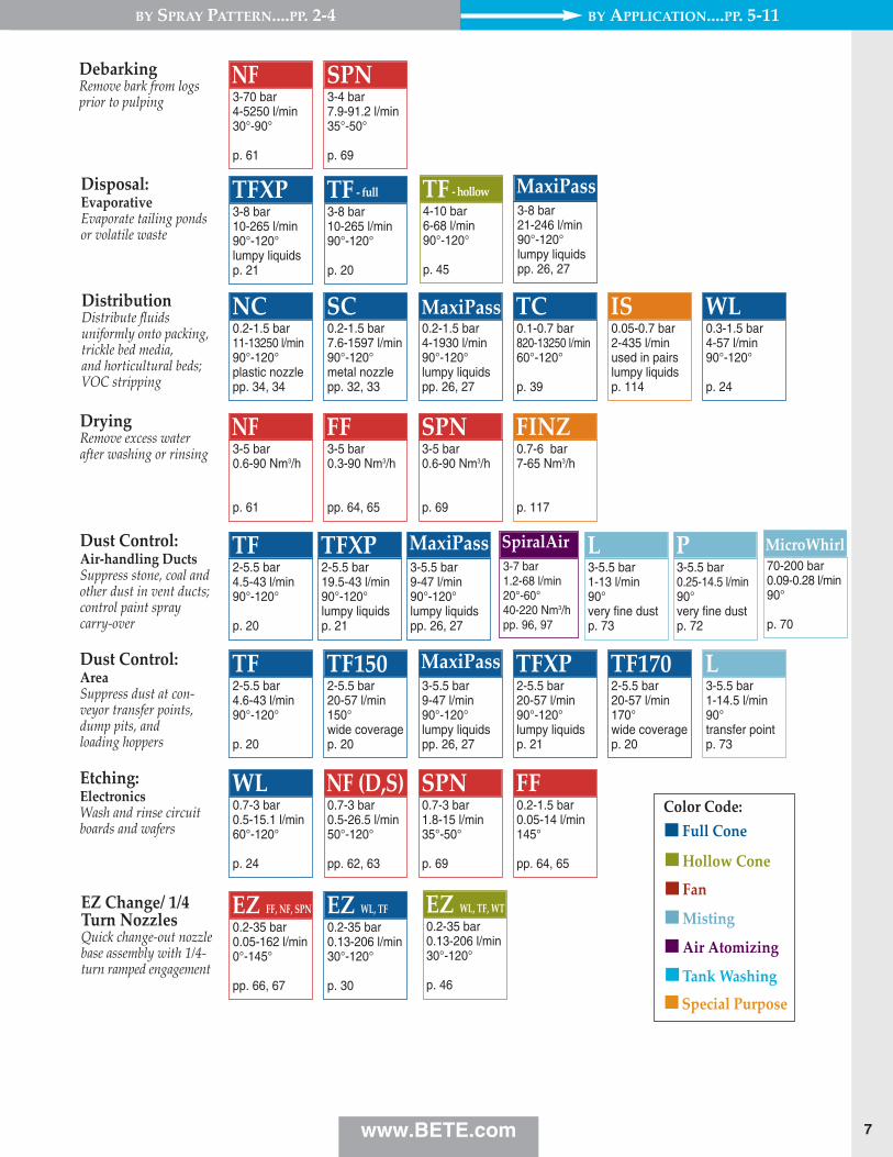
DistributionDistribute fluids uniformly onto packing,trickle bed media, and horticultural beds;VOC stripping
Dust Control: Air-handling DuctsSuppress stone, coal andother dust in vent ducts;control paint spraycarry-over
Dust Control: AreaSuppress dust at con-veyor transfer points,dump pits, and loading hoppers
Etching:ElectronicsWash and rinse circuitboards and wafers
EZ Change/ 1/4Turn NozzlesQuick change-out nozzlebase assembly with 1/4-turn ramped engagement
Disposal: EvaporativeEvaporate tailing pondsor volatile waste
DryingRemove excess waterafter washing or rinsing
DebarkingRemove bark from logsprior to pulping

By SPrAy PATTErN....PP. 2-4 By APPLICATIoN....PP. 5-11
8 www.BETE.com
0.2-1 bar6-435 l/min90°-120°lumpy liquidspp. 26, 27
MaxiPass
0.7-5 bar0.1-18.3 l/min145°
pp. 64, 65
FF
0.4-1.5 bar11-53 l/min90°-120°
p. 24
WL
2-4 bar1.5-113 l/h20°-40°1-27 Nm3/hpp. 76-93
XA
0.7-7 bar16-227 l/h20°-120°
pp. 76-93
XA
5-15 bar0.06-2.5 l/min90°
p. 71
PJ
0.4-1 bar227-2460 l/min90°-120°recycle slurryp. 23
STXP0.4-1 bar227-2460 l/min90°-120°resist erosionp. 22
ST0.2-1.5 bar200-1930 l/min90°-120°recycle slurrypp. 26, 27
MaxiPass
0.2-5 bar2.8-3400 l/min30°-120°
pp. 26, 27
MaxiPass
0.2-1.5 bar170-2300 l/min90°-120°SNBSC avail.pp. 50, 51
TH0.2-1.5 bar42-1597 l/min90°-120°plastic nozzlepp. 34, 35
NC0.2-1.5 bar91-1300 l/min90°-120°metal nozzlepp. 32, 33
SC
4-14 bar0.5-2.4 l/min90°
p. 71
PJ5.5-14 bar7-23 l/min120°hollow conep. 20
TF
0.5-20 bar9.7-10700 l/min90°- 120°
p. 21
TFXP
3-70 bar5.5-76 l/min90°-120°
p. 20
TF - full
5.5-14 bar1.5-13 l/min90°
p. 73
L4-7 bar1.1-57 l/min20°-60°59-225 Nm3/hpp. 96, 97
SpiralAir
4-10 bar200-1300 l/min90°-120°FM approvedp. 106
N
4-10 bar200-1140 l/min90°-120°
p. 20
TF
4-10 bar35-246 l/min180°wide coveragep. 107
TF29-180
4-10 bar200-1140 l/min150°wide coveragep. 20
TF150
3-7 bar1-72 l/min20°-40°37-185 Nm3/hpp. 96, 97
SpiralAir
4-12 bar200-1140 l/min170°horiz. sprayp. 20
TF170
3-14 bar1-8.3 l/min80°-120°
p. 28
CW
4-8 bar64-570 l/min145°wall wettingpp. 64, 65
FF4-8 bar76-738 l/min90°-120°
pp. 62, 63
NF (D,S)
0.2-1 bar6.3-320 l/min90°-120°
pp. 32, 33
SC
0.7-4 bar1.1-110 l/h20°-40°
pp. 76-93
XA40-150 bar5.3-84 l/hr50°- 110°
p. 74
UltiMist70-200 bar0.04-0.60 l/min20°-70°
p. 70
MicroWhirl
4-10 bar200-1140 l/min90°-120°lumpy liquidsp. 21
TFXP4-10 bar200-1300 l/min90°-120°FM approvedp. 106
N4-8 bar178-674 l/min90°-120°lumpy liquidspp. 26, 27
MaxiPass4-10 bar200-1140 l/min150°wide coveragep. 20
TF150
70-200 bar0.04-0.60 l/min20°-70°
p. 70
MicroWhirl
0.2-3 bar15.3-2230 l/min90°-120°SNBSC avail.pp. 50, 51
TH
4-10 bar6-68 l/min90°-120°
p. 45
TF - hollow
4-10 bar200-1140 l/min90°-120°lumpy liquidsp. 21
TFXP
4-10 bar200-1140 l/min90°-120°lumpy liquidsp. 21
TFXPFoam ControlControl build-up offoam in aeration andsettling basins; mixingvessels and below weirs;and spillways
HumidificationHumidify air in ducts,drying kilns, curingrooms, greenhouses,and other open areas;area misting
Large FreePassage NozzleClog resistant; allowlumpy viscous liquids topass easily
Fog NozzlesFine atomization misting;movie special effects
Food ProcessingApplying flavorants or colorants
Gas ScrubbingSpray reagent into gas
Fire Protection: SpecialProtect coal conveyors;fueling and vulcanizingcabinets; warehousesand munitions storage
Fire Protection: Water WallProtect personnel, evacuation muster areas,equipment, and structuresfrom heat radiation
Fire Protection:DelugeProtect offshore platforms,storage tanks, hazardousloading areas, and equipment bays

9
By SPrAy PATTErN....PP. 2-4 By APPLICATIoN....PP. 5-11
www.BETE.com
15-150 bar1.8-17 l/hr60°- 110°
p. 74
UltiMist
0.7-7 bar40-1000 l/min
p. 113
TurboMix
3-7 bar0-16 l/h60°-120°
pp. 76-93
XA
3-7 bar3.4-320 l/h60°-120°
pp. 76-93
XA
7-150 bar0.14-5 l/min90°
p. 71
PJ
7-140 bar0.1-0.2 l/min90°
p. 71
PJ
3-7 bar0-330 l/h60°-120°
pp. 76-93
XA7-150 bar0.1-50 l/min90°
p. 71
PJ3-30 bar5.5-75 l/min90°- 120°
p. 20
TF - full
1-3 bar15.8-114 l/min90°
pp. 34, 35
NC1.5-4 bar6.4-60 l/min90°
pp. 26, 27
MaxiPass1.5-5.5 bar0.7-106 l/min90°-120°
p. 24
WL
0.2-1.5 bar11-13250 l/min120° plastic nozzlepp. 34, 35
NC0.2-1.5 bar4-1930 l/min90°- 120°lumpy liquidspp. 26, 27
MaxiPass0.3-1.5 bar4-57 l/min90°-120°
p. 24
WL0.2-1.5 bar7.6-1597 l/min90°-120°metal nozzlepp. 32, 33
SC0.1-0.7 bar820-13250 l/min60°-120°metal nozzlep. 39
TC0.05-0.7 bar2-435 l/minused in pairslumpy liquidsp. 114
IS
4-35 bar1.9-167 l/min0°-60°
p. 115
LP
0.4-1 bar227-2460 l/min90°-120°RBSC availp. 23
STXP0.4-1 bar227-2460 l/min90°-120°RBSC availp. 22
ST0.2-1.5 bar200-1930 l/min90°-120°recycle slurrypp. 26, 27
MaxiPass0.2-1.5 bar170-2300 l/min90°-120°SNBSC avail.pp. 50, 51
TH0.2-1.5 bar42-1597 l/min90°-120°plastic nozzlepp. 34, 35
NC0.2-1.5 bar91-1300 l/min90°-120°metal nozzlepp. 32, 33
SC
70-200 bar0.04-0.60 l/min20°-70°
p. 70
MicroWhirl
70-200 bar0.04-0.60 l/min20°-70°
p. 70
MicroWhirl
70-200 bar0.09-0.28 l/min90°
p. 70
MicroWhirl3-7 bar1.2-68 l/min20°-60°40-220 Nm3/hpp. 92, 93
SpiralAir
1.5-4 bar0.4-7 l/h20°-60°3-40 Nm3/hpp. 76-93
XA4-7 bar0.1-0.4 l/min65°- 120°
pp. 62,63
NF (D,S)4-7 bar0.03-0.4 l/min50°- 80°
pp. 54, 55
BJ Color Code:Full Cone
Hollow Cone
Fan
Misting
Special Purpose
Air Atomizing
Tank Washing
4-10 bar6-68 l/min90°-120°
p. 45
TF - hollowMistingMoisten paper; mist produce; compost pilesof crushed products
Mixing EductorsKeep solids suspendedby eduction
MoisteningWetting, humidifyingproducts on conveyor
odor ControlSpray odor neutralizing agents
PackingDistribute scrubbingliquor in scrubbers orwater in humidifiers
Pollution ControlDistribute slurry inopen towers
Mist EliminatorWashClean mist eliminatorsin packed or open tower scrubbers
LubricationLubricate dies andmoulds; roll bite in strip mills

By SPrAy PATTErN....PP. 2-4 By APPLICATIoN....PP. 5-11
10 www.BETE.com
3.5-7 bar5.3-57 l/min20°-60°45-225 Nm3/hpp. 96, 97
SpiralAir
15-350 bar35.3-5970 l/h50°- 80°
pp. 108-111
Twist & Dry
3-4 bar2.6-167 l/h20°-40°1.8-27 Nm3/hpp. 76-93
XA
15-350 bar11.3-469 l/h70°-75°
p. 112
TDL
4-10 bar0.45-57 l/min80°-130°
pp. 40, 41
WT
4-35 bar1.9-167 l/min30°- 60°
p. 115
LP
1.7-7 bar8.3-74 l/min145°wide coveragepp. 64, 65
FF1.7-7 bar8.3-74 l/min15°-50°high impactp. 69
SPN1.7-7 bar85-763 l/min50°-90°
p. 61
NF
5.5-14 bar1.5-6.8 l/min90°
p. 73
L3-8 bar5.5-84.1 l/min90°-120°
p. 20
TF - full
2-4 bar1.5-113 l/h20°-40°1-27 Nm3/hpp. 76-93
XA4-14 bar0.05-2.4 l/min90°
p. 71
PJ5.5-14 bar1.5-6.8 l/min90°
p. 73
L4-7 bar1.1-57 l/min59-150 Nm3/h20°-60°pp. 96, 97
SpiralAir
2-7 bar2-80 l/min45-139 Nm3/h20°-90°pp. 96, 97
SpiralAir
0.7-3 bar0.5-26.5 l/min60°-120°
pp. 62, 63
NF (D,S)
2-7 bar2-80 l/min25-135 Nm3/h20°-90°pp. 96, 97
SpiralAir
0.4-1 bar227-2460 l/min90°-120°recycle slurryp. 23
STXP0.4-1 bar227-2460 l/min90°-120°resist erosionp. 22
ST0.2-1.5 bar200-1930 l/min90°-120°recycle slurrypp. 26, 27
MaxiPass0.2-1.5 bar170-2300 l/min90°-120°SNBSC avail.pp. 50, 51
TH0.2-1.5 bar42-1597 l/min90°-120°plastic nozzlepp. 34, 35
NC0.2-1.5 bar91-1300 l/min90°-120°metal nozzlepp. 32, 33
SC
1.5-4 bar0-196 l/min105°-145°
pp. 64, 65
FF3-7 bar4-36 l/min20°-60°
p. 61
NF
70-200 bar0.04-0.60 l/min20°-70°
p. 70
MicroWhirl
4-10 bar0.45-57 l/min80°-130°
pp. 42, 43
WTX
15-350 bar11.3-469 l/h70°-75°
pp. 110, 111
TD-K
3-4 bar2.6-167 l/h20°-40°1.8-27 Nm3/hpp. 76-93
XA4-70 bar0.03-5.3 l/min90°
p. 71
PJ4-10 bar6-68 l/min90°-120°
p. 45
TF - hollow70-200 bar0.04-0.60 l/min20°-70°
p. 70
MicroWhirl
3-8 bar5.5-84.1 l/min90°-120°
p. 20
TF
Scrubbing: DryInject lime slurry; injectfood and chemical prod-uct into spray dryer
Self CleaningNozzles/ ShowersClean webs in papermills, wash or rinse steelstrip or conveyor belts
Street Flushing &CleaningHigh impact wash down,clear loose debris fromstreets; walkways
Spray DryingProcessing of milk, otherfoods and chemical products
Scrubbing:Direct ContactSpray water or reagentslurry into open tower;flue gas desulphurization
Scrubbing:ConditioningInject ammonia or waterupstream of electrostaticprecipitators; inject odorcontrol additives
Pulp BleachingWall wash bleaching tanks
QuenchEvaporatively quenchhot gases
roll CoolingCool rolls in steel strip mills

11
By SPrAy PATTErN....PP. 2-4 By APPLICATIoN....PP. 5-11
www.BETE.com
0.7-5.5 bar11-273 l/min210°very compactp. 102
TW0.7-3 bar29-224 l/min360°lumpy liquidsp. 103
CLUMP0.7-5.5 bar30-530 l/min360°even rinsingp. 104
LEM
1-5.5 bar2.3-56 l/min35°-95°
p. 68
SF0.7-4 bar1.4-98 l/min90°-120°
p. 24
WL0.7-3 bar14-144 l/min60°-120°plastic nozzlepp. 34, 35
NC0.7-3 bar11-167 l/min60°-120°metal nozzlepp. 32, 33
SC0.7-5.5 bar7.6-106 l/min15°-50°high impactp. 69
SPN1.5-5.5 bar0.7-106 l/min65°-120°
pp. 62, 63
NF (D,S)
1.5-4 bar6.4-60 l/min60°-120°lumpy liquidspp. 26, 27
MaxiPass1-3 bar15.8-114 l/min60°-120°plastic nozzlepp. 34, 35
NC1.5-5.5 bar0.7-106 l/min80°-120°
p. 24
WL1-3 bar17-121 l/min60°-120°metal nozzlepp. 32, 33
SC
0.5-3 bar10-159 l/min90°-120°lumpy liquidsp. 21
TFXP0.2-3 bar2.6-144 l/min60°-120°lumpy liquidspp. 26, 27
MaxiPass0.2-4 bar1.5-110 l/min145°wide coveragepp. 64, 65
FF3-4 bar1-11 l/min90°transfer pointp. 73
L0.7-5.5 bar7.6-106 l/min15°-50°high impactp. 69
SPN0.4-4 bar5.3-1700 l/min65°-120°
pp. 62, 63
NF (D,S)
0.5-7 bar23.1-4660 l/min30°
p. 37
NCK
0.5-4 bar4.39-338 l/min360°
p. 99
HydroWhirl S0.7-4 bar58.3-333 l/min360°
p. 100
HydroWhirl Poseidon
3-10 bar80-600 l/min180°, 360°
p. 101
HydroWhirl orbitor
0.5-7 bar23.1-4660 l/min30°
p. 49
NCJ
Washing: TankRinsing and solventcleaning of tanks, drums,and process equipment
Washing:PartsHigh impact parts washingand surface preparation
Washing:IntermittentPeriodic wash down ofmist eliminator, filterpads, sieve screens, anddistribution plates
Washing:ConveyorWash coal, sand, gravel,and crushed rock; pre-wetto reduce dust at hoppersand transfer points
VenturiScrubbingKeep solids suspendedby injection
1.5-3 bar279-442 l/min360°
p. 105
HydroClaw
Color Code:Full Cone
Hollow Cone
Fan
Misting
Special Purpose
Air Atomizing
Tank Washing

BETE manufactures nozzles in hundredsof different materials and combinationsof materials. The chart on this pageshows the 40 materials most oftenspecified. If you don’t know whichmaterial is best for your application,BETE Applications Engineering can helpyou with your selection. Some factorsthat influence the nozzle materialselection process are:Temperature. Melting orsoftening of materialestablishes maximumtemperature limits.However, thesetemperature limits mustbe reduced whencorrosion, oxidation, orchemical attack are alsopresent. See column inblue for generaltemperature limits forvarious materials.Corrosion. Plastics offersuperior corrosionresistance at relatively lowcost, but can only be usedin low-temperatureapplications. In general,metals can be ranked inthe following order ofcorrosion resistance (fromlowest to highest): castiron, brass, stainless steels,nickel-based alloys,refractory metals andprecious metals. Ceramicshave excellent corrosionresistance except in veryhigh pH environments.Chemical attack. Thereare few general guidelinesto this complex subject,but the material used forpiping may provide auseful indicator of asuitable nozzle material. If the environment of your
application is known to containsubstances which may attack thespray nozzle, contact BETEApplications Engineering for advice.Abrasion. Hardened stainless steel,Cobalt Alloy 6, tungsten carbide,and ceramics are commonly used inapplications where abrasive fluidsare sprayed.
Cost. There are exceptions, but materials can generally be rankedin the following order in terms ofcost (from lowest to highest):brass, cast iron, plastics, stainlesssteels, cobalt-base alloys, nickel-base alloys, ceramics, refractorymetals and precious metals.
MATErIALS
The following are registered trademarks: Teflon®,Viton® (E.I. DuPont de Nemours & Co.); Hastelloy®(Haynes International, Inc.); Incoloy®, Monel® (TheInternational Nickel Company, Inc.); Inconel® (IncoNickel Sales, Inc.); Kynar® (Penwalt Corporation);REFRAX® (Carborundum Company); and Stellite®(Stoody Deloro Stellite, Inc.); M&M (Mars, Inc.) TheBETE logo and MaxiPass are registered trademarks ofBETE Fog Nozzle, Inc. ©BETE Fog Nozzle, Inc.
BETE Temp. Material Material (DIN) Rating Trade Description No. (MN) Description (° C) Name*
Brass 4 Messing 230° Naval Brass 64 400° Bronze Bronze 400° L.C. Steel 72 C-Stahl 210° 303 5 1.4305 430° 304 6 1.4301 430° 304L 1.4306 430° 316 7 1.4401 430° Tungsten Carbide 7HAlumina 26316L 20 1.4404 430° 317 21 1.4440 430° 317L 22 1.4438 430° 416 24 1.4005 430°
904L 74 1.4539 430° Alloy 20 70 2.4660 490° Carpenter® 20 Nickel Alloy M30C 37 2.4360/2.4366 540° Monel® Nickel Alloy 600 35 2.4816 1100° Inconel® 600 Nickel Alloy 625 3B 2.4856 1100° Inconel® 625 Nickel Alloy 800 33 1.4876 1010° Incoloy® 800 Nickel Alloy 825 34 2.4858 1010° Incoloy® 825 Nickel Alloy B 31 2.4800/2.4810 760° Hastelloy® B w/2.5 Max. CoNickel Alloy G 32 2.4619 1100° Hastelloy® G Nickel Alloy G30 49 2.4603 1100° Hastelloy® G30 Nickel Alloy C276 81 2.4819 1100° Hastelloy® C276 Nickel Alloy C22 2A 2.4602 1100° Hastelloy® C22 Nickel 38 Nickel 350° Titanium 11 Titan 540° Tantalum 40 Tantal 1500° Zirconium 61 Zirkonium 540° Cobalt Alloy 6 9 1050° Stellite® 6 SNBSC ceramic 62 1660° Refrax® RBSC ceramic 59 1380° PTFE 3 PTFE 150° Teflon® PVDF 36 PVDF 120° Kynar® PVC 1 PVC 60° CPVC 16 CPVC 100° Polypropylene 2 Polypropylen 70° UHMW 17 80° Polyurethane 69 80° ABS 15 70° * BETE does not represent that it manufactures its products with materials sold under any of these brandnames. Customers sometimes ask for BETE products without using a USA standard specification for the materialthey require. When materials are described incompletely, with DIN specifications or with a commonly used brandname, BETE will usually supply materials according to the USA specifications listed above. Specifications for formsother than cast or bar may differ from the above.
12 www.BETE.com

Since 1950 BETE has put nozzles into deep sea,deep space, and everywhere in between.
John Bete startedthe company in1950 in a basementmachine shop.
Innovative BETEnozzles havemade the com pany a world-wide leader in the pollution controlindustry.
The first showerin space wastaken by a U.S.astronaut using a special BETE nozzle.
BETE nozzles provide life-saving fire protection on offshore oil rigs, clean com-pact disk masters betweenplatings, cool off the hogsdown on the farm, reduce SO2
emissions at coal-fired gener-ating stations, and even sprayrelish into huge mixing vatsat food processing plants.
Virtually every business usesnozzles—in equipment, manu-facturing or fire protection.Their spray droplets can neu-tralize micron-size pollutants,extinguish fires, cool hot gases,coat delicate electroniccomponents, andmuch more. BETE is a pioneerin all areas of nozzlemanufacturing. Thecompany was formed to pro-duce John Bete’s unique spiral
(corkscrew) nozzlewhich can deliver afine, high velocityspray at the lowestpossible pressure. Later, BETEdeveloped theindustry’s leading clog-resis-tant design: the MaxiPass®
full cone whirl nozzle, whichboasts the maximum free passage possible. More recently, BETEdeveloped the SpiralAir®
series of air atomizing noz-zles which use compressedair or steam to convert largevolumes of liquid into a finelyatomized fog. In each case, these innova-tions have provided solutionsto performance problemsencountered with traditionalnozzle designs.
In fact, if there’s one hallmarkto The BETE Difference it’sthe ability to respond quicklyand effectively to any kind ofspraying challenge—whethersimple or complex—any-where in the world.
Virtually any material thatcan be machined, cast ormolded can be used to make anozzle. The selection dependson the fluid being sprayed andoperating conditions such astemperature, abrasiveness,and corrosiveness.
Nozzles may be a rather small component ofmajor systems. But they are absolutely critical to performance and efficiency.
www.BETE.com 13

BETE is the only nozzle manufacturer with acomplete in-house investment casting foundry.
It takes eight minutes to heat27kg of stainlesssteel to the1500°C requiredfor casting.
BETE pioneeredthe use of manynozzle materialsincluding PTFEand titanium.
Platinum is themost expensivematerial the com-pany has everused; every scrapwas saved.
Traditional NewEngland craft-manship in astate-of-the-artmanufacturingfacility.
BETE has always takenadvantage of the latest devel-opments in materials technol-ogy to create the most efficient nozzles possible. Inthe late 1960s, the companybegan experimenting withnozzles made from theceramic Silicon NitrideBonded Silicon Carbide(SNBSC) because of its excel-lent corrosion and abrasionresistance. Later, BETE madethe first nozzle out of theeven stronger ReactionBonded Silicon Carbide(RBSC); making the production of ceramic spiralnozzles practical. In the 1970s BETE pio-neered the use of CobaltAlloy 6, a cobalt-based alloy
with excellent corrosion andabrasion re sistance, and hasled the way in the use of engi-neering plastics, particularlyPTFE, in nozzle manufacture.
In 1977 BETE made a significant new productioncommitment by setting up anin-house casting foundry.This established total controlof quality and scheduling fororders requiring cast alloyssuch as Stainless Steel, CobaltAlloy 6, and Nickel Alloy.
In the late ‘80s and early‘90s BETE became one of thefirst foundries in the world tocast Nickel AlloyC-22®, a newchromium nickel-based alloy. When evaluating variousmaterials, it’s important to con-sider the impact of nozzle lifeon plant efficiency. BETE canhelp you select the material formaximum effectiveness and op -erating life in your application.
BETE usesthree basic manufacturingprocesses: injectionmolding, machin-ing from bar stock,and investmentcasting. Injection
molding is used for largequantities of nozzles madefrom plastics such as PVC, ABSand PVDF. Bar stockmachin-ing is often used for metalalloy and plastic nozzles whichhave relatively simple shapesor are made in small quanti-ties. Investment casting offers aprecise and economical way toproduce complex shapes inalloys that are difficult orexpensive to machine.
14 www.BETE.com
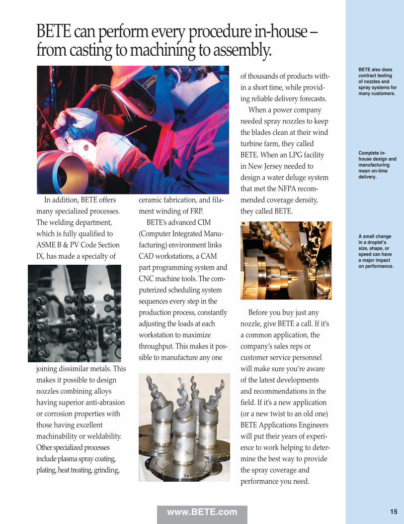
BETE can perform every procedure in-house –from casting to machining to assembly.
BETE also doescontract testingof nozzles andspray systems formany customers.
Complete in-house design andmanufacturingmean on-timedelivery.
A small change in a droplet’ssize, shape, orspeed can have a major impact on perform ance.
In addition, BETE offersmany specialized processes.The welding department,which is fully qualified toASME B & PV Code SectionIX, has made a specialty of
joining dissimilar metals. Thismakes it possible to designnozzles combining alloyshaving superior anti-abrasionor corrosion properties withthose having excellentmachinability or weldability.Other specialized processesinclude plasma spray coating,plating, heat treating, grinding,
ceramic fabrication, and fila-ment winding of FRP. BETE’s advanced CIM(Computer Integrated Manu-facturing) environment linksCAD workstations, a CAMpart programming system andCNC machine tools. The com-puterized scheduling systemsequences every step in theproduction process, constantlyadjusting the loads at eachworkstation to maximizethroughput. This makes it pos-sible to manufacture any one
of thousands of products with-in a short time, while provid-ing reliable delivery forecasts. When a power companyneeded spray nozzles to keepthe blades clean at their windturbine farm, they calledBETE. When an LPG facilityin New Jersey needed todesign a water deluge systemthat met the NFPA recom-mended coverage density,they called BETE.
Before you buy just anynozzle, give BETE a call. If it’sa common application, thecompany’s sales reps or customer service personnelwill make sure you’re awareof the latest developmentsand recommendations in thefield. If it’s a new application(or a new twist to an old one)BETE Applications Engineerswill put their years of experi-ence to work helping to deter-mine the best way to providethe spray coverage and performance you need.
www.BETE.com 15
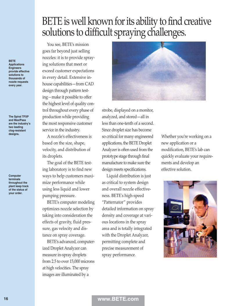
BETE is well known for its ability to find creativesolutions to difficult spraying challenges.
BETEApplicationsEngineersprovide effectivesolutions to thousands ofnozzle requestsevery year.
The Spiral TFXPand MaxiPassare the industry’s two leading clog-resistantdesigns.
Computer terminalsthroughout theplant keep trackof the status ofyour order.
You see, BETE’s missiongoes far beyond just sellingnozzles: it is to provide spray-ing solutions that meet orexceed customer expectationsin every detail. Extensive in-house capabilities—from CADdesign through pattern test-ing—make it possible to offerthe highest level of quality con-trol throughout every phase ofproduction while providingthe most responsive customerservice in the industry. A nozzle’s effectiveness isbased on the size, shape,velocity, and distribution ofits droplets. The goal of the BETE test-ing laboratory is to find newways to help customers maxi-mize performance whileusing less liquid and lowerpumping pressure. BETE’s computer modelingoptimizes nozzle selection bytaking into consideration theeffects of gravity, fluid pres-sure, gas velocity and dis-tance on spray coverage. BETE’s advanced, computer-ized Droplet Analyzer canmeasure in-spray dropletsfrom 2.5 to over 15,000 micronsat high velocities. The sprayimages are illuminated by a
strobe, displayed on a monitor,analyzed, and stored—all inless than one-tenth of a second.Since droplet size has becomeso critical for many engineeredapplications, the BETE DropletAnalyzer is often used from theprototype stage through finalmanufacture to make sure thedesign meets specifications. Liquid distribution is justas critical to system designand overall nozzle effective-ness. BETE's high-speed“Patternator” providesdetailed information on spraydensity and coverage at vari-ous locations in the sprayarea and is totally integratedwith the Droplet Analyzer,permitting complete and precise measurement of spray performance.
Whether you’re working on anew application or a modification, BETE’s lab canquickly evaluate your require-ments and develop an effective solution.
www.BETE.com16

The most important function of any nozzle is making your process work correctly. BETE employs multiple methods to analyze nozzle spray characteristics and how they affect your process.
PHYSICAL SPRAY LABORATORY TESTING
There is no better way to determine nozzle performancethan to spray it and measure how it performs. BETE’slaboratory is capable of fully characterizing single andtwo-fluid sprays, including flow rate, spray angle, spraycoverage, pattern distribution, and droplet size. Dropletsize measurement is performed using a video analyzer,providing robust measurement of spherical and non-spherical droplets alike while allowing a straightforwardunderstanding of this complex topic.
BETE’s lab capabilities extend beyond just the nozzle tohow the nozzle functions in your process. Gas velocity effects on the spray, elevatedtemperature tests, lifetime determination tests, and material erosions tests are just a few of theways that BETE Labs is putting its expertise to work for you.
17
CALL 413-772-0846
Call for the nam
e of your nearest BETE representative.
www.BETE.com
The BETE DropletAnalyzer is capable ofcharacterizing non-spherical droplets likethose seen in this actual image.
Actual droplet imagescaptured using the BETEModel 700 Spray Analysis System.
Spray Analysis
COMPUTATIONAL FLUID DYNAMICS
When duplicating an industrial process for physicaltesting is not feasible, computational modeling is aneffective alternative. Computational fluid dynamics (CFD)software, coupled with actual spray performance datacaptured in our laboratory, can model a wide variety ofsystems to predict distribution, velocity, temperature, flowpaths, droplet evaporation, wall hit, and almost anyphysical quantity. CFD lets you know that your process isgoing to work before you build it.
SPRAY ANALYSIS

TO ORDER
:specify pipe size, connection type, nozzle
number, spray angle, and material.
18
BETE takes its ability to provide robust spray nozzles one step further to constructspray assembly fabrications that you can install for immediate use.
Refineries and chemical plants have counted on BETE for decades to supplycomplete fabricated assemblies, custom designed from the nozzle up. Starting withthe process conditions, we recommend the most appropriate nozzle and thenincorporate it into an assembly that meets all mechanical design criteria.
BETE works to your requirements, from the most simple to the most complex.Incorporation of client specifications is routine for us as is design, fabrication, andinspection to Code requirements. All design and fabrication work is performed at thesame facility, ensuring close coordination through all phases of the process toensure all mechanical and performance requirements are met.
Spray LancesInjectors Quills Spools Fabrications
SPRAY LANCES
Mechanical Inspections• RT – Radiographic• UT – Ultrasonic• PT – Visible Dye Penetrant• Hydrostatic • Hardness• PMI – Positive Material Identification
Drop-in solutions
Whether you call them lances, quills, or injectors, BETE is your source.
Why endure the time and hassle to source pipe, flanges, nozzles, and fittings separately andthen coordinate fabrication and testing of the assembly when you can have BETE do it all foryou in an ISO 9001-controlled shop environment.
Fabrications are BETE’s specialty, from complex Code compliant fabrications to simple pipeand flange assemblies. By using BETE as a single source supplier, you can concentrate onyour larger process details, knowing that our experience is working for you. Steam-jacketed fabrication with three
spray nozzles installed through thejacket.
LANCES
www.BETE.com
Design Requirements• ASME B31.3 and B31.1 NBEP• Welding qualification to ASME
B&PVC, Section IX• Canadian Registration (CRN)• NACE compliance
Performance Inspections• Flow
• Spray Angle
• Droplet Size
• Special Customer Requirements
Visit www.spraylances.com for more
information.

19
CALL 413-772-0846
Call for the nam
e of your nearest BETE representative.
www.BETE.com
Complete spray solutions
Just as BETE can provide the lance on which thespray nozzle is installed, BETE can also providethe piping section into which the lance is installed.There are many benefits to single-sourcing allcomponents related to the spray nozzle.
When all the work is done by one facility, there areno miscommunications between contractors aboutsize, orientation, or location of the spray ports. Thenozzles can be trial fit into the spool piece as partof the manufacturing process before leaving thefactory. This translates to no last minute on-sitesurprises.
BETE provides everything you need from theconcept design stage to on-site delivery, rightdown to the gaskets, studs, and nuts.
Maintenance without downtime
Retractable lances allow you to remove a nozzle for inspection or service without taking your process offline. A retractablelance allows you to withdraw your nozzle, isolate it from the process, and then remove it completely for servicing all whilemaintaining the integrity of the process boundary. Once the nozzle is serviced or inspected, simply reattach it to the system,open the isolation valve, and insert it back into the process.
For smaller pipe sizes, retractable lances can be inserted and withdrawn manually. For larger sizes, or any size whereautomation or ease of use is required, BETE offers a robust retraction mechanism that effortlessly moves the lance. A simplecordless drill is all that is required to power the unit, making this design a favorite with maintenance crews. The mechanism isflexible in its configuration, allowing alternate electric, pneumatic, or hydraulic power sources to drive the unit.
RETRACTABLE LANCESSPRAY LA
NCES
SPOOL SECTIONS
Complete retractable system including lance, isolation valve, and retraction mechanism

TF
Approx. (mm) Wt. (g)
Male Available LITERS PER MINUTE @ BAR Free Dim. (mm) for 60° 90°
Pipe Nozzle Spray Angles K 0.5 0.7 1 2 3 5 10 20 Orif. Pass Metal Only* 120°Size Number 60° 90° 120° 150° 170° Factor bar bar bar bar bar bar bar bar Dia. Dia. A B C Metal Plas.
1/8 TF6 60° 90° 120° 3.19 2.26 2.67 3.19 4.5 5.5 7.1 10.1 14.3 2.38 2.38 42.9 14.3 28 6TF8 60° 90° 120° 5.93 4.19 4.96 5.93 8.4 10.3 13.2 18.7 26.5 3.18 3.18
1/4 TF6 60° 90° 120° 3.19 2.26 2.67 3.19 4.5 5.5 7.1 10.1 14.3 2.38 2.38 47.6 14.3
35 6TF8 60° 90° 120° 5.93 4.19 4.96 5.93 8.4 10.3 13.2 18.7 26.5 3.18 3.18
TF10 60° 90° 120° 9.12 6.45 7.63 9.12 12.9 15.8 20.4 28.8 40.8 3.97 3.18
3/8
TF6 60° 3.19 2.26 2.67 3.19 4.5 5.5 7.1 10.1 14.3 2.38 2.38
47.6 17.5 60.5 46 7
TF8 60° 5.93 4.19 4.96 5.93 8.4 10.3 13.2 18.7 26.5 3.18 3.18TF10 60° 9.12 6.45 7.63 9.12 12.9 15.8 20.4 28.8 40.8 3.97 3.18
TF12 60° 90° 120° 150° 170° 13.7 9.67 11.4 13.7 19.3 23.7 30.6 43.2 61.1 4.76 3.18TF14 60° 90° 120° 150° 170° 18.5 13.1 15.4 18.5 26.1 32.0 41.3 58.4 82.6 5.56 3.18
TF16 60° 90° 120° 150° 170° 24.2 17.1 20.2 24.2 34.2 41.8 54.0 76.4 108 6.35 3.18TF20 60° 90° 120° 150° 170° 37.6 26.6 31.5 37.6 53.2 65.1 84.1 119 168 7.94 3.18
1/2 TF24 60° 90° 120° 150° 170° 54.9 38.8 46.0 54.9 77.7 95.1 123 174 246 9.53 4.76 63.5 22.2 77.7 85 14TF28 60° 90° 120° 150° 170° 75.2 53.2 62.9 75.2 106 130 168 238 336 11.1 4.76
3/4 TF32 60° 90° 120° 150° 170° 95.7 67.7 80.1 95.7 135 166 214 303 428 12.7 4.76 69.9 28.6 88.9 156 25
1 TF40 60° 90° 120° 150° 170° 153 108 128 153 216 264 341 483 683 15.9 6.35 92.1 34.9 111 241 71TF48 60° 90° 120° 150° 170° 217 153 181 216 306 375 484 685 968 19.1 6.35
1 1/2 TF56 60° 90° 120° 150° 170° 294 208 246 294 416 509 657 930 1320 22.2 7.94 111 50.8 137
624 120TF64 60° 90° 120° 150° 170° 385 272 322 385 545 667 861 1220 1720 25.4 7.94 111 50.8 137TF72 60° 90° 120° 150° 170° 438 309 366 438 619 758 978 1380 1960 28.6 7.94 111 50.8 143
2 TF88 90° 120° 150° 170° 638 451 534 638 902 1110 1430 2020 2850 34.9 11.1 143 63.5 175 1300 227TF96 1 90° 120° 150° 170° 806 570 674 806 1140 1400 1800 2550 3600 38.1 11.1 176 63.5 178 1530 255
3 TF112 1 90° 120° 1170 825 976 1170 1650 2020 2610 3690 5220 44.5 14.3 219 88.9 3230 567TF128 1 90° 120° 1550 1090 1290 1550 2190 2680 3460 4891 6920 50.8 14.3
4 TF160 1 90° 120° 2390 1690 2000 2390 3380 4140 5350 7570 10700 63.5 15.9 257 114 4790 765
Flow Rate ( l ⁄min ) = K √ bar *Dimensions are for bar stock, cast sizes may vary. 1 Three turn nozzles
Standard Materials: Brass, 316 Stainless Steel, PVC, Polypropylene, and PTFE (Poly. not available for TF6 thru TF10).
150° 170°
150° 170° 150° 170°
150° 170° 150° 170°
60° 60°
60° 60°
60°
42.942.9 14.3 55.6
47.647.6 14.3 60.3
47.6 14.3 60.3
150° 170° 150° 170°
90° 120° 90° 120°
90° 120°
235
**60° nozzles slightly longer; call BETE for details
PTFE not recommended at pressuresabove red line
Metal ONLY at pressuresabove green line
TF Full Cone Flow Rates and Dimensions Full Cone, 60° (NN), 90° (FCN or FFCN), 120° (FC or FFC), 150° and 170° Spray Angles, 1/8" to 4" Pip e Sizes, BSP or NPT
Wide Range of Flows and AnglesDESIGN FEATURES• The original spiral nozzle invented by BETE and continuously improved!
• High energy efficiency• One-piece/no internal parts• Clog-resistant performance• High discharge velocity• Male connection standard; femaleconnection available by special order
SPRAY CHARACTERISTICS• Wide range of flow rates and spray angles• Fine atomizationSpray patterns: Full Cone. For Hollow Cone, see page 45Spray angles: 50° to 180°Flow rates: 2.26 to 10700 l/min(Higher flow rates available)
90°, 120° 150°, 170°
60°, 90°, 120° Metal
Dimensions are approximate. Check with BETE for critical dimension applications
Spray angle performance varies with pressure. Contact BETE for specific data on critical applications.
FULL CONE
TO ORDER
:specify pipe size, connection type, nozzle
number, spray angle, and material.
20 www.BETE.com
Full Cone 90° (FCN) Full Cone 150°/170° Full Cone 60° (NN)
Available with FM approval: N series (page 106), 1/4" TF8 NN, FCN in brass, 1/2" TF24-150 in multiple materials

21www.BETE.com
FULL C
ONE
CALL 413-772-0846
Call for the nam
e of your nearest BETE representative.
TFXP
Approx.
Male LITERS PER MINUTE @ BAR Free Pass.Approximate
Pipe Nozzle K 0.5 0.7 1 2 3 5 10 20 & OrificeDimensions (mm)
Wt. (kg)Size Number Factor bar bar bar bar bar bar bar bar Dia. (mm) A B Metal Plas.
3/8
TF12 13.7 9.67 11.4 13.7 19.3 23.7 30.6 43.2 61.1 4.76
0.09 0.02TF14 18.5 13.1 15.4 18.5 26.1 32.0 41.3 58.4 82.6 5.56
TF16 24.2 17.1 20.2 24.2 34.2 41.8 54.0 76.4 108 6.35
TF20 37.6 26.6 31.5 37.6 53.2 65.1 84.1 119 168 7.94
1/2 TF24 54.9 38.8 46.0 54.9 77.7 95.1 123 174 246 9.53
0.19 0.03TF28 75.2 53.2 62.9 75.2 106 130 168 238 336 11.1
3/4 TF32 95.7 67.7 80.1 95.7 135 166 214 303 428 12.7 137 44.5 0.71 0.10
1 TF40 153 108 128 153 216 264 341 483 683 15.9 133 50.8 0.71 0.11
TF48 216 153 181 216 306 375 484 685 968 19.1 168 50.8 0.93 0.21
1 1/2
TF56 294 208 246 294 416 509 657 930 1315 22.2 177 63.5 1.81 0.27
TF64 385 272 322 385 545 667 861 1220 1720 25.4 176 63.5 1.11 0.24
TF72 438 309 366 438 619 758 978 1380 1960 28.6 188 63.5 1.27 0.24
2 TF88 638 451 534 638 902 1110 1430 2020 2850 34.9 2.32 0.57
TF96 806 570 674 806 1140 1400 1800 2550 3600 38.1 2.86 0.57
3 TF112 1167 825 976 1170 1650 2020 2610 3690 5220 44.5** 3.80 0.62
TF128 1547 1090 1290 1550 2190 2680 3460 4890 6920 50.8** 4.42 0.68
4 TF160 2393 1690 2000 2390 3380 4140 5350 7570 10700 63.5** 305 114 7.08 0.85
Flow Rate ( l ⁄min ) = K √ bar **Free passage is 38.1 mm
Standard Materials: Brass, 316 Stainless Steel, PVC, Polypropylene, Cobalt Alloy 6, and PTFE.
For Metal Only
22.2
22.2
22.2
22.2
73.1
73.1
26.9
26.9
88.1
88.9
76.2
76.2
267
279
88.9
88.9
305
297
69.9
79.5
L
PTFE not recommended at pressuresabove red line
Metal ONLY at pressuresabove green line
TFXP Flow Rates and DimensionsFull Cone, 90° (XPN) and 120° (XP) Spray Angles, 3/8" to 4" Pipe Sizes, BSP or NPT
Largest Free Passage
DESIGN FEATURES• Largest free passage in the originalspiral nozzle invented by BETE andcontinuously improved!
• Passes particles equal to orifice size• Clog-resistant• One-piece, extra-heavy construction• High energy efficiency• Male connection
SPRAY CHARACTERISTICS• Wide range of flow rates• Fine atomizationSpray pattern: Full Cone(Hollow Cone available by special order)
Spray angles: 90° and 120°Flow rates: 9.67 to 10700 l/min
Full Cone 90° (XPN) Full Cone 120° (XP) Metal Plastic
Metal Plastic
Dimensions are approximate. Check with BETE for critical dimension applications.
Spray angle performance varies with pressure. Contact BETE for specific data on critical applications.

FULL CONE
TO ORDER
:specify pipe size, connection type, nozzle
number, spray angle, and material.
22 www.BETE.com
ST
ST Flow Rates and Dimensions Full Cone, 90° (FCN or FFCN) and 120° (FC or FFC) Spray Angles, 1/4" to 4" Pipe Sizes, BSP or NPT
3 piece Male or 2 piece
Approx. (mm)
Female Female LITERS PER MINUTE @ BAR Free Wt.
Pipe Pipe Nozzle K 0.5 0.7 1 2 3 5 10 20 Orifice Pass. Dimensions (mm) (kg)
Size Size Number Factor bar bar bar bar bar bar bar bar Dia. Dia. A B C D E F Male
1/4 ST6 3.19 2.26 2.67 3.19 4.5 5.5 7.1 10.1 14.3 2.38 2.38
0.09 ST8 5.93 4.19 4.96 5.93 8.4 10.3 13.2 18.7 26.5 3.18 3.18
ST10 9.12 6.45 7.63 9.12 12.9 15.8 20.4 28.8 40.8 3.97 3.18
3/8
ST12 13.7 9.67 11.4 13.7 19.3 23.7 30.6 43.2 61.1 4.76 3.18
0.14 ST14 18.5 13.1 15.4 18.5 26.1 32.0 41.3 58.4 82.6 5.56 3.18
ST16 24.2 17.1 20.2 24.2 34.2 41.8 54.0 76.4 108 6.35 3.18
ST20 37.6 26.6 31.5 37.6 53.2 65.1 84.1 119 168 7.94 3.18
3/4 ST24 54.9 38.8 46.0 54.9 77.7 95.1 123 174 246 9.53 4.76
0.28 ST28 75.2 53.2 62.9 75.2 106 130 168 238 336 11.1 4.76
ST32 95.7 67.7 80.1 95.7 135 166 214 303 428 12.7 4.76
1 ST40 153 108 128 153 216 264 341 483 683 15.9 6.35 0.57 ST48 216 153 181 216 306 375 484 685 968 19.1 6.35
1 1/2 ST56 294 208 246 294 416 509 657 930 1320 22.2 7.94
0.79 ST64 385 272 322 385 545 667 861 1220 1720 25.4 7.94
ST72 438 309 366 438 619 758 978 1380 1960 28.6 7.94
2 2 1/2 ST88 638 451 534 638 902 1110 1430 2020 2850 34.9 11.1 194 162 121 76.2 88.9 88.9 2.27
3 ST96 806 570 674 806 1140 1400 1800 2550 3600 38.1 11.1 229 210 143 92.2 102 102 3.18
3 3 ST112 1170 826 977 1170 1650 2020 2610 3690 5220 44.5 14.3 251 168 92.2 102 102 4.08 ST128 1540 1090 1290 1540 2180 2670 3450 4880 6900 50.8 14.3 270 185 92.2 102 102
4 4 ST160 2390 1690 2000 2390 3380 4140 5350 7570 10700 63.5 15.9 295 208 116 127 127 6.35
Flow Rate ( l ⁄min ) =
Standard Materials: Base and Caps - 316 Stainless Steel; Tip - Cobalt Alloy 6 or RBSC Ceramic. (RBS C not availableon nozzle numbers ST6 - ST32).
63.5 65.0
65.0 65.0
65.0 65.0
74.7 74.7 23.9 23.9 28.7
73.2 74.7 23.9 23.9 28.7
73.2 74.7 23.9 23.9 28.7
73.2 74.7 23.9 23.9 28.7
17.5 17.5 20.6
17.5 17.5 20.6
17.5 17.5 20.6
30.0
29.2
29.7
33.3
31.8
34.5
31.8
90.4 95.3 35.1 35.1 38.1
89.7 95.3 35.1 35.1 38.1
93.7 95.3 35.1 35.1 38.1
116 116 47.8 44.5 50.8
116 116 47.8 44.5 50.8
143 145 49.3 54.1 55.6
143 145 49.3 54.1 55.6
143 145 49.3 54.1 55.6
30.2
45.2
44.7
61.0
60.5
84.8
85.6
83.8
Approximate
Three turn nozzles *
* * * *
Parallel threads only **
**
K √ barbbabar
Abrasion-Resistant
DESIGN FEATURES• Cobalt Alloy 6 or RBSC ceramic partsin high-wear areas
• High energy efficiency • No internal parts• Clog-resistant• Male and female connections• Flanged and special connectionsavailable as required
SPRAY CHARACTERISTICS• Fine atomizationSpray pattern: Full Cone(Hollow Cone available by special order)
Spray angles: 90° and 120° standard Flow rates: 2.26 to 10700 l/min(Higher flow rates available)
Full Cone 90° (FCN) Full Cone 120° (FFC) 3-piece Male 3-piece Female
3-piece Male
2-piece Female
3-piece Female
2-piece Female
Dimensions are approximate. Check with BETE for critical dimension applications.
Spray angle performance varies with pressure. Contact BETE for specific data on critical applications.
2-piece Flanged
23www.BETE.com
FULL C
ONE
CALL 413-772-0846
Call for the nam
e of your nearest BETE representative.
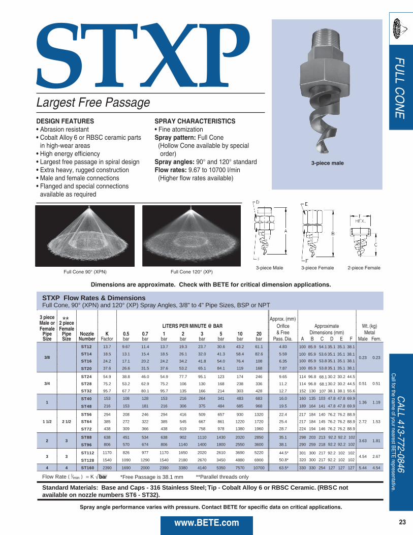
STXP
STXP Flow Rates & Dimensions Full Cone, 90° (XPN) and 120° (XP) Spray Angles, 3/8" to 4" Pipe Sizes, BSP or NPT
3 piece Male or 2 piece
Approx. (mm)
Female Female LITERS PER MINUTE @ BAR Orifice Approximate Wt. (kg)
Pipe Pipe Nozzle K 0.5 0.7 1 2 3 5 10 20 & Free Dimensions (mm) Metal Size Size Number Factor bar bar bar bar bar bar bar bar Pass. Dia. A B C D E F Male Fem.
3/8
ST12 13.7 9.67 11.4 13.7 19.3 23.7 30.6 43.2 61.1 4.83
0.23 0.23 ST14 18.5 13.1 15.4 18.5 26.1 32.0 41.3 58.4 82.6 5.59
ST16 24.2 17.1 20.2 24.2 34.2 41.8 54.0 76.4 108 6.35
ST20 37.6 26.6 31.5 37.6 53.2 65.1 84.1 119 168 7.87
3/4
ST24 54.9 38.8 46.0 54.9 77.7 95.1 123 174 246 9.65 114 96.8 30.2 30.2 44.5
0.51 0.51 ST28 75.2 53.2 62.9 75.2 106 130 168 238 336 11.2 114 96.8 30.2 30.2 44.5
ST32 95.7 67.7 80.1 95.7 135 166 214 303 428 12.7 152 130 38.1 38.1 55.6
1 ST40 153 108 128 153 216 264 341 483 683 16.0 160 135 47.8 47.8 69.9
1.36 1.19 ST48 216 153 181 216 306 375 484 685 968 19.5 189 164 47.8 47.8 69.9
1 1/2 2 1/2
ST56 294 208 246 294 416 509 657 930 1320 22.4 217 184 140 76.2 76.2 88.9
2.72 1.53 ST64 385 272 322 385 545 667 861 1220 1720 25.4 217 184 145 76.2 76.2 88.9
ST72 438 309 366 438 619 758 978 1380 1960 28.7 224 194 146 76.2 76.2 88.9
2 3 ST88 638 451 534 638 902 1110 1430 2020 2850 35.1 298 203 213
3.63 1.81 ST96 806 570 674 806 1140 1400 1800 2550 3600 38.1 290 259 218
3 3 ST112 1170 826 977 1170 1650 2020 2610 3690 5220 44.5*
4.54 2.67 ST128 1540 1090 1290 1540 2180 2670 3450 4880 6900 50.8*
4 4 ST160 2390 1690 2000 2390 3380 4140 5350 7570 10700 63.5* 330 330 254 127 127 127 5.44 4.54
Flow Rate ( l ⁄min ) = *Free Passage is 38.1 mm
Standard Materials: Base and Caps - 316 Stainless Steel; Tip - Cobalt Alloy 6 or RBSC Ceramic. (RBS C notavailable on nozzle numbers ST6 - ST32).
100 85.9 54.1 35.1 35.1 38.1
100 85.9 53.6 35.1 35.1 38.1
100 85.9 53.8 35.1 35.1 38.1
100 85.9 53.8 35.1 35.1 38.1
68.1
68.1
107
103
141
92.2 92.2 102
92.2 92.2 102
301 300 217 92.2 102 102
320 300 217 92.2 102 102
**Parallel threads only
**
K √ barbbabar
Largest Free PassageDESIGN FEATURES• Abrasion resistant• Cobalt Alloy 6 or RBSC ceramic partsin high-wear areas
• High energy efficiency• Largest free passage in spiral design• Extra heavy, rugged construction• Male and female connections• Flanged and special connectionsavailable as required
SPRAY CHARACTERISTICS• Fine atomizationSpray pattern: Full Cone(Hollow Cone available by specialorder)
Spray angles: 90° and 120° standard Flow rates: 9.67 to 10700 l/min(Higher flow rates available)
Full Cone 90° (XPN) Full Cone 120° (XP)3-piece Female 2-piece Female3-piece Male
3-piece male
Dimensions are approximate. Check with BETE for critical dimension applications.
Spray angle performance varies with pressure. Contact BETE for specific data on critical applications.

TO ORDER
:specify pipe size, connection type, nozzle
number, spray angle, and material.
24 www.BETE.com
FULL CONE WL
WL Flow Rates and DimensionsFull Cone, 30°, 60°, 90° and 120° Spray Angles, BSP or NPT
LITERS PER MINUTE @ BAR Approx. Dimensions for
Pipe Nozzle K 0.7 1 2 3 5 10 15 20 Orifice Metal Only (mm) Wt. (g)Size Number Factor bar bar bar bar bar bar bar bar Dia. (mm) A B C D Metal Plas.
1/8*
WL 1/4** 0.587 0.497 0.587 0.814 0.984 1.25 1.73 2.10 2.40 1.09
22.2 28.6 11.1 14.3 28.4 7.1WL 1/2 1.17 0.993 1.17 1.63 1.97 2.50 3.47 4.19 4.80 1.40
WL 3/4 1.76 1.49 1.76 2.44 2.95 3.75 5.20 6.29 7.20 1.83
1/4WL 1 2.35 1.99 2.35 3.25 3.94 5.01 6.93 8.39 9.60 2.08
27.0 34.9 14.2 17.5 42.5 10.6WL 1 1/2 3.52 2.98 3.52 4.88 5.91 7.51 10.4 12.6 14.4 2.77
3/8
WL 2 4.70 3.97 4.70 6.51 7.87 10.0 13.9 16.8 19.2 3.18
31.8 38.1 17.5 22.2 56.7 14.2WL 3 7.05 5.96 7.05 9.76 11.8 15.0 20.8 25.2 28.8 3.96
WL 4 9.40 7.95 9.40 13.0 15.7 20.0 27.7 33.6 38.4 4.78
1/2
WL 5 11.7 9.93 11.7 16.3 19.7 25.0 34.7 41.9 48.0 5.16
38.1 50.8 22.2 28.6 85.1 28.4WL 6 14.1 11.9 14.1 19.5 23.6 30.0 41.6 50.3 57.6 5.56
WL 7 16.4 13.9 16.4 22.8 27.6 35.0 48.5 58.7 67.2 5.79
3/4
WL 8 18.8 15.9 18.8 26.0 31.5 40.0 55.5 67.1 76.8 5.94
44.5 54.0 28.6 34.9 170 42.5WL 10 23.5 19.9 23.5 32.5 39.4 50.1 69.3 83.9 96.0 7.14
WL 12 28.2 23.8 28.2 39.0 47.2 60.1 83.2 101 115 7.92
1WL 15 35.2 29.8 35.2 48.8 59.1 75.1 104 126 144 8.33
55.6 60.3 34.9 41.3 397 99.2WL 20 47.0 39.7 47.0 65.1 78.7 100 139 168 192 9.53
Flow Rate ( l⁄min ) = K ( bar )0.47
Standard Materials: Brass, 303 Stainless Steel, 316 Stainless Steel, PVC, Polypropylene, and PTFE
Male orFemale
Low Flow/Full Cone DESIGN FEATURES• Advanced whirl plate design producesextremely uniform coverage
• Male and female connections
SPRAY CHARACTERISTICS• Medium to coarse atomizationSpray pattern: Full Cone. Square pattern available
Spray angles: 30°, 60°, 90°, and 120° standard
Flow rates: 0.497 to 192 l/min
Full Cone 90° Full Cone 120° Female Metal Male Metal
Metal
Dimensions are approximate. Check with BETE for critical dimension applications.
*1/8" PTFE and Polypropylene not available in 120°.**1/8 WL-1/4 not available in Polypropylene.
Spray angle performance varies with pressure. Contact BETE for specific data on critical applications.

25www.BETE.com
CALL 413-772-0846
Call for the nam
e of your nearest BETE representative.
FULL C
ONE
DESIGN FEATURES• 1/8 and 1/4 pipe connection sizes• Ultimate clog-resistant design, with the
largest free passage available in an axial, full-cone nozzle
• Unique, S-shaped internal vanes allow free passage of particles
• High-energy efficiency• Easily handles dirty, contaminated liquids
• Male connections• Nozzle body available in Brass, 303, 316 Stainless Steel
• Vanes are 316 Stainless Steel for optimum wear and corrosion resistance
SPRAY CHARACTERISTICS• High reliability spray performanceunder the most difficult conditions
• Uniform spray distributionSpray pattern: Full ConeSpray angles: Narrow (N), Medium (M),Wide (W)Flow rates: 0.44 to 7.94 L/min
Narrow (N) Wide (W)Medium (M)
MaxiPass L (MPL) Flow Rates
Male Pipe Size
K Factor NozzleNumber
LITERS PER MINUTE @ BAR
0.7 BAR 1 BAR 2 BAR 3 BAR 4 BAR 5 BAR 6 BAR
1/8
0.514 MPL0.21 0.44 0.51 0.69 0.82 0.93 1.03 1.11
0.734 MPL0.30 0.63 0.73 0.99 1.18 1.33 1.47 1.59
1.03 MPL0.42 0.88 1.03 1.39 1.65 1.87 2.06 2.23
1.39 MPL0.57 1.19 1.39 1.87 2.23 2.52 2.78 3.00
1/4
1.88 MPL0.77 1.61 1.88 2.53 3.02 3.41 3.76 4.06
2.74 MPL1.12 2.35 2.74 3.69 4.39 4.97 5.47 5.92
3.69 MPL1.51 3.17 3.69 4.97 5.92 6.70 7.37 7.97
Spray Angle and Dimensions
NozzleNumber
N sprayangle
M sprayangle
W sprayangle Approx. Free Passage Dia. (mm) Approx. Dimensions (mm)
Wt. (g) Metal3 BAR 3 BAR 3 BAR N M W length hex size
MPL0.21 51 77 129 0.94 0.91 0.91
18 11.1 9MPL0.30 53 86 134 1.1 0.99 1.1
MPL0.42 51 90 128 1.3 1.2 1.1
MPL0.57 61 92 127 1.5 1.4 1.3
MPL0.77 62 90 125 1.7 1.7 1.722 14.3 18MPL1.12 60 92 124 2.2 2.1 2.1
MPL1.51 70 97 123 2.7 2.3 2.3
Dimensions are approximate. Check with BETE for critical dimension applications.
Spray angle performance varies with pressure. Contact BETE Applications Engineering for specific data on critical applications.
Flow Rate (L/min) = K (BAR) 0.43
A B
B
A
MaxiPass L Ordering Nomenclature
1/8 MPL0.21M -B - 316pipe connection size
series
spray angle
BSP thread connection
material
flow rating
cutaway view
MaxiPass® LLow Flow, Full Cone, Maximum Free Passage

TO ORDER
:specify pipe size, connection type, nozzle
number, spray angle, and material.
26 www.BETE.com
FULL CONE
MaxiPass Flow Rates and DimensionsFull Cone, 30° (NN), 60° (N), 90° (M), and 120° (W) Spray Angles, 3/8" to 4" Pipe Sizes, BSP or NPT
Male orApprox. Approx. Dimensions (mm)
Female LITERS PER MINUTE @ BAR Free Overall Length Wt.**
Pipe Nozzle K 0.2 0.3 0.5 0.7 1 2 3 5 Passage 30° 60° 90° 120° (kg)Size Number Factor bar bar bar bar bar bar bar bar Dia. (mm) A A A A B Metal
3/8*MP125 5.53 2.60 3.14 3.99 4.68 5.53 7.66 9.27 11.8 3.18
- 38.1 38.1 38.1 22.20.09
MP156 8.79 4.13 4.99 6.35 7.43 8.79 12.2 14.7 18.7 3.97 0.09MP187 12.7 5.96 7.21 9.17 10.7 12.7 17.6 21.3 27.1 4.76 0.07
1/2*MP187 12.7 5.96 7.21 4.76
47.6 47.6 47.6 25.40.13
MP218 20.2 9.48 11.5 14.6 17.1 20.2 28.0 33.9 43.0 5.56 0.11MP250 22.7 10.7 12.9 16.4 19.2 22.7 31.4 38.0 48.4 6.35 0.11
3/4
MP281 27.9 13.1 15.8 20.1 23.6 27.9 38.6 46.8 59.4 7.14
102 63.5 60.3 63.5 31.8
0.23MP312 33.8 15.9 19.2 24.4 28.6 33.8 46.8 56.6 72.0 7.94 0.23MP343 41.4 19.4 23.5 29.9 35.0 41.4 57.3 69.4 88.2 8.73 0.20MP375 48.8 22.9 27.7 35.2 41.3 48.8 67.6 81.8 104 9.53 0.20
1MP375 48.8 9.53
111 74.6 74.6 74.6 38.10.35
MP406 58.5 27.5 33.2 42.2 49.2 58.5 81.0 98.0 125 10.3 0.33MP437 68.4 32.1 38.8 49.4 57.8 68.4 94.7 115 146 11.1 0.33
1 1/4
MP437 68.4 11.1MP500 87.9 41.3 49.9 63.5 74.3 87.9 122 148 187 12.7 137 85.7 85.7 85.7 50.8MP531 97.6 45.8 55.4 70.5 82.5 97.6 135 164 208 13.5MP562 107 50.2 60.8 77.3 90.5 107 148 179 228 14.3
1 1/2
MP562 107 13.97MP593 122 57.3 69.3 88.1 103 122 169 205 260 15.1MP625 130 61.0 73.8 93.9 110 130 180 218 277 15.9 184 111 111 111 57.2MP656 158 74.2 89.7 114 134 158 219 265 337 16.7MP687 166 77.9 94.3 120 140 166 230 278 354 17.5
Flow Rate ( L⁄min ) = K ( bar ) 0.47 ** Weights given are for 60°, 90°, and 120° (PTFE not available in 3/8" and 1/2" sizes. Cobalt A6 not available in 3/8”.)
Standard Materials: Brass, 316 Stainless Steel, PVC, Polypropylene, and PTFE
M
* **Weights given are for 60°, 90°, and 120°
S Brass, 316 Stainless Steel, PVC, Polypropylene, and PTFE.
0.61
0.91
1
9.17 10.7 12.7 17.6 21.3 27.1
22.9 27.7 35.2 41.3 48.8 67.6 81.8 104
32.1 38.8 49.4 57.8 68.4 94.7 115 146
50.2 60.8 77.3 90.5 107 148 179 228
1
-
DESIGN FEATURES• Ultimate clog-resistant design withlargest free passage available in a fullcone nozzle
• Two unique S-shaped internal vanesallow free passage of particles
• High energy efficiency• Easily handles dirty, lumpy liquids• Male and female connections• Flanged connection available• Patented design
SPRAY CHARACTERISTICS• High reliability spray performance under the most difficult conditions
Spray pattern: Full Cone(Square patterns to special order)
Spray angles: 30°, 60°, 90° and 120°Flow rates: 2.60 to 3540 L/min(Flow rates up to 17,000 L/min available;call BETE Applications Engineering for details.)
Full Cone 30° (NN) Full Cone 60° (N) Full Cone 120° (W)Full Cone 90° (M)
The spray angle of wide and medium angle whirl nozzles is affected by increasing pressure. Contact BETE Applications Engineering when using the MaxiPass above 3 bar (40 PSI).
Dimensions are approximate. Check with BETE for critical dimension applications.
MaxiPass®
Maximum Free Passage
Wide Angle Metal
Spray angle performance varies with pressure. Contact BETE for specific data on critical applications.
*3/8” and 1/2” sizes: 30° not available, 60° not available in plastic

27www.BETE.com
CALL 413-772-0846
Call for the nam
e of your nearest BETE representative.
FULL C
ONE
A cutaway view ofthe MaxiPassnozzle showing theS-shaped vanesthat enable thenozzle tosuccessfully handlelarge particleswithout clogging.
MaxiPassFree Passage
Traditional Full ConeFree Passage
A comparison of the free passage available with the BETEMaxiPass nozzle compared to the free passage of a traditionalfull cone nozzle. The BETE MaxiPass is designed to pass solidparticles that are 2-3 times larger in diameter than particles thatwill pass through a traditional full cone nozzle.
60° (N), 90° (M), and 120° (W) Spray Angles, 3/8" to 4" Pipe Sizes, BSP or NPT
M
** Weights given are for 60°, 90°, and 120° (P
MaxiPass Flow Rates and DimensionsFull Cone, 30°(NN), 60° (N), 90°(M), and 120°(W) Spray Angles, 3/8" to 4" Pipe Sizes, BSP or NPT
Male orApprox. Approx. Dimensions (mm)
Female LITERS PER MINUTE @ BAR Free Overall Length Wt.**
Pipe Nozzle K 0.2 0.3 0.5 0.7 1 2 3 5 Passage 30° 60° 90° 120° (kg)
Size Number Factor bar bar bar bar bar bar bar bar Dia. (mm) A A A A C* Metal
2
MP750 202 94.8 115 146 171 202 280 339 430 19.1
MP812 221 104 126 160 187 221 306 370 471 20.6 210 183 146 159 66.8 1.59
MP875 273 129 155 197 231 273 378 458 582 22.2
MP937 306 144 174 221 259 306 424 513 652 23.8 229 194 152 165 82.6
MP1000 358 168 203 259 303 358 496 600 763 25.4 1.70
MP1125 439 206 249 317 371 439 608 736 935 28.6262 194 152 171 82.6
2 1/2
MP1125 439 28.6 267 213 165 178 82.6 2.04
MP1250 527 247 299 381 446 527 730 883 1120 31.5 305 244 165 181 82.6 2.04
MP1375 632 297 359 456 535 632 875 1060 1350 34.9 305 244 213 229 102 2.84
MP1500 774 363 440 559 655 774 1070 1230 1650 38.1 330 267 213 229 102 2.84
3
MP1500 774 37.1 343 279 229 248 121 3.29
MP1625 911 428 517 658 770 911 1260 1530 1940 41.3 343 279 229 251
MP1750 1040 488 591 751 880 1040 1440 1740 2220 44.5 343 279 229 251
4
MP1750 1040 44.5 406 356 225 248 121 3.63
MP1875 1170 549 664 845 989 1170 1620 1960 2490 47.6 406 356 225 248 121 3.63
MP2000 1370 643 778 989 1160 1370 1900 2300 2920 49.8 406 356 286 311 152 7.26
MP2125 1530 718 869 1100 1290 1530 2120 2560 3260 54.0 406 356 286 311 152 7.26
MP2250 1660 779 943 1200 1400 1660 2300 2780 3540 57.2 406 356 286 311 152 7.26
Flow Rate ( L⁄min ) = K ( bar ) 0.47 *C dimension for 30° (NN) is larger **Weights given are for 60°, 90°, and 120°
Standard Materials: Brass, 316 Stainless Steel, PVC, Polypropylene, and PTFE.
121 3.29
121 3.29
MP1000 358 25.4 262 194 152 168 82.6 2.04
9
168 203 259 303 358 496 600 763
206 249 317 371 439 608 736 935
363 440 559 655 774 1070 1230 1650
488 591 751 880 1040 1440 1740 2220
For plastic dimensions, please call BETE Customer Service.Dimensions are approximate. Check with BETE for critical dimension applications.
Spray angle performance varies with pressure. Contact BETE for specific data on critical applications.
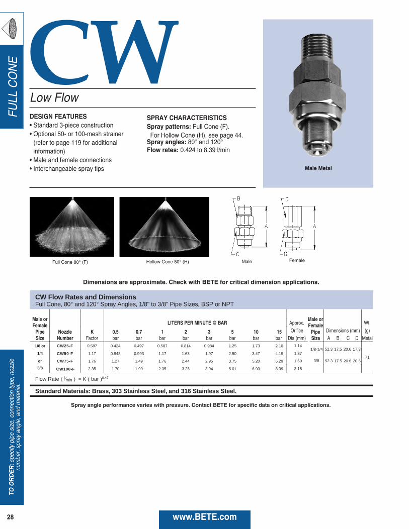
TO ORDER
:specify pipe size, connection type, nozzle
number, spray angle, and material.
28 www.BETE.com
FULL CONE CW
CW Flow Rates and Dimensions Full Cone, 80° and 120° Spray Angles, 1/8" to 3/8" Pipe Sizes, BSP or NPT
Male or Female LITERS PER MINUTE @ BAR Approx. Wt.
Pipe Nozzle K 0.5 0.7 1 2 3 5 10 15 Orifice Dimensions (mm) (g) Size Number Factor bar bar bar bar bar bar bar bar Dia.(mm) A B C Metal 1/8 or CW25-F 0.587 0.424 0.497 0.587 0.814 0.984 1.25 1.73 2.10 1.14
71 1/4 CW50-F 1.17 0.848 0.993 1.17 1.63 1.97 2.50 3.47 4.19 1.37
or CW75-F 1.76 1.27 1.49 1.76 2.44 2.95 3.75 5.20 6.29 1.60
3/8 CW100-F 2.35 1.70 1.99 2.35 3.25 3.94 5.01 6.93 8.39 2.18
Flow Rate ( l ⁄min ) = K ( bar )0.47
Standard Materials: Brass, 303 Stainless Steel, and 316 Stainless Steel.
D
17.5 20.6 17.3 52.3
17.5 20.6 20.6 52.3
1/8-1/4
3/8
Male or Female
Pipe Size
Low FlowDESIGN FEATURES• Standard 3-piece construction• Optional 50- or 100-mesh strainer(refer to page 119 for additionalinformation)
• Male and female connections• Interchangeable spray tips
SPRAY CHARACTERISTICSSpray patterns: Full Cone (F).For Hollow Cone (H), see page 44.
Spray angles: 80° and 120°Flow rates: 0.424 to 8.39 l/min
Full Cone 80° (F) Hollow Cone 80° (H)
Male Metal
Male Female
Dimensions are approximate. Check with BETE for critical dimension applications.
Spray angle performance varies with pressure. Contact BETE for specific data on critical applications.

29www.BETE.com
CALL 413-772-0846
Call for the nam
e of your nearest BETE representative.
FULL C
ONE
DESIGN FEATURES• No internal parts, clog-resistant• Uniform distribution• Male and female connections • Large free passage
SPRAY CHARACTERISTICSSpray pattern: Full ConeSpray angle: 90° and 110°Flow rates: 0.50 to 223 L/min
Right Angle Full Cone
WTZ Flow Rates and DimensionsFull Cone, 90° and 110° Spray Angles, 1/4", 3/8", 1/2”, 3/4”, and 1”Pipe Size, BSP or NPT
WTZ
Spray angle performance varies with pressure. Contact BETE for specific data on critical applications.
Full Cone 90° Full Cone 110°
Flow Rate (L/min) = K Ö bar
Standard Materials: Brass, PVC, 303 Stainless Steel and 316 Stainless Steel.
Male or LITERS PER MINUTE @ BAR Female Approx. Dimensions (mm)
Pipe Nozzle K 0.5 1 2 3 5 7 10 Orifice Metal OnlySize Number Factor bar bar bar bar bar bar bar Dia. (mm) A B C D
WTZ 50 1.13 0.80 1.13 1.60 1.96 2.53 2.99 3.58 1.901/4” WTZ 56 1.27 0.90 1.27 1.80 2.20 2.84 3.36 4.02 2.00 33 25 20 16
WTZ 62 1.41 1.00 1.41 2.00 2.45 3.16 3.74 4.47 2.10WTZ 77 1.77 1.25 1.77 2.50 3.06 3.95 4.67 5.59 2.30
WTZ 98 2.23 1.58 2.23 3.15 3.86 4.98 5.90 7.05 2.60WTZ 120 2.83 2.00 2.83 4.00 4.90 6.33 7.48 8.95 3.00WTZ 150 3.53 2.50 3.53 5.00 6.12 7.90 9.35 11.2 3.30WTZ 170 3.96 2.80 3.96 5.60 6.86 8.86 10.5 12.5 3.50
3/8" WTZ 200 4.46 3.15 4.46 6.30 7.72 10.0 11.8 14.1 3.70 38 28 30 19WTZ 250 5.66 4.00 5.66 8.00 9.80 12.7 15.0 17.9 4.15WTZ 280 6.36 4.50 6.36 9.00 11.0 14.2 16.8 20.1 4.40WTZ 310 7.07 5.00 7.07 10.0 12.3 15.8 18.7 22.4 4.65WTZ 390 8.84 6.25 8.84 12.5 15.3 19.8 23.4 28.0 5.20WTZ 500 11.3 8.00 11.3 16.0 19.6 25.3 29.9 35.8 5.80
WTZ 620 14.1 10.0 14.1 20.0 24.5 31.6 37.4 44.7 7.301/2" WTZ 780 17.7 12.5 17.7 25.0 30.6 39.5 46.8 55.9 8.00 47 35 38 25
WTZ 980 22.3 15.8 22.3 31.5 38.6 49.8 58.9 70.4 8.70WTZ1120** 25.5 18.1 25.5 36.1 44.2 57.1 67.5 80.7 9.87WTZ1280** 29.2 20.6 29.2 41.3 50.5 65.2 77.2 92.2 10.7WTZ1440** 32.8 23.2 32.8 46.4 56.8 73.4 86.8 103.8 9.93WTZ1200 27.3 19.3 27.4 38.7 47.4 61.2 72.4 86.5 8.51
3/4”* WTZ1500 34.2 24.2 34.2 48.3 59.2 76.4 90.4 108 10.5 76 51 51 51WTZ1900 43.3 30.6 43.3 61.2 75.0 96.8 115 137 11.9WTZ2200 50.1 35.5 50.1 70.9 86.8 112 133 159 12.7 81 56 65 63WTZ3100 70.6 50.0 70.7 99.9 122 158 187 223 13.5
1”*
*Male threads ONLY. Female threads available on request. **90° Spray Angle ONLY; other angles available on request.
D
C
AB
Metal
Metal
Dimensions are approximate. Check with BETE for critical dimension applications.
Spray angle performancevaries with pressure.
Contact BETE for specificdata on
critical applications.
AB
C
D
3/4” and 1”

TO ORDER
:specify pipe size, connection type, nozzle
number, spray angle, and material.
30 www.BETE.com
FULL CONE EZTF WL
LITERS PER MINUTE @ BAR Approx. Approx. AssemblyPipe Nozzle K 0.3 0.5 0.7 1 2 3 5 7 10 15 20 30 Orifice Dim. (mm) Wt.Size Number Factor bar bar bar bar bar bar bar bar bar bar bar bar Dia. (mm) Hex Length (g)
1/8” EZTF6 3.19 1.75 2.26 2.67 3.19 4.51 5.53 7.13 8.44 10.1 12.4 14.3 17.5 2.38 1/8” 22.4 41.4 62TO EZTF8 5.93 3.25 4.19 4.96 5.93 8.38 10.3 13.2 15.7 18.7 22.9 26.5 32.5 3.181/2” EZTF10 9.12 4.99 6.45 7.63 9.12 12.9 15.8 20.4 24.1 28.8 35.3 40.8 49.9 3.97 1/4” 22.4 44.5 62 EZTF12 13.7 7.49 9.7 11.4 13.7 19.3 23.7 30.6 36.2 43.2 53.0 61.1 74.9 4.76
1/4” EZTF14 18.5 10.1 13.1 15.4 18.5 26.1 32.0 41.3 48.8 58.4 71.5 82.6 101 5.56 3/8” 22.4 46.0 74TO EZTF16 24.2 13.2 17.1 20.2 24.2 34.2 41.8 54.0 63.9 76.4 93.6 108 132 6.351/2” EZTF20 37.6 20.6 26.6 31.5 37.6 53.2 65.1 84.1 99.5 119 146 168 206 7.94 1/2” 22.4 47.5 82
Flow Rate (l/min) = K Ö bar
Standard Materials: Brass; Viton gaskets standard. 316 Stainless Steel available upon request.
DESIGN FEATURES• Nozzles can be changed in secondswithout tools
• Three part nozzle, base, gasket andinterchangeable tip
• Exclusive ramped engagement forefficient, automatic alignment
• Threaded adapters will accommodateother standard BETE nozzles. Shut-offplugs are also available
• Sanitary EZs are available with weldconnection and no knurling
SPRAY CHARACTERISTICS• Available in six standard tips: EZTF;EZWL; EZWT; EZFF; EZNF; EZSPN
More EZ tips:Hollow Cone: page 46Flat Fan: pages 66 and 67
Flow rates: 0.13 to 206 l/minSpray Angle:
EZTF: 60°, 90°, 120°, 150°, and 170° EZWL: 30°, 60°, 90°, 120°
EZ Change Quick Connection System
EZTF
NPT / R NPT / R NPT / R NPT / R
FNPT / RPFNPT / RPFNPT / RPFNPT / RP
25.4mm 32.5mm
42.4mm
31.0mm
30.5mm 28.7mm 22.6mm
26.4mm29.5mm
26.4mm29.5mm
31.0mm36.8mm
EZTF Flow Rates and DimensionsFull Cone Spiral 60° (NN), 90° (FCN), 120° (FC), 150°, or 170° Spray Angle 1/8” to 1/2” BSP or NPT
LITERS PER MINUTE @ BAR Approx.
Approx. AssemblyPipe Nozzle K 0.2 0.5 0.7 1 2 3 5 Orifice Pipe Dim. (mm) Wt.Size Number Factor bar bar bar bar bar bar bar Dia (mm) Size Hex Length (g)
EZWL 1/4 0.587 0.276 0.424 0.497 0.587 0.814 0.984 1.25 1.09 EZWL 1/2 1.17 0.551 0.848 0.993 1.17 1.63 1.97 2.50 1.40 1/8” 22.4 41.4 621/8” EZWL 3/4 1.76 0.827 1.27 1.49 1.76 2.44 2.95 3.75 1.83 EZWL1 2.35 1.10 1.70 1.99 2.35 3.25 3.94 5.01 2.08 1/4” 22.4 44.5 62TO EZWL 1 1/2 3.52 1.65 2.54 2.98 3.52 4.88 5.91 7.51 2.77 EZWL2 4.70 2.21 3.39 3.97 4.70 6.51 7.87 10.0 3.18 3/8” 22.4 46.0 741/2” EZWL3 7.05 3.31 5.09 5.96 7.05 9.76 11.8 15.0 3.96 EZWL4 9.40 4.41 6.78 7.95 9.40 13.0 15.7 20.0 4.78 1/2” 22.4 47.5 82 EZWL5 11.7 5.51 8.48 9.93 11.7 16.3 19.7 25.0 5.16 EZWL6 14.1 6.62 10.2 11.9 14.1 19.5 23.6 30.0 5.56
Flow Rate (l/min ) = K (bar) 0.47 Note: Square pattern also availableStandard Materials: 303 Stainless Steel, 316 Stainless Steel, Brass; Viton gaskets standard.
EZWL Flow Rates and DimensionsFull Cone Whirl 30°, 60°, 90°, 120° Spray Angle 1/8” to 1/2” BSP or NPT
120° Full Cone 90° Full Cone Spiral

31www.BETE.com
FULL C
ONE
LITERS PER MINUTE @ BAR
Available ApproxNozzle Spray K 0.5 0.7 1 2 3 5 7 10 Pipe Body Dim. (mm) Wt.Number Angle Factor bar bar bar bar bar bar bar bar Size Color A B (g)SF31FC 35° 7.596 5.45 6.40 7.60 10.6 12.9 16.4 19.3 22.9 1” blue 83.8 43.2 62.4SF32FC 80° 7.855 5.63 6.62 7.86 11.0 13.3 17.0 20.0 23.7 1-1/4” red 86.4 48.3 62.4SF102FC 65° 25.02 17.9 21.1 25.0 34.9 42.4 54.2 63.7 75.6 1-1/2” purple 91.4 50.8 62.4 2” green 94.0 55.9 62.4
Flow Rate (l/min ) = K (bar) 0.48
Standard Materials: Polypropylene, 302 Stainless Steel clamp, EPDM seal.Optional Materials: 303 Stainless Steel clamp, Viton seal.
DESIGN FEATURES• Nozzles can be quickly changed andaligned by hand without tools
• Clamp-on adapter fits any style nozzle• Quick set-up system features special“Snap-in” tips
• Polypropylene, resistant to most acidsand alkalies
• Double clamp base or adapter availablefor higher pressure operation
SPRAY CHARACTERISTICS• Quick Set-up System can be providedwith fan, hollow or full cone spray tips
• Full 45° alignment of spray without tools
More SF Nozzle Systems:Hollow Cone: page 48Flat Fan: page 68
Flow rates: 1.61 to 75.6 l/minSpray angles:
Snap Release Nozzle SystemSF
NOTE: Drill 16.7mm (21/32”) hole in pipe to install SF.
NOTE: Maximum recommended pressures for SF assemblies: With single clamp 5 bar for 1” pipe; 3.5 bar for 1-1/4” and 1-1/2” pipe; and 2bar for 2” pipe; with double clamp up to 10 bar.
Spray angle performance varies with pressure. Contact BETE for specific data on critical applications.
80° Full Cone
A
B
2.1”45°
CLAMP-ON ADAPTER• Available for 1”, 1-1/4”, 1-1/2” and 2” pipe.• Available with 1/8”, 1/4”, 3/8”, 1/2” NPT female threads; or 1/8” BSP female threads
• Available with single or double clamp.• TO ORDER ADAPTER Specify: Pipe Size, thread size,
thread type, number of clamps, materials.
Double Clamp Adapter with Spiral Nozzle
Double-Clamp Adapter
Single-Clamp Base
Retainer Cap“SNAP-IN”Threaded Swivel Ball
Available with 1/8”, 1/4”, 3/8”, 1/2”NPT or BSP
Female threads
Single-Clamp Adapter
“SNAP-IN”Full Cone Nozzle Tip
CALL 413-772-0846
Call for the nam
e of your nearest BETE representative.
SF Flow Rates and DimensionsSF Full Cone 35°, 65° and 80° Spray Angles 1”, 1-1/4”, 1-1/2” and 2”

TO ORDER
:specify pipe size, connection type, nozzle
number, spray angle, and material.
32 www.BETE.com
FULL CONESC Flow Rates and Dimensions
F
BAR F
R ( L ) = K b 0
S 316 Stainless Steel
SC Flow Rates & Dimensions Full Cone, Narrow 60° (N), Medium 90° (M) and Wide 120° (W) Spray Angles , 3/4" to 6" Pipe Sizes, BSP or NPT
Male or Approx.
Female Available LITERS PER MINUTE @ BAR Approx. Free Wt.
Pipe Nozzle Spray Angles K 0.2 0.3 0.7 1 2 3 5 7 Orifice Pass. Dim. (mm) (kg) Size Number 60° 90° 120° Factor bar bar bar bar bar bar bar bar Dia. (mm) Dia. (mm) A B Metal
3/4
SC 2.5 60° 13.3 6.25 7.57 11.3 13.3 18.5 22.3 28.4 33.3 4.76
4.83 50.8 31.0 0.23
SC 3 60° 90° 16.0 7.50 9.08 13.5 16.0 22.1 26.8 34.1 39.9 5.16
SC 4 60° 90° 120° 21.3 10.0 12.1 18.0 21.3 29.5 35.7 45.4 53.2 7.14
SC 6 120° 32.0 15.0 18.2 27.0 32.0 44.3 53.6 68.1 79.8 7.54
SC 7 90° 37.3 17.5 21.2 31.6 37.3 51.7 62.5 79.5 93.1 8.89
1
SC 4.2 60° 22.4 10.5 12.7 18.9 22.4 31.0 37.5 47.7 55.9 6.35 6.35
73.2 38.1 0.36
SC 7 60° 37.3 17.5 21.2 31.6 37.3 51.7 62.5 79.5 93.1 8.33 7.87
SC 8 60° 42.6 20.0 24.2 36.1 42.6 59.1 71.5 90.9 106 8.89 7.87
SC 9 90° 120° 48.0 22.5 27.2 40.6 48.0 66.4 80.4 102 120 10.2 7.87
SC 10 90° 53.3 25.0 30.3 45.1 53.3 73.8 89.3 114 133 10.7 7.87
SC 11 120° 58.6 27.5 33.3 49.6 58.6 81.2 98.3 125 146 11.2 7.87
SC 12 90° 120° 64.0 30.0 36.3 54.1 64.0 88.6 107 136 160 11.7 7.87
1 1/4
SC 6 60° 32.0 15.0 18.2 27.0 32.0 44.3 53.6 68.1 79.8 7.62 7.62
88.9 47.6 0.59
SC 10 60° 53.3 25.0 30.3 45.1 53.3 73.8 89.3 114 133 9.92 9.65
SC 12 60° 64.0 30.0 36.3 54.1 64.0 88.6 107 136 160 10.7 9.65
SC 14 90° 74.6 35.0 42.4 63.1 74.6 103 125 159 186 11.7 9.65
SC 16 120° 85.3 40.0 48.4 72.1 85.3 118 143 182 213 12.3 9.65
SC 17 90° 90.6 42.5 51.5 76.6 90.6 126 152 193 226 13.5 9.65
SC 20 90° 120° 107 50.0 60.5 90.1 107 148 179 227 266 15.9 9.65
Flow Rate ( l ⁄min ) = K ( bar )0.47
Standard Materials: Brass, Carbon Steel, and 316 Stainless Steel
90°
120°
90°
120°
90°
120° 90°
120° 90°
60°
60° 120°
90° 60°
90°
90°
90° 120°
60° 120°
90° 60°
60° 120°
Metal Alloy LineDESIGN FEATURES• Complete line of full cone nozzlesmade in cast metal alloys
• Internal removable vane available• Male and female connections• Flanged connections available• For plastic nozzles, see NC (pp. 34,35), or MaxiPass (pp. 26, 27)
SPRAY CHARACTERISTICS• Spray pattern: Full Cone with uniformdistribution. For square spray patterns,please contact BETE.
• Spray angles: 60°, 90°, and 120°• Flow rates: 6.25 to 8180 l/min
Full Cone 90°(M) Full Cone 120° (W) 60° / 90° / 120° Female 60° / 90° / 120° Male
Male
Dimensions are approximate. Check with BETE for critical dimension applications.
Spray angle performance varies with pressure. Contact BETE for specific data on critical applications.
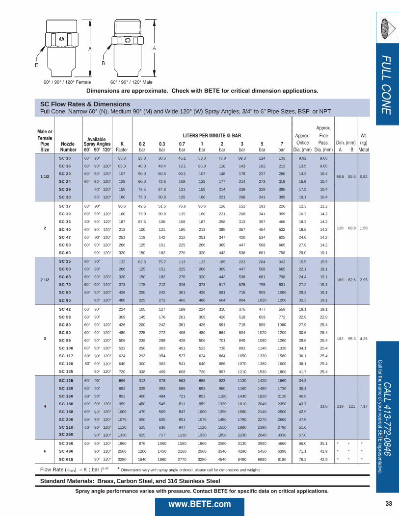
33www.BETE.com
FULL C
ONE
CALL 413-772-0846
Call for the nam
e of your nearest BETE representative.
SC Flow Rates & Dimensions Full Cone, Narrow 60° (N), Medium 90° (M) and Wide 120° (W) Spray Angles, 3/4" to 6" Pipe Sizes, BSP or NPT
Male or Approx.
Female Available LITERS PER MINUTE @ BAR Approx. Free Wt.
Pipe Nozzle Spray Angles K 0.2 0.3 0.7 1 2 3 5 7 Orifice Pass. Dim. (mm) (kg) Size Number 60° 90° 120° Factor bar bar bar bar bar bar bar bar Dia. (mm) Dia. (mm) A B Metal
1 1/2
SC 10 60° 53.3 25.0 30.3 45.1 53.3 73.8 89.3 114 133 9.92 9.65
98.6 55.6 0.82
SC 16 60° 90° 120° 85.3 40.0 48.4 72.1 85.3 118 143 182 213 13.5 9.65
SC 20 60° 90° 120° 107 50.0 60.5 90.1 107 148 179 227 266 14.3 10.4
SC 24 90° 120° 128 60.0 72.6 108 128 177 214 273 319 15.9 10.4
SC 29 120° 155 72.5 87.8 131 155 214 259 329 386 17.5 10.4
SC 30 90° 160 75.0 90.8 135 160 221 268 341 399 19.1 10.4
2
SC 17 60° 90.6 42.5 51.5 76.6 90.6 126 152 193 226 12.3 12.2
130 69.9 1.50
SC 30 60° 160 75.0 90.8 135 160 221 268 341 399 16.3 14.2
SC 35 90° 187 87.6 106 158 187 258 313 397 466 18.3 14.2
SC 40 90° 213 100 121 180 213 295 357 454 532 19.8 14.2
SC 47 120° 251 118 142 212 251 347 420 534 625 24.6 14.2
SC 50 90° 120° 266 125 151 225 266 369 447 568 665 27.9 14.2
SC 60 90° 120° 320 150 182 270 320 443 536 681 798 29.0 19.1
2 1/2
SC 25 60° 133 62.5 75.7 113 133 185 223 284 333 15.5 15.5
160 82.6 2.95
SC 50 60° 266 125 151 225 266 369 447 568 665 22.1 19.1
SC 60 90° 320 150 182 270 320 443 536 681 798 24.4 19.1
SC 70 90° 120° 373 175 212 316 373 517 625 795 931 27.2 19.1
SC 80 90° 120° 426 200 242 361 426 591 715 909 1060 29.2 19.1
SC 90 90° 120° 480 225 272 406 480 664 804 1020 1200 32.3 19.1
3
SC 42 60° 224 105 127 189 224 310 375 477 559 19.1 19.1
182 95.3 4.26
SC 58 60° 309 145 176 261 309 428 518 659 772 22.9 22.9
SC 80 90° 426 200 242 361 426 591 715 909 1060 27.9 25.4
SC 90 90° 120° 480 225 272 406 480 664 804 1020 1200 30.6 25.4
SC 95 120° 506 238 288 428 506 701 849 1080 1260 28.6 25.4
SC 100 90° 533 250 303 451 533 738 893 1140 1330 34.1 25.4
SC 117 120° 624 293 354 527 624 864 1050 1330 1560 36.1 25.4
SC 120 90° 640 300 363 541 640 886 1070 1360 1600 38.1 25.4
SC 135 90° 120° 720 338 409 608 720 997 1210 1530 1800 41.7 25.4
4
SC 125 60° 666 313 378 563 666 923 1120 1420 1660 34.3
33.8 219 121 7.17
SC 130 60° 693 325 393 586 693 960 1160 1480 1730 35.1
SC 160 90° 853 400 484 721 853 1180 1430 1820 2130 40.6
SC 180 90° 120° 959 450 545 811 959 1330 1610 2040 2390 43.7
SC 188 120° 1000 470 569 847 1000 1390 1680 2140 2500 42.9
SC 200 90° 1070 500 605 901 1070 1480 1790 2270 2660 47.6
SC 210 90° 1120 525 636 947 1120 1550 1880 2390 2790 51.6
SC 250 90° 120° 1330 625 757 1130 1330 1850 2230 2840 3330 57.0
6
SC 350 60° 90° 120° 1860 876 1060 1580 1860 2580 3130 3980 4660 66.0 35.1 * * *
SC 480 90° 120° 2560 1200 1450 2160 2560 3540 4290 5450 6390 71.1 42.9 * * *
SC 615 90° 120° 3280 1540 1860 2770 3280 4540 5490 6980 8180 76.2 42.9 * * *
Flow Rate (l ⁄min ) = K ( bar )0.47 * Dimensions vary with spray angle ordered, please call for dimensions and weights
Standard Materials: Brass, Carbon Steel, and 316 Stainless Steel
90°
60°
90°
120°
90°
90° 120°
60° 120°
60° 120°
90° 60°
60°
90°
90°
60° 120°
60°
60°
60°
90°
90°
120°
60°
90° 60°
120° 60°
90° 60°
120° 60°
90°
90°
60°
60°
90° 60°
120° 60°
120° 60°
60° / 90° / 120° Female 60° / 90° / 120° Male
Dimensions are approximate. Check with BETE for critical dimension applications.
Spray angle performance varies with pressure. Contact BETE for specific data on critical applications.
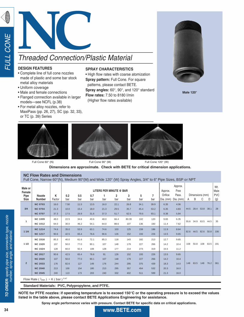
TO ORDER
:specify pipe size, connection type, nozzle
number, spray angle, and material.
34 www.BETE.com
FULL CONE NC
NC Flow Rates and Dimensions Full Cone, Narrow 60°(N), Medium 90°(M) and Wide 120° (W) Spray Angles, 3/4" to 6" Pipe Sizes, BSP o r NPT
Male or Approx.
Female LITERS PER MINUTE @ BAR Approx. Free Wt.
Pipe Nozzle K 0.2 0.5 0.7 1 2 3 5 7 Orifice Pass. Dimensions (mm) (g) Size Number Factor bar bar bar bar bar bar bar bar Dia. (mm) Dia. (mm) A B C D
Male
3/4
NC 0703 16.0 7.50 11.5 13.5 16.0 22.1 26.8 34.1 39.9 6.35 4.06
44.5 28.4 53.8 38.1 28 NC 0704 21.3 10.0 15.4 18.0 21.3 29.5 35.7 45.4 53.2 6.35 4.83
NC 0707 37.3 17.5 26.9 31.6 37.3 51.7 62.5 79.5 93.1 8.38 5.84
1 NC 1009 48.0 22.5 34.6 40.6 48.0 66.4 80.39 102 120 9.65 6.35
55.6 34.9 63.5 44.5 35 NC 1012 64.0 30.0 46.2 54.1 64.0 88.6 107 136 160 11.4 7.62
1 1/4 NC 1214 74.6 35.0 53.9 63.1 74.6 103 125 159 186 11.9 8.64
82.6 44.5 82.6 50.8 106 NC 1217 90.6 42.5 65.4 76.6 90.6 126 152 193 226 13.5 9.65
1 1/2
NC 1516 85.3 40.0 61.6 72.1 85.3 118 143 182 213 12.7 9.65
108 50.8 108 63.5 191 NC 1520 107 50.0 77.0 90.1 107 148 179 227 266 14.2 10.4
NC 1524 128 60.0 92.4 108 128 177 214 273 319 15.5 11.2
2
NC 2017 90.6 42.5 65.4 76.6 91 126 152 193 226 13.5 9.65
148 63.5 148 76.2 361
NC 2020 107 50.0 77.0 90.1 107 148 179 227 266 14.2 10.4
NC 2033 176 82.6 127 149 176 244 295 375 439 18.3 14.0
NC 2040 213 100 154 180 213 295 357 454 532 20.3 16.0
NC 2045 240 113 173 203 240 332 402 511 599 21.3 16.0
Flow Rate ( l ⁄min ) = K ( bar ) 0.47
Standard Materials: PVC, Polypropylene, and PTFE.
M
PVC
Threaded Connection/Plastic MaterialDESIGN FEATURES• Complete line of full cone nozzlesmade of plastic and some bar stockmetal alloy materials
• Uniform coverage• Male and female connections• Flanged connection available in largermodels—see NCFL (p.38)
• For metal alloy nozzles, refer toMaxiPass (pp. 26, 27), SC (pp. 32, 33),or TC (p. 39) Series
SPRAY CHARACTERISTICS• High flow rates with coarse atomizationSpray pattern: Full Cone. For square patterns, please contact BETE.
Spray angles: 60°, 90°, and 120° standard Flow rates: 7.50 to 8180 l/min(Higher flow rates available)
Full Cone 60° (N) Full Cone 90° (M) Full Cone 120° (W)
Male 120°
Dimensions are approximate. Check with BETE for critical dimension applications.
NOTE for PTFE nozzles: if operating temperature is to exceed 150°C or the operating pressure is to exceed the valueslisted in the table above, please contact BETE Applications Engineering for assistance.
Spray angle performance varies with pressure. Contact BETE for specific data on critical applications.

35www.BETE.com
FULL C
ONE
CALL 413-772-0846
Call for the nam
e of your nearest BETE representative.
NC Flow Rates and Dimensions Full Cone, Narrow 60° (N), Medium 90° (M) and Wide 120° (W) Spray Angles, 3/4" to 6" Pipe Sizes, BSP
Male or Approx.
Female LITERS PER MINUTE @ BAR Approx. Free
Pipe Nozzle K 0.2 0.5 0.7 1 2 3 5 7 Orifice Pass. Dimensions (mm) Size Number Factor bar bar bar bar bar bar bar bar Dia. (mm) Dia. (mm) A B C D
2
NC 2050 266 125 192 225 266 369 447 568 665 22.6 15.2
148 63.5 148 76.2 361 NC 2060 320 150 231 270 320 443 536 681 798 23.9 16.0
NC 2065 346 163 250 293 346 480 581 738 865 25.4 17.0
NC 2070 373 175 269 316 373 517 625 795 931 26.7 17.3
2 1/2
NC 2570 373 175 269 316 373 517 625 795 931 26.7 17.3
149 76.2 148 88.9 546 NC 2580 426 200 308 361 426 591 715 909 1060 28.7 17.5
NC 2590 480 225 346 406 480 664 804 1020 1200 30.2 19.8
3
NC 3058 309 145 223 261 309 428 518 659 772 24.1 16.0
149 88.9 148 102 645 NC 3084 448 210 323 379 448 620 750 954 1120 29.7 22.4
NC 3096 512 240 369 433 512 709 858 1090 1280 28.4 24.1
NC 30117 624 293 450 527 624 864 1050 1330 1560 34.5 24.6
4
NC 40125 666 313 481 563 666 923 1120 1420 1660 35.3 24.9
149 114 184 127 1320 NC 40130 693 325 500 586 693 960 1160 1480 1730 35.3 24.9
NC 40180 959 450 693 811 959 1330 1610 2040 2390 42.9 33.3
NC 40250 1330 625 962 1130 1330 1850 2230 2840 3330 50.3 40.1
6
NC 60350 1860 876 1350 1580 1860 2580 3130 3980 4660 60.5 43.2
241 168 279 178 3680 NC 60480 2560 1200 1850 2160 2560 3540 4290 5450 6390 69.9 44.5
NC 60615 3280 1540 2370 2770 3280 4540 5490 6980 8180 79.0 50.0
Flow Rate ( l ⁄min ) = K ( bar ) 0.47
Standard Materials: PVC, Polypropylene, and PTFE.
N 6" Pipe Sizes, BSP and NPT
M
Dia. (mm) Dia. (mm) A B C D
3
R ( l ⁄ ) = K b 0
PVC, Polypropylene and PTFE.
M
Wt.
(g)
Male PVC
W
Male 120° Female 120°Male 60°/90° Female 60°/90°
Female 120°
Dimensions are approximate. Check with BETE for critical dimension applications.
NOTE for PTFE nozzles: if operating temperature is to exceed 150°C or the operating pressure is to exceed the valueslisted in the table above, please contact BETE Applications Engineering for assistance.
Spray angle performance varies with pressure. Contact BETE for specific data on critical applications.

TO ORDER
:specify pipe size, connection type, nozzle
number, spray angle, and material.
36
FULL CONE NCS
Flow Rates and Dimensions F
Dia. (mm) A B C PVC Metal
3
R L ) K ( b 0
Brass, 316 Stainless Steel, PVC, Polypropylene, and PTFE.
NCS Flow Rates and Dimensions Full Cone, Narrow 70° (N), Medium 90° (M), and Wide 110° (W) Spray Angles, 1" to 4" Pipe Sizes, BSP or NPT
Approx.
Male LITERS PER MINUTE @ BAR Approx. Free Wt.
Pipe Nozzle K 0.2 0.5 0.7 1 2 3 5 7 Orifice Pass. Dim. (mm) PVC Size Number Factor bar bar bar bar bar bar bar bar Dia. (mm) Dia. (mm) A B (g)
1
NCS1003 16.0 7.50 11.5 13.5 16.0 22.1 26.8 34.1 39.9 5.59 3.81
47.6 35.1 43 NCS1005 26.6 12.5 19.2 22.5 26.6 36.9 44.7 56.8 66.5 7.11 5.59
NCS1007 37.3 17.5 26.9 31.6 37.3 51.7 62.5 79.5 93.1 8.38 5.33
1 1/2
NCS1510 53.3 25.0 38.5 45.1 53.3 73.83 89.3 114 133 10.4 7.11
60.3 50.8 85 NCS1513 69.3 32.5 50.0 58.6 69.3 95.97 116 148 173 11.4 9.65
NCS1516 85.3 40.0 61.6 72.1 85.3 118 143 182 213 12.7 9.14
2
NCS2020 107 50.0 77.0 90.1 107 148 179 227 266 14.2 10.4
66.7 63.5 170 NCS2025 133 62.5 96.2 113 133 185 223 284 333 16.3 11.4
NCS2030 160 75.0 115 135 160 221 268 341 399 17.5 13.2
NCS2035 187 87.6 135 158 187 258 313 397 466 19.1 14.0
2 1/2
NCS2540 213 100 154 180 213 295 357 454 532 20.3 16.0
76.2 76.2 255 NCS2545 240 113 173 203 240 332 402 511 599 21.3 16.0
NCS2550 266 125 192 225 266 369 447 568 665 22.6 16.0
3
NCS3060 320 150 231 270 320 443 536 681 798 23.9 16.0
84.1 88.9 383 NCS3070 373 175 269 316 373 517 625 795 931 26.7 14.7
NCS3085 453 213 327 383 453 628 759 965 1131 29.5 16.8
4 NCS40100 533 250 385 451 533 738 893 1136 1330 31.8 24.1
102 114 567 NCS40120 640 300 462 541 640 886 1072 1363 1596 35.1 25.4
Flow Rate ( L⁄min ) = K ( bar ) 0.47
Standard Materials: Brass, 316 Stainless Steel, Polypropylene, PVC, and PTFE.
Stubbies/Minimize Head SpaceDESIGN FEATURES• Takes no more room than pipe plug, yet performs like full-size nozzle
• Small projection• Can be used with standard pipe couplings to form female nozzle, with elbows to form right angle nozzle, or with tees or crosses for multiple installations
• Male connection• Metal and plastic materials
SPRAY CHARACTERISTICSSpray pattern: Full ConeSpray angles: 70°, 90° and 110° standard
Flow rates: 7.50 to 1596 l/min(Special flow rates available)
Full Cone 90° (M) Full Cone 110° (W)
Plastic 70°-90° Plastic 110°
Plastic
Metal
Dimensions are approximate. Check with BETE for critical dimension applications.
Spray angle performance varies with pressure. Contact BETE for specific data on critical applications.
www.BETE.com

37www.BETE.com
FULL C
ONE
CALL 413-772-0846
Call for the nam
e of your nearest BETE representative.
NCK
NCK Flow Rates and Dimensions Full Cone, 15°, 20°, and 30° Spray Angles, 3/4" to 6" Pipe Sizes, BSP or NPT
Male or Female LITERS PER MINUTE @ BAR Approx. Dimensions for Wt.
Pipe Nozzle K 0.5 0.7 1 1.5 2 3 5 7 Orifice Metal Only (mm) (kg)Size Number Factor bar bar bar bar bar bar bar bar Dia. (mm) A B C PVC Metal
3/4 NC 0706K 32.0 23.1 27.0 32.0 38.7 44.3 53.6 68.1 79.8 7.52 82.6 34.9 28.4 0.04 0.34
1 NC 1012K 64.0 46.2 54.1 64.0 77.4 88.6 107 136 160 10.3 88.9 44.5 35.1 0.06 0.45
1 1/4 NC 1218K 95.9 69.3 81.1 95.9 116 133 161 204 239 12.3 102 50.8 44.5 0.11 0.57
1 1/2 NC 1526K 139 100 117 139 168 192 232 295 346 15.1 127 63.5 50.8 0.20 1.02
2 NC 2048K 256 185 216 256 310 354 429 545 638 20.2 152 76.2 63.5 0.37 1.13
2 1/2 NC 2572K 384 277 325 384 464 532 643 818 958 24.6 178 82.6 76.2 0.62 2.61
3 NC 30105K 560 404 473 560 677 775 938 1190 1400 29.5 203 97.5 88.9 0.85 2.84
4 NC 40190K 1010 731 856 1013 1220 1400 1697 2160 2530 40.5 251 127 114 2.04 6.80
6 NC 60350K 1860 1380 1580 1860 2260 2580 3126 3980 4660 54.0 343 181 168 2.78 15.9
Flow Rate ( L⁄min ) = K ( bar ) 0.47
Standard Materials: Brass, 316 Stainless Steel, PVC, Polypropylene, and PTFE.
N
R L ) = K b 0
Brass, 316 Stainless Steel, Polypropylene, PVC, and PTFE.
D
82.6
88.9
102
127
152
194
203
278
381
Full Cone/Narrow Angle Injector
DESIGN FEATURES• Narrow spray angles• High velocity• Male and female connections• Flanged connections available
SPRAY CHARACTERISTICS• Coarse and extremely hard-drivingspray with even distribution
Spray pattern: Full ConeSpray angles: 15°, 20°, and 30°Flow rates: 23.1 to 4660 L/min(Special flow rates available)
Full Cone 15° Full Cone 30° MaleFull Cone 20° Female
Dimensions are approximate. Check with BETE for critical dimension applications.
NOTE for PTFE nozzles: if operating temperature is to exceed 150 °C or the operating pressure is to exceed the valueslisted in the table above, please contact BETE Applications Engineering for assistance.
Spray angle performance varies with pressure. Contact BETE for specific data on critical applications.
Plastic
Metal
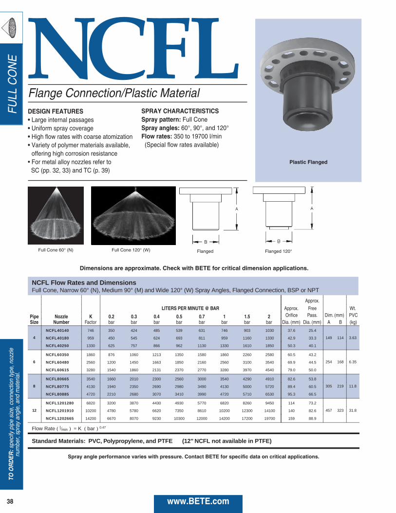
TO ORDER
:specify pipe size, connection type, nozzle
number, spray angle, and material.
38
FULL CONE
www.BETE.com
NCFL
NCFL Flow Rates and Dimensions Full Cone, Narrow 60° (N) , Medium 90° (M) and Wide 120° (W) Spray Angles, Flanged Connection, BSP or NPT
Approx.
LITERS PER MINUTE @ BAR Approx. Free Wt.
Pipe Nozzle K 0.2 0.3 0.4 0.5 0.7 1 1.5 2 Orifice Pass. Dim. (mm) (kg)Size Number Factor bar bar bar bar bar bar bar bar Dia. (mm) Dia. (mm) A B PVC
4
NCFL40140 746 350 424 485 539 631 746 903 1030 37.6 25.4
149 114 3.63 NCFL40180 959 450 545 624 693 811 959 1160 1330 42.9 33.3
NCFL40250 1330 625 757 866 962 1130 1330 1610 1850 50.3 40.1
6
NCFL60350 1860 876 1060 1213 1350 1580 1860 2260 2580 60.5 43.2
254 168 6.35 NCFL60480 2560 1200 1450 1663 1850 2160 2560 3100 3540 69.9 44.5
NCFL60615 3280 1540 1860 2131 2370 2770 3280 3970 4540 79.0 50.0
8
NCFL80665 3540 1660 2010 2300 2560 3000 3540 4290 4910 82.6 53.8
305 219 11.8 NCFL80775 4130 1940 2350 2690 2980 3490 4130 5000 5720 89.4 60.5
NCFL80885 4720 2210 2680 3070 3410 3990 4720 5710 6530 95.3 66.5
12
NCFL1201280 6820 3200 3870 4430 4930 5770 6820 8260 9450 114 73.2
457 323 31.8 NCFL1201910 10200 4780 5780 6620 7350 8610 10200 12300 14100 140 82.6
NCFL1202665 14200 6670 8070 9230 10300 12000 14200 17200 19700 159 88.9
Flow Rate ( l ⁄min ) = K ( bar ) 0.47
Standard Materials: PVC, Polypropylene, and PTFE (12” NCFL not available in PTFE)
M
Flange Connection/Plastic MaterialDESIGN FEATURES• Large internal passages• Uniform spray coverage• High flow rates with coarse atomization• Variety of polymer materials available,offering high corrosion resistance• For metal alloy nozzles refer to SC (pp. 32, 33) and TC (p. 39)
SPRAY CHARACTERISTICSSpray pattern: Full ConeSpray angles: 60°, 90°, and 120°Flow rates: 350 to 19700 l/min(Special flow rates available)
Full Cone 60° (N) Full Cone 120° (W) Flanged Flanged 120°
Plastic Flanged
Dimensions are approximate. Check with BETE for critical dimension applications.
Spray angle performance varies with pressure. Contact BETE for specific data on critical applications.

39www.BETE.com
FULL C
ONE
CALL 413-772-0846
Call for the nam
e of your nearest BETE representative.
TC
TC Flow Rates and DimensionsFull Cone, Narrow 60° (N), Medium 90°(M), and Wide 120°(W) Spray Angles, 6" to 12" Pipe Sizes, BSP or NPT, 12" Flanged
Male orApprox.
Female Available LITERS PER MINUTE @ BAR Free
Pipe Nozzle Spray K 0.1 0.3 0.5 0.7 1 2 3 5 Pass. Dimensions (mm) Wt.Size Number Angles Factor bar bar bar bar bar bar bar bar Dia. (mm) A B C D (kg)
6
TC 532 2820 976 1620 2050 2390 2820 3870 4670 5900
44.5
259 168
11.3TC 588 3110 1080 1790 2260 2640 3110 4280 5160 6520 259 168
TC 827 4380 1520 2520 3180 3710 4380 6020 7250 9180 260 313 168
8
TC 962 5090 1770 2930 3700 4320 5090 7000 8440 10700
52.3
324 219
18.1TC 1120 5930 2060 3410 4310 5030 5930 8150 9820 12400 324 389 219
TC 1260 6670 2310 3830 4850 5660 6670 9170 11100 14000 324 389 219
TC 1480 7830 2720 4500 5690 6650 7830 10800 13000 16400 389 219
Flanged Connection
6
TCFL532 2820 976 1620 2050 2390 2820 3870 4670 5900
44.5
238 168 279
27.2 TCFL588 3110 1080 1790 2260 2640 3110 4280 5160 6520 238 168 279
TCFL827 4380 1520 2520 3180 3710 4380 6020 7250 9180 238 292 168 279
8
TCFL962 5090 1770 2930 3700 4320 5090 7000 8440 10700
52.3
303 219 343
38.6 TCFL1120 5930 2060 3410 4300 5030 5930 8150 9820 12400 303 373 219 343
TCFL1260 6670 2310 3830 4850 5660 6670 9170 11100 14000 303 373 219 343
TCFL1480 7830 2720 4500 5690 6650 7830 10800 13000 16400 303 373 219 343
12
TCFL2070 11000 3800 6300 7960 9300 11000 15100 18200 23000
57.2
432 483
72.6
TCFL2360 12400 4310 7150 9040 10600 12400 17100 20600 26100 432 483
TCFL2510 13300 4610 7630 9660 11300 13300 18300 22000 27800 432 543 323 483
TCFL2660 14100 4880 8090 10200 11900 14100 19400 23300 29500 432 543 323 483
TCFL2960 15700 5430 9000 11400 13300 15700 21500 26000 32800 432 543 323 483
TCFL3250 17200 5960 9880 12500 14600 17200 23700 28500 36100 432 483
Flow Rate ( L ⁄min ) = K ( bar ) 0.46
Standard Materials: 316 Stainless Steel
S
Spray Angles K 0.2 0.3 0.7 1 2 3 5 7 O Dia. (mm) Dia. (mm) A B Metal
3
R l ⁄ ) K ( b
Brass, Carbon Steel, and 316 Stainless Steel
9
60°
90°
90° 120°
90°
120°
120°
60°
90° 120°
90° 120°
120°90°
90° 120°
60°
60°
90°
90° 120°
90°
120°
120°
60°
90° 120°
90° 120°
90° 120°
60°
90°
90° 120°
90° 120°
90° 120°
90°
90°
90°
120°
60°
High Flow Rate/Metal Alloy LineDESIGN FEATURES• One-piece body with integral vanes• Male, female, and flanged connections available
SPRAY CHARACTERISTICS• Extremely high flow ratesSpray pattern: Full ConeSpray angles: 60°, 90°, and 120°Flow rates: 976 to 36100 L/min(Special flow rates available)
Full Cone 90° (M) Male 60°/90° Male 120° 60°/90° Flanged 120° Flanged
Flanged
Dimensions are approximate. Check with BETE for critical dimension applications.
Spray angle performance varies with pressure. Contact BETE for specific data on critical applications.

HOLLOW CONE
TO O
RD
ER:specify pipe size, connection type, nozzle
number, spray angle, and material.
40 www.BETE.com
FemaleMale
WTRight Angle/Hollow ConeDESIGN FEATURES• Conventional design using tangentialwhirl method of atomization• Durable• Use where a circular pattern is requiredor in large area multiple installationswhere there is considerable overlappingof sprays• Male and female connections• Large free passage
SPRAY CHARACTERISTICSSpray pattern: Hollow ConeSpray angles: 70° to 120°Flow rates: 0.125 to 145 l/min
Hollow Cone 80° Hollow Cone 120°
Male Metal
WT Flow Rates and Dimensions Hollow Cone, Medium and Extra Wide Spray Angles, 1/8" to 3/4" Pipe Sizes, BSP or NPT
Male or Female LITERS PER MINUTE @ BAR Approx. (mm)
Pipe Nozzle Spray K 0.3 0.5 0.7 1 2 3 5 7 Inlet Orifice Dimensions for Metal Only (mm) Wt. (g) Size Number Angle Factor bar bar bar bar bar bar bar bar Dia. Dia. A B C D E F G H Metal Plas.
1/8
WT10 70° 110° 0.228 0.125 0.161 0.191 0.228 0.322 0.395 0.510 0.603 1.02 1.17
28.4 22.4 16.0 12.7 22.4 16.0 16.5 12.7 28 14
WT20 70° 115° 0.456 0.250 0.322 0.381 0.456 0.645 0.789 1.02 1.21 1.52 1.52
WT40 70° 0.912 0.499 0.645 0.763 0.912 1.29 1.58 2.04 2.41 2.29 2.29
WT50 115° 1.14 0.624 0.806 0.953 1.14 1.61 1.97 2.55 3.01 2.29 2.29
WT60 70° 115° 1.37 0.749 0.967 1.14 1.37 1.93 2.37 3.06 3.62 2.54 2.79
WT70 115° 1.60 0.874 1.13 1.33 1.60 2.26 2.76 3.57 4.22 2.54 2.79
WT80 120° 1.82 0.999 1.29 1.53 1.82 2.58 3.16 4.08 4.82 2.79 3.05
WT100 70° 115° 2.28 1.25 1.61 1.91 2.28 3.22 3.95 5.10 6.03 3.30 3.30
WT130 120° 2.96 1.62 2.09 2.48 2.96 4.19 5.13 6.62 7.84 3.56 3.56
WT160 70° 3.65 2.00 2.58 3.05 3.65 5.16 6.32 8.15 9.65 3.81 4.06
WT180 120° 4.10 2.25 2.90 3.43 4.10 5.80 7.10 9.17 10.9 4.32 4.06
WT200 70° 4.56 2.50 3.22 3.81 4.56 6.45 7.89 10.2 12.1 4.32 4.83
1/4
WT12 80° 0.273 0.150 0.193 0.229 0.273 0.387 0.474 0.611 0.724 1.02 1.27
33.3 25.4 20.1 16.0 28.4 20.6 20.1 16.0 85 21
WT18 80° 0.410 0.225 0.290 0.343 0.410 0.580 0.710 0.917 1.09 1.52 1.52
WT20 70° 110° 0.456 0.250 0.322 0.381 0.456 0.645 0.789 1.02 1.21 1.52 1.52
WT27 80° 0.615 0.337 0.435 0.515 0.615 0.870 1.07 1.38 1.63 1.78 2.03
WT35 100° 0.798 0.437 0.564 0.667 0.798 1.13 1.38 1.78 2.11 2.03 2.29
WT40 70° 80° 0.912 0.499 0.645 0.763 0.912 1.29 1.58 2.04 2.41 2.03 2.29
WT42 120° 0.957 0.524 0.677 0.801 0.957 1.35 1.66 2.14 2.53 2.03 2.29
WT48 105° 1.09 0.599 0.773 0.915 1.09 1.55 1.89 2.45 2.89 2.29 2.79
Flow Rate ( l ⁄min ) = K √ barbbabar
Standard Materials: Brass, 303 Stainless Steel, and 316 Stainless Steel.
M
B
D
Dimensions are approximate. Check with BETE for critical dimension applications.
Spray angle performance varies with pressure. Contact BETE for specific data on critical applications.

41www.BETE.com
HOLLO
W CONE
CALL 413-772-0846
Call for the nam
e of your nearest BETE representative.
WT Flow Rates and Dimensions Hollow Cone, Medium and Extra Wide Spray Angles, 1/8" to 3/4" Pipe Sizes, BSP or NPT
Male or Female LITERS PER MINUTE @ BAR Approx. (mm)
Pipe Nozzle Spray K 0.3 0.5 0.7 1 2 3 5 7 Inlet Orifice Dimensions for Metal Only (mm) Wt. (g) Size Number Angle Factor bar bar bar bar bar bar bar bar Dia. Dia. A B C D E F G H Metal Plas.
1/4
WT53 80° 1.21 0.662 0.854 1.01 1.21 1.71 2.09 2.70 3.20
33.3 25.4 20.1 16.0 28.4 20.6 20.1 16.0 85 21
WT60 70° 1.37 0.749 0.967 1.14 1.37 1.93 2.37 3.06 3.62
WT68 120° 1.55 0.849 1.10 1.30 1.55 2.19 2.68 3.47 4.10
WT80 120° 1.82 0.999 1.29 1.53 1.82 2.58 3.16 4.08 4.82
WT100 70° 115° 2.28 1.25 1.61 1.91 2.28 3.22 3.95 5.10 6.03
WT130 120° 2.96 1.62 2.09 2.48 2.96 4.19 5.13 6.62 7.84
WT150 120° 3.42 1.87 2.42 2.86 3.42 4.83 5.92 7.64 9.04
WT160 70° 3.65 2.00 2.58 3.05 3.65 5.16 6.32 8.15 9.65
WT180 120° 4.10 2.25 2.90 3.43 4.10 5.80 7.10 9.17 10.9
WT200 70° 120° 4.56 2.50 3.22 3.81 4.56 6.45 7.89 10.19 12.1
WT220 120° 5.01 2.75 3.55 4.19 5.01 7.09 8.68 11.2 13.3
WT240 120° 5.47 3.00 3.87 4.58 5.47 7.73 9.47 12.2 14.5
WT260 80° 5.93 3.25 4.19 4.96 5.93 8.38 10.3 13.2 15.7
WT280 80° 6.38 3.49 4.51 5.34 6.38 9.02 11.1 14.3 16.9
WT300 70° 100° 6.84 3.74 4.83 5.72 6.84 9.67 11.8 15.3 18.1
WT340 80° 7.75 4.24 5.48 6.48 7.75 11.0 13.4 17.3 20.5
WT400 80° 9.12 4.99 6.45 7.63 9.12 12.9 15.8 20.4 24.1
WT480 80° 10.9 5.99 7.73 9.15 10.9 15.5 18.9 24.5 28.9
WT580 80° 13.2 7.24 9.35 11.1 13.2 18.7 22.9 29.6 35.0
WT640 80° 14.6 7.99 10.3 12.2 14.6 20.6 25.3 32.6 38.6
WT680 80° 15.5 8.49 11.0 13.0 15.5 21.9 26.8 34.7 41.0
WT800 80° 18.2 9.99 12.9 15.3 18.2 25.8 31.6 40.8 48.2
3/8
WT100 70° 2.28 1.25 1.61 1.91 2.28 3.22 3.95 5.10 6.03
38.1 28.4 24.6 19.1 34.0 24.6 24.6 19.1 85 21
WT130 120° 2.96 1.62 2.09 2.48 2.96 4.19 5.13 6.62 7.84
WT150 120° 3.42 1.87 2.42 2.86 3.42 4.83 5.92 7.64 9.04
WT160 70° 3.65 2.00 2.58 3.05 3.65 5.16 6.32 8.15 9.65
WT180 120° 4.10 2.25 2.90 3.43 4.10 5.80 7.10 9.17 10.9
WT200 70° 115° 4.56 2.50 3.22 3.81 4.56 6.45 7.89 10.2 12.1
WT220 120° 5.01 2.75 3.55 4.19 5.01 7.09 8.68 11.2 13.3
WT240 125° 5.47 3.00 3.87 4.58 5.47 7.73 9.47 12.2 14.5
WT260 120° 5.93 3.25 4.19 4.96 5.93 8.38 10.3 13.2 15.7
WT270 120° 6.15 3.37 4.35 5.15 6.15 8.70 10.7 13.8 16.3
WT300 70° 115° 6.84 3.74 4.83 5.72 6.84 9.67 11.8 15.3 18.1
WT350 115° 7.98 4.37 5.64 6.67 7.98 11.3 13.8 17.8 21.1
WT400 70° 105° 9.12 4.99 6.45 7.63 9.12 12.9 15.8 20.4 24.1
WT440 105° 10.0 5.49 7.09 8.39 10.0 14.2 17.4 22.4 26.5
WT500 70° 105° 11.4 6.24 8.06 9.53 11.4 16.1 19.7 25.5 30.1
WT560 105° 12.8 6.99 9.02 10.7 12.8 18.0 22.1 28.5 33.8
WT600 70° 13.7 7.49 9.67 11.4 13.7 19.3 23.7 30.6 36.2
WT1000 70° 22.8 12.5 16.1 19.1 22.8 32.2 39.5 51.0 60.3
1/2
WT500 70° 11.4 6.24 8.06 9.53 11.4 16.1 19.7 25.5 30.1
47.5 34.8 31.8 25.4 46.0 33.3 31.8 25.4 276 113
WT600 70° 13.7 7.49 9.67 11.4 13.7 19.3 23.7 30.6 36.2
WT800 70° 18.2 9.99 12.9 15.3 18.2 25.8 31.6 40.8 48.2
WT1000 70° 110° 22.8 12.5 16.1 19.1 22.8 32.2 39.5 51.0 60.3
WT1200 70° 27.3 15.0 19.3 22.9 27.3 38.7 47.4 61.1 72.4
3/4
WT800 70° 18.2 9.99 12.9 15.3 18.2 25.8 31.6 40.8 48.2
57.2 41.1 38.1 31.8 55.6 39.6 38.1 31.8 397 227
WT1000 70° 22.8 12.5 16.1 19.1 22.8 32.2 39.5 51.0 60.3
WT1200 70° 27.3 15.0 19.3 22.9 27.3 38.7 47.4 61.1 72.4
WT1400 80° 31.9 17.5 22.6 26.7 31.9 45.1 55.3 71.3 84.4
WT1600 80° 115° 36.5 20.0 25.8 30.5 36.5 51.6 63.2 81.5 96.5
WT1800 80° 41.0 22.5 29.0 34.3 41.0 58.0 71.0 91.7 109
WT2000 90° 45.6 25.0 32.2 38.1 45.6 64.5 78.9 102 121
WT2200 90° 50.1 27.5 35.5 41.9 50.1 70.9 86.8 112 133
WT2400 90° 54.7 30.0 38.7 45.8 54.7 77.3 94.7 122 145
Flow Rate ( l ⁄min ) = K √ bar
Standard Materials: Brass, 303 Stainless Steel, and 316 Stainless Steel.
2.29 2.79
2.54 2.79
2.54 3.30
3.30 3.30
3.30 3.56
3.81 4.06
4.06 4.32
4.06 4.32
4.57 4.57
4.57 4.83
4.57 5.59
5.08 5.08
5.08 5.08
5.08 5.59
5.08 5.59
5.59 6.10
6.35 7.11
6.35 6.86
6.86 7.62
6.86 7.62
6.86 8.64
6.86 8.64
3.56 3.81
3.56 4.57
4.32 4.57
4.32 4.57
4.32 4.83
4.83 5.08
4.83 5.08
4.83 5.08
4.83 5.84
5.08 5.84
5.08 5.84
6.10 6.35
6.10 6.86
6.60 7.62
6.60 7.11
6.60 7.87
7.87 7.87
8.64 9.65
7.62 7.62
8.38 7.87
9.14 9.14
9.14 11.2
10.2 12.2
9.14 9.65
10.2 11.2
11.2 11.2
11.9 12.2
12.2 13.0
12.7 14.2
13.2 15.0
13.5 16.0
14.0 17.5
Dimensions are approximate. Check with BETE for critical dimension applications.
Spray angle performance varies with pressure. Contact BETE for specific data on critical applications.

HOLLOW CONE
TO O
RD
ER:specify pipe size, connection type, nozzle
number, spray angle, and material.
42 www.BETE.com
WTXExtended Life/Hollow ConeDESIGN FEATURES• Tangential whirl• Oversized body for extended life• Male and female connections• Large free passage
SPRAY CHARACTERISTICSSpray pattern: Hollow ConeSpray angles: 70° to 120°Flow rates: 0.13 to 145 l/min
Hollow Cone 80° Hollow Cone 120° Male Female
Metal
WTX Flow Rates and Dimensions Hollow Cone, Medium and Extra Wide Spray Angles, 1/8" to 3/4" Pipe Sizes, BSP or NPT
Male or Female LITERS PER MINUTE @ BAR Approx. (mm)
Pipe Nozzle Spray K 0.3 0.5 0.7 1 2 3 5 7 Inlet Orifice Dimensions for Metal Only (mm) Wt. (g) Size Number Angle Factor bar bar bar bar bar bar bar bar Dia. Dia. A B C D E F G H Metal
1/8
WTX10 70° 110° 0.228 0.125 0.161 0.191 0.228 0.322 0.395 0.510 0.603 1.02 1.17
28.4 22.4 22.4 19.1 25.4 19.1 22.4 19.1 32
WTX20 70° 115° 0.456 0.250 0.322 0.381 0.456 0.645 0.789 1.02 1.21 1.52 1.52
WTX40 70° 0.912 0.499 0.645 0.763 0.912 1.29 1.58 2.04 2.41 2.29 2.29
WTX50 115° 1.14 0.624 0.806 0.953 1.14 1.61 1.97 2.55 3.01 2.29 2.29
WTX60 70° 115° 1.37 0.749 0.967 1.14 1.37 1.93 2.37 3.06 3.62 2.54 2.79
WTX70 115° 1.60 0.874 1.13 1.33 1.60 2.26 2.76 3.57 4.22 2.54 2.79
WTX80 120° 1.82 0.999 1.29 1.53 1.82 2.58 3.16 4.08 4.82 2.79 3.05
WTX100 70° 115° 2.28 1.25 1.61 1.91 2.28 3.22 3.95 5.10 6.03 3.30 3.30
WTX130 120° 2.96 1.62 2.09 2.48 2.96 4.19 5.13 6.62 7.84 3.56 3.56
WTX160 70° 3.65 2.00 2.58 3.05 3.65 5.16 6.32 8.15 9.65 3.81 4.06
WTX180 120° 4.10 2.25 2.90 3.43 4.10 5.80 7.10 9.17 10.9 4.32 4.06
WTX200 70° 4.56 2.50 3.22 3.81 4.56 6.45 7.89 10.2 12.1 4.32 4.83
1/4
WTX12 80° 0.273 0.150 0.193 0.229 0.273 0.387 0.474 0.611 0.724 1.02 1.27
33.3 25.4 22.4 19.1 33.3 25.4 22.4 19.1 74
WTX18 80° 0.410 0.225 0.290 0.343 0.410 0.580 0.710 0.917 1.09 1.52 1.52
WTX20 70° 110° 0.456 0.250 0.322 0.381 0.456 0.645 0.789 1.02 1.21 1.52 1.52
WTX27 80° 0.615 0.337 0.435 0.515 0.615 0.870 1.07 1.38 1.63 1.78 2.03
WTX35 100° 0.798 0.437 0.564 0.667 0.798 1.13 1.38 1.78 2.11 2.03 2.29
WTX40 70° 80° 0.912 0.499 0.645 0.763 0.912 1.29 1.58 2.04 2.41 2.03 2.29
WTX42 120° 0.957 0.524 0.677 0.801 0.957 1.35 1.66 2.14 2.53 2.03 2.29
WTX48 105° 1.09 0.599 0.773 0.915 1.09 1.55 1.89 2.45 2.89 2.29 2.79
Flow Rate ( l ⁄min ) = K √ bar
Standard Materials: Brass, 303 Stainless Steel, and 316 Stainless Steel
M
B
D
Dimensions are approximate. Check with BETE for critical dimension applications.
Spray angle performance varies with pressure. Contact BETE for specific data on critical applications.
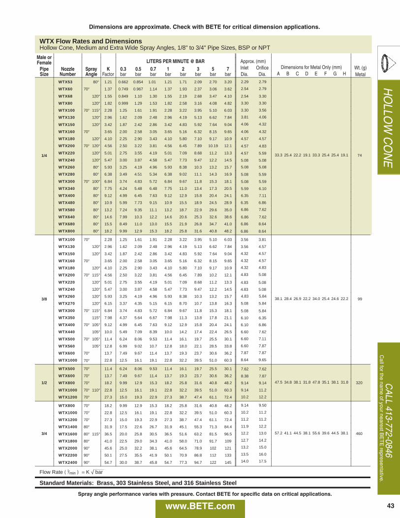
43www.BETE.com
HOLLO
W CONE
CALL 413-772-0846
Call for the nam
e of your nearest BETE representative.
WTX Flow Rates and Dimensions Hollow Cone, Medium and Extra Wide Spray Angles, 1/8" to 3/4" Pipe Sizes, BSP or NPT
Male or Female LITERS PER MINUTE @ BAR Approx. (mm)
Pipe Nozzle Spray K 0.3 0.5 0.7 1 2 3 5 7 Inlet Orifice Dimensions for Metal Only (mm) Wt. (g) Size Number Angle Factor bar bar bar bar bar bar bar bar Dia. Dia. A B C D E F G H Metal
1/4
WTX53 80° 1.21 0.662 0.854 1.01 1.21 1.71 2.09 2.70 3.20
33.3 25.4 22.2 19.1 33.3 25.4 25.4 19.1 74
WTX60 70° 1.37 0.749 0.967 1.14 1.37 1.93 2.37 3.06 3.62
WTX68 120° 1.55 0.849 1.10 1.30 1.55 2.19 2.68 3.47 4.10
WTX80 120° 1.82 0.999 1.29 1.53 1.82 2.58 3.16 4.08 4.82
WTX100 70° 115° 2.28 1.25 1.61 1.91 2.28 3.22 3.95 5.10 6.03
WTX130 120° 2.96 1.62 2.09 2.48 2.96 4.19 5.13 6.62 7.84
WTX150 120° 3.42 1.87 2.42 2.86 3.42 4.83 5.92 7.64 9.04
WTX160 70° 3.65 2.00 2.58 3.05 3.65 5.16 6.32 8.15 9.65
WTX180 120° 4.10 2.25 2.90 3.43 4.10 5.80 7.10 9.17 10.9
WTX200 70° 120° 4.56 2.50 3.22 3.81 4.56 6.45 7.89 10.19 12.1
WTX220 120° 5.01 2.75 3.55 4.19 5.01 7.09 8.68 11.2 13.3
WTX240 120° 5.47 3.00 3.87 4.58 5.47 7.73 9.47 12.2 14.5
WTX260 80° 5.93 3.25 4.19 4.96 5.93 8.38 10.3 13.2 15.7
WTX280 80° 6.38 3.49 4.51 5.34 6.38 9.02 11.1 14.3 16.9
WTX300 70° 100° 6.84 3.74 4.83 5.72 6.84 9.67 11.8 15.3 18.1
WTX340 80° 7.75 4.24 5.48 6.48 7.75 11.0 13.4 17.3 20.5
WTX400 80° 9.12 4.99 6.45 7.63 9.12 12.9 15.8 20.4 24.1
WTX480 80° 10.9 5.99 7.73 9.15 10.9 15.5 18.9 24.5 28.9
WTX580 80° 13.2 7.24 9.35 11.1 13.2 18.7 22.9 29.6 35.0
WTX640 80° 14.6 7.99 10.3 12.2 14.6 20.6 25.3 32.6 38.6
WTX680 80° 15.5 8.49 11.0 13.0 15.5 21.9 26.8 34.7 41.0
WTX800 80° 18.2 9.99 12.9 15.3 18.2 25.8 31.6 40.8 48.2
3/8
WTX100 70° 2.28 1.25 1.61 1.91 2.28 3.22 3.95 5.10 6.03
38.1 28.4 26.9 22.2 34.0 25.4 24.6 22.2 99
WTX130 120° 2.96 1.62 2.09 2.48 2.96 4.19 5.13 6.62 7.84
WTX150 120° 3.42 1.87 2.42 2.86 3.42 4.83 5.92 7.64 9.04
WTX160 70° 3.65 2.00 2.58 3.05 3.65 5.16 6.32 8.15 9.65
WTX180 120° 4.10 2.25 2.90 3.43 4.10 5.80 7.10 9.17 10.9
WTX200 70° 115° 4.56 2.50 3.22 3.81 4.56 6.45 7.89 10.2 12.1
WTX220 120° 5.01 2.75 3.55 4.19 5.01 7.09 8.68 11.2 13.3
WTX240 120° 5.47 3.00 3.87 4.58 5.47 7.73 9.47 12.2 14.5
WTX260 120° 5.93 3.25 4.19 4.96 5.93 8.38 10.3 13.2 15.7
WTX270 120° 6.15 3.37 4.35 5.15 6.15 8.70 10.7 13.8 16.3
WTX300 70° 115° 6.84 3.74 4.83 5.72 6.84 9.67 11.8 15.3 18.1
WTX350 115° 7.98 4.37 5.64 6.67 7.98 11.3 13.8 17.8 21.1
WTX400 70° 105° 9.12 4.99 6.45 7.63 9.12 12.9 15.8 20.4 24.1
WTX440 105° 10.0 5.49 7.09 8.39 10.0 14.2 17.4 22.4 26.5
WTX500 70° 105° 11.4 6.24 8.06 9.53 11.4 16.1 19.7 25.5 30.1
WTX560 105° 12.8 6.99 9.02 10.7 12.8 18.0 22.1 28.5 33.8
WTX600 70° 13.7 7.49 9.67 11.4 13.7 19.3 23.7 30.6 36.2
WTX1000 70° 22.8 12.5 16.1 19.1 22.8 32.2 39.5 51.0 60.3
1/2
WTX500 70° 11.4 6.24 8.06 9.53 11.4 16.1 19.7 25.5 30.1
47.5 34.8 38.1 31.8 47.8 35.1 38.1 31.8 320
WTX600 70° 13.7 7.49 9.67 11.4 13.7 19.3 23.7 30.6 36.2
WTX800 70° 18.2 9.99 12.9 15.3 18.2 25.8 31.6 40.8 48.2
WTX1000 70° 110° 22.8 12.5 16.1 19.1 22.8 32.2 39.5 51.0 60.3
WTX1200 70° 27.3 15.0 19.3 22.9 27.3 38.7 47.4 61.1 72.4
3/4
WTX800 70° 18.2 9.99 12.9 15.3 18.2 25.8 31.6 40.8 48.2
57.2 41.1 44.5 38.1 55.6 39.6 44.5 38.1 460
WTX1000 70° 22.8 12.5 16.1 19.1 22.8 32.2 39.5 51.0 60.3
WTX1200 70° 27.3 15.0 19.3 22.9 27.3 38.7 47.4 61.1 72.4
WTX1400 80° 31.9 17.5 22.6 26.7 31.9 45.1 55.3 71.3 84.4
WTX1600 80° 115° 36.5 20.0 25.8 30.5 36.5 51.6 63.2 81.5 96.5
WTX1800 80° 41.0 22.5 29.0 34.3 41.0 58.0 71.0 91.7 109
WTX2000 90° 45.6 25.0 32.2 38.1 45.6 64.5 78.9 102 121
WTX2200 90° 50.1 27.5 35.5 41.9 50.1 70.9 86.8 112 133
WTX2400 90° 54.7 30.0 38.7 45.8 54.7 77.3 94.7 122 145
Flow Rate ( l ⁄min ) = K √ bar
Standard Materials: Brass, 303 Stainless Steel, and 316 Stainless Steel
2.29 2.79
2.54 2.79
2.54 3.30
3.30 3.30
3.30 3.56
3.81 4.06
4.06 4.32
4.06 4.32
4.57 4.57
4.57 4.83
4.57 5.59
5.08 5.08
5.08 5.08
5.08 5.59
5.08 5.59
5.59 6.10
6.35 7.11
6.35 6.86
6.86 7.62
6.86 7.62
6.86 8.64
6.86 8.64
3.56 3.81
3.56 4.57
4.32 4.57
4.32 4.57
4.32 4.83
4.83 5.08
4.83 5.08
4.83 5.08
4.83 5.84
5.08 5.84
5.08 5.84
6.10 6.35
6.10 6.86
6.60 7.62
6.60 7.11
6.60 7.87
7.87 7.87
8.64 9.65
7.62 7.62
8.38 7.87
9.14 9.14
9.14 11.2
10.2 12.2
9.14 9.50
10.2 11.2
11.2 11.2
11.9 12.2
12.2 13.0
12.7 14.2
13.2 15.0
13.5 16.0
14.0 17.5
Dimensions are approximate. Check with BETE for critical dimension applications.
Spray angle performance varies with pressure. Contact BETE for specific data on critical applications.

HOLLOW CONE
TO O
RD
ER:specify pipe size, connection type, nozzle
number, spray angle, and material.
44 www.BETE.com
CW
K 0.7 1 2 3 5 10 15 20 O Metal Only (mm) Wt. (g) S Dia. (mm) A B C D M P
R l ) = K b
Brass, 303 Stainless Steel, 316 Stainless Steel, PVC, Polypropylene, and PTFE (1/8" PTFE andP
CW Flow Rates and Dimensions Hollow Cone, 80° and 120° Spray Angles, 1/8" to 3/8" Pipe Sizes, BSP or NPT
Male or Female LITERS PER MINUTE @ BAR Approx. Wt.
Pipe Nozzle K 0.5 0.7 1 2 3 5 10 15 Orifice Dimensions (mm) (g) Size Number Factor bar bar bar bar bar bar bar bar Dia.(mm) A B C Metal 1/8 or CW25-H 0.587 0.424 0.497 0.587 0.814 0.984 1.25 1.73 2.10 1.14
71 1/4 CW50-H 1.17 0.848 0.993 1.17 1.63 1.97 2.50 3.47 4.19 1.37
or CW75-H 1.76 1.27 1.49 1.76 2.44 2.95 3.75 5.20 6.29 1.60
3/8 CW100-H 2.35 1.70 1.99 2.35 3.25 3.94 5.01 6.93 8.39 2.18
Flow Rate ( l ⁄min ) = K ( bar )0.47
Standard Materials: Brass, 303 Stainless Steel, and 316 Stainless Steel
S
N
D
17.5 20.6 17.3 52.3
17.5 20.6 20.6 52.3
1/8-1/4
3/8
Male or Female
Pipe Size
Low FlowDESIGN FEATURES• Standard 3-piece construction• Optional 50- or 100-mesh strainer(refer to page 119 for additional information)• Protective cover available• Male and female connections• Interchangeable spray tips
SPRAY CHARACTERISTICSSpray patterns: Hollow Cone (H)For Full Cone, see page 28Spray angles: 80° and 120°Flow rates: 0.424 to 8.39 l/min
Full Cone 80° (F) Hollow Cone 80° (H)
Male Metal
Male Female
Dimensions are approximate. Check with BETE for critical dimension applications.
Spray angle performance varies with pressure. Contact BETE for specific data on critical applications.

45www.BETE.com
HOLLO
W CONE
CALL 413-772-0846
Call for the nam
e of your nearest BETE representative.
Available Approx. (mm)
Male Spray LITERS PER MINUTE @ BAR Free Dim. (mm) for Wt. (g)
Pipe Nozzle Angles K 0.5 0.7 1 2 3 5 10 20 Orif. Pass. Metal Only* 180°Size Number 50° 60° 90° 120° 180° Factor bar bar bar bar bar bar bar bar Dia. Dia. A B C Metal Plas.
1/4 TF6 50° 60° 90° 120° 3.19 2.26 2.67 3.19 4.5 5.5 7.1 10.1 14.3 2.38 2.38 42.9 14.3
35 21TF8 50° 60° 90° 120° 180° 5.93 4.19 4.96 5.93 8.4 10.3 13.2 18.7 26.5 3.18 3.18 47.6 14.3 47.6
TF10 50° 60° 90° 120° 180° 9.12 6.45 7.63 9.12 12.9 15.8 20.4 28.8 40.8 3.97 3.18 47.6 14.3 47.6
3/8
TF12 50° 60° 90° 120° 180° 13.7 9.7 11.4 13.7 19.3 23.7 30.6 43.2 61.1 4.76 3.18
47.6 17.51 47.6 50 21TF14 50° 60° 90° 120° 180° 18.5 13.1 15.4 18.5 26.1 32.0 41.3 58.4 82.6 5.56 3.18
TF16 50° 60° 90° 120° 180° 24.2 17.1 20.2 24.2 34.2 41.8 54.0 76.4 108 6.35 3.18
TF20 50° 60° 90° 120° 180° 37.6 26.6 31.5 37.6 53.2 65.1 84.1 119 168 7.94 3.18
1/2 TF24 50° 60° 90° 120° 180° 54.9 38.8 46.0 54.9 77.7 95.1 123 174 246 9.53 4.76 63.5 22.2 60.5 85 25TF28 50° 60° 90° 120° 180° 75.2 53.2 62.9 75.2 106 130 168 238 336 11.1 4.76
3/4 TF32 50° 60° 90° 120° 180° 95.7 67.7 80.1 95.7 135 166 214 303 428 12.7 4.76 69.9 28.6 76.2 85 28
1 TF40 60° 90° 120° 180° 153 108 128 153 216 264 341 483 683 15.9 6.35 34.9 92.2 425 85TF48 60° 90° 120° 180° 217 153 181 216 306 375 484 685 968 19.1 6.35
1 1/2 TF56 60° 90° 120° 180° 294 208 246 294 416 509 657 930 1320 22.2 7.94
50.8 111 851 170TF64 60° 90° 120° 180° 385 272 322 385 545 667 861 1220 1720 25.4 7.94
TF72 60° 90° 120° 180° 438 309 366 438 619 758 978 1380 1960 28.6 7.94
2 TF88 60° 90° 120° 180° 638 451 534 638 902 1110 1430 2020 2850 34.9 11.1 143 63.5 127 1300 227TF96 60° 90° 120° 180° 806 570 674 806 1140 1400 1800 2550 3600 38.1 11.1 176 63.5 127 1530 255
3 TF112 60° 90° 120° 1170 825 976 1170 1650 2020 2610 3690 5220 44.5 14.3 219 88.9TF128 60° 90° 120° 1550 1090 1290 1550 2190 2680 3460 4891 6920 50.8 14.3
4 TF160 60° 90° 120° 2390 1690 2000 2390 3380 4140 5350 7570 10700 63.5 15.9 257 114
Flow Rate ( L⁄min ) = K √ bar *Dimensions are for bar stock, cast sizes may vary. 1 25.4 mm for 180°
Standard Materials: Brass, 316 Stainless Steel, PVC, Polypropylene, and PTFE (Poly. not available for TF6 - TF10)
111
92.1
PTFE not recommended at pressuresabove red line
Metal ONLY at pressuresabove green line
TF Hollow Cone Flow Rates and Dimensions Hollow Cone, 50° (N) , 60° (V) , 90° (M), 120° (W), and 180° (XW) Spray Angles, 1/4" to 4" Pipe Sizes, BSP or NPT
180°
Hollow Cone 50° (N) Hollow Cone 120° (W) 50°, 60°, 90°, 120° 180°Hollow Cone 180° (XW)
TFWide Range of Flows and AnglesDESIGN FEATURES• The original spiral nozzle invented by BETE and continuously improved!
• High energy efficiency• One-piece/no internal parts• Clog-resistant performance• High discharge velocity• Male connection standard; female connection available by special order
SPRAY CHARACTERISTICS• Wide range of flow rates and spray angles• Fine atomizationSpray patterns: Hollow ConeFor Full Cone, see page 20Spray angles: 50° to 180°Flow rates: 2.26 to 10700 L/min(Higher flow rates available)
180° Metal
Dimensions are approximate. Check with BETE for critical dimension applications
Spray angle performance varies with pressure. Contact BETE for specific data on critical applications.
TF8 and TF 24 150° are Factory Mutual approved. Contact BETE for more information.

LITERS PER MINUTE @ BAR Approx. Approx. AssemblyPipe Nozzle K 0.3 0.5 0.7 1 2 3 5 7 10 15 20 30 Orifice Dim. (mm) Wt.Size Number Factor bar bar bar bar bar bar bar bar bar bar bar bar Dia. (mm) Hex Length (g)
1/8” EZTF6 3.19 1.75 2.26 2.67 3.19 4.51 5.53 7.13 8.44 10.1 12.4 14.3 17.5 2.38 1/8” 22.4 41.4 62TO EZTF8 5.93 3.25 4.19 4.96 5.93 8.38 10.3 13.2 15.7 18.7 22.9 26.5 32.5 3.181/2” EZTF10 9.12 4.99 6.45 7.63 9.12 12.9 15.8 20.4 24.1 28.8 35.3 40.8 49.9 3.97 1/4” 22.4 44.5 62 EZTF12 13.7 7.49 9.7 11.4 13.7 19.3 23.7 30.6 36.2 43.2 53.0 61.1 74.9 4.76
1/4” EZTF14 18.5 10.1 13.1 15.4 18.5 26.1 32.0 41.3 48.8 58.4 71.5 82.6 101 5.56 3/8” 22.4 46.0 74TO EZTF16 24.2 13.2 17.1 20.2 24.2 34.2 41.8 54.0 63.9 76.4 93.6 108 132 6.351/2” EZTF20 37.6 20.6 26.6 31.5 37.6 53.2 65.1 84.1 99.5 119 146 168 206 7.94 1/2” 22.4 47.5 82
Flow Rate (l/min) = K Ö bar TF20 not available with 1/8” base
Standard Materials: Brass, Viton and Buna-N gaskets standard. 316 Stainless Steel available upon request.
HOLLOW CONE
TO O
RD
ER:specify pipe size, connection type, nozzle
number, spray angle, and material.
46 www.BETE.com
EZTF WTDESIGN FEATURES• Nozzles can be changed in secondswithout tools
• Three part nozzle, base, gasket andinterchangeable tip
• Exclusive ramped engagement forefficient automatic alignment
• Threaded adapters will accommodateother standard BETE nozzles. Shut-offplugs are also available
SPRAY CHARACTERISTICS• Available in six standard tips: EZTF;EZWL; EZWT; EZFF; EZNF; EZSPN
More EZ tips:Full Cone: page 30Flat Fan: pages 66 and 67
Flow rates: 0.13 to 206 l/minSpray Angles:EZTF: 60°, 90°, 120°, and 180° EZWT: 70° and 110°
EZ Change Quick Connection System
EZTF
120° Hollow Cone
Dimensions are approximate. Check with BETE for critical dimension applications.
Spray angle performance varies with pressure. Contact BETE for specific data on critical applications.
EZTF Flow Rates and DimensionsHollow Cone Spiral 60° ( V), 90° ( M), 120° ( W), 150°, 170° or 180° (XW) Spray Angle 1/8” to 1/2” BSP or NPT

LITERS PER MINUTE @ BAR Approx.
Assembly Pipe Nozzle K 0.3 0.5 0.7 1 2 3 5 7 10 15 20 30 Orifice Dim. (mm) Wt.Size Number Factor bar bar bar bar bar bar bar bar bar bar bar bar Dia. (mm) Hex Length (g)
EZWT10 0.228 0.13 0.16 0.19 0.23 0.32 0.40 0.51 0.60 0.72 0.88 1.02 1.25 0.794 EZWT12 0.273 0.15 0.19 0.23 0.27 0.39 0.47 0.61 0.72 0.87 1.06 1.22 1.50 0.794 EZWT18 0.410 0.23 0.29 0.34 0.42 0.58 0.71 0.92 1.09 1.30 1.59 1.83 2.25 1.19 EZWT20 0.456 0.25 0.32 0.38 0.46 0.65 0.79 1.02 1.21 1.44 1.77 2.04 2.50 1.59 1/8” 22.4 41.4 62 EZWT27 0.615 0.34 0.44 0.52 0.62 0.87 1.07 1.38 1.63 1.95 2.38 2.75 3.37 1.19 EZWT35 0.798 0.44 0.56 0.67 0.80 1.13 1.38 1.78 2.11 2.52 3.09 3.57 4.37 1.591/8” EZWT40 0.912 0.50 0.65 0.76 0.91 1.29 1.58 2.04 2.41 2.88 3.53 4.08 4.99 1.98 EZWT42 0.957 0.52 0.68 0.80 0.96 1.35 1.66 2.14 2.53 3.03 3.71 4.28 5.24 1.59 EZWT48 1.09 0.60 0.77 0.92 1.09 1.55 1.89 2.45 2.89 3.46 4.24 4.89 5.99 1.59 EZWT50 1.14 0.62 0.81 0.95 1.14 1.61 1.97 2.55 3.01 3.60 4.41 5.10 6.24 1.98 EZWT53 1.21 0.66 0.85 1.01 1.21 1.71 2.09 2.70 3.20 3.82 4.68 5.40 6.62 1.98 1/4” 22.4 44.5 62 EZWT60 1.37 0.75 0.97 1.14 1.37 1.93 2.37 3.06 3.62 4.32 5.30 6.11 7.49 2.38 EZWT68 1.55 0.85 1.10 1.30 1.55 2.19 2.68 3.47 4.10 4.90 6.00 6.93 8.49 1.98TO EZWT70 1.60 0.87 1.13 1.33 1.60 2.26 2.76 3.57 4.22 5.04 6.18 7.13 8.74 2.38 EZWT80 1.82 1.00 1.29 1.53 1.82 2.58 3.16 4.08 4.82 5.77 7.06 8.15 9.99 1.98 EZWT100 2.28 1.25 1.61 1.91 2.28 3.22 3.95 5.10 6.03 7.21 8.83 10.2 12.5 3.18 EZWT130 2.96 1.62 2.09 2.48 2.96 4.19 5.13 6.62 7.84 9.37 11.5 13.2 16.2 3.18 3/8” 22.4 46.0 74 EZWT150 3.42 1.87 2.42 2.86 3.42 4.83 5.92 7.64 9.04 10.8 13.2 15.3 18.7 3.57 EZWT160 3.65 2.00 2.58 3.05 3.65 5.16 6.32 8.15 9.65 11.5 14.1 16.3 20.0 3.97 EZWT180 4.10 2.25 2.90 3.43 4.10 5.80 7.10 9.17 10.9 13.0 15.9 18.3 22.5 3.971/2” EZWT200 4.56 2.50 3.22 3.81 4.56 6.45 7.89 10.2 12.1 14.4 17.7 20.4 25.0 4.37 EZWT220 5.01 2.75 3.55 4.19 5.01 7.09 8.68 11.2 13.3 15.9 19.4 22.4 27.5 3.97 EZWT240 5.47 3.00 3.87 4.58 5.47 7.73 9.47 12.2 14.5 17.3 21.2 24.5 30.0 4.76 EZWT260 5.93 3.25 4.19 4.96 5.93 8.38 10.3 13.2 15.7 18.7 22.9 26.5 32.5 5.16 1/2” 22.4 47.5 82 EZWT270 6.15 3.37 4.35 5.15 6.15 8.70 10.7 13.8 16.3 19.5 23.8 27.5 33.7 5.16 EZWT280 6.38 3.49 4.51 5.34 6.38 9.02 11.1 14.3 16.9 20.2 24.7 28.5 34.9 5.56 EZWT300 6.84 3.74 4.83 5.72 6.84 9.67 11.8 15.3 18.1 21.6 26.5 30.6 37.4 5.56 EZWT340 7.75 4.24 5.48 6.48 7.75 11.0 13.4 17.3 20.5 24.5 30.0 34.7 42.4 5.56 EZWT350 7.98 4.37 5.64 6.67 7.98 11.3 13.8 17.8 21.1 25.2 30.9 35.7 43.7 5.95 EZWT400 9.12 4.99 6.45 7.63 9.12 12.9 15.8 20.4 24.1 28.8 35.3 40.8 49.9 7.14
Flow Rate (l/min) = K Ö barStandard Materials: 303 Stainless Steel, 316 Stainless Steel, Brass, Viton gaskets standard.
47www.BETE.com
HOLLO
W CONE
CALL 413-772-0846
Call for the nam
e of your nearest BETE representative.
NPT / R NPT / R NPT / R NPT / R
FNPT / RPFNPT / RPFNPT / RPFNPT / RP
25.4mm 32.5mm
42.4mm
31.0mm
30.5mm 28.7mm 22.6mm
26.4mm29.5mm
26.4mm29.5mm
31.0mm36.8mm
Dimensions are approximate. Check with BETE for critical dimension applications.
EZWT Flow Rates and DimensionsHollow Cone, Narrow (70°) and Wide (110°) Spray Angles 1/8” to 1/2” BSP or NPT

LITERS PER MINUTE @ BAR
Available Approx.Nozzle Spray K 0.5 0.7 1 2 3 5 7 10 Pipe Body Dim. (mm) Wt.Number Angle Factor bar bar bar bar bar bar bar bar Size Color A B (g)SF15HC 90° 3.416 2.42 2.86 3.42 4.83 5.92 7.64 9.04 10.8 1” blue 83.8 43.2 62.4SF58HC 50° 13.22 9.35 11.1 13.2 18.7 22.9 29.6 35.0 41.8 1-1/4” red 86.4 48.3 62.4SF100HC 65° 22.79 16.1 19.1 22.8 32.2 39.5 51.0 60.3 72.1 1-1/2” purple 91.4 50.8 62.4 2” green 94.0 55.9 62.4
Flow Rate (l/min) = K Ö bar
Standard Materials: Polypropylene, 302 Stainless Steel clamp, EPDM seal.Optional Materials: 303 Stainless Steel clamp, Viton seal.
HOLLOW CONE
TO O
RD
ER:specify pipe size, connection type, nozzle
number, spray angle, and material.
48 www.BETE.com
SFCLAMP-ON ADAPTER• Available for 1”, 1-1/4”, 1-1/2” and 2” pipe.• Available with 1/8”, 1/4”, 3/8”, 1/2” NPTfemale threads; or 1/8” BSP female threads
• Available with single or double clamp.• TO ORDER ADAPTER Specify: PipeSize, thread size, thread type, numberof clamps, materials.
Double Clamp Adapter with Spiral Nozzle
DESIGN FEATURES• Nozzles can be quickly changed and aligned by hand without tools
• Clamp-on adapter fits any style nozzle• Quick set-up system features special“Snap-in” tips
• Polypropylene, resistant to most acidsand alkalies
• Double clamp base or adapteravailable for higher pressure operation
SPRAY CHARACTERISTICS• Quick Set-up System can be providedwith fan, hollow or full cone spray tips
• Full 45° alignment of spray without toolsMore SF Nozzle Systems:Full Cone: page 31Flat Fan: page 68Flow rates: 2.42 - 72.1 l/minSpray angles:Fan: 40°, 50°, 65°, 80°, 95°Hollow Cone: 50°, 65°, 90°Full Cone: 35°, 65°, 80°
Snap Release Nozzle System
Dimensions are approximate. Check with BETE for critical dimension applications.
A
B
2.1”45°
Double-Clamp Adapter
Single-Clamp Base
Retainer Cap“SNAP-IN”Threaded Swivel Ball
Available with 1/8”, 1/4”, 3/8”, 1/2”NPT or BSPFemale threads
Single-Clamp Adapter
“SNAP-IN”Hollow Cone Nozzle Tip
SF Flow Rates and DimensionsSF Hollow Cone 50°, 65° and 90° Spray Angles 1”, 1-1/4”, 1-1/2” and 2”
NOTE: Drill 16.7mm (21/32”) hole in pipe to install SF.
NOTE: Maximum recommended pressures for SF assemblies: With single clamp 5 bar for 1” pipe; 3.5 bar for 1-1/4” and 1-1/2” pipe; and 2bar for 2” pipe; with double clamp up to 10 bar.

49www.BETE.com
HOLLO
W CONE
CALL 413-772-0846
Call for the nam
e of your nearest BETE representative.
Dia. (mm) Dia. (mm) A B C D
2
N
R L ) = K b 0
PVC, Polypropylene, and PTFE. S
NCJ Flow Rates and Dimensions Hollow Cone, 15°, 20°, and 30° Spray Angles, 3/4" to 6" Pipe Sizes, BSP or NPT
Male or Female LITERS PER MINUTE @ BAR Approx. Dimensions for Wt.
Pipe Nozzle K 0.5 0.7 1 1.5 2 3 5 7 Orifice Metal Only (mm) (kg)Size Number Factor bar bar bar bar bar bar bar bar Dia. (mm) A B C Metal
3/4 NC 0706J 32.0 23.1 27.0 32.0 38.7 44.3 53.6 68.1 79.8 7.52 82.6 34.9 28.4 0.04 0.34
1 NC 1012J 64.0 46.2 54.1 64.0 77.4 88.6 107 136 160 10.3 88.9 44.5 35.1 0.06 0.45
1 1/4 NC 1218J 95.9 69.3 81.1 95.9 116 133 161 204 239 12.3 102 50.8 44.5 0.11 0.57
1 1/2 NC 1526J 139 100 117 139 168 192 232 295 346 15.1 127 63.5 50.8 0.20 1.02
2 NC 2048J 256 185 216 256 310 354 429 545 638 20.2 152 76.2 63.5 0.37 1.13
2 1/2 NC 2572J 384 277 325 384 464 532 643 818 958 24.6 178 82.6 76.2 0.62 2.61
3 NC 30105J 560 404 473 560 677 775 938 1190 1400 29.5 203 97.5 88.9 0.85 2.84
4 NC 40190J 1010 731 856 1010 1230 1400 1700 2160 2530 40.5 251 127 114 2.04 6.80
6 NC 60350J 1860 1380 1580 1860 2260 2580 3130 3980 4660 54.0 343 181 168 2.78 15.9
Flow Rate ( L⁄min ) = K ( bar ) 0.47
Standard Materials: Brass, 316 Stainless Steel, PVC, Polypropylene, and PTFE
W
D
82.6
88.9
102
127
152
194
203
278
381
PVC
Hollow Cone/Narrow Angle Injector
DESIGN FEATURES• Narrow spray angles • High velocity• Male and female connections• Flanged connections available• Available in plastic and metal alloys
SPRAY CHARACTERISTICS• Spray is coarse and extremely hard-drivingSpray pattern: Hollow ConeSpray angles: 15°, 20°, and 30°Flow rates: 23.1 to 4660 L/min(Special flow rates available)
Hollow Cone 20° Hollow Cone 30° MaleHollow Cone 15° Female
Metal
Dimensions are approximate. Check with BETE for critical dimension applications.
NCJ
NOTE for PTFE nozzles: if operating temperature is to exceed 150 °C or the operating pressure is to exceed the valueslisted in the table above, please contact BETE Applications Engineering for assistance.
Spray angle performance varies with pressure. Contact BETE for specific data on critical applications.

HOLLOW CONE
TO O
RD
ER:specify pipe size, connection type, nozzle
number, spray angle, and material.
50 www.BETE.com
TH
TH Flow Rates and DimensionsHollow Cone, Narrow to Medium Spray Angles, 1" to 3" Pipe Sizes, BSP or NPT
FemaleSpray Ang. LITERS PER MINUTE @ BAR Approx. Free
Pipe Nozzle 0.3 1 3 K 0.2 0.3 0.5 0.7 1 1.5 2 3 Orifice Pass.Dimensions (mm)
Wt.Size Number bar bar bar Factor bar bar bar bar bar bar bar bar Dia. (mm) Dia. (mm) A B C D (kg)
1
THF1508 54° 54° 54° 34.2 15.3 18.7 24.2 28.6 34.2 41.9 48.3 59.2 8.73 8.73
58.7 79.5 63.3 39.4 0.47
THF1808 56° 56° 56° 41.0 18.3 22.5 29.0 34.3 41.0 50.2 58.0 71.0 9.53 9.53
THF2308 63° 66° 66° 52.4 23.4 28.7 37.1 43.9 52.4 64.2 74.1 90.8 11.1 11.1
THF2708 66° 70° 70° 61.5 27.5 33.7 43.5 51.5 61.5 75.4 87.0 107 11.9 11.9
THF3208 68° 72° 71° 72.9 32.6 39.9 51.6 61.0 72.9 89.3 103 126 13.9 13.9
THF 3808 68° 72° 71° 86.6 38.7 47.4 61.2 72.5 86.6 106 122 150 15.2 15.2
1 1/4
THF3210 66° 66° 66° 72.9 32.6 39.9 51.6 61.0 72.9 89.3 103 126 13.9 13.9
74.2 99.3 75.4 46.7 0.75
THF3810 68° 70° 70° 86.6 38.7 47.4 61.2 72.5 86.6 106 122 150 15.9 15.9
THF4110 73° 74° 74° 93.4 41.8 51.2 66.1 78.2 93.4 114 132 162 16.7 16.7
THF5210 90° 90° 90° 119 53.0 64.9 83.8 99.1 119 145 168 205 19.8 19.8
THF7010 83° 85° 85° 160 71.3 87.4 113 133 160 195 226 276 26.2 22.6
1 1/2
THF6112 58° 60° 60° 139 62.2 76.1 98 116 139 170 197 241 19.4 19.4
75.7 105 92.0 57.9 0.85
THF7012 63° 65° 65° 160 71.3 87.4 113 133 160 195 226 276 21.4 21.4
THF7712 63° 66° 66° 175 78.5 96.1 124 147 175 215 248 304 23.4 23.4
THF9012 67° 70° 70° 205 91.7 112 145 172 205 251 290 355 26.2 26.2
THF12712 75° 80° 80° 289 129 159 205 242 289 354 409 501 32.9 27.0
THF14512 80° 80° 83° 330 148 181 234 276 330 405 467 572 36.1 27.0
Flow Rate ( l⁄min ) =
Standard Materials: Brass, Carbon Steel, and 316 Stainless Steel
T
Brass, Carbon Steel, and 316 Stainless Steel
√
(MAX)
K bar√
Tangential Inlet/Right Angle
DESIGN FEATURES• Large free passage• Clog-resistant; nozzles have nointernal parts
• One-piece construction• Female connection• Flanged connection available• Silicon carbide available upon request• Inlet and outlet are in-line
SPRAY CHARACTERISTICS• Patented geometry designed to givethe most uniform liquid distributionaround the periphery of the spray.Spray pattern: Hollow ConeSpray angles: Narrow to MediumFlow rates: 15.3 to 2230 l/min
Hollow Cone - Narrow Angle Hollow Cone - Medium Angle
Metal
Dimensions are approximate. Check with BETE for critical dimension applications.
Spray angle performance varies with pressure. Contact BETE for specific data on critical applications.

51www.BETE.com
HOLLO
W CONE
CALL 413-772-0846
Call for the nam
e of your nearest BETE representative.
Brass, Carbon Steel, and 316 Stainless Steel
TH Flow Rates and DimensionsHollow Cone, Narrow to Medium Spray Angles, 1" to 3" Pipe Sizes, BSP or NPT
Female Spray Ang. LITERS PER MINUTE @ BAR Approx. Free
Pipe Nozzle 0.3 1 3 K 0.2 0.3 0.5 0.7 1 1.5 2 3 Orifice Pass.Dimensions (mm)
Wt.Size Number bar bar bar Factor bar bar bar bar bar bar bar bar Dia. (mm) Dia. (mm) A B C D (kg)
2
THF8516 63° 65° 65° 194 86.6 106 137 162 194 237 274 336 21.8 21.8
93.2 132 109 64.5 1.43
THF10516 65° 67° 67° 239 107 131 169 200 239 293 338 414 25.4 25.4
THF12516 68° 70° 70° 285 127 156 201 238 285 349 403 493 29.0 29.0
THF14516 74° 79° 79° 330 148 181 234 276 330 405 467 572 32.1 32.1
THF17016 77° 80° 80° 387 173 212 274 324 387 474 548 671 35.3 35.3
THF19216 77° 80° 80° 438 196 240 309 366 438 536 619 758 38.5 36.5
THF20516 77° 83° 83° 467 209 256 330 391 467 572 661 809 41.3 36.5
THF23016 76° 83° 83° 524 234 287 371 439 524 642 741 908 44.5 36.5
2 1/2
THF17020 85° 85° 85° 387 173 212 274 324 387 474 548 671 33.7 33.7
126 173 143 88.1 2.94
THF19020 70° 73° 73° 433 194 237 306 362 433 530 612 750 36.1 36.1
THF20520 72° 75° 73° 467 209 256 330 391 467 572 661 809 37.3 37.3
THF23020 76° 78° 78° 524 234 287 371 439 524 642 741 908 40.1 40.1
THF28020 79° 80° 80° 638 285 349 451 534 638 781 902 1105 46.0 44.5
THF32020 83° 85° 85° 729 326 399 516 610 729 893 1031 1263 51.2 44.5
THF34020 87° 90° 90° 775 347 424 548 648 775 949 1096 1342 53.2 44.5
THF43520 92° 95° 95° 991 443 543 701 829 991 1214 1402 1717 61.9 44.5
3
THF18524 58° 58° 58° 422 189 231 298 353 422 516 596 730 32.5 32.5
146 201 162 99.0 4.03
THF23024 65° 65° 65° 524 234 287 371 439 524 642 741 908 36.5 36.5
THF28024 70° 70° 70° 638 285 349 451 534 638 781 902 1110 41.3 41.3
THF32024 65° 70° 70° 729 326 399 516 610 729 893 1030 1260 45.2 45.2
THF34024 68° 70° 70° 775 347 424 548 648 775 949 1100 1340 46.8 46.8
THF41224 75° 78° 78° 939 420 514 664 786 939 1150 1330 1630 53.6 53.6
THF46924 75° 80° 80° 1070 478 585 756 894 1070 1310 1510 1850 57.9 54.0
THF52624 78° 80° 80° 1200 536 657 848 1000 1200 1470 1700 2080 63.1 54.0
THF56424 78° 80° 80° 1290 575 704 909 1080 1290 1570 1820 2230 65.9 54.0
Flow Rate ( l⁄min ) = K bar
Standard Materials: Brass, Carbon Steel, and 316 Stainless Steel
√
(MAX)
(
Silicon Carbide, Flanged
Dimensions are approximate. Check with BETE for critical dimension applications.
Spray angle performance varies with pressure. Contact BETE for specific data on critical applications.
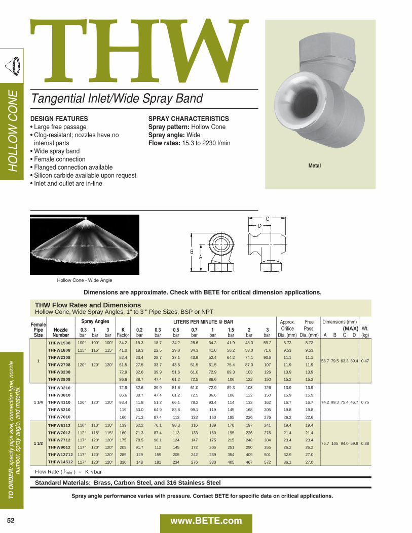
HOLLOW CONE
TO O
RD
ER:specify pipe size, connection type, nozzle
number, spray angle, and material.
52 www.BETE.com
THW
THW Flow Rates and Dimensions Hollow Cone, Wide Spray Angles, 1" to 3 " Pipe Sizes, BSP or NPT
Female Spray Angles LITERS PER MINUTE @ BAR Approx. Free
Pipe Nozzle 0.3 1 3 K 0.2 0.3 0.5 0.7 1 1.5 2 3 Orifice Pass. Dimensions (mm)
Wt. Size Number bar bar bar Factor bar bar bar bar bar bar bar bar Dia. (mm) Dia. (mm) A B C D (kg)
1
THFW1508 100° 100° 100° 34.2 15.3 18.7 24.2 28.6 34.2 41.9 48.3 59.2 8.73 8.73
58.7 79.5 63.3 39.4 0.47
THFW1808 115° 115° 115° 41.0 18.3 22.5 29.0 34.3 41.0 50.2 58.0 71.0 9.53 9.53
THFW2308 52.4 23.4 28.7 37.1 43.9 52.4 64.2 74.1 90.8 11.1 11.1
THFW2708 120° 120° 120° 61.5 27.5 33.7 43.5 51.5 61.5 75.4 87.0 107 11.9 11.9
THFW3208 72.9 32.6 39.9 51.6 61.0 72.9 89.3 103 126 13.9 13.9
THFW3808 86.6 38.7 47.4 61.2 72.5 86.6 106 122 150 15.2 15.2
1 1/4
THFW3210
120° 120° 120°
72.9 32.6 39.9 51.6 61.0 72.9 89.3 103 126 13.9 13.9
74.2 99.3 75.4 46.7 0.75
THFW3810 86.6 38.7 47.4 61.2 72.5 86.6 106 122 150 15.9 15.9
THFW4110 93.4 41.8 51.2 66.1 78.2 93.4 114 132 162 16.7 16.7
THFW5210 119 53.0 64.9 83.8 99.1 119 145 168 205 19.8 19.8
THFW7010 160 71.3 87.4 113 133 160 195 226 276 26.2 22.6
1 1/2
THFW6112 110° 110° 110° 139 62.2 76.1 98.3 116 139 170 197 241 19.4 19.4
75.7 105 94.0 59.9 0.88
THFW7012 112° 115° 115° 160 71.3 87.4 113 133 160 195 226 276 21.4 21.4
THFW7712 117° 120° 120° 175 78.5 96.1 124 147 175 215 248 304 23.4 23.4
THFW9012 117° 120° 120° 205 91.7 112 145 172 205 251 290 355 26.2 26.2
THFW12712 117° 120° 120° 289 129 159 205 242 289 354 409 501 32.9 27.0
THFW14512 117° 120° 120° 330 148 181 234 276 330 405 467 572 36.1 27.0
Flow Rate ( l ⁄min ) =
Standard Materials: Brass, Carbon Steel, and 316 Stainless Steel
T
O
Dia. (mm) Dia. (mm) A B C D (kg)
2
T
R l ⁄ ) K b
Brass, Carbon Steel, and 316 Stainless Steel
(
(MAX)
K √ bar
Tangential Inlet/Wide Spray BandDESIGN FEATURES• Large free passage• Clog-resistant; nozzles have no internal parts•Wide spray band• Female connection• Flanged connection available• Silicon carbide available upon request• Inlet and outlet are in-line
SPRAY CHARACTERISTICSSpray pattern: Hollow ConeSpray angle: WideFlow rates: 15.3 to 2230 l/min
Hollow Cone - Wide Angle
Metal
Dimensions are approximate. Check with BETE for critical dimension applications.
Spray angle performance varies with pressure. Contact BETE for specific data on critical applications.
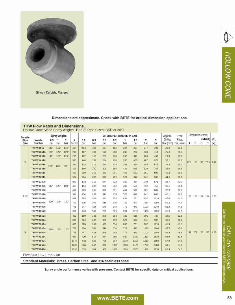
53www.BETE.com
HOLLO
W CONE
CALL 413-772-0846
Call for the nam
e of your nearest BETE representative.
Dia. (mm) Dia. (mm) A B C D (kg)
1
R ( l ⁄ =
Brass, Carbon Steel, and 316 Stainless Steel
THW Flow Rates and Dimensions Hollow Cone, Wide Spray Angles, 1" to 3" Pipe Sizes, BSP or NPT
Female Spray Angles LITERS PER MINUTE @ BAR Approx. Free
Pipe Nozzle 0.3 1 3 K 0.2 0.3 0.5 0.7 1 1.5 2 3 Orifice Pass.
Dimensions (mm)
Wt. Size Number bar bar bar Factor bar bar bar bar bar bar bar bar Dia. (mm) Dia. (mm) A B C D (kg)
2
THFW8516 112° 115° 115° 194 86.6 106 137 162 194 237 274 336 21.8 21.8
92.2 131 117 72.6 1.47
THFW10516 120° 120° 120° 239 107 131 169 200 239 293 338 414 25.4 25.4
THFW12516 119° 120° 120° 285 127 156 201 238 285 349 403 493 29.0 29.0
THFW14516 330 148 181 234 276 330 405 467 572 32.1 32.1
THFW17016 387 173 212 274 324 387 474 548 671 35.3 35.3
THFW19216 438 196 240 309 366 438 536 619 758 38.5 36.5
THFW20516 467 209 256 330 391 467 572 661 809 41.3 36.5
THFW23016 524 234 287 371 439 524 642 741 908 44.5 36.5
2 1/2
THFW17020 387 173 212 274 324 387 474 548 671 33.7 33.7
125 180 156 104 3.20
THFW19020 117° 120° 120° 433 194 237 306 362 433 530 612 750 36.1 36.1
THFW20520 467 209 256 330 391 467 572 661 809 37.3 37.3
THFW23020 524 234 287 371 439 524 642 741 908 40.1 40.1
THFW28020 638 285 349 451 534 638 781 902 1110 46.0 44.5
THFW32020 729 326 399 516 610 729 893 1030 1260 51.2 44.5
THFW34020 775 347 424 548 648 775 949 1100 1340 53.2 44.5
THFW43520 991 443 543 701 829 991 1210 1400 1720 61.9 44.5
3
THFW18524 422 189 231 298 353 422 516 596 730 32.5 32.5
149 209 182 117 4.29
THFW23024 524 234 287 371 439 524 642 741 908 36.5 36.5
THFW28024 638 285 349 451 534 638 781 902 1110 41.3 41.3
THFW32024 729 326 399 516 610 729 893 1030 1260 45.2 45.2
THFW34024 775 347 424 548 648 775 949 1100 1340 46.8 46.8
THFW41224 939 420 514 664 786 939 1150 1330 1630 53.6 53.6
THFW46924 1070 478 585 756 894 1070 1310 1510 1850 57.9 54.0
THFW52624 1200 536 657 848 1000 1200 1470 1700 2080 63.1 54.0
THFW56424 1290 575 704 909 1080 1290 1570 1820 2230 65.9 54.0
Flow Rate ( l ⁄min ) = K √ bar
Standard Materials: Brass, Carbon Steel, and 316 Stainless Steel
(MAX)
120° 120° 120°
120° 120° 120°
120° 120° 120°
Silicon Carbide, Flanged
Dimensions are approximate. Check with BETE for critical dimension applications.
Spray angle performance varies with pressure. Contact BETE for specific data on critical applications.

54
FAN
TO ORDER
:specify pipe size, connection type,
nozzle number, spray angle, and material.
www.BETE.com
Low FlowDESIGN FEATURES• Three-piece construction• Interchangeable spray tips• Integral strainer available (refer to page
119 for more information)• Male and female connections
SPRAY CHARACTERISTICS• Relatively coarse atomization• Uniform distribution with tapered edges
for use in overlapping spraysSpray pattern: Flat FanSpray angles: 0° to 110°Flow rate: 0.084 to 101 l/min
Fan 50° Fan 80°
Metal
48 mm
Flow Pipe Nozzle Rate @ Available Spray Angle Optional Strainer Wt.Size Number 3 bar 0° 15° 25° 40° 50° 65° 73° 80° 95° 110° Mesh Size (g)
BJ 0067 0.26 0° 15° 25° 40° 50° 65° BJ 0077 0.3 73° 100 28 BJ 01 0.39 0° 15° 25° 40° 50° 65° 80° 95° 110° BJ 0116 0.46 73° BJ 015 0.59 0° 15° 25° 40° 50° 65° 80° 95° 110° BJ 0154 0.61 73° BJ 02 0.79 0° 15° 25° 40° 50° 65° 80° 95° 110° BJ 0231 0.91 73° BJ 03 1.81 0° 15° 25° 40° 50° 65° 80° 95° 110° BJ 0308 1.22 73° BJ 0385 1.52 73° BJ 04 1.58 0° 15° 25° 40° 50° 65° 80° 95° 110° 50 28 BJ 0462 1.82 73° BJ 05 1.97 0° 15° 25° 40° 50° 65° 80° 95° 110° BJ 06 2.37 0° 15° 25° 40° 50° 65° 80° 95° 110° BJ 0616 2.43 73° BJ 077 3.04 73° BJ 08 3.16 0° 15° 25° 40° 50° 65° 80° 95° 110° BJ 0924 3.65 73° BJ 10 3.95 0° 15° 25° 40° 50° 65° 80° 95° 110° BJ 15 5.92 0° 15° 25° 40° 50° 65° 80° 95° 110° BJ 20 7.89 0° 15° 25° 40° 50° 65° 80° 95° 110° BJ 30 11.8 0° 15° 25° 40° 50° 65° 80° 95° 110° BJ 40 15.8 0° 15° 25° 40° 50° 65° 80° 95° 110° BJ 50 19.7 15° 25° 40° 50° 65° 80° 95° 110° 50 28 BJ 60 23.7 15° 25° 40° 50° 65° 80° 95° 110° BJ 70 27.6 15° 25° 40° 50° 65° 80° 95° 110°
Dimensions are approximate. Check with BETE for critical dimension applications.
BJ
1/8”
OR
1/4”
OR
3/8”
OR
1/2”
3/8”
OR
1/2”
Spray angle performance varies with pressure. Contact BETE for specific data on critical applications.
BJ DimensionsFan, 0° to 110° Spray Angles, 1/8", 1/4" and 3/8" Pipe Size, Male and Female

www.BETE.com
FAN
CALL 413-772-0846
Call for the nam
e of your nearest BE
TE
representative.
55
Ø15.0mm
Ø12.2mm
11.4mm2.0mm
TipCap Nut Body
BJ Flow RatesFan, 0°, 15°, 25°, 40°, 50°, 65°, 73°, 80°, 95°, 110° Spray Angles, 1/8", 1/4" and 3/8" Pipe Size, Male and Female
Dimensions in mm, C-Hex sizes in inches
Dimensions are approximate. Check with BETE for critical dimension applications.
Spray angle performance varies with pressure. Contact BETE for specific data on critical applications.
Optional Integral Strainer
LITERS PER MINUTE @ BAR
Equiv.
Pipe Nozzle Orifice K 0.3 0.5 0.7 2 4 5 10 20 30 40Size Number Dia. (mm) Factor bar bar bar bar bar bar bar bar bar bar BJ 0067 0.58 0.153 0.084 0.11 0.13 0.22 0.31 0.34 0.48 0.68 0.84 0.97 BJ 0077 0.58 0.175 0.096 0.12 0.15 0.25 0.35 0.39 0.55 0.78 0.96 1.11 BJ 01 0.71 0.228 0.12 0.16 0.19 0.32 0.46 0.51 0.72 1.02 1.25 1.44 BJ 0116 0.91 0.264 0.14 0.19 0.22 0.37 0.53 0.59 0.84 1.18 1.45 1.67 BJ 015 0.97 0.342 0.19 0.24 0.29 0.48 0.68 0.76 1.08 1.53 1.87 2.16 BJ 0154 0.84 0.351 0.19 0.25 0.29 0.50 0.70 0.78 1.11 1.57 1.92 2.22 BJ 02 0.99 0.456 0.25 0.32 0.38 0.64 0.91 1.02 1.44 2.04 2.50 2.88 BJ 0231 1.02 0.526 0.29 0.37 0.44 0.74 1.05 1.18 1.66 2.35 2.88 3.33 BJ 03 1.19 0.684 0.37 0.48 0.57 0.97 1.37 1.53 2.16 3.06 3.74 4.32 BJ 0308 1.19 0.702 0.38 0.50 0.59 0.99 1.40 1.57 2.22 3.14 3.84 4.44 BJ 0385 1.30 0.877 0.48 0.62 0.73 1.24 1.75 1.96 2.77 3.92 4.81 5.55 BJ 04 1.40 0.912 0.50 0.64 0.76 1.29 1.82 2.04 2.88 4.08 4.99 5.77 BJ 0462 1.42 1.053 0.58 0.74 0.88 1.49 2.11 2.35 3.33 4.71 5.77 6.66 BJ 05 1.55 1.139 0.62 0.81 0.95 1.61 2.28 2.55 3.60 5.10 6.24 7.21 BJ 06 1.70 1.367 0.75 0.97 1.14 1.93 2.73 3.06 4.32 6.11 7.49 8.65 BJ 0616 1.70 1.404 0.77 0.99 1.17 1.99 2.81 3.14 4.44 6.28 7.69 8.88 BJ 077 1.83 1.755 0.96 1.24 1.47 2.48 3.51 3.92 5.55 7.85 9.61 11.1 BJ 08 1.88 1.823 1.00 1.29 1.53 2.58 3.65 4.08 5.77 8.15 9.99 11.5 BJ 0924 1.98 2.106 1.15 1.49 1.76 2.98 4.21 4.71 6.66 9.42 11.5 13.3 BJ 10 2.18 2.279 1.25 1.61 1.91 3.22 4.56 5.10 7.21 10.2 12.5 14.4 BJ 15 2.72 3.418 1.87 2.42 2.86 4.83 6.84 7.64 10.8 15.3 18.7 21.6 BJ 20 3.18 4.558 2.50 3.22 3.81 6.45 9.12 10.2 14.4 20.4 25.0 28.8 BJ 30 3.67 6.837 3.74 4.83 5.72 9.67 13.7 15.3 21.6 30.6 37.4 43.2 BJ 40 3.97 9.116 4.99 6.45 7.63 12.9 18.2 20.4 28.8 40.8 49.9 57.7 BJ 50 4.37 11.394 6.24 8.06 9.53 16.1 22.8 25.5 36.0 51.0 62.4 72.1 BJ 60 4.76 13.673 7.49 9.67 11.4 19.3 27.3 30.6 43.2 61.1 74.9 86.5 BJ 70 5.16 15.952 8.74 11.3 13.3 22.6 31.9 35.7 50.4 71.3 87.4 101--
Flow Rate (l/min) = K Ö -barStandard Materials: Brass, 303 Stainless Steel, and 316 Stainless Steel (for nozzle number BJ01 and higher).
1/8”
OR
1/4”
OR
3/8”
OR
1/2”
3/8”OR1/2”
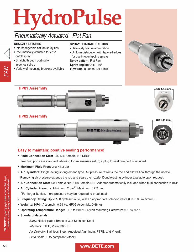
56
FAN
TO ORDER
:specify pipe size, connection type,
nozzle number, spray angle, and material.
www.BETE.com
Pneumatically Actuated - Flat FanSPRAY CHARACTERISTICS• Relatively coarse atomization• Uniform distribution with tapered edges
for use in overlapping spraysSpray pattern: Flat FanSpray angles: 0° to 110°Flow rate: 0.084 to 101 L/min
HydroPulse
Easy to maintain; positive sealing performance!• Fluid Connection Size: 1/8, 1/4, Female, NPT/BSP
Two fluid ports are standard, allowing for an in-series setup; a plug to seal one port is included.
• Maximum Fluid Pressure: 41.3 bar
• Air Cylinders: Single-acting spring extend type. Air pressure retracts the rod and allows flow through the nozzle.
Removing air pressure extends the rod and seals the nozzle. Double-acting cylinder available upon request.
• Air Connection Size: 1/8 Female NPT; 1/8 Female BSP Adapter automatically included when fluid connection is BSP
• Air Cylinder Pressure: Minimum: 2 bar*; Maximum: 17.2 bar.
*For larger BJ tips, more pressure may be required to break seal.
• Frequency Rating: Up to 180 cycles/minute, with an appropriate solenoid valve (Cv=0.08 minimum).
• Weights: HP01 Assembly: 0.59 kg; HP02 Assembly: 0.68 kg
• Operating Temperature Range: -26 ° to 204 °C. Nylon Mounting Hardware: 121 °C MAX
• Standard Materials:
Body: Nickel-plated Brass or 303 Stainless Steel
Internals: PTFE, Viton, 303SS
Air Cylinder: Stainless Steel, Anodized Aluminum, PTFE, and Viton®
Fluid Seals: FDA compliant Viton®
DESIGN FEATURES• Interchangeable flat fan spray tips• Pneumatically actuated for crisp
on/off spray• Straight through porting for in-series set-up• Variety of mounting brackets available
HP01 Assembly
HP02 Assembly
OD 1.44 mm
OD 1.44 mm

www.BETE.com
FAN
CALL 413-772-0846
Call for the nam
e of your nearest BE
TE
representative.
57
*HP02
ONLY
Flat Fan (BJ) - Fan Tip Dimensions
NozzleTip
Number
Equiv.OrificeDiameter(mm)
KFactor
LITERS PER MINUTE @ BARStandard
Available Spray Angles*0.3 bar 1 bar 2 bar 5 bar 10 bar 20 bar 40 bar
BJ 0067 0.580 0.153 0.084 0.153 0.220 0.340 0.480 0.680 0.970 0, 15, 25, 40, 50, 65, 80
BJ 0077 0.580 0.175 0.096 0.175 0.250 0.390 0.550 0.780 1.11 73
BJ 01 0.710 0.228 0.120 0.228 0.320 0.510 0.720 1.02 1.44 0, 15, 25, 40, 50, 65, 80, 95, 110
BJ 0116 0.910 0.264 0.140 0.264 0.370 0.590 0.840 1.18 1.67 73
BJ 015 0.970 0.342 0.190 0.342 0.480 0.760 1.08 1.53 2.16 0, 15, 25, 40, 50, 65, 80, 95, 110
BJ 02 0.990 0.456 0.250 0.456 0.640 1.02 1.44 2.04 2.88 0, 15, 25, 40, 50, 65, 80, 95, 110
BJ 03 1.19 0.684 0.370 0.684 0.970 1.53 2.16 3.06 4.32 0, 15, 25, 40, 50, 65, 80, 95, 110
BJ 04 1.40 0.912 0.500 0.912 1.29 2.04 2.88 4.08 5.77 0, 15, 25, 40, 50, 65, 80, 95, 110
BJ 05 1.55 1.14 0.620 1.14 1.61 2.55 3.60 5.10 7.21 0, 15, 25, 40, 50, 65, 80, 95, 110
BJ 06 1.70 1.37 0.750 1.37 1.93 3.06 4.32 6.11 8.65 0, 15, 25, 40, 50, 65, 80, 95, 110
BJ 08 1.88 1.82 1.00 1.82 2.58 4.08 5.77 8.15 11.5 0, 15, 25, 40, 50, 65, 80, 95, 110
BJ 10 2.18 2.28 1.25 2.28 3.22 5.10 7.21 10.2 14.4 0, 15, 25, 40, 50, 65, 80, 95, 110
BJ 15 2.72 3.42 1.87 3.42 4.83 7.64 10.8 15.3 21.6 0, 15, 25, 40, 50, 65, 80, 95, 110
BJ 20 3.18 4.56 2.5 4.56 6.45 10.2 14.4 20.4 28.8 0, 15, 25, 40, 50, 65, 80, 95, 110
BJ 30 3.67 6.84 3.74 6.84 9.67 15.3 21.6 30.6 43.2 0, 15, 25, 40, 50, 65, 80, 95, 110
BJ 40 3.97 9.12 4.99 9.12 12.9 20.4 28.8 40.8 57.7 0, 15, 25, 40, 50, 65, 80, 95, 110
BJ 50 4.37 11.4 6.24 11.4 16.1 25.5 36 51 72.1 15, 25, 40, 50, 65, 80, 95, 110
BJ 60 4.76 13.7 7.49 13.7 19.3 30.6 43.2 61.1 86.5 15, 25, 40, 50, 65, 80, 95, 110
BJ 70 5.16 16.0 8.74 16.0 22.6 35.7 50.4 71.3 101 15, 25, 40, 50, 65, 80, 95, 110
Flow Rate (L/min) = K√ bar
BJ tip materials: Brass, 303SS, and 316SS
A - Overall Length (mm)
HP01 HP02
152.4 192.8
Fan 80°
A
Spray angle performance varies with pressure. Contact BETE for specific data on critical applications.

58
FAN
TO ORDER
:specify pipe size, connection type,
nozzle number, spray angle, and material.
Optional Mounting Bracket Kits
HydroPulseKit 01Angle Bracket
Kit 02V-Block Bracket
Kit 03Clamp Bracket
Kit 04Direct MountV-Block Bracket
Brackets: 316 Stainless Steel; Hardware: 18-8SS with Nylon locking insert
In-series set-up possible; see instruction manual for more details.
Item Number Part Name
1 CAP NUT
2 TIP (BJ, BJH, CW, ST)
3 SEALING WASHER
4 FLOW CONDITIONER (HP 02 ONLY)
5 HEX SOCKET PLUG
6 BODY
7 SEALING TIP
8 JAM NUT
9 BUSHING O-RING
10 BUSHING
11 AIR CYLINDER O-RING (x2)
12 BACK-UP RING
13 COMPRESSIBLE BUSHING
14 AIR CYLINDER
2 3 41

CALL 413-772-0846
Call for the nam
e of your nearest BE
TE
representative.
59
Spray Set-up Number
Size1/8” 1/4”
Series Style01 02
Tip Series and NumberBJ (BJ20-70 only available for Body Style 02)
Mounting Hardware00 (no kit) 01 02 03 04
ThreadsB = BSP; omit for NPT
ActuationA B C
Spray Angle
1/4 HP01 BJ01 80 A 01 B
TO ORDER
HP 01PneumaticCylinder
HP 02PneumaticCylinder
HP 01Double-actingPneumaticCylinder
www.BETE.com
HydroPulse 01
HP01 Sealing Kit
HP02 Sealing Kit
3 7 8 9 11 12 13
HydroPulse 02
11
11
11
11
HydroPulse® Components & Options
5 6 7 8 9 10 11 12 13 14
FAN

60
FAN
TO ORDER
:specify pipe size, connection type,
nozzle number, spray angle, and material.
www.BETE.com
NFVFan Nozzle with Integral Strainer Option
DESIGN FEATURES• One-piece construction• No internal parts• Male connection• Low nozzle maintenance• Optional removable strainer for easy cleaningConnections: Male NPT and BSPOptional Strainer: 50, 100, 200 mesh
SPRAY CHARACTERISTICS• High impact• Uniform distribution
Spray pattern: Flat Fan and Straight JetSpray angles: 0°, 15°, 25°, 40°, 50°, 65°,80°, 95°, and 110°Flow rates: 0.15 to 49.85 l/minNFV0067: Max. spray angle available 95°
Fan 50°
MetalShown with Optional Strainer
1/8” - 1/4” Metal
B
A
Call BETE to verify spray angle performanceat operating pressures above 30 bar.
CNFV Dimensions
PipeSize
Dimensions (mm) Wt.(g)
A B C
1/8 22.4 11.2 37.9 28.4
1/4 26.9 14.2 42.9 42.5
Flow Rate (L/min) = K Ö bar Standard Materials: Brass and 303 Stainless Steel. Highlighted NFVs available in 316 Stainless Steel.
1/4 NFV 0067 95 -L -B 303
To Order: Spray Set-up Number
pipe size specify materialseries
BSP threadnozzle number
spray angle optional strainer, also specify mesh size
Spray angle performance varies with pressure. Contact BETE for specific data on critical applications.
Screen MeshSelectionGuide
100
100100
100505050505050505050505050
NFV Flow RatesFan and Straight Jet, 0°, 15°, 25°, 40°, 50°, 65°, 80°, 95° (all sizes); 110° (NFV01 and higher)
Male PipeSize
Nozzle Number
K FactorLITERS PER MINUTE @ BAR Equiv.
Orifice Dia. (mm)1 2 3 5 10 30
bar bar bar bar bar barNFV0067** 0.153 0.15 0.22 0.26 0.34 0.48 0.84 0.58NFV01 0.228 0.23 0.32 0.39 0.51 0.72 1.25 0.66NFV015 0.342 0.34 0.48 0.59 0.76 1.08 1.87 0.79NFV02 0.456 0.46 0.64 0.79 1.02 1.44 2.50 0.91NFV025 0.569 0.57 0.80 0.99 1.27 1.80 3.12 1.02NFV03 0.684 0.68 0.97 1.18 1.53 2.16 3.75 1.09NFV04 0.912 0.91 1.29 1.58 2.04 2.88 5.00 1.32NFV05 1.139 1.14 1.61 1.97 2.55 3.60 6.24 1.45NFV06 1.367 1.37 1.93 2.37 3.06 4.32 7.48 1.57NFV07 1.598 1.60 2.26 2.77 3.57 5.05 8.75 2.08NFV08 1.823 1.82 2.58 3.16 4.08 5.76 9.98 1.83NFV10 2.279 2.28 3.22 3.95 5.10 7.21 12.48 2.03NFV15 3.418 3.42 4.83 5.92 7.64 10.81 18.72 2.39NFV20 4.550 4.55 6.44 7.88 10.18 14.39 24.92 2.77NFV30 6.826 6.83 9.65 11.82 15.26 21.58 37.39 3.58NFV40 9.101 9.10 12.87 15.76 20.35 28.78 49.85 3.96
1/8”
or
1/4”
**NFV0067: Max. spray angle available: 95°

www.BETE.com
FAN
CALL 413-772-0846
Call for the nam
e of your nearest BE
TE
representative.
61
NFStandard Fan Nozzle
DESIGN FEATURES• One-piece construction• No internal parts• Sizes for all applications• Male connection
SPRAY CHARACTERISTICS• High impact• Uniform distribution with tapered edges
for overlapping sprays• Extra-wide angles availableSpray pattern: Fan and Straight JetSpray angles: 0° to 120°Flow rates: 0.161 to 3430 l/min
Fan 50°
Metal
NF Flow Rates NF Dimensions Fan and Straight Jet, 0°, 15°, 30°, 50°, 65°, 80°, 90°, 110°, and 120° Spray Angles, 1/8" to 2" Pipe Sizes BSP or NPT
Male LITERS PER MINUTE @ BAR Equivalent Dim. for Metal Pipe Nozzle K 0.5 0.7 1 2 3 5 10 30 Orifice Pipe Only (mm) Wt. (g) Size Number Factor bar bar bar bar bar bar bar bar Dia. (mm) Size A B Metal Plas.
NF01 0.228 0.16 0.19 0.23 0.32 0.39 0.51 0.72 1.25 0.66 1/8 22.2 11.1 28.4 7.09 1/8 NF015 0.342 0.24 0.29 0.34 0.48 0.59 0.76 1.08 1.87 0.79
NF02 0.455 0.32 0.38 0.46 0.64 0.79 1.02 1.44 2.49 0.91 or NF025 0.569 0.40 0.48 0.57 0.81 0.99 1.27 1.80 3.12 1.02
NF03 0.683 0.48 0.57 0.68 0.97 1.18 1.53 2.16 3.74 1.09
1/4 27.0 14.3 42.5 10.6 1/4 NF04 0.911 0.64 0.76 0.91 1.29 1.58 2.04 2.88 4.99 1.32 NF05 1.14 0.81 0.95 1.14 1.61 1.97 2.55 3.60 6.24 1.45 NF06 1.37 0.97 1.14 1.37 1.93 2.37 3.06 4.33 7.49 1.57 NF08 1.82 1.28 1.52 1.82 2.57 3.15 4.06 5.74 9.95 1.83
3/8 31.8 17.5 56.7 14.2 1/8 NF10 2.28 1.61 1.91 2.28 3.22 3.95 5.10 7.21 12.5 2.03 or NF15 3.42 2.42 2.86 3.42 4.83 5.92 7.64 10.8 18.7 2.38 1/4 NF20 4.56 3.22 3.81 4.56 6.45 7.89 10.2 14.4 25.0 2.78 or NF30 6.84 4.83 5.72 6.84 9.67 11.8 15.3 21.6 37.4 3.57
1/2 38.1 22.2 85.1 28.4 3/8 NF40 9.12 6.45 7.63 9.12 12.9 15.8 20.4 28.8 49.9 3.97
1/4 NF50 11.4 8.06 9.53 11.4 16.1 19.7 25.5 36.0 62.4 4.37 or NF60 13.7 9.67 11.4 13.7 19.3 23.7 30.6 43.2 74.9 4.76 3/8 NF70 16.0 11.3 13.3 16.0 22.6 27.6 35.7 50.4 87.4 5.16
3/4 44.5 28.6 170 42.5 NF60 13.7 9.67 11.4 13.7 19.3 23.7 30.6 43.2 74.9 4.76 3/8 NF70 16.0 11.3 13.3 16.0 22.6 27.6 35.7 50.4 87.4 5.16 or NF80 18.2 12.9 15.3 18.2 25.8 31.6 40.8 57.7 99.9 5.56 1/2 NF90 20.5 14.5 17.2 20.5 29.0 35.5 45.9 64.9 112 5.95
1 55.6 34.9 227 56.7 NF100 22.8 16.1 19.1 22.8 32.2 39.5 51.0 72.1 125 6.35 NF120 27.3 19.3 22.9 27.3 38.7 47.4 61.1 86.5 150 6.75
1/2 NF150 34.2 24.2 28.6 34.2 48.3 59.2 76.4 108 187 7.54 NF200 45.6 32.2 38.1 45.6 64.5 78.9 102 144 250 8.73
1 1/4 63.5 44.5 340 85.1 3/4 NF300 68.4 48.3 57.2 68.4 96.7 118 153 216 374 10.7
NF400 91.2 64.5 76.3 91.2 129 158 204 288 499 12.7
1 NF400 91.2 64.5 76.3 91.2 129 158 204 288 499 12.7 1 1/2 76.2 50.8 567 142 NF750 171 121 143 171 242 296 382 540 936 17.5
1 1/4 NF800 182 129 153 182 258 316 408 577 999 18.3 NF1150 262 185 219 262 371 454 586 829 1440 21.8
2 88.9 63.5 1588 284 1 1/2 NF1500 342 242 286 342 483 592 764 1080 1870 24.6
2 NF2250 513 362 429 513 725 890 1150 1620 2810 30.2
Flow Rate ( l ⁄min ) = K √√ bar Standard Materials: Brass, 303 Stainless Steel, 316 Stainless Steel, PVC, and PTFE (PTFE not available in nozzle numbers NF025 and under)
Call BETE to verify spray angle performance at operating pressures above 5 bar.
3/8” - 2” Metal
B
A
Dimensions are approximate. Check with BETE for critical dimension applications.
Spray angle performance varies with pressure. Contact BETE for specific data on critical applications.
Call BETE to verify spray angle performance at operating pressures above 5 bar.

NFD ComponentsNFD Base
Offset Angle -EMale Base
Cap- A, B, C
Tip- A, B, C
WeldBase
Female Base
NFDDESIGN FEATURES• Dovetail joint guarantees alignment of interchangeable tips• Dimensionally compatible with other dovetail systems• Tips offset 5° or 15° for overlapping spray patterns• Tapered overlapping spray provides uniform coverage • Male, female and welded connections• Other sizes available upon request
SPRAY CHARACTERISTICS• Spray pattern: Flat Fan • Spray angles: 20°, 30°, 45°, 60°, 90°, and 120°. Special angles are available on request• Flow rates: 0.159 to 358 l/min
Dovetail Flat Fan
Fan 45°
Metal
NFD Flow Rates and DimensionsFan, 20°, 30°, 45°, 60°, 90°, 120° Spray Angles, 1/4", 3/8”, 1/2”, 3/4" and 1-1/4" Pipe Size, BSP or NPT, or Welded Connections
LITERS PER MINUTE @ BARCap & Base Equiv. Approximate Tip BSP Approx. BaseTip Nozzle Sizes* K 0.5 1 2 3 5 7 10 Orifice Dimensions (mm) Wt. NPT Dim. (mm)Size Number Available Factor bar bar bar bar bar bar bar Dia. (mm) A B C D E (g) Pipe J K
NFD 010 1/4 3/8 1/2 0.225 0.159 0.225 0.318 0.390 0.503 0.596 0.712 0.700NFD 014 1/4 3/8 1/2 0.318 0.225 0.318 0.449 0.550 0.710 0.840 1.00 0.900NFD 019 1/4 3/8 1/2 0.445 0.314 0.445 0.629 0.770 0.994 1.18 1.41 1.00 14.8 1/4” 17.5 36.5NFD 031 1/4 3/8 1/2 0.704 0.498 0.704 0.996 1.22 1.58 1.86 2.23 1.20NFD 039 1/4 3/8 1/2 0.883 0.625 0.883 1.25 1.53 1.98 2.34 2.79 1.35 12 5° 42
A NFD 050 1/4 3/8 1/2 1.13 0.800 1.13 1.60 1.96 2.53 2.99 3.58 1.50NFD 059 1/4 3/8 1/2 1.34 0.947 1.34 1.89 2.32 3.00 3.54 4.24 1.65 7NFD 077 1/4 3/8 1/2 1.77 1.25 1.77 2.50 3.06 3.95 4.67 5.59 2.00NFD 097 1/4 3/8 1/2 2.22 1.57 2.22 3.14 3.85 4.97 5.88 7.03 2.20 12 3/8” 17.5 36.5NFD 12 1/4 3/8 1/2 2.82 2.00 2.82 3.99 4.89 6.31 7.47 8.93 2.50NFD 15 1/4 3/8 1/2 3.35 2.37 3.35 4.74 5.81 7.50 8.87 10.6 2.70NFD 20 3/4 4.45 3.15 4.45 6.30 7.71 10.0 11.8 14.1 3.00NFD 25 3/4 5.65 4.00 5.65 7.99 9.79 12.6 15.0 17.9 3.50NFD 31 3/4 7.04 4.98 7.04 9.96 12.2 15.8 18.6 22.3 4.00 24 1/2“ 22 44.5 NFD 39 3/4 8.83 6.25 8.83 12.5 15.3 19.8 23.4 27.9 4.50NFD 50 3/4 11.3 8.00 11.3 16.0 19.6 25.3 29.9 35.8 5.00
B NFD 62 3/4 14.1 10.0 14.1 20.0 24.5 31.6 37.4 44.7 5.50 15 15° 168NFD 77 3/4 17.7 12.5 17.7 25.0 30.6 39.5 46.7 55.9 6.00NFD 87 3/4 19.8 14.0 19.8 28.0 34.3 44.3 52.4 62.6 6.40 9 3/4” 28.5 51NFD 104 3/4 23.7 16.7 23.7 33.5 41.0 52.9 62.6 74.9 7.20NFD 124 3/4 28.3 20.0 28.3 40.0 49.0 63.3 74.8 89.5 8.00 20NFD 155 3/4 35.3 25.0 35.3 50.0 61.2 79.0 93.5 112 9.00NFD 195 3/4 44.5 31.4 44.5 62.9 77.0 99.4 118 141 10.0
NFD 124 1-1/4 28.3 20.0 28.3 40.0 49.0 63.2 74.8 89.5 8.00NFD 195 1-1/4 44.5 31.4 44.5 62.9 77.0 99.4 118 141 10.0 38.5 22 13.5 32 15° 224 1-1/4” 44.5 63.5C NFD 309 1-1/4 70.4 49.8 70.4 100 122 158 186 223 12.0NFD 496 1-1/4 113 80.0 113 160 196 253 299 358 15.0--
Flow Rate (l/min) = K √ bar * NPT, BSP, male or female or weldable connections. Dimensions are for male base, female and weldable vary.
Standard Materials: Brass, 303 Stainless Steel, and 316 Stainless Steel Weldable adapters also available in mild steel.
NFD Tip
Dimensions are approximate. Check with BETE for critical dimension applications.
Assemblywith weldedconnection
Spray angle performance varies with pressure. Contact BETE for specific data on critical applications.
62
FAN
TO ORDER
:specify pipe size, connection type,
nozzle number, spray angle, and material.
www.BETE.com

FAN
CALL 413-772-0846
Call for the nam
e of your nearest BE
TE
representative.
63
Flow Rate (l/min) = K Ö bar
Standard Materials: Brass, 316 Stainless Steel, 303 Stainless Steel, and PVC
DESIGN FEATURES• Extremely short length for minimum projection and
maximum clearance• Produces a flat fan spray pattern available in a variety of spray angles• Available in straight (parallel) threads only, NPSM and G• Requires gasket to seal connection
SPRAY CHARACTERISTICSSpray pattern: FanSpray angles: 20°, 30°, 45°, 60°, 90° and 120° standardFlow rates: 0.20 to 951 l/min
Fan 45° Fan 90°Metal Plastic
Stubby Flat Fan
Metal
NFS Flow Rates and DimensionsFlat Fan, 20°, 30°, 45°, 60°, 90° & 120° Spray Angles, 1/4" to 2" Pipe Sizes NFS Dimensions and
Spray Angles
Spray DimensionsPipe Nozzle Angles (mm)Size Number Available A B C D NFS 012 20° 30° 45° 11.9 To 60° 90° 120° NFS 39 7.11
1/4 NFS 50 20° 30° 45° 60° 90° 17.5
NFS 62 45° 60° 90°
NFS 77 45° 19.1
NFS 20 20° 30° 45° 15.0 To 60° 90° 120° NFS 77
NFS 93* 120° 7.87
3/4 NFS 124 20° 30° 45° 60° 90° 120°
NFS 155 20° 30° 45° 31.8 60° 90° 120°
NFS 185 120°
NFS 195 20° 30° 45° 35.1 60° 90° 120°
NFS 309 20° 30° 45° 60° 90° 120°
NFS 124 20° 30° 45° 22.1 11.91¼ To 60° 90° 120° 50.8 NFS 496 55.4
NFS 557 20° 30° 45° 31.8 20.12 To 60° 90° 120° 69.9 NFS 1320 76.2
LITERS PER MINUTE @ BAR Male Equiv.Pipe Nozzle K 0.5 1 2 3 5 7 10 OrificeSize Number Factor bar bar bar bar bar bar bar Dia. (mm)
NFS 012 0.28 0.20 0.28 0.40 0.49 0.63 0.75 0.89 0.800 NFS 019 0.44 0.31 0.44 0.63 0.77 0.99 1.18 1.41 1.00 NFS 031 0.71 0.50 0.71 1.00 1.23 1.59 1.88 2.25 1.20 NFS 039 0.88 0.62 0.88 1.25 1.53 1.98 2.34 2.79 1.35
1/4” NFS 050 1.13 0.80 1.13 1.60 1.96 2.53 2.99 3.58 1.50 NFS 059 1.35 0.95 1.35 1.90 2.33 3.01 3.56 4.25 1.65 NFS 077 1.77 1.25 1.77 2.50 3.06 3.95 4.67 5.59 2.00 NFS 098 2.23 1.58 2.23 3.15 3.86 4.98 5.90 7.05 2.20 NFS 12 2.83 2.00 2.83 4.00 4.90 6.33 7.48 8.95 2.50 NFS 15 3.36 2.38 3.36 4.75 5.82 7.51 8.89 10.6 2.70 NFS 20 4.56 3.22 4.56 6.45 7.89 10.2 12.1 14.4 3.00
NFS 25 5.66 4.00 5.66 8.00 9.80 12.7 15.0 17.9 3.501/4” NFS 31 7.10 5.02 7.10 10.0 12.3 15.9 18.8 22.5 4.00or NFS 39 8.83 6.25 8.83 12.5 15.3 19.8 23.4 27.9 4.503/4" NFS 50 11.3 8.00 11.3 16.0 19.6 25.3 29.9 35.8 5.00
NFS 62 14.1 10.0 14.1 20.0 24.5 31.6 37.4 44.7 5.50 NFS 77 17.7 12.5 17.7 25.0 30.6 39.5 46.7 55.9 6.00
3/4” NFS 93 21.2 15.0 21.2 30.0 36.7 47.4 56.1 67.0 6.903/4” NFS 124 28.3 20.0 28.3 40.0 49.0 63.3 74.8 89.5 8.00or NFS 155 35.3 25.0 35.3 50.0 61.2 79.0 93.5 112 9.001-1/4” NFS 185 42.1 29.8 42.1 59.6 73.0 94.2 112 133 9.50
NFS 195 44.6 31.5 44.6 63.0 77.2 100 118 141 10.0 NFS 309 70.4 49.8 70.4 100 122 158 186 223 12.01-1/4”
NFS 496 113 80.0 113 160 196 253 299 358 15.0 NFS 557 127 89.8 127 180 220 284 336 402 16.0
NFS 620 141 100 141 200 245 316 374 447 17.0 NFS 775 177 125 177 250 306 395 467 559 19.0
2” NFS 977 223 158 223 315 386 498 590 705 21.0 NFS 1130 258 182 258 365 447 577 683 816 22.5 NFS 1320 301 213 301 425 521 673 796 951 24.5
**
**Available in straight (parallel) threads only, NPSM and G
Dimensions are approximate. Check with BETE for critical dimension applications.
NFS
Spray angle performance varies with pressure. Contact BETE for specific data on critical applications.
www.BETE.com

FF
FF Flow Rates FF Fan, 105° and 145° Spray Angle, 1/8" to 1" Pipe Sizes, BSP or NPT Dimensions
Male LITERS PER MINUTE @ BAR Approx. Pipe Nozzle Spray K 0.2 0.5 0.7 1 2 3 5 10 Orifice Pipe Dim. (mm) Wt. (g) Size Number Angle Factor bar bar bar bar bar bar bar bar Dia. (mm) Size A B C M P
1/8
FF016 105° 0.114 0.0510 0.0806 0.0953 0.114 0.161 0.197 0.255 0.360 0.406
1/8 25.4 11.2 12.7 14 3
FF024 105° 0.228 0.102 0.161 0.191 0.228 0.322 0.395 0.510 0.721 0.610
FF028 105° 0.342 0.153 0.242 0.286 0.342 0.483 0.592 0.764 1.08 0.711
FF033 105° 0.456 0.204 0.322 0.381 0.456 0.645 0.789 1.02 1.44 0.838
FF041 145° 0.684 0.306 0.483 0.572 0.684 0.967 1.18 1.53 2.16 1.04
FF046 145° 0.912 0.408 0.645 0.763 0.912 1.29 1.58 2.04 2.88 1.17
FF052 145° 1.14 0.510 0.806 0.953 1.14 1.61 1.97 2.55 3.60 1.32
FF057 145° 1.37 0.611 0.967 1.14 1.37 1.93 2.37 3.06 4.32 1.45
FF065 145° 1.82 0.815 1.29 1.53 1.82 2.58 3.16 4.08 5.77 1.65
FF073 145° 2.28 1.02 1.61 1.91 2.28 3.22 3.95 5.10 7.21 1.85
FF093 145° 3.42 1.53 2.42 2.86 3.42 4.83 5.92 7.64 10.8 2.36
1/8 FF104 145° 4.56 2.04 3.22 3.81 4.56 6.45 7.89 10.2 14.4 2.64
or FF116 145° 5.47 2.45 3.87 4.58 5.47 7.73 9.47 12.2 17.3 2.95
1/4 35.1 14.2 16.0 35 7.5
1/4 FF125 145° 5.70 2.55 4.03 4.77 5.70 8.06 9.87 12.7 18.0 3.18
FF129 145° 6.84 3.06 4.83 5.72 6.84 9.67 11.8 15.3 21.6 3.28
FF141 145° 8.20 3.67 5.80 6.86 8.20 11.6 14.2 18.3 25.9 3.58
FF148 145° 9.12 4.08 6.45 7.63 9.12 12.9 15.8 20.4 28.8 3.76
1/4
FF156 145° 10.0 4.48 7.09 8.39 10.0 14.2 17.4 22.4 31.7 3.96
FF161 145° 10.9 4.89 7.73 9.15 10.9 15.5 18.9 24.5 34.6 4.09
FF173 145° 12.3 5.50 8.70 10.3 12.3 17.4 21.3 27.5 38.9 4.39
Standard Materials: Brass, 303 Stainless Steel, 316 Stainless Steel, PVC, and PTFE
F D
Spray K 0.2 0.5 0.7 1 2 3 5 10 O
1
1
Brass, 303 Stainless Steel, 316 Stainless Steel, PVC, and PTFE.
(PTFE and PVC not available in nozzles FF016 to FF028; PTFE not available in nozzles FF033 to FF065).
Flow Rate ( l ⁄min ) = K √ bar
F
Extra-Wide Angle
DESIGN FEATURES• One-piece construction• Clog resistant• Durable• All 3/8” FFs in Brass are available with
UL approval• Male connection
SPRAY CHARACTERISTICS• Extra-wide 145° spray angle• Medium-impact spray• Spray discharge deflected 75° from
inlet axis• Coarse atomizationSpray pattern: Flat FanSpray angle: 105° or 145°, as listedFlow rates: 0.510 to 757 l/min
Fan 145° Metal Plastic
Plastic
Dimensions are approximate. Check with BETE for critical dimension applications.
Spray angle performance varies with pressure. Contact BETE for specific data on critical applications.
64
FAN
TO ORDER
:specify pipe size, connection type,
nozzle number, spray angle, and material.
www.BETE.com

FAN
CALL 413-772-0846
Call for the nam
e of your nearest BE
TE
representative.
65www.BETE.com
Metal
Metal Plastic
All 3/8” FFs in Brass have UL approval
F F
Spray K 0.2 0.5 0.7 1 2 3 5 10 O
1
1
1
1
1
1
1
1
1
1
1
Brass, 303 Stainless Steel, 316 Stainless Steel, PVC, and PTFE
FF Dimensions
Male LITERS PER MINUTE @ BAR Approx. Pipe Nozzle Spray K 0.2 0.5 0.7 1 2 3 5 10 Orifice Pipe Dim. (mm) Wt. (g) Size Number Angle Factor bar bar bar bar bar bar bar bar Dia (mm) Size A B C M P
3/8
FF187 145° 13.7 6.11 9.67 11.4 13.7 19.3 23.7 30.6 43.2 4.75
3/8 44.5 17.5 19.1 72 15 FF196 145° 16.0 7.1 11.3 13.3 16.0 22.6 27.6 35.7 50.4 4.98
FF209 145° 17.0 7.6 12.0 14.2 17.0 24.0 29.4 38.0 53.8 5.31
FF221 145° 20.5 9.2 14.5 17.2 20.5 29.0 35.5 45.9 64.9 5.61
1/2
FF218 145° 18.2 8.2 12.9 15.3 18.2 25.8 31.6 40.8 57.7 5.54
1/2 50.8 22.4 22.4 117 25
FF250 145° 23.9 10.7 16.9 20.0 23.9 33.8 41.4 53.5 75.7 6.35
FF256 145° 27.3 12.2 19.3 22.9 27.3 38.7 47.4 61.1 86.5 6.55
FF281 145° 31.9 14.3 22.6 26.7 31.9 45.1 55.3 71.3 101 7.14
FF312 145° 36.5 16.3 25.8 30.5 36.5 51.6 63.2 81.5 115 7.92
FF375 145° 54.7 24.5 38.7 45.8 54.7 77.3 94.7 122 173 9.53
3/4
FF316 145° 41.0 18.3 29.0 34.3 41.0 58.0 71.0 92 130 8.03
3/4 66.8 38.1 38.1 345 73
FF332 145° 45.6 20.4 32.2 38.1 45.6 64.5 78.9 102 144 8.43
FF348 145° 50.1 22.4 35.5 41.9 50.1 70.9 86.8 112 159 8.84
FF368 145° 54.7 24.5 38.7 45.8 54.7 77.3 94.7 122 173 9.35
FF406 145° 63.8 28.5 45.1 53.4 63.8 90.2 111 143 202 10.3
FF437 145° 72.9 32.6 51.6 61.0 72.9 103 126 163 231 11.1
FF453 145° 82.0 36.7 58.0 68.6 82.0 116 142 183 259 11.5
FF484 145° 95.7 42.8 67.7 80.1 95.7 135 166 214 303 12.3
FF500 145° 109 48.9 77.3 91.5 109 155 189 245 346 12.7
1
FF578 145° 137 61.1 96.7 114 137 193 237 306 432 14.7
1 85.9 50.8 50.8 908 192FF625 145° 166 74.4 118 139 166 235 288 372 526 15.9
FF703 145° 205 91.7 145 172 205 290 355 459 649 17.9
FF750 145° 239 107 169 200 239 338 414 535 757 19.1
Flow Rate (l ⁄min ) = K √ bar
Standard Materials: Brass, 303 Stainless Steel, 316 Stainless Steel, PVC, and PTFE.
FF209 145° 5.3117.0 7.6 12.0 14.2 17.0 24.0 29.4 38.0 53.8
PTFE not available in nozzles FF033 to FF065).
F
FF218 145° 18.2 8.2 12.9 15.3 18.2 25.8 31.6 40.8 57.7 5.54
FF Flow Rates Fan, 105° and 145° Spray Angle, 1/8" to 1 " Pipe Sizes, BSP or NPT
FF375 145° 54.7 24.5 38.7 45.8 54.7 77.3 94.7 122 173 9.53
Dimensions are approximate. Check with BETE for critical dimension applications.
Spray angle performance varies with pressure. Contact BETE for specific data on critical applications.

66
FAN
www.BETE.com
EZFF NF SPN
LITERS PER MINUTE @ BAR Approx.
Approx. AssemblyPipe Nozzle K 0.2 0.5 0.7 1 2 3 5 Orifice Pipe Dim. (mm) Wt.Size Number Factor bar bar bar bar bar bar bar Dia. (mm) Size Hex Length (g)
EZFF016+ 0.114 0.051 0.081 0.095 0.114 0.161 0.197 0.255 0.406 EZFF024+ 0.228 0.102 0.161 0.191 0.228 0.322 0.395 0.510 0.610 EZFF028+ 0.342 0.153 0.242 0.286 0.342 0.483 0.592 0.764 0.711 EZFF033+ 0.456 0.204 0.322 0.381 0.456 0.645 0.789 1.02 0.838 1/8 22.4 41.4 62
1/8” EZFF041 0.684 0.306 0.483 0.572 0.684 0.967 1.18 1.53 1.04 EZFF046 0.912 0.408 0.645 0.763 0.912 1.29 1.58 2.04 1.17 EZFF052 1.14 0.510 0.806 0.953 1.14 1.61 1.97 2.55 1.32 EZFF057 1.37 0.611 0.967 1.14 1.37 1.93 2.37 3.06 1.45 EZFF065 1.82 0.815 1.29 1.53 1.82 2.58 3.16 4.08 1.65 EZFF073 2.28 1.02 1.61 1.91 2.28 3.22 3.95 5.10 1.85 1/4” 22.4 44.5 62
TO EZFF093 3.42 1.53 2.42 2.86 3.42 4.83 5.92 7.64 2.36 EZFF104 4.56 2.04 3.22 3.81 4.56 6.45 7.89 10.2 2.64 EZFF116 5.47 2.45 3.87 4.58 5.47 7.73 9.47 12.2 2.95 EZFF125 5.70 2.55 4.03 4.77 5.70 8.06 9.87 12.7 3.18 EZFF129 6.84 3.06 4.83 5.72 6.84 9.67 11.8 15.3 3.28 EZFF141 8.20 3.67 5.80 6.86 8.20 11.6 14.2 18.3 3.58 3/8” 22.4 46.0 74 EZFF148 9.12 4.08 6.45 7.63 9.12 12.9 15.8 20.4 3.76
1/2” EZFF156 10.0 4.48 7.09 8.39 10.0 14.2 17.4 22.4 3.96 EZFF161 10.9 4.89 7.73 9.15 10.9 15.5 18.9 24.5 4.09 EZFF173 12.3 5.50 8.70 10.3 12.3 17.4 21.3 27.5 4.39 EZFF187 13.7 6.11 9.67 11.4 13.7 19.3 23.7 30.6 4.75 EZFF196 16.0 7.13 11.3 13.3 16.0 22.6 27.6 35.7 4.98 1/2” 22.4 47.5 82
1/4” EZFF218 18.2 8.15 12.9 15.3 18.2 25.8 31.6 40.8 5.31 TO EZFF221 20.5 9.17 14.5 17.2 20.5 29.0 35.5 45.9 5.611/2” EZFF250 23.9 10.7 16.9 20.0 23.9 33.8 41.4 53.5 6.35
EZFF256 27.3 12.2 19.3 22.9 27.3 38.7 47.4 61.1 6.55
Flow Rate (l/min) = K Ö bar +Available in 105° only; all others 145°
Standard Materials: 303 Stainless Steel, 316 Stainless Steel, and Brass; Viton gaskets standard.
DESIGN FEATURES• Nozzles can be changed in seconds
without tools• Three part nozzle, base, gasket and
interchangeable tip• Exclusive ramped engagement for effi-
cient automatic alignment • Threaded adapters will accommodate
other standard BETE nozzles. Shut-offplugs are also available.
• Sanitary EZs are available with weldconnection and no knurling
SPRAY CHARACTERISTICS• Available in six standard tips:
EZFF; EZNF; EZSPN; EZWL; EZTF,and EZWT
More EZ tips:Full Cone: page 28Hollow Cone: page 46Flow rates: 0.051 to 125 l/minSpray Angle:EZFF: 105° and 145°EZNF: 0°, 15°, 30°, 50°, 65°, 80°, 90°,110°, 120°EZSPN: 15°, 25°, 35°, 40°and 50°
EZ Change Quick Connection System
145° Fan 50° Fan
EZFF Flow Rates and DimensionsDeflected Flat Fan 105° and 145° Spray Angles 1/8” to 1/2” BSP or NPT
EZNF
EZNF exploded
Base Gasket Tip
Dimensions are approximate. Check with BETE for critical dimension applications.
Spray angle performance varies with pressure. Contact BETE for specific data on critical applications.
TO ORDER
:specify pipe size, connection type,
nozzle number, spray angle, and material.

LITERS PER MINUTE @ BAR Approx. Equivalent AssemblyPipe Nozzle K 0.2 0.5 0.7 1 2 3 5 10 15 20 30 35 Orifice Dim. (mm) Wt.Size Number Factor bar bar bar bar bar bar bar bar bar bar bar bar Dia. (mm) Hex Length (g)
EZNF01 0.228 0.161 0.191 0.228 0.322 0.394 0.509 0.720 0.882 1.02 1.25 1.35 0.660EZNF015 0.342 0.242 0.286 0.342 0.483 0.592 0.764 1.08 1.32 1.53 1.87 2.02 0.787EZNF02 0.455 0.322 0.381 0.455 0.644 0.789 1.02 1.44 1.76 2.04 2.49 2.69 0.914 1/8” 22.4 41.4 62EZNF025 0.569 0.403 0.476 0.569 0.805 0.986 1.27 1.80 2.20 2.55 3.12 3.37 1.02EZNF03 0.683 0.483 0.572 0.683 0.966 1.18 1.53 2.16 2.65 3.06 3.74 4.04 1.09
1/8” EZNF04 0.911 0.644 0.762 0.911 1.29 1.58 2.04 2.88 3.53 4.07 4.99 5.39 1.32EZNF05 1.14 0.806 0.953 1.14 1.61 1.97 2.55 3.60 4.41 5.10 6.24 6.74 1.45 1/4” 22.4 44.5 62
TO EZNF06 1.37 0.612 0.967 1.14 1.37 1.93 2.37 3.06 4.33 5.30 6.12 7.49 8.09 1.57EZNF08 1.82 0.812 1.28 1.52 1.82 2.57 3.15 4.06 5.74 7.03 8.12 9.95 10.7 1.83
1/2” EZNF10 2.28 1.02 1.61 1.91 2.28 3.22 3.95 5.10 7.21 8.83 10.2 12.5 13.5 2.03EZNF15 3.42 1.53 2.42 2.86 3.42 4.83 5.92 7.64 10.8 13.2 15.3 18.7 20.2 2.38 3/8” 22.4 46.0 74EZNF20 4.56 2.04 3.22 3.81 4.56 6.45 7.89 10.2 14.4 17.7 20.4 25.0 27.0 2.78EZNF30 6.84 3.06 4.83 5.72 6.84 9.67 11.8 15.3 21.6 26.5 30.6 37.4 40.4 3.57EZNF40 9.12 4.08 6.45 7.63 9.12 12.9 15.8 20.4 28.8 35.3 40.8 49.9 53.9 3.97EZNF50 11.4 5.10 8.06 9.53 11.4 16.1 19.7 25.5 36.0 44.1 51.0 62.4 67.4 4.37 1/2” 22.4 47.5 82EZNF60 13.7 6.11 9.67 11.4 13.7 19.3 23.7 30.6 43.2 53.0 61.1 74.9 80.9 4.76EZNF70 16.0 7.13 11.3 13.3 16.0 22.6 27.6 35.7 50.4 61.8 71.3 87.4 94.4 5.16
1/4” EZNF80 18.2 8.15 12.9 15.3 18.2 25.8 31.6 40.8 57.7 70.6 81.5 99.9 108 5.56-1/2” EZNF90 20.5 9.17 14.5 17.2 20.5 29.0 35.5 45.9 64.9 79.4 91.7 112 121 5.95
Flow Rate (l/min) = K Ö barStandard Materials: 303 Stainless Steel, 316 Stainless Steel, and Brass; Viton gaskets standard.
FAN
CALL 413-772-0846
Call for the nam
e of your nearest BE
TE
representative.
67www.BETE.com
FNPT / RP FNPT / RP
NPT / RNPT / RNPT / R
FNPT / RP
NPT / R
FNPT / RP
25.4mm32.5mm 32.5mm
31.3mm 31.3mm
29.5mm 26.4mm
28.7mm22.6mm
36.8mm 31.0mm29.5mm
26.4mm
LITERS PER MINUTE @ BAR Approx. Available Equiv. Deflection Angle AssemblyPipe Nozzle Spray K 0.3 0.5 0.7 1 2 3 5 7 10 15 20 30 Orifice @ Spray Angle Dim. (mm) Wt.Size Number Angle Factor bar bar bar bar bar bar bar bar bar bar bar bar Dia (mm) 15° 25° 35° 40° 50° Hex Length (g)
EZSPN10 15° 35° 50° 2.28 1.25 1.61 1.91 2.28 3.22 3.95 4.56 5.10 7.21 8.83 10.2 12.5 1.98 5° 35° 55° 1/8” 22.4 41.4 821/8” EZSPN20 15° 35° 50° 4.56 2.50 3.22 3.81 4.56 6.45 7.89 9.12 10.2 14.4 17.7 20.4 25.0 2.77 5° 35° 45°
EZSPN25 50° 5.70 3.12 4.03 4.77 5.70 8.06 9.87 11.4 12.7 18.0 22.1 25.5 31.2 3.05 50°TO EZSPN30 15° 35° 6.84 3.74 4.83 5.72 6.84 9.67 11.8 13.7 15.3 21.6 26.5 30.6 37.4 3.18 5° 28° 1/4” 22.4 44.5 82
EZSPN40 15° 25° 35° 40° 50° 9.12 4.99 6.45 7.63 9.12 12.9 15.8 18.2 20.4 28.8 35.3 40.8 49.9 3.96 5° 20° 35° 35° 55°1/2” EZSPN50 35° 40° 11.4 6.24 8.06 9.53 11.4 16.1 19.7 22.8 25.5 36.0 44.1 51.0 62.4 4.34 23° 33°
EZSPN60 15° 35° 40° 50° 13.7 7.49 9.67 11.4 13.7 19.3 23.7 27.3 30.6 43.2 53.0 61.1 74.9 4.75 5° 20° 33° 35° 3/8” 22.4 46.0 98EZSPN70 40° 16.0 8.74 11.3 13.3 16.0 22.6 27.6 31.9 35.7 50.4 61.8 71.3 87.4 5.05 29°
1/4” EZSPN80 15° 35° 40° 50° 18.2 9.99 12.9 15.3 18.2 25.8 31.6 36.5 40.8 57.7 70.6 81.5 99.9 5.31 5° 25° 26° 35°TO EZSPN90 40° 20.5 11.2 14.5 17.2 20.5 29.0 35.5 41.0 45.9 64.9 79.4 91.7 112 5.54 28° 1/2” 22.4 47.5 1091/2” EZSPN100 15° 35° 40° 50° 22.8 12.5 16.1 19.1 22.8 32.2 39.5 45.6 51.0 72.1 88.3 102 125 5.94 5° 25° 28° 40°
Flow Rate (l/min) = K Öbar
Standard Materials: 303 Stainless Steel, 316 Stainless Steel, and Brass; Viton gaskets standard.
Dimensions are approximate. Check with BETE for critical dimension applications.
EZSPN Flow Rates and DimensionsFan 15°, 25°, 35°, 40° and 50° Spray Angles 1/8” to 1/2” BSP or NPT
Spray angle performance varies with pressure. Contact BETE for specific data on critical applications.
EZNF Flow Rates and DimensionsFan and Straight Jet 0°, 15°, 30°, 50°, 65°, 80°, 90° , 110° and 120° Spray Angles 1/8” to 1/2” BSP or NPT

68
FAN
www.BETE.com
TO ORDER
:specify pipe size, connection type,
nozzle number, spray angle, and material.
DESIGN FEATURES• Nozzles can be quickly changed and
aligned by hand without tools• Clamp-on adapter fits any style nozzle• Quick set-up system features special
“Snap-in” tips• Polypropylene, resistant to most acids
and alkalies• Double clamp base or adapter available
for higher pressure operation
SPRAY CHARACTERISTICS• Quick Set-up System can be provided
with fan, hollow or full cone spray tips• Full 45° alignment of spray without toolsMore SF Nozzle Systems:Full Cone: page 31Hollow Cone: page 48Flow rates: 1.61 to 75.6 l/minSpray angles:Fan: 40°, 50°, 65°, 80°, 95°Hollow Cone: 50°, 65°, 90°Full Cone: 35°, 65°, 80°
Snap Release Nozzle SystemSF
LITERS PER MINUTE @ BAR Approx. Available Orifice Pipe Approx.
Nozzle Spray K 0.5 0.7 1 2 3 5 7 10 Dia. Pipe Body O.D. Dim. (mm) Wt.Number Angles Factor bar bar bar bar bar bar bar bar (mm) Size Color (mm) A B (g)SF10 80° 2.277 1.61 1.91 2.28 3.22 3.94 5.09 6.03 7.20 2.0 1” blue 33.40 83.8 43.2 62.4SF20 65° 4.556 3.22 3.81 4.55 6.44 7.89 10.2 12.1 14.4 2.8SF30 65° 6.832 4.83 5.72 6.83 9.66 11.8 15.3 18.1 21.6 3.6 1-1/4” red 42.16 86.4 48.3 62.4SF40 65° 9.109 6.44 7.62 9.11 12.9 15.8 20.4 24.1 28.8 4.0SF50 40° 50° 65° 11.40 8.06 9.54 11.4 16.1 19.7 25.5 30.2 36.1 4.4 1-1/2” purple 48.26 91.4 50.8 62.4SF60 50° 65° 80° 95° 13.68 9.67 11.4 13.7 19.3 23.7 30.6 36.2 43.3 4.8SF70 50° 80° 16.00 11.3 13.4 16.0 22.6 27.7 35.8 42.3 50.6 5.2 2” green 60.33 94.0 55.9 62.4SF100 50° 22.7 16.1 19.1 22.8 32.2 39.4 50.9 60.3 72.0 6.4
Flow Rate (l/min) = K Ö bar
Standard Materials: Polypropylene, 302 Stainless Steel clamp, EPDM seal.Optional Materials: Viton seal.
SF Flow Rates and DimensionsSF Fan 40°, 50°, 65°, 80° and 90° Spray Angles 1”, 1-1/4”, 1-1/2” and 2”
NOTE: Drill 16.7mm (21/32”) hole in pipe to install SF.
NOTE: Maximum recommended pressures for SF assemblies: With single clamp 5 bar for 1” pipe; 3.5 bar for 1-1/4” and 1-1/2” pipe; and 2bar for 2” pipe; with double clamp up to 10 bar.
Snap-In Fan Tip
Spray angle performance varies with pressure. Contact BETE for specific data on critical applications.
50° Fan
A
B
45°CLAMP-ON ADAPTER• Available for 1”, 1-1/4”, 1-1/2” and 2” pipe.• Available with 1/8”, 1/4”, 3/8”, 1/2” NPT female threads;
or 1/8” BSP female threads• Available with single or double clamp.• TO ORDER ADAPTER Specify: Pipe Size, thread size, thread type,number of clamps, materials.
Double-Clamp Adapter
Single-Clamp Base
Retainer Cap“SNAP-IN”
Threaded Swivel BallAvailable with 1/8”, 1/4”, 3/8”, 1/2”
NPT or BSP Female threads
Single-Clamp Adapter
“SNAP-IN”Flat-FanNozzle Tip

SPN
Approx. Dimensions
Male Available LITERS PER MINUTE @ BAR Orifice Deflection Angle (mm)
Pipe Nozzle Spray K 0.7 1 2 3 4 5 10 15 Dia. @ Spray Angle Metals Only Size Number Angles Factor bar bar bar bar bar bar bar bar (mm) 15° 25° 35° 40° 50° A B C
1/4
SPN 10 15° 35° 50° 2.28 1.91 2.28 3.22 3.95 4.56 5.10 7.21 8.83 1.98 5° 35° 55°
50.8 22.4 19.1 SPN 20 15° 35° 50° 4.56 3.81 4.56 6.45 7.89 9.12 10.2 14.4 17.7 2.77 5° 35° 45° SPN 25 50° 5.70 4.77 5.70 8.06 9.87 11.4 12.7 18.0 22.1 3.05 50° SPN 40 25° 50° 9.12 7.63 9.12 12.9 15.8 18.2 20.4 28.8 35.3 3.96 20° 45°
3/8
SPN 20 35° 4.56 3.81 4.56 6.45 7.89 9.12 10.2 14.4 17.7 2.77 30°
76.2 28.7 25.4
SPN 25 35° 5.70 4.77 5.70 8.06 9.87 11.4 12.7 18.0 22.1 3.05 28° 45° SPN 30 15° 35° 6.84 5.72 6.84 9.67 11.8 13.7 15.3 21.6 26.5 3.18 5° 28° SPN 40 15° 35° 40° 50° 9.12 7.63 9.12 12.9 15.8 18.2 20.4 28.8 35.3 3.96 5° 35° 35° 50° SPN 50 35° 40° 11.4 9.53 11.4 16.1 19.7 22.8 25.5 36.0 44.1 4.34 23° 33° SPN 60 15° 35° 40° 50° 13.7 11.4 13.7 19.3 23.7 27.3 30.6 43.2 53.0 4.75 5° 20° 33° 35° SPN 70 40° 16.0 13.3 16.0 22.6 27.6 31.9 35.7 50.4 61.8 5.16 29° SPN 80 15° 35° 40° 50° 18.2 15.3 18.2 25.8 31.6 36.5 40.8 57.7 70.6 5.31 5° 25° 26° 35° SPN 90 40° 20.5 17.2 20.5 29.0 35.5 41.0 45.9 64.9 79.4 5.54 28° SPN 100 15° 35° 40° 50° 22.8 19.1 22.8 32.2 39.5 45.6 51.0 72.1 88.3 5.94 5° 25° 28° 40° SPN 120 15° 35° 50° 27.3 22.9 27.3 38.7 47.4 54.7 61.1 86.5 106 7.14 5° 25° 40° SPN 125 50° 28.5 23.8 28.5 40.3 49.3 57.0 63.7 90.1 110 6.76 38° SPN 160 50° 36.5 30.5 36.5 51.6 63.2 72.9 81.5 115 141 7.54 37° SPN 200 50° 45.6 38.1 45.6 64.5 78.9 91.2 102 144 177 8.33 32°
1/2
SPN 60 15° 35° 13.7 11.4 13.7 19.3 23.7 27.3 30.6 43.2 53.0 4.75 5° 27°
114 35.1 31.8 SPN 80 15° 35° 18.2 15.3 18.2 25.8 31.6 36.5 40.8 57.7 70.6 5.31 5° 25° SPN 100 15° 35° 22.8 19.1 22.8 32.2 39.5 45.6 51.0 72.1 88.3 5.94 5° 19° SPN 140 15° 35° 50° 31.9 26.7 31.9 45.1 55.3 63.8 71.3 101 124 7.52 5° 25° 40° SPN 160 15° 35° 50° 36.5 30.5 36.5 51.6 63.2 72.9 81.5 115 141 7.92 5° 25° 40°
3/4 SPN 160 35° 36.5 30.5 36.5 51.6 63.2 72.9 81.5 115 141 7.92 23° 124 44.5 42.9
SPN 200 15° 35° 45.6 38.1 45.6 64.5 78.9 91.2 102 144 177 8.33 5° 22°
Flow Rate ( l ⁄min ) = K √ bar
Standard Materials: Brass, 303 Stainless Steel, 316 Stainless Steel, PVC, and PTFE
1/8 SPN 04 35° 0.91 0.76 0.91 1.29 1.58 1.82 2.04 2.88 3.53 1.24 15° 17.8 12.7 14.2
R
50°
25°
Mass(g)
Metal
14.1
70.9
227
539
850
SPN Flow Rates and Dimensions Fan, 15°, 25°, 35°, 40° and 50° Spray Angles, 1/4" to 3/4" Pipe Sizes, BSP or NPT
High Impact/Narrow Fan SprayDESIGN FEATURES• One-piece/heavy construction• Straight-through orifice minimizes clogging• Machined from bar stock to exacting standards• Male connection
SPRAY CHARACTERISTICS• Yields highest impact, narrow, flat
spray with least atomization• Spoon-shaped deflector surface
efficiently forms a hard driving spraySpray pattern: FanSpray angles: 15°, 25°, 35°, 40°, 50°Flow rates: 0.76 to 177 l/min
Fan 50° Metal
Metal
Plastic
Plastic
Dimensions are approximate. Check with BETE for critical dimension applications.
Spray angle performance varies with pressure. Contact BETE for specific data on critical applications.
FAN
CALL 413-772-0846
Call for the nam
e of your nearest BE
TE
representative.
69www.BETE.com
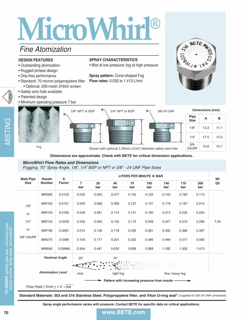
70 www.BETE.com
MISTING
TO O
RD
ER:specify pipe size, connection type,
nozzle num
ber, spray angle, and material.
Fine Atomization
MicroWhirl®
Flow Rate ( l/min ) = K Ö bar
DESIGN FEATURES• Outstanding atomization• Rugged pinless design• Drip-free performance• Standard: 70 micron polypropylene filter • Optional: 200-mesh 316SS screen
• Safety wire hole available• Patented design• Minimum operating pressure 7 bar
SPRAY CHARACTERISTICS• Mist at low pressure; fog at high pressure
Spray pattern: Cone-shaped FogFlow rates: 0.032 to 1.413 L/min
Fog Shown with optional 1.59mm (1/16”) diameter safety wire hole
1/8” NPT or BSP 1/4” NPT or BSP 3/8-24 UNF
Male PipeSize
NozzleNumber
K Factor
LITERS PER MINUTE @ BARWt(g)7
bar20bar
40bar
70bar
100bar
140bar
170bar
200bar
1/8”
or
1/4”
or
3/8”-24UNF
MW085 0.0122 0.032 0.055 0.077 0.102 0.122 0.145 0.160 0.173
7.09
MW105 0.0151 0.040 0.068 0.096 0.127 0.151 0.179 0.197 0.214
MW125 0.0180 0.048 0.081 0.114 0.151 0.180 0.213 0.235 0.255
MW145 0.0209 0.055 0.093 0.132 0.175 0.209 0.247 0.272 0.296
MW195 0.0281 0.074 0.126 0.178 0.235 0.281 0.332 0.366 0.397
MW275 0.0396 0.105 0.177 0.251 0.332 0.396 0.469 0.517 0.560
MW695 0.09988 0.264 0.447 0.632 0.836 0.999 1.182 1.302 1.413
MicroWhirl Flow Rates and DimensionsFogging, 70° Spray Angle, 1/8”, 1/4” BSP or NPT or 3/8” - 24 UNF Pipe Sizes
Standard Materials: 303 and 316 Stainless Steel, Polypropylene filter, and Viton O-ring seal* (*supplied for 3/8”-24 UNF connection)
PipeSize A B
1/8” 12.3 11.1
1/4” 17.5 14.3
3/8-24UNF
10.8 12.7
Dimensions (mm)
Nominal Angle 20° 70°
mist light fog fine, heavy fogAtomization Level
Dimensions are approximate. Check with BETE for critical dimension applications.
Spray angle performance varies with pressure. Contact BETE for specific data on critical applications.
Pattern with increasing pressure from nozzle
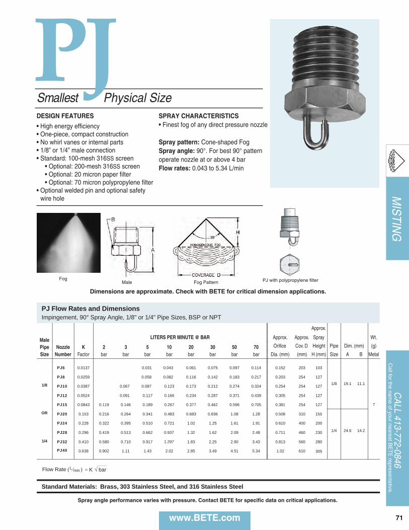
K 1 2 3 5 7 10 20 30 O
) = b
Brass, 303 Stainless Steel, and 316 Stainless Steel
Approx.
Male LITERS PER MINUTE @ BAR Approx. Approx. Spray Wt.
Pipe Nozzle K 2 3 5 10 20 30 50 70 Orifice Cov. D Height Pipe Dim. (mm) (g)
Size Number Factor bar bar bar bar bar bar bar bar Dia. (mm) (mm) H (mm) Size A B Metal
PJ6 0.0137 0.043 0.061 0.075 0.097 0.114 0.152 203 103
1/8 19.1 11.1
7
1/8
PJ8 0.0259 0.058 0.082 0.116 0.142 0.183 0.217 0.203 254 127
PJ10 0.0387 0.067 0.087 0.123 0.173 0.212 0.274 0.324 0.254 254 127
PJ12 0.0524 0.091 0.117 0.166 0.234 0.287 0.371 0.439 0.305 254 127
OR
PJ15 0.0843 0.119 0.146 0.189 0.267 0.377 0.462 0.596 0.705 0.381 254 127
PJ20 0.153 0.216 0.264 0.341 0.483 0.683 0.836 1.08 1.28 0.508 310 155
1/4 24.6 14.2
PJ24 0.228 0.322 0.395 0.510 0.721 1.02 1.25 1.61 1.91 0.610 400 200
1/4
PJ28 0.296 0.419 0.513 0.662 0.937 1.32 1.62 2.09 2.48 0.711 460 230
PJ32 0.410 0.580 0.710 0.917 1.297 1.83 2.25 2.90 3.43 0.813 560 280
PJ40 0.638 0.902 1.11 1.43 2.02 2.85 3.49 4.51 5.34 1.02 610 305
= K √ bar
Standard Materials: Brass, 303 Stainless Steel, and 316 Stainless Steel
0.031
PJ Flow Rates and Dimensions Impingement, 90° Spray Angle, 1/8" or 1/4" Pipe Sizes, BSP or NPT
Flow Rate ( L ⁄min )
Smallest Physical SizeDESIGN FEATURES• High energy efficiency• One-piece, compact construction• No whirl vanes or internal parts • 1/8” or 1/4” male connection• Standard: 100-mesh 316SS screen• Optional: 200-mesh 316SS screen• Optional: 20 micron paper filter• Optional: 70 micron polypropylene filter
• Optional welded pin and optional safetywire hole
SPRAY CHARACTERISTICS• Finest fog of any direct pressure nozzle
Spray pattern: Cone-shaped FogSpray angle: 90°. For best 90° patternoperate nozzle at or above 4 barFlow rates: 0.043 to 5.34 L/min
FogMale Fog Pattern
Dimensions are approximate. Check with BETE for critical dimension applications.
PJ with polypropylene filter
PJ
Spray angle performance varies with pressure. Contact BETE for specific data on critical applications.
MISTIN
G
www.BETE.com
CALL 413-772-0846
Call for the nam
e of your nearest BETE representative.
71

72 www.BETE.com
MISTING
TO O
RD
ER:specify pipe size, connection type,
nozzle num
ber, spray angle, and material.
P
P Flow Rates and Dimensions Cone-Shaped Fog, 90° Spray Angle, 1/4" Pipe Size, BSP or NPT
Approx. Approx.
Male LITERS PER MINUTE @ BAR Approx. Coverage Spray Approx. Wt.
Pipe Nozzle K 1 2 3 5 7 10 20 30 Orifice (mm) Height Dim. (mm) (g)
Size Number Factor bar bar bar bar bar bar bar bar Dia. (mm) D H (mm) A B Metal
1/4
P20 0.153 0.153 0.216 0.264 0.341 0.404 0.483 0.683 0.836 0.508 300 150
46.5 16.0 57
P24 0.228 0.228 0.322 0.395 0.510 0.603 0.721 1.02 1.25 0.610 400 200
P28 0.296 0.296 0.419 0.513 0.662 0.784 0.937 1.32 1.62 0.711 460 230
P32 0.410 0.410 0.580 0.710 0.917 1.09 1.30 1.83 2.25 0.813 560 280
P40 0.638 0.638 0.902 1.11 1.43 1.69 2.02 2.85 3.49 1.02 610 305
P48 0.912 0.912 1.29 1.58 2.04 2.41 2.88 4.08 4.99 1.22 710 355
P54 1.21 1.21 1.71 2.09 2.70 3.20 3.82 5.40 6.62 1.37 760 380
P66 1.71 1.71 2.42 2.96 3.82 4.52 5.40 7.64 9.36 1.68 910 455
P80 2.46 2.46 3.48 4.26 5.50 6.51 7.78 11.0 13.5 2.03 1200 600
P120 5.54 5.54 7.83 9.59 12.4 14.7 17.5 24.8 30.3 3.05 1500 750
Flow Rate ( L ⁄min ) = K √ bar
Standard Materials: Brass, 303 Stainless Steel, and 316 Stainless Steel
A
Cov. D Height Pipe Dim. (mm) (g)
S
= √ b
Brass, 303 Stainless Steel, and 316 Stainless Steel
0
Fine AtomizationDESIGN FEATURES• High energy efficiency• No whirl vanes or internal parts• Highly efficient laminar jet impinges ontarget pin generating fine fog• Male connection
SPRAY CHARACTERISTICS• Finest fog of any direct pressure nozzle
Spray pattern: Cone-shaped FogSpray angle: 90°. For best 90° patternoperate nozzle at or above 4 barFlow rates: 0.153 to 30.3 l/min
FogMale Fog Pattern
Dimensions are approximate. Check with BETE for critical dimension applications.
Spray angle performance varies with pressure. Contact BETE for specific data on critical applications.

MISTIN
G
www.BETE.com
CALL 413-772-0846
Call for the nam
e of your nearest BETE representative.
73
L
L Flow Rates L Dimensions Hollow Cone, 90° Spray Angle, 1/8" and 1/4" Pipe Sizes, BSP or NPT BSP or NPT
High Pressure Operation
Male LITERS PER MINUTE @ BAR recom. for Metal Only Approx. Male Wt.
Pipe Nozzle K 0.7 1 1.5 2 3 4 5 7 Orifice Pipe Dimensions
(mm) (g)
Size Number Factor bar bar bar bar bar bar bar bar Dia. (mm) Size A B D H Metal
1/8 L40 0.638 0.534 0.638 0.781 0.902 1.11 1.28 1.43 1.69 1.02
1/8" 28.4 14.3
610 305
17 L48 0.912 0.76 0.91 1.12 1.29 1.58 1.82 2.04 2.41 1.22 690 345
or L54 1.21 1.01 1.21 1.48 1.71 2.09 2.42 2.70 3.20 1.37 760 380
L66 1.71 1.43 1.71 2.09 2.42 2.96 3.42 3.82 4.52 1.68
1/4" 33.3 14.3
910 455
21 1/4 L80 2.46 2.06 2.46 3.01 3.48 4.26 4.92 5.50 6.51 2.03 1200 600
L120 5.54 4.63 5.54 6.78 7.83 9.59 11.1 12.4 14.7 3.05 1500 750
Flow Rate ( l ⁄min ) = K √ bar
Standard Materials: Brass, 303 Stainless Steel, 316 Stainless Steel, and PTFE (L40, L48, L54 not available in PTFE)
SprayDimensions
(mm)
Low Flow
DESIGN FEATURES• A series of small spiral nozzles with ori-fice diameters of 1.02mm to 3.05mm• Male connection
SPRAY CHARACTERISTICSSpray pattern: Hollow Cone Fog,nearly as fine as P SeriesSpray angles: 90° standard(120° available by special order)Flow rates: 0.534 to14.7 l/min
Hollow Cone 90° Fog Pattern
Metal
Dimensions are approximate. Check with BETE for critical dimension applications.
Spray angle performance varies with pressure. Contact BETE for specific data on critical applications.

NPT LITERS PER HOUR @ BAR Male Pipe Nozzle K 3 5 10 20 70 Size Number Factor bar bar bar bar bar
UML63M 1.44 2.5 3.2 4.6 6.4 12.11/8 UML126M 2.88 5.0 6.4 9.1 12.9 24.1 UML170M 3.89 6.7 8.7 12.3 17.4 32.6
Flow Rate (l/hr) = K Ö bar
Standard Material: Polyacetal
UltiMist Plastic Flow RatesHollow Cone, Medium Spray Angle, 1/8" Pipe Size
NPT, BSP Male or LITERS PER HOUR @ BAR Female Pipe Nozzle K 3 10 40 70 80Size Number Factor bar bar bar bar bar UM37M 0.84 1.5 2.7 5.3 7.1 7.51/8 UM50M 1.14 2.0 3.6 7.2 9.5 10.2 UM75M 1.71 3.0 5.4 10.8 14.3 15.3or UM100M 2.28 3.9 7.2 14.4 19.1 20.4 UM150M 3.42 5.9 10.8 21.6 28.6 30.61/4 UM200M 4.56 7.9 14.4 28.8 38.1 40.8 UM250M 5.70 9.9 18.0 36.0 47.7 51.0 UM300M 6.84 11.8 21.6 43.2 57.2 61.1
Flow Rate (l/hr) = K Ö bar
Standard Material: 416 Stainless Steel Tip, Brass Adapter/Body
Mist
DESIGN FEATURESMetal:· 416 Stainless Steel tip· Brass adapter · 1/8" and 1/4" sizes· Male or female connections· Integral 100 mesh strainerPlastic:· All plastic construction · 1/8" male connection
SPRAY CHARACTERISTICS · Very fine, fog-like mist· Produces high number of droplets under 60 micronsSpray pattern: Hollow Cone Medium angleFlow rates: Metal - (1.5 - 61.1 L/hr) Plastic - (2.5 - 32.6 L/hr)
Misting Nozzles
UltiMist Metal Flow Rates and DimensionsHollow Cone, Medium Spray Angle, 1/8" and 1/4" Pipe Sizes
1.88 [48 mm]
0.75 [19mm] HEX
0.63 [16mm] HEX
Plastic Nozzle
0.86 [22mm]
0.48 [12mm] HEX
Metal
Adapter Strainer Tip
9/16-24 UNEF thread
UltiMist®
Spray angle performance varies with pressure. Contact BETE for specific data on critical applications.
Dimensions are approximate. Check with BETE for critical dimension applications.
Brass 416StainlessSteel
74 www.BETE.com
MISTING
TO O
RD
ER:specify pipe size, connection type,
nozzle num
ber, spray angle, and material.

MISTIN
G
www.BETE.com
CALL 413-772-0846
Call for the nam
e of your nearest BETE representative.
75
SSSmall Droplet Size Dense Fog
DESIGN FEATURES• Multiple flat fan patterns• Solid one-piece construction• Female connection
SPRAY CHARACTERISTICS• Relatively small dropletsSpray pattern: Dense Full ConeFlow rates: 9.16 to 618 l/minSpray angles:SS4.8 thru SS25 - 35°SS35 thru SS70 - 45°
Fog
LITERS PER MINUTE @ BAR Female Pipe Nozzle K 0.7 1 2 3 5 10 15 Dimensions (mm) Wt.Size Number Factor bar bar bar bar bar bar bar A B (g)
SS4.8 10.9 9.16 10.9 15.5 19.0 24.5 34.6 42.4
3/4 SS9 20.5 17.2 20.5 29.0 35.6 45.9 64.9 79.5 25.4 35.1 85.1
SS12 27.4 22.9 27.4 38.7 47.4 61.2 86.5 106
SS18 41.1 34.3 41.1 58.1 71.1 91.8 130 159
SS25 57.0 47.7 57.0 80.6 98.8 127 180 221 26.5 42.2 1421
SS35 79.8 66.8 79.8 113 138 178 252 309
SS50 114 95.4 114 161 198 255 361 442 31.0 53.1 2271 1/4 SS70 160 134 160 226 277 357 505 618
Flow Rate (l/min) = KÖ bar
Standard Materials: Brass, 303, and 316 Stainless Steel.
Dimensions are approximate. Check with BETE for critical dimension applications.
SS Flow Rates and DimensionsFull Cone, 3/4", 1” and 1-1/4" Pipe Size, BSP or NPT
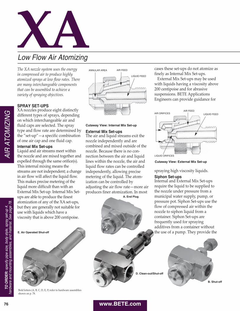
External Mix Set-upsThe air and liquid streams exit thenozzle independently and arecombined and mixed outside of thenozzle. Because there is no con-nection between the air and liquidlines within the nozzle, the air andliquid flow rates can be controlledindependently, allowing precisemetering of the liquid. The atom-ization can be controlled byadjusting the air flow rate—more airproduces finer atomization. In most
XALow Flow Air AtomizingThe XA nozzle system uses the energy in compressed air to produce highlyatomized sprays at low flow rates. Thereare many interchangeable componentsthat can be assembled to achieve avariety of spraying objectives.
SPRAY SET-UPSXA nozzles produce eight distinctlydifferent types of sprays, dependingon which interchangeable air andfluid caps are selected. The spraytype and flow rate are determined bythe ”set-up”—a specific combinationof one air cap and one fluid cap.Internal Mix Set-upsLiquid and air streams meet withinthe nozzle and are mixed together andexpelled through the same orifice(s).This internal mixing means thestreams are not independent; a changein air flow will affect the liquid flow.This makes precise metering of theliquid more difficult than with anExternal Mix Set-up. Internal Mix Set-ups are able to produce the finestatomization of any of the XA set-ups,but they are generally not suitable foruse with liquids which have aviscosity that is above 200 centipoise.
cases these set-ups do not atomize asfinely as Internal Mix Set-ups.External Mix Set-ups may be usedwith liquids having a viscosity above200 centipoise and for abrasivesuspensions. BETE ApplicationsEngineers can provide guidance for
spraying high viscosity liquids.Siphon Set-upsInternal and External Mix Set-upsrequire the liquid to be supplied tothe nozzle under pressure from amunicipal water supply, pump, orpressure pot. Siphon Set-ups use theflow of compressed air within thenozzle to siphon liquid from acontainer. Siphon Set-ups arefrequently used for sprayingadditives from a container withoutthe use of a pump. They provide the
Cutaway View: Internal Mix Set-up
Cutaway View: External Mix Set-up
E. Air Operated Shut-off
A. End Plug
Bold letters (A, B, C, D, E, F) refer to hardware assembliesshown on p. 78.
D. Clean-out/Shut-off
B. Shut-off
ANNULAR AREA AIR FEED
LIQUID FEED
AIR FEEDLIQUID FEEDAIR ORIFICES
LIQUID ORIFICES
www.BETE.com76
AIR ATO
MIZING
TO O
RD
ER:specify pipe size, body style, spray set-up #,
hardware and mounting assemblies, and material. See page 78.

XW Air Cap
XA 01/02 Bodywith E or FHardware
A. Plug. The minimum optionhardware assembly required for XAoperation. Provides neither clean-outnor shut-off.B. Shut-off. Turning the knurledknob will stop the flow of liquid tothe nozzle. Should not be used tometer the flow of liquid.C. Clean-out. Pressing the spring-loaded plunger will force a smalldia-meter rod through the liquidorifice, cleaning any obstruction.Useful for intermittent spraying of aliquid that may dry in the orificewhen not in use.
D. Clean-out/Shut-off. Combinesfunctions of hardware assemblies Band C in one unit.
lowest flow rates available in the XAseries (as low as 0.38 L/hr). They aregenerally not suitable for use withliquids having a viscosity above 200centipoise.By supplying the liquid underpressure, SR Set-ups may be usedwith liquids having a viscosity above200 centipoise. In this case, the liquidflow rate is regulated by the fluidcap, and can be determined by usingthe EF chart for the specific fluid cap.
The basic XA nozzle assemblyconsists of a body, a spray set-up,and a “hardware assembly” that canprovide shut-off and clean-outcapabilities.
The XA00 Square Body is the basiccomponent of a non-automatic XAnozzle. Air and liquid feeds arelocated at opposite ends, perpendi-cular to the spray.The XA03 Body has air and liquidfeeds on one side, perpendicular tothe spray axis.The XA05 Body has air and liquidinlets located in-line with the spray.Hardware assemblies cannot be usedwith the XA05 body.
PF Air Cap
XA05 Body
XA03 Body
XA00 Body
with C Hardware
Fluid Cap
FF Air Cap
SR Air Cap
PR Air Cap
BASIC OPERATION
Non-Automatic Operation
Hardware Assemblies for Non-Automatic Operation
XA Components & Options
EF Air CapER Air Cap CALL 413-772-0846
Call for the nam
e of your nearest BE
TE
representative.
77
AIR ATO
MIZIN
G
www.BETE.com

www.BETE.com78
AIR ATO
MIZING
TO O
RD
ER:specify pipe size, body style, spray set-up #,
hardware and mounting assemblies, and material. See page 78.
XA Components & OptionsSpray Set-upSpray Set-up Body Styles and SealsBody Styles and Seals Hardware AssembliesHardware Assemblies
ER
SF
SR
PR
PF
AD
EF
FF
XW
Fluid Cap
Front Gasket
Air CapsXA 00 - Standard
Rear Gasket
Rear Gaskets
Replaceable E orF Tip Assembly
A End Plug
B Shut-off
C** Clean-out
D** Clean-out/Shut-off
E Air-operated Shut-off
F** Air-operated Clean-out/Shut-off
Adapter
ReplaceableE or F TipAssembly
Rear Gasket
Seal Kit: 39572
Bushing
Large O-rings
MountingBracket
Thin Wall MountLock Nut Thick & Thin Wall
Mounting Adapter
Thin WallMounting Gasket
Replaceable Components and Gaskets
Seal KitFront GasketRear GasketBody SealCap NutAdapter
Thick & Thin Wall MountAdapterThin Wall Lock NutThin Wall Mounting GasketMounting Bracket
E - Replacement TipF - Replacement Tip**
**Specify fluid cap
Spray Set-up Number
Sizes and Series1/8”B, 1/4”B, 1/2”B - BSP 1/8”, 1/4”, 1/2” - NPT
Body Styles00 01 02 03 05 06 07 08 10 11 12
Air Cap StylePR FF AD XW PF EF SR SF ER
Mounting Hardware01 02 03
Extension Size*12”
Hardware AssembliesA B C D E F
Combination Number
1/4 XA 01 PR 250 E 01 12
TO ORDER
XA 08 - Directional spray, 2 nozzle spray set-ups
XA 06(4-5 spray setups)Parallel inletsXA 05 - Spray
parallel to parallel inlets
XA 03 - Spray perpendicular to parallel inlets
XA 01
XA 02
*For extensions, A hardware isstandard; E and F hardware maybe provided on an application-specific basis.
XA 12 Spray parallel to parallelinlets. With mounting holes.
XA 10/11 Bodies:Low profile, built-in cylinderXA10 – Separate atomizingand cylinder air inletsXA11 – Combined atomizingand cylinder air inlet
XA 07 - Sprayperpendicular to1/8” parallel inlets
XA 10
XA 11
E
F
E
F

For critical applications whichrequire automatic, no-drip, or high-speed spray shut-off, the XA can besupplied with an air-cylinder-operated shut-off or clean-out/shut-off. These air cylinders provide virtu-ally instantaneous liquid shut-off atrates of up to 180 cycles per minute.The air cylinders require a minimum of5.5 bar to run that fast.
The XA01, XA02, XA10, and XA11Round Bodies are rugged, highlyreliable, and well-suited to the rigorsof high-cycle automatic operation.They have been designed to simplifythe feed piping required forinstalling automatic nozzles byproviding a constant location for theair inlet piping. With their neat,professional appearance, they areparticularly recommended for OEMapplications.The XA01 Round Body has oneinlet for air and one for liquid. Be-cause the air inlet supplies air forboth cylinder movement and liquidatomization, spraying during start-up and shut-off is not as crisp andprecise as with the XA02. The XA01body cannot be used with atomizing airpressure under 2 bar.The XA02 Round Body has twoinlets for air and one inlet for liquid.One of the air inlets supplies thecylinder and the other supplies
atomizing air. The XA02 bodymust be used when the air cylinderoperates at a different pressure fromthe atomizing air or where theatomizing air is supplied below 2 bar.NOTE: The XA00 Square and XA03Bodies used for non-automatic operationcan also be used, with hardware assem-blies E or F, for automatic operation.Special design features allow fieldupgrading to automatic operation. The XA10 and XA11 Bodies have abuilt in air-operated cylinder. The integral cylinder provides asmaller profile for use where space is limited.
E. Air-Operated Shut-off. Removalof air pressure to the cylinder causesa spring-loaded poppet valve actua-tor to shut off liquid flow.F. Air-Operated Clean-out/Shut-off.Operation similar to E, but includesa clean-out needle.
Electrically operated solenoid valvescan be used to control the operationof any XA nozzle. BETE can supplysolenoid valves matched to yourspecific application.
A 3-way, quick-exhaust solenoidvalve is required to operate the E orF hardware assembly. The valve is
located in the line that supplies air tothe cylinder, as close to the nozzle aspossible. Independent control of theatomizing air of an XA02 or squarebody requires an additional 2-waysolenoid valve.
Two-way solenoid valves can beused to stop and start the flow of airand liquid to any non-automatic XA nozzle.
For optimum reliability, every XAnozzle should have a strainer andregulator in the liquid feed line and afilter and regulator in the air feedline. Every XA nozzle with a SiphonFeed Set-up should have a filter andregulator in the air line. The size andtype of each of these componentsdepends on the application, and canbe determined by your BETE salesrepresentative. BETE maintains aninventory of filters, strainers, andregulators that can be supplied withyour XA nozzle to ensure reliableoperation. These components can be purchased individually or in kit form.
XA Components & Options
Simple piping and robust design describe this multiple nozzle XA lance.
Corrosion-resistant XA in PVC
AUTOMATIC OPERATION
Bodies for Automatic Operation
Hardware Assemblies for Automatic Operation
SOLENOID VALVES
Solenoids for Automatic XA Nozzles.
Solenoids for Non-Automatic XA Nozzles.
FILTERS, REGULATORS AND STRAINERS
The XA06 manifold body can befitted with up to five nozzlesetups and is often used forhumidification of large areas.
CALL 413-772-0846
Call for the nam
e of your nearest BE
TE
representative.
79
AIR ATO
MIZIN
G
www.BETE.com

The spray set-up can be moved awayfrom the nozzle body by usingoptional 152mm or 305mmextensions. These allow the spray tobe moved closer to the target whilekeeping the nozzle body andassociated piping at a distance.
In many XA installations the nozzleis supported by the rigid metal pipethat supplies air or liquid. There areseveral components which canprovide support for the XA Bodieswhen it isn’t appropriate to suspendthe nozzle from piping; for example,when the nozzle will spray throughthe wall of a tank or duct, or whenthe air and liquid will be suppliedthrough flexible tubing. All XAbodies except the XA03 can be usedwith any of the mounting hardwaredescribed here.
Three-piece adapter used to supportan XA nozzle with the body locatedoutside a tank or duct having arelatively thin (less than 10mm) walland the spray directed into theinterior. To use this adapter, a 27mmdiameter hole must be drilledthrough the wall. This adapter bothsecures the air cap and attaches thenozzle body to the tank wall.
Similar in design and function to theThin Wall Adapter, but intended foruse with tanks or ducts with wallsthat are thick enough (10mm orover) to be drilled and tapped for a3/4” NPT thread.
This bracket is used in combinationwith a Thin Wall Adapter to supportan XA nozzle from a 13mm-diametermetal rod. The bracket allowsflexibility in aiming the spray.
The standard materials for the XAseries are nickel-plated brass and303 and 316 stainless steels. Othermetals and plastics can be suppliedon request. See page 12 for acomplete material list.
The air cylinders used for XAhardware assemblies E and F haverods and cylinders made of stainlesssteel and end caps made ofanodized aluminum. All metalparts in contact with the sprayliquid are 316 stainless steel.
The standard material for XAgaskets is compressed fiber with aneoprene binder. For installationsrequiring FDA approval, SBRgaskets are available. Otherelastomeric and metallic gasketmaterials can be supplied onrequest.The standard material for O-ringsin XA automatics is Viton®. Othermaterials available on request.
XA Components & Options
XA02 with Thin Wall 02 Adapter
XA02 with Thick Wall 01 Adapter
XA03 MountingBracket
SPRAY EXTENSIONS
MOUNTING HARDWARE
Thin Wall 02 Adapter
Thick Wall 01 Adapter
Mounting Bracket 03 Adapter
MATERIALSBodies, Fluid Caps, Air Caps,Hardware Assemblies, MountingHardware
Air Cylinders
Seals
2XA9890Gasket
2XA9886B - 3/4” BSP2XA9886 - 3/4” NPT
2XA9889Locking nut
Minimum wall thickness
BETE can fabricate XA nozzlesinto any number of lanceassembly variations
Automatic XA nozzles in amanifold configuration used forcoating a very wide product
Spray lance (see pages 18, 19) with a right angle XA and quick-connect fittings
www.BETE.com80
AIR ATO
MIZING
TO O
RD
ER:specify pipe size, body style, spray set-up #,
hardware and mounting assemblies, and material. See page 78.

66.7mmMAX.
54mmMAX.
41.3mm
Overall Dimensionsfor Assemblies with
XA03 Bodies
Overall Dimensions for Assemblies with
XA05 Bodies
Ø 41.3mm
Spray Set-up Numbers
PIPESPRAYSIZE SET-UP FLUID AIR
BSP or NPT NO. CAP CAP
EF
EF 050 AC1001EF 100
FC7AC1003
EF 150 FC4 AC1001
1/8
OR
1/4
EF 200 AC1003EF 250
FC3AC1001
EF 300 AC1003
FLATFAN
(EXTERNALMIX)
EF 350 FC6 AC1002EF 400 AC1004EF 450 FC2 AC1002EF 500 AC1004EF 550 FC1 AC1002EF 600 AC1004EF 650 FC8 AC1005EF 700 FC9 AC1005EF 750 FC5 AC1005
1/2 EF 5050 FC501 AC5001
SFSIPHON
FLATFAN
1/8OR1/4
SF 050 FC3 AC1101SF 100 FC6 AC1102
SF 150 FC2 AC1103SF 200 FC2 AC1104
SR
SR 050 FC7 AC1201
1/8OR1/4
SR 150 FC4 AC1201
SIPHONROUND
SR 200 FC4 AC1202SR 250 FC3 AC1202SR 400 FC1 AC1204SR 450 FC5 AC1205
1/2 SR 5050 FC501 AC5201
PF
PF 050 FC4 AC1301PF 100 FC3 AC1303
1/8OR1/4
PF 150 FC3 AC1301
PRESSUREFLATFAN
PF 200 FC3 AC1302PF 250 FC2 AC1304PF 300 FC1 AC1304PF 350 FC1 AC1305PF 400 FC5 AC1306
1/2 PF 5050 FC501 AC5301PF 5100 FC502 AC5302
XWEXTRA
WIDE-ANGLEROUND
1/8 OR 1/4 XW 050 FC8 AC1401
1/2 XW 5050 FC502 AC5401
PR
PR 050 FC4 AC15011/8OR1/4
PR 100 FC4 AC1502PR 150 FC3 AC1502
PRESSURE ROUND
PR 200 FC2 AC1503PR 250 FC1 AC1503PR 300 FC5 AC1504
1/2PR 5050 FC501 AC5501PR 5100 FC502 AC5502
AD
AD 050 FC4 AC1601AD 100 FC2 AC1603AD 150 FC2 AC1602
WIDEANGLEROUND
AD 200 FC1 AC1603AD 250 FC1 AC1604AD 300 FC5 AC1605AD 5050 FC501 AC5601AD 5100 FC501 AC5602AD 5150 FC501 AC5603AD 5200 FC502 AC5604
FF DEFLECTEDFLAT FAN 1/8 OR 1/4 FF 050 FC10 AC1701
1/8OR1/4
SET-UP
1/2
ER NARROWANGLEROUND
ER 050 FC7AC1801ER 150 FC4
ER 250 FC31/8OR1/4
ER 350 FC6AC1802ER 450 FC2
ER 550 FC1ER 650 FC3
AC1803ER 750 FC9ER 850 FC5
XA Components & Options
Overall Dimensions of XA Assemblies with XA00 Body (Shown with E or FHardware)
Dimensions with Hardware Options for XA00 Body, BSP or NPT
Pipe
Size
Hardware
Option
W X Y Max. "Z"
A
1/8 B
OR C
1/4 D
E
F
1/2 A
Dimensions in (mm)
22.2 42.9 49.2
31.8 63.5 68.3 25.4
14.3
42.3
63.5
77.0
103
103
X
W
ZYMAX.
Ø 41mm
120mm49mmMAX.
CENTERLINE FORAIR & LIQUID INLETS
CALL 413-772-0846
Call for the nam
e of your nearest BE
TE
representative.
81
AIR ATO
MIZIN
G
www.BETE.com

XA Components & Options
BETE carries a complete line ofcontrols and accessories requir-ed for setting up a system usingthe XA Series nozzles.Contact your BETE representative for details.
In a pressure-fed system, theliquid is supplied under pressureto either internal or external mixBETE XA Series nozzles.Air and liquid regulatorscontrol the fluid delivery pressure, while the air filter and liquid strainer ensure thatthe supplied fluids are of high quality.Operational control is main-tained by manual or solenoidvalves used in conjunction withthe various hardware assemblies.
In a siphon-fed system, theliquid is supplied by either asiphon or gravity feed.An air regulator controls the airdelivery pressure, while the airfilter ensures that thecompressed air is of high quality.Operational control is main-tained by manual or solenoidvalves used in conjunction withthe various hardware assemblies.When used as a gravity feedset-up, a positive liquid shutoffcapability should be provided.Filters, regulators, and strainersmatched to your XA applicationare available from stock.
SYSTEM SET-UPS ANDACCESSORIES
Pressure System Set-up
Siphon System Set-up
SIPHON SYSTEM
PRESSURE SYSTEM
www.BETE.com82
AIR ATO
MIZING
TO O
RD
ER:specify pipe size, body style, spray set-up #,
hardware and mounting assemblies, and material. See page 78.

CALL 413-772-0846
Call for the nam
e of your nearest BE
TE
representative.
83
AIR ATO
MIZIN
G
www.BETE.com
XAAD
XA AD Set-up Flow Rates and DimensionsPressure-fed, Internal Mix, Wide Angle Round Spray Pattern, 1/8" and 1/4" Pipe Sizes, BSP or NP T
Fluid 0.7 Bar Liquid 1.5 Bar Liquid 2.0 Bar Liquid 3.0 Bar Liquid 4.0 Bar Liquid Spray Dimensions Spray and Nm 3
h Nm 3
h Nm 3
h Nm 3
h Nm 3
h Pipe Set-up Air Cap Air l/h Air l/h Air l/h Air l/h Air l/h Bar A B C D Size Number Numbers (bar) (bar) (bar) (bar) (bar) air liquid (mm) (mm) (mm) (m)
0.6 5.3 0.60 1.1 8.1 0.79 1.5 8.1 0.92 2.4 8.9 1.24 3.1 10.5 1.44 0.7 0.7 140 180 230 1.5
AD 050
Fluid Cap 0.7 4.3 0.72 1.3 7.0 0.88 1.8 6.6 1.09 2.7 8.1 1.40 3.4 9.7 1.68 1.4 1.5 150 190 240 1.8 FC4 0.9 3.0 0.84 1.4 6.4 0.94 2.1 4.9 1.32 3.0 6.4 1.66 3.9 7.8 2.16 1.8 2.0 160 200 250 2.1
& 1.0 1.7 1.02 1.5 5.5 1.01 2.4 3.2 1.68 3.2 4.9 1.92 4.2 6.1 2.52 3.0 3.0 160 200 260 2.7 Air Cap 1.7 4.5 1.16 3.4 4.2 2.13 4.6 4.4 2.82 3.9 4.0 190 230 300 4.0 AC1601 1.8 3.5 1.30 3.5 3.4 2.33 4.9 2.8 3.24
0.9 7.0 3.00 1.7 13.2 4.08 2.0 18.5 4.08 2.8 25.0 5.04 3.7 31.0 5.76
AD 100
Fluid Cap 1.0 2.1 3.72 1.8 9.8 4.74 2.1 15.1 4.56 3.0 22.0 5.52 3.8 28.0 6.30 FC2 2.2 11.7 5.10 3.1 18.5 6.06 3.9 26.0 6.78 0.9 0.7 180 240 310 1.8
& 3.2 15.1 6.54 4.1 23.0 7.32 1.7 1.5 190 250 330 2.4 Air Cap 3.4 12.1 7.14 4.2 20.0 7.80 2.1 2.0 190 250 330 3.2 AC1603 3.5 9.1 7.80 4.6 13.6 9.18 3.2 3.0 200 260 340 4.1
3.7 6.1 8.52 4.9 6.8 11.0 4.1 4.0 210 280 370 5.9
1.1 12.3 2.40 2.2 16.3 3.72 2.7 21.0 4.14 4.2 19.3 6.00 5.6 22.0 7.80
AD 150
Fluid Cap 1.3 9.9 2.70 2.5 12.1 4.26 3.0 16.3 4.68 4.6 14.6 6.78 6.0 17.6 8.52 FC2 1.4 7.9 3.00 2.8 8.9 4.74 3.2 12.3 5.16 4.9 10.8 7.44 6.3 14.0 9.12 1.5 0.7 150 190 230 2.7
& 1.5 6.1 3.24 3.0 7.6 4.98 3.4 10.7 5.46 5.3 8.1 8.10 6.7 11.4 9.78 3.0 1.5 160 200 240 4.6 Air Cap 1.7 4.9 3.48 3.1 6.4 5.22 3.5 9.3 5.64 5.6 6.2 8.76 7.0 9.1 10.4 3.4 2.0 160 200 240 5.5
1/8 AC1602 1.8 3.9 3.72 3.2 5.5 5.46 3.9 6.4 6.30 6.0 4.9 9.42 5.3 3.0 180 220 250 7.3 2.0 3.1 4.02 3.4 4.7 5.70 4.2 4.7 6.90 6.3 4.0 10.0 6.3 4.0 190 240 280 9.4
OR 0.7 23.1 1.70 1.4 37.1 2.38 2.1 26.9 3.91 2.8 49.2 3.91 3.7 57.2 4.59
AD 200
Fluid Cap 0.9 8.30 2.89 1.5 30.3 2.89 2.2 22.3 4.42 3.0 40.1 4.59 3.8 53.0 5.10FC1 1.0 3.40 3.40 1.7 18.2 3.74 2.4 11.4 5.44 3.1 32.9 5.10 4.0 44.7 5.95 0.9 0.7 190 250 360 2.1
1/4 & 1.8 11.7 4.42 2.5 7.20 5.95 3.2 28.8 5.44 4.2 34.4 6.80 1.5 1.5 200 270 370 3.2 Air Cap 3.4 20.1 6.63 4.6 18.9 8.83 2.4 2.0 200 270 370 4.1 AC1603 3.5 15.5 7.14 4.9 7.90 10.7 3.2 3.0 200 280 380 5.0
3.7 7.60 8.33 3.9 4.0 200 280 390 6.8
1.3 26.1 5.27 2.1 45.0 7.14 3.1 42.4 10.0 4.2 55.6 11.8 5.6 59.8 14.7
AD 250
Fluid Cap 1.5 21.2 5.95 2.4 38.6 8.16 3.2 40.1 10.7 4.9 42.0 13.8 6.0 52.4 15.6 FC1 1.8 13.6 7.14 2.7 30.7 9.17 3.4 35.6 11.0 5.6 28.4 15.9 6.3 46.8 16.8 2.0 0.7 200 250 330 5.5
& 2.0 9.50 7.82 3.0 23.8 10.2 3.5 33.3 11.2 6.0 20.6 17.1 6.7 39.4 17.7 3.0 1.5 200 270 340 6.4 Air Cap 2.1 7.60 8.16 3.2 19.3 10.9 3.9 24.6 12.6 6.3 14.8 18.0 7.0 33.9 18.9 3.9 2.0 220 280 370 8.2 AC1604 2.3 4.20 8.83 3.5 12.9 11.9 4.6 11.0 15.0 6.7 7.00 19.2 6.0 3.0 230 290 380 9.1
2.4 2.60 9.17 4.2 1.50 14.1 4.9 6.40 16.0 7.0 1.20 20.1 6.3 4.0 240 320 400 10.4
1.7 25.0 9.36 3.0 39.0 13.8 3.4 50.0 15.0 4.6 62.0 19.2 6.0 93.0 23.7
AD 300
Fluid Cap 1.8 19.7 10.0 3.1 33.0 14.4 3.5 43.0 15.6 4.9 47.0 20.7 6.3 77.0 25.5 2.0 0.7 240 330 460 5.5 FC5 2.0 15.1 10.7 3.2 27.0 15.3 3.7 41.0 16.5 5.3 36.0 22.5 6.7 62.0 27.6 3.2 1.5 250 340 470 6.4
& 2.1 11.4 11.6 3.4 23.0 15.9 3.9 27.0 18.0 5.6 26.0 24.3 7.0 52.0 29.7 3.9 2.0 280 370 510 7.3 Air Cap 2.3 7.6 12.3 3.5 18.5 16.8 4.1 23.0 18.6 6.0 18.9 26.1 5.3 3.0 290 380 530 7.9 AC1605 3.7 14.8 17.4 4.2 18.9 19.2 6.3 13.6 27.6 6.3 4.0 330 420 580 9.8
4.4 15.9 20.1
Standard Materials: Nickel-plated Brass, 303 Stainless Steel, and 316 Stainless Steel
3
Pressure-fed/Int. Mix/Wide Angle Round
• 70° Hollow Cone spray pattern• Moderate forward spray projection
DESIGN/SPRAY CHARACTERISTICS• Internal mix• Very fine atomization
1/4” XA AD100 CXA 00 Body; C Hardware
150mm230mm
380mm
Dimensions are approximate. Check with BETE for critical dimension applications.

www.BETE.com84
AIR ATO
MIZING
TO O
RD
ER:specify pipe size, body style, spray set-up #,
hardware and mounting assemblies, and material. See page 78.
XAPR
XA PR Set-up Flow Rates and DimensionsPressure-fed, Internal Mix, Round Spray Pattern, 1/8" and 1/4" Pipe Sizes, BSP or NPT
Fluid 0.7 Bar Liquid 1.5 Bar Liquid 2.0 Bar Liquid 3.0 Bar Liquid 4.0 Bar Liquid Spray Dimensions Spray and
Nm 3
h Nm 3
h Nm 3
h Nm 3
h Nm 3
h Pipe Set-up Air Cap Air l/h Air l/h Air l/h Air l/h Air l/h Bar
Spray B D
Size Number Numbers (bar) (bar) (bar) (bar) (bar) air liquid (deg.) (mm) (m)
0.7 2.5 0.960 1.1 6.4 0.720 1.4 6.4 0.840 2.7 6.2 1.38 3.5 7.8 1.68
PR 050
Fluid Cap 0.9 1.8 1.14 1.4 5.0 0.900 1.7 5.5 1.02 2.8 5.7 1.50 3.7 7.3 1.74 0.9 0.7 13 300 3 FC4 1.0 1.4 1.32 1.7 4.1 1.14 2.0 4.5 1.20 3.0 5.2 1.62 3.9 6.4 1.98 1.7 1.5 13 330 3
& 1.8 3.4 1.20 2.2 3.4 1.44 3.1 4.7 1.74 4.2 5.5 2.28 2.5 2.0 13 360 3 Air Cap 2.0 3.0 1.38 2.4 3.0 1.56 3.2 4.3 1.86 4.5 4.5 2.58 3.1 3.0 14 390 4 AC1501 2.1 2.6 1.50 2.5 2.5 1.68 3.4 3.9 1.98 4.6 4.1 2.70 4.5 4.0 15 440 4
2.2 2.0 1.62 2.7 2.3 1.86 3.7 3.0 2.28 4.8 3.7 2.82
0.7 2.5 1.14 1.4 5.7 1.62 1.7 6.7 1.74 2.2 9.2 2.04 2.8 11.9 2.34
PR 100
Fluid Cap 0.9 2.0 1.32 1.5 5.2 1.74 1.8 6.4 1.86 2.5 8.2 2.34 3.1 11.0 2.58 0.9 0.7 12 430 4 FC4 1.0 1.6 1.56 1.7 4.8 1.92 2.0 5.9 2.04 2.8 7.2 2.64 3.4 10.1 2.82 1.5 1.5 13 460 4
& 1.8 4.3 2.10 2.1 5.2 2.22 3.0 6.7 2.82 3.7 9.2 3.12 2.4 2.0 13 480 4 Air Cap 2.0 3.9 2.22 2.2 4.8 2.40 3.1 6.3 2.94 3.9 8.4 3.48 3.0 3.0 13 510 5 AC1502 2.1 3.4 2.40 2.4 4.3 2.58 3.2 5.9 3.12 4.2 7.6 3.72 3.9 4.0 15 560 5
2.7 3.6 2.88 3.4 5.5 3.30 4.5 6.8 4.08
0.9 4.8 1.26 1.7 8.4 1.86 2.0 10.7 1.98 2.7 16.5 2.22 3.4 20.0 2.58
PR 150
Fluid Cap 1.1 4.1 1.62 1.8 7.5 2.10 2.1 9.8 2.22 2.8 15.4 2.28 3.7 18.4 2.82 1.5 0.7 12 480 4 FC3 1.4 3.4 1.98 2.0 7.0 2.22 2.4 8.2 2.52 3.1 13.6 2.58 3.9 16.8 3.00 2.5 1.5 13 510 4
& 1.5 3.1 2.10 2.2 5.7 2.64 2.7 6.8 2.88 3.4 11.8 2.94 4.2 15.2 3.30 3.0 2.0 13 530 5 1/8 Air Cap 1.7 3.0 2.34 2.5 4.8 2.94 3.0 5.9 3.30 3.7 10.4 3.30 4.5 13.8 3.60 3.4 3.0 14 560 5
AC1502 1.8 2.9 2.46 2.8 4.1 3.24 3.2 5.0 3.54 3.9 9.1 3.66 4.8 12.4 3.90 4.2 4.0 15 600 5 2.0 2.8 2.64 3.1 3.6 3.54 3.5 4.1 3.90 4.2 7.9 3.90 4.9 11.8 4.08
OR 1.1 13.0 4.56 2.2 17.8 6.96 2.8 20.0 8.16 3.4 32.0 8.94 4.6 37.0 11.6
PR 200
Fluid Cap 1.4 8.9 5.46 2.5 13.1 7.80 3.1 16.3 8.94 3.9 25.0 10.2 5.3 29.0 13.2 1.7 0.7 18 660 5 1/4 FC2 1.5 7.2 5.88 2.8 9.5 8.58 3.4 11.9 9.78 4.6 15.9 12.3 5.6 25.0 14.1 2.8 1.5 20 760 6
& 1.7 5.8 6.30 3.1 7.0 9.42 3.9 7.0 11.2 5.3 9.1 14.4 6.0 21.0 15.0 3.9 2.0 20 810 7 Air Cap 1.8 4.7 6.72 3.4 4.9 10.3 4.2 4.7 12.3 5.6 6.8 15.3 6.3 17.4 16.2 5.3 3.0 21 910 8 AC1503 2.0 3.6 7.14 3.5 4.2 10.7 4.6 3.0 13.2 6.0 5.0 16.5 6.7 14.0 17.4 6.0 4.0 21 970 9
2.1 2.7 7.62 6.3 3.6 17.4 7.0 11.0 18.3
0.9 31.0 3.42 1.4 61.0 4.14 2.1 53.0 5.76 2.7 80.0 6.18 3.8 88.0 8.10
PR 250
Fluid Cap 1.0 25.0 3.96 1.5 54.0 4.56 2.4 41.0 6.72 3.0 69.0 7.02 4.2 73.0 9.36 1.0 0.7 17 610 5 FC1 1.1 18.5 4.50 1.7 48.0 5.10 2.7 31.0 7.62 3.2 59.0 7.80 4.6 61.0 10.6 1.8 1.5 18 690 6
& 1.3 12.9 5.10 1.8 41.0 5.58 2.8 26.0 8.16 3.5 49.0 8.76 4.9 48.0 11.8 2.8 2.0 20 760 7 Air Cap 2.0 35.0 6.12 3.0 22.0 8.64 3.7 44.0 9.24 5.3 39.0 12.9 3.5 3.0 20 790 7 AC1503 2.1 30.0 6.60 3.8 37.0 9.66 5.6 31.0 14.4 4.9 4.0 21 910 9
2.2 25.0 7.14 3.9 35.0 10.2 6.0 23.0 15.6
1.0 44.0 5.16 1.4 125 4.74 2.0 123 6.48 2.2 199 5.28 3.0 250 5.94
PR 300
Fluid Cap 1.1 32.0 6.12 1.5 106 5.46 2.1 108 7.14 2.5 174 6.60 3.2 225 7.20 1.0 0.7 19 890 6 FC5 1.7 87.0 6.30 2.2 95.0 7.80 2.8 146 7.98 3.5 205 8.46 1.7 1.5 20 990 7
& 1.8 70.0 7.08 2.4 79.0 8.58 3.1 121 9.24 3.8 182 9.78 2.4 2.0 21 1040 8 Air Cap 2.0 55.0 7.80 2.5 64.0 9.30 3.2 108 9.96 4.1 159 11.0 3.1 3.0 21 1070 8 AC1504 2.7 52.0 9.96 3.4 95.0 10.6 4.6 121 13.5 3.8 4.0 22 1170 9
2.8 42.0 10.7 3.5 84.0 11.2 4.9 93.0 15.3
Standard Materials: Nickel-plated Brass, 303 Stainless Steel, and 316 Stainless Steel
Angle
Pressure-fed/Int. Mix/Narrow Angle RoundDESIGN/SPRAY CHARACTERISTICS• Internal mix• Very fine atomization• Narrow spray angle (12°- 22°)
• Full cone pattern• Large forward projection (up to 8.5 m)
1/4” XA 02 PR050 EXA 02 Body; E Hardware
Dimensions are approximate. Check with BETE for critical dimension applications.

CALL 413-772-0846
Call for the nam
e of your nearest BE
TE
representative.
85
AIR ATO
MIZIN
G
www.BETE.com
XAPF
XA PF Set-up Flow Rates and DimensionsPressure-fed, Internal Mix, Flat Spray Pattern, 1/8" and 1/4" Pipe Sizes, BSP or NPT
Fluid 0.7 Bar Liquid 1.5 Bar Liquid 2.0 Bar Liquid 3.0 Bar Liquid 4.0 Bar Liquid Spray Dimensions Spray and Nm 3
h Nm 3
h Nm 3
h Nm 3
h Nm 3
h Pipe Set-up Air Cap Air l/h Air l/h Air l/h Air l/h Air l/h
Bar A B C D Size Number Numbers (bar) (bar) (bar) (bar) (bar) air liquid (mm) (mm) (mm) (m)
0.7 5.5 1.44 1.3 9.1 1.86 2.0 8.6 2.52 2.7 11.2 3.12 3.9 12.0 4.14
PF 050
Fluid Cap 0.9 4.7 1.62 1.5 7.7 2.16 2.2 7.5 2.82 3.0 10.1 3.36 4.6 9.7 4.86 1.1 0.7 250 360 460 2.6 FC4 1.0 4.1 1.86 1.8 6.5 2.52 2.5 6.2 3.12 3.2 9.1 3.72 5.3 7.5 5.58 2.1 1.5 360 480 660 3.0
& 1.1 3.5 2.04 2.1 5.4 2.82 2.8 5.2 3.42 3.5 8.1 3.96 6.0 5.3 6.24 2.8 2.0 380 530 760 3.2 Air Cap 1.3 3.0 2.22 2.4 4.3 3.12 3.1 4.2 3.78 4.2 5.4 4.74 6.3 4.3 6.60 3.5 3.0 470 610 860 3.4 AC1301 1.4 2.5 2.40 2.7 3.3 3.42 3.2 3.7 3.90 4.6 4.2 5.10 6.7 3.3 6.96 6.0 4.0 560 740 940 4.0
1.5 2.0 2.64 2.8 2.8 3.60 3.4 3.2 4.08 4.9 3.1 5.46 7.0 2.4 7.32 1.3 3.9 1.80 2.1 7.4 2.40 3.0 6.1 3.12 3.9 9.4 3.60 5.3 10.2 4.68
PF 100
Fluid Cap 1.4 3.0 1.98 2.4 5.3 2.70 3.1 5.3 3.24 4.2 7.2 4.02 5.6 8.3 5.04 1.5 0.7 250 330 460 1.8 FC3 1.5 2.3 2.10 2.5 4.4 2.82 3.2 4.5 3.42 4.6 5.3 4.38 6.0 6.6 5.34 2.7 1.5 360 510 690 2.0
& 1.7 1.8 2.28 2.7 3.7 3.00 3.4 3.8 3.54 4.9 3.8 4.80 6.3 5.1 5.88 3.2 2.0 480 580 740 2.0 Air Cap 1.8 1.3 2.46 2.8 3.1 3.12 3.5 3.2 3.72 4.2 3.0 610 740 940 2.1 AC1303 2.0 1.0 2.64 3.0 2.6 3.30 3.9 1.8 4.08 5.6 4.0 640 760 970 2.3
3.1 2.1 3.42 0.9 8.2 1.20 1.4 14.4 1.62 2.1 13.5 2.16 2.7 19.1 2.52 4.6 16.1 4.14
PF 150
Fluid Cap 1.0 6.8 1.38 1.7 11.9 1.92 2.4 11.4 2.52 3.0 17.1 2.76 4.9 13.8 4.56 1.1 0.7 360 460 710 2.1 FC3 1.1 5.5 1.62 2.0 9.5 2.22 2.7 9.2 2.82 3.2 15.1 3.12 5.3 11.5 4.98 2.1 1.5 430 610 810 2.4
& 1.3 4.1 1.80 2.1 8.3 2.40 3.0 7.1 3.18 3.5 13.1 3.42 5.6 9.3 5.40 3.0 2.0 510 660 890 2.6 Air Cap 1.4 2.9 2.04 2.2 7.1 2.58 3.2 5.0 3.54 4.2 8.1 4.32 6.0 7.3 5.82 3.5 3.0 580 760 970 2.7 AC1301 2.4 6.1 2.76 3.4 4.0 3.78 4.6 5.9 4.74 6.3 5.6 6.24 5.6 4.0 580 760 970 3.2
2.5 5.1 2.94 3.5 3.3 3.96 4.9 4.0 5.16 6.7 4.3 6.72 1.0 9.0 1.50 2.0 10.4 2.46 2.4 11.6 2.88 3.1 15.6 3.36 4.2 17.1 4.38
PF 200
Fluid Cap 1.1 7.8 1.80 2.1 9.3 2.70 2.5 10.4 3.06 3.2 14.6 3.54 4.6 15.0 4.80 1.4 0.7 100 130 170 3.0 FC3 1.3 6.6 1.92 2.2 8.2 2.88 2.7 9.4 3.24 3.4 13.7 3.72 4.9 12.8 5.22 2.5 1.5 130 150 200 3.7
& 1.4 5.2 2.16 2.5 6.1 3.30 3.0 7.3 3.66 3.8 10.8 4.26 5.3 11.0 5.64 3.2 2.0 130 170 220 4.0 1/8 Air Cap 1.7 3.1 2.64 2.8 4.3 3.72 3.2 5.5 4.08 4.2 8.5 4.92 5.6 9.4 6.18 3.8 3.0 150 220 280 4.2
AC1302 2.0 2.0 3.00 3.1 3.0 4.14 3.5 4.1 4.50 4.9 5.2 5.88 6.3 7.2 7.14 5.3 4.0 200 250 330 4.8 OR 2.2 1.1 3.36 3.4 2.0 4.50 3.8 2.9 4.86 6.0 2.3 7.20 7.0 6.1 8.04
Fluid Cap 1.1 11.2 3.24 2.1 18.0 4.74 2.7 19.6 5.58 3.5 27.0 6.72 4.6 33.0 8.22 1.4 0.7 150 180 200 3.0 1/4
PF 250 FC2 1.3 8.5 3.60 2.2 15.8 5.04 2.8 17.3 5.88 3.7 25.0 6.96 4.9 28.0 8.94 2.4 1.5 230 280 330 3.2
& 1.4 6.5 3.90 2.4 13.6 5.34 3.0 15.2 6.18 3.8 23.0 7.26 5.3 24.0 9.66 3.0 2.0 250 330 400 3.4 Air Cap 1.5 5.0 4.26 2.5 11.6 5.70 3.1 13.2 6.54 3.9 21.0 7.56 5.6 19.7 10.4 3.7 3.0 300 380 460 3.5 AC1304 1.7 3.8 4.62 3.2 11.4 6.84 4.1 18.9 7.92 6.0 15.7 11.2 5.3 4.0 330 410 480 4.0
4.2 17.0 8.22 6.3 12.4 12.0 0.9 27.0 1.98 1.8 38.0 3.30 2.4 39.0 4.02 3.2 58.0 4.56 4.6 59.0 6.36
PF 300
Fluid Cap 1.0 20.0 2.28 2.1 28.0 3.96 2.7 30.0 4.62 3.5 47.0 5.22 5.3 40.0 7.92 1.1 0.7 180 230 300 3.4 FC1 1.1 15.9 2.70 2.2 24.0 4.26 3.0 24.0 5.22 3.8 38.0 5.82 5.6 32.0 8.70 2.4 1.5 230 300 410 3.5
& 1.3 12.5 2.88 2.4 21.0 4.56 3.2 17.8 5.88 3.9 34.0 6.18 6.0 26.0 9.48 3.2 2.0 250 330 430 3.7 Air Cap 1.4 10.2 3.36 2.5 17.8 4.92 3.4 15.1 6.18 4.2 27.0 6.78 6.3 20.0 10.3 3.9 3.0 300 380 480 3.8 AC1304 1.5 7.6 3.72 2.7 15.1 5.22 3.5 12.9 6.54 4.6 20.0 7.56 6.7 15.9 11.1 6.0 4.0 330 410 510 4.4
3.7 10.6 6.84 4.9 14.8 8.40 7.0 12.7 11.9 1.0 17.0 1.38 2.0 24.0 2.64 2.4 28.0 3.06 3.4 38.0 4.32 3.9 65.0 4.50
PF 350
Fluid Cap 1.1 11.0 1.62 2.1 18.9 3.00 2.5 23.0 3.54 3.5 33.0 4.80 4.2 53.0 5.34 1.1 0.7 100 130 150 2.4 FC1 1.3 7.6 1.98 2.2 14.4 3.36 2.7 18.9 3.96 3.7 28.0 5.34 4.6 40.0 6.48 2.1 1.5 100 130 170 3.0
& 1.4 3.2 2.40 2.4 10.6 3.78 2.8 15.1 4.44 3.8 23.0 5.82 4.9 30.0 7.62 2.8 2.0 130 170 220 3.4 Air Cap 2.5 7.2 4.26 3.0 11.7 4.74 3.9 19.7 6.30 5.3 21.0 8.94 3.7 3.0 150 200 280 3.6 AC1305 4.2 13.1 7.20 5.6 13.8 10.4 4.9 4.0 200 250 350 4.0
4.6 7.2 8.28 6.3 3.2 13.5 1.0 29.0 5.40 1.8 56.0 7.02 2.1 100 7.14 3.0 126 8.40 4.1 140 10.9
PF 400
Fluid Cap 1.1 18.9 6.48 2.0 40.0 7.98 2.2 79.0 7.98 3.1 110 9.06 4.2 125 11.6 1.0 0.7 180 200 250 3.4 FC5 2.4 62.0 8.82 3.2 95.0 9.78 4.6 89.0 13.5 1.8 1.5 250 300 430 3.8
& 2.5 48.0 9.72 3.4 78.0 11.0 4.9 58.0 15.9 2.4 2.0 250 300 460 4.3 Air Cap 2.7 36.0 10.6 3.5 62.0 11.6 5.3 34.0 18.3 3.4 3.0 330 410 530 4.6 AC1306 3.7 48.0 12.6 5.6 16.7 20.4 4.9 4.0 360 430 580 5.2
3.8 37.0 13.5
Standard Materials: Nickel-plated Brass, 303 Stainless Steel, and 316 Stainless Steel
Pressure-fed/Internal Mix/Flat Fan
• Flat fan, wide angle spray patterns(between 80° and 90°)
DESIGN/SPRAY CHARACTERISTICS• Internal mix• Very fine atomization
1/4” XA PF300 AXA 00 Body; A Hardware
150mm230mm
380mm
Dimensions are approximate. Check with BETE for critical dimension applications.

www.BETE.com86
AIR ATO
MIZING
TO O
RD
ER:specify pipe size, body style, spray set-up #,
hardware and mounting assemblies, and material. See page 78.
XASR
XA SR Set-up Flow Rates and DimensionsSiphon-fed, External Mix, Round Spray Pattern, 1/8" and 1/4" Pipe Sizes, BSP or NPT
Liquid Capacity in l/h ( L iters P er H our) Spray Dimensions at 200 mm. Siphon Height
ATOMIZING Fluid AIR Gravity Head Siphon Height Spray and Air Spray
Pipe Set-up Air Cap Air Capacity Air Angle B D Size Number Numbers (bar) (Nm 3 /h) 450 mm 300 mm 150 mm 100 mm 200 mm 300 mm 600 mm 900 mm (bar) (deg.) (mm) (m)
SR 050
Fluid Cap 0.7 0.66 1.5 1.3 1.1 0.9 0.7 0.5 0.7 18 280 1.8 FC7 1.5 1.02 1.8 1.7 1.5 1.3 1.2 1.1 0.6 1.5 18 280 1.9
& 3.0 1.68 2.1 1.9 1.7 1.5 1.4 1.3 1.1 0.8 3.0 18 300 2.3 Air Cap 4.0 2.16 2.2 2.0 1.8 1.6 1.5 1.4 1.2 0.9 4.0 18 360 2.6 AC 1201
SR 150
Fluid Cap 0.7 0.78 2.4 2.1 1.7 1.5 1.2 0.8 0.7 18 300 2.1 FC4 1.5 1.20 2.8 2.6 2.4 2.1 1.9 1.6 0.9 1.5 18 330 2.3
& 3.0 1.92 3.4 3.1 2.9 2.8 2.6 2.4 1.7 1.1 3.0 18 380 2.6 Air Cap 4.0 2.46 3.7 3.4 3.3 3.1 2.9 2.7 2.1 1.5 4.0 19 430 3.0 AC1201
SR 200
Fluid Cap 0.7 1.38 2.5 2.3 2.0 1.6 1.4 1.1 0.7 18 300 2.4 FC4 1.5 2.16 2.9 2.8 2.5 2.2 2.0 1.7 0.9 1.5 18 330 2.7
& 3.0 3.48 3.4 3.3 3.2 2.9 2.8 2.5 1.9 1.2 3.0 19 380 3.4 1/8 Air Cap 4.0 4.44 3.7 3.6 3.5 3.4 3.3 3.0 2.5 2.0 4.0 20 430 4.0
AC1202
or
SR 250
Fluid Cap 0.7 1.14 4.5 4.0 3.4 21 1.8 1.4 0.7 21 380 3.0 FC3 1.5 1.86 5.3 4.9 4.4 3.5 2.9 2.7 1.8 1.5 21 410 3.4
1/4 & 3.0 3.00 6.0 5.6 5.0 4.4 4.0 3.4 2.4 1.2 3.0 21 460 4.0 Air Cap 4.0 3.90 5.7 5.4 5.0 4.2 3.9 3.5 2.8 1.9 4.0 22 510 4.6 AC1202
SR 400
Fluid Cap 1.5 3.48 22 19.9 16.3 12.3 10.5 8.3 2.8 1.5 17 460 3.7 FC1 3.0 5.28 25 23 19.5 16.7 14.2 11.5 6.4 2.8 3.0 18 510 4.3
& 4.0 6.66 26 24 21 18.4 15.7 12.9 7.9 4.5 4.0 18 530 4.9 Air Cap 5.6 8.82 26 24 22 19.7 17 14.6 9.8 6.1 5.6 19 580 5.5 AC 1204
SR 450
Fluid Cap 2.0 8.64 27 22 16.8 2.0 20 510 6.7 FC5 3.0 11.4 30 26 21 3.0 20 530 7.0
& 4.0 14.4 43 40 31 28 23 11.0 4.0 21 580 7.6 Air Cap 5.6 18.9 44 42 39 31 28 24 16.7 8.3 5.6 22 630 8.2 AC 1205
Standard Materials: Nickel-plated Brass, 303 Stainless Steel, and 316 Stainless Steel
X Set-up Flow Rates P
Nickel-plated Brass, 303 Stainless Steel, and 316 Stainless Steel
3
Siphon-fed Round
• Full cone pattern• Short to moderate forward spray projection
DESIGN FEATURES• Lowest flow available• Very fine atomization• Narrow spray angle (12°- 22°)
1/4”XA SR 200 BXA 00 Body; B Hardware
Dimensions are approximate. Check with BETE for critical dimension applications.
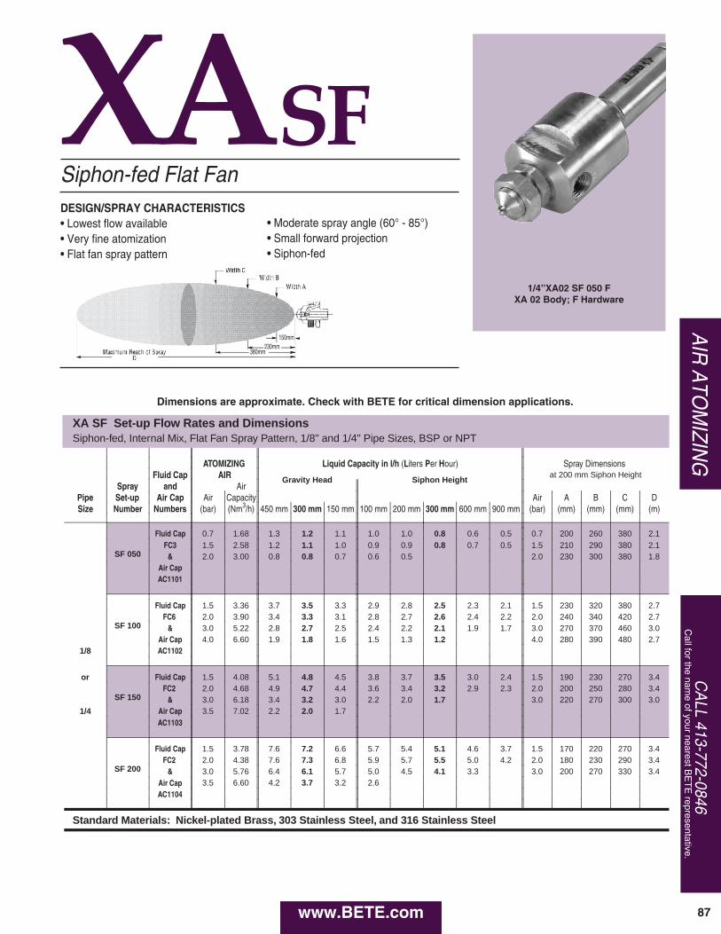
CALL 413-772-0846
Call for the nam
e of your nearest BE
TE
representative.
87
AIR ATO
MIZIN
G
www.BETE.com
XASF
XA SF Set-up Flow Rates and DimensionsSiphon-fed, Internal Mix, Flat Fan Spray Pattern, 1/8" and 1/4" Pipe Sizes, BSP or NPT
ATOMIZING Liquid Capacity in l/h ( L iters P er H our) Spray Dimensions Fluid Cap AIR Gravity Head Siphon Height
at 200 mm Siphon Height
Spray and Air Pipe Set-up Air Cap Air Capacity Air A B C D Size Number Numbers (bar) (Nm 3 /h) 450 mm 300 mm 150 mm 100 mm 200 mm 300 mm 600 mm 900 mm (bar) (mm) (mm) (mm) (m)
SF 050
Fluid Cap 0.7 1.68 1.3 1.2 1.1 1.0 1.0 0.8 0.6 0.5 0.7 200 260 380 2.1 FC3 1.5 2.58 1.2 1.1 1.0 0.9 0.9 0.8 0.7 0.5 1.5 210 290 380 2.1
& 2.0 3.00 0.8 0.8 0.7 0.6 0.5 2.0 230 300 380 1.8 Air Cap AC1101
SF 100
Fluid Cap 1.5 3.36 3.7 3.5 3.3 2.9 2.8 2.5 2.3 2.1 1.5 230 320 380 2.7 FC6 2.0 3.90 3.4 3.3 3.1 2.8 2.7 2.6 2.4 2.2 2.0 240 340 420 2.7
& 3.0 5.22 2.8 2.7 2.5 2.4 2.2 2.1 1.9 1.7 3.0 270 370 460 3.0 Air Cap 4.0 6.60 1.9 1.8 1.6 1.5 1.3 1.2 4.0 280 390 480 2.7
1/8 AC1102
or
SF 150
Fluid Cap 1.5 4.08 5.1 4.8 4.5 3.8 3.7 3.5 3.0 2.4 1.5 190 230 270 3.4 FC2 2.0 4.68 4.9 4.7 4.4 3.6 3.4 3.2 2.9 2.3 2.0 200 250 280 3.4
& 3.0 6.18 3.4 3.2 3.0 2.2 2.0 1.7 3.0 220 270 300 3.0 1/4 Air Cap 3.5 7.02 2.2 2.0 1.7
AC1103
SF 200
Fluid Cap 1.5 3.78 7.6 7.2 6.6 5.7 5.4 5.1 4.6 3.7 1.5 170 220 270 3.4 FC2 2.0 4.38 7.6 7.3 6.8 5.9 5.7 5.5 5.0 4.2 2.0 180 230 290 3.4
& 3.0 5.76 6.4 6.1 5.7 5.0 4.5 4.1 3.3 3.0 200 270 330 3.4 Air Cap 3.5 6.60 4.2 3.7 3.2 2.6 AC1104
Standard Materials: Nickel-plated Brass, 303 Stainless Steel, and 316 Stainless Steel
X Set-up Flow RatesP NPT
F
Siphon-fed Flat FanDESIGN/SPRAY CHARACTERISTICS• Lowest flow available• Very fine atomization• Flat fan spray pattern
• Moderate spray angle (60° - 85°)• Small forward projection• Siphon-fed
1/4”XA02 SF 050 FXA 02 Body; F Hardware
150mm230mm
380mm
Dimensions are approximate. Check with BETE for critical dimension applications.

www.BETE.com88
AIR ATO
MIZING
TO O
RD
ER:specify pipe size, body style, spray set-up #,
hardware and mounting assemblies, and material. See page 78.
XAEF
XA EF Set-up Flow Rates and DimensionsPressure-fed, External Mix, Flat Fan Spray Pattern, 1/8" and 1/4" Pipe Sizes, BSP or NPT
Fluid 0.2 Bar Liquid 0.3 Bar Liquid 0.7 Bar Liquid 1.5 Bar Liquid 3.0 Bar Liquid Spray Dimensions Spray and
Nm 3
h Nm 3
h Nm 3
h Nm 3
h Nm 3
h Pipe Set-up Air Cap Air
l/h Air
l/h Air
l/h Air
l/h Air
l/h Bar A B C D
Size Number Numbers (bar) (bar) (bar) (bar) (bar) air liquid (mm) (mm) (mm) (m)
0.4 0.3 200 280 330 1.2 Fluid Cap 0.4 1.32 0.4 1.32 0.4 1.50 0.6 1.68 0.7 2.04 0.6 0.7 230 300 400 1.8
EF 050
FC7 & 0.4 1.50 0.4 1.50 0.6 1.68 0.7 2.04 1.1 2.70 0.6 1.5 280 350 460 1.8 & 3 4 5 8 11 1.1 1.5 280 330 430 2.4
Air Cap 0.5 1.62 0.6 1.68 0.7 2.04 1.1 2.70 1.8 3.72 1.4 1.5 250 300 410 2.7 AC1001 0.6 1.68 0.7 2.04 0.9 2.40 1.4 3.24 2.5 4.74 1.1 2.0 280 350 480 2.6
1.4 3.0 300 380 510 2.7
0.2 1.51 0.4 1.58 0.7 1.87 1.4 2.72 2.8 4.38 0.2 0.2 90 150 230 0.9
EF 100
Fluid Cap 0.4 1.58 0.7 1.87 1.1 2.38 1.8 3.23 3.5 5.10 1.1 0.2 90 150 230 1.2 FC7 0.7 1.87 1.1 2.38 1.4 2.72 2.1 3.57 4.2 6.12 1.4 0.4 100 150 230 1.2
& 1.1 3 2.38 1.4 4 2.72 1.8 5 3.23 2.8 8 4.42 4.9 11 7.14 1.4 1.4 120 180 250 1.5 Air Cap 1.4 2.72 1.8 3.23 2.1 3.56 3.5 5.10 5.3 7.65 1.8 0.7 120 150 240 1.5 AC1003 1.8 3.23 2.1 3.56 2.8 4.42 4.2 6.12 5.6 8.34 2.8 1.4 130 180 280 1.8
2.1 3.56 2.8 4.42 3.5 5.10 5.6 8.34 6.3 9.54 4.9 2.8 150 180 240 2.4
0.7 0.3 280 330 400 1.5
EF 150
Fluid Cap 0.4 1.32 0.4 1.32 0.6 1.68 0.7 2.04 1.1 2.70 1.1 0.7 300 380 480 2.1 FC4 0.6 1.68 0.7 2.04 0.7 2.04 1.4 3.24 1.4 3.24 0.7 1.5 380 460 580 1.8
& 5 6 8 12 17 1.4 1.5 350 430 560 2.4 Air Cap 0.7 2.04 1.1 2.70 1.4 3.24 2.1 4.26 2.1 4.26 2.5 1.5 330 400 510 3.0
1/8 AC1001 1.1 2.70 1.4 3.24 2.1 4.26 2.5 4.74 2.5 4.74 1.8 2.0 380 460 580 2.7 1.8 3.0 410 480 660 2.9
or 0.4 1.58 0.7 1.87 1.1 2.38 1.8 3.23 3.2 4.92 0.4 0.2 80 140 220 1.0
EF 200
Fluid Cap 0.7 1.87 1.1 2.38 1.4 2.72 2.1 3.56 3.5 5.10 1.4 0.2 90 150 220 1.7 FC4 1.1 2.38 1.4 2.72 1.8 3.23 2.8 4.42 4.2 6.12 1.8 0.4 100 170 230 1.8
1/4 & 1.4 5 2.72 1.8 6 3.23 2.1 8 3.56 3.5 12 5.10 4.9 17 7.14 1.8 1.4 130 190 290 2.1 Air Cap 1.8 3.23 2.1 3.56 2.8 4.42 4.2 6.12 5.3 7.62 2.1 0.7 130 180 250 1.8 AC1003 2.1 3.56 2.8 4.42 3.5 5.10 4.9 7.14 6.3 9.54 3.5 1.4 130 220 300 2.4
2.8 4.42 3.5 5.10 4.2 6.12 6.3 9.54 6.7 9.84 5.3 2.8 150 190 250 3.0
0.6 0.3 350 480 610 1.8
EF 250
Fluid Cap 0.4 1.50 0.4 1.50 0.4 1.50 0.7 2.04 1.4 3.24 0.6 0.7 350 480 630 1.5 FC3 0.5 1.65 0.6 1.68 0.6 1.68 0.9 2.40 1.8 3.72 0.7 1.5 380 480 630 1.8
& 9 10 16 23 33 1.1 1.5 410 510 660 2.1 Air Cap 0.6 1.68 0.7 1.86 0.7 2.04 1.1 2.70 2.1 4.26 1.4 1.5 430 530 660 2.4 AC1001 0.7 2.04 0.7 2.04 0.9 2.40 1.4 3.24 2.5 4.74 1.8 2.0 410 510 690 2.7
2.1 3.0 410 510 690 2.9
0.7 1.87 1.1 2.38 1.4 2.72 2.5 4.08 3.5 5.10 0.7 0.2 130 170 250 1.2
EF 300
Fluid Cap 1.1 2.38 1.4 2.72 1.8 3.23 2.8 4.42 4.2 6.12 1.8 0.2 130 170 250 1.8 FC3 1.4 2.72 1.8 3.23 2.1 3.56 3.5 5.10 4.9 7.14 2.1 0.4 130 180 240 1.8
& 1.8 9 3.23 2.1 10 3.56 2.8 16 4.42 4.2 23 6.12 5.3 33 7.62 2.5 1.4 140 200 320 1.8 Air Cap 2.1 3.56 2.8 4.42 3.5 5.10 4.9 7.14 5.6 8.34 2.8 0.7 140 190 300 2.3 AC1003 2.8 4.42 3.5 5.10 4.2 6.12 5.6 8.34 6.3 9.54 4.2 1.4 140 200 360 3.0
3.5 5.10 4.2 6.12 4.9 7.14 6.3 9.54 7.0 10.56 5.3 2.8 170 200 300 4.0
Standard Materials: Nickel-plated Brass, 303 Stainless Steel, and 316 Stainless Steel
3
Pressure-fed/External Mix/Flat Fan
• Moderate spray angle (60°- 90°)• Precise metering of the liquid flow rate
DESIGN FEATURES• External mix: allows spraying of
viscous materials• Variable atomization
1/4”XA EF 150 EXA 00 Body; E Hardware
150mm230mm
380mm
Dimensions are approximate. Check with BETE for critical dimension applications.

CALL 413-772-0846
Call for the nam
e of your nearest BE
TE
representative.
89
AIR ATO
MIZIN
G
www.BETE.com
XA EF Set-up Flow Rates and DimensionsPressure-fed, External Mix, Flat Fan Spray Pattern, 1/8" and 1/4" Pipe Sizes, BSP or NPT
Fluid 0.2 Bar Liquid 0.3 Bar Liquid 0.7 Bar Liquid 1.5 Bar Liquid 3.0 Bar Liquid Spray Dimensions Spray and
Nm 3
h Nm 3
h Nm 3
h Nm 3
h Nm 3
h Pipe Set-up Air Cap Air
l/h Air
l/h Air
l/h Air
l/h Air
l/h Bar A B C D
Size Number Numbers (bar) (bar) (bar) (bar) (bar) air liquid (mm) (mm) (mm) (m)
1.4 0.3 330 380 480 3.8 Fluid Cap 0.6 5.46 0.7 6.12 1.4 9.36 2.1 12.6 3.2 17.1 2.1 0.7 330 400 560 4.3
EF 350 FC6 0.7 6.12 1.1 7.80 2.1 12.6 2.8 15.6 4.2 21.6 2.1 1.5 350 460 580 4.0 & 13 16 25 37 52 3.2 1.5 380 480 660 4.6
Air Cap 1.1 7.80 1.8 11.0 2.5 14.1 3.5 18.6 5.3 25.8 4.2 1.5 380 480 640 5.2 AC1002 1.4 9.36 2.1 12.6 2.8 15.6 4.2 21.6 5.6 27.3 3.9 2.0 410 510 690 4.6
0.7 5.10 1.0 6.12 1.4 6.96 2.5 10.7 3.2 12.7 0.7 0.2 130 190 250 1.7
EF 400
Fluid Cap 1.0 6.12 1.4 6.96 1.8 8.34 2.8 11.7 3.5 13.9 1.8 0.2 130 190 250 2.7 FC6 1.4 6.96 1.8 8.34 2.1 9.36 3.5 13.6 3.9 15.3 2.1 0.4 150 190 280 3.0 & 1.8 13 8.34 2.1 16 9.36 2.5 25 10.7 4.2 37 16.0 4.2 52 16.5 2.5 0.7 150 220 280 3.5
Air Cap 2.1 9.36 2.8 11.7 2.8 11.7 4.9 18.7 4.9 18.8 2.5 1.4 170 230 360 3.7 AC1004 2.8 11.7 3.5 13.6 3.5 13.6 5.6 21.6 5.6 21.6 4.2 1.4 170 230 370 4.3
3.5 13.6 4.2 16.0 4.2 16.0 6.3 24.7 6.3 24.7 4.9 2.8 170 220 320 4.9
1.1 0.2 330 380 510 3.5
EF 450
Fluid Cap 0.6 5.46 0.7 6.12 1.1 7.80 2.5 14.1 3.5 18.6 1.8 0.7 350 480 640 3.0 FC2 1.1 7.80 1.4 9.36 1.8 11.0 3.2 17.1 4.6 22.8 2.5 1.5 380 460 640 3.8 & 18 22 33 48 68 3.2 1.5 330 430 610 4.3
Air Cap 1.4 9.36 1.8 11.0 2.5 14.1 3.9 19.8 6.0 28.5 4.2 1.5 300 430 580 4.9 AC1002 1.8 11.0 2.1 12.6 2.8 15.6 4.2 21.6 6.7 31.5 4.2 2.0 330 430 610 5.2
4.9 3.0 330 430 600 4.0
0.7 5.10 1.4 6.96 1.8 8.34 2.8 11.7 3.5 13.9 0.7 0.4 150 190 270 2.1
EF 500
Fluid Cap 1.0 6.12 1.8 8.34 2.1 9.36 3.2 12.7 4.2 16.5 1.8 0.7 150 190 270 3.0 FC2 1.4 6.96 2.1 9.36 2.5 10.7 3.5 13.6 4.9 18.8 2.5 1.4 150 220 330 3.4 & 1.8 18 8.34 2.5 22 10.7 2.8 33 11.7 4.2 48 16.0 5.3 68 20.4 2.8 1.4 150 220 360 3.8
Air Cap 2.1 9.36 2.8 11.7 3.5 13.6 4.9 18.7 5.6 21.6 2.8 1.4 170 250 370 4.0 AC1004 2.8 11.7 3.5 13.6 4.2 16.0 5.6 21.6 6.3 24.7 4.2 2.1 170 250 370 4.9
3.5 13.6 4.2 16.0 4.9 18.7 6.3 24.7 6.6 25.7 5.3 2.8 180 230 360 5.8
2.1 0.3 400 560 760 3.0
EF 550
Fluid Cap 0.7 6.12 1.1 7.80 1.8 11.0 3.2 17.1 5.3 25.8 2.8 0.7 460 580 810 4.0 FC1 1.1 7.80 1.4 9.36 2.1 12.6 3.5 18.6 6.0 28.5 3.2 1.5 480 580 790 4.3 & 36 45 68 100 141 4.6 1.5 430 530 760 4.9
1/8 Air Cap 1.4 9.36 2.1 12.6 2.8 15.6 4.9 24.3 6.7 31.5 5.6 1.5 380 510 660 5.8 AC1002 1.8 11.0 2.5 14.1 3.2 17.1 5.9 27.3 7.0 33.0 3.9 2.0 480 640 840 4.3
6.3 3.0 410 560 790 5.8 OR
1.0 6.12 1.8 8.34 2.5 10.7 3.2 12.7 3.9 15.3 1.0 0.2 150 200 250 2.7
EF 600
Fluid Cap 1.4 6.96 2.1 9.36 2.8 11.7 3.5 13.6 4.2 16.5 2.1 0.2 150 220 290 3.0 1/4 FC1 1.8 8.34 2.5 10.7 3.2 12.7 3.9 14.8 4.6 17.8 2.8 0.4 180 240 360 3.5
& 2.1 36 9.36 2.8 45 11.7 3.5 68 13.6 4.2 100 16.0 4.9 141 18.8 3.2 1.4 200 280 390 3.7 Air Cap 2.5 10.7 3.2 12.7 4.2 16.0 4.9 18.7 5.6 21.6 3.5 0.7 190 270 380 4.0 AC1004 2.8 11.7 3.5 13.6 4.9 18.7 5.6 21.6 6.3 24.7 4.2 1.4 200 280 390 4.3
3.5 13.6 4.2 16.0 5.6 21.6 6.3 24.7 7.0 27.2 5.6 2.8 180 240 380 5.9
1.8 14.1 1.8 14.1 2.5 18.0 3.9 24.6 1.8 0.2 150 200 290 3.0
EF 650
Fluid Cap 2.1 15.6 2.1 15.6 2.8 19.8 4.2 26.7 2.8 0.2 150 200 300 3.4 FC8 2.5 18.0 2.5 18.0 3.2 21.3 4.6 28.8 2.8 0.3 150 200 300 4.0 & 2.8 36 19.8 2.8 45 19.8 3.5 68 22.8 4.9 100 31.2 3.5 0.7 170 220 320 4.3
Air Cap 3.2 21.3 3.2 21.3 3.9 24.6 5.3 33.9 3.9 1.5 170 220 340 4.6 AC1005 3.5 22.8 3.5 22.8 4.2 26.7 5.6 36.0 4.2 1.0 170 230 330 4.7
4.2 26.7 4.2 26.7 4.9 31.2 6.3 41.1 4.9 1.5 170 230 340 5.5
2.1 15.6 2.8 19.8 3.9 24.6 4.9 31.2 2.1 0.2 170 240 340 3.5
EF 700
Fluid Cap 2.5 18.0 3.2 21.3 4.2 26.7 5.3 33.9 3.2 0.2 180 240 360 4.3 FC9 2.8 19.8 3.5 22.8 4.6 28.8 5.6 36.0 3.9 0.3 180 250 360 4.9 & 3.2 64 21.3 3.9 78 24.6 4.9 119 31.2 6.0 175 38.4 4.9 0.7 180 250 360 5.5
Air Cap 3.5 22.8 4.2 26.7 5.3 33.9 6.3 41.1 4.9 1.5 200 250 380 5.5 AC1005 4.2 26.7 4.9 31.2 5.6 36.0 5.3 1.0 180 250 380 5.8
4.9 31.2 5.6 36.0 6.3 41.1 5.6 1.5 200 250 380 6.1
2.8 19.8 3.5 22.8 4.6 28.8 5.6 36.0 2.8 0.2 190 250 360 4.6
EF 750
Fluid Cap 3.2 21.3 3.9 24.6 4.9 31.2 6.0 38.4 3.9 0.2 200 250 370 4.9 FC5 3.5 22.8 4.2 26.7 5.3 33.9 6.3 41.1 4.6 0.3 200 250 370 5.2 & 3.9 102 24.6 4.6 125 28.8 5.6 192 36.0 280 5.3 0.7 220 270 380 5.5
Air Cap 4.2 26.7 4.9 31.2 6.0 38.4 5.6 1.0 220 270 410 5.5 AC1005 4.6 28.8 5.3 33.9 6.3 41.1 5.6 1.5 220 270 410 5.8
4.9 31.2 5.6 36.0 6.0 1.5 220 270 410 6.1
Standard Materials: Nickel-plated Brass, 303 Stainless Steel, and 316 Stainless Steel
150mm230mm
380mm
Dimensions are approximate. Check with BETE for critical dimension applications.

www.BETE.com90
AIR ATO
MIZING
TO O
RD
ER:specify pipe size, body style, spray set-up #,
hardware and mounting assemblies, and material. See page 78.
XAERPressure-fed/Ext. Mix/Narrow Angle Round
Dimensions are approximate. Check with BETE for critical dimension applications.
XA ER Set-up Flow Rates and Spray DimensionsPressure-fed, External Mix, Narrow Round Spray Pattern, 1/8" and 1/4" Pipe Sizes
PipeSize
Spray Fluid and 0.2 BAR Liquid 0.3 BAR Liquid 0.7 BAR Liquid 1.5 BAR Liquid 3 BAR Liquid Spray DimensionsSet-up Air Cap BAR BAR BAR BAR BAR BAR A B C D
Number Numbers air L/h Nm3/h air L/h Nm3/h air L/h Nm3/h air L/h Nm3/h air L/h Nm3/h Liquid Air mm mm mm m0.3 1.3 0.7 1.9 1.4 2.9 0.2 0.7 50 90 130 2.3
Fluid Cap 0.3 1.3 0.3 1.3 0.7 1.9 1.4 2.9 2.1 3.7 0.3 1.4 60 90 110 3ER 050 FC7 0.7 2.7 1.9 0.7 3 1.9 1.4 4.4 2.9 2.1 6.6 3.7 2.8 9.5 4.6 0.3 2.8 40 90 130 3.7
& 1.4 2.9 1.4 2.9 2.1 3.7 2.8 4.6 3.4 5.6 0.7 2.8 60 80 130 4.9Air Cap 2.1 3.7 2.1 3.7 2.8 4.6 3.4 5.6 4.1 6.5 1.5 1.4 60 60 80 4.3AC1801 2.8 4.6 3.4 5.6 4.1 6.5 4.8 7.6 1.5 2.8 60 60 90 5.5
5.5 8.5 6.2 9.4 3.0 4.1 70 70 100 6.10.3 1.3 0.7 1.9 1.4 2.9 1.4 2.9 0.2 0.7 50 60 80 3
Fluid Cap 0.3 1.3 0.7 1.9 1.4 2.9 2.1 3.7 2.1 3.7 0.3 1.4 60 80 80 4.3ER 150 FC4 0.7 3.7 1.9 1.4 4.5 2.9 2.1 7.4 3.7 2.8 11 4.6 2.8 15 4.6 0.3 2.8 60 60 110 4.9
& 1.4 2.9 2.1 3.7 2.8 4.6 3.4 5.6 3.4 5.6 0.7 2.8 60 80 100 5.5Air Cap 2.1 3.7 2.8 4.6 3.4 5.6 4.1 6.5 4.1 6.5 1.5 1.4 80 80 130 4AC1801 2.8 4.6 3.4 5.6 4.1 6.5 4.8 7.6 4.8 7.6 1.5 2.8 70 90 100 5.5
6.2 9.4 6.2 9.4 3.0 4.1 80 100 140 6.10.4 1.4 0.7 1.9 0.7 1.9 1.4 2.9 2.8 4.6 0.2 0.7 80 90 100 3
Fluid Cap 0.7 1.9 1.4 2.9 1.4 2.9 2.1 3.7 3.4 5.6 0.3 1.4 80 80 130 4.3ER 250 FC3 1.4 7.7 2.9 2.1 9.5 3.7 2.1 15 3.7 2.8 18 4.6 4.1 23 6.5 0.3 2.8 70 80 120 4.3
& 2.1 3.7 2.8 4.6 2.8 4.6 3.4 5.6 4.8 7.6 0.7 2.8 80 90 130 5.2Air Cap 2.8 4.6 3.4 5.6 3.4 5.6 4.1 6.5 5.5 8.5 1.5 1.4 80 110 110 5.5AC1801 3.4 5.6 4.1 6.5 4.1 6.5 4.8 7.6 6.2 9.4 1.5 2.8 80 100 130 4.9
6.2 9.4 3.0 4.1 90 100 130 5.20.7 5.5 0.7 5.5 2.1 11.6 2.8 14.3 0.2 0.7 80 130 150 2.7
Fluid Cap 1.0 7.2 1.4 8.8 1.4 8.8 2.8 14.3 3.4 17 0.3 1.4 80 100 150 3.4ER 350 FC6 1.4 12 8.8 2.1 15 11.6 2.1 22 11.6 3.4 32 17 4.1 47 19.6 0.3 2.8 80 100 150 4.9
& 2.1 11.6 2.8 14.3 2.8 14.3 4.1 19.6 4.8 22.3 0.7 2.8 80 100 150 4.9Air Cap 2.8 14.3 3.4 17.0 3.4 17 4.8 22.3 5.5 25.1 1.5 2.1 80 100 150 4.6AC1802 3.4 17 4.1 19.6 4.1 19.6 5.5 25.1 6.2 26.9 1.5 4.1 80 130 180 5.2
6.2 26.9 3.0 4.1 80 130 150 5.50.7 5.5 0.7 5.5 1 7.2 2.1 11.6 0.2 0.7 100 140 210 4.3
Fluid Cap 1 7.2 1 7.2 1.4 8.8 2.8 14.3 2.8 14.3 0.3 1.4 110 130 150 5.5ER 450 FC2 1.4 19 8.8 1.4 23 8.8 2.1 33 11.6 3.4 49 17 3.4 72 17 0.3 2.8 100 110 140 6.4
& 2.1 11.6 2.1 11.6 2.8 14.3 4.1 19.6 4.1 19.6 0.7 2.8 130 120 180 6.7Air Cap 2.8 14.3 2.8 14.3 3.4 17 4.8 22.3 4.8 22.3 1.5 2.1 120 110 160 6.1AC1802 3.4 17 3.4 17 4.1 19.6 5.5 25.1 5.5 25.1 1.5 4.1 100 130 180 6.7
4.1 19.6 4.8 22.2 3.0 4.1 110 100 180 6.72.1 11.6 0.2 1.4 140 150 220 4.9
Fluid Cap 1 7.2 1.4 8.8 2.8 14.3 2.8 14.3 3.4 17 0.3 1.4 130 150 230 4.6ER 550 FC1 1.4 39 8.8 2.1 46 11.6 3.4 68 17 3.4 97 17 4.1 119 19.6 0.3 2.8 130 170 180 6.4
& 2.1 11.6 2.8 14.3 4.1 19.6 4.1 19.6 4.8 22.3 0.7 4.1 140 150 240 6.7Air Cap 2.8 14.3 3.4 17 4.8 22.3 4.8 22.3 5.5 25.1 1.5 2.8 110 150 180 6.7AC1802 3.4 17 4.1 19.6 5.5 25.1 5.5 25.1 1.5 4.1 110 130 180 6.7
3.0 5.5 100 130 140 6.71.0 11.6 1.4 14.1 2.1 18.8 3.4 27.7 0.2 1.4 130 150 200 5.2
Fluid Cap 1.4 14.1 1.7 16.6 2.8 23.2 3.8 29.8 0.3 2.1 150 140 150 6.7ER650 FC8 1.7 39 16.6 2.1 46 18.8 3.4 68 27.7 4.1 97 31.9 0.3 3.4 120 130 160 6.7
& 2.1 18.8 2.8 23.2 3.8 29.8 4.5 34 0.7 4.1 130 140 170 6.7Air Cap 2.8 23.2 3.4 27.7 4.1 31.9 4.8 36.1 1.5 3.4 130 150 150 6.7AC1803 3.4 27.7 3.8 29.8 4.5 34.0 5.5 40.5 1.5 4.8 100 130 180 5.5
4.1 31.9 4.1 31.9 4.8 36.1 6.2 44.8 1.5 6.2 100 130 180 5.51.4 14.1 2.1 18.8 2.8 23.2 3.4 27.7 0.2 1.4 150 150 220 5.8
Fluid Cap 2.1 18.8 2.8 23.2 3.4 27.7 3.8 29.8 0.3 2.1 140 160 200 6.4ER750 FC9 2.8 65 23.2 3.4 76 27.7 4.1 110 31.9 4.1 165 31.9 0.3 4.1 150 170 180 6.7
& 3.4 27.7 4.1 31.9 4.5 34 4.5 34 0.7 4.1 130 130 180 6.7Air Cap 3.8 29.8 4.5 34 4.8 36.1 4.8 36.1 1.5 3.4 130 150 200 6.1AC1803 4.1 31.9 4.8 36.1 5.5 40.5 5.5 40.5 1.5 4.8 100 130 200 5.8
4.8 36.1 5.5 40.5 6.2 44.8 6.2 44.8 1.5 6.2 100 150 200 5.80.2 2.8 150 160 180 6.7
Fluid Cap 2.8 23.2 3.8 29.8 4.5 34 0.3 4.8 90 110 180 6.1ER850 FC5 3.4 95 27.7 4.1 109 31.9 4.8 158 36.1 5.5 234 40.5 0.7 4.8 90 110 150 5.8
& 3.8 29.8 4.5 34 5.5 40.5 6.2 44.8 0.7 6.2 80 100 150 5.5Air Cap 4.1 31.9 4.8 36.1 6.2 44.8 1.5 5.5 90 100 150 5.5AC1803 4.5 34 5.5 40.5 1.5 6.2 80 100 140 5.8
1/8”
or
1/4”
DESIGN/SPRAY CHARACTERISTICS• External mix: allows spraying of
viscous liquids• Variable atomization
• Narrow spray angle (10°- 30°)• Precise metering of liquid flow rate
Standard Materials: Nickel Plated Brass, 303 Stainless Steel, and 316 Stainless Steel.
1/4” XAER850AXA 00 Body; A Hardware
1.25m0.75m
0.5m

CALL 413-772-0846
Call for the nam
e of your nearest BE
TE
representative.
91
AIR ATO
MIZIN
G
www.BETE.com
XAFFPressure-fed/Int. Mix/Deflected Flat Fan
XAXWPressure-fed/Int. Mix/Extra-wide AngleDESIGN/SPRAY CHARACTERISTICS• Internal mix• Very fine atomization• 180° Extra-wide Hollow Cone
DESIGN/SPRAY CHARACTERISTICS• Internal mix• Very fine atomization• Deflected flat fan spray pattern
1/4”XA 01 FF050 FXA01 Body; F Hardware
1/4”XA 03 XW050 AXA 03 Body; A Hardware
Set-up Flow Rates and DimensionsS
( L i H o F
2
2
Nickel-plated Brass, 303 Stainless Steel, and 316 Stainless Steel
XA FF Set-up Flow RatesPressure-fed, Internal Mix, Deflected Flat Fan Spray Pattern, 1/8" and 1/4" Pipe Sizes, BSP or NPT
Fluid 0.7 Bar Liquid 1.5 Bar Liquid 2.0 Bar Liquid 3.0 Bar Liquid 4.0 Bar Liquid Spray and
Pipe Set-up Air Cap Air l/hr Nm 3
hr
Air l/hr Nm 3
hr
Air l/hr Nm 3
hr
Air l/hr Nm 3
hr
Air l/hr Nm 3
hr Size Number Numbers (bar) (bar) (bar) (bar) (bar)
1/8
FF 050
0.4 11.0 2.70 1.1 14.5 4.74 1.5 15.7 5.76 2.1 20.0 6.84 2.7 26.0 7.98 Fluid Cap 0.6 9.5 3.24 1.3 13.2 5.16 1.7 14.3 6.24 2.2 19.2 7.26 3.2 22.0 9.60
or FC10 0.7 7.6 3.90 1.4 11.8 5.70 1.8 12.9 6.72 2.7 15.8 8.76 3.8 17.7 11.2 & 0.8 5.7 4.62 1.5 10.0 6.18 2.1 9.8 7.80 3.1 11.8 10.4 4.4 13.1 13.8
1/4 Air Cap 1.7 8.7 6.78 2.2 8.3 8.52 3.2 10.3 11.0 4.6 10.2 15.0 AC1701
Set-up Flow Rates and DimensionsS
( L i H o a
B
Nickel-plated Brass, 303 Stainless Steel, and 316 Stainless Steel
XA XW Set-up Flow Rates Pressure-fed, Internal Mix, Extra-wide Spray Pattern, 1/8" and 1/4" Pipe Sizes, BSP or NPT
Fluid 0.7 Bar Liquid 1.5 Bar Liquid 2.0 Bar Liquid 3.0 Bar Liquid 4.0 Bar Liquid Spray and
Pipe Set-up Air Cap Air l/h Nm 3
h
Air l/h Nm 3
h
Air l/h Nm 3
h
Air l/h Nm 3
h
Air l/h Nm 3
h Size Number Numbers (bar) (bar) (bar) (bar) (bar) 1
Fluid Cap 1.4 15.1 4.14 2.8 19.5 8.52 3.5 21.0 11.1 4.2 48.0 12.6 6.0 45.0 20.4 1/8 FC8 1.5 10.6 4.62 3.0 16.1 9.18 3.7 17.6 11.8 4.6 37.0 14.4 6.3 37.0 22.5 or XW 050 & 1.7 7.6 5.04 3.1 13.2 9.90 3.8 14.8 12.6 4.9 28.0 16.5 6.7 30.0 24.3 1/4 Air Cap 1.8 5.7 5.58 3.2 10.6 10.6 3.9 12.5 13.2 5.6 15.5 20.4 7.0 24.0 26.4
AC1401 2.0 4.2 6.18 3.4 8.3 11.3 4.2 8.1 14.7 6.3 7.8 25.5
Standard Materials: Nickel-plated Brass, 303 Stainless Steel, and 316 Stainless Steel
3

www.BETE.com92
AIR ATO
MIZING
TO O
RD
ER:specify pipe size, body style, spray set-up #,
hardware and mounting assemblies, and material. See page 78.
AD 1/2" XA AD Set-up Flow Rates and Dimensions Pressure-fed, Internal Mix, Wide Angle Round Spray Pattern, 1/2" Pipe Size, BSP or NPT
Spray Fluid and 0.35 Bar Liquid 1.0 Bar Liquid 2.0 Bar Liquid 3.0 Bar Liquid 4.0 Bar Liquid Spray Dimensions
Pipe Set-up Air Cap Air l/h
Nm 3
h Air
l/h Nm 3
h Air
l/h Nm 3
h Air
l/h Nm 3
h Air
l/h Nm 3
h
bar A B C D Size Number Numbers (bar) (bar) (bar) (bar) (bar) air liquid (mm) (mm) (mm) (m)
1/2
AD 5050
Fluid Cap 2.1 213 10.6 3.1 316 12.8 4.2 238 21.1 2.1 2.0 360 480 690 6.7 FC501 2.3 127 14.9 3.2 195 17.5 4.3 154 26.3 3.2 3.0 360 480 690 7.3
& 3.4 107 22.3 4.5 100 31.3 4.3 4.0 360 480 690 8.5 Air Cap AC5601
AD 5100
Fluid Cap 0.6 102 11.0 1.1 215 9.18 2.5 185 21.3 3.7 192 33.6 5.0 230 49.8 0.7 0.35 330 470 650 6.1 FC501 0.7 57 13.8 1.3 124 13.8 2.7 146 24.6 3.9 150 37.2 5.3 158 56.4 1.3 1.0 340 480 670 7.9
& 0.85 32 16.8 1.4 84 16.8 2.8 112 27.9 4.0 119 40.8 5.6 108 64.8 2.8 2.0 330 470 650 6.4 Air Cap 3.0 86 31.2 4.2 86 46.2 4.0 3.0 340 480 670 7.3 AC5602 3.1 65 34.8 4.6 51 5.3 4.0 360 480 690 8.2
AD 5150
Fluid Cap 0.7 129 19.5 1.7 182 32.4 3.1 265 48.6 4.3 350 60.0 0.85 0.35 360 500 690 7.9 FC501 0.85 82 22.2 1.8 143 35.4 3.2 215 51.6 4.6 260 64.8 1.7 1.0 330 480 660 7.3
& 1.0 45 24.9 3.4 173 54.6 5.0 186 72.0 3.4 2.0 330 470 660 7.0 Air Cap 3.5 136 57.0 4.6 3.0 360 500 690 8.5 AC5603 3.6 120 58.8
AD 5200
0.7 134 18.9 1.3 320 26.4 2.1 575 34.2 3.0 740 42.6 3.9 840 51.6 0.7 0.35 330 640 910 3.4 0.85 100 22.8 1.4 255 31.2 2.2 505 38.4 3.1 690 46.2 4.1 790 55.8 1.4 1.0 330 660 910 4.9
1.5 200 35.4 2.4 440 43.2 3.2 630 50.4 4.2 740 59.4 2.5 2.0 280 560 810 6.1 Fluid Cap 1.7 154 40.2 2.5 380 47.4 3.4 570 54.6 4.4 690 64.2 3.4 3.0 280 530 740 6.7
FC502 2.7 330 51.6 3.5 520 58.8 4.5 650 68.4 4.5 4.0 280 560 790 7.6 & 2.8 275 55.8 3.7 470 63.0 4.6 600 72.6
Air Cap 3.0 235 60.6 3.8 420 67.2 4.8 550 76.8 AC5604 3.1 195 64.8 3.9 345 71.4 4.9 510 81.0
4.1 325 75.6 5.1 465 85.8 5.2 425 89.4 5.3 390 93.6 5.5 350 98.4
PR 1/2" XA PR Set-up Flow Rates and Dimensions Pressure-fed, Internal Mix, Round Spray Pattern, 1/2" Pipe Size, BSP or NPT
Spray Fluid and 0.35 Bar Liquid 1.0 Bar Liquid 2.0 Bar Liquid 3.0 Bar Liquid 4.0 Bar Liquid Spray Dimensions
Pipe Set-up Air Cap Air l/h
Nm 3
h Air
l/h Nm 3
h Air
l/h Nm 3
h Air
l/h Nm 3
h Air
l/h Nm 3
h
bar A B C D Size Number Numbers (bar) (bar) (bar) (bar) (bar) air liquid (mm) (mm) (mm) (m)
1/2
PR 5050
Fluid Cap 1.3 34 21.0 1.7 146 21.9 3.0 230 30.6 1.4 0.35
90 160 250
6.7 FC501 1.4 25 23.4 1.8 121 23.7 3.1 200 33.0 2.0 1.0 7.3
& 1.5 20 24.9 2.0 102 25.8 3.2 176 35.4 3.2 2.0 8.2 Air Cap 1.7 15.5 26.7 2.1 86 27.6 3.4 154 37.2 AC5501 2.3 72 29.4 3.5 135 39.6
2.4 60 31.2 3.6 118 42.0
PR 5100
0.7 134 18.9 1.3 320 26.4 2.1 575 34.2 3.0 740 42.6 3.9 840 51.6 0.7 0.35 100 180 230 7.0 0.85 100 22.8 1.4 255 31.2 2.2 505 38.4 3.1 690 46.2 4.1 790 55.8 1.4 1.0 150 250 330 6.4
1.5 200 35.4 2.4 440 43.2 3.2 630 50.4 4.2 740 59.4 2.5 2.0 130 200 250 11.3 Fluid Cap 1.7 154 40.2 2.5 380 47.4 3.4 570 54.6 4.4 690 64.2 3.4 3.0 100 180 250 12.5
FC502 2.7 330 51.6 3.5 520 58.8 4.5 650 68.4 4.5 4.0 100 180 250 14.3 & 2.8 275 55.8 3.7 470 63.0 4.6 600 72.6
Air Cap 3.0 235 60.6 3.8 420 67.2 4.8 550 76.8 AC5502 3.1 195 64.8 3.9 345 71.4 4.9 510 81.0
4.1 325 75.6 5.1 465 85.8 5.2 425 89.4 5.3 390 93.6 5.5 350 98.4
Standard Materials: Nickel-plated Brass, 303 Stainless Steel, and 316 Stainless Steel
Air Atomizing
230mm
457mm686mm
1/2XADimensions are approximate. Check with BETE for critical dimension applications.

CALL 413-772-0846
Call for the nam
e of your nearest BE
TE
representative.
93
AIR ATO
MIZIN
G
www.BETE.com
EF 1/2" XA EF Set-up Flow Rates and Dimensions Pressure-fed, External Mix, Flat Fan Spray Pattern, 1/2" Pipe Size, BSP or NPT
Spray Fluid and 0.2 Bar Liquid 0.35 Bar Liquid 0.5 Bar Liquid 0.7 Bar Liquid 1.0 Bar Liquid Spray Dimensions
Pipe Set-up Air Cap Air l/h
Nm 3
h Air
l/h Nm 3
h Air
l/h Nm 3
h Air
l/h Nm 3
h Air
l/h Nm 3
h
bar A B C D Size Number Numbers (bar) (bar) (bar) (bar) (bar) air liquid (mm) (mm) (mm) (m)
1/2 EF 5050
Fluid Cap 2.1
522
52.6 2.8
681
64.5 3.2
795
70.4 3.9
953
81.5 5.6
1158
110 2.5 0.2 216 368 520 5.80 FC501 2.5 57.7 3.2 70.4 3.5 76.4 4.2 87.4 6.0 117 3.5 0.4 229 420 550 6.71
& 2.8 64.5 3.5 76.4 3.9 81.5 4.9 98.4 6.3 122 3.9 0.5 241 445 580 7.02 Air Cap 3.2 70.4 3.9 81.5 4.2 87.4 5.3 105 6.6 127 4.9 0.7 241 460 610 7.63 AC5001 4.2 87.4 4.6 93.3 5.6 110 7.0 132 6.3 1.0 254 480 660 8.85
4.9 98.4 6.0 117
PF 1/2" XA PF Set-up Flow Rates and DimensionsPressure-fed, Internal Mix, Flat Fan Spray Pattern, 1/2" Pipe Size, BSP or NPT
Spray Fluid and 0.35 Bar Liquid 1.0 Bar Liquid 2.0 Bar Liquid 3.0 Bar Liquid 4.0 Bar Liquid Spray Dimensions
Pipe Set-up Air Cap Air l/h
Nm 3
h Air
l/h Nm 3
h Air
l/h Nm 3
h Air
l/h Nm 3
h Air
l/h Nm 3
h
bar A B C D Size Number Numbers (bar) (bar) (bar) (bar) (bar) air liquid (mm) (mm) (mm) (m)
1/2
PF 5050
Fluid Cap 1.8 154 35.4 3.4 184 57.0 2.0 1.0 460 740 910 5.8 FC501 2.0 119 38.4 3.5 157 60.6 3.5 2.0 510 790 970 7.0
& 2.1 93 41.4 3.7 133 63.6 Air Cap 3.8 112 66.6 AC5301
PF 5100
0.7 134 18.9 1.3 320 26.4 2.1 575 34.2 3.0 740 40.8 3.9 840 51.6 0.7 0.35 510 860 1190 4.0 0.85 100 22.8 1.4 255 31.2 2.2 505 38.4 3.1 690 43.2 4.1 790 55.8 1.4 1.0 860 1570 2110 4.6
1.5 200 35.4 2.4 440 43.2 3.2 630 46.1 4.2 740 59.4 2.5 2.0 860 1570 2080 5.2 Fluid Cap 1.7 154 40.2 2.5 380 47.4 3.4 570 50.8 4.4 690 64.2 3.4 3.0 910 1680 2160 5.8
FC502 2.7 330 51.6 3.5 520 54.1 4.5 650 68.4 4.5 4.0 910 1700 2260 6.4 & 2.8 275 55.8 3.7 470 59.3 4.6 600 72.6
Air Cap 3.0 235 60.6 3.8 420 63.3 4.8 550 76.8 AC5302 3.1 195 64.8 3.9 345 69.2 4.9 510 81.0
4.1 325 74.1 5.1 465 85.8 5.2 425 89.4 5.3 390 93.6
5.5 350 98.4
SR 1/2" XA SR Set-up Flow Rates and DimensionsSiphon-fed, External Mix, Round Spray Pattern, 1/2" Pipe Size, BSP or NPT
Liquid Capacity in l/h (Liters P er Hour) Spray Dimensions at
Fluid and ATOMIZING AIR
Gravity Head Siphon Height 200 mm Siphon Ht.
Pipe Set-up Air Cap Air Air Capacity Air B D Size Number Numbers (bar) (Nm 3 /h) 450 mm 300 mm 150 mm 100 mm 200 mm 300 mm 600 mm (bar) (mm) (m)
1/2 SR 5050
0.7 21.6 40 1.5
150
6.1 Fluid Cap 1.5 34.2 97 64 2.0 6.7
FC501 2.0 39.6 117 90 3.0 7.3 & 3.0 52.2 260 225 150 123 90 3.5 7.9
Air Cap 3.5 59.4 300 265 235 163 133 104 4.0 8.8 AC5201 4.0 66.0 305 270 240 170 143 115 5.0 9.8
5.0 78.0 315 280 250 183 157 129 53 5.6 10.7 5.6 87.0 320 290 255 188 164 136 62
X W 1/2" XA XW Set-up Flow Rates and DimensionsPressure-fed, Internal Mix, Extra-wide Angle, Hollow Cone Spray Pattern, 1/2" Pipe Size, BSP or NPT
Spray Fluid and 0.7 Bar Liquid 1.4 Bar Liquid 2.1 Bar Liquid 2.8 Bar Liquid 4.2 Bar Liquid
Pipe Set-up Air Cap Air l/h
Nm 3
h Air
l/h Nm 3
h Air
l/h Nm 3
h Air
l/h Nm 3
h Air
l/h Nm 3
h Size Number Numbers (bar) (bar) (bar) (bar) (bar) 3
1/2 XW 5050
1.0 213 20.7 1.7 394 27.2 2.5 439 38.0 3.4 462 47.2 5.0 484 68.3 1.1 145 25.1 1.8 324 31.6 2.7 372 42.1 3.5 416 50.6 5.2 439 71.8
Fluid Cap 1.3 98 34.5 2.0 275 34.4 2.8 322 45.0 3.7 372 53.4 5.3 409 75.2 FC502 1.4 59 32.3 2.1 207 38.5 3.0 277 49.1 3.8 325 57.3 5.5 366 78.6
& 2.3 159 42.1 3.1 272 52.4 3.9 282 61.1 5.6 325 82.0 Air Cap 2.4 116 45.5 3.2 188 55.8 4.1 250 65.0 5.8 297 85.7 AC5401 2.5 93 49.7 3.4 145 59.4 4.2 209 68.1 5.9 257 89.1
2.7 27 54.0 3.5 114 63.0 4.4 168 71.3 6.0 232 93.0 4.5 141 75.5 6.3 182 100 4.6 77 77.7
Standard Materials: Nickel-plated Brass, 303 Stainless Steel, and 316 Stainless Steel
Dimensions are approximate. Check with BETE for critical dimension applications.
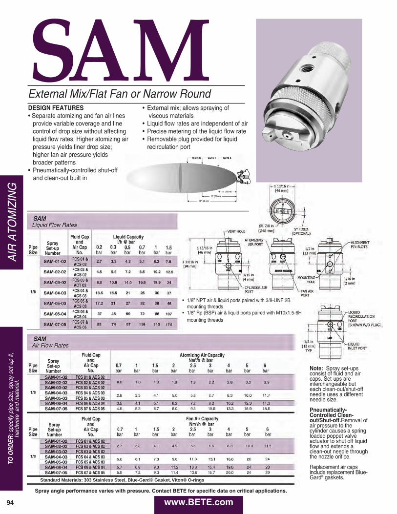
www.BETE.com94
AIR ATO
MIZING
TO O
RD
ER:specify pipe size, spray set-up #,
hardware and material.
SAMExternal Mix/Flat Fan or Narrow Round
P
SpraySet-up
Number
SpraySet-up
Number
SpraySet-up
Number
Standard Materials: 303 Stainless Steel, Blue-Gard® Gasket, Viton® O-rings
Spray angle performance varies with pressure. Contact BETE for specific data on critical applications.
Note: Spray set-upsconsist of fluid and aircaps. Set-ups areinterchangeable but each clean-out/shut-offneedle uses a differentneedle size.
Pneumatically-Controlled Clean-out/Shut-off.Removal ofair pressure to thecylinder causes a springloaded poppet valveactuator to shut off liquidflow and extends aclean-out needle throughthe nozzle orifice.
Replacement air capsinclude replacement Blue-Gard® gaskets.
• 1/8” NPT air & liquid ports paired with 3/8-UNF 2Bmounting threads
• 1/8” Rp (BSP) air & liquid ports paired with M10x1.5-6Hmounting threads
DESIGN FEATURES• Separate atomizing and fan air lines
provide variable coverage and finecontrol of drop size without affectingliquid flow rates. Higher atomizing airpressure yields finer drop size; higher fan air pressure yields broader patterns
• Pneumatically-controlled shut-off and clean-out built in
• External mix; allows spraying ofviscous materials
• Liquid flow rates are independent of air• Precise metering of the liquid flow rate• Removable plug provided for liquid
recirculation port

CALL 413-772-0846
Call for the nam
e of your nearest BE
TE
representative.
95
AIR ATO
MIZIN
G
www.BETE.com
SAM Coverage Chart V a r i ab l e S p r a y , P r e ss u r e F e d , F l a t F an o r *Narrow Round Spray Pattern
0.7 0.2 50 80 100 180 230 250 150 200 280 150 200 280 0.7 60 90 110 180 250 300 180 200 280 180 200 300 1.5 50 80 100 200 300 360 230 280 360 200 250 330
2 0.2 50 80 110 130 150 180 200 250 360 200 280 360 0.7 50 60 . 130 150 180 250 200 250 330 200 250 300 1.5 50 80 100 180 230 330 250 300 380 240 290 370
2.5 0.2 60 90 150 130 150 200 200 250 360 230 280 360 0.7 50 80 130 150 180 250 230 280 360 230 280 330 1.5 50 80 110 180 200 300 250 300 360 250 300 380
4 0.2 60 90 150 100 130 150 200 280 330 230 280 360 0.7 50 80 130 110 130 180 200 250 360 230 300 380 1.5 50 80 110 130 180 230 230 300 410 250 330 430
0.7 0.2 50 80 100 200 250 300 160 220 280 150 230 300 0.7 60 90 110 200 300 380 230 360 460 180 250 330 1.5 50 80 100 200 300 380 200 250 330
2 0.2 50 80 110 140 180 200 200 250 360 200 280 360
1 / 8
0.7 50 80 130 180 230 300 250 300 360 230 250 330 1.5 50 80 100 180 250 300 330 410 460 240 290 370
2.5 0.2 60 90 150 130 180 230 200 250 360 230 280 360 0.7 50 80 130 180 200 160 240 300 360 230 300 380 1.5 50 80 110 160 230 320 290 380 430 280 360 460
4 0.2 60 90 150 110 140 180 200 270 330 230 280 360 0.7 60 100 140 130 150 220 230 280 360 250 300 380 1.5 50 80 110 140 190 240 250 360 460 280 360 460
0.7 0.2 50 80 130 230 300 380 180 230 280 180 230 300 0.7 50 60 100 300 380 530 300 510 580 1.5 250 300 410
2 0.2 60 80 110 150 200 230 200 250 330 200 250 330 0.7 50 80 130 200 280 380 280 330 330 250 280 330 1.5 50 60 100 200 300 360 410 510 560
2.5 0.2 60 90 130 130 180 250 200 250 330 200 280 330 0.7 50 80 130 180 200 280 280 330 380 250 300 330 1.5 50 80 130 180 230 370 330 460 530 300 430 530
4 0.2 60 90 140 130 150 200 200 250 330 200 250 330 0.7 60 90 140 150 180 240 250 330 410 280 330 380 1.5 50 80 110 150 200 250 300 460 560 330 460 530
0.7 0.2 60 90 130 230 330 480 0.7 50 80 110 150 360 410 1.5 230 330 480 460 610 740
2 0.2 60 80 130 100 130 180 280 380 460 300 380 460 0.7 60 90 130 130 180 230 330 430 560 200 530 660 1.5 60 90 140 130 150 230 330 510 610 180 560 690
2.5 0.2 60 80 130 90 110 160 230 300 360 280 330 460 0.7 60 90 130 100 130 180 250 360 460 130 460 560 1.5 60 90 130 100 140 200 280 380 530 150 510 630
4 0.2 60 90 130 80 100 150 200 250 330 250 300 430 0.7 60 90 110 80 100 150 200 280 360 280 380 460 1.5 60 90 110 80 110 180 250 300 410 300 430 560
0.7 0.2 80 100 150 230 300 460 0.7 200 280 380 610 740 890 1.5 230 300 380 530 710
2 0.2 60 90 150 100 150 200 300 380 480 300 380 480 0.7 60 90 130 110 150 200 360 460 580 430 560 630 1.5 50 80 130 110 150 230 380 480 690 460 580 690
2.5 0.2 60 90 150 90 130 180 250 330 430 300 360 460 0.7 60 90 140 100 150 200 300 410 510 380 460 560 1.5 60 90 140 90 130 230 330 430 560 410 510 610
4 0.2 60 90 150 60 100 180 230 280 360 250 300 430 0.7 60 90 140 80 100 150 250 330 410 330 410 510 1.5 60 90 140 80 100 150 230 330 430 300 430 580
0.7 0.2 80 100 130 180 250 330 0.7 530 660 840 1.5 430 560 760 560 690 860
2 0.2 80 100 130 100 150 200 300 360 530 380 480 560 0.7 60 90 130 100 150 220 330 410 560 410 530 580 1.5 280 410 530 460 460 610
2.5 0.2 80 100 140 40 130 180 250 300 430 300 430 530 0.7 60 90 130 100 130 180 280 360 510 360 460 640 1.5 60 90 130 80 130 200 230 330 430 330 460 660
4 0.2 80 100 150 80 100 150 200 250 330 250 330 460 0.7 80 100 130 90 110 180 230 300 410 300 410 530 1.5 80 90 130 80 100 140 200 250 380 300 410 530
0.7 0.2 80 100 130 200 280 380 0.7 530 690 890 1.5 480 610 840
2 0.2 80 100 130 130 160 230 330 460 580 0.7 150 180 250 330 430 560 430 630 690 1.5 360 430 610 460 560 740
2.5 0.2 80 100 140 140 150 230 280 380 480 430 610 760 0.7 80 90 130 110 180 190 300 380 510 410 510 740 1.5 300 360 530 360 480 690
4 0.2 80 100 150 100 150 200 230 300 410 360 430 530 0.7 80 100 160 130 160 190 250 330 430 330 430 580 1.5 60 80 130 90 110 150 180 360 380 310 410 610
Pipe Size
SpraySet-up
Number
Fluid Cap and
Air Cap No.
bar air
bar liquid
A (mm)
C (mm)
B (mm)
0* bar A
(mm) C
(mm) B
(mm)
0.7 bar A
(mm) C
(mm) B
(mm)
2.5 bar A
(mm) C
(mm) B
(mm)
4 bar Spray Dimensions with Varied Fan Air Pressure
FCS 01 &
ACS 02
FCS 02 &
ACS 02
FCS 03 &
ACS 02
FCS 04 &
ACS 03
FCS 05 &
ACS 03
FCS 06 &
ACS 04
FCS 07 &
ACS 05
SAM-01-02
SAM-02-02
SAM-03-02
SAM-04-03
SAM-05-03
SAM-06-04
SAM-07-05
Dimensions are approximate. Check with BETE for critical dimension applications.
Spray angle performance varies with pressure. Contact BETE for specific data on critical applications.

www.BETE.com96
AIR ATO
MIZING
TO O
RD
ER:specify pipe size, spray set-up #,
hardware and material.
1 1/2” SA (Set-up #) - A - 00
High-flow Air Atomizing
DESIGN FEATURES• A two-fluid nozzle using any gas as the
atomizing fluid• Three-stage atomization for highest
performance• Designed for high reliability in
extremely hostile environments• Efficient design reduces compressed
air consumption
SPRAY CHARACTERISTICSSpray patterns: Full Cone and Flat FanSpray angles: 20° to 90°
(Other angles available by special order)
Flow rates: 2.0 to 80 L/min
Approx. Spray Spiral Free Dimensions (mmu)Pipe Set-up Tip Spray Spray Pass. Pipe Wt.Size Number No. Angle Type Dia. (mm) Size A B C D (Kg)
SA 101 20°
Narrow 4.83
Round
SA 308 90° Wide 2.74 SA 310 14 60° Round 2.74 1 148 50.8 50.8 50.8 0.64
SA 402 90° Flat Fan
4.22
1” SA 404 60° 4.22
SA 103 20°
Narrow 7.14
Round
SA 307 90° Wide 3.48 SA 309 20 60° Round 3.48 1 148 50.8 50.8 50.8 0.64
SA 401 90° Flat Fan
5.21
SA 403 60° 5.21
SA 2100 20°
Narrow 9.27
1 1/2”
28 Round
1 1/2 229 50.8 55.6 113 1.5
SA 2300 90° Wide 5.41 SA 2301 60° Round 5.41
Standard Materials: 316 Stainless Steel with optional Cobalt Alloy 6 wear components.
SpiralAir Spray Set-up, Spiral Tip and Dimensions
SpiralAir®
Spray angle performance varies with pressure. Contact BETE for specific data on critical applications.
1 1/2” SA (Set-up #) - A -00
1 SA (Set-up #) - A -00
Narrow Round 20° Wide Round 90° Flat Fan 60°
Dimensions are approximate. Check with BETE forcritical dimension applications.
Larger sizes and flow rates available upon request.
Offset tip angles
available upon request

CALL 413-772-0846
Call for the nam
e of your nearest BE
TE
representative.
97
AIR ATO
MIZIN
G
www.BETE.com
SpiralAir Set-Up Flow RatesNarrow, Wide and Flat Fan Patterns 1" and 1 1/2" BSP or NPT
Standard Materials: 316 Stainless Steel with optional Cobalt Alloy 6 wear components
254mm
176mm
113mm
2" HEX 2 13/16" HEX2" HEX
1 1/2" AIR INLET
1" LIQUID INLET1/2" LIQUID INLET
1" AIR INLET
2" HEX1 3/8" HEX
170mm
106mm
51.6mm
The SpiralAir can be configured to fitany installation requirement. Theexamples shown are just a few of thecustom assemblies available. Formore information, contact BETEApplications Engineering.
A guide with additional engineeringdata about the SpiralAir series isavailable on request.
Since very small variations in liquid pressureproduce large variations in liquid flow, BETErecommends using a metering pump or otherflow metering device to control the liquid flow.
1” SA (Set-up #) - C -10
1” SA (Set-up #) - B -00 1 1/2” SA (Set-up #) - B -00
1” SA (Set-up #) - F -10
1” LIQUID INLET1/2” LIQUID INLET
1” AIR INLET
1 1/2” AIR INLET
51mm HEX51mm HEX 56mm HEX
167mm
106mm
50.8mm
254mm
176mm
Lance Assembly B1” SA (Set-up #) - B -10
Spray angle performance varies with pressure. Contact BETE for specific data on critical applications.
51mmHEX
35mmHEX
BSPNPT
SpiralTip
Rating
2.0 bar air 3.0 bar air 4.0 bar air 5.0 bar air 6.0 bar air 7.0 bar air
liquid(l/min)
liquid(bar)
air
(Nhm3)
liquid(l/min)
liquid(bar)
air
(Nhm3)
liquid(l/min)
liquid(bar)
air
(Nhm3)
liquid(l/min)
liquid(bar)
air
(Nhm3)
liquid(l/min)
liquid(bar)
air
(Nhm3)
liquid(l/min)
liquid(bar)
air
(Nhm3)
1"
14
2 1.8 47.1 2 2.7 77.9 2 3.7 110.3 2 4.7 144.0 2 5.9 179.2 2 7.1 215.8
3 1.9 36.1 3 2.8 59.8 3 3.8 84.6 3 4.8 110.5 3 6.0 137.5 3 7.2 165.7
4 2.0 29.9 4 2.9 49.6 4 3.9 70.1 4 4.9 91.6 4 6.1 114.0 4 7.3 137.3
5 2.1 25.8 5 3.0 42.8 5 4.0 60.6 5 5.0 79.2 5 6.2 98.6 5 7.4 118.7
6 2.1 22.9 6 3.1 38.0 6 4.1 53.8 6 5.1 70.3 6 6.3 87.5 6 7.5 105.4
7 2.2 20.7 7 3.1 34.4 7 4.1 48.7 7 5.2 63.6 7 6.4 79.1 7 7.6 95.3
8 2.3 19.0 8 3.2 31.5 8 4.2 44.6 8 5.3 58.3 8 6.5 72.5 8 7.7 87.4
9 2.3 17.6 9 3.3 29.2 9 4.3 41.3 9 5.4 54.0 9 6.5 67.2 9 7.8 80.9
10 2.4 16.4 10 3.3 27.2 10 4.3 38.5 10 5.4 50.4 10 6.6 62.7 10 7.9 75.5
11 2.4 15.4 11 3.4 25.6 11 4.4 36.2 11 5.5 47.3 11 6.7 58.9 11 7.9 71.0
12 2.4 14.6 12 3.4 24.2 12 4.4 34.2 12 5.6 44.7 12 6.8 55.7 12 8.0 67.1
20
4 1.8 61.9 4 2.6 94.4 4 3.4 127.2 4 4.3 160.3 4 5.2 193.7 4 6.2 227.4
8 2.0 43.0 8 2.7 65.4 8 3.6 88.1 8 4.5 111.0 8 5.4 134.1 8 6.4 157.5
11 2.1 36.4 11 2.9 55.3 11 3.7 74.4 11 4.6 93.8 11 5.6 113.3 11 6.6 133.0
15 2.2 30.9 15 3.0 46.9 15 3.8 63.2 15 4.8 79.5 15 5.7 96.1 15 6.7 112.8
19 2.3 27.3 19 3.1 41.4 19 4.0 55.7 19 4.9 70.2 19 5.9 84.8 19 6.9 99.5
23 2.4 24.7 23 3.2 37.5 23 4.1 50.4 23 5.0 63.4 23 6.0 76.6 23 7.0 89.9
26 2.5 23.1 26 3.3 35.1 26 4.2 47.2 26 5.1 59.4 26 6.1 71.8 26 7.1 84.2
30 2.5 21.5 30 3.4 32.6 30 4.2 43.8 30 5.2 55.1 30 6.1 66.5 30 7.2 78.1
34 2.6 20.1 34 3.4 30.5 34 4.3 41.0 34 5.2 51.5 34 6.2 62.2 34 7.2 73.1
38 2.6 19.0 38 3.5 28.7 38 4.4 38.6 38 5.3 48.6 38 6.3 58.7 38 7.3 68.9
1 1/2" 28
40 3.4 67.2 40 4.3 104.7 40 5.3 147.2 40 6.3 194.6 40 7.4 247.0
45 3.5 61.3 45 4.4 95.6 45 5.4 134.4 45 6.4 177.7 45 7.5 225.5
50 3.5 56.5 50 4.4 88.2 50 5.4 123.9 50 6.5 163.8 50 7.6 207.9
55 3.6 52.5 55 4.5 81.9 55 5.5 115.2 55 6.5 152.2 55 7.6 193.1
60 3.6 49.0 60 4.6 76.6 60 5.6 107.7 60 6.6 142.3 60 7.7 180.5
65 3.7 46.1 65 4.6 72.0 65 5.6 101.3 65 6.7 133.8 65 7.8 169.7
70 3.7 43.5 70 4.7 68.0 70 5.7 95.6 70 6.7 126.4 70 7.8 160.2
75 3.8 41.2 75 4.7 64.5 75 5.7 90.7 75 6.8 119.8 75 7.9 151.9
80 3.8 39.2 80 4.7 61.4 80 5.7 86.3 80 6.8 114.0 80 8.0 144.5

Tank WashingNozzle up to
coverage distance in meters (diameter)
2 3 4 5 7 9 10 16 18 20 25+
TW 12 - 20 1.8m
HydroClaw 3.05m
TW 1 3.6m
CLUMP 4.9m
LEM 4.9m
HydroWhirl S 6.0m
HydroWhirl Poseidon 7.6m
HydroWhirl Orbitor 40m
up to 40 m
CHOOSING A TANK WASHING NOZZLE
Adequate coverage and effective scrubbing are of prime importance in bottle, drum, and tankwashing. Choosing from the variety of tank washing nozzles can be confusing. In selectingBETE nozzles you should consider the following vessel characteristics and nozzle design criteria: size and shape of vessel to be cleaned, vessel opening, type of material to be removed, and spray coverage.
Size and Shape of Vessel to be Cleaned
BETE’s tank washing nozzles can be used to clean, wash, and rinse every size vessel fromsmall bottles, moderately sized tanks, to railroad tankers.
The TW series is the best choice for cleaning small bottles, kegs, and barrels due to its compactdesign. Medium-sized tanks up to 7.9m are best cleaned using the HydroWhirl® S, HydroWhirlPoseidon®, or the CLUMP series because of their omni-directional spray.
Where higher impact and larger coverage is needed, BETE's tank washing machine, theHydroWhirl Orbitor, is the perfect choice.
www.BETE.com98
Visit www.hydrowhirl.com for more information on our tank washing nozzles.
All HydroWhirl Orbitor and 360° HydroWhirl S nozzles are available with ATEX approval for Zone 0.
What is ATEX (Ex)?ATEX is an acronym that stands for ‘ATmosphere EXplosible’. At the same time, ATEX is an abbreviation for European Directive 94/9/ECconcerning the placement on the market of explosion-protected electricaland mechanical equipment.

Tank Washing - Slotted Spray NozzleDESIGN FEATURES• Cleans more quickly, and uses less water and lower pressure than static tank washers• Surface finish of 00.8 µm (microns) Ra orbetter: ideal for sanitary applications
• Laser-welded design for durability• Stainless steel construction - corrosion- resistant material• Three connections: threaded, clip-on, and welded• Made from FDA compliant materials for use in Clean-In-Place (CIP) applications.
SPRAY CHARACTERISTICS• Self-cleaning bearings• Vigorous moving spray action• Spray Angles: 360°, 90° Up, 90° Down, 180° Up, 180° Down, 270° Up, 270° Down
Flow rates: 4.39 – 338 l/min
All 360° HydroWhirl S nozzles are available with ATEX approval for Zone 0.
HydroWhirl®S
A
B
STANDARD CONNECTION SIZES
Connection Type
Nozzle Number
HWS20-3
HWS 20-4
HWS20
HWS30-5
HWS30-6
HWS30
HWS40-7.5
HWS40-8
HWS40-9
HWS40
HWS40HF-11
HWS40HF
HWS50-16
HWS50
Pipe Clip On -- -- -- -- -- 3/8” -- -- -- 3/4” -- 3/4” -- 1-1/2”
Tube Clip On -- -- -- -- -- 3/4” -- -- -- 1” -- 1” -- 2”
Pipe Weld On -- -- 1/4” -- -- 3/8”, 1/2” -- -- -- 3/4”, 1 -- 3/4”, 1 -- 1-1/2”, 2”
Tube Weld On -- -- 1/2” -- -- 3/4” -- -- -- 1” -- 1” -- 2”
FNPT/FBSP 1/8” 1/8” 1/8” 3/8” 3/8” 1/4” 3/4” 3/4” 3/4” 3/4” 3/4” 3/4” 1-1/2” 1-1/2”
DIN Clip On(DN*)
-- -- 8 -- -- 15 -- -- -- 20, 25 -- 20, 25 -- 40, 50
DIN Weld On(DN*)
-- -- 8, 10 -- -- 15 -- -- -- 15, 20, 25 -- 15, 20, 25 -- 40, 50
Additional connnection sizes available on request
HydroWhirl® S Flow Rates and Dimensions
Female Pipe Size
Nozzle Number
LITERS PER MINUTE @BAR Dimensions (mm)Mass(g)
CoverageDiameter
(m)@2.75 bar
0.5bar
0.7bar
1bar
2bar
3bar
4bar
A B C
1/8"HWS-20-3 4.39 4.79 5.40 7.05 8.19 9.11
16.6 42.7 69.1 24.9
1.5
HWS-20-4 7.41 8.10 9.20 12.2 14.2 15.91.8
HWS-20 10.8 12.0 13.9 20.2 25.3 29.1
3/8” HWS-30-5 7.71 8.80 10.4 15.3 18.9 21.927.9 59.4 83.3 93.0 2.4HWS-30-6 19.5 21.0 23.4 29.8 34.2 37.6
1/4" HWS-30 19.1 21.7 25.7 37.0 45.4 53.1
3/4"
HWS-40-7.5 18.8 21.3 25.1 35.7 43.8 50.7
38.9 92.7 108 306 3.4HWS-40-8 21.5 24.3 28.6 40.6 49.6 57.2
HWS-40-9 26.6 30.2 35.7 51.5 63.0 72.7
HWS-40 30.2 34.6 41.2 59.9 71.8 82.5
HWS-40HF-11 40.9 46.4 54.5 77.3 95.0 109 38.9 92.7 108 302 4.0HWS-40HF 50.4 57.3 67.5 97.0 116 132
1 1/2" HWS-50-16 81.6 92.0 108 154 188 21869.1 154.9 180 1524 5.5
HWS-50 125 142 167 238 293 338
A
C
Standard Materials: nozzle: 316L; ball bearings: 316 stainless steelFlowrates may differ with clip-on connection.*Per DIN 11866 Part A
CALL 413-772-0846
Call for the nam
e of your nearest BETE representative.
99
TANK WASHING
www.BETE.com

Tank Washing - PTFE Spray NozzleSPRAY CHARACTERISTICS• Slow spinning, longer spray dwell timeon the target surface increases impactover conventional rotating designs• Complete 360° omnidirectional spray pattern
Flow rates: 18.3 to 333 l/min
HydroWhirl®Poseidon®
Standard Materials: Nozzle: PTFE; Retaining Clip: 316 stainless steel*Flowrates lower with threaded connection. Contact BETE for more information.
DESIGN FEATURES• Cleans more quickly, and uses less water and lower pressure than static tank washers
• PTFE construction:- Ideal for harsh chemical environments- Corrosion resistant
• Four connections: threaded; pipe, tube, or DIN clip-on• Made from FDA compliant materials for use in Clean-In-Place (CIP) applications.
www.BETE.com100
TANK WASHING
TO O
RD
ER:specify pipe size, connection type,
nozzle num
ber, spray angle, and material.
STANDARD CONNECTION SIZES
ConnectionType
Nozzle Number
HWP-10 HWP-23HWP-28
HWP-32HWP-37
HWP-48HWP-55HWP-65HWP-73
FNPT/BSP1/4" 3/8" 1/2" 3/8" 1/2" 3/4"
1/2"3/4" 1" 1" 1-1/4" 1-1/2"
Pipe Clip-On X
Dim F (mm) 13.7 17.3 21.3 17.3 21.3 26.7 21.3 26.7 33.5 33.5 42.2 48.3
Tube Clip-On 1/2" 3/4" 3/4" 1" 1" 1-1/4" 1-1/2" 1-3/4"
Dim F (mm) 12.7 19.1 19.1 25.4 25.4 31.8 38.1 44.5
DIN Clip On(DIN 11866Part A)
DN10 DN15 DN15 DN20 DN20 DN25 DN40
Dim F (mm) 13 19 19 23 23 29 41
HydroWhirl Poseidon Nozzle Flow Rates* and Dimensions
Nozzle Number
SprayAngle
LITERS PER MINUTE @BAR Dimensions (mm)Mass(g)
Coverage Diameter
(m)@2.8 bar
0.7bar
1bar
1.5bar
2bar
3bar
4bar A B
DMAX
E
HWP-10
360°
18.3 21.9 27.2 31.3 38.1 44.3 42.7 100.1 12.7 2.4 85.0 2.7
HWP-23 43.1 52.2 63.8 74.5 91.1 10549.5 104.6 12.7 4.1 113
3.4
HWP-28 53.8 63.8 79.0 91.2 112 129 4.3
HWP-32 58.3 70.6 87.8 102 127 14976.2 162.6 12.7 4.8 595
4.3
HWP-37 67.9 81.9 101 118 146 170 4.9
HWP-48 85.6 104 129 151 189 221
83.8 185.4 12.7 4.8 822
7.3HWP-55 100 121 150 175 217 253
HWP-65 120 145 179 207 256 2977.6
HWP-73 135 163 201 233 287 333

High Impact Rotary Tank Cleaning MachineDESIGN FEATURES• Easily field-serviced to reduce maintenance costs• Minimum moving parts to extend operating life• Self cleaning; self lubricating• High-impact jets; orbital wash pattern = high efficiency cleaning process• Compact design• 2 or 4 nozzle configurations = wash pattern variable up to super intense• Male or female connections
SPRAY CHARACTERISTICS• 360° wash pattern. 180° patterns available on request• Variable cycle times• High impact cleaningFlow rates: 80 - 600 l/minWorking Pressure: 3 - 10 bar
Materials:Housing: 316LNozzle Head: 316LGears: PEEK + 316 SSBushings/Seals: Carbon Filled PTFE
Max. Working Temp.: 95°C Max. Ambient Temp.: 140°C Weight: 6 kg
Minimum opening size is 5" for either 2-nozzle or 4-nozzle standard-capacity model.
HydroWhirl®Orbitor
4 X 4.2mmConnection
Size 1" and 1-1/2”
Pressure(BAR)
Flow(L/min)
JetLength(m)
CycleTime(min)
3 80.0 2.9 11
4 100 3 9.3
5 115 3.5 7.9
6 127 4 6.9
7 138 5 6.3
8 147 6.2 5.8
9 153 7.1 5.6
10 157 7.8 5.5
4 x 5mm
1" and 1-1/2”
Flow(L/min)
JetLength(m)
CycleTime(min)
112 4 13
137 4.2 10.8
155 4.7 9.4
173 5.2 8
185 6.3 7.3
195 7.5 6.8
202 8.5 6.5
207 9 6.4
4 x 6mm
1-1/2"
Flow(L/min)
JetLength(m)
CycleTime(min)
138 5.3 15.5
170 5.7 12.9
200 6.2 11
220 7 9.5
240 8 8.4
257 9.4 7.6
270 10.3 7
282 11.2 6.9
4 x 7mm
1-1/2"
Flow(L/min)
JetLength(m)
CycleTime(min)
217 6.5 20.1
252 7.1 15.2
283 7.7 14.9
310 8.5 13
333 9.4 11.7
350 10.3 10.4
367 11.2 9.3
380 12 8.9
4 x 8mm
1-1/2"
Flow(L/min)
JetLength(m)
CycleTime(min)
250 7.2 15.5
293 8 12.9
333 9 11
367 9.9 9.5
395 10.6 8.5
418 11.2 7.8
438 12.2 7
458 13 6.9
2 x 6mm
ConnectionSize 1-1/2"
Pressure(BAR)
Flow(L/min)
JetLength(m)
CycleTime(min)
3 80.0 5.5 33
4 91.7 6 27.2
5 108 6.3 24.7
6 122 7 22.6
7 130 8 21
8 140 9 19.5
9 148 10.2 18.4
10 157 11.5 17.4
2 x 7mm
1-1/2"
Flow(L/min)
JetLength(m)
CycleTime(min)
93.3 6.5 37.5
117 7.2 31.6
137 7.9 28.2
153 8.5 25.8
168 9.2 24
182 10.4 22.3
192 11.3 21
200 12.3 20
2 x 8mm
1-1/2"
Flow(L/min)
JetLength(m)
CycleTime(min)
117 7.2 25.7
150 8 22.9
172 8.7 20.5
190 9.4 18.9
203 10.3 17.5
213 11.3 16.4
223 12.4 15.6
232 13.5 14.9
*2 x 10mm
1-1/2"
Flow(L/min)
JetLength(m)
CycleTime(min)
217 9.8 41
255 10.5 34.2
290 11.5 30.5
320 12.7 28
347 13.9 26
368 15.2 24.5
390 17 23.2
405 18.8 22
*2 x 12.5mm
1-1/2"
Flow(L/min)
JetLength(m)
CycleTime(min)
330 10.1 26.8
383 11.2 24
433 12.1 21.7
473 13.4 19.8
512 14.8 18.4
547 16.4 17.2
572 18.3 16.3
600 20.1 15.5
Orbitor 2 nozzle spray pattern
Orbitor 4 nozzle spray pattern
*High Capacity Jet Machine
Jet lengths are effective cleaning lengths
CALL 413-772-0846
Call for the nam
e of your nearest BETE representative.
101
TANK WASHING
www.BETE.com
All HydroWhirl Orbitortank cleaning machinesare available with ATEXapproval for Zone 0.

TWTank WashingDESIGN FEATURES• Clog-resistant spiral design• Energy efficient• Compact design; fits small openings
SPRAY CHARACTERISTICS• Easy to maintain• Unique patterns that spray in opposingdirections
Flow rates: 11.4 to 260 l/min
TW 1TW 12-TW 20 (180°)
TW 20 TW 1
S
Approx. (mm) Male Available LITERS PER MINUTE Metal Only Weight
Pipe Nozzle Spray K 0.7 1 2 3 4 5 Dim. (mm) (g) Size Number Angles Factor bar bar bar bar bar bar A B C Metal
3/8
TW12 180°, 13.7 11.4 13.7 19.3 23.7 27.3 30.6
73.0 17.5 92.1 49.6 TW14 180°, 18.5 15.4 18.5 26.1 32.0 36.9 41.3
TW16 180°, 24.2 20.2 24.2 34.2 41.8 48.3 54.0
TW20 180°, 37.6 31.5 37.6 53.2 65.1 75.2 84.1
1 TW1 270° 116 97.2 116 164 201 232 260
Free Orifice Pass. Dia Dia. 4.83 3.30
5.59 3.30
6.35 3.30
7.87 3.30
14.2 5.08 28.7 146.1 298
Flow Rate ( l ⁄min ) = K √ barbbabar
S d d Materials: Brass, 316 Stainless Steel
270°
270°
270°
270°
1 2700
1/2 TW24 270° 54.9 46.0 54.9 77.7 95.1 110 123 10.4 4.32 22.2 108.0 181
TW 180° and 270°, 3/8", 1/2”, and 1" Pipe Sizes
Pipe Nozzle Scrubbing Rinsing Size Number Diameter (mm) Diameter (mm)
3/8
TW12 380 760
TW14 460 1200
TW16 610 1500
TW20 910 2100
1
92.1 49.6 T
Dia. 4
28.7 146.1 2
1/2 TW24 1200 2700
108.0 181
T
s
TW 12-TW 20 (270°)
Dimensions are approximate. Check with BETE for critical dimension applications.
Dimensions are approximate. Check with BETE for critical dimension applications.
Spray angle performance varies with pressure. Contact BETE for specific data on critical applications.
60°
B
www.BETE.com102
TANK WASHING
TO O
RD
ER:specify pipe size, connection type,
nozzle num
ber, spray angle, and material.

CLUMPTank Washing Nozzles
DESIGN FEATURES• Each nozzle in the stationary cluster isa BETE clog-resistant full cone nozzleof the MaxiPass® series
• Can be supplied with various other BETE nozzles for any desired application
• Female connection
SPRAY CHARACTERISTICS• Spherical omnidirectional coverage• Six nozzles arranged in cluster to project spray in all directions
Flow rates: 28.1 to 290 l/min(Special flow rates available)
Typical CLUMP installation
Metal
Spray angle performance varies with pressure. Contact BETE for specific data on critical applications.
CLUMP Flow Rates and DimensionsSpherical, 360° Spray Angle, 3/4" and 1" Pipe Size, BSP or NPT
FemalePipe Nozzle Scrubbing RinsingSize Number Diameter (mm) Diameter (mm)
CLUMP125 1200 2400
3/4" CLUMP156 1200 3700
CLUMP187 1800 4300
CLUMP187 1800 4300
1" CLUMP218 2400 4300
CLUMP250 3000 4900
CLUMP Coverage ChartWhen spraying at 3 bar
LITERS PER MINUTE @ BAR Minimum Female Entrance WeightPipe Nozzle K 0.7 1 2 3 4 5 Opening (mm) (kg) Size Number Factor bar bar bar bar bar bar A Metal Plas.
CLUMP125 33.2 28.1 33.2 46.0 55.6 63.7 70.8
CLUMP156 52.7 44.6 52.7 73.2 88.2 101 112 120 1.29 0.223/4"
CLUMP187 76.2 65.7 76.2 106 128 146 163
CLUMP187 76.2 65.7 76.2 106 128 146 163
1" CLUMP218 121 103 121 168 203 232 258 146 2.34 0.40
CLUMP250 136 115 136 188 228 261 290
Flow Rate (l/min) = K (bar)0.47
Standard Materials: 316 Stainless Steel. Other materials available on request. 3/4" CLUMP not available in PTFE.
Dimensions are approximate. Check with BETE for critical dimension applications.
CALL 413-772-0846
Call for the nam
e of your nearest BETE representative.
103
TANK WASHING
www.BETE.com

www.BETE.com104
TANK WASHING
TO O
RD
ER:specify pipe size, connection type,
nozzle num
ber, spray angle, and material.
LEM
LEM Flow rates and dimensions Spherical, 360° Spray Angle, 3/4" and 1" Pipe Sizes, BSP or NPT
Minimum
Female LITERS PER MINUTE @ BAR Entrance Weight
K 0.7 1 1.5 2 3 4 5 7 Open. (mm) (kg) (g) Number bar bar bar bar bar bar bar bar A Metal Plas.
3/4
LEM6 19.1 16.0 19.1 23.4 27.1 33.2 38.3 42.8 50.6
114 1.02 170 LEM8 36.5 30.5 36.5 44.7 51.6 63.2 72.9 81.5 96.5
LEM10 57.0 47.7 57.0 69.8 80.6 98.7 114 127 151
1
LEM12 82.0 68.6 82.0 100 116 142 164 183 217
133 1.87 312 LEM14 111 92.7 111 136 157 192 222 248 293
LEM16 144 120 144 176 203 249 287 321 380
LEM20 226 189 226 276 319 391 451 504 597
Flow Rate ( l ⁄min ) = K √ bar
Standard Materials: Brass, 316 Stainless Steel, PVC, and PTFE
W
S
Nozzle Pipe Size Factor
Tank Washing NozzleDESIGN FEATURES• Each nozzle in the stationary cluster is aBETE clog-resistant spiral nozzle of theTF Series
• Can be supplied with various other BETEnozzles for any desired application
• Female connection
SPRAY CHARACTERISTICS• Spherical omnidirectional coverage• Six nozzles arranged in cluster to project spray in all directionsFlow rates: 16.0 to 597 l/min
(special flow rates available, special tips upon request)
(kg) (g) N
R l K √ b
Brass, 316 Stainless Steel, PVC, and PTFE
LEM Coverage Chart When Spraying at 3 - 4 BAR
Pipe Nozzle Scrubbing Rinsing Size Number Diameter (mm) Diameter (mm)
3/4
LEM6 450 900
LEM8 900 1800
LEM10 1400 2700
1
LEM12 2000 4000
LEM14 2100 4200
LEM16 2200 4400
LEM20 2400 4900
Female
N
Typical LEM installation
Dimensions are approximate. Check with BETE for critical dimension applications.
Spray angle performance varies with pressure. Contact BETE for specific data on critical applications.

CALL 413-772-0846
Call for the nam
e of your nearest BETE representative.
105
TANK WASHING
www.BETE.com
Tank Washing - Superior Clog Resistance
DESIGN FEATURES• Patent-pending, clog-resistant designwith no moving parts
• Allows passage of particles over 7 mmin diameter, three times the freepassage of a comparable spray ball
• Made from FDA compliant 316L stainless steel for use in food-grade and sanitary Clean-In-Place (CIP) applications
• Low pressure/high flow operationquickly cleans tank walls to reduceoverall water consumption compared to astatic spray ball
• Self-draining and self-flushing• Laser-welded for durability• Available connections: 1” female NPT or G threads, 1 1/2” or DN40 tube clip-on, 1” pipe clip-on
• Clip-on nozzles include low-profileretaining pin for secure connection
• Fits through 76 mm diameter opening
SPRAY CHARACTERISTICS• Vigorous rinsing action quickly flushessolids and contamination from vessels
• Complete 360° omnidirectional coverage• Optimum cleaning performance at 2 bar• Recommended installation 0.6 - 1.0 m vertically below top of tank
Flow rates: 279 - 442 L/min
HydroClawTM
Standard Material: 316L Stainless Steel
HydroClaw Flow Rates and Dimensions
Female Connections Nozzle Number
LITERS PER MINUTE @BAR Dimensions (mm)Wt(g)
CoverageDiameter
(m)@2 BAR1.5
BAR2
BAR2.5BAR
3BAR A B D E F
FreePass.G
1” NPTHC 100 279 322 360 394 73.2 102 _ _ _ 7.62
6493.05
G1 635
1 1/2” Tube Clip-On
HC 100 312 361 403 442 73.2 102 19.1 4.1
38.1
7.62
527
3.05DN40 Tube Clip-On* 40.0 437
1” Pipe Clip-On 33.5 598
Connection Size Nomenclature
1” NPT 1-HC-100
G1 G1-HC-100
1 1/2” Tube Clip-On 1 1/2-TC-HC-100
DN40 Tube Clip-On* 40-DC-HC-100
1” Pipe Clip-On 1-PC-HC-100
Clip-on flow rates may vary depending on actual O.D. of installation tube or pipe
*Per DIN 11866 Part A

106
SPECIAL PURPOSE
TO O
RD
ER:specify pipe size, connection type,
nozzle number, and material.
www.BETE.com
NFire ProtectionDESIGN FEATURES• Simplicity of design• One-piece/no internal parts• Clog-resistant• Three standard pipe sizes—1/2”, 1”and 1-1/2”• Male connection• Factory Mutual, U.S. Coast Guard, andLloyd's Register approved models
SPRAY CHARACTERISTICS• Two spray cones: an outer, wide anglecone and a narrower inner cone com-bine to give full cone effectSpray pattern: Full ConeSpray angles: 90° and 120° standardFlow rates: 9.67 to 1720 l/min
N Flow Rates and Dimensions Full Cone, Medium 90° and Wide 120° (W) Spray Angles, 1/2" to 1 1/2" Pipe Sizes, BSP or NPT
Approx. (mm) Approximate
Male LITERS PER MINUTE @ BAR Free Dimensions Wt.
Pipe Nozzle K 0.5 0.7 1 2 3 5 10 20 Orifice Pass. (mm) (g) Size Number Factor bar bar bar bar bar bar bar bar Dia. Dia. A B Metal
1/2
N1 13.7 9.67 11.4 13.7 19.3 23.7 30.6 43.2 61.1 4.73 3.18
63.5 22.4 85
N2 24.2 17.1 20.2 24.2 34.2 41.8 54.0 76.4 108 6.73 3.18
N3 37.6 26.6 31.5 37.6 53.2 65.1 84.1 119 168 3.18
N4 54.9 38.8 46.0 54.9 77.7 95.1 123 174 246 10.9 4.76
N5 75.2 53.2 62.9 75.2 106 130 168 238 336 13.5 4.76
N6 95.7 67.7 80.1 95.7 135 166 214 303 428 14.3 4.76
1 N6 95.7 67.7 80.1 95.7 135 166 214 303 428 15.2 4.76
92.2 35.1 241 N7 153 108 128 153 216 264 341 483 683 19.6 6.35
N8 216 153 181 216 306 375 484 685 968 23.6 6.35
111 50.8 765 1 1/2 N9 294 208 246 294 416 509 657 930 1320 27.7 7.94
N10 385 272 322 385 545 667 861 1220 1720 32.8 7.94
Flow Rate ( l ⁄min ) = K √ bar
S Brass and 316 Stainless Steel.
8.71
N3-N5W: U.S. Coast Guard approved
N6 nozzles protect a propane storage tankfrom fire and explosion.
TF24-150° also available in Factory Mutualapproved model (see page 20)
Full Cone 90° Full Cone 120° (W)
Dimensions are approximate. Check with BETE for critical dimension applications.
Nozzle with optional protective cover
Use of blow-off covers requires a pressure of 25 PSI or higher
All N1-N3W nozzles provided with
integral strainer.
Strainer material: 316SS
24 mesh (0.027" opening)0.6”
Spray angle performance varies with pressure. Contact BETE for specific data on critical applications.
Standard Nozzle Materials: Brass and 316 Stainless SteelAvailable in nickel aluminum bronze and titanium, plus other materials available on request.Standard Cover Materials: Brass for brass nozzles, 304 Stainless Steel for other nozzle materials

CALL 413-772-0846
Call for the nam
e of your nearest BETE representative.
107
SPECIAL P
URPOSE
www.BETE.com
FireBeter: Ultra-Wide Full Cone Coverage
TF29-180
LITERS PER MINUTE @ BAR Approx.
Free Pass.MalePipe Nozzle K 0.5 0.7 1 2 3 5 10 20 & OrificeSize Number Factor bar bar bar bar bar bar bar bar Dia. (mm)
TF29-180-16 17.3 12.3 14.5 17.3 24.5 30.0 38.8 54.8 77.5 5.16
TF29-180-18 27.4 19.4 22.9 27.4 38.7 47.4 61.2 86.5 122 6.35
1/2 TF29-180-21 33.1 23.4 27.7 33.1 46.8 57.3 73.9 105 148 7.14
TF29-180-24 43.3 30.6 36.3 43.3 61.3 75.1 96.9 137 194 8.33
TF29-180-28 56.3 39.8 47.1 56.3 79.7 97.6 126 178 252 9.53
TF29-180-32 79.4 56.1 66.4 79.4 112 137 177 251 355 11.1
Flow Rate (l/min) = KÖbar
Standard Materials: Brass and 316 Stainless Steel.
DESIGN FEATURES• Two-turn spiral• Ultra-wide spray coverage very closeto the nozzle
• One-piece design/no internal parts• Excellent choice for deluge applicationswhere there is little distance betweennozzle and material being protected
SPRAY CHARACTERISTICS• Wide spray coverage• Fine atomizationSpray patterns: circular sheetwith maximum coverage and excellent atomization
Spray angle: 180° extra-wide angleFlow rates: 12.3 to 355 l/min Metal
Full Cone 180o
63.5 mm
Dimensions are approximate. Check with BETE for critical dimension applications.
Spray angle performance varies with pressure. Contact BETE for specific data on critical applications.
22.2 mm
TF29-180 Flow Rates and DimensionsFull Cone, 180° Extra Wide Spray Angle, 1/2" Pipe Size, BSP or NPT

108
SPECIAL PURPOSE
TO O
RD
ER:specify pipe size, connection type,
nozzle number, and material. 4
13-7
72-0
846
www.BETE.com
Twist & Dry Component System
Twist & Dry®The Twist & Dry® series ofnozzles was designed anddeveloped for the spray dryingindustry, with the dryer operatorspecifically in mind. The patentedlocking system locks the swirl andorifice components into placeprior to installation on the spraylance, eliminating many of thehassles associated with replacingwear parts and allowing for easierinstalls. Through continuousdevelopment and innovation,BETE offers solutions for highpressure, high temperature, andabrasive media applications.
DESIGN FEATURES• Product consistency• Premium tungsten carbide discavailable for extended wear life
• Hand tighten - no special tools required for assembly
• Easy to maintain• Clog-resistant design• 218SS body for anti-galling
SPRAY SET-UPSThe spray angle and flow rate of aTwist and Dry assembly isdetermined by the swirl andorifice combination. The Twist &Dry series has almost 1,000different combinations of swirland orifice discs to provide flowrates and spray angles that best tofit your needs. To locate the rightswirl and orifice combination referto the following TD/TD-K andTDL pages.
TD SeriesThe original TD series featuresBETE’s innovative and patentedlocking lug feature, single piecethick swirl component, clog-resistantdesign, and multiple carrier optionsto provide ease of installation, opera-tion, and maintenance. • BETE’s patented lug design • Clog-resistant design
TDL SeriesThe TDL series offers acompact nozzle design that isideal for small-scaleapplications and pilot testing. • BETE’s patented lug design• Small-scale applications • Pilot testing
TD-K High Pressure DesignThe TD-K series incorporates aPEEK back-up ring and optionalDuplex carrier to allow foroperation in high-pressureapplications. Higher operatingpressures can help increase yield,saving time and money. The TDseries includes:• TD-7K: rated for 485 bar • TD-10K: rated for 690 bar
High Temperature (HT) DesignThe HT set-up utilizes a specialbody design and carrier #7 toreplace the traditional O-ring sealswith metal gaskets, allowing foroperation at high temperatures.• HT rated for 485 bar at 427 °C• No O-rings
TD/TD-K Drip Pro Check ValveThe TD Drip Pro check valve’spatented design offers ahigh-flow solution to reducedrips which can lead toscorched particles andruined product.• Fits standard BETE carriers• Replaces standard TD/TD-K bodies (except HT set-up)
• Drip-free operation• Easy to assemble
Side View: TD-K body with PEEK backup ring
SiliconeO-ring
PEEKbackup ring
Viton 90 O-ring also available
TD swirl disc TD orifice disc
Tungsten Carbide Options
Pro GradeSuitable for most general
spray drying applications
Premium GradeSuperior wear resistance for extremely
abrasive spray media
Drip Pro Check Valve
HT Assembly
TDL Assembly
Same day shipping forwear parts!

CALL 413-772-0846
Call for the nam
e of your nearest BETE representative.
109
SPECIAL P
URPOSE
www.BETE.com
Twist & Dry® Components & Options
¼ TD 2 - 025 - CI1 - 7K – 45 – B
pipe size
series
swirl number
orifice
carrier style
pressureomit for TD/TDL or if using HT set-up (HT body and carrier #7)
7K77K see Material Selection Guide includes PEEK backup ring
10K
7K
1
7K
10
7K
10K includes PEEK backup ring and Duplex 2205 carrier material
omit for standard carrier (model #2) or if using HT set-up (HT body and carrier #7)
connection typeomit if NPT or Butt WeldBB if BSP
temperatureomit if temperature is less than or equal to 400 °F (204 °C)
45445 if temperature is greater than 400 °F (204 °C) and less than or equal to 450 °F (232 °C); includes Silicone O-ring and PTFE CV seal if applicable
– CVB
check valveomit if no check valve is neededor using HT body
HTHHT if temperature is greater than 450 °F (232 °C) and less than or equal to 800 °F (427 °C); max pressure 7000 psi (485 bar)
CVBCCVCVB for 30 psi (2 bar) cracking pressure CVC
CVB
C
CVB
CV
CVB
CVC for 75 psi (5 bar) cracking pressure
add xx-BWxxxxx-xx-Bxx-BW if Butt Weld(include pipe schedule where xx)
see Material Selection Guide
To Order: Spray Set-up Number
Carrier 1 (CI1) (shown)
Carrier 11 (CI11) - without lug
Carrier 2 (CI2) (shown)
Carrier 5 (CI5) - without lug
Carrier 10 (CI10) (shown)
Carrier 12 (CI12) - without lug
Twist & Dry Material Selection GuidePressure Temperature
psi bar up to 302 °F (150 °C) up to 400 °F (204 °C) up to 450 °F (232 °C) up to 800 °F (427 °C)
10,000 690
10K Set-up
Viton O-ring w/ PEEK
Backup Ring
Carrier in Duplex 2205
10K Set-up
Viton O-ring w/ PEEK
Backup Ring
Carrier in Duplex 2205
10K Set-up
Silicone O-ring w/ PEEK
Backup Ring
Carrier in Duplex 2205
7,000 485
7K Set-up
Viton O-ring w/ PEEK
Backup Ring
7K Set-up
Viton O-ring w/ PEEK
Backup Ring
7K Set-up
Silicone O-ring w/ PEEK
Backup Ring
HT Set-up
Metal Gaskets
High Temperature Body
Carrier #75,000 345 TD/TDL Set-up
Viton O-ring3,500 240 TD/TDL Set-up
Viton O-ring800 55
TD/TDL Set-upSilicone O-ring
Durable Beard-Deterring Standard Carrier Knife Edge Anti-Bearding
Talk to one of our engineers; we’re here to help you find the right solution for your application.
413-772-0846

Flow Rate (L/h) = K Ö bar
110
SPECIAL PURPOSE
TO O
RD
ER:specify pipe size, connection type,
nozzle number, and material. 4
13-7
72-0
846
www.BETE.com
TD/TD-KTwist & Dry® Hollow ConeDESIGN FEATURES• Patented locking mechanism for quick andeasy change-out and maintenance
High pressure applications:• TD-K with PEEK backup ring• HT body with Carrier #7
High temperature applications:• TD/TD-K bodies with silicone O-ring• HT body with Carrier #7
• Female-threaded or butt weld connections• Hand tighten, no special tools required• Orifice size: 0.864mm through 3.99mm• Interchangeable swirl and orifice discs forvariable patterns and flow rates
• Drip Pro check valve available upon request• Multiple grades of tungsten carbide to suit application needs• Same day shipping of wear parts• Clog-resistant design• Easy to maintainSPRAY CHARACTERISTICSSpray pattern: Hollow ConeFlow rates: 35.3 to 8,379 L/hSpray angle: 50° through 85°, as listed
70° Hollow Cone
35 mm WRENCH FLATS
41.1 mm*
67.6 mm*
Dimensions are approximate. Check with BETE for critical dimension applications.
Pipe Size Weight*(g)
1/4” 539
3/8” 524
1/2” 510
3/4” 482
Cutaway view of carrier showingBETE’s uniquelocking lug feature
Spray angle performance varies with pressure. Contact BETE for specific data on critical applications.*Applies to threaded TD body and standard carrier(s)
Standard Materials: Carrier: Stainless Steel, Duplex; Body: Stainless Steel; Swirl/Orifice: Tungsten Carbide
TD Assembly
Twist & Dry/TD-K Flow RatesHollow Cone; 50° to 85° Spray Angles; 1/4”, 3/8”, 1/2”, and 3/4” Pipe Sizes; NPT, BSP, or Weld Prep
Female Orifice LITERS PER HOUR @ BAR
Pipe Nozzle Spray Dia K 15 35 50 70 90 100 120 150 175 200 300 500 690
Size Number Angle Swirl (mm) Factor bar bar bar bar bar bar bar bar bar bar bar bar bar
1/4”
OR
3/8”
OR
1/2”
OR
3/4”
TD2-34 70° SW2 0.8649.12 35.3 53.9 64.5 76.3 86.5 91.2 99.9 112 121 129 158 204 240
TD1-37 80° SW1 0.94TD2-40 75° SW2 1.02
11.4 44.1 67.4 80.6 95.3 108 114 125 140 151 161 197 255 299TD1-49 85° SW1 1.24TD4-34 60° SW4 0.864
13.7 53.0 80.9 96.7 114 130 137 150 167 181 193 237 306 360TD3-40 70° SW3 1.02TD5-34 50° SW5 0.864
16.0 61.8 94.4 113 133 151 160 175 195 211 226 277 358 420TD4-40 65° SW4 1.02TD4-43 65° SW4 1.09
18.2 70.6 108 129 153 173 182 200 223 241 258 315 407 478TD3-49 75° SW3 1.24TD6-37 50° SW6 0.94
20.5 79.4 121 145 172 195 205 225 251 271 290 355 458 538TD5-40 60° SW5 1.02TD4-46 70° SW4 1.17TD3-55 75° SW3 1.40TD6-40 50° SW6 1.02
22.8 88.3 135 161 191 216 228 250 279 301 322 395 510 599TD5-43 60° SW5 1.09TD4-52 70° SW4 1.32TD5-49 60° SW5 1.24
25.1 97.1 148 177 210 238 251 275 307 332 355 435 561 659TD4-58 70° SW4 1.47TD3-67 80° SW3 1.70
Use TD-K for operationover 240 bar

CALL 413-772-0846
Call for the nam
e of your nearest BETE representative.
111
SPECIAL P
URPOSE
www.BETE.com
Twist & Dry/TD-K Flow RatesHollow Cone; 50° to 80° Spray Angles; 1/4”, 3/8”, 1/2”, and 3/4” Pipe Sizes; NPT, BSP, or Weld Prep
FemalePipeSize
NozzleNumber
SprayAngle Swirl
OrificeDia (mm)
KFactor
LITERS PER HOUR @ BAR
15 35 50 70 90 100 120 150 175 200 300 500 690bar bar bar bar bar bar bar bar bar bar bar bar bar
1/4”
OR
3/8”
OR
1/2”
OR
3/4”
TD6-46 55° SW6 1.17
27.4 106 162 193 229 259 273 300 335 362 387 475 613 720TD5-52 65° SW5 1.32TD4-61 75° SW4 1.55TD3-70 80° SW3 1.78TD6-52 55° SW6 1.32
31.9 124 189 226 267 303 319 349 391 422 451 553 713 838TD5-58 65° SW5 1.47TD4-70 75° SW4 1.78TD7-49 50° SW7 1.24
36.5 141 216 258 305 346 365 399 447 482 516 632 816 959TD6-55 60° SW6 1.4TD5-64 70° SW5 1.63TD4-76 80° SW4 1.93TD7-52 50° SW7 1.32
41.0 159 243 290 343 389 410 449 502 543 580 710 917 1077TD6-61 60° SW6 1.55TD5-70 70° SW5 1.78TD7-58 55° SW7 1.47
45.6 177 270 322 381 432 456 499 558 603 645 790 1020 1198TD6-64 65° SW6 1.63TD5-76 75° SW5 1.93TD4-91 80° SW4 2.31TD7-61 55° SW7 1.55
50.1 194 297 355 419 476 501 549 614 663 709 868 1120 1316TD6-70 65° SW6 1.78TD5-82 75° SW5 2.08TD7-64 55° SW7 1.63
54.7 212 324 387 458 519 547 599 670 724 773 947 1223 1437TD6-76 65° SW6 1.93TD5-88 75° SW5 2.24TD8-67 50° SW8 1.7
68.4 265 404 483 572 649 684 749 837 904 967 1185 1529 1797TD7-76 60° SW7 1.93TD6-88 70° SW6 2.24TD5-109 80° SW5 2.77TD8-76 50° SW8 1.93
82.0 318 485 580 686 778 820 899 1010 1090 1160 1420 1834 2154TD7-85 65° SW7 2.16TD6-103 75° SW6 2.62TD8-82 55° SW8 2.08
95.7 371 566 677 801 908 957 1050 1170 1270 1350 1658 2140 2514TD7-97 65° SW7 2.46TD6-115 75° SW6 2.92TD9-82 50° SW9 2.08
109 424 647 773 915 1040 1090 1200 1340 1450 1550 1888 2437 2863TD8-91 60° SW8 2.31TD7-106 70° SW7 2.69TD6-127 80° SW6 3.23TD9-88 50° SW9 2.24
123 477 728 870 1030 1170 1230 1350 1510 1630 1740 2130 2750 3231TD8-100 60° SW8 2.54TD7-118 70° SW7 3.00TD6-142 80° SW6 3.61TD9-94 55° SW9 2.39
137 530 809 967 1140 1300 1370 1500 1680 1810 1930 2373 3063 3599TD8-106 65° SW8 2.69TD7-127 75° SW7 3.23TD9-106 55° SW9 2.69
160 618 944 1130 1340 1510 1600 1750 1950 2110 2260 2771 3578 4203TD8-121 65° SW8 3.07TD7-145 75° SW7 3.68TD10-103 50° SW10** 2.62
182 706 1080 1290 1530 1730 1820 2000 2230 2410 2580 3152 4070 4781TD9-115 60° SW9 2.92TD8-133 70° SW8 3.38TD10-118 55° SW10** 3.00
205 794 1210 1450 1720 1950 2050 2250 2510 2710 2900 3551 4584 5385TD9-127 60° SW9 3.23TD8-145 70° SW8 3.68TD9-136 65° SW9 3.45
228 883 1350 1610 1910 2160 2280 2500 2790 3020 3220 3949 5098 5989TD8-157 75° SW8 3.99
TD9-148 65° SW9 3.76 251 971 1480 1770 2100 2380 2510 2750 3070 3320 3550 4347 5613 6593
TD10-136 60° SW10** 3.45274 1060 1620 1930 2290 2590 2740 3000 3350 3620 3870 4746 6127 7197
TD9-154 70° SW9 3.91
TD10-151 60° SW10** 3.84 296 1150 1750 2100 2480 2810 2960 3250 3630 3920 4190 5127 6619 7775
TD10-157 65° SW10** 3.99 319 1240 1890 2260 2670 3030 3190 3500 3910 4220 4510 5525 7133 8379
Spray angle performance varies with pressure. Contact BETE for specific data on critical applications.
Standard Materials: Carrier: Stainless Steel, Duplex; Body: Stainless Steel; Swirl/Orifice: Tungsten Carbide
Flow Rate (L/h) = K Ö bar
Use TD-K for operationover 240 bar
**SW10 only available in Pro Grade Tungsten Carbide

112
SPECIAL PURPOSE
TO O
RD
ER:specify pipe size, connection type,
nozzle number, and material. 4
13-7
72-0
846
www.BETE.com
TDLTwist & Dry® Low Flow Hollow ConeDESIGN FEATURES• Patented locking mechanism for quickand easy change-out and maintenance
• Lower flow rates than theTwist & Dryseries
• Female-threaded or butt weld pipe connections• Orifice size: 0.457mm through 1.47mm• Interchangeable swirl and orifice discsfor variable patterns and flow rates
SPRAY CHARACTERISTICS• Hollow ConeFlow rates: 11.3 to 416 L/hSpray angle: 70° - 75°
Ideal for small-scale applications and pilot tests
Female
70° Hollow Cone
15.9mm WRENCH FLATS
51.6mm
Spray angle performance varies with pressure. Contact BETE for specific data on critical applications.
Pipe Size Weight(g)
1/4” 119
3/8” 107
28.6mm WRENCH FLATS
Dimensions are approximate. Check with BETE for critical dimension applications.
TDL Flow RatesHollow Cone; 70° - 75° Spray Angles; 1/4” and 3/8” Pipe Sizes; NPT or BSP
Female Orifice LITERS PER HOUR @ BARPipe Nozzle Dia. K 15 35 50 70 90 100 120 150 175 200 275Size Number Swirl (mm) Factor bar bar bar bar bar bar bar bar bar bar bar
1/4”
OR
3/8”
TDL4-18 SWL4 0.457 2.92 11.3 17.3 20.6 24.4 27.7 29.2 32.0 35.7 36.6 41.3 48.4TDL4-20 SWL4 0.508 3.10 12.0 18.3 21.9 25.9 29.4 31.0 34.0 38.0 41.0 43.8 51.4TDL4-22 SWL4 0.559 3.42 13.2 20.2 24.2 28.6 32.4 34.2 37.4 41.9 45.2 48.3 56.7TDL4-24 SWL4 0.610 3.92 15.2 23.2 27.7 32.8 37.2 39.2 42.9 48.0 51.9 55.4 65.0TDL4-27 SWL4 0.686 4.56 17.7 27.0 32.2 38.1 43.2 45.6 49.9 55.8 60.3 64.5 75.6TDL1-22 SWL1 0.559 5.01 19.4 29.7 35.5 41.9 47.6 50.1 54.9 61.4 66.3 70.9 83.1TDL1-24 SWL1 0.610 5.70 22.1 33.7 40.3 47.7 54.0 57.0 62.4 69.8 75.4 80.6 94.5TDL1-27 SWL1 0.686 6.61 25.6 39.1 46.7 55.3 62.7 66.1 72.4 80.9 87.4 93.5 110TDL1-30 SWL1 0.762 7.52 29.1 44.5 53.2 62.9 71.3 75.2 82.4 92.1 99.5 106 125TDL2-30 SWL2 0.762 9.12 35.3 53.9 64.5 76.3 86.5 91.2 100 112 121 129 151TDL2-33 SWL2 0.838 10.3 39.7 60.7 72.5 85.5 97.3 103 112 126 136 145 170TDL2-36 SWL2 0.914 11.4 44.1 67.4 80.6 95.3 108 114 125 140 151 161 189TDL2-38 SWL2 0.965 12.1 46.8 71.5 85.4 101 115 121 132 148 160 171 200TDL2-40 SWL2 1.02 13.2 51.2 78.2 93.5 111 125 132 145 162 175 187 219TDL2-42 SWL2 1.07 13.7 53.0 80.9 96.7 114 130 137 150 167 181 193 227TDL2-44 SWL2 1.12 14.1 54.7 83.6 100 118 134 141 155 173 187 200 234TDL2-46 SWL2 1.17 14.8 57.4 87.6 105 124 141 148 162 181 196 209 246TDL2-48 SWL2 1.22 16.0 61.8 94.4 113 133 151 160 175 195 211 226 265TDL2-50 SWL2 1.27 16.6 64.4 98.4 118 139 158 166 182 204 220 235 276TDL2-52 SWL2 1.32 18.0 69.7 107 127 151 171 180 197 220 238 255 298TDL2-54 SWL2 1.37 18.7 72.4 111 132 156 177 187 205 229 247 264 310TDL2-56 SWL2 1.42 19.1 74.1 113 135 160 182 191 210 234 253 271 317TDL3-50 SWL3 1.27 20.4 79.1 121 144 171 194 204 224 250 270 289 339TDL3-52 SWL3 1.32 21.8 84.4 129 154 182 207 218 239 267 288 308 361TDL3-54 SWL3 1.37 23.0 89.1 136 163 193 218 230 252 282 304 326 382TDL3-56 SWL3 1.42 24.4 94.4 144 172 204 231 244 267 299 323 345 404TDL3-58 SWL3 1.47 25.1 97.1 148 177 210 238 251 275 307 332 355 416
31.5mm
Standard Materials: Carrier: Stainless Steel; Body: Stainless Steel; Swirl/Orifice: Tungsten Carbide
Flow Rate (L/h) = K Ö bar
Body O-ring Swirl Orifice O-ring Carrier Carrier Nut

CALL 413-772-0846
Call for the nam
e of your nearest BETE representative.
113
SPECIAL P
URPOSE
www.BETE.com
DESIGN FEATURES• Effective, economical way to circulateliquids in closed or open tanks
• No moving parts• Inherently clog resistant• Requires minimal maintenance• Nozzle operation creates multiplyingeffect on fluid flow
• The volume of discharge liquid will be3-5 times greater than the motiveliquid pumped
SPRAY CHARACTERISTICS• Cone-shaped plumeFlow rates: 26.7 to 12000 L/min (motive)
Metal
Metal Plastic
TurboMix in Molded Plastic
NPT or BSP Connection Size
TurboMixNumber K Factor
Motive Flow RateLITERS PER MINUTE @ BAR*
Dimensions (mm) Weight
(kg)0.7bar
1bar
1.5bar
2bar
2.5bar
3bar
3.5bar A B
Male
3/8 TM73 33.2 27.8 33.2 40.7 47 52.5 57.6 62.2 54 114 0.03
1/2 TM120 54.3 45.4 54.3 66.5 76.7 85.8 94 101 64 165 0.04
3/4 TM137 62.4 52.2 62.4 76.4 88.2 98.6 108 117 73 162 0.06
1 TM240 109 90.8 108 133 153 172 188 203 89 241 0.15
1 1/2 TM340 155 130 155 190 219 245 269 290 114 248 0.21
Standard Material: Glass-filled Polypropylene. *BAR = supply pressure at the TurboMix minus the pressure in the tank
TurboMix in Metal
NPT or BSP Connection Size
TurboMixNumber K Factor
Motive Flow RateLITERS PER MINUTE @ BAR*
Dimensions (mm) Weight(kg)0.7
bar1bar
1.5bar
2bar
3bar
5bar
7bar A B
Male
3/8 TM70 31.9 26.7 31.9 39.1 45.1 55.3 71.4 84.4 43 108 0.23
1/2 TM110 50.1 41.9 50.1 61.3 70.8 87.0 112 132 55 133 0.34
3/4 TM150 68.4 57.2 68.4 83.7 96.7 118 153 181 67 159 0.68
1 TM230 105 87.7 105 128 148 182 234 277 83 200 1.25
Female
1 1/2 TM320 146 122 146 179 206 253 326 386 97 233 2.95
2 TM620 282 236 282 345 399 489 631 746 121 286 5.67
3 TM1500 684 572 684 837 967 1180 1530 1810 146 492 18.1
Flanged(PN6)
4 TM2510 1130 950 1130 1390 1610 1970 2540 3000 213 864 18.1
6 TM6010 2720 2270 2720 3330 3840 4710 6080 7190 321 1320 54.4
8 TM10050 4550 3800 4550 5570 6430 7870 10200 12000 416 1730 147
Motive Flow Rate (l/min) = K Ö bar
Standard Materials: Brass (up to 3", inclusive), Carbon Steel, 316 Stainless Steel.
B
AA
B
Dimensions are approximate. Check with BETE for critical dimension applications.
TurboMix®TurboMix® Eductor Mixing Nozzle
*BAR = supply pressure at the TurboMix minus the pressure in the tank
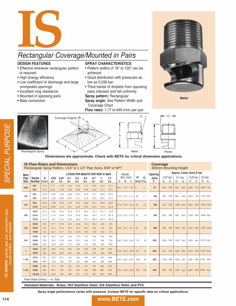
114
SPECIAL PURPOSE
TO O
RD
ER:specify pipe size, connection type,
nozzle number, and material.
www.BETE.com
ISRectangular Coverage/Mounted in PairsDESIGN FEATURES• Effective wherever rectangular patternis required• High energy efficiency• Low coefficient of discharge and largeunimpeded openings• Excellent clog resistance• Mounted in opposing pairs• Male connection
SPRAY CHARACTERISTICS• Pattern widths of 18” to 120” can beachieved• Good distribution with pressures aslow as 0.035 bar• Thick bands of droplets from opposingpairs intersect and fall uniformlySpray pattern: RectangularSpray angle: See Pattern Width and Coverage Chart
Flow rates: 1.77 to 649 l/min per pair
Rectangular Spray
Coverage Diagram
Metal Plastic
Metal
IS Flow Rates and Dimensions Coverage Rectangular Spray Pattern, 1/16" to 1 1/2" Pipe Sizes, BSP or NPT 300mm Mounting Height
Male LITERS PER MINUTE PER PAIR @ BAR Spacing Approx. Cover. (mm) @ bar
Pipe Nozzle K 0.03 0.07 0.1 0.2 0.5 0.7 1 1.5 Dim. (mm) Wt. (g) (mm) 0.07 bar 0.1 bar 0.25 bar 0.5 bar Size Number Factor bar bar bar bar bar bar bar bar A B C Metal Plas. F D E D E D E D E
1/16 IS2 10.2 1.77 2.70 3.22 4.56 7.21 8.53 10.2 12.5
19.1 7.87 7.87 4 2 70 600 450 850 650 1500 750 1800 750 IS3 15.3 2.65 4.04 4.83 6.84 10.8 12.8 15.3 18.7
1/8 IS4 20.4 3.53 5.39 6.45 9.12 14.4 17.1 20.4 25.0
22.2 12.7 11.1 28 7 100 500 350 800 450 1050 750 1150 900 IS6 30.6 5.30 8.09 9.67 13.7 21.6 25.6 30.6 37.4
1/4 IS8 40.8 7.06 10.8 12.9 18.2 28.8 34.1 40.8 49.9
27.0 15.9 14.3 43 11 125 750 450 1000 550 1500 900 1950 1050 IS10 51.0 8.83 13.5 16.1 22.8 36.0 42.6 51.0 62.4
3/8
IS12 61.1 10.6 16.2 19.3 27.3 43.2 51.2 61.1 74.9
31.8 19.1 17.5 57 14 150 650 300 900 500 1350 600 1000 600 IS14 71.3 12.4 18.9 22.6 31.9 50.4 59.7 71.3 87.4
IS16 81.5 14.1 21.6 25.8 36.5 57.7 68.2 81.5 99.9
1/2
IS20 102 17.7 27.0 32.2 45.6 72.1 85.3 102 125
36.5 22.2 22.2 85 28 200 900 300 1500 700 2100 900 2200 1050 IS24 122 21.2 32.4 38.7 54.7 86.5 102 122 150
IS28 143 24.7 37.7 45.1 63.8 101 119 143 175
3/4
IS32 163 28.2 43.1 51.6 72.9 115 136 163 200
44.5 28.6 28.6 170 43 250 1050 300 1500 500 1650 600 2250 650 IS40 204 35.3 53.9 64.5 91.2 144 171 204 250
IS48 245 42.4 64.7 77.3 109 173 205 245 300
1 IS56 285 49.5 75.5 90.2 128 202 239 285 349
55.6 34.9 34.9 227 57 300 750 450 1200 500 1550 600 2250 950 IS64 326 56.5 86.3 103 146 231 273 326 399
1 1/4 IS72 367 63.5 97.1 116 164 259 307 367 449
63.5 44.5 44.5 340 85 350 1200 350 1500 450 2200 500 2700 600 IS80 408 70.6 108 129 182 288 341 408 499
1 1/2
IS88 448 77.7 119 142 201 317 375 448 549
76.2 50.8 50.8 567 142 400 900 350 1200 450 1800 600 3000 950 IS96 489 84.7 129 155 219 346 409 489 599
IS104 530 91.8 140 168 237 375 443 530 649
Flow Rate (l/min ) = K √bar
Standard Materials: Brass, 303 Stainless Steel, 316 Stainless Steel, and PVC
Nozzle
Dimensions are approximate. Check with BETE for critical dimension applications.
Spray angle performance varies with pressure. Contact BETE for specific data on critical applications.

CALL 413-772-0846
Call for the nam
e of your nearest BETE representative.
115
SPECIAL P
URPOSE
www.BETE.com
30° Fan
Low ProfileLPDESIGN FEATURES• Provides effective cleaning with lowwater consumption
• Interchangeable family of shower nozzles
• Self-aligning• Orifice designed for efficient cleaning
SPRAY CHARACTERISTICSSpray patterns: Straight Jet and Flat FanSpray Angles: 0°, 30° and 60°Flow rates: 0.041 to 43.9 gpm
0.162 to 155 l/min
Retaining Ring LP nozzle Gasket
LITERS PER MINUTE @ BAR Available Equivalent
Nozzle Spray Angle K 3 4 5 10 30 Orifice Dia. Number 0° 30° 60° Factor bar bar bar bar bar (mm)
LP0041 0° 0.0937 0.162 0.187 0.209 0.296 0.513 0.4
LP0073 0° 0.167 0.290 0.334 0.374 0.529 0.916 0.6
LP0090 0° 0.205 0.354 0.409 0.458 0.647 1.12 0.7
LP013 0° 0.298 0.517 0.597 0.667 0.943 1.63 0.8
LP023 0° 30° 60° 0.520 0.901 1.04 1.16 1.65 2.85 1.0
LP033 0° 30° 60° 0.744 1.29 1.49 1.66 2.35 4.07 1.2
LP043 0° 30° 60° 0.967 1.68 1.93 2.16 3.06 5.30 1.5
LP08 0° 30° 60° 1.83 3.17 3.66 4.09 5.79 10.0 2.0
LP12 0° 30° 60° 2.82 4.89 5.65 6.32 8.93 15.5 2.5
LP20 0° 30° 60° 4.50 7.79 8.99 10.1 14.2 24.6 3.0
LP31 60° 7.16 12.4 14.3 16.0 22.7 39.2 4.0
LP49 60° 11.2 19.3 22.3 25.0 35.3 61.2 5.0
LP78 60° 17.9 31.0 35.7 40.0 56.5 97.9 6.0
LP99 60° 22.5 38.9 45.0 50.3 71.1 123 7.0
LP124 60° 28.2 48.9 56.5 63.2 89.3 155 8.0
Flow Rate ( l/min ) = K √ bar
Standard Materials: 316 Stainless Steel
LP Flow Rates and Dimensions Fan and Straight Jet, 0°, 30° and 60° Spray Angles
60° Fan0° Fan
Dimensions are approximate. Check with BETE for critical dimension applications.
Spray angle performance varies with pressure. Contact BETE for specific data on critical applications.

116
SPECIAL PURPOSE
TO O
RD
ER:specify pipe size, connection type,
nozzle number, and material.
www.BETE.com
DESIGN FEATURES• High velocity jet• Small physical size• Small orifice size: 0.035mm through3.18mm
• Interchangeable with most other needle-type showers
SPRAY CHARACTERISTICS• Hard driving straight jetFlow rates: 0.075 to 34.1 l/minSpray angle: 0°
TYPICAL APPLICATIONSCleaning, Degreasing,Cleaning Wires and Felts—Pulp andPaper
Small Physical Size Straight Jet
0° Straight JetMale
PSR
LITERS PER MINUTE @ BAR Equivalent Approx.Nozzle K 1 3 5 7 10 15 30 60 Orifice Dim. (mm) Wt.Number Factor bar bar bar bar bar bar bar bar Dia. (mm) A B (g)
PSR03 0.0752 0.075 0.13 0.16 0.19 0.22 0.27 0.37 0.52 0.356PSR11 0.258 0.26 0.43 0.55 0.65 0.76 0.92 1.28 1.77 0.711PSR16 0.393 0.39 0.67 0.85 1.00 1.19 1.44 2.01 2.80 0.838PSR23 0.564 0.56 0.96 1.22 1.44 1.70 2.07 2.89 4.03 1.02PSR40 0.981 0.98 1.66 2.12 2.50 2.96 3.60 5.02 7.00 1.40 14.0 17.5 21.3PSR67 1.644 1.64 2.79 3.56 4.18 4.96 6.03 8.41 11.7 1.78PSR120 2.944 2.94 4.99 6.37 7.49 8.89 10.8 15.1 21.0 2.39PSR195 4.784 4.78 8.11 10.4 12.2 14.4 17.6 24.5 34.1 3.18
Flow Rate (l/min) = K (bar) 0.48
Standard Materials: 316 Stainless Steel.
PSR Flow Rates and DimensionsStraight Jet, 9/16”-24 UNEF Thread
Dimensions are approximate. Check with BETE for critical dimension applications.

CALL 413-772-0846
Call for the nam
e of your nearest BETE representative.
117
SPECIAL P
URPOSE
www.BETE.com
FINZTM
High Impact Fan Air Nozzle• Rugged construction of Ryton® or ABS plastic. Ryton® rated to 149°Cat 3 bar• Maximum operating pressure 7 bar
SPRAY CHARACTERISTICSSpray pattern: FanAir Flow Rates: 7 to 65 Nm3/h at 0.7to 6 bar
DESIGN FEATURES• Controlled wide uniform distribution andhigh impact coverage of compressed air• Can be mounted individually or side-by- side for greater coverage• Efficient air flow rates with unique eductor feature • Safe operation—meets OSHA specificationsfor noise and deadhead pressure• 1/4” male connection is molded to fit eitherNPT or BSP• Up to 2dB quieter than competing designs
FINZHigh Impact Air Nozzle
Air Capacity
Male Nm3/h Approx.NPT Nozzle 0.7 2 4 6 Dim. (mm) Wt.BSP Number bar bar bar bar A B (g)
FZ20 7 12 19 26
1/4” FZ29 11 21 32 43 91 47 28.3
FZ41 15 28 47 65
Standard Materials: Ryton® and ABS plastic.
Ryton is a trademark of Phillips Petroleum company
1/4 NPTor BSP
Dimensions are approximate. Check with BETE for critical dimension applications.

Swivel Joints
DESIGN FEATURES• Adjustable swivel joints allow customalignment of spray nozzles withoutexpensive piping changes• Leak-proof design• Standard materials are brass andstainless steel• Other materials available upon request
SPRAY CHARACTERISTICS• Adjustment angles: From 30° to 45° •Greater control of spray direction forprecise coverage
Adjustable Swivel Jointsaid in aligning spray nozzles
(Optional NF nozzle shown, choose nozzle when ordering)
K 0.7 1 2 3 5 10 15 20 O Metal Only (mm) Wt. (g) S Dia. (mm) A B C D M P
R l ) = K b
Brass, 303 Stainless Steel, 316 Stainless Steel, PVC, Polypropylene and PTFE (1 / and P
C
Dia.(mm) A B C M
R ( l ⁄ ) = K b
Swivel Joint Dimensions
A B C D E Part Inlet Pipe Conn. Outlet Pipe Conn. Overall Length Hex Size Angle of Net Wt.
Number BSP or NPT BSP or NPT (mm) (mm) Adjustment (g)
1/4 X 1/4 SJ 1/4 M 1/4 F 38.1 28.7
3/8 X 1/4 SJ 3/8 M 1/4 F 44.5 38.1 45°
3/8 X 3/8 SJ 3/8 M 3/8 F 45.5 38.1
1/2 X 3/8 SJ 1/2 M 3/8 F 50.8 44.5
1/2 X 1/2 SJ 1/2 M 1/2 F 50.8 44.5 45°
3/4 X 1/2 SJ 3/4 M 1/2 F 54.1 50.8 45°
3/4 X 3/4 SJ 3/4 M 3/4 F 54.1 50.8 45°
M
1/8 X 1/8 SJ 1/8 M 1/8 F 31.8 20.7
1 X 1 SJ 1 M 1 F 76.2 62.0 45°
1 1/4 X 1 1/4 SJ 1 1/4 M 1 1/4 F 88.9 79.5 30°
1 1/2 X 1 1/2 SJ 1 1/2 M 1 1/2 F 98.6 85.9 30°
2 X 2 SJ 2 M 2 F 105 102 40°
F Hex Size
(mm)
25.4
35.1
35.1
41.4
41.4
47.8
47.8
20.7
57.2
73.2
85.9
88.9
111
244
244
366
346
505
465
56.7
967
1899
2679
2920
M
SJ
Dimensions are approximate. Check with BETE for critical dimension applications.
118
SPECIAL PURPOSE
TO O
RD
ER:specify pipe size, connection type,
nozzle number, and material.
www.BETE.com

CALL 413-772-0846
Call for the nam
e of your nearest BETE representative.
119
SPECIAL P
URPOSE
www.BETE.com
Adapters andCouplings
ReducingBushings
Flange Sizes:2” - 12”DN 50 - DN 300
BETE recommends the use ofstrainers to minimize clogging. The1/4” and 3/8” strainers areequipped with 0.25mm-meshscreens, while 1/2” - 2” strainerscome with 0.20mm-mesh screens.Screens with mesh sizes of 0.05,0.06, 0.13 and 0.15mm availableby special order. Screens are easi-ly removed for cleaning. 10 bar rat-ing.
Strainer Sizes: 1/4, 3/8,1/2, 3/4, 1, 1-1/2, 2
Mesh ScreenSizes Opening0.25 mm 0.13 mm0.20 mm 0.18 mm0.13 mm 0.28 mm0.06 mm 0.71 mm0.05 mm 0.86 mm
BETE nozzles are often installedin pipe sizes larger than theirconnection. These bushings willadapt BETE nozzles to existingpiping.
316 stainless steelnickel alloy C-276nickel alloy 625PVCPTFE
316 stainless steelnickel alloy C-276nickel alloy 625PVCPTFEFRP
Bushing Sizes:1/4 x 1/83/8 x 1/8, 1/41/2 x 1/8, 1/4, 3/81 x 1/4, 3/8, 1/2, 3/41-1/2 x 1/4, 1/2, 12 x 1/2, 1
Reducing couplings, socketadapters, elbows, and variousother fittings are available to meetspecific applications.
Wide range of materials available.
Sizes available asrequired
Used to attach nozzles too large tobe threaded. 150# rating, ANSIstandard; 300# and specific ratingsalso available.
Components Materials Sizes
NozzleStrainers
Y-TypeLineStrainers
Flanges
AccessoriesComponents & Sizes
Optional strainer to fit BJ and CWnozzles. All strainers equippedwith 316 stainless steel screens ofvarious mesh sizes.
316 stainless steel US Mesh Sizes:50 (297 µm) (S201)100 (149 µm) (S202)200 (74 µm) (S203)400 (37 µm) (S204)
Bronze body withheavy-duty stainlesssteel wire mesh.
Manifolds Used to cluster many nozzles intoa small physical space
Wide range of materials available
Standard Sizes
Inlet Outlets
1/2” x (7) 3/8”-24 UNF
3/4” x (6) 1/4” or 3/8”
1” x (6) 3/8” or 1/2”

SPECIFYING SPRAY NOZZLESSpray nozzles have three basicfunctions:
The process of choosing a nozzleincludes specifying:
FLOW RATEThe volume of liquid flowingthrough a nozzle depends primari-ly on the difference in fluid pres-sure upstream of its orifice and thepressure into which the nozzle dis-charges (normally that of the at-mosphere). Pressures that are list-ed in the flow rate tables of eachnozzle series are gauge pressures.
Flow rates for pressures not tab-ulated may be calculated using theequation given at the bottom ofeach table. The factor “K” is listedfor each nozzle and has units oflpm/barx.
A nozzle may discharge into avessel where the pressure is notatmospheric. Since the nozzle flowrate is determined by the differen-tial pressure across it, the flow ratemay be calculated by subtracting
the gauge pressure inside the ves-sel from the gauge pressure at thenozzle inlet as shown:
FLUID PROPERTIESSpecific gravity primarily affectsnozzle flow. Flow rates of liquidsdenser than water are lower thanflow rates of water at the samepressure because more energy isrequired to accelerate denser fluids. The following relationshipexists between flow rates (Q)of fluids with different specific gravities:
Viscosity also affects nozzle performance. High viscositiesinhibit atomization. In general,fluids with viscosities greater than100 cP are difficult to atomizeexcept with air-atomizing nozzles.
Engineering Information
Fluid Viscosity Specific Gravity
Water 1cP SG=1
10W-30 Oil 110 cP SG=0.88
Honey 1500 cP SG=1.05
FLUID PROPERTIES(at room temperature)
• meter flow • distribute liquid • break up a liquid stream
into droplets
a.) its flow-rate-versus-pressurecharacteristics (see catalog flowrate tables)
b.) how the droplets will be distri-buted after leaving the nozzle(see spray pattern, pp. 2, 3)
c.) the size of the droplets that willbe produced (contact BETEApplications Engineering ifdroplet size is critical)
d.) the nozzle connection to thefeed pipe (see dimension tables)
e.) the material of construction (seepage 12 for complete list)
l/min = K (BarInlet - BarVessel ) x
Calculate Total Water Flow and Pressure at Pump for Nozzles Operating at 0.5 bar
Total Flow (p. 26, 27) = (1 nozzles)(381 l/min/nozzle) = 381 l/min Pump Pressure Formula: Ppump = Pnozzle + Ppipe losses + rgh/100000
Calculate Pipe Loss: Pipe Friction: (15 m)(0.7 bar/100 m) = 0.11 bar Fitting Loss: (3 elbows)(1.52 m/elbow) = 4.56 m (4.56 m)(0.7 bar/100 m) = 0.03 bar Total Piping Losses: 0.11 bar + 0.03 bar = 0.14 bar Elevation Losses: (1000)(9.81)(12 m) / 100000 = 1.17 bar Ppump = 0.5 bar + 0.14 bar + 1.17 bar = 1.81 bar
Pump must be sized to provide 381 l/min at 1.81 bar
3m
Nozzle:
(1) 2 1/2 MP1250M
DN652 1/2”
12 m = height
www.BETE.comneer
ing.
Eng
inee
ring.
Eng
inee
ring.
Eng
inee
ring.
Eng
inee
ri
120

SYSTEM DESIGNThe piping system that suppliesthe nozzles must be designed to deliver the correct pressure at thenozzle inlet. The following formula
is useful in estimating the pres-sure a pump will have to supply toa nozzle system: where: r = density of fluid (kg/m3) [water = 1000 kg/m3] g = 9.81 m/s2
h = height of nozzle above pump (m) - negative if the nozzle is below the pump p = pressure (bar) A chart of pipe friction losses ispresented on page 125. In using the chart be sure to look at the totalsystem flow if there are multiplenozzles to be supplied by one pipe.Elbows, tees and other pipe fit-tings (see p. 125) also contribute topressure loss and can be signifi-cant, especially in short, convolu-ted runs.
SPRAY ANGLEThe spray angle chosen for aparticular application depends onthe coverage required. The spray angle for spiral noz-zles is relatively stable over a widerange of pressures, while the spray
angle for whirl nozzles tends todecrease as the pressure is increased.For additional information seepage 124.
NOZZLE SPRAY PATTERNThe term “Spray Pattern”describes the location and spraydensity of the liquid emitted froma nozzle. Two examples of patternmeasurement are shown above.The height of the curve at anypoint is the spray density in unitsof LPM/m2.
DROPLET SIZEDroplet size is often critical. Manyprocesses such as gas scrubbingdepend on exposing the maximumpossible amount of liquid surfaceto a gas stream. Other applica-tions require that the droplets beas large as possible, such as whenthe spray must project into a fastmoving gas stream.
Exposing the maximum surfacearea requires breaking the liquidinto droplets as small as possible.To get an idea of how this works,imagine a cube of water with a vol-ume of 1 m3. This cube has a sur-face area of 6 m2. If we now split itin two, we expose some of theinner surface and increase the totalsurface area to 8 m2. Atomizingthe liquid into spheres 1 mm (1,000microns) in diameter wouldincrease the surface area of thisgallon of liquid to 6000 m2.
A nozzle actually produces arange of droplet sizes from thesolid liquid stream. Since it isinconvenient to list all the sizesproduced, droplet size (inmicrons) is usually expressed by amean or median diameter. Anunderstanding of diameter termsis essential.
PPump = PNozzle + PPipe Losses +rgh
100000
Radial Distance (mm)
LPM / m
2LPM / m
2
Radial Distance (mm)
neering. Engineering. Engineering. Engineering. Engineeriwww.BETE.com 121

The following definitions aregiven for the most frequently usedmean and median diameters:
Arithmetic MeanDiameter (D10)• The average of the diameters of all
the droplets in the spray sample.Volume Mean Diameter (D30)• The diameter of a droplet whose
volume, if multiplied by the totalnumber of droplets, will equalthe total volume of the sample.
Sauter Mean Diameter (D32): • The diameter of a droplet whose
ratio of volume to surface area isequal to that of the completespray sample.
Mass (Volume) MedianDiameter (DV05):• The diameter which divides the
mass (or volume) of the spray intotwo equal halves. Thus 1/2 of thetotal mass is made up of droplets
with diameters smaller than thisnumber and the other half withdiameters that are larger.The Sauter Mean Diameter is one
of the most useful ways to charac-terize a spray. The ratio of volumeto surface area for the Sauter Meanis the same as that ratio for theentire spray volume. For this rea-son, the use of the Sauter Mean ispreferred for process calculations.
Whirl nozzles generally producelarger droplets than spiral nozzles,
and air-atomizing nozzles such asthe XA or SpiralAir Series typicallyproduce the smallest droplets of all.
It is sometimes useful to predictthe effect a change in pressure willhave on the droplet size produced
by the nozzle. For single fluid noz-zles the following equation may beused for modest changes in pressure.TROUBLESHOOTING BASICSThe following are some of thethings to look for when a system is not performing as intended:
Nozzle Wear or Corrosion• may cause excessive flow rate
due to enlarged passages• may increase droplet size• degrades spray patternNozzle Clogging• low flow rates• poor spray pattern
Inadequate Pipe Size• excessive pipe pressure losses
leading to low nozzle pressures• high velocities in headers that
disrupt fluid entering the nozzleIncorrect Nozzle Location• poor gas/liquid contact in
scrubbers and quenchers• poor area coverageIncorrect Nozzle for Application• drop size too small or too large• incorrect pattern type
Careful system design and selec-tion of the proper BETE nozzlewill minimize spray problems.
D2D1
P2P1( )-0.3=
neer
ing.
Eng
inee
ring.
Eng
inee
ring.
Eng
inee
ring.
Eng
inee
riRELATIVE DROP SIZE BY NOZZLE SERIES
www.BETE.com
The BETE Droplet Analyzer is capable of characterizing non-spherical droplets like those seen in this actual image.
Actual droplet images captured using the BETE Model 700Spray Analysis System.
122
Research & D
evelopment. Research &
Developm
ent. ResearchRESEARCH & DEVELOPMENTBETE’s state-of-the-art Spray Laboratory plays a key role in sup-porting both product R&D and ourcustomer service network. Equipped with sophisticatedvideo-image processing and digi-tal analysis technology, the SprayLab makes possible rapid nozzledevelopment and evaluation. The Spray Lab is also availableon a contract basis to provide con-fidential, quantitative evaluationof nozzle performance. Industrialapplications for contract testingrange from comparative nozzleperformance testing to develop-ment of proprietary designs. Thesecapabilities allow our customers tooptimize process performancewhile minimizing capital andoperating costs—a winning combi-nation in today’s competitive glo-bal marketplace.
Spray Laboratory Capabilities • Flow rate (water) measure-
ments from 0.04 to 7500 l/min • Flow rate (air) measurements
from 0.5 to 2550 Nm3/h • Pressure measurements to 210
bar • Automated drop size distribu-
tion measurement from lessthan 2 to greater than 15,000microns
• Computerized spray distribu-tion analysis
• Two-fluid capabilities up to2550 Nm3/h air / 3000 l/m water
• 9 m x 15 m x 7 m high testarea
DROPLET ANALYSISFrustrated by the limited capabili-ties of laser-based instruments,BETE developed the Model 700Video Particle Analyzer. This flexible system allows BETE to
characterize the difficult sprayscontaining significant numbers oflarge and non-spherical dropsoften encountered in industrialapplications. The Model 700 is avideo-imaging system combining aCCD video camera, microscopelens, fast strobed xenon lightsource, and image processinghardware and software.PATTERN DISTRIBUTION ANALYSISThe BETE Patternator is a uniquedigital video system for accuratelyanalyzing the volumetric distribu-tion of liquid emitted from a noz-zle. The system uses a standardtube patternator combined withBETE's custom shape recognitionand timing software. From thisdigitized information, spray density and effective spray anglesare calculated. Because data collection and ana-lyses are handled by computer, the device is very well-suited forhandling the large amount of datarequired for nozzle developmentand assessment programs.
Consistently and accuratelyselecting appropriate samplingpositions is extremely importantwhen performing drop size analy-sis. The challenge lies in samplingthe spray in such a way that thenumber and locations of the indi-vidual tests chosen present a rea-sonable representation of theentire spray. Recognizing this,BETE has integrated the patterna-tor with the Model 700 analyzer ona calibrated X-Y-Z positioner anddeveloped a number of samplingprotocols for droplet size analysis.These protocols ensure that thereported drop size distributionsmost accurately reflect the overall
spray performance, thus allowinga high degree of repeatability and confidence. COMPUTER MODELING ANDSIMULATIONThere are instances when duplicat-ing the operating environment inthe spray lab is impossible. Whenthe nozzle is to be used in a high-temperature or pressure environ-ment or sprayed in a high velocitygas stream, BETE ApplicationsEngineers use computer modelingand simulation software devel-oped in-house to assist in specify-ing the proper nozzle.
Spray-modeling has also beenused to predict spray drift fromcooling ponds and dust suppres-sion systems and estimating evap-oration rates from disposal ponds.
Working with engineering com-panies and consulting groups,BETE Engineering taps this model-ing and simulation technology tooffer customized spray nozzlesolutions to some of the most vex-ing problems facing industrytoday.
INDUSTRY COOPERATIVEDEVELOPMENT PROGRAMSBETE has worked closely withmajor industries in research anddevelopment programs addressingpersonnel safety and environmen-tal protection issues.
BETE has provided technicalexpertise, computer simulation,testing, and nozzle prototypes in avariety of projects, including:
• fire control aboard offshoredrilling platforms
• toxic gas control • oil spill cleanup • reducing CFC use in the semi-
conductor industry
Research & Development
www.BETE.com 123

neer
ing.
Eng
inee
ring.
Eng
inee
ring.
Eng
inee
ring.
Eng
inee
riSpray CoverageSPRAY ANGLE TERMSFour terms are commonly used todescribe spray coverage:
Spray Angle:(A) The included angle of the sprayas measured close to the nozzleorifice. Since the droplets areimmediately acted upon byexternal forces (gravity andmoving gases, for example), thismeasurement is useful only fordetermining spray coverage closeto the nozzle. The spray angles lis-ted for nozzles in this catalog areangles at the nozzle, measured atthe nozzle’s design pressure.Actual Spray Coverage:
The actual coverage at a speci-fied distance from the nozzle.Effective Spray Angle:
The angle calculated from theactual coverage at a distance
.Theoretical Spray Coverage:
The coverage at distance ifthe spray moved in a straight line.
EXAMPLES:Problem: To achieve a 200mmdiameter spray coverage from anozzle mounted 150mm from thetarget, what spray angle would be required?Solution: 70° Spray Angle
Problem: How far from the targetshould a nozzle with a 110° sprayangle be mounted in order toachieve a 550mm diameter spray?Solution: Approximately 200mm.(Actual coverage will be less thantheoretical coverage listed in the table.)
NOTE: For applications wherecoverage is critical, contact BETEApplications Engineering using theApplications Intake form on page 128.
(B)(D)
(C)(B)
(D)
(D)
(E)
THEORETICAL SPRAY COVERAGE (E) IN MILLIMETERS
Included Spray Distance From Nozzle Orifice (D) (mm)
Angle (A) 50 75 100 150 200 300 400 600 800 1000
10° 9 13 17 26 35 52 70 105 140 175
20° 18 26 35 53 71 106 141 212 282 353
30° 27 40 54 80 107 161 214 322 429 536
40° 36 55 73 109 146 218 291 437 582 728
50° 47 70 93 140 187 280 373 560 746 933
60° 58 87 115 173 231 346 462 693 924 1155
70° 70 105 140 210 280 420 560 840 1120 1400
80° 84 126 168 252 336 503 671 1007 1343 1678
90° 100 150 200 300 400 600 800 1200 1600 2000
100° 119 179 238 358 477 715 953 1430 1907 2384
110° 143 214 286 428 571 857 1143 1714 2285
120° 173 260 346 520 693 1039 1386 2078
130° 214 322 429 643 858 1287 1716
140° 275 412 549 824 1099 1648 2198
150° 373 560 746 1120 1493 2239
170° 1143 1715 2286
NOTE: Data shown is theoretical and does not take into consideration theeffects of gravity, gas flow, or high pressure operation.
www.BETE.com124

neering. Engineering. Engineering. Engineering. EngineeriWater Flow Data
www.BETE.com 125

neer
ing.
Eng
inee
ring.
Eng
inee
ring.
Eng
inee
ring.
Eng
inee
rin
126
Notes
www.BETE.com

127www.BETE.com
Pipe Dimensions & WeightsNominalPipe Size OD Schedule
WallThickness ID Weight
NPS [DN] in [mm] mm mm kg/m
1/8
[6]
0.405
[10.3]
10 10S 1.24 7.8 0.28STD 40 40S 1.73 6.8 0.36XS 80 80S 2.41 5.5 0.47
1/4
[8]
0.540
[13.7]
10 10S 1.65 10.4 0.49STD 40 40S 2.24 9.3 0.63XS 80 80S 3.02 7.7 0.80
3/8
[10]
0.675
[17.1]
10 10S 1.65 13.8 0.63STD 40 40S 2.31 12.5 0.85XS 80 80S 3.20 10.7 1.10
1/2
[15]
0.840
[21.3]
5 5S 1.65 18.0 0.8010 10S 2.11 17.1 1.00
STD 40 40S 2.77 15.8 1.27XS 80 80S 3.73 13.9 1.62
160 4.78 11.8 1.95XX 7.47 6.4 2.55
3/4
[20]
1.050
[26.7]
5 5S 1.65 23.4 1.0210 10S 2.11 22.5 1.28
STD 40 40S 2.87 20.9 1.68XS 80 80S 3.91 18.9 2.19
160 5.56 15.5 2.89XX 7.82 11.0 3.63
1
[25]
1.315
[33.4]
5 5S 1.65 30.1 1.2910 10S 2.77 27.9 2.09
STD 40 40S 3.38 26.6 2.50XS 80 80S 4.55 24.3 3.23
160 6.35 20.7 4.23XX 9.09 15.2 5.45
1-1/4
[32]
1.660
[42.2]
5 5S 1.65 38.9 1.6510 10S 2.77 36.6 2.69
STD 40 40S 3.56 35.1 3.38XS 80 80S 4.85 32.5 4.46
160 6.35 29.5 5.60XX 9.70 22.8 7.76
1-1/2
[40]
1.900
[48.3]
5 5S 1.65 45.0 1.9010 10S 2.77 42.7 3.10
STD 40 40S 3.68 40.9 4.04XS 80 80S 5.08 38.1 5.40
160 7.14 34.0 7.23XX 10.16 27.9 9.54
2
[50]
2.375
[60.3]
5 5S 1.65 57.0 2.3910 10S 2.77 54.8 3.93
STD 40 40S 3.91 52.5 5.44XS 80 80S 5.54 49.3 7.47
160 8.74 42.9 11.10XX 11.07 38.2 13.44
3
[80]
3.500
[88.9]
5 5S 2.11 84.7 4.5110 10S 3.05 82.8 6.45
STD 40 40S 5.49 77.9 11.27XS 80 80S 7.62 73.7 15.26
160 11.13 66.7 21.32XX 15.24 58.4 27.65
3-1/2
[90]
4.000
[101.6]
5 5S 2.11 97.4 5.1710 10S 3.05 95.5 7.40
STD 40 40S 5.74 90.1 13.56XS 80 80S 8.08 85.5 18.61XX 16.15 69.3 34.00
NominalPipe Size OD Schedule
WallThickness ID Weight
NPS [DN] in [mm] in in lb/ft
4
[100]
4.500
[114.3]
5 5S 2.11 110.1 5.83
10 10S 3.05 108.2 8.35
STD 40 40S 6.02 102.3 16.06
XS 80 80S 8.56 97.2 22.30
120 11.13 92.1 28.28
160 13.49 87.3 33.50
XX 17.12 80.1 40.99
6
[150]
6.625
[168.3]
5 5S 2.77 162.7 11.29
10 10S 3.40 161.5 13.83
STD 40 40S 7.11 154.1 28.24
XS 80 80S 10.97 146.3 42.52
120 14.27 139.7 54.16
160 18.26 131.8 67.49
XX 21.95 124.4 79.11
8
[200]
8.625
[219.1]
5S 2.77 213.5 14.75
10 10S 3.76 211.6 19.94
20 6.35 206.4 33.28
30 7.04 205.0 36.75
STD 40 40S 8.18 202.7 42.49
60 10.31 198.5 53.04
XS 80 80S 12.70 193.7 64.57
100 15.09 188.9 75.82
120 18.26 182.6 90.35
140 20.62 177.8 100.83
XX 22.23 174.6 107.78
160 23.01 173.1 111.15
10
[250]
10.750
[273.1]
5S 3.40 266.2 22.61
10S 4.19 264.7 27.76
20 6.35 260.4 41.72
30 7.80 257.5 50.96
STD 40 40S 9.27 254.5 60.25
XS 60 80S 12.70 247.7 81.46
80 15.09 242.9 95.88
100 18.26 236.5 114.63
120 21.44 230.2 132.88
140 25.40 222.3 154.97
160 28.58 215.9 172.10
12
[300]
12.750
[323.9]
5S 3.96 315.9 31.23
10S 4.57 314.7 35.96
20 6.35 311.2 49.67
30 8.38 307.1 65.14
STD 40S 9.53 304.8 73.76
40 10.31 303.2 79.65
XS 80S 12.70 298.5 97.35
60 14.27 295.3 108.87
80 17.48 288.9 131.90
100 21.44 281.0 159.71
120 25.40 273.1 186.75
140 28.58 266.7 207.86
160 33.32 257.2 238.51
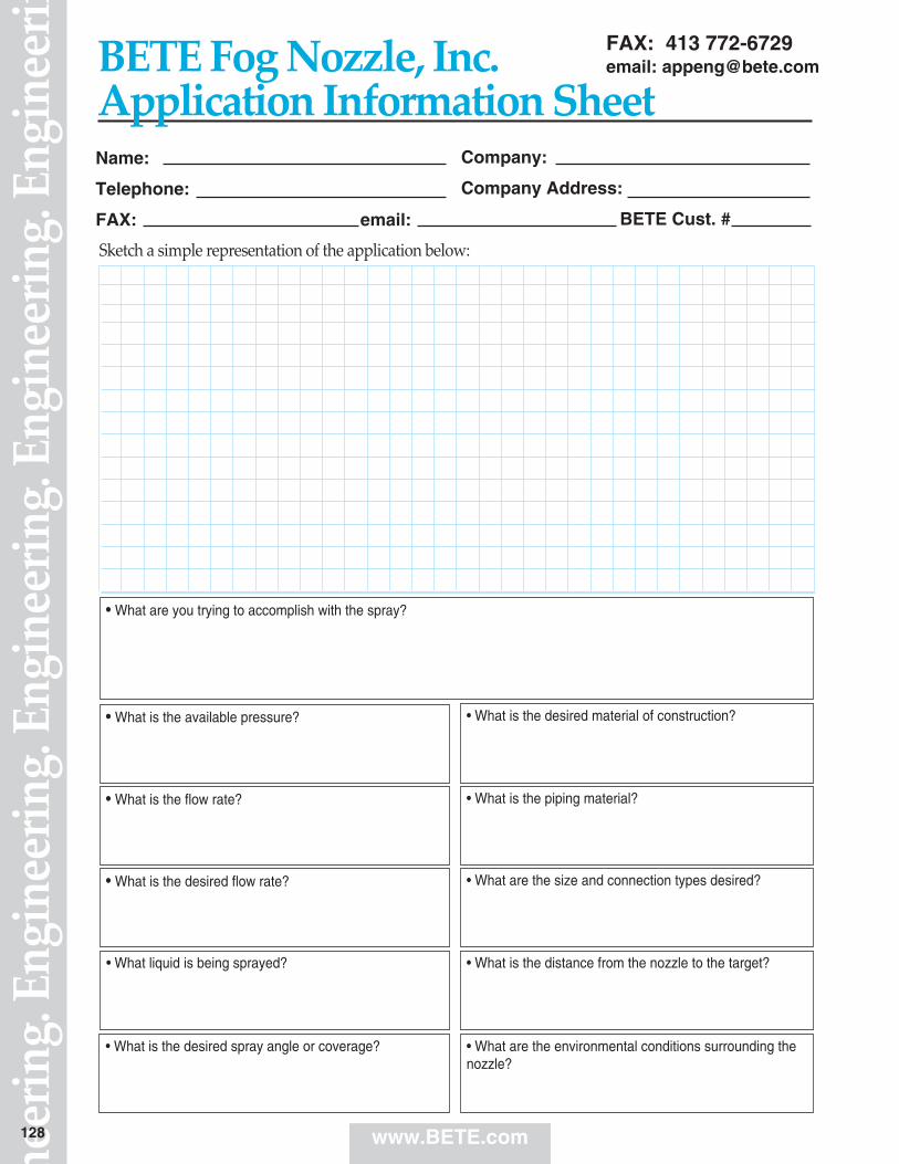
www.BETE.com
Sketch a simple representation of the application below:
Name:
Telephone:
FAX: email:
Company:
Company Address:
BETE Cust. #
• What is the piping material?
• What liquid is being sprayed?
• What are the environmental conditions surrounding thenozzle?
• What is the available pressure?
• What is the desired spray angle or coverage?
• What is the desired material of construction?
FAX: 413 772-6729email: [email protected]
• What are you trying to accomplish with the spray?
• What is the desired flow rate?
• What is the flow rate?
• What are the size and connection types desired?
• What is the distance from the nozzle to the target?
BETE Fog Nozzle, Inc.Application Information Sheet
neer
ing.
Eng
inee
ring.
Eng
inee
ring.
Eng
inee
ring.
Eng
inee
rin
128

Q = Flow rate
Q = K (P)x
P = (Q)1/X
K
(Q2)-
Q1= (P2)X
P1
P = Pressure SG= Specific Gravity
(Q2)Q1 = Ö SG1
SG2
Vessel with internal pressure:
l/min = K (Pinlet - PVessel )x
Terms and Conditions.Prices quoted are FOB, Greenfield, MA. Terms are Net 30 days for approved accounts.Minimum order is $50.00 net. A restocking charge of 30% will apply for standard productaccepted for return up to one year from the date of purchase. BETE FOG NOZZLE reservesthe right to charge interest on past-due accounts. No goods may be returned without priorauthorization. Non-Standard items are not subject to return.
BETE FOG NOZZLE reserves the right to make changes in specifications or design at anytime without notice. Illustrations shown in this catalog are for information only.Warranty—all goods are warranteed for good workmanship in accordance with industrystandard and will perform in accordance with the products’ specification.Limitation of Liability—BETE’s liability shall be limited to the value of the product billedarising from a purchase order.
Conversion DataMULTIPLY BY TO OBTAINfeet/sec 18.29 meters/min
feet of water 0.0295 atmospheres
feet of water 0.884 inches of mercury
feet of water 0.433 psi
gallons 3785 cm3
gallons 0.1337 ft3
gallons 0.83267 imperial gallons
gallons 3.785 liters
gallons/min 0.06309 liters/sec
imperial gallons 1.2 gallons
horsepower 1.014 horsepower (metric)
horsepower 33,000 foot pounds/min
horsepower 746 Watts
inches 2.54 centimeters
kg/cm2 14.22 psi
kiloWatts 1.340 horsepower
liters 1000 cm3
liters 0.264 gallons
liters 0.22 imperial gallons
liters 33.8 ounces (fluid)
meters 3.281 feet
microns (µm) 0.0394 thousandth of an inch
miles/hr 44.7 centimeters/sec
miles/hr 1.467 feet/sec
millimeters 0.0394 inches
psi 0.068 atmospheres
psi 0.06895 bar
psi 2.307 feet of water
psi 0.0703 kg/cm2
psi 6.895 kPa
Conversion DataMULTIPLY BY TO OBTAINatmospheres 1.013 bar
atmospheres 33.931 feet of water
atmospheres 1.0332 kg/cm2
atmospheres 101.3 kiloPascals (kPa)
atmospheres 14.696 psi
bar 100 kPa
bar 14.5 psi
barrels (oil) 42 gallons
centimeters 0.3937 inches
centiStokes Sp. gravity centiPoise
cm3 0.061 in3
cm3 0.000264 gallons
cm3 0.001 liters
ft3 1728 inches
ft3 0.02832 m3
ft3 7.48 gallons
ft3 28.32 liters
ft3 (water) 62.43 pounds (water)
in3 16.39 cm3
in3 0.00433 gallons
in3 0.164 liters
m3 35.31 ft3
m3 61.024 in3
m3 264.2 gallons
m3 1000 liters
degree (angle) 60 minutes
degree (Celsius) (°C x 1.8) +32 degree (Fahrenheit)
degree (Fahrenheit) (°F-32) x 5/9 degree (Celsius)
feet 0.3048 meters
feet/sec 30.48 centimeters/sec
Dropsize System Design
(D2D1
) = (P2)-0.3 PPump = PNozzle + PPipe Losses + rh
100000P1
www.BETE.com
Nozzle Exponent Nozzle ExponentSeries x Series xBJ 0.50 PJ 0.50CW 0.47 PSR 0.50FF 0.50 SC 0.47IS 0.50 SPN 0.50L 0.50 ST 0.50LP 0.50 STXP 0.50MaxiPass 0.47 TC 0.46MPL 0.43 TD/TDL 0.50MicroWhirl 0.50 TF 0.50N 0.50 TFXP 0.50NC 0.47 TH, THW 0.50NCJ 0.47 TW 0.50NCK 0.47 WL 0.47NCS 0.47 WT 0.50NF 0.50 WTX 0.50P 0.50 WTZ 0.50
Conversions & Equations

50 Greenfield StreetGreenfield, MA 01301T (413) 772-0846 F (413) 772-6729Email: [email protected]
BETE Fog Nozzle, Inc.
PERFORMANCE THROUGH ENGINEERING
ABSORPTION • ADDITIVES • AERATION • AIR AND STEAM • AIR CONDITIONING • AIR NOZZLES
• BIODIESEL • BLOWOFF NOZZLES • CLEAN-IN-PLACE NOZZLES • CLOG-RESISTANT NOZZLES
• COATING • CONCRETE CURING • COOLING • DISTRIBUTION • DRYING • DUST CONTROL
• ETCHING • EVAPORATIVE COOLING • EVAPORATIVE DISPOSAL • FIRE PROTECTION • FLUE GAS
DESULPHURIZATION • FOAM CONTROL • FOG NOZZLES • FOOD PROCESSING • GAS SCRUBBING
• HUMIDIFICATION • LUBRICATION • MIST ELIMINATOR WASH • MISTING • MIXING
EDUCTORS • MOISTENING • ODOR CONTROL • PACKING • PARTS WASHING
• PETROLEUM PROCESSING • POLLUTION CONTROL • PULP BLEACHING • QUENCH
• ROLL COOLING • SCRUBBING • SPRAY DRYING • TANK WASHING • WASTEWATER TREATMENT
0218 2K 0218METRIC
www.bete.com


![NUMERICAL ANALYSIS OF THERMAL SPRAY COATING PROCESSraiith.iith.ac.in/766/1/ME10M09.pdf · thermal conductivity [6]. 1.3 Different Methods of Thermal Spraying There are different types](https://static.fdocuments.net/doc/165x107/606b6207416417364335f80a/numerical-analysis-of-thermal-spray-coating-thermal-conductivity-6-13-different.jpg)