
Betacam Sx DNW-7P Maintenance Manual
124
DIGITAL CAMCORDER DNW-7/7P DNW-9WS/9WSP DNW-90/90P DNW-90WS/90WSP MAINTENANCE MANUAL Part 1 1st Edition (Revised 4) Serial No. 10001 and Higher (DNW-7/9WS/90/90WS) Serial No. 40001 and Higher (DNW-7P/9WSP/90P/90WSP)
Transcript of Betacam Sx DNW-7P Maintenance Manual

DIGITAL CAMCORDER
DNW-7/7PDNW-9WS/9WSPDNW-90/90PDNW-90WS/90WSP
MAINTENANCE MANUAL Part 1
1st Edition (Revised 4)Serial No. 10001 and Higher(DNW-7/9WS/90/90WS)Serial No. 40001 and Higher(DNW-7P/9WSP/90P/90WSP)

DNW-7/90/90WS
! WARNINGThis manual is intended for qualified service personnel only.To reduce the risk of electric shock, fire or injury, do not perform any servicing other than thatcontained in the operating instructions unless you are qualified to do so. Refer all servicing toqualified service personnel.
! WARNUNGDie Anleitung ist nur für qualifiziertes Fachpersonal bestimmt.Alle Wartungsarbeiten dürfen nur von qualifiziertem Fachpersonal ausgeführt werden. Um dieGefahr eines elektrischen Schlages, Feuergefahr und Verletzungen zu vermeiden, sind beiWartungsarbeiten strikt die Angaben in der Anleitung zu befolgen. Andere als die angegebenWartungsarbeiten dürfen nur von Personen ausgeführt werden, die eine spezielle Befähigungdazu besitzen.
! AVERTISSEMENTCe manual est destiné uniquement aux personnes compétentes en charge de l’entretien. Afinde réduire les risques de décharge électrique, d’incendie ou de blessure n’effectuer que lesréparations indiquées dans le mode d’emploi à moins d’être qualifié pour en effectuer d’autres.Pour toute réparation faire appel à une personne compétente uniquement.
X-RAY RADIATION WARNINGBe sure that parts replacement in the high voltage blockand adjustments made to the high voltage circuits arecarried out precisely in accordance with the proceduresgiven in this manual.

DNW-7/90/90WS 1 (P)
For the customers in the NetherlandsVoor de klanten in Nederland
Hoe u de batterijen moet verwijderen, leest u in de vandeze handleiding deel 2.
Gooi de batterij niet weg maar lever deze in als kleinchemisch afval (KCA).
Für Kunden in Deutschland
Entsorgungshinweis: Bitte werfen Sie nur entladeneBatterien in die Sammelboxen beim Handel oder denKommunen. Entladen sind Batterien in der Regel dann,wenn das Gerät abschaltet und signalisiert “Batterieleer” oder nach längerer Gebrauchsdauer der Batterien“nicht mehr einwandfrei funktioniert”. Umsicherzugehen, kleben Sie die Batteriepole z.B. miteinem Klebestreifen ab oder geben Sie die Batterieneinzeln in einen Plastikbeutel.


1DNW-7/90/90WS
Table of Contents
Manual Structure
Purpose of this manual .............................................................................................. 5
Contents ..................................................................................................................... 5
Relative manual ......................................................................................................... 6
1. Service Overview
1-1. Operating Conditions .................................................................................. 1-1
1-2. Supplied Accessories .................................................................................. 1-1
1-3. Location of Main Parts and Function of Printed Circuit Boards ................ 1-21-3-1. Location and Function of Printed Circuit Boards ...................... 1-21-3-2. Location of Main Parts ............................................................... 1-41-3-3. Location and Function of Sensors .............................................. 1-6
1-4. Matching Connectors .................................................................................. 1-8
1-5. Signal Input and Output .............................................................................. 1-9
1-6. Removal/Installation of Cabinet ............................................................... 1-12
1-7. Removal/Installation of Cassette Compartment ........................................ 1-14
1-8. Pulling Out and Inserting the Plug-in Boards ........................................... 1-15
1-9. Switch/Slit Land Settings on the Boards ................................................... 1-161-9-1. AXM-14 Board ........................................................................ 1-161-9-2. CNB-1 Board ........................................................................... 1-171-9-3. DVP-1 Board ............................................................................ 1-181-9-4. DVP-2 Board ............................................................................ 1-191-9-5. TC-80 Board ............................................................................. 1-201-9-6. MDC-5 Board ........................................................................... 1-221-9-7. DCP-31/1 Board ....................................................................... 1-231-9-8. TG-207/164 Board (for DNW-9WS/9WSP/90/90P/90WS/
90WSP only) ............................................................................ 1-24
1-10. Ejecting the Cassette Tape Manually ........................................................ 1-25
1-11. Inserting the Cassette Tape when the Outside Panel is Removed ............ 1-26
1-12. Cleaning when the Heads are Clogged ..................................................... 1-261-12-1. Cleaning by Cleaning Tape ...................................................... 1-261-12-2. Cleaning by Cleaning Cloth ..................................................... 1-27
1-13. Backup Battery .......................................................................................... 1-28
1-14. Removal/Installation of Flexible Card Wires ........................................... 1-28
1-15. Fixtures ...................................................................................................... 1-291-15-1. Extension Boards ..................................................................... 1-291-15-2. Fixtures ..................................................................................... 1-30

2 DNW-7/90/90WS
2. Error Code
2-1. Error Code ................................................................................................... 2-12-1-1. Warning Indicators ..................................................................... 2-12-1-2. Error Codes ................................................................................ 2-1
2-2. Error Messages ............................................................................................ 2-2
3. Maintenance Mode
3-1. Setup Menu ................................................................................................. 3-1
3-2. DIAG Menu .............................................................................................. 3-24
4. Block Diagram and Circuit Description
5. Electrical Alignment
5-1. General Information for Electrical Adjustment .......................................... 5-15-1-1. Note for Adjustment ................................................................... 5-15-1-2. Equipment/Fixtures .................................................................... 5-15-1-3. Initial Setting for Switches ......................................................... 5-1
5-2. ENC Level Adjustment ............................................................................... 5-2
5-3. TEST OUT Adjustment .............................................................................. 5-2
5-4. VA Gain Adjustment ................................................................................... 5-3
5-5. White Shading Adjustment ......................................................................... 5-4
5-6. Gamma Correction Adjustment .................................................................. 5-5
5-7. Black Set Adjustment .................................................................................. 5-6
5-8. Flare Adjustment ......................................................................................... 5-6
5-9. Manual Knee and White Clip Adjustments ................................................ 5-7
5-10. Crispening Adjustment ................................................................................ 5-8
5-11. Level Depandent Adjustment ...................................................................... 5-8
5-12. H/V Ratio Adjustment ................................................................................. 5-9
5-13. Detail Level Adjustment ............................................................................. 5-9
5-14. Skin Tone Adjustment ............................................................................... 5-10
5-15. Zebra Adjustment ...................................................................................... 5-11
5-16. Automatic Iris Adjustment ........................................................................ 5-12

3DNW-7/90/90WS
6. Electrical Alignment (Only for DNW-9WS/9WSP/90WS/90WSP)
6-1. General Information for Electrical Adjustment .......................................... 6-16-1-1. Note for Adjustment ................................................................... 6-16-1-2. Equipment/Fixtures .................................................................... 6-16-1-3. Initial Setting for Switches ......................................................... 6-2
6-2. ENC Level Adjustment ............................................................................... 6-3
6-3. TEST OUT Level Adjustment .................................................................... 6-3
6-4. VA Gain Adjustment ................................................................................... 6-4
6-5. White Shading Adjustment ......................................................................... 6-5
6-6. Gamma Correction Adjustment .................................................................. 6-6
6-7. Black Set Adjustment .................................................................................. 6-7
6-8. Flare Adjustment ......................................................................................... 6-7
6-9. Manual Knee and White Clip Adjustments ................................................ 6-8
6-10. Crispening Adjustment (16:9) ..................................................................... 6-9
6-11. Level Depandent Adjustment (16:9) ........................................................... 6-9
6-12. H/V Ratio Adjustment (16:9) .................................................................... 6-10
6-13. Detail Level Adjustment (16:9) ................................................................ 6-10
6-14. Crispening Adjustment (4:3) ..................................................................... 6-11
6-15. Level Depandent Adjustment (4:3) ........................................................... 6-11
6-16. H/V Ratio Adjustment (4:3) ...................................................................... 6-12
6-17. Detail Level Adjustment (4:3) .................................................................. 6-12
6-18. Skin Tone Adjustment ............................................................................... 6-13
6-19. Zebra Adjustment ...................................................................................... 6-14
6-20. Automatic Iris Adjustment ........................................................................ 6-15
7. Periodic Maintenance and Inspection
7-1. Cleaning ...................................................................................................... 7-17-1-1. General Information for Cleaning .............................................. 7-17-1-2. Cleaning of Tape Running Surface of Upper Drum
and Video Heads ........................................................................ 7-37-1-3. Cleaning of Tape Running Surface of Lower Drum
and Lead Surface ........................................................................ 7-47-1-4. Stationary Heads Cleaning ......................................................... 7-57-1-5. Cleaning of Tape Running System and Tape Cleaner ............... 7-6
7-2. Periodic Check ............................................................................................ 7-77-2-1. Hours Meter ............................................................................... 7-77-2-2. Periodic Check List .................................................................... 7-8
7-3. Cares After Using at Special Environment ................................................. 7-9


5DNW-7/90/90WS
Purpose of this manualThis manual is maintenance manual of Digital Camcorder DNW-7/7P/9WS/9WSP/90/90P/90WS/90WSP.This manual describes the maintenance information of this unit, and the informationon primary services such as the error message and cleaning procedures.
ContentsThe following is a summary of the sections for understanding the contents of thismanual.
Section 1 Service OverviewExplains the locations of main part, the functions of printed circuit board, theremoval and installation of cabinet, and the measures against trouble.
Section 2 Error CodeExplains the error messages.
Section 3 Maintenance ModeExplains the SETUP menu (ENG mode) and DIAG menu of this unit.
Section 4 Block Diagram and Outline of CircuitDescribes the overall block diagram and the circuit descriptions.
Section 5 Electrical AlignmentExplains the general information for electrical adjustments and the electrical adjust-ments of camera system.
Section 6 Electrical Alignment (Only for DNW-90WS/90WSP)Explains the general information for electrical adjustments and the electrical adjust-ments of camera system.
Section 7 Periodic Maintenance and InspectionExplains the cleaning procedures and periodic checks.
Manual Structure

6 DNW-7/90/90WS
Relative manualBesides this “Maintenance Manual Part 1”, the following manuals are available forthis unit.
..... Operation Manual (Supplied with this unit.)This manual is necessary for application and operation of this unit.
..... Maintenance Manual Part 2 (Not supplied with this unit.)This manual describes the information items (adjustments, board layouts, sche-matic diagrams, detailed parts list, etc.) that premise the service based on parts.If this manual is required, please contact Sony’s service organization.
..... BVF-V10/V10CE or BVF-V20W/V20WCEMaintenance Manual (Not supplied with this unit.)This manual describes the service information of the viewfinder.If this manual is required, please contact Sony's service organization.

1-1DNW-7/90/90WS
Section 1Service Overview
1-1. Operating Conditions
Operating temperature : 0 to 40 dCHumidity : 25 to 85 % (Relative humidity)Storage temperature : _20 to 60 dC
Use under special environment (Measure for cold area)The unit is guaranteed its operation under the temperatureof 0 to 40 dC. When the unit is used under 0 dC, cover-cloth against the cold is recommended to use.
1-2. Supplied Accessories
Description Part No. Quantity
Shoulder belt A-6772-374-B 1
Microphone 1-542-295-11 1
Connector cover 3-748-142-01 4
Screw B2 x 4 7-621-772-10 3
Operation manual (Printed manual) _ 1
Operation manual (CD-ROM) _ 1
Maintenance manual Part 1 _ 1

1-2 DNW-7/90/90WS
1-3. Location of Main Parts and Function of Printed Circuit Boards1-3-1. Location and Function of Printed Circuit Boards
1-3. Location of Main Parts and Function of Printed Circuit Boards
1-3-1. Location and Function of Printed Circuit Boards
TC-80DCP-31/1
DVP-2DVP-1MDC-5
CI-12
RX-26RE-119RE-118HP-70
CN-1193(RC-61)
MB-627CNB-1
AXM-14CO-22IO-117
PS-390
AIF-8MA-68SW-808
SW-789
BC-31/25(BC-32/26)
SW-780
CN-1183
BI-96
DR-387/291
PSW-33
LP-86TG-206/161
(TG-207/164)ES-11KY-293MDR-1
PS-390PS-390
VA-191/167PA-228/186
HN-224
SW-823
AL-40 DC-88 DC-88 AL-40
DC-87

1-3DNW-7/90/90WS
System Board name Function name
CCD BLOCK BI-96 CCD Imager (R, G, B)
CN-1183 Connector Board for BI-96
DR-387/291 CCD Driver
PA-228/186 Pre-amp(Sample & Hold)
TG-206/161 *1 Timing Generator
TG-207/164 *2 Timing Generator
VA-191/167 Video Amp
CAMERA/VIDEO CN-1193 *3 Connector Board for DCP-31/1
RC-61 *4 Rate (16:9 to 4:3) Converter
DCP-31/1 Camera Processor
DVP-1 RF, Digital Audio Processor, Timing Clock Generator, System Controller for VTR Block
DVP-2 Digital Bit Reduction Decoder, Digital Encoder, Digital Decoder
ES-11 Composite Encoder
TC-80 Analog Audio Processor, Time Code Generator
DRUM/SERVO HN-224 Harness, TC Amp
MDC-5 Servo Controller
MDR-1 Drum Motor Driver
MICROPHONE AIF-8 Lens Control, Mic Amp
MA-68 Camera Mic Pre-amp
SW-789 Mic Level, Auto White/Black Switch, VTR Start/Stop Switch, Shutter On/Off Select Switch
POWER SUPPLY DC-87 Battery DC Filter
PS-390 Power Supply (Light)
RE-118 Regulator, Switching Control
RE-119 Regulator
CONNECTOR BOX AL-40 Audio CH-2 Line Out Amp
AXM-14 Connector (AUDIO IN/OUT), Audio Pre-amp
CNB-1 Circuit Breaker, Audio CH-1 Line Out Amp
CO-22 Connector (VBS OUT)
DC-88 External DC Filter
IO-117 Connector (GEN LOCK IN, TEST OUT, TC IN, TC OUT)
OTHERS CI-12 40-pin Adaptor Interface
HP-70 Earphone
KY-293 Function Key
LP-86 Back Tally, Back Tally Switch
PSW-33 Power Switch
RX-26 Audio Pre-amp for Wireless Microphone
SW-780 Switch Panel
SW-808 Rotary Encoder Switch
SW-823 Menu and Light Auto/Manual Switch
MB-627 Mother Board
*1: For DNW-7/7P only*2: For DNW-9WS/9WSP/90/90P/90WS/90WSP only*3: For DNW-7/7P/90/90P only*4: For DNW-9WS/9WSP/90WS/90WSP only
1-3. Location of Main Parts and Function of Printed Circuit Boards1-3-1. Location and Function of Printed Circuit Boards

1-4 DNW-7/90/90WS
1-3-2. Location of Main Parts
Mechanical deck
1-3. Location of Main Parts and Function of Printed Circuit Boards1-3-2. Location of Main Parts
37
6
8
9
0
!-
54
![!]
@]
!'
@[
!.
@\
@'
@;
#-
!=
!\!;
@.
@,
!,
@/
@-@=
#/
2
1

1-5DNW-7/90/90WS
1 : CCD block2 : Fan motor3 : Tension regulator arm4 : S5 tape guide5 : Tension regulator guide (S4 tape guide)6 : S3 tape guide7 : Full erase head8 : Tape cleaner9 : CTL head0 : S2 tape guide (on S slider)!- : S1 tape guide (on S slider)!= : Slip ring![ : Drum!] : Video head cleaner!\ : Brush!; : T1 tape guide (on T slider)!' : T2 tape guide (on T slider)!, : TC head!. : Capstan motor@/ : Manual eject knob@- : Threading motor@= : Pinch roller@[ : T3 tape guide@] : T4 tape guide@\ : Timing belt@; : T reel table@' : T soft brake@, : Gear@. : S soft brake#/ : S reel table#- : Tension regulator band
1-3. Location of Main Parts and Function of Printed Circuit Boards1-3-2. Location of Main Parts

1-6 DNW-7/90/90WS
1-3-3. Location and Function of Sensors
Mechanical deck
1-3. Location of Main Parts and Function of Printed Circuit Boards1-3-3. Location and Function of Sensors
1
ID6
ID4
ID3ID1
ID2
2 3 4
6
78
9
!/
!-
!=
5
ID5

1-7DNW-7/90/90WS
1 : Temperature sensorThis sensor detects the temperature and then the fan motor is rotated.
2 : Cassette-in sensorThis sensor detects the existence of a cassette.
3 : REC inhibit sensorThis sensor detects the REC inhibiting plug of the cassette tape.
4 : Tape end sensorThis sensor detects the end of the tape that runs in the forward direction.
5 : Full top sensorThis sensor detects whether the cassette tape is the full top.
6 : Condensation sensorThis sensor detects whether the dew condensation occurs in the unit.
7 : Tape top sensorThis sensor detects the end of the tape that runs in the reverse direction.
8 : Function cam sensorThis sensor detects the rotation position of a cam.
9 : Take-up reel table rotating sensorThis sensor detects the rotation of the take-up reel table. The FG output signal of this sensor is inputto a servo circuit so as to calculate the winding diameter of the tape.
0 : Cassette lock sensor (switch)This sensor detects that the cassette compartment was locked.
!- : Cassette ID sensorsID1 : Tape type sensor
This sensor detects the tape type either an oxide or a metal.ID2 : Tape thickness sensor
Using a tub on the back side of the cassette tape, this sensor detects the thickness of thetape wound on a cassette tape that is being inserted into the unit.
ID3 : Reel hub diameter sensorThe reel hub diameter of a cassette tape varies depending on the length of the tapewound on the cassette tape. The reel hub diameter sensor detects the reel hub diameterby the tab on the back side of the cassette tape.
ID4 to ID6 : Tape format sensorsThese sensors detect the type of the cassette tape (for Betacam SX, Betacam SPand so on).
!= : Supply reel table rotating sensorThis sensor detects the rotation of the supply reel table. The FG output signal of this sensor is inputto a servo circuit so as to calculate the winding diameter of the tape.
1-3. Location of Main Parts and Function of Printed Circuit Boards1-3-3. Location and Function of Sensors

1-8 DNW-7/90/90WS
1-4. Matching Connectors
When external cables are connected to the connector during maintenance, the hardware listed below (orthe equivalents) must be used.
Panel Indication Matching Connector/Cable
Name of Connector/Cable Part No.
AUDIO IN CH-1/CH-2 XLR 3-pin, male 1-508-084-00 (for SY)XLR 3-pin, female 1-508-083-00 (for J)
AUDIO OUT Audio cable SONY CCXA-53 or equivalent(XLR 5-pin _ XLR 3-pin, 2m)
GENLOCK IN BNC 1-560-069-11TC INTC OUTTEST OUTVIDEO OUT
DC IN XLR 4-pin, female 1-508-362-00
DC OUT 12 V DIN 4-pin, male 1-566-425-11
MIC IN +48 V XLR 3-pin, male 1-508-084-00
REMOTE 6-pin, male 1-560-078-00
EARPHONE Mini jack Standard product
LIGHT Power tap [OE] ANTONBAUER 33710 or equivalent
1-4. Matching Connectors

1-9DNW-7/90/90WS
1-5. Signal Input and Output
INPUTGENLOCK IN 1.0 V p-p, 75 ZTC IN 0.5 V to 18 V p-p, 10 kZMIC IN _60 dBuAUDIO IN CH-1, CH-2 _60 dBu/+4 dBu
(0 dBu = 0.775 Vrms)
DC IN: XLR 4-pin, male<External View>
Pin No. Signal
1 GND
2 _
3 _
4 EXT DC (DC 11 to 17 V)
DC OUT 12V: DIN 4-pin, female<External View>
Pin No. Signal
1 UNREG GND
2 _
3 _
4 UNREG +12 V (11 to 17 V, 0.1 A MAX)
OUTPUTTEST OUT 1.0 V p-p, 75 Z, unbalancedTC OUT 1.0 V p-p, 75 ZVIDEO OUT 1.0 V p-p, 75 Z, unbalancedEARPHONE _∞ to _18 dBu, adjustable, 8 ZAUDIO OUT 0 dBm (600 Z terminated)
BATT IN: 5-pin, male<External View>
Pin No. Signal
1 BATT IN (_)
2 BATT IND
3 BATT REM
4 LIGHT CONT
5 BATT IN (+)
AUDIO OUT: XLR5-pin, male<External View>
Pin No. Signal
1 GND
2 CH1 (X)
3 CH1 (Y)
4 CH2 (X)
5 CH2 (Y)
1
2 3
41 2 3 4 5
1
23
454 1
3 2
1-5. Signal Input and Output

1-10 DNW-7/90/90WS
REMOTE: 6-pin, female<External View>
Pin No. Signal
1 SD (RM)
2 SD (RM) I/O
3 UNREG GND
4 RM TEST (X)
5 RM TEST (G)
6 UNREG +12 V
LIGHT: 2-pin, female<External View>
Pin No. Signal
1 LIGHT +12 V (30W MAX)
2 GND
14
9
18
8
20
12
3
13 17
6
5
4 3
2
1
VF: 20-pin, female<External View>
Pin No. Signal
1 VTR SAVE
2 ABNORMAL
3 16:9/4:3
4 REC (L)
5 COLOR VF DET
6 CCIR/EIA
7 DISPLAY ON
8 G TALLY
9 _
10 Y (X)
11 ZEBRA ON
12 VIDEO (X)
13 AUDIO CTL
14 B-Y (X)
15 R-Y (X)
16 BATT IND
17 REC/TALLY
18 +9.3 V
19 GND
20 UNREG
12
1-5. Signal Input and Output

1-11DNW-7/90/90WS
LENS: 12-pin, female<External View>
Pin No. Signal
1 RET (SW)
2 VTR TRIG
3 LENS GND
4 AUTO +5 V
5 IRIS CONT
6 UNREG +12 V
7 IRIS POSITION
8 REMOTE/LOCAL
9 EXTENDER
10 ZOOM POSITION
11 N.C
12 N.C
1
2
34
8
5 6
7
9
10
11
12
1-5. Signal Input and Output
1-12 DNW-7/90/90WS
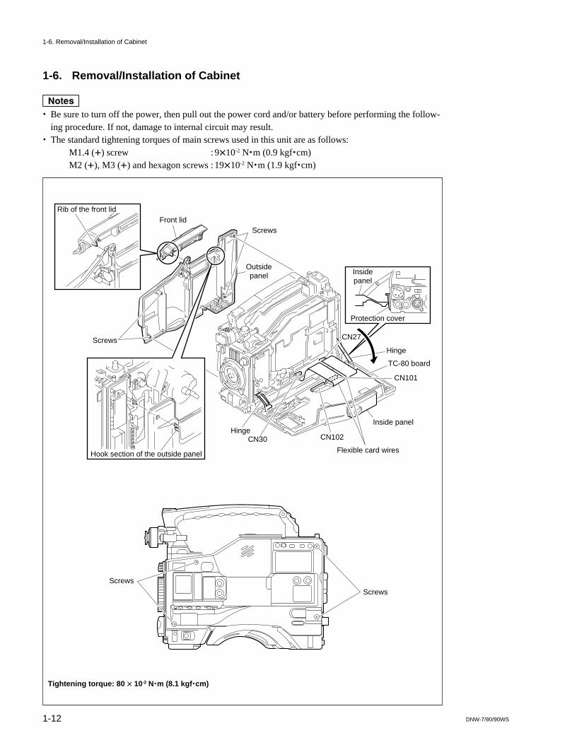
1-6. Removal/Installation of Cabinet
m. Be sure to turn off the power, then pull out the power cord and/or battery before performing the follow-
ing procedure. If not, damage to internal circuit may result.. The standard tightening torques of main screws used in this unit are as follows:
M1.4 (+) screw : 9x10⁻² N.m (0.9 kgf.cm)M2 (+), M3 (+) and hexagon screws : 19x10-2 N.m (1.9 kgf.cm)
Tightening torque: 80 x 10-2 N.m (8.1 kgf.cm)
1-6. Removal/Installation of Cabinet
Rib of the front lidFront lid
Screws
Screws
Outsidepanel
Hook section of the outside panel Flexible card wires
Inside panelHinge
Hinge
Protection cover
Insidepanel
CN30 CN102
CN101
CN27
TC-80 board
Screws
Screws

1-13DNW-7/90/90WS
Front LidLoosen the two screws fully and remove the front lid.(Stoppers are provided for these screws.)
nInsert the rib of the front lid firmly into the groove duringinstallation.
Outside panel1. Remove the front lid.2. Loosen the four screws fully and remove the outside
panel.(Stoppers are provided for these screws.)nInsert the hook section of the outside panel firmly intothe guide shaft of the cassette compartment duringinstallation.
Inside Panel1. Loosen the four screws fully and open the inside panel
in the direction indicated by the arrow. (Stoppers areprovided for these screws.)m. Be careful not to bend the two flexible wires inten-
tionally.. When opening, hook the inside panel on the protec-
tion cover of connector box to avoid damage to thecabinet.
2. Disconnect connectors CN27 and CN30 on the MB-627 board.
3. Remove the flexible card wires from connectorsCN101 and CN102 on the TC-80 board. (Refer tosection 1-14.)
4. Remove the two hinges.
Connector Box
Removal
1. Remove the front lid, inside panel, and outside panel.2. Loosen the two screws fully and slide the shoulder pad
forward. (Stoppers are provided for these screws.)3. Remove the four screws, then remove the connector box.
4. Disconnect connectors CN104 and CN105 on theCNB-1 board.
Cautions during Installation
1. Connect the connector CN20 on the MB-627 boardsecurely to the connector CN101 on the CNB-1 boardin the connector box.
2. Connect the connectors CN104 and CN105 on the CNB-1 board, after attaching the connector box to the unit.
3. Be careful not to get caught the harness in the rib.
1-6. Removal/Installation of Cabinet
Connector box
CN104
CN105
CN101
MB-627 board
CN20
CNB-1 board
Showlder pad
Screws
Screws (B3 x 8)Tightening torque80 x 10-2 N.m(8.1 kgf.cm)
Screws (B3 x 8)Tightening torque80 x 10-2 N.m(8.1 kgf.cm)
Connector box

1-14 DNW-7/90/90WS
1-7. Removal/Installation of CassetteCompartment
m. Be sure to turn off the power, then pull out the power
cord and/or battery before performing the followingprocedure. If not, damage to internal circuit may result.
. The cassette compartment can be removed even if itcomes up or goes down.
Removal
1. Remove the front lid and outside panel.(Refer to section 1-6.)
2. Remove the three screws, hold the position of thecassette compartment shown in the figure, and removeit in the direction indicated by the arrow.
Installation
1. Adjust the position of the joint arm so that the clear-ance between the white roller’s outer circumference ofa joint arm and the end face of the mechanical deckassembly is 0.5 mm.
2. Raise the white lock roller of the cassette compartmentso that it comes up.
1-7. Removal/Installation of Cassette Compartment
Cassette compartment
(Omit the illustration of the frame)
Mechanical deck assembly
Screws(M 1.4 x 3.5)
Screws(M 1.4 x 3.5)
White lock roller
0.5 mm
White roller
Joint arm

1-15DNW-7/90/90WS
3. Move the cam plate (A) on the right side of thecassette compartment in the direction of the arrow withfingers as far as it will go.
4. Hold the position of the cassette compartment shownin the figure and attach two cassette guide pins in thechassis so that they are put in the round holes of thestage.At that time, confirm that the other white roller of thejoint arm positioned in step 1 is put in the notch of thecam plate (A) on the right side.
5. Push the lever of the cassette compartment andconfirm that the stage smoothly moves up and down.If not, re-confirm steps 1 to 4.
6. Attach the cassette compartment with three screws.
1-8. Pulling Out and Inserting the Plug-in Boards
Be careful attention so that the parts on the board are notdamaged and the board is positioned and oriented correctlywhen pulling out and inserting the plug-in boards.Replace each board after confirming the setting of switchesand slit lands. (Refer to section 1-9.)For the adjustment after board replacement, refer to “5.General Information for Electrical Alignment” of theMaintenance Manual Part 2 Vol-1.
Pulling out the plug-in board
1. Open the levers and disconnect the plug-in board fromthe connectors on the MB-627 board.
2. Pull out the plug-in board.
Inserting the plug-in board
1. Insert the plug-in board along the board guide rails.2. Connect the connectors of the plug-in board to the
connectors on the MB-627 board securely. Be sure toinsert the plug-in board with levers in a horizonalposition.
Cam plate (A)
Notch of thecam plate (A)
Screws(M 1.4 x 3.5)
Screws(M 1.4 x 3.5)Lever
Stage
Otherwhite roller
White roller(step1)
Joint arm
Notch
Cassette guide pin
Round holeof the stage
Cassetteguide pin
1-7. Removal/Installation of Cassette Compartment1-8. Pulling Out and Inserting the Plug-in Boards
Plug-in board
Levers

1-16 DNW-7/90/90WS
1-9. Switch/Slit Land Settings on the Boards
nFor the factory-use switch and slit land, do not change the switch and slit land settings.
1-9-1. AXM-14 Board
Slit Lands
Ref. No. Name Description Factory setting
SL300 AUDIO OUT Select OPEN : Outputs from the XLR 5-pin connector. OPENSHORT: Outputs from the XLR 3-pin connector. *2
SL301 AUDIO OUT Select OPEN : Outputs from the XLR 3-pin connector. *2 SHORT *1
SHORT: Outputs from the XLR 5-pin connector.
*1: This slit land is short-circuited by the traces on the board. Therefore, the traces must be cut using a knife when the setting ischanged.
*2: The modification of the unit is necessary for change of the connector.
1
2
ABC
SL300
SL301
AXM-14 B Side
1-9. Switch/Slit Land Settings on the Boards1-9-1. AXM-14 Board

1-17DNW-7/90/90WS
1-9-2. CNB-1 Board
Slit Land
Ref. No. Description Factory setting
SL1 Destination Select OPEN : For except Japan OPEN (for except Japan)SHORT : For Japan SHORT (for Japan)
nSet SL1 according to the destination during board replacement.
SL101 Power supply selectSlit short : Supplies electric power from the battery to the unit automatically when the external power
supply voltage is lower than the battery voltage.Slit open : Supplies electric power from the external power supply to the unit irrespective of the voltage
level of the external power supply when the electric power is supplied from the external powersupply.
Power supply select
Slit Input voltage Input voltageEXT DC > BATT EXT DC < BATT
SL101 SHORT EXT DC BATT
OPEN EXT DC EXT DC(Factory setting)
CNB-1 A Side
3
4
2
1
CBA
SL1
SL101
1-9. Switch/Slit Land Settings on the Boards1-9-2. CNB-1 Board

1-18 DNW-7/90/90WS
1
2
3
4
5
GFEDC
B
A
S1 S3S2
6
DVP-1 A Side
1-9-3. DVP-1 Board
Switches
Ref. No Name Description Factory setting
S1-1 Destination Select OFF: NTSC OFF (for NTSC)ON : PAL ON (for PAL)
S1-2 Model Select OFF: DNW-7/7P/9WS/9WSP/90/90P/90WS/ OFF90WSP
ON : DNV-5
S1-2 to 8 _ Not used OFF
S2-1 to 3 _ Factory use OFF
S2-4 Model Select ON : DNW-9WS/9WSP/90/90P/90WS/90WSP ON (for DNW-9WS/9WSP/90/90P/90WS/90WSP)
OFF : DNV-5, DNW-7/7P OFF (for DNV-5,DNW-7/7P)
S3-1 to 8 _ Not used OFF
Slit lands
Ref. No. Description Factory setting
SL1 Factory use OPEN
SL2 Factory use SHORT
SL3 Factory use SHORT
DVP-1 B Side
1
2
3
4
5
EF D C B A
SL1 SL3
SL2
G
6
1-9. Switch/Slit Land Settings on the Boards1-9-3. DVP-1 Board

1-19DNW-7/90/90WS
1-9-4. DVP-2 Board
Switches
Ref. No. Name Description Factory setting
S401-1 _ Factory use OPEN
S401-2 _ Not used OPEN
Slit Lands
Ref. No. Description Factory setting
SL601 Factory use OPEN
SL602 Factory use SHORT
1-9. Switch/Slit Land Settings on the Boards1-9-4. DVP-2 Board
1
2
3
4
5
FEDC
A
B
6
S401SL601
SL602
DVP-2 A Side

1-20 DNW-7/90/90WS
TC-80 B Side
1K
2
3
4
5
6
7
JHGF
EDCB
A
S102
S204S104
S501
S601
SL301
SL401SL402
SL103
SL206SL205
SL203SL202
SL106
SL105
SL704SL703SL702SL706
SL507
SL607
SL508
SL608
SL601SL602
SL501SL502
SL506
SL102SL302
SL707SL905
1-9-5. TC-80 Board
Switches
Ref. No. Name Description Factory setting
S102 CH-1 Front MIC Selects whether to control CH-1 audio OFFLEVEL Control level of rear input by using the front
MIC LEVEL control.ON : EnablesOFF: Disables
S104 CH-1 Limiter CH-1 Limiter OFF/ON OFF
S204 CH-2 Limiter CH-2 Limiter OFF/ON OFF
S501 CH-1 Output Limiter CH-1 Output Limiter OFF/ON (+10 dB limit) ON
S601 CH-2 Output Limiter CH-2 Output Limiter OFF/ON (+10 dB limit) ON
Slit LandsHeadroom Level Select for Input Signal (Factory setting:20 dB)
Audio Channel Ref. No. Head room (dB)
20 18 16
CH1 *1 SL102 OPEN SHORT OPEN
SL103 OPEN OPEN SHORT
AGC CH1 SL105 OPEN OPEN SHORT
SL106 OPEN SHORT OPEN
CH2 *1 SL202 OPEN SHORT OPEN
SL203 OPEN OPEN SHORT
AGC CH2 SL205 OPEN OPEN SHORT
SL206 OPEN SHORT OPEN
AGC CH3 SL301 OPEN SHORT OPEN
SL302 OPEN OPEN SHORT
AGC CH4 SL401 OPEN SHORT OPEN
SL402 OPEN OPEN SHORT
*1: This switch setting is enable to select when the AUDIO SELECT switch on the inside panel is selected MANU.
1-9. Switch/Slit Land Settings on the Boards1-9-5. TC-80 Board

1-21DNW-7/90/90WS
Headroom Level Select for Output Signal (Factory setting:20 dB)
Audio Channel Ref. No. Head room (dB)
20 18 16
CH1 SL501 *1 OPEN SHORT OPEN
SL502 *1 OPEN OPEN SHORT
CH2 SL601 *1 OPEN SHORT OPEN
SL602 *1 OPEN OPEN SHORT
*1: TC-80 board number suffix : -12 and higher
Ref. No. Name Description Factory setting
SL506 CH1 Monitor Select OPEN : Selects the output signal of the SHORT*2
CH-1 outputs connector using theMONITOR select switch on the insidepanel. Set SL506 and SL905 are thedifferent positions.
SHORT : Outputs the CH-1 signal to the CH-1output connector.
*2: This slit land is short-circuited by the traces on the board. Therefore, the traces must be cut using a knife when the setting ischanged.
Setting the Audio Output Level (Factory setting:0 dBm)
Audio Channel Ref. No. Output Level (dBm)
+++++4 0
CH1 SL507 SHORT OPEN Set the same positions.
SL508 SHORT OPEN
CH2 SL607 SHORT OPEN Set the same positions.
SL608 SHORT OPEN
Ref. No Name Description Factory setting
SL702 _ Factory use SHORT
SL703 _ Factory use SHORT
SL704 _ Factory use SHORT
SL706 _ Factory use SHORT
SL707 _ Factory use SHORT
SL905 CH1 Monitor Select SHORT : Selects the output signal of the CH-1 OPENoutput connector using the MONITORselect switch on the inside panel.Set SL506 and SL905 are thedifferent positions.
OPEN : Outputs the CH-1 signal to the CH-1 output connector.
1-9. Switch/Slit Land Settings on the Boards1-9-5. TC-80 Board

1-22 DNW-7/90/90WS
1-9-6. MDC-5 Board
Switches
Ref. No. Description Factory setting
S108 Adjustment Mode Select _
S109 Adjustment Start _
S110-1 Adjustment Mode ON/OFF OFF
S110-2 Tracking Adjustment OFF
S111-1 Board Adjustment Mode OFF/ON OFF
S111-2 Not used OFF
S300 Factory use _
Slit Lands
Ref. No. Description Factory setting
SL100 Factory use SHORT
SL102 Factory use SHORT
SL103 Factory use OPEN
SL300 Factory use SHORT
MDC-5 B Side
3
4
5
6
7
8
H G F E D1
BA 2
C
S110
J
S109S108
1-9. Switch/Slit Land Settings on the Boards1-9-6. MDC-5 Board
3
4
5
6
7
8
HGFED1
BA2
C
S111S300
MDC-5 A Side
J
SL300
SL102 SL100
SL103

1-23DNW-7/90/90WS
1
2
3
4
5
FEDC
A
DCP-31/1 A Side
S2
S1S4
B
6
1-9-7. DCP-31/1 Board
Switches
Ref. No. Name Description Factory setting
S1 ENG Disable Select ON : Disables OFFOFF : Enables
S2 Character Select Selects whether to display the character 2on the viewfinder and TEST OUT connector.1: Both viewfinder and TEST OUT connector2: Viewfinder only3: TEST OUT connector only(For the character to be displayed on neitherthe viewfinder nor TEST OUT connector,set off the DISPLAY switch of the viewfinder.)
S4-1 _ Factory use OFF
S4-2 Remote Connector ON : Connects except RM-P9 and VA-DN1. OFFOFF : Connects RM-P9 or VA-DN1.
S4-3 VF CAM Select ON : Outputs the camera signal on the viewfinder OFFwhen the OUTPUT switch is set BARS.
OFF : Outputs the color bars signal on the viewfinderwhen the OUTPUT switch is set BARS.
S4-4 CAM Mode OFF : Uses the VTR START button as the INCOM OFFTALK ON button.
ON : Uses the VTR START button as the RET 2button.
(When S4-4 is set ON, use the VTR SAVE/STBYswitch as the INCOM TALK ON button.)
S4-5 to 7 _ Not used OFF
S4-8 Data reset ON : Resets in the setting menu OFFwhen the power is turn on.
OFF : Uses in normal times.
1-9. Switch/Slit Land Settings on the Boards1-9-7. DCP-31/1 Board

1-24 DNW-7/90/90WS
2
A
S1
S2
1
BC
TG-207/164 B Side
1-9-8. TG-207/164 Board (for DNW-9WS/9WSP/90/90P/90WS/90WSP only)
Switch
Ref. No. Name Description
S1 Model Select 4:316:9
S2 *1 Model Select FITIT
*1: Board suffix -13 and higher. (When board suffix is -11 or -12, not use for DNW-9WS/9WSP.)
Model Select
Model S1 S2
DNW-9WS/9WSP 16:9 IT
DNW-90/90P 4:3 FIT
DNW-90WS/90WSP 16:9 FIT
1-9. Switch/Slit Land Settings on the Boards1-9-8. TG-207/164 Board (for DNW-9WS/9WSP/90/90P/90WS/90WSP only)

1-25DNW-7/90/90WS
1-10. Ejecting the Cassette TapeManually
nBe sure to turn off the power, then pull out the power cordand/or battery before performing the following procedure.If not, damage to internal circuit may result.
1. Open the cover of the outside panel shown in thefigure.
2. Turn the gear clockwise while pushing a gear down-ward until the front lid opens using a Philips screw-driver. Then confirm that the tape is taken up thecassette reel.
3. The front lid opens. The cassette tape can then beejected.
m. Never turn the gear no further after the front lid
opened.If the gear is turned moreover, gear phase will be out oforder, and then the opeation timing of the cleaning rollerwill be shifted.When performing the phase adjustment of the gear, referto section 3-3-4. Timing Belt (Threading) Replacementof maintenance manual part2 volume1.
. Closing the front lidIn the state mentioned above, the front lid cannot beclosed and locked. Turn on the power, then close thefront lid.
If the above operation cannot be executed,perform the following procedures.
1. Remove the front lid and outside panel.(Refer to section 1-6.)
2. Put the cassette compartment into the cassette-up statewith the cassette lid of the cassette tape raised.(For more details, refer to section 1-7.)
3. Remove the cassette tape taking care that the tape doesnot get damage.
1-10. Ejecting the Cassette Tape Manually
Turn while pushing(clockwise)
Cover
2
1
Front lid

1-26 DNW-7/90/90WS
1-11. Inserting the Cassette Tape whenthe Outside Panel is Removed
1. Place the cassette compartment into the up state.(Refer to section 1-7.)
2. Insert a cassette tape in the cassette compartment.3. Insert a screwdriver into the hole of cassette compart-
ment shown in the figure, move it in the directionindicated by the arrow until it locks into place.
nNever push the lid arm (L) when placing the cassettecompartment into the down state. The lid arm (L) becomedeformed, and the front cover can not be locked when theoutside panel is installed.
1-12. Cleaning when the Heads areClogged
If the video heads are clogged, clean the heads as thefollowing procedures.If the video heads are still clogged after cleaning by thecleaning tape, clean them by cleaning cloth.
1-12-1. Cleaning by Cleaning Tape
nMake sure to use the cleaning tape BCT-5CLN. If clean-ing is performed by other kind of cleaning tape, unusualwearing or damage of the video heads, may occur.
1. Insert the cleaning tape BCT-5CLN in the unit.2. Press the PLAY button.
Head cleaning starts.3. After 5 seconds, press the EJECT button.4. The cleaning tape will be ejected.
nBe sure to take out the cleaning tape after cleaning toavoid damages to the heads.
5. Confirm that the head clog is clear.
1-11. Inserting the Cassette Tape when the Outside Panel is Removed1-12. Cleaning when the Heads are Clogged1-12-1. Cleaning by Cleaning Tape
Lid arm (L)Screwdriver
Hole of the cassettecompartment
Cassette compartment

1-27DNW-7/90/90WS
1-12-2. Cleaning by Cleaning Cloth
m. Turn off the power before cleaning.. Each block in the mechanical deck consist of precision
parts and are adjusted precisely. Be careful not todamage each part and to apply an excessive force duringcleaning.
. Do not touch the greased portions during cleaning. Ifgrease attaches to a cleaning cloth, replace the cleaningcloth by a new one. If a cleaning cloth smeared withgrease is used, grease may attach to the places where itshould not.
. Do not insert a cassette tape before a cleaning fluidcompletely evaporate after cleaning.
. Be sure to rotate the upper drum counterclockwiseduring cleaning. Clean the upper drum along thecircumference. If the upper drum is cleaned in thevertical direction, the rotary heads may be damaged.
Tools. Cleaning cloth : 3-184-527-01. Cleaning fluid : 9-919-573-01nNever use a cotton swab to clean the rotary heads.
Cleaning the Video Heads
1. Remove the front lid and outside panel.(Refer to section 1-6.)
2. Press the cleaning cloth moistened with cleaning fluidslightly against the position of the rotary headsinstallation height.
3. Rotate the upper drum slowly in the counterclockwisedirection by hands and clean it.
4. After cleaning, wipe the upper drum with dry cleaningcloth.
Cleaning the Stationary Heads and Tape Guides
1. Remove the front lid and outside panel.(Refer to section 1-6.)
2. Wipe the stationary heads and tape guides using thecleaning cloth moistened with cleaning fluid.
3. After cleaning, wipe the stationary heads and tapeguides with dry cleaning cloth.
Upper dram
Cleaning cloth
Video heads
1-12. Cleaning when the Heads are Clogged1-12-2. Cleaning by Cleaning Cloth

1-28 DNW-7/90/90WS
1-13. Backup Battery
The lithium battery for data backup operation is mountedon the TC-80 board. Replace the lithium battery every fiveyears. For more details of the replacement, refer to “1-3.Lithium Battery Replacement” of the Maintenance ManualPart 2 Vol-1.
1-14. Removal/Installation of FlexibleCard Wires
m. Be sure to turn off the power, then pull out the power
cord and/or battery before performing the followingprocedure. If not, damage to internal circuit may result.
. Two 30-pin flexible card wires are used between theMB-627 and the TC-80 boards. Be careful not to breakthese flexible card wires. This shortens the wire life.
Removal
1. Slide portions A in the direction indicated by thearrows, unlock it, then pull out the flexible card wire.
Installation
1. Check that the conductive surface of the flexible cardwire is not soiled with dust.
2. Slide portions A in the direction indicated by thearrows and insert the flexible card wire tightly intoeach connector with the conductive surface of thesewire put down.nBe careful not to insert the flexible card wire oblique-ly.
3. Slide portions A in the reverse direction of the arrowsand lock each connector.
1-13. Backup Battery1-14. Removal/Installation of Flexible Card Wires
Flexible card wire
Flexible card wires
Portion A

1-29DNW-7/90/90WS
DVP-1 board
DCP-31/1 board Stays
Hook
Hook
1-15. Fixtures
1-15-1. Extension Boards
Extension boards are optionally available to check andadjust the boards in the table below. Use the extensionboards in the procedure below, then perform to check andadjust the boards.
Extension board Board to be checked and adjusted
EX-501 DVP-1, DVP-2
DCP-31/1, ES-11, CN-1193 *1, RC-61 *2
EX-541, EX-542 MDC-5
*1: For DNW-7/7P/90/90P only*2: For DNW-9WS/9WSP/90WS/90WSP only
Using the EX-501 board
1. Remove the board to be extended (DVP-1 or DCP-31/1 board).
2. Connect the EX-501 board to the connector on theMB-627 board.
3. Connect the board (DVP-1 or DCP-31/1) to be extend-ed to the EX-501 board.
nWhen to remove the connected board from the EX-501board, insert the tip of a flat-blade screwdriver into thesection marked with “EJECT”, turn the screwdriver, andremove the board.
Using the EX-541 and EX-542 boards
1. Remove the DVP-1 and DCP-31/1 boards.2. Remove the eight screws, then remove the shield cover
on the MDC-5 board.3. Connect the EX-541 board to connectors CN3 and
CN4 on the MB-627 board.4. Connect the EX-542 board to connectors CN1 and
CN2 on the MB-627 board.
5. Connect the DVP-1 board to the EX-541 board.6. Connect the DCP-31/1 board to the EX-542 board.7. Install the two stays in the hooks and fix the DVP-1
and DCP-31/1 boards shown in the figure.
nWhen to remove the connected boards from the EX-541and EX-542 boards, insert the tip of a flat-blade screwdriv-er in the section marked with “EJECT”, turn the screwdriv-er, and remove the board.
1-15. Fixtures1-15-1. Extension Boards
EX-541 board
EX-542 board
MDC-5 board
EJECT
EJECT
EX-501 board

1-30 DNW-7/90/90WS
1-15-2. Fixtures
Fig. No. Description Name For use
1 A-8315-553-A HN-255 Assembly (TP Tool) Video tracking adjustment
A-8315-552-A IF-701Assembly (EQ Tool) Equalizer adjustment
2 A-8312-804-A Extension Board Assembly (EX-501/541/542, Stays) Plug-in board check/adjustment
A-8277-713-A EX-501 Extension Board
A-8277-714-A EX-541 Extension Board
A-8277-715-A EX-542 Extension Board
3 J-6026-100-A Resolution Chart (4:3) Camera adjustment
J-6395-320-A Resolution Chart (16:9) *1
J-6026-110-A Burst Chart
J-6026-130-A Gray Scale Chart (4:3)
4 J-6394-080-A Gray Scale Chart (16:9) *1
5 J-6029-140-B Pattern Box, PTB-500
6 J-6035-070-A IC External Tool (ICT-2101) Extraction of IC (PLCC type)
7 J-6080-840-A Inspection Mirror Video tracking adjustment
8 J-6152-450-A Wire Clearance Check Gauge Clearance check
9 J-6322-420-A Tape Guide Adjustment Driver (45) Tape path adjustment
J-6322-420-3 TG Driver Spare Bit (45)
10 J-6323-530-A Stop Washer Fastening Tool Installation of stop washer
11 J-6323-890-A FWD Back Tension Measuring Cassette FWD back tension adjustment
12 J-6324-150-A Reel Table Height Adjustment Tool Reel height adjustment
13 J-6325-110-A Torque Driver Bit (for M1.4) Tightening screws
J-6325-380-A Torque Driver Bit (for M2)
14 J-6325-400-A Torque Driver Bit (for 3 kg)
15 J-6326-120-A Hexagonal Bit
16 J-7032-610-A Cassette Reference Plate Reel height adjustment
17 3-184-527-01 Cleaning Cloth Cleaning
18 3-703-358-08 Parallel Pin Mechanical adjustment
19 7-651-000-10 Grease, SGL-601 (50 g) Lubricant
7-651-000-11 Grease, SGL-801 (50 g)
20 7-661-018-18 Oil
21 7-700-736-05 Hexagonal Wrench (d = 1.5 mm) Removal of screws
22 8-960-075-01 Alignment Tape, SR5-1 Digital video/audio adjustment (NTSC)
8-960-075-11 Alignment Tape, SR2-1 Video tracking adjustment (NTSC)
8-960-075-51 Alignment Tape, SR5-1P Digital video/audio adjustment (PAL)
8-960-075-61 Alignment Tape, SR2-1P Video tracking adjustment (PAL)
23 9-919-573-01 Cleaning Fluid TTP cleaning
_ 7-432-114-11 Locking compound
_ Product Blank Tape, BCT-30MA For recordingor Betacam SX Video Cassette, BCT-60SX
Cleaning Tape, BCT-5CLN Cleaning
Screw Locking Compound
*1: For DNW-9WS/9WSP/90WS/90WSP only
1-15. Fixtures1-15-2. Fixtures

1-31DNW-7/90/90WS
1-15. Fixtures1-15-2. Fixtures
3 4 5 6
7 8 9 10
19 20 21 22
23
15 16 17 18
11 12 13 14
1 2
MW-417
MW-389
d
10JB-OOOO


2-1DNW-7/90/90WS
2-1. Error Code
2-1-1. Warning Indicators
The warning indicator on the LCD screen lights if any fault occurs during the power-on sequence ornormal operation. And the tally indicator on the viewfinder, back tally and warning indicators blink at thesame time.
RF : Lights if video heads are clogged.SERVO : Lights if the servo fails.
Lights if the communication error is occurred between system control IC (DVP-1 board) andservo IC (MDC-5 board)
HUMID : Lights if there is condensation in the unit.SLACK : Lights if the tape is not winding properly or the following troubles
(refer to “Error Codes”) are occurred.
2-1-2. Error Codes
When “SLACK” of the warning indicator lights, error causes and its operating status are displayed on theLCD display.
Section 2Error Code
OVER EMPH OVERDIAG PB VITC NDF EXT-LK HOLD
VH
TAPE
BATT
21 PEAK dB
E B
E F
RF SERVO HUMID SLACK
H MIN SEC FRM
0
20
10
30
40
Error code
Warning indicators
LCD displays
MODE0: POWER ON1: REC2: REC PAUSE3: THREAD4: UNTHREAD5: STOP8: PLAY9: FFA: REWb: REC REVIEWC: CUE UPE: FF SEARCH
F: REW SEARCHERROR CAUSE10:Drum drive voltage abnormality11:Detects no drum FG12:Detects no drum PG20:Capstan drive voltage abnormality21:Detects no capstan FG-A22:Detects no capstan FG-B23:Capstan rotation abnormality in forward
and reverse directions
24:Capstan speed abnormality (high speed)
32:Detects no S reel FG42:Detects no T reel FG61:Fuction cam rotation overtime in the forward
direction62:Fuction cam rotation overtime in the reverse
direction63:Tape top sensor overtime64:Full top sensor overtime65:End sensor overtime70:Servo NVRAM checksum error71:Communication error between servo CPUs
E-XXX

2-2 DNW-7/90/90WS
2-2. Error Messages
The error message is superimposed on the viewfinder screen if any fault occurs during the power-onsequence or normal operation.
Error message Operation Remedy
STORED DATA:NG Blinks on the viewfinder screen during the The white and/or black balance memory datapower-on sequence. have been lost. Adjust the white and black
balance again.
CAM? Displayed during the power-on sequence or A fault has been detected in the camera.normal operation. Consult the Sony service engineer.
VTR? Displayed during the power-on sequence or A fault (HUMID or SLACK) has been detectednormal operation. in the VTR. Check the warning indicators on
the LCD display.
2-2. Error Messages

3-1DNW-7/90/90WS
Section 3Maintenance Mode
3-1. Setup Menu
This unit has the SETUP menu required for the settings and adjustments of the camera.This section describes the ENG mode.
Data structureThe menu has the following data structure.Set value of the data (or adjust value) = fixed data in the unit (absolute value) + set value of the ENG mode (relative value)+ set value of the USER mode (relative value)
. When adjustment is performed using the ENG mode, the values of items adjusted in the USER mode become 0.
. The set values of the USER mode and ENG mode are stored separately in the setup card.

3-2 DNW-7/90/90WS
Switch description
1. MENU switchOFF : Terminate the SETUP menu.
Usually, set to OFF.ON : Execute the SETUP menu.PAGE : Search page of the SETUP menu.CANCEL/PRST: Cancel the setting value (during level control) or reset to the factory-setting value.ITEM : Select item.
2. Rotary encoderRotary encoder uses to change the set value of selected item or to decide the changed setting value.
OperationThe SETUP menu is set to the USER mode when shipped from the factory.Perform the following procedures to enter the ENG mode.1. Turn the main power off.2. Set the switch S4-1 on the DCP-31/1 board to OFF.3. Set the switch S1 on the DCP-31/1 board to OFF.4. While holding the rotary encoder down, turn the main power on.
Setting Change (MENU switch operation)1. To select the page, throw the MENU switch to PAGE. The page will be shifted to the next page every time the switch
is thrown to PAGE.2. To select the item, throw the MENU switch to ITEM. The cursor pointing the item will be shifted to the next item
every time the switch is thrown to ITEM. By pressing the rotary encorder, selected item is entered.3. To change the setting value, turn the rotary encoder.4. To exit from the SETUP menu, set the MENU switch to OFF.
Setting Change (Rotary encorder operation)1. To select the page, turn the rotary encoder until the desired page is appeared and press it down.2. To select the item, turn the rotary encoder until the cursor pointng the item is shifted to the desired item and press it
down.(When pressing the rotary encoder down with the cursor pointing the title of item, the menu display will be returned tothe state in procedure 1.)
3. To change the setting value, turn the rotary encoder.4. When pressing the rotary encoder down again, the menu display will be returned to the state in procedure 25. To exit from the SETUP menu, set the MENU switch to OFF.
nWhen the unit is externally controlled by the remote control unit RM-P9, some functions cannot be controlled. (Refer topages 3-17 to 3-23.)
OFF
POWER
ON OFF
GAINVTR OUTPUT WHITE BAL
ON
PAGE
CANCEL/PRST
ITEM
MENUMENU switch
Rotary encoder
3-1. Setup Menu

3-3DNW-7/90/90WS
Pages configuration of the SETUP menu
Viewfinder screen (Factory default setting) Description
*** MARKER 1/2 ***
SAFETY ZONE : ON ........... Sets the safety zone marker display to ON or OFF.
SAFETY AREA : 90 % ........... Sets the safety zone area to 80 %, 90 % or 100 %.
CENTER : ON ........... Sets the center marker display to ON to OFF.
CENTER H ........... Moves the center marker horizontally.
CENTER V ........... Moves the center marker vertically.
*** MARKER 2/2 ***
BOX CURSOR : OFF ........... Sets the box cursor display to ON or OFF. *1
BOX WIDTH ........... Changes the width of the box cursor.
BOX HEIGHT ........... Changes the height of the box cursor.
BOX H ........... Moves the box cursor horizontally.
BOX V ........... Moves the box cursor vertically.
** VF DISPLAY 1/2 **
DISP MODE : 3 ........... Set whether to display the items partially or to display no item. (1/2/3)
........... For details, refer to the Operation Manual.
EXTENDER : ON ........... Sets the extender display to ON or OFF.
ZOOM : ON ........... Sets the zoom position display to ON or OFF.
** VF DISPLAY 2/2 **
FILTER : ON ........... Sets the filter display to ON or OFF.
WHITE : ON ........... Sets the white balance display to ON or OFF.
GAIN : ON ........... Sets the gain selection value display to ON or OFF.
SHUTTER : ON ........... Sets the shutter speed/mode display to ON or OFF.
TAPE : ON ........... Sets the tape remaining display to ON or OFF.
AUDIO : ON ........... Sets the CH-1 audio level display to ON or OFF.
IRIS : ON ........... Sets the iris value display to ON or OFF.
*** MASTER GAIN *** Sets the gain corresponding to the LOW, MIDDLE, HIGH and TURBO positions of thegain selector switch.
LOW : 0 dB Selects a GAIN value from -3, 0, 3, 6, 9, 12, 18, 24, 30, 36, or 42 dB .
MID : 9 dB Selects a TURBO value from -3, 0, 3, 6, 9, 12, 18, 24, 30, 36, or 42 dB.
HIGH : 18 dB n
TURBO : 36 dB When the gain selection value is changed, the BLACK SET adjustment(Section 8-13) is required.
*** SHOT ID *** Sets the shot ID of a maximum of twelve characters using alphanumeric character,symbol, and space.
ID-1 :
ID-2 :
ID-3 :
ID-4 :
*1 : The box cursor is not functioned in the following conditions (DNW-9WS/9WSP/90WS/90WSP only).1. Set the “BOX/4:3 LIMITS” to 4:3 at WIDE SCREEN page.2. Set the “BOX/4:3 LIMITS” to 4:3, and “VF ASPECT” to 16:9A or 16:9B at WIDE SCREEN page.
3-1. Setup Menu

3-4 DNW-7/90/90WS
Viewfinder screen (Factory default setting) Description
* SHOT DATA DISP. * Sets the contents of the shot data to be recorded on tape
DATE : OFF ........... Sets whether to display/record the date. (ON/OFF only)
TIME : OFF ........... Sets whether to display/record the time. (ON/OFF only)
MODEL NAME : OFF ........... Sets whether to display/record the model name (ON/OFF only)
SERIAL NO. : OFF ........... Sets whether to display/record the serial No. (ON/OFF only)
CASSETTE NO. : OFF ........... Sets whether to display/record the cassette No.. (ON/OFF only)
SHOT NO. : OFF ........... Sets whether to display/record the shot No.. (ON/OFF only)
ID SELECT : OFF ........... Sets whether the any specific shot ID displays/records. (OFF/ID1/ID2/ID3/ID4)
*** SHUTTER SPEED *** Sets the shutter speed/mode selection range.
EVS : ON ........... Enhanced Vertical Definition mode (DNW-7 only)
Super Enhanced Vertical Definition mode (DNW-90/90WS only)
CLS : ON ........... CLS : Clear scan mode
ECS : Extended clear scan mode (DNW-90/90WS only)
1/100 (for NTSC) : ON ........... Shutter speed 1/100 (for NTSC) or 1/60 (for PAL) second in the standard modeor 1/60 (for PAL)
1/125 : ON ........... Shutter speed 1/125 second in the standard mode
1/250 : ON ........... Shutter speed 1/250 second in the standard mode
1/500 : ON ........... Shutter speed 1/500 second in the standard mode
1/1000 : ON ........... Shutter speed 1/1000 second in the standard mode
1/2000 : ON ........... Shutter speed 1/2000 second in the standard mode
*** ! LED ***
MASTER GAIN : ON ........... Sets whether to light the ! indicator LED on the viewfinder when the gain is setexcept 0 dB.
SHUTTER : ON ........... Sets whether to light the ! indicator LED on the viewfinder when the SHUTTERselector switch is set to ON.
WHITE PRESET : OFF ........... Sets whether to light the ! indicator LED on the viewfinder when the whitebalance memory is set to PRESET.
ATW RUN : OFF ........... Sets whether to light the ! indicator LED on the viewfinder when the ATW(automatic homing white balance) is operating.
EXTENDER ON : ON ........... Sets whether to light the ! indicator LED on the viewfinder when the lensextender is used.
FILTER 2,3,4 : OFF ........... Sets whether to light the ! indicator LED on the viewfinder when the FILTERselector is set except 1. (Standard setting is 1.)
A. IRIS OVERRIDE : OFF ........... Sets whether to light the ! indicator LED on the viewfinder when the referencevalue of the automatic iris adjustment is set to any value other than thestandard value.
*** SETUP CARD ***
READ (→ CAM) ........... Reads data from the setup card.
WRITE (→ CARD) ........... Writes data to the setup card.
ID EDIT ........... Sets ID of the setup card.
WRITE PROTECT ........... Sets the WRITE PROTECT function of the setup card . (ENG mode only)
3-1. Setup Menu

3-5DNW-7/90/90WS
Viewfinder screen (Factory default setting) Description
** FUNCTION 1/2 **
TEST OUT : ENC ........... Selects the ENC, R, G or B signal of the video signal output from the TESTOUT connector.
n
When the R-G/B-G SEL item on the OP MODE page is set to ON, the R-G andB-G items are added enabling to select R-G and B-G.
DETAIL : ON ........... Sets whether to add the detail signal for resolution improvement to the videosignal.
n
The level adjustment for this item is performed on the “LEVEL 1” page.
APERTURE : ON ........... Sets the aperture correction to ON or OFF.
SKIN TONE DTL : OFF ........... Sets whether to activate the skin tone detail circuit.
n
The level adjustment for this item is performed on the “LEVEL 2” page.
MATRIX : OFF (for NTSC) ........... Sets whether to activate the linear matrix circuit.
: ON (for PAL) The highly color saturation can be obtained when this item is set to ON.
n
The level adjustment for this item is performed on the “LEVEL 8” page.
GAMMA : ON ........... Sets whether to implement the gamma correction so that the overall character-istic of signals from the camera to monitor display is “GAMMA = 1”.
n
The level adjustment for this item is performed on the “LEVEL 3” and “LEVEL6” pages.
CHROMA : ON ........... Sets whether to add the chroma signal.
n
The level adjustment for this item is performed on the “LEVEL 4” page.
TEST SAW : OFF ........... Sets whether to close the lens forcibly and add the TEST SAW waveform to thevideo signal circuit.
This signal is used for the video signal system adjustment.
CROSS COLOR FLT : OFF ........... Sets whether to reduce the cross color of a video signal. The cross color is(for NTSC only) reduced when this item is set to ON.
3-1. Setup Menu

3-6 DNW-7/90/90WS
Viewfinder screen (Factory default setting) Description
** FUNCTION 2/2 **
GENLOCK : ON ........... Sets whether to synchronize the internal reference signal with the external inputvideo signal supplied to the GENLOCK IN connector.
CAM RET. : OFF ........... Sets whether to display the return video signal input to the GENLOCK INconnector on the viewfinder screen when the RET button is pressed ON.
FILTER INH. : OFF ........... Sets whether to interlock the white balance correction value to the filterposition.
ON : The white balance correction value is not interlocked to the colortemperature conversion filters ; The memory A and the memory B storeone adjustment value respectively.
OFF : The white balance correction values for the respective color temperatureconversion filters are stored in the memories A and B.
Four for memory A and four for memory B, total eight values can bestored.
FIELD/FRAME : FLD ........... Sets the type of the CCD data read-out system.
FLD : Field read mode. Normally set to this position.
FRM : Frame read mode. This position is selected when improved verticalresolution is desired.
n
The frame read mode has more image lag than the field read mode.
A. IRIS OVERRIDE : OFF ........... Sets whether to activate the auto iris override function.
When this item is set to ON, the reference value of the auto iris adjustment canbe changed using the rotary encoder when menu is set to OFF.
(Five steps : Irises off –1/2, –1/4, 0, +1/4, and +1/2)
DYNALATITUDE : OFF ........... Sets whether to active the dynalatude function.
Detects a high contrast signal that white and/or black level becomes flat, andcorrect to the suitable contrast. (Four steps : OFF, LOW, MID and HI)
* WIDE SCREEN * (DNW-9WS/9WSP/90WS/90WSP only)
16:9/4:3 MODE : 16:9 ........... Sets the aspect ratio of the video signal output from the VIDEO OUT and TESTOUT connectors.
VF ASPECT : AUTO ........... Sets the aspect ratio on the viewfinder.
AUTO : Sets the aspect ratio set by 16:9/4:3 MODE setting.
4:3 : Sets the aspect ratio to 4:3 regardless of 16:9/4:3 MODE setting.
16:9A : Sets the aspect ratio to 16:9 regardless of 16:9/4:3 MODE setting(displays the erea of 4:3 mode with the marker).
16:9B : Sets the aspect ratio to 16:9 regardless of 16:9/4:3 MODE setting(video level is cut in half out of the safety zone area on the VFscreen).
BOX/4:3 LIMITS : BOX ........... Sets the function of the box cursor.
BOX : Operates as the normal cursor function.
4:3 : Displays the erea of 4:3 mode when the 16:9/4:3 MODE set to16:9.
“16:9” BARS ID : OFF ........... Sets whether to add the “16:9” character in the color bars signal genarated inthis unit when the 16:9/4:3 MODE set to 16:9.
“16:9” VF ID : OFF ........... Sets whether to add the “16:9” character on the VF screen when the 16:9/4:3MODE set to 16:9.
3-1. Setup Menu

3-7DNW-7/90/90WS
Viewfinder screen (Factory default setting) Description
** VF SETTING **
ZEBRA 1 DETECT : 0 ........... Sets the center level of the zebra 1 pattern.
ZEBRA 1 APT : 0 ........... Sets the width of the zebra 1 pattern.
ZEBRA 2 DETECT : 0 ........... Sets the lower-limit level of the zebra 2 pattern. The upper-limit level is thewhite clip level.
ZEBRA SELECT : 1 ........... Sets the zebra patterns ZEBRA1/ZEBRA2/both.
n
The zebra detection level can be measured on waveform monitor when theTEST OUT is set to any position other than ENC and the zebra switch on VF isset to ON.
VF VDTL LEVEL : 0 ........... Set the level of the V detail signal of the video outputting to the viewfinder.
* LEVEL 1 *
DETAIL LEVEL : 0 ........... Sets the total level of the detail signal.
V DTL LEVEL : 0 ........... Sets the level of the V detail. The H/V ratio is adjusted using this item.
APERTURE LEVEL : 0 ........... Sets the high-frequency correction level.
KNEE APERTURE : 0 ........... Sets the detail level after the gamma correction.
V DTL BLK CLIP : 0 ........... Sets the clipping level in the negative (–) direction of the V detail.
DTL BLK CLIP : 0 ........... Sets the clipping level in the negative (–) direction of the H detail.
LEVEL DEPEND. : MIN ........... Sets the level of the skin tone detail amount in the low level.
CRISPENING : 4 ........... Sets the crispening level of the detail signal.
H DTL FREQ. : 4 ........... Sets frequency (amount) of the H detail.
* LEVEL 2 *
SUPPRESS LEVEL : MIN
X : 0 ........... Sets the skin tone detail range and amount.
Y : 0 X : Component of red
dX : 0 Y : Component of blue
dY : 0
SKIN TONE DTL : OFF ........... Sets whether to activate the skin tone detail function.
n
This item is the same as the “SKIN TONE DTL” item on the “FUNCTION 1/2”page.
SKIN TONE IND. : OFF ........... Sets whether to display the skin tone detection area.
Disable this item during the color bars output.
The indicator is automatically set to OFF when the POWER switch to OFF.Sets this item to OFF when the ZEBRA SELECT set to 2.
SKIN TONE DET. : OFF ........... Set the skin tone automatic detection.
3-1. Setup Menu

3-8 DNW-7/90/90WS
Viewfinder screen (Factory default setting) Description
* LEVEL 3 *
MASTER BLACK : 0 ........... Sets the black level.
MASTER GAMMA : 0 ........... Sets the gamma correction curve.
KNEE POINT 1 : 0 ........... Used for the manual knee adjustment. Sets the knee point and slope.
KNEE SLOPE 1 : 0
KNEE POINT 2 : 0 ........... Used for the manual knee adjustment. Sets the knee point and slope.
KNEE SLOPE 2 : 0
KNEE SELECT : 1 ........... Sets the knee patterns KNEE1/KNEE2/OFF. The knee correction is forciblycanceled regardless of DCC ON/OFF setting when this item is set to OFF.Sets the knee correction set by KNEE POINT 1/KNEE SLOPE 1 setting whenthis item is set to 1.
WHITE CLIP : ON ........... The white clip is forcibly canceled when this item is set to OFF.
Used for the video system adjustment.
WHT CLIP LEV. : 0 ........... Sets the white clip level.
* LEVEL 4 *
BURST LEVEL : 0 ........... Used for the chroma adjustment of the encoder.
BURST PHASE : 0 ........... Used for the chroma adjustment of the encoder. (for PAL only)
R-Y : ON ........... Sets whether to add the R-Y signal to the encoder circuit.
B-Y : ON ........... Sets whether to add the signal to the encoder circuit.
R-Y LEVEL : 0 ........... Used for the R-Y adjustment of the encoder. *1
B-Y LEVEL : 0 ........... Used for the B-Y adjustment of the encoder. *1
n
The setting of the “CHROMA” item on the “FUNCTION 1/2” page has priorityover the ON/OFF setting of the “R-Y” and “B-Y” items. When the CHROMA isset to ON, it automatically returns to ON by turning the power switch to ON/OFFeven if the R-Y or B-Y item is to OFF. This item does not returns to ON whenthe “CHROMA” item is set to OFF.
* LEVEL 5 *
RGB LEVEL : 0 ........... Sets the R/G/B video level. *1
RGB SYNC LEV. : 0 ........... Sets the R/G/B sync level.
RGB SETUP LEV. : 0 ........... Sets the R/G/B setup level.
ENC Y LEVEL : 0 ........... Sets the encoder output Y level. *1
ENC SYNC LEV. : 0 ........... Sets the encoder output sync level.
ENC SETUP LEV. : 0 ........... Sets the encoder output setup level.
*1 : This level can be set in the 4:3/16:9 mode separately using DNW-90WS/90WSP.
3-1. Setup Menu

3-9DNW-7/90/90WS
Viewfinder screen (Factory default setting) Description
* LEVEL 6 *
R BLACK : 0
G BLACK : 0 ........... Sets the R/G/B black level.
B BLACK : 0
R GAMMA : 0
G GAMMA : 0 ........... Sets the R/G/B gamma correction curve.
B GAMMA : 0
BLACK STRETCH : 2 ........... Stretch or compress the black gain.
TEST OUT : ENC ........... Sets the type of the video signal output from the TEST OUT connector.
n
Same as TEST OUT item of the “FUNCTION 1/2” page.
* LEVEL 7 *
R FLARE : 0
G FLARE : 0 ........... Sets the R/G/B flare correction amount.
B FLARE : 0
FLARE : ON ........... Sets whether to activate the flare correction function.
TEST OUT : ENC ........... Sets the type of the video signal output from the TEST OUT connector.
n
Same as TEST OUT item of the “FUNCTION 1/2” page.
* LEVEL 8 *
MATRIX TABLE : A ........... Selects the matrix setting.
: B (for PAL) When shipped from the factory, the same matrix is assigned for both A and B.
The matrix coefficient can be freely changed to obtain a customers’ desiredcolor reproducibility.
R-G : 0
R-B : 0
G-R : 0 ........... Sets the matrix coefficient.
G-B : 0
B-R : 0
B-G : 0
MATRIX : OFF ........... Sets whether to activate the linear matrix circuit.
: ON (for PAL ) n
Same as MATRIX item of the “FUNCTION 1/2” page.
3-1. Setup Menu
3-10 DNW-7/90/90WS
Viewfinder screen (Factory default setting) Description
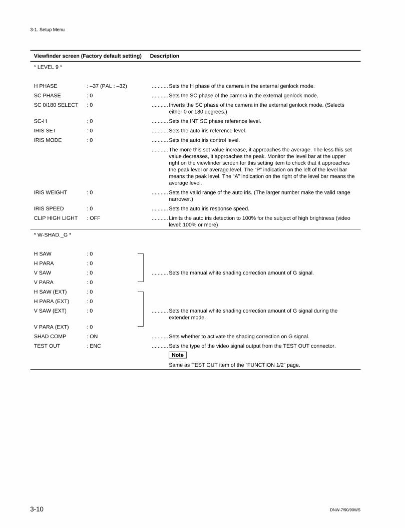
* LEVEL 9 *
H PHASE : –37 (PAL : –32) ........... Sets the H phase of the camera in the external genlock mode.
SC PHASE : 0 ........... Sets the SC phase of the camera in the external genlock mode.
SC 0/180 SELECT : 0 ........... Inverts the SC phase of the camera in the external genlock mode. (Selectseither 0 or 180 degrees.)
SC-H : 0 ........... Sets the INT SC phase reference level.
IRIS SET : 0 ........... Sets the auto iris reference level.
IRIS MODE : 0 ........... Sets the auto iris control level.
........... The more this set value increase, it approaches the average. The less this setvalue decreases, it approaches the peak. Monitor the level bar at the upperright on the viewfinder screen for this setting item to check that it approachesthe peak level or average level. The “P” indication on the left of the level barmeans the peak level. The “A” indication on the right of the level bar means theaverage level.
IRIS WEIGHT : 0 ........... Sets the valid range of the auto iris. (The larger number make the valid rangenarrower.)
IRIS SPEED : 0 ........... Sets the auto iris response speed.
CLIP HIGH LIGHT : OFF ........... Limits the auto iris detection to 100% for the subject of high brightness (videolevel: 100% or more)
* W-SHAD._G *
H SAW : 0
H PARA : 0
V SAW : 0 ........... Sets the manual white shading correction amount of G signal.
V PARA : 0
H SAW (EXT) : 0
H PARA (EXT) : 0
V SAW (EXT) : 0 ........... Sets the manual white shading correction amount of G signal during theextender mode.
V PARA (EXT) : 0
SHAD COMP : ON ........... Sets whether to activate the shading correction on G signal.
TEST OUT : ENC ........... Sets the type of the video signal output from the TEST OUT connector.
n
Same as TEST OUT item of the “FUNCTION 1/2” page.
3-1. Setup Menu

3-11DNW-7/90/90WS
Viewfinder screen (Factory default setting) Description
* W-SHAD._R *
H SAW : 0
H PARA : 0
V SAW : 0 ........... Sets the manual white shading correction amount of R signal.
V PARA : 0
H SAW (EXT) : 0
H PARA (EXT) : 0
V SAW (EXT) : 0 ........... Sets the manual white shading correction amount of R signal during theextender mode.
V PARA (EXT) : 0
SHAD COMP : ON ........... Sets whether to activate the shading correction on R signal.
TEST OUT : ENC ........... Sets the type of the video signal output from the TEST OUT connector.
n
Same as TEST OUT item of the “FUNCTION 1/2” page.
* W-SHAD._B *
H SAW : 0
H PARA : 0
V SAW : 0 ........... Sets the manual white shading correction amount of B signal.
V PARA : 0
H SAW (EXT) : 0
H PARA (EXT) : 0
V SAW (EXT) : 0 ........... Sets the manual white shading correction amount of B signal during theextender mode.
V PARA (EXT) : 0
SHAD COMP : ON ........... Sets whether to activate the shading correction on B signal.
TEST OUT : ENC ........... Sets the type of the video signal output from the TEST OUT connector.
n
Same as TEST OUT item of the “FUNCTION 1/2” page.
* B-SHAD._G *
H SAW : 0
H PARA : 0
V SAW : 0 ........... Sets the manual black shading correction amount of G signal.
V PARA : 0
SHAD COMP : ON ........... Sets whether to activate the shading correction on G signal.
TEST OUT : ENC ........... Sets the type of the video signal output from the TEST OUT connector.
n
Same as TEST OUT item of the “FUNCTION 1/2” page.
3-1. Setup Menu

3-12 DNW-7/90/90WS
Viewfinder screen (Factory default setting) Description
* B-SHAD._R *
H SAW : 0
H PARA : 0
V SAW : 0 ........... Sets the manual black shading correction amount of R signal.
V PARA : 0
SHAD COMP : ON ........... Sets whether to activate the shading correction on R signal.
TEST OUT : ENC ........... Sets the type of the video signal output from the TEST OUT connector.
n
Same as TEST OUT item of the “FUNCTION 1/2” page.
* B-SHAD._B *
H SAW : 0
H PARA : 0
V SAW : 0 ........... Sets the manual black shading correction amount of B signal.
V PARA : 0
SHAD : ON ........... Sets whether to activate the shading correction on B signal.
TEST OUT : ENC ........... Sets the type of the video signal output from the TEST OUT connector.
n
Same as TEST OUT item of the “FUNCTION 1/2” page.
* DCC ADJ. *
D RANGE : 6 ........... Sets the dynamic range during dynamic contrast control.
(0 : approximately 300 %, 6 : approximately 600 %)
POINT : 0 ........... Sets the minimum knee point during dynamic contrast control.
GAIN : 0 ........... Sets the knee slope value during dynamic contrast control.
3-1. Setup Menu

3-13DNW-7/90/90WS
Viewfinder screen (Factory default setting) Description
* OPERATION MODE 1 *
R-G/B-G SEL. : OFF ........... Sets whether to add the R-G and B-G signals to the TEST OUT setting of thesetup menu.
GAMMA TABLE : A (PAL : B) ........... Selects the characteristics of the gamma correction.
More distinct black gradation is obtained when this item is set to B.
Normally setting to A.
A : Sony standard gamma curve
B : High gain gamma curve
LOW LIGHT : OFF ........... Sets the starting level of the LOW LIGHT display on viewfinder.
OFF : No display
1 : Approx. 10 %
2 : Approx. 15 %
3 : Approx. 20 %
BARS SELECT : 1 ........... Sets the type of built-in color bars signal
1 : SMPTE color bars
2 : EBU color bars (PAL)/Full color bars (NTSC)
3 : SNG color bars
WHITE B : AWB ........... Sets the function of white balance (B-CH)
AWB : Auto white balance
ATW : Auto tracing white balance
BATT WARNING : 10% ........... Sets the blinking (alarm) starting level of the remaining amount of battery inANTON BAUER Inc., battery.
10% : Starts blinking when the remaining amount of battery voltage reachesabout 0.67 V.
20% : Starts showing the 20% display when the remaining amount of batteryvoltage reaches about 1.33 V, and starts blinking at about 1.0 V.
WIDE AWB : ON ........... Widens the adjustment range of auto white balance.
ZEBRA : OFF ........... Sets this item when a VF without the zebra switch is used.
A zebra pattern is forcibly displayed on the viewfinder screen regardless of theVF zebra switch setting when this item is set to ON.
* OPERATION MODE 2 *
TIME CODE DISP : OFF ........... Sets whether to output the time code to the TEST OUT connector and viewfind-er screen.
VF : Outputs the time code to the viewfinder only.
TEST : Outputs the time code to the TEST OUT connector only.
BOTH : Outputs the time code to the viewfinder and TEST OUT connector.
OFF : Outputs no time code.
* SG ADJ. *
H BLKG WIDTH : 0 ........... Sets the H blanking width.
V BLKG : 20 H ........... Selects the V blanking width. (19 H, 20 H, or 21 H)
(For NTSC only)
REC TALLY : UPPER ........... Selects which LED is made to be lit when REC tally signal is input.
UPPER : Only the upper-middle LED
BOTH : The upper-middle and lower-middle LEDs
3-1. Setup Menu
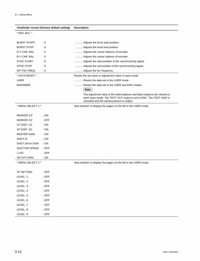
3-14 DNW-7/90/90WS
Viewfinder screen (Factory default setting) Description
* ENC ADJ. *
BURST START : 0 ........... Adjusts the burst start position.
BURST STOP : 0 ........... Adjusts the burst end position.
R-Y CAR. BAL. : 0 ........... Adjusts the carrier balance of encoder.
B-Y CAR. BAL. : 0 ........... Adjusts the carrier balance of encoder.
SYNC START : 0 ........... Adjusts the start position of the synchronizing signal.
SYNC STOP : 0 ........... Adjusts the end position of the synchronizing signal.
INT FSC FREQ. : 0 ........... Adjusts the fsc frequency.
* DATA RESET * Resets the set value or adjustment value in each mode.
USER ........... Resets the data set in the USER mode.
ENGINEER ........... Resets the data set in the USER and ENG modes.
n
The adjustment data of the white balance and black balance are cleared ineach reset mode. The TEST OUT output is set to ENC. The TEST SAW iscanceled and the camera picture is output.
* MENU SELECT 1 * Sets whether to display the pages on the left in the USER mode.
MARKER 1/2 : ON
MARKER 2/2 : OFF
VF DISP. 1/2 : ON
VF DISP. 2/2 : ON
MASTER GAIN : ON
SHOT ID : ON
SHOT DATA DISP. : ON
SHUTTER SPEED : OFF
! LED : OFF
SETUP CARD : ON
* MENU SELECT 2 * Sets whether to display the pages on the left in the USER mode.
VF SETTING : OFF
LEVEL -1 : OFF
LEVEL -2 : OFF
LEVEL -3 : OFF
LEVEL -4 : OFF
LEVEL -5 : OFF
LEVEL -6 : OFF
LEVEL -7 : OFF
LEVEL -8 : OFF
LEVEL -9 : OFF
3-1. Setup Menu

3-15DNW-7/90/90WS
Viewfinder screen (Factory default setting) Description
* MENU SELECT 3 * Sets whether to display the pages on the left in the USER mode.
W-SHAD._G : OFF
W-SHAD._R : OFF
W-SHAD._B : OFF
B-SHAD._G : OFF
B-SHAD._R : OFF
B-SHAD._B : OFF
FUNCTION 1/2 : OFF
FUNCTION 2/2 : OFF
WIDE SCREEN : ON (DNW-9WS/9WSP/90WS/90WSP only)
* MENU SELECT 4 * Sets whether to display the pages on the left in the USER mode.
DCC ADJUSTMENT : OFF
OPERATION MODE 1: OFF
OPERATION MODE 2: ON
SG ADJUSTMENT : OFF
ENC ADJUSTMENT : OFF
DATA RESET : OFF
* MEASUREMENT MODE * Automatically makes various settings required to measure the following specifications(when this item is set to ON).
S/N : OFF ........... S/N DETAIL : OFF
APERTURE : OFF
CHROMA : OFF
GAMMA : OFF
MATRIX : OFF
FLARE : OFF
MODULATION : OFF ........... MODULATION (modulation degree) DETAIL : OFF
APERTURE : OFF
GAMMA : OFF
MATRIX : OFF
FLARE : OFF
RESOLUTION : OFF ........... RESOLUTION MATRIX : OFF
SENSITIVITY : OFF ........... SENSITIVITY KNEE : OFF
WHITE CLIP : OFF
REGISTRATION : OFF ........... REGISTRATION DETAIL : OFF
APERTURE : OFF
MASTER BLACK : 0 ........... Adjusts master black.
TEST OUT : ENC ........... Sets the type of the video signal output from the TEST OUT connector.
n
Same as TEST OUT item of the FUNCTION 1/2 page.
* WHT PRESET * Used for the manual adjustment when the white balance memory is preset.
R WHT PRESET : 0 ........... Sets the FILTER selector to 1 (3200 K), shoots the light source (pattern box) ofB WHT PRESET : 0 the required color temperature, and sets the levels in channels R and B so that
the white balance is adjusted.
n
Check the WHITE BAL switch on the inside panel to PRST.
3-1. Setup Menu

3-16 DNW-7/90/90WS
Setup menu check sheet
<CANCEL> Yes or No is displayed to indicate whether the value set by the UP/DOWN button can be canceled usingthe CANCEL/PRST switch.
<PRESET> Yes or No is displayed to indicate whether the factory default value can be returned using the CAN-CEL/PRST switch.
<SETUP C> Yes or No is displayed to indicate whether data can be written in the setup card.<RM-P9> M, P, or No is displayed to indicate whether this item can be operated when remote control unit RM-P9
is connected.M (MENU) : Can be operated at the bottom of the RM-P9.P (PANEL) : Can be operated in the front of the RM-P9.No : Cannot be operated by the RM-P9.
<F-SET> Sets the factory default value.<C-SET> Write the setting state of the customer.
3-1. Setup Menu

3-17DNW-7/90/90WS
PAGE ITEM CANCEL PRESET SETUP C RM-P9 F-SET C-SET
MARKER 1/2 SAFETY ZONE NO NO YES M ON
SAFETY AREA NO NO YES M 90%
CENTER NO NO YES M ON
CENTER H YES YES YES M
CENTER V YES YES YES M
MARKER 2/2 BOX CURSOR NO NO YES M OFF
BOX WIDTH YES YES YES M
BOX HEIGHT YES YES YES M
BOX H YES YES YES M
BOX V YES YES YES M
VF DISPLAY 1/2 DISP MODE NO NO YES M 3
EXTENDER NO NO YES M ON
ZOOM NO NO YES M ON
VF DISPLAY 2/2 FILTER NO NO YES M ON
WHITE NO NO YES M ON
GAIN NO NO YES M ON
SHUTTER NO NO YES M ON
TAPE NO NO YES M ON
AUDIO NO NO YES M ON
IRIS NO NO YES M ON
MASTER GAIN LOW NO YES YES M 0dB
MID NO YES YES M 9dB
HIGH NO YES YES M 18dB
TURBO NO YES YES M 36dB
SHOT ID ID1 YES YES YES M (Blank)
ID2 YES YES NO M (Blank)
ID3 YES YES NO M (Blank)
ID4 YES YES NO M (Blank)
SHOT DATA DISP. DATE NO NO YES M OFF
TIME NO NO YES M OFF
MODEL NAME NO NO YES M OFF
SERIAL NO. NO NO YES M OFF
CASSTTE NO. NO NO YES M OFF
SHOT NO. NO NO YES M OFF
ID SELECT NO NO YES M OFF
SHUTTER SPEED EVS NO NO YES P ON
CLS NO NO YES P ON
1/100 (1/60) NO NO YES P ON
1/125 NO NO YES P ON
1/250 NO NO YES P ON
1/500 NO NO YES P ON
1/1000 NO NO YES P ON
1/2000 NO NO YES P ON
3-1. Setup Menu

3-18 DNW-7/90/90WS
PAGE ITEM CANCEL PRESET SETUP C RM-P9 F-SET C-SET
! LED MASTER GAIN NO NO YES M ON
SHUTTER ON NO NO YES M ON
WHITE PRESET NO NO YES M OFF
ATW RUN NO NO YES M OFF
EXTENDER ON NO NO YES M ON
FILTER 2,3,4 NO NO YES M OFF
A. IRIS OVERRIDE NO NO YES M OFF
SETUP CARD READ (→ CAM) — — — M
WRITE (→ CARD) — — — M
ID EDIT — — — M
WRITE PROTECT — — — M OFF
FUNCTION 1/2 TEST OUT NO YES NO M ENC
DETAIL NO NO YES P ON
APERTURE NO NO YES M ON
SKIN TONE DTL NO NO YES M OFF
MATRIX NO NO YES M OFF (PAL:ON)
GAMMA NO NO YES M ON
CHROMA NO NO YES M ON
TEST SAW NO NO YES P OFF
CROSS COLOR FLT NO NO YES M OFF (NTSC only)
FUNCTION 2/2 GENLOCK NO NO YES M ON
CAM RET. NO NO YES M OFF
FILTER INH. NO NO YES NO OFF
FIELD/FRAME NO NO YES M FLD
A. IRIS OVERRIDE NO NO YES P OFF
DYNALATITUDE NO NO YES M OFF
WIDE SCREEN 16:9/4:3 MODE NO NO YES M 16:9
VF ASPECT NO NO YES M AUTO
BOX/4:3 LIMITS NO NO YES M BOX
"16:9" BARS ID NO NO YES M OFF
"16:9" VF ID NO NO YES M OFF
VF SETTING ZEBRA1 DETECT YES YES YES M 0
ZEBRA1 APT. YES YES YES M 0
ZEBRA2 DETECT YES YES YES M 0
ZEBRA SELECT NO NO YES M 1
VF VDTL LEVEL NO NO YES M 0
3-1. Setup Menu

3-19DNW-7/90/90WS
PAGE ITEM CANCEL PRESET SETUP C RM-P9 F-SET C-SET
LEVEL 1 DETAIL LEVEL YES YES YES P 0
V DTL LEVEL YES YES YES M 0
APERTURE LEVEL YES YES YES M 0
KNEE APERTURE YES YES YES M 0
V DTL BLK CLIP YES YES YES M 0
DTL BLK CLIP YES YES YES M 0
LEVEL DEPEND YES YES YES M MIN
CRISPENING NO NO YES M 4
DTL FREQ NO NO YES M 4
LEVEL 2 SUPPRESS LEVEL YES YES YES M MIN
X YES YES YES M 0
Y YES YES YES M 0
dX YES YES YES M 0
dY YES YES YES M 0
SKIN TONE DTL NO NO YES M OFF
SKIN TONE IND. NO NO NO M OFF
SKIN TONE DET. NO NO NO M OFF
LEVEL 3 MASTER BLACK YES YES YES P MIN
MASTER GAMMA YES YES YES P 0
KNEE POINT 1 YES YES YES P 0
KNEE SLOPE 1 YES YES YES M 0
KNEE POINT 2 YES YES YES NO 0
KNEE SLOPE 2 YES YES YES NO 0
KNEE SELECT NO NO YES NO 1
WHITE CLIP NO NO YES M ON
WHT CLIP LEV. YES YES YES M MIN
LEVEL 4 BURST LEVEL YES YES YES M 0
BURST PHASE YES YES YES M 0 (PAL only)
R-Y NO NO NO M ON
B-Y NO NO NO M ON
R-Y LEVEL YES YES YES M 0 *1
B-Y LEVEL YES YES YES M 0 *1
R-Y LEVEL YES YES YES M 0 *2
B-Y LEVEL YES YES YES M 0 *2
LEVEL 5 RGB LEVEL YES YES YES M 0 *1
RGB SYNC LEV. YES YES YES M 0
RGB SETUP LEV. YES YES YES M 0
ENC Y LEVEL YES YES YES M 0 *1
ENC SYNC LEV. YES YES YES M 0
ENC SETUP LEV. YES YES YES M 0
RGB LEVEL YES YES YES M 0 *2
ENC Y LEVEL YES YES YES M 0 *2
*1:DNW-7, DNW-9WS/9WSP/90WS/90WSP (4:3 mode) only*2:DNW-90, DNW-9WS/9WSP/90WS/90WSP (16:9 mode) only
3-1. Setup Menu

3-20 DNW-7/90/90WS
PAGE ITEM CANCEL PRESET SETUP C RM-P9 F-SET C-SET
LEVEL 6 R BLACK YES YES YES P 0
G BLACK YES YES YES M 0
B BLACK YES YES YES P 0
R GAMMA YES YES YES M 0
G GAMMA YES YES YES M 0
B GAMMA YES YES YES M 0
BLACK STRETCH NO NO YES M 2
TEST OUT NO YES NO M ENC
LEVEL 7 R FLARE YES YES YES M 0
G FLARE YES YES YES M 0
B FLARE YES YES YES M 0
FLARE NO NO YES M ON
TEST OUT NO NO NO M ENC
LEVEL 8 MATRIX TABLE NO NO YES M A
R-G YES YES YES M 0
R-B YES YES YES M 0
G-R YES YES YES M 0
G-B YES YES YES M 0
B-R YES YES YES M 0
B-G YES YES YES M 0
MATRIX YES YES YES M OFF (PAL:ON)
LEVEL 9 H PHASE YES YES YES M 0
SC PHASE YES YES YES M 0
SC 0/180 SELECT NO NO YES M 0
SC-H YES YES YES M 0
IRIS SET YES YES YES P 0
IRIS MODE YES YES YES M 0
IRIS WEIGHT NO NO YES M 2
IRIS SPEED NO NO YES M 0
CLIP HIGH LIGHT NO NO YES M OFF
W-SHAD._G H SAW YES YES YES M 0
H PARA YES YES YES M 0
V SAW YES YES YES M 0
V PARA YES YES YES M 0
H SAW (EXT) YES YES YES M 0
H PARA (EXT) YES YES YES M 0
V SAW (EXT) YES YES YES M 0
V PARA (EXT) YES YES YES M 0
SHAD COMP. NO NO YES M ON
TEST OUT NO YES NO M ENC
3-1. Setup Menu

3-21DNW-7/90/90WS
PAGE ITEM CANCEL PRESET SETUP C RM-P9 F-SET C-SET
W-SHAD._R H SAW YES YES YES M 0
H PARA YES YES YES M 0
V SAW YES YES YES M 0
V PARA YES YES YES M 0
H SAW (EXT) YES YES YES M 0
H PARA (EXT) YES YES YES M 0
V SAW (EXT) YES YES YES M 0
V PARA (EXT) YES YES YES M 0
SHAD COMP. NO NO YES M ON
TEST OUT NO YES NO M ENC
W-SHAD._B H SAW YES YES YES M 0
H PARA YES YES YES M 0
V SAW YES YES YES M 0
V PARA YES YES YES M 0
H SAW (EXT) YES YES YES M 0
H PARA (EXT) YES YES YES M 0
V SAW (EXT) YES YES YES M 0
V PARA (EXT) YES YES YES M 0
SHAD COMP. NO NO YES M ON
TEST OUT NO YES NO M ENC
B-SHAD._G H SAW YES YES YES M 0
H PARA YES YES YES M 0
V SAW YES YES YES M 0
V PARA YES YES YES M 0
SHAD COMP. NO NO YES M ON
TEST OUT NO YES NO M ENC
B-SHAD._R H SAW YES YES YES M 0
H PARA YES YES YES M 0
V SAW YES YES YES M 0
V PARA YES YES YES M 0
SHAD COMP. NO NO YES M ON
TEST OUT NO YES NO M ENC
B-SHAD._B H SAW YES YES YES M 0
H PARA YES YES YES M 0
V SAW YES YES YES M 0
V PARA YES YES YES M 0
SHAD COMP. NO NO YES M ON
TEST OUT NO YES NO M ENC
DCC ADJ. D RANGE NO NO YES M 6
POINT YES YES YES P 0
GAIN YES YES YES M 0
3-1. Setup Menu

3-22 DNW-7/90/90WS
PAGE ITEM CANCEL PRESET SETUP C RM-P9 F-SET C-SET
OPERATION MODE 1 R-G/B-G SEL NO NO YES M OFF
GAMMA TABLE NO NO YES M A (PAL:B)
LOW LIGHT NO NO YES M OFF
BARS SELECT NO NO YES M 1 (PAL:2)
WHITE B NO NO YES NO AWB
BATT WARNING NO NO YES M 10%
WIDE AWB NO NO YES M ON
ZEBRA NO NO YES M OFF
REC TALLY NO NO YES M UPPER
OPERATION MODE 2 TIME CODE DISP. NO NO YES M OFF
SG ADJ. H BLKG WIDTH YES YES YES M 0
V BLKG NO NO YES M 20H (NTSC only)
ENC ADJ. BURST START YES YES YES M 0
BURST STOP YES YES YES M 0
R-Y CAR. BAL. YES YES YES M 0
B-Y CAR. BAL. YES YES YES M 0
SYNC START YES YES YES M 0
SYNC STOP YES YES YES M 0
INT FSC FREQ. YES YES YES M 0
DATA RESET USER — — — NO
ENGINEER — — — NO
MENU SELECT 1 MARKER 1/2 NO NO YES M ON
MARKER 2/2 NO NO YES M OFF
VF DISP. 1/2 NO NO YES M ON
VF DISP. 2/2 NO NO YES M ON
MASTER GAIN NO NO YES M ON
SHOT ID NO NO YES M ON
SHOT DATA DISP. NO NO YES M ON
SHUTTER SPEED NO NO YES M OFF
! LED NO NO YES M OFF
SETUP CARD NO NO YES M ON
MENU SELECT 2 VF SETTING NO NO YES M OFF
LEVEL 1 NO NO YES M OFF
LEVEL 2 NO NO YES M OFF
LEVEL 3 NO NO YES M OFF
LEVEL 4 NO NO YES M OFF
LEVEL 5 NO NO YES M OFF
LEVEL 6 NO NO YES M OFF
LEVEL 7 NO NO YES M OFF
LEVEL 8 NO NO YES M OFF
LEVEL 9 NO NO YES M OFF
3-1. Setup Menu

3-23DNW-7/90/90WS
PAGE ITEM CANCEL PRESET SETUP C RM-P9 F-SET C-SET
MENU SELECT 3 W-SHAD._ G NO NO YES M OFF
W-SHAD._ R NO NO YES M OFF
W-SHAD._ B NO NO YES M OFF
W-SHAD._ G NO NO YES M OFF
W-SHAD._ R NO NO YES M OFF
W-SHAD._ B NO NO YES M OFF
FUNCTION 1/2 NO NO YES M OFF
FUNCTION 2/2 NO NO YES M OFF
WIDE SCREEN NO NO YES M ON (DNW-9WS/9WSP/90WS/90WSP only)
MENU SELECT 4 DCC ADJ. NO NO YES M OFF
OPERATION MODE 1 NO NO YES M OFF
OPERATION MODE 2 NO NO YES M ON
SG ADJ. NO NO YES M OFF
ENC ADJ. NO NO YES M OFF
DATA RESET NO NO YES M OFF
MEASUREMENT MODE S/N — — — NO OFF
MODULATION — — — NO OFF
RESOLUTION — — — NO OFF
SENSITIVITY — — — NO OFF
REGISTRATION — — — NO OFF
MASTER BLACK — — — NO 0
TEST OUT NO YES NO M ENC
WHT PRESET R WHT PRESET YES YES YES NO 0
B WHT PRESET YES YES YES NO 0
3-1. Setup Menu

3-24 DNW-7/90/90WS
3-2. DIAG Menu
The DIAG menu is used for the maintenance menu setting and troubleshooting of the DNV-5.
m. Use the DIAG menu in the state in which the tape transport stopped.. Do not execute the DIAG menu when remote control RM-P9 is connected. The self-diagnosis function
and remote control function are not normally activated when the self-diagnosis is executed.
Operation1. DIAG menu activation
Push the DIAG switch on the inside panel with the tip of a clip so as to display the DIAG menu onthe LCD display.
2. PAGE selectionPress the ADVANCE button and select the PAGE.
To increment the menu number, press the ADVANCE button.To decrement the menu number, press the ADVANCE and HOLD buttons simultaneously.
After selection, Press the SHIFT button.Select the PAGE repeatedly until the desired ITEM is found.
3. ITEM selectionPress the ADVANCE button and select the ITEM.After selection, press the SHIFT button.
4. ITEM settingPress the ADVANCE button to change the set value.After change, press the SHIFT button.
5. DIAG menu terminationPress the DIAG switch.
3-2. DIAG Memu

3-25DNW-7/90/90WS
1:REC VIDEO DATA 1
2:REC VIDEO DATA 2
3:REC VIDEO DATA 3 (NTSC only)
0:HOURS METER
LCD
XX
1:DRUM RUNNING
2:TAPE RUNNING
3:OPERATION
4:THREADING
5:DRUM RUN-2
6:TAPE RUN-2
7:OPERATION-2
8:THREADING-2
1:TIME SET
2:DATE SET
3:BAT BEF END
4:BAT END
5:VITC LINE
6:VTR MODE SELECT 1:VTR MODE SELECT-1 V/AU OUT
AU OUT(F/R)
AU OUT CH
AU REC CH3/4
2:VTR MODE SELECT-2 AU REC EMPH
AU SG(1kHz)
AU SG LEVEL
AU ADAPTER
3:VTR MODE SELECT-3 TC OUT
EXT-LK UBIT
EXT-LK DF/NDF
WATCH AUTO ADJ
UB WATCH MIX
4:VTR MODE SELECT-4 REC TALLY BLINK
LIGHT OFF NEAR END
5:VTR MODE SELECT-5 REC START/STOP TONE
AUTO SHOT NO RESET
SHOT TIME DISP
6:VTR MODE SELECT-6 LTC UBIT
LTC UBIT MARKER
REC START MARKER
SHOT MARKER1
SHOT MARKER2
7:VTR MODE SELECT-7 VITC UBIT
UB DATA
7:WATCH REVISION
8:LCD/LED CHECK
9:SLACK DATA
D:PB EQ DATA 1:PB EQ A-CH DATA
2:PB EQ A-CH DATA
3:PB EQ B-CH DATA
4:PB EQ B-CH DATA
5:PB EQ C-CH DATA
6:PB EQ C-CH DATA
7:PB EQ D-CH DATA
8:PB EQ D-CH DATA
E:REC CURRENT DATA 1:REC CURRENT DATA 1
2:REC CURRENT DATA 2
F:PB VIDEO DATA 1:PB VIDEO DATA
G:REC VIDEO DATA
1:SLACK DATA 1
2:SLACK DATA 2
3:SLACK DATA 3
4:SLACK DATA 4
3-2. DIAG Memu

3-26 DNW-7/90/90WS
LCD Display (factory setting) Description
DIAG 0
HOURS METER The contents below are displayed. (For more details, refer to 6-3-1, “Hours Meter”.)
1. DRUM RUNNING ........... Total drum rotating hours
2. TAPE RUNNING ........... Total tape running hours
3. OPERATION ........... Total power-on time
4. THREADING ........... Total number of threading
5. DRUM RUN-2 ........... Drum rotating hour (Customer-resetable)
6. TAPE RUN-2 ........... Tape running hour (Customer-resetable)
7. OPERATION-2 ........... Power-on time (Customer-resetable)
8. THREADING-2 ........... The number of threading (Customer-resetable)
DIAG 1
TIME Internal timer setting.
1. Sets the hour.
2. Sets the minute.
3. Sets the second.
DIAG 2
DATE Internal timer date setting.
1. Sets the month (for NTSC) /day (for PAL).
2. Sets the day (for NTSC) /month (for PAL).
3. Sets the year.
DIAG 3
BATTERY VOLTAGE Displays and sets the battery before end voltage.(For the setting, refer to the Operation Manual.)
BEFORE END Battery before end voltage setting
11.0 to 13.0 V (in units of 0.1 V)“0” is displayed on the LCD when the setting is OK.“E” is displayed on the LCD when the setting is NG.
DIAG 4
BATTERY VOLTAGE Displays and sets the battery end voltage. (For the setting, refer to the Operation Manual.)
END Battery end voltage setting10.5 to 11.5 V (in units of 0.1 V)“0” is displayed on the LCD when the setting is OK.“E” is displayed on the LCD when the setting is NG.
DIAG 5
VITC INSERT LINE Displays and sets the VITC insertion line.
12 to 19 lines (For NTSC)
9 to 22 lines (For PAL)
3 11.3
4 11.0
5 1618NEXT LINEFIRST LINE
0X XXXX
1 XXXXXX
1 2 3
2 XXXXXX
1 2 3
3-2. DIAG Memu

3-27DNW-7/90/90WS
LCD Display (factory setting) Description
DIAG 6-1
VTR MODE SEL-1
1. V/AU OUT : Sets the video and audio output.
0 : Outputs the PB/EE signal.1 : Outputs the EE signal.
2. AU OUT (F/R) : Sets the audio output during FF/REW.(Valid when V/AU OUT is set to 0.)
0 : Outputs the EE signal.1 : Outputs no signal.
3. AU OUT CH : Sets the audio output channel.
0 : CH1/21 : CH3/4
4. AU REC CH3/4 : Selects the source during recording in CH3/4.
(Valid when no camera adapter (CA-701) is connected or when AU ADAPTERENABLE is disabled.)
0 : Front MIC input (CH3) and wireless receiver input (CH4).1 : Records the same signal as in CH1/2.2 : Not use CH3/4.
DIAG 6-2
VTR MODE SEL-2
1. AU REC EMPH : Sets the audio emphasis (during recording) to ON or OFF.
0 : OFF1 : ON
2. AU SG (1 kHz) : Sets whether to generate a 1 kHz test signal when a color-bar signal isgenerated from the internal signal generator.
0 : Not generates.1 : Generates when the CH1 AUDIO SELECT switch on the inside panel is set to
AUTO.2 : Generates.
3. AU SG LEVEL : Sets the level of a 1 kHz test signal.
0 : _20 dBu (600 Z)1 : _18 dBu (600 Z)2 : _16 dBu (600 Z)
4. AU ADAPTER : Sets whether to connect the camera adapter (CA-701).
0 : Connects.1 : Not connect.
62 0000
1 2 3 4
61 0000
1 2 3 4
3-2. DIAG Memu

3-28 DNW-7/90/90WS
LCD Display (factory setting) Description
DIAG 6-3
VTR MODE SEL-3
1. TC OUT : Sets the time code output.
0 : Outputs PB/TCG.1 : Outputs TCG.
2. EXT-LK UBIT : Sets the LTC UB set value when the time code is locked externally.
0 : Internally set value1 : External LTC value
3. EXT-LK DF/NDF : Sets the DF/NDF (NTSC only).
0 : Conforms to the DF/NDF switch setting on the inside panel.1 : Conforms to the external LTC setting.
4. WATCH AUTO ADJ : Sets the internal timer automatic time correction (according to theuser’s bit of the unit connected to TC OUT).
0 : Corrects.1 : Not correct.
5. UB WATCH MIX : Sets whether to output the time of an internal timer to the LTC UB.
0 : Not output.1 : Outputs.
DIAG 6-4
VTR MODE SEL-4
1. REC TALLY BLINK : Sets whether the TALLY lamp blinks during battery before endand tape before end.
0 : Blinks.1 : Lights.
2. LIGHT OFF NEAR END : Sets whether to turn off the light during battery before end.
0 : Turns off forcibly.1 : Not turn off.
DIAG 6-5
VTR MODE SEL-5
1. REC START/STOP TONE : Sets whether to output a sound when the REC START/STOP button is pressed.
0 : Outputs no sound.1 : Outputs a sound.
2. SHOT NO. RESET : Sets whether to reset the shot number automatically during tape-threading.
0 : Resets automatically.1 : Not reset.
3. SHOT TIME DISP : Sets the format of the time displayed on the LCD.
0 : Month Day : Hour Minute1 : Day Month : Hour Minute2 : Day : Hour Minute Second
63 00000
1 2 3 4 5
65 000
1 2 3
64 00
1 2
3-2. DIAG Memu

3-29DNW-7/90/90WS
LCD Display (factory setting) Description
DIAG 6-6
VTR MODE SEL-6
1. LTC UBIT : Sets the data recorded in the user bits of LTC.
0 : Fixed data (Conventional-type user bits)1 : Time of internal timer (in real time)2 : Shot data
2. LTC UB-MARKER : Sets whether to write the mark below in the user bits of LTC.REC start markShot mark 1Shot mark 2
0 : Conform to the menu setting below.1 : Writes all marks.2 : Writes nothing.
3. REC START MARKER(Valid when the LTC UB-maker is set to SW.)
0 : Writes.1 : Not write.
4. SHOT MARKER 1(Valid when the LTC UB-marker is set to SW.)
0 : Writes.1 : Not write.
5. SHOT MARKER 2(Valid when the LTC UB-marker is set to SW.)
0 : Writes.1 : Not write.
DIAG 6-7
VTR MODE SEL-7
1. VITC UBIT : Sets the data recorded in the user bits of VITC.
0 : Fixed data (Conventional-type user bits)1 : Time of internal timer (in real time)2 : Shot data
2. SHOT DATA : Sets the data length of the VITC shot data.
0 : Record data of date, time, model ID, serial No., cassette No., shot No.1 : Record data of date, time, model ID, serial No., cassette No., shot No.,
shot ID 1 to 4.
66 00000
1 2 3 4 5
67 00
1 2
3-2. DIAG Memu

3-30 DNW-7/90/90WS
LCD Display (factory setting) Description
DIAG 7
WATCH REVISION Sets the corrected value of an internal timer (the number of frames a day).
DIAG 8
LCD/LAMP CHECK Sets the LCD light check.
All the lamps are turned on or off every time the SHIFT button is pressed.
DIAG 9
1. SLACK DATA 1 ........................ Slack trouble code 1 (latest)Slack state code 1 (latest)
2. SLACK DATA 2 ........................ Slack trouble code 2Slack state code 2
3. SLACK DATA 3 ........................ Slack trouble code 3Slack state code 3
4. SLACK DATA 4 ........................ Slack trouble code 4Slack state code 4
. Contents of slack trouble code
10 : Abnormal drum drive voltage11 : No drum FG output12 : No drum PG output20 : Abnormal capstan drive voltage21 : No capstan FG-A output22 : No capstan FG-B output23 : Abnormal forward/reverse rotation of capstan24 : Abnormal capstan speed (high-speed)32 : No S reel FG output42 : No T reel FG output61 : Time over the forward rotation time of function cam62 : Time over the reverse rotation time of function cam63 : Time over the tape top sensor64 : Time over the full top sensor65 : Time over the end sensor time70 : Servo NVRAM checksum error71 : Communication error between servo CPUs
. Contents of slack state code
00 : Power-on initialization1x : No cassette and standby state2x : Record3x : Stop4x : FF/REW5x : Playback6x : REC PAUSE7x : REC REVIEW8x : Threading/unthreading
8
9X XXXXSTATE CODETROUBLE CODE
7 XXX
3-2. DIAG Memu

3-31DNW-7/90/90WS
LCD Display (factory setting) Description
DIAG D-1
PG EQ ADJ DATA-1 Displays the equalizer adjustment data (A-CH).
1. A-CH FREQ
2. A-CH PHASE
3. A-CH GAIN
DIAG D-2
PG EQ ADJ DATA-2 Displays the equalizer adjustment data (A-CH).
1. A-CH ENV
2. A-CH PLL
DIAG D-3
PG EQ ADJ DATA-3 Displays the equalizer adjustment data (B-CH).
1. B-CH FREQ
2. B-CH PHASE
3. B-CH GAIN
DIAG D-4
PG EQ ADJ DATA-4 Displays the equalizer adjustment data (B-CH).
1. B-CH ENV
2. B-CH PLL
DIAG D-5
PG EQ ADJ DATA-5 Displays the equalizer adjustment data (C-CH).
1. C-CH FREQ
2. C-CH PHASE
3. C-CH GAIN
DIAG D-6
PG EQ ADJ DATA-6 Displays the equalizer adjustment data (C-CH).
1. C-CH ENV
2. C-CH PLL
d1XXXXXX
1 2 3
d2 XXXX
1 2
d3XXXXXX
1 2 3
d4 XXXX
1 2
d5XXXXXX
1 2 3
d6 XXXX
1 2
3-2. DIAG Memu

3-32 DNW-7/90/90WS
LCD Display (factory setting) Description
DIAG D-7
PG EQ ADJ DATA-7 Displays the equalizer adjustment data (D-CH).
1. D-CH FREQ
2. D-CH PHASE
3. D-CH GAIN
DIAG D-8
PG EQ ADJ DATA-8 Displays the equalizer adjustment data (D-CH).
1. D-CH ENV
2. D-CH PLL
DIAG E-1
REC CURRENT DATA-1 Displays the REC current adjustment data.
1. A-CH
2. B-CH
DIAG E-2
REC CURRENT DATA-2 Displays the REC current adjustment data.
1. C-CH
2. D-CH
DIAG F
PB VIDEO ADJ DATA Displays the PB video adjustment data.
1. VIDEO LEVEL
2. INT BURST FRQ
DIAG G-1
REC VIDEO ADJ DATA-1 Displays the REC video adjustment data.
1. Not used
2. R-Y DELAY
3. B-Y DELAY
DIAG G-2
REC VIDEO ADJ DATA-1 Displays the REC video adjustment data.
1. Y LEVEL
2. R-Y LEVEL
3. B-Y LEVEL
E1 XXXX
1 2
E2 XXXX
1 2
F XXXX
1 2
G1XXXXXX
1 2 3
G2XXXXXX
1 2 3
d7XXXXXX
1 2 3
d8 XXXX
1 2
3-2. DIAG Memu

4-1DNW-7/90/90WS
Section 4Block Diagram and Circuit Description
Circuit Description
(1) Camera process system(DCP-31/1 and ES-11 boards)
. DCP-31/1 boardThe DCP-31/1 board consists of the following blocks:(1) Receiver of R/G/B signals from the CCD block, A/D
converters for R/G/B signals, Digital processor toconvert to the digital component signals, and D/Aconverter so as to output the Y/R-Y/B-Y/VF signalsto the ES-11 board.
(2) Driver block which adds the character data to thecomposite signal supplied from the ES-11 board,and outputs the added signal.
(3) Rate converter(4) Signal processor for viewfinder
The analog R/G/B signals which are input from the CCDblock are passed through the respective pre-filters havingthe corresponding sampling frequencies (WIDE/NOR-MAL), then are converted by the A/D converter to the10-bit digital R/G/B signals of 14 MHz (NORMAL) or18 MHz (WIDE) rate respectively.The digital R/G/B signals after A/D conversion are inputto the pre-process IC. This IC detect the average valueand peak value of the video signals detected which arerequired by the AUTO operation system of the camerasuch as auto black balance, auto white balance and autoiris and so on.The pre-process IC outputs the black and white shadingcorrection signals (G BSH, R BSH, B BSH/G WSH, RWSH and B WSH), feed-back clamp control signal (GFB, R FB and B FB) and TEST SAW signal to the CCDblock.
The digital G and R signals output from the pre-processIC are passing through the 1H delay lines to generatesthe V details, and input to the processor IC. But digital Bsignal output from the pre-process IC is input theprocessor IC directly.In the processor IC, the digital R/G/B signals are up-converted to 28 MHz (NORMAL) or 36 MHz (WIDE)signal respectively, the matrix and the detail signals areadded, the flare compensation, pedestal control, gammacorrection, knee correction and white clip are applied,then converted to the digital component signals (Y, R-Yand B-Y).
The processor IC has the function of the output signalswitch circuit which switches between the built-in colorsignal and the main line signal. The processor IC alsohas the Y, R/G/B video outputs circuit for viewfinder.The output signals of the processor IC are D/A convertedand send to the VF or TEST OUT terminal. The view-finder output circuit has the signal selector functionwhich enables monitoring the video signal supplied tothe GENLOCK IN connector or the RET video signalwhen a CCU is connected, using the monitor select IC.
The digital component signal output from the processorIC is passed through the CN-1193 board *1, and input tothe rate converter and D/A converter. The digital compo-nent signal is rate-converted to 27 MHz by rate convert-er, and output to the DVP-1 board. The other digitalcomponent signal is D/A converted, and resultant analogcomponent signals (Y, R-Y, B-Y) are output to ES-11board.
The average value and peak value of the video signalwhich are detected in the pre-process IC are sent to thecamera CPU and the control CPU via I/O expanderthrough the 4-bit LSI data bus.After processing the detected values by the camera CPU,the control data is sent to the processor IC and VA-191/167 board in CCD block through data bus and SAD(CCD) signal.The control CPU performs the various controls of thecamera block in accordance with the commands stored inthe ROM. The control CPU decodes the variable controldata which are detected in pre-process IC, functionswitch command and analog data, and then output thevarious control signals.The control CPU writes the status information and theself-diagnostics information to the character generatorand outputs these data as the character data.Connection with the external equipment such as RM-P9(optional) and VA-DN1 (optional) is made possible bythe transmitter/receiver IC.

4-2 DNW-7/90/90WS
(2) Digital signal system(DVP-1 (1/2) board, DVP-2 board, and drumassembly)
. Signal processing during recordingThe parallel video data supplied from the camera iscompressed to a data rate of approximately 1/10 using anSX encoder after addition of the VITC signal.The compressed video data is input to the ECC encoderwhere an outer ECC is added to the video data and track-interleaved.The serial audio data (A/D DATA 1/2 and 3/4) suppliedfrom the TC-80 board is also input to the ECC encoderwhere an outer ECC is added and the audio data is field-shuffled. The video data and audio data are multiplexedand inner-ECC-encoded by the ECC encoder. The resultant data is then sent to the drum as the four-channel parallel record data.The Betacam SX Camcorder records the video and audiosignals on magnetic tape in a Betacam SX format.The Betacam SX Camcorder uses the four rotary headswhich have an azimuth angle in the opposite direction toeach other, and are paired. Every rotation of the drumrecords the four helical tracks. Every five rotations ofthe drum i.e., the twenty helical tracks record the fourframe data.* The Betacam format of the PAL system records the twoframe data with three rotations, i.e., twelve helical tracks.
. Signal processing during playbackThe four-channel parallel PB data sent from the drum isinner-corrected by the inner ECC decoder.The parallel PB data is then deinterleaved and sent to theouter ECC decoder where the video data is outer-corrected and sent to the SX decoder.The SX decoder perform the bit rate reduction decodingof the playback video data so that the original data rate isrestored.The errors that cannot be corrected by the ECC decoderare sent to the memory where separate error correction isperformed. This data feedback to the camera block.Audio data is outer-corrected, error-corrected, thenconverted of its clock rate using FIFO memory. The audiodata is sent to the audio data processor in the form of two-channel serial audio data (CONFI AU 1/2 and 3/4).The NTSC Betacam SX system is equipped with a five-field sequence generator which controls the five-fieldsequence of audio playback data.The digital data processing in each IC is performedunder communication with the system control CPU.
. ES-11 boardThe ES-11 board consists of the two major circuit: one isthe circuit which generated the composite signal fromthe D/A converted analog component signal suppliedfrom the DCP-31/1 board, and the other circuit which isthe sync generator circuit generating the various syncsignals for comcorder.Almost adjustments are performed by electronic controlusing setup menu.The ES-11 board has the sync separator IC and PLL ICso that the camera block is sync-locked to the externalinput video signal supplied from the GENLOCK INterminal.
*1: In DNW-9WS/9WSP/90WS/90WSP, this circuitoperated as follows:In the 4:3 mode, the digital component signal fromthe processor IC is stretched by down-convertingfrom 18 MHz to 13.5 MHz, then is re-sampled by 18MHz and is output.

4-3DNW-7/90/90WS
(3) Audio system(AXM-14 board (1/2), CNB-1 board (1/2), TC-80board (1/2), RX-26 board, MA-68 board andAIF-8 board)
The audio system of the Betacam SX recorder has theconfiguration of the four input channels and the two outputchannels.The CH-1 and CH-2 have the “AUDIO IN” switcheswhich select their input signals from either the LINE/MICinput (rear input) signals coming from the XLR connectorson the rear panel, or the camera MIC input signal (frontMIC input: CH-3) coming from the camera, or the wirelessaudio input signal (CH-4) coming from the slot-in wirelessreceiver, to be recorded on tape.The selected input signal is A/D converted and sent to theaudio data processor as the AU A/D data (1/2 and 3/4).The output signal from the audio data processor is D/Aconverted. The CH-1 and CH-2 signals are output fromthe 5-pin XLR connector.The earphones and internal speakers have the “MONI-TOR” switch which selects either CH-1, MIX, or CH-2signal to be output the earphones and internal speakers.
(4) System control(DVP-1 board (2/2), TC-80 board (2/2), KY-293board, HN-224 board (1/2), and AXM-14 board(2/2))
Among the captioned circuit boards of the system controlblock, the DVP-1 board controls its peripheral boards andthe entire system, while the TC-80 board controls thesystem unique to the machine such as time code, display,and key panel.
. DVP-1 board (2/2)The DVP-1 board (2/2) has the system control CPU thatis the center of the system control. A 16-bit CPUoperating on a clock speed of 20 MHz, is used for thesystem control CPU because it handles large volumes ofdata such as communication with digital processors.Regarding communication, the interface of the DVP-1board is established after the parallel bus is level-shifted(from 5V → 3.3 V) because the parallel bus interfacesystem such as digital processor ICs, operates on 3.3 V.The serial interface system can be interfaced directlywith the SIO of the CPU. However, because the CPUmust establish serial communication with the SERVOMPU and TC MPU in addition to the SIO. The SIO isshared and is switched to either SCI (DPR) or SCI (SV)or SCI (TC) by the SCI selector.For the serial communication with the CT MPU, anotherSIO is used for interface because the CT MPU uses thedifferent synchronization system against VTR. An I/Oexpander covers an insufficient I/O port.
. TC-80 board (2/2)The TC MPU on the TC-80 board (2/2) controls TC IC(LTC reader and generator) while communicating withthe system control CPU in serial communication.The TC MPU also controls the LCD module, key matrix,and character generator via the I/O expander.A backup power supply using a lithium battery isprovided to back up the generators and real-time data.

4-4 DNW-7/90/90WS
(6) Power supply system(CNB-1 board (2/2), RE-118 board, and RE-119board)
. CNB-1 board (2/2)The input DC 12 V from the battery pack or DC INconnector is input to the CNB-1 board (2/2) where theinput 12 V passes through a breaker and turned on or offby the POWER switch and is output as an UNREG 12 V.This output voltage is sent not only to the camera andVTR blocks but also to the RE-119 board.
. RE-118 and RE-119 boardsThe RE-118 and RE-119 boards make up a DC-DCconverter. The UNREG 12 V supplied from the CNB-1board (2/2) is converted to the various output DCvoltages which are sent to the camera and VTR.The converter system uses an highly efficient synchro-nous type PWM switching regulator system.The PWM switching regulator is equipped with a short-circuit protection circuit which turns off all outputs whenany of the output power is shorted to GND. The PWMswitching regulator is also equipped with the cut-offcircuit which shuts down the output power when theinput voltage is decreased below the guaranteed operat-ing voltage.
(5) Servo control block(MDC-5 board and HN-224 board (2/2))
. MDC-5 boardThe MDC-5 board has the two MPUs. MPU1 controlsthe mode control and capstan servo system whilecommunicating with the system control CPU in serialcommunication. MPU2 controls the drum servo systemwhile interfacing with MPU1.The drum motor and capstan motor are controlled by thePWM switching drive of the feedback servo between FGand PG pulses and between FG and CTL pulses, respec-tively. The threading motor is controlled by a bidirec-tional motor driver.

4-5DNW-7/90/90WS
FIFO
FIFOY
FIFO
FIFOR-Y
FIFO
FIFO
FL(40/50)
B-Y
VBSWS/NOR
FIFO
FIFOVF
VFWS/NOR
A/DCONVERTER
PRE-PROCESSIC
G
FL(40/50)
A/DCONVERTER
R
FL(40/50)
A/DCONVERTER
D/ACONVERTER
B
CCD BLOCK
CCD BLOCK
CCD BLOCK
CCD BLOCK
1H
1H
1H
1H
FB, WHT SHADTEST SAW, BLK SHAD
PROCESSORIC
G0
G1
G2
R0
R1
R2
B0
Y
R-YMPX4:2:2
TO/FROM 2/2DCP-31/1
B-Y
VF
RATECONVERTER
CN-1193
*1:DNW-7/90 ONLY
LPF
LPF
LPF
LPF
SG
CHARACTERGENERATOR
CAMERACPU
PARA/SERI
CHROMAMODULATOR
+
+
+
CONTROLCPU
ES-11
Y
R-Y
B-Y
YF
Y
R-Y
B-Y
YF
D/ACONVERTER
GEN LOCKRET V
CHARA
VBS/TEST
VBS OUT
VF
CO-22
TEST OUT
REMOTE(1/2)
IO-117(1/3)
GEN LOCKIN
IO-117(2/3)
SW-789
SW-808
AIF-8
SD (RM)
LENS
ROTARYENCODER
VTR START
AUTO W/B BAL
SHUTTER SEL
CA
DCP-31/1
CI-12
*1:DNW-9WS/90WS ONLY
RC-61
VBS
TO/FROM 2/2
TC-80
Block Diagram
OVERALL (1/2)

4-6 DNW-7/90/90WS
GENERATORVITC
ENCODERSX
ENCODERECC
DRIVERREC
DECODERSX
DECODEROUTER
ECCINNER
MEP
CONVERTERA/D
CONVERTERA/D
CONVERTERA/D
CONVERTERA/D
EQ
EQ
EQ
EQ
AMPPB
DETENV
AUDIOOUT
CH1AUDIO IN
AUDIO INCH2
FRONT MIC
AGC
AMPLIMITER
PRE AMP
AGC
AMPLIMITER
CONVERTERA/D 1/2
A/D
AGCAMP
AMPAGC
A/D
CONVERTERA/D 3/4
LIMITER+
CONVERTERD/A
AMP
AMPLIMITER
+AMP
EARPHONE
AMPAUDIOMUTE
IO-117(3/3)
SW-780
TC IN
TC OUT
MPUTC
GENERATORREADER/
TC
PIOMATRIXKEY
LCD
REC A
REC B
REC C
REC D
PB C
PB D
PB A
PB B
PB A
PB B
PB C
PB D
RECEIVERWIRELESS
WIRELESS
CH2
CH1
DVP-2
DVP-1
TC-80
AXM-14
HP-70
PA-203
DATA
DATA
DIGITALFILTER
CH-1LEVEL
LEVELCH-2
MIC
RX-26
CAMERA CPU
HEADPHONE
ALARM
MONITOR
SY CPUSYSTEMCONTROL
FANCONTROL
FAN OK
FAN
TO/FROM 1/2
DCP-31/1,CI-12
PARA/SERITURBO
GAIN
OUTPUT
GAIN
PAGE
WHT BAL
PRST ITEM
VTR SAVE
TO/FROM 1/2
DCP-31/1
SETUPCARD

4-7DNW-7/90/90WS
OVERALL (2/2)
DRUMDRIVEIC
REC A
REC B
REC C
REC D
PB C
PB D
PB A
PB B
M
DEWSENSOR
SENSORFULL TOP
SENSOR
SENSORTAPE TOP
TAPE END
MPU1
CAPSTAN SERVOAND
MODE CONTROL
CAMFUNC
MPU2DRUM SERVOS/T
REELFG MOTOR
DRIVER
DRIVERMOTOR
CAPSTAN MOTORM
LOADING MOTORM
AMPCTL R/P
REC CTL
PB CTL
OSCERASE
TC R/PAMP
AMPPB
FULL ERASE HEAD
CTL HEAD
TC HEAD
CUE HEAD
DRUMASSYMDR-1
MDC-5
TESTFOR
BATT(+)
BATT(-)
BATT REM
BATTERY PACK
BATT OUT
BATT IN
PSW-33 CNB-1
PWM POWERCONTROLLERS
REFVOLT
CONVERTERSSWITCHING
SHORT CIRCUITPROTECTOR
+9.3V
+7V
+3V
+2.5V
+5V
+5V-2
-5V
+48V
+15V
-11V
LIGHT CONT
DC IN
POWER
ON
OFF
UNSW +12V
POWER SW
UNREG +12V
DC-DC CONVERTERS
RE-118 RE-119
FORTEST
(FOR ADJUSTMENT)
DRUMMOTOR
DC OUT12V
REMOTE(2/2)
HN-224
DRUM DRIVE
DRUM CURRENT
DRUM FG
LIGHT POWERREGULATOR
AUTO
MANULIGHT SW
SW-823
DVP-1SYSCON
PS-390
LIGHT


5-1DNW-7/90/90WS
Section 5Electrical Alignment
5-1. General Information for ElectricalAdjustment
5-1-1. Note for Adjustment
Before adjustment, set the main POWER switch to on andthe VTR switch to SAVE, then warm up the camera forabout 10 minutes.Be sure to set the main POWER switch of the external DCpower supply to off before extracting the plug-in board.
Indication at the top right on the viewfinderscreen.In adjustment on the setting menu, a bar sometimesappears at the top right on the viewfinder screen. The barindicates the current setting state and adjustable range forthe selected item.
5-1-2. Equipment/Fixtures
. OscilloscopeTektronix 2465 or equivalent
. Waveform monitor/VectorscopeTektronix 1750/1751 or equivalent
. MonitorSony BVM-1410/1411P or equivalent
. Pattern box (PTB-500, 90 - 240 Vac)J-6029-140-B
. Gray scale chart (4:3)J-6026-130-A
5-1-3. Initial Setting for Switches
Execute the camera system alignment using the ENG modein the SETUP menu. When the setting mode is changedENG, set switches as follows.
1. Set the POWER switch to off.2. S4-1 (DCP-31/1 board) → OFF3. S1 (DCP-31/1 board) → OFF4. While holding down the rotary encoder, turn the power
ON
nWhen adjustment is performed in the ENG mode, thevalues of items adjusted in the USER mode become 0.
Initial SettingBefore performing adjustment, set switches as follows, Ifthe setting of the GAIN switch is changed from the factoryset value, reset it to its original value by referring to theoperation manual.
Inside panel :VTR SAVE/STBY switch → STBYGAIN switch → L (0 dB)OUTPUT/DCC switch → CAM/OFFMENU switch → OFFWHITE BAL switch → PRST
Front panel :SHUTTER switch → OFFFilter selector → 1
Lens :LENS → MANUIRIS → (CLOSE)
SETUP menu :. MASTER GAIN
LOW → 0 dBMID → 9 dBHIGH → 18 dB
. FUNCTION 1/2TEST OUT → ENCDATAIL → ONSKIN TONE DTL → OFFMATRIX → OFFGAMMA → ONCHROMA → ONTEST SAW → OFF
. FUNCTION 2/2GENLOCK → ONCAM RET → OFFFILTER INH → ON
. LEVEL 3KNEE SELECT → ONWHITE CLIP → ON
. LEVEL 4R-Y → ONB-Y → ON

5-2 DNW-7/90/90WS
5-2. ENC Level Adjustment
Preparation
. OUTPUT/DCC switch (inside panel) → BARS
. On the setting menu, set as follows.PAGE : LEVEL 7ITEM : TEST OUT → ENC
Adjustment procedure
Equipment :Waveform monitorTest point :VIDEO OUT connector
1.On the setting menu, adjust as follows.PAGE : LEVEL 5ITEM : ENC SYNC LEVELSpec. : A = 40 ±1 IRE (NTSC)
A = 300 ±7 mV (PAL)
2.On the setting menu, adjust as follows.PAGE : LEVEL 5ITEM : ENC SETUP LEVELSpec. : B = 7.5 ±0.5 IRE (NTSC)
B = 0 ±3 mV (PAL)
3.On the setting menu, adjust as follows.PAGE : LEVEL 5ITEM : ENC Y LEVELSpec. : C = 100 ±2 IRE (NTSC)
C = 700 ±14 mV (PAL)
5-2. ENC Level Adjustment5-3. TEST OUT Adjustment
5-3. TEST OUT Adjustment
Preparation
. OUTPUT/DCC switch (inside panel) → BARS
. On the setting menu, set as follows.PAGE : LEVEL 7ITEM : TEST OUT → R, G or B
Adjustment procedure
Test point : TEST OUT connector1. On the setting menu, adjust as follows.
PAGE : LEVEL 5ITEM : RGB SYNC LEVELSpec. : A = 40 ±2 IRE (NTSC)
A = 300 ±14 mV (PAL)2. On the setting menu, adjust as follows.
PAGE : LEVEL 5ITEM : RGB SETUP LEVELSpec. : B = 7.5 ±0.5 IRE (NTSC)
B = 0 ±3 mV (PAL)3. On the setting menu, adjust as follows.
PAGE : LEVEL 5ITEM : RGB Y LEVELSpec. : C = 100 ±2 IRE (NTSC)
C = 700 ±14 mV (PAL)
Setting after adjustment
. On the setting menu, set as follows.PAGE : LEVEL 7ITEM : TEST OUT → ENC
C
R
A
BC
RPALNTSC
A
B
C
BA
C
BA
PALNTSC

5-3DNW-7/90/90WS
VA-191/167 Board (A side)
1RV101
1RV201
TP1
1RV301
5-4. VA Gain Adjustment
Note. Use a reflective chart (Reflection rate : 89.9 %) in this
adjustment as possible. Adjust the color temperature to3200 K exactly. If a pattern box is used, check it’s statebefore use. Set the luminous intensity of the chart to2000 lx.
Preparation
. OUTPUT/DCC switch (inside panel) → CAM/ON
. Shoot a gray-scale chart in the full underscan’s pictureframe.
. WHITE BAL switch (inside panel) → PRST
. AUTO W/B BAL switch (front panel) → BLK(Perform the automatic black balance adjustment.)
Adjustment procedure
1. Equipment : OscilloscopeTest point : TP1/VA-191 (VA-167)Setting point : 1Lens IRISSpec. : A = 280 ±8 mV
2. On the setting menu, set as follows.PAGE : FUNCTION 1/2ITEM : TEST OUT → G
3. Equipment : Waveform monitorTest point : TEST OUT connector
(inside panel)Adj. point : 1RV201/VA-191 (VA-167)Spec. : B = 100 ±2 IRE (NTSC)
B = 700 ±10 mV (PAL)
5-4. VA Gain Adjustment
C
D
A
B
4. On the setting menu, set as follows.PAGE : FUNCTION 1/2ITEM : TEST OUT → ENCITEM : GAMMA → OFF
5. Select portion C by using the waveform monitor.
6. Set the waveform monitor to the CHROMA mode.
7. Equipment : Waveform monitorTest point : TEST OUT connector
(inside panel)Adj. point : 1RV101/VA-191 (VA-167)
1RV301/VA-191 (VA-167)Spec. : Minimize carrier leak D by using the
variable resistors alternately.
Setting after adjustment
. On the setting menu, set as follows.PAGE : FUNCTION 1/2ITEM : GAMMA → ON

5-4 DNW-7/90/90WS
5-5. White Shading Adjustment
Preparation
. Lens IRIS → AUTO
. Shoot a fully occupied white area of pattern box in theunderscan’s picture frame.
. Waveform monitor settingLUM modeVOLT FULL SCALE range → 0.5
Adjustment procedure
Test point : TEST OUT connector
1. On the setting menu, set as follows.PAGE : W-SHAD_GITEM : TEST OUT → G
2. Make the waveform to flat by UP and/or DOWNbutton on the inside panel according to the tablebelow.
3. Adjust the shading for R and B channels in the sameway.
TEST OUT H SAW V SAW H PARA V PARA
G W-SHAD_G W-SHAD_G W-SHAD_G W-SHAD_G W-SHAD_GTEST OUT→G H SAW V SAW H PARA V PARA
R W-SHAD_R W-SHAD_R W-SHAD_R W-SHAD_R W-SHAD_RTEST OUT→R H SAW V SAW H PARA V PARA
B W-SHAD_B W-SHAD_B W-SHAD_B W-SHAD_B W-SHAD_BTEST OUT→B H SAW V SAW H PARA V PARA
4. Set the lens to EXTENDER and adjust in the same way.
TEST OUT H SAW V SAW H PARA V PARA
G W-SHAD_G W-SHAD_G W-SHAD_G W-SHAD_G W-SHAD_GTEST OUT→G H SAW V SAW H PARA V PARA
(EXT) (EXT) (EXT) (EXT)
R W-SHAD_R W-SHAD_R W-SHAD_R W-SHAD_R W-SHAD_RTEST OUT→R H SAW V SAW H PARA V PARA
(EXT) (EXT) (EXT) (EXT)
B W-SHAD_B W-SHAD_B W-SHAD_B W-SHAD_B W-SHAD_BTEST OUT→B H SAW V SAW H PARA V PARA
(EXT) (EXT) (EXT) (EXT)
5-5. White Shading Adjustment
(H SAW) (H PARA) (H SAW) (H PARA)
Setting after adjustment
. On the setting menu, set as follows.PAGE : W-SHAD_BITEM : TEST OUT → ENC

5-5DNW-7/90/90WS
5-6. Gamma Correction Adjustment
Preparation
. OUTPUT/DCC switch (inside panel) → CAM/ON
. Shoot a gray-scale chart in the full underscan’s pictureframe.Setting point : 1Lens IRISSpec. : A (white level) = 100 ±2 IRE
. On the setting menu, set as follows.PAGE : LEVEL 6ITEM : TEST OUT → G
Adjustment procedure
1. On the setting menu, adjust as follows.PAGE : LEVEL 3ITEM : MASTER GAMMASpec. : B = 63 ±2 IRE (NTSC)
B = 420 ±14 mV (PAL)
2. On the setting menu, set as follows.PAGE : FUNCTION 1/2ITEM : TEST OUT → ENCITEM : TEST SAW → ON
3. On the setting menu, adjust as follows.PAGE : LEVEL 6ITEM : R GAMMASpec. : Adjust the illuminated spot at the center of
the vectorscope.
5-6. Gamma Correction Adjustment
A
B
RMG
CYG
YL
B
B
4. On the setting menu, adjust as follows.PAGE : LEVEL 6ITEM : B GAMMASpec. : Adjust the illuminated spot at the center of
the vectorscope.
5. Repeat steps 3 and 4 several times, adjust the illumi-nated spot at the center of the vectorscope.
6. Make sure that the carrier leak at the portion B is notobserved.
Setting after adjustment
. On the setting menu, set as follows.PAGE : FUNCTION 1/2ITEM : TEST SAW → OFF

5-6 DNW-7/90/90WS
5-7. Black Set Adjustment
Preparation
. Lens IRIS → CLOSE
. On the setting menu, set as follows.PAGE : LEVEL 6ITEM : TEST OUT → G
Adjustment procedure
Test point : TEST OUT connector
1. On the setting menu, adjust as follows.PAGE : LEVEL 3ITEM : MASTER BLACKSpec. : A = 10 ±1 IRE (NTSC)
A = 20 ±7 mV (PAL)
Setting after adjustment
. On the setting menu, set as follows.PAGE : LEVEL 6ITEM : TEST OUT → ENC
. MENU switch (inside panel) → OFF
. AUTO W/B BAL switch (front panel) → BLK(Perform the automatic black balance adjustment.)
5-7. Black Set Adjustment5-8. Flare Adjustment
A
A
C
B
5-8. Flare Adjustment
Preparation
. OUTPUT/DCC switch (inside panel) → CAM/ON
. Shoot a gray-scale chart in the full underscan’s picture frame.Test point : TEST OUT connector (inside panel)Setting point : 1Lens IRISSpec. : Open the iens iris by one step from the
reference setting (NTSC : 100 ±2 IRE,PAL : A = 700 ±14 mV).
Adjustment procedure
Test point : TEST OUT connector
1. On the setting menu, set as follows.PAGE : LEVEL 7ITEM : G FLARE → 0
2. Select portion C by using the waveform monitor.
3. On the setting menu, adjust as follows.PAGE : LEVEL 7ITEM : R FLARESpec. : Minimize the carrier leak at portion B
4. On the setting menu, adjust as follows.PAGE : LEVEL 7ITEM : B FLARESpec. : Minimize the carrier leak at portion B.
5. Repeat steps 3 and 4 several times.

5-7DNW-7/90/90WS
5-9. Manual Knee and White ClipAdjustments
Preparation
. OUTPUT/DCC switch (inside panel) → CAM/OFF
. WHITE BAL switch (inside panel) → PRST
. GAIN switch (inside panel) → M (9 dB)
. On the setting menu, set as follows.PAGE : FUNCTION 1/2ITEM : TEST SAW → ONPAGE : LEVEL 3ITEM : WHITE CLIP → OFF
Adjustment procedure
Test point : TEST OUT connector
1. On the setting menu, set as follows.PAGE : LEVEL 3ITEM : KNEE SLOPE 1 → MIN
2. On the setting menu, adjust as follows.PAGE : LEVEL 3ITEM : KNEE POINT 1Spec. : A = 85 ±2 IRE (NTSC)
A = 595 ±14 mV (PAL)
3. GAIN switch (inside panel) → H (18 dB)
4. On the setting menu, set as follows.PAGE : LEVEL 3ITEM : WHITE CLIP → ONITEM : KNEE SLOPE 1 → MAX
5. On the setting menu, adjust as follows.PAGE : LEVEL 3ITEM : WHT CLIP LEVELSpec. : B = 107 ±2 IRE (NTSC)
B = 735 ±10 mV (PAL)
6. GAIN switch (inside panel) → M (9 dB)
7. On the setting menu, set as follows.PAGE : LEVEL 3ITEM : WHITE CLIP → OFF
5-9. Manual Knee and White Clip Adjustments
A B C
8. On the setting menu, adjust as follows.PAGE : LEVEL 3ITEM : KNEE SLOPESpec. : C = 109 ±2 IRE (NTSC)
C = 763 ±14 mV (PAL)
Setting after adjustment
. GAIN switch (inside panel) → L (0 dB)
. On the setting menu, set as follows.PAGE : FUNCTION 1/2ITEM : TEST SAW → OFFPAGE : LEVEL 3ITEM : WHITE CLIP → ON
NoteThe values used in the above adjustment are for theconditions that the white clip level is set to 109 IRE(763 mV). When the white clip level is set to a value otherthan 109 IRE (763 mV), equate these values of knee slopeadjustment and white clip adjustment.

5-8 DNW-7/90/90WS
A
A
5-10. Crispening Adjustment
Preparation
. On the setting menu, set as follows.PAGE : FUNCTION 1/2ITEM : DETAIL → ON
. OUTPUT/DCC switch (inside panel) → CAM/ON
. Shoot a gray-scale chart in the full underscan’s pictureframe.Setting point : 1Lens IRISSpec. : A = 100 ±2 IRE (NTSC)
A = 700 ±14 mV (PAL)
Adjustment procedure
Equipment : Black and white monitorTest point : TEST OUT connector
1. On the setting menu, adjust as follows.PAGE : LEVEL 1ITEM : CRISPENINGSpec. : Reduce the noise on the screen to a permis-
sible level.
5-10. Crispening Adjustment5-11. Level Depandent Adjustment
B
5-11. Level Depandent Adjustment
Preparation
. On the setting menu, set as follows.PAGE : FUNCTION 1/2ITEM : DETAIL → ONITEM : TEST OUT → ENC
. OUTPUT/DCC switch (inside panel) → CAM/ON
. Shoot a gray-scale chart in the full underscan’s pictureframe.Setting point : 1Lens IRISSpec. : A = 100 ±2 IRE (NTSC)
A = 700 ±14 mV (PAL)
Adjustment procedure
Test point : TEST OUT connector
1. On the setting menu, adjust as follows.PAGE : LEVEL 1ITEM : LEVEL DEPENDSpec. : Eliminate the detail signal from portion B.
Note. After this adjustment, be sure to perform 5-12. H/V
Ratio Adjustment, and 5-13. Detail Level Adjustment, inthat order.

5-9DNW-7/90/90WS
A
H
V
A
5-12. H/V Ratio Adjustment
Preparation
. On the setting menu, set as follows.PAGE : FUNCTION 1/2ITEM : DETAIL → ONITEM : TEST OUT → ENC
. OUTPUT/DCC switch (inside panel) → CAM/ON
. Shoot a gray-scale chart in the full underscan’s pictureframe.Setting point : 1Lens IRISSpec. : A = 100 ±2 IRE (NTSC)
A = 700 ±14 mV (PAL)
Adjustment procedure
Equipment : Black and white monitorTest point : TEST OUT connector
1. On the setting menu, adjust as follows.PAGE : LEVEL 1ITEM : V DTL LEVELSpec. : Adjust so that the H and V detail amounts
which are added are equivalent.
5-12. H/V Ratio Adjustment5-13. Detail Level Adjustment
5-13. Detail Level Adjustment
Note. Perform this adjustment, if necessary, to suit the custom-
er’s preferences.
Preparation
. On the setting menu, set as follows.PAGE : FUNCTION 1/2ITEM : DETAIL → ONITEM : TEST OUT → ENC
. Shoot a gray-scale chart in the full underscan’s pictureframe.Setting point : 1Lens IRISSpec. : A = 80 ±2 IRE (NTSC)
A = 560 ±14 mV (PAL)
Adjustment procedure
Test point : TEST OUT connector
1. On the setting menu, adjust as follows.PAGE : LEVEL 1ITEM : DETAIL LEVEL (Factory setting : 0)Spec. : Set to the detail signal which is added to
each step in the gray-scale chart.

5-10 DNW-7/90/90WS
5-14. Skin Tone Adjustment
Note. Perform this adjustment, if necessary, to suit the custom-
er’s preferences.
Preparation
. On the setting menu, set as follows.PAGE : LEVEL 2ITEM : SKIN TONE DTL → ONITEM : SKIN TONE IND. → ON
. Shoot a person’s face.
Adjustment procedure
Test point : TEST OUT, VIDEO OUT connector
1. On the setting menu, set as follows.PAGE : LEVEL 2ITEM : SKIN TONE DET → ON
2. Shoot a person’s face in the central of the viewfinder.
3. Push the rotary switch (front panel).(Display the detect area in zebra pattern.)
4. Perform the adjustment in this step, if neccessary.On the setting menu, adjust as follows.PAGE : LEVEL 2ITEM : X : Component of red (center)
Y : Component of blue (center)dX : Component of red (range)dY : Component of blue (range)
Display the skin detail detect area in zebra pattern.Adjust zebra pattern displays only normal area.
5. On the setting menu, adjust as follows.PAGE : LEVEL 2ITEM : SUPPRESS LEVEL (Factory setting : 0)Spec. : Set the level to the desired detail level.
5-14. Skin Tone Adjustment
Setting after adjustment
PAGE : LEVEL 2ITEM : SKIN TONE DTL → OFFITEM : SKIN TONE IND. → OFFITEM : SKIN TONE DET → OFF

5-11DNW-7/90/90WS
5-15. Zebra Adjustment
Preparation
. ZEBRA switch (viewfinder) → ON
. On the setting menu, set as follows.PAGE : FUNCTION 1/2ITEM : TEST OUT → R, G or BPAGE : VF SETTINGITEM : ZEBRA SELECT → 1ITEM : ZEBRA1 APT → MIN
. OUTPUT/DCC switch (inside panel) → CAM/ON
. Shoot a gray-scale chart in the full underscan’s pictureframe.Setting point : 1Lens IRISSpec. : A = 100 ±2 IRE (NTSC)
A = 700 ±14 mV (PAL)
Adjustment procedure
Test point : TEST OUT connector1. On the setting menu, adjust as follows.
PAGE : VF SETTINGITEM : ZEBRA1 DETECTSpec. : Set the condition that zebra pattern appear
at the portions A.
2. On the setting menu, set as follows.PAGE : FUNCTION 1/2ITEM : TEST SAW → ON
3. On the setting menu, adjust as follows.PAGE : VF SETTINGITEM : ZEBRA1 APT (Factory setting : 0)Spec. : Set the desired width of detection.
4. On the setting menu, set as follows.PAGE : FUNCTION 1/2ITEM : TEST SAW → OFF
5-15. Zebra Adjustment
A
A
A
B
5. On the setting menu, set as follows.PAGE : VF SETTINGITEM : ZEBRA SELECT → 2
6. On the setting menu, adjust as follows.PAGE : VF SETTINGITEM : ZEBRA2 DETECTSpec. : Set the condition that zebra pattern appear
at the portion B.
Setting after adjustment
PAGE : VF SETTINGITEM : ZEBRA SELECT → 1

5-12 DNW-7/90/90WS
5-16. Automatic Iris Adjustment
Preparation
. On the setting menu, set as follows.PAGE : LEVEL 7ITEM : TEST OUT → ENC
. OUTPUT/DCC switch (inside panel) → CAM/ON
. Shoot a gray-scale chart in the full underscan’s pictureframe.
. Lens IRIS → AUTO
Adjustment procedure
Test point : TEST OUT connector
1. On the setting menu, adjust as follows.PAGE : LEVEL 9ITEM : IRIS MODESpec. : Set the automatic iris operation mode
depending on the application.Automatic iris operation mode setting canbe done from the average level to peak-to-peak level of the video signal.
IRIS MODE = MIN → peak-to-peak levelIRIS MODE = MAX → average level
2. On the setting menu, adjust as follows.PAGE : LEVEL 9ITEM : IRIS SETSpec. : A = 100 ±2 IRE (NTSC)
A = 700 ±14 mV (PAL)
3. On the setting menu, set as follows.PAGE : LEVEL 9ITEM : IRIS WEIGHT → 0 (MIN)
4. Shoot a avoid working area of auto iris in the whitewindow chart.
5-16. Automatic Iris Adjustment
A
5. On the setting menu, adjust as follows.PAGE : LEVEL 9ITEM : IRIS WEIGHTSpec. : Increment the IRIS WEIGHT value until
the lens iris is open.
6. On the setting menu, adjust as follows.PAGE : LEVEL 9ITEM : IRIS SPEED (Factory setting : 0)Spec. : Set to the desired operation speed of auto
iris.
7. On the setting menu, set as follows.PAGE : LEVEL 9ITEM : CLIP HIGH LIGHT → ON or OFFSpec. : Set to the desired position.

6-1DNW-7/90/90WS
Section 6Electrical Alignment (Only for DNW-9WS/9WSP/90WS/90WSP)
6-1. General Information for ElectricalAdjustment
6-1-1. Note for Adjustment
Before adjustment, set the main POWER switch to on andthe VTR switch to SAVE, then warm up the camera forabout 10 minutes.Be sure to set the main POWER switch of the external DCpower supply to off before extracting the plug-in board.
Indication at the top right on the viewfinderscreen.In adjustment on the setting menu, a bar sometimesappears at the top right on the viewfinder screen. The barindicates the current setting state and adjustable range forthe selected item.
Screen mode settingSets the screen mode as follows before performing theadjustment of the each page.
1. Setting menuPAGE : WIDE SCREENITEM : 16:9/4:3 MODE
2. Sets the screen mode as in the each page.When the screen mode is not written, both “16:9” and“4:3” modes are acceptable for adjustment.
6-1-2. Equipment/Fixtures
. OscilloscopeTektronix 2465 or equivalent
. Waveform monitor/VectorscopeTektronix 1750/1751 or equivalent
. MonitorSony BVM-1410/1411P or equivalent
. Pattern box (PTB-500, 90 - 240 Vac)J-6029-140-B
. Gray scale chart (4:3)J-6026-130-A
6-4. VA Gain Adjustment
Note16:9 mode
Screen modeExample:

6-2 DNW-7/90/90WS
6-1-3. Initial Setting for Switches
Execute the camera system alignment using the ENG modein the SETUP menu. When the setting mode is changedENG, set switches as follows.
1. Set the POWER switch to off.2. S4-1 (DCP-31/1 board) → OFF3. S1 (DCP-31/1 board) → OFF4. While holding down the rotary encoder, turn the power
ON
nWhen adjustment is performed in the ENG mode, thevalues of items adjusted in the USER mode become 0.
Initial SettingBefore performing adjustment, set switches as follows, Ifthe setting of the GAIN switch is changed from the factoryset value, reset it to its original value by referring to theoperation manual.
Inside panel :VTR SAVE/STBY switch → STBYGAIN switch → L (0 dB)OUTPUT/DCC switch → CAM/OFFMENU switch → OFFWHITE BAL switch → PRST
Front panel :SHUTTER switch → OFFFilter selector → 1
Lens :LENS → MANUIRIS → (CLOSE)
SETUP menu :. MASTER GAIN
LOW → 0 dBMID → 9 dBHIGH → 18 dB
. FUNCTION 1/2TEST OUT → ENCDATAIL → ONSKIN TONE DTL → OFFMATRIX → OFFGAMMA → ONCHROMA → ONTEST SAW → OFF
6-1-3. Initial Setting for Switches
. FUNCTION 2/2GENLOCK → ONCAM RET → OFFFILTER INH → ON
. LEVEL 3KNEE SELECT → ONWHITE CLIP → ON
. LEVEL 4R-Y → ONB-Y → ON

6-3DNW-7/90/90WS
6-2. ENC Level Adjustment16:9 and 4:3 modes
Preparation
. OUTPUT/DCC switch (inside panel) → BARS
Adjustment procedure
Equipment: Waveform monitorTest point: VIDEO OUT connector
1. Put the unit into the 16:9 mode.2. On the setting menu, adjust as follows.
PAGE : LEVEL 5ITEM : ENC SYNC LEVELSpec. : A = 40 ±1 IRE (NTSC)
A = 300 ±7 mV (PAL)
3. On the setting menu, adjust as follows.PAGE : LEVEL 5ITEM : ENC SETUP LEV.Spec. : B = 7.5 ± 0.5 IRE (NTSC)
B = 0 ± 3 mV (PAL)4. On the setting menu, adjust as follows.
PAGE : LEVEL 5ITEM : ENC Y LEV. (WS)Spec. : C = 100 ± 2 IRE (NTSC)
C = 700 ±14 mV (PAL)5. Put the unit into the 4:3 mode.6. On the setting menu, adjust as follows.
PAGE : LEVEL 5ITEM : ENC Y LEV.Spec. : C = 100 ± 2 IRE (NTSC)
C = 700 ±14 mV (PAL)
6-2. ENC OUT Adjustment6-3. TEST OUT Level Adjustment
C
BA
C
BA
PALNTSC
6-3. TEST OUT Level Adjustment16:9 and 4:3 mode
Preparation
. OUTPUT/DCC switch (inside panel) → BARS
. On the setting menu, set as follows.PAGE : LEVEL 7ITEM : TEST OUT → R, G or B
Adjustment procedure
Test point: TEST OUT connector
1. Put the unit into the 16:9 mode.2. On the setting menu, adjust as follows.
PAGE : LEVEL 5ITEM : RGB SYNC LEV.Spec. : A = 40 ± 2 IRE (NTSC)
A = 300 ±14 mV (PAL)3. On the setting menu, adjust as follows.
PAGE : LEVEL 5ITEM : RGB SETUP LEV.Spec. : B = 7.5 ± 0.5 IRE (NTSC)
B = 0 ± 3 mV (PAL)4. On the setting menu, adjust as follows.
PAGE : LEVEL 5ITEM : RGB LEVEL (WS)Spec. : C = 100 ± 2 IRE (NTSC)
C = 700 ±14 mV (PAL)
5. Put the unit into the 4:3 mode.6. On the setting menu, adjust as follows.
PAGE : LEVEL 5ITEM : RGB LEVELSpec. : C = 100 ± 2 IRE (NTSC)
C = 700 ±14 mV (PAL)
Setting after adjustment
. On the setting menu, set as follows.PAGE : LEVEL 7ITEM : TEST OUT → ENC
C
R
A
BC
RPALNTSC
A
B

6-4 DNW-7/90/90WS
VA-191/167 board A side
1RV101
1RV201
TP1
1RV301
6-4. VA Gain Adjustment16:9 mode
Note. Use a reflective chart (Reflection rate: 89.9 %) in this
adjustment as possible. Adjust the color temperature to3200 K exactly. If a pattern box is used, check it’s statebefore use. Set the luminous intensity of the chart to2000 lx.
. If the “16:9” chart is not keep on hand, it is acceptable toperform the adjustment of “4:3” mode using a “4:3”chart.
Preparation
. OUTPUT/DCC switch (inside panel) → CAM/ON
. Shoot a gray-scale chart (16:9) in the full underscan’spicture frame.
. WHITE BAL switch (inside panel) → PRST
. AUTO W/B BAL switch (front panel) → BLK(Perform the automatic black balance adjustment.)
Adjustment procedure
1. Equipment : OscilloscopeTest point : TP1/VA-191 (VA-167)Setting point : 1 Lens IRISSpec. : A = 280 ± 8 mV
2. On the setting menu, set as follows.PAGE : FUNCTION 1/2ITEM : TEST OUT → G
3. Equipment : Waveform monitorTest point : TEST OUT connector (inside panel)Adj. point : 1RV201/VA-191 (VA-167)Spec. : B = 100 ± 2 IRE (NTSC)
B = 700 ±10 mV (PAL)
6-4. VA Gain Adjustment
4. On the setting menu, set as follows.PAGE : FUNCTION 1/2ITEM : TEST OUT → ENCITEM : GAMMA → OFF
5. Select portion C by using the waveform monitor.
6. Set the waveform monitor to the CHROMA mode.7. Equipment : Waveform monitor
Test point : TEST OUT connector (inside panel)Adj. point : 1RV101/VA-191 (VA-167)
1RV301/VA-191 (VA-167)Spec. : Minimize carrier leak D by using the
variable resistors alternately.
Setting after adjustment
. On the setting menu, set as follows.PAGE : FUNCTION 1/2ITEM : GAMMA → ON
C
D
A
B

6-5DNW-7/90/90WS
6-5. White Shading Adjustment16:9 mode
Preparation
. Lens IRIS → AUTO
. Shoot a fully occupied white area of pattern box in theunderscan’s picture frame.
. Waveform monitor settingLUM modeVOLT FULL SCALE range → 0.5
Adjustment procedure
Test point: TEST OUT connector
1. On the setting menu, set as follows.PAGE : W-SHAD_GITEM : TEST OUT → G
2. Make the waveform to flat by UP and/or DOWN buttonon the inside panel according to the table below.
3. Adjust the shading for R and B channels in the same way.
TEST OUT H SAW V SAW H PARA V PARA
G W-SHAD_G W-SHAD_G W-SHAD_G W-SHAD_G W-SHAD_GTEST OUT → G H SAW V SAW H PARA V PARA
R W-SHAD_R W-SHAD_R W-SHAD_R W-SHAD_R W-SHAD_RTEST OUT → R H SAW V SAW H PARA V PARA
B W-SHAD_B W-SHAD_B W-SHAD_B W-SHAD_B W-SHAD_BTEST OUT → B H SAW V SAW H PARA V PARA
4. Set the lens to EXTENDER and adjust in the same way.
TEST OUT H SAW V SAW H PARA V PARA
G W-SHAD_G W-SHAD_G W-SHAD_G W-SHAD_G W-SHAD_GTEST OUT → G H SAW V SAW H PARA V PARA(EXT) (EXT) (EXT) (EXT)
R W-SHAD_R W-SHAD_R W-SHAD_R W-SHAD_R W-SHAD_RTEST OUT → R H SAW V SAW H PARA V PARA(EXT) (EXT) (EXT) (EXT)
B W-SHAD_B W-SHAD_B W-SHAD_B W-SHAD_B W-SHAD_BTEST OUT → B H SAW V SAW H PARA V PARA(EXT) (EXT) (EXT) (EXT)
Setting after adjustment
. On the setting menu, set as follows.PAGE : W-SHAD_BITEM : TEST OUT → ENC
(H SAW) (H PARA) (H SAW) (H PARA)
6-5. White Shading Adjustment

6-6 DNW-7/90/90WS
B
4. On the setting menu, adjust as follows.PAGE : LEVEL 6ITEM : B GAMMASpec. : Adjust the illuminated spot at the center
of the vectorscope.5. Repeat steps 3 and 4 several times, adjust the illumi-
nated spot at the center of the vectorscope.6. Make sure that the carrier leak at the portion B is not
observed.
Setting after adjustment
. On the setting menu, set as follows.PAGE : FUNCTION 1/2ITEM : TEST SAW → OFF
6-6. Gamma Correction Adjustment16:9 mode
Preparation
. OUTPUT/DCC switch (inside panel) → CAM/ON
. Shoot a gray-scale chart (16:9) in the full underscan’spicture frame.Setting point : 1 Lens IRISSpec. : A (white level) = 100 ± 2 IRE
. On the setting menu, set as follows.PAGE : LEVEL 6ITEM : TEST OUT → G
Adjustment procedure
1. On the setting menu, adjust as follows.PAGE : LEVEL 3ITEM : MASTER GAMMASpec. : B = 63 ± 2 IRE (NTSC)
B = 420 ±14 mV (PAL)
2. On the setting menu, set as follows.PAGE : FUNCTON 1/2ITEM : TEST OUT → ENCITEM : TEST SAW → ON
3. On the setting menu, adjust as follows.PAGE : LEVEL 6ITEM : R GAMMASpec. : Adjust the illuminated spot at the center
of the vectorscope.
A
B
RMG
CYG
YL
B
6-6. Gamma Correction Adjustment

6-7DNW-7/90/90WS
6-8. Flare Adjustment
Preparation
. On the setting menu, set as follows.PAGE : LEVEL 6ITEM : TEST OUT → ENC
. OUTPUT/DCC switch (inside panel) → CAM/ON
. Shoot a gray-scale chart (16:9) in the full underscan’spicture frame.Test point : TEST OUT connector (inside panel)Setting point : 1 Lens IRISSpec. : Open the lens iris by one step from the
reference setting (NTSC: 100 ± 2 IRE,PAL: A = 700 ±14 mV).
Adjustment procedure
Test point: TEST OUT connector
1. On the setting menu, set as follows.PAGE : LEVEL 7ITEM : G FLARE → 0
2. Select portion C by using the waveform monitor.
3. On the setting menu, adjust as follows.PAGE : LEVEL 7ITEM : R FLARESpec. : Minimize the carrier leak at portion B
4. On the setting menu, adjust as follows.PAGE : LEVEL 7ITEM : B FLARESpec. : Minimize the carrier leak at portion B.
5. Repeat steps 3 and 4 several times.
A
6-7. Black Set Adjustment
Preparation
. Lens IRIS → CLOSE
. On the setting menu, set as follows.PAGE : LEVEL 6ITEM : TEST OUT → G
Adjustment procedure
Test point: TEST OUT connector
1. On the setting menu, adjust as follows.PAGE : LEVEL 3ITEM : MASTER BLACKSpec. : A = 10 ±1 IRE (NTSC)
A = 20 ±7 mV (PAL)
Setting after adjustment
. On the setting menu, set as follows.PAGE : LEVEL 6ITEM : TEST OUT → ENC
. MENU switch (inside panel) → OFF
. AUTO W/B BAL switch (front panel) → BLK(Perform the automatic black balance adjustment.)
A
6-7. Black Set Adjustment6-8. Flare Adjustment
B
C

6-8 DNW-7/90/90WS
Setting after adjustment
. GAIN switch (inside panel) → L (0 dB)
. On the setting menu, set as follows.PAGE : FUNCTION 1/2ITEM : TEST SAW → OFFPAGE : LEVEL 3ITEM : WHITE CLIP → ON
nThe values used in the above adjustment are for theconditions that the white clip level is set to 109 IRE (763mV). When the white clip level is set to a value other than109 IRE (763 mV), equate these values of knee slopeadjustment and white clip adjustment.
6-9. Manual Knee and White ClipAdjustments
Preparation
. OUTPUT/DCC switch (inside panel) → CAM/OFF
. WHITE BAL switch (inside panel) → PRST
. GAIN switch (inside panel) → M (9 dB)
. On the setting menu, set as follows.PAGE : FUNCTION 1/2ITEM : TEST SAW → ONPAGE : LEVEL 3ITEM : WHITE CLIP → OFF
Adjustment procedure
Test point: TEST OUT connector
1. On the setting menu, set as follows.PAGE : LEVEL 3ITEM : KNEE SLOPE 1 → MIN
2. On the setting menu, adjust as follows.PAGE : LEVEL 3ITEM : KNEE POINT 1Spec. : A = 85 ±2 IRE (NTSC)
A = 595 ±14 mV (PAL)3. GAIN switch (inside panel) → H (18 dB)4. On the setting menu, set as follows.
PAGE : LEVEL 3ITEM : WHITE CLIP → ONITEM : KNEE SLOPE 1 → MAX
5. On the setting menu, adjust as follows.PAGE : LEVEL 3ITEM : WHT CLIP LEVELSpec. : B = 107 ± 2 IRE (NTSC)
B = 735 ±10 mV (PAL)6. GAIN switch (inside panel) → M (9 dB)7. On the setting menu, set as follows.
PAGE : LEVEL 3ITEM : WHITE CLIP → OFF
8. On the setting menu, adjust as follows.PAGE : LEVEL 3ITEM : KNEE SLOPESpec. : C = 109 ± 2 IRE (NTSC)
C = 763 ±14 mV (PAL)
A CB
6-9. Manual Knee and White clip Adjustments

6-9DNW-7/90/90WS
6-10. Crispening Adjustment (16:9)16:9 mode
Preparation
. On the setting menu, set as follows.PAGE : FUNCTION 1/2ITEM : DETAIL → ON
. OUTPUT/DCC switch (inside panel) → CAM/ON
. Shoot a gray-scale chart (16:9) in the full underscan’spicture frame.Setting point : 1 Lens IRISSpec. : A = 100 ± 2 IRE (NTSC)
A = 700 ±14 mV (PAL)
Adjustment procedure
Equipment : Black and white monitorTest point : TEST OUT connector
1. On the setting menu, adjust as follows.PAGE : LEVEL 1ITEM : CRISPENINGSpec. : Reduce the noise on the screen to a
permissible level.
A
B
6-11. Level Depandent Adjustment (16:9)16:9 mode
Preparation
. On the setting menu, set as follows.PAGE : FUNCTION 1/2ITEM : DETAIL → ONITEM : TEST OUT → ENC
. OUTPUT/DCC switch (inside panel) → CAM/ON
. Shoot a gray-scale chart (16:9) in the full underscan’spicture frame.Setting point : 1 Lens IRISSpec. : A = 100 ± 2 IRE (NTSC)
A = 700 ±14 mV (PAL)
Adjustment procedure
Test point: TEST OUT connector
1. On the setting menu, adjust as follows.PAGE : LEVEL 1ITEM : LEVEL DEPENDSpec. : Eliminate the detail signal from portion
B.
Note. After this adjustment, be sure to perform 6-12. H/V
Ratio Adjustment, and 6-13. Detail Level Adjustment, inthat order.
6-10. Crispening Adjustment (16:9)6-11. Level Depandent Adjustment (16:9)
A

6-10 DNW-7/90/90WS
6-12. H/V Ratio Adjustment (16:9)6-13. Detail Level Adjustment (16:9)
6-13. Detail Level Adjustment (16:9)16:9 mode
Note. Perform this adjustment, if necessary, to suit the custom-
er’s preferences.
Preparation
. On the setting menu, set as follows.PAGE : FUNCTION 1/2ITEM : DETAIL → ONITEM : TEST OUT → ENC
. Shoot a gray-scale chart (16:9) in the full underscan’spicture frame.Setting point : 1 Lens IRISSpec. : A = 80 ± 2 IRE (NTSC)
A = 560 ±14 mV (PAL)
Adjustment procedure
Test point: TEST OUT connector
1. On the setting menu, adjust as follows.PAGE : LEVEL 1ITEM : DETAIL LEVEL (Factory setting: 0)Spec. : Set to the detail signal which is added
to each step in the gray-scale chart.
A
6-12. H/V Ratio Adjustment (16:9)16:9 mode
Preparation
. On the setting menu, set as follows.PAGE : FUNCTION 1/2ITEM : DETAIL → ONITEM : TEST OUT → ENC
. OUTPUT/DCC switch (inside panel) → CAM/ON
. Shoot a gray-scale chart (16:9) in the full underscan’spicture frame.Setting point : 1 Lens IRISSpec. : A = 100 ± 2 IRE (NTSC)
A = 700 ±14 mV (PAL)
Adjustment procedure
Equipment: Black and white monitorTest point: TEST OUT connector
1. On the setting menu, adjust as follows.PAGE : LEVEL 1ITEM : V DTL LEVELSpec. : Adjust so that the H and V detail
amounts which are added are equiva-lent.
A
H
V

6-11DNW-7/90/90WS
6-14. Crispening Adjustment (4:3)6-15. Level Depandent Adjustment (4:3)
6-14. Crispening Adjustment (4:3)4:3 mode
Preparation
. On the setting menu, set as follows.PAGE : FUNCTION 1/2ITEM : DETAIL → ON
. OUTPUT/DCC switch (inside panel) → CAM/ON
. Shoot a gray-scale chart (4:3) in the full underscan’spicture frame.Setting point : 1 Lens IRISSpec. : A = 100 ± 2 IRE (NTSC)
A = 700 ±14 mV (PAL)
Adjustment procedure
Equipment : Black and white monitorTest point : TEST OUT connector
1. On the setting menu, adjust as follows.PAGE : LEVEL 1ITEM : CRISPENINGSpec. : Reduce the noise on the screen to a
permissible level.
A
A
B
6-15. Level Depandent Adjustment (4:3)4:3 mode
Preparation
. On the setting menu, set as follows.PAGE : FUNCTION 1/2ITEM : DETAIL → ONITEM : TEST OUT → ENC
. OUTPUT/DCC switch (inside panel) → CAM/ON
. Shoot a gray-scale chart (4:3) in the full underscan’spicture frame.Setting point : 1 Lens IRISSpec. : A = 100 ± 2 IRE (NTSC)
A = 700 ±14 mV (PAL)
Adjustment procedure
Test point: TEST OUT connector
1. On the setting menu, adjust as follows.PAGE : LEVEL 1ITEM : LEVEL DEPENDSpec. : Eliminate the detail signal from portion
B.
Note. After this adjustment, be sure to perform 6-16. H/V
Ratio Adjustment, and 6-17. Detail Level Adjustment, inthat order.

6-12 DNW-7/90/90WS
6-16. H/V Ratio Adjustment (4:3)6-17. Detail Level Adjustment (4:3)
6-17. Detail Level Adjustment (4:3)4:3 mode
Note. Perform this adjustment, if necessary, to suit the custom-
er’s preferences.
Preparation
. On the setting menu, set as follows.PAGE : FUNCTION 1/2ITEM : DETAIL → ONITEM : TEST OUT → ENC
. Shoot a gray-scale chart (4:3) in the full underscan’spicture frame.Setting point : 1 Lens IRISSpec. : A = 80 ± 2 IRE (NTSC)
A = 560 ±14 mV (PAL)
Adjustment procedure
Test point: TEST OUT connector
1. On the setting menu, adjust as follows.PAGE : LEVEL 1ITEM : DETAIL LEVEL (Factory setting: 0)Spec. : Set to the detail signal which is added
to each step in the gray-scale chart.
A
6-16. H/V Ratio Adjustment (4:3)4:3 mode
Preparation
. On the setting menu, set as follows.PAGE : FUNCTION 1/2ITEM : DETAIL → ONITEM : TEST OUT → ENC
. OUTPUT/DCC switch (inside panel) → CAM/ON
. Shoot a gray-scale chart (4:3) in the full underscan’spicture frame.Setting point : 1 Lens IRISSpec. : A = 100 ± 2 IRE (NTSC)
A = 700 ±14 mV (PAL)
Adjustment procedure
Equipment: Black and white monitorTest point: TEST OUT connector
1. On the setting menu, adjust as follows.PAGE : LEVEL 1ITEM : V DTL LEVELSpec. : Adjust so that the H and V detail
amounts which are added are equiva-lent.
A
H
V

6-13DNW-7/90/90WS
6-18. Skin Tone Adjustment
Note. Perform this adjustment, if necessary, to suit the custom-
er’s preferences.
Preparation
. On the setting menu, set as follows.PAGE : LEVEL 2ITEM : SKIN TONE DTL → ONITEM : SKIN TONE IND. → ON
. Shoot a person’s face.
Adjustment procedure
Test point: TEST OUT, VIDEO OUT connector
1. On the setting menu, set as follows.PAGE : LEVEL 2ITEM : SKIN TONE DET → ON
2. Shoot a person’s face in the central of the viewfinder.3. Push the rotary switch (front panel).
(Display the detect area in zebra pattern.)4. Perform the adjustment in this step, if neccessary.
On the setting menu, adjust as follows.PAGE : LEVEL 2ITEM : X : Component of red (center)
Y : Component of blue (center)dX : Component of red (range)dY : Component of blue (range)
Display the skin detail detect area in zebra pattern.Adjust zebra pattern displays only normal area.
5. On the setting menu, adjust as follows.PAGE : LEVEL 2ITEM : SUPPRESS LEVEL (Factory setting: 0)Spec. : Set the level to the desired detail level.
Setting after adjustment
PAGE : LEVEL 2ITEM : SKIN TONE DTL → OFFITEM : SKIN TONE IND. → OFFITEM : SKIN TONE DET → OFF
6-18. Skin Tone Adjustment

6-14 DNW-7/90/90WS
5. On the setting menu, set as follows.PAGE : VF SETTINGITEM : ZEBRA SELECT → 2
6. On the setting menu, adjust as follows.PAGE : VF SETTINGITEM : ZEBRA2 DETECTSpec. : Set the condition that zebra pattern
appear at the portion B.
Setting after adjustment
PAGE : VF SETTINGITEM : ZEBRA SELECT → 1
6-19. Zebra Adjustment
Preparation
. ZEBRA switch (viewfinder) → ON
. On the setting menu, set as follows.PAGE : FUNCTION 1/2ITEM : TEST OUT → R, G or BPAGE : VF SETTINGITEM : ZEBRA SELECT → 1ITEM : ZEBRA1 APT → MIN
. OUTPUT/DCC switch (inside panel) → CAM/ON
. Shoot a gray-scale chart in the full underscan’s pictureframe.Setting point : 1 Lens IRISSpec. : A = 100 ± 2 IRE (NTSC)
A = 700 ±14 mV (PAL)
Adjustment procedure
Test point: TEST OUT connector
1. On the setting menu, adjust as follows.PAGE : VF SETTINGITEM : ZEBRA1 DETECTSpec. : Set the condition that zebra pattern
appear at the portions A.
2. On the setting menu, set as follows.PAGE : FUNCTION 1/2ITEM : TEST SAW → ON
3. On the setting menu, adjust as follows.PAGE : VF SETTINGITEM : ZEBRA1 APT (Factory setting: 0)Spec. : Set the desired width of detection.
4. On the setting menu, set as follows.PAGE : FUNCTION 1/2ITEM : TEST SAW → OFF
6-19. Zebra Adjustment
A
A
A
B

6-15DNW-7/90/90WS
6-20. Automatic Iris Adjustment
6. On the setting menu, adjust as follows.PAGE : LEVEL 9ITEM : IRIS SPEED (Factory setting: 0)Spec. : Set to the desired operation speed of
auto iris.
A
6-20. Automatic Iris Adjustment16:9 mode
Preparation
. On the setting menu, set as follows.PAGE : LEVEL 7ITEM : TEST OUT → ENC
. OUTPUT/DCC switch (inside panel) → CAM/ON
. Shoot a gray-scale chart (16:9) in the full underscan’spicture frame.
. Lens IRIS → AUTO
Adjustment procedure
Test point: TEST OUT connector
1. On the setting menu, adjust as follows.PAGE : LEVEL 9ITEM : IRIS MODESpec. : Set the automatic iris operation mode
depending on the application.Automatic iris operation mode setting can be donefrom the average level to peak-to-peak level of thevideo signal.IRIS MODE = MIN → peak-to-peak levelIRIS MODE = MAX → average level
2. On the setting menu, adjust as follows.PAGE : LEVEL 9ITEM : IRIS SETSpec. : A = 100 ± 2 IRE (NTSC)
A = 700 ±14 mV (PAL)
3. On the setting menu, set as follows.PAGE : LEVEL 9ITEM : IRIS WEIGHT → 0 (MIN)
4. Shoot a avoid working area of auto iris in the whitewindow chart?
5. On the setting menu, adjust as follows.PAGE : LEVEL 9ITEM : IRIS WEIGHTSpec. : Increment the IRIS WEIGHT value
until the lens iris is open.


7-1DNW-7/90/90WS
S2 tape guide (section 7-1-5)
S4 tape guide (section 7-1-5)
S3 tape guide (section 7-1-5) Tape cleaner (section 7-1-5 )S1 tape guide(section 7-1-5)
S5 tape guide (section 7-1-5)
FE head (section 7-1-4)
CTL head (section 7-1-4)
UPPER drum (section 7-1-2)
Lower drum (section 7-1-3)
Capstan (section 7-1-5)
TC head (section 7-1-4)
Pinchi roller (section 7-1-5)
T4 tape guide (section 7-1-5)
T3 tape guide (section 7-1-5)
T1 tape guide (section 7-1-5)
T2 tape guide (section 7-1-5)
Section 7Periodic Maintenance and Inspection
7-1. Cleaning
To make the most of the functions, deliver the full performances of this unit and to lengthen the life of theunit and tape, clean the parts often.
7-1-1. General Information for Cleaning
1. IndexThis section explains the cleaning of parts as shown in the figure below.

7-2 DNW-7/90/90WS
2. Notes on CleaningwDo not touch the rotating drum.If you touch the drum with hand or screwdriver, it is danger to get hurt by the rapidly spinnigdrum.
.Make sure that the rotating drum completely stops before cleaning or replacement ofparts.
.Do not touch the rotating drum during adjusting.
.Be sure to turn the power off before cleaning.
.The blocks in the mechanical deck consist of the precision parts, and are aligned precisely. Becareful not to damage the parts, and not to apply an excessive force during cleaning.
.Do not touch the greased portions during cleaning. If grease attaches to a cleaning cloth,replace the cleaning cloth with a new one. A grease-smeared cleaning cloth may make portionswhere it should not be, smeary.
.Do not insert a cassette tape before cleaning fluid completely evaporates.
3. Preparations(1) Turn the power off.(2) Remove the front lid and the outside panel. (Refer to section 1-5.)
7-1. Cleaning

7-3DNW-7/90/90WS
Cleaning cloth
Tape running surface ofthe upper drum
Video heads
7-1-2. Cleaning of Tape Running Surface of Upper Drum and Video Heads
NoteThe upper drum and video heads are the parts that can damage easily. Take a great care not to damage theupper drum and rotary heads during cleaning.
Tools Required. Cleaning cloth : 3-184-527-01. Cleaning fluid : 9-919-573-01
nNever use a cotton swab.
Procedures1. Press the cleaning cloth moistened with cleaning fluid slightly against the position of the rotary heads
installation height. Keep the cleaning cloth from contact with the rotary heads this time.
nNever press the cleaning cloth with wrinkle to the video head during cleaning.
2. Rotate the upper drum slowly in the counterclockwise direction by hand and clean it.
nBe sure to rotate the upper drum counterclockwise. (Do not clean the video heads in the verticaldirection. This may damage them.)
3. After cleaning, wipe the rotary heads using a dry cleaning cloth.
7-1. Cleaning

7-4 DNW-7/90/90WS
Skewer
Lead surface
Cleaning cloth
Lead surface Tape running surfaceof the lower drum
7-1-3. Cleaning of Tape Running Surface of Lower Drum and Lead Surface
NotesTake care not to damage the lower drum (specially lead surface) during cleaning. Take care to clean theedge portion above the lower drum because it is near the video heads.
Tools Required. Cleaning cloth : 3-184-527-01. Cleaning fluid : 9-919-573-01. Skewer or an equivalent (Do not use a metallic skewer.)
Procedures1. Put a skewer (or an equivalent) along the drum lead surface and remove magnetic powder as shown
in the figure.
m(a) Do not use a metallic skewer instead of a skewer. This may damage the tape running surface.(b) If the magnetic powder attached to the drum lead surface, tracking may badly influence.
Remove the magnetic powder completely.
2. Clean the tape running surface of the lower drum and lead surface (shaded portion) using a cleaningcloth moistened with cleaning fluid as shown in the figure.
3. After cleaning, be sure to wipe the tape running surface of the lower drum and lead surface using adry cleaning cloth.
7-1. Cleaning

7-5DNW-7/90/90WS
7-1-4. Stationary Heads Cleaning
cTape cleaner between the FE and CTL heads has a sharp edge. Never touch the edge by bare hands. Takecare during cleaning.
NoteTake care not to damage the surfaces of the stationary heads during cleaning.
Tools Required. Cleaning cloth : 3-184-527-01. Cleaning fluid : 9-919-573-01
Procedures1. Clean the tape running surfaces of the FE, CTL and TC heads in the vertical direction using a clean-
ing cloth moistened with cleaning fluid.
nIf the magnetic powder attached to the head gap portions of the FE, CTL and TC heads, an error mayoccur during recording or playback. Remove the magnetic powder completely.
2. After cleaning, be sure to wipe the tape running surfaces of the FE, CTL and TC heads using a drycleaning cloth.
7-1. Cleaning
FE head
Tape cleaner
TC head
CTL head

7-6 DNW-7/90/90WS
7-1-5. Cleaning of Tape Running System and Tape Cleaner
cTape cleaner has a sharp edge. Never touch the edge by bare hands. Take care during cleaning.
Tools Required. Cleaning cloth : 3-184-527-01. Cleaning fluid : 9-919-573-01
Procedures1. Clean the tape running surfaces (shaded portions) of the following guides using a cleaning cloth
moistened with a cleaning fluid as shown in the figure.
S1 guide, S2 guide, S3 guide, S4 guide, S5 guide, T1 guide, T2 guide, T3 guide, T4 guide, capstanand pinch roller.
2. After cleaning, be sure to clean it with a dry cleaning cloth two or three times.
3. Pass a piece of paper approximately this manual’s paper thin through the clearance of the tape cleanerfrom top to bottom four or five times.At this time, do not move the paper from bottom to top.
cNever touch the edge portion of the tape cleaner by bare hands.
7-1. Cleaning
Tape cleaner
S5 tape guide
S3 tape guide
S4 tape guide
S1 tape guide
T1 tape guide
T2 tape guide
S2 tape guide
Pinch roller
Capstan
T3 tape guide
T4 tape guide

7-7DNW-7/90/90WS
7-2. Periodic Check
To make the most of the functions, deliver the full performances of the unit, and to lengthen the life of theunit and tape, a periodic check is recommended.
7-2-1. Hours Meter
This unit can display an hours meter on the LCD display, and reset the your requested hours meter.It is recommendable to carry out the periodic check using this hours meter as a reference.
1. Display procedures(1) Press the DIAGNOSTIC switch on the side panel to enter the DIAGNOSTIC mode using the tip
of a clip.(2) The LCD display changes every time you press the SHIFT button on the side panel.(3) Press the DIAGNOSTIC switch on the side panel to exit the DIAGNOSTIC mode.
2. Customer resetThe hours meters of “5. DRUM RUN-2”, “6. TAPE RUN-2”, “7. OPERATION-2” and “8.THREADING-2” can be reset by a customer.(1) While checking on the LCD display, select the hours meter to be reset by pressing the SHIFT
button on the side panel.(2) Press the RESET button on the side panel, and the total time of the selected hours meter will be
reset.
3. Contents of display
Mode Description
LCD display (Blinking)
01 XXXH 1. Total hours of drum rotating (Display of the time by an hour)
2. Total hours of tape running (Display of the time by an hour)
02 XXXH 3. Total power-on time of the unit
(Display of the time by an hour)
03 XXXH 4. Total number of threading
(Display of the threading and unthreading times)
04 XXX 5. Drum rotating hour (Customer-resetable)
6. Tape running hour (Customer-resetable)
05 XXXH 7. Power-on time of the unit (Customer-resetable)
8. The number of threading (Customer-resetable)
06 XXXH
07 XXXH
08 XXX
7-2. Periodic Check

7-8 DNW-7/90/90WS
6
1 25
3
4
87
7-2-2. Periodic Check List
Replacement time shown in the following list is not the guarantee term parts. Use this list as guidelinesfor the maintenance and inspection. The replacement time of the parts varies depending on the operationenvironment and conditions of the unit.
nThe parts marked with “↓” will be replaced at the same time when the part pointed by “↓” is replaced.As for replacement procedures for the parts shown in the table, refer to the maintenance manual Part2Volume1, Section3.
Mode A : Drum running hourMode B : Tape running hour
No. Item Mode Inspection hours (h) Replacement parts
2000 4000 6000 Part name Part No.
1 Upper drum A R R ↓ Upper drum assy DJR-15-R A-8311-299-
2 Slip ring A R R ↓ Slip ring assy (RP) A-8311-292-
3 Brush for slip ring A R R ↓ Brush assy (RP) A-8311-293-
4 Drum A _ _ R Drum assy DJH-15A-R A-8311-298-
5 VH cleaner A R R R VH cleaner assy A-8278-366-
6 Tension regulator band B _ R _ Tension regulator band assy X-3678-683-
7 Reel drive gear B _ R _ Reel drive gear assy A-8278-365-
8 Pinch roller B R R R Pinch roller assy X-3678-926-
The “R” mark in this table indicates the replacement timing of parts.
. Check sometimes the deformation of the eye cap of the viewfinder, and the reduction of the emissioncurrent of the CRT. Replace them as necessary.
. Replace the lithium battery on the TC-80 board every five years.
7-2. Periodic Check

7-9DNW-7/90/90WS
7-3. Cares After Using at Special Environment
It is recommended to check the following items after gathering the news at seaside or dust area.
1. Clean off sand and other dust in the unit carefully.2. Clean the video heads, upper and lower drums and stationary heads.3. Clean the tape running surfaces (tape guides, capstan shaft and pinch roller).4. Clean the connectors on the connector panel.5. Carry out the common operation check (recording or playback) and check that the unit has not an
abnormal sound or operation.
If the unit has an abnormal condition, please contact your Sony dealer.
7-3. Cares After Using at Special Environment


DNW-7/90/90WS
The material contained in this manual consists ofinformation that is the property of Sony Corporation andis intended solely for use by the purchasers of theequipment described in this manual.Sony Corporation expressly prohibits the duplication ofany portion of this manual or the use thereof for anypurpose other than the operation or maintenance of theequipment described in this manual without the expresswritten permission of Sony Corporation.
Le matériel contenu dans ce manuel consiste eninformations qui sont la propriété de Sony Corporation etsont destinées exclusivement à l’usage des acquéreursde l’équipement décrit dans ce manuel.Sony Corporation interdit formellement la copie dequelque partie que ce soit de ce manuel ou son emploipour tout autre but que des opérations ou entretiens del’équipement à moins d’une permission écrite de SonyCorporation.
Das in dieser Anleitung enthaltene Material besteht ausInformationen, die Eigentum der Sony Corporation sind,und ausschließlich zum Gebrauch durch den Käufer derin dieser Anleitung beschriebenen Ausrüstung bestimmtsind.Die Sony Corporation untersagt ausdrücklich dieVervielfältigung jeglicher Teile dieser Anleitung oder denGebrauch derselben für irgendeinen anderen Zweck alsdie Bedienung oder Wartung der in dieser Anleitungbeschriebenen Ausrüstung ohne ausdrücklicheschriftliche Erlaubnis der Sony Corporation.

Printed in Japan
Sony Corporation 2003. 2 08
B&P Company ©1996
DNW-90WSP (SY)
DNW-90WS (SY)
DNW-90P (SY)
DNW-90 (SY)
DNW-9WSP (SY)
DNW-9WS (SY)
DNW-7P (SY)
DNW-7 (SY) E
3-191-542-05


