
BETA B E Testing an A-SMGCS - German Aerospace …2002-05-07 0.1 Complete update of D16aI Based on...
103
Operational Benefit Evaluation by Testing an A-SMGCS BETA Growth Project 1999-RD.10804 Copyright Notice: © 2003, EC Sponsored Project Beta This document and the information contained herein is the property of Deutsches Zentrum für Luft- und Raumfahrt, Park Air Systems AS, Deutsche Flugsicherung, Nationaal Lucht- en Ruimtevaartlaboratorium, QinetiQ, Air Navigation Services of the Czech Republic, Ceská správa letist, Hamburg Airport, ERA, Thales ATM and the European Commission (EC). Any reproduction or other use of this material shall acknowledge the BETA-Project, the companies involved and the EC as the information sources. Visit the BETA Web page: http://www.dlr.de/beta Test Plan and Test Procedures Document PRAGUE (Phase II) Operational Benefit Evaluation by Testing an A-SMGCS D16AII-TPP-1.0 J. Jakobi Project Funded by European Commission, DG TREN The Fifth Framework Programme Competitive and Sustainable Growth Contract 1999-RD.10804 Project Manager Michael Roeder Deutsches Zentrum für Luft und Raumfahrt Lilienthalplatz 7, D-38108 Braunschweig, Germany Phone: +49 (0) 531 295 3026, Fax: +49 (0) 531 295 2550 e-mail: [email protected]
Transcript of BETA B E Testing an A-SMGCS - German Aerospace …2002-05-07 0.1 Complete update of D16aI Based on...
Operational Benefit Evaluation by Testing an A-SMGCSBETA Growth Project 1999-RD.10804
Copyright Notice: © 2003, EC Sponsored Project Beta This document and the information contained herein is the property of Deutsches Zentrum für Luft- und Raumfahrt, Park Air Systems AS, Deutsche Flugsicherung, Nationaal Lucht- en Ruimtevaartlaboratorium, QinetiQ, Air Navigation Services of the Czech Republic, Ceská správa letist, Hamburg Airport, ERA, Thales ATM and the European Commission (EC). Any reproduction or other use of this material shall acknowledge the BETA-Project, the companies involved and the EC as the information sources. Visit the BETA Web page: http://www.dlr.de/beta
Test Plan and Test Procedures Document
PRAGUE (Phase II)
Operational Benefit Evaluation by Testing an A-SMGCS
D16AII-TPP-1.0
J. Jakobi
Project Funded by European Commission, DG TREN The Fifth Framework Programme
Competitive and Sustainable Growth Contract 1999-RD.10804
Project Manager Michael Roeder
Deutsches Zentrum für Luft und Raumfahrt Lilienthalplatz 7, D-38108 Braunschweig, Germany
Phone: +49 (0) 531 295 3026, Fax: +49 (0) 531 295 2550 e-mail: [email protected]

Operational Benefit Evaluation by Testing an A-SMGCSBETA Growth Project 1999-RD.10804
Copyright Notice: © 2003, EC Sponsored Project Beta This document and the information contained herein is the property of Deutsches Zentrum für Luft- und Raumfahrt, Park Air Systems AS, Deutsche Flugsicherung, Nationaal Lucht- en Ruimtevaartlaboratorium, QinetiQ, Air Navigation Services of the Czech Republic, Ceská správa letist, Hamburg Airport, ERA, Thales ATM and the European Commission (EC). Any reproduction or other use of this material shall acknowledge the BETA-Project, the companies involved and the EC as the information sources. Visit the BETA Web page: http://www.dlr.de/beta
Test Plan and Test Procedures Document
Document Control Sheet Project Manager M. Roeder Responsible Author(s): J. Jakobi Additional Author(s): H.-P. Zenz, A. Gilbert, I. Giannouli Company: DLR, PAS, AUEB, QinetiQ Subject / Title of Document: Test Plan and Test Procedures Document, PRAGUE
(Phase II) Related Task('s): WP5000 Deliverable No. D16AII Save Date of File: 2003-02-16 Document Version: 1.0 Reference / File Name D16AII-TPP-10.doc Number of Pages 103 Distribution Category: (P/R/I)* public Target Date 2002-04-30
*Type: P: Public, R: Restricted, I: Internal
Document Distribution Membertype Organisation Name Distributed **
Web page intranet http://www.dlr.de/beta internet 2003-02-16
ANS-CR M. Tykal 2003-02-16 AUEB K. Zografos 2003-02-16 BA J. Conlon 2003-02-16 BAES B. Wortley 2003-02-16 CSL P. Hlousek 2003-02-16 DFS K.-R. Täglich 2003-02-16 DLR M. Röder 2003-02-16 ERA Z. Svoboda 2003-02-16 FHGG D. Wolf 2003-02-16 HITT A. Vermeer 2003-02-16 NLR F. van Schaik 2003-02-16 PAS A. R. Johansen 2003-02-16 QinetiQ A. Wolfe 2003-02-16 TATM S. Paul 2003-02-16
Contractors
Quality Assurance E. Stensrud 2003-02-16 CSA J. Vacula 2003-02-16 Sub-Contractors Airport BS (BWE) Baumbach 2003-02-16
Customer EC C. Bernabei 2003-02-16 EUROCONTROL P. Adamson 2003-02-16 IATA A. van der Velt 2003-02-16
IFATCA L. Staudt 2003-02-16
** Distributed: insert date of delivery A date in the Webpage line marked intranet corresponds to a delivery to all Project members (Contractors)
A date in the Webpage line marked internet column corresponds to a delivery to all on the list
DT-
WO
RD
TMP-
10.D
OT
min
or c
hg. "
2"

BETA
Test Plan and Test Procedures Document PRAGUE (Phase II) DLR
Issued: 2003-02-16 public Page 3 of 97 Doc ID: d16aii-tpp-10.doc Version 1.0
Change Control Sheet
Date Issue Changed Items/Chapters Comment 2002-05-07 0.1 Complete update of D16aI Based on D16-working paper 2002-05-24 0.2 • Updated Functional Test
Plan • Updated Op. Test Plan • Reviewed Evaluation
Methodology
Comments from DLR, PAS, QuinetiQ, AUEB
2002-09-19 0.3 Final Revision DLR 2003-02-16 1.0 Formal Changes Document as approved by the EC
Contents Test Plan and Test Procedures Document ......................................................................................................... 2 Contents ............................................................................................................................................................. 3 1. Scope of Document............................................................................................................................... 5
1.1 Objectives ............................................................................................................................................. 5 1.2 Document Structure .............................................................................................................................. 5
2. Introduction of the BETA System ........................................................................................................ 6 2.1 Subsystems............................................................................................................................................ 6 2.2 Human Actors in BETA Test................................................................................................................ 7
3. Test Tools ............................................................................................................................................. 8 3.1 Test Vehicles......................................................................................................................................... 8 3.2 Data Recording ..................................................................................................................................... 8 3.3 Analysis Tools .................................................................................................................................... 10 3.3.1 Analysis Tools for Functional Tests .............................................................................................. 10 3.3.2 Analysis Tools for Operational Tests ............................................................................................ 10 3.4 Responsibilities for the Test Tools ..................................................................................................... 11
4. Evaluation Methodology..................................................................................................................... 12 5. Testing A-SMGCS Functional Performance Parameters.................................................................... 16
5.1 Testing Surveillance Performance Parameters ................................................................................... 17 5.1.1 Testing Surveillance Accuracy and Timeliness (F1) – Case Studies – Objective Indicators -..... 17 5.1.2 Testing Surveillance System Reliability (F2) Regular Traffic Studies – Objective Indicators .... 23 5.2 Testing Alerting Performance Parameters (F3) .................................................................................. 25 5.3 Testing Planning Performance Parameters (F4) ................................................................................. 28 5.4 Testing Guidance Performance Parameters (F5) ................................................................................ 29 5.5 Test Equipment and Human Actors involved at Prague Functional Tests.......................................... 31
6. Testing A-SMGCS Operational Benefit Parameters .......................................................................... 33 6.1 Experimental Design........................................................................................................................... 33 6.1.1 Test Sites and Dates....................................................................................................................... 33 6.1.2 Hypotheses..................................................................................................................................... 33 6.1.3 Experimental Variables ................................................................................................................. 34 6.2 Measurements ..................................................................................................................................... 41 6.2.1 System Performance Criteria ......................................................................................................... 42 6.2.2 Indicators ....................................................................................................................................... 43 6.3 Test Procedure .................................................................................................................................... 46 6.3.1 Measuring Instruments .................................................................................................................. 46 6.3.2 Briefing .......................................................................................................................................... 46

BETA
Test Plan and Test Procedures Document PRAGUE (Phase II) DLR
Issued: 2003-02-16 public Page 4 of 97 Doc ID: d16aii-tpp-10.doc Version 1.0
6.3.3 Procedure of a BETA Test Run ..................................................................................................... 47 6.3.4 Debriefing ...................................................................................................................................... 48 6.3.5 D-Man Procedure........................................................................................................................... 48 6.3.6 ‘Usability head down’.................................................................................................................... 49 6.3.7 Baseline Data ................................................................................................................................. 49 6.3.8 Usability of BETA in Gate Management ...................................................................................... 51 6.3.9 Interview concerning the Overall Assessment of BETA............................................................... 51 6.3.10 Case Studies................................................................................................................................... 51 6.4 Test Equipment ................................................................................................................................... 56 6.5 Test Staff............................................................................................................................................. 57 6.6 Test Arrangements and Tasks of Controller ....................................................................................... 57
7. Overall Performance Assessment ....................................................................................................... 60 8. Annex.................................................................................................................................................. 64
8.1 Time Schedule and Test Protocols for Functional Tests..................................................................... 64 8.1.1 Time Schedule and Priority ........................................................................................................... 64 8.1.2 Test Protocol.................................................................................................................................. 65 8.2 Test Observer Sheet and Questionnaires for Operational Tests.......................................................... 80 8.2.1 Test Observer Sheet ....................................................................................................................... 80 8.2.2 Questionnaires ............................................................................................................................... 81
A: Biographical Questionnaire ........................................................................................................................ 81 B: System Usability Scale ............................................................................................................................... 82 C: SART DATA CAPTURE SHEET.............................................................................................................. 83 D: NASA TLX RATING SHEET ................................................................................................................... 84 E: Assessment of BETA A-SMGCS benefits.................................................................................................. 86 F: Acceptance Questionnaires ......................................................................................................................... 88 G: Overall Assessment Questionnaire ............................................................................................................. 93 H: Misunderstandings Measurement Tool (NLR) ........................................................................................... 98
8.2.3 Debriefing Sheet for single BETA functions................................................................................. 99 8.3 References......................................................................................................................................... 101 8.4 List of Figures................................................................................................................................... 101 8.5 List of Tables .................................................................................................................................... 101 8.6 Acronyms and Abbreviations ........................................................................................................... 102

BETA
Test Plan and Test Procedures Document PRAGUE (Phase II) DLR
Issued: 2003-02-16 public Page 5 of 97 Doc ID: d16aii-tpp-10.doc Version 1.0
1. Scope of Document This document is one of three parts of the “Test Plan and Test Procedures” series of documents. A document is available for each of the test airports to be used in the BETA project:
• D16a-TPP Test Plan and Test Procedures document, test procedures for Prague (PRG). • D16b-TPP Test Plan and Test Procedures document, test procedures for Hamburg (HAM). • D16c-TPP Test Plan and Test Procedures document, test procedures for Braunschweig (BWE).
1.1 Objectives This document, D16a-TPP, is the output of BETA WP5100 and describes the specific test procedures for Prague airport. This document builds upon: • WP 1200 Operational Concept, D03-OCD-1.0 [1] • Draft version WP 2100 General Test Concept, D10-GTC-0.3 [2] • Test Handbook, D33_THE [3] • EUROCAE Working Group 41, MASPS on A-SMGCS, [4]
1.2 Document Structure This document is structured into 7 chapters • Chapter 1 is the scope of the document • Chapter 2 in the introduction the BETA subsystems involved in the testing and the human actors
for the tests are listed • Chapter 3 is an excerpt of the complete Test Tools Document (D15) [ref ?] and summarises the
test vehicles, the data recording devices, the analysis tools, the responsibilities • Chapter 4 outlines the evaluation methodology • Chapter 5 describes the technical functional tests as
Surveillance, Alerting, Planning, Guidance and HMI Performance Test • Chapter 6 describes the operational testing • Chapter 7 outlines the assessment of the overall system performance • Chapter 8 is the annex including test forms for protocols and observer notes

BETA
Test Plan and Test Procedures Document PRAGUE (Phase II) DLR
Issued: 2003-02-16 public Page 6 of 97 Doc ID: d16aii-tpp-10.doc Version 1.0
2. Introduction of the BETA System Figure 2-1 describes the subsystems, used at Prague, with the recording and playback system connected to the local area network.
TowerControllerWorkingPosition
SMR
ASRE2000
DGPSGP&C
MODE-S /ADS-B
NRN
FDPSESUP
DatalinkGP&C
ReferenceClock
AGLAMS
Co-operative Sensors
Non Co-operative Sensors
AlertProcess
FusionProcess
Surveillance DataServer
METIDP
Airport/ATMInformation Systems
GuidanceSystems
GroundControllerWorkingPosition
ApronControllerWorkingPosition
Recordingand
PlaybackSystem
TechnicalControl andMonitoring
System
Surveillance and AlertingFunctions
PlanningFunction
GuidanceFunction
System Management Controller HMI
Local Area Network
Surface MovementPlanning System
GDPS
D-MAN
TRP
Figure 2-1: Overall System Block Diagram for Prague
2.1 Subsystems To execute the tests at Prague the following subsystems are used (Partners responsible for the availability of the subsystems are shown in brackets): Surveillance
Non-Co-operative Sensor Subsystems − SMR, Surface Movement Radar with digital extractor system (PAS) − NRN, Near-range Radar Network (DLR) Co-operative Sensor Subsystems − ASCS, Mode-S Multilateration/ADS-B system (ERA) − ASR E2000, Airport Surveillance Radar (ANS-CR) − GP&C, ADS-B based on differential GPS (DLR) Surveillance Data Fusion − SDS, surveillance data server (PAS)

BETA
Test Plan and Test Procedures Document PRAGUE (Phase II) DLR
Issued: 2003-02-16 public Page 7 of 97 Doc ID: d16aii-tpp-10.doc Version 1.0
Alerting/Control - RIMCAS, runway incursion monitoring and conflict alert subsystem (PAS) - Taxi route conformance monitoring and alerting (PAS) Planning − GDPS, ground plan data processing system (TATM) − TRP, taxi route process (TATM) − D-MAN, departure management process (NLR) Guidance − AGL, aerodrome ground lighting system (CSL) − Guidance Server (PAS) − DL, Data Link comprising GP&C (DLR) HMI − CWP1, active BETA working position (PAS) − CWP2, non-activ BETA working position (PAS) − CWP3, non-activ BETA working position (PAS) − BETA display in the Gate Management office of the airport (PAS) − Pilot onboard HDD (DLR) System Management − System Management (PAS) − Recording (DLR and PAS)
2.2 Human Actors in BETA Test The following human actors during the BETA tests are defined in [3]:
OTC Operational Test Co-ordinator (ANS) TTC Technical Test Co-ordinator (DLR) ATO Airport Test Co-ordinator (CSL) BO BETA Operator [more than one] (PAS; DLR, NLR, TATM) BOB BETA Observer (DLR) BC BETA Controller (ANS) Driver BETA test car driver (ANS, CSL, DLR) Pilot BETA Test Aircraft Pilot (DLR) ATCO Air Traffic Controller in the Tower and / or the Apron (ANS)

BETA
Test Plan and Test Procedures Document PRAGUE (Phase II) DLR
Issued: 2003-02-16 public Page 8 of 97 Doc ID: d16aii-tpp-10.doc Version 1.0
3. Test Tools The tools to used for the testing in BETA are described in detail in the “BETA Test Tools Document” D15. In order to assist the reader in understanding the current material an excerpt from the mentioned D15 is given here.
3.1 Test Vehicles Following test equipment is available at Prague (Partners responsible for the availability of the subsystems are shown in brackets): Test Van (DLR) Equipped with:
• GP&C • Mode S • Onboard HDD • D-GPS, SAPOS • Inertial Navigation System, INS The Test Van can be used as reference for the position measuring of the A-SMGCS subsystems. SAPOS represents a position accuracy of better then 10cm with an update rate of 1 sec. For intermediate time the position report can be calculated by interpolation using the INS velocity with an update rate of 10Hz. Onboard recording:
The update rate for the onboard recording is 1sec for SAPOS position reports and 10Hz for INS velocity and heading reports.
Test Aircraft DO228 (DLR) Equipped with:
• GP&C transponder • Onboard HDD
Follow Me Cars (two cars from ANS) Equipped with:
• GP&C transponder • Mode-S transponder • Onboard HDD (via a laptop)
Other Cars (five cars from CSL) Equipped with
• GP&C transponder • Mode-S transponder
3.2 Data Recording As different partners supply the data loggers, various formats are used. Therefore, in a first step each responsible partner has to convert these special formats into an ASCII table format readable by standard software (e.g. EXCEL). a) Surveillance-Logger Recording SDS Data (Surveillance Data Server) for offline evaluation:
• SDS- Out Recording Target Reports at the SDS (PAS) Recording of the sensor output data:

BETA
Test Plan and Test Procedures Document PRAGUE (Phase II) DLR
Issued: 2003-02-16 public Page 9 of 97 Doc ID: d16aii-tpp-10.doc Version 1.0
• ASCS Recording Mode-S/ADSB Position Report (DLR) • NRN Recording NRN Position Report (DLR) • GP&C Recording GP&C Position Report (PAS, DLR)
All recorded data include a time stamp of the recording time to evaluate the time latency. b) HMI-Logger Recording all HMI data for offline replay and offline evaluation:
• Controller HMI including planning and alert data (PAS) • Pilot HMI, pilot human machine interface (DLR)
c) GP&C Data Link Logger
• Logger at GP&C Data Link for the guidance tests and recording of all Position Reports of GP&C equipped a/c and cars. (DLR)
• GP&C CATS Logger for offline demonstration of movement of GP&C equipped a/c and cars. (DLR)
d) MET Data Logger
Hourly recording of published meteorological data. (DLR) e) Voice Button Counter
Voice-Button Counter for recording the number and duration of the overall VHF Radio Transmission between the relevant Controller and the pilots (DLR). Following data must be available:
• Start point of Radio Transmission • End point of Radio Transmission
f) Quick Access Recorder
The data of onboard Quick Access Recorder, which are stored on a tape by the airline, must be available after each test run. CSA are able to provide these tapes or a copy of it. Following data will be extracted and stored in an EXCEL table format:
• Fuel burn during the aerodrome movements • Number of stops while taxiing
g) Form Sheets (cf. chapter 5)
• Test Observer Sheet Is used by the BETA Observer in operational test runs.
• Debriefing Notes Debriefings will be carried out to get feedback from the controllers/ pilots directly after the completion of a test session. The debriefing sheet will help the BETA Interviewers to focus on the relevant issues of interest.
• Test Protocol (TPR) During all functional test runs test protocols have to be kept by the Technical Test Co-ordinator.
• Questionnaires (QUE) Situation Awareness Rating Technique (SART) NASA Task Load Index (NASA TLX) System Usability Scale Acceptance questionnaire

BETA
Test Plan and Test Procedures Document PRAGUE (Phase II) DLR
Issued: 2003-02-16 public Page 10 of 97 Doc ID: d16aii-tpp-10.doc Version 1.0
3.3 Analysis Tools
3.3.1 Analysis Tools for Functional Tests The BETA installation for Prague covers no special reference system. In order to allow the evaluation of the reported position accuracy delivered by the whole surveillance part, two methods will be applied: • The static analysis is performed by comparing the system data (e.g. the recorded data printed or the
presentation on the controller HMI) with pre-defined locations where the test vehicles are positioned. The pre-defined locations are marked on the map and derived from map data (WGS84 co-ordinates) in the required precision.
• The dynamic analysis is performed by using the GP&C system as a (non-perfect) reference system. The quality of this sensor has been evaluated in detail by DLR (e.g. in Pre-demonstration I at Braunschweig, DEFAMM D-PBE101.DOC, [10]). The main disadvantage of this system is the latency, which corresponds to poor accuracy in a real-time system. To overcome this disadvantage the analysis is done offline where the latency can be eliminated.
Tools for offline analysis of recorded data:
Analysis Tool for Time Stamp Position Reports Analysis tools for time stamped position report recorded with Surveillance-Logger and with HMI-Logger.
Analysis Tool for HMI Input data
Analysis tools for Planning Parameters recorded with HMI-Logger. Analysis tools for Alert Parameters with HMI-Logger data.
Tools for offline analysis of form sheets:
Analysis Tool for Observer Notes Analysis Tool for Test Protocol
3.3.2 Analysis Tools for Operational Tests Analysis Tool for Time Stamp Position Reports (AT-TSP)
This analysis tool is one of the most important for measuring effects that are related to movements at the aerodrome. The Surveillance Logger records the position of every aircraft at the aerodrome with a respective time stamp. Derived from these data, the following data must be available in an ASCII table format:
• Average taxi speed of all aircraft per time unit • Number of all stops (number of velocity vector = 0) per time unit • Start time and End time of each aircraft on RWY • Number of all aircraft at the aerodrome per time unit • Start time and End Time of each aircraft at the runway threshold
The recorded data by the Surveillance logger can also be used to replay the traffic in real and fast time simulation on a display.

BETA
Test Plan and Test Procedures Document PRAGUE (Phase II) DLR
Issued: 2003-02-16 public Page 11 of 97 Doc ID: d16aii-tpp-10.doc Version 1.0
3.4 Responsibilities for the Test Tools Tool BETA Partner Remarks Test Van DLR Test Aircraft DLR Follow Me Car ANS Other Car CSL SDS Logger PAS NRN Logger DLR ASCS Logger /DLR GP&C Logger PAS/DLR HMI Logger PAS GP&C Data Link Logger DLR MET Data Logger DLR Voice Button Counter DLR Quick Access Recorder BA, CSA Test Observer Sheet DLR De-briefing Sheet DLR Test Protocol Sheet DLR Questionnaire SART DLR Questionnaire NASA TLX DLR Questionnaire System Usability Scale NLR Analysis Tool for Time Stamp Position Reports DLR Analysis Tool for HMI Input data NLR, DLR Controller, Pilot
Table 3-1: Responsibilities for the Test Tools

BETA
Test Plan and Test Procedures Document PRAGUE (Phase II) DLR
Issued: 2003-02-16 public Page 12 of 97 Doc ID: d16aii-tpp-10.doc Version 1.0
4. Evaluation Methodology In order to perform the second phase of the evaluation of the BETA system a methodological framework is developed based on the characteristics of the BETA system and of the evaluation phase (i.e. second evaluation phase). The proposed validation framework considers the following project characteristics, which determine the nature of the validation problem at hand:
1) The fact that in an integrated A-SMGCS multiple institutional actors with multiple and sometimes conflicting objectives are involved,
2) The fact that the BETA project will involve a variety of sites which may operate under different institutional, legal, and cultural settings which lead to different user needs and system design objectives, and
3) The fact that some of the measures of effectiveness used to evaluate the performance of the proposed system can be measured objectively with a fairly good accuracy, i.e. cost, while others can be evaluated only subjectively, i.e. working conditions.
Taking into account the above-described characteristic an evaluation methodological framework initially developed by Zografos & Giannouli (1999), Zografos & Giannouli (1998), was adopted to the needs of the project. As it is presented in Figure 4-1 this methodological framework is focused into two important issues:
i) The identification of the measures of system performance (i.e. indicators) that will be used in order to perform the evaluation, and
ii) The identification of the different types of assessment that should be perform in order to ensure that the system performance has been evaluated in all different aspects.
For implementing the proposed methodological framework the following steps should be or has been already performed: 1. Identification of the stakeholders 2. Identification of the system assessment objectives 3. Identification of the different types of assessment that should be performed 4. Identification of the most appropriate techniques in order to perform the various types of assessment 5. Identification of an exhaustive set of indicators for measuring the assessment criteria 6. Development of the experimental design required to perform the various measurements 7. Data collection 8. Data analysis

BETA
Test Plan and Test Procedures Document PRAGUE (Phase II) DLR
Issued: 2003-02-16 public Page 13 of 97 Doc ID: d16aii-tpp-10.doc Version 1.0
Figure 4-1: Evaluation Methodological Framework for the BETA System
In an A-SMGCS system it is very important to consider all involved parties in order to assess its performance therefore, the proposed evaluation framework takes into account all stakeholders involved in/or affected by the system. For the evaluation of the BETA system the following list of stakeholders has been identified: 1. Airlines 2. Airport Authorities Services 3. Air Traffic Control Providers 4. Passenger Associations Taking into consideration the system assessment objectives as they have been identified in a previous section of this report and their impacts to the relevant stakeholders the following types of assessment will be performed in order to ensure that all aspects of the system will be captured and assessed: • System performance, which is measured in terms of ‘safety’, ‘efficiency of traffic movements’,
‘working conditions of the operators’, and ‘environmental impacts’. The proof of the functional performance serves as a prerequisite for the assessment of the operational performance. (cf. also chapter 5 and 6)
• Costs • Overall/Comparative assessment The objective of the performance assessment is to evaluate the BETA system based on its system performance characteristics. The emphasis of this type of evaluation is to determine if the proposed system can function properly from a technical point of view and if it can perform satisfactorily its intended functions. The system performance assessment is a prerequisite of any other type of assessment since systems that fail to fulfil the technical evaluation standards and criteria, cannot be further deployed and used [Zografos & Giannouli 1998, 1999].

BETA
Test Plan and Test Procedures Document PRAGUE (Phase II) DLR
Issued: 2003-02-16 public Page 14 of 97 Doc ID: d16aii-tpp-10.doc Version 1.0
The system performance assessment will be based on a number of functional and operational indicators. Some of these indicators will be measured objectively, e.g. the accuracy of surveillance, while some others will be measured subjectively, e.g. usability or acceptance indicators. The measured indicators will be either tested against a standard or a before and after analysis will take place. Afterwards, expert judgements will be used based on ratio scales measuring the degree of fulfilment of the various features. These measurements will be further analysed using descriptive statistics in order to derive the overall performance of the BETA system. Furthermore, for some of the system features compliance checks may be required. In order to validate whether the various indicators have reached an appropriate level, hypothesis testing will be performed. The testing of a statistical hypothesis involves the following six well-defined steps [Hicks, C.R, 1982]. 1. Establishment of the hypothesis (H0) and its alternative (H1). 2. Selection of the significance level of the test (α) and the sample size (n). The determination of the sample
size is based on the following criteria: (i) Size of the shift that we want to detect in a parameter. (ii) Degree of variability present in the population. (iii) Degree of risk we want to take in rejecting (H0).
3. Determination of the test statistic required to test the hypothesis H0. 4. Selection of the sampling distribution of the test statistic when H0 is true. 5. Establishment of the critical region of the test statistic where H0 will be rejected. 6. Selection of a sample of (n) observations required to compute the test statistic and decide on H0 In this case of comparing against a standard we will test the following hypothesis: H0 : µ = κ H1 : µ < κ, or µ > κ where the null hypothesis (H0) is that the mean value (µ) of the indicator is equal to the standard (κ), and the alternative hypothesis is that the mean value of the indicator is greater/smaller than the value of the standard (κ) against which the indicator is compared. The test statistic required for testing (H0) is given by the following formula:
ns
yt 0µ−= (1)
where y : is the estimated value of the indicator under consideration n : the sample size used to estimate the indicator s2 : the estimated variance of the indicator (Note: equation 1 is based on the assumption that the
variance is known). t : follows a t-distribution with n-1 degrees of freedom In the case of comparison of before and after we will test the following hypothesis: H0 : µb = µa H1 : µb < µa or µb > µa where the null hypothesis (H0) is that the mean value (µb) of the indicator before is equal to the mean value of the indicator after (µa), and the alternative hypothesis is that the mean value of the indicator before differs from the mean value after in a predefined direction. The test statistic required for testing (H0) is given by the following formula:

BETA
Test Plan and Test Procedures Document PRAGUE (Phase II) DLR
Issued: 2003-02-16 public Page 15 of 97 Doc ID: d16aii-tpp-10.doc Version 1.0
2
22
1
21
nS
nS
yyt ab
+
−= (2)
where ay , by : is the estimated value of the indicator under consideration after and before the implementation of the BETA system respectively n1, n2 : the sample size used to estimate the indicator before and after respectively S 2
1 , S 22 : the estimated variance of the indicator before and after respectively.
As it is presented in the Figure 4-1 the development and implementation of this evaluation framework is on the light of the experience and the results of the first evaluation phase of the BETA system. The information obtained during the implementation of the evaluation framework during the first phase allows the reconsideration and enhancement/adjustment of the evaluation attributes, the methods used for performing the evaluation and the experimental design for the data collection and analysis processes. Furthermore, the results of the first phase not only provided information on the technical soundness and operation, but also enhance the understanding of the developers and users on its capabilities and operational performance, an issue that increase the reliability of the evaluation results of the second phase. Finally, it is considered appropriate that a critical discussion on the evaluation results of the two phases should be performed, in order to identify better possible improvements required on technical and operational aspects of the system.

BETA
Test Plan and Test Procedures Document PRAGUE (Phase II) DLR
Issued: 2003-02-16 public Page 16 of 97 Doc ID: d16aii-tpp-10.doc Version 1.0
5. Testing A-SMGCS Functional Performance Parameters As already mentioned before, a system that fails to fulfil the functional performance requirements cannot be further deployed and used for operational tests. The functional performance requirements can be derived from the ‘BETA Operational Concept’ [1]. From there, the following A-SMGCS functional performance parameters will be measured and proved against the functional requirements: Surveillance Integrity Parameters for SDS
• Reported Position Accuracy (RPA) • Reported Velocity Accuracy (RVA) • Target Report Update Rate (TRUR) • Target Report Latency (TRL)
Surveillance Reliability Parameters for SDS • Probability of Detection (PD) • Probability of False Detection (PFD) • Probability of Identification of co-operative targets (PID) • Probability of False Identification of co-operative targets (PFID) • Continuity of target track (fast replay of the HMI) • Coverage Volume (CV)
Alert Parameters
• Probability of Detection of an Alert Situation (PDAS) • Probability of False Alert (PFA) • Alert Response Time (ART)
Planning Parameters
• Optimal departure sequence: o� Take-Off Time Prediction Accuracy (TOTPA) (Accuracy of Estimated Time of
Departure to Actual Time of Departure) o� Ability to optimise departure sequence (taking into account traffic mix/wake
vortex)
• Clearance control: o� Number of Alerts raised of non-conformance to clearance o� Number of false alerts on plan non-conformance o� Number of warnings asking that clearance is due o� Number of false warnings o� Number of alerts raised due to incoherent set of plans o� Number of false alerts on incoherent plans
• Hand-over control:
o� Ability of forced shoot/assume hand-overs o� Ability of alerts on uncontrolled aircraft
• In general:
o� o� Taxi Plan Computation Response Time (TPCRT) o� Ability to cover most common taxi routes
Guidance Performance Parameters: • Clearance Delivery Response Time (CDRT) • Guidance Aid Response Time (GART) • Guidance Aid Confirmation Time (GACT)

BETA
Test Plan and Test Procedures Document PRAGUE (Phase II) DLR
Issued: 2003-02-16 public Page 17 of 97 Doc ID: d16aii-tpp-10.doc Version 1.0
5.1 Testing Surveillance Performance Parameters Two types of test will be used for testing the Surveillance Performance Parameters: 1. Case Studies (CS) to measure the accuracy and timeliness of the surveillance data. 2. Regular Traffic Studies (RTS) to gather sufficient statistical data to establish the reliability of the
surveillance system. Surveillance at Prague will be provided by the combination of the following sensor systems:
• Surface Movement Radar (SMR) with digital extractor system # Provides target position and size information only # Provides coverage of most of the movement area, limited coverage of aprons and
parking positions, some false targets on RWY 06/24 • Near-range Radar Network (NRN)
# Provides target position information only # Does not detect stationary targets # Provides coverage limited to a rectangle including the threshold of RWY 24, and
taxiways A and B • Mode-S Multilateration /ADS-B system (VERA-ASCS)
# Provides target position and identification (Mode-S code) # Provides coverage of most of the manoeuvring area
• GP&C ADS-B system (NEAN) # Provides target position and identification (transponder ID) for GP&C-equipped test
vehicles and aircraft (some Lufthansa and Scandinavian only) • Airport Surveillance Radar (ASR) system
# Provides target position and identification (SSR Mode-A code) for co-operating aircraft
# Provides multi-radar coverage of terminal area airspace, distributed via RMCDE # No coverage of the aerodrome surface
Target reports from the sensor systems will be combined by a surveillance data fusion process. The following limitations will apply to the results of the integrated surveillance function:
• Targets should be acquired by the tracking system only when adequate detection is established, i.e.
# Arriving aircraft, minimum 10 NM from runway threshold # Departing aircraft, when leaving Apron and entering taxiway
• The following targets should be identified automatically (with callsign or Mode-A code) # Arriving aircraft squawking Mode-A code # Arriving and departing aircraft squittering Mode-S code # Co-operating GP&C-equipped aircraft and test vehicles
All other targets will need to be identified manually (manual labelling function at CHMI) once acquired by the SDS target tracking system.
5.1.1 Testing Surveillance Accuracy and Timeliness (F1) – Case Studies – Objective Indicators -
The goal of this test is to evaluate the performance of the Surveillance System as described in the General Test Concept [2] chapter “Technical Function Test”. All the surveillance sensors (SMR, ASR, NRN, Mode-S, and GP&C) were tested individually during test phase I. For phase II, testing will focus on the target reports output from the SDS and the information presented to controllers and pilots on their respective HMIs.

BETA
Test Plan and Test Procedures Document PRAGUE (Phase II) DLR
Issued: 2003-02-16 public Page 18 of 97 Doc ID: d16aii-tpp-10.doc Version 1.0
• The NRN system with new antenna positions Because of changing the antenna position and definition of a new coverage area the NRN has to be phase II again.
For testing the Surveillance parameters, the GP&C system will be used as reference system for static position accuracy. From [2] and [4], the Surveillance accuracy and timeliness parameters are:
• Reported Position Accuracy (RPA) • Reported Velocity Accuracy (RVA) • Target Report Update Rate (TRUR) • Target Report Latency (TRL)
Test Procedures for RPA, RVA and TRUR: Two test procedures are prepared for testing the RPA, RVA and TRUR [4]:
Test of RPA, RVA and TRUR during normal taxiing, including stops for static test of position accuracy:
The reference position will be derived from GP&C installed in the Test Van.
Accuracy of the reference system (GP&C):
Position accuracy: 3.0 m Velocity accuracy: 2.0 m/s Update rate: 1 second. Time latency: not significant for offline evaluation of time stamped reports.
For testing the Reported Position Accuracy at the output of the Surveillance Data Server, the GP&C will be disconnected from the SDS.
GP&C and SDS target report data will be recorded and analysed offline.
Note: the reference point of the ‘reference’ antenna has to be considered in the analysis.
Dynamic test of RPA and RVA: For this test, the test vehicle is driven at constant speed along a pre-defined test track that includes straight portions and 90-degree turns.
The test is carried out five times.
SDS target report data will be recorded and analysed offline.
Test Procedure for Target Report Latency (TRL) at the Controller HMI The Target Report Latency (TRL) will be measured by viewing the CWP traffic situation display while at the same time observing a test vehicle driving at high speed on the runway. The time difference between the test vehicle passing a pre-defined position on the runway to the time the target passes the corresponding position on the CWP display will be measured by a stopwatch and indicates the TRL of the overall system. This test will be carried out five times. Test Scenario: F1A: Testing the Surveillance Integrity Parameter of the NRN system.
The Test Van (GP&C equipped) proceeds inside the CV on the NRN system ( TWY-Alpha, TWY-

BETA
Test Plan and Test Procedures Document PRAGUE (Phase II) DLR
Issued: 2003-02-16 public Page 19 of 97 Doc ID: d16aii-tpp-10.doc Version 1.0
Bravo and RWY-24 ) GP&C is disconnected from SDS.
F1B: Testing the RPA, RVA and TRUR during normal taxiing. The Test Van (GP&C equipped) proceeds along the centrelines of all runways and taxiways. The Test Van stops at known positions for about 30 s while the operator notes the time and position of the Test Van on Test Report Sheet. GP&C is disconnected from SDS.
F1C: Dynamic test of the RPA and RVA parameters (Elk- Test). The Test Van taxis at a constant speed along the centrelines of TWY- Hotel, TWY-Juliet, TWY-Golf and TWY-Charlie. Sufficient distance must be allowed prior to the vehicle crossing the measurement start point to ensure that a constant speed is maintained.
F1D: Measuring the Target Report Latency (TRL). The test vehicle is driven at a constant high speed along that portion of the runway that is clearly visible in front of the BETA Observer. The BETA Observer monitors the position of the vehicle on the runway and the corresponding target position shown on the CWP display. Using a stopwatch, the Observer measures the time difference between the test vehicle passing easily recognisable markers on the runway and the target passing the same markers on the CWP display. The measured data is recorded in a protocol sheet.
Data Recording: • GP&C-Data Logger GP&C-Data Recording via LAN (DLR) • GP&C-CATS Recording GP&C data for offline replay (DLR) • NRN- Logger Recording at NRN Output (DLR) • ASCS- Logger Recording at ASCS Output (DLR) • SDS- Logger Recording at SDS Output (PAS) • HMI-Logger Recording all data at HMI (PAS) • Stop watch Measuring the time latency Test-protocol of BETA Observer: Observing the real airport traffic and the HMI output:
Number and operation time of GP&C equipped vehicles in the vicinity. Number of GP&C equipped vehicles shown on the HMI. Number and operation time of unequipped vehicles in the vicinity. Number of all vehicles shown on the HMI. Protocol of CWP – TRL.

BETA
Test Plan and Test Procedures Document PRAGUE (Phase II) DLR
Issued: 2003-02-16 public Page 20 of 97 Doc ID: d16aii-tpp-10.doc Version 1.0
F1A F1B F1C F1D Test Equipment
1 BETA Test Vehicle (DLR) equipped X X X X 2 BETA Test a/c (DLR) Mode-S equipped 3 Second Test Vehicle GP&C equipped Human Actors
1 Operational Test Co-ordinator X X X X 2 Technical Test Co-ordinator X X X X 3 Airport Test Co-ordinator X X X X 4 BETA Controller 5 BETA Test Vehicle Driver I (airport licence) X X X X 6 BETA Test Car Driver II (airport licence) 7 BETA Test Aircraft Pilot 8 BETA Operator (PAS) X X X X 9 BETA Operator for SMR – System
10 BETA Operator (DLR) for NRN – System X X X X 11 BETA Operator (ERA) for ASCS – System X X X X 12 BETA Operator (PAS) for ASR – System X X X X 13 BETA Operator (DLR) for GP&C – System X X X X 14 BETA Observer (DLR) X X X X 15 BETA Operator for Pilot HMI
Table 5-1: BETA Test Equipment and Human Actors involved in F1 Tests
Recording Tools:
Recording Tools are • Surveillance Logger • Observer Notes, ON-F1D and ON-F1E • Stopwatch for measuring TRL
Analysis of Recorded Data Calculating the Reported Position Accuracy (RPA)
The ‘best guess’ position is recorded from the reference system using the differential GPS, GP&C, The reported position of each sensor will be compared with the true position. a) Reported Position Accuracy with static tests.
The true position is given by the position report of the GP&C System. If the possibility arises for readout of the position online, the difference between the position report and the true position can be calculated directly while the test target is stopped.
b) Reported Position Accuracy with dynamic tests. The true position is given by the position report of the GP&C System recorded with the GP&C data-logger. The difference between the position report and the true position can be calculated offline using the timestamp.
Calculate the RPA as follows: For each position report calculate the error in the X position, ∆x, and in the Y position, ∆y.
∆x = (true X position - reported X position) in metres ∆y = (true Y position - reported Y position) in metres mean deviation X, mx = 1/n ∑ ∆xi
mean deviation Y, my = 1/n ∑ ∆yi
quadratic X, qx = 1/n ∑ (∆xi)2 quadratic Y, qy = 1/n ∑ (∆yi)2

BETA
Test Plan and Test Procedures Document PRAGUE (Phase II) DLR
Issued: 2003-02-16 public Page 21 of 97 Doc ID: d16aii-tpp-10.doc Version 1.0
RMSX = √ (qx - mx
2) RMSy = √ (qy – my
2) Rx = C • RMSX + mx Ry = C • RMSy + my RPA = √ (Rx2 + Ry2)
Where the coefficient C is given by the following table:
Confidence Level % C Confidence Level % C
90 1.645 95 1.960 91 1.695 96 2.054 92 1.751 97 2.170 93 1.812 98 2.326 94 1.881 99 2.576
Table 5-2: Confidence Level Coefficients
Calculating the Reported Velocity Accuracy (RVA)
The true velocity is recorded at the reference system using the GP&C System. The reported velocity (speed and heading or speed x and speed y) will be compared with the true velocity. This can be done only with dynamic tests. Calculate the RVA as follows [4]: For each position report calculate the error in velocity, ∆v.
∆vx = ( true velocity - reported velocity)x in m/s ∆vy = ( true velocity - reported velocity)y in m/s mean deviation X, mx = 1/n ∑ ∆Vxi
mean deviation Y, my = 1/n ∑ ∆Vyi
quadratic X, qx = 1/n ∑ (∆Vxi )2 quadratic Y, qy = 1/n ∑ (∆Vyi )2 RMSVx = √ ( qx – mx 2 ) RMSVy = √ ( qy – my 2 ) Rvx = C • RMSVx + mx Rvy = C • RMSVy + my RVA = √ (Rvx
2 + Rvy2)

BETA
Test Plan and Test Procedures Document PRAGUE (Phase II) DLR
Issued: 2003-02-16 public Page 22 of 97 Doc ID: d16aii-tpp-10.doc Version 1.0
Where the coefficient C is given by the Table 5-2 listed above. Calculating the Target Report Update Rate (TRUR)
Measuring the number of reports from individual test targets by evaluation of the SDS-Logging data. TRUR = (No. of target reports per target ) / ( No. of seconds ) in No. per sec
F
L
Prague Airport
13
24
06
22
04
31
PragAirport.dsf
SOUTHAPRON
NORTHAPRON
F
F
FF
L
L
G
G
A
B
C
G
D
E
P P
M
M
R
RL
N
AIRPORT PRAGUE, CZECH RUZYNE N50 06.1 E014 15.6 Var 01°E,Elev 1247'
Test F1CTest F1B
Test F1A (A-RWY24-B)
(F-RWY06-A-B-RWY24 -RWY13-L-R-N-M-L)
(G-J-H-L)
Figure 5-1: Scenario for Functional Performance Tests F1

BETA
Test Plan and Test Procedures Document PRAGUE (Phase II) DLR
Issued: 2003-02-16 public Page 23 of 97 Doc ID: d16aii-tpp-10.doc Version 1.0
5.1.2 Testing Surveillance System Reliability (F2) Regular Traffic Studies – Objective Indicators
The requirement of the Surveillance System is to detect all objects of operational interest and to identify co-operating traffic (aircraft and controlled vehicles), by callsign, registration mark or some other unique identifier. Non co-operative traffic and obstacles should be detected and classified by size. The goal of this series of tests is to use ‘Regular Traffic Studies’ (RTS) in order to collect sufficient data to verify the requirement and quantify the reliability of the surveillance system . Surveillance Reliability Parameters [2] and [4]:
• Probability of Detection (PD) • Probability of False Detection(PFD) • Probability of Identification of co-operative targets (PID) • Probability of False Identification of co-operative targets (PFID) • • Probability of Continuous of Target Track (PCT) • Coverage Volume (CV)
Test Procedure:
Testing the Surveillance Reliability Parameters will be done by observing the airport traffic by multiple observers throughout the test period and continuous recording of the surveillance and HMI data. The BETA observers write a protocol of relevant differences between the airport traffic and the airport situation shown on the BETA CWP displays.
Test Scenario: F2: Test during normal airport traffic situation.
In order to gather sufficient data for analysis, the BETA Observers will write a protocol of the situation and differences between the CWP display and the real airport situation throughout the test period. The Observers should specifically note the times and locations of all instances of false detection or false identification, and areas where target tracks are lost. Observers will also need to determine the number of identifiable targets in the movement area, ensuring they are properly equipped and active. Surveillance and HMI data shall be continuously recorded throughout the test period.
Data Recording: • SDS- Logger Recording at SDS Output (PAS) • HMI-Logger Recording all data at HMI (PAS)

BETA
Test Plan and Test Procedures Document PRAGUE (Phase II) DLR
Issued: 2003-02-16 public Page 24 of 97 Doc ID: d16aii-tpp-10.doc Version 1.0
F2 Test Equipment Human Actors
1 Operational Test Co-ordinator X 2 Technical Test Co-ordinator X 3 Airport Test Co-ordinator 4 BETA Controller 5 BETA Test Vehicle Driver I (airport licence) 6 BETA Test Car Driver II (airport licence) 7 BETA Test Aircraft Pilot 8 BETA Operator and Observer (PAS) X 9 BETA Operator for ASR – System
10 BETA Operator (DLR) for NRN – System 11 BETA Operator (ERA) for ASCS – System 12 BETA Operator (ANS-CR) for ASR – System 13 BETA Operator (DLR) for GP&C – System 14 BETA Operator (DLR) 15 BETA Observer (Airport and HMI) X 16 BETA Operator for Pilot HMI
Table 5-3: BETA Test Equipment and Human Actors involved in F2 Tests
Test protocol of BETA Observer: The following items should be noted in the test protocol. For validation and analysis of particular events (such as a false target), a CWP replay of the HMI input data can be used. Protocol for all target types:
Time of observation Type of event (non-detection, false target, false identification) In the event of non-detection: Type/Size/ID/Location of object not detected In the event of false target: Location/Duration of Track In the event of false identification: Location/Duration/Correct ID/False ID
Recording Tools:
Recording Tools are: • Surveillance and HMI logger • Observer Notes, ON–F2 • Debriefing reports (DEB) • Questionnaire (QUE).
Analysis of Recorded Data Calculating the Probability of Detection (PD)
Count the number of actual known targets (including fixed targets) by evaluation of the Observer Notes and use this information to calculate the expected number of target reports over the observation period. Count the number of reports from all known targets by evaluation the recorded surveillance and HMI data over the observation period, total number of correct target reports. Calculate the Probability of Detection by the following formula:
PD = (No. of correct target reports/Expected No. of reports)*100%
Calculating the Probability of False Detection (PFD)
Count the number of reports from all targets during the observation period by evaluation of the recorded surveillance data, total number of target reports.

BETA
Test Plan and Test Procedures Document PRAGUE (Phase II) DLR
Issued: 2003-02-16 public Page 25 of 97 Doc ID: d16aii-tpp-10.doc Version 1.0
Count the number of false targets during the observation period by evaluation of the Observer Notes. Calculate the Probability of Detection by the following formula:
PFD = (No. of false target reports /Total No. of target reports) * 100%
Calculating the Probability of Identification for Co-operating Targets (PID)
Determine which targets are suitably equipped and co-operating (i.e. following the recommended procedure for use of Mode-S on the ground) by evaluation of the Observer Notes and use this information to calculate the expected number of reports for identifiable targets over the observation period, expected number of reports with ID. Count the number of reports from these targets by evaluation of the recorded surveillance data during the observation period, number of target reports with correct ID. Calculate the Probability of Identification by the following formula:
PID = (No. of target reports with correct ID/Expected No. of reports with ID)*100%
Calculating Probability of False Identification for Co-operating Targets (PFID)
Count the number of reports from all targets over the observation period by evaluation of the recorded surveillance data, total number of target reports. Count the number of targets with erroneous identity over the observation period by evaluation of the Observer Notes and (fast) playback of recorded data. Calculate the Probability of False Identification by the following formula:
PFID = (No. of target reports with erroneous ID/Total No. of reports)*100%
Calculating Probability of Continuous Track (PCT)
Count the number of known targets arriving and departing during the observation period by evaluation of the Observer Notes and (fast) playback of recorded data. For the known targets, count the number of tracks that are maintained continuously from approach to apron and from apron to take-off.
Calculate separately for arrivals and departures the Probability of Continuous Track by the following formula:
PCT = (No. of continuous tracks/No. of known targets)*100%
Ascertaining the Coverage Volume (CV)
The coverage volume can be ascertained by plotting recorded surveillance data onto an aerodrome map, backed up by evaluation of the Observer Notes and (fast) replay of Controller HMI.
5.2 Testing Alerting Performance Parameters (F3) Alerts will be presented on the controller HMI whenever a predefined alert situation is detected by the BETA system. The following alert situations will be addressed:
• Operational alerts categorised as follows:
• Conflict alert for situations where an aircraft movement conflicts with predefined separation criteria
# Arrival predicted to conflict with target on or about to enter runway ahead # Departure predicted to conflict with target on or about to enter runway ahead

BETA
Test Plan and Test Procedures Document PRAGUE (Phase II) DLR
Issued: 2003-02-16 public Page 26 of 97 Doc ID: d16aii-tpp-10.doc Version 1.0
• Restricted area (incursion) alert in case of an intrusion by any target into a portion of the airport area defined as restricted.
• Stop bar crossing alert in the event that the system detects a target crossing a lit stop bar. • Deviation alerts in the event that a target enters a taxiway or runway not on its assigned
route. Sufficient data will be collected to evaluate the following alert parameters: • Probability of Detection of an Alert Situation (PDAS) • Probability of False Alert (PFA) • Alert Response Time (ART) Tests will use Case Studies combining regular traffic and test vehicles in contrived, safe scenarios. Test Procedures: F3A: Conflict alert for situations where an aircraft movement conflicts with predefined separation criteria:
• Testing is carried out in normal visibility conditions, but with the alert criteria set for low visibility.
• The test vehicle crosses the low visibility hold in front of an arriving aircraft and stops at the normal visibility hold.
• The test vehicle crosses the low visibility hold in front of a departing aircraft and stops at the normal visibility hold.
F3B: Restricted area alert in case of an intrusion into a portion of the airport area defined as restricted:
A restricted area has been defined for the BETA system at Prague. The Restricted Area monitoring is enabled at the CWP. The test van enters the restricted area. The BETA operator at the controller working place, CWP, is watching if the incursion alerts are displayed. Test van and BETA operators are involved.
F3C: Stop bar crossing alert in the event that the system detects a target crossing a lit stop bar:
Switch on a stop bar at a given RWY and prove that the red light is receiving bay the BETA system. The test van is simulating a departing a/c and is passing the stop bar. . The BETA operator at the controller working place, CWP, is watching if the incursion alerts are displayed. Test van and BETA operators are involved.
F3D: Deviation alert in the event that the system detects a target entering a taxiway or runway that is not on its assigned route:
Data Recording: • SDS- Logger Recording at SDS Output (PAS) • HMI-Logger Recording all data at HMI (PAS)

BETA
Test Plan and Test Procedures Document PRAGUE (Phase II) DLR
Issued: 2003-02-16 public Page 27 of 97 Doc ID: d16aii-tpp-10.doc Version 1.0
F3A F3B F3C F3D F3F Test Equipment
1 BETA Test Vehicle (DLR) equipped X X X X 2 BETA Test a/c (DLR) Mode-S equipped 3 Second Test Vehicle GP&C equipped Human Actors
1 Operational Test Co-ordinator X X X X 2 Technical Test Co-ordinator X X X X 3 Airport Test Co-ordinator X X X X 4 BETA Controller 5 BETA Test Vehicle Driver I (airport licence) X X X X 6 BETA Test Car Driver II (airport licence) 7 BETA Test Aircraft Pilot 8 BETA Operator and Observer (PAS) X X X X 9 BETA Operator for SMR – System
10 BETA Operator (DLR) for NRN – System X X X X 11 BETA Operator (ERA) for ASCS – System X X X X 12 BETA Operator (ANS-CR) for ASR – System X X X X 13 BETA Operator (DLR) for GP&C – System X X X X 14 BETA Operator (DLR) X X X X 15 BETA Observer (Airport and HMI) X X X X 16 BETA Operator for Pilot HMI
Table 5-4: BETA Test Equipment and Human Actors involved in F3 Tests
Recording Tools: Recording Tools are:
• Surveillance and HMI logger • Observer Notes, ON–F3A, ON-F3B • Debriefing reports (DEB) • Questionnaire (QUE).
Test protocol of BETA Observer (F3A, F3B): The following items should be noted at the Test protocol. For validation, the CWP replay can be used.
Observing CWP: Alert On Time Alert Off Time Alert type Identity of targets involved in alert situation Location of targets involved in alert situation
Analysis of Recorded Data Calculating the Probability of Detection of an Alert Situation (PDAS)
Calculate the Probability of Detection of an Alert by following formula:
PDAS = (No. of correct alert reports)/(Total no. of actual alert situations) * 100% Calculating the Probability of False Alert (PFA)
Calculate the Probability of False Alert by following formula:
PFA = (No. of false alerts)/(Total no. of aircraft movements) * 100% Calculating the Alert Response Time (ART)

BETA
Test Plan and Test Procedures Document PRAGUE (Phase II) DLR
Issued: 2003-02-16 public Page 28 of 97 Doc ID: d16aii-tpp-10.doc Version 1.0
For each alert situation, note the time (t1) at which the specified alert conditions occur by evaluation of the Observer Notes. Note the time (t2) at which the alert is given by evaluation the HMI recording. Calculate the Alert Response Time by following formula:
ART = 1 / n ∑ni=1 ( t2 –t1 )
where n is the total number of alert situations detected.
5.3 Testing Planning Performance Parameters (F4) The following functions will be tested for: Optimal departure sequence:
• Take Off Time Prediction Accuracy (Accuracy of estimated time of departure to actual time of departure) . TOTPA(Analysis by NLR based on PAS recordings)
• Departure Sequence Response Time DSRT (Test Procedure from NLR) • Ability to optimise departure sequence (taking into account traffic mix/wake vortex)
(Test procedures from NLR) Testing the optimal departure sequence. Detailed test procedures will be prepared by NLR. The analyses will be done by NLR based on PAS data recordings.
Clearance control: • Number of Alerts raised of non-conformance to clearance Check • Number of false alerts on plan non-conformance Check • Number of warnings asking that clearance is due Check • Number of false warnings Check • Number of alerts raised due to incoherent set of plans Check • Number of false alerts on incoherent plans Check These tests need detailed test procedures from TATM. The analyses will be done by PAS with PAS data recordings.
Hand over control: • Ability of forced shoot/assume hand-overs Check by PAS • Ability of alerts on uncontrolled aircraft Check by PAS
In general: • Taxi Plan Computation Rate TPCR Time check by PAS • Taxi Plan Computation Response Time TPCRT Time check by PAS • Taxi Plan Prediction Accuracy TTPA No test • Ability to cover most common taxi routs Check by PAS
Test procedures and test scenarios: F4 Test procedures outlined by NLR, TATM and PAS. Data Recording:
• GP&C-Data Logger GP&C-Data Recording via LAN (DLR) • GP&C-CATS Recording GP&C data for offline replay (DLR) • SDS- In/Out-Logger Recording at SDS In-/Output (PAS) • HMI-Logger Recording all data at HMI (PAS)

BETA
Test Plan and Test Procedures Document PRAGUE (Phase II) DLR
Issued: 2003-02-16 public Page 29 of 97 Doc ID: d16aii-tpp-10.doc Version 1.0
Recording Tools:
Recording Tools are • Surveillance Logger • Observer Notes, ON-F4-PAS
F4 Test Equipment
1 BETA Test Vehicle (DLR) equipped 2 BETA Test a/c (DLR) Mode-S equipped 3 Second Test Vehicle GP&C equipped Human Actors
1 Operational Test Co-ordinator X 2 Technical Test Co-ordinator X 3 Airport Test Co-ordinator X 4 BETA Controller 5 BETA Test Vehicle Driver I (airport licence) 6 BETA Test Car Driver II (airport licence) 7 BETA Test Aircraft Pilot 8 BETA Operator (PAS) X 9 BETA Operator for SMR – System
10 BETA Operator (DLR) for NRN – System X 11 BETA Operator (ERA) for ASCS – System X 12 BETA Operator (ANS-CR) for ASR – System X 13 BETA Operator (DLR) for GP&C – System X 14 BETA Operator (DLR) X 15 BETA Observer (Airport and HMI) X 16 BETA Operator for Pilot HMI
Table 5-5: BETA Test Equipment and Human Actors involved in F4 Tests
5.4 Testing Guidance Performance Parameters (F5) The functionality of onboard guidance has been tested in phase I with specific CWP operator console (DALICON). In phase I was tested:
• Guidance Aid Response Time GART = 0.6 sec • Guidance Aid Confirmation Time GACT = <3 sec
In test phase II the controller input at the CWP has to be tested. Following test has to be prepared:
• Request from onboard HMI is displayed on the CWP Checked by PAS/DLR • Clearance from CWP is displayed at the onboard HMI Checked by PAS/DLR • Taxi Route given by CWP is displayed at the onboard HMI Checked by PAS/DLR • Clearance Delivery Response Time CDRT measured with stopwatch • Guidance Aid Response Time GART measured with stopwatch • Guidance Aid Confirmation Time GACT measured with stopwatch
Test Procedure and Test Scenario:

BETA
Test Plan and Test Procedures Document PRAGUE (Phase II) DLR
Issued: 2003-02-16 public Page 30 of 97 Doc ID: d16aii-tpp-10.doc Version 1.0
F5 Testing the on board guidance at the test van: The test van equipped with Pilots HMI and GP&C Data-link will be located at a parking position on the ramp. The BETA Driver in the Test Van or Test a/c will operate the pilot HMI and report the HMI actions via radio to the ground station. One BETA Operator on the CWP (PAS operator) gives the inputs at the CWP. The second BETA Operator is measuring the time from CWP input to the receiving at the onboard HMI.
Data Recording:
• GP&C-Data Logger GP&C-Data Recording via LAN (DLR) • GP&C-CATS Recording GP&C data for offline replay (DLR) • SDS- In/Out-Logger Recording at SDS In-/Output (PAS) • HMI-Logger Recording all data at HMI (PAS)
F5 Test Equipment
1 BETA Test Vehicle (DLR) equipped X 2 BETA Test a/c (DLR) Mode-S equipped 3 Second Test Vehicle GP&C equipped Human Actors
1 Operational Test Co-ordinator X 2 Technical Test Co-ordinator X 3 Airport Test Co-ordinator X 4 BETA Controller 5 BETA Test Vehicle Driver I (airport licence) 6 BETA Test Car Driver II (airport licence) 7 BETA Test Aircraft Pilot 8 BETA Operator (PAS) X 9 BETA Operator (PAS) for SMR – System
10 BETA Operator (DLR) for NRN – System 11 BETA Operator (ERA) for ASCS – System 12 BETA Operator (PAS)for ASR – System 13 BETA Operator (DLR) for GP&C – System X 14 BETA Operator (DLR) X 15 BETA Observer (Airport and HMI) X 16 BETA Operator for Pilot HMI X
Table 5-6: BETA Test Equipment and Human Actors involved in F5 Tests
Test-protocol of BETA Observer: The following Items should be noted in the test protocol. For validation, the replay of the CWP input data can be used. Protocol of the BETA Operator at the HMI:
Operating and Observing HMI: Start Time of Taxi Plan generation Response Time of Taxi Plan generation Taxi Plan Routing
Recording Tools: Recording Tools are Observer Notes ( F5-PAS ), Debriefing and Questionnaire (ON, DEB, QUE) and Software Analysis of recorded data of GP&C Logger and Pilot HMI Data Logger.

BET
ATe
st P
lan
and
Test
Pro
cedu
res
Doc
umen
t PR
AGU
E (P
hase
II)
DLR
Issu
ed:
2003
-02-
16
publ
ic
Page
31
of 9
7 D
oc ID
: d1
6aii-
tpp-
10.d
oc
Ve
rsio
n 1.
0
5.5
Test
Equ
ipm
ent a
nd H
uman
Act
ors
invo
lved
at P
ragu
e Fu
nctio
nal T
ests
F1
F2
F3
F4
F5
Su
rvei
llanc
e A
ccur
acy
Rel
iabi
lity
Ale
rt F
unct
ions
P
lann
ing
Gui
danc
e
F1A
F
1B
F1C
F
1D
F
2
F3A
F
3B
F3C
F
3D
F3E
F4
F
5
T
est E
quip
men
t
1
Test
Van
GP&
C, M
ode-
S, P
-HM
I equ
ippe
d
X
X
X
X
X
X
X
X
X
?
X
2
Test
a/c
G
P&C
, Mod
e-S,
P-H
MI e
quip
ped
3 Te
st C
ar G
P&C
equ
ippe
d
Hum
an A
ctor
s
1
Ope
ratio
nal T
est C
o-or
dina
tor
OTC
X
X
X
X
X
X
X
X
X
X
X
X
2 Te
chni
cal T
est C
o-or
dina
tor
TTC
X
X
X
X
X
X
X
X
X
X
X
X
3 A
irpor
t Tes
t Co-
ordi
nato
r A
TO
X
X
X
X
X
X
X
X
X
X
X
4 B
ETA
Con
trolle
r B
C
5
BET
A T
est V
an I
Driv
er
TCD
X
X
X
X
X
X
X
X
X
6
BET
A T
est V
an II
Driv
er
TCD
-II
7
BET
A T
est a
/c P
ilot
8 B
ETA
Ope
rato
r (PA
SS) f
or H
MI
BO
-HM
I X
X
X
X
X
X
X
X
X
X
X
X
9 B
ETA
Ope
rato
r (PA
S) fo
r SM
R -
syst
em
BO
-SM
R
X
X
X
X
X
X
X
X
X
X
X
10
BET
A O
pera
tor (
DLR
) for
NR
N
BO
-NR
N
X
X
X
X
X
X
X
X
X
X
X
11
BET
A O
pera
tor (
ERA
) for
ASC
S B
O-A
SCS
X
X
X
X
X
X
X
X
X
X
X
12
BET
A O
pera
tor (
AN
S-C
R) f
or A
SR
BO
-ASR
X
X
X
X
X
X
X
X
X
X
X
13
B
ETA
Ope
rato
r (D
LR) f
or G
P&C
B
O-G
P&C
X
X
X
X
X
X
X
X
X
X
X
X
14
BET
A O
pera
tor (
DLR
) B
O
X
X
X
X
X
15
BET
A O
bser
ver (
Airp
ort a
nd H
MI )
B
O-H
MI
X
X
X
X
X
X
X
X
X
16
BET
A O
pera
tor f
or p
ilot H
MI
BI-
PHM
I
B
ET
A S
ubsy
stem
s
1
SMR
, Sur
face
mov
emen
t rad
ar w
ith e
xtra
ctor
SM
R
X
X
X
X
X
X
X
X
X
X
X
2 N
RN
, Nea
r-ra
nge
Rad
ar N
etw
ork
N
RN
X
X
X
X
X
X
X
X
X
X
X
3
ASC
S, M
ode-
S m
ultil
ater
atio
n/A
DS-
B
ASC
S X
X
X
X
X
X
X
X
X
X
X
4
ASR
E20
0, a
irpor
t sur
veill
ance
rada
r A
SR
X
X
X
X
X
X
X
X
X
X
X
5 G
P&C
, AD
S-B
diff
eren
tial G
PS sy
stem
G
P&C
X
X
X
X
X
X
X
X
X
X
X
X
6 Su
rvei
llanc
e D
ata
Serv
er
SDS
X
X
X
X
X
X
X
X
X
X
X
7 Pl
anni
ng S
ubsy
stem
PL
X
8
Con
trolle
r wor
king
pos
ition
( 3
syst
ems )
C
WP
X
X
X
X
X
X
X
X
X
X
X
X
9
Gro
und
base
d gu
idan
ce a
ids
D
ata
Rec
ordi
ng
1 SD
S –
In /
Out
Dat
a Lo
gger
(PA
S)
SDS
X
X
X
X
X
X
X
X
X
X
X
X
2
ASR
– D
ata
Logg
er (P
AS)
A
SR
X
X
X
X
X
X
X
X
X
X
X
3 A
SCS
–Dat
a Lo
gger
(DLR
) A
SCS
X
X
X
X
X
X
X
X
X
X
X
4 SM
R –
Dat
a Lo
gger
(PA
S)
SMR
X
X
X
X
X
X
X
X
X
X
X
5
NR
N –
Dat
a Lo
gger
(DLR
) N
RN
X
X
X
X
X
X
X
X
X
X
X

BET
ATe
st P
lan
and
Test
Pro
cedu
res
Doc
umen
t PR
AGU
E (P
hase
II)
DLR
Issu
ed:
2003
-02-
16
publ
ic
Page
32
of 9
7 D
oc ID
: d1
6aii-
tpp-
10.d
oc
Ve
rsio
n 1.
0
F
1 F
2 F
3 F
4 F
5
Surv
eilla
nce
Acc
urac
y R
elia
bilit
y A
lert
Fun
ctio
ns
Pla
nnin
g G
uida
nce
F
1A
F1B
F
1C
F1D
F2
F
3A
F3B
F
3C
F3D
F
3E
F
4
F5
6
GP&
C –
Dat
a Lo
gger
(DLR
) G
P&C
X
X
X
X
X
X
X
X
X
X
X
X
7 H
MI –
Dat
a Lo
gger
(PA
S)
HM
I X
X
X
X
X
X
X
X
X
X
X
X
8 Pl
anni
ng D
ata
(PA
S)
CW
P
X
X
9 G
P&C
Dat
a Li
nk L
ogge
r (D
LR)
GP&
C
X
X
10
G
P&C
CA
TS (D
LR)
GP&
C
X
X
X
X
X
X
X
X
X
X
X
X
11
St
op w
atch
X
Fo
rm S
heet
s
1
Test
Pro
toco
l of
TTC
TP
R-T
TC
X
X
X
X
X
X
X
X
X
X
X
X
3
Obs
erve
r Not
es
ON
F1D
F2
F3
A
F3B
F3
C
F3D
F3
E
F4
F5
Tabl
e 5-
7: T
est T
ools
for F
unct
iona
l Tes
ts

BETA
Test Plan and Test Procedures Document PRAGUE (Phase II) DLR
Issued: 2003-02-16 public Page 33 of 97 Doc ID: d16aii-tpp-10.doc Version 1.0
6. Testing A-SMGCS Operational Benefit Parameters This chapter should be regarded as a continuation of the general thoughts outlined in document D10 ‘General Test Concept’, chapter 4 [2]. The general hypotheses listed in D10 will now be transformed into an experimental design. The chapter will describe what tests will be carried out, what data are needed, how these data are obtained and what recording tools are needed. Chapter 6 outlines how the evaluation will be conducted on the data in order to prove the hypotheses.
6.1 Experimental Design
6.1.1 Test Sites and Dates
6.1.1.1 Test Sites One BETA working position for use by an active controller will be situated in the Control Tower. Two further BETA positions for the use of non-active controllers will be situated in the Visual Control Room (VCR) one floor under the Tower. Additionally, there is also a BETA surveillance display located in the gate management centre.
• Tower • Visual Control Room (VCR) • Gate Management office in the airport building
6.1.1.2 Dates Operational tests will be performed over 10 days from 27th to 31st of May and 3rd to 7th of June. The following backup week (10th to 14th of June) will be used to obtain subjective baseline data.
6.1.2 Hypotheses The main objective of BETA is to demonstrate that an A-SMGCS can contribute quantitative and qualitative benefits to the current surface traffic management at the aerodrome. As outlined in D10 [2], more significant effects are expected under low visibility conditions and in congested traffic situations. However, testing with a high density of traffic and under low visibility conditions at an operational airport is a safety risk and is therefore not permitted. Since “visibility” and “traffic amount” cannot be varied and so cannot be handled as additional independent variables, it has to be attempted to show effects of the BETA A-SMGCS system even under good visibility conditions and with an average amount of traffic. The remaining independent variable of interest therefore is the system being used by the controller. Here there are two test conditions, the current system (baseline) and the BETA system. The following hypothesis (H1,1) is therefore formulated: H1,1: The use of BETA (A-SMGCS) will contribute quantitative and qualitative benefits to the
current surface traffic management at the aerodrome. The overall objective of testing is to assess the benefit in terms of the BETA system performance as one part of the ratio of BENEFIT and COST1 to quantify the overall efficiency of the system. For this form of assessment the BETA system performance is measured in terms of:
1 The required costs are not part of operational testing and will be estimated by the respective experts, which are involved in the BETA trials.

BETA
Test Plan and Test Procedures Document PRAGUE (Phase II) DLR
Issued: 2003-02-16 public Page 34 of 97 Doc ID: d16aii-tpp-10.doc Version 1.0
1. Safety 2. Efficiency (of traffic movements) 3. Working Conditions 4. Environmental Impacts
Following sub-hypotheses can be derived: H1,1a: The use of BETA (A-SMGCS) will maintain the current level of safety. H1,2b: The use of BETA (A-SMGCS) will increase the efficiency of traffic movements. H1,3c: The use of BETA (A-SMGCS) will improve the current working conditions. H1,4d: The use of BETA (A-SMGCS) will reduce the environmental impact of a single aircraft. A further limitation of the testing is the number of controllers equipped with the BETA system. For each test active control using BETA equipment can be performed only at one control position in the Tower and one in the Apron Control. There are however, three important control positions in the Tower (Platzlotse 1 [TWR1], Platzlotse 2 [TWR 2], and the Platzbodenlotse [GND]) (cf. 6.6), and two important control positions in the Apron control (Apron 1 and Apron 2). But only the GND position in the Tower and the Apron 1 position in the Apron Control will be performed by an active BETA position. The “Control Position” (GND control and Apron1 Control Position) shall be a second independent variable. Since it is assumed that both position of the BETA controller will experience positive effects of the BETA system, no differences regarding the BETA benefit are expected. The following null hypothesis can be generated: H0,2: There will be no significant interactions between the effects of the use of the BETA system
and the control position (GND vs. Apron 1 control).
6.1.3 Experimental Variables
6.1.3.1 BETA vs. BASELINE Data will be collected from BETA controllers both for the Baseline condition, with the controller working at his normal working position using existing equipment and procedures, and for the BETA A-SMGCS condition, with the controller working at the BETA Controller Working Position (CWP). The following functions will be available to the controller and Pilot:
BETA system functions: • Surveillance
(Detection and identification of all a/c, equipped cars and tugs, detection of all other targets on the overall aerodrome) • EFS for arrival and departure and tugs • Routing (standard routes) • Alerting (Area infringement settable by the controllers) • Planning alerts • Clearance Monitoring • Departure Manager (D-MAN) • Uplink and downlink of clearances via data link • R/T communication • Onboard HDD for Ground Guidance
BASELINE system function: • Surveillance (Detection of targets on the most of the aerodrome area) • EFS for arrival

BETA
Test Plan and Test Procedures Document PRAGUE (Phase II) DLR
Issued: 2003-02-16 public Page 35 of 97 Doc ID: d16aii-tpp-10.doc Version 1.0
• Paper strips for departure • R/T communication
6.1.3.2 Control Positions As mentioned above, for each test active control using BETA equipment can be performed only at one control position in the Tower. This reduces the possibility of achieving a positive BETA effect again, since it is not possible to use the BETA system to support the entire operational phases of an a/c from gate to airborne (and vice versa) in one test. Also synergy effects between the positions will be missing. Separate tests which each of the three controller roles operating with the BETA system will be conducted however, so that measurements will be obtained for the use of the BETA system in the differing roles. The BETA controller can take the role of CEC, GEC or TEC at the BETA CWP in the Tower. The two non-active-control positions in the VCR can be used for handover of EFS to or from the active BETA position. In the Gate Management the employees could take advantage of the BETA display but will not influence the traffic actively.
• TEC, GEC, or CEC can be taken by the BETA position • Two non-active position in VCR (handover of EFS to or from the active BETA position • Display in the Gate management
6.1.3.3 Combinations of Experimental Variables Two experimental variables will be combined in the BETA field tests:
• A: BETA (BETA, Baseline) • B: Role of BETA controller (CEC, GEC, TEC),
The following combination of experimental conditions results:
B: Role of BETA Controller B1: CEC B2: GEC B3: TEC
A1: BETA 6 Controller 6 Controller 6 Controller
A: B
ETA
A2: Baseline 6 Controller 6 Controller 6 Controller
Table 6-1: Combination of experimental variables
Six Prague ATC controllers are available for the field tests. Every controller will run through every cell of the table so that he will work three times with BETA and three times without the BETA system at three different control positions. Altogether 36 test runs will be performed.
6.1.3.4 Allocation of the Controllers to experimental conditions The six controllers have to be allocated to the different test runs depending on their duty roster (cf. Table 6-2). Each day three controllers are permanently available so that two to three test runs with three different controllers per day are aimed. To facilitate the allocation each controller will be allocated an index number: Index Initials of Controller
1 PA 2 ČN

BETA
Test Plan and Test Procedures Document PRAGUE (Phase II) DLR
Issued: 2003-02-16 public Page 36 of 97 Doc ID: d16aii-tpp-10.doc Version 1.0
3 IS 4 ZL 5 JH 6 ZH 7 MT (additional backup controller for taking over the non-active control position)
Controller index
Mo 27.5
Tu 28.5
We 29.5
Th 30.5
Fr 31.5
Mo 3.6
Tu 4.6
We 5.6
Th 6.6
Fr 7.6
1 BETA BETA ½ BETA pm Supervisor BETA W - W BETA BETA 2 BETA BETA BETA BETA BETA 3 BETA T3 BETA BETA BETA BETA BETA T7 4 BETA BETA BETA T6 BETA ½ BETA am BETA 5 T3 - BETA - - BETA BETA BETA 6 - - - - BETA BETA - BETA W 7 BETA BETA BETA
Remarks: BETA = BETA controller T = Shift on the TWR with changing roles T3 = 0800 – 1700 T6 = 1100 – 2100 T7 = 1400 - 2100 W = Supervisor TWR (0700 – 1900)
Table 6-2: Duty Roster of Prague Controller
Derived from the duty roster and the combination of the experimental variables a test plan was generated (
Test Run Date Controller
index BETA / Baseline
BETA control position
Connected Case studies
Observer for TWR and CS Done?
1 Mo 27.05. 1 BETA CEC - Jakobi 2 Mo 27.05. 3 BETA CEC - Jakobi 3 Mo 27.05. 2 BETA CEC - Jakobi
Mo 27.05. 5 Baseline -
4 Tu 28.05. 1 BETA TEC Alerts (a+b) Jakobi 5 Tu 28.05. 4 BETA TEC Alerts (a+b) Jakobi 6 Tu 28.05. 2 BETA TEC Alerts (a+b) Jakobi
Tu 28.05. 3 Baseline -
7 We 29.05. 5 BETA CEC Jakobi 8 We 29.05. 4 BETA CEC Jakobi 9 We 29.05. 5 BETA TEC Alerts (a+b) Jakobi We 29.05. 2 BETA
10 Th 30.05. 3 BETA TEC Alerts (a+b) Jakobi Th 30.05. 2 BETA Th 30.05. 4 BETA

BETA
Test Plan and Test Procedures Document PRAGUE (Phase II) DLR
Issued: 2003-02-16 public Page 37 of 98 Doc ID: d16aii-tpp-10.doc Version 1.0
11 Fr 31.05. 6 BETA TEC Alerts (a+b) Jakobi 12 Fr 31.05. 6 BETA CEC - Jakobi
Fr 31.05. 1 BETA Fr 31.05. 3 BETA Fr 31.05. 4 Baseline
13 Mo 03.06. 5 BETA GEC DLR aircraft Jakobi / Klein 14 Mo 03.06. 6 BETA GEC DLR aircraft Jakobi / Klein
Mo 03.06. 7 BETA
15 Tu 04.06 3 BETA GEC DLR aircraft Jakobi / Klein 16 Tu 04.06 4 BETA GEC DLR aircraft Jakobi / Klein
Tu 04.06 7
17 We 05.06. 2 BETA GEC DLR aircraft Jakobi / Klein We 05.06. 3 We 05.06. 5 We 05.06. 7
18 Th 06.06. 1 BETA GEC DLR aircraft Jakobi / Klein Th 06.06. 2 Th 06.06. 5 Fr 07.07. 1 Fr 07.07. 2 Fr 07.07. 4
19 Tu 11.06. 4 Baseline CEC 20 Tu 11.06 4 Baseline GEC 21 Tu 11.06 4 Baseline TEC 22 Mo 17.06. 3 Baseline CEC 23 Mo 17.06. 3 Baseline GEC 24 Mo 17.06. 3 Baseline TEC 25 Tu 18.06. 5 Baseline CEC 26 Tu 18.06. 5 Baseline GEC 27 Tu 18.06. 5 Baseline TEC 28 We 19.06. 1 Baseline CEC 29 We 19.06. 1 Baseline GEC 30 We 19.06. 1 Baseline TEC 31 24.06. 2 Baseline CEC 32 24.06. 2 Baseline GEC 33 24.06. 2 Baseline TEC 34 24.06. 6 Baseline CEC 35 24.06. 6 Baseline GEC

BETA
Test Plan and Test Procedures Document PRAGUE (Phase II) DLR
Issued: 2003-02-16 public Page 38 of 99 Doc ID: d16aii-tpp-10.doc Version 1.0
36 24.06. 6 Baseline TEC Remarks: A cell without a test run number marks a backup test run, which can be conducted if the respective previous planned test run could
not take place. The cell will be filled with the test run number of the previous planned test run. The controller index column marks the availability of the controller.
The connected case studies (CS) refer to the terms in Table 6-6. Table 6-3). The availability of a controller, as a basic requirement, was linked with a specific control position. It was also aimed to have a constant BETA CWP over more than one test run in order to ease the permanent adaptation of the BETA equipment. Each test run gets a specific test run number. 36 test runs are 36 numbers. The numbers results from the chronological order of the test runs’ planned execution. Sometimes more than three test runs are planned per day, which does not mean that all these test runs has to be carried out at this day but more that these test runs can be carried out this day in accordance to the availability of the controllers. If a test run was not conducted there are additional lines in the table, where the missed test run can be repeated. These lines are marked with a star and do also indicate the availability of the needed controller (controller index). This test plan procedure was choosen to get the best flexibility in order to cope with the permanent changing conditions with field testing. When a test run was performed the test co-ordinator can make a mark in the last column.
Test Run Date Controller
index BETA / Baseline
BETA control position
Connected Case studies
Observer for TWR and CS Done?
1 Mo 27.05. 1 BETA CEC - Jakobi 2 Mo 27.05. 3 BETA CEC - Jakobi 3 Mo 27.05. 2 BETA CEC - Jakobi
Mo 27.05. 5 Baseline -
4 Tu 28.05. 1 BETA TEC Alerts (a+b) Jakobi 5 Tu 28.05. 4 BETA TEC Alerts (a+b) Jakobi 6 Tu 28.05. 2 BETA TEC Alerts (a+b) Jakobi
Tu 28.05. 3 Baseline -
7 We 29.05. 5 BETA CEC Jakobi 8 We 29.05. 4 BETA CEC Jakobi 9 We 29.05. 5 BETA TEC Alerts (a+b) Jakobi We 29.05. 2 BETA
10 Th 30.05. 3 BETA TEC Alerts (a+b) Jakobi Th 30.05. 2 BETA Th 30.05. 4 BETA
11 Fr 31.05. 6 BETA TEC Alerts (a+b) Jakobi 12 Fr 31.05. 6 BETA CEC - Jakobi
Fr 31.05. 1 BETA Fr 31.05. 3 BETA Fr 31.05. 4 Baseline

BETA
Test Plan and Test Procedures Document PRAGUE (Phase II) DLR
Issued: 2003-02-16 public Page 39 of 99 Doc ID: d16aii-tpp-10.doc Version 1.0
13 Mo 03.06. 5 BETA GEC DLR aircraft Jakobi / Klein 14 Mo 03.06. 6 BETA GEC DLR aircraft Jakobi / Klein
Mo 03.06. 7 BETA
15 Tu 04.06 3 BETA GEC DLR aircraft Jakobi / Klein 16 Tu 04.06 4 BETA GEC DLR aircraft Jakobi / Klein
Tu 04.06 7
17 We 05.06. 2 BETA GEC DLR aircraft Jakobi / Klein We 05.06. 3 We 05.06. 5 We 05.06. 7
18 Th 06.06. 1 BETA GEC DLR aircraft Jakobi / Klein Th 06.06. 2 Th 06.06. 5 Fr 07.07. 1 Fr 07.07. 2 Fr 07.07. 4
19 Tu 11.06. 4 Baseline CEC 20 Tu 11.06 4 Baseline GEC 21 Tu 11.06 4 Baseline TEC 22 Mo 17.06. 3 Baseline CEC 23 Mo 17.06. 3 Baseline GEC 24 Mo 17.06. 3 Baseline TEC 25 Tu 18.06. 5 Baseline CEC 26 Tu 18.06. 5 Baseline GEC 27 Tu 18.06. 5 Baseline TEC 28 We 19.06. 1 Baseline CEC 29 We 19.06. 1 Baseline GEC 30 We 19.06. 1 Baseline TEC 31 24.06. 2 Baseline CEC 32 24.06. 2 Baseline GEC 33 24.06. 2 Baseline TEC 34 24.06. 6 Baseline CEC 35 24.06. 6 Baseline GEC 36 24.06. 6 Baseline TEC
Remarks: A cell without a test run number marks a backup test run, which can be conducted if the respective previous planned test run could
not take place. The cell will be filled with the test run number of the previous planned test run. The controller index column marks the availability of the controller.
The connected case studies (CS) refer to the terms in Table 6-6.
Table 6-3: Test Plan

BETA
Test Plan and Test Procedures Document PRAGUE (Phase II) DLR
Issued: 2003-02-16 public Page 40 of 99 Doc ID: d16aii-tpp-10.doc Version 1.0
The following table can be used by the test co-ordinator to keep track when marking the already performed test runs.
Controller BETA Baseline index CEC GEC TEC CEC GEC TEC
1 2 3 4 5 6
Table 6-4: Controllers associated with the Test Conditions

BET
A
Test
Pla
n an
d Te
st P
roce
dure
s D
ocum
ent
PRAG
UE
(Pha
se II
) D
LR
Issu
ed:
2003
-02-
16
publ
ic
Page
41
of 9
9 D
oc ID
: d1
6aii-
tpp-
10.d
oc
Ve
rsio
n 1.
0 6.
2 M
easu
rem
ents
Th
e fo
llow
ing
diag
ram
show
s the
sum
mar
y of
the
indi
cato
rs th
at w
ill b
e m
easu
red
in o
rder
to d
ecid
e ab
out t
he fo
ur a
ltern
ativ
e hy
poth
eses
(cf.
sect
ion
6.1.
2). T
he
indi
cato
rs sh
own
in th
in te
xt w
ill n
ot b
e m
easu
red
in th
e ba
selin
e te
sts b
ecau
se th
e B
ETA
syst
em w
ill n
ot b
e us
ed.
Sy
stem
Per
form
ance
C
osts
(w
ill n
ot b
e m
easu
red
oper
atio
nal)
Safe
ty
Eff
icie
ncy
Wor
king
C
ondi
tions
E
nvir
onm
enta
l Im
pact
s
-SA
-N
o. o
f M
isun
ders
tand
ings
-WL
-A
ccep
tanc
e of
BET
A
syst
em
-Usa
bilit
y of
BET
A
syst
em
-Fue
l bur
n w
hile
ta
xiin
g
-Tra
nsiti
on
-Dev
elop
men
t -O
pera
tiona
l -M
aint
enan
ce
-Tra
inin
g
BE
TA
Ben
efit
(Pha
se 2
)
-No.
of s
tops
-D
urat
ion
of st
ops
-No.
of R
/T c
om
-Dur
atio
n of
R/T
com
-H
oldi
ng ti
me
for
each
air
craf
t ho
ldin
g fo
r lin
e up
at
the
RW
Y e
ntry
po
int
-Usa
bilit
y H
ead
dow
n
Figu
re 6
-1: H
iera
rchi
cal d
ecom
posi
tion
of th
e A
sses
smen
t of t
he B
ET
A S
yste
m

BETA
Test Plan and Test Procedures Document PRAGUE (Phase II) DLR
Issued: 2003-02-16 public Page 42 of 99 Doc ID: d16aii-tpp-10.doc Version 1.0
6.2.1 System Performance Criteria
6.2.1.1 Safety Safety on an airport can be described by the number of incidents or even accidents in a certain (relatively long) time period. Unfortunately such long term studies can not be performed within the BETA project. Therefore other safety indicators have to be used to predict the safety of ground movements with and without the BETA A-SMGCS system. In line with other studies, subjective measurements of ‘Situation Awareness’ and ‘Workload’ of the participants will be used to estimate the safety of the system. The construct of Situation Awareness (SA) will be understood in terms of ENDSLEY’s definition: “the perception of the elements in the environment within a volume of time and space, the comprehension of their meaning, and the projection of their status in the near future” (p. 36) [5]. SA will be measured with the standardised and acknowledged SART (Situation Awareness Rating Technique) questionnaire [7]. For the field-testing the 14 dimension version will be used. The SART covers also the workload dimension of SA, thus that separate workload measurements will not be used for prediction of safety. A second safety indicator will be the ‘Number of Misunderstandings’ of the radio communication between controllers and pilots. Misunderstanding frequently cause potential safety critical situations, a reduction would therefore have a positive effect on safety. The misunderstandings will be measured through a standardised observer sheet (cf. Annex H). The hypothesis H1,1a states: “The use of BETA (A-SMGCS) will maintain the current level of safety.”. ‘Maintain’ instead of ‘increase’ takes into account that the safety on airport is already of a high standard but that with an increasing level of traffic safety must be guaranteed through new technical support like an A-SMGCS. BETA shall cope with this requirement. However the proof of maintenance of safety with increasing traffic amount cannot be achieved with the field-testing since testing with high levels of traffic is safety-critical and not permitted. That is, scores of SART and ‘Number of misunderstandings’ with BETA are expected to be similar to those in the existing (baseline) condition, it is possible that they could be slightly higher, because the controller has already a high amount of SA under good sight conditions and low traffic. Another indirect safety indicator is a well-working alerting function. Coupled with high controller ratings regarding the usability and acceptance of the alerts, safety is more guaranteed with increasing traffic and bad visibility conditions.
6.2.1.2 Efficiency Efficiency can be seen as the ratio of costs and benefit. When the same amount of traffic can be handled with less effort or a higher amount of traffic with the same effort, then a system can be viewed as being more efficient. BETA has the goal to increase the efficiency in order to cope with the increasing rate of traffic even under poor weather conditions whilst maintaining the amount of effort. Unfortunately since testing in high traffic and poor visibility conditions is not permissible during field-testing BETA attempts to reduce the cost (or effort) in parallel with a relative low amount of traffic and good visibility conditions. The “No. of stops”, “Duration of stops”, “No. of R/T com”, “Duration of R/T com”, “Holding time for each aircraft holding for line up at the RWY entry point”, and the “Usability working head down” are the chosen efficiency indicators and shall be influenced by BETA. The majority of these parameters will be recorded by the system itself. The exception is ‘usability working head down’. In order to measure this parameter the controllers will be requested to work ‘head down’ or without looking out of the window to simulate poor visibility conditions. When he is able to do this in parallel with a safe and effective controlling of the present traffic, then it is a good indication of the BETA system causing an increase in efficiency. This parameter will be measured by observation during the tests and by the recording of the opinion of the BETA controllers.

BETA
Test Plan and Test Procedures Document PRAGUE (Phase II) DLR
Issued: 2003-02-16 public Page 43 of 99 Doc ID: d16aii-tpp-10.doc Version 1.0
6.2.1.3 Working Conditions A new system can only work efficiently if the working conditions of the users are acceptable, that is, that the workload as well the usability and acceptance of the new system and new procedures are viewed as appropriate by the users. The user’s workload will be assessed by the NASA-TLX questionnaires (cf. Annex D). NASA TLX is a subjective workload measure developed by NASA. It is based on the premise that subjective or “perceived” workload is a combination of 6 factors. It has been used in real-time ATC simulations for over 5 years. The workload associated with completing a task will depend on the controller’s perception of the task and the controller itself. The general system usability and the user’s acceptance will be measured by a usability scale (SUS) [4] and a self-developed acceptance questionnaire, which refers to special functions and procedures (cf. Annex F).
6.2.1.4 Environmental Impact The implementation of ASMGCS also aims to reduce the environmental impact of each aircraft in terms of noise and pollution. This can be realised by lower waiting times of aircraft with running engines and fewer stops during taxiing. The environmental impact will be measured by recording the “Fuel burn while taxiing” of each aircraft. This data will be obtained from the ‘Quick Assess Recorder’, which is mounted in each aircraft. These data will be provided by CSA Airline for all CSA aircraft.
6.2.2 Indicators The table below (Table 6-5) shows the selected indicators including the definition of the indicator, the measuring instrument, the expected influence of the BETA system, and some comments or requirements.

BETA
Test Plan and Test Procedures Document PRAGUE (Phase II) DLR
Issued: 2003-02-16 public Page 44 of 99 Doc ID: d16aii-tpp-10.doc Version 1.0
Indicator
Definition of
indicator Measuring
instruments Probable Influences of
BETA A-SMGCS COMMENTS
S A F E T Y
Situation Awareness SART index 14D-SART
questionnaire
Improved SA due to:
-Surveillance HMI -EFS -Alerting -Planning -Routing
-Just post run assessment possible
Number of misunder-standings
Number of misunder-standings per time and handled a/c
Observer Sheet (NLR)
Lower number of misunderstandings due to:
-Labelled a/c on the surveillance HMI (controller could give more precise advisories)
- Taxi Route displayed in letters
-EFS -On-board HMI with Data link
(just one a/c and one FM)
-Definition of ‘misunderstanding’ is required -Misunderstandings are measured via a valid observer sheet
E F F I C I E N C Y
Number of R/T Communications
Number per time and handled a/c
V-BC (Voice-Button Counter)
Lower number of R/T communication due to:
-Displayed Taxi Route -EFS -Labelled a/c on the
surveillance HMI (controller could give more precise advisories)
-Alerts -On-board HMI with Data link
(just one a/c and one FM)
Duration of R/T Communications
Average duration per time and handled a/c
V-BC
Shorter duration of RT communications due to:
-EFS -Displayed Taxi Route -Labelled a/c on the
surveillance HMI -Alerts -On-board HMI with Data link
(just one a/c and one FM)
Number of stops of a/c during taxiing
Average number of stops of a/c
Surveillance Logger
Fewer stops by a/c due to:
-Displayed Taxi Route -Labelled a/c at the
surveillance HMI (controller could give more precise advisories)
-Planning (optimal EOBT)
-(PAS) -Similar traffic density between BETA and Baseline is very important

BETA
Test Plan and Test Procedures Document PRAGUE (Phase II) DLR
Issued: 2003-02-16 public Page 45 of 99 Doc ID: d16aii-tpp-10.doc Version 1.0
Indicator
Definition of indicator
Measuring instruments
Probable Influences of BETA A-SMGCS
COMMENTS
Duration of stops during taxiing
Average duration of each a/c
Surveillance logger
Shorter duration of stops due to:
-Shorter stops by a/c due to: Displayed Taxi Route -Labelled a/c at the
surveillance HMI (controller could give more precise advisories)
-Planning (D-MAN gives optimal EOBT)
Holding time for each aircraft holding for line up at the RWY entry point
Average duration of each a/c
Surveillance Logger
Shorter holding time due to:
-Planning (D-MAN with optimal EOBT)
-Labelled a/c on the surveillance HMI (controller could give more precise advisories)
-EFS with time line
-High traffic load is needed -Planning (D-MAN), routing must be working properly -Controller must accept the D-MAN advisories very often, otherwise no measurement possible
Usability Head Down
Usability yes or no If no: Average number of gazes to outside view
-Test Observation sheet (cf. 8.2.1)
Usability head down possible due to:
-Detection and labelling of all a/c
-EFS with flight status
-Controller are requested to work head down as much as possible -Observer counts the number of gazes outside -Times of gazes will be randomised by themselves (Contents of information within the duration of gazes is very low) -The reasons why the controller felt the need to look outside needs to be covered in the debriefing -Observer also counts the faults of Surveillance HMI (cf. 8.2.1)
W O R K I N G C O N D I T I O N S
Level of workload
-NASA TLX index NASA-TLX
Maintenance of acceptable level of workload:
-Surveillance HMI -EFS -Alerting -Planning -Routing
-Just post run assessment possible
Usability Usability index SUS (System Usability Scale) High usability -Post run
Acceptance Acceptance index ? High acceptance
-Questionnaire IS NEEDED (NLR) -Post run
E N V I R O N M E N T A L I M P A C T S
Lower fuel burn while taxiing
Average fuel burn of all CSA a/c while taxiing depending of a/c type
-QAR
Lower fuel burn due to:
-Planning (optimal EOBT) -Displayed Taxi Route -Labelled a/c at the
surveillance HMI (controller could give more precise advisories)
Table 6-5: Indicators and Measuring Instruments

BETA
Test Plan and Test Procedures Document PRAGUE (Phase II) DLR
Issued: 2003-02-16 public Page 46 of 99 Doc ID: d16aii-tpp-10.doc Version 1.0
6.3 Test Procedure In this section it is explained how a typical test run will be carried out. This includes when and how measurements will be taken, what site conditions have to predominate, and what tasks will be by each person. For a controlled experimental design it is important that only the experimental variables (BETA; Controller role) will be contrasted whilst all other factors should be stable or at least do not effect systematically. For this reason, a comparable traffic situation, which differs only in ‘BETA/Baseline’ and/or ‘TEC, GEC, or CEC’, has to be found. The traffic situation shall be stable regarding:
• Runway in use • Traffic mix (VFR vs. IFR) • Traffic density
To control these periphery conditions traffic data will be logged continuously during the normal work of the controllers for a week before the operational test phase commences. The recording tools used will be the ‘Surveillance logger’, ‘flight plan data’, ‘QAR’, and the ‘Voice-Button Counter’. Since this baseline data pool consists of data of a time window of a complete week, almost every traffic situation regarding runway in use, time of day, etc. will be available (cf. 6.3.7 Baseline Data).
6.3.1 Measuring Instruments
Measuring instruments for objective traffic data: • QAR (CSA)2
o� Data from the Quick Access Recorder of the two airlines CSA are stored continuously. The needed data of the involved aircraft of the airlines can be provided easily. CSA is able to deliver them by request.
• Surveillance logger (PAS)
o� Traffic data (number and duration of stops, etc.) can be recorded either in advance or after the operational test phase, but at least one whole week in total
• Flight Plan data (ANS)
o� Are permanently available. Can be delivered by ANS by request.
• Voice-Button Counter (DLR) o� Record of the number and duration of communications on the respective
controller radio frequency
Measuring instruments for subjective data: (DLR) • Questionnaires
o� SART 14-D (for measurement of the operator’s situation awareness post run) o� NASA-TLX (for workload measurement post run) o� SUS (Measurement of BETA’s usability) o� Acceptance questionnaire o� Assessment of BETA A-SMGCS benefits questionnaire
6.3.2 Briefing Each morning before testing a briefing session will be carried out with all participants in order to agree on the current day in terms of: 2 Company in brackets marks the responsibility

BETA
Test Plan and Test Procedures Document PRAGUE (Phase II) DLR
Issued: 2003-02-16 public Page 47 of 99 Doc ID: d16aii-tpp-10.doc Version 1.0
• Which controllers, drivers, pilots, or test co-ordinators are needed • Who is responsible for what… • Current time schedule of testing • What is planned to do (scenarios, mid-run questionnaires explanations etc.)
6.3.3 Procedure of a BETA Test Run When the Tower supervisor and the Operational Test Co-ordinator raise the green flag a BETA test run can be started. The best test periods with regard to the traffic amount, which shall be not so low, are in the morning from 10 am to 1 pm and in the afternoon from 3.30 pm to 5.30 pm. The two non-active BETA controllers take over the two non-active CWP in the VCR and the active BETA controller takes over the BETA CWP in the Tower. The respective role of control depends on the test plan, whereas the non-active controllers take over the two remaining roles and support the BETA position with the handover of the EFS. The controller of the normal control position, which is now taken over by BETA, becomes the backup controller, who can immediately take back control in case of safety risks. After agreement between the BETA controller and the backup controller the control is transferred to the BETA controller and the test run starts. Shortly before the beginning of a test run the BETA operator (BO) starts the recording of the Voice-Button Counter for the respective controller frequency (TEC = 118.1 MHz [channel 54], GEC = 121.9 [channel 98] MHz, CEC =119.7 MHz [channel 99]) He/she assures further that all required data loggers are working. The BETA observer will sit close to the BETA controller and note all comments made by the BETA controller and their own observations. Additionally s/he notes following items on the ‘test observer sheet’ (cf. 8.2.1):
• Sheet number • Date • Test run number • Start time (UTC) • End time (UTC) • Runway in use • Weather conditions • Condition: BETA or Baseline • Condition: Controller role • Controller index • Missing targets or identifications • EFS failure • Compliance to D-MAN advisories • Number of gazes outside • Misunderstandings (separate observer sheet)
For a BETA test run the BETA controller will have control of the regular traffic. A test run will last at least one hour or so long until the OTC, supervisor, backup controller or even the BETA controller stop the trial. When a test run is shorter than one hour it is invalid and will be repeated. In order to get comparison data a baseline test run will be conducted using the same procedure as a BETA test run. In this situation the BETA observer will sit close to the normal control position of interest instead of the BETA position and will note the same observations and information as during a BETA test run, with the exception of items relating to the BETA system. Only the controllers, which are also involved in the BETA tests, will participate in these tests.

BETA
Test Plan and Test Procedures Document PRAGUE (Phase II) DLR
Issued: 2003-02-16 public Page 48 of 99 Doc ID: d16aii-tpp-10.doc Version 1.0
6.3.4 Debriefing After each test run a debriefing session will be held in a separate room. Three questionnaires will be given to the BETA controller by the BETA observers. These are SART, NASA-TLX and the SUS. The SUS questionnaire regarding ‘usability’ is only related to BETA A-SMGCS and will be given to the controller only after a BETA test run. The controller will also be interviewed regarding any observations made by the observer during the test run including any problems experienced and/or misunderstandings that occurred, and additionally with regard to the following BETA sub-tasks, whereas the controllers are requested to write down their impressions and experiences (cf. ‘Debriefing Questionnaire’ section 8.2.3):
• Use of Surveillance HMI • Use of EFS • Handover of EFS • Use of clearance monitoring alerts • Use of the Routing function • Use of D-MAN function • Use of data link clearances • Use of Route deviation alert • Use of runway incursion alert • Use of Planning alerts
If a task did not happen during a test run, the BETA test subject should disregard questions to this task. On completion of all test runs, two further questionnaires will be given to the controllers. Firstly they will be requested to estimate subjectively benefits of BETA (Annex E: Assessment of BETA A-SMGCS benefits) and secondly they will be asked questions regarding the acceptance of individual BETA system functions (Annex F: Acceptance Questionnaire to single BETA functions).
6.3.5 D-Man Procedure The D-MAN will only work as intended if it is informed about the event ‘departure clearance given’, which is given over the clearance button in the EFS by the CEC. After this event the optimal EOBT and ETD of the respective a/c is displayed to the controller. Depending on the ‘Role of BETA Controller’ different operations have to be carried out to guarantee that all controllers can take advantage of the D-MAN results and the traffic can be controlled with the support of D-MAN recommendations. That is, D-MAN information has to be kept in the control loop of the three controllers (CEC, GEC, TEC) independent of the role of BETA. D-MAN information is only forwarded automatically within the BETA system, in some situations D-MAN information will need to be passed manually. The following procedures will be applied depending on the role of the BETA controller:
BETA CEC: If CEC is performed by use of the BETA system then the active BETA controller himself presses the ‘Departure Clearance’ button. The BETA system will start to calculate and the information about EOBT will be forwarded to the normal GEC by the backup controller. Also the calculated departure sequence after starting taxiing will be forwarded to the normal GEC and TEC. However, GEC and TEC are never forced to act in accordance to the D-MAN sequence proposals. When they have certain reasons to deviate from the proposals they are allowed to do it.
BETA GEC: If GEC is performed by use of the BETA system then the non-active CEC BETA controller in the VCR, who is permanently monitoring the CEC R/T communication, presses the ‘Departure Clearance’ button. After handover of the EFS to the active GEC BETA controller, he will be informed about EOBT, ETD and the departure sequence. The respective departure sequence is passed once more to the TEC by the backup controller.

BETA
Test Plan and Test Procedures Document PRAGUE (Phase II) DLR
Issued: 2003-02-16 public Page 49 of 99 Doc ID: d16aii-tpp-10.doc Version 1.0
BETA TEC Whether the D-MAN can be used properly, when the TEC is performed by BETA, has to be checked on-site.The active BETA TEC will not receive the EFS before handover of the non-active GEC BETA controller, this means, that the information about the best EOBT is not available in the Tower and can not be given to the normal GEC. Eventually, the information could be forwarded via phone but this could prove too labour intensive to be practicable.
6.3.6 ‘Usability head down’ As mentioned-before ‘Usability head down’ is an efficiency indicator, which aims to show that with support of BETA even under low visibility conditions controlling of the airport traffic is possible without significant limitations. Therefore, when a test run starts, the BETA controllers are requested to work head down exclusively. To cover all safety risks the back up controller will look out of the windows and monitor the controlling of the BETA controller. S/he will warns the BETA controller in case of conflicts or will takes back control when safety is impaired. However, in case the BETA controller doubts the information shown or he needs information that is not displayed, he may look out of the window himself. The BETA observer will note any unit of gazes outside made by the BETA controller, when they occur, and ask for their reasons in the debriefing session. Units are related to specific traffic situation: If the controller wants to survey the approaching of two aircraft to an intersection and the surveillance display is not able to provide him with the right information then he will feel forced to look out of the window, what will be recorded as on unit. It is then out of interest whether he looks permanently out of the window for 10 seconds or 5 time for 2 seconds if he only wants to get information about this specific traffic situation.
6.3.7 Baseline Data Both objective (traffic) data and subjective baseline data will be recorded. For the assessment of the subjective data, gained from the opinions of the BETA controllers, the BETA controller are interviewed after their normal shift in the same way as it is done during the BETA test sessions, but without interviews to BETA’s usability and acceptance. It must be ensured that the test site conditions are similar to that during which BETA tests were conducted, e.g. the amount of traffic, the control position, and the runway in use. The test times for the assessment of the subjective data depend much on the availability of the BETA controller and are planned in
Test Run Date Controller
index BETA / Baseline
BETA control position
Connected Case studies
Observer for TWR and CS Done?
1 Mo 27.05. 1 BETA CEC - Jakobi 2 Mo 27.05. 3 BETA CEC - Jakobi 3 Mo 27.05. 2 BETA CEC - Jakobi
Mo 27.05. 5 Baseline -
4 Tu 28.05. 1 BETA TEC Alerts (a+b) Jakobi 5 Tu 28.05. 4 BETA TEC Alerts (a+b) Jakobi 6 Tu 28.05. 2 BETA TEC Alerts (a+b) Jakobi
Tu 28.05. 3 Baseline -
7 We 29.05. 5 BETA CEC Jakobi 8 We 29.05. 4 BETA CEC Jakobi 9 We 29.05. 5 BETA TEC Alerts (a+b) Jakobi We 29.05. 2 BETA

BETA
Test Plan and Test Procedures Document PRAGUE (Phase II) DLR
Issued: 2003-02-16 public Page 50 of 100 Doc ID: d16aii-tpp-10.doc Version 1.0
10 Th 30.05. 3 BETA TEC Alerts (a+b) Jakobi
Th 30.05. 2 BETA Th 30.05. 4 BETA
11 Fr 31.05. 6 BETA TEC Alerts (a+b) Jakobi 12 Fr 31.05. 6 BETA CEC - Jakobi
Fr 31.05. 1 BETA Fr 31.05. 3 BETA Fr 31.05. 4 Baseline
13 Mo 03.06. 5 BETA GEC DLR aircraft Jakobi / Klein 14 Mo 03.06. 6 BETA GEC DLR aircraft Jakobi / Klein
Mo 03.06. 7 BETA
15 Tu 04.06 3 BETA GEC DLR aircraft Jakobi / Klein 16 Tu 04.06 4 BETA GEC DLR aircraft Jakobi / Klein
Tu 04.06 7
17 We 05.06. 2 BETA GEC DLR aircraft Jakobi / Klein We 05.06. 3 We 05.06. 5 We 05.06. 7
18 Th 06.06. 1 BETA GEC DLR aircraft Jakobi / Klein Th 06.06. 2 Th 06.06. 5 Fr 07.07. 1 Fr 07.07. 2 Fr 07.07. 4
19 Tu 11.06. 4 Baseline CEC 20 Tu 11.06 4 Baseline GEC 21 Tu 11.06 4 Baseline TEC 22 Mo 17.06. 3 Baseline CEC 23 Mo 17.06. 3 Baseline GEC 24 Mo 17.06. 3 Baseline TEC 25 Tu 18.06. 5 Baseline CEC 26 Tu 18.06. 5 Baseline GEC 27 Tu 18.06. 5 Baseline TEC 28 We 19.06. 1 Baseline CEC 29 We 19.06. 1 Baseline GEC 30 We 19.06. 1 Baseline TEC 31 24.06. 2 Baseline CEC

BETA
Test Plan and Test Procedures Document PRAGUE (Phase II) DLR
Issued: 2003-02-16 public Page 51 of 101 Doc ID: d16aii-tpp-10.doc Version 1.0
32 24.06. 2 Baseline GEC 33 24.06. 2 Baseline TEC 34 24.06. 6 Baseline CEC 35 24.06. 6 Baseline GEC 36 24.06. 6 Baseline TEC
Remarks: A cell without a test run number marks a backup test run, which can be conducted if the respective previous planned test run could
not take place. The cell will be filled with the test run number of the previous planned test run. The controller index column marks the availability of the controller.
The connected case studies (CS) refer to the terms in Table 6-6. Table 6-3. It will be conducted immediately after the two weeks of operational testing. Recording of the objective traffic data will be carried out before the operational test phase with a permanent record of traffic data over several days.
6.3.8 Usability of BETA in Gate Management An additional BETA display is installed in the Gate Management Centre. The Gate Co-ordinators can survey all traffic at and in the vicinity of the airport and thus are better able to manage the gate distribution. Each Gate Co-ordinator, who has used the BETA display during his/her work, shall be interviewed afterwards. The user shall fill in the SUS questionnaire and will be encouraged to give free comments regarding the BETA surveillance display.
6.3.9 Interview concerning the Overall Assessment of BETA Chapter 7 outlines how the overall assessment of the BETA system shall be assessed. Amongst other things, the opinions of various decision makers regarding the BETA system will be used to weight the experimental results gained in order to be able to place the BETA system performance within the baseline system performance. For the assessment of the A-SMGCS experts’ opinions the operational test phase will also be used. In test breaks at the end of the second week the BETA controllers will be confronted with the ‘Overall Assessment questionnaire’ (cf. ANNEX G) and requested to compare different BETA system performance indicators and criteria.
6.3.10 Case Studies The test runs, where the regular airport traffic is controlled by the use of the BETA system, would be sufficient if there were not a requirement to investigate the effects of BETA during safety-critical traffic situations such as runway incursions or route deviation conflicts. These incidents are unlikely to occur in sufficient quantities (if at all, one hopes) during the limited time of the BETA tests. Additionally, it is required to investigate situations while the controller handles BETA equipped aircraft and follow-me cars via data link instead of R/T communication. To cover such situations it will be necessary to produce artificial traffic scenarios, which will be integrated into the regular traffic. These test procedure will be called ‘Case Studies’. In order to confront active BETA controllers with safety-critical situations and data link controlling, and further to save valuable operational test time, these artificial traffic scenarios are linked with regular test runs. It is aimed that each BETA controller is confronted with a safety-critical situation or the data link function at least once. At which test runs a BETA controller will be confronted with a specific case study can be seen in the test plan (
Test Run Date Controller
index BETA / Baseline
BETA control position
Connected Case studies
Observer for TWR and CS Done?
1 Mo 27.05. 1 BETA CEC - Jakobi 2 Mo 27.05. 3 BETA CEC - Jakobi 3 Mo 27.05. 2 BETA CEC - Jakobi
Mo 27.05. 5 Baseline -

BETA
Test Plan and Test Procedures Document PRAGUE (Phase II) DLR
Issued: 2003-02-16 public Page 52 of 102 Doc ID: d16aii-tpp-10.doc Version 1.0
4 Tu 28.05. 1 BETA TEC Alerts (a+b) Jakobi 5 Tu 28.05. 4 BETA TEC Alerts (a+b) Jakobi 6 Tu 28.05. 2 BETA TEC Alerts (a+b) Jakobi
Tu 28.05. 3 Baseline -
7 We 29.05. 5 BETA CEC Jakobi 8 We 29.05. 4 BETA CEC Jakobi 9 We 29.05. 5 BETA TEC Alerts (a+b) Jakobi We 29.05. 2 BETA
10 Th 30.05. 3 BETA TEC Alerts (a+b) Jakobi Th 30.05. 2 BETA Th 30.05. 4 BETA
11 Fr 31.05. 6 BETA TEC Alerts (a+b) Jakobi 12 Fr 31.05. 6 BETA CEC - Jakobi
Fr 31.05. 1 BETA Fr 31.05. 3 BETA Fr 31.05. 4 Baseline
13 Mo 03.06. 5 BETA GEC DLR aircraft Jakobi / Klein 14 Mo 03.06. 6 BETA GEC DLR aircraft Jakobi / Klein
Mo 03.06. 7 BETA
15 Tu 04.06 3 BETA GEC DLR aircraft Jakobi / Klein 16 Tu 04.06 4 BETA GEC DLR aircraft Jakobi / Klein
Tu 04.06 7
17 We 05.06. 2 BETA GEC DLR aircraft Jakobi / Klein We 05.06. 3 We 05.06. 5 We 05.06. 7
18 Th 06.06. 1 BETA GEC DLR aircraft Jakobi / Klein Th 06.06. 2 Th 06.06. 5 Fr 07.07. 1 Fr 07.07. 2 Fr 07.07. 4

BETA
Test Plan and Test Procedures Document PRAGUE (Phase II) DLR
Issued: 2003-02-16 public Page 53 of 103 Doc ID: d16aii-tpp-10.doc Version 1.0
19 Tu 11.06. 4 Baseline CEC 20 Tu 11.06 4 Baseline GEC 21 Tu 11.06 4 Baseline TEC 22 Mo 17.06. 3 Baseline CEC 23 Mo 17.06. 3 Baseline GEC 24 Mo 17.06. 3 Baseline TEC 25 Tu 18.06. 5 Baseline CEC 26 Tu 18.06. 5 Baseline GEC 27 Tu 18.06. 5 Baseline TEC 28 We 19.06. 1 Baseline CEC 29 We 19.06. 1 Baseline GEC 30 We 19.06. 1 Baseline TEC 31 24.06. 2 Baseline CEC 32 24.06. 2 Baseline GEC 33 24.06. 2 Baseline TEC 34 24.06. 6 Baseline CEC 35 24.06. 6 Baseline GEC 36 24.06. 6 Baseline TEC
Remarks: A cell without a test run number marks a backup test run, which can be conducted if the respective previous planned test run could
not take place. The cell will be filled with the test run number of the previous planned test run. The controller index column marks the availability of the controller.
The connected case studies (CS) refer to the terms in Table 6-6. Table 6-3). After a test run with a associated case study the controller as well the co-pilot or follow-me driver will be interviewed with regard to the specific BETA function for example, ‘onboard HDD’, ‘datalink controlling’, and ‘alert function’. Additionally, the co-pilots or follow-me drivers are requested to fill in the NASA-TLX (workload), the SART (situation awareness), and the SUS (usability of the overall system). The respective scenarios, the measurements, the influence of BETA, and important comments are outlined in the following table:

BET
ATe
st P
lan
and
Test
Pro
cedu
res
Doc
umen
t PR
AGU
E (P
hase
II)
DLR
Issu
ed:
2003
-02-
16
publ
ic
Page
54
of 1
03
Doc
ID:
d16a
ii-tp
p-10
.doc
Vers
ion
1.0
Cas
e St
udy
Scen
ario
Te
st
Subj
ects
M
easu
rem
ents
an
d
inst
rum
ents
Pr
obab
le In
fluen
ces
of
BET
A
CO
MM
ENTS
1. O
nboa
rd
HM
I in
airc
raft
-A C
SA P
ilot w
ill ac
t as
Co-
Pilo
t in
the
DLR
test
airc
raft
and
perfo
rm a
gat
e to
gat
e sc
enar
io (s
tand
→ ta
xiin
g →
st
art →
Lan
ding
→ ta
xiin
g →
fin
al p
ositi
on)
-Airc
raft
is e
quip
ped
with
on
boar
d H
MI
-Dat
a lin
k co
mm
unic
atio
n is
pe
rform
ed v
ia a
n ac
tive
BETA
co
ntro
ller (
GEC
) and
the
CSA
co
-pilo
t -R
/T c
om is
use
d fo
r bac
k-up
, la
ndin
g an
d ta
ke-o
ff cl
eara
nce
Co-
Pilo
t, C
ontro
ller
-SAR
T -N
ASA-
TLX
-SU
S
-Gra
phic
al re
pres
enta
tion
of o
wn
posi
tion
at th
e ae
rodr
ome
to th
e pi
lot
-Gra
phic
ally
cle
ared
rout
e -A
lpha
num
eric
rout
e -D
etec
tion
of c
o-op
erat
ive
targ
ets
-Com
mun
icat
ion
via
data
lin
k
2. O
nboa
rd
HM
I in
Fire
En
gine
-Fire
-figh
ter w
ill m
onito
r the
on
boar
d H
MI i
n th
e st
atio
nary
te
st v
an
-Tra
nsm
issi
on o
f a ro
ute
indi
catin
g an
acc
iden
t loc
atio
n
Fire
fig
hter
-Sta
ndar
dise
d Q
uest
ionn
aire
(R
espo
nsib
ility
of
AHA
and
still
mis
sing
)
-Gra
phic
al re
pres
enta
tion
of o
wn
posi
tion
at th
e ae
rodr
ome
-Gra
phic
ally
ann
ounc
ed
rout
e -T
extu
al ro
ute
-Det
ectio
n of
co-
oper
ativ
e ta
rget
s -C
omm
unic
atio
n vi
a da
talin
k
-Que
stio
nnai
re fr
om A
HA
has
to b
e tra
nsla
ted
into
Cze
ch
-Fire
Brig
ade
empl
oyee
mus
t be
off d
uty
(oth
erw
ise
he/s
he is
not
allo
wed
to le
ave
the
fire
truck
) - I
nter
pret
er a
lso
requ
ired.

BET
ATe
st P
lan
and
Test
Pro
cedu
res
Doc
umen
t PR
AGU
E (P
hase
II)
DLR
Issu
ed:
2003
-02-
16
publ
ic
Page
55
of 1
03
Doc
ID:
d16a
ii-tp
p-10
.doc
Vers
ion
1.0
Cas
e St
udy
Scen
ario
Te
st
Subj
ects
M
easu
rem
ents
an
d
inst
rum
ents
Pr
obab
le In
fluen
ces
of
BET
A
CO
MM
ENTS
3. O
nboa
rd
HM
I in
Follo
w
Me
-Tra
nsfe
r pilo
t HM
I to
follo
w-
me
car e
quip
ped
with
GP&
C
(wou
ld b
e go
od if
lead
ing
a re
al a
/c).
-Tra
nsm
issi
on o
f a c
lear
ed ta
xi
rout
e be
long
ing
to a
spe
cific
in
com
ing
a/c
-Eith
er re
al a
/c o
r Tes
t airc
raft
will
be p
icke
d up
by
the
artif
icia
l FM
FM-d
river
-S
ART
-NAS
A-TL
X -S
US
-Gra
phic
al re
pres
enta
tion
of o
wn
posi
tion
at th
e ae
rodr
ome
-Gra
phic
ally
ann
ounc
ed
rout
e -T
extu
al ro
ute
-Det
ectio
n of
co-
oper
ativ
e ta
rget
s -C
omm
unic
atio
n vi
a da
ta
link
-Sce
nario
has
to b
e ch
ecke
d if
poss
ible
4. A
lert
s
a) R
oute
D
evia
tion
-BET
A C
ontro
ller w
ill ac
t as
GEC
or T
EC in
a re
gula
r tes
t ru
n -T
est V
an o
r tes
t a/c
get
s a
taxi
cle
aran
ce v
ia d
ata
link
-Van
or a
/c d
evia
tes
from
cl
eare
d ro
ute
(with
in a
saf
e ar
ea)
-Ale
rt ar
ises
and
con
trolle
r has
to
reac
t pro
perly
Whe
n an
a/c
or v
ehic
le
devi
ates
from
a p
re-
assi
gned
rout
e an
ale
rt ar
ise
at th
e co
ntro
l pos
ition
4. A
lert
s
b) R
WY
incu
rsio
n
-Tes
t Van
or T
est a
ircra
ft, a
nd
test
car
cau
se a
runw
ay
incu
rsio
n on
a n
on-a
ctiv
e ru
nway
-A
ll in
volv
ed C
ontro
ller a
re
info
rmed
of t
his
situ
atio
n -A
non
-act
ive
Con
trolle
r or
even
an
activ
e C
ontro
ller
mon
itors
the
BETA
Su
rvei
llanc
e H
MI
Activ
e BE
TA
Con
trolle
r(T
EC)
-Afte
r a u
sual
test
ru
n th
e ac
tive
TEC
con
trolle
r will
be in
terv
iew
ed to
th
e al
ert
Whe
n an
a/c
or v
ehic
le
inju
res
a re
stric
ted
area
an
aler
t aris
e at
the
cont
rol
posi
tion
Tabl
e 6-
6: A
sses
smen
t of i
ndic
ator
s dur
ing
Cas
e St
udie
s

BETA
Test Plan and Test Procedures Document PRAGUE (Phase II) DLR
Issued: 2003-02-16 public Page 56 of 103 Doc ID: d16aii-tpp-10.doc Version 1.0
6.4 Test Equipment • Test Observer Sheet (cf. 8.2.1) • Set of questionnaires (NASA-TLX, SART, SRS, RSME, SUS, Acceptance, A-SMGCS
questionnaire) • Debriefing sheet
The following table represents all the test equipment needed dependent on the test condition ‘BETA’ vs. ‘Baseline’. No. Test Equipment Abbreviation BETA Baseline all Quick Access Recorder QAR X X 1 Voice Button Counter V-BC X X 1 Surveillance Logger X X 1 Flight plan data FPL data X X 60 NASA-TLX questionnaire NASA-TLX X X 60 SART questionnaire SART X X 6 Acceptance questionnaire X 36 Debriefing sheet DEB X 60 Test Observer Sheet TPR X X Full BETA system X 1 HMI for Tower (2 Displays, Mouse, Keyboard) BETA CWP X 2 HMI for VCR (4 Displays, 2 Mice, Keyboard) BETA CWP (VCR) X 1 BETA Display in the Gate Management BETA Display X 6 BETA Controller BC X (X) 4 BETA Operator BO X 2 BETA Observer BOB X X 1 Operational Test Co-ordinator OTC X 1 Technical Test Co-ordinator TTC X 1 Pilot for test a/c X 4 CSA Co-Pilots X 1 Test Van Driver X 1 Fire-Fighter X 1 Test Car Driver X
Table 6-7: BETA Test Equipment and Human Actors involved

BETA
Test Plan and Test Procedures Document PRAGUE (Phase II) DLR
Issued: 2003-02-16 public Page 57 of 103 Doc ID: d16aii-tpp-10.doc Version 1.0
6.5 Test Staff The following test staff is needed and provided by different BETA partners. The tasks of the human actors are described in the BETA Test Handbook [3]. Persons BETA Partner Remarks Operational Test Co-ordinator (OTC) ANS CR Located in the Tower Technical Test Co-ordinator (TTC) DLR Located in the VCR Airport Test Co-ordinator (ATO) CSL Located in Gate Management and VCR BETA Operator (BO) DLR, PAS, TATM,
NLR This role may be performed by the responsible persons for specific technical systems.
BETA Observer (BOB) DLR DLR is main observer. NLR will assess D-MAN output. AUEB interviews the controller regarding AHP method.
2x Test a/c pilot DLR 4x Test a/c Co-pilots CSA 1x Test Van Driver DLR 3x Test Car Driver ANS CR 2x Maintenance Car Driver CSL 5x Other Car CSL
Table 6-8: Test Staff Needed
6.6 Test Arrangements and Tasks of Controller Figure 6-2 and Figure 6-3 outline the installation of the BETA controller working position respectively the BETA surveillance display:
TOWER
CEC(CLEARANCEEXECUTIVE
CONTROLLER)
GEC(GROUND
EXECUTIVECONTROLLER)
TEC(TOWER
EXECUTIVECONTROLLER)
TPC(TOWER
PLANNINGCONTROLLER)
BETA CWP
SUPERVISOR
OTC
BOB
BC
North
Figure 6-2: Tower Arrangement during Test Run
The work allocation in the Tower is defined as follows: • CEC (Cearance Executive Controller):
• Has responsibility about departing a/c only • Issues Departure clearence, i.e. SID(standart instrument departure) and SSR code • Has information about slot times,coordinates with FMP (Flow management point,which is located on ACC).

BETA
Test Plan and Test Procedures Document PRAGUE (Phase II) DLR
Issued: 2003-02-16 public Page 58 of 103 Doc ID: d16aii-tpp-10.doc Version 1.0
• Has information about SID,SSR code and slot time is printed on paper strip • Passes on information to APP about a/c,which are going to depart from RWY, which is not declared as RWY
in use • Sends REA message on request of crews • Fills-in the shortened FPL of VFR flights without FPL and has to inform APP about such a flights(outbound
flights) • In case of manual coordination(in case of failure of FDP system) coordinates with ACC all departing flights • Coordinates with GEC a request of crews about de-icing
• GEC (Ground Executive Controller): • Has responsibility about departing and arriving a/c(IFR and VFR) • Issues push-back and taxi clearence for departing a/c and taxi clearence and stand allocation for arriving a/c • Coordinates with Apron control,when there are some problems with stands(normaly stands are depicted on
monitor of information system) • Decides about position of de-icing(according slot,type of a/c ,departure sequence and handling company) • Passes on stands of arriving a/c to Follow me • Coordinates with TPC towed a/c • Data about ARR and DEP a/c are in a form of a paper strip.
• TEC (Tower Executive Controller): • Issues Landing and Take-off clearance • Operates the RWY and TWY lights • During a night (from 9 p.m. to 7 a.m. local time) takes over duties of all positions • Issues clearance to cross or to enter RWY for arriving traffic (especially when RWY 24 is in use and a/c vacate
on RWY 13) • Declares LVP (Low visibility procedures) according RVR and cloud base and operates AMS-1 (monitoring
system for LVP) • Finishes LVP
• TPC (Tower Planning Controller): • Has responsibility and issues clearance for vehicles to enter and move on manoeuvring areas. Clearance for
vehicles to enter RWY • Coordinates with TEC • Has responsibility and issues clearance for towed a/c (coordinates with GEC) • Operates FDP system, i.e. inputs time of departure into system • Coordinates with adjacent units • Fills-in shortened FPL for VFR flights without FPL (inbound flights) and takes over ETA of VFR flights from
APP • Passes on information about inbound VFR flights to Apron control • Continuous listening of Tower frequency and TEC action to be able to start necessary coordination • Coordinates with APP all flights, which are going to depart from a RWY, which is not declared as RWY in use

BETA
Test Plan and Test Procedures Document PRAGUE (Phase II) DLR
Issued: 2003-02-16 public Page 59 of 103 Doc ID: d16aii-tpp-10.doc Version 1.0
Gate Management
BETA
DEP
SV
ARR
SSV
DAR
C
Figure 6-3: Apron Arrangement during Test Runs
The work allocation at the Gate Management is defined as follows: • Dispatch Arrivals:
• Stand allocation, Gate Management, Apron Management • Dispatch Departures:
• Gate Management, Apron Management • Dispatch Assistant:
• SITA update, Slot check, information systems AMIS, AGORA • Ramp Control:
• Apron Lighting Control, Winter Service • Supervisor:
• Operation Check, Emergency situations

BETA
Test Plan and Test Procedures Document PRAGUE (Phase II) DLR
Issued: 2003-02-16 public Page 60 of 103 Doc ID: d16aii-tpp-10.doc Version 1.0
7. Overall Performance Assessment The objective of the overall i.e. comparative performance assessment is to provide an estimation of the relative position of the BETA system against the Baseline system, i.e. the currently used system, the performance of which in terms of the criteria is known. A multicriteria method will be used in order to perform the comparative assessment of the BETA System. More specifically for the performance of the comparative assessment the Analytical Hierarchy Process (AHP) method, will be used. The AHP is selected because it has the ability to:
• Consider multiple criteria • Quantify the evaluation indicators • Express the relative importance of the various criteria • Compile the opinions of various decision makers and identify “compromise” solutions • Perform sensitivity analysis of the results.
The AHP [T. L. Saaty, 1990], provides a practical way to deal quantitatively with complex decision making problems. It also provides an effective framework for group decision-making, i.e. multiple decision makers, as well as for decision-making problems where only one decision maker is involved. “The AHP is a process of “systematic rationality ”: it enables us to consider a problem as a whole and to study the simultaneous interaction of its components within a hierarchy” [T. L. Saaty, 1990, Zografos et al 1996]. The AHP is based on three principles: 1) the principle of constructing hierarchies, 2) the principle of establishing priorities, and 3) the principle of logical consistency. According to the method a complex decision making problem is decomposed hierarchically into its components. After the hierarchical decomposition of the problem has been completed a matrix of pair wise comparisons, expressing the relative importance of the elements in a given level of the hierarchy with respect to the elements in the level immediately above it, is constructed.
=
aaa
aaa
aaa
nnnkn
lkl
nk
A
...............
...............
1
ln1
1111
The resulted pair wise comparisons matrix is positive and reciprocal (i.e., aij>0 and aij=1/aji). Finally the selection of the most preferred alternative is made based on the values of the priority vector of the lowest level of hierarchy. One of the major advantages of AHP is the capability to identify errors in judgement and evaluate the consistency of the evaluators by calculating an index called Consistency Ratio C.R. The calculation of C.R. is described by the following equations:
.....IRICRC =

BETA
Test Plan and Test Procedures Document PRAGUE (Phase II) DLR
Issued: 2003-02-16 public Page 61 of 103 Doc ID: d16aii-tpp-10.doc Version 1.0
where 1
.. max
−−
=n
nIC λ
C.I. = consistency index λmax= maximum eigenvalue of matrix A n= matrix dimension R.I.= Random Index computed as follows: For each size of matrix n, random matrices were generated and their mean C.I. value called R.I. was computed
CR values greater than 0.10 declare inconsistency in judgement(s) and require the decision maker to reduce inconsistencies by revising judgements. The application of the AHP for evaluating the BETA system requires the hierarchical decomposition of the problem. In Figure 7-1 the hierarchical decomposition of the BETA system for the second evaluation phase is presented. The evaluation problem at hand is decomposed into five levels. The first level consists of the assessment goal. The second level is composed of the various assessment criteria (objectives), the third level consists of the sub-criteria, while the fourth level consists of the indicators used for the quantification of the assessment criteria and sub-criteria. Finally, the fifth level of the hierarchy involves the two alternative systems under evaluation i.e. the BETA System and the Baseline System.
BEST A-SMGCS SYSTEM
SYSTEM EFFECTIVENESS
SYSTEM COST
SAFETY EFFICIENCY WORKING CONDITIONS
ENVIRONMENT
WL ABSSA NoM
NoS DoS NRT DRT HTa/c UHD FBT
BETA SYSTEM
BASELINE SYSTEM
UBSDC OC MCTC TRC
BEST A-SMGCS SYSTEM
SYSTEM EFFECTIVENESS
SYSTEM COST
SAFETY EFFICIENCY WORKING CONDITIONS
ENVIRONMENT
WL ABSSA NoMSA NoM
NoS DoS NRT DRT HTa/c UHDNoS DoS NRT DRT HTa/c UHD FBT
BETA SYSTEM
BASELINE SYSTEM
UBSDC OC MCTC TRCDC OC MCTC TRC
Figure 7-1 Hierarchical Decomposition of the BETA System Evaluation Problem
Table 7-1 that follows summarises the assessment criteria (objectives), the sub-criteria and the indicators measuring these criteria.

BETA
Test Plan and Test Procedures Document PRAGUE (Phase II) DLR
Issued: 2003-02-16 public Page 62 of 103 Doc ID: d16aii-tpp-10.doc Version 1.0
SYSTEM ASSESSMENT
SYSTEM PERFORMANCE CRITERIA SYSTEM COST CRITERIA INDICATORS Safety Efficiency Working
Conditions Environnemental
Impacts Cost
Situation Awareness √ Number of misunder-standings √
Number of R/T Communication √
Duration of R/T Communication √
Number of stops of a/c during taxiing √
Duration of stops during taxiing √
Holding time for each aircraft holding for line up at the RWY entry point
√
Usability Head Down √ Level of workload √ Usability √ Acceptance √ Lower fuel burn while taxiing √
Transition Cost √ Development Cost √ Operational Cost √ Maintenance Cost √ Training Cost √
Table 7-1 Characteristics of the Indicators
In order to collect the data required for the implementation of the AHP a methodological instrument has been developed (see Appendix G). The questionnaire was structured in a way such as to facilitate the experts to provide the necessary pairwise comparisons for the implementation of the AHP method. To collect these judgments one has constructed the tables of pairwise comparisons and interviewed an expert or a group of experts and to complete these tables by using the AHP ratio scale.
The pairwise comparisons covered all levels of the hierarchy from the top level to the bottom level containing the alternatives under evaluation. For instance, in the interviews within an assessment problem with a hierarchical decomposition similar to Figure 7-1 the following levels of comparisons had been performed: “How much more important is:
1. Criterion i than Criterion j with respect to the goal
2. Sub-criterion I than Sub-criterion j with respect to the criterion
3. Indicator I than Indicator j with respect to Criterion k
4. A SMGCS system i than A-SMGCS system j with respect to indicator k
At the final level of the comparisons there may be some of the indicators measured objectively without requiring any subjective judgments by an expert. Nevertheless, these objective measurements should be transformed to equivalent values of the AHP ratio scale. In addition to the pairwise tables, there is another type of tables (i.e. questions), where experts are requested to feel in their perception regarding the amount of knowledge the feel they have concerning the answer they have provided (Zografos et al 1997).
BETA
Test Plan and Test Procedures Document PRAGUE (Phase II) DLR
Issued: 2003-02-16 public Page 63 of 103 Doc ID: d16aii-tpp-10.doc Version 1.0
The input of the computational part of the methodology is the tables of pairwise comparisons. Some of the tables of pairwise comparisons are large. The large number of pairwise comparisons that must be performed implies a heavy burden of effort required by the interviewees. The length and complexity of this type of questionnaires dictated the use of interviews for the accurate collection of the required data. These interviews will be performed either through telephone, as they were carried out during the first evaluation phase of the BETA System, or through in person interviews. More specifically, the personal interviews may take place during the BETA test trials that will take place in Prague Airport for the second evaluation phase functional and operational performance assessment. Since the AHP has the ability to provide compromise solution, the judgement of different groups in terms of their expertise will be obtained i.e. air traffic controllers, airlines, airport authorities, etc. The elaboration of the collected data (i.e. pairwise comparisons) will be performed using a software package i.e. Expert Choice (Expert Choice Inc. 1995).

BETA
Test Plan and Test Procedures Document PRAGUE (Phase II) DLR
Issued: 2003-02-16 public Page 64 of 103 Doc ID: d16aii-tpp-10.doc Version 1.0
8. Annex
8.1 Time Schedule and Test Protocols for Functional Tests
8.1.1 Time Schedule and Priority Priority Date Test Duration
F1: Surveillance Accuracy 1 2002-05-13 F1A 60 min Testing the NRN. Test Van on RWY24 and TWY Alpha and Bravo 2 2002-05-13 F1B 90 min Testing the Surveillance Integrity Parameter of the SDS 3 2002-05-13 F1C 60 min Elk Test on apron north 4 2002-05-14 F1D 120 min Measuring of PRTOP for all sensors F2 Surveillance Classification: 5 2002-05-14 F2 120 min Normal Traffic Recording (no specific procedure needed) F3 Monitoring and Alert: 2002-05-14 F3A 30 min Special Code Alert; this test is skipped (7500,7600,7700) 6 2002-05-14 F3B 120 min Conflict alert, Stop bar Crossing, Area Infringement 7 2002-05-15 F1E 120 min Measuring Target Report Latency (TRL) of the CWP display F5 Guidance Performance: 8 2002-05-15 F5A 300 min On Board Guidance Test F4 Planning Performance: 9 2002-05-15 F4A 300 min Hand over Test, Clearance Control Test, Clearance Control Test 10 2002-05-15 F1B 90 min Testing the Surveillance Integrity Parameter of the SDS

BETA
Test Plan and Test Procedures Document PRAGUE (Phase II) DLR
Issued: 2003-02-16 public Page 65 of 103 Doc ID: d16aii-tpp-10.doc Version 1.0
8.1.2 Test Protocol F1A Surveillance Accuracy CS Version 1.0
Title Test Surveillance Integrity Parameter of NRN Test Van on RWY-24 and TWY-Alpha and Bravo
Remarks
Scenario 1. Test Van starts at apron North 2. It requests to taxi to RWY-24 via TWY-Alpha 3. BGEC clears Test Van to taxi RWY-24 via A 4. Test Van requests for taxi
RWY-24, leaving via TWY-B, to RWY-24 via TWY-A 5. BGEC clears Test Van DLR for
taxi RWY-24 – B and A This test will be repeated for at least 5 times
Test can be interrupted at all time.
Aim Measure Surveillance performance parameters of NRN Success Criteria
1. The movement of the car is recorded successfully 2. Continuity of the track at HMI
Duration 60 minutes estimated Meteo Good visibility Traffic No other traffic at used area
SMR yes ASR yes ModeS yes Active Sensors NRN yes GP&C yes
All Active Sensors have to be recorded
Comm. TWR 118,100 DEL 119,700 GRND 121,900 Tech. Freq. TBD Special Mns Voice Button no SART no Stop Watches no NASA TLX no Blind Shield no Usability Quest. no Debriefing Note yes Actual Data Date Test Van i.d. Time BOB Record i.d. Time Observation

BETA
Test Plan and Test Procedures Document PRAGUE (Phase II) DLR
Issued: 2003-02-16 public Page 66 of 103 Doc ID: d16aii-tpp-10.doc Version 1.0
Test F1A
24
06
13
31
F
FF
F
GE
D
C
B
G
A
L
L
L
L
P
M
N
P
R
R
04
22
P
H
HJ
J
APRON N
ORTH
APRONSOUTH
Prague Ruznê
PragAirport-B.dsf
Test F1A (A-RWY24-B)

BETA
Test Plan and Test Procedures Document PRAGUE (Phase II) DLR
Issued: 2003-02-16 public Page 67 of 103 Doc ID: d16aii-tpp-10.doc Version 1.0
F1B Surveillance Accuracy CS Version 1.0
Title Test Surveillance Integrity Parameter of SDS Test Van on RWY’ s and TWY’ s
Remarks
Scenario 1. Test Van starts at apron North and requests to taxi apron north F-RWY06-A-B-RWY24-RWY13-L-R-N-M-L- apron north
2. BGEC clears Test Van to taxi The Test Van proceeds on TWY’ s with 30km/h and on RWY’ s with maximum speed This test will be repeated for 2 times
If necessary the test run can be interrupted at all position.
Aim Measure Surveillance performance parameters Success Criteria
1. The movement of the car is recorded successfully 2. The car dynamics approaches real aircraft behaviour 3. Continuity of the track at HMI
Duration 90 minutes estimated Meteo Good visibility Traffic Low density or no other traffic
SMR yes ASR yes ModeS yes Active Sensors NRN yes GP&C yes
All Active Sensors have to be recorded
Comm. TWR 118,100 DEL 119,700 GRND 121,900 Tech.Freq. TBD Special Mns Voice Button no SART no Stop Watches no NASA TLX no Blind Shield no Usability Quest. no Debriefing Note yes Actual Data Date Test Van i.d. Time BOB Record i.d. Time Observation

BETA
Test Plan and Test Procedures Document PRAGUE (Phase II) DLR
Issued: 2003-02-16 public Page 68 of 103 Doc ID: d16aii-tpp-10.doc Version 1.0
Test F1B
24
06
13
31
F
FF
F
GE
D
C
B
G
A
L
L
L
L
P
M
N
P
R
R
04
22
P
H
HJ
J
APRON N
ORTH
APRONSOUTH
Prague Ruznê
PragAirport-B.dsf
Test F1B (F-RWY06-A-B-RWY24 -RWY13-L-R-N-M-L)
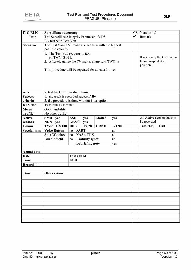
BETA
Test Plan and Test Procedures Document PRAGUE (Phase II) DLR
Issued: 2003-02-16 public Page 69 of 103 Doc ID: d16aii-tpp-10.doc Version 1.0
F1C-ELK Surveillance accuracy CS Version 1.0
Title Test Surveillance Integrity Parameter of SDS Elk test with Test Van
Remark
The Test Van (TV) make a sharp turn with the highest possible velocity
Scenario
1. The Test Van requests to taxi on TWY-G-H-L
2. After clearance the TV makes sharp turn TWY’ s This procedure will be repeated for at least 5 times
If necessary the test run can be interrupted at all position.
Aim to test track drop in sharp turns Success criteria
1. the track is recorded successfully 2. the procedure is done without interruption
Duration 45 minutes estimated Meteo Good visibility Traffic No other traffic Active sensors
SMR NRN
yes yes
ASR GP&C
yes yes
ModeS yes All Active Sensors have to be recorded
Comm. TWR 118,100 DEL 119,700 GRND 121,900 Tech.Freq. TBD Special mns Voice Button no SART no Stop Watches no NASA TLX no Blind Shield no Usability Quest. no Debriefing note yes Actual data
Date Test van id. Time BOB Record id. Time Observation

BETA
Test Plan and Test Procedures Document PRAGUE (Phase II) DLR
Issued: 2003-02-16 public Page 70 of 103 Doc ID: d16aii-tpp-10.doc Version 1.0
Test F1C (Elk Test)
24
06
13
31
F
FF
F
GE
D
C
B
G
A
L
L
L
L
P
M
N
P
R
R
04
22
P
H
HJ
J
APRON N
ORTH
APRONSOUTH
Prague Ruznê
PragAirport-B.dsf
Test F1C (G-J-H-L)

BETA
Test Plan and Test Procedures Document PRAGUE (Phase II) DLR
Issued: 2003-02-16 public Page 71 of 103 Doc ID: d16aii-tpp-10.doc Version 1.0
F1D Surveillance accuracy CS Version 1.0
Title Measuring of Position Renewal Time Out Period (PRTOP)
Remark
Scenario
1. Connect only one sensor to the SDS 2. Switch off the sensor by software tool 3. Switch on the sensor and start stopwatch 4. Stop stopwatch if the target reappeared on the HMI Repeat this test for all sensors for at least 5 times
Aim Measuring the PRTOP after reconnect the sensor Success criteria
The target reappears within several seconds
Duration 90 minutes Meteo Traffic Normal traffic Active sensors
SMR NRN
yes yes
ASR GP&C
yes yes
ModeS yes
Comm. TWR 118,100 DEL 119,700 GRND 121,900 Tech.Freq. TBD Special mns Voice Button no SART no Stop Watches yes NASA TLX no Blind Shield no Test Report yes Debriefing note yes Actual data Date Test van id. Time BOB Record id. Observation Time 1. SMR PRTOP 1.1 Only SMR is connected to the SDS SMR Targets are displayed 1.2 Disconnect SMR from SDS by software 1.3 Reconnect SMR to SDS by software 1.4 Target reappears after seconds 2 ASR PRTOP 2.1 Only ASR is connected to the SDS ASR Targets are displayed 2.2 Disconnect ASR from SDS by software 2.3 Reconnect ASR to SDS by software 2.4 Target reappears after seconds 3 ASCS PRTOP 3.1 Only ASCS is connected to the SDS ASCS Targets are displayed 3.2 Disconnect ASCS from SDS by software 3.3 Reconnect ASCS to SDS by software 3.4 Target reappears after seconds 4 NRN PRTOP 4.1 Only NRN is connected to the SDS NRN Targets are displayed 4.2 Disconnect NRN from SDS by software 4.3 Reconnect NRN to SDS by software 4.4 Target reappears after seconds 5 GP&C PRTOP 5.1 Only GP&C is connected to the SDS GP&C Targets are displayed 5.2 Disconnect GP&C from SDS by software 5.3 Reconnect GP&C to SDS by software 5.4 Target reappears after seconds

BETA
Test Plan and Test Procedures Document PRAGUE (Phase II) DLR
Issued: 2003-02-16 public Page 72 of 103 Doc ID: d16aii-tpp-10.doc Version 1.0
F1D Surveillance accuracy CS Version 1.0
Title Measuring of Position Renewal Time Out Period (PRTOP) Remark Actual data Date Test van id. Time BOB Time 1. SMR PRTOP Measuring 1.1 PRTOP = 1.2 PRTOP = 1.3 PRTOP = 1.4 PRTOP = 1.5 PRTOP = 2. ASR PRTOP Measuring 2.1 PRTOP = 2.2 PRTOP = 2.3 PRTOP = 2.4 PRTOP = 2.5 PRTOP = 3. ASCS PRTOP Measuring 3.1 PRTOP = 3.2 PRTOP = 3.3 PRTOP = 3.4 PRTOP = 3.5 PRTOP = 4. NRN PRTOP Measuring 4.1 PRTOP = 4.2 PRTOP = 4.3 PRTOP = 4.4 PRTOP = 4.5 PRTOP = 5. GP&C PRTOP Measuring 5.1 PRTOP = 5.2 PRTOP = 5.3 PRTOP = 5.4 PRTOP = 5.5 PRTOP =

BETA
Test Plan and Test Procedures Document PRAGUE (Phase II) DLR
Issued: 2003-02-16 public Page 73 of 103 Doc ID: d16aii-tpp-10.doc Version 1.0
F1E Surveillance accuracy CS Version 1.0
Title CWP Performance Measuring the Target Report Latency (TRL) of the CWP
Remark
Scenario
1. Define a marked position on the RWY at the airport.The position has to be identified in the vicinity at the airfield and on the CWP ( Threshold or corner ).
2. Find the corresponding position at the CWP 3. Start the stopwatch if a target is passing the marked
position at the RWY. 4. Stop the stopwatch if the target is passing the marked
position at the screen. Repeat this test for at least 10 times
If necessary locate the Test Van for defining the marked position
Aim Measuring the Target Report Latency Success criteria
Duration 60 minutes Meteo Traffic Normal traffic Active sensors
SMR NRN
Yes yes
ASR GP&C
Yes Yes
ModeS yes
Comm. TWR 118,100 DEL 119,700 GRND 121,900 Tech.Freq. TBD Special mns Voice Button no SART no Stop Watches yes NASA TLX no Blind Shield no Test Report yes Debriefing note yes Actual data Date Test van id. Time BOB Record id. Observation Time 1. TRL = 2. TRL = 3. TRL = 4. TRL = 5. TRL = 6. TRL = 7. TRL = 8. TRL = 9. TRL = 10. TRL =

BETA
Test Plan and Test Procedures Document PRAGUE (Phase II) DLR
Issued: 2003-02-16 public Page 74 of 103 Doc ID: d16aii-tpp-10.doc Version 1.0
F2 Surveillance Classification CS Version 1.0
Title Measuring the Target Detection on the CWP Remark Scenario
1. Observe the CWP 2. Count the detected targets 3. Count the not detected targets 4. Count the false detected targets 5. Count the identified targets 6. Count the number of not continuously tracked targets
If necessary locate the Test Van find a position.
Aim Prove the detection and identification at the CWP Success criteria
All targets should be detected and identified and no false targets detected/ identified
Duration 60 minutes Meteo Good visibility Traffic Normal traffic Active sensors
SMR NRN
yes yes
ASR GP&C
Yes Yes
ModeS yes
Comm. TWR 118,100 DEL 119,700 GRND 121,900 Tech.Freq.
TBD
Special mns Voice Button no SART no Stop Watches no NASA TLX no Blind Shield no Test Report yes Debriefing note yes Actual data Date Test van id. Time BOB Record id. Observation Time 1. No of detected targets PD 2 No of non detected targets 3 No of false detected targets PFD 4 No of identified targets PID 5 No of false classification of targets PFC 6 No of not continuously tracked targets
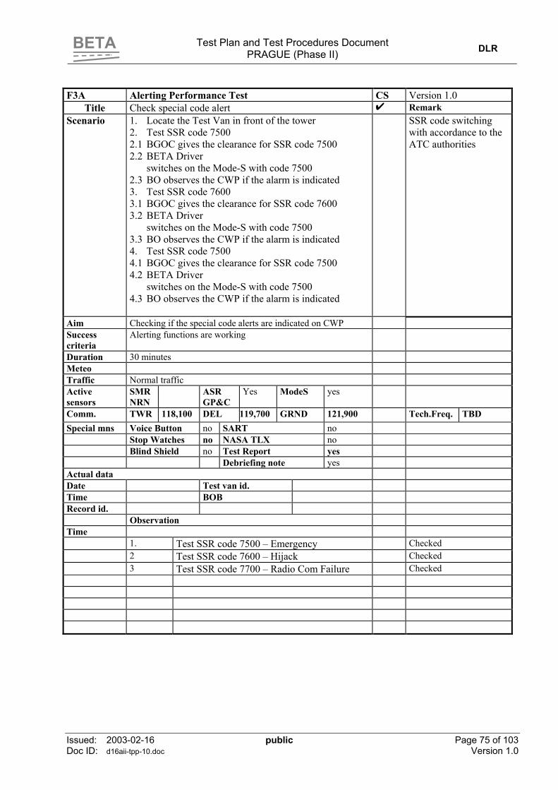
BETA
Test Plan and Test Procedures Document PRAGUE (Phase II) DLR
Issued: 2003-02-16 public Page 75 of 103 Doc ID: d16aii-tpp-10.doc Version 1.0
F3A Alerting Performance Test CS Version 1.0
Title Check special code alert Remark Scenario
1. Locate the Test Van in front of the tower 2. Test SSR code 7500 2.1 BGOC gives the clearance for SSR code 7500 2.2 BETA Driver
switches on the Mode-S with code 7500 2.3 BO observes the CWP if the alarm is indicated 3. Test SSR code 7600 3.1 BGOC gives the clearance for SSR code 7600 3.2 BETA Driver
switches on the Mode-S with code 7500 3.3 BO observes the CWP if the alarm is indicated 4. Test SSR code 7500 4.1 BGOC gives the clearance for SSR code 7500 4.2 BETA Driver
switches on the Mode-S with code 7500 4.3 BO observes the CWP if the alarm is indicated
SSR code switching with accordance to the ATC authorities
Aim Checking if the special code alerts are indicated on CWP Success criteria
Alerting functions are working
Duration 30 minutes Meteo Traffic Normal traffic Active sensors
SMR NRN
ASR GP&C
Yes
ModeS yes
Comm. TWR 118,100 DEL 119,700 GRND 121,900 Tech.Freq. TBD Special mns Voice Button no SART no Stop Watches no NASA TLX no Blind Shield no Test Report yes Debriefing note yes Actual data Date Test van id. Time BOB Record id. Observation Time 1. Test SSR code 7500 – Emergency Checked 2 Test SSR code 7600 – Hijack Checked 3 Test SSR code 7700 – Radio Com Failure Checked

BETA
Test Plan and Test Procedures Document PRAGUE (Phase II) DLR
Issued: 2003-02-16 public Page 76 of 103 Doc ID: d16aii-tpp-10.doc Version 1.0
F3B Alerting Performance Test CS Version 1.0
Title Check conflict alert Remark Scenario
1. Check conflict alert with specific procedure 2. Check restricted area alert with specific procedure 3. Check stop bar crossing alert with specific procedure
This test will be done only for few of alerts to check the proper working of the alarm.
Aim Checking if the special code alerts are indicated on CWP Success criteria
Alerting functions are working
Duration 90 minutes Meteo Good visbility Traffic Normal traffic Active sensors
SMR NRN
Yes Yes
ASR GP&C
Yes Yes
ModeS Yes
Comm. TWR 118,100 DEL 119,700 GRND 121,900 Tech.Freq. TBD Special mns Voice Button no SART no Stop Watches no NASA TLX no Blind Shield no Test Report yes Debriefing note yes Actual data Date Test van id. Time BOB Record id. Observation Time 1. Check conflict alert Checked 2 Check restricted area alert Checked 3 Check stop bar crossing alert Checked

BETA
Test Plan and Test Procedures Document PRAGUE (Phase II) DLR
Issued: 2003-02-16 public Page 77 of 103 Doc ID: d16aii-tpp-10.doc Version 1.0
F4 Testing Planning Performance Parameters CS Version 1.0
Title Check clearance control, hand over control, taxi plans Remark Scenario
1. Check clearance control 2. Check hand over control 3. Check taxi plan computation
Test procedures will be outlined by PAS and NLR
Aim Checking the functionality of the planning parameters Success criteria
Planning functions are working
Duration 120 minutes Meteo Traffic Normal traffic Active sensors
SMR NRN
Yes Yes
ASR GP&C
Yes Yes
ModeS Yes
Comm. TWR 118,100 DEL 119,700 GRND 121,900 Tech.Freq. TBD Special mns Voice Button no SART no Stop Watches no NASA TLX no Blind Shield no Test Report yes Debriefing note yes Actual data Date Test van id. Time BOB Record id. Observation Time 1. Check clearance control 1.1 Number of Alerts raised of non-conformance to clearance Check by PAS 1.2 Number of Alerts raised of non-conformance to clearance Check by PAS 1.3 Number of warnings asking that clearance is due Check by PAS 1.4 Number of false warnings Check by PAS 1.5 Number of alerts raised due to incoherent set of plans Check by PAS 1.6 Number of false alerts on incoherent plans Check by PAS 2. Check hand over control 2.1 Ability of forced shoot/assume hand-over Check by PAS Ability of alerts on uncontrolled aircraft Check by PAS 3 Check taxi plan computation 3.1 Taxi Plan Computation Rate TPCR Check by PAS 3.2 Taxi Plan Computation Response Time TPCRT Check by PAS 3.3 Taxi Plan Prediction Accuracy TTPA No test 3.4 Ability to cover most common taxi routes Check by PAS

BETA
Test Plan and Test Procedures Document PRAGUE (Phase II) DLR
Issued: 2003-02-16 public Page 78 of 103 Doc ID: d16aii-tpp-10.doc Version 1.0
F5-TKOF Testing Guidance Performance Parameters CS Version 1.0
Title Check Onboard HMI and data link with CWP Take Off Procedure
Remark
Scenario
1. Place the Test Van with the onboard HMI at an a/c parking place.
2. Start data link procedure by request at the Test Van
Test procedures will be outlined by PAS and NLR
Aim Checking the functionality of the CWP input and data-link indication
Success criteria
1. Request and acknowledge of the Test Van are displayed immediately
2. Clearances are transmitted and display at the onboard HMI immediately
3. Taxi routes are displayed at the onboard HMI in a proper way
Duration 180 minutes Meteo Traffic Normal traffic Active sensors SMR
NRN Yes Yes
ASR GP&C
Yes Yes
ModeS Yes
Comm. TWR 118,100 DEL 119,700 GRND 121,900 Tech.Freq. TBD
Special mns Voice Button no SART no Stop Watches no NASA TLX no Blind Shield no Test Report yes DALICON Record Yes Debriefing note yes Actual data Date Test van id. Time BOB Record id. Observation Time Procedure Operator at the Test Van Operator at the CWP Check 1 Start Up 1.1 Request Start Up CWP received 1.2 Cleared Start Up HMI clearance received 1.3 WILCO CWP WILCO received 2 Push Back 2.1 Request Push Back CWP received 2.2 Cleared Push Back HMI clearance received 2.3 WILCO CWP WILCO received 3 Request Taxi 3.1 Request Taxi CWP received 3.2 Transmit Taxi Routing HMI Taxi routing shown 3.3 WILCO CWP WILCO received 4 Crossing RWY 4.1 Request Crossing CWP received 4.2 Cleared To Cross HMI clearance received 4.3 WILCO CWP WILCO received 5 Lining Up 5.1 Request Line Up CWP received 5.2 Cleared for Line UP HMI clearance received 5.3 WILCO CWP WILCO received 6 Take Off 6.1 Request Take Off CWP received 6.2 Cleared for Take Of HMI clearance received 6.3 WILCO CWP WILCO received

BETA
Test Plan and Test Procedures Document PRAGUE (Phase II) DLR
Issued: 2003-02-16 public Page 79 of 103 Doc ID: d16aii-tpp-10.doc Version 1.0
F5-LDG Testing Guidance Performance Parameters CS Version 1.0
Title Check Onboard HMI and data link with CWP Landing Procedure
Remark
Scenario
1. Place the Test Van with the onboard HMI at an a/c parking place.
2. Start data link procedure by request at the Test Van
Test procedures will be outlined by PAS and NLR
Aim Checking the functionality of the CWP input and data-link indication
Success criteria
1. Request and acknowledge of the Test Van are displayed immediately
2. Clearances are transmitted and display at the onboard HMI immediately
3. Taxi routes are displayed at the onboard HMI in a proper way
Duration 15 minutes Meteo Traffic Normal traffic Active sensors SMR
NRN Yes Yes
ASR GP&C
Yes Yes
ModeS Yes
Comm. TWR 118,100 DEL 119,700 GRND 121,900 Tech.Freq. TBD
Special mns Voice Button no SART no Stop Watches no NASA TLX no Blind Shield no Test Report yes DALICON Record Yes Debriefing note yes Actual data Date Test van id. Time BOB Record id. Observation Time Procedure Operator at the Test Van Operator at the CWP Check 1 Landing 1.1 Request Taxi CWP received 1.2 Transmit Taxi Routing HMI Taxi routing shown 1.3 WILCO CWP WILCO received 2 Crossing RWY 2.1 Request Crossing CWP received 2.2 Cleared To Cross HMI Taxi routing shown 2.3 WILCO CWP WILCO received Test Protocol and Questionnaires for Operational Tests

BETA
Test Plan and Test Procedures Document PRAGUE (Phase II) DLR
Issued: 2003-02-16 public Page 80 of 103 Doc ID: d16aii-tpp-10.doc Version 1.0
8.2 Test Observer Sheet and Questionnaires for Operational Tests
8.2.1 Test Observer Sheet
BETA
Test Observer Sheet Operational Test at Prague I
Sheet number
BETA Observer (BOB) …………………………. Date: 2002- Test Run No.: UTC Start Time:
UTC End Time: Airport Side Conditions RWY in Use: Outbound: 24 06 31 13 Inbound: 24 06 31 13 Weather Conditions: VIS: Wind Direction: Wind Speed: Further Comments:
BETA Baseline
CEC GEC TEC
Controller: 1 2 3 4 5 6 Non-active Co-Pilot Follow Me Driver Fire Fighter
Operational Test Co –Ordinator Technical Test Co –Ordinator Airport Test Co –Ordinator OTC TTC ATO
Target of interest is not labelled.
Target of interest is not detected.
EFS + All information needed for controlling is available in the EFS. EFS -
DMAN +
D-MAN sequence proposal are executed.
DMAN -
Number of gazes outside:
Comments by the controller
Observations

BETA
Test Plan and Test Procedures Document PRAGUE (Phase II) DLR
Issued: 2003-02-16 public Page 81 of 103 Doc ID: d16aii-tpp-10.doc Version 1.0
8.2.2 Questionnaires
A: Biographical Questionnaire Subject (Controller, Follow me, etc): Date: Test Run: Sheet number: The questions below serve to give us some background information on you, your training background, and your experience with computers. Please note that all personal information will be treated confidently and can not be traced back to any particular person.
Personal information Age:
female
male
Native Language:
Education
Current Employer:
Trained as:
Year of training (Beginning - End):
Professional Experience (in years):
Licences:
Computer Experience
Computer experience since (year):
Weekly time spent with computer (in hrs):

BETA
Test Plan and Test Procedures Document PRAGUE (Phase II) DLR
Issued: 2003-02-16 public Page 82 of 103 Doc ID: d16aii-tpp-10.doc Version 1.0
B: System Usability Scale
Subject (Controller, Follow me, etc): Date: Test Run: Sheet number: Please read carefully through the list of statements on the BETA A-SMGCS. Indicate to which extent you agree with this statement by putting a cross on a scale from 1 (strongly disagree) to 5 (strongly agree).
Strongly disagree
Strongly agree
1. I think that I would like to use
this system frequently.
1 2 3 4 5
2. I found the system unnecessarily complex.
1 2 3 4 5
3. I thought the system was easy to
use.
1 2 3 4 5
1 2 3 4 5
4. I think that I would need the support of a technical person to be able to use this system.
5. I found the various functions in this system were well integrated.
1 2 3 4 5
6. I thought there was too much
inconsistency in this system.
1 2 3 4 5
1 2 3 4 5
7. I would imagine that most people would learn to use this system very quickly.
1 2 3 4 5 8. I found the system very difficult to use.
9. I felt very confident using the
system.
1 2 3 4 5
1 2 3 4 5
10. I needed to learn a lot of things before I could get going with the system.
If you have any additional comments, please add them here:

BETA
Test Plan and Test Procedures Document PRAGUE (Phase II) DLR
Issued: 2003-02-16 public Page 83 of 103 Doc ID: d16aii-tpp-10.doc Version 1.0
C: SART DATA CAPTURE SHEET
Subject (Controller, Follow me, etc): Date: Test Run: Sheet number:
SART SCALE ( = 3-D SART Dimension)
1. Demand on Attentional Resources How demanding is the task on your attentional resources? Is it excessively demanding (high) or minimally demanding (low)?
2. Instability of Situation How changeable is the situation? Is the situation highly unstable and likely to change suddenly (high), or is it very stable and straight forward (low)?
3. Complexity of Situation How complicated is the situation? Is it complex with many interrelated components (high) or is it simple and straightforward (low)?
4. Variability of Situation How many variables are changing in the situation? Are there a large number of factors varying (high) or are there very few variables changing (low)?
5. Supply of Attentional Resources How much of your attentional resources are you supplying to the situation? Are you making the greatest possible effort (high) or giving very little attention (low)?
6. Arousal How aroused are you in the situation? Are you alert and ready for activity (high) or do you have a low degree of alertness (low)?
7. Concentration of Attention How much are you concentrating on the situation? Are you bringing all your thoughts to bear (high) or is your attention elsewhere (low)?
8. Division of Attention How much is your attention divided in the situation? Are you concentrating on many aspects of the situation (high) or focussed on only one (low)?
9. Spare Mental Capacity How much mental capacity do you have to spare in this situation? Do you have sufficient to attend to many new variables (high) or nothing to spare at all (low?)
10. Understanding of Situation How well do you understand the situation? Do you understand almost everything (high) or virtually nothing (low)?
11. Information Quantity How much information have you gained about the situation? Have you received and understood a great deal of knowledge (high) or very little (low)?
12. Information Quality How good is the information you have gained about the situation? Is the knowledge communicated very useful (high) or is it of very little use (low)?
13. Familiarity with Situation How familiar are you with the situation? Do you have a great deal of relevant experience (high) or is it a new situation (low)?
14. Situational Awareness How good was your awareness of the situation? Do you have a complete (high) or a poor grasp of the situation (low)?
low high
low high
low high
low high
low high
low high
low high
low high
low high
low high
low high
low high
low high
low high

BETA
Test Plan and Test Procedures Document PRAGUE (Phase II) DLR
Issued: 2003-02-16 public Page 84 of 103 Doc ID: d16aii-tpp-10.doc Version 1.0
D: NASA TLX RATING SHEET
Subject (Controller, Follow me, etc): Date: Test Run: Sheet number: INSTRUCTIONS: On each scale, place a mark that represents the magnitude of that factor in the task you just performed.
LOW HIGH MENTAL DEMAND
LOW HIGH PHYSICAL DEMAND
LOW HIGH TEMPORAL DEMAND
PERFECT FAILURE PERFORMANCE
LOW HIGH EFFORT
LOW HIGH FRUSTRATION

BETA
Test Plan and Test Procedures Document PRAGUE (Phase II) DLR
Issued: 2003-02-16 public Page 85 of 103 Doc ID: d16aii-tpp-10.doc Version 1.0
NASA TLX RATING SCALE DEFINITIONS
Title Endpoints Description
MENTAL DEMAND Low / High How much mental activity and perceptual
activity was required (e.g., thinking, deciding, calculating, remembering, searching, etc.)? Was the task easy or demanding, simple or complex, exacting or forgiving?
PHYSICAL DEMAND
Low / High How much physical activity was required (e.g., pushing, pulling, turning, controlling, activating, etc.)? Was the task easy or demanding, slow or brisk, slack or strenuous, restful or laborious?
TEMPORAL DEMAND
Low / High How much time pressure did you feel due to the rate or pace at which the tasks or task elements occurred? Was the pace slow and leisurely or rapid and frantic?
PERFORMANCE Perfect / Failure How successful do you think you were in accomplishing the goals of the task set by the experimenter (or yourself)? How satisfied were you with your performance in accomplishing these goals?
EFFORT Low / High How hard did you have to work (mentally and physically) to accomplish you level of performance?
FRUSTRATION LEVEL
Low / High How insecure, discouraged, irritated, stressed and annoyed versus secure, gratified, content, relaxed and complacent did you feel during the task?

BETA
Test Plan and Test Procedures Document PRAGUE (Phase II) DLR
Issued: 2003-02-16 public Page 86 of 103 Doc ID: d16aii-tpp-10.doc Version 1.0
E: Assessment of BETA A-SMGCS benefits Controller: 1 2 3 4 5 6 7 Date: Sheet number: Please read carefully through the list of statements on the BETA A-SMGCS. Indicate to which extent you agree with this statement by putting a cross on a scale from 1 (strongly disagree) to 5 (strongly agree).
Strongly disagree
Strongly agree
1. The control of aircraft in the test
run was very safe.
1 2 3 4 5 Comments (if any):
2. BETA A-SMGCS will reduce
air pollution.
1 2 3 4 5 Comments (if any):
3. BETA A-SMGCS will reduce
costs for airports.
1 2 3 4 5 Comments (if any):
4. BETA A-SMGCS will reduce
costs for airlines.
1 2 3 4 5 Comments (if any):
5. BETA A-SMGCS will reduce
costs for ATC providers.
1 2 3 4 5 Comments (if any):
6. BETA A-SMGCS will reduce
costs for passengers.
1 2 3 4 5 Comments (if any):
7. I think that the BETA A-
SMGCS increases airport capacity.
1 2 3 4 5 Comments (if any):
8. In my opinion, the use of the BETA system endangers safety at the airport.
1 2 3 4 5
Comments (if any):

BETA
Test Plan and Test Procedures Document PRAGUE (Phase II) DLR
Issued: 2003-02-16 public Page 87 of 103 Doc ID: d16aii-tpp-10.doc Version 1.0
9. The control of aircraft with the BETA system was very efficient.
1 2 3 4 5
Comments (if any):
1 2 3 4 5 10. I think that the BETA system helped me to maintain good situation awareness.
Comments (if any):
11. The use of the BETA system
makes the controller’s job more difficult.
1 2 3 4 5
Comments (if any):
12. The use of the BETA system
makes the controller’s job more boring.
1 2 3 4 5
Comments (if any):
13. With the BETA system, it was
easier to separate aircraft safely.
1 2 3 4 5 Comments (if any):
14. The BETA system made it
easier to detect potentially problematic situations.
1 2 3 4 5
Comments (if any):
1 2 3 4 5 15. BETA A-SMGCS will not reduce waiting times for aircraft at the airport.
Comments (if any):

BETA
Test Plan and Test Procedures Document PRAGUE (Phase II) DLR
Issued: 2003-02-16 public Page 88 of 103 Doc ID: d16aii-tpp-10.doc Version 1.0
F: Acceptance Questionnaires Controller: 1 2 3 4 5 6 7 Date: Sheet number: Your opinion is very important for the evaluation of BETA. Consequently, we would like you to answer the enclosed questions giving your individual opinion and personal experience with BETA as implemented in this field test. All the individual data of this test, including this questionnaire will be treated in strict confidence. Instructions Please start with filling out your personal identity at the top of this page. The questionnaire contains relevant questions and a number of statements on aspects of the ATC
tasks you performed during the field tests. Most questions are self-explanatory. In a number of cases you will be asked to decide on how much you agree or disagree with a statement, by making a cross in the box that comes closest to your opinion, as shown below.
Please answer all the items in the order that they are given, but do not cross-check your answers to previous. Where applicable, please put any comments to explain your decisions further in the free spaces below the items (overleaf with reference to question number if necessary). Please: work on your own - do not discuss any questions with your colleagues while filling in the questionnaire (you can, of course, discuss them later). Thank you very much for your co-operation and contribution
Example: Towers should be built even higher to give a better view to the controllers.
strongly disagree
disagree slightly disagree
slightly agree
agree strongly agree
The cross mark means that you agree with the idea that towers should be built even higher.

BETA
Test Plan and Test Procedures Document PRAGUE (Phase II) DLR
Issued: 2003-02-16 public Page 89 of 103 Doc ID: d16aii-tpp-10.doc Version 1.0
General
1. The concept of operations for BETA is difficult to understand. strongly disagree
disagree slightly disagree
slightly agree
agree strongly agree
Comment:
2. The BETA procedures were easy to work with. strongly disagree
disagree slightly disagree
slightly agree
agree strongly agree
Comment:
3. It is easy to learn to work with BETA. strongly disagree
disagree slightly disagree
slightly agree
agree strongly agree
Comment:
4. The BETA system will not fundamentally change the way that controllers work. strongly disagree
disagree slightly disagree
slightly agree
agree strongly agree
Comment:
5. The BETA system requires a re-distribution of tasks within the controller team. Strongly Disagree
disagree slightly disagree
slightly agree
agree strongly agree
Comment:
6. Using BETA makes you think differently about the controller tasks. strongly Disagree
disagree slightly disagree
slightly agree
agree strongly agree
Comment:

BETA
Test Plan and Test Procedures Document PRAGUE (Phase II) DLR
Issued: 2003-02-16 public Page 90 of 103 Doc ID: d16aii-tpp-10.doc Version 1.0
7. The BETA system changes routine communication tasks
strongly disagree
Disagree slightly disagree
slightly agree
agree strongly agree
Comment:
8. This field test changed my attitude towards BETA. Strongly Disagree
disagree slightly disagree
slightly agree
agree strongly agree
Comment: Stress
9. You had a good picture of the traffic under your control during the BETA field tests. strongly disagree
disagree slightly disagree
Slightly Agree
agree strongly agree
Comment:
10. The BETA system makes the controller’s job boring. strongly disagree
disagree slightly disagree
slightly agree
agree strongly agree
Comment: Level of Service
11. BETA enabled you to handle more traffic. strongly disagree
disagree slightly disagree
slightly agree
agree strongly agree
Comment:

BETA
Test Plan and Test Procedures Document PRAGUE (Phase II) DLR
Issued: 2003-02-16 public Page 91 of 103 Doc ID: d16aii-tpp-10.doc Version 1.0
12. BETA enabled you to provide the pilots a better level of service. strongly disagree
Disagree slightly disagree
slightly agree
agree strongly agree
Comment:
13. BETA enabled you to execute your tasks more effectively. strongly disagree
Disagree slightly disagree
slightly agree
agree strongly agree
Comment: Safety
14. Working with BETA makes you feel safer. strongly disagree
Disagree slightly disagree
slightly agree
agree strongly agree
Comment:
15. The introduction of BETA will increase the potential of human error. strongly disagree
Disagree slightly disagree
Slightly agree
agree Strongly agree
Comment:
16. The types of human error associated with BETA are different than those associated with normal work.
strongly disagree
disagree slightly disagree
slightly agree
agree strongly agree
Comment:

BETA
Test Plan and Test Procedures Document PRAGUE (Phase II) DLR
Issued: 2003-02-16 public Page 92 of 103 Doc ID: d16aii-tpp-10.doc Version 1.0
Training 17. There was enough training to get familiar with the BETA procedures.
strongly disagree
disagree slightly disagree
slightly agree
agree strongly agree
Comment:
18. There was enough training on the HMI, its rules and its mechanisms. strongly disagree
disagree slightly disagree
slightly agree
agree strongly agree
Comment:
19. The work environment (seating, lighting) was comfortable. strongly disagree
disagree slightly disagree
slightly agree
agree strongly agree
Comment:
20. There were distractions/disturbances from other activities (e.g. visitors) during the tests. strongly disagree
disagree slightly disagree
slightly agree
agree strongly agree
Comment:
21. What were the three best things about these field tests? 1.
2.
3.
22. What were the three worst things about these field tests? 1.
2.
3. End of this questionnaire, thank you for your co-operation.

BETA
Test Plan and Test Procedures Document PRAGUE (Phase II) DLR
Issued: 2003-02-16 public Page 93 of 103 Doc ID: d16aii-tpp-10.doc Version 1.0
G: Overall Assessment Questionnaire Age:
20-29 years 30-39 years 40-49 years 50 & over
Experience:
5 years or less 6-10 years 11-15 years 16-20 years 21-25 years 26 & over
Education (Check highest attained):
0-12 years 12-16 years Over 16 years
Area of expertise:
Engineering Management Other Please specify:
General Job Description:
Airline Manager Air Traffic Controller Airport Manager Pilot

BETA
Test Plan and Test Procedures Document PRAGUE (Phase II) DLR
Issued: 2003-02-16 public Page 94 of 103 Doc ID: d16aii-tpp-10.doc Version 1.0
Military Officer Academia Other Please specify:
Specific Area of Concentration:
A-SMGCS Design/Operation Safety Airport Design/Operation Other Please specify:
Degree of Risk Aversion: How much of a risk taker are you? If someone presents a problem to you and you are not sure about the answer how often will you give an answer even under uncertainty?
I will never try to guess About 20% of the times About 40% of the times About 60% of the times About 80% of the times I will always try to guess
Let’s assume that we have a panel of judges and we want to determine the judgement ability of each of the panel members. Effectively what we want to do is to be able to give more credibility (weight) to the decisions of the best judges and less weight to the worst judges. One theory states that the weight (W) assigned to a judge should depend on the consistency of his/her decisions, the knowledge that he/she posses of the topic in question as well as his/her personal balance. The term personal balance, refers to the relative absence from specific biases in a patters of choices a judge makes. Expressed in simple terms:
W = KA + KB + KC W = weight assigned to judge’s decision KA = factor expressing the importance of consistency of the judge’s decision KB = factor expressing the importance of knowledge of the judge concerning the topic in question KC = factor expressing the importance of the judge’s personal balance 1. Do you feel that KA KB and KC have equal importance? Please fill in the proper blank.

BETA
Test Plan and Test Procedures Document PRAGUE (Phase II) DLR
Issued: 2003-02-16 public Page 95 of 103 Doc ID: d16aii-tpp-10.doc Version 1.0
Yes No
2. If your answer is no; on a scale of 0 (no value) to 100 (maximum value) what would you rate each of the
three factors?
KA (consistency) KB (knowledge) KC (personal balance) Total = 100
AHP PAIRWISE COMPARISONS TABLES First Level: Quest.: How much more important is the Effectiveness of an A-SMGCS system in determining its overall performance as compared to its Cost?
Identification of the best A-SMGCS in terms of its Overall Performance
System Effectiveness Cost
System Effectiveness 1 Cost 1
Please rate the amount of knowledge you feel that you have, concerning the answer:
1 2 3 4 5
Second Level: Quest.: How much more important is the contribution of sub-criterion “safety” in determining the effectiveness of an A-SMGCS system as compared to the contribution of sub-criterion “efficiency”?
System Effectiveness Safety Efficiency Working Conditions Environment
Safety 1 Efficiency 1
Working Conditions 1 Environment 1
Please rate the amount of knowledge you feel that you have, concerning the answer:
1 2 3 4 5

BETA
Test Plan and Test Procedures Document PRAGUE (Phase II) DLR
Issued: 2003-02-16 public Page 96 of 103 Doc ID: d16aii-tpp-10.doc Version 1.0
Third Level: Quest.: How much more important is the contribution of indicator “Situational Awareness” in determining the performance of an A-SMGCS system in terms of safety as compared to the contribution of indicator “Number of Misunderstandings”?
Safety Situational Awareness
Number of misunderstandings
Situational Awareness 1
Number of misunderstandings 1
Please rate the amount of knowledge you feel that you have, concerning the answer:
1 2 3 4 5
Quest.: How much more important is the contribution of indicator “Traffic delays” in determining the performance of an A-SMGCS system in terms of efficiency as compared to the contribution of indicator “RWY occupancy time”?
Efficiency Number of R/T
Commu-nication
Duration of R/T
Commu-nication
Number of stops of a/c during taxiing
Duration of stops during taxiing
Holding time for each aircraft holding for line up at the RWY entry point
Usability Head Down
Number of R/T Communication 1 Duration of R/T Communication 1 Number of stops of a/c during taxiing 1 Duration of stops during taxiing 1 Holding time for each aircraft holding for line up at the RWY entry point
1
Usability Head Down 1 Please rate the amount of knowledge you feel that you have, concerning the answer:
1 2 3 4 5
Quest.: How much more important is the contribution of indicator “Level of workload” in determining the performance of an A-SMGCS system in terms of working conditions as compared to the contribution of indicator “Acceptance of the System”?
Working Conditions
Level of workload
Acceptance of the
System
Usability of the of the System
Level of workload 1 Acceptance of the System 1 Usability of the System 1
Please rate the amount of knowledge you feel that you have, concerning the answer:

BETA
Test Plan and Test Procedures Document PRAGUE (Phase II) DLR
Issued: 2003-02-16 public Page 97 of 103 Doc ID: d16aii-tpp-10.doc Version 1.0
1 2 3 4 5
Quest.: How much more important is the contribution of indicator “Development Cost” in determining the cost of an A-SMGCS system as compared to the contribution of indicator “Transition Cost”?
System Cost Development Cost Transition Cost Operational Cost Maintenance Cost Training Cost
Development Cost 1 Transition Cost 1 Operational Cost 1 Maintenance Cost 1 Training Cost 1
Please rate the amount of knowledge you feel that you have, concerning the answer:
1 2 3 4 5
Fourth Level: Safety Indicators Quest.: How does BETA system performs in terms of the indicator “Situational awareness” as compared to the performance of the Baseline System?
Alternative System
Situational Awareness
Number of misunderstandings
Alternative System
BETA System
Baseline System
Please rate the amount of knowledge you feel that you have, concerning the answer:
1 2 3 4 5
Efficiency Indicators Quest.: How does BETA system performs in terms of the indicator “Traffic Delays” as compared to the performance of the Baseline System?
Alternative System
Number of R/T Commu-
nication
Duration of R/T Commu-
nication
Number of stops of a/c during taxiing
Duration of stops during taxiing
Holding time for each aircraft holding for line up at the RWY entry point
Usability Head Down
Alternative System
BETA System
Baseline System
Please rate the amount of knowledge you feel that you have, concerning the answer:
1 2 3 4 5

BETA
Test Plan and Test Procedures Document PRAGUE (Phase II) DLR
Issued: 2003-02-16 public Page 98 of 103 Doc ID: d16aii-tpp-10.doc Version 1.0
Working Conditions Indicators Quest.: How does BETA system performs in terms of the indicator “Level of workload” as compared to the performance of the Baseline System?
Alternative System
Level of workload
Acceptance of the
System
Usability of the of the System
Alternative System
BETA System
Baseline System
Please rate the amount of knowledge you feel that you have, concerning the answer:
1 2 3 4 5
Cost Indicators Quest.: How does BETA system performs in terms of the indicator “Development Cost” as compared to the performance of the Baseline System?
Alternative System
Development Cost
Transition Cost
Operational Cost
Maintenance Cost
Training Costs
Alternative System
BETA System Baseline System
Please rate the amount of knowledge you feel that you have, concerning the answer:
1 2 3 4 5
H: Misunderstandings Measurement Tool (NLR)3
3 Is still missing.

BETA
Test Plan and Test Procedures Document PRAGUE (Phase II) DLR
Issued: 2003-02-16 public Page 99 of 103 Doc ID: d16aii-tpp-10.doc Version 1.0
8.2.3 Debriefing Sheet for single BETA functions 1. What comments do you have regarding the Surveillance Display?
………………………………………………………………………………………………….. ………………………………………………………………………………………………….. ………………………………………………………………………………………………….. ………………………………………………………………………………………………….. 2. What comments do you have regarding the EFS?
………………………………………………………………………………………………….. ………………………………………………………………………………………………….. ………………………………………………………………………………………………….. ………………………………………………………………………………………………….. 3. What comments do you have regarding the new Handover procedure?
………………………………………………………………………………………………….. ………………………………………………………………………………………………….. ………………………………………………………………………………………………….. ………………………………………………………………………………………………….. 4. What comments do you have regarding the clearance monitoring alerts?
………………………………………………………………………………………………….. ………………………………………………………………………………………………….. ………………………………………………………………………………………………….. ………………………………………………………………………………………………….. 5. What comments do you have regarding the routing function?
………………………………………………………………………………………………….. ………………………………………………………………………………………………….. ………………………………………………………………………………………………….. ………………………………………………………………………………………………….. 6. What comments do you have regarding the data link clearances?
………………………………………………………………………………………………….. ………………………………………………………………………………………………….. ………………………………………………………………………………………………….. …………………………………………………………………………………………………..

BETA
Test Plan and Test Procedures Document PRAGUE (Phase II) DLR
Issued: 2003-02-16 public Page 100 of 103 Doc ID: d16aii-tpp-10.doc Version 1.0
7. What comments do you have regarding the D-MAN?
………………………………………………………………………………………………….. ………………………………………………………………………………………………….. ………………………………………………………………………………………………….. ………………………………………………………………………………………………….. 8. What comments do you have regarding the route deviation alert function?
………………………………………………………………………………………………….. ………………………………………………………………………………………………….. ………………………………………………………………………………………………….. 9. What comments do you have regarding the RWY incursion alert function?
………………………………………………………………………………………………….. ………………………………………………………………………………………………….. ………………………………………………………………………………………………….. 10. What comments do you have regarding the panning alerts?
………………………………………………………………………………………………….. ………………………………………………………………………………………………….. …………………………………………………………………………………………………..

BETA
Test Plan and Test Procedures Document PRAGUE (Phase II) DLR
Issued: 2003-02-16 public Page 101 of 103 Doc ID: d16aii-tpp-10.doc Version 1.0
8.3 References [1] BETA
OPERATIONAL TEST CONCEPT BETA DELIVERABLE D03-OCD-1.0, BRAUNSCHWEIG, DLR, 2000
[2] BETA GENERAL TEST CONCEPT. BETA DRAFT VERSION D10-GTC-0.3, AMSTERDAM, THE NETHERLANDS, NLR 2001
[3] BETA TEST HANDBOOK BETA DELIVERABLE D33-THE-0.2, BRAUNSCHWEIG, DLR 2001
[4] BROOKE, J. SUS: A ‘QUICK AND DIRTY’ USABILITY SCALE. IN: W. JORDAN ET AL. (EDS.), USABILITY EVALUATION IN INDUSTRY. LONDON: TAYLOR AND FRANCIS 1996
[5] ENDSLEY, M.R. TOWARDS A THEORY OF SITUATION AWARENESS. HUMAN FACTORS, VOL. 37, PP.32-64, 1995
[6] EUROCAE WORKING GROUP 41 MASPS FOR A-SMGCS, ED-87A, 2001 JANUARY
[7] KINNERSLY, S.R. OBJECTIVE MEASURES OF ATM SYSTEM SAFETY: LITERATURE SURVEY INTEGRA, JANUARY 2000
[8] TAYLOR, R.A. SITUATIONAL AWARENESS RATING TECHNIQUE (SART): THE DEVELOPMENT OF A TOOL FOR AIRCREW DESIGN. IN: PROCEEDINGS OF THE AGARD AMP SYMPOSIUM: SA IN AEROSPACE OPERATIONS, AGARD CP, 478. NEUILLY-SUR-SEINE, FRANCE 1989
[9] ZENZ, H. P. VERMESSUNG EINES D-GPS- SYSTEMS IM FLUGHAFENNAHBEREICH DLR IB 112 –95/08, DEZEMBER 1995
[10] ZENZ, H. P.; KLEIN, K.; HAENSEL, H.; BETHKE, K. H.; PREDEMONSTRATION I AT BRAUNSCHWEIG DEFAMM D-PBE101.DOC, 1999 OCTOBER
8.4 List of Figures Figure 2-1: Overall System Block Diagram for Prague..................................................................................... 6 Figure 4-1: Evaluation Methodological Framework for the BETA System.................................................... 13 Figure 5-1: Scenario for Functional Performance Tests F1............................................................................. 22 Figure 6-2: Tower Arrangement during Test Run ........................................................................................... 57 Figure 6-3: Apron Arrangement during Test Runs.......................................................................................... 59 Figure 7-1 Hierarchical Decomposition of the BETA System Evaluation Problem ....................................... 61
8.5 List of Tables Table 3-1: Responsibilities for the Test Tools................................................................................................. 11 Table 5-1: BETA Test Equipment and Human Actors involved in F1 Tests .................................................. 20 Table 5-2: Confidence Level Coefficients....................................................................................................... 21 Table 5-3: BETA Test Equipment and Human Actors involved in F2 Tests .................................................. 24
BETA
Test Plan and Test Procedures Document PRAGUE (Phase II) DLR
Issued: 2003-02-16 public Page 102 of 103 Doc ID: d16aii-tpp-10.doc Version 1.0
Table 5-4: BETA Test Equipment and Human Actors involved in F3 Tests .................................................. 27 Table 5-5: BETA Test Equipment and Human Actors involved in F4 Tests .................................................. 29 Table 5-6: BETA Test Equipment and Human Actors involved in F5 Tests .................................................. 30 Table 5-7: Test Tools for Functional Tests...................................................................................................... 32 Table 6-1: Combination of experimental variables ......................................................................................... 35 Table 6-2: Duty Roster of Prague Controller................................................................................................... 38 Table 6-3: Test Plan......................................................................................................................................... 39 Table 6-4: Controllers associated with the Test Conditions ............................................................................ 40 Table 6-5: Indicators and Measuring Instruments ........................................................................................... 45 Table 6-6: Assessment of indicators during Case Studies ............................................................................... 55 Table 6-7: BETA Test Equipment and Human Actors involved..................................................................... 56 Table 6-8: Test Staff Needed........................................................................................................................... 57 Table 7-1 Characteristics of the Indicators ...................................................................................................... 62 Table 8-1: Acronyms and Abbreviations...................................................................................................... 103
8.6 Acronyms and Abbreviations A/c Aircraft ACC Area Control Centre ADS-B Automatic Dependence Surveillance Broadcast APN Apron Control (responsible for the apron areas) APP Approach Control ARMI Aircraft Registration Mark Identification AS A-SMGCS Airborne System ASCII American Standard Code for Information Interchange A-SMGCS Advanced Surface Movement Guidance and Control System ASR Airport Surveillance Radar ATC Air Traffic Control ATOPS A-SMGCS Testing of Operational Procedures by Simulation (EC project of 4th
Framework Programme) ATS Air Traffic Services Authority BETA Operational Benefit Evaluation by Testing an A-SMGCS BWE Research Airport Braunschweig CD Clearance Delivery CNS Communication, Navigation, Surveillance CS Case Study CWP Controller Working Position DAS Daten-Anzeige-System (Data Display System) DEB Debriefing DEFAMM Demonstration Facilities for Airport Movement Management (EC project of 4th
Framework Programme) DGPS Differential Global Positioning System D-MAN Departure Manager EFPS Electronic Flight Progress Strip EOBT Estimated Off Block Time ETA Estimated Time of Arrival ETD Estimated Time of Departure FP Flight Plan FPS Flight Progress Strip GND Ground Control (normally: ATC responsible for Start-up clearance and outbound
traffic) GP&C Global Positioning and Communication System H Hypothesis HAM Hamburg Airport

BETA
Test Plan and Test Procedures Document PRAGUE (Phase II) DLR
Issued: 2003-02-16 public Page 103 of 103 Doc ID: d16aii-tpp-10.doc Version 1.0
HMI Human Machine Interface ID Identification Code (e.g. Registration Mark, 24Bit Aircraft Address, Flight No.) IFR Instrument Flight Rules MASPS Minimum Aviation System Performance Standards MTOW Maximum Take-off Weight NRN Nearrange Radar Network OC Operational Concept ON Observer’s Notes PRG Airport Prague Ruzynĕ PSR Primary Surveillance Radar QAR Quick Access Recorder QUE Questionnaire R/T Radio Telephony RTS Regular Traffic Study RWY Runway SAGAT Situation Awareness Global Assessment Technique SART Situation Awareness Rating Technique SDS Surveillance Data Server Squawk Transponder Mode a/c Code SSR Secondary Surveillance Radar SUC Start-Up controller/Clearance Delivery TWR Tower Control (normally: ATC for RWY and inbound traffic) TWY Taxiway V-BC Voice Button Counter VDL VHF Data Link VEX Video Extractor VFR Visual Flight Rules VIP Very Important Person VIS Visibility WP Work package
Table 8-1: Acronyms and Abbreviations


