Bertec Workbookbertec.com/uploads/pdfs/manuals/Bertec Workbook.pdf · Workbook Program...
83
Bertec Workbook Program Documentation Version 1.2.0 March 2014
Transcript of Bertec Workbookbertec.com/uploads/pdfs/manuals/Bertec Workbook.pdf · Workbook Program...

Bertec Workbook Program Documentation
Version 1.2.0 March 2014

Bertec Corporation Bertec Workbook
ii
Copyright © 2009-2014 BERTEC Corporation. All rights reserved. Information in this document is subject to change without notice. Companies, names, and data used in examples herein are fictitious unless otherwise noted. No part of this document may be reproduced or transmitted in any form or by any means, electronic or mechanical, for any purpose, without express written permission of BERTEC Corporation or its licensees. Bertec Workbook, BalanceCheck, BalanceCheck Trainer, BalanceCheck Screener, FallTrack, "Measurement Excellence", "Dominate Your Field", BERTEC Corporation, and their logos are trademarks of BERTEC Corporation. Other trademarks are the property of their respective owners.
Printed in the United States of America.
Bertec’s authorized representative in the European Community regarding CE: MIE Medical Research Ltd. 6 Wortley Moor Road, Leeds LS124 JF, United Kingdom Phone: +44-113-279-3710, Fax: +44-113-231-0820

Bertec Corporation Bertec Workbook
iii
Bertec Corporation Software and Firmware License Clause 1 Subject of the Agreement 1.1 The License granted pursuant to this Agreement pertains to any and all software and firmware contained on or in all associated hardware, equipment, and systems
developed and produced by Licensor (“Product” or “Products”). 1.2 The terms and conditions of the Agreement grant the use of one or several Licenses for the software package imbedded in any of Licensor’s Products and/or the
firmware associated with Licensor’s Products (“License”). 1.3 Licensor grants to Licensee a nonexclusive, nontransferable License, without the right to sublicense, distribute, or modify, for use by Licensee and its designated
employees of Licensor’s Products as delivered. 1.4 The License granted to Licensee shall terminate immediately if Licensor violates any of the terms and conditions set forth in the Agreement. Clause 2 Rights of Ownership/Title 2.1 Licensor’s Products are copyright protected. Licensor retains all rights, title, and ownership to the Product and all subsequent full or partial copies and derivatives of
the Product made by Licensee or Licensor, including translations, compilations, partial copies, modifications, updates, and know-how connection therewith, regardless of the form or media in or on which the same may exist. The License does not constitute a sale of the Product and Licensee shall not have the right to reproduce the Product in any manner or form whatsoever. Licensee is specifically prohibited from reverse engineering/development any segment or form of the Product and is further prohibited from deriving or developing a source code equivalent to any segment of the Product. Upon termination of the Agreement, for any reason whatsoever, Licensee shall destroy the Product and certify the destruction, in writing, to Licensor.
2.2 Upon taking delivery of the Product, the Licensee does not become the legal owner, but merely receives the rights of use the Product, as restricted by this Agreement.
2.3 The License does not grant the Licensee the right to use Licensor’s corporate name, trade name, fictitious name, logos, copyrights, artwork, or any property rights associated with the Licensor.
Clause 3 Rights of Usufruct 3.1 Licensor grants to Licensee the right to use the Products at a specified location, in an environment suited for the Products. Use of the Products at a branch office,
subsidiaries, or associated companies is not permitted without the express written consent of the Licensor. 3.2 Licensee is not permitted to make a second copy of the Product for a floating license or for backup purposes. 3.3 The Licensee is strictly prohibited from translating, duplicating, manipulating, reformatting, or decoding the Product. Should Licensor become aware of a violation of
the aforegoing terms, Licensor reserves the right to take legal action or file for an injunction. It is strictly forbidden to pass the Product on to third parties or Licensor’s competitors, their employees, representatives, or agents for their use or demonstrations.
Clause 4 Confidentiality 4.1 Any and all information, technical data, or know-how related to the Product developed by Licensor or Licensee, shall be categorized as confidential information
owned by the Licensor. Licensee shall take all reasonable precautions to protect all confidential information associated with or developed for Licensor’s Products. Licensee shall not disclose Licensor’s confidential information to any third party without the written permission of Licensor. Licensee agrees that any disclosure of Licensor’s confidential information will cause irreparable harm to the Licensor and will subject the improper disclosure to immediate injunctive proceedings.
Clause 5 Delivery, Installation, Training and Assistance 5.1 The Product shall be delivered to Licensee as specified in the Purchase Order documentation and the Acceptance issued by Licensor. 5.2 If specified in the Purchase Order documentation, the Licensor will provide assistance in installation and training. Clause 6 Warranty 6.1 The Licensor warrants that the Product will perform in accordance with its written documentation and that it has the right to grant the License(s) provided for herein
and that the use of the Product will not infringe the intellectual property rights of any third party. 6.2 Licensor warrants to Licensee that it is the legal owner of the Products and the same are delivered to Licensee free of any liens or restrictions. 6.3 The Products are delivered to Licensee pursuant to the warranty terms and conditions set forth on Licensor’s Purchase Order documentation. 6.4 Should Licensee discover any malfunctions in the Product, it shall immediately notify the Licensor via electronic communication, and Licensor shall use its best efforts
to correct the Product so that operations are in compliance with the Purchase Order terms and conditions and Licensor’s warranty. The warranty granted to Licensee shall be void if Licensee or its agents modify the Product or if the Product is used by Licensee outside the scope for which the Product is designed or the Product is operated in an environment which causes damage to the Product.
6.5 In reporting Product errors or malfunctions, Licensee shall provide full details of how the errors manifest themselves and present the information in such a way that the errors can be reproduced by Licensor. If necessary, Licensor shall be granted access to Licensee’s premises to analyze the source of the errors/malfunctions. Once the errors have been corrected a record shall be produced and both parties will certify that the Products are fully operational and in compliance with the Purchase Order documentation.
Clause 7 Limitation of Liability 7.1 Licensor’s maximum liability for any claims, damages, actions or causes of action, arising out of this Agreement, shall be limited to the original cost of the Product.
NEITHER PARTY SHALL BE LIABLE TO THE OTHER OR THIRD PARTIES FOR ANY INDIRECT, SPECIAL, INCIDENTAL, PUNITIVE, OR CONSEQUENTIAL DAMAGES, INCLUDING LOST PROFITS, ARISING OUT OF OR RESULTING FROM THIS AGREEMENT EVEN IF THE OTHER PARTY HAS BEEN ADVISED OF THE POSSIBLE EXISTENCE OR DEVELOPMENT OF SUCH DAMAGES. THE FOREGOING SHALL APPLY REGARDLESS OF THE NEGLIGENCE OR OTHER CONDUCT OF EITHER PARTY AND REGARDLESS OF WHETHER SUCH LIABILITY ARISES IN CONTRACT, NEGLIGENCE, TORT, OR ANY OTHER THEORY OF LEGAL LIABILITY. THE ENTIRE RISK FOR THE PERFORMANCE, NON-PERFORMANCE OR RESULTS OBTAINED FROM USE OF THE PRODUCTS, RESTS WITH LICENSEE.
Clause 8 Extended Warranty 8.1 Extended warranty protection is offered to Licensee pursuant to Licensor’s extended warranty terms and conditions set forth in a separate document. Clause 9 Maintenance 9.1 If requested by Licensee, Licensor shall provide the maintenance which may be necessary for proper operation of the Products. Clause 10 Indemnification 10.1 Licensee shall indemnify and hold Licensor harmless from and against any and all claims, actions, suits, liabilities, judgments, losses, damages, attorneys’ fees, and
other expenses of every nature and character arising out of the use of the Products by Licensee and/or its agents. Clause 11 Export Restrictions 11.1 Licensee shall comply with any export rules and regulations promulgated by any agency of the U.S.A. Licensee indemnifies and holds Licensor harmless against all
losses, damages, penalties, or causes of action arising out of any violation of any federal, state, or local statutes, laws, rules, regulations or ordinances by Licensee. Clause 12 Force Majeure 12.1 Strikes, lockouts, riots, terrorism strikes, acts of violence, extreme weather conditions, death, or similar circumstances affecting the Licensor’s staff, directly or
indirectly, shall be deemed force majeure. Should force majeure make it fundamentally more difficult or impossible for Licensor and/or its team to perform its duties as specified in the Purchase Order documentation, Licensor’s performance can be postponed during the force majeure conditions.
Clause 13 License Activation 13.1 Licensee shall not initiate the use of the Product without fully complying with the Product activation procedures prescribed by Licensor. Clause 14 Governing Law 14.1 The validity, performance, construction, and interpretation of this Agreement shall be governed by the laws of the State of Ohio and the United States of America,
excluding conflicts of laws, rules, and regulations.

Bertec Corporation Bertec Workbook
iv
TABLE OF CONTENTS Introduction __________________________________________________________________________ 9
Definitions, Acronyms, and Abbreviations _________________________________________________ 10
Installation and System Setup ___________________________________________________________ 12
Connecting Bertec Devices______________________________________________________________ 14
Windows XP _______________________________________________________________________________ 14
Windows Vista and Windows 7________________________________________________________________ 17
Windows 8 ________________________________________________________________________________ 19
License Keys, Product Activation, and Read-Only Mode ______________________________________ 20
Workbook First-Run Wizard_____________________________________________________________ 20
Program Operation ___________________________________________________________________ 23
The Login Screen ___________________________________________________________________________ 23
The Workbook Interface _____________________________________________________________________ 24 Patients - the Patients tab______________________________________________________________________________ 25 Finding Patients ______________________________________________________________________________________ 25 Creating, Editing, and Deleting Patients ___________________________________________________________________ 25 The Session Timeline __________________________________________________________________________________ 27
Sessions, explained _________________________________________________________________________________ 27 Session Timeline navigation __________________________________________________________________________ 27 Printing and Emailing Reports_________________________________________________________________________ 28
Tests and Trainings - the Testing tab _____________________________________________________________________ 28 Performing tests ___________________________________________________________________________________ 30
Workbook system menu _______________________________________________________________ 32
Configuration screen __________________________________________________________________ 33
General Settings____________________________________________________________________________ 33
Test Settings_______________________________________________________________________________ 34
Additional Fields ___________________________________________________________________________ 36
Test Packages______________________________________________________________________________ 37 To create a Test Package _______________________________________________________________________________ 38 To edit an existing Test Package _________________________________________________________________________ 38
Operators _________________________________________________________________________________ 38
Security Roles______________________________________________________________________________ 40
Database _________________________________________________________________________________ 41 Database Merging ____________________________________________________________________________________ 43
Quick Screening ______________________________________________________________________ 44
Bertec Corporation Bertec Workbook
v
BalanceCheck Support Structure _________________________________________________________ 46
Support Structure Harness and Shoulder Straps ___________________________________________________46 Harness ____________________________________________________________________________________________ 47 Strap Length Adjustment - Suspender and Waist ___________________________________________________________ 48 Waist Strap Buckle ___________________________________________________________________________________ 48 Leg Strap Length Adjustment___________________________________________________________________________ 48 Leg Rings Buckle _____________________________________________________________________________________ 48 Shoulder Straps _____________________________________________________________________________________ 49 Selecting the correct should strap length _________________________________________________________________ 50
Helping the Patient get into the harness _________________________________________________________50
Helping the patient remove the harness _________________________________________________________51
Force plate Platform___________________________________________________________________ 52
Platform Specifics ___________________________________________________________________________52
Adjustable Foot _____________________________________________________________________________53
BalanceCheck Foam (optional) __________________________________________________________ 53 Using the Foam on the Platform ________________________________________________________________________ 53
Positioning the patient’s feet____________________________________________________________ 55
Test Protocol Safety Guidelines & Notes___________________________________________________ 56 End Of Test Report ___________________________________________________________________________________ 57
BalanceCheck Screener ________________________________________________________________ 58
Normal Stability ____________________________________________________________________________58
Perturbed Stability __________________________________________________________________________59
Limits of Stability____________________________________________________________________________59
Standing Stability Tests_______________________________________________________________________59
Limits of Stability____________________________________________________________________________60
Interpreting the results_______________________________________________________________________61
BalanceCheck Trainer__________________________________________________________________ 69
Static Training ______________________________________________________________________________70 Selecting Training Parameters __________________________________________________________________________ 70 Positioning the Compliant Balance Board _________________________________________________________________ 71 Positioning the Feet __________________________________________________________________________________ 71 Operational Steps____________________________________________________________________________________ 72
Weight Shift Training ________________________________________________________________________73 Selecting Training Parameters __________________________________________________________________________ 73 Positioning the Feet __________________________________________________________________________________ 73 Operational Steps____________________________________________________________________________________ 74
Explore Base of Support Training - Accuracy ______________________________________________________75

Bertec Corporation Bertec Workbook
vi
Selecting Training Parameters___________________________________________________________________________ 75 Positioning the Feet___________________________________________________________________________________ 75 Operational Steps ____________________________________________________________________________________ 76
Explore Base of Support Training - Speed________________________________________________________ 77 Selecting Training Parameters___________________________________________________________________________ 77 Positioning the Feet___________________________________________________________________________________ 77 Operational Steps ____________________________________________________________________________________ 78
Limits of Stability Training____________________________________________________________________ 79 Selecting Session Parameters ___________________________________________________________________________ 79 Operational Steps ____________________________________________________________________________________ 80
How do I..? __________________________________________________________________________ 81
Create a new patient? _______________________________________________________________________ 81
Delete an existing patient? ___________________________________________________________________ 81
Delete a test result?_________________________________________________________________________ 81
Add new protocols to the Workbook program?___________________________________________________ 81
Troubleshooting ______________________________________________________________________ 82
Document Revision History _____________________________________________________________ 83
LIST OF FIGURES Windows Vista, Windows 7, and Windows 8 UAC prompt ...............................................................................................................12 Windows Vista and Windows 7 device driver prompt ......................................................................................................................12 Windows XP device driver prompt ....................................................................................................................................................13 Windows XP and connecting Bertec Device ......................................................................................................................................14 XP driver installation .........................................................................................................................................................................14 XP driver installation warning...........................................................................................................................................................15 XP driver installation completed .......................................................................................................................................................15 XP driver installation with Advanced selected. .................................................................................................................................15 Windows XP driver location ..............................................................................................................................................................16 Windows Vista/Windows 7 control panel menu item.......................................................................................................................17 Windows Vista/Windows 7 control panel.........................................................................................................................................17 Windows Vista/Windows 7 Hardware and Sound control panel ......................................................................................................18 Windows Vista/Windows 7 Device Manager....................................................................................................................................18 Windows Vista/Windows 7 Device Manager after successful install................................................................................................18 Windows 8 device list........................................................................................................................................................................19 Initial run setup wizard intro page....................................................................................................................................................20 Initial run import existing data page ................................................................................................................................................21 Initial run units setting ......................................................................................................................................................................21 Initial run system operator................................................................................................................................................................22 Initial setup final page ......................................................................................................................................................................22

Bertec Corporation Bertec Workbook
vii
The Workbook Login screen..............................................................................................................................................................23 The Log Out button...........................................................................................................................................................................23 The Quick Screening button ..............................................................................................................................................................23 The main Workbook program interface............................................................................................................................................24 The name search in use.....................................................................................................................................................................25 The patient information window ......................................................................................................................................................25 The Session Timeline Bar...................................................................................................................................................................27 Example of Session menus ................................................................................................................................................................27 Email and Printer buttons .................................................................................................................................................................28 Testing and Training icons in the Tests tab.......................................................................................................................................28 The Testing tab .................................................................................................................................................................................28 The Tests and Packages drop-down list ............................................................................................................................................29 Selecting a Package of Tests .............................................................................................................................................................30 The Testing tab icons ........................................................................................................................................................................30 Test Start, Stop, and Continue ..........................................................................................................................................................31 Workbook system menu ...................................................................................................................................................................32 Bertec Workbook Configuration Options..........................................................................................................................................33 The Quick Screen button ...................................................................................................................................................................34 Test Settings configuration screen....................................................................................................................................................34 Autostart Countdown .......................................................................................................................................................................35 Additional Fields configuration screen..............................................................................................................................................36 Edit Additional Field window ............................................................................................................................................................36 A required additional field ................................................................................................................................................................37 The Test Packages configuration screen...........................................................................................................................................37 Operators configuration screen ........................................................................................................................................................38 Edit Operator window.......................................................................................................................................................................39 The main Workbook program interface in Single Operator Mode ...................................................................................................39 Security Roles configuration screen ..................................................................................................................................................40 Edit Security Roles window ...............................................................................................................................................................40 Database Maintenance screen .........................................................................................................................................................41 The Quick Screening button ..............................................................................................................................................................44 Quick Screening introduction page...................................................................................................................................................44 Quick Screen buttons ........................................................................................................................................................................45 Harness and shoulder straps.............................................................................................................................................................47 Harness parts identification..............................................................................................................................................................47 Legs rings buckle diagram ................................................................................................................................................................49 Shoulder straps diagram...................................................................................................................................................................49 Should straps to support frame connection diagram .......................................................................................................................50 Leg strap positioning diagram ..........................................................................................................................................................51 Platform diagram with false-color representation ........................................................................................................................... 52 Adjustable foot .................................................................................................................................................................................53 Foam dimensions ..............................................................................................................................................................................53 Placing the foam on platform ...........................................................................................................................................................54 Top positioning guidelines on the platform ......................................................................................................................................55 Position of the feet on the platform..................................................................................................................................................55 Standing Stability test interface........................................................................................................................................................59 Limits of Stability test interface ........................................................................................................................................................60 Anterior-Posterior Sway Range.........................................................................................................................................................62 Lateral Sway Range ..........................................................................................................................................................................62

Bertec Corporation Bertec Workbook
viii
Direction of Max Instability...............................................................................................................................................................63 Stability Score....................................................................................................................................................................................63 Limits of Stability graph ....................................................................................................................................................................64 Limits of Stability ellipse....................................................................................................................................................................64 Examples of Limits of Stability ellipse vs. Standard Limits of Stability circle.....................................................................................64 Primary direction of movement ........................................................................................................................................................65 Limits of Stability Score .....................................................................................................................................................................65 Examples of Limits of Stability ellipse versus Normal Stability - Eyes Open ellipse...........................................................................66 Max Actual Stability Used .................................................................................................................................................................66 Min Actual Stability Used..................................................................................................................................................................67 LoS Stability Score .............................................................................................................................................................................67 Age Matched Normative Data for BalanceCheck Stability Scores (Average ± SD)............................................................................68 Static Training interface....................................................................................................................................................................70 Compliant Balance Board on Balance Platform................................................................................................................................71 Weight Shift Training interface.........................................................................................................................................................73 Explore Base of Support Training - Accuracy interface .....................................................................................................................75 Explore Base of Support Training - Speed interface ..........................................................................................................................77 Limits of Stability Training interface .................................................................................................................................................79 Representation of the Limits of Stability Training target sets...........................................................................................................79

Bertec Corporation Bertec Workbook
9
INTRODUCTION The Bertec Workbook system is designed to provide a common expandable "framework" for both patient Testing and related Training. By using additional add-on protocol modules - such as BalanceCheck Screener or BalanceCheck Trainer - Bertec Workbook can be expanded to serve your needs as your patient base grows and changes.
A singular feature of the Workbook system is the optional ability for the program to share data with other in-office Workbook systems via the Database Merge feature.
To fully use the Workbook system, a Bertec Force Plate or Balance Plate platform should be connected to the computer, and Test or Training protocols will need to be installed for the Workbook system to use. Sensors inside the platform measure the ground reaction forces exchanged between the patient's feet and the surface of the platform. The Workbook system acquires the force data and produces reports showing the patient's ability to maintain balance.
The Workbook system is easy to use. Once the minimal installation and configuration is complete, the system is ready for use with whatever Test or Training protocols you choose. The Workbook system allows the clinician to select which of the installed Tests or Trainings to be performed and in which order, thus tailoring the specific protocol to the specific patient. Instructions, included for each test, specify when to stand on the platform, how to position the feet, and what to do during the test.
All completed Test or Training protocols are captured to a database, and are automatically grouped into sessions in a scrollable timeline. These results can be viewed in an overall Patient Report or in a specific report for a given Test or Training.
Your reseller may have requested modifications and enhancements to the Bertec Workbook program and its components. These changes would be documented by your reseller. If you have any questions about the differences between the documentation herein and your reseller's product, please contact your reseller first.

Bertec Corporation Bertec Workbook
10
DEFINITIONS, ACRONYMS, AND ABBREVIATIONS 95% Confidence Ellipse - The ellipse containing 95% of the Center of Pressure points. It is determined by multiplying the standard deviation of the coordinates of the Center of Pressure points by 1.96.
Anterior-Posterior Sway Range - The amount of movement of the Center of Pressure in the sagittal plane. It is calculated as the projection of the 95% confidence ellipse on the sagittal axis.
BalanceCheck: a previous Bertec software offering that performed balance-related diagnostics and trainings. Bertec Workbook offers the ability to import previous results from BalanceCheck.
BalanceCheck Screener: a Test protocol set containing both Standing Stability and Limits of Stability tests.
BalanceCheck Trainer: a Training protocol set that can be installed to provide training for balance-related problems. These include various Static and Dynamic Training protocols.
Balance plate: a Bertec device that measures pressure and movement that is optimized for balance diagnostics.
Center of Pressure (CoP) - The point on the surface of the BalanceCheck platform through which the ground reaction force acts. It corresponds to the projection of the subject’s Center of Gravity on the platform surface when the subject is motionless.
Center of Pressure Path - The trace of the Center of Pressure points on the platform.
Database: an encrypted file on the computer where the patient information and test results are stored.
Direction of Max Instability - The direction in which the patient is less stable, and therefore most likely to fall. It corresponds to the angle between the patient’s postero-anterior (forward) direction and the major axis of the ellipse. Angles to the left are indicated as negative numbers.
Direction of Min Instability - The direction in which the patient is more stable, and therefore less likely to fall.
Force plate: a Bertec device that measures pressure and movement.
Lateral CoP Excursion - The amount of movement of the Center of Pressure in the lateral plane. It is calculated as the projection of the 95% confidence ellipse on the lateral axis.
Lateral Plane - A vertical plane through the longitudinal axis of the trunk dividing the body into front and back halves.
Limits of Stability - How much the patient can move in the specified direction without losing balance.
LoS - Limits of Stability.
LoS Score - The ratio between the patient's Limits of Stability and the Standard Limits of Stability.
LoS Stability Score - How much of the Patient's Limits of Stability was used by the patient during the Normal Stability - Eyes Open test.
Major Axis - The larger axis of the ellipse.
Max Actual Stability Used - How much of the patient's Limits of Stability was used by the patient in the Normal Stability - Eyes Open test in the patient’s Direction of Maximum Instability.
Max CoP Excursion - The maximum movement of the Center of Pressure in the Direction of Maximum Instability.

Bertec Corporation Bertec Workbook
11
Max Standard Stability Used - How much of the Standard Limits of Stability was used in the patient’s Direction of Maximum Instability.
Min/Max CoP Excursion Ratio - The ratio between the Minimum CoP Excursion and the Maximum CoP Excursion.
Min Actual Stability Used - How much of the patient's Limits of Stability was used by the patient in the Normal Stability - Eyes Open test in the Direction of Minimum Instability.
Min CoP Excursion - The maximum movement of the Center of Pressure in the direction of minimum instability.
Minor Axis - The smaller axis of the ellipse.
Min Standard Stability Used - How much of the Standard Limits of Stability was used in the Direction of Minimum Instability.
Neutral Position of Center of Gravity - The position of the body’s Center of Gravity when the patient is standing at the Neutral Posture.
Neutral Posture - The posture the patient assumes when they are standing erect, at a comfortable position with the feet approximately shoulder-width apart.
Normative Data: a collection of anonymous data that is for a specific group of people, used to compute statistics.
Operator: the person who is operating the program and administering the Test or Training, usually a clinician or physical therapist.
Normal Stability - The patient's ability to stand still on a firm surface in a comfortable position with the feet symmetrically apart.
Package: a collection of Tests and/or Training protocols in a predefined order.
Patient: the person who is the subject of a Test or Training.
Perturbed Stability - The patient's ability to stand still on a foam surface in a comfortable position with the feet symmetrically apart.
Sagittal Plane - A vertical plane through the longitudinal axis of the trunk dividing the body into right and left halves.
Stability Score - How much of the Standard Limits of Stability was used by the patient during the Normal or Perturbed Stability tests.
Standard Limits of Stability - The Limits of Stability for a person of a certain height as defined by NASA (Bioastronautic Data Book, 1962).
Standard Normal Person - A person that has the Standard Limits of Stability.
Test: a single protocol that measures a Patient's responses and abilities, and can analyze the data and report back information.
Training: a single protocol that provides goals for a Patient to achieve and can provide feedback, along with data analysis.

Bertec Corporation Bertec Workbook
12
INSTALLATION AND SYSTEM SETUP Your Bertec Workbook system may have been purchased with a Balance Frame or other accessory. If so, please consult the Balance Frame or other accessory's documentation for the proper installation, configuration, and usage of those products.
Caution: The Bertec Workbook program is designed to be used with a Bertec Balance Plate or Force Plate, or similar devices. These devices are connected to the computer via a USB cable, which can create a tripping hazard. Please use cable guides or raceways, and always route cables to avoid the possibility of patients, operators, and other personnel from snagging on, damaging, or tripping over loose cables.
Before installing the program, be sure that you are logged in as a Windows Administrator, or else you will need to perform a "run-as" function to start the install under your Windows Administrator credentials. If you are unsure, you will need to contact your organization's technical or network support personnel. Note that once the Bertec Workbook program has been installed, it does not need to run as a Windows Administrator for most operations.
To install the Bertec Workbook program, insert the CDROM that contains the Workbook program. Windows should automatically detect the install program and start it for you. If it does not, use Windows Explorer to navigate to your CDROM drive and start the program BertecWorkbookSetup.exe. If you are using Windows Vista, Windows 7, or Windows 8, you will get an additional User Account Control permission required prompt. Windows XP users will not get this warning.
Windows Vista, Windows 7, and Windows 8 UAC prompt
Click the Continue button to proceed past this. The installer will walk you through the installation procedure for the Bertec Workbook program, and will ask you standard questions as to where you would like to install the program (the default is C:\Program Files\Bertec\Workbook), and where you want the icon shortcuts placed in your Start menu.
Part of the installation process is installing device drivers for both older and newer Bertec Balance Plates and Force Plates. Since these device drivers have not been signed off by Microsoft, you may get two warning messages indicating this. Windows Vista, and Windows 7 users will get a message that looks like this:
Windows Vista and Windows 7 device driver prompt

Bertec Corporation Bertec Workbook
13
In order to continue and properly install the device drivers for legacy devices, you will need to click Install this driver software anyway. If you don't click this button, then the device drivers will not be installed and the legacy plate devices will not work. Note that you will see may message twice, and that you will have to click Install this driver software anyway both times.
Windows 8 users will not get this message box, and these legacy drivers will not be installed on this operating system. If you currently have legacy equipment and absolutely must use them with Windows 8, please contact Bertec Corporation for upgrade and replacement options.
Windows XP users will get a similar message box:
Windows XP device driver prompt
In order to continue and properly install the device drivers, you will need to click the Continue Anyway button. If you don't click this button, then the device drivers will not be installed and the plate devices will not work. Note that you may see this message twice, and that you will have to click Continue Anyway both times.

Bertec Corporation Bertec Workbook
14
CONNECTING BERTEC DEVICES Connecting a Bertec Force Plate or Balance Plate for the first time will cause Windows to load the device drivers for it. You may get a message prompt indicating that it is doing so. The actual messages and interaction is different between Windows XP, Windows Vista, Windows 7, and Windows 8.
WINDOWS XP
Connect the plate device to the computer using the supplied USB cable. It does not matter which end you plug in first, however, it is generally easier to plug the cable into the plate and go to the computer and plug that end in, rather than plugging the cable into the computer first.
If this the first time that you are connecting this plate to a specific USB connector on your computer, your Windows XP system will display a message box similar to the following after a few seconds:
Windows XP and connecting Bertec Device
Make sure that the "No, not this time option" is selected, and click the Next button. There is no harm in selecting either of the Yes buttons, but there nothing on Windows Update for these device drivers to use, so it is spending extra time doing nothing.
XP driver installation
Make sure that the "Recommended" option is selected, and then click the Next button. Depending on the device you have connected, you may get a warning message that is the same as what was shown during the installation:

Bertec Corporation Bertec Workbook
15
XP driver installation warning
As during the program installation, you will need to click the Continue button.
When the driver installation is complete, the following should appear:
XP driver installation completed
Click the Finish button.
Under certain conditions, Windows XP will sometimes not be able to automatically install the default drivers for the devices. If this is the case, un-plug and then re-plug in the USB cable, and when the following message box comes up, select the "Advanced" item to let you enter a specific directory:
XP driver installation with Advanced selected.
The device drivers for Bertec hardware are installed with the application, and are in:
C:\Program Files\Bertec\Workbook\Drivers

Bertec Corporation Bertec Workbook
16
Enter that directory, or browse to it using the Browse button. Note that if you are using Windows XP 64 Bit Edition, you will have "Program Files (x64)" instead of just "Program Files".
Windows XP driver location
Note that Windows XP considers each USB connection port on your computer as a new device connection, and will prompt you as above each time you use the port for the first time. To make the procedure easier for you, we recommend that you either use the same USB connection port all the time, or else take the time to "preload" each port by connecting the USB cable to each one and perform the above steps, one port at a time.
Bertec Corporation Bertec Workbook
17
WINDOWS VISTA AND WINDOWS 7
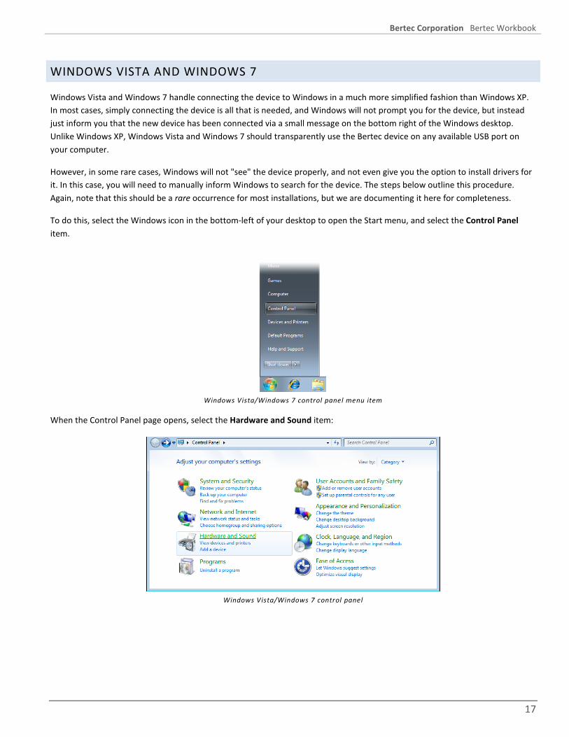
Windows Vista and Windows 7 handle connecting the device to Windows in a much more simplified fashion than Windows XP. In most cases, simply connecting the device is all that is needed, and Windows will not prompt you for the device, but instead just inform you that the new device has been connected via a small message on the bottom right of the Windows desktop. Unlike Windows XP, Windows Vista and Windows 7 should transparently use the Bertec device on any available USB port on your computer.
However, in some rare cases, Windows will not "see" the device properly, and not even give you the option to install drivers for it. In this case, you will need to manually inform Windows to search for the device. The steps below outline this procedure. Again, note that this should be a rare occurrence for most installations, but we are documenting it here for completeness.
To do this, select the Windows icon in the bottom-left of your desktop to open the Start menu, and select the Control Panel item.
Windows Vista/Windows 7 control panel menu item
When the Control Panel page opens, select the Hardware and Sound item:
Windows Vista/Windows 7 control panel

Bertec Corporation Bertec Workbook
18
In the Hardware and Sound control panel, select the Device Manager item on the top-right - this is in the Devices and Printers item, which is the first one in the list:
Windows Vista/Windows 7 Hardware and Sound control panel
In the Device Manager, make sure that the top item is selected (this is your computer), and select the Action menu, and then select the Scan for hardware changes menu item:
Windows Vista/Windows 7 Device Manager
This will make Windows Vista and Windows 7 look for newly attached hardware that it did not automatically "see" before. Windows will install the device drivers with no further prompting from you. After this has completed, the Bertec device should be shown in the Universal Serial Bus controllers section:
Windows Vista/Windows 7 Device Manager after successful install

Bertec Corporation Bertec Workbook
19
WINDOWS 8
Windows 8 does not show a visual indication that a device has been connected, and only provides an audible alert sound that a USB device of some type has been plugged in. If Bertec Workbook indicates that the device is not connected, and Windows 8 makes the typical sound that it does when connecting a USB device, first check if Windows 8 has the driver installed. You can do this by moving the mouse cursor to the upper-right of the Windows 8 Metro Desktop screen, clicking the “gear” icon at the bottom, and click PC Settings. In the list on the left-hand side, click the Devices item. You should see a list of devices like the following:
Windows 8 device l ist
In this example image, the Bertec USB device is identified as an AM6147-E, and the driver is currently unavailable. This typically means that the driver has been uninstalled, and just re-installing Bertec Workbook should resolve it.
If, however, there is no device that resembles the AM6147-E icon or not (it may be called AM6150 or something similar for example), then there is possibly a hardware fault with the device and you will need to contact Bertec Corporation for further assistance and resolution. Before doing this we suggest that you attempt to install the software on a secondary computer and connect the device to it to verify that the problem is not with the actual Windows 8 computer.

Bertec Corporation Bertec Workbook
20
LICENSE KEYS, PRODUCT ACTIVATION, AND READ-ONLY MODE When Bertec Workbook is started without a valid license key, the program will default into “read only mode”. In this mode, you are able to log into the program and view existing test results and reports, but you are not able to create new Patients, edit existing Patients, or start new Tests or Trainings; in addition, several other functional features related to these areas are disabled or unavailable.
To enter a new license key, click the blue Workbook icon on the top right, and select About Bertec Workbook. Click the Add License button and fill out the license key form with your information and then click Register License.
You may have multiple license keys active at any given time. These license keys provide access to protocols and features that would otherwise not be accessible. Please contact your reseller or Bertec Corporation for more information or a trial license key for the produce you are interested in.
Note that Bertec Workbook incorporates technology to check for and block uses of the same license key on multiple systems. If you are planning to migrate your Bertec software and database from one system to another, please contact Bertec Corporation first so that we may provide you with the proper steps and guidance for this procedure.
WORKBOOK FIRST-RUN WIZARD When Bertec Workbook is run for the first time with a valid license key, the program will prompt you with a series of initial configuration options. These include importing previous BalanceCheck and related data, if you have them, your default units of measurements (feet/inches or meters), and setting up a default Administrator operator. This initial setup is only done once, but you can access the Configuration options from the application menu icon that is on the top right-hand side of the Workbook screen.
Initial run setup wizard intro page
The first page lets you know what is going on, and provides the option to either continue or cancel. If you press Cancel at this time, the Workbook program will use the default English measurement and Administrator account. Clicking Next will proceed to the Import Existing Data page.

Bertec Corporation Bertec Workbook
21
Initial run import existing data page
The Import Existing Data page will let you import data from previous versions of Bertec BalanceCheck-related products, including BalanceCheck, BalanceCheck Screener, BalanceCheck Trainer, FallTrack, and Sparta Sports. It will not import data from a Bertec Workbook database – database merging is handled by the system in a completely different manner; see the Database Merging section for more information.
The import procedure will not destroy, delete, or change the existing data files from the previous versions. Note that this import procedure is a one-way, one-time-only process: once this wizard has completed, data can no longer be imported, and there is no method to export the data back to the previous program versions.
The Import Existing Data page will automatically discover previously installed versions of the BalanceCheck programs and their variations. If it does not, or it finds it in a location you know is wrong, use the "browse" buttons to the right of the filenames ( ) to pick the proper files.
If you do not wish to import the previous data, make sure that the checkbox is cleared and press the Next button to display the next page. Otherwise, check the box and make sure the filenames are correct and click Next. The import procedure takes a few minutes and the next page is displayed.
Initial run units setting
By default, Bertec Workbook will use the Imperial (feet, inches, pounds) units of measurements to display results - recorded data is always in common units such as Newtons and Meters, never in the selected unit. If your location uses Metric (meters, kilos) then you would choose the other option. Note that this can be changed later in the Configuration - General Settings screen.
Click the Next button to go to the next page in the initial setup.

Bertec Corporation Bertec Workbook
22
Initial run system operator
By default, the super-operator or System Administrator account is called admin with a default password of password. It is strongly recommended that you at least change the password for this account, and you may also want to change the actual logon name from admin to something else. You can add additional Operators in the Configuration - Operators screen.
Make sure that you write down the operator name and password if you change them; otherwise, you will not be able to log into the Workbook program. There is no method to recover mis-typed or forgotten passwords.
Change either or both the Operator Name and/or Password, and click the Next button.
The last page of the initial setup screen just gives you the option to log in used the System Administrator account and perform additional configuration options. If you do not wish to do so, clear the Show the Configuration check box. Click the Finish button to complete the initial setup and show either the Login screen or the Configuration screen.
Initial setup final page

Bertec Corporation Bertec Workbook
23
PROGRAM OPERATION Starting the Bertec Workbook program is done by double-clicking on the Workbook icon on the desktop, which will start the program and bring up the Operator Login screen, where the Operator can log into the program or use the Workbook program icon menu to perform other operations, such as viewing installed add-ons, view system information, and read the help file. Additional add-ons may also add functionality and graphics to the program's interface, so the images that are here may change depending on these add-ons and the Microsoft Windows version that is being used.
THE LOGIN SCREEN
When you start Bertec Workbook, you are presented with a Login screen, which is similar to many that you have seen. Select the Operator to login as from the list – typically, there will be only “admin” listed, unless there has been additional Operators created – and enter the password for that Operator, and click the Login. The application menu icon on the top right-hand side is used to access license information, help, updates, and Configuration options.
The Workbook Login screen
Once the Operator is logged in, the Log Out button on the bottom left becomes active and the logged in user is shown. Clicking the Log Out button at any time will cancel whatever function the Operator is doing, and return to the Login screen.
The Log Out button The Quick Screening button
If you have the proper Test Protocols installed and have configured the program to do so, you may also have a Quick Screening button. This button will automatically log you in as a specific Operator and start a specific set of Tests. This feature is designed to allow for a more ad-hoc interaction between the Patient and the Operator, primarily in a non-clinical setting. See the Quick Screening section for more information about this feature and how to use it.

Bertec Corporation Bertec Workbook
24
THE WORKBOOK INTERFACE
Once an Operator has logged into the program, the Workbook program interface becomes available. Within this, you have access to your Patients List, Tests that a Patient can perform, and the Session Timeline. The main section of the window shows the currently selected report or the default patient information.
The main Workbook program interface
The above image shows that the operator Demo User is logged in, and that the patient John Doe is selected. If the computer has a web cam connected, then the Workbook program can take a picture of the patient and keep it with the patient's record - otherwise, a generic silhouette image is shown. See the Patient Information section for more information about entering and editing the Patient’s information and using a web cam.
In the main section of the above image, the default Patient Information is shown – this includes their name, date of birth, last recorded weight, address, notes, and etc. Directly above this is the Session Timeline, which shows global Information report options and grouped sets of tests ordered by date. The Session Timeline is the main interaction point for an Operator to select Test Report results and display them. See the section on the Session Timeline for more information.
The top right part of the screen contains a few control icons, such as the Bertec Workbook icon where program settings can be found, printing, and emailing. The Quick Screen control buttons may also appear here – see the Quick Screening section.

Bertec Corporation Bertec Workbook
25
PATIENTS - THE PATIENTS TAB
Clicking on any of the Patients in the Patient List will select that patient, showing their image if one was taken, their current information is shown, and the Session Timeline will update with their Test results, grouped by date.
The Patient List can be sorted by Most Recently Tested first, so that Patients that you see frequently are at the top; by a Patient's name or just their last name; and by their age. Each sort option can be either ascending or descending.
FINDING PATIENTS
To search for a Patient, click in the Name Search box directly below the patient picture, and type in part or their entire name. The Patient List is automatically filtered and updated to show just the Patients that match the search criteria:
The name search in use
To clear the name search and show all Patients, delete the text in the Name Search box.
CREATING, EDITING, AND DELETING PATIENTS
Changing a Patient's information or creating a new one is done using the Patient List and the Patient Icon - the image with a blue pencil in it. If you select the New Patient item in the Patient List, the image changes to "Click here to start a new patient". Clicking in the box area in either case will display the Patient Information window.
The Patient Information window allows you to enter new patient information, update or correct existing information, add or edit notes, take or replace patient pictures, and delete a patient record.
The patient information window
Here you can enter, edit, or remove patient information, and take a picture using an attached web cam.

Bertec Corporation Bertec Workbook
26
Any fields that are required will be shown in yellow, and the Save Changes button will not allow you to save until you enter them. By default, Patients are not required to have an Identifier (such as an SSN), but if your office or practice requires this, you can turn it on in the Configuration - General Settings page.
The Notes tab is a free-form text entry box, allowing you to enter whatever information that cannot be otherwise easily captured using the form fields.
The Additional Information tab shows a row of fields that the Operator can update with whatever is standard for your clinic or practice. The default fields in here are Treating Physician, Referring Physician, Physical Therapist, Complaints, Diagnosis, and Goals. Using the Configuration screen, you can add, change, or remove the fields that are shown here, and mark any of them as required. For example, you may wish to always have a Referring Physician have some value. See the Configuration - Additional Fields section for more information.
The Save Changes button will do just that. Note that you are allowed to have duplicate patient names.
Don't Save Changes will close the screen without keeping anything you have saved, prompting you to confirm if you have actually made some changes.
Delete Patient will prompt you to make sure you want to do this, and then remove the Patient from the Patient List. It is rare that you will want to do this.
To take a picture of a Patient, you will first need to have a web cam installed. Bertec Corporation has tested many different vendors and has found that almost all of them are equal when it comes to taking this kind of picture. After you click on Turn on Camera, the button will change to Take Picture and the image will show a live feed from the camera. Clicking Take Picture will store the image with the Patient Record, and will be shown when the patient is selected. If there is no picture for the Patient, a generic silhouette image will be displayed.
If you are unable to get your web cam to function with Bertec Workbook, please make sure that the software for it is installed correctly and that it functions outside of Bertec Workbook. On some cameras brands you may need to have the camera software running before Bertec Workbook can access the camera.

Bertec Corporation Bertec Workbook
27
THE SESSION TIMELINE
This Session Timeline is an interactive display of the Tests that a patient has done, represented by blue buttons with a date on them. The Session Timeline is always organized with the most-recent date on the left, with the historic results extending to the right (and in this example, off the screen as indicated by the double chevron).
The Session Timeline Bar
Dates with multiple Sessions or Reports will have a drop-down arrow on them (such as December 30th). Clicking on this will expose a menu showing the possible Reports that can be viewed, grouped by Sessions, Time, and Reports that can be combined.
SESSIONS, EXPLAINED
Sessions are a set of Tests and/or Trainings that were performed together. For example, if the Operator selects a set of packaged test to perform, and the Patient does all of them, and then quits the Testing tab, that is considered a Session. However, if they do only some of the tests, quit, and come back later to do the rest, that is a different session – it may be in the same day, or even within a few minutes of the previous one, but is considered a separate Session.
SESSION TIMELINE NAVIGATION
Navigation in the Session Timeline is done using the mouse. Clicking on a Session button either shows the report for that session (if there are no other sessions or reports within that date ), or if there are multiple possible reports or sessions to show, then a list of choices will be shown:
Example of Session menus
In the above two examples, December 30th has five separate sessions of tests, with the Standing Stability set of tests performed as one Session (in addition, the Standing Stability report combines all four of the test results into a single report); each of these separate Sessions are shown distinct from each other by a blue line. On September 12th, however, all of the tests were performed during the same Session, but the reporting does not combine the test results, so each test result has a separate report.
If there are more Sessions than can be shown than can fit on the screen, a set of double-chevrons appear, indicating that the Operator can click and drag the mouse left or right to bring additional Sessions into view.
The blue “I” icon is the general information icon, and shows reports that can cross Session boundaries, such as Patient Information or a Patient Progress Report for Standing Stability and Limits of Stability.

Bertec Corporation Bertec Workbook
28
PRINTING AND EMAILING REPORTS
You can either Print any report selected through the Session Timeline using the printer icon or pressing control-P on the keyboard, or Email it using the email letter icon or pressing control-E on the keyboard. These icon buttons are located on the top-right of the Workbook program. Emailing will attempt to start your default Internet Email client and attach a PDF version of the report. If you don't have a stand-alone email client - for example, your email is all web-based using something like Google Mail or your ISP's web-based email - then Workbook will generally notice that you cannot email a report and offer you the option to save the PDF file instead, so that you may manually email it yourself.
Printing will print to any attached printer device.
Email and Printer buttons
TESTS AND TRAININGS - THE TESTING TAB
In the context of Bertec Workbook, the results of Test and Training Protocols are the same – results are the captured and computed test data that is logged from attached Bertec devices such as Force Plates and Balance Plates. The only true difference between the two is a semantic one: in general, a Test protocol is done to find a result, whereas a Training protocol is done to achieve a result. For example, there might be a Test protocol to discover if a Patient has a balance problem, and then a Training protocol to work with the Patient to correct the discovered problem and bring them back into a normal balance stance.
The Workbook program provides both a grouping and icon difference so that the Operator can know at a glance which is a Test, and which is a Training.
Testing and Training icons in the Tests tab
To use the Testing tab, you must first have a Patient selected. The Testing tab will not be active if there is no patient selected, or the New Patient entry selected. If Bertec Workbook is running without a valid license and is in read-only mode, the Testing tab will not be displayed at all.
The Testing tab

Bertec Corporation Bertec Workbook
29
At the top of the Testing tab is a drop-down list that has all the Tests protocols that are known to Bertec Workbook, and all of the currently defined Test Packages (see the Configuration - Test Packages for more information about this). Below that is a list of the Tests and/or Trainings that are in the currently selected item in the drop-down list box.
The Notes entry box and the Notes icon allow you to add and edit notes about the tests and their results. These notes are stored separately from the Patient and pertain to just the current Session. Any notes entered are normally displayed as part of the Test report. Clicking the Notes icon will bring up the complete Notes editor, which is a reasonably full-featured WYSIWYG text editor: you can change the text style (bold, italic, underline), justification (left, center, right, full), the size of the text, make the text sub-script or super-script, insert images, and change the text color. Depending on the Test report, you may be able to edit these notes from the report display at a later time.
The Height entry box is where the Operator enters the measured height of the Patient prior to the Test, if it differs from the Patient’s current height. This is recorded both in the Test results data, and in the Patient's record. Some Test Protocols may not perform correctly or not at all without a valid height.
The Start/Restart Test from Top button is used to start tests from the top, resetting the Test progress to uncompleted. The Continue button is used to perform Tests that have not been completed yet (for example, the Patient has left the room for a moment).
Clicking on the Tests and Packages drop-down list will show all the Tests and Training protocols installed in the system, and all the defined Packages (collections of Tests and Training), along with the default option, which is to repeat the last set of Tests or Trainings that the Patient did. This option is useful because it does not require the Operator to remember which Package or Test was selected the last time for the Patient.
The Tests and Packages drop-down list
Selecting one of the items with an icon - Package, Test, or Training - will close the drop-down list and select either the single Test or Training item, or will load the Tests or Training from a Package. For example, if Balance Sensory Screen was selected (part of the BalanceCheck add-on), four Tests would be loaded - Eyes Open on Flat Surface, Eyes Closed on Flat Surface, Eyes Open on Foam Surface, and Eyes Closed on Foam Surface.

Bertec Corporation Bertec Workbook
30
Selecting a Package of Tests
Clicking on a Test in the list will show the test instructions for that Test. The blue arrow shows which test will be started when the Start button is clicked. Clicking on a test prior to clicking the Start button is not required.
At any time you can enter notes about the test session into the Notes field.
Clicking the End of Tests Report will show you the results from this list of Tests, if they have been performed. Otherwise, it will either show an empty result page or the last test results.
The Test list shows the progress of the Tests as they are performed. The currently selected Test is shown with a blue box outlining the Test name. Different icons are also shown:
indicates which test is current or will be started when Start/Restart is clicked.
indicates the test that is currently running.
indicates that the test was stopped for some reason
indicates that the test failed for some reason
indicates that the test completed successfully and the results are in the database. The Testing tab icons
PERFORMING TESTS
To start a test, the Operator can either press the Start From Top button, or double-click on a Test. Starting from the top will perform the Tests in sequence, and if the Auto Advance option in the Configuration screen is turned on, will move to the next test as each one is completed. In addition, if the Auto Start option in the Configuration screen is turned on, a countdown box is shown waits for the Patient to stand still for the configured time before starting the Test. See the Configuration - Test Settings section for information about this feature.
Double-clicking a Test, on the other hand, will not show the Auto Start countdown, since the Operator is starting the test right now. It will, however, use the Auto Advance feature once the test that was double-clicked has completed successfully.
If a Test cannot be completed - for example, the Patient never was on the plate so no data was collected - the Test Protocol will prompt the Operator that the test results were not suitable and that they need to re-try the Test or Training again. This will depend upon the actual Test or Training protocol that is being used.

Bertec Corporation Bertec Workbook
31
Tests will proceed in the order that they are listed until all are completed, at which point the End of Tests Report will be shown, which is the same as the Test Report link in the Timeline display.
If the Testing was interrupted for some reason - the operator clicked Cancel or the program was exited, or the Patients tab was selected and a different Patient was selected - the next time this Patient is selected and the Testing tab is clicked, the Continue with Uncompleted Tests button can be clicked so that any Tests in the package that were uncompleted, failed, or stopped will be started. Any completed tests will be skipped.
When a Test is completed (indicated by the green checkmark), there may be times when the Operator wishes to do that test over or repeat it. By double-clicking on a completed Test, the Operator gets a window asking what they wish to do - Keep the data and start a new test, Delete the data and do it over, or do nothing and ignore the double click.
Clicking the Start/Restart or the Continue buttons will show the Start, Stop, and Cancel Testing buttons, and will lock the Tests and Packages list from being selectable. Some Tests or Training protocols will also provide a "Completed" button, that when clicked, marks the test as "done" even if there is no valid data, and advances to the next one. Otherwise, the Test protocol itself will inform Bertec Workbook that the test has been performed correctly or not.
Test Start, Stop, and Continue
If you have the Auto Start test option turned on, the Workbook program will display a "count-down" timer that is sensitive to the Patient's ability to stand still for the configured amount of time. Both the time required and how sensitive this is are set in the Configuration - Test Settings screen. If you do not have Auto Start turned on, then the Operator will need to click the Start button when the test is ready; even if the Auto Start is on, the Start button can be clicked to start the test anyways.
If the Operator needs to abort the Test, clicking Stop at any time will do so.
The Test itself will indicate to the Workbook program that it has completed successfully, but in some Test protocols or Training situations, the Operator will need or want to do so, and a Completed button is provided.
Some Tests and Trainings will provide additional user inputs, such as test settings, target goals, total runtime, and etc. These settings and user interactions are documented in each add-on Test Protocol.
The End of Tests Report is the same as what would be shown in the Timeline reports. This report is shown automatically once the last Test in the list is completed, regardless of the state of the previous Tests in the list. The Operator can decide to perform any of the other tests before or after the End of Tests Report is shown, even re-doing one or more of them if they so desire.
For specific test and training protocols, such as Limits of Stability or Explore Base of Support, please consult the appropriate sections of the documentation.

Bertec Corporation Bertec Workbook
32
WORKBOOK SYSTEM MENU On the top-right corner of the program window, there is the Workbook icon button, which is the Workbook system menu. Clicking this icon button will display a menu containing a list of actions that can be performed. Note that some actions are not available if there is no Operator logged in, if the Operator has limited access rights, or the license key is missing and the program is working in read-only mode. In addition, some add-on products will add menu items here as an Extras sub-menu.
Workbook system menu
The About Bertec Workbook item will display a screen that shows information about the program, such as version, licensing, installed addons, system information, and support information.
The Help item will display the documentation for the program in PDF form.
If an Operator is logged in, the Change Password item will allow the Operator to change their password. The Operator will need to first type in their current password, and then type in their new one.
The Configuration item shows the Configuration Screen starting with the General Settings item; the Database Maintenance item will also show the Configuration Screen, but will start with the Database item. If the Operator does not have access rights to the Configuration Screen, or if the program is in read-only mode, then this item is unavailable.
The Zero Plate Load item will force the attached device to take whatever weight there is on the device and consider that the new "zero point". Generally, this option should be used only when the plate is reading a weight when there is nothing on it - make sure that there is nothing on the plate, and select this item to zero it.
Some installed protocols will extend the functionality of Workbook by adding features into an Extras menu; this menu item will only show up if and when such protocols are installed. Currently, none of the Bertec protocols install anything into this Extras menu.
If Bertec Workbook is currently running without a valid license and is in read-only mode, then only About Bertec Workbook and the Help menu items will be available.

Bertec Corporation Bertec Workbook
33
CONFIGURATION SCREEN The Configuration screen allows you to change how Bertec Workbook functions, and allows you to perform such actions as creating Packages, adding and deleting Operators, and changing Security options. In addition, you can create Database backups and schedule automatic backups of the database.
To access the Configuration Screen in Bertec Workbook, click the Workbook icon on the top-right and select Configuration. The following screen will appear:
Bertec Workbook Configuration Options
Clicking the icons on the left side of the screen will show different options that are available in the right side of the screen. To keep any changes that are made to the Configuration Screen, click the OK button. To reject the changes and not keep them, click the Cancel button.
GENERAL SETTINGS
The General Settings configuration options are used to change how the program behaves. Here you can configure the Units of Measurements (pounds/feet/inches vs. kilograms/meters/centimeters), the requirement that Patients must have an SSN, if the program should zero the plate for you when it starts or the plate is connected (so that you don't have to click the Zero Plate Load menu item), what the Report Header will be at the top of each report page, and enabling the Quick Screen display.
The Report Header is a fairly complete WYWSIWYG editor. You can change the font size, style, alignment, and color. You can even insert a reference to an image such as your office logo into the header. The image file must be accessible to the Windows computer in order for it to be displayed - the image is not saved in the Report Header, only a reference to it. We recommend that the image is present on the local harddrive.
The Quick Screening option, when enabled, puts a Quick Screen button on the login screen, like such:
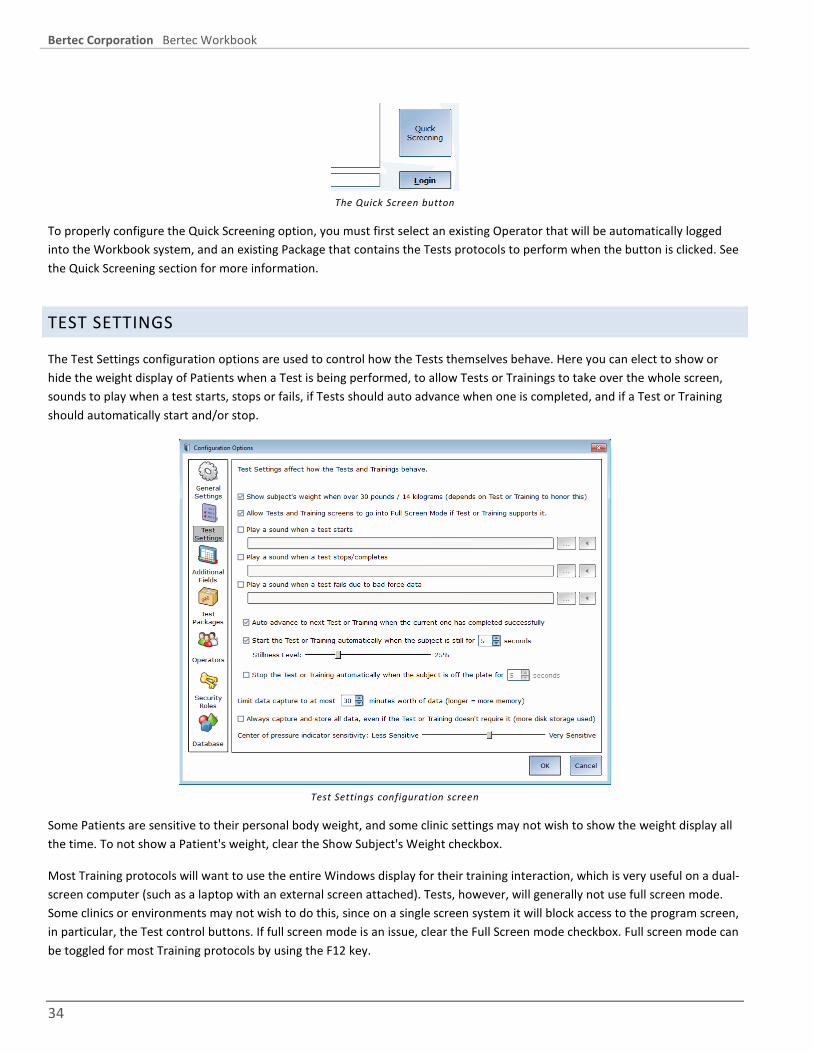
Bertec Corporation Bertec Workbook
34
The Quick Screen button
To properly configure the Quick Screening option, you must first select an existing Operator that will be automatically logged into the Workbook system, and an existing Package that contains the Tests protocols to perform when the button is clicked. See the Quick Screening section for more information.
TEST SETTINGS
The Test Settings configuration options are used to control how the Tests themselves behave. Here you can elect to show or hide the weight display of Patients when a Test is being performed, to allow Tests or Trainings to take over the whole screen, sounds to play when a test starts, stops or fails, if Tests should auto advance when one is completed, and if a Test or Training should automatically start and/or stop.
Test Settings configuration screen
Some Patients are sensitive to their personal body weight, and some clinic settings may not wish to show the weight display all the time. To not show a Patient's weight, clear the Show Subject's Weight checkbox.
Most Training protocols will want to use the entire Windows display for their training interaction, which is very useful on a dual-screen computer (such as a laptop with an external screen attached). Tests, however, will generally not use full screen mode. Some clinics or environments may not wish to do this, since on a single screen system it will block access to the program screen, in particular, the Test control buttons. If full screen mode is an issue, clear the Full Screen mode checkbox. Full screen mode can be toggled for most Training protocols by using the F12 key.

Bertec Corporation Bertec Workbook
35
When a Test starts, stops, or fails, Bertec Workbook can optionally play a sound effect. To so do, check the Play a Sound checkbox for the action, and use the file selection button ( ) to select a file that is stored on your local computer. To play the sound effect to hear what it sounds like, you can click the Play Sound button (to the right of the file selection button).
When a Test completes successfully, the Workbook program can either automatically advance to the next test, or wait for the Operator to select the Test to perform. Setting the Auto Advance checkbox will have Workbook go to the next test when the current one completes.
Often it is difficult for the Operator to correctly gauge when the Patient or subject has achieved a stable point where the Operator can start the test. With the Start Automatically settings, the Workbook system can tell if the Patient or subject has stopped moving for a set period of time, and then start the test when that time has elapsed. When the Start Automatically setting is turned on, the Workbook system will display a countdown indicator. As the Patient or subject stands still long enough within the Stillness Level percentage, the countdown indicator decreases the time left, until zero is reached, and the Test automatically starts. If the Patient moves, the count down time resets. If the Operator wishes to override the autostart and begin the test, they can click the Start Now button. The Cancel Autostart button will dismiss the autostart countdown window.
Autostart Countdown
The Stillness Level percentage ranges from 0% (very sensitive) to 99% (least sensitive). The lower the value the more the Patient must stay still and be centered on the plate; the higher the value the more the Patient can be off-center on the plate and move back and forth. The default value of 25% is suitable for most Patients and Test protocols, but may be adjusted up or down as needs dictate.
In conjunction with the Start Automatically option, there is also the Stop Automatically option; if the patient steps off the plate, the test can automatically end.
By default, Workbook will limit a Test or Training Protocol to run at most for 30 minutes per test. This is fine for most Protocols, but if you have one that you know will take a patient longer than 30 minutes to complete, then increase this. You will probably never need to adjust this value, since it would only affect Protocols that have an "open-ended" run time, such as the Weight Shift Training protocol. Timed tests like the Limits of Stability or Standing Stability tests are not affected by this setting.
By default, Workbook will also limit the data being collected to only store the device data channels that the Test or Training actually needs; with the Always Capture checkbox turned on, Workbook will record all of the device data channels present on the device, regardless of the Protocol needing them or not. For example, if the device has Fz, Mx, and My data channels, and the Protocol only needs Fz, then Workbook will store only the Fz channel if this checkbox is not set. Conversely, if the checkbox is set, then Fz, Mx, and My are stored, which obviously takes 3 times the room in the database and on the disk.
The Center of Pressure display in some Test Protocols (such as Standing Stability and Limits of Stability) can be adjusted to how sensitive they are to initial pressure on the plate. By default, this is approximately 25 pounds of pressure change. Adjusting this slider towards Very Sensitive will make the plate react to less pressure, down to approximately 2 pounds, and adjusting the slider toward Less Sensitive makes it approximately 65 pounds. This has nothing to do with how fast or slow the display updates, it only affects how much pressure on the plate is required to make the Center of Pressure start tracking.

Bertec Corporation Bertec Workbook
36
ADDITIONAL FIELDS
Additional fields allow you to attach extra information to each patient record. Any fields that have the Required column checked are must-have fields and updating or creating patient records will require the Operator to enter values for those fields before the Patient record can be saved.
Additional Fields configuration screen
To edit or delete a field, first click on a field and then either click Edit Field or Delete Field. To create a new Additional Field, click New Field. Edit Field or New Field will bring up a window like this one:
Edit Additional Field window
The Additional Field Name is required, and is shown in the report for the Patient. The optional Description is only shown in the Edit Patient screen and is provided to allow for more information or data guidance.
The Sort Order entry field allows you to control how the Additional Fields are shown in both the Patient report information, and in the Edit Patient screen. If this value is blank it will default to zero. Duplicate Sort Order values, while not recommended, are allowed to occur. In such a case, the list is sorted by Sorted Order and Field name (alphabetical).
The Required checkbox, when checked, will mark the entry in yellow in the Edit Patient screen until the Operator has put something in it, and prevents the Operator from updating the Patient record until this field has a non-blank entry in it. Changing

Bertec Corporation Bertec Workbook
37
an existing Additional Field from non-required to required will not force the Operator to go through every single Patient, only the next time a Patient record is edited (an operation that must directly invoked) will it require the field to be filled in.
A required additional field
In the Additional Fields configuration screen, pressing the Delete Field button will remove access to all existing values in all Patients for the Field being deleted. This button should be used with extreme caution – deleting and then re-creating the field with the same name will not bring back the existing data!
Using the Edit Field button to rename a field (ex: Sample Required to Insurance Card) will not delete all existing values of the Field in Patient records. Existing values will be kept with the renamed field.
TEST PACKAGES
Test Packages allow you to create commonly performed tests into a named collection. The Operator can then select the Package from the test list and the tests in the package will be performed in the order that they are set up. This provides a convenient way to pre-define a set of Tests and/or Trainings to be performed that can be recalled at any time. This is also part of the Quick Screening setup.
The Test Packages configuration screen
Note: this section of the Configuration and documentation are subject to change.
Unlike the other configuration screens, the Test Packages configuration takes place immediately, and you cannot currently delete nor rename a Test Package.

Bertec Corporation Bertec Workbook
38
TO CREATE A TEST PACKAGE
Select the Test(s) or Training(s) you want from the All Tests column - you may select more than one using the Control or Shift keys - and click the Add button. This will copy them to the Selected Tests column, appending them to the end. To re-arrange the Tests, select them in the Selected Tests column and use the Move Up or Move Down buttons. Once you have a Package arranged the way you want it, enter a name in the Save Selected Tests as New Package edit box and click Save. If you enter an existing Package name, you will be given the option to overwrite it.
TO EDIT AN EXISTING TEST PACKAGE
Select the Test Package name from the Test Package drop list, and click the Load button. This will replace the contents of the Selected Tests column with the Tests that are in the selected Test Package. Use the Add, Remove, Move Up, and Move Down buttons to change how the Package is set up, and then in the Save As edit box, type in the exact same name as the Package that was just loaded, and click Save. Answer Yes to the confirmation box.
Test packages are shown in both the Testing and Reports tab.
OPERATORS
Operators are Bertec Workbook login accounts that can perform specific actions, such as perform tests, generate reports, and work with Patient records. Each Operator can have a Security Role (access rights) assigned to them that limits or grants what the Operator can do. This is also where the Auto-Login and Single Operator Mode are configured.
Operators configuration screen
To edit or delete an Operator, first click on an entry and then either click Edit Operator or Delete Operator. To create a new Operator, click New Operator. Edit Operator or New Operator will bring up a window like this one:

Bertec Corporation Bertec Workbook
39
Edit Operator window
The Operator Name is required, and is used to identify the Operator, and to log the Operator into the system at the Login screen. The optional Full Name is shown where needed, but if it is not provided, then the system will default to just the Operator Name.
The Security Role is populated from the Security Roles configuration screen. See that section for more information. You can assign only one Security Role to an Operator, but you can have multiple (or all) Operators using the same Security Role.
The Password is used to log the Operator into the system. To change the password, enter the same password twice. Note that blank (no text) passwords are allowed, but discouraged.
The currently logged in Operator can change their password from the Workbook system menu.
The Quick Screen option in General Settings, and the Quick Screening button on the Login screen, uses an Operator from this screen. If you are using Quick Screen, it is suggested that you create an Operator that does not have access to the Configuration screen.
If the Automatic Login box is checked, the selected Operator will always be logged into Bertec Workbook when it starts; the primary Login Screen and the Quick Screening button will not be shown. If you are planning on using Quick Screening, do not check the Automatic Login option.
If the Single Operator Mode is enabled with Automatic Login, the Workbook program will also remove the Log Out button and the Operator name from the Workbook display.
The main Workbook program interface in Single Operator Mode
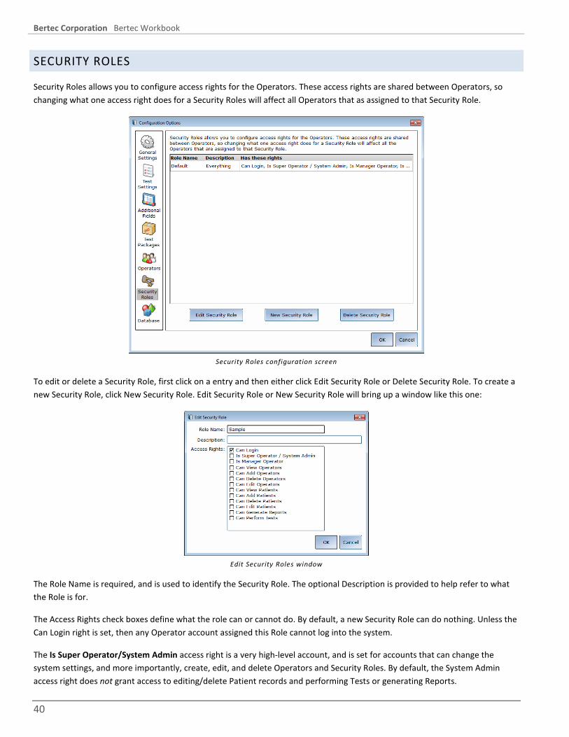
Bertec Corporation Bertec Workbook
40
SECURITY ROLES
Security Roles allows you to configure access rights for the Operators. These access rights are shared between Operators, so changing what one access right does for a Security Roles will affect all Operators that as assigned to that Security Role.
Security Roles configuration screen
To edit or delete a Security Role, first click on a entry and then either click Edit Security Role or Delete Security Role. To create a new Security Role, click New Security Role. Edit Security Role or New Security Role will bring up a window like this one:
Edit Security Roles window
The Role Name is required, and is used to identify the Security Role. The optional Description is provided to help refer to what the Role is for.
The Access Rights check boxes define what the role can or cannot do. By default, a new Security Role can do nothing. Unless the Can Login right is set, then any Operator account assigned this Role cannot log into the system.
The Is Super Operator/System Admin access right is a very high-level account, and is set for accounts that can change the system settings, and more importantly, create, edit, and delete Operators and Security Roles. By default, the System Admin access right does not grant access to editing/delete Patient records and performing Tests or generating Reports.

Bertec Corporation Bertec Workbook
41
The Is Manager Operator access right is similar to the System Admin access right, in that it also has access to the Configuration screen and settings, but cannot add, change, or delete Operators or Security Roles. It also by default does not grant access to the Patient list nor Tests and Reports.
The View/Add/Delete Operators rights may be granted outside of the System Admin access right for Security Roles where you want someone to have that right without having overall System Admin rights.
An Operator without View/Add/Delete Patient rights will have no access to Patients, and by extension, will not be able to use the system at all. We recommend that you give at least View Patients rights as a security role.
Generate Reports access right gives access to the Reports tab, while Perform Tests gives access to the Tests tab.
Once a Security Role has been defined, it can be used by one or more of the Operator accounts. The Role will appear in the Edit Operator's Security Role drop-down list.
DATABASE
The Database Configuration screen page is where you can see the current Database statistics, schedule automatic backups, manually backup and restore the database, and merge another database into the current one. This Configuration Screen can also be directly accessed by the Workbook application menu item titled "Database Maintenance".
Database Maintenance screen
The Tools button lets you check the integrity of the database, and optionally perform an optimization / reorganization of the database. Typically, neither of these functions needs to be done since the database system will automatically adjust itself as needed, based on the usage patterns of the system.
If the Automatic Archive checkbox is set, then the How Frequently, Start Time, and Folder options become available. The How Frequently controls how often the backup is done on the given Start Time. This can be either Daily, Weekly, or Monthly.

Bertec Corporation Bertec Workbook
42
Daily - every N days. For example, if 1 is set, then every day of the week (Monday, Tuesday, etc.) the backup will be perform; if 2 is set, then every 2nd day (Monday, Wednesday, Friday, Sunday, Tuesday, etc.) will be used.
Weekly - every N weeks, on the checked days. For example, if every 1 week on Tuesday and Friday is set, then once a week on those two days it will be backed up; if every 4 weeks on Sunday is set, then the next following Sunday from now and then 4 weeks later the database will be backed up.
Monthly - once a month, on either a specific day N of the month (1 through 31), or a specific first, second, third, fourth, or last given data of the week. For example, if the Day 15 of the month is set, then on the 15th of the month the database will be backed up; if instead the 3rd Friday of the month is set, then on that Friday the database will be backed up.
To back up the database right now, click the Perform Database Archive Now. This will prompt you for the folder to save the archive in, defaulting to the value in the Folder entry box. After the archive is complete, the Workbook system will show you the name of the archive file and give you the option to open the folder so that you may copy the file elsewhere, such as a network share or removable storage. The archive created using the Archive Now button is the same as one done through the scheduled backup.
To restore from or merge with a backed up database from an archive, click the Merge or Restore Database From Archive button. This function will prompt you for the archive file; once you select an archive file, you are given the option to either merge the selected archive into your current database, or use the archive to replace your current database complete. You are also given the option to first back up your current database (by default, selected, and recommended).
Warning! Restoring a database from an archive will completely replace the current database contents. Only perform this action if you have a legitimate reason to do so, such as moving a database from one computer to another, or replacing a corrupted database due to harddrive failure or other issues. This operation cannot be undone! Merging instead is strongly recommended – see the next section for more information.
Database files and database archives are encrypted, and cannot be read or modified by other programs. Do not attempt to modify the database files or database archives, otherwise data loss will occur.
Note: depending on the size of the database, computer speed, and harddrive, creating or restoring an archive can take a very long time. Plan accordingly; it is best to perform a archive operation when there are no scheduled Patients for the rest of the day.
After the database has been archived or restored, you are returned back to the Bertec Workbook interface; if needed, the Patient list will be reloaded.

Bertec Corporation Bertec Workbook
43
DATABASE MERGING
Bertec Workbook includes a powerful feature that allows the operator to combine two or more databases into a single unified database. The merge functionality is part of the Database Restore feature, and is the preferred mode of operation. By default, when the Merge or Restore Database from Archive button is clicked and an archive is select, the Merge Database option is select.
The Merge functionality is useful when you have two or more systems and want to have a system that has copies of the data from both of them. Back up the database on one system, copy it to the other, and Merge the archive file into the current database.
Note: depending on the size of the database and the archive being merged, the Merge operation can take a very long time. It is best to perform a Merge when there are no scheduled Patients for the rest of the day. During the Merge, no testing or patient operations can take place.
Note: the Merge functionality does not push the current database back into the archive file; the archive file is only read for changed or new records, which are then copied into the current Bertec Workbook database. In order to get the current database changes back to the other system, you will need to back up the database and take the archive file to it, and perform the same Merge procedure there.
To use the Merge functions, start Workbook and log into the program. Select the Database Maintenance menu item from the Workbook system icon, and click the Merge or Restore Databases from Archive button. Select the archive file you wish to merge from, and then accept the default Merge option, along with the optional (but suggested) backup first checkbox.
The archive file can be located on your local harddive, a usb “thumb drive” or a network share, but any media that you have the archive file stored on will work.

Bertec Corporation Bertec Workbook
44
QUICK SCREENING The Quick Screening feature in Workbook is provided as a way to use the system in an informal group or ad-hoc setting. When the Operator clicks on the Quick Screening button in the Login screen, the Workbook system will automatically log in the pre-configured Operator and start the pre-configured Quick Screening package.
Note: if Auto-Login is enabled, then the Login screen is bypassed and you cannot get to the Quick Screening button until you click the Log Out button. If the Single User Mode is enabled, then the Log Out button is removed, and Quick Screening will be completely disabled.
The Quick Screening button
Regardless of the selected Package that Quick Screening is configured for, it will always show the following introductory page:
Quick Screening introduction page
This introduction page needs at the very least the year the subject was born and their height - the exact date of their birth is not needed at this point. The year is used to compute the subject's age at the time of the test, so that the built-in normative data can be used. The subject's height is used in the Test protocol as part of a statistical computation. The subject's name is optional, and can be left off until the end of the Quick Screening when the Operator has a option of saving the results.
For the BalanceCheck Screener protocol, the Quick Screening package should be used, which is the same as the Balance Sensory Screen. These packages are pre-defined by the BalanceCheck Screener protocol add-on to perform the following Tests:
• Eyes Open on a Flat Surface • Eyes Closed on a Flat Surface • Eyes Open on a Foam Surface • Eyes Closed on a Foam Surface
The Package that the Quick Screening will use can be configured in the Configuration - General Settings screen, and of course the actual Package contents can be changed to include more or less Tests or Trainings.
When the "Ready to Begin" button is pressed in the Quick Screening Introduction screen, the Workbook system will proceed as a it normally does when performing a test for a patient. If the system has the Auto-Start Test and Auto-Advance Test settings

Bertec Corporation Bertec Workbook
45
turned on, then these will also be in use during Quick Screening. This may not be suitable for some applications of the program, so you may wish to turn these features off in the Configuration - Test Settings screen.
Once a Quick Screen has completed, or the Operator feels that the protocol has completed as far as they want to go, they can elect to either Start Another Quick Test, or Save the results. The Operator can also add notes, email, or print the results just like any other Test.
Quick Screen buttons
The green circle with the arrow looping back is the Start Another Quick Test command. The Operator can either click this or press Control-Q on the keyboard. The program will prompt the Operator to confirm they want to do this. Start Another will discard the test results and go back to the Introduction screen. An Operator would use this button if the Patient doesn't want to keep their results for later, or if the current situation does not call for keeping the data.
The disk icon is the Save Quick Screen Results, and can be invoked by clicking the icon or pressing Control-S on the keyboard. The Workbook system will show the Edit Patient Info screen and pre-fill in the name if the Operator entered it on the Quick Screen Introduction screen. The height will also be pre-filled in. The date of birth will need to be completed, and the SSN value will need to be entered if that option is set in the Configuration screen. Once the Operator clicks Save Changes, a Patient record is created in the database and the Test results are also saved, and the program returns back to the Quick Screening Introduction, ready for the next subject.
Once the Operator has completed with Quick Screening, they will need to click the Exit Quick Screening button that is shown below the Start and Stop buttons, under the list of Tests in the Quick Screening introduction. The log out button does not function in Quick Screening.
Note that while the program is in Quick Screening mode, access to the system menu is curtailed, and only the basic About and Help are available.

Bertec Corporation Bertec Workbook
46
BALANCECHECK SUPPORT STRUCTURE Your system may have been purchased with a BalanceCheck Support Structure hardware frame and harness. This structure, together with the harness and the shoulder straps, is designed to prevent the patient from falling while performing the tests. Two people can easily assemble the BalanceCheck Support Structure.
The Support Structure includes:
• Support structure parts
• Screws to rigidly connect the structure parts
• A tool (hexagonal Allen wrench) to tighten the screws
• Assembly instructions
Open the box containing the Support Structure. Put aside the harness and the foam, and unpack the Support Structure. On a leveled surface, assemble the support structure by following the instructions included in the box.
The support structure is ferromagnetic: be careful if the structure is installed in the same environment as other equipment emitting or sensitive to magnetic fields. Failure to do so can result in system damage, and/or personal injuries.
SUPPORT STRUCTURE HARNESS AND SHOULDER STRAPS
The harness and shoulder steps, together with the support structure, are designed to prevent the patient from falling while performing any of the tests. These include:
• A complete harness - already assembled, ready to be worn
• Two shoulder straps to connect the harness to the support structure
• Four connectors to attach the harness to the shoulder straps and the shoulder straps to the support structure

Bertec Corporation Bertec Workbook
47
ShoulderStrapsHarness
Harness and shoulder straps
HARNESS
The harness is to be worn by the patient throughout all the testing and removed only after all the tests are completed. The harness is a "full-body" model that consists of several permanently attached parts. The parts of the harness are identified below.
female waist snap buckle
back
left shoulder suspender
leg strap
leg rings buckle
shoulder rings
leg loop
waist strap Shoulder suspender buckle
right shoulder suspender
male waist snap buckle
Harness parts identification
The harness might not fit very small or very large body sizes. Given the patient size, decide if the patient can comfortably wear the harness in safely while performing the test protocol. If your patient population is mainly at the extremities of the size range (for instance, most of your patients are children under 12 years of age), contact your Customer Support representative for a customized harness.
For the harness to work properly, make sure that the shoulder rings (the connection points of the harness to the shoulder straps) are always at the top of the patient's shoulders, and symmetrically positioned on each shoulder. Failure to do so can result in personal injuries.

Bertec Corporation Bertec Workbook
48
STRAP LENGTH ADJUSTMENT - SUSPENDER AND WAIST
To increase the length of the strap, hold the buckle firmly with one hand. With the other hand, pull the strap at a 90° angle to the buckle.
To reduce the length of the strap, hold the buckle firmly with one hand. With the other hand, pull the strap from the loose extremity at a 90° angle to the buckle until the desired length is reached.
To reduce the length of the waist strap, have the patient wear the harness, connect the waist strap, and then symmetrically pull the loose ends on both sides of the waist snap buckle until the desired length is achieved.
WAIST STRAP BUCKLE
To buckle the waist strap, hold the male snap part in one handle, and the female part in the other. Insert the male until it snaps into position, which buckles the waist strap. To unbuckle, reverse the procedure.
Always be sure that the waist snap buckle is in the front of the patient, symmetrically positioned between the shoulder suspenders. For the patient's safety, verify that the buckle is fully engaged. Failure to do so can result in personal injuries.
LEG STRAP LENGTH ADJUSTMENT
To increase the length of the strap, hold the leg rings buckle firmly in one hand. With the other hand, push the free end of the strap through the leg rings buckle, making a loop between the two rings. Then pull the other end of the strap until the loop disappears. Repeat this process until the desired length is reached.
To reduce the length of the strap, hold the leg rings buckle firmly in one hand. With the other hand, pull the loose end of the strap until the desired length is reached.
LEG RINGS BUCKLE
To buckle the leg strap, hold the leg rings buckle in one hand. Insert the leg strap through both rings, going from the bottom upwards (υ in diagram). Insert the leg strap through the second ring, going from the top downwards, and making a loop around the first ring (ϖ in diagram). Pull the free end of the leg strap until the loop disappears (ω in diagram).
The leg rings buckle is positioned correctly when pulling the free end of the leg strap reduces the strap length. Pulling the other end of the leg strap will cause the buckle to lock. For patient's safety, verify that the buckle is correctly engaged. Failure to do so can result in personal injuries.

Bertec Corporation Bertec Workbook
49
�
� �
Legs rings buckle diagram
SHOULDER STRAPS
The shoulder straps are necessary to connect the harness worn by the patient to the support structure.
The shoulder straps are 36" (0.914 m) long with two extremity loops and several intermediate loops, to accommodate different patient heights.
The shoulder straps are symmetrical and either end can be connected to the support structure.
Extremity loopConnector
ConnectorExtremity loop
Intermediate loops
Shoulder straps diagram

Bertec Corporation Bertec Workbook
50
To connect the shoulder straps to the harness, clip the shoulder straps into the harness shoulder rings - see the diagram below. Then adjust the length according to the patient's height, leaving some extra length.
One end of each shoulder strap should be connected to the support structure at all times. The opposite end of the strap should be connected to the patient harness before performing any test, and removed after the tests are completed.
The shoulder straps are part of the safety system for preventing the patient from falling during the test protocol. They must be connected both to the patient harness and to the support structure for the safety system to be effective, and therefore prevent injury.
�
��
Should straps to support frame connection diagram
SELECTING THE CORRECT SHOULD STRAP LENGTH
To select the correct strap length, have the patient stand on to of the platform, with the straps hanging from the support structure. Select the first intermediate loop that is just below the patient's shoulder height. Remove the connecter from the free extremity loop, and position it in the chosen intermediate loop. Connect this to the harness should ring. Repeat for the other shoulder strap. The length of both shoulder straps must be the same length in order to ensure symmetrical support.
Have the patient lean forward and to the left and right to verify that the shoulder straps are not impeding movement, and that there is not too much slack. If necessary change the intermediate loop where the connector is positioned.
The shoulder straps might not be long enough to be connected to very small patients. If this is the case, contact your Customer Support representative for customized straps.
HELPING THE PATIENT GET INTO THE HARNESS
• Pick-up the harness and verify that all straps are long enough to comfortably fit the patient.

Bertec Corporation Bertec Workbook
51
• Holding the harness by the shoulder suspenders, pull them over the patient's shoulders, so that the back of the harness is on the back of the patient.
• Position the waist strap by connecting the male right waist snap buckle to the female left waist snap buckle.
• Insert the leg strap in the leg loop between the patient's legs (υ in the diagram below), pull it forward (ϖ in the diagram) and tighten it using the leg rings buckle (ω in the diagram).
• Adjust the length of each part of the harness. The straps should fit perfectly against the patient's body, but not too tightly.
• For each shoulder, check that one of the shoulder rings is at the top of the patient's shoulder, or if it is movable, slide it in such a position.
Before After
�
�
�
Leg strap positioning diagram
Before proceeding with any testing, be sure that the patient is properly wearing the harness. Failure to do so may result in patient injury.
HELPING THE PATIENT REMOVE THE HARNESS
• Disconnect the shoulder straps from the harness shoulder rings, by reversing the steps taken to connect them.
• Avoiding the platform connector, help the patient step off the BalanceCheck platform.
• Help the patient remove the harness by reversing the steps taken to put it on.
• Instruct the patient to put his or her shoes back on.

Bertec Corporation Bertec Workbook
52
FORCE PLATE PLATFORM The Bertec force plate platform contains the sensing part of the system. The platform is ready to be used. No assembly is required. It is only necessary to position the platform correctly and connect it to the computer.
• Open box containing the force plate platform and unpack it.
• Pick up the platform cable; identify the platform connector as the square USB connector.
• Plug in the USB cable provided with the system to the computer.
• Using the adjustable foot, level the platform so it does not rock on the floor.
• Connect the USB cable to the platform cable (plug it into the small black box).
• Plug in the USB cable to the force plate. This step should be performed after installing the software (please refer to Workbook System Installation).
The platform cable connecting the platform to your computer, as well as all other cables, may cause someone to trip. It is recommended that these cables be routed or use masking tape to hold the cables to the floor to prevent tripping.
The force plate platform is NOT WATERPROOF. It is FOR INDOOR USE ONLY. Using the platform outdoors or exposing it to water can result in system damage.
Do not step on the platform connector. Doing so will damage the platform.
The digital Balance Platform that comes with your system is a self-calibrating device. Therefore, no calibration is needed before the test. If you determine that the platform is reading the incorrect weight or values, have the patient step off the platform and use the program menu icon on the top right of the application and select Zero Plate Load. You do not need to exit the current test or training.
PLATFORM SPECIFICS
2 ¼" (0.055 m)
20" (0.508 m)
Adjustable foot
20" (0.508 m)
Platform diagram with false-color representation
The platform is designed for a maximum load of 500 lbs. (220 kg).
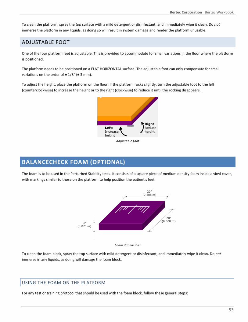
Bertec Corporation Bertec Workbook
53
To clean the platform, spray the top surface with a mild detergent or disinfectant, and immediately wipe it clean. Do not immerse the platform in any liquids, as doing so will result in system damage and render the platform unusable.
ADJUSTABLE FOOT
One of the four platform feet is adjustable. This is provided to accommodate for small variations in the floor where the platform is positioned.
The platform needs to be positioned on a FLAT HORIZONTAL surface. The adjustable foot can only compensate for small variations on the order of ± 1/8" (± 3 mm).
To adjust the height, place the platform on the floor. If the platform rocks slightly, turn the adjustable foot to the left (counterclockwise) to increase the height or to the right (clockwise) to reduce it until the rocking disappears.
Right:Reduceheight
Left:Increaseheight
Adjustable foot
BALANCECHECK FOAM (OPTIONAL) The foam is to be used in the Perturbed Stability tests. It consists of a square piece of medium density foam inside a vinyl cover, with markings similar to those on the platform to help position the patient's feet.
3" (0.075 m)
20" (0.508 m)
20" (0.508 m)
Foam dimensions
To clean the foam block, spray the top surface with mild detergent or disinfectant, and immediately wipe it clean. Do not immerse in any liquids, as doing will damage the foam block.
USING THE FOAM ON THE PLATFORM
For any test or training protocol that should be used with the foam block, follow these general steps:

Bertec Corporation Bertec Workbook
54
• Have the patient step off the plate, and select the appropriate test protocol and options, if applicable.
• Place the foam on top of the Balance Plate, with the reference lines facing up.
Placing the foam on platform
• Wait about 15 seconds to make sure that the system calibrates itself to compensate for the weight of the foam. The weight display should re-zero out. If it does not, then use the Workbook program menu icon in the top-right of the program, and select Zero Plate Load.
• Avoiding the platform connector, help the patient step onto the force plate platform and position his/her feet to form a square on the middle of the platform, using the lines as a reference (for more information, please refer to Positioning Patient's Feet).
• Connect the shoulder straps to the harness shoulder rings. Adjust the length according to the patient height, leaving some extra length. The shoulder straps should not pull the patient, nor impair movement, but just prevent the patient from falling (for more information, please refer to Harness and Shoulder Straps).
• Have the patient stand still in a comfortable position, with weight centered, with their eyes either open or closed depending on the test and options, and arms to the sides. The patient should avoid any unnecessary movement, such as talking, gesturing, or turning, as reminded by the instructions on the screen.
• Click the “Start” button to start the test or training. Depending on the protocol, the test will either stop automatically or require the operator to click the Complete button.
When the progress bar disappears, the test will either auto advance to the next test or you may click on the next test you wish to perform.

Bertec Corporation Bertec Workbook
55
POSITIONING THE PATIENT’S FEET There are markings on the top of the platform to help with the positioning of the patient’s feet, as shown in the following diagram:
Middle lineMalleolus line
Side lines
Top positioning guidelines on the platform
• To position the patient’s feet, use the following steps to help:
• The medial malleolus of both feet should be aligned with the malleolus line on the platform.
• The feet should be symmetric around the midline and the outside borders should form an imaginary square.
• The angular alignment of the feet should be such that the patient does not feel uncomfortable (patient should not be forced to position the feet parallel to each other if they cannot).
Position of the feet on the platform

Bertec Corporation Bertec Workbook
56
TEST PROTOCOL SAFETY GUIDELINES & NOTES
Special note: the Calorics Session of Video Electronystagmography (VNG) might make the patient dizzy and unstable. Therefore, it is highly recommended that BalanceCheck sessions be performed before VNG or on a separate day.
• The force plate platform requires a 2-minute warm up period every time it is connected to the computer (the computer should be on). This is required for electronics stabilization and optimal performance. Failure to do so can compromise the accuracy of the results obtained with the system.
• When scheduling the patient to be tested with the system, suggest to your patients that a gym outfit and easy to remove shoes should be worn. (Due to possible effects of footwear, the protocol requires the patient to perform all tests either barefoot or wearing socks.)
• The level of difficulty in each test may be changed by varying different session parameters; not all tests or trainings will have options, however. Some of the test or training parameters are normalized to other data; please consult the appropriate protocol documentation for information.
• The tests contained in the protocols may not be applicable or appropriate for all patients. Patient safety is the responsibility of the person administering the tests, and the protocols should be performed according to the specific patient's abilities.
• Before proceeding with any testing, be sure that the patient is properly wearing the harness. Failure to do so may result in patient injury.
• Patients performing the tests or trainings may be unsteady, could become unsteady, or could move outside their normal range of balance. The safety harness is part of the safety system for preventing the patient from falling during the test protocol. It is to be worn by the patient before starting any tests, and removed only after all the tests are completed.
• For the patient's safety, verify that the patient correctly wears the harness.
• Since the platform and the support structure are positioned above the floor level, always assist the patient in stepping onto or off the platform and in assuming the correct position to perform the tests.
• One end of each shoulder strap should be connected to the support structure at all times. The opposite end of the strap should be connected to the patient harness before performing any test, and removed after the tests are completed. Failure to do so may result in patient injury.
• The length of both shoulder straps must be the same to ensure symmetrical support.
• Follow standard sanitary procedures between patients.
• The tests can be performed in any order. However, it is suggested to perform the tests in the given order as per the documentation for those protocols. Note: If something goes wrong during one of the tests, it is possible to redo that test. See the Workbook program documentation for more information.
• While the patient is performing the test, note anything that can influence the results of the test and if necessary redo the test. When analyzing the results in the reports, it is possible to add all the test notes to the results for easy

Bertec Corporation Bertec Workbook
57
comparison between different test sessions. Also keep track of how the patient feels in general and especially while performing the test.
• To monitor the patient's ability to maintain balance it is good practice to print the Test Report after every test session. Comparing the results from different test sessions, it is possible to evaluate the patient's ability to maintain balance over time.
END OF TEST REPORT
When the tests or trainings complete, the End Of Test Report item will show the report from the tests that were performed. You may either print this out using the printer icon button, or email it using the email icon button.

Bertec Corporation Bertec Workbook
58
BALANCECHECK SCREENER The BalanceCheck Screener series of tests have been designed to assess the patient's ability to maintain balance while standing. In the full version of the system, three aspects can be tested: the ability to maintain balance on a hard level surface (Normal Stability, Firm Surface), on a soft surface (Perturbed Stability, Foam Surface), and the maximum movement in the sagittal and lateral directions without losing balance (Limits of Stability).
The time required to perform all the available tests is about 10-15 minutes.
Since the patient may lose balance and fall, the tests must be performed only if the patient is wearing the harness and the harness is properly connected to the support structure (full version only). Proper use of the support structure and harness is required to help prevent patient fall and injuries during Limits of Stability testing.
When scheduling the patient to be tested with the BalanceCheck Screener system, suggest to the patient that a gym outfit and easy-to-remove shoes should be worn. Due to possible effects of footwear, the protocol requires the patient to perform all tests either barefoot or wearing socks.
The BalanceCheck Screener system is NOT WATERPROOF and is FOR INDOOR USE ONLY. Using the BalanceCheck Screener system outdoors or exposing it to water can result in system damage.
Your reseller may have requested modifications and enhancements to the Bertec Workbook program and its components. These changes would be documented by your reseller. If you have any questions about the differences between the documentation herein and your reseller's product, please contact your reseller first.
The BalanceCheck Screener protocols includes four Standing Stability tests and a Limits test:
• Eyes Open on a Firm Surface – Normal Stability
• Eyes Closed on a Firm Surface – Normal Stability
• Eyes Open on a Foam Surface – Perturbed Stability
• Eyes Closed on a Foam Surface – Perturbed Stability
• Limits of Stability
All four of the Standing Stability tests have the same interface and single report for the Session - all four test results are combined into this single report. Limits of Stability has its own separate report.
NORMAL STABILITY
The Normal Stability tests requires that the patient stands still on the platform in a comfortable position with the feet symmetrically apart. These are the Eyes Open or Eyes Closed on a Firm Surface tests.
The ability to maintain balance is evaluated in two conditions: with the patient's eyes open, and with eyes closed. These results are compared with standard results obtained for a person of the same height as the patient.

Bertec Corporation Bertec Workbook
59
PERTURBED STABILITY
The Perturbed Stability tests requires that the patient stands still on a soft foam surface. Having a compressible cushion (the foam) placed between the patient's feet and the platform perturbs the equilibrium. These are the Eyes Open or Eyes Closed on a Foam Surface tests.
The ability to maintain balance is again evaluated in two conditions: with the patient's eyes open, and with eyes closed. These results are compared with standard results obtained for a person of the same height as the patient.
LIMITS OF STABILITY
The Limits of Stability is evaluated through tests that require the patient to stand on the platform in a comfortable position with the feet symmetrically apart and to lean in four different directions.
The Limits of Stability is evaluated in the sagittal and lateral directions: the patient is asked to lean forward, backward, leftward, and rightward as far as possible without losing balance.
The Limits of Stability is compared with standard results obtained for a person of the same height as the patient. An additional comparison between the patient's Limits of Stability and the patient's Normal Stability - Eyes Open test (if performed) is included in the Full Report.
STANDING STABILITY TESTS
These tests evaluate the patient’s standing stability, and consist of four individual tests: Eyes Open on a Firm Surface, Eyes Closed on a Firm Surface, Eyes Open on a Foam Surface, and Eyes Closed on a Foam Surface. All four tests are used in the same manner, and have the same user interface. As each test is selected, instructions are shown on the screen, along with a Center of Pressure display, progress bar, and a check box to indicate if the patient lost balance:
Standing Stability test interface
To start the tests, follow the instructions on the screen and click the Start/Restart Tests from Top, and click the Start button to perform the test (if you have the Workbook program configured to auto-start when the patient is still, the test will automatically start and finish). You may click on any test to go it, and if auto-advance is turned on, then the next test will be automatically selected as the current one completes.
The Weight display will show the patient's weight, unless the Show Weight checkbox is cleared, then it will show nothing. The grey box above the Weight is the Center of Pressure display and shows where patient's center of pressure or gravity is at. The

Bertec Corporation Bertec Workbook
60
weight display is controlled by the Configuration settings. If, at any time, you wish to see the Patient's weight, you can click and hold the Show Weight button.
The general procedure for the Standing Stability series of tests are:
• Instruct the patient to remove his or her shoes.
• Avoiding the platform connector, help the patient step onto the BalanceCheck platform and position his/her feet to form a square on the middle of the platform, using the lines as a reference (for more information, please refer to Positioning Patient's Feet).
• Connect the shoulder straps to the harness shoulder rings. Adjust the length according to the patient height, leaving some extra length. The shoulder straps should not pull the patient, nor impair movement, but just prevent the patient from falling (for more information, please refer to Harness and Shoulder Straps).
• Have the patient stand still in a comfortable position, with weight centered, with their eyes either open or closed depending on the test, and arms to the sides. The patient should avoid any unnecessary movement, such as talking, gesturing, or turning, as reminded by the instructions on the screen.
• Click the “Start” button to start the test acquisition, which lasts for 10 seconds. A progress bar will appear while the system is collecting data.
• When the progress bar disappears, the test will either auto advance to the next test or you may click on the next test you wish to perform.
LIMITS OF STABILITY
The Limits of Stability test determines how far the patient can lean in four directions without loosing balance. The operation is similar to the Standing Stability tests, however, the test is not timed and the operator must click the Completed button. When the test is selected, instructions are shown on the screen, along with a Center of Pressure display, progress bar, and a check box to indicate if the patient lost balance:
Limits of Stability test interface
To start the test, follow the instructions on the screen and click the Start/Restart Tests from Top, and click the Start button to perform the test (if you have the Workbook program configured to auto-start when the patient is still, the test will automatically start and finish).

Bertec Corporation Bertec Workbook
61
The Weight display will show the patient's weight, unless the Show Weight checkbox is cleared, then it will show nothing. The grey box above the Weight is the Center of Pressure display and shows where patient's center of pressure or gravity is at.
The general procedure for the test is:
• Avoiding the platform connector, help the patient step onto the force plate platform and position his/her feet to form a square on the middle of the platform, using the lines as a reference (for more information, please refer to Positioning Patient's Feet).
• Connect the shoulder straps to the harness shoulder rings. Adjust the length according to the patient height, leaving some extra length. The shoulder straps should not pull the patient, nor impair movement, but just prevent the patient from falling (for more information, please refer to Harness and Shoulder Straps).
• Have the patient stand still in a comfortable position, with weight centered, with their eyes open, and arms to the sides.
• Click the “Start” button to start the test acquisition, which lasts for 10 seconds. A progress bar will appear while the system is collecting data.
• Have the patient lean as far as possible in the forward, backward, right and left directions (the order of directions is not important) without losing balance or moving the feet, with eyes open, and arms to the sides. The patient should avoid any unnecessary movement, such as talking, gesturing, or turning, as reminded by the instructions on the screen. This test measures the ability to lean: when the limit in a certain direction is reached, the patient does not have to hold such a position, but can return to the starting position. When the patient is finished leaning into all four directions then click the Completed button to finish the test. The Stop button performs a different function and should only be pressed to abort the test.
• After the test completes, disconnect the straps from the harness and help the patient step off the platform.
• Since the maximum time limit for Limits of Stability test is 5 minutes, do not hurry the patient to start moving. There is plenty of time for the patient to lean in every direction before finishing the test.
INTERPRETING THE RESULTS
The Standing Stability report show the results for all four of the Standing Stability tests - Eyes Open on Firm Surface, Eyes Closed on Firm Surface, Eyes Open on Foam Surface, Eyes Closed on Foam Surface - on the same page. If a test was not performed, then that part of the report is left blank. Each of the tests has a graph, a Stability Score, and the results.
Eyes Open on Firm Surface - this test gives an indication of the patient's ability to maintain balance in normal conditions, i.e., on a hard, level surface, with eyes open. A low Stability Score can indicate that the patient has problems in maintaining balance.
Eyes Closed on Firm Surface - this test gives an indication of the patient's ability to maintain balance in normal conditions, i.e., on a hard, level surface, with eyes closed. A low Stability Score can indicate that the patient finds it difficult to maintain balance without visual references.
Eyes Open on Foam Surface - this test gives an indication of the patient's ability to maintain balance in perturbed conditions, i.e., on a soft, unstable or uneven surface, with eyes open. A low Stability Score can indicate that the patient has problems in maintaining balance when the support is not a hard, level surface.

Bertec Corporation Bertec Workbook
62
Eyes Closed on Foam Surface - this test gives an indication of the patient's ability to maintain balance in perturbed conditions, i.e., on a soft, unstable or uneven surface, with eyes closed. A low Stability Score can indicate that the patient has problems in maintaining balance when the support is not a hard, level surface without visual references.
Each graph shows a statistical representation of the Center of Pressure: the 95% confidence ellipse, i.e., the ellipse that contains 95% of the Center of Pressure points during the specific test. From each graph it is possible to assess visually how much the patient moved during the test - the smaller the ellipse the better. In addition, it also gives information about which direction the patient moved. The major axis of the ellipse is aligned with the primary direction of movement. The aspect ratio of the ellipse (ratio between minor and major axes) gives an indication of the directionality of the movement. A narrow ellipse indicates that the movement was primarily along one direction, whereas a more rounded ellipse indicates that the movement did not have a well defined primary direction.
The numerical values for the results are all referred to the statistical analysis conventionally done on the Center of Pressure path: the 95% confidence ellipse. For each test (Eyes Open on a Firm Surface, Eyes Closed on a Firm Surface, Eyes Open on a Foam Surface, Eyes Closed on a Foam Surface) the parameters considered are:
Anterior-Posterior Sway Range is the length of the projection of the ellipse on the vertical axis. It is an indication of the magnitude of the movement in the sagittal plane; the smaller the value the better.
Anterior-Posterior Sway Range
Anterior-Posterior Sway Range
Lateral Sway Range is the length of the projection of the ellipse on the horizontal axis. It is an indication of the magnitude of the movement in the lateral plane; the smaller the value the better.
Lateral Sway Range
Lateral Sway Range
Direction of Max Instability is the amount of counterclockwise rotation necessary to bring the horizontal axis to the major semi-axis of the ellipse, expressed in degrees. It is an indication of the primary direction of movement. It can have any value. For example, 0° indicates that the direction of maximum instability is to the forward, whereas +90° indicates that the direction of maximum instability is to the right (by convention positive angles are to the right).

Bertec Corporation Bertec Workbook
63
Direction ofMax Instability
Direction of Max Instability
Stability Score is a score of the patient's ability to maintain balance during the test. It is calculated by the BalanceCheck software as
%S
AS
dardtans
maxdardtans −
where maxA is the major semi-axis of the 95% confidence ellipse and dardtansS represents the Standard Limits of Stability, calculated as
º25.6sin55.0 HS dardtans =
where H is the patient's height (Bioastronautics Data Book, NASA, 1962).
The Stability Score can have any value between 0% and 100%; the larger the value the better. 100% indicates that the patient was able to maintain perfect stillness. 0% indicates that the patient used all the Standard Limits of Stability during the test, and, theoretically, the patient was unable to maintain any balance during the test.
0% 100%
StabilityScore
Unableto stand
Perfectlystill
Stability Score
The line below the Stability Score displays the Normative Values for Age-Matched Average Score of healthy persons. The two lines below the normative values display the lower bounds for 2 and 3 Standard Deviations (SD) from the Age-Matched Average Score. The Stability Scores of the patient is highlighted with the same color matching normative values indicated by the color bars next to the Average Score and its standard deviations. In other words, green for Stability Scores above (Average Score – 2*SD), yellow between (Average Score – 2*SD) and (Average Score – 3*SD), and red for less than (Average Score – 3*SD).
The Age-Matched Average Score information is provided to facilitate the comparison of a patient’s Stability Scores with the normative values, but does not constitute a clinical interpretation. Such an interpretation can only be made by a qualified person.
The Limits of Stability report is a single test result. If there is a corresponding Eyes Open on a Firm Surface, then the report will also report it to contrast with the Limits of Stability results. The report gives an indication of the limits of the patient’s ability to

Bertec Corporation Bertec Workbook
64
maintain balance compared to a Standard Limits of Stability. A low Limits of Stability score can indicate that the patient is less stable than age-matched peers and therefore more likely to fall.
Limits of Stability graph
The Actual Limits of Stability graph shows a circle (red) representing the Standard Limits of Stability dardtansS , calculated as
º25.6sin55.0 HS dardtans =
where H is the patient's height (Bioastronautics Data Book, NASA, 1962). This assumes that the standard stability is the same in all directions of movement.
Also shown is the ellipse (blue) that best fits the maximum excursions in the four different directions (forward, backward, left, and right). Supposing that the stability region can be seen as a superposition of the max excursions in the four directions, this ellipse infers the actual area of stability of this patient.
LoSForward
LoSBackward
LoSRight LoSLeft
LoSEllipse
StandardLoS
Limits of Stability ellipse
The comparison between the Standard Limits of Stability circle and the Limits of Stability ellipse represents how much of the Standard Limits of Stability area was used by the patient: the larger the ellipse the better. The ellipse might be smaller than (not all the Standard Limits of Stability is used) equal to, or larger than (the Limits of Stability region of the patient is better than the Standard Limits of Stability) the circle.
Limit of Stability smaller than normal
Limit of Stability larger than normal laterally
and smaller sagittally Limit of Stability
larger than normal
Examples of Limits of Stability ellipse vs. Standard Limits of Stability circle

Bertec Corporation Bertec Workbook
65
The center of the ellipse might not be aligned with the center of the circle. This means that the Limits of Stability of the patient is not symmetrical. Furthermore, there might be a predominant direction of stability, represented by the direction of the maximum distance of the ellipse from the center of the circle.
Predominant direction of stability
Primary direction of movement
The Actual Limits of Stability numerical values are given as:
• LoS (Limits of Stability) is calculated by the BalanceCheck software as the maximum excursion of the Center of Pressure path in the specified direction of the test (e.g., in the Forward Limits of Stability is the maximum excursion in the forward direction). The measurement units are the same as the graph.
• LoS (Limits of Stability) Score represents how the patient's Limits of Stability compares with the Standard Limits of Stability. It is calculated, for the four directions of forward, backward, leftward, and rightward movements, as
S
Sstandard
max % where Smax is the maximum excursion of the Center of Pressure path in the specified direction of the test
(e.g., in the Forward Limits of Stability Smax is the maximum excursion in the forward direction) and Sstandard represents the Standard Limits of Stability, calculated as S Hstandard = °0 55 6 25. sin . where H is the patient's height (Bioastronautics Data Book, NASA, 1962).
The LoS Score can have any value; the larger the value, the better. 100% indicates that the patient's Limits of Stability in that particular direction is the same as the Standard Limits of Stability. 0% indicates that the patient was unable to lean in that particular direction (although it might be a sign of an incorrectly performed test). A value less than 100% indicates that the patient's Limits of Stability is less than the Standard Limits of Stability, and, therefore, the patient has a reduced ability to lean without losing balance or using some additional form of support. A value greater than 100% indicates that the patient's Limits of Stability is greater than the Standard Limits of Stability, and, therefore, the patient has a greater ability to lean.
0% 100%
LoSScore
Unableto lean
Normalabilityto lean
>100%Ability to leanbetter than
normal Limits of Stability Score
The LoS vs. Normal Stability - Eyes Open graph shows the comparison between the 95% confidence ellipse obtained during the Normal Stability - Eyes Open test (green), and the ellipse that represent the patient's Limits of Stability (blue).
The comparison between the two ellipses represents how much of the patient's Limits of Stability was used during the Normal Stability: Eyes Open test. The smaller the Normal Stability - Eyes Open ellipse compared to the Limits of Stability ellipse the better. The Normal Stability: Eyes Open ellipse might be smaller than (not all the Limits of Stability was used during the test) equal to, or larger than (the patient actually exceeded the Limits of Stability and most probably lost balance) the Limits of Stability ellipse.
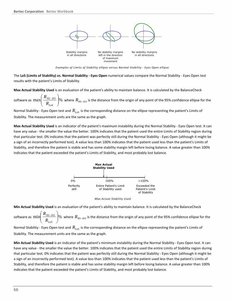
Bertec Corporation Bertec Workbook
66
Stability margins in all directions
No stability margins left in the direction
of maximum movement
No stability margins in all directions
Examples of Limits of Stability ellipse versus Normal Stability - Eyes Open ell ipse.
The LoS (Limits of Stability) vs. Normal Stability - Eyes Open numerical values compare the Normal Stability - Eyes Open test results with the patient's Limits of Stability.
Max Actual Stability Used is an evaluation of the patient's ability to maintain balance. It is calculated by the BalanceCheck
software as %max
−
LoS
EONS
R
R where RNS EO− is the distance from the origin of any point of the 95% confidence ellipse for the
Normal Stability - Eyes Open test and RLoS is the corresponding distance on the ellipse representing the patient's Limits of Stability. The measurement units are the same as the graph.
Max Actual Stability Used is an indicator of the patient's maximum instability during the Normal Stability - Eyes Open test. It can have any value - the smaller the value the better. 100% indicates that the patient used the entire Limits of Stability region during that particular test. 0% indicates that the patient was perfectly still during the Normal Stability - Eyes Open (although it might be a sign of an incorrectly performed test). A value less than 100% indicates that the patient used less than the patient's Limits of Stability, and therefore the patient is stable and has some stability margin left before losing balance. A value greater than 100% indicates that the patient exceeded the patient's Limits of Stability, and most probably lost balance.
0% 100%
Max ActualStability Used
Perfectlystill
Entire Patient's Limitof Stability used
>100%Exceeded thePatient's Limit
of Stability Max Actual Stability Used
Min Actual Stability Used is an evaluation of the patient's ability to maintain balance. It is calculated by the BalanceCheck
software as %min
−
LoS
EONS
R
R where RNS EO− is the distance from the origin of any point of the 95% confidence ellipse for the
Normal Stability - Eyes Open test and RLoS is the corresponding distance on the ellipse representing the patient's Limits of Stability. The measurement units are the same as the graph.
Min Actual Stability Used is an indicator of the patient's minimum instability during the Normal Stability - Eyes Open test. It can have any value - the smaller the value the better. 100% indicates that the patient used the entire Limits of Stability region during that particular test. 0% indicates that the patient was perfectly still during the Normal Stability - Eyes Open (although it might be a sign of an incorrectly performed test). A value less than 100% indicates that the patient used less than the patient's Limits of Stability, and therefore the patient is stable and has some stability margin left before losing balance. A value greater than 100% indicates that the patient exceeded the patient's Limits of Stability, and most probably lost balance.
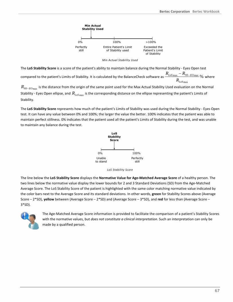
Bertec Corporation Bertec Workbook
67
0% 100%
Min ActualStability Used
Perfectlystill
Entire Patient's Limitof Stability used
>100%Exceeded thePatient's Limit
of Stability Min Actual Stability Used
The LoS Stability Score is a score of the patient's ability to maintain balance during the Normal Stability - Eyes Open test compared to the patient's Limits of Stability. It is calculated by the BalanceCheck software as R R
RLoS NS EO
LoS
max max
max
%−
− where
RNS EOmax− is the distance from the origin of the same point used for the Max Actual Stability Used evaluation on the Normal
Stability - Eyes Open ellipse, and RLoS max is the corresponding distance on the ellipse representing the patient's Limits of Stability.
The LoS Stability Score represents how much of the patient's Limits of Stability was used during the Normal Stability - Eyes Open test. It can have any value between 0% and 100%; the larger the value the better. 100% indicates that the patient was able to maintain perfect stillness. 0% indicates that the patient used all the patient's Limits of Stability during the test, and was unable to maintain any balance during the test.
0% 100%
LoSStabilityScore
Unableto stand
Perfectlystill
LoS Stability Score
The line below the LoS Stability Score displays the Normative Value for Age-Matched Average Score of a healthy person. The two lines below the normative value display the lower bounds for 2 and 3 Standard Deviations (SD) from the Age-Matched Average Score. The LoS Stability Score of the patient is highlighted with the same color matching normative value indicated by the color bars next to the Average Score and its standard deviations. In other words, green for Stability Scores above (Average Score – 2*SD), yellow between (Average Score – 2*SD) and (Average Score – 3*SD), and red for less than (Average Score – 3*SD).
The Age-Matched Average Score information is provided to facilitate the comparison of a patient’s Stability Scores with the normative values, but does not constitute a clinical interpretation. Such an interpretation can only be made by a qualified person.

Bertec Corporation Bertec Workbook
68
Normative Data
The Normative Data values that BalanceCheck Screener uses for calculations is provided here. This table is from Girardi et al.: Fall Risks in Elderly Patient, The Laryngoscope, issue #111, September 2001, pages 1528 through 1532. A copy of this article is available on our web site at www.bertec.com.
AGE (years) NSEO NSEC PSEO PSEC LoS 0-19 92.4 ± 0.53 90.4 ± 0.63 88.2 ± 0.74 79.0 ± 1.32 87.8 ± 1.31 20-29 93.6 ± 0.50 92.2 ± 0.60 89.6 ± 0.70 81.6 ± 1.25 88.4 ± 1.24 30-39 92.5 ± 0.56 91.6 ± 0.68 87.6 ± 0.80 78.2 ± 1.46 87.2 ± 1.41 40-49 93.4 ± 0.55 91.9 ± 0.66 88.3 ± 0.78 79.5 ± 1.38 88.6 ± 1.37 50-59 91.9 ± 0.35 91.0 ± 0.58 86.3 ± 0.68 76.5 ± 1.21 85.0 ± 1.20 60-69 91.7 ± 0.35 90.0 ± 0.43 85.4 ± 0.50 75.2 ± 0.89 83.5 ± 0.88 70-79 92.0 ± 0.33 90.3 ± 0.40 83.4 ± 0.47 71.3 ± 0.84 82.1 ± 0.83 80-89 92.3 ± 0.80 91.1 ± 0.96 77.7 ± 1.13 64.8 ± 2.00 80.9 ±1.98
Age Matched Normative Data for BalanceCheck Stability Scores (Average ± SD)
NSEO : Normal Stability, Eyes Open
NSEC : Normal Stability, Eyes Closed
PSEO : Perturbed Stability, Eyes Open
PSEC : Perturbed Stability, Eyes Closed
LoS : Limits of Stability

Bertec Corporation Bertec Workbook
69
BALANCECHECK TRAINER The BalanceCheck Trainer series of training protocols have been designed to work with both the Operator and the Patient for balance adjustment training. These protocols are a combination of support surfaces, stance conditions, and visual feedback on the screen as the Patient controls their Center of Gravity. The BalanceCheck Trainer consists of several training protocols: Explore Base of Support Training (both Accuracy and Speed), Static Training, Limits of Stability Training, and Weight Shift Training. These Training protocols can be adjusted by the Operator to either increase or decrease the difficulty and challenge. We recommend using the Training protocols after you first conduct an assessment using the BalanceCheck Screener software.
The time required to perform one or all of the Training protocols will vary from patient to patient.
Even the simplest training protocols featured in this system can be a real challenge to the stability of the patients. The Hand Rail structure provided with the system is NOT designed to prevent the patient from falling. Therefore, the clinician conducting BalanceCheck Training should always be on alert and attentive towards the patient as they may easily loose balance and fall.
When scheduling the patient to be tested with the BalanceCheck Trainer system, suggest to the patient that a gym outfit and easy-to-remove shoes should be worn. Due to possible effects of footwear, the protocol requires the patient to perform all tests either barefoot or wearing socks.
The BalanceCheck Screener system is NOT WATERPROOF and is FOR INDOOR USE ONLY. Using the BalanceCheck Screener system outdoors or exposing it to water can result in system damage.
Your reseller may have requested modifications and enhancements to the Bertec Workbook program and its components. These changes would be documented by your reseller. If you have any questions about the differences between the documentation herein and your reseller's product, please contact your reseller first.
The BalanceCheck Trainer protocols includes:
• Static Training
• Weight Shift Training
• Explore Base of Support - Accuracy
• Explore Base of Support - Speed
• Limits of Stability Training
Each of the Training protocols has their own separate interface and report, and the results are shown the Patient Timeline. Refer to the Bertec Workbook user manual for more information about the Patient Timeline.
Training protocols can be performed in any order.

Bertec Corporation Bertec Workbook
70
STATIC TRAINING
The Static Balance Training protocol is designed to train the patient to control the Center of Gravity of the body at different static postures such as standing on one foot or both feet and on different surfaces such as rigid or compliant. The patient tries to keep the Center of Gravity in a specific area, for which the position and size can be changed by the clinician. The length of the time period for training is also adjustable.
Static Training interface
To start the training, follow the instructions on the screen and click the Start/Restart Tests from Top, and click the Start button to perform the training (if you have the Workbook program configured to auto-start when the patient is still, the test will automatically start).
The green Weight display in the middle of the black field will show the patient's weight, unless the Show Weight program option is cleared, then it will show nothing. The black field is where the Center of Gravity is displayed, along with the patient's target box.
The Complete Test and Stop Test buttons are duplicated from the same buttons on the left side of the screen.
By default, all Training protocols will maximize to take up the whole screen, unless the Allow Test to go into Full Screen option in the program configuration is cleared. If you wish to get out of full screen, or to toggle back and forth, press the F12 function key.
SELECTING TRAINING PARAMETERS
The following parameters can be adjusted to vary the intensity and nature of Static Training (see above picture):
Stance: This parameter is used to select between unilateral and bilateral stance options. Available alternatives are: Both Feet, Left Foot, and Right Foot.
Surface: Depending on the surface conditions of the Balance Platform two options are available: Rigid Surface and Compliant Surface. Compliant Surface alternative is selected if training is done on the compliant balance board.
Target Size: The target area is a rectangle for which the size is selected by the clinician.

Bertec Corporation Bertec Workbook
71
Target Positioning: The target position parameter determines how much the center of the target area, whose size is determined by Target Size, will be offset from the neutral standing position of the patient.
Goal Time: The time parameter select by the clinician determines the length of the time interval for which the patient is required to keep the Center of Gravity in the target area.
POSITIONING THE COMPLIANT BALANCE BOARD
The Perturbed Balance Surface is provided so that the patient can be trained with inaccurate proprioceptive input from the ankle joints. This surface should be positioned such that its edges are aligned with the edges of the Balance Platform.
Compliant Balance Board on Balance Platform
POSITIONING THE FEET
Following the guidelines for feet positioning is crucial for a successful training. There are white vinyl markings on the Balance Platform (or a crosshair on the Perturbed Balance Surface) to help with positioning patient’s feet. Using these lines as a guide, the feet should be positioned as follows:
If training is to be performed on two feet:
• The medial malleolus of both feet should be aligned with the malleolus line on the platform or balance board.
• The feet should be symmetric around the midline and the outside borders should form an imaginary square.
• The angular alignment of the feet should be such that the patient does not feel uncomfortable (patient should not be forced to position the feet parallel to each other).
If training is to be performed on one foot:
• The medial malleolus of the foot in question should be aligned with the malleolus line on the platform.
• The target foot should be placed such that the centerline mark on the Balance Platform should coincide with the long axis of the foot (approximately passing through the second toe and mid point of the heel).

Bertec Corporation Bertec Workbook
72
• The other foot is next to the stance foot, and it is to be lifted 1-2 inches from the support surface
It is strongly suggested that training on one foot should be performed on the firm Balance Platform surface only without the Balance Board. Trying to balance the body on one foot on the Balance Board might be dangerous even for a healthy person. THE HANDRAIL SYSTEM ALONE IS NOT DESIGNED TO PREVENT THE PATIENT FROM FALLING. IT IS ONLY AN ASSISTIVE DEVICE TO IMPROVE THE PATIENT’S BALANCE DURING BALANCE TRAINING. THEREFORE, THE PHYSICIAN CONDUCTING THE TESTS SHOULD ALWAYS BE ALERT OF THE PATIENT’S MOVEMENTS ON THE BALANCE PLATE. IT IS THE PHYSICIAN’S RESPONSIBILITY TO MAKE SURE THAT THE PATIENT IS ALWAYS SAFE WHILE USING THE BALANCECHECK SYSTEM. PROPER USE OF THE SUPPORT STRUCTURE, HARNESS, AND SHOULDER STRAPS IS REQUIRED TO PREVENT PATIENT FALLS AND/OR INJURIES DURING TRAINING, ESPECIALLY TRAINING ON ONE FOOT.
OPERATIONAL STEPS
• Select a stance using the "Stance" option.
• Select the surface on which training is to be performed using the "Surface" option.
• Select the height and width of the rectangular target area using the "Target Size" options.
• Select the sideways and front-back offset of the target center from the neutral standing position using the "Target Positioning" option.
• Enter duration of the time interval for training to be performed in the "Goal Time" box.
• If the Compliant Balance Board is to be used in training, place it on to the Balance Platform as described above. After placing the board, make sure that the Balance Platform calibrates itself. If the weight display does not show "0" in five seconds, then zero the plate manually by using the Workbook icon menu, and select "Zero Plate Load".
• Have the patient step on to the Balance Platform. If the Balance Board is used in training, be careful as the patient is stepping on to it because it is an unstable surface. Note that depending on the general physical condition, the patient might need to get support from the handrail structure during training. Therefore, adjust the height of the handrail so that the patient can comfortably hold on to it.
• It is imperative for accurate results that the guidelines for foot placement is followed as described in 4.2: Positioning the Feet.
• Make sure that as the patient is standing erect at a neutral posture, the Center of Gravity cursor (+) is approximately located in the center of the black test area.
• Click the "Start" button at the lower right hand side of the window to begin training.
• The patient is required to hold their Center of Gravity, shown as a cross, as close as possible to the center of the target area for the duration specified by the "Goal Time" parameter.
• After training is finished, help the patient get off the Balance Platform.

Bertec Corporation Bertec Workbook
73
WEIGHT SHIFT TRAINING
This protocol is similar to the Static Training protocol, but instead of a static fixed position, the target rectangle moves either front to back, or left to right. The patient tries to keep the Center of Gravity in this moving area, for which the position, size, direction, distance, and speed can be changed by the clinician. The length of the time period for training is also adjustable.
Weight Shift Training interface
SELECTING TRAINING PARAMETERS
The following parameters can be adjust to vary the intensity and nature of the Weight Shift Training:
Surface: Depending on the surface conditions of the Balance Platform, two options are available: Rigid Surface and Compliant Surface. The Compliant Surface choice is selected if training is done on the compliant balance board.
Movement Pattern: this can be either left-to-right or front-to-back.
Pattern Match: The size of the path, that the patient is required to follow with the Center of Gravity, is selectable.
Follow Target Speed: How fast the target box moves.
Target Size: The target area is a square where the size is selected by the clinician.
Goal Time: How long the patient must stay in the box, total. The training completes automatically when the goal time is reached.
POSITIONING THE FEET
Following the guidelines for feet positioning is crucial for a successful training. There are white vinyl markings on the Balance Platform (or a crosshair on the Perturbed Balance Surface) to help with positioning a patient’s feet. Using these lines as a guide, the feet should be positioned as follows:
• The medial malleolus of both feet should be aligned with the malleolus line on the platform or balance board.
• The feet should be symmetric around the midline and the outside borders should form an imaginary square.

Bertec Corporation Bertec Workbook
74
• The angular alignment of the feet should be such that the patient does not feel uncomfortable (patient should not be forced to position the feet parallel to each other).
THE HANDRAIL SYSTEM ALONE IS NOT DESIGNED TO PREVENT THE PATIENT FROM FALLING. IT IS ONLY AN ASSISTIVE DEVICE TO IMPROVE THE PATIENT’S BALANCE DURING BALANCE TRAINING. THEREFORE, THE PHYSICIAN CONDUCTING THE TESTS SHOULD ALWAYS BE ALERT OF THE PATIENT’S MOVEMENTS ON THE BALANCE PLATE. IT IS THE PHYSICIAN’S RESPONSIBILITY TO MAKE SURE THAT THE PATIENT IS ALWAYS SAFE WHILE USING THE BALANCECHECK SYSTEM.
OPERATIONAL STEPS
• Select the surface on which training is to be performed.
• Select either left-to-right or front-to-back in the "Movement Pattern" option.
• Select the "Pattern Match" option.
• Select the speed of the target using the "Follow Target Speed" option.
• Select the size of the target using the "Target Size" option".
• Enter the duration of the time interval for training to be performed using the "Goal Time" option.
• If the Compliant Balance Board is to be used in training, place it on to the Balance Platform as described above. After placing the board make sure that the Balance Platform calibrates itself. If the weight display does not show "0" in five seconds, then zero the plate manually by using the Workbook icon menu, and select "Zero Plate Load".
• Have the patient step on to the Balance Platform. If the Balance Board is used in training, be careful as the patient is stepping on to it because it is an unstable surface. Note that depending on the general physical condition, the patient might need to get support from the handrail structure during training. Therefore, adjust the height of the handrail so that the patient can comfortably hold on to it.
• It is imperative for accurate results that the guidelines for foot placement is followed as described in 4.3: Positioning the Feet.
• Make sure that as the patient is standing erect at a neutral posture, the Center of Gravity cursor (+) is approximately located in the center of the black test area.
• Click the "Start" button at the lower left hand side of the window to begin training.
• The target will move along the path set by the Movement Pattern option. The patient is required to keep their Center of Gravity, shown as a cross, in the moving target area.
• After training is finished, help the patient get off the Balance Platform.

Bertec Corporation Bertec Workbook
75
EXPLORE BASE OF SUPPORT TRAINING - ACCURACY
This protocol can be used to train patients to control the Center of Gravity under dynamic conditions while the body is moving. The protocol entails moving the Center of Gravity to match a given pattern within a certain amount of accuracy and time, at the patient’s own pace. The surface, path, degree of accuracy, and time for completion are all adjustable.
Explore Base of Support Training - Accuracy interface
SELECTING TRAINING PARAMETERS
The following parameters can be adjust to vary the intensity and nature of the Weight Shift Training:
Surface: Depending on the surface conditions of the Balance Platform, two options are available: Rigid Surface and Compliant Surface. The Compliant Surface choice is selected if training is done on the compliant balance board.
Path: several different path options can be chosen and displayed on the screen: Clockwise or Counter-clockwise Circle, Clockwise or Counter-clockwise Box, an Hourglass pattern, and a Butterfly pattern.
Path Match: The size of the path, that the patient is required to follow with the Center of Gravity, is selectable.
Goal Time: How long the patient must stay in the box, total. The training completes automatically when the goal time is reached.
POSITIONING THE FEET
Following the guidelines for feet positioning is crucial for a successful training. There are white vinyl markings on the Balance Platform (or a crosshair on the Perturbed Balance Surface) to help with positioning a patient’s feet. Using these lines as a guide, the feet should be positioned as follows:
• The medial malleolus of both feet should be aligned with the malleolus line on the platform or balance board.
• The feet should be symmetric around the midline and the outside borders should form an imaginary square.
• The angular alignment of the feet should be such that the patient does not feel uncomfortable (patient should not be forced to position the feet parallel to each other).

Bertec Corporation Bertec Workbook
76
THE HANDRAIL SYSTEM ALONE IS NOT DESIGNED TO PREVENT THE PATIENT FROM FALLING. IT IS ONLY AN ASSISTIVE DEVICE TO IMPROVE THE PATIENT’S BALANCE DURING BALANCE TRAINING. THEREFORE, THE PHYSICIAN CONDUCTING THE TESTS SHOULD ALWAYS BE ALERT OF THE PATIENT’S MOVEMENTS ON THE BALANCE PLATE. IT IS THE PHYSICIAN’S RESPONSIBILITY TO MAKE SURE THAT THE PATIENT IS ALWAYS SAFE WHILE USING THE BALANCECHECK SYSTEM.
OPERATIONAL STEPS
• Select the surface on which training is to be performed.
• Select pattern to use with the "Path" option.
• Select the "Path Match" option.
• Enter the duration of the time interval for training to be performed using the "Goal Time" option.
• If the Compliant Balance Board is to be used in training, place it on to the Balance Platform as described above. After placing the board make sure that the Balance Platform calibrates itself. If the weight display does not show "0" in five seconds, then zero the plate manually by using the Workbook icon menu, and select "Zero Plate Load".
• Have the patient step on to the Balance Platform. If the Balance Board is used in training, be careful as the patient is stepping on to it because it is an unstable surface. Note that depending on the general physical condition, the patient might need to get support from the handrail structure during training. Therefore, adjust the height of the handrail so that the patient can comfortably hold on to it.
• It is imperative for accurate results that the guidelines for foot placement is followed as described in 4.3: Positioning the Feet.
• Make sure that as the patient is standing erect at a neutral posture, the Center of Gravity cursor (+) is approximately located in the center of the black test area.
• Click the "Start" button at the lower left hand side of the window to begin training.
• The patient is required to move their Center of Gravity, depicted as a cross, along the shown path.
• After training is finished, help the patient get off the Balance Platform.

Bertec Corporation Bertec Workbook
77
EXPLORE BASE OF SUPPORT TRAINING - SPEED
This protocol can be used to train patients to control the Center of Gravity under dynamic conditions while the body is moving. The protocol entails moving the Center of Gravity to follow moving targets along a variety of paths. The speed and the size of the path pattern are adjustable for each patient. Moreover, training can be performed on both rigid and compliant surfaces.
Explore Base of Support Training - Speed interface
SELECTING TRAINING PARAMETERS
The following parameters can be adjust to vary the intensity and nature of the Weight Shift Training:
Surface: Depending on the surface conditions of the Balance Platform, two options are available: Rigid Surface and Compliant Surface. The Compliant Surface choice is selected if training is done on the compliant balance board.
Movement Pattern: different path options can be chosen from: Clockwise or Counter-clockwise Circle, or Clockwise or Counter-clockwise Box.
Path Match: The size of the path, that the patient is required to follow with the Center of Gravity, is selectable.
Follow Target Speed: this is how fast the target moves.
Target Size: this how large the target box is, both width and height.
Goal Time: How long the patient must stay in the box, total. The training completes automatically when the goal time is reached.
POSITIONING THE FEET
Following the guidelines for feet positioning is crucial for a successful training. There are white vinyl markings on the Balance Platform (or a crosshair on the Perturbed Balance Surface) to help with positioning a patient’s feet. Using these lines as a guide, the feet should be positioned as follows:
• The medial malleolus of both feet should be aligned with the malleolus line on the platform or balance board.

Bertec Corporation Bertec Workbook
78
• The feet should be symmetric around the midline and the outside borders should form an imaginary square.
• The angular alignment of the feet should be such that the patient does not feel uncomfortable (patient should not be forced to position the feet parallel to each other).
THE HANDRAIL SYSTEM ALONE IS NOT DESIGNED TO PREVENT THE PATIENT FROM FALLING. IT IS ONLY AN ASSISTIVE DEVICE TO IMPROVE THE PATIENT’S BALANCE DURING BALANCE TRAINING. THEREFORE, THE PHYSICIAN CONDUCTING THE TESTS SHOULD ALWAYS BE ALERT OF THE PATIENT’S MOVEMENTS ON THE BALANCE PLATE. IT IS THE PHYSICIAN’S RESPONSIBILITY TO MAKE SURE THAT THE PATIENT IS ALWAYS SAFE WHILE USING THE BALANCECHECK SYSTEM.
OPERATIONAL STEPS
• Select the surface on which training is to be performed.
• Select pattern to use with the "Movement Pattern" option.
• Select the "Pattern Match" option.
• Select the "Follow Target Speed" option.
• Select the "Target Size" options.
• Enter the duration of the time interval for training to be performed using the "Goal Time" option.
• If the Compliant Balance Board is to be used in training, place it on to the Balance Platform as described above. After placing the board make sure that the Balance Platform calibrates itself. If the weight display does not show "0" in five seconds, then zero the plate manually by using the Workbook icon menu, and select "Zero Plate Load".
• Have the patient step on to the Balance Platform. If the Balance Board is used in training, be careful as the patient is stepping on to it because it is an unstable surface. Note that depending on the general physical condition, the patient might need to get support from the handrail structure during training. Therefore, adjust the height of the handrail so that the patient can comfortably hold on to it.
• It is imperative for accurate results that the guidelines for foot placement is followed as described in 4.3: Positioning the Feet.
• Make sure that as the patient is standing erect at a neutral posture, the Center of Gravity cursor (+) is approximately located in the center of the black test area.
• Click the "Start" button at the lower left hand side of the window to begin training.
• A target rectangle will move along the path set in the Movement Pattern option. The patient is required to keep his/her Center of Gravity, shown as a cross, in the moving target area.
• After training is finished, help the patient get off the Balance Platform.
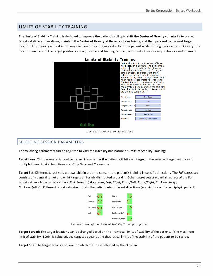
Bertec Corporation Bertec Workbook
79
LIMITS OF STABILITY TRAINING
The Limits of Stability Training is designed to improve the patient’s ability to shift the Center of Gravity voluntarily to preset targets at different locations, maintain the Center of Gravity at these positions briefly, and then proceed to the next target location. This training aims at improving reaction time and sway velocity of the patient while shifting their Center of Gravity. The locations and size of the target positions are adjustable and training can be performed either in a sequential or random mode.
Limits of Stability Training interface
SELECTING SESSION PARAMETERS
The following parameters can be adjusted to vary the intensity and nature of Limits of Stability Training:
Repetitions: This parameter is used to determine whether the patient will hit each target in the selected target set once or multiple times. Available options are: Only Once and Continuous.
Target Set: Different target sets are available in order to concentrate patient’s training in specific directions. The Full target set consists of a central target and eight targets uniformly distributed around it. Other target sets are partial subsets of the Full target set. Available target sets are: Full, Forward, Backward, Left, Right, Front/Left, Front/Right, Backward/Left, Backward/Right. Different target sets aim to train the patient into different directions (e.g. right side of a hemiplegic patient).
Full
Forward
Backward
Left
Right
Front/Left
Front/Right
Backward/Left
Backward/Right Representation of the Limits of Stability Training target sets
Target Spread: The target locations can be changed based on the individual limits of stability of the patient. If the maximum limit of stability (100%) is selected, the targets appear at the theoretical limits of the stability of the patient to be tested.
Target Size: The target area is a square for which the size is selected by the clinician.

Bertec Corporation Bertec Workbook
80
Order: The order of appearance of the targets can be changed to increase the level of training challenge to the patient. If Sequential is selected, the targets in the selected set will appear in a counterclockwise manner. On the other hand, selecting Random for the target order will make them appear in a random fashion so that the patient will not be able to predict the location of the next target.
Hold Time: This parameter specifies the duration for which the patient is required to keep the Center of Gravity in the highlighted target before moving to the next target.
The Limits of Stability Training is to be performed on the rigid Balance Plate surface only. Trying to use the balance foam or perturbed surface might cause the patient to loose balance and result in injury. THE HANDRAIL SYSTEM ALONE IS NOT DESIGNED TO PREVENT THE PATIENT FROM FALLING. IT IS ONLY AN ASSISTIVE DEVICE TO IMPROVE THE PATIENT’S BALANCE DURING BALANCE TRAINING. THEREFORE, THE PHYSICIAN CONDUCTING THE TESTS SHOULD ALWAYS BE ALERT OF THE PATIENT’S MOVEMENTS ON THE BALANCE PLATE. IT IS THE PHYSICIAN’S RESPONSIBILITY TO MAKE SURE THAT THE PATIENT IS ALWAYS SAFE WHILE USING THE BALANCECHECK SYSTEM. PROPER USE OF THE SUPPORT STRUCTURE, HARNESS, AND SHOULDER STRAPS IS REQUIRED TO PREVENT PATIENT FALLS AND/OR INJURIES DURING TRAINING, ESPECIALLY TRAINING ON ONE FOOT.
OPERATIONAL STEPS
• Select the Repetitions mode by clicking the "Repetitions" button.
• Select "Target Set" to match the direction into which the patient is to be trained.
• Select the locations of the target based on the limit of stability of the patient using the "Target Spread" option.
• Select the "Target Size" option.
• Enter the time duration for the patient to keep their Center of Gravity in the target areas in the "Hold Time" option.
• Have the patient step on to the Balance Platform. Note that depending on the general physical condition, the patient might need to get support from the handrail structure during training. Therefore, adjust the height of the handrail so that the patient can comfortably hold on to it.
• Make sure that as the patient is standing erect at a neutral posture, the Center of Gravity cursor (+) is approximately located in the center of the black test area.
• Click the "Start" button at the lower left hand side of the window to begin training.
• After clicking "Start", the selected target set will appear on the screen along with the cross showing the Center of Gravity of the patient.
• The patient is required to shift their Center of Gravity, shown as a cross, to the target highlighted in red color as quickly as possible and hold in the target area for the duration specified by the "Hold Time" parameter.
• If the repetition option is selected as "One Time", training will stop after each target is hit once. If the repetition option is "Continuous", then training should be stopped by the training administrator by clicking the "Stop" button.
• After training is finished, help the patient get off the Balance Platform.

Bertec Corporation Bertec Workbook
81
HOW DO I..?
CREATE A NEW PATIENT?
After logging into the program, click the Patients tab, and then select the New Patient item. The top gray silhouette image will change to the text "Click here to start a new patient". Click this, and that will access the Patient Information dialog to let you enter information about your new patient. Click the Save Changes button at the bottom-right of this to complete the entry, and automatically select the patient.
DELETE AN EXISTING PATIENT?
After logging into the program, click the Patients tab, and then select the existing patient you wish to delete. If the patient has a picture with it, then their picture will show, otherwise the default gray silhouette image will be shown. Click the image with the blue pencil, and that will access the Patient Information dialog. Click the Delete Patient button at the bottom right of this to delete the patient.
DELETE A TEST RESULT?
Once a test has been completed, there is currently no way to delete or modify the results.
ADD NEW PROTOCOLS TO THE WORKBOOK PROGRAM?
Depending on your service channel or vendor, additional protocols may be made available to you. Bertec Corporation has protocols packages such as BalanceCheck Screen and BalanceCheck Trainer that are part of the system and are licensed per installation.
If you are interested in developing your own protocols, please contact Bertec Corporation for our development kit.

Bertec Corporation Bertec Workbook
82
TROUBLESHOOTING Problem: the Workbook program is not capturing data Solution: make sure that a compatible Bertec device is connected via the USB cable and that the current drivers are installed. If the Workbook program cannot detect the device, or that it has faulted in some other way, the bottom bar of the program will be in bright red:
If the device is connected and Workbook still does not see the device, exit the application and reinstall it. If that does not resolve the program, contact Bertec Technical Support.
Problem: the Bertec device reads incorrect data, such as too much weight on the plate
Solution: the plate cannot be auto-zeroed and will need to be manually zeroed out. Select the Workbook icon on the top-right of the program's window, and select Zero Plate Load. If that does not resolve the program, contact Bertec Technical Support.
Problem: when I select Email a Report, I get a program crash error in Windows. Solution: the Email report button works by using your Windows email client. If you email uses a web-browser based email (for example, Google Email), then the Email Report button will not work.
Problem: Workbook tells me that my license key is no longer valid. Solution: please contact Bertec Technical Support for assistance with this problem.
For any other issues, please contact Bertec Technical Support.

Bertec Corporation Bertec Workbook
83
DOCUMENT REVISION HISTORY
Date Revision Description Author 7/3/2009 1.00 Initial Revision Todd Wilson 7/29/2009 1.01 Updated with final protocol names & graphics Todd Wilson 8/7/2009 1.02 Updated with to autostart changes, plus
header/footer graphics Todd Wilson
9/22/2009 1.03 Updated with How Do I section Todd Wilson 2/25/2010 1.04 Updated screenshots and patient listings Todd Wilson 1/11/2011 1.05 Updated with new configuration options Todd Wilson 5/21/2011 1.06 Updated screenshots and wording Todd Wilson 5/2/2012 1.07 Updated documentation to reflect changes to
Workbook version 1.1 Todd Wilson
3/2/2014 1.20 Updated documentation to reflect changes to Workbook version 1.2
Todd Wilson