Berkshire Owner’s Manual - Kirkland Fireplace -...
46
Featuring the Burner • Direct Vent Freestanding Stove • Natural Gas or Propane • Vent Horizontally or Vertically • Standard Residential • Mobile Home Approved Tested and Listed by Omni-Test Laboratories, Inc. Beaverton, Oregon Report # 028–S–28-5 ANSI Z21.88, WARNING: If the information in these instructions is not followed exactly, a fire or explosion may result causing property damage, personal injury or loss of life. - Do not store or use gasoline or other flammable vapors and liquids in the vicinity of this or any other appliance. WHAT TO DO IF YOU SMELL GAS • Do not try to light any appliance. • Do not touch any electrical switch; do not use any phone in your building. • Immediately call gas supplier from a neighbor's phone. Follow the gas supplier's instructions. • If you cannot reach your gas supplier, call the fire department. - Installation and service must be performed by a qualified installer, service agency or the gas supplier. This appliance may be installed as an OEM installation in a manufactured (mobile) home and must be installed in accordance with the manufacturer’s instructions and the manufactured home construction and safety standard, Title 24 CFR, Part 3280 or Standard for Installation in Mobile Homes, CAN/CSA Z240 MH. This appliance is only for use with the type(s) of gas indicated on the rating plate. A conversion kit is supplied with the appliance. Berkshire Owner’s Manual Installer: After installation give this manual to the home-owner and explain operation of this heater. Copyright 2004, T.I. $10.00 100-01159 4040621 4800 Harbour Pointe Blvd. SW Mukilteo, WA 98275
-
Upload
hoangkhanh -
Category
Documents
-
view
216 -
download
1
Transcript of Berkshire Owner’s Manual - Kirkland Fireplace -...

Featuring the
Burner
• Direct Vent Freestanding Stove
• Natural Gas or Propane
• Vent Horizontally or Vertically
• Standard Residential
• Mobile Home ApprovedTested and Listed by
Omni-Test Laboratories, Inc.Beaverton, Oregon
Report # 028–S–28-5ANSI Z21.88,
WARNING: If the information in these instructions is not followed exactly, a fire or explosionmay result causing property damage, personal injury or loss of life.
- Do not store or use gasoline or other flammable vapors and liquids in the vicinity of this orany other appliance.
WHAT TO DO IF YOU SMELL GAS• Do not try to light any appliance.• Do not touch any electrical switch; do not use any phone in your building.• Immediately call gas supplier from a neighbor's phone. Follow the gas supplier's instructions.• If you cannot reach your gas supplier, call the fire department.
- Installation and service must be performed by a qualified installer, service agency or the gassupplier.
This appliance may be installed as an OEM installation in a manufactured (mobile) home andmust be installed in accordance with the manufacturer’s instructions and the manufacturedhome construction and safety standard, Title 24 CFR, Part 3280 or Standard for Installation inMobile Homes, CAN/CSA Z240 MH.
This appliance is only for use with the type(s) of gas indicated on the rating plate. A conversionkit is supplied with the appliance.
Berkshire Owner’s ManualInstaller: After installation give this manual to the home-owner
and explain operation of this heater.
Copyright 2004, T.I. $10.00 100-01159 4040621
4800 Harbour Pointe Blvd. SWMukilteo, WA 98275

2 Introduction
Travis Industries 100-01159 4040621
Introduction
We welcome you as a new owner of a Lopi Berkshire stove. In purchasing a Berkshire you have joinedthe growing ranks of concerned individuals whose selection of an energy system reflects both aconcern for the environment and aesthetics. The Berkshire is one of the finest home heaters theworld over. This manual will explain the installation, operation, and maintenance of this stove. Pleasefamiliarize yourself with the Owner's Manual before operating your heater and save the manual forfuture reference. Included are helpful hints and suggestions that will make the operation andmaintenance of your new stove an easier and more enjoyable experience. We offer our continualsupport and guidance to help you achieve the maximum benefit and enjoyment from your heater.
Important InformationNo other Berkshire Stove has the same serial numberas yours. The serial number is on the listing platechained to the gas control valve.
This serial number will be needed in case you requireservice of any type.
Model: Lopi Berkshire Stove
Serial Number:
Purchase Date:
Purchased From:
Mail your Warranty CardToday, and Save Your Bill ofSa le .
To receive full warranty coverage,you will need to show evidence ofthe date you purchased yourheater. Do not mail your Bill ofSale to us.
We suggest that you attach yourBill of Sale to this page so that youwill have all the information youneed in one place should the needfor service or information occur.

Table of Contents 3
Travis Industries 100-01159 4040621
IntroductionIntroduction & Important Information................2
Safety PrecautionsSafety Precautions ......................................4
Features & SpecificationsFeatures ....................................................6
Installation Options......................................6
Heating Specifications..................................6
Dimensions.................................................6
InstallationInstallation Warning......................................7
Packing List................................................7
Additional Items Required for Installation..........7
Installation Overview....................................7
Installation Hints..........................................8
Stove Clearances ........................................8Mobile Home Requirements............................8
Heater Placement Requirements.....................9
Floor Protection Requirements........................9
Gas Line Installation.....................................10
Vent Requirements.......................................11
Approved Vent Configurations........................12
Restrictor Position...................................12
Measuring Vent Lengths...........................12
Vertical Term. with 0, 2, or 4 45° Elbows .......13
Hor. Term. with 1 90° Elbow........................14
Hor. Term. with 2 Elbows...........................15
Hor. Term. with 3 Elbows...........................16
Vertical Term. with 2 90° Elbows .................17
Vertical Term. with 3 Elbows......................18
Vent Termination Requirements ......................19
Finalizing the InstallationLeak Test ...................................................20
Pilot Adjustment (if necessary) .......................20
Air Shutter Adjustment (if necessary)...............20
Check Flame...............................................21
Glass Removal (& installation) ........................22
Log Installation............................................23
OperationBefore You Begin.........................................24
Location of Controls .....................................24
Starting The Pilot .........................................25
Starting the Stove for the First Time.................26
Turning the Stove On and Off .........................26
Adjusting the Flame Height.............................26
Adjusting the Blower Speed (optional) ..............27
Normal Operating Sounds..............................27
Normal Operating Odors................................27
MaintenanceMaintaining Your Stove’s Appearance..............28
Yearly Service Procedure..............................28
Troubleshooting Table...................................29
How this Stove Works...................................30
What Turns the Main Burners On and Off......30
What Prevents Gas Buildup.......................30
Wiring Diagram ............................................31
Replacement Parts List .................................31
Safety LabelSafety (Listing) Label....................................32
WarrantyWarranty ....................................................33
Optional EquipmentOptional Accessories ...................................34
LP Conversion Kit ........................................35
Blower .......................................................38
Fireback.....................................................40
Stone Or Cast Insert.....................................41
Installation AddendaClass A Chimney Conversion..........................44
Interior Masonry Chimney Conversion..............45
Index Index.........................................................46

4 Safety Precautions
Travis Industries 100-01159 4040621
• IF YOU SMELL GAS:* Do not light any appliance
* Extinguish any open flame
* Do not touch any electrical switch or plug or unplug anything
* Open windows and vacate building
* Call gas supplier from neighbor's house, if not reached, call firedepartment
• This unit must be installed by a qualified installer to prevent thepossibility of an explosion. Your dealer will know the requirements inyour area and can inform you of those people considered qualified.The room heater should be inspected before use and at least annuallyby a qualified service person. More frequent cleaning may berequired due to excessive lint from carpeting, bedding material, etc.
• The instructions in this manual must be strictly adhered to. Do not use makeshiftmethods or compromise in the installation. Improper installation will void the warrantyand safety listing.
For LPG only | Pout 11” W.C.
Look for this label:
If the label is present, the heater is equipped for LP (propane). If the label is absent, the heater is equipped for NG (natural gas).
• This heater is either approved for naturalgas (NG) or for propane (LP or LPG).Burning the incorrect fuel will void thewarranty and safety listing and may causean extreme safety hazard. Directquestions about the type of fuel used toyour dealer. Check for the label shown tothe right.
Ok
• Contact your local buildingofficials to obtain a permitand information on anyinstallation restrictions orinspection requirements inyour area. Notify yourinsurance company of thisheater as well.
• If the flame becomes sooty,dark orange in color, orextremely tall, do notoperate the heater. Callyour dealer and arrange forproper servicing.
• It is imperative that controlcompartments, screens, orcirculating air passagewaysof the heater be kept cleanand free of obstructions.These areas provide the airnecessary for safeoperation.
?• Do not operate the heater if
it is not operating properly inany fashion or if you areuncertain. Call your dealerfor a full explanation of yourheater and what to expect.
Gas
• Do not store or use gasolineor other flammable liquids inthe vicinity of this heater.
AAAAAAAAAAAAAAAAA
• Do not use this appliance ifany part has been underwater. Immediately call aqualified service technicianto inspect the appliance andto replace any part of thecontrol system and any gascontrol which has beenunder water.

Safety Precautions 5
Travis Industries 100-01159 4040621
• Do not place clothing orother flammable items on ornear the heater. Becausethis heater can be controlledby a thermostat there is apossibility of the heaterturning on and igniting anyitems placed on or near it.
AAAAAAAAA
• Light the heater using thebuilt-in piezo igniter. Do notuse matches or any otherexternal device to light yourheater.
• Never remove, replace,modify or substitute any partof the heater unless
• The viewing glass should beopened only for lighting thepilot or conducting service.
• Any safety screen or guardremoved for servicing mustbe replaced prior tooperating the heater.
• Do not operate with theglass removed or damaged.
instructions are given in thismanual. All other work mustbe done by a trainedtechnician. Don't modify orreplace orifices.
• Allow the heater to coolbefore carrying out anymaintenance or cleaning.
• Operate the heateraccording to the instructionsincluded in this manual.
• If the main burners do notstart correctly turn the gasoff at the gas control valveand call your dealer forservice.
• The pilot flame must contactthe thermopile andthermocouple (see theillustration to the left). If itdoes not, turn the gascontrol valve to "OFF" andcall your dealer.
AAAA • This unit is not for use with
solid fuel
• Do not place anything insidethe firebox (except theincluded fiber logs).
• If the fiber logs becomedamaged, replace withTravis Industries log set.
ThisManual
• Do not throw this manualaway. This manual hasimportant operating andmaintenance instructionsthat you will need at a latertime. Always follow theinstructions in this manual.
• Children and adults shouldbe alerted to the hazards ofhigh surface temperatureand should stay away toavoid burns or clothingignition. Young childrenshould be supervised whenthey are in the same room asthe heater.
• Plug the heater into a120V grounded electricaloutlet. Do not remove thegrounding plug.
• Don’t route the electricalcord in front of, over, orunder the heater
• Instruct everyone in thehouse how to shut gas off tothe appliance and at the gasmain shutoff valve. The gasmain shutoff valve is usuallynext to the gas meter orpropane tank and requires awrench to shut off.
• Travis Industries, Inc.grants no warranty,implied or stated, forthe installation ormaintenance of yourheater, and assumesno responsibility of anyconsequentialdamage(s).

6 Specifications
Travis Industries 100-01159 4040621
Features:- Ember Fyre™ Burner for "Wood Fire" Look- Works During Power Outages (millivolt system)- High Efficiency- Optional Thermostat or Remote Control- Optional Blower for Quicker Heat Distribution- Convenient Operating Controls- Variable-Rate Heat Output- Low Maintenance
Installation Options:- Freestanding Stove
- Horizontal or Vertical Vent
- Residential or Mobile Home
- Straight or Corner Placement
- Bedroom Approved
Heating Specifications:Approximate Heating Capacity (in square feet)*............500 - 1,500 with Blower, 500 to 1,200 WithoutMaximum Input ........................................................................................31,000Output from Low to High (in BTU’s per hour)..............................................16,608 to 26,815Steady State Efficiency............................................................................up to 86.5%AFUE (without blower) .............................................................................Up to 67.2%• Heating capacity will vary depending on the home’s floor plan, degree of insulation, and the outside
temperature.** Efficiency rating is a product of thermal efficiency rating determined under continuous operation independent
of installed system.
Dimensions & Weight:
Weight: 215 Lbs.
NOTE:
Measure side, corner,
and back clearances
from the stove top.
19" 4-7/8"26-3/4" The flue collar protrudes
7/8" above the stove top
28-1/8"
16-1/8"
Electrical Specifications (for optional blower)Electrical Rating.........................................................115 Volts, 1.3 Amps, 60 Hz (150 watts on high)
Fuel:This heater is shipped in natural gas (NG) configuration but may be converted to propane (LP) usingthe included LP conversion kit. The sticker on top of the gas control valve will verify the correct fuel.

Installation (for qualified installers only) 7
Travis Industries 100-01159 4040621
Installation Warnings:! Failure to follow all of the requirements may result in property damage, bodily
injury, or even death.! This heater must be installed by a qualified installer who has gone through a
training program for the installation of direct vent gas appliances.! This appliance must be installed in accordance with all local codes, if any; if not, in
U.S.A. follow ANSI Z223.1 and NFPA 54(88), in Canada follow B-149.! In Manufactured or Mobile Homes must conform with: In USA, Manufactured Home
Construction and Safety Standard, Title 24 CFR, Part 3280; In Canada, CSA Z240.4and Gas-Equipped Recreational Vehicles and Mobile Housing. This appliance maybe installed in Manufactured Housing only after the home is site located.
! This stove is designed to operate on natural gas or propane (LP).! All exhaust gases must be vented outside the structure of the living-area.
Combustion air is drawn from outside the living-area structure.! Notify your insurance company before hooking up this stove.! The requirements listed below are divided into sections. All requirements must be
met simultaneously. The order of installation is not rigid – the qualified installershould follow the procedure best suited for the installation.
Packing List• Propane Conversion Kit• Log Set• 4” Pipe, 8” Pipe, and 90° Elbow (for gas inlet)• Glass Latch Tool (to un-latch glass frame)• Touch-Up Paint• 4 Screws & Clips (Fyrestone only) for stone inserts• Cover Plate with Knob (for the Aroma-Therapy option)
Additional Items Required• Vent (see “Venting Requirements” for details)• Gas Line Equipment (shutoff valve, pipe, etc.)
Additional Accessories Required• Enameled Units are shipped without the top and side
inserts - see "Stone or Cast Insert Installation" on page 42.
Installation Overview
See "Vent Requirements"
See "Floor Protection Requirements"
See "Gas Line Installation"
AAAAAAAAAAAAAAAAAAAAAAAAAAAAAAAAAAAAAAAAAAAAAAAAAAAAAAAAAAAAAAAAAAAAAAAAAAAAAAAAAAAAAAAAAAAAAAAAAAAAAAAAAAAAAAAAAAAAAAAAAAAAAAAAAAAAAAAAAAAAAAAAAAAAAAAAAAAAAAAAAAAAAAAAAAAAAAAAAAAAAAAAAAAAAAAAAAAAAAAAAAAAAAAAAAAAAAAAAAAAAAAAAAAAAAAAAAAAAAAAAAAAAAAAAAAAAAAAAAAAAAAAAAAAAAAAAAAAAAAAAAAAAAAAAAAAAAAAAAAAAAAAAAAAAAAAAAAAAAAAAAAAAAAAAAAAAAAAAAAAAAAAAAAAAAAAAAAAAAAAAAAAAAAAAAAAAAAAAAAAAAAAAAAAAAAAAAAAAAAAAAAAAAAAAAAAAAAAAAAAAAAAAAAAAAAAAAAAAAAAAAAAAAAAAAAAAAAAAAAAAAAAAAAAAAAAAAAAAAAAAAAAAAAAAAAAAAAAAAAAAAAAAAAAAAAAAAAAAAAAAAAAAAAAAAAAAAAAAAAAAAAAAAAAAAAAAAAAAAAAAAAAAAAAAA
AAAAAAAAAAAAAAAAAAAAAAAAAAAAAAAAAAAAAAAAAAAAAAAAAAAAAAAAAAAAAAAAAAAAAAAAAAAAAAAAAAAAAAAAAAAAAAAAAAAAAAAAAAAAAAAAAAAAAAAAAAAAAAAAAAAAAAAAAAAAAAAAAAAAAAAAAAAAAAAAAAAAAAAAAAAAAAAAAAAAAAAAAAAAAAAAAAAAAAAAAAAAAAAAAAAAAAAAAAAAAAAAAAAAAAAAAAAAAAAAAAAAAAAAAAAAAAAAAAAAAAAAAAAAAAAAAAAAAAAAAAAAAAAAAAAAAAAAAAAAAAAAAAAAAAAAAAAAAAAAAAAAAAAAAAAAAAAAAAAAAAAAAAAAAAAAAAAAAAAAAAAAAAAAAAAAAAAAAAAAAAAAAAAAAAAAAAAAAAAAAAAAAAAAAAAAAAAAAAAAAAAAAAAAAAAAAAAAAAAAAAAAAAAAAAAAAAAAAAAAAAAAAAAAAAAAAAAAAAAAAAAAAAAAAAAAAAAAAAAAAAAAAAAAAAAAAAAAAAAAAAAAAAAAAAAAAAAAAAAAAAAAAAAAAAAAAAAAAAAAAAAAAAAAAA
AAAAAAAAAAAAAAAAAAAAAAAAAAAAAAAAAAAAAAAAAAAAAAAAAAAAAAAAAAAAAAAAAAAAAAAAAAAAAAAAAAAAAAAAAAAAAAAAAAAAAAAAAAAAAAAAAAAAAAAAAAAAAAAAAAAAAAAAAAAAAAAAAAAAAAAAAAAAAAAAAAAAAAAAAAAAAAAAAAAAAAAAAAA
AAAAAAAAAAAAAAAAAA
AAAAAAAAAAAAAAAAAAAAAAAAA
See "Clearances"

8 Installation (for qualified installers only)
Travis Industries 100-01159 4040621
Installation Hints:
1. If converting to LP, convert the appliance prior to installation.
2. The blower is easiest to install prior to installation. Because the blower is located near the gas inletlocation, we recommend using the included pipe and elbow to route the gas inlet around the blowerposition.
3. Install the logs last - they are fragile.
4. When determining the location of the stove, locate the wall studs (for horizontal penetrations) andceiling trusses (for vertical penetrations). You may wish to adjust the stove position slightly to ensurethe vent does not intersect with a framing member.
5. Fumes and smoke from the paint curing and oil burning off the steel may occur the first time you startthis heater. This is normal. We recommend you open windows to vent the room.
Stove Clearances
10" Min.
5" Min.
Straight Installations Corner Installations
With this clearance, the vent is
centered 15-3/4" from the
wall.
5" Min.
AAAAAAAAAWith this clearance the
vent is centered 7-1/8"
from the back wall, 23-1/2"
from the side wall.
45°
Mobile Home Requirements
• When the stove is installed in a mobile home, it must be bolted to the floor and the appliancegrounded (use the optional blower with a grounded circuit or other suitable grounding method -current ANSI/NFPA 70 or CSA C22.1).

Installation (for qualified installers only) 9
Travis Industries 100-01159 4040621
Heater Placement Requirements
• Heater must be installed on a level surface capable of supporting the heater and vent
• Due to the high temperature, the heater should be located out of traffic and away fromfurniture and draperies.
? When placed in a location where the floor to ceiling height is under 7 feet, the installationis considered an alcove and must meet the following requirements:• The alcove floor to ceiling height must be at least 58” tall• The alcove must not be more than 45” deep before the ceiling returns to 7’• The alcove must be at least 46-3/4” wide
• The heater must not be placed so the vents below or above the door, along the sides ofheater, or along the back of the heater can become blocked.
• This heater may be placed in a bedroom. Please be aware of the large amount of heat thisappliance produces when determining a location.
Floor Protection Requirements
• When the stove is installed directly on carpeting, vinyl or other combustible material otherthan wood flooring or a high pressure laminate wood floor, the stove must be installed ona metal or wood protection panel extending the full width and depth of the heater(Minimum 26-3/4” wide by 19” deep).
Make sure these rubber tipped bolts on each leg contact the floor (they dampen any noise that may transmit through the hearth). Do not adjust with weight on the legs, the rubber tips may tear.

10 Installation (for qualified installers only)
Travis Industries 100-01159 4040621
Gas Line Installation
! The gas line must be installed in accordance with all local codes, if any; if not, follow current ANSIZ223.1 or NFPA 54 in the USA and the current CGA B149 in Canada.
! The heater and gas control valve must be disconnected from the gas supply piping during anypressure testing of that system at test pressures in excess of 1/2 psig (3.45 kPA). For pressuresunder 1/2 psig (3.45 kPA), isolate the gas supply piping by closing the manual shutoff valve.
• This heater is designed for natural gas but can be converted to propane. Check the sticker ontop of the gas control valve to verify the correct fuel is used (see page 4).
• Leak test all gas line joints and the gas control valve prior to and after starting the heater.
• The gas inlet accepts a 3/8” F.P.T. Fitting
• The location of the gas inlet is shown below
• A manual shutoff valve is required for installation (it must be located within 3’ of the heater).T-Handle gas cocks are required in Massachusetts in compliance with code 248CMR.
1-3/8"6-3/8" (standard legs)8-3/4" (tall legs)
9-3/4" ACenterlin
e
With the included pipe installed, the gas inlet is located at the location shown below.
Gas Inlet Pressure• With the heater off, the inlet pressure must meet the requirements listed in the table below
• If the pressure is not sufficient, make sure the piping used is large enough and the total gas loadfor the residence does not exceed the amount supplied.
• The supply regulator (the regulator that attaches directly to the residence inlet or to the propanetank) should supply gas at the suggested input pressure listed below. Contact the local gassupplier if the regulator is at an improper pressure.
Standard Input Pressure
Natural Gas 7” W.C. (1.74 Kpa)
Propane 13” W.C. (3.23 Kpa)

Installation (for qualified installers only) 11
Travis Industries 100-01159 4040621
Vent Requirements
! Always maintain the required 1” clearance (air space) to combustible materials to prevent a fire hazard.Do not fill air spaces with insulation.
! The gas appliance and vent system must be vented directly to the outside of the building, and neverbe attached to a chimney serving a separate solid fuel or gas-burning appliance. Each direct vent gasappliance must use it’s own separate vent system.
• This appliance is equipped only foraltitudes 0-2000 feet. However,our in-house testing has shownthat the unit operated at altitudes to8000 ft.
! Failure to adjust the air shutterproperly may lead to impropercombustion which can create asafety hazard. Consult your dealeror installer if you suspect animproperly adjusted air shutter.
• When the vent passes through awall, a wall thimble is required.When the vent passes through aceiling, a support box or firestop isrequired. When the vent passesthrough the roof, a roof flashingand storm collar are required.Follow the instructions providedwith the vent for installing theseitems.
Use a firestop spacer whenever passing through a ceiling
Vertical Termination NOTE: always use the "high-wind" version (if applicable)
Use a roof flashing and storm collar whenever passing through the roof
Use a support box on exposed vent
Vertical Vent Requirements
Use a firestop whenever passing through a wall
Horizontal TerminationMaintain a minimum 1" clearance from vent to any combustible.
Minimum Framing for wall thimble
Horizontal Vent Requirements
Minimum framing for fire stop Maintain a minimum 1"
clearance from vent to any combustible
8-5/8"
8-5/8"
• Use of of the following 6-5/8" diameter co-axial gas direct vent systems:
Manuafacturer Series
Simpson Dura-Vent Model GS
Selkirk Hearth Products Direct-Temp
American Metal Products Ameri-Vent
N O T E : Always use the high-wind cap for the type of vent you are using (if applicable)
• Slide the vent sections together and turn 1/4 turn until the sections lock in place.
• Screws are not required to secure the vent. However, three screws may be used tosecure vent sections together if desired.
• High temperature sealant is recommended at the appliance starter section connection(use high-temperature silicone or Mill-Pac®).
• If disassembly is required, at time of re-assembly check to see if the vent creates a tightfit. If it does not, apply high temperature sealant to the joints of the affected sections.
• Horizontal sections require a 1/4" rise every 12" of travel
• Horizontal sections require non-combustible support every three feet (e.g.: plumbingtape)

12 Installation (for qualified installers only)
Travis Industries 100-01159 4040621
Approved Vent ConfigurationsRestrictor Position
• A restrictor is built into the appliance to control the flow rate of exhaust gases. This ensures properflames for the wide variety of vent configurations. Depending upon the vent configuration, you maybe required to adjust the restrictor position. The charts for approved vent configurations describewhich position the vent restrictor must be in.
Loosen (or remove) the screw and locking tab under the stove top.
Phillips Screwdriver
a
b
Use both hands to pull the stove top forward, rotate it up, then lift it off the stove.
To Adjust the RestrictorTo Access the Restrictor
NOTE: The restrictor is shipped in position #1.
This restrictor is in position # 6
Lift the cotter pin out.
a Slide the restrictor adjustment rod in.b Replace the cotter pin
through the correct hole on the restrictor adjustment rod.
c
Restrictor Positions
# 2
# 4
# 6
# 3
# 5
# 1
Measuring Vent Lengths
Vent Horizontal Run
Vent Horizontal Run is measured from the start of the horizontal section to the end of the termination.
Vent Height is calculated to the top of the vent on horizontal terminations and to the top of the termination on vertical terminations.
Vent Height
Vertical Elbow
NOTE:When a horizontal elbow (90° or 45°) is used, horizontal length is the sum of the two lengths (H1 + H2).
H1
H2
Horizontal Elbow
Vertical Elbow

Installation (for qualified installers only) 13
Travis Industries 100-01159 4040621
Approved Venting Configurations for Vertical Terminations withZero, Two, or Four 45° Elbows
• 10’ Minimum SystemHeight(with or without offsets)
• 40’ Maximum SystemHeight
• 24’ Maximum Offset
• The termination must fallwithin the shaded areashown in the chart. Usethe indicated restrictorposition.
• If using offsets, use thetable below to calculate thevertical rise and horizontaloffset
Offset Length
Horizontal Offset
Vertical Rise
Offset Length Hor. Offset Vert. Rise
None 5” 1’
1’ Section 1’ 1’ 7”
2’ Section 1’ 9” 2’ 4”
3’ Section 2’ 5” 3’
4’ Section 3’ 2” 3’ 8”
4’ + 1’ Section 3’ 9” 4’ 4”
4’ + 2’ Section 4’ 6” 5’
4’ + 3’ Section 5’ 2” 5’ 9”
4’ + 4’ Section 6’ 6’ 9”
AAAAAAAAAAAAAAAAAAAAAAAAAAAAAAAAAAAAAAAAAAAAAAAAAAAAAAAAAAAAAAAAAAAAAAAAAAAAAAAAAAAAAAAAAAAAAAAAAAAAAAAAAAAAAAAAAAAAAAAAAAAAAAAAAAAAAAAAAAAAAAAAAAAAAAAAAAAAAAAAAAAAAAAAAAAAAAAAAAAAAAAAAAAAAAAAAAAAAAAAAAAAAAAAAAAAAAAAAAAAAAAAAAAAAAAAAAAAAAAAAAAAAAAAAAAAAAAAAAAAAAAAAAAAAAAAAAAAAAAAAAAAAAAAAAAAAAAAAAAAAAAAAAAAAAAAAAAAAAAAAAAAAAAAAAAAAAAAAAAAAAAAAAAAAAAAAAAAAAAAAAAAAAAAAAAAAAAAAAAAAAAAAAAAAAAAAAAAAAAAAAAAAAAAAAAAAAAAAAAAAAAAAAAAAAAAAAAAAAAAAAAAAAAAAAAAAAAA
5 feet
10 feet
15 feet
20 feet
25 feet
30 feet
0 feet
40' (max)
5 feet
0 feet
0 fe
et
5 fe
et
10 feet
15 feet
20 feet
25 feet
30 feet
40' (max)
Restrictor Position # 5
NOTE:
Restrictor positions are based
upon lab tests. The ideal
restrictor position may vary
slightly, especially when the
termination is near a
demarkation line.
Restrictor Position # 6
10 fe
et
15 fe
et
20 fe
et
24 '
(max
)
0 fe
et
5 fe
et
10 fe
et
15 fe
et
20 fe
et
24 '
(max
)
35 feet35 feet

14 Installation (for qualified installers only)
Travis Industries 100-01159 4040621
Approved Venting Configurations with a Horizontal Terminationand One 90° Elbow
• If using a Snorkel Termination (14” or 36”) add the snorkel height to the vertical height (snorkelterminations are used primarily for basement installations).
• The termination must fall within the shaded area shown in the chart. Use the indicated restrictorposition.
AAAAAAAAAAAAAAAAAAAAAAAAAAAAAAAAAAAAAAAAAAAAAAAAAAAAAAAAAAAAAAAAAAAAAAAAAAAAAAAAAAAAAAAAAAAAAAAAAAAAAAAAAAAAAAAAAAAAAAAAAAAAAAAAAAAAAAAAAAAAAAAAAAAAAAAAAAAAAAAAAAAAAAAAAAAAAAAAAAAAAAAAAAAAAAAAAAAAAAAAAAAAAAAAAAAAAAAAAAAAAAAAAAAAAAAAAAAAAAAAAAAAAAAAAAAAAAAAAAAAAAAAAAAAAAAAA
5 feet
10 feet
15 feet
19' (max)
0 feet
5 feet
0 feet
0 fe
et
5 fe
et
10 feet
15 feet
Restrictor Position # 5
NOTE:Restrictor positions are based upon lab tests. The ideal restrictor position may vary slightly, especially when the termination is near a demarkation line.
Restrictor Position # 1
10 fe
et
15 fe
et
20 fe
et
24 '
(max
)
0 fe
et
5 fe
et
10 fe
et
15 fe
et
20 fe
et
24 '
(max
)
19' (max)
NOTE: Horizontal sections require a 1/4" rise every 12" of travel.
NATURAL GAS: Min. 2' Section Required
PROPANE (LP): Min. 3' Section Required

Installation (for qualified installers only) 15
Travis Industries 100-01159 4040621
Approved Venting Configurations with a Horizontal Terminationand Two Elbows (one 90° vertical and one 90° or 45° horizontal elbow)
• If using a Snorkel Termination (14” or 36”) add the snorkel height to the vertical height (snorkelterminations are used primarily for basement installations).
• The termination must fall within the shaded area shown in the chart. Use the indicated restrictorposition.
AAAAAAAAAAAAAAAAAAAAAAAAAAAAAAAAAAAAAAAAAAAAAAAAAAAAAAAAAAAAAAAAAAAAAAAAAAAAAAAAAAAAAAAAAAAAAAAAAAAAAAAAAAAAAAAAAAAAAAAAAAAAAAAAAAAAAAAAAAAAAAAAAAAAAAAAAAAAAAAAAAAAAAAAAAAAAAAAAAAAAAAAAAAAAAAAAAAAAAAAAAAAAAAAAAAAAAAAAAAAAAAAAAAAAAAAAAAAAAAAAAAAAAAAAAAAAAAAAAAAAAAAAAAAAAAAAAAAAAAAAAAAAAAAAAAAAA
5 feet
10' (min)
15 feet
19' (max)
0 feet
5 feet
0 feet
0 fe
et
5 fe
et
10' (min)
15 feet
Restrictor Position # 5
NOTE:Restrictor positions are based upon lab tests. The ideal restrictor position may vary slightly, especially when the termination is near a demarkation line.
Restrictor Position # 1
10 fe
et
15 fe
et
20 fe
et
24 '
(max
)
0 fe
et
5 fe
et
10 fe
et
15 fe
et
20 fe
et
24 '
(max
)
19' (max)
NOTE: Horizontal sections require a 1/4" rise every 12" of travel.
This is considered a horizontal elbow (it does not matter whether it turns right or left).It may be a 90° or 45° elbow.
This is considered a vertical elbows
Horizontal length (max. 24') is calculated by adding both lengths of horizontal run (Horizontal Length = H1 + H2).
H1
H2
NATURAL GAS: Min. 2' Section Required
PROPANE (LP): Min. 3' Section Required

16 Installation (for qualified installers only)
Travis Industries 100-01159 4040621
Approved Venting Configurations with a Horizontal Terminationand Three 90° Elbows (all vertical)
• If using a Snorkel Termination (14” or 36”) add the snorkel height to the vertical height (snorkelterminations are used primarily for basement installations).
• The termination must fall within the shaded area shown in the chart. Use the indicated restrictorposition.
AAAAAAAAAAAAAAAAAAAAAAAAAAAAAAAAAAAAAAAAAAAAAAAAAAAAAAAAAAAAAAAAAAAAAAAAAAAAAAAAAAAAAAAAAAAAAAAAAAAAAAAAAAAAAAAAAAAAAAAAAAAAAAAAAAAAAAAAAAAAAAAAAAAAAAAAAAAAAAAAAAAAAAAAAAAAAAAAAAAAAAAAAAAAAAAAAAAAAAAAAAAAAAAAAAAAAAAAAAAA
5 feet
10' (min)
15 feet
21' (max)
0 feet
5 feet
0 feet
0 fe
et
5 fe
et
10' (min)
15 feet
Restrictor Position # 5
NOTE:Restrictor positions are based upon lab tests. The ideal restrictor position may vary slightly, especially when the termination is near a demarkation line.
Restrictor Position # 1
10 fe
et
15 fe
et
20 fe
et
24 '
(max
)
0 fe
et
5 fe
et
10 fe
et
15 fe
et
20 fe
et
24 '
(max
)
21' (max)
NOTE: Horizontal sections require a 1/4" rise every 12" of travel.
This is a horizontal elbow -NOT ALLOWED FOR THIS VENT CONFIGURATION
These are vertical elbows.
Installation (for qualified installers only) 17
Travis Industries 100-01159 4040621
Approved Venting Configurations for Vertical Terminations withTwo 90° Elbows• The termination must fall within the shaded area shown in the chart. Use the indicated restrictor
position.
AAAAAAAAAAAAAAAAAAAAAAAAAAAAAAAAAAAAAAAAAAAAAAAAAAAAAAAAAAAAAAAAAAAAAAAAAAAAAAAAAAAAAAAAAAAAAAAAAAAAAAAAAAAAAAAAAAAAAAAAAAAAAAAAAAAAAAAAAAAAAAAAAAAAAAAAAAAAAAAAAAAAAAAAAAAAAAAAAAAAAAAAAAAAAAAAAAAAAAAAAAAAAAAAAAAAAAAAAAAAAAAAAAAAAAAAAAAAAAAAAAAAAAAAAAAAAAAAAAAAAAAAAAAAAAAAAAAAAAAAAAAAAAAAAAAAAAAAAAAAAAAAAAAAAAAAAAAAAAAAAAAAAAAAAAAAAAAAAAAAAAAAAAAAAAAAAAAAAAAAAAAAAAAAAAAAAAAAAAAAAAAAAAAAAAAAAAAAAAAAAAAAAAAAAAAAAAAAAAAAAAAAAAAAAAAA
5 feet
10' (min)
15 feet
20 feet
25 feet
30 feet
0 feet
40' (max)
5 feet
0 feet
0 fe
et
5 fe
et
10' (min)
15 feet
20 feet
25 feet
30 feet
40' (max)
Restrictor Position # 5
NOTE:Restrictor positions are based upon lab tests. The ideal restrictor position may vary slightly, especially when the termination is near a demarkation line.
Restrictor Position # 6
10 fe
et
15 fe
et
20 fe
et
24 '
(max
)
0 fe
et
5 fe
et
10 fe
et
15 fe
et
20 fe
et
24 '
(max
)
35 feet35 feet
Restrictor Position # 1
NOTE: Horizontal sections require a 1/4" rise every 12" of travel.
This is a horizontal elbow -NOT ALLOWED FOR THIS VENT CONFIGURATION
These are vertical elbows.

18 Installation (for qualified installers only)
Travis Industries 100-01159 4040621
Approved Venting Configurations for Vertical Terminations withThree 90° Elbows (Two 90° Vertical and One 45° or 90° Horizontal Elbow)
• The termination must fall within the shaded area shown in the chart. Use the indicated restrictorposition.
AAAAAAAAAAAAAAAAAAAAAAAAAAAAAAAAAAAAAAAAAAAAAAAAAAAAAAAAAAAAAAAAAAAAAAAAAAAAAAAAAAAAAAAAAAAAAAAAAAAAAAAAAAAAAAAAAAAAAAAAAAAAAAAAAAAAAAAAAAAAAAAAAAAAAAAAAAAAAAAAAAAAAAAAAAAAAAAAAAAAAAAAAAAAAAAAAAAAAAAAAAAAAAAAAAAAAAAAAAAAAAAAAAAAAAAAAAAAAAAAAAAAAAAAAAAAAAAAAAAAAAAAAAAAAAAAAAAAAAAAAAAAAAAAAAAAAAAAAAAAAAAAAAAAAAAAAAAAAAAAAAAAAAAAAAAAAAAAAAAAAAAAAAAAAAAAAAAAAAAAAAAAAAAAAAAAAAAAAAAAAAAAAAAAAAAAAAAAAAAAAAAAAAAAAAAAAAAAAAAAAAAAAAAAAAAAAAAAA
5 feet
10' (min)
15 feet
20 feet
25 feet
30 feet
0 feet
40' (max)
5 feet
0 feet
0 fe
et
5 fe
et
10' (min)
15 feet
20 feet
25 feet
30 feet
40' (max)
Restrictor Position # 5
NOTE:
Restrictor positions are based
upon lab tests. The ideal
restrictor position may vary
slightly, especially when the
termination is near a demarkation
line.
10 fe
et
15 fe
et
20 fe
et
24 '
(max
)
0 fe
et
5 fe
et
10 fe
et
15 fe
et
20 fe
et
24 '
(max
)
35 feet35 feet
Restrictor Position # 1
NOTE:
Horizontal sections require a
1/4" rise every 12" of travel.
This is considered a horizontal elbow (it does not matter whether it turns right or left).It may be a 45° or 90° elbow.
This is considered a vertical elbow
Horizontal length (max. 24') is calculated by adding both lengths of horizontal run (Horizontal Length = H1 + H2).
H1
H2This is considered a vertical elbow

Installation (for qualified installers only) 19
Travis Industries 100-01159 4040621
Vent Termination Requirements (see illustration below)! Venting terminals shall not be recessed into a wall or siding.
A Minimum 9" clearance from any door or window
B Minimum 12" above any grade, veranda, porch, deck or balcony
C Minimum 12" from outside corner walls
D Minimum 12" from inside corner walls
E Minimum 11" clearance below unventilated soffits or roof surfacesMinimum 18" clearance below ventilated soffitsMinimum 6" clearance from roof eavesNOTE: Vinyl surfaces require 24"
11” Min.
6” Min.
Roof Surface
Roof Eaves
F Minimum 18" clearance below a veranda, porch, deck or balcony (must have two open sides)
G Minimum 48" clearance from any adjacent building
H Minimum 84" clearance above any grade when adjacent to public walkways or drivewaysNOTE: may not be used over a walkway or driveway shared by an adjacent building
I Minimum 48" clearance from any mechanical air supply inlet, 72" for Canada
J Minimum 36" clearance above and 48” below and to the sides of non-mechanical air supply inlet
K Minimum 36" from the area above the meter/regulator (vent outlet)
L Minimum 36" from the meter/regulator (vent outlet)
M Minimum 12” above the roof line (for vertical terminations)
*Note: In Canada the vent termination must be a minimum 2' (.6 M) tall and 2' (.6 M)above any portion of the roof within 10' (3 M) of the vent.
N Minimum 24” horizontal clearance to any surface (such as an exterior wall) – for vertical terminations
C
B
H
E
G A
DF
L
K J
I
NOTE: Measure clearances to the nearest edge of the exhaust hood.
AE
E
M
N
• Use the vinyl siding standoff (#1250) when installing on an exterior with vinyl siding.
• Vent termination must not be located where it will become plugged by snow or other material
• These clearances meet UMC-1994 and the CNA/CGA-B149 code standards.
20 Installation (for qualified installers only)
Travis Industries 100-01159 4040621
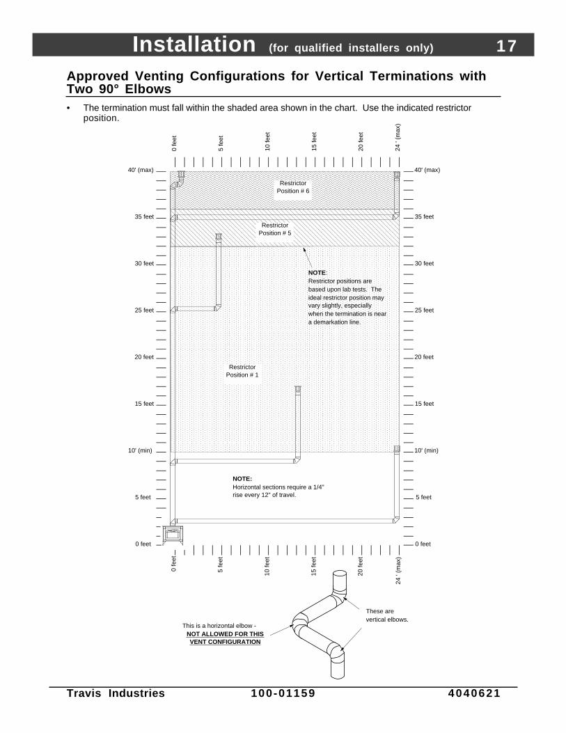
Finalizing the Installation! Make sure the gas control valve is “OFF” and the heater is cool prior to conducting service.
1 Remove the face and glass (see page 22)
2 Install the log set and coals (see page 23).
! We recommend you purge the gas line at this time (with the glass removed). This allows gas to bedetected once it enters the firebox, ensuring gas does not build up.
3 Replace and secure the glass and face (see page 22)
4 Turn on gas to the heater. Leak test all gas joints prior to starting the appliance. Start the pilot. Startthe main burner. Leak test all gas joints again.
5 Check the pilot flame to make sure it looks like the illustration below. Adjust the pilot flame if necessary.
Standard Screwdriver
The pilot flame must contact the thermocouple and
thermopile (see the illustration below). Adjust the pilot up or
down as necessary.
To adjust the pilot flame, turn this screw (NOTE: if totally
unscrewed gas will come out of this port). Clockwise
lowers the flame while counter-clockwise raises it.
6 Let the heater burn for thirty minutes. Adjust the air shutter, if necessary, to achieve the correctlooking flame (see the illustration below).
• The air shutter adjusts the amount of air that mixes with the gas before it exits the burner holes. It isused to fine-tune the flame for differences in altitude and vent configuration.
Gas Control Valve
NOTE: If the air shutter is all the way
open, yet the flames remain sooty, shut
off gas to the fireplace and contact a
qualified gas service technician.
CorrectFlames should be blue at the
base, yellow-orange on the top.
If the flames are over 14" tall or sooty on
the ends, open the air shutter.
Not Enough AirIf the flames are all blue and
short, close the air shutter.
Too Much Air
NOTE: The logs must be installed correctly to
monitor the flame while adjusting the air shutter.
Air Shutter Control
Pushing to the left gives the flame less air
(making it more orange). Pushing to the
right gives the flame more air, making it
more blue. For fine adjustments use a
screwdriver to tap the air shutter.
ADJUSTING THE AIR SHUTTER

Installation (for qualified installers only) 21
Travis Industries 100-01159 4040621
! If the vent configuration is installed incorrectly the vent may cause the flames inside the heater to lift or“ghost” – a dangerous situation. Inspect the flames after installation to insure proper performance. Ifthe vent configuration is correct, yet the flames are lifting or ghosting, shut off gas to the heater andcontact the dealer for information on remedying the problem.
! Failure to properly adjust the air shutter may lead to improper combustion and a safety hazard. Consultyour dealer or installer if you suspect an improperly
The flames should burn right off the top of the burner ports (if they are too blue, adjust the air control).
If the flames are lifting, yet the vent configuration is correct, contact your dealer.
Burner PanBurner Ports
(holes)
If the flames are ghosting, yet the vent configuration is correct, contact your dealer.
7 Turn the flame adjust knob to its highest position - the flames should be a maximum 9” to 10” tall.Check the flame on low position. The flames should burn off of each burner hole. If the heater doesnot work correctly, contact your dealer for a remedy.
8 Give this manual to the home owner and fully explain the operation of this heater.

22 Finalizing the Installation (for qualified installers only)
Travis Industries 100-01159 4040621
Face and Glass Removal
! Make sure the gas control valve is “OFF” and the heater is cool prior to conducting service.
Insert the
latch tool
into the hole
on the glass
frame latch.
Pull the latch
out then up
to detach it
from the
glass frame.
Use the latch tool to open the face latches
on both sides (hold the face to make sure it
does not fall forward).
With the face latches disengaged,
the face can be removed.
Grasp the glass frame and lift it up until
both the tabs at the bottom disengage
from the slotted holders. Then move the
glass frame forward, then down.
NOTE:
Enameled
parts can be
easily
damaged by
mis-handling.
AAAAAAAAA

Finalizing the Installation (for qualified installers only) 23
Travis Industries 100-01159 4040621
Log Installation! Make sure the gas control valve is “OFF” and the heater is cool prior to conducting service.
! Failure to position the parts in accordance with these diagrams or failure to use only parts specificallyapproved with this appliance may result in property damage or personal injury.
NOTE: The burner must be correctly positioned. Grasp the burner, lift it up,position the gas inlet tube over the burner tube, and slide theburner all the way down (see page 34 for details).
Place the rear log so the pins on the burner insert into the holes in the log.
AAAAAAAAAAAA
AAAAAA
AAAAAAAAAAAAAA
AAAAAAAAAAAAAAAAAA
AAAAAAAAAAAAAAAA
AAAAAAAAAAAAAAAA
Place the front left log so the pins on the burner insert into the holes in the log.
Burner
Place the front right log so the pins on the burner insert into the holes in the log.
AAAAAAAAAAAAAAAA
AAAAAAAA
Place the left twig so the pin on the rear log inserts into the hole in the twig.
Place the right twig so the pin on the rear log inserts into the hole in the twig.
The installed log set should look like this.

24 Operation
Travis Industries 100-01159 4040621
Before You Begin
Warning: Read this entire manual before you use your new stove (especially the section "SafetyPrecautions" on pages 4 & 5). Failure to follow the instructions may result in propertydamage, bodily injury, or even death.
Warning: Do not operate appliance with the glass front removed, cracked or broken. Replacement ofthe glass should be done by a licensed or qualified service person.
Location of Controls - See explanation below
Swing the control coverdown to access the gas control valve and pilot igniter.
The Pilot Flame can be found below the back log.
IGNITER
Pilot Igniter
ON/OFF Switch
The on/off switch and optional blower control are located on the back of the heater.
Gas Control Valve
Gas Control Knob Flame Adjust Knob
An instruction card for operating the fireplace is attached to the inside of the fireplace here. Replace it for easy reference.
ON
OFF
Optional Blower Control
On/Off Switch This control is used to turn the flame on and off.
Optional Blower Control This knob controls the speed of the internal convection blower thatpushes heated air into the room.
Gas Control Knob This knob controls gas to the stove and pilot. There are three positions: ON,OFF, and PILOT. The indicator line is to the left of the knob.
Flame Adjust Knob This knob controls the flame height from low ("LO") to high ("HI”). Theindicator line is above the knob.
Pilot Igniter The pilot igniter is used only to start the pilot. When pressed, it sends anelectrical charge to the pilot assembly. This creates a blue spark directly nextto the pilot, igniting the pilot flame.
? If using a remote control or thermostat, the On/Off Switch must be left "OFF". Turning the On/OffSwitch "ON" will keep the stove on always.
Operation 25
Travis Industries 100-01159 4040621
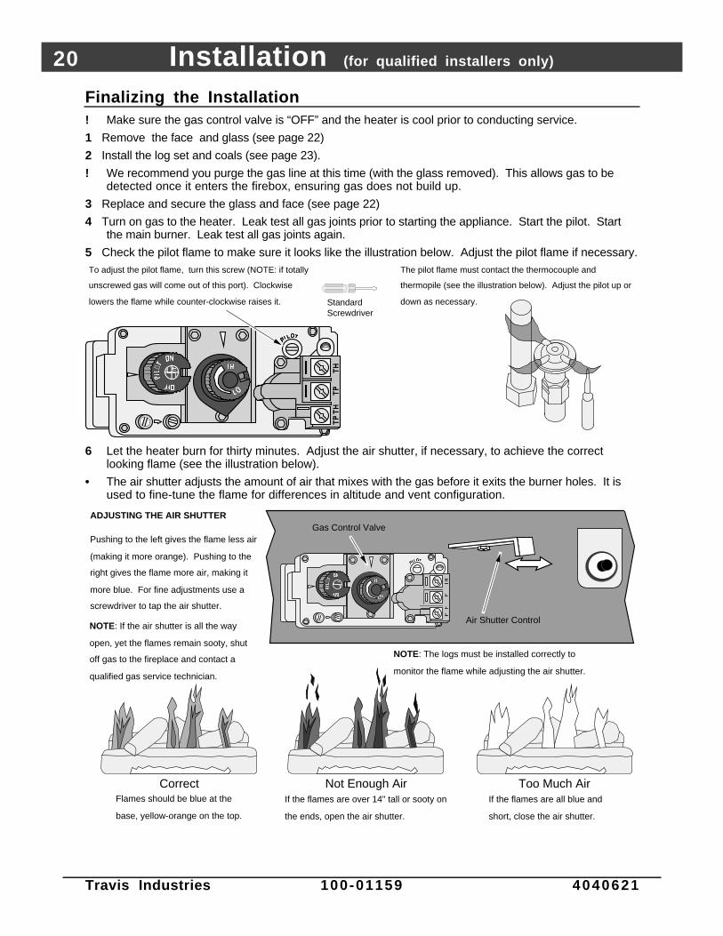
Starting The Pilot Flame
The pilot flame is required to ignite the main burners(it also plays a safety role). It should be left ononce lit. It will stay lit unless the gas control valveis turned to "OFF". However, the pilot will go out ifthe gas is shut off, the propane tank runs out (orlow) or if the stove malfunctions. If the pilot turnsoff frequently, call your dealer for information. Tostart the pilot follow the directions below:
WARNING :When lighting or re-lighting the pilot,the glass must be removed (see page2 2 ) .
a Remove the glass (see page 22 for details).
b Push the gas control knob in slightly and turn it tothe "OFF" position. The knob will not turn from"ON" to "OFF" unless the knob is depressedslightly. Wait five minutes to let any gas thatmay have accumulated inside the fireboxescape. If you smell leaking gas, follow thedirections on the cover "IF YOU SMELL GAS".
c Turn the gas control knob to the "PILOT" positionand press the knob in, this will allow gas to flow tothe pilot light. Press the button on the pilot igniterrepeatedly until you see the pilot light.
WARNING:If the pilot does not light after 15seconds, release the knob and callyour dealer for service. Do not attemptto light pilot until service has beenperformed.
NOTE:You may wish to remove the log set togain a better view of the pilot (see page2 3 ) .
d Keep the gas control knob depressed for 30seconds once it is lit.
e Release the gas control knob. If the pilot goesout, repeat step C. If the pilot refuses to stay lit,call your dealer for service. With the pilot lit,proceed to step “f”.
NOTE:If the gas control knob is turned to“OFF” after the pilot has been lit forseveral seconds, the knob will not turn.This safety feature prevents gas fromentering the firebox.
f Replace the glass.
g Turn the gas control knob counter-clockwise to"ON". The pilot is now lit and the heater can beturned on and off.
?
AAAAAAA
AAAA
30 seconds
PILOT IGNITER
a
b
AAAAAAAA
AAAA
5 minutes
c
d
e
f
g

26 Operation
Travis Industries 100-01159 4040621
Starting the Stove for the First Time
Fumes from the Painted Surfaces CuringBurn the heater at a medium setting for approximately one hour the first time. This will cure thepainted surfaces. Fumes from the paint curing and oil burning off the steel may occur. This isnormal. We recommend you open the window to vent the room.
CondensationWater may appear on the glass each time you start the heater - this is normal.
Blue FlamesThe flames will be blue when first started. After fifteen minutes the flames will turn a more realisticyellow and orange color.
Turning the Stove On and Off
OFF
ROO
M T
EMP
°F°F
SET TE
MP
TIM
ER
MIN
Tim
eSet
Tim
eCan
cel
Au
to
OFF
ON
Use this switch to turn the main burner on and off manually.
After the pilot has been started...
See the instructions included with the remote for details on operation.
For systems with wall thermostats, use this switch to control the temperature (right is hotter, left cooler). Some systems require the on/off switch to be on.
See the instructions included with the remote for changing the battery.
Warning: Do not place combustible items on top or directly in front of the heater, even temporarily.The optional thermostat may start the heater causing a combustible item to ignite.
Note: If the heater turns on and off frequently while using the thermostat, you may want toadjust the flame height down until it produces just enough heat needed.
Adjusting the Flame Height
+ Your stove has an adjustable flame to tailor the look and heat output to your specific needs. It isadjusted by turning the middle dial on the gas control valve.
Flame Height Adjustment Knob
Index Mark
Turn counter-clockwise to adjust the flame higher, clockwise to lower.

Operation 27
Travis Industries 100-01159 4040621
Adjusting the Blower Speed (optional)
The blower helps transfer the heat from the heater into the room. It will not turn on until the heater isup to temperature (approximately 10 minutes after starting). See the illustration below for instructionson adjusting the blower speed.
ON
OFF
ON
OFF
ON
OFF
OFFTurn the dial all the way counter-clockwise until it clicks off.
HIGHThe high position is all the way counter-clockwise, without clicking off.
LOWTurn the dial all the way clockwise.
Normal Operating Sounds
Gas Control Valve
As the gas control valve is turned
on and off you will hear a dull
clicking sound. This is the valve
Blower Snap Disk
This part can produce a clicking sound as
The appliance may creak with change of
temperature -- THIS IS NORMAL.Pilot Flame
The pilot flame,
which remains on,
makes a very slight
"whisper" sound.
Blower
This heater uses a blower to push heated
air into the room. You will hear the sound
of air movement that increases as the
speed is increased.
Extinction Pops
It is not unusual, especially on Propane
(LP) appliances, to experience a "pop"
when the burner is shut off.
Normal Operating Odors
This appliance has several areas that reach high temperatures. Dust or other particles on these areas mayburn and create a burnt-paper smell. This is normal during startup. You may notice the smell is more acuteif the appliance was left idle for a long period.

28 Maintenance (for qualified service personnel only)
Travis Industries 100-01159 4040621
Maintaining Your Stove's AppearancePainted Surfaces
• Painted surfaces should be cleaned with a duster. If scratches occur, lightly sand the area with fine sandpaper.Clean the area and, with the stove cool, apply one or two thin coats of stove paint to the area (mask the area toavoid overspray). Allow the stove to dry, then turn the stove on to cure the paint (1 hour on medium).
Enamel Surfaces• Use only soft cloth and water to clean enamel surfaces. To fix chips in the enamel, follow the directions below:
1) Let the stove cool. Clean the area thoroughly.2) Shake the Travis Enamel Touch-Up thoroughly. Apply to the damaged area.
Glass• Clean the glass with soap and water (do not use abrasive cleaners). To remove the glass, follow the instructions
on page 22.
Yearly Service Procedure! Failure to inspect and maintain the stove may lead to improper combustion and a potentially dangerous situation.
The following procedures must be done by a qualified technician.1 Check the pilot flame. It should touch approximately 3/8" of the top of the thermopile and touch the top of the
thermocouple (see illustration below). If it does not, contact your dealer for service.2 Shut off gas to the stove by turning the gas control knob to "OFF" (see step A under "Starting the Pilot" on page
25). Let the stove cool for 15 minutes. Remove the face and glass (see page 22).3 Remove the log set (NOTE: the logs are very fragile - see page 23). If severely deteriorated, replace.
Check the logs for sooting. A small amount of soot along the bottom of the logs is normal. If excessive sootingis found, the stove will require adjustment. Contact your dealer.
4 Inspect the firebox for the following:• Check the burner for cracked, plugged, or deteriorated holes.• Check the firebox and area around the pilot to make sure there is no warping or damage.• If any problem is found, discontinue use and contact your dealer for service.
Check the burner holes.
Make sure the burner is not
warped or damaged.
Check the walls and ceiling
of the firebox for
deterioration.Thermopile
Pilot Hood
Thermocouple
Before Disassembly - Check the pilot flame.
It should touch the thermocouple and
thermopile.
5 Replace the log set. Replace the glass (if the glass is damaged, replace it). Make sure the gasket along theperimeter of the glass contacts the face of the firebox and forms an air-tight seal. If it does not, re-align orreplace the gasket to insure an air-tight seal. Replace the face.
6 Inspect the area behind the access door. Clean if necessary. Check the gas control valve and the gas lines. Ifany damage is found, discontinue use and contact your dealer for service. Clean the air channels and ducts.
7 Follow the instructions for starting the pilot and turn on the main burner. The flames should be orange/yellow andnot sooty. If the pilot or main burners do not burn correctly, contact your dealer for service
8 Inspect the vent section. Damaged sections should be replaced. Remove any debris or vegetation near thevent termination. Contact your dealer if any sooting or deterioration is found near the vent termination.

Maintenance (for qualified service personnel only) 29
Travis Industries 100-01159 4040621
Troubleshooting Table
Problem: Possible Cause: Don't Call for ServiceUntil You:
Pilot Will Not Light A gas shut off valve is turned off
The gas control knob isn't turned to "PILOT"
The valve control knob isn't pushed in
The igniter wasn't pressed repeatedly
No Propane in Tank
Check all gas shut off valves
See "Starting the Pilot Light" Step C
See "Starting the Pilot Light" Step C
See "Starting the Pilot Light" Step C
Check Tank Level
Main Burners Will NotStart
The pilot light has gone out
The gas control valve is turned to "PILOT" or "OFF"
The ON/OFF switch is turned to "OFF"
The remote control is not working correctly
The thermostat is set too low
See "Starting the Pilot Light"
See "Starting the Pilot Light"
Turn the ON/OFF switch to "ON"
See the remote control instructions
Set thermostat to higher temperature
Remote Control DoesNot Work
The pilot light has gone out
The gas control valve is turned to "PILOT" or "OFF"
ON/OFF switch is turned to "ON" (stove stays on)
The remote is too far away from the stove
The remote control receiver is turned "Off"
One of the two remote control batteries is dead
See "Starting the Pilot Light"
See "Starting the Pilot Light"
Turn the ON/OFF switch to "OFF"
Use the remote closer to the stove
See the remote control instructions
See the remote control instructions
Thermostat Does NotWork
The pilot light has gone out
The gas control valve is turned to "PILOT" or "OFF"
ON/OFF switch is turned to "ON" (stove stays on)
The thermostat is set too low
See "Starting the Pilot Light"
See "Starting the Pilot Light"
Turn the ON/OFF switch to "OFF"
Set thermostat to higher temperature
Optional Blower DoesNot Work
The stove is not getting electricity
The stove is not up to temperature
Check the breaker switch
See "Operating Your Stove"
Pilot Goes Out Once AMonth Or More
The gas supply has been shut off Keep the gas supply turned on
Flames Are Too Blue The stove has just been started
Improper air shutter adjustment
This is normal - see "Starting theStove for the First Time"
Adjust Air Shutter - contact yourdealer
Flames Are Too Short(Under 6")
The flame height may be turned too low Turn the flame height to "HI" -See "Adjusting the Flame Height"
Thin Layer of SootCovers the Glass
The logs or coals are placed incorrectly
Improper air shutter adjustment
See "Log Set Installation & Removal"
Adjust Air Shutter - contact yourdealer

30 Maintenance (for qualified service personnel only)
Travis Industries 100-01159 4040621
How this Stove Works
! This stove was designed with safety as the primary concern. Many of the components inside thisstove are for safety purposes. Therefore, only certified gas service technicians should service thisstove.
What Turns the Main Burners On and Off
This stove uses a millivolt system to control its operation (a millivolt is a very small amount of electricity).The thermopile and thermocouple generate electricity when heated by the pilot flame. This electricityis used to operate the gas valve. Without enough electricity, the gas valve will not turn on. That is whywhen starting the pilot the gas control knob has to be pressed in long enough for the thermocouple toheat up and generate enough electricity. The thermopile provides power for the ON/OFF switch,remote control, or thermostat (see the illustration below). Because the thermopile generates theelectricity needed to turn the stove on and off, this stove can be operated when the power is out(although the blower will not run).
When heated, the thermopile generates electricity (a very small amount measured in "Millivolts").
This electricity is used to operate the main burners. The main burners
are switched on and off using the electricity generated by the thermopile. The ON/OFF switch, remote control, or thermostat control the circuit to the main burner.
ON
OFFMA
IN B
UR
NE
R
What Prevents Gas Buildup
+ This appliance utilizes a high-technology gas valve in conjunction with a pilot flame to ensure no gasbuilds up inside the firebox.
+ The thermocouple (next to the pilot) senses when the pilot flame is lit. If the pilot flame goes out, thisthermocouple no longer generates electricity, causing the gas valve to automatically shut off all gas tothe heater, preventing the pilot from spilling gas into the firebox.
Ceramic GlassThe glass in your heater is the most durable glass available. It has been tested to be extremely resistant to breakage from temperature changes.
Gas ValveThis high-technology valve automatically shuts off all gas if it does not receive a signal from the thermocouple. If any component is damaged or sensing a malfunction, or if the wiring is damaged, it will shut off all gas.
Pilot FlameThe pilot flame is a time-proven component that eliminates the possibility of gas buildup inside the firebox.
ThermocoupleThe thermocouple generates a small amount of electricity. If the pilot flame goes out, the gas valve automatically shuts off all gas.
External Shut Off ValveThis valve is placed on the gas line to shut off gas to the appliance during maintenance procedures.

Maintenance (for qualified service personnel only) 31
Travis Industries 100-01159 4040621
Wiring DiagramCaution: Label all wires prior to disconnection when servicing controls. Wiring errors can cause
improper and dangerous operation.
120 Volt Wiring
Millivolt Wiring (for gas control valve)
Orange
White
Piezo IgniterThermopile
Red
AA
Thermocouple
Copper Co-Axial Wire
Red
Optional Remote Control
Spark Electrode
Pilot Hood
On/Off Switch
Brown
Optional Thermostat
74
109
13
Optional Blower
GreenHot (black)
Common (white)
Ground (green)
Blower Snap Disk
Power In Molex
Connector
Po
wer
Su
pp
ly
Ground (attached to stove)
White
Black
1
35
7
24
68
9
1211
10
36
White
9
25
Black
Remote Control Molex
Connector8
11
Blue
Blue
Optional Regulator Solenoid
1
4
Black
Black
7
Black
Black
10
Red
Brown
Rheostat
Gas Control Valve
Replacement Parts ListCaution: Use only Travis Industries replacement parts. Do not use substitute materials.
Air Shutter 93006513 Log Set 93006530Air Shutter Assembly 93006512 Orifice, Gas, .0625, 98900717Air Shutter Control Rod 93006514 Orifice, Gas, #37 98900713Base Black Paint 93008175 Orifice, Pilot, .016 (LP 91001506Blower, Convection 98900755A Orifice, Pilot, .021 (NG 91001505Blower Mounting Grommets w Spacers 93005017 Piezo Igniter 98900751Burner Assembly 93006510 Pilot Assembly Gasket 93006022Burner Mixing Tube 93006511 Pilot Assembly, LP 93006021Control Valve (NG) 93006506 Pilot Assembly, NG 93006020Control Valve (LP) 93006507 Pilot Tube 91001508Conversion Parts, LP 93006503 Power Cord w Connector 99300656Conversion Parts, NG 93006502 Pressure Relief Doors 91001542Enamel Touch-Up, Cameo 99500122 Regulator, (NG) 93006500Enamel Touch-Up, Fyrestone 99500123 Regulator, (LP) 93006501Enamel Touch-Up, Oxford Brown 100-02406 Rheostat 93006504Gas, Flex-pipe, 3/8 x 10 91002560 Snap Disk, 120 Degree 98900720Glass Latch Assembly 93006521 Stove Pack, Cameo 98900483Glass w/Frame 93006520 Stove Pack, Fyrestone 98900484Knob for Rheostat 99300657 Stove Pack, New Iron 98900482Latch Tool for Glass Frame 93006041 Switch, On/Off 98900747Log, Left 93006533 Thermocouple 93006518Log, Left Twig 93006535 Thermopile 98900752Log, Rear 93006531 Wiring Harness 93006505Log, Right 93006532Log, Right Twig 93006534

32 Safety Label
Travis Industries 100-01159 4040621
The safety (listing) label is on the back of the stove. A copy of the safety label is shown below.
BerkshireVented Gas
Fireplace HeaterReport No. 028-S-28-5
Certified for USA & CanadaTested to: ANSI Z21.88b-1999/CSA 2.33-M99 “Vented Gas Fireplace Heater”, CAN/CGA 2.17-M91 “Gas-Fired Appliances for use at High Altitudes”,and UL307b-1995 “Gas Burning Heating Appliances for Manufactured Homes”Must be installed in accordance with the manufacturer’s installation instructions and all local codes, if any; if not, follow current ANSI Z223.1,NFPA 54 and CGA B149. This vented gas fireplace heater is equipped at the factory for use with natural gas. If conversion to propane (LP) fuel isdesired, the optional factory conversion kit must be used. This appliance uses a millivolt-type control system consisting of a gas control valve/reg-ulator, a standing pilot burner assembly, a thermopile, a piezo ignitor, and the ON/OFF switch. THIS UNIT DOES NOT REQUIRE 110 VOLT POWERTO OPERATE. All exhaust gases must be vented outside the structure of the living-area. Combustion air is drawn from outside the living-areastructure. This appliance is only for use with the type of gas indicated on the rating plate and may be installed in an aftermarket, permanentlylocated, manufactured (mobile) home where not prohibited by local codes. See owner’s manual for details. This appliance is not convertible foruse with other gases, unless a certified kit is used. May be installed in a bedroom - in Canada install with a listed thermostat, in the USA installper local codes.This vented gas fireplace heater is not for use with air filters.WARNINGS:Improper installation, adjustment, alteration, service or maintenance can cause injury or property damage. Refer to the information in theowner’s and installation manual provided with this appliance. For assistance or additional information consult a qualified installer, serviceagency or the gas supplier.Installation and repair should be performed by a qualified service person. The appliance should be inspected before use and at least annuallyby a qualified service person. More frequent cleaning may be required where excessive lint from material like carpeting and bedding is present.The control compartment, the burner compartment and all circulating air passageways of the appliance must be kept clean and clear at alltimes. See installation instructions accompanying appliance.Due to high temperatures, the appliance should be located out of traffic and away from furniture and draperies.This appliance must not be connected to a chimney flue servicing a separate solid fuel burning appliance.Operation of this appliance when not connected to a properly installed and maintained venting system or tampering with the blocked ventshutoff system can result in carbon monoxide (CO) poisoning and possible death.Vented gas fireplace heater - Not for use with solid fuel.Children and adults should be alerted to the hazards of high surface temperature and should stay away to avoid flesh burns or clothing ignition.Young children should be carefully supervised at all times when they are in the same room as the appliance.CAUTION:Do not operate this appliance with glass removed, cracked or broken. Replacement of the panel(s) should be done by a licensed or qualifiedservice person.Hot while in operation. Do not touch. Keep children, clothing, furniture, gasoline and other liquids having flammable vapors away.Risk of electrical shock. Switch the household breaker off or remove fuse before servicing unit.Use Simpson DURA-VENT direct vent system (Model GS) to vent this appliance to the exterior (direct discharge only without duct connection).
10850 117th Pl. N.E. Kirkland, WA 98033
Minimum Clearances to CombustiblesStove Top to Sidewall ......................... 10” Alcove Min. Height.................................... 58”Stove Top to Backwall ........................ 5” Alcove Max. Depth.................................... 45”Stove Top to Cornerwall..................... 5” Alcove Min Width...................................... 46-3/4”Glass Front of Unit.............................. 36”
L.P. N.G. L.P. N.G.Input Rate on “HI” (BTU/Hr)* . . . . . . 31,000 31,000 Minimum Inlet Pressure (inches W.C.) . . . . . . . . 11” 5.5”Input Rate on “LO” (BTU/Hr)* . . . . . 23,000 24,900 Maximum Inlet Pressure (inches W.C.) . . . . . . . . 13” 7”
Manifold Pressure on “HI” (inches W.C.) . . . . . . 10” 3.5”This appliance is equipped only for altitudes 0-2000 ft. (0-610 m) in USA; in Canada, 0-4500 ft. (0-1370 m).Electrical Rating: 115v, 1.5 Amps, 60 Hz
Manufacture 2000 Jan. Apr. Jul. Oct.Date: 2001 Feb. May Aug. Nov.
2002 Mar. Jun. Sep. Dec. 0371

Warranty 33
Travis Industries 100-01159 4040621
To register your TRAVIS INDUSTRIES, INC. 7 Year Warranty, complete the enclosed warranty card and mail it within ten (10) days of the appliancepurchase date to: TRAVIS INDUSTRIES, INC., 4800 Harbour Pointe Blvd. SW, Mukilteo, WA 98275. TRAVIS INDUSTRIES, INC. warrants this gasappliance (appliance is defined as the equipment manufactured by Travis Industries, Inc.) to be defect-free in material and workmanship to the originalpurchaser from the date of purchase as follows:
Check with your dealer in advance for any costs to you when arranging a warranty call.Mileage or service charges are not covered by this warranty. This charge can vary from store to store.
Years 1 & 2 - COVERAGE: PARTS & LABORBurner Assembly:Burner Pan, Mixing Tube, Air Shutter Assembly, MainBurner Orifice
Firebox Assembly:Adjustable Air Restrictor, Pressure Relief Mechanisms(direct vents only), Glass Attachment Mechanism
Gas Control AssemblyAdjustable control valve, millivolt wiring and connectors(located within the metal heater structure), thermopile,thermocouple, pilot hood, orifices, pilot gas line, piezoignitor
Cast Iron ShellCast Sides, Front, Top, Bottom, & Legs
Ceramic GlassGlass (breakage from thermal shock)
Ceramic LogsLog Set
Electrical Assembly : Blower, wiring harness, snap discs, rheostat speed control
Convection Heat Exchanger
Re-Installation AllowanceIn cases where heater must be removed from home forrepairs, a partial cost of re-installation is covered (pre-authorization required)
One-Way Freight AllowanceOne-way freight allowance on pre-authorized repair done atfactory is covered.
Exclusions: Paint, Gasketing, Enamel Finish, Stone Inserts
Years 3 THROUGH 5 - COVERAGE: PARTS & LABORFirebox Assembly:Adjustable Air Restrictor, Pressure ReliefMechanisms (direct vents only), GlassAttachment Mechanism
One-Way Freight AllowanceOne-way freight allowance on pre-authorized repair done atfactory is covered.
Cast Iron ShellCast Sides, Front, Top, Bottom, & Legs
Convection Heat Exchanger
Exclusions: Paint, Gasketing, Enamel Finish, Stone Inserts, Burner Assembly, Electrical Assembly, Gas Control Assembly, Ceramic Glass,Ceramic Logs, Re-Installation Allowance
Years 6 & 7 - COVERAGE: PARTS ONLYFirebox Assembly:Adjustable Air Restrictor, Pressure Relief Mechanisms, Glass Attachment Mechanism
Cast Iron ShellCast Sides, Front, Top, Bottom, & Legs
Exclusions: Paint, Gasketing, Enamel Finish, Stone Inserts, Burner Assembly, Electrical Assembly, Gas Control Assembly, Ceramic Glass,Ceramic Logs, Convection Heat Exchanger, Re-Installation Allowance, One-Way Freight Allowance, Labor
CONDITIONS & EXCLUSIONS1. This new gas appliance must be installed by a qualified gas appliance technician. It must be installed, operated, and maintained at all times in accordance with the instructions in the Owner’s
Manual. Any alteration, willful abuse, accident, neglect, or misuse of the product shall nullify this warranty.2. This warranty is nontransferable, and is made to the ORIGINAL purchaser, provided that the purchase was made through an authorized TRAVIS dealer.3. Discoloration and some minor expansion, contraction, or movement of certain parts and resulting noise, is normal and not a defect and, therefore, not covered under warranty. The installer
must ensure the appliance is burning as per the rating tag at the time of installation. Over-firing (operation above the listed BTU rate) of this appliance can cause serious damage and will nullifythis warranty.
4. The warranty, as outlined within this document, does not apply to the chimney components or other Non-Travis accessories used in conjunction with the installation of this product. If in doubt asto the extent of this warranty, contact your authorized TRAVIS retailer before installation.
5. Travis Industries will not be responsible for inadequate performance caused by environmental conditions such as nearby trees, buildings, roof tops, wind, hills or mountains or negative pressureor other influences from mechanical systems such as furnaces, fans, clothes dryers, etc.
6. This Warranty is void if:a. The unit has been operated in atmospheres contaminated by chlorine, fluorine or other damaging chemicals.b. The unit is subject to submersion in water or prolonged periods of dampness or condensation.c. Any damage to the unit, combustion chamber, heat exchanger or other components due to water, or weather damage which is the result of, but not limited to, improper chimney/venting
installation.7. Exclusions to this 7 Year Warranty include: injury, loss of use, damage, failure to function due to accident, negligence, misuse, improper installation, alteration or adjustment of the
manufacturer's settings of components, lack of proper and regular maintenance, damage incurred while the appliance is in transit, alteration, or act of God.8. This 7 Year warranty excludes damage caused by normal wear and tear, such as paint discoloration or chipping, worn or torn gasketing, corroded or cracked logs, embers, etc. Also excluded is
damage to the unit caused by abuse, improper installation, modification of the unit, drilling of the orifices, or the use of fuel other than that for which the unit is configured. Units are shipped fornatural gas and must be converted to propane using the included conversion kit. Confirm fuel configuration with your installer.
9. Damage to gold, nickel, or brass surfaces caused by fingerprints, scratches, melted items, or other external sources left on the surface is not covered in this warranty. Damage from the useof cleaners other than denatured alcohol on gold or nickel is not covered in this warranty. Damage from the use of abrasive cleaners on brass is not covered in this warranty.
10. TRAVIS INDUSTRIES, INC. is free of liability for any damages caused by the appliance, as well as inconvenience expenses and materials. Incidental or consequential damages are not coveredby this warranty. In some states, the exclusion of incidental or consequential damage may not apply.
11. This warranty does not cover any loss or damage incurred by the use or removal of any component or apparatus to or from the gas appliance without the express written permission of TRAVISINDUSTRIES, INC. and bearing a TRAVIS INDUSTRIES, INC. label of approval.
12. Any statement or representation of TRAVIS products and their performance contained in TRAVIS advertising, packaging literature, or printed material is not part of this 7 year warranty.13. This warranty is automatically voided if the appliance’s serial number has been removed or altered in any way. If the appliance is used for commercial purposes, it is excluded from this warranty.14. No dealer, distributor, or similar person has the authority to represent or warrant TRAVIS products beyond the terms contained within this warranty. TRAVIS INDUSTRIES, INC. assumes no
liability for such warranties or representations.15. Travis Industries will not cover the cost of the removal or re-installation of hearths, facing, mantels, venting or other components.16. If for any reason any section of this warranty is declared invalid, the balance of the warranty remains in effect and all other clauses shall remain in effect.17. THIS 7 YEAR WARRANTY IS THE ONLY WARRANTY SUPPLIED BY TRAVIS INDUSTRIES, INC., THE MANUFACTURER OF THE APPLIANCE. ALL OTHER WARRANTIES,
WHETHER EXPRESS OR IMPLIED, ARE HEREBY EXPRESSLY DISCLAIMED AND PURCHASER’S RECOURSE IS EXPRESSLY LIMITED TO THE WARRANTIES SET FORTHHEREIN.
IF WARRANTY SERVICE IS NEEDED:1. If you discover a problem that you believe is covered by this warranty, you MUST REPORT it to your TRAVIS dealer WITHIN 30 DAYS, giving them proof of purchase, the purchase date,
and the model name and serial number.2. Travis Industries has the option of either repairing or replacing the defective component.3. If your dealer is unable to repair your appliance’s defect, he may process a warranty claim through TRAVIS INDUSTRIES, INC., including the name of the dealership where you purchased the
appliance, a copy of your receipt showing the date of the appliance’s purchase, and the serial number on your appliance. At that time, you may be asked to ship your appliance, freight chargesprepaid, to TRAVIS INDUSTRIES, INC. TRAVIS INDUSTRIES, INC., at its option, will repair or replace, free of charge, your TRAVIS appliance if it is found to be defective in material orworkmanship within the time frame stated within this 7 year warranty. TRAVIS INDUSTRIES, INC. will return your appliance, freight charges (years 1 to 5) prepaid by TRAVIS INDUSTRIES,INC., to your regional distributor, or dealership.
4. Check with your dealer in advance for any costs to you when arranging a warranty call. Mileage or service charges are not covered by this warranty. This charge can vary from store to store.
34 Optional Equipment (for qualified installers only)
Travis Industries 100-01159 4040621
Optional Accessories
• Double Doors, New Iron 99300490
• Double Doors, Oxford Brown 99300491
• Double Doors, Taupe 99300492
• Grill Cover, FyreStone 99600205
• Grill Cover, New Iron 99600207
• Grill Cover, Oxford Brown 99600208
• Grill Cover, Taupe 99600209
• Hearth Pad, Granite 99600211
• Hearth Pad, Travertine 99600213
• Hearth Pad, Soapstone 99600210
• Remote Thermostat 99300653
• Remote Thermostat - Modulating 99300670 & 71 (NG or LP)
• Side & Top Panels, Cast Linenfold - Oxford Brown 99600226
• Side & Top Panels, Cast Linenfold - Taupe 99600227
• Side & Top Panels, Granite 99600200
• Side & Top Panels, Soapstone 99600201
• Side & Top Panels, Travertine 99600217
• Steamer, Soapstone 99600216
• Thermostat, Wall 99300560
• Warming Stone, Granite 99600215

Optional Equipment (for qualified installers only) 35
Travis Industries 100-01159 4040621
LP Conversion Instructions
Install the conversion kit prior to installing the gas line to ensure proper gas use.
1 Remove the face and glass (see page 22). Remove the log set (if installed - page 23)
2 Remove the burner (see illustration below).
AAAAAAAAAA
When Installing, make sure the burner rests
on this ledge with the center air channel fitting
over this tab.
Reach into the firebox and
lift the burner upwards.AAAAAAAAAA
Pull the burner forward, out
of the firebox. This tube on the burner
inserts into this tube on the
mixing tube.
Do not lift burner out by the
pins.
AAAAAAAA
When Installing, make sure the burner rests
on the two ledges at the sides of the firebox.
Older Model Burners
Older models (Berkshires s.n. 857740
or less - Prairies s.n. 801307 or less)
utilize a different burner and mounting
method (see illustration to right). If
replacing the burner, refer to the
instructions included with the
replacement burner for installation
instructions.

36 Optional Equipment (for qualified installers only)
Travis Industries 100-01159 4040621
3 Follow the directions below to remove the natural gas orifice. Apply thread sealant to the LP orifice ( ithas ".062" stamped on it) and tighten in place with a 1/2" open end wrench. Replace and secure themixing tube.
AAAAAAA
1/2" Wrench
Use a 1/2” open end wrench to
unscrew the burner orifice.
NOTE:
Screw the LP orifice in
so the orifice shoulder
protrudes 5/16”
(indicating full insertion).
37.0
62
The new LP orifice
has “.062” stamped
on it.
The old NG
orifice has “37”
stamped on it.
Apply thread
sealant to the
new orifice and
install.
5/16”
Remove the four screws
holding the mixing tube in
place.
AAAAAA
Remove the mixing tube
from the air shutter by
sliding it to the left.
1/4" Nutdriver
Air Shutter
a
b
Slide the air shutter to the fully
open position (see page 19).
Manifold
Burner Orifice
c
d e
4 Remove the pilot orifice following the instructions below. Replace with the propane pilot orifice. Thepropane conversion kit includes pilot orifice with "35" stamped on it. Replace burner pan.
Lift the pilot hood
off the pilot
assembly.
5/32" Hex
Use a hex wrench to
unscrew the orifice.
Remove the orifice and replace with the LP orifice. Screw the
orifice all the way in and replace the pilot hood.
LP (Propane) Orifice
Orifice Identification:
NG (Natural Gas) Orifice
35
62
35
a
b
c
NOTE: when re-attaching,
this pin lines up with the
notch in the pilot hood.
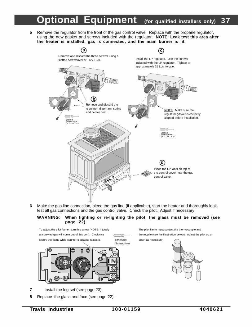
Optional Equipment (for qualified installers only) 37
Travis Industries 100-01159 4040621
5 Remove the regulator from the front of the gas control valve. Replace with the propane regulator,using the new gasket and screws included with the regulator. NOTE: Leak test this area afterthe heater is installed, gas is connected, and the main burner is lit.
Place the LP label on top of the control cover near the gas control valve.
d
Remove and discard the three screws using a slotted screwdriver of Torx T-20.
NOTE: Make sure the regulator gasket is correctly aligned before installation.
Remove and discard the regulator, diaphram, spring and center post.
a
b
Slotted Screwdriver(or T-20 Torx)
Install the LP regulator. Use the screws included with the LP regulator. Tighten to approximately 25 Lbs. torque.
c
Slotted Screwdriver(or T-20 Torx)
6 Make the gas line connection, bleed the gas line (if applicable), start the heater and thoroughly leak-test all gas connections and the gas control valve. Check the pilot. Adjust if necessary.
WARNING: When lighting or re-lighting the pilot, the glass must be removed (seepage 22).
Standard Screwdriver
The pilot flame must contact the thermocouple and
thermopile (see the illustration below). Adjust the pilot up or
down as necessary.
To adjust the pilot flame, turn this screw (NOTE: if totally
unscrewed gas will come out of this port). Clockwise
lowers the flame while counter-clockwise raises it.
7 Install the log set (see page 23).
8 Replace the glass and face (see page 22).

38 Optional Equipment (for qualified installers only)
Travis Industries 100-01159 4040621
Blower (part # 99000153)
WARNING: Turn the gas control valve to off and make sure the appliance has fully cooled prior toconducting service.
1 Attach the two black wires at the rear right of the stove to the thermodisk (orientation does not matter).Then slide the thermodisk into the holder underneath the burner pan.
Snap Disk Bracket
(attached to stove)
Snap Disk
Snap Disk Wires on Wiring Harness
(Black - orientation does not matter)
Back of
Stove
2 Place the blower near the rear of the stove. Attach the wiring in grommets following the directionsbelow.
Slide the rubber grommets (with
spacers inserted inside) onto the
fan mounting bracket.
Attach the black and white wires
labeled “Blower” to the blower
(orientation does not matter).
Attach the molex connector.
DO NOT PLUG THE STOVE
IN UNTIL INSTALLATION IS
COMPLETE.
Back of
Stove1/4" Nutdriver
Remove one of the screws holding
the mounting bracket in place. Insert
the screw through the eyelet on the
green ground wire and replace.
a
b
c
dAttach the two wires leading
from the control box to the two
block wires labeled “Rheostat”.
e
Route the wires labeled “Valve
on/off” and “Solenoid” under
the burner pan to a location
near the gas control valve.
f

Optional Equipment (for qualified installers only) 39
Travis Industries 100-01159 4040621
3 Slide the left side of the blower mounting bracket over the grommets on the left mounting bracketattached to the stove (see the illustration below). Then insert the stud plate through the right sidegrommets and through the right mounting bracket on the stove. Secure the stud plate with theincluded washers and nuts
Nut
Stud Plate
Washer11/32” Socket
Make sure the bracket
slides into the groove on
the rubber grommets.
Left Mounting
Bracket (on stove)
Rubber
GrommetBlower Mounting
Bracket
Right Mounting
Bracket (on stove)
Back of
Stove
Blower Mounting Bracket
Stud Plate
Blower Mounting Bracket
4 Make sure all of the wiring is placed away from the blower impeller and the bottom of the burner. Uselock ties, if necessary, to ensure no wires are damaged.
5 Open the control cover following the directions below. Remove the button plug and install therheostat.
Back of Stove
Loosen the two screws holding the control box in place. This allows access to the back of the control box.a
b
c
Remove the button plug from the control box.
Attach the rheostat wires to the two quick connects inside the control box (orientation does not matter).
Control Box
eRheostat
1/2" Wrench
NOTE: this tab fits into the hole on the mounting bracket.
Attach the rheostat to the control panel with the included nut and star washer.
Attach the knob.
NOTE: make sure the fiberglass heat shield is in place when re-attaching the control box.
Phillips Screwdriver
6 Plug the blower in. Let the heater achieve operating temperature and test blower operation.

40 Optional Equipment (for qualified installers only)
Travis Industries 100-01159 4040621
Fireback (Part # 99600220)
WARNING: Turn the gas control valve to off and make sure the appliance has fully cooled prior toconducting service.
1 Before installing, remoe the face, glass, and logs. Install the firebacks following the directions below.
Remove the screws at the top of the firebox walls.
5/16" Nutdriver
a
cPlace the side firebacks on the ledges at each side of the firebox.
Fireback Clip
Side Fireback
b
Place the rear fireback (it rests on the two ledges on each side of the firebox). The side firebacks keep the rear fireback from tilting forward.
Secure the firebacks with the included clips and screws (removed in step “a”).
d
Rear Fireback

Optional Equipment (for qualified installers only) 41
Travis Industries 100-01159 4040621
Stone or Cast Insert Installation
• Granite 99600200 • Soap Stone 99600201 • Marble 99600202 • Travertine 99600217• FyreStone 99600204 • Oxford Brown 99600226 • Taupe 99600227
WARNING: Turn the gas control valve to off and make sure the appliance hasfully cooled prior to conducting service.
1. Remove the face following the directions below.
Use the latch tool to open the face
latches on both sides.
With the door latches disengaged,
the face can be removed.
NOTE:
Enameled
parts can be
easily
damaged by
mis-handling.
2. Remove the stove top following the directions below.
Phillips
Screwdriver
On Older Units:
Loosen (or remove) the
screw and locking tab
under the stove top.
Use both hands to pull the
stove top forward, rotate it
up, then lift it off the stove.

42 Optional Equipment (for qualified installers only)
Travis Industries 100-01159 4040621
3. Loosen the front and back bolts holding the side insert retainers following thedirections below.
3/8" Wrench
Side Insert Retainer
Loosen the bolts at the
front of the cast sides a
couple of turns. Then
rotate the retainer up.NOTE: on the Sheffield,
remove the side clips first.
4. Loosen the bolts holding the retainers in place several turns (see the illustrationbelow). Slide the side inserts into place. Replace the side insert retainers andtighten the bolts (do not over-tighten – the side inserts brackets need only be tightenough to prevent the side inserts from rattling).
AAAAAAAAAAAAAAAAAAAAAAAAAAAAAAAAAAAAAAAAAAAAAAAAAAAAAAAAAAAAAAAAAA
AAAAAAAAAAAAAAAAAAAAAAAAAAAAAAAAAAAAAAAAAAAAAAAAAAAAAAA
AAAAAAAAAAAAAAAAAAAAAAAAAAAAAAAAAAAAAAAAAAAAAAAAAAAAAAAAAAAAAAAAAAAAAAAA
AAAAAAAAAAAAAAAAAAAAAAAAAAAAAAAAAAAAAAAAAAAAAAAAAAAAAAAAAAAAAAAAAA
Use both hands to guide the side
stones into place.
NOTE: Loosen this bolt several
turns before installing.
WARNING: The stones are fragile
and scratch easily.
3/8" Wrench
Side Insert Retainer
(rotate out of the way if necessary)
Rear View

Optional Equipment (for qualified installers only) 43
Travis Industries 100-01159 4040621
5. Place the stove top upside down on a smooth, non-scratching surface. Install thestone inserts into the stove top following the directions below. Replace the stovetop and face to finalize the installation.
Note: On the Fyrestone the clips and screws are shipped with the stove in the owner’s pack.Note : The granite stones may be slightly thin. This leads to the clips not securing the stones in
place. Before installing, use a hammer or pliers to slightly bend the clips downwards. This willhold the granite tightly against the stove top.
AAAAAAAAAAAAAAAAAAAAAAAAAAAAAAAAAAAAAAAAAAAAA
AAAAAAAAAAAAAAAAAAAAAAAAAAAAAAAAAAAAAAAAAAAAA
AAAAAAAAAAAAAAAAAAAAAAAAAAAAAAAAAAAAAAAAAAAAA
AAAAAAAAAAAAAAAAAAAAAAAAAAAAAAAAAAAAAAAAAAAAAAAAAAAAAA
Phillips Screwdriver
Place the stone inserts into the indents on the stove top. Attach with the clips and screws.
NOTE: slide the inserts inwards as far as possible to prevent them from striking the sides of the cast body.
These clips are for the linenfold, marble, & granite inserts.
These clips are for the soapstone inserts.

44 Installation Addenda
Travis Industries 100-01159 4040621
ADDENDUM #1 Class A Chimney Conversion KitSimpson Duravent provides a conversion kit for those wishing to use an existing wood stove chimney to ventthis direct vent stove. The illustration below gives an overview of this type of installation. See the instructionsincluded with the kit for details.
! Do not exceed the maximum vertical rise (see the section "Approved Vent Configurations" starting on page 11)allowable. Remember to set the restrictor position to the correct position (based upon the vertical rise height -see the chart on page 11).
! The conversion kit does not work on interior masonry chimneys.
Chimney Conversion Kit A (# 931)Metalbestos 6" I.D.Security Chimneys 6" I.D.Jackes-Evans 6" I.D.Hart & Cooley 6" I.D.Pro-Jet 6" I.D.Chimney Conversion Kit B (# 932)Simpson Dura-Vent 6" I.D.Air-Jet 6" I.D.Metal-Fab 6" and 7" I.D.Amer. Metals 6" & 7" I.D.Metalbestos 7" and 8" I.D.Jackes-Evans 7" and 8" I.D.Hart & Cooley 7" and 8" I.D.Pro-Jet 7" and 8" I.D.Security Chimneys 8" I.D.Chimney Conversion Kit C (# 933)Simpson Dura-Vent 7" and 8" I.D.American Metals 8" I.D.Air-Jet 8" I.D.Metal-Fab 8" I.D.American Metals 8" I.D.Each Kit Contains: Retro ConnectorRetro Vertical TopAdditional Required Equipment:4" Flex (#711 or U.L. 1777)Termination (#991)Co-Axial Sections
Type A Chimney
Simpson Duravent Direct Vent Pipe Sections(use adjustable section)
Screw the Retro Vertical Top to the Flex Pipe
Retro Vertical Top (screw to chimney)
Screw the Retro Connector to the Flex Pipe
Retro Connector(screw to chimney)
4" (100 mm) Aluminum Flex Pipe
Cut the Flex Pipe to the chimney height plus 3" (75 mm)

Installation Addenda 45
Travis Industries 100-01159 4040621
ADDENDUM #2 Interior Masonry Chimney Conversions
• Follow the requirements and use the equipment listed in the illustration below to install this applianceinto an interior masonry chimney.
• Maximum vertical rise is 40'
• Minimum vertical rise is 10'
• See the chart on page 13 for determining the correct restrictor position.NOTE: these restrictor positions are based upon lab tests. The ideal restrictor position may varyslightly.
AAAAA
AAA
AAAAAAAAAAAAAAAAA
AAAAAAAAAAAAAAAAAAAAAA
AAAAAAAA
AAAAA
AAAA
AAAAA
AAAA
AAAAAAAA
AAAAAAAAAA
AAAAAAAAAAAAAAAAA
AAAAAAAA
The entire chimney system must be air-tight. Make sure to seal the flashing, clean-out, and thimble connection, and to inspect the chimney.
#711 Flex Liner (4” dia.)(or other UL 1777 Gas Liner)
Co-Axial Straight Lengths
#991 High Wind Termination
#990 90° Elbow
Flashing (included in #934 Masonry Conversion Kit
Make sure the coaxial pipe maintains a 1” clearance to any combustible. The vent must be sealed air-tight.
High-Temp. Silicone
Connector with Cover (included in #934 Masonry Conversion Kit)
Interior Masonry Chimney
Standard Masonry Fireplace
Connector (included in #934 Masonry Conversion Kit) secured and sealed to block-off plate.
AA
AAAAAAAA
AAAAAAAAAAAAAA AAAAAAAAAAAAAAAAAAAAAAAAAAAAAAAAAAA
AAAAAAAAAAAAAAAAAAAAAAAAAAAAAAAAAAAAAAAAAA
AAAAAAAAAAAAAAAA
AAAAAAAAAA
AAAAAAAAAA
AAAAAA
AAAA
AAAAAA
AAAAAA
AAAA
AA
Flashing (included in #934 Masonry Conversion Kit)
#991 High Wind Termination
#711 Flex Liner (4” dia.)(or other UL 1777 Gas Liner)
The entire chimney system must be air-tight. Seal the connector cover and inspect the chimney.
Make sure the coaxial pipe maintains a 1” clearance to any combustible. The vent must be sealed air-tight.
High-Temp.
Silicone

46 Index
Travis Industries 100-01159 4040621
Approved Vent Configurations..........................12-17Adjusting the Blower Speed..............................26Adjusting the Flame Height ...............................25Air Shutter Adjustment......................................19Altitude Considerations.....................................10Blower Control..................................................26BTU Input.........................................................5BTU Output......................................................5Cap (see vent termination).................................18Chimney Cap (see vent termination)...................18Clearances.......................................................7Condensation on Glass.....................................25Corner Installation.............................................7Dimensions......................................................5Door Removal...................................................21Dura-Vent (part numbers)..................................10Elbows.............................................................11Face Removal...................................................21Finalizing the Installation....................................19Floor Protection ...............................................8Fuel .................................................................2Gas Control Valve (Location)..............................23Gas Inlet Pressure.............................................9Gas Line Connection ........................................9Gas Line Install..................................................9Gas Smell .................................See Inst. on CoverGlass Installation and Removal ...........................21Hearth Requirements........................................8Heating Specifications ......................................5Horizontal Vent Termination Requirements ........18How this Stove Works .......................................29
Installation Options ...........................................5Items Required for Installation............................6Leaking Gas .............................See Inst. on CoverListing Information ............................................31Location of Controls..........................................23Log Set Installation and Removal .......................22Maintenance ....................................................27Measuring Vent Lengths...................................11Noise (see Normal Operating Sounds) ...............26Normal Operating Sounds.................................26Packing List......................................................6Pilot Flame Inspection.......................................23Piping Installation (see Gas Line Install)...............9Restrictor Position ............................................11Safety Label.....................................................31Safety Precautions ...........................................2Starting The Pilot ..............................................24Starting the Stove for the First Time ...................25Thermostat Operation.......................................25Turning the Stove On and Off............................25Vent Length (see “Vent Config.”) ......................11Vent Part Numbers ...........................................10Vent Requirements ..........................................10Vertical Vent Termination Requirements ............18Warnings..........................................................2Warranty...........................................................32Water on Glass (see Condensation) ...................25Weight (225 Lbs.) .............................................5What Prevents Gas Buildup...............................25What Turns the Main Burners On and Off............25Wiring Diagram..................................................30Yearly Service Procedure..................................27


![› en › techinfo › archive › manual › AX...History of Amendments [For version 11.10] Summary of amendments In addition to the above change, minor editorial corrections have](https://static.fdocuments.net/doc/165x107/5f29323af8196d361c3e8aa5/a-en-a-techinfo-a-archive-a-manual-a-ax-history-of-amendments-for.jpg)