BER and Subjective Evaluation for DVB-T/H Receiver · PDF fileBER and Subjective Evaluation...
29
BER and Subjective Evaluation for DVB-T/H Receiver Test Application Note An optimized solution for pre-production R&D and manufacturing
Transcript of BER and Subjective Evaluation for DVB-T/H Receiver · PDF fileBER and Subjective Evaluation...

BER and Subjective Evaluationfor DVB-T/H Receiver Test
Application Note
An optimized solution for pre-production R&D and manufacturing

2
Introduction and Abbreviations ...........................................................................................3
1. Overview ............................................................................................................................4
2. About DVB-T and DVB-H Technologies ....................................................................5
2.1 DVB-T ......................................................................................................................5
2.2 DVB-H .....................................................................................................................5
2.3 Compatibility between DVB-T and DVB-H ....................................................5
3. Receiver Test: BER vs. Subjective Video Evaluation ..............................................6
3.1 Degradation criteria and resynchronization ..................................................6
3.2 BER test point in DVB-T/H system .................................................................6
3.3 BER test with user defi ned patterns or PN23 ..............................................7
3.3.1 PHY stream layer measurements ......................................................7
3.3.2 MPEG-2 TS measurements .................................................................9
3.4 Subjective evaluation and seamless TS video playback ............................9
3.4.1 Compile a TS stream to match the physical channel ...................9
3.4.2 Real environment simulation: short video fi le with
real-time AWGN and fading ..............................................................10
3.5 Relationship between objective and subjective video evaluation ........10
4. General Test Diagram Introduction...........................................................................11
4.1 N7623B Signal Studio for digital video software .......................................11
4.2 Signal generator platforms ..............................................................................12
4.2.1 N5182A MXG and N5162A MXG ATE vector signal
generators .............................................................................................12
4.2.2 E4438C ESG vector signal generator ..............................................12
4.2.3 E8267D PSG vector signal generator .............................................13
4.3 N5115B Baseband Studio for fading and N5102A digital interface ......13
5. MBRAI Receiver Test Case Analysis .......................................................................14
5.1 Receiver minimum and maximum input signal levels ...............................14
5.2 Channel simulation: fading and AWGN ........................................................15
5.3 Interference and immunity tests ....................................................................16
5.4 GSM900 TX signal blocking test ....................................................................17
6. Examples of Typical DVB-T/H Receiver Tests .......................................................18
6.1 Receiver minimum and maximum input signal levels ...............................19
6.2 C/N performance ...............................................................................................20
6.3 Immunity to analog and/or digital signals in adjacent channels ...........21
6.4 Guard interval utilization: echoes within the guard Interval ...................22
6.5 Mobile SFN channel test .................................................................................24
7. Receiver Production Recommendation ...................................................................26
7.1 Application programming interface (API) ....................................................26
7.2 Recommended MBRAI test items .................................................................27
Reference ................................................................................................................................28
Table of Contents

3
Agilent Technologies N7623B Signal Studio for digital video is software
designed to simulate multiple formats of video broadcast ARB waveforms
including: DVB-T/H/C/S, ISDB-T/TSB/TB, DTMB, ATSC, T-DMB, S-DMB,
CMMB, and J.83 Annex A/B/C. Agilent’s PSG/ESG/MXG vector signal
generators are optimized for all in one mobile receiver test including video,
cellular communication and wireless connection applications. This application
notes focuses on DVB-T/H receiver test.
ARB Arbitrary waveform
ATSC Advanced Television System Committee
BER Bit error ratio
CIF Common intermediate format
C/N (C/I) Carrier to noise (interference) ratio
DRM Digital rights management
DSM-CC Digital storage media - command and control
DTMB Digital terrestrial multimedia broadcast
DVB Digital video broadcasting
DVB-H Digital video broadcasting – handheld
DVB-T Digital video broadcasting – terrestrial
EN European normative
FEC Forward error correction
GSM Global system for mobile communication
I_MT Interface of mobile terminal
INT IP/MAC notifi cation table
IP Internet protocol
ISDB-T/TSB/TB Integrated services digital broadcasting-terrestrial
(TSB for Japan sound broadcast , TB for Brazil)
ISO International Standardization Organization
MBRAI Mobile and portable DVB-T/H radio access interface
MER Modulation error ratio
MPE Multi-protocol encapsulation
MPE-FEC Multi-protocol encapsulation forward error correction
NIT Network information table
QEF Quasi error free
OFDM Orthogonal frequency division multiplexing
QAM Quadrate amplitude modulation
PRBS Pseudo random binary sequence
PID Packet ID
RS Reed Solomon
SNR Signal to noise ratio
TPS Transport parameter signaling
TV Television
UMTS Universal mobile telecommunication system
Introduction and
Abbreviations
Abbreviations
4
Video broadcasting is moving towards all digital technology as higher
quality video and more bandwidth effi ciency become available in digital
broadcast systems (although the analog TV systems will co-exist with digital
TV systems for years to come). There are many different digital TV standards
across the world, categorized as cable, satellite, terrestrial or mobile TV. More
and more, set-top boxes (STB) and TV sets require integration of multiple digital
broadcast standards such as DVB-T/H, ISDB-T, DTMB and ATSC for worldwide
markets. And mobile TV is hot. Developers and manufacturers of mobile phones
nowadays are faced with integrating DVB-H and ISDB-T mobile TV broadcasting
technology into their devices. This requires test equipment and test procedures
different from those required for mobile cellular communications.
Objective BER measurement and subjective video clips are necessary for video
receiver evaluation. ARB waveforms that contain repeatable transport stream
(TS) short video playback are a cost-effective solution for integrated module
design and fi nal subjective evaluation.
This application note describes how to use N7623B Signal Studio for digital
video software with the N5182A MXG, N5162A MXG ATE, and E4438C ESG
vector signal generators to generate standard-compliant digital video test signals
for video receiver and component test. Typical test cases for digital video set-top
boxes, TV receivers and handset receivers are covered.
The International Electrotechnical Commission (IEC) created the MBRAI
specifi cations, which call for strict conformance tests that ensure the proper
functionality of mobile receiver terminals for DVB-T/H transmissions. MBRAI
is a common abbreviation of the IEC 62002 standard and stands for “mobile and
portable DVB-T/H radio access interface”. The examples in this application note
follow IEC MBRAI test requirements.
1. Overview

5
Digital video broadcasting terrestrial (DVB-T), compliant with the ETSI EN 300
744 standard, is the most popular digital terrestrial transmission system in the
world. It has been successfully deployed in the UK, Germany, Sweden, Finland,
Spain, Italy, Netherlands, Switzerland, Singapore and Australia. DVB-T trials are
currently taking place in China, Malaysia, Thailand, Vietnam, Ukraine, Azerbaijan,
Croatia, South Africa and other countries.
DVB-T is the youngest of the three core DVB systems (DVB-C for cable and
DVB-S for satellite are the other two). Based on coded orthogonal frequency
divisional multiplexing (COFDM) and QPSK, 16 QAM and 64 QAM modulations,
it is the most sophisticated and fl exible digital terrestrial transmission system
available today. DVB-T allows service providers to match, and even improve on,
analog coverage - for a fraction of the power. It extends the scope of digital
terrestrial television to the mobile fi eld, which was simply not possible before,
or with other digital systems.
Digital video broadcasting handheld (DVB-H) is an extension of DVB-T, which
is suitable for small screens, handheld portable devices and mobile reception.
Despite the success of mobile DVB-T reception, the major concern with any
handheld device is battery life. The power consumption of DVB-T front-end
receivers is too high to support handheld receivers that are expected to last
from one to several days on a single charge. The new DVB-H standard addresses
this requirement for broadcasting to handheld devices. A time-slicing mechanism
allows receivers to switch off for inactive periods, leading to power savings of
approximately 90 percent. The other major requirements for DVB-H are an ability
to receive 15 Mbits per second in an 8 MHz channel and in a wide-area single
frequency network (SFN). In order to meet the above requirements, the DVB-H
specifi cation includes the following:
• Time-slicing: Rather than continuous data transmission as in DVB-T,
DVB-H employs a mechanism where bursts of data are received at a time
– an IP datacast carousel. This means that the receiver is inactive for
much of the time, and can thus, by means of clever control signaling, be
"switched off". The result is a power saving of approximately 90 percent
and more in some cases.
• 4K-mode: 4K mode has been added by some 3409 active carriers,
DVB-H benefi ts from the compromise between the high-speed small-area
SFN capability of 2K DVB-T and the lower speed but larger area SFN of
8K DVB-T. In addition, with the aid of enhanced in-depth interleavers in
the 2K and 4K modes, DVB-H has even better immunity to ignition
interference.
• MPE-FEC: The addition of an optional, multiplexer level, forward error
correction scheme means that DVB-H transmissions can be even more
robust. This is advantageous when considering the hostile environments
and poor antenna designs typical of handheld receivers.
Like DVB-T, DVB-H can be used in 6, 7 and 8 MHz channel environments.
However, a 5 MHz option is also specifi ed for use in non-broadcast
environments. A key initial requirement, and a signifi cant feature of DVB-H,
is that it can co-exist with DVB-T in the same multiplex. Thus, you can choose
to have 2 DVB-T services and one DVB-H service in the same overall DVB-T
multiplex.
2. About DVB-T and
DVB-H Technologies
2.1 DVB-T
2.2 DVB-H
2.3 Compatibility between
DVB-T and DVB-H

6
Four different degradation criteria are used.
a) Reference BER, defi ned as BER = 2 x 10⁻⁴ after Viterbi decoding
b) Picture failure point (PFP)
c) Subjective failure point (SFP) in mobile reception
d) DVB-H error criterion MFER and FER
The criteria a) and b) are used in the non-mobile cases for DVB-T. Criterion c)
is for mobile reception in DVB-T and criterion d for DVB-H reception. A receiver
must be able to acquire a degraded signal and pass a resynchronization test
that ensures the C/N or C/I value is valid. Once the degradation criterion is
achieved, all receiver input signals are removed for a period of 5 seconds and
then re-applied. The same degradation criterion must be achieved within
5 seconds. The BER criterion is suitable in R&D and production quality
assurance (QA) where in-chip reports of BER measurement can be accessed.
Subjective criteria are adopted in production and anywhere a BER report is not
available.
Bit error ratio measurement is a general objective test for digital communication
systems. For video broadcast systems, BER is defi ned at several points on the
receiver link, as shown in Figure 1. There are 3 types of BER tests in video
receiver performance evaluation:
1) BER before Viterbi (inner) decoder, implemented as shown in comparison 1,
Figure 3.
2) BER before RS (outer) decoder, implemented as shown in comparison 2,
Figure 3.
3) BER after RS (outer) decoder, implemented as shown in comparison 3,
Figure 3.
Figure 1. DVB-T/H BER measurement points
3. Receiver Test: BER vs.
Subjective Video Evaluation
3.1 Degredation criteria andresynchronization
3.2 BER test points inDVB-T/H systems
Receiver selectivity, AFC capture range, RF/IF signal power
Tuner A/D
I/Q
conversion
/FFT
Channel
correction
Demux/
demapping
Inner
de-interleaverViterbi
decoder
Outer
de-interleaverRS
decoderDe-scrambler
BER
PFP/SFP/MFER
MPEG2 TS
1
2 3

7
A reference BER is defi ned in a DVB system after Viterbi decoding as:
[b1]
The reference BER = 2 X 10⁻⁴ after Viterbi decoding for a DVB-T system is
normally 1000 errors counted to ensure a meaning BER rate at 2 X 10⁻⁴. The
quasi error-free (QEF) criterion defi ned by the DVB-T standard corresponds
to the reference BER.
In a DVB-T/H system, a fi xed pattern or pseudo random binary sequence (PRBS)
random data is used to test BER after Viterbi decoding (the reference BER). The
reference BER measurement is more convenient in engineering as it is easy and
quick to achieve the BER of 10e–4 scales.
BER measurement is an important objective criterion in receiver evaluation,
either in an AWGN or fading environment. It can be for a physical (PHY) stream
layer or TS layer. The payload can be PRBS (2e23–1, 2e15–1), all one, all zero or
used-defi ned patterns.
3.3.1 PHY stream layer measurements
The basic serial BER stream can be a PRBS, all ones or all zeros. The PRBS,
in compliance with ITU-T O.151, is based on the generator polynomial, 2e23–1
or 2e15–1. Figure 2 shows the menu on which the payload of the test stream
can be selected.
Figure 2. Data pattern selection for BER test in N7623B
3.3 BET test with user defi nedpatterns or PN23
erroneous_bitsCommon defi nition: BER = Total_number_of _bits

8
When the payload is selected as “Test Pattern”, the test signal is a stream of
pure PRBS without any TS framing structure.
There are two methods to calculate BER. The fi rst method compares the
received data after the Viterbi decoder with that of known send data in the
signal. In this way the receiver determines the payload of the received signal,
or if it is a continuous PRBS signal, it can be decoded using its digital signature
(PRBS polynomial). It is advantageous to use continuous PRBS as test payload.
The second method to calculate BER is to recode the received data after it goes
through the TS decoder (where it is believed to be quasi error free), and then
compare the recoded data to received data after Viterbi. If you use this method,
you don’t need to know the payload information and you can use any data as
payload. The limitation is that the BER needs to be well above 10e-2 in order to
get quasi-free data after TS.
Figure 3 shows a BER measurement of a test system. Comparison 1, 2, 3 are
measurement types 1, 2 and 3 respectively. Usually comparison 3 is implemented
in a receiver chipset to measure BER after Viterbi decoding as recommended by
MBRAI. In this case no matter what the payload is in the received signal, the
chip set can report the BER measurement automatically.
Figure 3. BER test analysis: ARB waveform and real-time continuous PN signal
Veterbi
decoderRS code
Repeated ARB SignalsNon-repeated interference
Repeated data, can to averaged due to non-repeated interference
Received data
RS encoderDelayDelayConvolution
encoder
BERcomparison
2
BERcomparison
3
BERcomparison
1
Source data
Recognizepolynomial
ContinuousPN23
generator
Real-timesignal
ARB waveformsignal
ESG/MXGNo continuousPRBS payload
N5115BReal-time
AWGNfading
Compare 1 BER before Viterbi, Method 1Compare 2 BER before Viterbi, Method 2Compare 3 BER after Viterbi, Method 2
Continuous PN
BERcomparison
1

9
3.3.2 MPEG-2 TS measurements
The N7623B software can use TS input created by other TS complier tools as
the PHY layer payload. See Figure 4.
Important tip: N7623B software is transparent to the TS layer setting, so
DVB-T/H signal information embedded in the TS stream can be transmitted to
all the required situations defi ned in the MBRAI test items by properly setting
the physical layer parameter. This application note does not go into detail on
TS or PHY layer test for DVB-T/H.
Figure 4. TS as payload in N7623B
Table 1 shows the 3 types of packet streams available for the MPEG-2 TS input.
As the PHY layer coding is transparent to MPEG-2 TS frames, the receiver needs
to compare the transmitted MPEG II-TS packets to the received MPEG-2 TS
packets.
Table 1. Types of MPEG 2-TS packets
Selection Remarks
HEAD 184 payload TS 4-bytes header + 184 bytes fi lled with payload packet ID (PID is not evaluated)
SYNC 187 payload 0x47+187 bytes fi lled with payload (PID is not used)
Stuffi ng packet TS 4-bytes header +184 null bytes fi lled with payload (PID 0x1FFF is evaluated)
There are certain relationships of BER and subjective evaluation according to
MBRAI standards, the receiver video quality can be evaluated with subjective
criteria, especially for integration and production. This is shown in the next
example.
In addition to objective BER measurements, subjective evaluation criteria
PFP (picture failure point, DVB-T fi xed), SFP (subjective failure point in mobile
reception for mobile DVB-T receivers) and MFER (MPE-FEC frame error rate for
DVB-H) are also defi ned in video broadcast systems for video quality evaluation.
These tests depend on subjective evaluation of the receiver’s fi nal output – that
is, a continuous video. So for receiver evaluation a continuous video source with
10 seconds (PFP) to 20 seconds (SFP) is required by ESR5 (5% OF Error Seconds
Ratio) in MBRAI.
3.4.1 Compile a TS stream to match the physical channel
In most cases, subjective evaluation criteria is used for receiver evaluation
instead of BER testing. Continuous repeatable video signals with AWGN noises
or fading impairments are the references used to test the item list in Section 6,
which shows some typical DVB-T/H receiver test examples. N7623B Signal
Studio software has an IP-patent (pending) for a TS complier wizard that lets
you input any TS fi le (or multiple TS fi les) as payload to the PHY layer. Using the
wizard you can stuff, truncate and loop TS video for smooth playback on MXG/ESG
signal generators without any mosaics, glitches or pauses.
3.4 Subjective evaluation andseamless TS video playback
10
3.4.2 Real environment simulation: short video fi le with real-time AWGN
and fading
Depending on transmission format, bandwidth and modulation, the typical short
video playback time is 5 to 40 seconds on the MXG signal generator. Even if the
video repeated is less than 5 seconds, (please refer back to the Figure 3. BER
test diagram) the AWGN and fading channel impairment is real-time and not
repeated. Watch the error point or frame on the video output from the receiver
for PFP, SFP or MFER test noted in Section 3, “Subjective evaluation and
seamless TS video playback”.
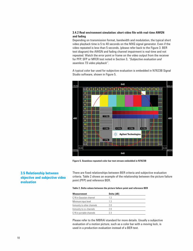
A typical color bar used for subjective evaluation is embedded in N7623B Signal
Studio software, shown in Figure 5.
Figure 5. Seamless repeated color bar test stream embedded in N7623B
There are fi xed relationships between BER criteria and subjective evaluation
criteria. Table 2 shows an example of the relationship between the picture failure
point (PFP) and reference BER.
Table 2. Delta values between the picture failure point and reference BER
Measurement Delta [dB]
C/N in Gaussian channel 1.3
Minimum input level 1.3
Immunity to other channels 2.0
Immunity to co-channels 2.0
C/N in portable channels 2.3
Please refer to the MBRAI standard for more details. Usually a subjective
evaluation of a motion picture, such as a color bar with a moving lock, is
used in a production evaluation instead of a BER test.
3.5 Relationship between objective and subjective video evaluation

11
Figure 6. Agilent DVB-T/H receiver test system
Figure 6 shows a typical video receiver test system. Detailed descriptions of the
test equipment follow.
N7623B Signal Studio for digital video (Figure 7) is a versatile software tool that
simplifi es the creation of arbitrary waveforms for most digital video standards.
This includes formats such as DVB-T/C/H/S/S2, ISDB-T/TSB/TB, ATSC, J.83
Annex A/B/C, DTMB and CMMB. The N7623B software enhances support for
MPEG transport streams that fi t into 64 MSamples [DF2] memory. Play back
fully channel-coded digital video waveforms using E4438C ESG, N5182A MXG,
N5162A MXG ATE and E8267D PSG vector signal generators, high-performance
platforms that support a wide range of applications including cellular and
wireless connectivity communications.
In each broadcast standard, modulation types (QAM, QPSK or VSB), OFDM
parameters (subcarrier numbers guard the period length or FFT size) and burst
frames in DVB-H, are parameters that need to be considered when creating RF
waveforms.
Figure 7. N7623B Signal Studio for digital video interface
4. General Test
Diagram Introduction
4.1 N7623B Signal Studio fordigital video software
N7623B
MXG ATE
ESG
PSG
LAN N5115BP
ow
er splitter
Receiver test
BER/ video subjective evaluation
Waveforms
RF
Analog I/Q
Digital I/Q
STB/TV
mobile
receivers
MXG

12
4.2.1 N5182A MXG and N5162A MXG ATE vector signal generators
Figure 8a. N5182A MXG vector signal generator
Figure 8b. N5162A MXG ATE vector signal generator
The N5182A MXG (Figure 8a) offers the industry-best adjacent-channel power
(ACPR), accurate frequency amplitude levels, switching speeds and operation
reliability making it ideal for the characterization and evaluation of single and
multiple carrier tuner, mixer and power amplifi ers in large scale manufacture.
The typical uncertainty of the N5182A is ±0.6 dB at +7 dBm to –60 dBm
when carrier frequency under 1 GHz. The typical single side band (SSB) phase
noise of N5182A is 500 MHz –126 dBc/Hz with 20 KHz offset at 500 MHz and
–121 dBc/Hz with 20 KHz offset at 1GHz. N5162A MXG ATE (Figure 8b) is
streamlined for automated test equipment (ATE) needs with removal of front
panel and and all connectors relocated to the rear panel for convenient and
secure rack confi gurations. The MXG ATE delivers fast switching speeds, high
power, and low distortion performance. For details please refer to the N5182A
MXG and N5162A MXG ATE Vector Signal Generators Data Sheet, 5989-5261EN.
4.2.2 E4438C ESG vector signal generator
Figure 9. E4438C ESG vector signal generator
The E4438C ESG (Figure 9) provides lower phase noise, industry-leading
modulation error ratio (MER) performance, excellent level accuracy, fading
capabilities, and digital I/Q inputs and outputs making it better suited for early
R&D receiver or component test. The digital I/Q input and output interface to
N5115B Baseband Studio for fading, makes it an ideal platform for conformance
test in R&D.
4.2 Signal generator platforms

13
4.2.3 E8267D PSG vector signal generator
Figure 10. E8267D PSD vector signal generator
The E8267D PSG (Figure 10) provides the highest performance for your
microwave test applications such as satellite communication application.
N5115B Baseband Studio for fading (Figure 11) is a powerful tool for verifying
your cellular communications, WLAN, or satellite communications receiver
designs. You can achieve realistic channel simulation using multipath fading
and AWGN, or simulate diverse or multiple antennas or interfering signals by
adding a second channel. Preconfi gured fading profi les simplify initial setup,
or you can create user-defi ned fading profi les to meet your specifi c test needs.
N5115B Baseband Studio for fading also provides support for digital input or
output using an N5102A digital signal interface module, enabling you to connect
directly to your device’s digital subsystem for added power and fl exibility.
Figure 11 N5115B Baseband Studio for fading
4.3 N5115B Baseband Studiofor fading and N5102Adigital interface

14
The test cases for the MBRAI standard can be divided into seven parts:
C/N performance, input signal levels, immunity to analog and/or digital signals
in other channels, immunity to co-channel interference, multipath reception
within the guard interval, multipath reception outside the guard interval and
impulsive noise.
This test determines the minimum and maximum input levels of the DUT, as
shown in Figure 12. For this purpose, MBRAI has or uses input level tests for
different channels. The amplitude accuracy of the DTV signal is important
because the trans region area between a good picture and “total blurred”
(“cliff” effect) is small leaving little room for error. The typical “cliff” region
for DVB-T is only 0.6 dB.
Figure 12. Example of a possible measurement setup for a minimum and maximum receiver
input test
Look at Figure 13 to see how reducing accuracy uncertainty reduces the
possibility of errors on receiver sensitivity measurements. For example, if
the wanted sensitivity level of the DVBT receiver is –90 dBm and the signal
generator has level uncertainty of ±2 dBm, the you may pick a receiver that only
has a –88 dBm sensitivity level because the test source has an output of +2.0 dB
uncertainty. Or you may throw away some receivers when the test signals are
–2.0 dB from the wanted reference of –90 dBm, even though the receiver really
has sensitivity of –90.0 dBm, not –92.0 dBm. The MXG has ±0.6 dB absolute
amplitude accuracy and 0.01 dBm resolution when the output frequency is
below 1 GHz.
Figure 13 Sensitivity measurements: range of errors (pick “wrong” and throw “right”)
5. MBRAI Receiver
Case Analysis
5.1 Receiver minimum andmaximum input signal levels(Chapter 6. or IEC 62002-2)
DVB-T/H Source +
seamless video/color bar +
real-time AWGNDUT
Sensitivity –90 dBmPick wrong
Pick wrong
Throw right
Throw right
–88.0 dBm
–90.4 dBm
–90.6 dBm
–92.0 dBm
+/– 2.0 dB
±0.6 dB

15
Channel simulation is an essential part of the design and verifi cation process:
this ensures the receiver is robust enough to provide reliable communication
under fading conditions. See Figure 14.
There are two methods of simulating the fading effect using the Agilent DTV
test system
■ ARB fading covers up to 20 paths, but doesn’t include mobile fading
(no Doppler fading)
■ N5115B Baseband Studio for fading covers all fading requirements in
MBRAI and provides Doppler fading (Jake’s method)
Baseband Studio for fading software provides the capability to change fading
parameters for large- and small-scale fading scenarios with wide signal
bandwidths. There is a real-time AWGN generator that can add real-time
noise on repeatable video signal based on ARB waveforms. The total effect
of the RF signal is a kind of real-time signal, called a pseudo real-time signal
for video performance test.
Figure 14. Example of a possible measurement setup for MBRAI tests: C/N performance
(Chapter 5), echo within (Chapter 9) and outside channel (Chapter 10) mobile SFN channel
(Chapter 13)
■ Carrier-to-noise (C/N) performance
(Chapter 5 of IEC 62002-2)
This test measures the carrier-to-noise ratio required to reach the appropriate
failure point criteria.
In order to determine the C/N performance of the DUT, different channel types
are used:
• Gaussian: ideal channel conditions
• Portable: multipath channel without a direct path
• Portable indoor (PI) and portable outdoor (PO)
• Mobile: terminal is moving in a car
■ Guard interval utilization: echoes within or outside the guard interval
(Chapter 9/10 of IEC 62002-2)
The performance of a receiver is determined while echoes within and outside
the guard interval occur. The receiver should be able to handle two static echo
paths in the channel when the echoes are within the guard interval. During
the test, various delayed echoes are applied to the useful signal for echoes
outside the guard interval.
■ Mobile single frequency noise channel test
(Chapter 13 of IEC 62002-2)
The SFN channel tests verify that the receiver synchronization works correctly
in the mobile SFN environment. The mobile performance should remain within
a specifi ed level. The requirements and this test apply to DVB-H receivers.
5.2 Channel simulation:fading and AWGN
DVB-T/H
source
Channel
simulator
Noise
sourceDUT
N5115B Baseband Studio for fading

16
There are four types of interference tests in digital TV receiver test:
Chapter 7 – immunity to analog and/or digital signals in adjacent channels
Chapter 8 – immunity to co-channel interference from analog TV signals
Chapter 11 – tolerance to impulse interference
Typically more than one signal generator is necessary for this measurement
set as shown in Figure 15.
■ Analog TV signal in adjacent channels1
■ Digital TV signal in adjacent channels
■ Analog TV signal in co-channel1
■ Impulsive interference signals1
Figure 15. Example of measurement setup for immunity to analog and digital signals (Chapter 7),
co-channel analog TV signals (Chapter 8) and impulsive interference (Chapter 11) tests
5.3 Interference and immunitytests (Chapter 7, 8 & 11 ofIEC 62002-2)
1 Agilent provides recorded analog PAL or SECAM TV waveforms as interference signals to
confi gure the S1, S2, L1, L2, L3 and L4 test patterns defi ned in Chapter 7 and Chapter 8 of
MBRAI. The same waveforms are used for impulse interference signal defi ned in Chapter 11
of MBRAI. Agilent provides some example waveforms for impulse interference testing in
MXG/ESG playable waveforms. These waveform can be recorded using the RF signal
recording tools of the N89601A software on PSA or MXA spectrum analyzer.
DVB-T/H
Source wanted signal
Adjacent digital TV
ESG/MXG
Analog TV
Impluse interference
Agilent waveforms
Third parties’ sources
Receiver
DUT
Pow
er
com
biner

17
■ Immunity to analog and/or digital signals in adjacent channels
(Chapter 7 of IEC 62002-2)
This scenario determines the performance of a receiver device in the presence
of analog and/or digital signals in adjacent channels. Different test scenarios are
specifi ed. The S1 and S2 patterns, contain only one analog or digital interferer.
The test patterns L1, L2, L3 and L4 show two interferer signals (analog; digital).
■ Immunity to co-channel interference from analog TV signals
(Chapter 8 of IEC 62002-2)
The co-channel interference test simulates an analog TV signal interfering with
the actual useful signal in the same channel. PAL I1, B/G and SECAM signals
(depending on the area of operation) are overlaid on the useful signal.
■ Tolerance to impulse interference
(Chapter 11 of IEC 62002-2)
This test determines the performance of receivers when impulsive noise
interference is present. The carrier-to-noise value for the impulsive interference
is decreased for various noise conditions in one channel.
N7624B Signal Studio can easily create a GSM900 TX signal on the MXG or
ESG which simulates the block condition in DVB-T/H receiver test defi ned in
Chapter 11 of MBRAI. With a second MXG or ESG signal generator for GSM900
signals the blocking test can be conducted as shown in the diagram of Figure 16.
Figure 16. Example of a measurement setup for a GSM900 TX signal blocking test; a continuous
wave (CW) source provides a GSM modulated interference signal
GSM900 TX signal blocking test (Chapter 12 of IEC 62002-2)
The blocking test should verify that the receiver sensitivity does not degrade
too heavily when a GSM900 TX blocking signal is present at the receiver input.
An alternative method is to use a FM modulated carrier to simulate the worst
interferences that come from GSM. This is shown in Figure 16.
5.4 GSM900 TX signal blocking test
DVB-T/H
source
CW
sourceHighpass
filter
Power
combinerDUT

18
Table 2. Supported frequency ranges and mobility
The receiver performance fi gures are all specifi ed at the reference point
(Figure 17), which is the input of the receiver. All conformance testing is
performed at the same point. In a case where the GSM rejection fi lter is
included (terminal category c), the measurements will be carried out at the
front of the GSM rejection fi lter.
In the case of a DVB-H receiver, manufacturers shall provide the specifi ed test
mode in which the following parameters can be monitored:
• TS-BER after Viterbi decoder
• TS-PER (picture error rate)
• MPE FER (FER) (frame error rate before MPE-FEC)
• MPE-FEC FER (MFER) (frame error rate after MPE-FEC)
Figure 17. DVB-T/H test reference model, from page 18 of MBRAI part I specs (V2.1.0)
6. Examples of Typical
DVB-T/H Receiver Tests
Terminal
categoryMobile VHF III UHF IV UHF V
aIntegrated car
terminalsYes
Yes, in areas
where
VHF is used
for DVB-T.
Yes Yes
b1Portable
digital TV-setsNo
Yes, in areas
where
VHF is used
for DVB-T.
Yes Yes
b2Pocketable
TV-setsYes Optional Yes Yes
cConvergence
terminalsYes No Yes
Yes / up to
55 channels
(746 MHz)
FieldstrengthΕ
AntennagainGa
Optional externalantenna connector
NoisefactorF
InputpowerРm
OptionalGSMreject filterLGSM
RF-Referencepoint
TS-Referencepoint
IP-Referencepoint
FER-Referencepoint
MFER-Referencepoint
Only in DVB-H receiver
IP-OutDVB-T
demodulator
DVB-Htime
slicing
DVB-HMPE-FEC
DVB-HIP-
De-encapsulation

19
In a case of QPSK modulated signals (DVB-T) with a code rate 1/2 in an 8 MHz
channel (Channel 45), the following requirements need to be met (Figure 18):
■ Minimum input level: –94.6 dBm
■ Maximum input level (terminal category b, c): –28 dBm or higher
■ Payload–>Data source type: Demo fi le; PAL or NTSC (depending on the
TS decoder output)
Figure 18. Easy confi guration of a sensitivity test signal using the N7623B
Generate and download the waveform to the MXG. It will take about 8 minutes
to complete the download because the waveform is so large. Fortunately the
waveform can be saved on MXG so you won't need to download it every time.
Tip: Ftp will be the fastest way to download the fi le; then you can download the
waveform directly using buttons on N7623B’s GUI.
Minimum input levels
Adjust the DVB-T/H signal source power level until the receiver reaches the
reference BER criterion 2 x 10⁻⁴ after the Viterbi decoder (failure criterion a).
Alternatively, the picture failure point (PFP) criterion (failure criterion b) may be
used. For DVB-H receivers a 5% MFER criterion is used. Measure the power level
at the terminal reference point. Once the reference failure criterion is reached,
the re-synchronization needs to be achieved.
Try to adjust the amplitude by 0.1 dBm when the signal approaches the minimum
level as the BER measurement result will change dramatically due to the “cliff
effect” at the receiver sensitivity point.
Maximum input level
Adjust the DVB-T/H signal source power level to the defi ned maximum value.
Measure the reference BER after the Viterbi decoder (failure criterion a).
Alternatively, the picture failure point (PFP) criterion (failure criterion b) may
be used. For DVB-H receivers a 5% MFER criterion is used. Once the reference
failure criterion is reached, the re-synchronization needs to be achieved.
PFP criterion of a receiver is used in this example.
6.1 Minimum and maximum receiver input signal levels

20
This test determines the point TP4 (characterization point for C/N versus
Doppler) in IEC 62002-1 for DVB-H receivers. See item 3 of Table 6.
N7623B Signal Studio for digital video:
Frequency: 666 MHz
Level: –50 dBm
FFT: 8k; constellation: 16QAM; guard interval: 1/4; code rate: 1/2;
MPE-FEC CR: 3/4; embedded in DVB-H TS stream defi ned by user
(Not a physical layer parameter)
N5115B Baseband Studio for Fading:
Doppler Shift: 10 Hz
Figure 19. Set 10 Hz Doppler shift in N5115B
Note: For C/N test in other fading environments (no mobile movement), the
N7623B provides faded ARB waveform creation capability, so a separate
baseband fader is not needed for most of fading test cases (Figure 20).
Figure 20. Static fading setting embedded in the N7623B
6.2 C/N performance

21
As part of this example, test pattern L1 includes an analog and a digital interferer
signal with the following characteristics (Figure 21):
Figure 21. Adjacent digital/analog TV channel interference, (from page 41 of MBRAI part I)
The interferers are set to the maximum allowable level.
For terminal categories a and b1:
Analog interferer –25 dB (mW), digital interferer –30 dB (mW)
For terminal categories b2 and c:
Analog interferer –35 dB (mW), digital interferer –40 dB (mW)
Step 1. The useful DVB-T signal in the example above for channel N=45
(666 MHz) has the following characteristics.
N7623B Signal Studio for digital video for the wanted signal:
• FFT: 8k
• Constellation: 16QAM
• Code rate = 2/3
• Guard interval = 1/8
N7623B Signal Studio for digital video for the wanted interference signals:
The DVB-T interferer signal needs to be compliant with ETSI EN 300 744. In this
example, it is same as the wanted signal with proper amplitude and frequency.
Step 2. The analog PAL B/G interferer needs to meet following requirements:
• Modulating signals: 75 % color bar, 1 kHz FM sound with ±50 Hz
deviation, any NICAM modulation
• Level ratio vision carrier/FM carrier: 13 dB
• Level ratio vision carrier/NICAM carrier: 20 dB
• Filter roll off factor: 40 %
Download the waveform name “L1 Pattern PAL B-G” (or use a third party analog
TV signal generator) and set the frequency (696 MHz), amplitude (–25 dBm) on
the second MXG, suppose the DUT is category a) or b1).
6.3 Immunity to analogand/or digital signals inadjacent channels
DVB-T/H
DVB-T/H
α dB
b dB
N N+1 N+2 N+3 N+4

22
Step 3. Generate the digital interference channel with same confi guration as
the wanted signal on the third MXG and set the amplitude to –30 dBm and the
frequency to 682 MHz.
Adjust the amplitude of wanted signal to calculate the PFP out on the receiver
screen at 666 MHz (Channel 45). The difference shall be higher than the
requirement in Table 3.
Table 3. Adjacent interference tolerances defi ned in MBRAI
Mode a[N+2] b[N+4]
2k/8k 16-QAM CR=1/2 GI=1/8 40 dB 45 dB
2k/8k 16-QAM CR=2/3 GI=1/8 40 dB 45 dB
2k/8k 16-QAM CR=3/4 GI=1/8 36 dB 41 dB
2k/8k 64-QAM CR=2/3 GI=1/8 32 dB 37 dB
The following parameters are used for the test.
N7623B Signal Studio for digital video (Figure 22):
• Channel 45 (666 MHz)
• Level: –40 dBm
• FFT: 8k; constellation: 64QAM; code rate = 2/3; guard interval = 1/8
Figure 22. DTV signal test setup in N7623B
6.4 Guard interval utilization:echoes within the guard interval

23
N7623B Signal Studio for digital video. (Figure 23):
• Real-time Noise: ON
• Carrier to Noise Ratio: 26.2 dB
• Carrier bandwidth: 8.0 MHz
• Noise Bandwidth Factor: 2
Figure. 23 Real-time AWGN setup in N7623B
N5115B Baseband studio for fading (Figure 24):
Echoes
• Path 1: Attenuation = 0 dB, delay = 0 s
• Path 2: Attenuation = 0 dB, delay = 100.8 Ys
• Path 3: Attenuation = –1 dB, delay = 100.8 Ys, Doppler shift = 0.2 Hz
Figure 24. Echo path setup in N5115B
The minimum echo requirements are presented in Table 4.
Table 4. Performance with echoes within the guard interval, from MBRAI
Mode C/N BER
8K, 16-QAM, CR=1/2, GI=1/8 16.3 dB < 2x10E–4
8K, 16-QAM, CR=2/3, GI=1/8 26.2 dB < 2x10E–4

24
In order to ensure that the receiver synchronization also works correctly in a
mobile SFN environment, three mobile SFN channel models (weak long echo,
strong long echo, strong short echo) are checked.
The useful DVB-H signal needs to show following characteristics:
N7623B Signal Studio for digital video:
• Channel 45: 666 MHz
• FFT: 8K; constellation: 16QAM; code rate = 1/2; guard interval =
1/4; MPE-FEC = 3/4;
The payload is a user-defi ned TS video fi le that is compliant to DVB-H standards
with time slice enabled.
N5115B Baseband Studio for fading (Figure 25)
For this example, the weak long echo channel is chosen. There are twelve
Rayleigh paths, defi ned as follows: (Delay/us, Power/dB): (0.0/–3), (0.2/0),
(0.5/–2), (1.6/–6), (2.3/–8), (5.0/–10), (179.2/–13.6), (179.4/–10.6), (179.9/–12.6),
(180.8/–16.6), (181.5/–18.6), (184.2/–20.6).
Figure 25. Mobile SFN fading (no Doppler shifting) in N5115B Baseband Studio for fading
6.5 Mobile SFN channel test

25
Guard interval = 1/4 8k Speed at Fd3dB km/h
Modulation Code rate MPE-FEC CR C/Nmin dB Fd3dB Hz 474 MHz 746 MHz
16-QAM 1/2 3/4 15.5 100 228 145
Additionally apply a Doppler shift of 10 Hz at the primary path (Figure 26). With
this setting, the C/N value can be varied until C/Nmin is met. With this value,
you can vary the Doppler shift setting to check for MBRAI compliance.
Figure 26. Mobile SFN fading setting (with a 10 Hz Doppler shift) in N5115B Baseband Studio for
fading
The fi rst Doppler frequency in the channel simulator is set to 10 Hz and the
C/N value is adjusted by changing the noise source signal level until the
receiver reaches 5% MFER criterion. The resulting C/N ratio is the C/Nmin.
Next the C/N ratio is increased by 3 dB from the specifi ed C/Nmin. The Doppler
frequency is then adjusted until the receiver reaches 5% MFER for the DVB-H
receiver. The resulting Doppler frequency is Fd3dB (Table 5).
Table 5. C/N (dB) for MFER 5% for DVB-H
26
The Microsoft® .NET-based application programming interface (API) is
provided to enable systematic and effi cient confi guration of complex digital video
waveforms. It allows programmatic setting of signal parameters by importing
custom data sets or using programming loops and mathematical functions rather
than manually entering data in the Signal Studio graphical user interface. The
entire signal confi guration and playback process can easily be automated in
your own programming environment using the API. Included with the software
is a full API. Use the API to set parameters either programmatically or by using
an API graphical user interface. The API's built-in Help System provides
programming examples that you can easily fellow.
7. Receiver Production
Recommendation
7.1 Application programming interface (API)

27
Clause Conditions Terminal category
acar terminals
Terminal category
b1portable TVs
Terminal category
b2pocketable TVs
Terminal category
chand-held
convergence terminals
5. C/N performance
Ch 45
Gaussian All modulations, 2k/4k/8k S M/E X X
Portable All modulations, 2k/4k/8k S M/E X
PI / PO 16-QAM 2/3, 3/4, 64-QAM 2/3, GI 1/4, 8k
QPSK 1/2, 2/3,16-QAM 1/2, 2/3,
MPE-FEC 3/4,GI 1/4, 8k
S X
Mobile
QPSK 1/2, 2/3, 16-QAM 1/2, 2/3,
64-QAM 2/3GI 1/4, 8k
QPSK 1/2, 2/316-QAM 1/2, 2/3,
MPE-FEC 3/4, GI 1/4, 8k
S E B X
6. Receiver minimum and maximum input
signal levels
Minimum and maximum input
levels
Ch 21, 45, 64 (UHF), Ch 8, 12 (VHF)
QPSK 1/2 S M/E X X
7. Immunity toanalog
and/or digitalsignals in
other channels
S1
N±1: Ch 45 (UHF), Ch 8 (VHF) with 64-QAM 2/3 additionally Ch 21, 64 (UHF),Ch 5, 12 (VHF). N±2: Ch 45 (UHF), Ch 8 (VHF)
S A 3M/E X X
16-QAM 3/4 , 16-QAM 2/3, 16-QAM 1/2 , 64-QAM 3/4 , 64-QAM 2/3, GI 1/8
S2Ch 45 (UHF), Ch 8 (VHF) S A 3M/E X
QPSK 1/2, 2/3, 16-QAM 1/2, 2/3, 3/4, 64-QAM 2/3, 3/4, GI 1/8
L1-L3
Ch 21, 45, 64 (UHF), Ch 8 (VHF) S A 3M/E X X
16-QAM 1/2, 2/3,3/4, 64-QAM 2/3,
GI 1/8, 8k
16-QAM 1/2, 2/3,3/4, 64-QAM 2/3,
GI 1/8, 8k
16-QAM 1/2, 2/3,3/4, 64-QAM 2/3,
GI 1/8, 8k
QPSK 1/2, 2/3,16-QAM 1/2, 2/3,
GI 1/8, 8k
L4 Ch 43 S 3M/E X
QPSK 1/2, 2/3,16-QAM 1/2, 2/3,
GI 1/8, 8k
QPSK 1/2, 2/3,16-QAM 1/2, 2/3,
GI 1/8, 8k
QPSK 1/2, 2/3,16-QAM 1/2, 2/3,
GI 1/8, 8k
QPSK 1/2, 2/3,16-QAM 1/2, 2/3,
GI 1/8, 8k
8. Immunity toco-channelinterferencefrom analogTV signals
Ch 45 (UHF) S A 2M/E X
16-QAM 1/2, 2/3,3/4, 64-QAM 2/3,
3/4, GI 1/8
QPSK 1/2, 2/3,16-QAM 1/2, 2/3,
MPE-FEC 3/4,GI 1/4, 8k
9/10. Guardinterval utilization:
echoes within/outsideguard interval
Ch 45 (UHF) S E B X
8k, 64-QAM 2/3, GI 1/88k, 16-QAM 1/2, GI 1/8
11. Toleranceto impulse
interference
Ch 45 (UHF) S A 2M/E X
8k, 64-QAM 2/3, GI 1/88k, 16-QAM 1/2, GI 1/88k, 16-QAM 2/3, GI 1/8
12. GSM900 TXsignal blocking
test
8k, GI 1/4, QPSK1/2CR MPE-FEC
3/4, C55S 2M/E X X
13. Mobile SFNchannel test
8k, GI 1/4, 16-QAM 1/2 MPE-FEC
3/4, C45S M/E B X
Larg
e Volu
me M
anu
factu
re
Pre P
roduction
Baseban
d Stu
dio for fading =
B
Sig
nal g
enera
tors M =
MX
G /
E = ES
G
N7623B
= S
PA
L/S
ECA
M/
Pulse =
ATable 6. Summary of receiver test items from MBRAI
7.2 Recommended MBRAI test items

28
■ DVB-T standard: ETSI 300 744: Digital Video Broadcasting (DVB):
Framing structure channel coding and modulation for digital terrestrial
television
■ DVB-H standard: ETSI 302 304: Digital Video Broadcasting (DVB):
Transmission System for Handheld Terminals (DVB-H)
■ EICTA MBRAI 2.0 MOBILE AND PORTABLE DVB-T/H RADIO ACCESS:
(Part 1: Interface specifi cation)
■ EICTA MBRAI 2.0 MOBILE AND PORTABLE DVB-T/H RADIO ACCESS:
(Part 2: Interface conformance testing)
■ ETSI EN 300 744 Final draft, “Digital Video Broadcasting (DVB);
Framing structure, channel coding and modulation for digital terrestrial
television”, V1.5.1, June, 2004
■ ETSI EN 300 429, “Digital Video Broadcasting (DVB); Framing structure,
channel coding and modulation for cable systems”, V1.2.1, April, 1998.
■ ETR 290, “Digital Video Broadcasting (DVB); Measurement guidelines
for DVB systems”, May 1997
■ DTG RF Sub-Group document No.67, part 11, “UHF Transmission and
Reception”
Reference

www.agilent.com/fi nd/emailupdates
Get the latest information on the
products and applications you select.
www.agilent.com/fi nd/agilentdirect
Quickly choose and use your test equip-
ment solutions with confi dence.
Agilent Email Updates
Agilent Direct
www.agilent.com
For more information on Agilent Technologies’
products, applications or services, please
contact your local Agilent offi ce. The
complete list is available at:
www.agilent.com/fi nd/contactus
Americas
Canada (877) 894-4414
Latin America 305 269 7500
United States (800) 829-4444
Asia Pacifi c
Australia 1 800 629 485
China 800 810 0189
Hong Kong 800 938 693
India 1 800 112 929
Japan 0120 (421) 345
Korea 080 769 0800
Malaysia 1 800 888 848
Singapore 1 800 375 8100
Taiwan 0800 047 866
Thailand 1 800 226 008
Europe & Middle East
Austria 0820 87 44 11
Belgium 32 (0) 2 404 93 40
Denmark 45 70 13 15 15
Finland 358 (0) 10 855 2100
France 0825 010 700*
*0.125 €/minute
Germany 01805 24 6333**
**0.14 €/minute
Ireland 1890 924 204
Israel 972-3-9288-504/544
Italy 39 02 92 60 8484
Netherlands 31 (0) 20 547 2111
Spain 34 (91) 631 3300
Sweden 0200-88 22 55
Switzerland 0800 80 53 53
United Kingdom 44 (0) 118 9276201
Other European Countries:
www.agilent.com/fi nd/contactus
Revised: March 27, 2008
Product specifi cations and descriptions
in this document subject to change
without notice.
© Agilent Technologies, Inc. 2008
Printed in USA, May 30, 2008
5989-8446EN
Remove all doubt
Our repair and calibration services
will get your equipment back to you,
performing like new, when prom-
ised. You will get full value out of
your Agilent equipment through-
out its lifetime. Your equipment
will be serviced by Agilent-trained
technicians using the latest factory
calibration procedures, automated
repair diagnostics and genuine parts.
You will always have the utmost
confi dence in your measurements.
Agilent offers a wide range of ad-
ditional expert test and measure-
ment services for your equipment,
including initial start-up assistance,
onsite education and training, as
well as design, system integration,
and project management.
For more information on repair and
calibration services, go to:
www.agilent.com/fi nd/open
Agilent Open simplifi es the process
of connecting and programming
test systems to help engineers
design, validate and manufacture elec-
tronic products. Agilent offers
open connectivity for a broad range
of system-ready instruments, open
industry software, PC-standard I/O
and global support, which are
combined to more easily integrate
test system development.
AgilentOpen
www.agilent.com/fi nd/removealldoubt
Microsoft is a U.S. registered trademark of Microsoft
Corporation.